Solectek 36WAN1 SkyWay MAX User Manual Part 2
Solectek Corporation SkyWay MAX Users Manual Part 2
Solectek >
Contents
Users Manual Part 2
Operator’s Guide10
SkyWay-MAX
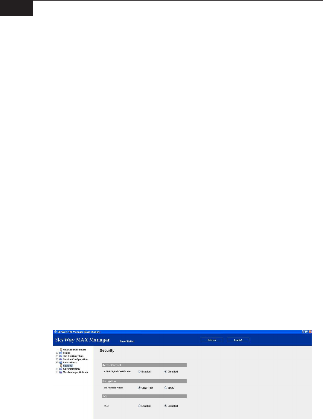
B. Security
This section details the security elements of the SkyWay MAX system as they relate to Network Entry.
BSID Match
The BSID is a unique, 6 octet (12 hex digit) identier assigned to each BSU at the factory. The rst 3 octets
are assigned a xed value of 00000B, a Solectek identication. The nal 3 octets are factory assigned the
same value as the nal 3 octets of the BSU’s RF MAC address. These nal 3 octets can be changed by the
Operator, if desired.
During an RF channel scan, the SS is searching for a BS wireless network to join. The BSID Match feature
ensures than an SS only joins a BSU listed in its BSID table. To make initial provisioning simpler, the BSID
match feature is disabled by default. However, enabling this feature on the SS limits the risk of entry into an
incorrect network. The BSID list is hosted on each SS, and can contain one or more BSIDs.
=> Remember, the BSID Match enable/disable is an SS conguration parameter
Access Control List (ACL)
A MAC based, Access Control List feature is available on the BSU. When enabled, the BSU must be
provisioned with the RF MAC address of each SS which is granted network entry. Once the SS MAC address
is added to the BSU, this SS will be tracked by the management system. If an SS attempts to join this BSU
network without an corresponding ACL entry, it will be rejected.
The ACL feature is disabled, by default. In this state, an SS which tries to join the network without a
matching ACL MAC address, will be granted entry, but considered an unknown SS. Once services are
dened for this SS, the unit will then be considered provisioned.
X.509 Digital Certicates
The X.509/PKM protocol set is an industry standard authentication method used to verify the credentials of
an SS. When enabled, the SS credentials are validated by the BSU in a secure fashion. Rogue SS units, those
not containing signed and validated X.509 digital certicates, are rejected from the BSU network.
This feature is managed by the BSU, and is disabled, by default.
Data Encryption
Further security of network trac is provided by the data encryption system. When enabled, all sector-
wide data is encrypted with the selected algorithm (Triple DES or AES) based upon a set of rotating
encryption keys.
This feature is managed by the BSU, and is disabled, by default.

SkyWay-MAX
Operator’s Guide11
C. Open Mode vs Pre-provisioning
When a system is congured in Open Mode (as shipped from the factory), SS units will join BSU networks as
unknown subscribers. Both Administrative and User Services can be added to desired unknown subscribers,
making the SS fully provisioned.
When an SS is pre-provisioned in the BSU, all Network Entry and Services information about the SS is set
up before the SS attempts to connect to the BSU. Once aligned, the SS enters the network and all pre-
provisioned services are added to the system. Based upon these services, network trac will begin owing.
D. Network Entry Completion
Once network entry is completed successfully, the SS is considered to be connected to the BS and service
provisioning can then begin. An SS that does not complete network entry successfully will continue to scan
the channels indenitely in an attempt to nd a BSU sector that will allow it to enter.

Operator’s Guide12
SkyWay-MAX
III. Services
A. Primer
To maximize utilization of scarce RF spectrum and to ensure the highest level of control over network
trac, WiMAX/802.16 technology has been design to pass network trac through logical connections
between a BSU and one or more SS’s. These connections are called wireless service ows, or services, and
allow an operator to lter, groom and prioritize network trac in a highly granular fashion.
The critical operation of services can be broken into a two stage process.
The rst stage is classication. This ltering process only allows packets onto a service when a pre-dened
set of packet characteristics are met. SkyWay MAX classication methods include combinations of 802.3,
VLAN and IP parameters. See Appendix C for a complete list of allowable service classiers.
The second stage involves the scheduling and transport of the packet across the wireless link, a process that
takes into account the QoS requirements of each active service as well as the current RF conditions. Each
service is assigned one of four possible scheduling types:
Unsolicited Grant Service (UGS) y
real-time Polling Service (rtPS) y
non real-time Polling Service (nrtPS) y
Best Eort (BE) y
Each scheduling type is associated with a set of target and guaranteed QoS parameters. This QoS
parameter set is dened by the service provider, and should be carefully tuned to the network service
being delivered. For example, IPTV, VoIP and basic internet browsing would each require unique Scheduling
Types and associated QoS Parameters.
Appendix C details the set of QoS parameters available for each Scheduling Type.
B. Administrative and User Services
As described above, services are required to carry network trac across the wireless system. To make
deployment more intuitive, the SkyWay MAX system references two types of services, Administrative and
User.
All networks require a number of administrative protocols running to provide basic functions such as
Authorization (PPPoE), IP Address assignment (DHCP), IP address resolution (ARP), etc. Since all wireless
trac must be carried on an active service, each SS must be provisioned with a set of appropriate services
to carry this trac.
To accelerate the deployment of SS units, SkyWay MAX Manager and EMS software provides a simplied
method of adding these Administrative Services. Both management tools provide the operator with a list
of available administrative protocols during the SS provisioning process. Once the protocols are selected,
the management system creates all of the necessary, underlying services required for support.
In contrast to Administrative Services, User Services transport true customer network trac. These services
are dened by the Operator with consideration for the type of network trac being carried (data, voice,

SkyWay-MAX
Operator’s Guide13
video), customer Service Level Agreements (SLAs) and the specics of the wireless deployment (range,
density, frequency re-use).
User services are provisioned per subscriber, per trac type and per direction (uplink, downlink). Each
service is assigned an ID, called the SFID.
C. Unicast and Multicast Services
Services can operate in either a unicast or multicast fashion. A unicast service denes a logical connection
between the BSU and a single SS. A multicast service denes a connection between the BSU and a dened
set of SS units. Multicast services are available in the downlink direction, only.
D. Service Classes
It is often the case that an Operator provisions many subscribers with the same set of QoS/SLA parameters.
To simplify the provisioning process, a Service Class can be dened to capture a set of QoS parameters that
will be used across the sector.
For example, for an Operator to deliver voice services, a set of QoS parameters should be dened
within the rtPS scheduling type. These parameters would include the appropriate packet min and max
throughput requirements, latency and priority. A VoIP Service Class can be created and named (e.g. - “VoIP
Gold”) to capture all of these parameter values. Once created, the VoIP Gold service class can be used to
provision services to any number of new or current Subscribers.

Operator’s Guide14
SkyWay-MAX
IV. Management Systems
The SkyWay MAX system provides a number of dierent management methods, suited for dierent
network deployment and management scenarios. With the exception of the SS pre-provisioning process,
most normal management functions are processed directly through the BSU.
A. Manager Application
The SkyWay MAX Manager Application is the most straightforward management system for Solectek’s
WiMAX equipment. This Manager system is built on a Java platform and is installed and can be operated
on a Windows XP PC.
Once installed and operational, the Manager can be pointed to any Solectek SkyWay MAX device, including
BSUs, SS and Indoor Controllers. The software provides full command and control of a device across pre-
provisioning, turn-up and operation/maintenance processes.
Since the Manager host PC logs directly into the device being managed, this management tool is best
suited for Host PC’s with local access within an Operator’s private network, and for managing small to
medium networks.
Please refer to Solectek document DOCS-1026, SkyWay MAX Manager Installation Guide, for more
information on the features and operation of this tool.
B. EMS System
For medium to large scale networks, Solectek’s EMS software is an ideal management solution. Hosted
on a dedicated NOC server residing within an Operator’s private network, the system provides multi-site
network wide status and control. Please contact Solectek Sales or Technical Support for more information
regarding the EMS system.
C. SNMP
Solectek’s BSU provides SNMP v1, v2 functionality through the use of both multiple MIBs: MIB II, 802.16f
WIMAX MIB, and Solectek’s private MIB.
SNMP functions can be mapped to an Operators existing SNMP Management system or related NMS/EMS
application.
Please contact Solectek Technical Support for more information and to obtain the latest supported MIBs.
D. Telnet
Each network element (BSU, SS) can be accessed and managed through a command line interface (CLI)
launched via a Telnet connection. See Appendix B for a full command list.
E. Serial Console
Accessed via a hard connection to Serial port, an RS232 Serial Console is available for the BSU only. It is
recommended that this management connection be used only for benchtesting and on-site debug work.
The commands available through the Serial Console are the same as those available from Telnet. See
Appendix B for a full command list.

SkyWay-MAX
Operator’s Guide15
V. Advanced Operation
A. Advanced RF
RSSI / CINR.
The instantaneous RF received signal strength (RSSI) and Carrier-to-Interference & Noise Ratio (CINR)
metrics are available in both the uplink and downlink direction. Both are important as indicators of the RF
link quality. RSSI is an absolute measure, calibrated in dBm. CINR is a ratio, or relative measure, calibrated in
dB.
Optimal RSSI
During the network entry process, in a stage known as ranging, the SS must adjust its power so that the
signal power received (RSSI) at the BSU equals the Optimal RSSI, a threshold stored in the BSU.
If the SS can not reach the Optimal RSSI value, it may still be allowed on to the network, but can likely only
support lower order modulations, that is, lower data rates.
Modulation
RF modulation, which determines the achievable data rate, is specied on a per-SS and per-direction
basis. Each SS has both an uplink and downlink modulation setting. The available modulations, and their
corresponding forward error correction (FEC) coding rates are as follows:
Modulation Coding Rate
AUTO n/a
BPSK 1/2Increased link reliability
QPSK 1/2
QPSK 3/4
QAM16 1/2
QAM16 3/4
QAM64 2/3
QAM64 3/4Increased data rate
The Auto Modulation feature provides a self-adjusting modulation dependant on the current RF link
conditions, as measured by the CINR. This process occurs independently per SS, and per direction.
Auto and Fixed modulation settings can be mixed within an RF network, or even an individual SS.
Multicast Modulation
Each downlink Multicast Service must also be assigned one of the modulation settings shown above. Once
selected, the modulation setting applies to all SS units with membership in a particular Multicast Service.
Thus the modulation should be chosen conservatively enough so that all member SS units can remain
connected to the service.

Operator’s Guide16
SkyWay-MAX
As an example, consider a situation where all SS units within a Multicast Service have sucient link margin
to support QAM64-2/3, except one SS which can only support QPSK-3/4. In order to retain service to all SS
units, the modulation should be chosen as QPSK-3/4, even though doing so sacrices system eciency.
When a Multicast Service modulation is set to Auto, the modulation self-adjusts to the highest data rate
that still supports all member SS units. The modulation selection is based upon the CINR values of all
member SS units.
B. Multi Sector Operation
The need to sectorize a base site occurs as network subscription outstrips the capacity of a single BSU
(sector). In this case, additional BSU sectors can be added to a base site. For Solectek’s SkyWay MAX
system, this also requires the provisioning of an Indoor Controller.
The Indoor Controller is a congurable and scalable system providing a number of functions to a multi-
sector base site:
Power + Data transport y
GPS Synchronization y
Remote Management (optional) y
BSU Failover Switching (optional) y
More information on the commissioning and operation of the Indoor Controller can be found in Solectek
document DOCS-1025.
SkyWay-MAX
Operator’s Guide17
VI. Administration
A. Notifications
BSU Notications use SNMP traps to actively alert an Operator’s management system (Manager Application,
EMS or SNMP Manager) of important changes in system status, including:
BSU reboot/restart y
SS exit or entrance to network y
Service add / delete / modication y
On the Manager Application, Notications can be viewed under Status : Notications, or by using the
quick-link from the Dashboard.
Once viewed, Notications can be erased or retained for future reference.
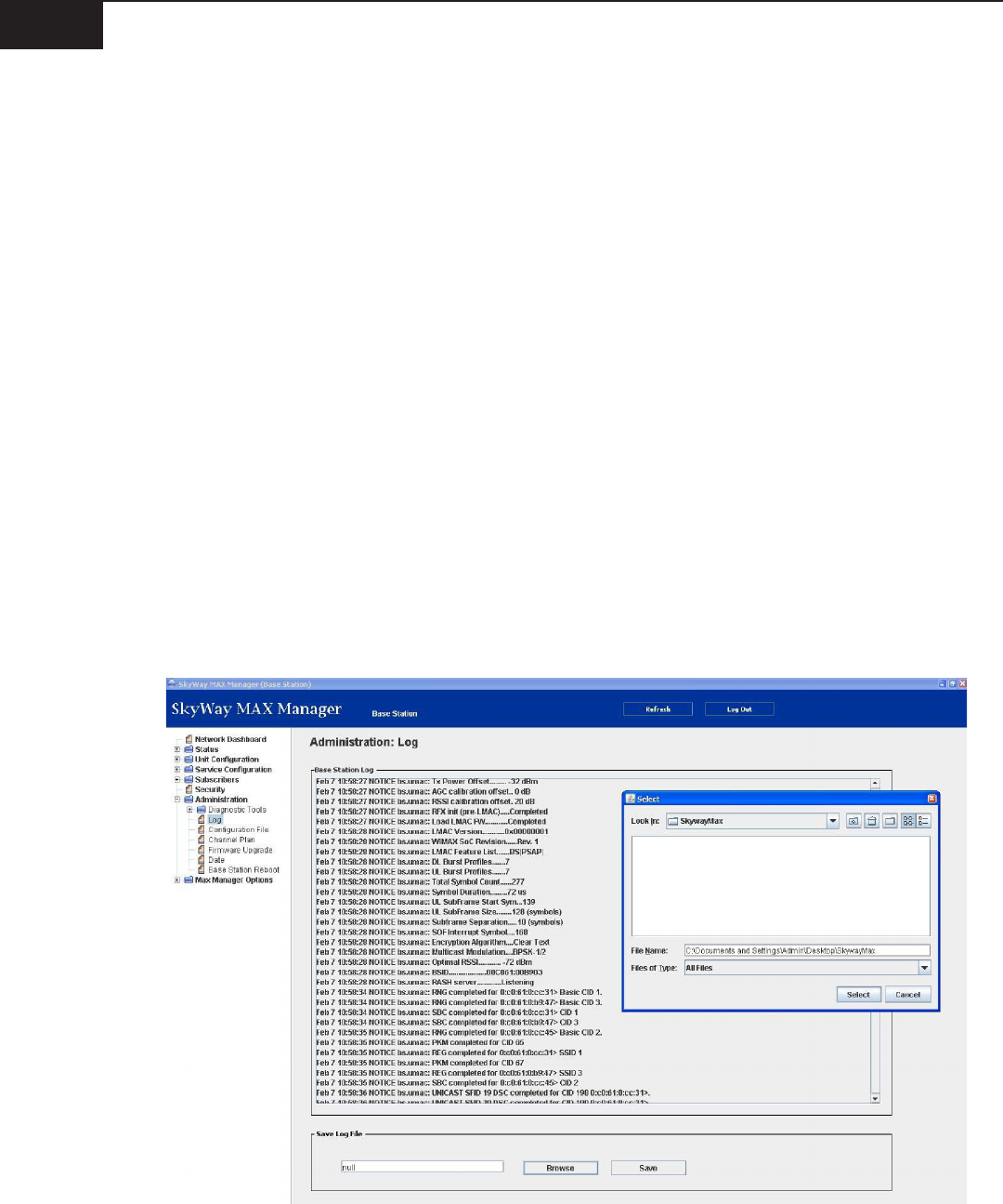
B. Event Logs
The SkyWay MAX BSU and SS devices automatically create and store a local event log le. This log is used to
capture and timestamp detailed information regarding all system conguration and status events.
A device log le can be viewed using either the Manager Application or EMS System, and/or exported
to a local PC for further analysis via FTP. This export process is depicted in the following screen from the
Manager Application:
Operator’s Guide18
SkyWay-MAX
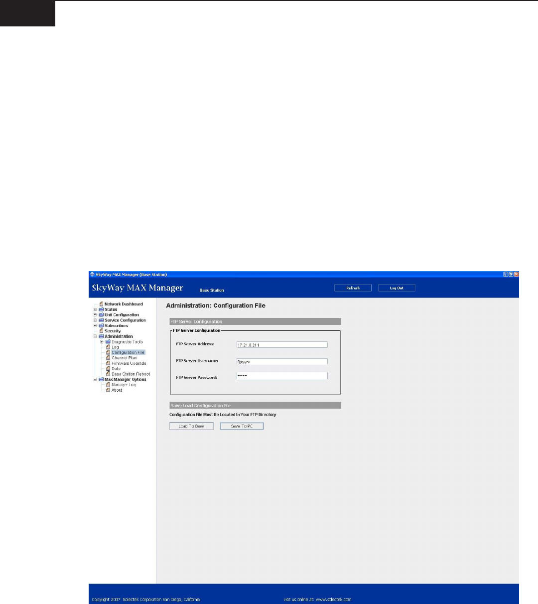
C. Configuration Files
In addition to using one of the many management systems available (e.g. - Manager Application, EMS,
SNMP, Telnet), the device conguration can be managed through the import and export of an XML
formatted conguration le.
Storing an operational BSU conguration o-line has several benets:
Reduces provisioning time of a new BSU in the event of a system failure y
Provides a ‘known-good’ starting point when debugging system problems y
Becomes a template for adding new BSU sectors y
For the SS, an o-line conguration le can act as a ‘golden le’ used to pre-congure each SS unit prior to
deployment.
The import and export of a conguration le is accomplished using FTP. The applicable Manager
Application screen is shown here:
SkyWay-MAX
Operator’s Guide19
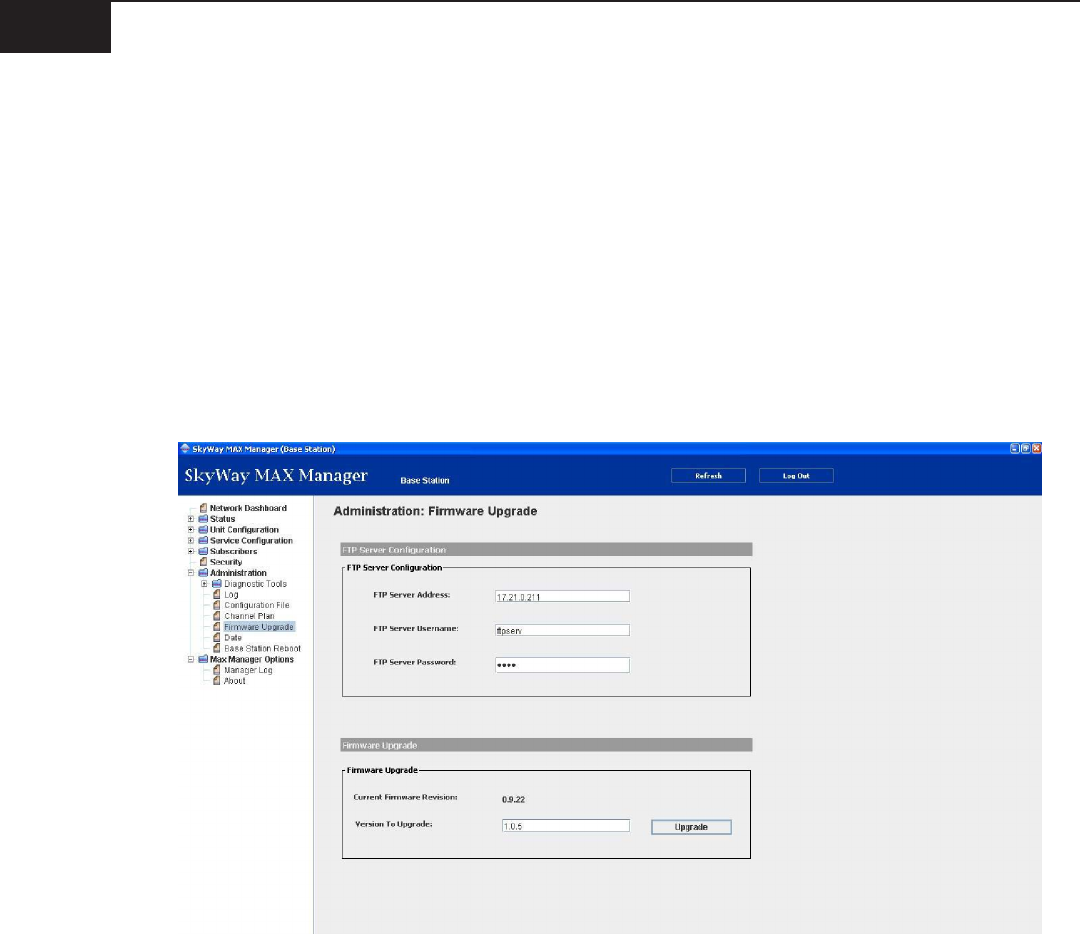
D. Firmware upgrade
The process of upgrading the device rmware is dependent on the management system being utilized.
When using the Manager Application, the following steps are followed:
Copy FW upgrade les to FTP target directory on Local PC y
Launch Manager Application on Local PC y
Point Manager Application to device requiring FW upgrade y
Navigate to yAdministration: FW Upgrade
Congure FTP server properties and FW upgrade version y
Press ‘Upgrade’ button y
E. Date/Time
In each wireless sector, the BSU is responsible for storing the local time and date. Once congured, this
information is stored in a battery-backed BSU real-time hardware clock.
During network entry, this date/time is passed to the SS.
The BSU has the option to obtain the current date and time from a variety of sources:
GPS, if available y
NTP Server, if available y
Operator Congured y
In all cases, the local time zone must also be congured in the BSU to allow accurate conversions from UTC
time.
Operator’s Guide20
SkyWay-MAX
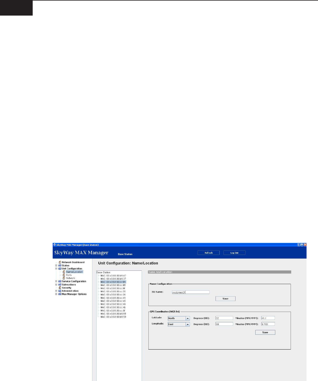
F. Name/Location
To improve usability, an Operator can choose to assign names and locations to the BSU and SS units. This
information can be assigned during initial provisioning, or anytime thereafter. Information for both the BSU
and SS is stored on the BSU.
Location information is stored as GPS coordinates in the following format:
Datum: WGS 84 y
Lat/Long HDDD MM.MMM, where: y
H=Hemisphere (N or S for Lat, E or W for Long)
DDD=Degrees, including leading zeros as necessary
MM.MMM = Minutes in decimal format
In addition, information on the BSU antenna beamwidth and bearing can be captured.
In total, the following elds are available:
BS y
Name
Location
Antenna Bearing
Antenna Beamwidth
SS y
Name
Location
Access to this information set on the Manager Application is via Unit Conguration: Name/Location