Solectek 36WAN1 SkyWay MAX User Manual Part 2
Solectek Corporation SkyWay MAX Users Manual Part 2
UserManual.wiki
>
Solectek
>
36WAN1 User Manual
>
Users Manual Part 2
Contents
1.
Base Installatuion Guide
2.
Users Manual Part 1
3.
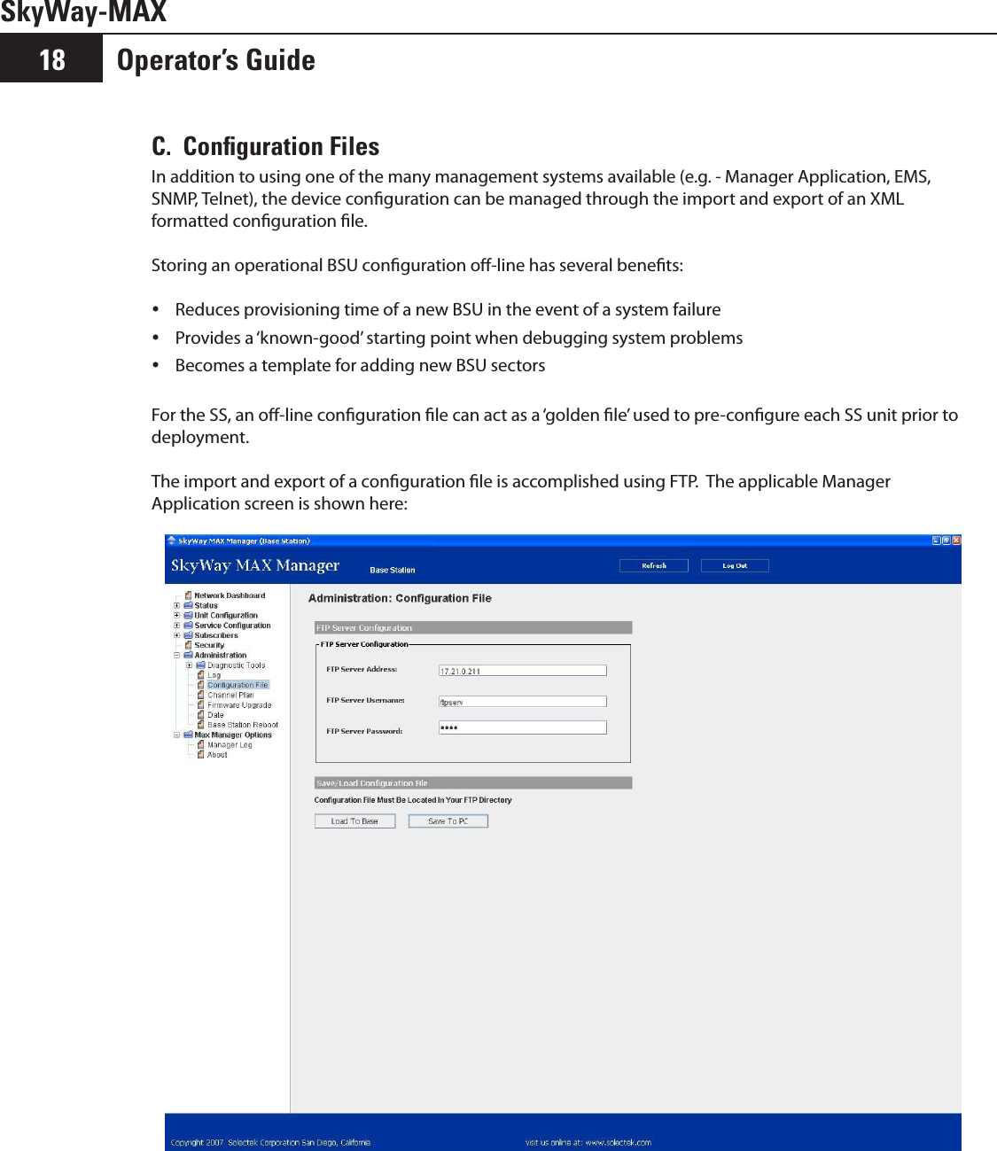
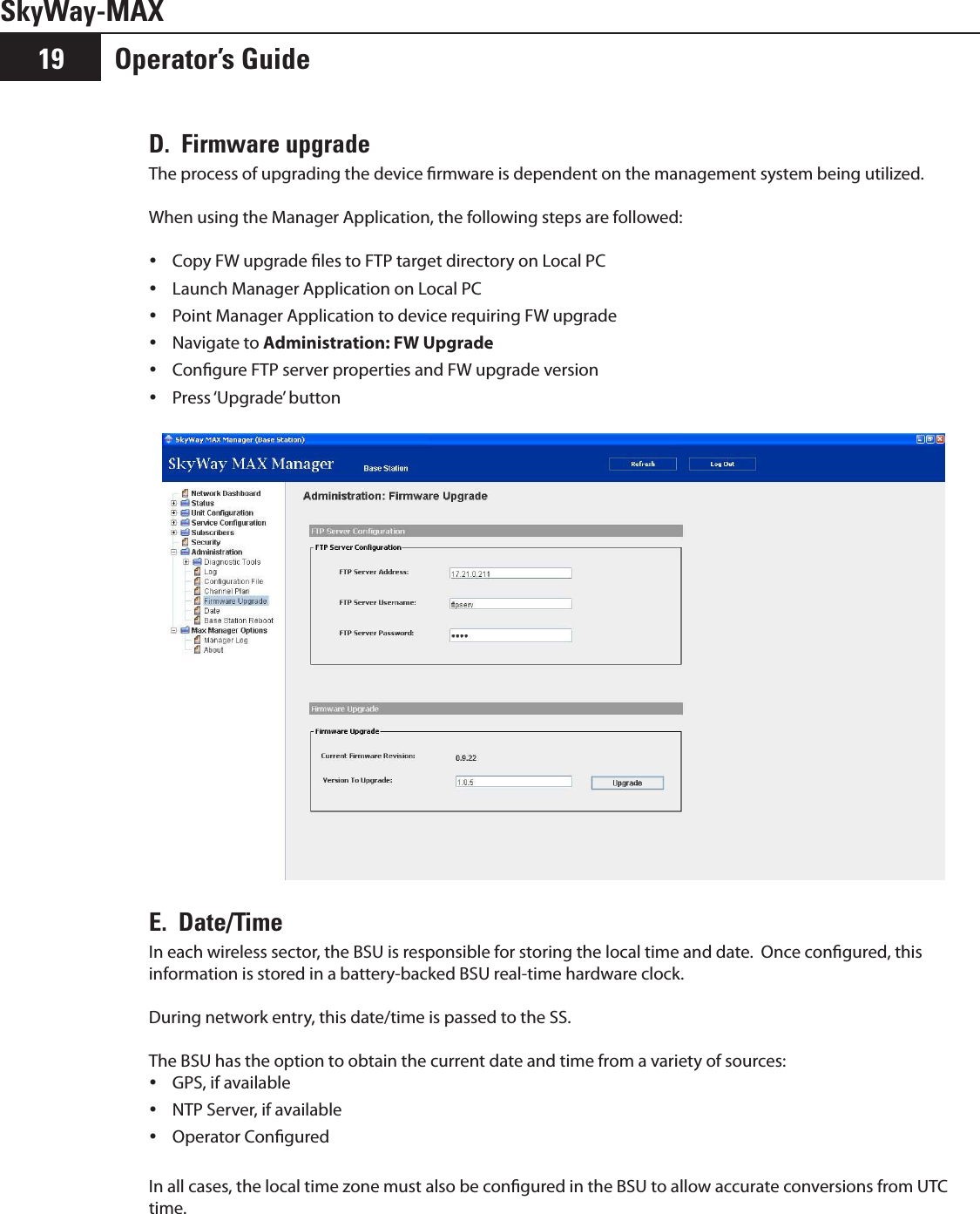
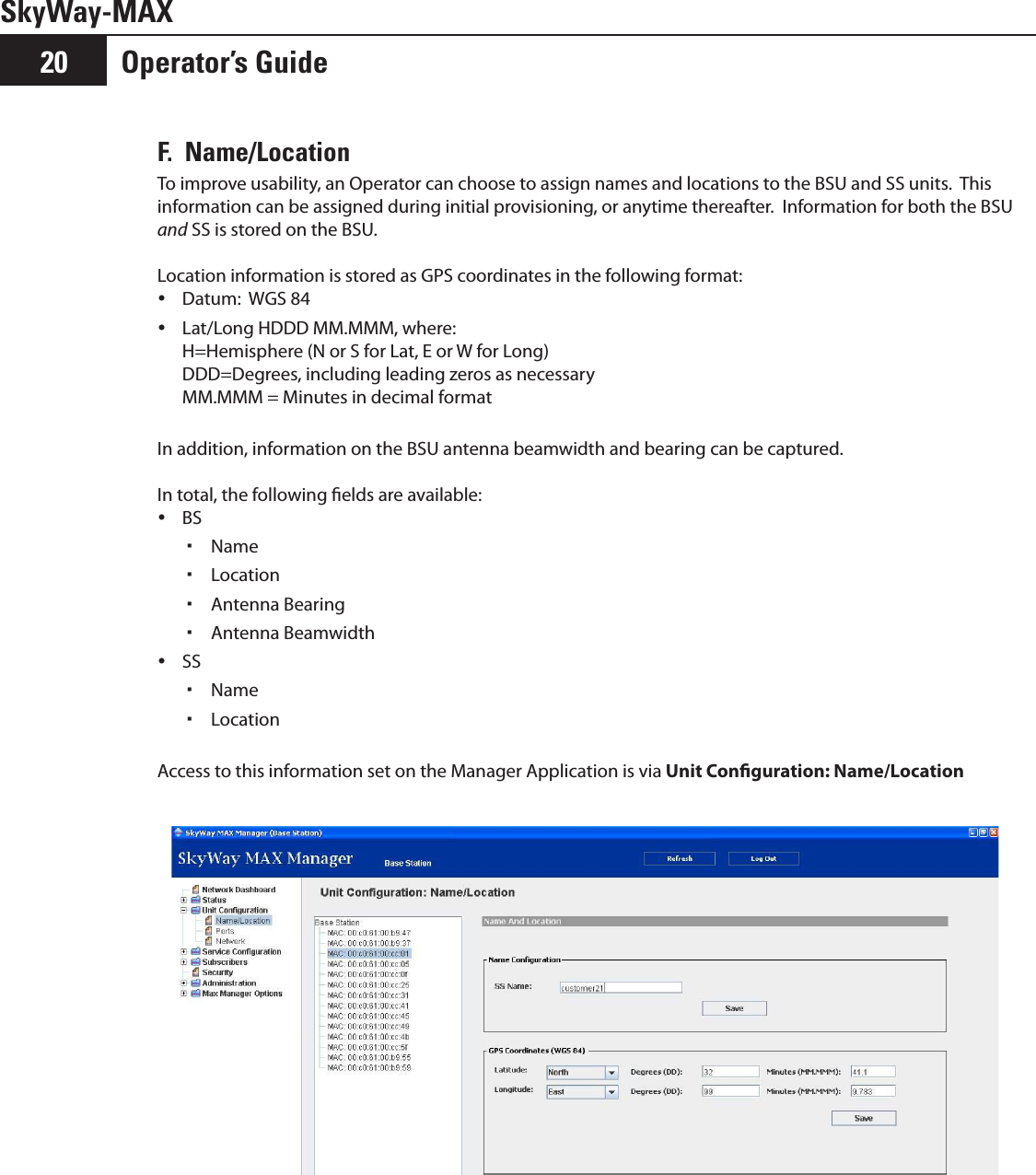
Users Manual Part 2
4.
Users Manual Part 3
5.
Additional User Manual Statement
Users Manual Part 2
Navigation menu
Upload a User Manual
Namespaces
Wiki Guide
HTML
PDF
Info
Views
User Manual
Discussion / Help
Navigation