Universal Avionics Systems 10801 Avionics Communication Management Unit User Manual 1
Universal Avionics Systems Corporation Avionics Communication Management Unit Users Manual 1
Contents
- 1. Users Manual 1
- 2. Users Manual 3
- 3. Users Manual 4
- 4. Users Manual 5
- 5. Users Manual 6
Users Manual 1
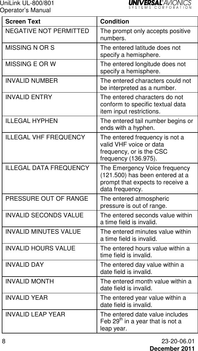
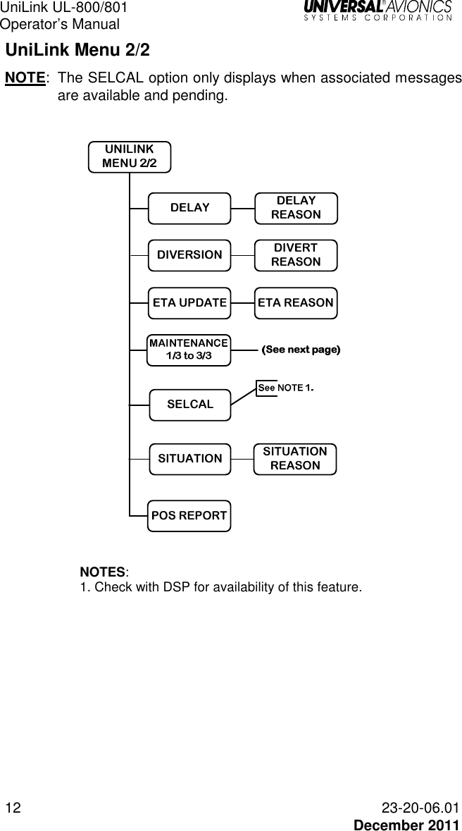
![UniLink UL-800/801 Operator’s Manual 2 23-20-06.01 December 2011 Operations Crew interface is accomplished through the FMS CDU and/or MCDU, utilizing a UASC FMS with SCN 1000.5/1100.5 or later. Data may be entered at any field highlighted by a cursor. The cursor is displayed in the first empty data field. Fields with plus signs (+) indicate information is required. Fields exhibiting minus signs (-) indicate input is optional. If there is no cursor displayed in a data field, selecting the ENTER key will place the cursor over the first enterable field on the page. Data is then entered into the field using the CDU/MCDU alphanumeric keys. In some situations, flight progress and related data from the FMS will be prefilled. Subsequent presses of the [ENTER] key will move the cursor to the next enterable field. Pressing a line select key (LSK) highlights the corresponding data entry field. Selecting [ENTER] when the cursor is in the last data field on the page results in the cursor parking off of the page. Pressing [ENTER] again positions the cursor on the initial enterable field on the page. FMS Input The FMS continuously provides current data to UniLink. Many messages and requests have fields that prefill with FMS flight progress data and computed information. In most cases the user accepts the data for inclusion into the message. It is possible however to change a value by overriding that value with a manual data entry. Manual entries are generally retained until power shutdown, although data that would normally change as a flight progresses will be cleared once the page has been exited (is no longer displayed). Source FMS The crew must ensure that the FMS that is navigating the aircraft (Source FMS) is the same FMS that supplies data to UniLink. The Source FMS is shown on the SOURCE FMS page, accessed via MAINTENANCE (1/3) > SENSOR STATUS > SOURCE FMS. SOURCE FMSselectionmethod selected fmsÎmanual {*}FMS1® FMS2® ¡¢z¬UNILINK RETURN®](https://usermanual.wiki/Universal-Avionics-Systems/10801.Users-Manual-1/User-Guide-1641686-Page-12.png)
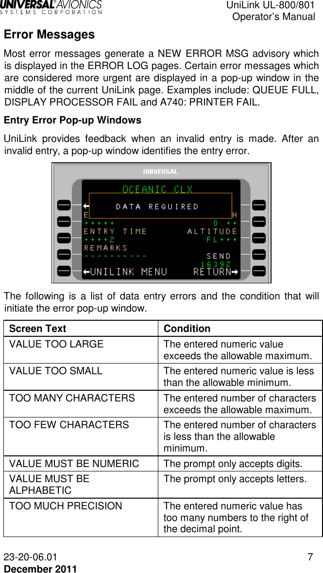
![UniLink UL-800/801 Operator’s Manual 23-20-06.01 3 December 2011 The Source FMS is indicated by an asterisk next to it. Any available FMS can be manually selected by pressing the adjacent LSK. If automatic (AUTO) selection is desired, the SELECTION METHOD LSK will toggle between MANUAL and AUTO. NOTE: It is important for the crew to ensure that the Source FMS is not changed prior to an expected flight plan modification uplink. If the Source FMS is changed prior to the uplink, the flight plan information will need to be transferred to the new Source FMS from the previously designated FMS. Communications Prior to entering Oceanic Airspace (and loss of VHF communications) the crew should suspend VHF and transition to satellite communication (See STATE under VHF DATA in the COMM CONTROL section). The crew must enable VHF communications once again when reentering a VHF-available region. Current Time On every UniLink screen above the RETURN option at LSK [5R], the current UTC time is displayed. SEND When the SEND LSK is pressed, the request is placed into queue for transmission. The delivery status of the message appears above the SEND option. If data required for the message has not been entered completely, the SEND option will display as inactive and if selected, a pop-up window DATA REQUIRED will display (indicating the data is insufficient).The SEND prompt will not display an arrow (indicating active) until all required data is entered. Clear the pop-up window by pressing any key or LSK.](https://usermanual.wiki/Universal-Avionics-Systems/10801.Users-Manual-1/User-Guide-1641686-Page-13.png)
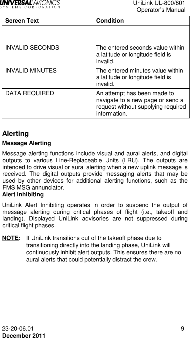
![UniLink UL-800/801 Operator’s Manual 23-20-06.01 5 December 2011 UniLink Advisories The bottom left LSK on each UniLink page will display either the UNILINK MENU prompt or UniLink advisories. UniLink advisories notify the crew of UniLink activity that may require user action. Only one advisory will display at a time in the order of priority. Pressing the adjacent LSK allows viewing of the advisory message. When no advisory is displayed, the advisory field is used to display the UNILINK MENU prompt. Selecting this prompt displays the UNILINK MENU. When on an FMS page, UniLink advisories will be indicated by the flashing MSG annunciator. Pressing the [MSG] key will allow viewing of UniLink advisories and messages via the NEW MESSAGE Advisory prompt (LSK [5L]). This will open the appropriate UniLink page. Advisory Messages NEW ERROR MSG – This advisory is active when an unviewed entry exists in the Error Log. Selection of this advisory displays the detailed error message page for most recently logged error message that has not been viewed. ACKNOWLEDGE – Indicates that an uplink message that is displayed requires crew acknowledgment. Selection will send an acknowledgment message. NEW MSG – Indicates a new unverified message in the Uplink Log. Selection of this advisory displays the detailed message page for the latest unread unverified message. NEW VERIF MSG – Indicates a new verified message in the Uplink Log. Selection of this advisory displays the detailed message page for the latest unread verified message. NEW WX MAP – Indicates a new unviewed weather graphic in the Graphic Log. Selection of this advisory displays the most recent graphic. SELCAL – Indicates a SELCAL request has been received. Selection of this advisory displays the SELCAL page. VHF VOICE (applies to UL-800 only) – Indicates the VDR is in Voice Mode. Selection of this advisory displays the VHF VOICE page. TEL SUSPEND – Indicates the configured dial attempt limit has been reached and TEL LINK has been suspended (or TEL LINK has been manually suspended). Selection of this advisory displays the TEL DATA page.](https://usermanual.wiki/Universal-Avionics-Systems/10801.Users-Manual-1/User-Guide-1641686-Page-15.png)
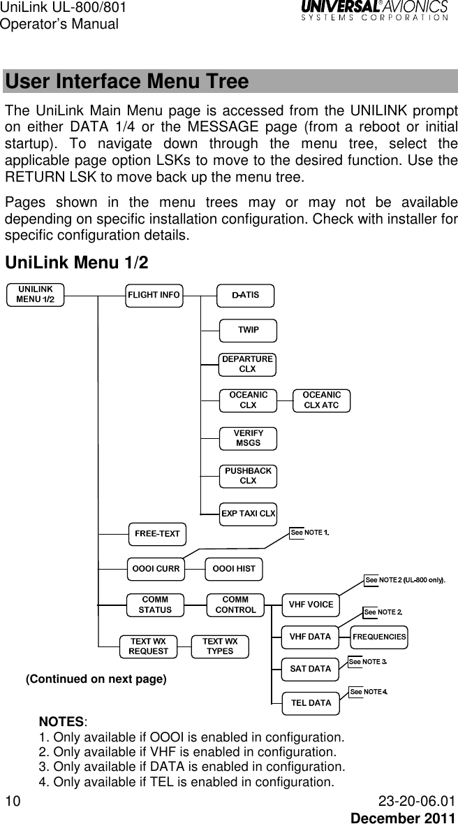
![UniLink UL-800/801 Operator’s Manual 23-20-06.01 15 December 2011 UNILINK MENU Menu Navigation: DATA (1/4) or MESSAGE 1/1 >UNILINK MENU 1/2 The UniLink Menu pages are accessed by selecting UNILINK from either DATA 1/4 page or the MESSAGE 1/X page. The DATA 1/4 page is accessed by pressing the [DATA] key. The MESSAGE 1/X page is accessed by pressing the [MSG] key. NOTE: Based on installation and configuration, the FLIGHT NO. field may or may not be displayed.](https://usermanual.wiki/Universal-Avionics-Systems/10801.Users-Manual-1/User-Guide-1641686-Page-25.png)
![UniLink UL-800/801 Operator’s Manual 16 23-20-06.01 December 2011 Flight Information Menu Navigation: UNILINK MENU 1/2 > FLIGHT INFO On the UNILINK MENU 1/2 Page, press FLIGHT INFO, LSK [1L], to access the FLIGHT INFO page. All services provided on this menu are available only over the ACARS VHF or SatCom packet data network. NOTE: Flight Information Services are advisory only. It is the responsibility of the pilot to exercise reasonable and prudent judgment in the use of these advisory services. NOTE: DEPARTURE, OCEANIC, PUSHBACK, and EXP TAXI requests are configurable options and are not displayed if configured as disabled. The aircraft tail number is automatically inserted in the CALL SIGN field. If the aircraft has a different ATS call sign assigned for the flight, it should be manually entered. To manually enter a callsign: 1. Press LSK [1R]. The CALLSIGN field will become active. 2. Enter the desired callsign using the alphanumeric keys. 3. Press [ENTER]. The new callsign will display in the field.](https://usermanual.wiki/Universal-Avionics-Systems/10801.Users-Manual-1/User-Guide-1641686-Page-26.png)
![UniLink UL-800/801 Operator’s Manual 23-20-06.01 17 December 2011 ATIS Request Menu navigation: UNILINK MENU 1/2 > FLIGHT INFO > D-ATIS The D-ATIS page is used to request local arrival or departure Automatic Terminal Information Service (ATIS). To request ATIS: 1. Press D-ATIS, LSK [1L] on the FLIGHT INFO page. The D-ATIS page will display. 2. With AIRPORT active, enter the Airport Identifier and press [ENTER], or accept the default destination airport from the FMS flight plan. NOTE: If an incomplete identifier is entered, the message TOO FEW CHARACTERS will display and the field will flash. Pressing the LSK and re-entering a complete identifier will correct the error. 3. DEPT is the default type of ATIS. Press TYPE, LSK [2R] to toggle the field between ARRV and DEPT as needed. 4. Press SEND, LSK [4R] to place the message in queue for transmission. NOTE: If the information on this page is incomplete, the pop-up window DATA REQUIRED will display and the SEND prompt will not enable.](https://usermanual.wiki/Universal-Avionics-Systems/10801.Users-Manual-1/User-Guide-1641686-Page-27.png)
![UniLink UL-800/801 Operator’s Manual 18 23-20-06.01 December 2011 TWIP Request Menu navigation: UNILINK MENU 1/2 > FLIGHT INFO > TWIP The TWIP page is used to request Terminal Weather Information for Pilots (TWIP). To make a TWIP request: 1. Press TWIP, LSK [2L] on the FLIGHT INFO page. The TWIP page will display. 2. With AIRPORT active, enter a destination airport and press [ENTER] or accept the Destination Airport from the FMS flight plan. NOTE: If an incomplete identifier is entered, the message TOO FEW CHARACTERS will display and the field will flash. Pressing the LSK and re-entering a complete identifier will correct the error. 3. Press the SEND LSK to place this message in queue for transmission. The SEND prompt will not be enabled if the information on this page is incomplete. NOTE: If the information on this page is incomplete, the pop-up window DATA REQUIRED will display and the SEND prompt will not enable.](https://usermanual.wiki/Universal-Avionics-Systems/10801.Users-Manual-1/User-Guide-1641686-Page-28.png)
![UniLink UL-800/801 Operator’s Manual 23-20-06.01 19 December 2011 Departure Clearance Request Menu navigation: UNILINK MENU 1/2 > FLIGHT INFO > DEPARTURE The DEPARTURE CLX page is used to request departure clearance. To request a Departure Clearance: 1. Press DEPARTURE, LSK [3L] on the FLIGHT INFO page. The DEPARTURE CLX page will display. 2. Verify or change the ORIG (origination) airport. This field defaults to the departure airport identifier from the FMS. 3. Verify or change the DEST (destination) airport. This field defaults to the destination airport from the FMS. 4. Enter GATE number (optional). 5. Press the REMARKS LSK to enter any remarks as needed (see the REMARKS Section in this manual). 6. Enter the latest ATIS version (alpha character). 7. Press SEND, LSK [4R] to place this message in queue for transmission. NOTE: The SEND prompt will not be enabled if the required information on this page is incomplete, the call sign from the Flight Information Services page is not entered, or the aircraft type has not been configured from Aircraft Configuration page. Any attempt to send this request with incomplete information will result in the pop-up window DATA REQURED displaying.](https://usermanual.wiki/Universal-Avionics-Systems/10801.Users-Manual-1/User-Guide-1641686-Page-29.png)
![UniLink UL-800/801 Operator’s Manual 20 23-20-06.01 December 2011 Oceanic Clearance Request Menu navigation: UNILINK MENU 1/2 > FLIGHT INFO > OCEANIC The OCEANIC CLX page is used to request Oceanic Clearance. To request an Oceanic Clearance: 1. Press OCEANIC, LSK [4L] on the FLIGHT INFO page. The OCEANIX CLX page will display. 2. Press ATC, LSK [1L] to open the OCEANIX CLX ATC page. 3. Select the ATC Station using the adjacent LSK, or enter a station ID in the OTHER field, LSK [R4]. The OCEANIX CLX page will display, showing the selected ATC station. 4. If not active, press ENTRY POINT, LSK [3L] and enter the point of entry into oceanic airspace, then press [ENTER}. NOTE: The Entry can have from 3 to 11 characters to specify the position by latitude/longitude, or by waypoint identifier. 5. If not active, press ENTRY TIME, LSK [3L] and enter the requested time for the clearance. Press [ENTER].](https://usermanual.wiki/Universal-Avionics-Systems/10801.Users-Manual-1/User-Guide-1641686-Page-30.png)
![UniLink UL-800/801 Operator’s Manual 23-20-06.01 21 December 2011 6. If not active, press MACH, LSK [2R] and enter the requested Mach number. Press [ENTER]. 7. If not active, press ALTITUDE, LSK [3R] and enter the requested flight level. Press [ENTER]. 8. Press REMARKS, LSK [4L] and enter any remarks as needed. OCEANIC Clearance remarks are entered using the OCEANIC CLX REMARKS page (see the REMARKS Page section in this manual). 9. Press SEND, LSK [4R] to place the message in queue for transmission. NOTE: If the information on this page is incomplete, a pop-up window DATA REQUIRED will display and the SEND prompt will not enable Verify Message Log Menu navigation: UNILINK MENU (1/2) > FLIGHT INFO > VERIF MSG LOG The VERIF MSGS page displays all verified uplink and downlink messages and can be used to check the queue status of sent messages. See VERIF MSG LOG in the Message Logs section of this manual.](https://usermanual.wiki/Universal-Avionics-Systems/10801.Users-Manual-1/User-Guide-1641686-Page-31.png)
![UniLink UL-800/801 Operator’s Manual 22 23-20-06.01 December 2011 Pushback Clearance Request Menu navigation: UNILINK MENU 1/2 > FLIGHT INFO > PUSHBACK The PUSHBACK CLX page is used to request pushback clearance. To request Pushback Clearance: 1. Press PUSHBACK, LSK [3R] on the FLIGHT INFO page. The PUSHBACK CLX page will display. 2. Verify the ORIG (Origination) airport. Change by pressing ORIG, LSK [1L] (if not active) and entering a different airport. Press [ENTER]. 3. If not active, press DEST (Destination), LSK [2L] to enter the destination airport. Press [ENTER]. 4. If not active, press GATE, LSK [3L] to enter gate Information (optional). Press [ENTER]. 5. If not active, press SCHED DATE, LSK [1R] to enter the scheduled date (day). Press [ENTER]. NOTE: Default date is per GMT. 6. If not active, press SCHED TIME, LSK [2R] to enter the scheduled time. Press [ENTER]. 7. Press REMARKS, LSK [4L] to enter any remarks as needed (optional). Pushback remarks are entered using the PUSHBACK CLX REMARKS page (See the Remarks Page section in this manual). 8. Press SEND, LSK [4R] to place this message in queue for transmission.](https://usermanual.wiki/Universal-Avionics-Systems/10801.Users-Manual-1/User-Guide-1641686-Page-32.png)
![UniLink UL-800/801 Operator’s Manual 23-20-06.01 23 December 2011 Expected Taxi Clearance Request Menu navigation: UNILINK MENU (1/2) > FLIGHT INFO > EXP TAXI The EXP TAXI CLX is used to request an Expected Taxi Clearance. To request an Expected Taxi Clearance: 1. Press EXP TAXI, LSK [4R] on the FLIGHT INFO page. The EXP TAXI CLX page will display. 2. Verify the ORIG (Origination) airport. Change by pressing ORIG, LSK [1L] and entering a different airport. Press [ENTER]. 3. If not active, press DEST (Destination), LSK [2L] to enter the destination airport. Press [ENTER]. 4. If not active, press GATE, LSK [3L] to enter gate Information (optional). Press [ENTER]. 5. If not active, press SCHED DATE, LSK [1R] to enter the scheduled date (day). Press [ENTER]. NOTE: Default date is per GMT. 6. If not active, press SCHED TIME, LSK [2R] to enter the scheduled time. Press [ENTER]. 7. Press REMARKS, LSK [4L] to enter any remarks as needed (optional). Taxi Clearance remarks are entered using the EXP TAXI CLX REMARKS page (See the Remarks Page section in this manual). 8. Press SEND, LSK [4R] to place this message in queue for transmission.](https://usermanual.wiki/Universal-Avionics-Systems/10801.Users-Manual-1/User-Guide-1641686-Page-33.png)
![UniLink UL-800/801 Operator’s Manual 23-20-06.01 25 December 2011 2. Create a message using the alphanumeric keys and LSKs. • The [ + ] key inserts spaces in the text. • LSKs [1L] through [3L] provide special characters as indicated on the display. Pressing the specific LSK multiple times cycles through the displayed choices. To enter a special character several times in a row, select another key between special character LSK presses (example: to enter several periods in a row, press LSK [2L], then the right-arrow key (which does nothing), then [2R], then the right-arrow key, etc.). • The arrow LSKs ([1R] through [4R]) move the cursor position within text already entered. Text entered at the cursor position in front of other text is inserted and word wrapping will occur as necessary. • To start a new line of text, press [ENTER]; the cursor will start a new line of text. • The CLEAR LSK erases all entered text on the page. • The text automatically word wraps to the next line. • The number of pages in the message will increase as necessary to accommodate entered text. 3. When finished editing the text portion of the message, press RETURN, LSK [5R]. The entered text will display in the REMARKS field for review. NOTE: The REMARKS field displays the first 7 characters of entered text. A following ellipsis (…) indicates there is more text in the message. The REMARKS page allows review of the entire remarks text. 4. Press the SEND LSK to place the message in queue for transmission.](https://usermanual.wiki/Universal-Avionics-Systems/10801.Users-Manual-1/User-Guide-1641686-Page-35.png)
![UniLink UL-800/801 Operator’s Manual 26 23-20-06.01 December 2011 FREE-TEXT – Create and Send a Message Menu navigation: UNILINK MENU 1/2 > FREE TEXT The FREE-TEXT option is available at LSK [2L] on the UNILINK MENU 1/2 page. The FREE TEXT page allows the user to create and edit text messages. Create and Send a Message 1. Press FREE-TEXT, LSK [2L] on the UNILINK MENU 1/2 page. 2. With the TO field active, enter the destination identifier. Press [ENTER]. 3. Enter the destination/recipient telephone number (if known) in the NO: field and press [ENTER]. Pressing [ENTER] moves the cursor to the first text line of the TEXT EDIT page. NOTE: Pressing LSK [2L] will also bring up the TEXT EDIT page.](https://usermanual.wiki/Universal-Avionics-Systems/10801.Users-Manual-1/User-Guide-1641686-Page-36.png)
![UniLink UL-800/801 Operator’s Manual 23-20-06.01 27 December 2011 4. Create a message using the alphanumeric text option keys. • The [ ± ] key is used to insert a space. • The text automatically word wraps to the next line. • The number of pages in the message will increase as necessary to accommodate entered text. • The left LSKs are used to insert special characters as indicated on the display. Selecting the same special character key multiple times will cause the selected character to cycle between the three displayed choices. • The right line select keys are used to move the cursor (+) position within the text that has been entered. • Any text entered at the cursor position in front of other text will be inserted and word wrapping will automatically occur as necessary. • To start a new line of text, press [ENTER] and the cursor (+) will start a new line of text. 5. When finished editing the text portion of the message, press RETURN, LSK [5R]. The entered text is displayed on the FREE TEXT page for review with additional pages added as necessary. 6. Press SEND to place the message in queue for transmission. QUEUED will display above the SEND option to indicate the message is in queue. Send a Message to another Aircraft 1. On the Free Text page, enter the destination registry in the TO field and press [ENTER]. 2. Enter the letter “A” in the first position of the NO field followed by the registry of the destination aircraft and press [ENTER]. 3. Enter the message text in the free text area. When finished editing the text portion of the message, press RETURN, LSK [5R]. The entered text is displayed on the FREE TEXT page for review with additional pages added as necessary. 4. Press SEND, LSK [4R] to place the message in queue for transmission.](https://usermanual.wiki/Universal-Avionics-Systems/10801.Users-Manual-1/User-Guide-1641686-Page-37.png)
![UniLink UL-800/801 Operator’s Manual 28 23-20-06.01 December 2011 Send an E-Mail NOTE: Arrangement with DSP must be made for e-mail capability to be available. Specific detailed instructions for email operation may differ from the following procedure, depending on the service provider. 1. With the TO line active, press [ENTER] to make the NO field active. 2. Enter "E" in the first position of the NO field and press [ENTER]. 3. In the free text area, enter the destination e-mail address. Use DA for a dash (-), DOT for dot (.) and AT for at symbol (@). Delimit the address with ST (Example: SCOTT AT AOL DOT COM ST). Use spaces as indicated in the example and press [ENTER]. NOTE: The message will not send if symbols are used in place of text (i.e., DA, DOT, AT). NOTE: Spaces are placed in text using the plus/minus ( [ + ] ) key. 4. Enter the message text beginning on the next line after ST. NOTE: If previously entered text is still in the Free-Text area, press CLEAR, LSK [4L] before entering new text. 5. When finished editing the text portion of the message, press RETURN, LSK [5R]. The entered text is displayed on the FREE TEXT page for review with additional pages added as necessary. 6. Press SEND, LSK [4R] to place the message in queue for transmission. A confirmation message will display if the e-mail is sent successfully.](https://usermanual.wiki/Universal-Avionics-Systems/10801.Users-Manual-1/User-Guide-1641686-Page-38.png)
![UniLink UL-800/801 Operator’s Manual 23-20-06.01 29 December 2011 Send a Fax 1. On the FREE TEXT page, enter the fax recipient in the TO field and press [ENTER]. 2. In the NO field, enter the letter “F” followed by the destination fax number with no spaces. Include: country code, area code, fax number (Example: F17139434610) and press [ENTER]. 3. Enter the message text in the free text area. When finished editing the text portion of the message, press RETURN, LSK [5R]. The entered text is displayed on the FREE TEXT page for review with additional pages added as necessary. 4. Press SEND, LSK [4R] to place the message in queue for transmission. Send a Page to a Skytel Pager (Skytel Customers Only) 1. Enter “P” followed by the Skytel Pager PIN number, (no spaces) in the NO field and press [ENTER]. 2. Enter the message text in the free text area. When finished editing the text portion of the message, press RETURN, LSK [5R]. The entered text is displayed on the FREE TEXT page for review with additional pages added as necessary. 3. Press SEND, LSK [4R] to place the message in queue for transmission.](https://usermanual.wiki/Universal-Avionics-Systems/10801.Users-Manual-1/User-Guide-1641686-Page-39.png)
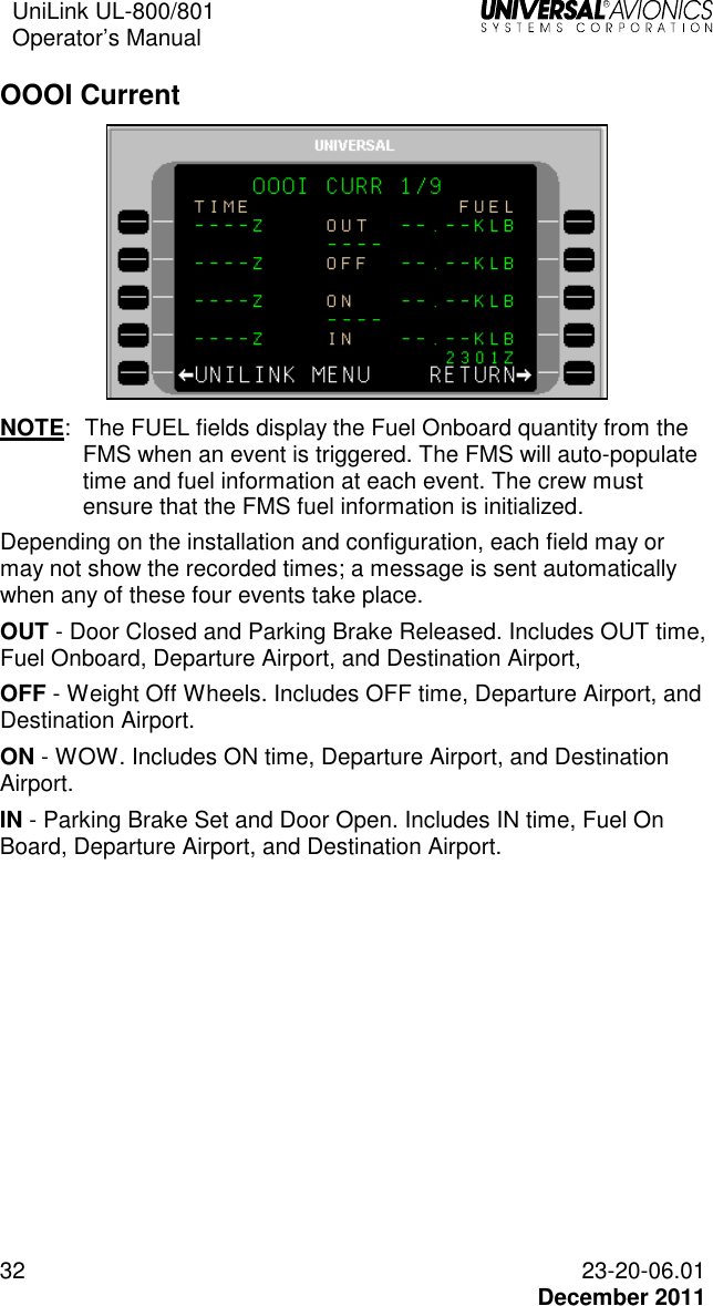
![UniLink UL-800/801 Operator’s Manual 30 23-20-06.01 December 2011 OOOI Menu Navigation: UNILINK MENU 1/2 > OOOI OOOI pages record data about the current flight and flight history. The OOOI option is available (if configured) at LSK [3L] on the UNILINK MENU 1/2 page. OOOI Operation OOOI (Out, Off, On, In) reports allow a dispatch or schedule office to track a flight as well as provide accurate flight times and block times. Based on installation, UniLink may use inputs from one or more doors, the parking brake, and weight-on-wheels (WOW) status input. OOOI reports may also use digital inputs from devices such as the FMS or configured Input/Output Processors (IOP). UniLink monitors the state of each discrete and the WOW condition at power-up, but does not issue any reports unless a change in state is detected. The OUT requirement is met when all doors are closed and then the parking brake is released. The ideal sequence is: 1) UniLink powered up with brake set and doors open 2) Doors closed 3) Brake released 4) OUT report generated Once the OUT report has been generated, if the door happens to be opened prior to takeoff, an OUT/RETURN IN report will be generated. Once an OUT report is generated (and the door remains closed) a change in the WOW status from on-ground to in-air will result in an OFF report. If UniLink is powered up or reset in flight, it will monitor the WOW state, determine that the aircraft is airborne and ignore all changes in status of doors and brakes. A change to the WOW status from in-air to on-ground will result in the ON report. For an IN report to be generated, UniLink must: • detect an OUT transition • detect an OFF transition • detect an ON transition](https://usermanual.wiki/Universal-Avionics-Systems/10801.Users-Manual-1/User-Guide-1641686-Page-40.png)
![UniLink UL-800/801 Operator’s Manual 23-20-06.01 31 December 2011 • and then detect that the door is opened The IN time that is recorded for the IN event is the last time the brake was set prior to the door opening, or the time that the door opens if the brake was not set. The time for all other OOOI events is the time that the UniLink detected the last state change required for the transition to occur. Ground Delay (Optional) To determine OOOI status, navigate to the SENSORS 1/2 page. A GROUND DELAY ADVISORY occurs when the configured time on the Ground Delay Timer expires after doors closed /brakes released (OUT event) but before Weight-Off-Wheels/Takeoff (OFF event). The GROUND DELAY ADVISORY annunciation will display at LSK [5L]. Pressing LSK [5L] will display the DELAY page. The crew can send a ground delay report by following the procedure listed in the DELAY section of this manual.](https://usermanual.wiki/Universal-Avionics-Systems/10801.Users-Manual-1/User-Guide-1641686-Page-41.png)
![UniLink UL-800/801 Operator’s Manual 23-20-06.01 33 December 2011 OOOI History The OOOI event history is captured at the start of the flight. The most recently stored event is displayed on OOOI HIST 2/9 page. The next most recent is displayed on OOOI HIST 3/9. A maximum of nine OOOI HIST pages are available. OOOI HIST is accessed from the OOOI page by pressing the [PREV] or [NEXT] keys. OOOI data is retained during a power cycle.](https://usermanual.wiki/Universal-Avionics-Systems/10801.Users-Manual-1/User-Guide-1641686-Page-43.png)
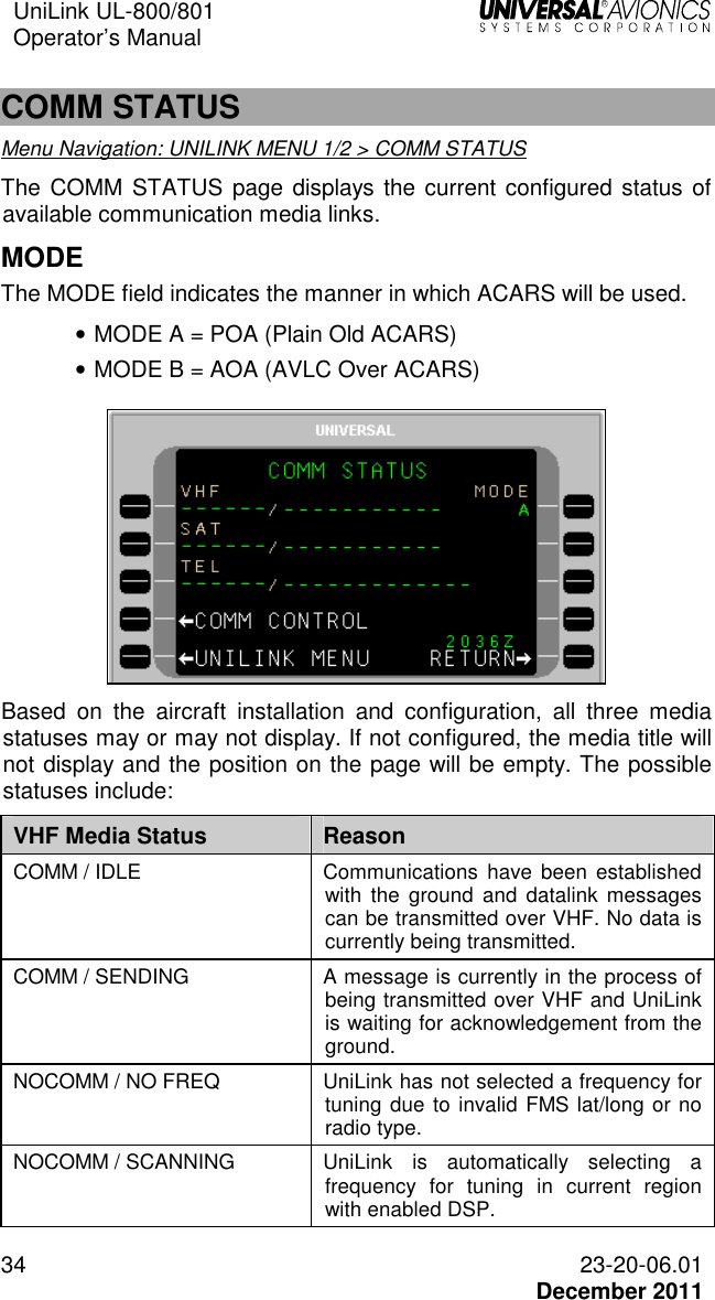
![UniLink UL-800/801 Operator’s Manual 38 23-20-06.01 December 2011 COMM CONTROL Menu Navigation: UNILINK MENU 1/2 > COMM STATUS > COMM CONTROL The COMM CONTROL page provides access to media control pages and options. Access the COMM CONTROL page by selecting COMM STATUS, LSK [3L] from the UNILINK MENU 1/2 page. Then select COMM CONTROL, LSK [4L] from the COMM STATUS page to display the COMM CONTROL page. The COMM CONTROL page gives access to VHF VOICE (UL-800 only), VHF DATA, SAT DATA, and TEL DATA options (as configured and installed) UL-800 with External VDR UL-801 with Internal VDR VHF Voice (UL-800 only) Menu Navigation: UNILINK MENU 1/2 > COMM STATUS > COMM CONTROL > VHF VOICE The VHF VOICE option is available if the VHF radio supports voice communications (does not apply to UL-801 with internal VDR).](https://usermanual.wiki/Universal-Avionics-Systems/10801.Users-Manual-1/User-Guide-1641686-Page-48.png)
![UniLink UL-800/801 Operator’s Manual 23-20-06.01 39 December 2011 Pressing VHF VOICE, LSK [1L] from the COMM CONTROL page displays the VHF VOICE page. UL-800 with External VDR The VHF VOICE page is used to enable/disable VHF voice mode. LSKs [1R] and [2R] allow selection of the MODE as either DATA or VOICE respectively (an asterisk <*> indicates the selected mode). DATA Mode - UniLink data communication; no voice communications. UniLink will tune to the appropriate datalink frequencies only. VOICE Mode - UniLink no longer communicates via VHF to support datalink communications. The external VDR is used for voice and voice frequencies are tuned via VOICE FREQ, LSK [3L]. VHF voice frequency can be tuned from this page if Voice Frequency Control enabled in configuration. Valid frequency range is: • If configured for frequency spacing of 25KHz - 118.000 to 136.950 • If configured for frequency spacing of 25KHz/8.33KHz - 118.000 to 136.965 and 136.980 to 136.990 NOTE: The frequency 136.975 is a reserved frequency.](https://usermanual.wiki/Universal-Avionics-Systems/10801.Users-Manual-1/User-Guide-1641686-Page-49.png)
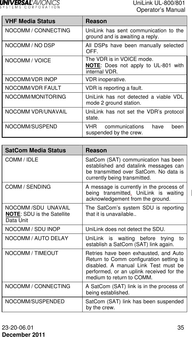
![UniLink UL-800/801 Operator’s Manual 40 23-20-06.01 December 2011 VHF Data Menu Navigation: UNILINK MENU 1/2 > COMM STATUS > COMM CONTROL > VHF DATA The VHF DATA option is available if a VHF radio is configured. The VHF DATA page allows the user to enable or disable the individual DSPs and provides access to the VHF Frequency (FREQUENCIES) page. On the COMM CONTROL page press VHF DATA, LSK [2L] to access the VHF DATA page. Pressing the LSK adjacent to each DSP toggles the network status between DISABLED and ENABLED. In the ENABLED status, UniLink will communicate with the service provider as appropriate. The DISABLED status prohibits communications with the provider. If all Service Providers are selected to DISABLED, the VHF status displayed on the COMM STATUS page will reflect NOCOMM/NO DSP. To resolve a VHF NOCOMM problem: 1. On the VHF DATA page, ensure VHF STATE is not set to SUSPEND. 2. Press LINK TEST SEND. This will initiate a link test to reestablish VHF communications. Communications should be reestablished within approximately one minute and the NOCOMM advisory should no longer be displayed. If NOCOMM continues to be displayed, this may indicate an equipment or VHF system network failure not associated with incorrect frequency usage.](https://usermanual.wiki/Universal-Avionics-Systems/10801.Users-Manual-1/User-Guide-1641686-Page-50.png)
![UniLink UL-800/801 Operator’s Manual 42 23-20-06.01 December 2011 FREQUENCIES Menu Navigation: UNILINK MENU 1/2 > COMM STATUS > COMM CONTROL > VHF DATA > FREQUENCIES The FREQUENCIES page is accessed by selecting the FREQUENCIES, LSK [3R] on the VHF DATA page. The FREQUENCIES page displays the primary frequency table and a field for secondary frequency selection. Normal frequency selection is controlled automatically by UniLink management logic and user intervention is not required. If the UniLink Geographic Database indicates that a DSP has coverage on a particular frequency at the aircraft’s current location, the DSP’s name will be displayed above the frequency (ARINC, SITA, AVICOM, or MULTIPLE). Otherwise NO CVG (No Coverage) will display. LSKs allow manual selection of a primary frequency. The <*> icon indicates the frequency that is currently tuned. The secondary frequency may be manually entered or uplinked from the ground. Any entry in the range of 118.000 through 136.975 will be accepted. Only one frequency, primary or secondary, can be selected at a time.](https://usermanual.wiki/Universal-Avionics-Systems/10801.Users-Manual-1/User-Guide-1641686-Page-52.png)
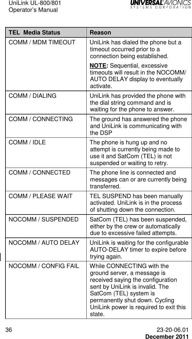
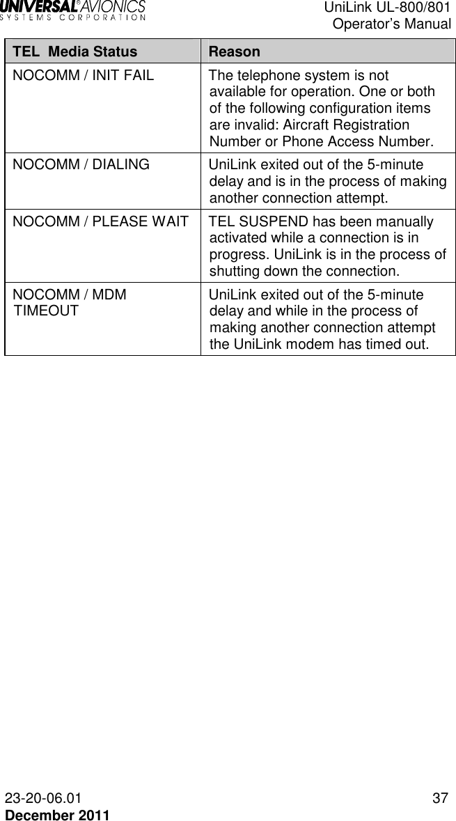
![UniLink UL-800/801 Operator’s Manual 23-20-06.01 43 December 2011 TEL DATA Menu Navigation: UNILINK MENU 1/2 > COMM STATUS > COMM CONTROL > TEL DATA The TEL DATA page is available if an air phone is configured. The TEL DATA page displays the DSP configured telephone number and also allows manual override with a different number. To override the configured telephone number, press NUMBER, LSK [3L]. This highlights the NUMBER field and allows the displayed number to be edited or a new number to be entered. An entry of up to 19 digits is acceptable. The new entry will remain active until the system is restarted, or the number may be restored to the configured value by pressing the [BACK], then [ENTER] keys. From the CDU/MCDU keyboard enter P for pause, L for #, or A for *. Contact your DSP for the appropriate telephone number. When the SUSPEND option is selected, telephone communication is suspended and no datalink messages can be sent via telephony. When RESUME is selected, the telephone can be used for sending messages. The SUSPEND option is automatically selected if there have been excessive unsuccessful attempts at sending messages via telephony to the ground. Any manual selection will override any automatically set condition. A <*> indicates the current state STATE • RESUME: When selected, <*> will display. This allows the TEL system to resume operation. • SUSPEND: When selected, <*> will display. This suspends the system. While suspended, no TEL transmissions will be permitted by UniLink and no TEL uplink messages will be processed.](https://usermanual.wiki/Universal-Avionics-Systems/10801.Users-Manual-1/User-Guide-1641686-Page-53.png)
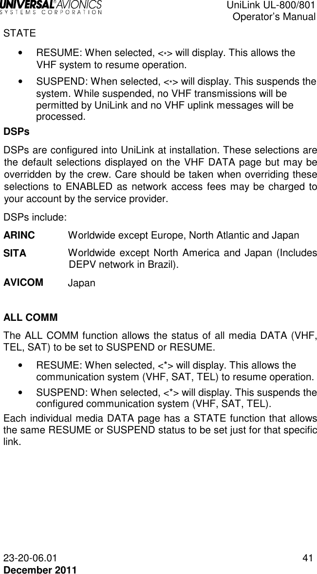
![UniLink UL-800/801 Operator’s Manual 44 23-20-06.01 December 2011 Telephone Link Test This feature provides the operator the ability to test the telephone link by sending a downlink over the telephone system and then displays the link test status. Run the test by selecting LINK TEST SEND, LSK [4R]. The state of the telephone link test will display on the line above. Once the test is complete, the telephone status is displayed on the COMM STATUS page. The displayed status is described in the COMM Status section of this manual. SAT DATA Menu Navigation: UNILINK MENU 1/2 > COMM STATUS > COMM CONTROL > SAT DATA The SAT DATA page allows the user to send a SatCom link test. SatCom Datalink Test This feature provides the operator the ability to test the SatCom link by sending a downlink over the SatCom system and then display the link test status. Run the test by selecting LINK TEST SEND, LSK [4R]. While the test is running, the state of the SatCom link test is displayed on the line above. Once the test is complete, the SatCom status is displayed on the COMM STATUS page. The displayed status is described in the COMM Status section of this manual. STATE • RESUME: When selected, <*> will display. This allows the SAT system to resume operation. • SUSPEND: When selected, <*> will display. This suspends the SAT system. While suspended, no SAT transmissions will be permitted by UniLink and no VHF uplink messages will be processed.](https://usermanual.wiki/Universal-Avionics-Systems/10801.Users-Manual-1/User-Guide-1641686-Page-54.png)
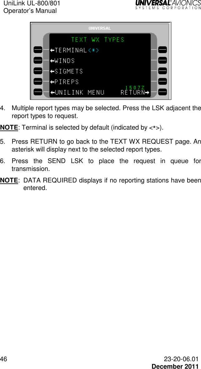
![UniLink UL-800/801 Operator’s Manual 23-20-06.01 45 December 2011 Text Weather Report Requests Menu Navigation: UNILINK MENU 1/2 > TEXT WX > TEXT WX REQUEST The TEXT WX REQUEST page allows the user to request four types of text weather reports from up to six locations. TERMINAL weather received from this request will apply to stations entered on this page, and will include both actual and forecast conditions for each station. WINDS (Winds Aloft), SIGMETS (Significant Meteorological information), and PIREPS (Pilot Weather Reports), and will apply to the flight plan route from the FMS. If a manual data entry is made in STATIONS fields (LSKs [1L & 2L]), the Winds Aloft will apply to waypoints along the great circle route from the aircraft’s present position to the airport identifier. Stored text weather messages are accessed via the VERIF OPS WX page (accessed from the MESSAGE LOGS page). To request Text Weather: 1. Press TEXT WX, LSK [1R] on UNILINK MENU 1/2 page. 2. On the TEXT WX REQUEST page, enter up to six reporting stations (STATIONS) using LSKs [1L] and [2L], and then press the [ENTER] key. The first station will default to the FMS destination airport identifier. NOTE: When exiting this page, all stations entered are cleared. 3. Press TYPES, LSK [1R] to choose the type of reports to receive. The WX TYPE SELECT page will display.](https://usermanual.wiki/Universal-Avionics-Systems/10801.Users-Manual-1/User-Guide-1641686-Page-55.png)
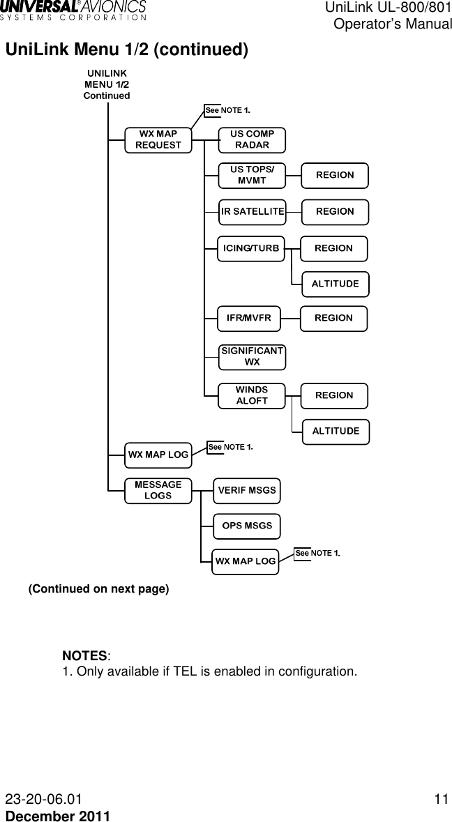
![UniLink UL-800/801 Operator’s Manual 23-20-06.01 47 December 2011 Weather Map Requests Menu Navigation: UNILINK MENU 1/2 > WX MAPS The UNILINK MENU 1/2 page allows the user to request and view graphical weather maps. Maps are available only over an airborne telephony link and the WX MAP REQUEST page is only available when the WX MAPS configuration selection is enabled. Graphic weather maps are available on Flat Panel Control Display Units (FPCDU) having graphics capability. NOTE: WX MAP REQUEST page can be accessed either from UNILINK MENU 1/2 (WX MAPS, LSK [2R]) or the WX MAPS LSK on the TEXT WX REQUEST page. US Composite Radar Menu Navigation: UNILINK MENU (1/2) > WX MAPS> COMP RADAR The US COMP RADAR page allows the user to request Composite Radar Weather maps at specified weather stations and International Civil Aviation Organization (ICAO) airports.](https://usermanual.wiki/Universal-Avionics-Systems/10801.Users-Manual-1/User-Guide-1641686-Page-57.png)
![UniLink UL-800/801 Operator’s Manual 48 23-20-06.01 December 2011 To request a Composite Radar graphic: 1. Press COMP RADAR, LSK [1L] on the WX MAP REQUEST page. The US COMP RADAR page will display. 2. Enter an airport identifier in the STATION field and press [ENTER], or accept the default destination airport identifier from the FMS. NOTE: If an incomplete identifier is entered, the message TOO FEW CHARACTERS will display and the field will flash. Pressing the LSK and re-entering a complete identifier will correct the error. 3. Select a Map Range using the range LSK options. A <*> indicator will display adjacent to the selected range. NOTE: The selected range is retained through system power cycles. 4. Press SEND, LSK [4R] to place the request in queue for transmission. NOTE: The SEND LSK will not be active and DATA REQUIRED displays if no airport identifier has been entered. US Radar Tops and Movement Menu Navigation: UNILINK MENU 1/2 > WX MAPS > TOPS/MVMT The US TOPS/ MVMT page is used to request US Radar Tops and Movement graphics from a specific geographical area.](https://usermanual.wiki/Universal-Avionics-Systems/10801.Users-Manual-1/User-Guide-1641686-Page-58.png)
![UniLink UL-800/801 Operator’s Manual 23-20-06.01 49 December 2011 To request a Tops and Movement graphic: 1. Press TOPS/ MVMT, LSK [2L] on the WX MAP REQUEST page. The US TOPS/MVMT page will display 2. Press REGION, LSK [2L] to display the REGION- US TOPS/MVMT page. 3. Select a region LSK option for display and return to the US TOPS/MVMT page. The last selection will remain through system power cycles. 4. Press the SEND LSK to place the request in queue for transmission.](https://usermanual.wiki/Universal-Avionics-Systems/10801.Users-Manual-1/User-Guide-1641686-Page-59.png)
![UniLink UL-800/801 Operator’s Manual 50 23-20-06.01 December 2011 IR SATELLITE Menu Navigation: UNILINK MENU 1/2 > WX MAPS > IR SAT The IR SATELLITE page allows the user to request worldwide IR Satellite Weather maps. To request an IR Satellite Map graphic: 1. Press IR SAT, LSK [3R] on the WX MAP REQUEST page. The IR SATELLITE page will display. 2. Press REGION, LSK [2L] to display the REGION-IR SATELLITE 1/2 page. If needed, press NEXT to display the REGION-IR SATELLITE 2/2 page. 3. Select a region for display and return to the IR SATELLITE page. The last selection will remain through system power cycles. 4. Press the SEND LSK to place the request in queue for transmission.](https://usermanual.wiki/Universal-Avionics-Systems/10801.Users-Manual-1/User-Guide-1641686-Page-60.png)
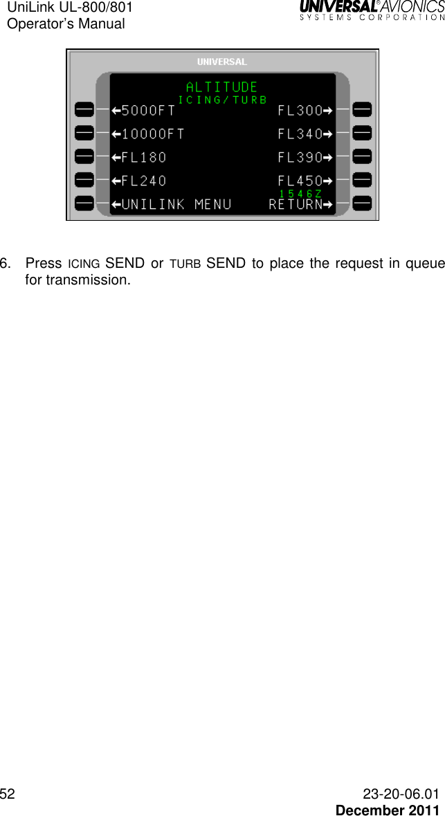
![UniLink UL-800/801 Operator’s Manual 23-20-06.01 51 December 2011 Icing/Turbulence Potential Menu Navigation: UNILINK MENU 1/2 > WX MAPS > ICING/TURB The ICING TURB page is used to request worldwide icing potential or turbulence potential maps. To request an Icing Potential or Turbulence Potential Map: 1. Press ICING/TURB, LSK [4L] on the WX MAP REQUEST page. The ICING/TURB page will display. 2. Press REGION, LSK [2L] to display the REGION-ICING TURB page. 3. Select a region for display and return to the ICING/TURB page. The last selection will remain through system power cycles. 4. Press ALTITUDE to access the ALTITUDE-ICING/TURB page. 5. Select an altitude option by pressing the adjacent LSK and return to the ICING/TURB page. The last selection will remain through system power cycles.](https://usermanual.wiki/Universal-Avionics-Systems/10801.Users-Manual-1/User-Guide-1641686-Page-61.png)
![UniLink UL-800/801 Operator’s Manual 23-20-06.01 53 December 2011 IFR/MVFR Menu Navigation: UNILINK MENU 1/2 > WX MAPS > IFR/MVFR The IFR/MVFR page is used to request worldwide IFR/MVFR maps. To request an IFR/MVFR Map: 1. Press IFR/MVFR, LSK [1R] on the WX MAP REQUEST page. The IFR/MVFR page will display. 2. Press REGION, LSK [2L] to display REGION-IFR/MVFR page. 3. As needed, press the [NEXT] key to display the REGION 2/3 and 3/3 pages. Select a region and return to the IFR/MVFR page. NOTE: The last selection will be retained through system power cycles. 4. Press SEND, LSK [4R] to place the request in queue for transmission.](https://usermanual.wiki/Universal-Avionics-Systems/10801.Users-Manual-1/User-Guide-1641686-Page-63.png)
![UniLink UL-800/801 Operator’s Manual 54 23-20-06.01 December 2011 Significant Weather Menu Navigation: UNILINK MENU 1/2 > WX MAPS > SIG WX The SIGNIFICANT WX page allows the user to request High Level Significant Weather Maps. To request a Significant Weather Map: 1. Press SIG WX, LSK [2R] on the WX MAP REQUEST page. The SIGNIFICANT WX page will display. 2. Press REGION, LSK [2L] to display the REGION-SIGNIFICANT WX 1/2 page. 3. As needed, press NEXT to display REGION-SIGNIFICANT WX 2/2 page. Select a region for display and return to the Significant Weather page. The last selection will remain through system power cycles. 4. Press SEND, LSK [4R] to place the request in queue for transmission.](https://usermanual.wiki/Universal-Avionics-Systems/10801.Users-Manual-1/User-Guide-1641686-Page-64.png)
![UniLink UL-800/801 Operator’s Manual 23-20-06.01 55 December 2011 Winds Aloft Menu Navigation: UNILINK MENU 1/2 > WX MAPS > WINDS ALOFT The WINDS ALOFT page allows the user to request the most current worldwide Winds Aloft maps by region. To request The Winds and Temperature Aloft graphic: 1. Press WINDS ALOFT, LSK [3R] on the WX MAPS REQUEST page. The WINDS ALOFT page will display. 2. Press REGION, LSK. [2L]. The REGION-WINDS ALOFT 1/3 page will display. 3. As needed, press the [NEXT] key to display the REGION-WINDS ALOFT pages 2/3 and 3/3. Select a region for display by pressing the adjacent LSK and return to the WINDS ALOFT page. The last selection will remain through system power cycles. 4. Press the ALTITUDE LSK to access the ALTITUDE-WINDS ALOFT 1/2 page.](https://usermanual.wiki/Universal-Avionics-Systems/10801.Users-Manual-1/User-Guide-1641686-Page-65.png)
![UniLink UL-800/801 Operator’s Manual 56 23-20-06.01 December 2011 5. As needed, press the [NEXT] key to display ALTITUDE-WINDS ALOFT page 2/2. Select an altitude by pressing the adjacent LSK and return to the WINDS ALOFT page. The last selection will remain through system power cycles. 6. Press the SEND LSK to place the message in queue for transmission.](https://usermanual.wiki/Universal-Avionics-Systems/10801.Users-Manual-1/User-Guide-1641686-Page-66.png)
![UniLink UL-800/801 Operator’s Manual 23-20-06.01 57 December 2011 Weather Map Log Menu Navigation: UNILINK MENU 1/2 > WX MAP LOG The WX MAP LOG pages allow the user to select previously uplinked weather graphics for viewing on a CDU/MCDU, MFD, EFI-890R, or for deletion. Weather map titles are listed in the order they are received with the last map received appearing first. UniLink stores up to 32 maps. NOTE: The WX MAP LOG page can be accessed from UNILINK MENU 1/2, TEXT WX REQUEST page, or WX MAP REQUEST page. To display a weather map: 1. Press the WX MAP LOG, LSK [4R] on the WX MAP REQUEST page, LSK [3R] on UNILINK MENU 1/2 page, or LSK [4L] on the TEXT WX REQUEST page. 2. Press the left-hand LSK adjacent the desired weather map. NOTE: Pressing any key while the map is displayed will return the display to the MAP LOG page. To display a new weather map after receiving a NEW WX MAP RCVD message: 1. Press the UNILINK LSK on the DATA 1/X page or the MESSAGE 1/X page to access the UNILINK MENU page. 2. Press NEW WX MAP advisory prompt to view the weather map.](https://usermanual.wiki/Universal-Avionics-Systems/10801.Users-Manual-1/User-Guide-1641686-Page-67.png)
![UniLink UL-800/801 Operator’s Manual 23-20-06.01 59 December 2011 Message Logs Menu Navigation: UNILINK MENU 1/2 > MSG LOGS The MESSAGE LOGS page allows the user to view, print, or delete messages. Verified Messages – The VERIF MSGS 1/X page displays all ATS or other verified messages. Press VERIF MSG LOG, LSK [1R] to access the VERIF MSGS page. Operations Messages – The OPS MSGS 1/X page displays all unverified messages (messages containing unverified data). Press OPS MSG LOG, LSK [2R] to access the OPS MSGS page. WX Map Uplinks – The WX MAP LOG 1/X page displays all weather graphic uplinks. Press WX MAP LOG, LSK [3R] to access the WX MAP LOG pages. Message titles will appear on these pages in the inverse order they are received. The newest message will appear first. If more than one page of message titles exists, use the [PREV] and [NEXT] keys to cycle through the pages. A new message may be viewed from any UNILINK page by pressing the NEW MSG ADVISORY LSK. Messages may be viewed by selecting the left-hand LSK adjacent the message title. To delete all messages from a message log, press the DELETE ALL LSK. This prompt is only displayed on page 1 of the message log pages.](https://usermanual.wiki/Universal-Avionics-Systems/10801.Users-Manual-1/User-Guide-1641686-Page-69.png)
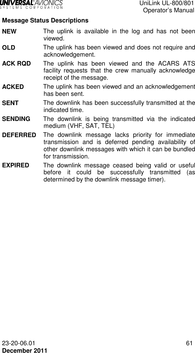
![UniLink UL-800/801 Operator’s Manual 60 23-20-06.01 December 2011 Verified Messages Menu Navigation: UNILINK MENU 1/2 > MSG LOGS > VERIF MSG LOG The VERIF MSGS page displays all ATS, Clearance, and other verified messages. Press VERIF MSG LOG, LSK [1R] to access the VERIF MSGS page. The total number of pages increases as verified messages are received. If more than one page of message titles exists, use the [PREV] and [NEXT] keys to cycle through the pages. LSKs [1L] through [3L] on page 1/X and [1L] through [4L] on succeeding pages display ATS and other verified message titles. Status information is displayed above the message title and includes the time received, transmission medium, uplink (¨) or downlink (Î) indicator, and status. Messages are sorted with the newest at the top of the list. Pressing the left-hand LSK adjacent a message displays the corresponding message if the message contains viewable text. Pressing a right-hand LSK displays the message pop-up window for the corresponding message and allows the deletion or printing of the message (see the Delete or Print a Message section later in this manual). Any key press other than [1R] or [2R] will exit the pop-up window. DELETE ALL, LSK [4L] on page 1/X is used to delete all uplinked messages from the displayed page. RETURN, LSK [5R] returns the display to the MESSAGE LOGS page.](https://usermanual.wiki/Universal-Avionics-Systems/10801.Users-Manual-1/User-Guide-1641686-Page-70.png)
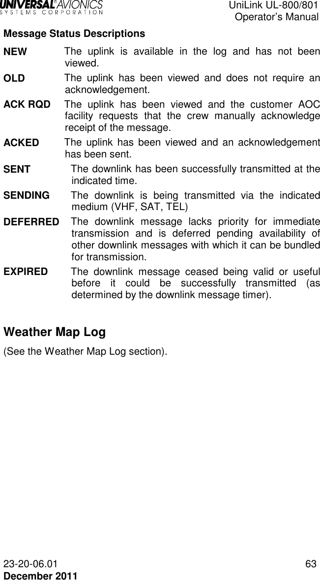
![UniLink UL-800/801 Operator’s Manual 62 23-20-06.01 December 2011 Operations Messages Menu Navigation: UNILINK MENU(1/2 > MSG LOGS > OPS MSG LOG The OPS MSGS page displays all operations unverified uplink messages including Text Weather and Free Text. Press OPS MSG LOG, LSK [2R] to access the OPS MSGS page. The total number of pages increases as uplink messages are received. If more than one page of message titles exists, use the [PREV] and [NEXT] keys to cycle through the pages. LSKs [1L] through [3L] on page 1/X and [1L] through [4L] on succeeding pages display unverified uplink message titles. Status information is displayed above the message title and includes the time received, transmission medium, uplink (¨) or downlink (Î) indicator, and status. Messages are sorted with the newest at the top of the list. Pressing a left-hand LSK displays the OPS MSG page for the corresponding message if the message contains viewable text. Pressing a right-hand LSK displays the message pop-up window for the corresponding message and allows the deletion or printing of the message (see the Delete or Print a Message section later in this manual). Any key press other than [1R] or [2R] will exit the pop-up window. DELETE ALL, LSK [4L] on page 1/X is used to delete all messages from the log. RETURN, LSK [5R] returns the display to the MESSAGE LOGS page.](https://usermanual.wiki/Universal-Avionics-Systems/10801.Users-Manual-1/User-Guide-1641686-Page-72.png)
![UniLink UL-800/801 Operator’s Manual 64 23-20-06.01 December 2011 View Message - Detailed Message Screen A detailed message screen will display when a message is viewed by selecting a corresponding message LSK or via the NEW MESSAGE ADVISORY. 1. Press the [PREV] and [NEXT] keys to cycle through the pages. 2. In the message log page (VERIF MSGS, OPS MSGS, or WX MAP LOG), press the left LSK adjacent a message title to view a message. A detailed message screen or weather graphic will display.](https://usermanual.wiki/Universal-Avionics-Systems/10801.Users-Manual-1/User-Guide-1641686-Page-74.png)
![UniLink UL-800/801 Operator’s Manual 23-20-06.01 65 December 2011 Delete or Print a Message NOTE: This procedure is available on the VERIF MSGS, OPS MSGS, and WX MAP LOG pages. 1. Access the desired message log page. 2. Press the right-hand LSK of a message. This activates the message pop-up window. 3. Press the PRINT LSK to print the message (a printer must be installed and configured). 4. Press the DELETE LSK to delete the message. 5. Press the CANCEL LSK to exit the pop-up menu. NOTE: Any LSK or CDU keyboard selection other than LSKs [1R] or [2R] removes the pop-up window.](https://usermanual.wiki/Universal-Avionics-Systems/10801.Users-Manual-1/User-Guide-1641686-Page-75.png)
![UniLink UL-800/801 Operator’s Manual 66 23-20-06.01 December 2011 DELAY Menu Navigation: UNILINK MENU 2/2 > DELAY The DELAY page is used to report estimated ground delays prior to take off. To send a Ground Delay report: 1. Press DELAY, LSK [1L] from UNILINK MENU page 2/2 or from any page when selecting the GROUND DELAY advisory. 2. With EST DELAY (estimated delay) active, enter the estimated time in minutes and press [ENTER]. 3. Press REASON, LSK [1R] to access the DELAY REASON page. 4. Press the LSK adjacent the appropriate reason option. The display will return to the DELAY page. NONE will be selected by default if no entry is made on this page. 5. Press SEND, LSK [4R] to place the message in queue for transmission.](https://usermanual.wiki/Universal-Avionics-Systems/10801.Users-Manual-1/User-Guide-1641686-Page-76.png)
![UniLink UL-800/801 Operator’s Manual 23-20-06.01 67 December 2011 DIVERSION Menu Navigation: UNILINK MENU 2/2 > DIVERSION The DIVERSION page is used to send a revised destination message. To send a diversion message: 1. Press DIVERSION, LSK [2L] from UNILINK MENU page 2/2. The DIVERSION page will display. 2. With NEW DEST active, enter a destination and press [ENTER] or verify new destination data from the FMS. 3. If not active, press ETA (LSK [3L]), enter an ETA, and press [ENTER]; or verify ETA data from the FMS. 4. Press REASON, LSK [1R] to access the DIVERT REASON page. 5. Press the LSK adjacent the appropriate Divert Reason option and return to the DIVERSION page. NONE will be selected by default if no entry is made on this page. 6. Press the SEND LSK to place the report or message in queue for transmission.](https://usermanual.wiki/Universal-Avionics-Systems/10801.Users-Manual-1/User-Guide-1641686-Page-77.png)
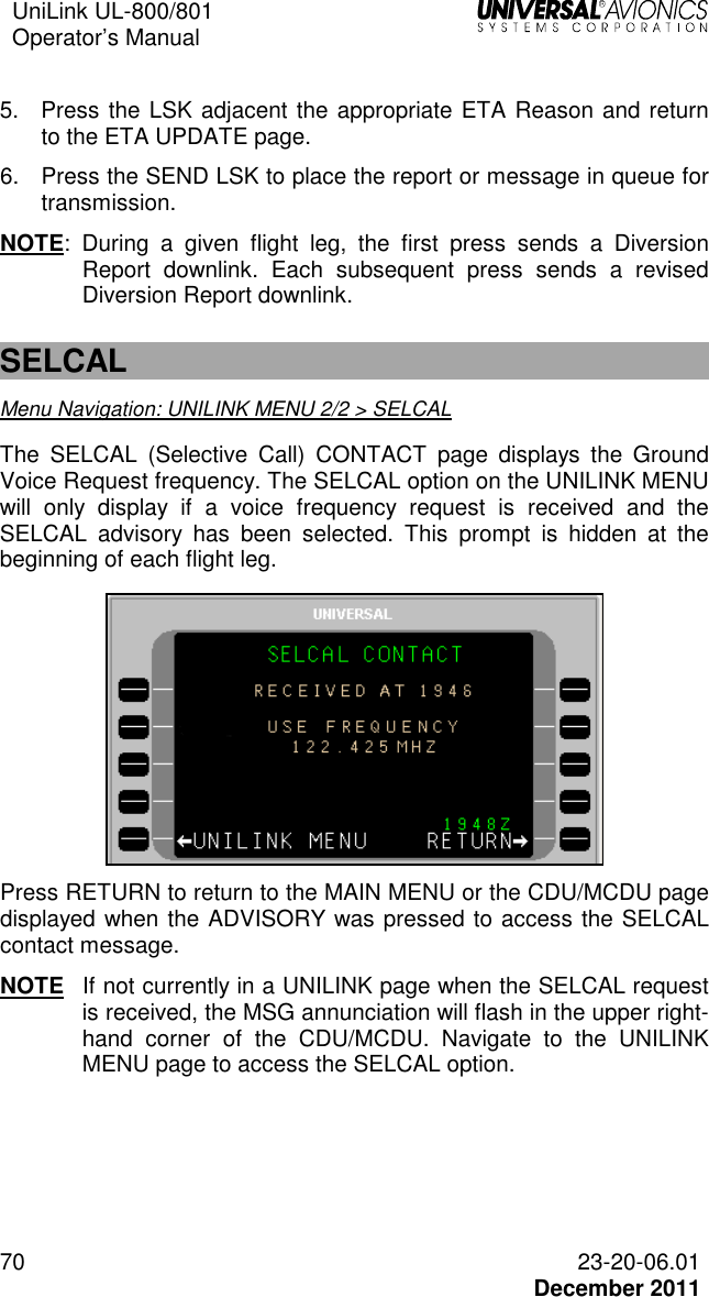
![UniLink UL-800/801 Operator’s Manual 23-20-06.01 69 December 2011 ETA UPDATE Menu Navigation: UNILINK MENU 2/2 > ETA UPDATE The ETA UPDATE page is used to send an ETA update message. To send an ETA Update message: 1. Press ETA UPDATE, LSK [3L] from UNILINK MENU page 2/2. The ETA UPDATE page will display. 2. With ETA active, enter an ETA and press [ENTER], or verify ETA data from the FMS. 3. If not active, press DEST, LSK [3L], enter a destination airport identifier, and press [ENTER]; or verify the default identifier from the FMS. NOTE: This field will display dashes if the destination airport is not available. The FMS ETE field is provided for reference only and displays the current computed FMS estimated time enroute. 4. Press REASON, LSK [1R] to access the ETA REASON page.](https://usermanual.wiki/Universal-Avionics-Systems/10801.Users-Manual-1/User-Guide-1641686-Page-79.png)
![UniLink UL-800/801 Operator’s Manual 23-20-06.01 71 December 2011 SITUATION Menu Navigation: UNILINK MENU 2/2 > SITUATION The SITUATION page permits the sending of emergency report messages for mechanical and medical emergencies. All situation reports include FUEL ONBD and ENDURANCE data from FMS FUEL page 2/5. To make the report: 1. Press SITUATION, LSK [2R] on UNILINK MENU page 2/2. The SITUATION page will display. 2. With SOULS active, enter the number of persons onboard and press [ENTER]. 3. If not active, press REMARKS, LSK [2L] (optional) and, enter information as needed. Up to 24 characters may be entered. 4. Press REASON, LSK [1R] to access the SITUATION REASON page.](https://usermanual.wiki/Universal-Avionics-Systems/10801.Users-Manual-1/User-Guide-1641686-Page-81.png)
![UniLink UL-800/801 Operator’s Manual 72 23-20-06.01 December 2011 5. Press the LSK adjacent the appropriate reason and return to the SITUATION page. If no selection is made, the REASON field will default to NONE. 6. Press the SEND LSK to place the report in queue for transmission. POS REPORT Menu Navigation: UNILINK MENU 2/2 > POS REPORT The POS REPORT page is used to modify Position Report data prior to sending, and to enable and disable the Auto Position report (AUTO) function. Data on this page is prefilled FMS/ADC data. Normally this data will be valid for the Position Report; however, temporary manual entries are possible for the current manually initiated transmission only. To make the report: 1. Press POS REPORT, LSK [3R] from UNILINK MENU page 2/2. The POS REPORT page will display. 2. With TO WPT active, enter a waypoint name and press [ENTER]. 3. The TO WPT ETA (LSK [2L]) is supplied by the FMS. To change, if not active, press and enter up to four digits (Time is UTC time). Press [ENTER]. 4. If not active, press GROUNDSPEED, LSK [3L] and enter up to three digits. Press [ENTER]. 5. If not active, press WINDS, LSK [4L] and enter three digits for wind direction. Press [ENTER] to advance the cursor to the velocity field and enter up to three digits. Press [ENTER].](https://usermanual.wiki/Universal-Avionics-Systems/10801.Users-Manual-1/User-Guide-1641686-Page-82.png)
![UniLink UL-800/801 Operator’s Manual 23-20-06.01 73 December 2011 6. If not already active, press ALTITUDE, LSK [3R] and enter current altitude if no ADC Altitude is available. Press [ENTER]. 7. Press the SEND LSK to place the report in queue for transmission. Automatic Position Reporting 1. Press AUTO, LSK [1R] to toggle the Automatic Report function to ENABLED or DISABLED. The current status is displayed to the left of AUTO. 2. If AUTO is set to ENABLED, press IN AIR INTV, LSK [2R] to set the report interval time (default is based on configuration setting). Press [ENTER]. NOTE: The IN AIR INTV option is not present if AUTO is set to DISABLED.](https://usermanual.wiki/Universal-Avionics-Systems/10801.Users-Manual-1/User-Guide-1641686-Page-83.png)
![UniLink UL-800/801 Operator’s Manual 74 23-20-06.01 December 2011 Maintenance Menu Navigation: UNILINK MENU 2/2 > MAINTENANCE Maintenance pages are used to access UniLink maintenance related functions. No operation-related functions are performed on this page or subpages. Operational tests can be conducted via the TESTS option. From the UniLink Menu 2/2, press MAINTENANCE, LSK [4L]. The MAINTENANCE 1/3 page will display. NOTE: See the associated UniLink Installation Manual for installation and maintenance procedures . Tests Menu Navigation: UNILINK MENU 2/2 > MAINTENANCE > TESTS There are several tests available to exercise the functionality of UniLink. They include PRINTER Test, IMAGE Test, UniLink SELF-TEST, PTT, FANS ALERTS, and UPLINK test. Press TESTS, LSK [2R] on the MAINTENANCE page to display the TESTS page.](https://usermanual.wiki/Universal-Avionics-Systems/10801.Users-Manual-1/User-Guide-1641686-Page-84.png)
![UniLink UL-800/801 Operator’s Manual 23-20-06.01 75 December 2011 Printer Test Menu Navigation: UNILINK MENU (2/2) > MAINTENANCE > TESTS > PRINTER If a printer is connected and configured, selection of PRINTER, LSK [1L] will send test message text to the printer. If there is no printer configured, the PRINTER option will not be displayed. When PRINTER is selected, a pop-up window PRINTER TEST IN PROGRESS” is displayed. When complete, the pop-up window is no longer displayed. The following will be printed: THIS IS NOT AN UPLINK. THIS IS AN INTERNALLY GENERATED PRINTER TEST MESSAGE. !"#$%&'()*+,-./0123456789:;<=>?@ABCDEFGHIJKLMNOPQRSTUVWXYZ[\]^_`{|}~; Image Test Menu Navigation: UNILINK MENU 2/2 > MAINTENANCE > TESTS > IMAGE Selection of IMAGE, LSK [2L] is used to display a test image. While the test image is being displayed, any key push will cause the display to return to the MAINTENANCE page. Image Test is not available when the aircraft is in the air. When IMAGE is selected, a pop-up window with the message IMAGE TEST IN PROGRESS will display. When the test is complete, an ADVISORY will display on the CDU and NEW WX MAP is displayed adjacent LSK [5L] (LSK for MCDU may be different). Press NEW WX MAP, LSK [5L] to display the generated test weather image. A test weather map will display with the title IMAGE BUS TEST.](https://usermanual.wiki/Universal-Avionics-Systems/10801.Users-Manual-1/User-Guide-1641686-Page-85.png)
![UniLink UL-800/801 Operator’s Manual 76 23-20-06.01 December 2011 NOTE: This image will display on an EFI-890R or MFD if installed and configured. To exit the image, press RTN, LSK [5R].The display returns to the TESTS page (NEW WX MAP and ADVISORY are no longer displayed). UniLink Self-Test Menu Navigation: UNILINK MENU(2/2 > MAINTENANCE > TESTS > SELF-TEST Selection of SELF-TEST, LSK [3L] places the system in a power up test mode. When the test is selected a pop-up window requesting to CONFIRM or CANCEL the test is displayed. Selecting CANCEL closes the pop-up window and returns to the current display. Selecting CONFIRM reboots UniLink. The message UNILINK/FMS COMM ERROR RESELECT UNILINK is displayed. During the period of reboot, the UNILINK displayed on the CDUMCDU is not selectable. When the test is complete, UNILINK will be selectable. Selecting UNILINK will display UNILINK MENU page 1/2. PTT (Push-To-Talk) (UL-801 only) Menu Navigation: UNILINK MENU 2/2 > MAINTENANCE. > TESTS > PTT If available, this test commands the radio to transmit for 3 seconds. A pop-up window PTT TEST IN PROGRESS will display for 3 seconds.](https://usermanual.wiki/Universal-Avionics-Systems/10801.Users-Manual-1/User-Guide-1641686-Page-86.png)
![UniLink UL-800/801 Operator’s Manual 23-20-06.01 77 December 2011 FANS ALERTS Menu Navigation: UNILINK MENU 2/2 > MAINTENANCE > TESTS > FANS ALERTS 1. Press FANS ALERTS, LSK [1R]. A pop-up window FANS DISCRETES NOT CONFIGURED will display, then close. Uplink Test Menu Navigation: UNILINK MENU 2/2 > MAINTENANCE > TESTS > UPLINK Selection of UPLINK, LSK [4R] causes a test uplink to be placed in the OPS message log, generating a NEW MSG advisory at the bottom of the display. 1. Press NEW MSG, LSK [5L] to display message. 2. If desired press PRINT, LSK [4R] to print the screen (Printer must be configured). 3. Press DELETE, LSK [4L] to delete test message. The display will return to the TESTS page.](https://usermanual.wiki/Universal-Avionics-Systems/10801.Users-Manual-1/User-Guide-1641686-Page-87.png)