Universal Avionics Systems 10801 Avionics Communication Management Unit User Manual 1
Universal Avionics Systems Corporation Avionics Communication Management Unit Users Manual 1
Contents
- 1. Users Manual 1
- 2. Users Manual 3
- 3. Users Manual 4
- 4. Users Manual 5
- 5. Users Manual 6
Users Manual 1
23-20-06.01 December 2011
UNILINK UL-800/801
OPERATOR’S MANUAL
(FANS Disabled)
SCN 30.X
With Corporate Database
The information contained herein is subject to the Export
Administration Regulations (“EAR”), 15 C.F.R. Parts 730-774.
Diversion contrary to U.S. law is prohibited.
This document is available at www.uasc.com
© 2011 UNIVERSAL AVIONICS SYSTEMS CORPORATION

UniLink UL-800/801
Operator’s Manual
23-20-06.01 ROR-1
December 2011
RECORD OF REVISIONS
Rev No. Issue Date Insertion Date Initials
Retain this record in front of the manual. Upon receipt of revision,
insert and remove pages according to the List of Effective Pages.
Then enter on this page the revision number, issue date, insertion
date and your initials.

UniLink UL-800/801
Operator’s Manual
23-20-06.01 ROTC-1
December 2011
RECORD OF TEMPORARY CHANGES
Change
No. Issue Date/
Page Insertion Date &
Initials Removal Date /
Initials / Reason

UniLink UL-800/801
Operator’s Manual
23-20-06.01 LOEP-1
December 2011
LIST OF EFFECTIVE PAGES
Original……..XX October 2010
Page No. Date
Page No. Date
Cover .............................. xx/xx/11
21 .................................... xx/xx11
22 .................................... xx/xx11
ROR-1 ............................. xx/xx11
25 .................................... xx/xx11
26 .................................... xx/xx11
ROTC-1 ........................... xx/xx11
23 .................................... xx/xx11
24 .................................... xx/xx11
LOEP-1............................ xx/xx11
25 .................................... xx/xx11
LOEP-2............................ xx/xx11
26 .................................... xx/xx11
27 .................................... xx/xx11
TOC-1 ............................. xx/xx11
28 .................................... xx/xx11
TOC-2 ............................. xx/xx11
29 .................................... xx/xx11
30 .................................... xx/xx11
1 ...................................... xx/xx11
31 .................................... xx/xx11
2 ...................................... xx/xx11
32 .................................... xx/xx11
3 ..................................... xx/xx11
33 .................................... xx/xx11
4 ...................................... xx/xx11
34 .................................... xx/xx11
5 ...................................... xx/xx11
35 .................................... xx/xx11
6 ...................................... xx/xx11
36 .................................... xx/xx11
7 ...................................... xx/xx11
37 .................................... xx/xx11
8 ...................................... xx/xx11
38 .................................... xx/xx11
9 ...................................... xx/xx11
39 .................................... xx/xx11
10 .................................... xx/xx11
40 .................................... xx/xx11
11 .................................... xx/xx11
41 .................................... xx/xx11
12 .................................... xx/xx11
42 .................................... xx/xx11
13 .................................... xx/xx11
43 .................................... xx/xx11
14 .................................... xx/xx11
44 .................................... xx/xx11
15 .................................... xx/xx11
45 .................................... xx/xx11
16 .................................... xx/xx11
46 .................................... xx/xx11
17 .................................... xx/xx11
47 .................................... xx/xx11
18 .................................... xx/xx11
48 .................................... xx/xx11
19 .................................... xx/xx11
49 .................................... xx/xx11
20 .................................... xx/xx11
50 .................................... xx/xx11

UniLink UL-800/801
Operator’s Manual
LOEP-2 23-20-06.01
December 2011
Page No. Date
Page No. Date
51 .................................... xx/xx11
86 .................................... xx/xx11
52 .................................... xx/xx11
53 .................................... xx/xx11
54 .................................... xx/xx11
55 .................................... xx/xx11
56 ................................... xx/xx11
57 .................................... xx/xx11
58 .................................... xx/xx11
59 .................................... xx/xx11
60 .................................... xx/xx11
61 .................................... xx/xx11
62 ................................... xx/xx11
63 .................................... xx/xx11
64 .................................... xx/xx11
65 .................................... xx/xx11
66 .................................... xx/xx11
67 .................................... xx/xx11
68 .................................... xx/xx11
69 .................................... xx/xx11
70 .................................... xx/xx11
71 .................................... xx/xx11
72 .................................... xx/xx11
73 .................................... xx/xx11
74 .................................... xx/xx11
75 .................................... xx/xx11
76 .................................... xx/xx11
77 .................................... xx/xx11
78 .................................... xx/xx11
79 .................................... xx/xx11
80 .................................... xx/xx11
81 .................................... xx/xx11
82 .................................... xx/xx11
83 .................................... xx/xx11
84 .................................... xx/xx11
85 .................................... xx/xx11

UniLink UL-800/801
Operator’s Manual
23-20-06.01 TOC-1
December 2011
TABLE OF CONTENTS
INTRODUCTION.................................................................................. 1
Components ..................................................................................... 1
Capabilities ....................................................................................... 1
Operations ........................................................................................ 2
FMS Input ..................................................................................... 2
Current Time ................................................................................. 2
SEND ............................................................................................ 3
Error Messages ............................................................................. 7
User Interface Menu Tree................................................................. 9
UniLink Menu 1/2 ........................................................................ 10
UniLink Menu 1/2 (continued) ..................................................... 11
UniLink Menu 2/2 ........................................................................ 12
Maintenance Menu ..................................................................... 12
Configuration Menu ..................................................................... 14
UNILINK MENU.................................................................................. 15
Flight Information ............................................................................ 16
ATIS Request .............................................................................. 17
TWIP Request ............................................................................ 18
Departure Clearance Request .................................................... 19
Oceanic Clearance Request ....................................................... 20
Verify Message Log .................................................................... 21
Pushback Clearance Request .................................................... 22
Expected Taxi Clearance Request ............................................. 23
Remarks – Create and Include with Requests ........................... 24
FREE-TEXT – Create and Send a Message .................................. 26
Create and Send a Message ...................................................... 26
Send a Message to another Aircraft ........................................... 27
Send an E-Mail............................................................................ 28
Send a Fax .................................................................................. 29
OOOI .............................................................................................. 30
OOOI Operation .......................................................................... 30
OOOI Current .............................................................................. 32
OOOI History .............................................................................. 33
COMM STATUS ............................................................................. 34
COMM CONTROL ...................................................................... 38
Text Weather Report Requests ...................................................... 45
Weather Map Requests .................................................................. 47
US Composite Radar .................................................................. 47
US Radar Tops and Movement .................................................. 48
IR Satellite ................................................................................... 50
Icing/Turbulence Potential .......................................................... 51
IFR/MVFR ................................................................................... 53
Significant Weather ..................................................................... 54

UniLink UL-800/801
Operator’s Manual
TOC-2 23-20-06.01
December 2011
Winds Aloft .................................................................................. 55
Weather Map Log ............................................................................ 57
Message Logs (SCN 30.X) .............................................................. 59
Verified Messages (SCN 30.X) .................................................... 60
Operations Messages (SCN 30.X) .............................................. 62
Weather Map Logs ...................................................................... 63
View Message - Detailed Message Screen ................................. 64
Delete or Print a Message ........................................................... 65
DELAY ............................................................................................. 66
DIVERSION ..................................................................................... 67
ETA UPDATE .................................................................................. 69
SELCAL ........................................................................................... 70
SITUATION ..................................................................................... 71
POS REPORT ................................................................................. 72
Maintenance .................................................................................... 74
Tests ............................................................................................ 74
GLOSSARY ........................................................................................ 79
INDEX ................................................................................................. 85

UniLink UL-800/801
Operator’s Manual
23-20-06.01
1
December 2011
INTRODUCTION
UniLink is an air-to-ground digital data communication system that
operates with Universal Avionics Systems Corporation’s (UASC’s)
Fight Management Systems (FMSs). It is capable of using a variety of
media such as Satellite Communications (SatCom) and Very High
Frequency (VHF) communications to exchange data with Datalink
Service Providers (DSPs). When communicating over the Aircraft
Communications Addressing and Reporting System (ACARS)
network, UniLink is the functional equivalent of an ARINC 758
Communications Management Unit (CMU). The UL-801 contains an
imbedded VHF data radio (VDR) whereas the UL-800 requires an
external VDR. The VDR provides ACARS and various other types of
network communications capability for UniLink.
The UniLink UL-80X database-driven user interface and message set
is easily customized to match airline operational requirements
uploaded into the UL-80X without affecting product software or
certification status.
NOTE: The current UniLink 80X uses Software Control Number (SCN)
30.X. It is important to ensure that operating documentation
reflects the SCN being used.
NOTE: The colors shown on the screens in this operator’s manual are
based on an FMS with SCN 1000.5/1100.5 installed and
configured for STANDARD-2 color pallet.
Components
A VHF receiver transmitter or ARINC 741 SatCom is required for full
ACARS communications. An airborne telephone system is required to
obtain weather graphics and is capable of providing limited ACARS
communication with some service providers.
Capabilities
The two-way data link allows the crew to request and receive
clearances, weather reports, and messages. Weather graphics are
available on UASC’s FMS using flat panel displays and air phone
equipment. UniLink advisories alert the crew to newly received
messages.

UniLink UL-800/801
Operator’s Manual
2
23-20-06.01
December 2011
Operations
Crew interface is accomplished through the FMS CDU and/or MCDU,
utilizing a UASC FMS with SCN 1000.5/1100.5 or later. Data may be
entered at any field highlighted by a cursor. The cursor is displayed in
the first empty data field. Fields with plus signs (+) indicate information
is required. Fields exhibiting minus signs (-) indicate input is optional.
If there is no cursor displayed in a data field, selecting the ENTER key
will place the cursor over the first enterable field on the page. Data is
then entered into the field using the CDU/MCDU alphanumeric keys.
In some situations, flight progress and related data from the FMS will
be prefilled. Subsequent presses of the [ENTER] key will move the
cursor to the next enterable field. Pressing a line select key (LSK)
highlights the corresponding data entry field. Selecting [ENTER] when
the cursor is in the last data field on the page results in the cursor
parking off of the page. Pressing [ENTER] again positions the cursor
on the initial enterable field on the page.
FMS Input
The FMS continuously provides current data to UniLink. Many
messages and requests have fields that prefill with FMS flight progress
data and computed information. In most cases the user accepts the
data for inclusion into the message. It is possible however to change a
value by overriding that value with a manual data entry. Manual entries
are generally retained until power shutdown, although data that would
normally change as a flight progresses will be cleared once the page
has been exited (is no longer displayed).
Source FMS
The crew must ensure that the FMS that is navigating the aircraft
(Source FMS) is the same FMS that supplies data to UniLink. The
Source FMS is shown on the SOURCE FMS page, accessed via
MAINTENANCE (1/3) > SENSOR STATUS > SOURCE FMS.
SOURCE FMS
selection
method selected fms
Îmanual {*}FMS1®
FMS2®
¡¢z
¬UNILINK RETURN®
UniLink UL-800/801
Operator’s Manual
23-20-06.01
3
December 2011
The Source FMS is indicated by an asterisk next to it. Any available
FMS can be manually selected by pressing the adjacent LSK. If
automatic (AUTO) selection is desired, the SELECTION METHOD
LSK will toggle between MANUAL and AUTO.
NOTE: It is important for the crew to ensure that the Source FMS is
not changed prior to an expected flight plan modification uplink.
If the Source FMS is changed prior to the uplink, the flight plan
information will need to be transferred to the new Source FMS
from the previously designated FMS.
Communications
Prior to entering Oceanic Airspace (and loss of VHF communications)
the crew should suspend VHF and transition to satellite
communication (See STATE under VHF DATA in the COMM
CONTROL section). The crew must enable VHF communications
once again when reentering a VHF-available region.
Current Time
On every UniLink screen above the RETURN option at LSK [5R], the
current UTC time is displayed.
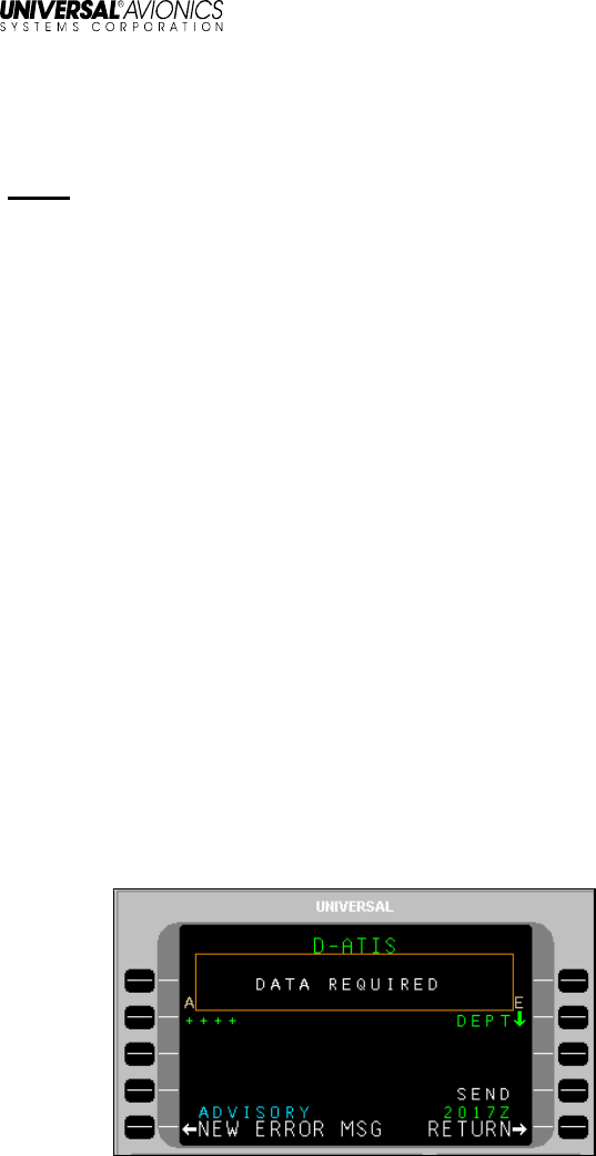
SEND
When the SEND LSK is pressed, the request is placed into queue for
transmission. The delivery status of the message appears above the
SEND option. If data required for the message has not been entered
completely, the SEND option will display as inactive and if selected, a
pop-up window DATA REQUIRED will display (indicating the data is
insufficient).The SEND prompt will not display an arrow (indicating
active) until all required data is entered. Clear the pop-up window by
pressing any key or LSK.

UniLink UL-800/801
Operator’s Manual
4
23-20-06.01
December 2011
SEND status displays the current status of the message. When the
SEND LSK is pressed, the status will briefly change to QUEUED, then
SENDING. The selected media for transmission (VHF, SAT, or TEL) is
indicated after SENDING. When acknowledgement is received from
the DSP, SENT status will display.

UniLink UL-800/801
Operator’s Manual
23-20-06.01
5
December 2011
UniLink Advisories
The bottom left LSK on each UniLink page will display either the
UNILINK MENU prompt or UniLink advisories. UniLink advisories
notify the crew of UniLink activity that may require user action. Only
one advisory will display at a time in the order of priority. Pressing the
adjacent LSK allows viewing of the advisory message.
When no advisory is displayed, the advisory field is used to display the
UNILINK MENU prompt. Selecting this prompt displays the UNILINK
MENU.
When on an FMS page, UniLink advisories will be indicated by the
flashing MSG annunciator. Pressing the [MSG] key will allow viewing
of UniLink advisories and messages via the NEW MESSAGE Advisory
prompt (LSK [5L]). This will open the appropriate UniLink page.
Advisory Messages
NEW ERROR MSG – This advisory is active when an unviewed entry
exists in the Error Log. Selection of this advisory displays the detailed
error message page for most recently logged error message that has
not been viewed.
ACKNOWLEDGE – Indicates that an uplink message that is displayed
requires crew acknowledgment. Selection will send an
acknowledgment message.
NEW MSG – Indicates a new unverified message in the Uplink Log.
Selection of this advisory displays the detailed message page for the
latest unread unverified message.
NEW VERIF MSG – Indicates a new verified message in the Uplink
Log. Selection of this advisory displays the detailed message page for
the latest unread verified message.
NEW WX MAP – Indicates a new unviewed weather graphic in the
Graphic Log. Selection of this advisory displays the most recent
graphic.
SELCAL – Indicates a SELCAL request has been received. Selection
of this advisory displays the SELCAL page.
VHF VOICE (applies to UL-800 only) – Indicates the VDR is in Voice
Mode. Selection of this advisory displays the VHF VOICE page.
TEL SUSPEND – Indicates the configured dial attempt limit has been
reached and TEL LINK has been suspended (or TEL LINK has been
manually suspended). Selection of this advisory displays the TEL
DATA page.

UniLink UL-800/801
Operator’s Manual
6
23-20-06.01
December 2011
GND DELAY – Indicates a configurable timer has elapsed since the
last OUT event (push back) and the OFF event (take off) has not yet
occurred. Selection of this advisory displays the EST TIME OFF page.
NOCOMM – Indicates multiple air/ground links are not available.
Selection of this advisory displays the COMM STATUS page.
SAT NOCOMM – Indicates the configured SatCom air/ground link is
not available. Selection of this advisory displays the COMM STATUS
page.
TEL NOCOMM – Indicates the configured airborne telephony
(SatCom) system link is not available. Selection of this advisory
displays the COMM STATUS page.
VHF NOCOMM – Indicates UniLink has determined that a VHF
air/ground link is not available. Selection of this advisory displays the
COMM STATUS page.
UniLink UL-800/801
Operator’s Manual
23-20-06.01
7
December 2011
Error Messages
Most error messages generate a NEW ERROR MSG advisory which
is displayed in the ERROR LOG pages. Certain error messages which
are considered more urgent are displayed in a pop-up window in the
middle of the current UniLink page. Examples include: QUEUE FULL,
DISPLAY PROCESSOR FAIL and A740: PRINTER FAIL.
Entry Error Pop-up Windows
UniLink provides feedback when an invalid entry is made. After an
invalid entry, a pop-up window identifies the entry error.
The following is a list of data entry errors and the condition that will
initiate the error pop-up window.
Screen Text Condition
VALUE TOO LARGE The entered numeric value
exceeds the allowable maximum.
VALUE TOO SMALL The entered numeric value is less
than the allowable minimum.
TOO MANY CHARACTERS The entered number of characters
exceeds the allowable maximum.
TOO FEW CHARACTERS The entered number of characters
is less than the allowable
minimum.
VALUE MUST BE NUMERIC The prompt only accepts digits.
VALUE MUST BE
ALPHABETIC The prompt only accepts letters.
TOO MUCH PRECISION The entered numeric value has
too many numbers to the right of
the decimal point.

UniLink UL-800/801
Operator’s Manual
8
23-20-06.01
December 2011
Screen Text Condition
NEGATIVE NOT PERMITTED The prompt only accepts positive
numbers.
MISSING N OR S The entered latitude does not
specify a hemisphere.
MISSING E OR W The entered longitude does not
specify a hemisphere.
INVALID NUMBER The entered characters could not
be interpreted as a number.
INVALID ENTRY The entered characters do not
conform to specific textual data
item input restrictions.
ILLEGAL HYPHEN The entered tail number begins or
ends with a hyphen.
ILLEGAL VHF FREQUENCY The entered frequency is not a
valid VHF voice or data
frequency, or is the CSC
frequency (136.975).
ILLEGAL DATA FREQUENCY The Emergency Voice frequency
(121.500) has been entered at a
prompt that expects to receive a
data frequency.
PRESSURE OUT OF RANGE The entered atmospheric
pressure is out of range.
INVALID SECONDS VALUE The entered seconds value within
a time field is invalid.
INVALID MINUTES VALUE The entered minutes value within
a time field is invalid.
INVALID HOURS VALUE The entered hours value within a
time field is invalid.
INVALID DAY The entered day value within a
date field is invalid.
INVALID MONTH The entered month value within a
date field is invalid.
INVALID YEAR The entered year value within a
date field is invalid.
INVALID LEAP YEAR The entered date value includes
Feb 29
th
in a year that is not a
leap year.

UniLink UL-800/801
Operator’s Manual
23-20-06.01
9
December 2011
Screen Text Condition
INVALID SECONDS The entered seconds value within
a latitude or longitude field is
invalid.
INVALID MINUTES The entered minutes value within
a latitude or longitude field is
invalid.
DATA REQUIRED An attempt has been made to
navigate to a new page or send a
request without supplying required
information.
Alerting
Message Alerting
Message alerting functions include visual and aural alerts, and digital
outputs to various Line-Replaceable Units (LRU). The outputs are
intended to drive visual or aural alerting when a new uplink message is
received. The digital outputs provide messaging alerts that may be
used by other devices for additional alerting functions, such as the
FMS MSG annunciator.
Alert Inhibiting
UniLink Alert Inhibiting operates in order to suspend the output of
message alerting during critical phases of flight (i.e., takeoff and
landing). Displayed UniLink advisories are not suppressed during
critical flight phases.
NOTE: If UniLink transitions out of the takeoff phase due to
transitioning directly into the landing phase, UniLink will
continuously inhibit alert outputs. This ensures there are no
aural alerts that could potentially distract the crew.
UniLink UL-800/801
Operator’s Manual
10
23-20-06.01
December 2011
User Interface Menu Tree
The UniLink Main Menu page is accessed from the UNILINK prompt
on either DATA 1/4 or the MESSAGE page (from a reboot or initial
startup). To navigate down through the menu tree, select the
applicable page option LSKs to move to the desired function. Use the
RETURN LSK to move back up the menu tree.
Pages shown in the menu trees may or may not be available
depending on specific installation configuration. Check with installer for
specific configuration details.
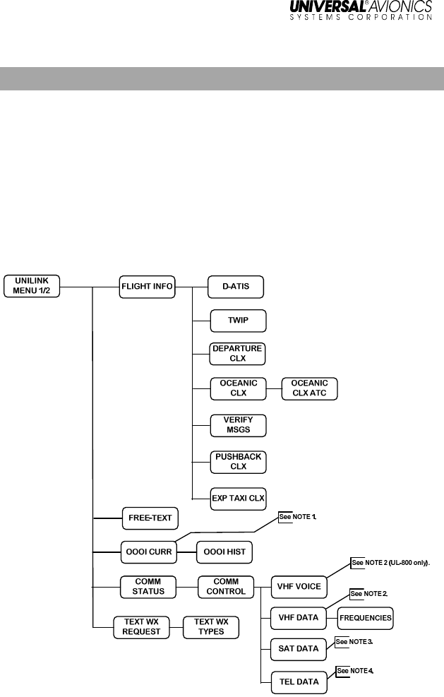
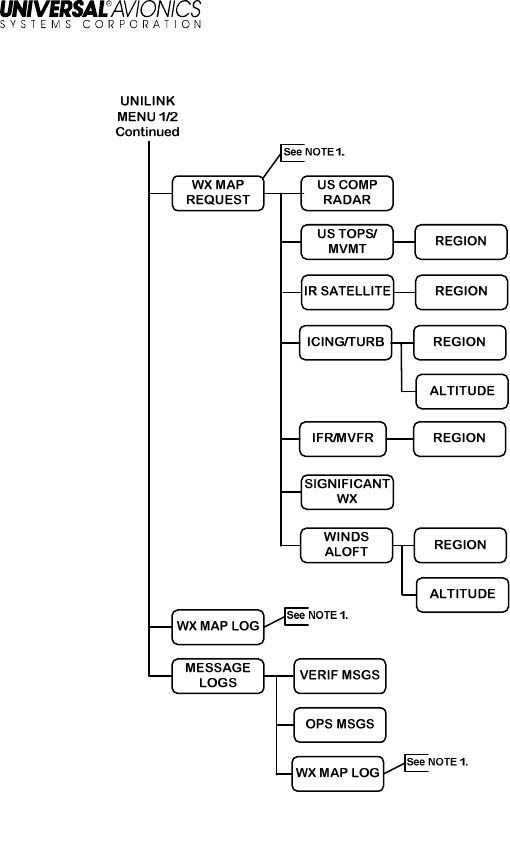
UniLink Menu 1/2
NOTES:
1. Only available if OOOI is enabled in configuration.
2. Only available if VHF is enabled in configuration.
3. Only available if DATA is enabled in configuration.
4. Only available if TEL is enabled in configuration.
(Continued on next page)
UniLink UL-800/801
Operator’s Manual
23-20-06.01
11
December 2011
UniLink Menu 1/2 (continued)
NOTES:
1. Only available if TEL is enabled in configuration.
(Continued on next page)
UniLink UL-800/801
Operator’s Manual
12
23-20-06.01
December 2011
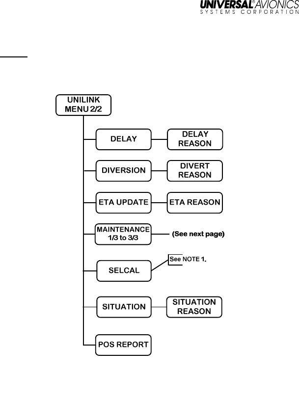
UniLink Menu 2/2
NOTE: The SELCAL option only displays when associated messages
are available and pending.
NOTES:
1. Check with DSP for availability of this feature.

UniLink UL-800/801
Operator’s Manual
23-20-06.01
13
December 2011
Maintenance Menu
Maintenance pages are used to access UniLink maintenance-related
functions. They are accessed by pressing the MAINTENANCE LSK on
the UNILINK MENU page 2/2. Other than TESTS, there are no user-
related functions that are performed on this page or subpages. See
the associated UniLink Installation Manual for installation and
maintenance procedures.

UniLink UL-800/801
Operator’s Manual
14
23-20-06.01
December 2011
Configuration Menu
Configuration pages are used to access UniLink configuration-related
functions. They are accessed by selecting the CONFIG LSK on the
MAINTENANCE 1/3 page. There are no user-related functions that
are performed on this page or subpages. See the associated UniLink
Installation Manual for installation and configuration procedures.
I/O CONFIG
GRAPHICS
DISC IN
DISC OUT
ARINC RX
ARINC TX
SERIAL
POS REPORT
VHF CONFIG
SAT CONFIG
PRIORITY
TEL CONFIG
REVIEW
AiRCRAFT
CLEARANCES
ALERTS
SYS CONFIG
2/4
SYS CONFIG
3/4
SYS CONFIG
4/4
MAINTENCE
1
/
3
(continued from
previous page)
SYS CONFIG
1/4
UniLink UL-800/801
Operator’s Manual
23-20-06.01
15
December 2011
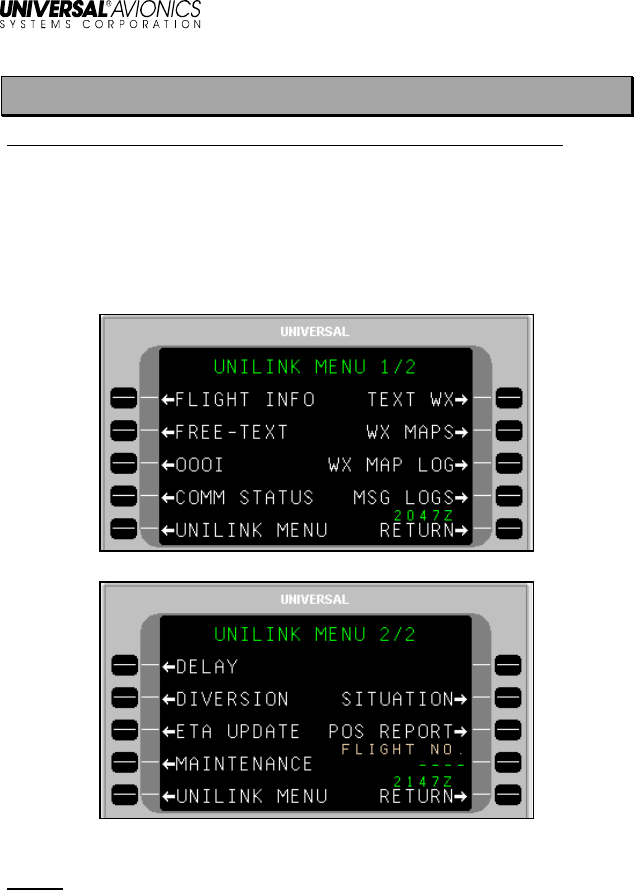
UNILINK MENU
Menu Navigation: DATA (1/4) or MESSAGE 1/1 >UNILINK MENU 1/2
The UniLink Menu pages are accessed by selecting UNILINK from
either DATA 1/4 page or the MESSAGE 1/X page. The DATA 1/4
page is accessed by pressing the [DATA] key. The MESSAGE 1/X
page is accessed by pressing the [MSG] key.
NOTE: Based on installation and configuration, the FLIGHT NO. field
may or may not be displayed.
UniLink UL-800/801
Operator’s Manual
16
23-20-06.01
December 2011
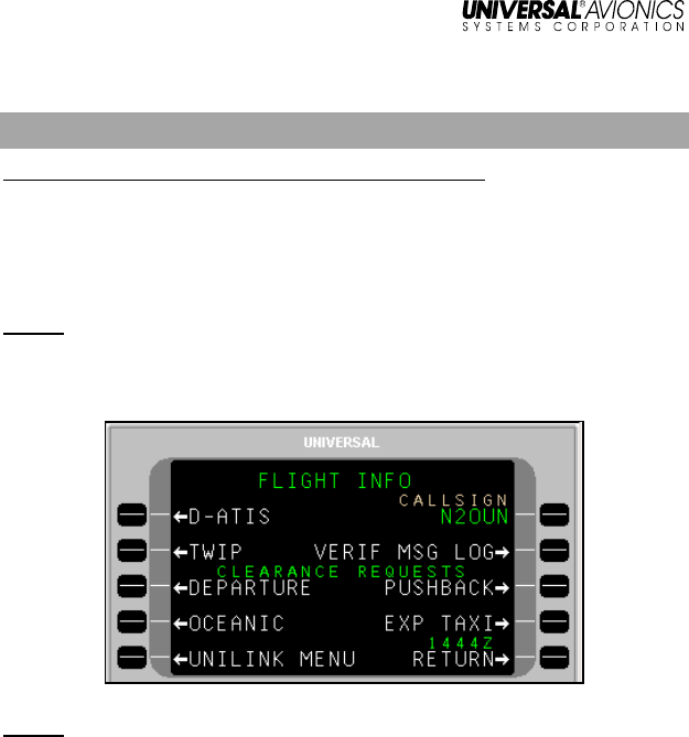
Flight Information
Menu Navigation: UNILINK MENU 1/2 > FLIGHT INFO
On the UNILINK MENU 1/2 Page, press FLIGHT INFO, LSK [1L], to
access the FLIGHT INFO page. All services provided on this menu
are available only over the ACARS VHF or SatCom packet data
network.
NOTE: Flight Information Services are advisory only. It is the
responsibility of the pilot to exercise reasonable and prudent
judgment in the use of these advisory services.
NOTE: DEPARTURE, OCEANIC, PUSHBACK, and EXP TAXI
requests are configurable options and are not displayed if
configured as disabled.
The aircraft tail number is automatically inserted in the CALL SIGN
field. If the aircraft has a different ATS call sign assigned for the flight,
it should be manually entered.
To manually enter a callsign:
1. Press LSK [1R]. The CALLSIGN field will become active.
2. Enter the desired callsign using the alphanumeric keys.
3. Press [ENTER]. The new callsign will display in the field.
UniLink UL-800/801
Operator’s Manual
23-20-06.01
17
December 2011
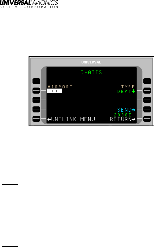
ATIS Request
Menu navigation: UNILINK MENU 1/2 > FLIGHT INFO > D-ATIS
The D-ATIS page is used to request local arrival or departure
Automatic Terminal Information Service (ATIS).
To request ATIS:
1. Press D-ATIS, LSK [1L] on the FLIGHT INFO page. The D-ATIS
page will display.
2. With AIRPORT active, enter the Airport Identifier and press
[ENTER], or accept the default destination airport from the FMS
flight plan.
NOTE: If an incomplete identifier is entered, the message TOO FEW
CHARACTERS will display and the field will flash. Pressing
the LSK and re-entering a complete identifier will correct the
error.
3. DEPT is the default type of ATIS. Press TYPE, LSK [2R] to toggle
the field between ARRV and DEPT as needed.
4. Press SEND, LSK [4R] to place the message in queue for
transmission.
NOTE: If the information on this page is incomplete, the pop-up
window DATA REQUIRED will display and the SEND prompt will not
enable.
UniLink UL-800/801
Operator’s Manual
18
23-20-06.01
December 2011
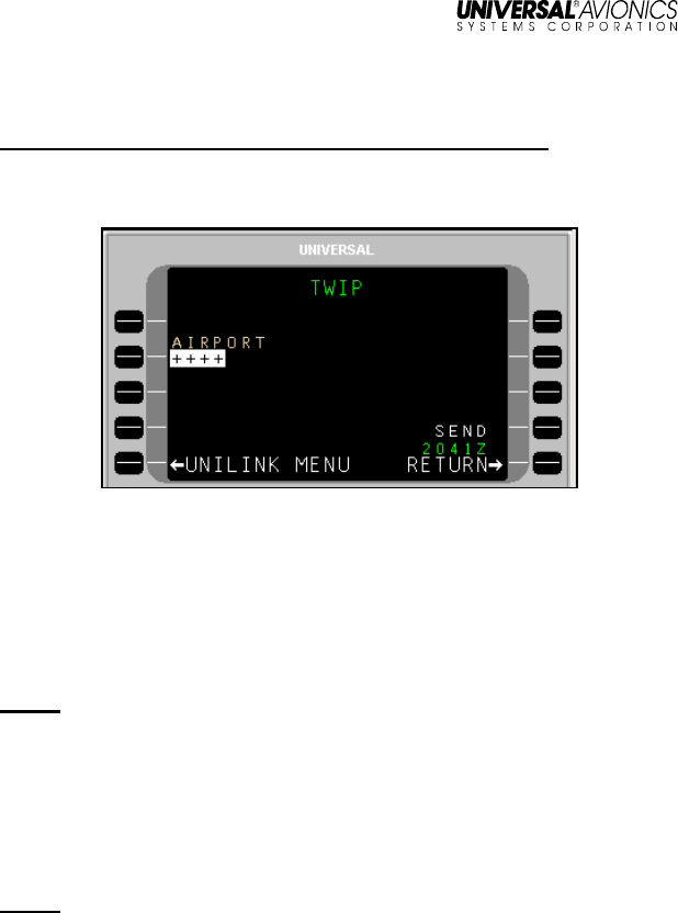
TWIP Request
Menu navigation: UNILINK MENU 1/2 > FLIGHT INFO > TWIP
The TWIP page is used to request Terminal Weather Information for
Pilots (TWIP).
To make a TWIP request:
1. Press TWIP, LSK [2L] on the FLIGHT INFO page. The TWIP
page will display.
2. With AIRPORT active, enter a destination airport and press
[ENTER] or accept the Destination Airport from the FMS flight
plan.
NOTE: If an incomplete identifier is entered, the message TOO FEW
CHARACTERS will display and the field will flash. Pressing
the LSK and re-entering a complete identifier will correct the
error.
3. Press the SEND LSK to place this message in queue for
transmission. The SEND prompt will not be enabled if the
information on this page is incomplete.
NOTE: If the information on this page is incomplete, the pop-up
window DATA REQUIRED will display and the SEND prompt
will not enable.
UniLink UL-800/801
Operator’s Manual
23-20-06.01
19
December 2011
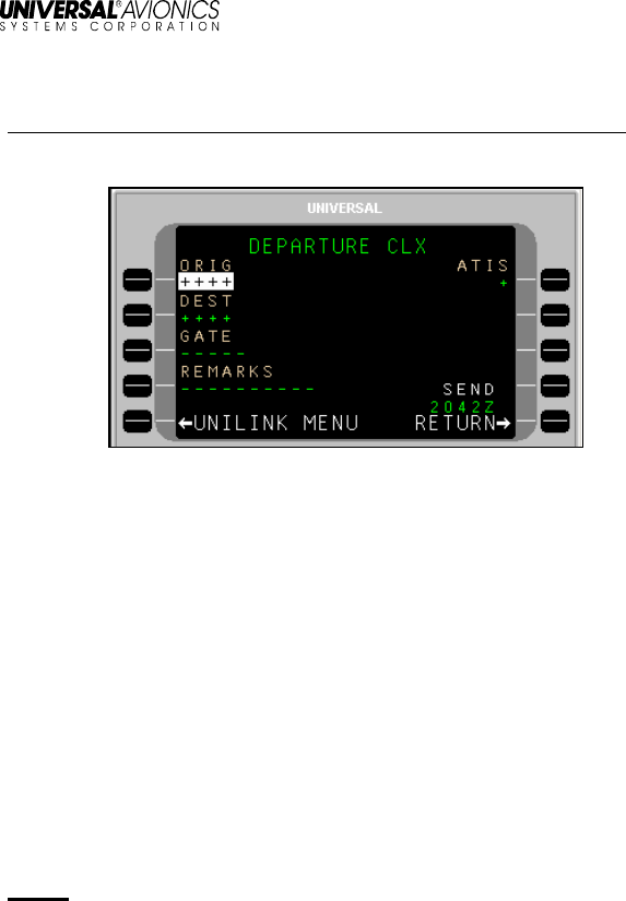
Departure Clearance Request
Menu navigation: UNILINK MENU 1/2 > FLIGHT INFO > DEPARTURE
The DEPARTURE CLX page is used to request departure clearance.
To request a Departure Clearance:
1. Press DEPARTURE, LSK [3L] on the FLIGHT INFO page. The
DEPARTURE CLX page will display.
2. Verify or change the ORIG (origination) airport. This field defaults
to the departure airport identifier from the FMS.
3. Verify or change the DEST (destination) airport. This field defaults
to the destination airport from the FMS.
4. Enter GATE number (optional).
5. Press the REMARKS LSK to enter any remarks as needed (see
the REMARKS Section in this manual).
6. Enter the latest ATIS version (alpha character).
7. Press SEND, LSK [4R] to place this message in queue for
transmission.
NOTE: The SEND prompt will not be enabled if the required
information on this page is incomplete, the call sign from the
Flight Information Services page is not entered, or the aircraft
type has not been configured from Aircraft Configuration
page. Any attempt to send this request with incomplete
information will result in the pop-up window DATA REQURED
displaying.
UniLink UL-800/801
Operator’s Manual
20
23-20-06.01
December 2011
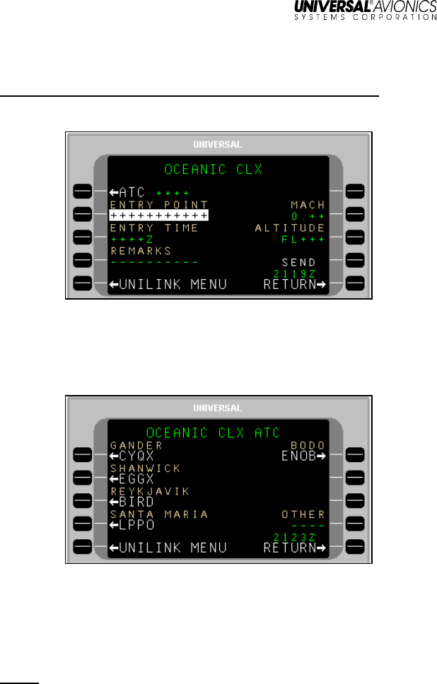
Oceanic Clearance Request
Menu navigation: UNILINK MENU 1/2 > FLIGHT INFO > OCEANIC
The OCEANIC CLX page is used to request Oceanic Clearance.
To request an Oceanic Clearance:
1. Press OCEANIC, LSK [4L] on the FLIGHT INFO page. The
OCEANIX CLX page will display.
2. Press ATC, LSK [1L] to open the OCEANIX CLX ATC page.
3. Select the ATC Station using the adjacent LSK, or enter a station
ID in the OTHER field, LSK [R4]. The OCEANIX CLX page will
display, showing the selected ATC station.
4. If not active, press ENTRY POINT, LSK [3L] and enter the point of
entry into oceanic airspace, then press [ENTER}.
NOTE: The Entry can have from 3 to 11 characters to specify the
position by latitude/longitude, or by waypoint identifier.
5. If not active, press ENTRY TIME, LSK [3L] and enter the
requested time for the clearance. Press [ENTER].

UniLink UL-800/801
Operator’s Manual
23-20-06.01
21
December 2011
6. If not active, press MACH, LSK [2R] and enter the requested
Mach number. Press [ENTER].
7. If not active, press ALTITUDE, LSK [3R] and enter the requested
flight level. Press [ENTER].
8. Press REMARKS, LSK [4L] and enter any remarks as needed.
OCEANIC Clearance remarks are entered using the OCEANIC
CLX REMARKS page (see the REMARKS Page section in this
manual).
9. Press SEND, LSK [4R] to place the message in queue for
transmission.
NOTE: If the information on this page is incomplete, a pop-up window
DATA REQUIRED will display and the SEND prompt will not
enable
Verify Message Log
Menu navigation: UNILINK MENU (1/2) > FLIGHT INFO > VERIF MSG LOG
The VERIF MSGS page displays all verified uplink and downlink
messages and can be used to check the queue status of sent
messages. See VERIF MSG LOG in the Message Logs section of this
manual.

UniLink UL-800/801
Operator’s Manual
22
23-20-06.01
December 2011
Pushback Clearance Request
Menu navigation: UNILINK MENU 1/2 > FLIGHT INFO > PUSHBACK
The PUSHBACK CLX page is used to request pushback clearance.
To request Pushback Clearance:
1. Press PUSHBACK, LSK [3R] on the FLIGHT INFO page. The
PUSHBACK CLX page will display.
2. Verify the ORIG (Origination) airport. Change by pressing ORIG,
LSK [1L] (if not active) and entering a different airport. Press
[ENTER].
3. If not active, press DEST (Destination), LSK [2L] to enter the
destination airport. Press [ENTER].
4. If not active, press GATE, LSK [3L] to enter gate Information
(optional). Press [ENTER].
5. If not active, press SCHED DATE, LSK [1R] to enter the
scheduled date (day). Press [ENTER].
NOTE: Default date is per GMT.
6. If not active, press SCHED TIME, LSK [2R] to enter the scheduled
time. Press [ENTER].
7. Press REMARKS, LSK [4L] to enter any remarks as needed
(optional). Pushback remarks are entered using the PUSHBACK
CLX REMARKS page (See the Remarks Page section in this
manual).
8. Press SEND, LSK [4R] to place this message in queue for
transmission.
UniLink UL-800/801
Operator’s Manual
23-20-06.01
23
December 2011
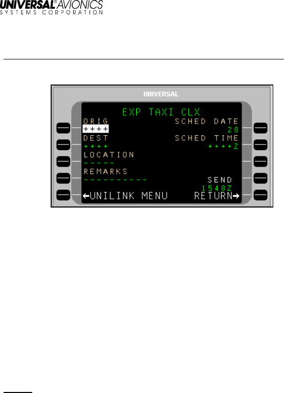
Expected Taxi Clearance Request
Menu navigation: UNILINK MENU (1/2) > FLIGHT INFO > EXP TAXI
The EXP TAXI CLX is used to request an Expected Taxi Clearance.
To request an Expected Taxi Clearance:
1. Press EXP TAXI, LSK [4R] on the FLIGHT INFO page. The EXP
TAXI CLX page will display.
2. Verify the ORIG (Origination) airport. Change by pressing ORIG,
LSK [1L] and entering a different airport. Press [ENTER].
3. If not active, press DEST (Destination), LSK [2L] to enter the
destination airport. Press [ENTER].
4. If not active, press GATE, LSK [3L] to enter gate Information
(optional). Press [ENTER].
5. If not active, press SCHED DATE, LSK [1R] to enter the
scheduled date (day). Press [ENTER].
NOTE: Default date is per GMT.
6. If not active, press SCHED TIME, LSK [2R] to enter the scheduled
time. Press [ENTER].
7. Press REMARKS, LSK [4L] to enter any remarks as needed
(optional). Taxi Clearance remarks are entered using the EXP
TAXI CLX REMARKS page (See the Remarks Page section in
this manual).
8. Press SEND, LSK [4R] to place this message in queue for
transmission.

UniLink UL-800/801
Operator’s Manual
24
23-20-06.01
December 2011
Remarks – Create and Include with Requests
Menu navigation: UNILINK MENU 1/2 > FLIGHT INFO > DEPARTURE or
OCEANIC or PUSHBACK or EXP TAXI
The Remarks page is available with the following Flight Information
(FLIGHT INFO) services pages:
• DEPARTURE
• OCEANIC
• PUSHBACK
• EXP TAXI
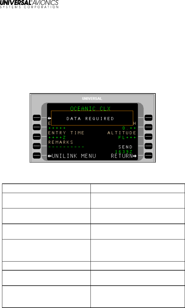
To access the REMARKS Page;
1. On a Flight Information service page (in this example, OCEANIC
CLX), press the REMARKS LSK.
The associated Remarks page will open with the cursor (@) flashing
on the text line.
NOTE: In this example, OCEANIC CLX is used. All REMARKS pages
are operated in the same manner.

UniLink UL-800/801
Operator’s Manual
23-20-06.01
25
December 2011
2. Create a message using the alphanumeric keys and LSKs.
• The [ + ] key inserts spaces in the text.
• LSKs [1L] through [3L] provide special characters as indicated
on the display. Pressing the specific LSK multiple times cycles
through the displayed choices. To enter a special character
several times in a row, select another key between special
character LSK presses (example: to enter several periods in a
row, press LSK [2L], then the right-arrow key (which does
nothing), then [2R], then the right-arrow key, etc.).
• The arrow LSKs ([1R] through [4R]) move the cursor position
within text already entered. Text entered at the cursor position
in front of other text is inserted and word wrapping will occur
as necessary.
• To start a new line of text, press [ENTER]; the cursor will start
a new line of text.
• The CLEAR LSK erases all entered text on the page.
• The text automatically word wraps to the next line.
• The number of pages in the message will increase as
necessary to accommodate entered text.
3. When finished editing the text portion of the message, press
RETURN, LSK [5R]. The entered text will display in the
REMARKS field for review.
NOTE: The REMARKS field displays the first 7 characters of entered
text. A following ellipsis (…) indicates there is more text in the
message. The REMARKS page allows review of the entire
remarks text.
4. Press the SEND LSK to place the message in queue for
transmission.
UniLink UL-800/801
Operator’s Manual
26
23-20-06.01
December 2011
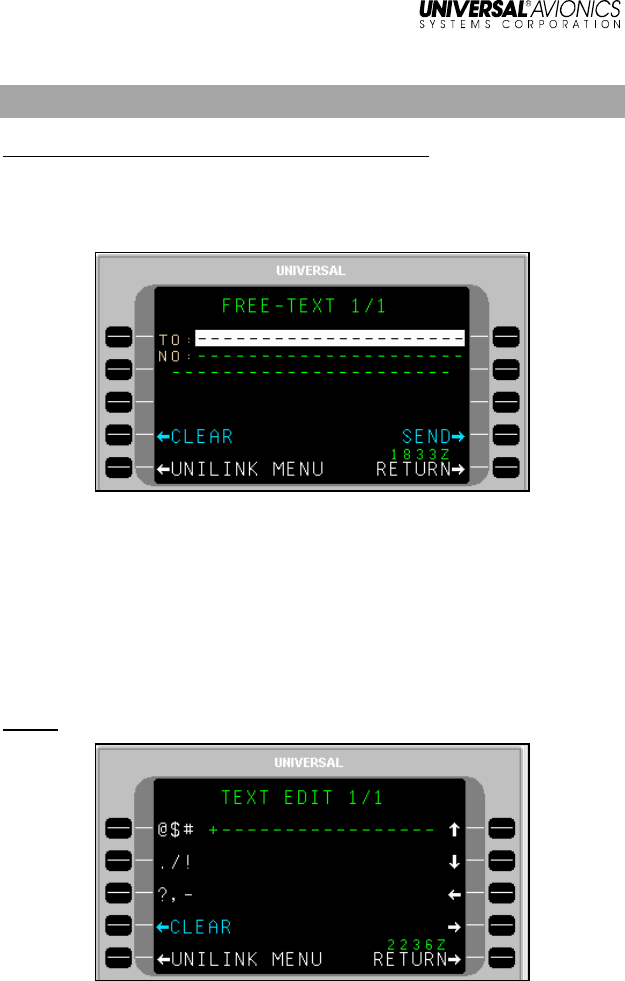
FREE-TEXT – Create and Send a Message
Menu navigation: UNILINK MENU 1/2 > FREE TEXT
The FREE-TEXT option is available at LSK [2L] on the UNILINK
MENU 1/2 page. The FREE TEXT page allows the user to create and
edit text messages.
Create and Send a Message
1. Press FREE-TEXT, LSK [2L] on the UNILINK MENU 1/2 page.
2. With the TO field active, enter the destination identifier. Press
[ENTER].
3. Enter the destination/recipient telephone number (if known) in the
NO: field and press [ENTER]. Pressing [ENTER] moves the
cursor to the first text line of the TEXT EDIT page.
NOTE: Pressing LSK [2L] will also bring up the TEXT EDIT page.

UniLink UL-800/801
Operator’s Manual
23-20-06.01
27
December 2011
4. Create a message using the alphanumeric text option keys.
• The [ ± ] key is used to insert a space.
• The text automatically word wraps to the next line.
• The number of pages in the message will increase as
necessary to accommodate entered text.
• The left LSKs are used to insert special characters as
indicated on the display. Selecting the same special
character key multiple times will cause the selected
character to cycle between the three displayed choices.
• The right line select keys are used to move the cursor (+)
position within the text that has been entered.
• Any text entered at the cursor position in front of other text
will be inserted and word wrapping will automatically occur
as necessary.
• To start a new line of text, press [ENTER] and the cursor (+)
will start a new line of text.
5. When finished editing the text portion of the message, press
RETURN, LSK [5R]. The entered text is displayed on the FREE
TEXT page for review with additional pages added as necessary.
6. Press SEND to place the message in queue for transmission.
QUEUED will display above the SEND option to indicate the
message is in queue.
Send a Message to another Aircraft
1. On the Free Text page, enter the destination registry in the TO
field and press [ENTER].
2. Enter the letter “A” in the first position of the NO field followed by
the registry of the destination aircraft and press [ENTER].
3. Enter the message text in the free text area. When finished
editing the text portion of the message, press RETURN, LSK [5R].
The entered text is displayed on the FREE TEXT page for review
with additional pages added as necessary.
4. Press SEND, LSK [4R] to place the message in queue for
transmission.

UniLink UL-800/801
Operator’s Manual
28
23-20-06.01
December 2011
Send an E-Mail
NOTE: Arrangement with DSP must be made for e-mail capability to
be available. Specific detailed instructions for email operation
may differ from the following procedure, depending on the
service provider.
1. With the TO line active, press [ENTER] to make the NO field
active.
2. Enter "E" in the first position of the NO field and press [ENTER].
3. In the free text area, enter the destination e-mail address. Use DA
for a dash (-), DOT for dot (.) and AT for at symbol (@). Delimit
the address with ST (Example: SCOTT AT AOL DOT COM ST).
Use spaces as indicated in the example and press [ENTER].
NOTE: The message will not send if symbols are used in place of text
(i.e., DA, DOT, AT).
NOTE: Spaces are placed in text using the plus/minus ( [ + ] ) key.
4. Enter the message text beginning on the next line after ST.
NOTE: If previously entered text is still in the Free-Text area, press
CLEAR, LSK [4L] before entering new text.
5. When finished editing the text portion of the message, press
RETURN, LSK [5R]. The entered text is displayed on the FREE
TEXT page for review with additional pages added as necessary.
6. Press SEND, LSK [4R] to place the message in queue for
transmission. A confirmation message will display if the e-mail is
sent successfully.

UniLink UL-800/801
Operator’s Manual
23-20-06.01
29
December 2011
Send a Fax
1. On the FREE TEXT page, enter the fax recipient in the TO field
and press [ENTER].
2. In the NO field, enter the letter “F” followed by the destination fax
number with no spaces. Include: country code, area code, fax
number (Example: F17139434610) and press [ENTER].
3. Enter the message text in the free text area. When finished
editing the text portion of the message, press RETURN, LSK [5R].
The entered text is displayed on the FREE TEXT page for review
with additional pages added as necessary.
4. Press SEND, LSK [4R] to place the message in queue for
transmission.
Send a Page to a Skytel Pager (Skytel Customers
Only)
1. Enter “P” followed by the Skytel Pager PIN number, (no spaces) in
the NO field and press [ENTER].
2. Enter the message text in the free text area. When finished
editing the text portion of the message, press RETURN, LSK [5R].
The entered text is displayed on the FREE TEXT page for review
with additional pages added as necessary.
3. Press SEND, LSK [4R] to place the message in queue for
transmission.

UniLink UL-800/801
Operator’s Manual
30
23-20-06.01
December 2011
OOOI
Menu Navigation: UNILINK MENU 1/2 > OOOI
OOOI pages record data about the current flight and flight history. The
OOOI option is available (if configured) at LSK [3L] on the UNILINK
MENU 1/2 page.
OOOI Operation
OOOI (Out, Off, On, In) reports allow a dispatch or schedule office to
track a flight as well as provide accurate flight times and block times.
Based on installation, UniLink may use inputs from one or more
doors, the parking brake, and weight-on-wheels (WOW) status input.
OOOI reports may also use digital inputs from devices such as the
FMS or configured Input/Output Processors (IOP).
UniLink monitors the state of each discrete and the WOW condition at
power-up, but does not issue any reports unless a change in state is
detected. The OUT requirement is met when all doors are closed and
then the parking brake is released. The ideal sequence is:
1) UniLink powered up with brake set and doors open
2) Doors closed
3) Brake released
4) OUT report generated
Once the OUT report has been generated, if the door happens to be
opened prior to takeoff, an OUT/RETURN IN report will be generated.
Once an OUT report is generated (and the door remains closed) a
change in the WOW status from on-ground to in-air will result in an
OFF report.
If UniLink is powered up or reset in flight, it will monitor the WOW
state, determine that the aircraft is airborne and ignore all changes in
status of doors and brakes. A change to the WOW status from in-air
to on-ground will result in the ON report.
For an IN report to be generated, UniLink must:
• detect an OUT transition
• detect an OFF transition
• detect an ON transition
UniLink UL-800/801
Operator’s Manual
23-20-06.01
31
December 2011
• and then detect that the door is opened
The IN time that is recorded for the IN event is the last time the brake
was set prior to the door opening, or the time that the door opens if
the brake was not set. The time for all other OOOI events is the time
that the UniLink detected the last state change required for the
transition to occur.
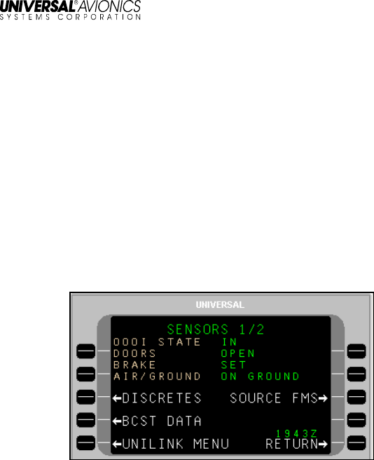
Ground Delay (Optional)
To determine OOOI status, navigate to the SENSORS 1/2 page.
A GROUND DELAY ADVISORY occurs when the configured time on
the Ground Delay Timer expires after doors closed /brakes released
(OUT event) but before Weight-Off-Wheels/Takeoff (OFF event).
The GROUND DELAY ADVISORY annunciation will display at LSK
[5L].
Pressing LSK [5L] will display the DELAY page. The crew can send a
ground delay report by following the procedure listed in the DELAY
section of this manual.
UniLink UL-800/801
Operator’s Manual
32
23-20-06.01
December 2011
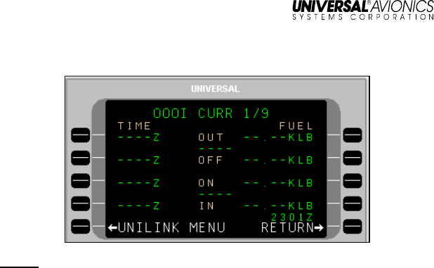
OOOI Current
NOTE: The FUEL fields display the Fuel Onboard quantity from the
FMS when an event is triggered. The FMS will auto-populate
time and fuel information at each event. The crew must
ensure that the FMS fuel information is initialized.
Depending on the installation and configuration, each field may or
may not show the recorded times; a message is sent automatically
when any of these four events take place.
OUT - Door Closed and Parking Brake Released. Includes OUT time,
Fuel Onboard, Departure Airport, and Destination Airport,
OFF - Weight Off Wheels. Includes OFF time, Departure Airport, and
Destination Airport.
ON - WOW. Includes ON time, Departure Airport, and Destination
Airport.
IN - Parking Brake Set and Door Open. Includes IN time, Fuel On
Board, Departure Airport, and Destination Airport.

UniLink UL-800/801
Operator’s Manual
23-20-06.01
33
December 2011
OOOI History
The OOOI event history is captured at the start of the flight. The most
recently stored event is displayed on OOOI HIST 2/9 page. The next
most recent is displayed on OOOI HIST 3/9. A maximum of nine
OOOI HIST pages are available. OOOI HIST is accessed from the
OOOI page by pressing the [PREV] or [NEXT] keys. OOOI data is
retained during a power cycle.
UniLink UL-800/801
Operator’s Manual
34
23-20-06.01
December 2011
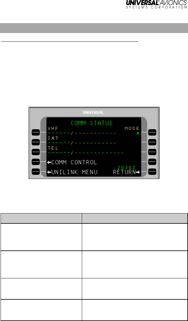
COMM STATUS
Menu Navigation: UNILINK MENU 1/2 > COMM STATUS
The COMM STATUS page displays the current configured status of
available communication media links.
MODE
The MODE field indicates the manner in which ACARS will be used.
• MODE A = POA (Plain Old ACARS)
• MODE B = AOA (AVLC Over ACARS)
Based on the aircraft installation and configuration, all three media
statuses may or may not display. If not configured, the media title will
not display and the position on the page will be empty. The possible
statuses include:
VHF Media Status Reason
COMM / IDLE Communications have been established
with the ground and datalink messages
can be transmitted over VHF. No data is
currently being transmitted.
COMM / SENDING A message is currently in the process of
being transmitted over VHF and UniLink
is waiting for acknowledgement from the
ground.
NOCOMM / NO FREQ UniLink has not selected a frequency for
tuning due to invalid FMS lat/long or no
radio type.
NOCOMM / SCANNING UniLink is automatically selecting a
frequency for tuning in current region
with enabled DSP.

UniLink UL-800/801
Operator’s Manual
23-20-06.01
35
December 2011
VHF Media Status Reason
NOCOMM / CONNECTING UniLink has sent communication to the
ground and is awaiting a reply.
NOCOMM / NO DSP All DSPs have been manually selected
OFF.
NOCOMM / VOICE The VDR is in VOICE mode.
NOTE: Does not apply to UL-801 with
internal VDR.
NOCOMM/VDR INOP VDR inoperative.
NOCOMM/VDR FAULT VDR is reporting a fault.
NOCOMM/MONITORING UniLink has not detected a viable VDL
mode 2 ground station.
NOCOMM VDR/UNAVAIL UniLink has not set the VDR’s protocol
state.
NOCOMM/SUSPEND VHR communications have been
suspended by the crew.
SatCom Media Status Reason
COMM / IDLE SatCom (SAT) communication has been
established and datalink messages can
be transmitted over SatCom. No data is
currently being transmitted.
COMM / SENDING A message is currently in the process of
being transmitted. UniLink is waiting
acknowledgement from the ground.
NOCOMM /SDU UNAVAIL
NOTE: SDU is the Satellite
Data Unit
The SatCom’s system SDU is reporting
that it is unavailable..
NOCOMM / SDU INOP UniLink does not detect the SDU.
NOCOMM / AUTO DELAY UniLink is waiting before trying to
establish a SatCom (SAT) link again.
NOCOMM / TIMEOUT Retries have been exhausted, and Auto
Return to Comm configuration setting is
disabled. A manual Link Test must be
performed, or an uplink received for the
medium to return to COMM.
NOCOMM / CONNECTING A SatCom (SAT) link is in the process of
being established.
NOCOMM/SUSPENDED SatCom (SAT) link has been suspended
by the crew.

UniLink UL-800/801
Operator’s Manual
36
23-20-06.01
December 2011
TEL Media Status Reason
COMM / MDM TIMEOUT UniLink has dialed the phone but a
timeout occurred prior to a
connection being established.
NOTE: Sequential, excessive
timeouts will result in the NOCOMM/
AUTO DELAY display to eventually
activate.
COMM / DIALING UniLink has provided the phone with
the dial string command and is
waiting for the phone to answer.
COMM / CONNECTING The ground has answered the phone
and UniLink is communicating with
the DSP
COMM / IDLE The phone is hung up and no
attempt is currently being made to
use it and SatCom (TEL) is not
suspended or waiting to retry.
COMM / CONNECTED The phone line is connected and
messages can or are currently being
transferred.
COMM / PLEASE WAIT TEL SUSPEND has been manually
activated. UniLink is in the process
of shutting down the connection.
NOCOMM / SUSPENDED SatCom (TEL) has been suspended,
either by the crew or automatically
due to excessive failed attempts.
NOCOMM / AUTO DELAY UniLink is waiting for the configurable
AUTO-DELAY timer to expire before
trying again.
NOCOMM / CONFIG FAIL While CONNECTING with the
ground server, a message is
received saying the configuration
sent by UniLink is invalid. The
SatCom (TEL) system is
permanently shut down. Cycling
UniLink power is required to exit this
state.
UniLink UL-800/801
Operator’s Manual
23-20-06.01
37
December 2011
TEL Media Status Reason
NOCOMM / INIT FAIL The telephone system is not
available for operation. One or both
of the following configuration items
are invalid: Aircraft Registration
Number or Phone Access Number.
NOCOMM / DIALING UniLink exited out of the 5-minute
delay and is in the process of making
another connection attempt.
NOCOMM / PLEASE WAIT TEL SUSPEND has been manually
activated while a connection is in
progress. UniLink is in the process of
shutting down the connection.
NOCOMM / MDM
TIMEOUT UniLink exited out of the 5-minute
delay and while in the process of
making another connection attempt
the UniLink modem has timed out.
UniLink UL-800/801
Operator’s Manual
38
23-20-06.01
December 2011
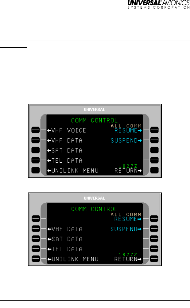
COMM CONTROL
Menu Navigation: UNILINK MENU 1/2 > COMM STATUS > COMM
CONTROL
The COMM CONTROL page provides access to media control pages
and options. Access the COMM CONTROL page by selecting COMM
STATUS, LSK [3L] from the UNILINK MENU 1/2 page. Then select
COMM CONTROL, LSK [4L] from the COMM STATUS page to
display the COMM CONTROL page. The COMM CONTROL page
gives access to VHF VOICE (UL-800 only), VHF DATA, SAT DATA,
and TEL DATA options (as configured and installed)
UL-800 with External VDR
UL-801 with Internal VDR
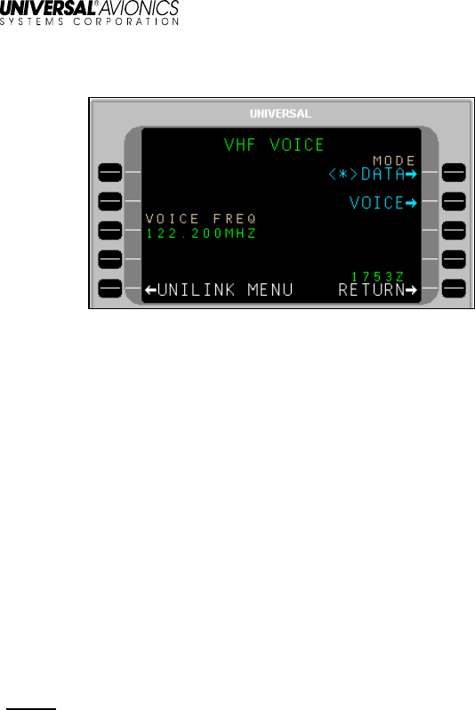
VHF Voice (UL-800 only)
Menu Navigation: UNILINK MENU 1/2 > COMM STATUS > COMM
CONTROL > VHF VOICE
The VHF VOICE option is available if the VHF radio supports voice
communications (does not apply to UL-801 with internal VDR).
UniLink UL-800/801
Operator’s Manual
23-20-06.01
39
December 2011
Pressing VHF VOICE, LSK [1L] from the COMM CONTROL page
displays the VHF VOICE page.
UL-800 with External VDR
The VHF VOICE page is used to enable/disable VHF voice mode.
LSKs [1R] and [2R] allow selection of the MODE as either DATA or
VOICE respectively (an asterisk <*> indicates the selected mode).
DATA Mode - UniLink data communication; no voice communications.
UniLink will tune to the appropriate datalink frequencies only.
VOICE Mode - UniLink no longer communicates via VHF to support
datalink communications. The external VDR is used for voice and
voice frequencies are tuned via VOICE FREQ, LSK [3L].
VHF voice frequency can be tuned from this page if Voice Frequency
Control enabled in configuration. Valid frequency range is:
• If configured for frequency spacing of 25KHz - 118.000 to
136.950
• If configured for frequency spacing of 25KHz/8.33KHz -
118.000 to 136.965 and 136.980 to 136.990
NOTE: The frequency 136.975 is a reserved frequency.

UniLink UL-800/801
Operator’s Manual
40
23-20-06.01
December 2011
VHF Data
Menu Navigation: UNILINK MENU 1/2 > COMM STATUS > COMM
CONTROL > VHF DATA
The VHF DATA option is available if a VHF radio is configured. The
VHF DATA page allows the user to enable or disable the individual
DSPs and provides access to the VHF Frequency (FREQUENCIES)
page. On the COMM CONTROL page press VHF DATA, LSK [2L] to
access the VHF DATA page.
Pressing the LSK adjacent to each DSP toggles the network status
between DISABLED and ENABLED. In the ENABLED status, UniLink
will communicate with the service provider as appropriate. The
DISABLED status prohibits communications with the provider. If all
Service Providers are selected to DISABLED, the VHF status
displayed on the COMM STATUS page will reflect NOCOMM/NO
DSP.
To resolve a VHF NOCOMM problem:
1. On the VHF DATA page, ensure VHF STATE is not set to
SUSPEND.
2. Press LINK TEST SEND. This will initiate a link test to reestablish
VHF communications.
Communications should be reestablished within approximately one
minute and the NOCOMM advisory should no longer be displayed.
If NOCOMM continues to be displayed, this may indicate an
equipment or VHF system network failure not associated with
incorrect frequency usage.

UniLink UL-800/801
Operator’s Manual
23-20-06.01
41
December 2011
STATE
• RESUME: When selected, <
*
> will display. This allows the
VHF system to resume operation.
• SUSPEND: When selected, <
*
> will display. This suspends the
system. While suspended, no VHF transmissions will be
permitted by UniLink and no VHF uplink messages will be
processed.
DSPs
DSPs are configured into UniLink at installation. These selections are
the default selections displayed on the VHF DATA page but may be
overridden by the crew. Care should be taken when overriding these
selections to ENABLED as network access fees may be charged to
your account by the service provider.
DSPs include:
ARINC Worldwide except Europe, North Atlantic and Japan
SITA Worldwide except North America and Japan (Includes
DEPV network in Brazil).
AVICOM Japan
ALL COMM
The ALL COMM function allows the status of all media DATA (VHF,
TEL, SAT) to be set to SUSPEND or RESUME.
• RESUME: When selected, <*> will display. This allows the
communication system (VHF, SAT, TEL) to resume operation.
• SUSPEND: When selected, <*> will display. This suspends the
configured communication system (VHF, SAT, TEL).
Each individual media DATA page has a STATE function that allows
the same RESUME or SUSPEND status to be set just for that specific
link.
UniLink UL-800/801
Operator’s Manual
42
23-20-06.01
December 2011
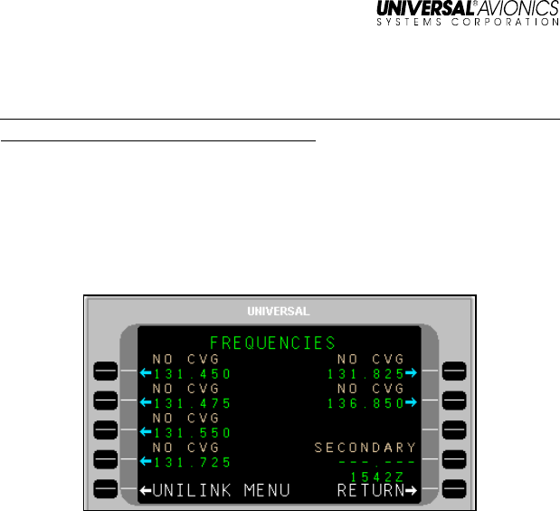
FREQUENCIES
Menu Navigation: UNILINK MENU 1/2 > COMM STATUS > COMM
CONTROL > VHF DATA > FREQUENCIES
The FREQUENCIES page is accessed by selecting the
FREQUENCIES, LSK [3R] on the VHF DATA page. The
FREQUENCIES page displays the primary frequency table and a field
for secondary frequency selection. Normal frequency selection is
controlled automatically by UniLink management logic and user
intervention is not required.
If the UniLink Geographic Database indicates that a DSP has
coverage on a particular frequency at the aircraft’s current location,
the DSP’s name will be displayed above the frequency (ARINC, SITA,
AVICOM, or MULTIPLE). Otherwise NO CVG (No Coverage) will
display.
LSKs allow manual selection of a primary frequency. The <*> icon
indicates the frequency that is currently tuned. The secondary
frequency may be manually entered or uplinked from the ground. Any
entry in the range of 118.000 through 136.975 will be accepted. Only
one frequency, primary or secondary, can be selected at a time.

UniLink UL-800/801
Operator’s Manual
23-20-06.01
43
December 2011
TEL DATA
Menu Navigation: UNILINK MENU 1/2 > COMM STATUS > COMM
CONTROL > TEL DATA
The TEL DATA page is available if an air phone is configured. The
TEL DATA page displays the DSP configured telephone number and
also allows manual override with a different number.
To override the configured telephone number, press NUMBER, LSK
[3L]. This highlights the NUMBER field and allows the displayed
number to be edited or a new number to be entered. An entry of up to
19 digits is acceptable. The new entry will remain active until the
system is restarted, or the number may be restored to the configured
value by pressing the [BACK], then [ENTER] keys. From the
CDU/MCDU keyboard enter P for pause, L for #, or A for *.
Contact your DSP for the appropriate telephone number.
When the SUSPEND option is selected, telephone communication is
suspended and no datalink messages can be sent via telephony.
When RESUME is selected, the telephone can be used for sending
messages. The SUSPEND option is automatically selected if there
have been excessive unsuccessful attempts at sending messages via
telephony to the ground. Any manual selection will override any
automatically set condition. A <*> indicates the current state
STATE
• RESUME: When selected, <
*
> will display. This allows the TEL
system to resume operation.
• SUSPEND: When selected, <
*
> will display. This suspends the
system. While suspended, no TEL transmissions will be
permitted by UniLink and no TEL uplink messages will be
processed.

UniLink UL-800/801
Operator’s Manual
44
23-20-06.01
December 2011
Telephone Link Test
This feature provides the operator the ability to test the telephone link
by sending a downlink over the telephone system and then displays
the link test status. Run the test by selecting
LINK TEST
SEND, LSK
[4R]. The state of the telephone link test will display on the line above.
Once the test is complete, the telephone status is displayed on the
COMM STATUS page. The displayed status is described in the
COMM Status section of this manual.
SAT DATA
Menu Navigation: UNILINK MENU 1/2 > COMM STATUS > COMM
CONTROL > SAT DATA
The SAT DATA page allows the user to send a SatCom link test.
SatCom Datalink Test
This feature provides the operator the ability to test the SatCom link
by sending a downlink over the SatCom system and then display the
link test status. Run the test by selecting LINK TEST SEND, LSK
[4R]. While the test is running, the state of the SatCom link test is
displayed on the line above.
Once the test is complete, the SatCom status is displayed on the
COMM STATUS page. The displayed status is described in the
COMM Status section of this manual.
STATE
• RESUME: When selected, <
*
> will display. This allows the
SAT system to resume operation.
• SUSPEND: When selected, <
*
> will display. This suspends the
SAT system. While suspended, no SAT transmissions will be
permitted by UniLink and no VHF uplink messages will be
processed.

UniLink UL-800/801
Operator’s Manual
23-20-06.01
45
December 2011
Text Weather Report Requests
Menu Navigation: UNILINK MENU 1/2 > TEXT WX > TEXT WX REQUEST
The TEXT WX REQUEST page allows the user to request four types
of text weather reports from up to six locations.
TERMINAL weather received from this request will apply to stations
entered on this page, and will include both actual and forecast
conditions for each station.
WINDS (Winds Aloft), SIGMETS (Significant Meteorological
information), and PIREPS (Pilot Weather Reports), and will apply to
the flight plan route from the FMS. If a manual data entry is made in
STATIONS fields (LSKs [1L & 2L]), the Winds Aloft will apply to
waypoints along the great circle route from the aircraft’s present
position to the airport identifier. Stored text weather messages are
accessed via the VERIF OPS WX page (accessed from the
MESSAGE LOGS page).
To request Text Weather:
1. Press TEXT WX, LSK [1R] on UNILINK MENU 1/2 page.
2. On the TEXT WX REQUEST page, enter up to six reporting
stations (STATIONS) using LSKs [1L] and [2L], and then press
the [ENTER] key. The first station will default to the FMS
destination airport identifier.
NOTE: When exiting this page, all stations entered are cleared.
3. Press TYPES, LSK [1R] to choose the type of reports to receive.
The WX TYPE SELECT page will display.

UniLink UL-800/801
Operator’s Manual
46
23-20-06.01
December 2011
4. Multiple report types may be selected. Press the LSK adjacent the
report types to request.
NOTE: Terminal is selected by default (indicated by <
*
>).
5. Press RETURN to go back to the TEXT WX REQUEST page. An
asterisk will display next to the selected report types.
6. Press the SEND LSK to place the request in queue for
transmission.
NOTE: DATA REQUIRED displays if no reporting stations have been
entered.
UniLink UL-800/801
Operator’s Manual
23-20-06.01
47
December 2011
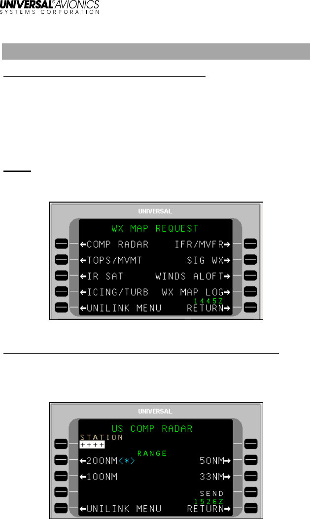
Weather Map Requests
Menu Navigation: UNILINK MENU 1/2 > WX MAPS
The UNILINK MENU 1/2 page allows the user to request and view
graphical weather maps. Maps are available only over an airborne
telephony link and the WX MAP REQUEST page is only available
when the WX MAPS configuration selection is enabled. Graphic
weather maps are available on Flat Panel Control Display Units
(FPCDU) having graphics capability.
NOTE: WX MAP REQUEST page can be accessed either from
UNILINK MENU 1/2 (WX MAPS, LSK [2R]) or the WX MAPS
LSK on the TEXT WX REQUEST page.
US Composite Radar
Menu Navigation: UNILINK MENU (1/2) > WX MAPS> COMP RADAR
The US COMP RADAR page allows the user to request Composite
Radar Weather maps at specified weather stations and International
Civil Aviation Organization (ICAO) airports.
UniLink UL-800/801
Operator’s Manual
48
23-20-06.01
December 2011
To request a Composite Radar graphic:
1. Press COMP RADAR, LSK [1L] on the WX MAP REQUEST
page. The US COMP RADAR page will display.
2. Enter an airport identifier in the STATION field and press
[ENTER], or accept the default destination airport identifier from
the FMS.
NOTE: If an incomplete identifier is entered, the message TOO FEW
CHARACTERS will display and the field will flash. Pressing
the LSK and re-entering a complete identifier will correct the
error.
3. Select a Map Range using the range LSK options. A <*> indicator
will display adjacent to the selected range.
NOTE: The selected range is retained through system power cycles.
4. Press SEND, LSK [4R] to place the request in queue for
transmission.
NOTE: The SEND LSK will not be active and DATA REQUIRED
displays if no airport identifier has been entered.
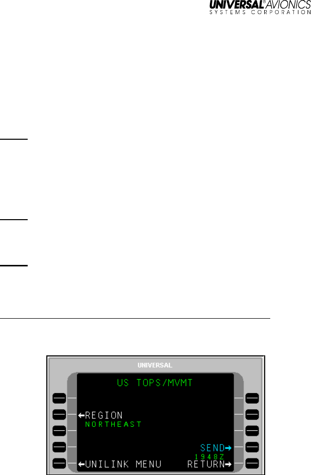
US Radar Tops and Movement
Menu Navigation: UNILINK MENU 1/2 > WX MAPS > TOPS/MVMT
The US TOPS/ MVMT page is used to request US Radar Tops and
Movement graphics from a specific geographical area.

UniLink UL-800/801
Operator’s Manual
23-20-06.01
49
December 2011
To request a Tops and Movement graphic:
1. Press TOPS/ MVMT, LSK [2L] on the WX MAP REQUEST page.
The US TOPS/MVMT page will display
2. Press REGION, LSK [2L] to display the REGION-
US TOPS/MVMT
page.
3. Select a region LSK option for display and return to the US
TOPS/MVMT page. The last selection will remain through system
power cycles.
4. Press the SEND LSK to place the request in queue for
transmission.
UniLink UL-800/801
Operator’s Manual
50
23-20-06.01
December 2011
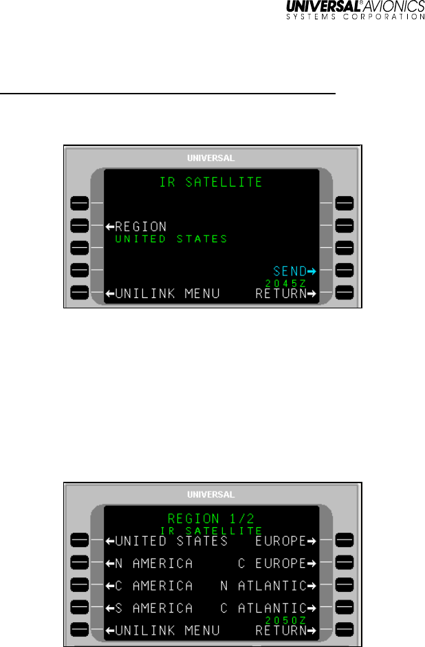
IR SATELLITE
Menu Navigation: UNILINK MENU 1/2 > WX MAPS > IR SAT
The IR SATELLITE page allows the user to request worldwide IR
Satellite Weather maps.
To request an IR Satellite Map graphic:
1. Press IR SAT, LSK [3R] on the WX MAP REQUEST page. The IR
SATELLITE page will display.
2. Press REGION, LSK [2L] to display the REGION-
IR SATELLITE
1/2 page. If needed, press NEXT to display the REGION-
IR
SATELLITE
2/2 page.
3. Select a region for display and return to the IR SATELLITE page.
The last selection will remain through system power cycles.
4. Press the SEND LSK to place the request in queue for
transmission.
UniLink UL-800/801
Operator’s Manual
23-20-06.01
51
December 2011
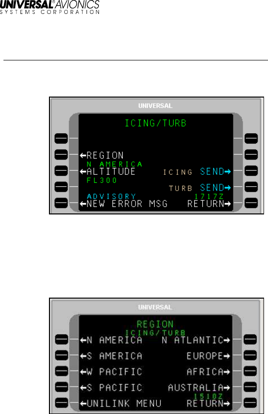
Icing/Turbulence Potential
Menu Navigation: UNILINK MENU 1/2 > WX MAPS > ICING/TURB
The ICING TURB page is used to request worldwide icing potential or
turbulence potential maps.
To request an Icing Potential or Turbulence Potential Map:
1. Press ICING/TURB, LSK [4L] on the WX MAP REQUEST page.
The ICING/TURB page will display.
2. Press REGION, LSK [2L] to display the REGION-
ICING TURB
page.
3. Select a region for display and return to the ICING/TURB page.
The last selection will remain through system power cycles.
4. Press ALTITUDE to access the ALTITUDE-
ICING/TURB
page.
5. Select an altitude option by pressing the adjacent LSK and return
to the ICING/TURB page. The last selection will remain through
system power cycles.
UniLink UL-800/801
Operator’s Manual
52
23-20-06.01
December 2011
6. Press
ICING
SEND or
TURB
SEND to place the request in queue
for transmission.
UniLink UL-800/801
Operator’s Manual
23-20-06.01
53
December 2011
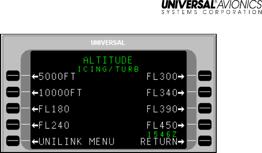
IFR/MVFR
Menu Navigation: UNILINK MENU 1/2 > WX MAPS > IFR/MVFR
The IFR/MVFR page is used to request worldwide IFR/MVFR maps.
To request an IFR/MVFR Map:
1. Press IFR/MVFR, LSK [1R] on the WX MAP REQUEST page.
The IFR/MVFR page will display.
2. Press REGION, LSK [2L] to display REGION-
IFR/MVFR
page.
3. As needed, press the [NEXT] key to display the REGION 2/3 and
3/3 pages. Select a region and return to the IFR/MVFR page.
NOTE: The last selection will be retained through system power
cycles.
4. Press SEND, LSK [4R] to place the request in queue for
transmission.
UniLink UL-800/801
Operator’s Manual
54
23-20-06.01
December 2011
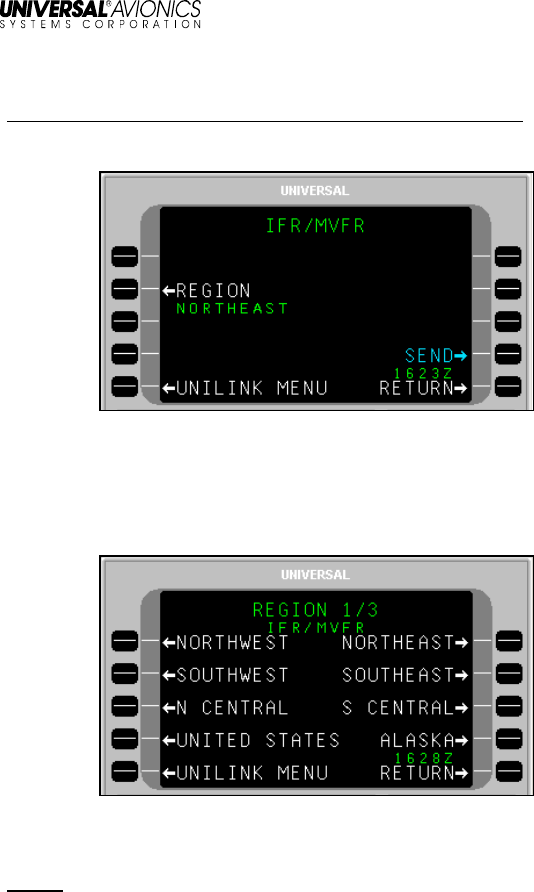
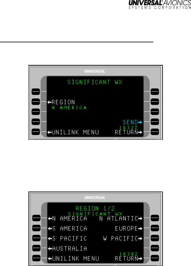
Significant Weather
Menu Navigation: UNILINK MENU 1/2 > WX MAPS > SIG WX
The SIGNIFICANT WX page allows the user to request High Level
Significant Weather Maps.
To request a Significant Weather Map:
1. Press SIG WX, LSK [2R] on the WX MAP REQUEST page. The
SIGNIFICANT WX page will display.
2. Press REGION, LSK [2L] to display the REGION-
SIGNIFICANT WX
1/2 page.
3. As needed, press NEXT to display REGION-
SIGNIFICANT WX
2/2
page. Select a region for display and return to the Significant
Weather page. The last selection will remain through system
power cycles.
4. Press SEND, LSK [4R] to place the request in queue for
transmission.
UniLink UL-800/801
Operator’s Manual
23-20-06.01
55
December 2011
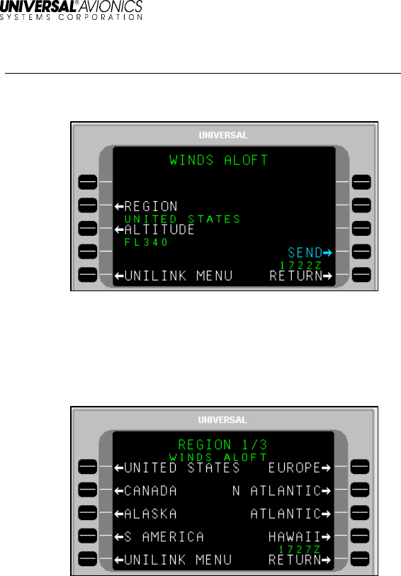
Winds Aloft
Menu Navigation: UNILINK MENU 1/2 > WX MAPS > WINDS ALOFT
The WINDS ALOFT page allows the user to request the most current
worldwide Winds Aloft maps by region.
To request The Winds and Temperature Aloft graphic:
1. Press WINDS ALOFT, LSK [3R] on the WX MAPS REQUEST
page. The WINDS ALOFT page will display.
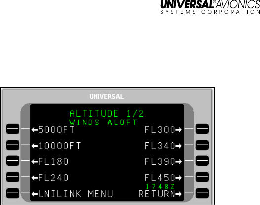
2. Press REGION, LSK. [2L]. The REGION-
WINDS ALOFT
1/3 page
will display.
3. As needed, press the [NEXT] key to display the REGION-
WINDS
ALOFT
pages 2/3 and 3/3. Select a region for display by pressing
the adjacent LSK and return to the WINDS ALOFT page. The last
selection will remain through system power cycles.
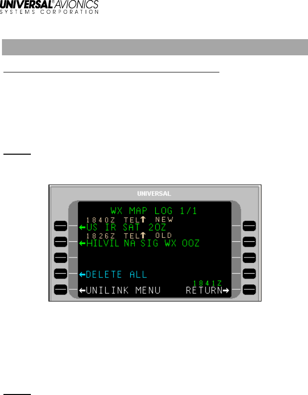
4. Press the ALTITUDE LSK to access the ALTITUDE-
WINDS ALOFT
1/2 page.
UniLink UL-800/801
Operator’s Manual
56
23-20-06.01
December 2011
5. As needed, press the [NEXT] key to display ALTITUDE-
WINDS
ALOFT
page 2/2. Select an altitude by pressing the adjacent LSK
and return to the WINDS ALOFT page. The last selection will
remain through system power cycles.
6. Press the SEND LSK to place the message in queue for
transmission.
UniLink UL-800/801
Operator’s Manual
23-20-06.01
57
December 2011
Weather Map Log
Menu Navigation: UNILINK MENU 1/2 > WX MAP LOG
The WX MAP LOG pages allow the user to select previously uplinked
weather graphics for viewing on a CDU/MCDU, MFD, EFI-890R, or
for deletion. Weather map titles are listed in the order they are
received with the last map received appearing first. UniLink stores up
to 32 maps.
NOTE: The WX MAP LOG page can be accessed from UNILINK
MENU 1/2, TEXT WX REQUEST page, or WX MAP
REQUEST page.
To display a weather map:
1. Press the WX MAP LOG, LSK [4R] on the WX MAP REQUEST
page, LSK [3R] on UNILINK MENU 1/2 page, or LSK [4L] on the
TEXT WX REQUEST page.
2. Press the left-hand LSK adjacent the desired weather map.
NOTE: Pressing any key while the map is displayed will return the
display to the MAP LOG page.
To display a new weather map after receiving a NEW WX MAP RCVD
message:
1. Press the UNILINK LSK on the DATA 1/X page or the MESSAGE
1/X page to access the UNILINK MENU page.
2. Press NEW WX MAP advisory prompt to view the weather map.

UniLink UL-800/801
Operator’s Manual
58
23-20-06.01
December 2011
To delete an uplinked weather map:
1. Select the map to delete by pressing the adjacent right-hand LSK.
This places the cursor over the map and displays the delete
option window.
2. Press the DELETE LSK to delete the map.
3. To delete all uplinked weather maps, select the DELETE ALL
option. DELETE ALL only appears on the WX MAP LOG 1/X
page.
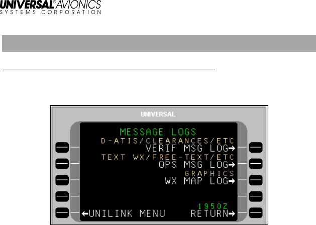
UniLink UL-800/801
Operator’s Manual
23-20-06.01
59
December 2011
Message Logs
Menu Navigation: UNILINK MENU 1/2 > MSG LOGS
The MESSAGE LOGS page allows the user to view, print, or delete
messages.
Verified Messages – The VERIF MSGS 1/X page displays all ATS or
other verified messages. Press VERIF MSG LOG, LSK [1R] to access
the VERIF MSGS page.
Operations Messages – The OPS MSGS 1/X page displays all
unverified messages (messages containing unverified data). Press
OPS MSG LOG, LSK [2R] to access the OPS MSGS page.
WX Map Uplinks – The WX MAP LOG 1/X page displays all weather
graphic uplinks. Press WX MAP LOG, LSK [3R] to access the WX
MAP LOG pages.
Message titles will appear on these pages in the inverse order they
are received. The newest message will appear first. If more than one
page of message titles exists, use the [PREV] and [NEXT] keys to
cycle through the pages. A new message may be viewed from any
UNILINK page by pressing the NEW MSG ADVISORY LSK.
Messages may be viewed by selecting the left-hand LSK adjacent the
message title.
To delete all messages from a message log, press the DELETE ALL
LSK. This prompt is only displayed on page 1 of the message log
pages.

UniLink UL-800/801
Operator’s Manual
60
23-20-06.01
December 2011
Verified Messages
Menu Navigation: UNILINK MENU 1/2 > MSG LOGS > VERIF MSG LOG
The VERIF MSGS page displays all ATS, Clearance, and other
verified messages. Press VERIF MSG LOG, LSK [1R] to access the
VERIF MSGS page. The total number of pages increases as verified
messages are received. If more than one page of message titles
exists, use the [PREV] and [NEXT] keys to cycle through the pages.
LSKs [1L] through [3L] on page 1/X and [1L] through [4L] on
succeeding pages display ATS and other verified message titles.
Status information is displayed above the message title and includes
the time received, transmission medium, uplink (¨) or downlink (Î)
indicator, and status.
Messages are sorted with the newest at the top of the list. Pressing
the left-hand LSK adjacent a message displays the corresponding
message if the message contains viewable text.
Pressing a right-hand LSK displays the message pop-up window for
the corresponding message and allows the deletion or printing of the
message (see the Delete or Print a Message section later in this
manual). Any key press other than [1R] or [2R] will exit the pop-up
window.
DELETE ALL, LSK [4L] on page 1/X is used to delete all uplinked
messages from the displayed page.
RETURN, LSK [5R] returns the display to the MESSAGE LOGS page.

UniLink UL-800/801
Operator’s Manual
23-20-06.01
61
December 2011
Message Status Descriptions
NEW The uplink is available in the log and has not been
viewed.
OLD The uplink has been viewed and does not require and
acknowledgement.
ACK RQD The uplink has been viewed and the ACARS ATS
facility requests that the crew manually acknowledge
receipt of the message.
ACKED The uplink has been viewed and an acknowledgement
has been sent.
SENT The downlink has been successfully transmitted at the
indicated time.
SENDING The downlink is being transmitted via the indicated
medium (VHF, SAT, TEL)
DEFERRED The downlink message lacks priority for immediate
transmission and is deferred pending availability of
other downlink messages with which it can be bundled
for transmission.
EXPIRED The downlink message ceased being valid or useful
before it could be successfully transmitted (as
determined by the downlink message timer).
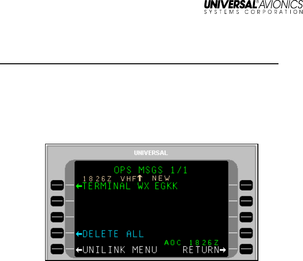
UniLink UL-800/801
Operator’s Manual
62
23-20-06.01
December 2011
Operations Messages
Menu Navigation: UNILINK MENU(1/2 > MSG LOGS > OPS MSG LOG
The OPS MSGS page displays all operations unverified uplink
messages including Text Weather and Free Text. Press OPS MSG
LOG, LSK [2R] to access the OPS MSGS page. The total number of
pages increases as uplink messages are received. If more than one
page of message titles exists, use the [PREV] and [NEXT] keys to
cycle through the pages.
LSKs [1L] through [3L] on page 1/X and [1L] through [4L] on
succeeding pages display unverified uplink message titles. Status
information is displayed above the message title and includes the time
received, transmission medium, uplink (¨) or downlink (Î) indicator,
and status.
Messages are sorted with the newest at the top of the list. Pressing a
left-hand LSK displays the OPS MSG page for the corresponding
message if the message contains viewable text.
Pressing a right-hand LSK displays the message pop-up window for
the corresponding message and allows the deletion or printing of the
message (see the Delete or Print a Message section later in this
manual). Any key press other than [1R] or [2R] will exit the pop-up
window.
DELETE ALL, LSK [4L] on page 1/X is used to delete all messages
from the log.
RETURN, LSK [5R] returns the display to the MESSAGE LOGS page.

UniLink UL-800/801
Operator’s Manual
23-20-06.01
63
December 2011
Message Status Descriptions
NEW The uplink is available in the log and has not been
viewed.
OLD The uplink has been viewed and does not require an
acknowledgement.
ACK RQD The uplink has been viewed and the customer AOC
facility requests that the crew manually acknowledge
receipt of the message.
ACKED The uplink has been viewed and an acknowledgement
has been sent.
SENT The downlink has been successfully transmitted at the
indicated time.
SENDING The downlink is being transmitted via the indicated
medium (VHF, SAT, TEL)
DEFERRED The downlink message lacks priority for immediate
transmission and is deferred pending availability of
other downlink messages with which it can be bundled
for transmission.
EXPIRED The downlink message ceased being valid or useful
before it could be successfully transmitted (as
determined by the downlink message timer).
Weather Map Log
(See the Weather Map Log section).
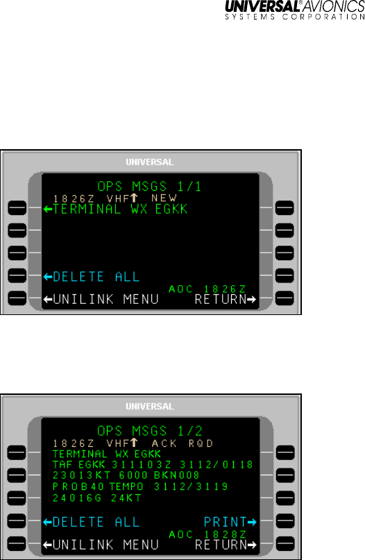
UniLink UL-800/801
Operator’s Manual
64
23-20-06.01
December 2011
View Message - Detailed Message Screen
A detailed message screen will display when a message is viewed by
selecting a corresponding message LSK or via the NEW MESSAGE
ADVISORY.
1. Press the [PREV] and [NEXT] keys to cycle through the pages.
2. In the message log page (VERIF MSGS, OPS MSGS, or WX
MAP LOG), press the left LSK adjacent a message title to view a
message. A detailed message screen or weather graphic will
display.
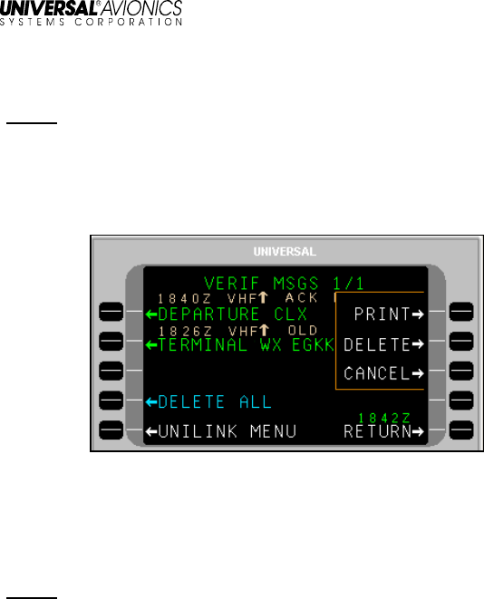
UniLink UL-800/801
Operator’s Manual
23-20-06.01
65
December 2011
Delete or Print a Message
NOTE: This procedure is available on the VERIF MSGS, OPS MSGS,
and WX MAP LOG pages.
1. Access the desired message log page.
2. Press the right-hand LSK of a message. This activates the
message pop-up window.
3. Press the PRINT LSK to print the message (a printer must be
installed and configured).
4. Press the DELETE LSK to delete the message.
5. Press the CANCEL LSK to exit the pop-up menu.
NOTE: Any LSK or CDU keyboard selection other than LSKs [1R] or
[2R] removes the pop-up window.
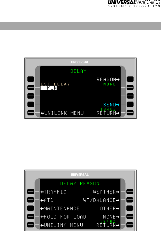
UniLink UL-800/801
Operator’s Manual
66
23-20-06.01
December 2011
DELAY
Menu Navigation: UNILINK MENU 2/2 > DELAY
The DELAY page is used to report estimated ground delays prior to
take off.
To send a Ground Delay report:
1. Press DELAY, LSK [1L] from UNILINK MENU page 2/2 or from
any page when selecting the GROUND DELAY advisory.
2. With EST DELAY (estimated delay) active, enter the estimated
time in minutes and press [ENTER].
3. Press REASON, LSK [1R] to access the DELAY REASON page.
4. Press the LSK adjacent the appropriate reason option. The
display will return to the DELAY page. NONE will be selected by
default if no entry is made on this page.
5. Press SEND, LSK [4R] to place the message in queue for
transmission.
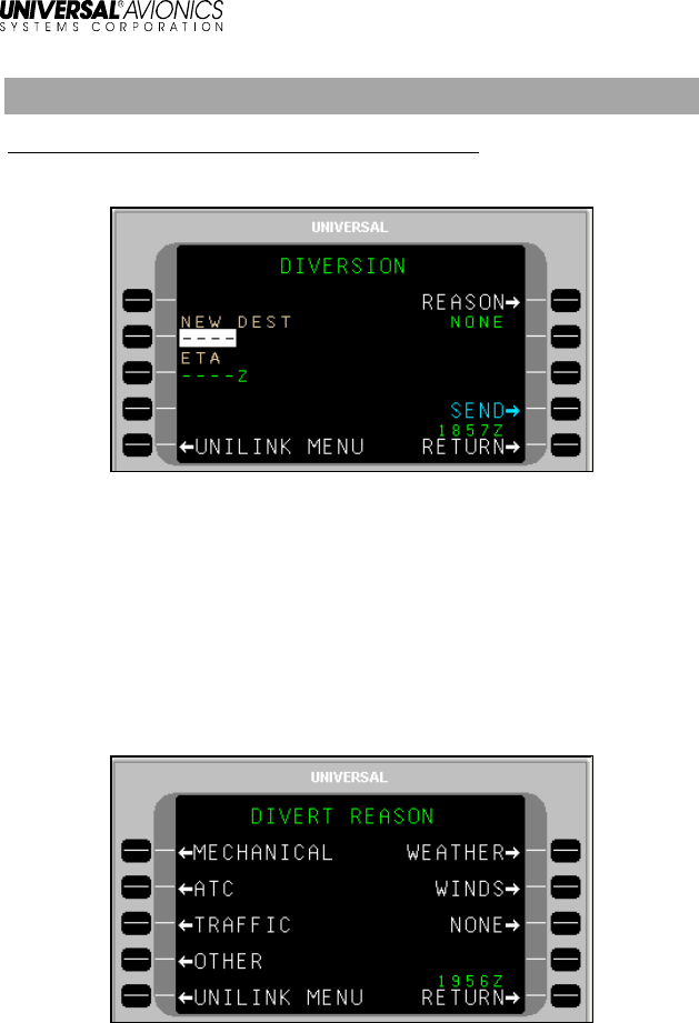
UniLink UL-800/801
Operator’s Manual
23-20-06.01
67
December 2011
DIVERSION
Menu Navigation: UNILINK MENU 2/2 > DIVERSION
The DIVERSION page is used to send a revised destination message.
To send a diversion message:
1. Press DIVERSION, LSK [2L] from UNILINK MENU page 2/2. The
DIVERSION page will display.
2. With NEW DEST active, enter a destination and press [ENTER]
or verify new destination data from the FMS.
3. If not active, press ETA (LSK [3L]), enter an ETA, and press
[ENTER]; or verify ETA data from the FMS.
4. Press REASON, LSK [1R] to access the DIVERT REASON page.
5. Press the LSK adjacent the appropriate Divert Reason option and
return to the DIVERSION page. NONE will be selected by default
if no entry is made on this page.
6. Press the SEND LSK to place the report or message in queue for
transmission.

UniLink UL-800/801
Operator’s Manual
68
23-20-06.01
December 2011
NOTE: During a given flight leg, the first press sends a Diversion
Report downlink. Each subsequent press sends a revised
Diversion Report downlink.
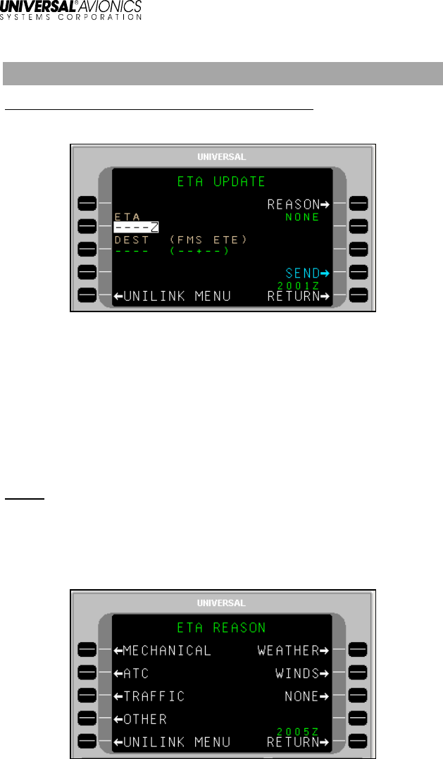
UniLink UL-800/801
Operator’s Manual
23-20-06.01
69
December 2011
ETA UPDATE
Menu Navigation: UNILINK MENU 2/2 > ETA UPDATE
The ETA UPDATE page is used to send an ETA update message.
To send an ETA Update message:
1. Press ETA UPDATE, LSK [3L] from UNILINK MENU page 2/2.
The ETA UPDATE page will display.
2. With ETA active, enter an ETA and press [ENTER], or verify ETA
data from the FMS.
3. If not active, press DEST, LSK [3L], enter a destination airport
identifier, and press [ENTER]; or verify the default identifier from
the FMS.
NOTE: This field will display dashes if the destination airport is not
available.
The FMS ETE field is provided for reference only and displays the
current computed FMS estimated time enroute.
4. Press REASON, LSK [1R] to access the ETA REASON page.

UniLink UL-800/801
Operator’s Manual
70
23-20-06.01
December 2011
5. Press the LSK adjacent the appropriate ETA Reason and return
to the ETA UPDATE page.
6. Press the SEND LSK to place the report or message in queue for
transmission.
NOTE: During a given flight leg, the first press sends a Diversion
Report downlink. Each subsequent press sends a revised
Diversion Report downlink.
SELCAL
Menu Navigation: UNILINK MENU 2/2 > SELCAL
The SELCAL (Selective Call) CONTACT page displays the Ground
Voice Request frequency. The SELCAL option on the UNILINK MENU
will only display if a voice frequency request is received and the
SELCAL advisory has been selected. This prompt is hidden at the
beginning of each flight leg.
Press RETURN to return to the MAIN MENU or the CDU/MCDU page
displayed when the ADVISORY was pressed to access the SELCAL
contact message.
NOTE If not currently in a UNILINK page when the SELCAL request
is received, the MSG annunciation will flash in the upper right-
hand corner of the CDU/MCDU. Navigate to the UNILINK
MENU page to access the SELCAL option.
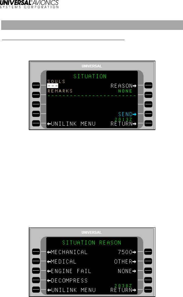
UniLink UL-800/801
Operator’s Manual
23-20-06.01
71
December 2011
SITUATION
Menu Navigation: UNILINK MENU 2/2 > SITUATION
The SITUATION page permits the sending of emergency report
messages for mechanical and medical emergencies.
All situation reports include FUEL ONBD and ENDURANCE data from
FMS FUEL page 2/5.
To make the report:
1. Press SITUATION, LSK [2R] on UNILINK MENU page 2/2. The
SITUATION page will display.
2. With SOULS active, enter the number of persons onboard and
press [ENTER].
3. If not active, press REMARKS, LSK [2L] (optional) and, enter
information as needed. Up to 24 characters may be entered.
4. Press REASON, LSK [1R] to access the SITUATION REASON
page.
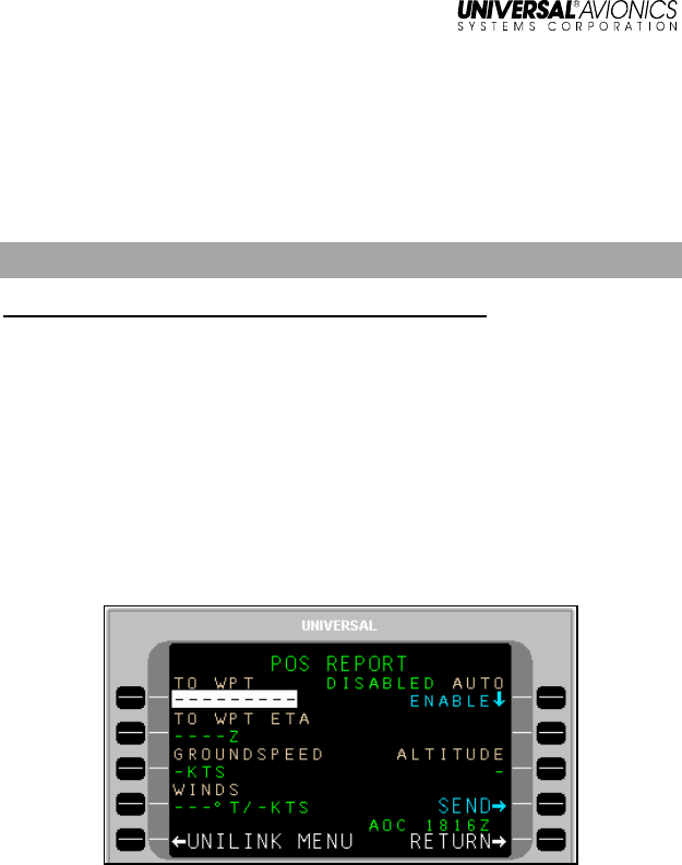
UniLink UL-800/801
Operator’s Manual
72
23-20-06.01
December 2011
5. Press the LSK adjacent the appropriate reason and return to the
SITUATION page. If no selection is made, the REASON field will
default to NONE.
6. Press the SEND LSK to place the report in queue for
transmission.
POS REPORT
Menu Navigation: UNILINK MENU 2/2 > POS REPORT
The POS REPORT page is used to modify Position Report data prior
to sending, and to enable and disable the Auto Position report (AUTO)
function.
Data on this page is prefilled FMS/ADC data. Normally this data will
be valid for the Position Report; however, temporary manual entries
are possible for the current manually initiated transmission only.
To make the report:
1. Press POS REPORT, LSK [3R] from UNILINK MENU page 2/2.
The POS REPORT page will display.
2. With TO WPT active, enter a waypoint name and press [ENTER].
3. The TO WPT ETA (LSK [2L]) is supplied by the FMS. To change,
if not active, press and enter up to four digits (Time is UTC time).
Press [ENTER].
4. If not active, press GROUNDSPEED, LSK [3L] and enter up to
three digits. Press [ENTER].
5. If not active, press WINDS, LSK [4L] and enter three digits for
wind direction. Press [ENTER] to advance the cursor to the
velocity field and enter up to three digits. Press [ENTER].
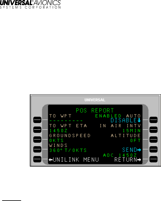
UniLink UL-800/801
Operator’s Manual
23-20-06.01
73
December 2011
6. If not already active, press ALTITUDE, LSK [3R] and enter current
altitude if no ADC Altitude is available. Press [ENTER].
7. Press the SEND LSK to place the report in queue for
transmission.
Automatic Position Reporting
1. Press AUTO, LSK [1R] to toggle the Automatic Report function to
ENABLED or DISABLED. The current status is displayed to the
left of AUTO.
2. If AUTO is set to ENABLED, press IN AIR INTV, LSK [2R] to set
the report interval time (default is based on configuration setting).
Press [ENTER].
NOTE: The IN AIR INTV option is not present if AUTO is set to
DISABLED.
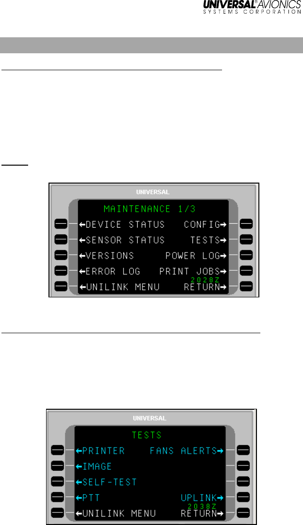
UniLink UL-800/801
Operator’s Manual
74
23-20-06.01
December 2011
Maintenance
Menu Navigation: UNILINK MENU 2/2 > MAINTENANCE
Maintenance pages are used to access UniLink maintenance related
functions. No operation-related functions are performed on this page
or subpages. Operational tests can be conducted via the TESTS
option.
From the UniLink Menu 2/2, press MAINTENANCE, LSK [4L]. The
MAINTENANCE 1/3 page will display.
NOTE: See the associated UniLink Installation Manual for installation
and maintenance procedures
.
Tests
Menu Navigation: UNILINK MENU 2/2 > MAINTENANCE > TESTS
There are several tests available to exercise the functionality of
UniLink. They include PRINTER Test, IMAGE Test, UniLink SELF-
TEST, PTT, FANS ALERTS, and UPLINK test.
Press TESTS, LSK [2R] on the MAINTENANCE page to display the
TESTS page.
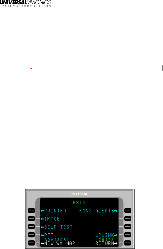
UniLink UL-800/801
Operator’s Manual
23-20-06.01
75
December 2011
Printer Test
Menu Navigation: UNILINK MENU (2/2) > MAINTENANCE > TESTS >
PRINTER
If a printer is connected and configured, selection of PRINTER, LSK
[1L] will send test message text to the printer. If there is no printer
configured, the PRINTER option will not be displayed.
When PRINTER is selected, a pop-up window PRINTER TEST IN
PROGRESS” is displayed. When complete, the pop-up window is no
longer displayed.
The following will be printed:
THIS IS NOT AN UPLINK. THIS IS AN INTERNALLY
GENERATED PRINTER TEST MESSAGE. !"#$%&'()*+,-
./0123456789:;<=>?@ABCDEFGHIJKLMNOPQRSTUVWXYZ[\]^_`
{|}~;
Image Test
Menu Navigation: UNILINK MENU 2/2 > MAINTENANCE > TESTS > IMAGE
Selection of IMAGE, LSK [2L] is used to display a test image. While
the test image is being displayed, any key push will cause the display
to return to the MAINTENANCE page. Image Test is not available
when the aircraft is in the air.
When IMAGE is selected, a pop-up window with the message IMAGE
TEST IN PROGRESS will display. When the test is complete, an
ADVISORY will display on the CDU and NEW WX MAP is displayed
adjacent LSK [5L] (LSK for MCDU may be different).
Press NEW WX MAP, LSK [5L] to display the generated test weather
image. A test weather map will display with the title IMAGE BUS
TEST.

UniLink UL-800/801
Operator’s Manual
76
23-20-06.01
December 2011
NOTE: This image will display on an EFI-890R or MFD if installed
and configured.
To exit the image, press RTN, LSK [5R].The display returns to the
TESTS page (NEW WX MAP and ADVISORY are no longer
displayed).
UniLink Self-Test
Menu Navigation: UNILINK MENU(2/2 > MAINTENANCE > TESTS > SELF-
TEST
Selection of SELF-TEST, LSK [3L] places the system in a power up
test mode.
When the test is selected a pop-up window requesting to CONFIRM
or CANCEL the test is displayed. Selecting CANCEL closes the pop-
up window and returns to the current display. Selecting CONFIRM
reboots UniLink. The message UNILINK/FMS COMM ERROR
RESELECT UNILINK is displayed. During the period of reboot, the
UNILINK displayed on the CDUMCDU is not selectable. When the
test is complete, UNILINK will be selectable. Selecting UNILINK will
display UNILINK MENU page 1/2.
PTT (Push-To-Talk) (UL-801 only)
Menu Navigation: UNILINK MENU 2/2 > MAINTENANCE. > TESTS > PTT
If available, this test commands the radio to transmit for 3 seconds. A
pop-up window PTT TEST IN PROGRESS will display for 3 seconds.
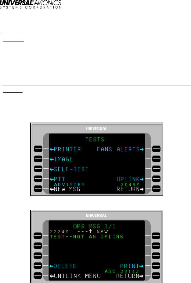
UniLink UL-800/801
Operator’s Manual
23-20-06.01
77
December 2011
FANS ALERTS
Menu Navigation: UNILINK MENU 2/2 > MAINTENANCE > TESTS > FANS
ALERTS
1. Press FANS ALERTS, LSK [1R]. A pop-up window FANS
DISCRETES NOT CONFIGURED will display, then close.
Uplink Test
Menu Navigation: UNILINK MENU 2/2 > MAINTENANCE > TESTS >
UPLINK
Selection of UPLINK, LSK [4R] causes a test uplink to be placed in
the OPS message log, generating a NEW MSG advisory at the
bottom of the display.
1. Press NEW MSG, LSK [5L] to display message.
2. If desired press PRINT, LSK [4R] to print the screen (Printer must
be configured).
3. Press DELETE, LSK [4L] to delete test message. The display will
return to the TESTS page.

UniLink UL-800/801
Operator’s Manual
78
23-20-06.01
December 2011
UniLink UL-800/801
Operator’s Manual
23-20-06.01
79
December 2011
GLOSSARY
Acronym/Abbreviation
/Term Description
ACARS Aircraft Communication Addressing and
Reporting System
ACK Acknowledgement
ADC Air Data Computer
ADS-C Automatic Dependent Surveillance -
Contract
AFN ATS Facilities Notification
ALT Altitude
AOA ACARS Over Aviation VHF Link Control
(AVLC)
AOC Aeronautical (airline) Operational Control
ARINC Aeronautical Radio, Inc. (data interface
format standard)
ATC Air Traffic Control
ATIS Automatic Terminal Information Service
(see D-ATIS)
ATM Air Traffic Management
ATN Aeronautical Telecommunications Network
ATS Air Traffic Services
AVLC Aviation VHF Link Control
CDA Current Data Authority
CDB Customer Database
CDU Control Display Unit
Circuit Mode Data A full duplex bi-directional communication
link in which data is transmitted and
received simultaneously. A hand shake
must be established prior to data being
exchanged. Supported by a UniLink RS-232
port configured for TEL
UniLink UL-800/801
Operator’s Manual UniLink UL-800/801
Operator’s Manual
80 23-20-06.01
December 2011
Acronym/Abbreviation
/Term Description
CLX Clearance
CM Configuration Module
CMU Communications Management Unit
CNS Communication Navigation Surveillance
COMM Communication
CPDLC Controller-Crew Datalink Communications
CRC Cyclic Redundancy Check
CSC Common Signaling Channel
CSDB Commercial Standard Data Bus (data
interface format standard)
CTS Clear to Send
CVFDR Cockpit Voice and Flight Data Recorder
(UASC)
CVR Cockpit Voice Recorder
D-ATIS Digital Automatic Terminal Information
System (also referred to as ATIS)
DEPT CLX Departure Clearance
DM Downlink Message
DP Display Processor
DTU Data Transfer Unit (UASC)
DTU-100 Data Transfer Unit – 100 (UASC)
DSP Datalink Service Provider (sometimes
referred to as DLSP)
EFB Electronic Flight Bag
EFI Electronic Flight Instrument
EFI-890R Electronic Flight Instrument – 890R (UASC)
ETA Estimated Time of Arrival
ETD Estimated Time of Departure
EUROCAE European Organization for Civil Aviation
Equipment
EXP Expected

UniLink UL-800/801
Operator’s Manual
23-20-06.01
81
December 2011
Acronym/Abbreviation
/Term Description
FAA Federal Aviation Administration
FANS Future Air Navigation Systems
FL Flight Level
FLT NO Flight Number
FMC Flight Management Computer
FMS Flight Management System
FPL Flight Plan
FREQ Frequency
GND SPD Ground Speed
GNSS Global
GPS Global Positioning System
HS High Speed
ICAO International Civil Aviation Organization
ID Identification, Identifier
IFR Instrument Flight Rules
IOP Input/Output Processor
I/O Input/Output
LAN Local Area Network
LRU Line-Replaceable Unit
LS Low Speed
LSK Line Select Key
MCDU Multifunctional Control Display Unit (UASC)
Multi-Purpose Control Display Unit (ARINC)
MCU Modular Concept Unit
MDM Modem
MFD Multifunctional Display
MSG Message
MSK Minimum Shift Keying
MVFR Marginal Visual Flight Rules
ND Navigation Display
NO COMM No Communication

UniLink UL-800/801
Operator’s Manual UniLink UL-800/801
Operator’s Manual
82 23-20-06.01
December 2011
Acronym/Abbreviation
/Term Description
NO CVG No Coverage
ONBD Onboard
OOOI Out, Off, On, In (used to detect and report
changes to the major flight phases of the
aircraft)
Packet Mode Data A half-duplex bi-directional communication
link in which data is accumulated in packets
of various lengths and sent out in a burst or
bursts so therefore does not support voice
communications. Packet switching is the
process of routing and transferring data by
means of addressed packets so that a
channel is occupied during the transmission
of the packet only. Upon completion of the
data transfer, the channel is made available
for the transfer of other traffic. Supported by
a UniLink ARINC port configured to provide
VHF and SAT capability.
PIREP Crew Weather Report
PDC Pre-Departure Clearance
POA Plain Old ACARS
POS Position
RCDU Remote Control Display Unit
RCVD Received
RPTS Reports
RQD Required
RTE Route
RTS Request to Send
RX Receive
SAT Abbreviation for Satellite Communications
Link. The SAT link provides communication
via Iridium Short Burst Data (SBD) and
packet mode data Inmarsat equipment that
utilizes a specific satellite constellation.

UniLink UL-800/801
Operator’s Manual
23-20-06.01
83
December 2011
Acronym/Abbreviation
/Term Description
When SAT is commanded for use by
UniLink, a SAT-configured ARINC 429 (741
protocol) port is used. SAT provides VHF
backup in most cases and does not support
weather graphics.
SatCom Satellite Communications
SCN Software Control Number
SDU Satellite Data Unit
SELCAL Selective Calling
SIGMET Significant Meteorological Information
SITA Society of International Aeronautical
Telecommunications (Societe
Internationale de Telecommunications
Aeronautiques)
SQP Signal Quality Parameter
SSDTU Solid State Data Transfer Unit (UASC)
TEL Abbreviation for telephony. The telephony
communication link provides a circuit mode
data connection via a dial-up modem. A
hand shake must be established prior to
data being exchanged. Only an RS-232
capable SatCom can be used. The circuit
mode connection will be used for obtaining
color weather graphics and may be used for
VHF back up in most cases. However, this
link will not support safety services
communications, which consists of flight
information services, which is a UniLink
service.
TWIP Terminal Weather Information for Pilots
TX Transmit
UASC Universal Avionics Systems Corporation
UL UniLink (UASC)
UM Uplink Message
USB Universal Serial Bus

UniLink UL-800/801
Operator’s Manual UniLink UL-800/801
Operator’s Manual
84 23-20-06.01
December 2011
Acronym/Abbreviation
/Term Description
UTC Universal Time Coordinated
VDL VHF Digital Link
VDR VHF Data Radio
VHF Very high frequency terrestrial-based
packet mode. This is a data
communications link used for obtaining
textual weather, D-ATIS, and the
transmission of position reporting, OOOI,
and safety services communications
(UniLink Flight Information Services). Does
not support weather graphics.
VOX Voice
WOW Weight On Wheels
WPT Waypoint
WX Weather
XOFF Transmission Off
XON Transmission On

UniLink UL-800/801
Operator’s Manual
23-20-06.01
85
December 2011
INDEX
A
ACARS ......................................................................................................... 1, 16, 82, 85
Advisories ..................................................................................................................... 4
Alert Inhibiting .............................................................................................................. 8
ARINC ................................................................................................. 1, 82, 84, 85, 86
ATC ....................................................................................................................... 20, 82
ATIS ............................................................................................................................. 17
ATS .......................................................................................................... 16, 62, 63, 82
C
call sign ....................................................................................................................... 19
CALL SIGN ............................................................................................................... 16
configurable options ................................................................................................ 16
Current Time ................................................................................................................. 2
D
DSP ...................................................................................... 1, 35, 38, 41, 42, 43, 45, 83
E
Error Message ............................................................................................................... 6
F
FMS ............................................................................................................................... 1
FPCDU ......................................................................................................................... 49
G
Geographic Database.................................................................................................. 43
I
ICAO ............................................................................................................................ 49
IFR/VFR maps ............................................................................................................. 55
Image Bus Test ............................................................................................................ 79

UniLink UL-800/801
Operator’s Manual UniLink UL-800/801
Operator’s Manual
86 23-20-06.01
December 2011
N
NO COMM .................................................................................................................... 5
O
OOOI........................................................................................................................... 31
S
SatCom ................................................................................................................... 1, 46
T
Tail Number ................................................................................................................ 16
Telephone .................................................................................................................. 45
Tests ........................................................................................................................... 77
TWIP ........................................................................................................................... 18
U
UniLink Menu ............................................................................................................. 15
V
VDR ............................................................................................................................... 1
VHF ............................................................................................................................... 1

3260 East Universal Way
Tucson, AZ 85756-5097 USA