Universal Avionics Systems 10801 Avionics Communication Management Unit User Manual 3
Universal Avionics Systems Corporation Avionics Communication Management Unit Users Manual 3
Contents
- 1. Users Manual 1
- 2. Users Manual 3
- 3. Users Manual 4
- 4. Users Manual 5
- 5. Users Manual 6
Users Manual 3
23-20-06.02 December 2011
UNILINK UL-800/801
FUTURE AIR NAVIGATION SYSTEM
(FANS) 1/A+
OPERATOR’S MANUAL
SCN 30.X
With Corporate Database
The information contained herein is subject to the Export
Administration Regulations (“EAR”), 15 C.F.R. Parts 730-774.
Diversion contrary to U.S. law is prohibited.
© 2011 UNIVERSAL AVIONICS SYSTEMS CORPORATION

UniLink UL-800/801 FANS
SCN 30.X
Operator’s Manual
23-20-06.02 ROR-1
December 2011
RECORD OF REVISIONS
Rev No. Issue Date Insertion Date Initials
Retain this record in front of the manual. Upon receipt of revision,
insert and remove pages according to the List of Effective Pages.
Then enter on this page the revision number, issue date, insertion
date and your initials.

UniLink UL-800/801 FANS
SCN 30.X
Operator’s Manual
23-20-06.02 ROTC-1
December 2011
RECORD OF TEMPORARY CHANGES
Change
No. Issue Date/
Page Insertion Date &
Initials Removal Date /
Initials / Reason
Retain this record in front of the manual. Upon receipt of Temporary
Change, insert pages into manual and enter, on this page, the
Temporary Change number, issue dated, insertion date and your
initials. Also, record the removal of each Temporary Change you
remove.

UniLink UL-800/801 FANS
SCN 30.X
Operator’s Manual
23-20-06.02 LOEP-1
December 2011
LIST OF EFFECTIVE PAGES
Original……..XX XXXX 201X
Page No. Date
Page No. Date
Cover ............................. X/XX/XX
20 .................................. X/XX/XX
21 .................................. X/XX/XX
ROR-1 ........................... X/XX/XX
22 .................................. X/XX/XX
23 .................................. X/XX/XX
ROTC-1 ......................... X/XX/XX
24 .................................. X/XX/XX
25 .................................. X/XX/XX
LOEP-1 ......................... X/XX/XX
26 .................................. X/XX/XX
LOEP-2 ......................... X/XX/XX
27 .................................. X/XX/XX
LOEP-3 ......................... X/XX/XX
28 .................................. X/XX/XX
29 .................................. X/XX/XX
TOC-1 ........................... X/XX/XX
30 .................................. X/XX/XX
TOC-2 ........................... X/XX/XX
31 .................................. X/XX/XX
32 .................................. X/XX/XX
1 .................................... X/XX/XX
33 .................................. X/XX/XX
2 .................................... X/XX/XX
34 .................................. X/XX/XX
3 .................................... X/XX/XX
35 .................................. X/XX/XX
4 .................................... X/XX/XX
36 .................................. X/XX/XX
5 .................................... X/XX/XX
37 .................................. X/XX/XX
6 .................................... X/XX/XX
38 .................................. X/XX/XX
7 .................................... X/XX/XX
39 .................................. X/XX/XX
8 .................................... X/XX/XX
40 .................................. X/XX/XX
9 .................................... X/XX/XX
41 .................................. X/XX/XX
10 .................................. X/XX/XX
42 .................................. X/XX/XX
11 .................................. X/XX/XX
43 .................................. X/XX/XX
12 .................................. X/XX/XX
44 .................................. X/XX/XX
13 .................................. X/XX/XX
45 .................................. X/XX/XX
14 .................................. X/XX/XX
46 .................................. X/XX/XX
15 .................................. X/XX/XX
47 .................................. X/XX/XX
16 .................................. X/XX/XX
48 .................................. X/XX/XX
17 .................................. X/XX/XX
49 .................................. X/XX/XX
18 .................................. X/XX/XX
50 .................................. X/XX/XX
19 .................................. X/XX/XX
51 .................................. X/XX/XX

UniLink UL-800/801 FANS
SCN 30.X
Operator’s Manual
LOEP-2
23-20-06.02
December 2011
Page No. Date
Page No. Date
51 .................................. X/XX/XX
85 ...................................X/XX/XX
52 .................................. X/XX/XX
86 ...................................X/XX/XX
53 .................................. X/XX/XX
87 ...................................X/XX/XX
54 .................................. X/XX/XX
88 ...................................X/XX/XX
55 .................................. X/XX/XX
89 ...................................X/XX/XX
56 .................................. X/XX/XX
90 ...................................X/XX/XX
57 .................................. X/XX/XX
91 ...................................X/XX/XX
58 .................................. X/XX/XX
92 ...................................X/XX/XX
59 .................................. X/XX/XX
93 ...................................X/XX/XX
60 .................................. X/XX/XX
94 ...................................X/XX/XX
61 .................................. X/XX/XX
95 ...................................X/XX/XX
62 .................................. X/XX/XX
96 ...................................X/XX/XX
63 .................................. X/XX/XX
97 ...................................X/XX/XX
64 .................................. X/XX/XX
98 ...................................X/XX/XX
65 .................................. X/XX/XX
99 ...................................X/XX/XX
66 .................................. X/XX/XX
100 .................................X/XX/XX
67 .................................. X/XX/XX
101 .................................X/XX/XX
68 .................................. X/XX/XX
102 .................................X/XX/XX
69 .................................. X/XX/XX
103 .................................X/XX/XX
70 .................................. X/XX/XX
104 .................................X/XX/XX
71 .................................. X/XX/XX
105 .................................X/XX/XX
72 .................................. X/XX/XX
106 .................................X/XX/XX
73 .................................. X/XX/XX
107 .................................X/XX/XX
74 .................................. X/XX/XX
108 .................................X/XX/XX
75 .................................. X/XX/XX
109 .................................X/XX/XX
76 .................................. X/XX/XX
110 .................................X/XX/XX
77 .................................. X/XX/XX
111 .................................X/XX/XX
78 .................................. X/XX/XX
112 ................................ X/XX/XX
79 .................................. X/XX/XX
113 ................................ X/XX/XX
80 .................................. X/XX/XX
114 ................................ X/XX/XX
81 .................................. X/XX/XX
115 .................................X/XX/XX
82 .................................. X/XX/XX
116 ................................ X/XX/XX
83 .................................. X/XX/XX
117 ................................ X/XX/XX
84 .................................. X/XX/XX
118 ................................ X/XX/XX

UniLink UL-800/801 FANS
SCN 30.X
Operator’s Manual
23-20-06.02 LOEP-3
December 2011
Page No. Date
119 ................................ X/XX/XX
120 ................................ X/XX/XX
121 ................................ X/XX/XX
122 ................................ X/XX/XX
123 ................................ X/XX/XX
124 ................................ X/XX/XX
125 ................................ X/XX/XX
126 ................................ X/XX/XX
127 ................................ X/XX/XX
128 ................................ X/XX/XX
129 ................................ X/XX/XX
130 ................................ X/XX/XX
131 ................................ X/XX/XX
132 ................................ X/XX/XX
133 ................................ X/XX/XX
134 ................................ X/XX/XX
135 ................................ X/XX/XX
136 ................................ X/XX/XX
137 ................................ X/XX/XX
138 ................................ X/XX/XX
139 ................................ X/XX/XX
140 ................................ X/XX/XX
141 ................................ X/XX/XX
142 ................................ X/XX/XX
143 ................................ X/XX/XX

UniLink UL-800/801 FANS
SCN 30.X
Operator’s Manual
23-20-06.02 TOC-1
December 2011
TABLE OF CONTENTS
INTRODUCTION .................................................................................. 1
Components ..................................................................................... 2
MCDU ........................................................................................... 3
Applications ...................................................................................... 4
Operations ........................................................................................ 5
FMS Input ..................................................................................... 5
Communications ........................................................................... 6
Current Time ................................................................................. 6
SEND ............................................................................................ 6
UniLink Advisories ........................................................................ 8
Error Messages........................................................................... 12
User Interface Menu Tree .............................................................. 16
UniLink Menu (SCN 30.X) .......................................................... 16
UniLink Menu (continued) ........................................................... 17
UniLink Menu (continued) ........................................................... 17
UniLink Menu (continued) ........................................................... 18
Maintenance Menu ..................................................................... 20
Maintenance Menu (Continued) ................................................. 21
OPS Menu .................................................................................. 22
OPS Menu (Continued) .............................................................. 23
UNILINK MENU ................................................................................. 24
Flight Information ............................................................................ 25
D-ATIS Request .......................................................................... 27
TWIP Request............................................................................. 28
Departure Clearance Request .................................................... 29
Oceanic Clearance Request ....................................................... 30
Verified Message Log ................................................................. 31
Pushback Clearance Request .................................................... 32
Expected Taxi Clearance Request ............................................. 33
Remarks – Create and Include with Requests ........................... 34
ATC ................................................................................................ 36
EMERGENCY ............................................................................. 37
LOG ON ...................................................................................... 41
REQUEST ................................................................................... 46
ATC FREE-TEXT ........................................................................ 66
RPTS LIST .................................................................................. 68
POS REPORT ............................................................................ 74
ATC MSG LOG ........................................................................... 75
COMM STATUS ............................................................................. 78
MODE ......................................................................................... 78
COMM CONTROL ...................................................................... 82
MAINTENANCE ............................................................................. 89

UniLink UL-800/801 FANS
SCN 30.X
Operator’s Manual
TOC-2 23-20-06.02
December 2011
Tests ............................................................................................ 89
OPS ................................................................................................. 94
FREE-TEXT ................................................................................. 95
OOOI ........................................................................................... 99
Text Weather Report Requests ................................................. 103
Weather Map Requests ............................................................. 105
MESSAGE LOGS ...................................................................... 115
Message Status Descriptions .................................................... 117
View Message - Detailed Message Screen ............................... 120
DELAY ....................................................................................... 122
DIVERSION ............................................................................... 123
ETA UPDATE ............................................................................ 125
SITUATION ................................................................................ 126
POS REPORT ........................................................................... 127
SELCAL ......................................................................................... 129
GLOSSARY ...................................................................................... 131
INDEX ............................................................................................... 139

UniLink UL-800/801 FANS
SCN 30.X
Operator’s Manual
23-20-06.02 1
December 2011
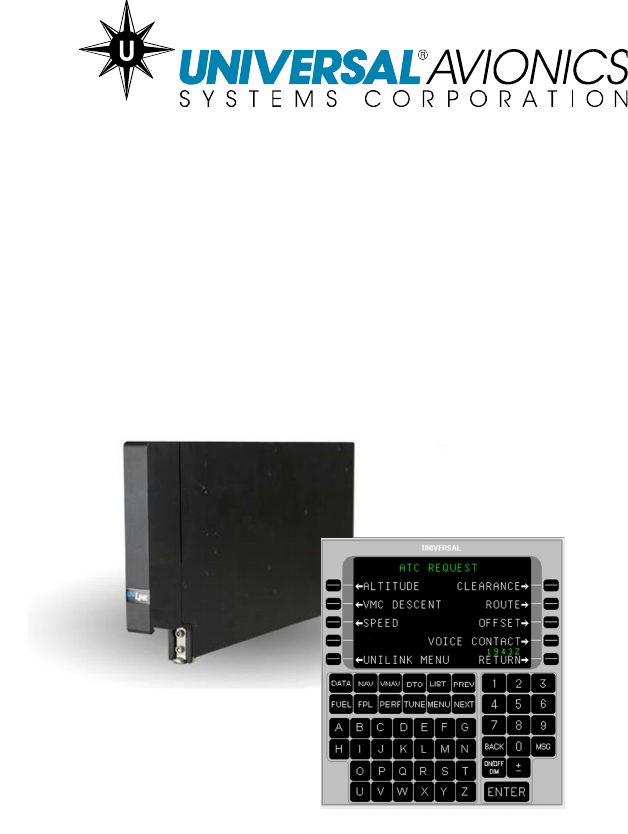
INTRODUCTION
The UniLink Airborne Datalink Product (hereafter referred to as
“UniLink”) is an air-to-ground digital data communication system that
operates with Universal Avionics Systems Corporation’s (UASC’s)
Fight Management Systems (FMSs). It is capable of using a variety of
media such as Satellite Communications (SatCom) and Very High
Frequency (VHF) communications to exchange data with datalink
service providers (DSPs). When communicating over the Aircraft
Communications Addressing and Reporting System (ACARS)
network, UniLink is the functional equivalent of an ARINC 758
Communications Management Unit (CMU). The UL-801 contains an
imbedded VHF data radio (VDR) whereas the UL-800 requires an
external VDR. The VDR provides ACARS and various other types of
network communications capability for UniLink.
The UniLink Future Air Navigation System (FANS) 1/A+
implementation is intended to improve safety of flight, enhance
efficiency, and increase air traffic capacity. Air traffic capacity increase
is promoted by augmenting voice transmissions between crews and
ATC with datalink messages during flight in oceanic and remote areas
that have limited or no radar coverage. The FANS 1/A+
implementation is defined in RTCA/DO-258A and ARINC 622.
Features of this implementation include Air Traffic Services (ATS),
Facilities Notification (AFN), Automatic Dependent Surveillance-
Contract (ADS-C) , and Controller-Pilot Datalink Communications
(CPDLC) text data transmissions.
The FAA has approved the aircraft datalink system to the criteria
contained in AC 20-140A for FANS 1/A+ using VDL M2, VDL M0/A,
and SatCom (IMMARSAT). The datalink system meets the aircraft-
allocated performance requirements of RCP 240 and type 180 (all
sub-networks), and the performance requirements for continental
applications (VDL M2 only). This design approval does not constitute
operational authorization.
NOTE: The colors shown on the screens in this operator’s manual are
based on an FMS with SCN 1000.5/1100.5 installed and
configured for STANDARD-2 color pallet.
UniLink UL-800/801 FANS
SCN 30.X
Operator’s Manual
2 23-20-06.02
December 2011
Components
One UASC FMS utilizing SCN 1000.5/1100.5 or later is required for
UniLink FANS-1/A+ implementation. A complete system includes:
• UASC FMS (SCN 1000.5/1100.5 or later) with a Control
Display Unit (CDU) or Multifunctional Control Display Unit
(MCDU)
• FANS Visual Annunciator(s)
• FANS Aural Alerting device
• Cockpit Voice Recorder (CVR) (to record CPDLC/FANS
messages and events)
• Approved SatCom System (to support remote oceanic FANS
CPDLC communications)
• UniLink Airborne Datalink (SCN 30.X or later) - FANS Enabled
will display the following MAIN MENU:
UniLink UL-800/801 FANS
SCN 30.X
Operator’s Manual
23-20-06.02 3
December 2011
MCDU
Use of a UASC MCDU with the UniLink UL-80X involves the following
configuration/operation performance considerations:
• When configured for a 429 interface, LSKs [L6] and [R6] will
not be functional
• When configured for a 702 interface, LSKs [L5] and [R5] will
not be functional (LSKs [L6] and [R6] will be used instead).
• The plus/minus ( + ) key will not operate as a space key. The
MCDU [SP] key is used for the space function.
UNILINK MENU on MCDU (429 Interface)

UniLink UL-800/801 FANS
SCN 30.X
Operator’s Manual
4 23-20-06.02
December 2011
Applications
FANS 1/A + is principally composed of three applications:
• Controller-Pilot Datalink Communications (CPDLC) –
CPDLC allows datalink messages to substitute for traditional
voice communications for routine communications between a
crew and an air traffic controller. CPDLC messages can be
used to request and grant clearances, to inform the ground of
the aircraft’s position and situation, and to provide instructions
to the crew.
• Air Traffic Services Facilities Notification (AFN) – This
application requires no crew action. AFN allows the aircraft
and an Air Traffic Services (ATS) provider on the ground to
exchange addresses, as well as information about which
FANS applications they support.
•
• Automatic Dependent Surveillance-Contract (ADS-C) –
This application requires no crew action. ADS-C allows ATS
providers to query the aircraft to provide position reports and
other situational data at regular intervals or in response to
events specified by the ATS provider, such as a change in
altitude or lateral deviation.

UniLink UL-800/801 FANS
SCN 30.X
Operator’s Manual
23-20-06.02 5
December 2011
Operations
NOTE: This Operator’s Manual includes procedures and functions
used in a FANS-Enabled UniLink System. Crews that operate
this system must be trained and obtain operational approval
from the state of registry.
Crew interface is accomplished through the FMS CDU and/or MCDU,
utilizing a UASC FMS with SCN 1000.5/1100.5 or later. Data may be
entered at any field highlighted by a cursor. The cursor is displayed in
the first empty data field. Fields with plus signs (+) indicate information
is required. Fields exhibiting minus signs (-) indicate input is optional.
If there is no cursor displayed in a data field, selecting the ENTER key
will place the cursor over the first enterable field on the page. Data is
then entered into the field using the CDU/MCDU alphanumeric keys.
In some situations, flight progress and related data from the FMS will
be prefilled. Subsequent presses of the [ENTER] key will move the
cursor to the next enterable field. Pressing a line select key (LSK)
highlights the corresponding data entry field. Selecting [ENTER] when
the cursor is in the last data field on the page results in the cursor
parking off of the page. Pressing [ENTER] again positions the cursor
on the initial enterable field on the page.
FMS Input
The FMS continuously provides current data to UniLink. Many
messages and requests have fields that prefill with FMS flight
progress data and computed information. In most cases the user
accepts the data for inclusion into the message. It is possible however
to change a value by overriding that value with a manual data entry.
Manual entries are generally retained until power shutdown, although
data that would normally change as a flight progresses will be cleared
once the page has been exited (is no longer displayed).
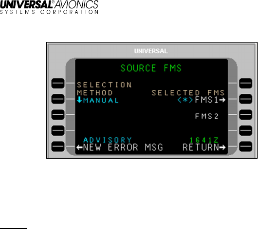
Source FMS
The crew must ensure that the FMS that is navigating the aircraft
(Source FMS) is the same FMS that supplies data to UniLink. The
Source FMS is shown on the SOURCE FMS page, accessed via
MAINTENANCE > SENSOR STATUS > SOURCE FMS.
UniLink UL-800/801 FANS
SCN 30.X
Operator’s Manual
6 23-20-06.02
December 2011
The Source FMS is indicated by an asterisk next to it. Any available
FMS can be manually selected by pressing the adjacent LSK. If
automatic (AUTO) selection is desired, the SELECTION METHOD
LSK will toggle between MANUAL and AUTO.
NOTE: It is important for the crew to ensure that the Source FMS is
not changed prior to an expected flight plan modification
uplink. If the Source FMS is changed prior to the uplink, the
flight plan information will need to be transferred to the new
Source FMS from the previously designated FMS.
Communications
Prior to entering Oceanic Airspace (and loss of VHF communications)
the crew should suspend VHF and transition to satellite
communication (See STATE under VHF DATA in the COMM
CONTROL section).
Current Time
On every UniLink screen above the RETURN option at LSK [5R], the
current UTC time is displayed.
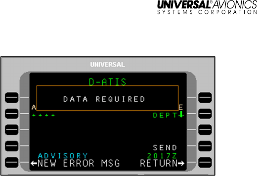
SEND
When the SEND LSK is pressed, the request is placed into queue for
transmission. The delivery status of the message appears above the
SEND option. If data required for the message has not been entered
completely, the SEND option will display as inactive and if selected, a
pop-up window DATA REQUIRED will display (indicating the data is
insufficient).The SEND prompt will not display an arrow (indicating
active) until all required data is entered. Clear the pop-up window by
pressing any active LSK.
UniLink UL-800/801 FANS
SCN 30.X
Operator’s Manual
23-20-06.02 7
December 2011
SEND status displays the current status of the message. When the
SEND LSK is pressed, the status will briefly change to QUEUED, then
SENDING. The selected media for transmission (VHF, SAT, or TEL)
is indicated after SENDING. When acknowledgement is received from
the DSP, SENT status will display.

UniLink UL-800/801 FANS
SCN 30.X
Operator’s Manual
8 23-20-06.02
December 2011
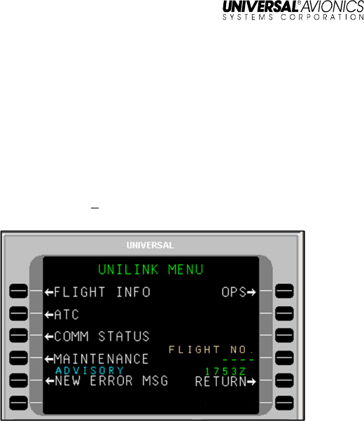
UniLink Advisories
The bottom left LSK on each UniLink page will display either the
UNILINK MENU prompt or UniLink advisories. UniLink advisories
notify the crew of UniLink activity that may require user action. Only
one advisory will display at a time in the order of priority. Pressing the
adjacent LSK allows viewing of the advisory message.
When no advisory is displayed, the advisory field is used to display
the UNILINK MENU prompt. Selecting this prompt displays the
UNILINK MENU.
When on an FMS page, UniLink advisories will be indicated by the
flashing MSG annunciator. Pressing the [MSG] key will allow viewing
of UniLink advisories and messages via the NEW MESSAGE
Advisory prompt (LSK [5L]). This will open the appropriate UniLink
page.
Advisory Messages
NEW ERROR MSG – This advisory is active when an unviewed
message exists in the Error Log. Selection of this advisory displays
the detailed error message page for most recently logged error
message that has not been viewed.
ACKNOWLEDGE – Indicates that an uplink message that is
displayed requires crew acknowledgment. Selection will send an
acknowledgment message.
NEW MSG – Indicates a new unverified message in the Uplink Log.
Selection of this advisory displays the detailed message page for the
latest unread unverified message.
NEW VERIF MSG– Indicates a new verified message in the Uplink
Log. Selection of this advisory displays the detailed message page for
the latest unread verified message.
NEW WX MAP – Indicates a new unviewed weather graphic in the
Graphic Log. Selection of this advisory displays the most recent
graphic.
SELCAL – Indicates a SELCAL request has been received. Selection
of this advisory displays the SELCAL page.
VHF VOICE (applies to UL-800 only) – Indicates the VDR is in Voice
Mode. Selection of this advisory displays the VHF VOICE page.

UniLink UL-800/801 FANS
SCN 30.X
Operator’s Manual
23-20-06.02 9
December 2011
TEL SUSPEND – Indicates the configured dial attempt limit has been
reached and TEL LINK has been suspended (or TEL LINK has been
manually suspended). Selection of this advisory displays the TEL
DATA page.
GND DELAY – Indicates a configurable timer has elapsed since the
last OUT event (push back) and the OFF event (take off) has not yet
occurred. Selection of this advisory displays the EST TIME OFF page.
NOCOMM – Indicates multiple air/ground links are not available.
Selection of this advisory displays the COMM STATUS page.
SAT NOCOMM – Indicates the configured SatCom air/ground link is
not available. Selection of this advisory displays the COMM STATUS
page.
TEL NOCOMM – Indicates the configured airborne telephony
(SatCom) system link is not available. Selection of this advisory
displays the COMM STATUS page.
VHF NOCOMM – Indicates UniLink has determined that a VHF
air/ground link is not available. Selection of this advisory displays the
COMM STATUS page.
NEW ATC MSG – Indicates the presence of an unviewed CPDLC
uplink. Selecting this advisory displays the uplink, together with any
appropriate response options (e.g., WILCO/UNABLE). If multiple
unviewed CPDLC uplinks are present, the oldest will be viewed,
ensuring that messages are presented in the order received. If this
advisory is active when the UNILINK prompt is selected on the FMS
MESSAGE or DATA page, the advisory is selected automatically.
OPEN ATC MSG – Indicates the presence of a CPDLC uplink that
has not yet received a closure response. Required closure responses
include WILCO, UNABLE, ROGER, AFFIRM, and NEGATIVE.
STANDBY is not a closure response and will not dismiss this advisory.
The advisory remains active until the required closure response has
been queued. If multiple open CPDLC uplinks are present, the oldest
will be viewed, ensuring that messages are responded to in the order
received. If this advisory is active when the UNILINK prompt is
selected on the FMS MESSAGE or DATA page, the advisory is
selected automatically.

UniLink UL-800/801 FANS
SCN 30.X
Operator’s Manual
10 23-20-06.02
December 2011
ATC RPT READY – Indicates that the necessary conditions for
sending a CPDLC report downlink previously requested by ATC have
been met. If a single report is ready to be sent, and all the data
required by that report is available, selecting the advisory will display a
review page from which the report may be sent. If a single report is
ready to be sent, and some of the data required by the report must be
entered manually, selecting the advisory will display a message
composition page on which the required data may be entered. If
multiple reports are ready to be sent, selecting the advisory displays
the ATC RPTS page, which contains a log of all ATC report requests
that have not yet been fulfilled. From this page the desired report
request can be selected, and the appropriate review page or message
composition page will be displayed.
Once selected, this advisory is dismissed until another requested
report becomes ready to send. It does not remain active until a report
has been sent.
NOTE: UniLink’s ability to detect REPORT PASSING events is
limited. UniLink can detect the passing of a flight plan
waypoint but cannot detect the passing of an arbitrary pair of
lat/lon coordinates or a given latitude line or meridian. The
pilot retains responsibility for monitoring the situation and
sending requested reports when necessary.
ATC CNCT XXXX – Indicates that a new Air Traffic Service Unit
(ATSU) has become the aircraft’s current ATC data authority. The
ICAO code (XXXX) of the ATSU is included in the advisory. This
advisory is informational; it is dismissed when selected and requires
no further action.
ATC DISCNECT – Indicates that the aircraft no longer has a current
ATC data authority. The connection with the aircraft’s current ATC
data authority has been lost, and there is no next data authority to
take its place. This advisory is informational; it is dismissed when
selected and requires no further action.
ATC LOGON FAIL – Indicates that an attempted AFN log on has
failed, either because a negative acknowledgement was received from
the ATSU or because no acknowledgement was received within ten
minutes of the transmission of the AFN log on downlink. Selecting this
advisory displays the ATC LOG ON page, where the status indication
above the LOG ON prompt at LSK [3L] indicates the reason for the
failure (ERROR or TIMEOUT).

UniLink UL-800/801 FANS
SCN 30.X
Operator’s Manual
23-20-06.02 11
December 2011
ATC RPTS FULL – Indicates that the log of pending CPDLC report
requests received from ATC is now full, and one of these requests
must be either satisfied or deleted. Selecting this advisory displays the
ATC RPTS page. The log of pending report requests can hold up to
fifteen entries.
UniLink UL-800/801 FANS
SCN 30.X
Operator’s Manual
12 23-20-06.02
December 2011
Error Messages
Most error messages generate a NEW ERROR MSG advisory which
is displayed in the ERROR LOG pages. Certain error messages which
are considered more urgent are displayed in a pop-up window in the
middle of the current UniLink page, for example: QUEUE FULL,
DISPLAY PROCESSOR FAIL, or A740: PRINTER FAIL.
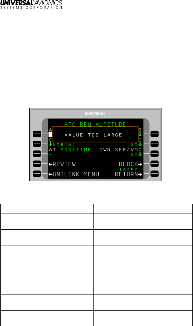
Entry Error Pop-up Windows
UniLink provides feedback when an invalid entry is made. After an
invalid entry, a pop-up window identifies the entry error.
The following is a list of data entry errors and the condition that will
initiate the error pop-up window.
Screen Text Condition
VALUE TOO LARGE The entered numeric value
exceeds the allowable maximum.
VALUE TOO SMALL The entered numeric value is less
than the allowable minimum.
TOO MANY CHARACTERS The entered number of characters
exceeds the allowable maximum.
TOO FEW CHARACTERS The entered number of characters
is less than the allowable
minimum.
VALUE MUST BE NUMERIC The prompt only accepts digits.
VALUE MUST BE
ALPHABETIC The prompt only accepts letters.
TOO MUCH PRECISION The entered numeric value has
too many numbers to the right of

UniLink UL-800/801 FANS
SCN 30.X
Operator’s Manual
23-20-06.02 13
December 2011
Screen Text Condition
the decimal point.
NEGATIVE NOT PERMITTED The prompt only accepts positive
numbers.
MISSING N OR S The entered latitude does not
specify a hemisphere.
MISSING E OR W The entered longitude does not
specify a hemisphere.
INVALID NUMBER The entered characters could not
be interpreted as a number.
INVALID ENTRY The entered characters do not
conform to specific textual data
item input restrictions.
ILLEGAL HYPHEN The entered tail number begins or
ends with a hyphen.
ILLEGAL VHF FREQUENCY The entered frequency is not a
valid VHF Voice or data
frequency, or is the CSC
frequency (136.975).
ILLEGAL DATA FREQUENCY The Emergency Voice frequency
(121.500) has been entered at a
prompt that expects to receive a
data frequency.
PRESSURE OUT OF RANGE The entered atmospheric
pressure is out of range.
INVALID SECONDS VALUE The entered seconds value within
a time field is invalid.
INVALID MINUTES VALUE The entered minutes value within
a time field is invalid.
INVALID HOURS VALUE The entered hours value within a
time field is invalid.
INVALID DAY The entered day value within a
date field is invalid.
INVALID MONTH The entered month value within a
date field is invalid.
INVALID YEAR The entered year value within a

UniLink UL-800/801 FANS
SCN 30.X
Operator’s Manual
14 23-20-06.02
December 2011
Screen Text Condition
date field is invalid.
INVALID LEAP YEAR The entered date value includes
Feb 29
th
in a year that is not a
leap year.
INVALID SECONDS The entered seconds value within
a latitude or longitude field is
invalid.
INVALID MINUTES The entered minutes value within
a latitude or longitude field is
invalid.
DATA CANNOT BE MODIFIED ( MCDU only) An attempt has
been made to delete data from an
edit prompt that displays read-
only data.
TOO MANY VALUES MCDU only) Too may slashes
have been entered in the
scratchpad; the number of
entered values exceeds the
number of values associated with
an LSK.
INTERNAL ERROR An error is detected in the
software or customer database.
ENTER L OR R, THEN
DISTANCE The entered CPDLC offset value
did not begin with L or R.
DATA REQUIRED An attempt has been made to
navigate to a new page or send a
request without supplying
required information.

UniLink UL-800/801 FANS
SCN 30.X
Operator’s Manual
23-20-06.02 15
December 2011
Alerting
Message Alerting
Message alerting functions include visual and aural alerts, and digital
outputs to various Line-Replaceable Units (LRU). The outputs are
intended to drive visual or aural alerting when a new uplink message
is received. The digital outputs provide messaging alerts that may be
used by other devices for additional alerting functions, such as the
FMS MSG annunciator.
Alert Inhibiting
UniLink Alert Inhibiting operates in order to suspend the output of
message alerting during critical phases of flight (i.e., takeoff and
landing). Displayed UniLink advisories are not suppressed during
critical flight phases.
NOTE: If UniLink transitions out of the takeoff phase due to
transitioning directly into the landing phase, UniLink will
continuously inhibit alert outputs. This ensures there are no
aural alerts that could potentially distract the crew.
UniLink UL-800/801 FANS
SCN 30.X
Operator’s Manual
16 23-20-06.02
December 2011
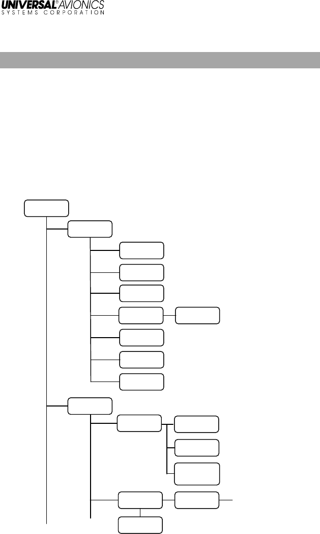
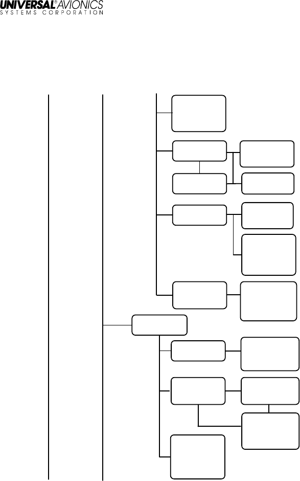
User Interface Menu Tree
The UniLink Main Menu page is accessed from the UNILINK prompt
on either DATA 1/4 or the MESSAGE page (from a reboot or initial
startup). To navigate down through the menu tree, select the
applicable page option LSKs to move to the desired function. Use the
RETURN LSK to move back up the menu tree.
Pages shown in the menu trees may or may not be available
depending on specific installation configuration. Check with installer
for specific configuration details.
UniLink Menu (SCN 30.X)
UNILINK
MENU
D-ATIS
TWIP
DEPARTURE
CLX
OCEANIC
CLX
OCEANIC
CLX ATC
VERIFY
MSGS
PUSHBACK
CLX
EXP TAXI CLX
ATC
EMERGENCY
ATC LOG ON
2/2
ATC LOG ON
1/2
ATC REVIEW
(PAN)
ATC REVIEW
(MAYDAY)
ATC
FLIGHT INFO
ATC REVIEW
(Cancel
Emergency)
ATC LOG ON
TO
(LOG ON TO Region
pages including:
- N PACIFIC
- S PACIFIC
- ASIA
- INDIAN OCEAN
- N ATLANTIC
- S ATLANTIC
- EUROPE)
(Continued on next page)
UniLink UL-800/801 FANS
SCN 30.X
Operator’s Manual
23-20-06.02 17
December 2011
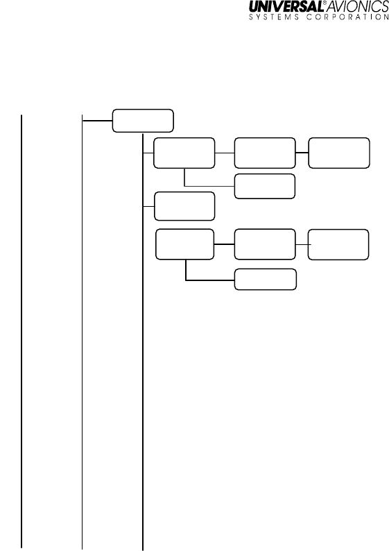
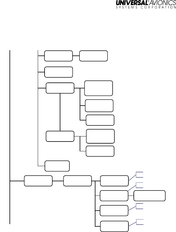
UniLink Menu (continued)
UNILINK
MENU
Continued
ATC
REQUEST
ATC REVIEW
(REQUEST VMC
DESCENT)
ATC REQ
ALTITUDE
(SINGLE)
ATC REQ
ALTITUDE
(BLOCK)
ATC REQ
SPEED
(SINGLE)
ATC REQ
SPEED
(BLOCK)
ATC REVIEW
ATC
Continued
ATC REVIEW
(REQUEST)
ATC REVIEW
ATC REVIEW
(REQUEST
BLOCK)
(Continued on next page)
UniLink UL-800/801 FANS
SCN 30.X
Operator’s Manual
18 23-20-06.02
December 2011
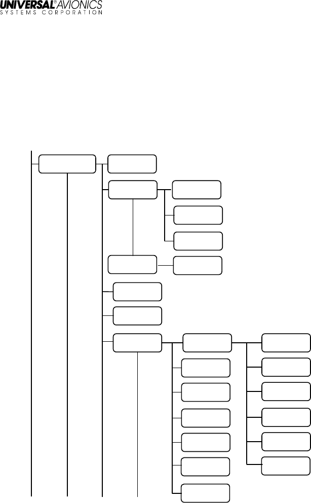
UniLink Menu (continued)
UNILINK
MENU
Continued
ATC
Continued
ATC REVIEW
ATC REQ RTE
1/2
ATC
REQUEST
CLEARANCE
(FREE TEXT)
ATC EXP
ALTITUDE
ATC REVIEW
(REQUEST
OFFSET OF
ROUTE FREE-
TEXT)
ATC REQ
OFFSET
ATC
REQUEST
AT
ATC EXPECT
WHEN CAN WE
ATC REVIEW
(REQUEST VOICE
CONTACT FREE-
TEXT)
ATC REVIEW
(WHEN CAN WE
EXPECT FREE-
TEXT)
ATC EXP
SPEED (BLOCK)
ATC REVIEW
(WHEN CAN WE
EXPECT BACK
ON ROUTE
FREE-TEXT)
ATC
REQUEST
Continued
ATC REQ RTE
2/2
ATC
REQUEST
DTO
ATC REQ
VOICE
CONTACT
ATC EXP
SPEED
(SINGLE)
ATC REVIEW
(WHEN CAN WE
EXPECT FREE-
TEXT)
(Continued on next page)
UniLink UL-800/801 FANS
SCN 30.X
Operator’s Manual
23-20-06.02 19
December 2011
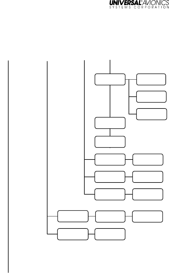
UniLink Menu (continued)
ATC RPTS 1/X
ATC FREE-
TEXT ATC REVIEW
ATC POS RPT
1/2
ATC
REPORTED
WPT
ATC MSGS
1/X
UNILINK
MENU
Continued
ATC
Continued
ATC NEXT
WPT
ATC REVIEW
COMM
STATUS
COMM
CONTROL
VHF DATA
VHF VOICE
SAT DATA
TEL DATA
FREQUENCIES
ATC POS RPT
2/2
ATC
ENSUING
WPT
ATC REVIEW
See NOTE 1
See NOTE 1
See NOTE 2
See NOTE 3
NOTES
:
1. Only available if VHF is enabled in configuration (UL-800 only)
2. Only available if SAT is enabled in configuration.
3. Only available if TEL is enabled in configuration.
(Continued on next page)
UniLink UL-800/801 FANS
SCN 30.X
Operator’s Manual
20 23-20-06.02
December 2011
Maintenance Menu
Maintenance provide access UniLink maintenance-related functions.
They are accessed by pressing MAINTENANCE, LSK [4L] on the
UNILINK MENU page. Other than TESTS, there are no user-related
functions on these pages. See the associated UniLink Installation
Manual for installation and maintenance procedures.
BCST DATA
SOURCE FMS
VERSIONS
ERROR LOG
SENSORS 1/2 DISCRETES
MAINTENANCE
1/3 DEVICES
UNILINK
MENU
Continued
GRAPHICS
DISC IN
DISC OUT
ARINC RX
ARINC TX
SERIAL
SYS CONFIG
1/4
POS REPORT
VHF CONFIG
SAT CONFIG
PRIORITY
TEL CONFIG
REVIEW
SENSORS 2/2 VDR STATUS
I/O CONFIG
(Continued on next page)
UniLink UL-800/801 FANS
SCN 30.X
Operator’s Manual
23-20-06.02 21
December 2011
Maintenance Menu (Continued)
UNILINK
MENU
Continued
FANS FPL
DATA
MAINTENCE
Continued
MAINTENCE
1/3
Continued
TESTS TESTS
POWER LOG POWER LOG
PRINT JOB PRINT JOBS
MAINTENANCE
3/3
AIRCRAFT
CLEARANCES
ALERTS
SYS CONFIG
4/4
SYS CONFIG
3/4
SYS CONFIG
2/4
SYS
CONFIG
Continued
DATA LOAD
2/2
DATA LOAD
1/2
MAINTENANCE
2/3
(Continued on next page)
UniLink UL-800/801 FANS
SCN 30.X
Operator’s Manual
22 23-20-06.02
December 2011
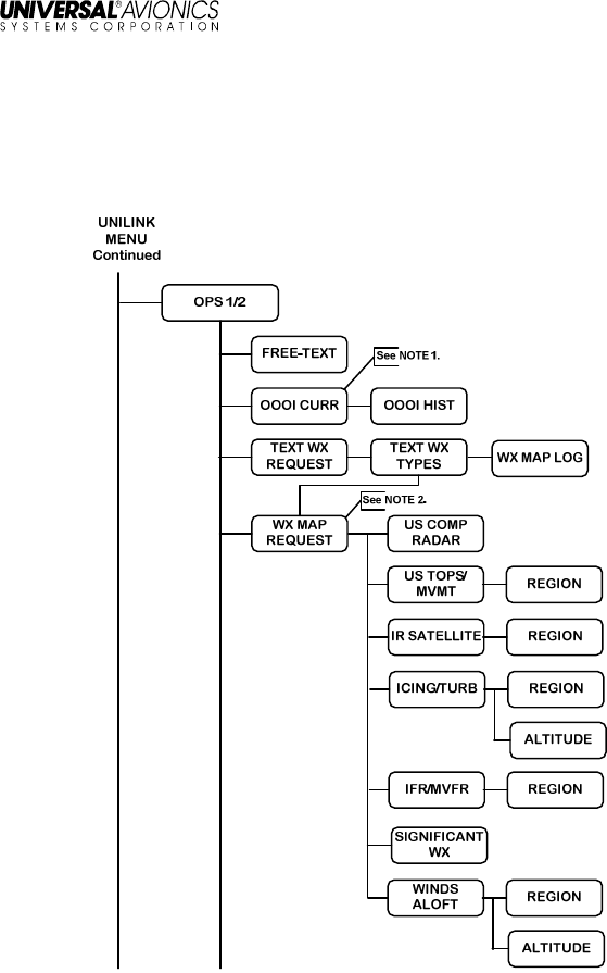
OPS Menu
Operational (OPS) pages are used to access UniLink AOC-related
functions. They are accessed through the UniLink Menu page by
selecting OPS, LSK [1R}.
NOTES
:
1. Only available if OOOI is enabled in configuration
2. Only available if TEL is enabled in configuration.
(Continued on next page)
UniLink UL-800/801 FANS
SCN 30.X
Operator’s Manual
23-20-06.02 23
December 2011
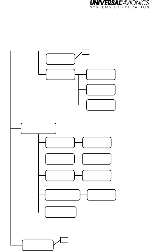
OPS Menu (Continued)
WX MAP LOG
OPS MSGS
MESSAGE
LOGS VERIF MSGS
UNILINK
MENU
Continued
OPS 2/2
OPS 1/2
Continued
DELAY
SITUATION
REASON
SITUATION
POS REPORT
DELAY
REASON
DIVERT
REASON
ETA REASON
WX MAP LOG
SELCAL
ETA UPDATE
DIVERSION
See NOTE 1.
See NOTE 2.
NOTES
:
1. Only available if TEL is enabled in configuration
2. The SELCAL option only displays when associated
messages are available. Check with DSP for availability of
this feature.
UniLink UL-800/801 FANS
SCN 30.X
Operator’s Manual
24 23-20-06.02
December 2011
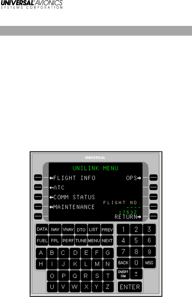
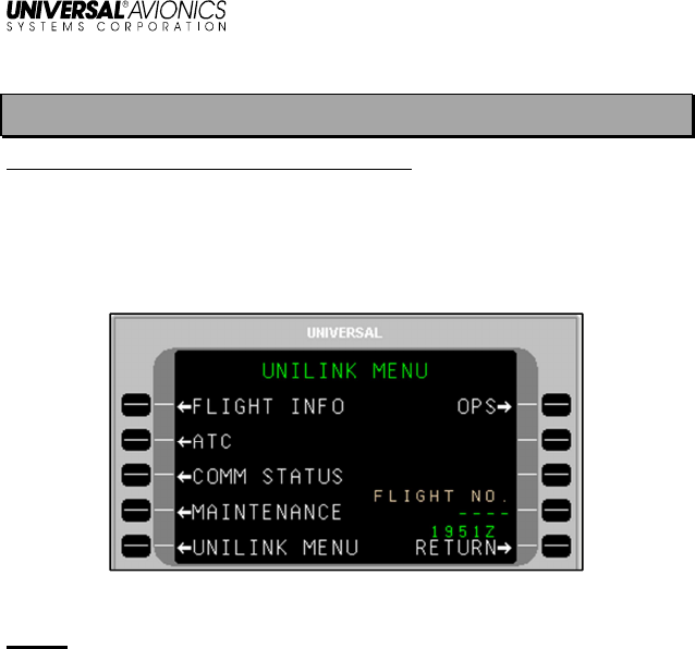
UNILINK MENU
Menu Navigation: [DATA] or [MSG] > UNILINK
All UNILINK MENU options are contained on one page.
The UniLink Menu page is accessed by selecting UNILINK from either
the FMS DATA 1/4 page or the FMS MESSAGE 1/1 page.
NOTE: Based on installation and configuration, the FLIGHT NO. field
may or may not be displayed.
UniLink UL-800/801 FANS
SCN 30.X
Operator’s Manual
23-20-06.02 25
December 2011
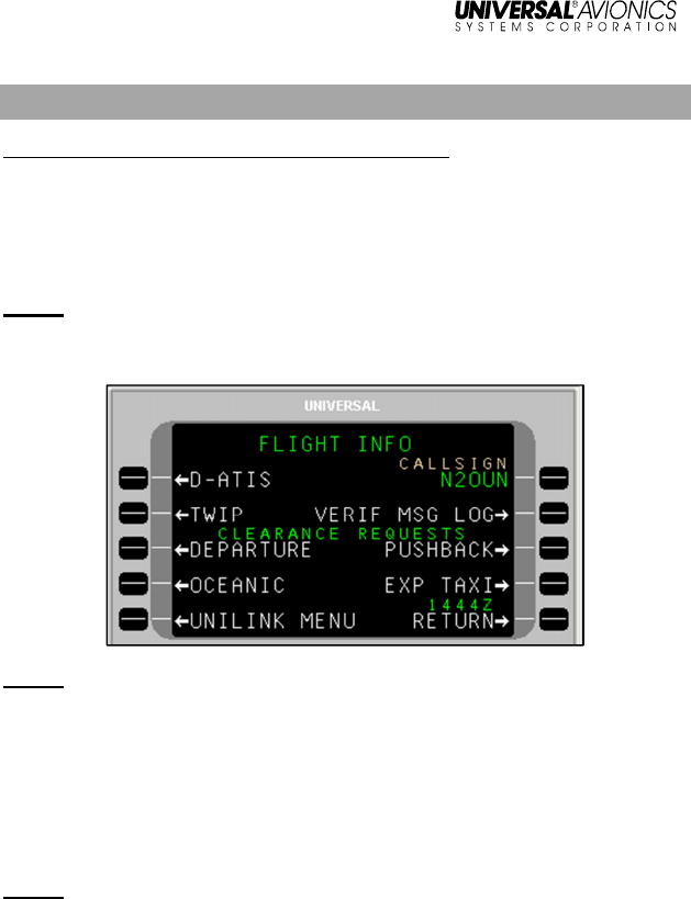
Flight Information
Menu Navigation: UNILINK MENU > FLIGHT INFO
On the UNILINK MENU page, press FLIGHT INFO, LSK [1L], to
access the FLIGHT INFO page. All services provided on this menu
are available only over the ACARS VHF or SatCom packet data
network.
NOTE: Flight Information Services are advisory only. It is the
responsibility of the crew to exercise reasonable and prudent
judgment in the use of these advisory services.
NOTE: DEPARTURE, OCEANIC, PUSHBACK, and EXP TAXI
requests are configurable options and are not displayed if
configured as disabled.
The aircraft tail number, or registration (entered during configuration),
is automatically inserted in the CALL SIGN field (less any hyphen
characters). If the aircraft has a different ATS call sign (flight identifier)
assigned for the flight, it should be manually entered.
NOTE: If the flight number option is enabled in configuration and a
flight number is entered on the UNILINK MENU page, the
three-digit airline ID and four-digit flight number (e.g.,
UVA1234) is inserted in the CALLSIGN field, overriding the
tail number.
To manually enter a callsign:
1. Press LSK [1R]. The CALLSIGN field will become active.
3. Enter the desired callsign using the alphanumeric keys.
4. Press [ENTER]. The new callsign will display in the field.

UniLink UL-800/801 FANS
SCN 30.X
Operator’s Manual
26 23-20-06.02
December 2011
NOTE: The hierarchy of flight identifier information is as follows (with
1 being the highest):
1. A manually entered call sign
2. Airline ID/Flight Number (commercial airline only)
3. Default registration (set during installation/configuration)
UniLink UL-800/801 FANS
SCN 30.X
Operator’s Manual
23-20-06.02 27
December 2011
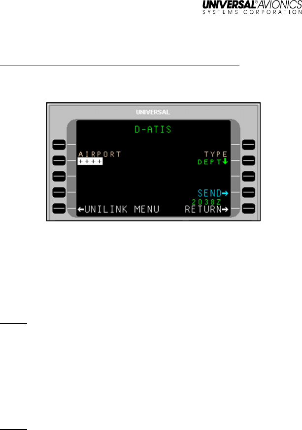
D-ATIS Request
Menu Navigation: UNILINK MENU > FLIGHT INFO > D-ATIS
The D-ATIS page is used to request local arrival or departure
Automatic Terminal Information Service (ATIS).
To request ATIS:
1. Press D-ATIS, LSK [1L] on the FLIGHT INFO page. The D-ATIS
page will display.
2. With AIRPORT active, enter the Airport Identifier and press
[ENTER] or accept the default destination airport from the FMS
flight plan.
NOTE: If an incomplete airport identifier is entered, the pop-up
window TOO FEW CHARACTERS will display and the field
will flash. Pressing the LSK and re-entering a complete
identifier will correct the error.
3. DEPT is the default type of ATIS. Press LSK [2R] to toggle this
field between ARRV and DEPT as needed.
4. Press SEND, LSK [4R] to place the message in queue for
transmission.
NOTE: If the information on this page is incomplete, the pop-up
window DATA REQUIRED will display and the SEND prompt
will not enable.
UniLink UL-800/801 FANS
SCN 30.X
Operator’s Manual
28 23-20-06.02
December 2011
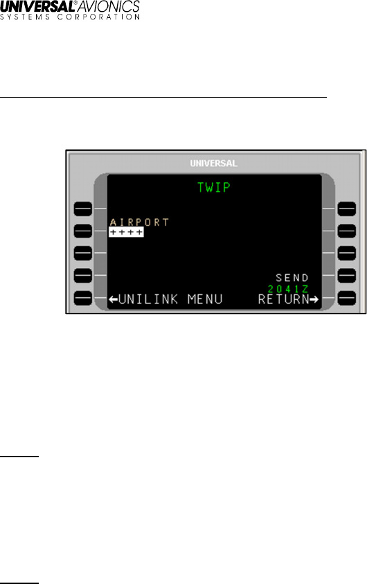
TWIP Request
Menu Navigation: UNILINK MENU > FLIGHT INFO > TWIP
The TWIP page is used to request Terminal Weather Information for
Pilots (TWIP).
To make a TWIP request:
1. Press TWIP, LSK [2L] on the FLIGHT INFO page. The TWIP
page will display.
2. With AIRPORT active, enter a destination airport and press
[ENTER] or accept the Destination Airport from the FMS flight
plan.
NOTE: If an incomplete airport identifier is entered, the pop-up
window TOO FEW CHARACTERS will display and the field
will flash. Pressing the LSK and re-entering a complete
identifier will correct the error.
3. Press the SEND LSK to place this message in queue for
transmission. The SEND prompt will not be enabled if the
information on this page is incomplete.
NOTE: If the information on this page is incomplete, the pop-up
window DATA REQUIRED will display and the SEND prompt
will not enable.
UniLink UL-800/801 FANS
SCN 30.X
Operator’s Manual
23-20-06.02 29
December 2011
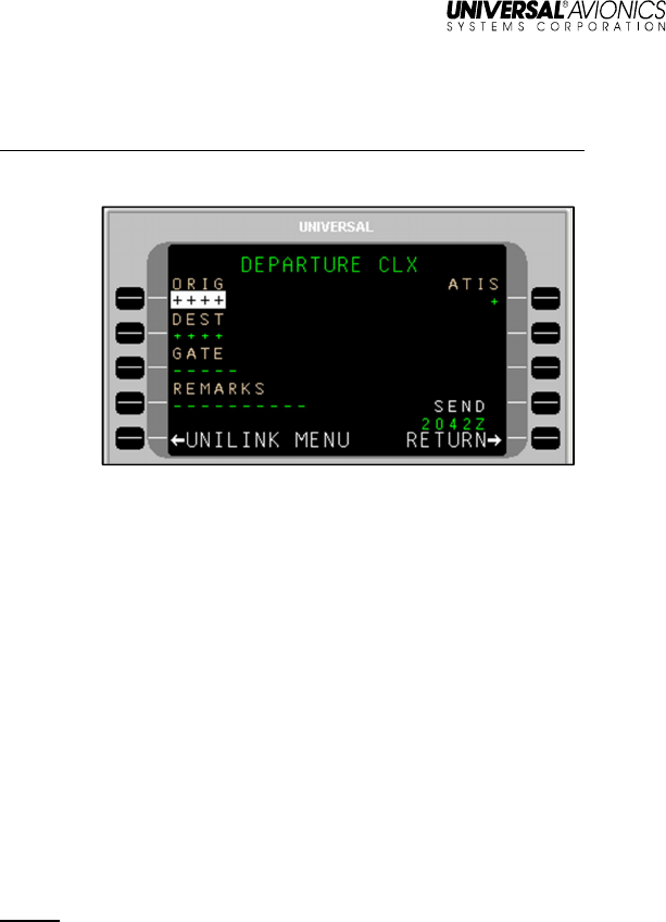
Departure Clearance Request
Menu Navigation: UNILINK MENU > FLIGHT INFO > DEPARTURE
The DEPARTURE CLX page is used to request departure clearance.
To request a Departure Clearance:
1. Press Departure, LSK [3L] on the FLIGHT INFO page. The
DEPARTURE CLX page will display.
2. Verify or change the ORIG (origination) airport. This field defaults
to the departure airport identifier from the FMS.
3. Verify or change the DEST (destination) airport. This field
defaults to the destination airport from the FMS.
4. Enter GATE number (optional).
5. Press the REMARKS LSK to enter any remarks as needed (see
the REMARKS Section in this manual).
6. Enter the latest ATIS version (alpha character).
7. Press SEND, LSK [4R] to place this message in queue for
transmission.
NOTE: The SEND prompt will not be enabled if the required
information on this page is incomplete, the call sign from the
Flight Information Services page is not entered, or the aircraft
type has not been configured from the Aircraft Configuration
page. Any attempt to send this page with incomplete
information results in the pop-up window DATA REQUIRED
displaying.
UniLink UL-800/801 FANS
SCN 30.X
Operator’s Manual
30 23-20-06.02
December 2011
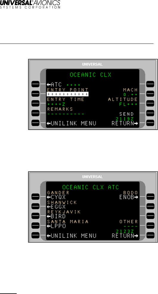
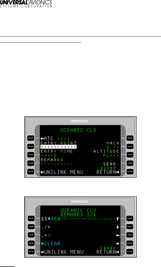
Oceanic Clearance Request
Menu Navigation: UNIILINK MENU > FLIGHT INFO > OCEANIC
The OCEANIC CLX page is used to request Oceanic Clearance.
To request an Oceanic Clearance:
1. Press OCEANIC, LSK [4L] on the FLIGHT INFO page. The
OCEANIX CLX page will display.
2. Press ATC, LSK [1L] to open the OCEANIX CLX ATC page.
3. Select the ATC Station using the adjacent LSK, or enter a station
ID in the OTHER field, LSK [R4]. The OCEANIX CLX page will
display, showing the selected ATC station.
4. If not active, press the ENTRY POINT, LSK [2L] and enter the
point of entry into oceanic airspace. Press [ENTER].
NOTE: Enter three to eleven characters to specify the position by
latitude/longitude or by waypoint identifier.
5. If not active, press the ENTRY TIME, LSK [3L] and enter the
requested time for the clearance. Press [ENTER].

UniLink UL-800/801 FANS
SCN 30.X
Operator’s Manual
23-20-06.02 31
December 2011
6. If not active, press MACH, LSK [2R] and enter the requested
Mach number. Press [ENTER].
7. If not active, press ALTITUDE, LSK [3R] and enter the requested
flight level. Press [ENTER].
8. Press the REMARKS LSK and enter any remarks as needed.
OCEANIC Clearance remarks are entered using the OCEANIC
CLX REMARKS page (see the REMARKS Page section in this
manual).
9. Press SEND to place the message in queue for transmission.
NOTE: If the information on this page is incomplete, the pop-up
window DATA REQUIRED will display and the SEND prompt
will not enable.
Verified Message Log
Menu Navigation: UNILINK MENU > FLIGHT INFO > VERIF MSG LOG
The VERIF MSGS page displays all verified uplink and downlink
messages and can be used to check the queue status of sent
messages. See VERIF MSG LOG in the MESSAGE LOGS section of
this manual.
UniLink UL-800/801 FANS
SCN 30.X
Operator’s Manual
32 23-20-06.02
December 2011
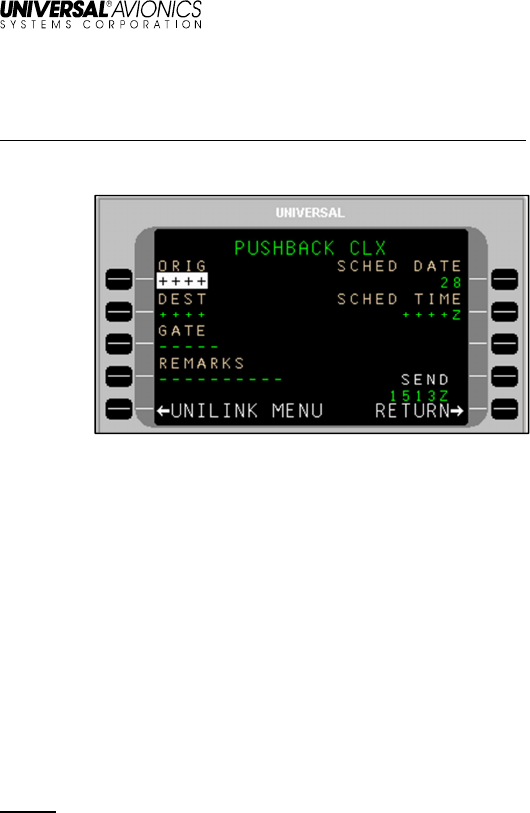
Pushback Clearance Request
Menu Navigation: UNILINK MENU > FLIGHT INFO > PUSHBACK
The PUSHBACK CLX page is used to request pushback clearance.
To request Pushback Clearance:
1. Press PUSHBACK, LSK [3R] on the FLIGHT INFO page. The
PUSHBACK CLX page will display.
2. Verify the ORIG (Origination) airport. Change by pressing the
ORIG field LSK (if not active) and entering a different airport.
Press [ENTER].
3. If not active, press DEST (Destination), LSK [2L] to enter the
destination airport. Press [ENTER].
4. If not active, press GATE, LSK [3L] to enter gate Information
(optional). Press [ENTER].
5. If not active, press SCHED DATE, LSK [1R] to enter the
scheduled date (day). Press [ENTER].
NOTE: Default date is per GMT.
6. If not active, press SCHED TIME, LSK [2R] to enter the
scheduled time. Press [ENTER].
7. Press REMARKS, LSK [4L] to enter any remarks as needed
(optional). Pushback remarks are entered using the PUSHBACK
CLX REMARKS page (See the Remarks Page section in this
manual).
8. Press SEND, LSK [4R] to place the message in queue for
transmission.
UniLink UL-800/801 FANS
SCN 30.X
Operator’s Manual
23-20-06.02 33
December 2011
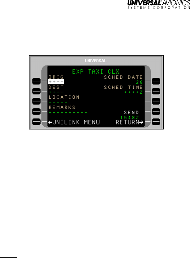
Expected Taxi Clearance Request
Menu Navigation: UNILINK MENU > FLIGHT INFO > EXP TAXI
The EXP TAXI CLX is used to request an Expected Taxi Clearance.
To request an Expected Taxi Clearance:
1. Press EXP TAXI, LSK [4R] on the FLIGHT INFO page. The EXP
TAXI CLX page will display.
2. Verify the ORIG (Origination) airport. Change by pressing the
ORIG field LSK (if not active) and entering a different airport.
Press [ENTER].
3. If not active, press DEST (Destination), LSK [2L] to enter the
destination airport. Press [ENTER].
4. If not active, press GATE, LSK [3L] to enter gate Information
(optional). Press [ENTER].
5. If not active, press SCHED DATE, LSK [1R] to enter the
scheduled date (day). Press [ENTER].
NOTE: Default date is per GMT.
6. If not active, press SCHED TIME, LSK [2R] to enter the scheduled
time. Press [ENTER].
7. Press REMARKS, LSK [4L] to enter any remarks as needed
(optional). Taxi Clearance remarks are entered using the EXP
TAXI CLX REMARKS page (See the Remarks Page section in
this manual).
8. Press SEND to place the message in queue for transmission.
UniLink UL-800/801 FANS
SCN 30.X
Operator’s Manual
34 23-20-06.02
December 2011
Remarks – Create and Include with Requests
Menu Navigation: UNILINK MENU > FLIGHT INFO > DEPARTURE or
OCEANIC or PUSHBACK or EXP TAXI
The Remarks page is available from the following Flight Information
(FLIGHT INFO) services pages:
• DEPARTURE
• OCEANIC
• PUSHBACK
• EXP TAXI
To access the REMARKS Page:
1. On a Flight Information service page (in this example, OCEANIC
CLX), press the REMARKS LSK.
The associated Remarks page will open with the cursor (@) flashing
on the text line.
NOTE: In this example, OCEANIC CLX is used. All REMARKS pages
are operated in the same manner.

UniLink UL-800/801 FANS
SCN 30.X
Operator’s Manual
23-20-06.02 35
December 2011
2. Create a message using the alphanumeric keys and LSKs.
• The [ + ] key inserts spaces in the text ([SP] key on MCDU).
Text will automatically word wrap to the next line as applicable.
The number of pages in the message will increase as
necessary to accommodate entered text.
• LSKs [1L] through [3L] provide special characters as indicated
on the display. Pressing the specific LSK multiple times cycles
through the displayed choices. To enter a special character
several times in a row, select another key between special
character LSK presses (example: to enter several periods in a
row, press LSK [2L], then the right-arrow key (which does
nothing), then [2R], then the right-arrow key, etc.).
• The arrow LSKs ([1R] through [4R]) move the cursor position
within text already entered. Text entered at the cursor position
in front of other text is inserted and word wrapping will occur as
necessary.
• To start a new line of text, press [ENTER]; the cursor will start
a new line of text (the active text line will have larger text).
• The CLEAR LSK erases all entered text on the page.
3. When finished editing the text portion of the message, press
RETURN, LSK [5R]. The entered text will display in the
REMARKS field for review.
NOTE: The REMARKS field displays the first 7 characters of entered
text. A following ellipsis (…) indicates there is more text in the
message. The REMARKS page allows review of the entire
remarks text.
4. Press the SEND LSK to place the message in queue for
transmission.
UniLink UL-800/801 FANS
SCN 30.X
Operator’s Manual
36 23-20-06.02
December 2011
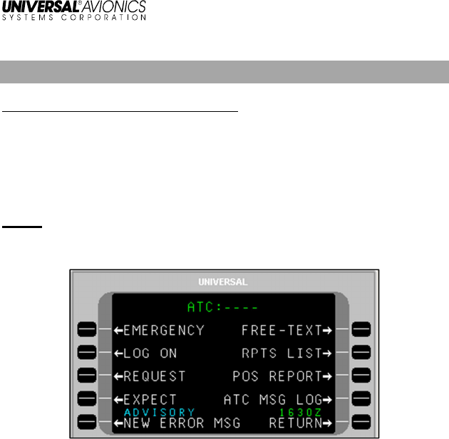
ATC
Menu Navigation: UNILINK MENU > ATC
The ATC page provides a number of options for communicating with
Air Traffic Control. Options to communicate emergencies, various
reports, requests, and general commentary are available on this page.
To access the ATC page, press ATC, LSK [2L] on the UNILINK
MENU page.
NOTE: If connected to a Current Data Authority (CDA), it will display
in the page title. Otherwise dashed lines will display.
UniLink UL-800/801 FANS
SCN 30.X
Operator’s Manual
23-20-06.02 37
December 2011
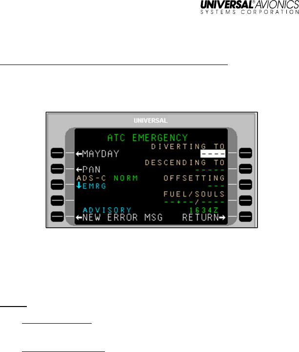
EMERGENCY
Menu Navigation: UNILINK MENU > ATC > EMERGENCY
The ATC EMERGENCY page displays emergency communication
and messaging options. Selecting EMERGENCY, LSK [1L} opens the
ATC EMERGENCY page.
Create and Send an Emergency Message
To send an emergency message:
1. Verify that fields for LSKs [R1] through [R4} (DIVERTING TO,
DESCENDING TO, OFFSETTING, FUEL/SOULS) are correct.
NOTE: All these fields are optional.
DIVERTING TO – A four character airport identifier indicating the
diversion destination.
DESCENDING TO – Altitude the aircraft will descend to using
the following entry criteria:
• Flight Level – Enter the three digit designation for flight
level (370 = FL370), “FL” followed by a three digit number
• Altitude (feet) – Enter the altitude (i.e., 16000)
• Altitude Below 600 ft. – Enter the altitude with a leading 0
(0137 = 137 ft)
• Metric Flight Level – Enter S followed by a number
• Altitude (meters) – Enter a number followed by an “M”

UniLink UL-800/801 FANS
SCN 30.X
Operator’s Manual
38 23-20-06.02
December 2011
Altitude Data Ranges
Units
Lower Limit
Upper Limit
Resolution
Feet 0 25,000 10
Meters 0 16,000 1
Flight Level 030 600 1 (i.e., 100 ft.)
Metric Flight
Level 0100 2000 1 (i.e., 10m.)
OFFSETTING – The offset distance from the original flight plan
track the aircraft will acquire using the following criteria:
• Entered distance must be preceded by an “L” or “R” as
applicable
• Offset distance must be between 1 and 128 NM, per RTCA
DO-258A. UniLink allows communication of an offset up to
128 NM; however, the UASC FMS will only accept a
maximum of 99.9 NM. A full offset distance greater than
99.9 NM will require manual steering by the crew.
FUEL/SOULS – Indicate the flight time in hours + minutes
(XX+XX) that the remaining fuel makes available (maximum
entry of 23+59), and the number of persons onboard.
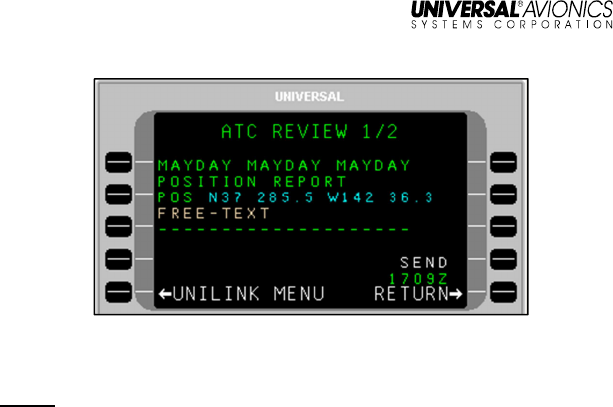
2. Press the MAYDAY or PAN LSK as needed. The associated
ATC REVIEW page will display. Depending on how much
information was pre-filled or entered into the right-hand fields on
the ATC EMERGENCY page, the ATC REVIEW page will have
multiple pages.
NOTE: For a Mayday downlink, an abbreviated position report
including current position, time, altitude, and speed will display
on the ATC REVIEW page (if available from the source air
data computer (ADC) or the FMS).
NOTE: The SEND option will not be available for sending the
message until all pages in the ATC REVIEW have been
viewed.
UniLink UL-800/801 FANS
SCN 30.X
Operator’s Manual
23-20-06.02 39
December 2011
3. As needed, press the FREE-TEXT, LSK [3L] and enter
information as required. Press the [ENTER] key.
NOTE: The FREE-TEXT field is optional. It can contain a maximum of
24 characters.
4. Press the SEND LSK. QUEUED will display above the SEND
option to indicate the message is in queue for transmission. The
SEND option will no longer have an arrow.
5. Press the RETURN LSK to display the ATC EMERGENCY page.
UniLink UL-800/801 FANS
SCN 30.X
Operator’s Manual
40 23-20-06.02
December 2011
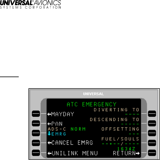
Cancel an Emergency
To cancel an emergency:
1. On the ATC EMERGENCY page, press CANCEL EMRG, LSK
[4L]. The ATC REVIEW (CANCEL EMERGENCY) page will
display.
NOTE: The CANCEL EMRG prompt becomes visible only after
sending a MAYDAY downlink.
2. Press the FREE-TEXT LSK and enter information as needed.
3. Press the SEND LSK to place the message is in queue for
transmission.
UniLink UL-800/801 FANS
SCN 30.X
Operator’s Manual
23-20-06.02 41
December 2011
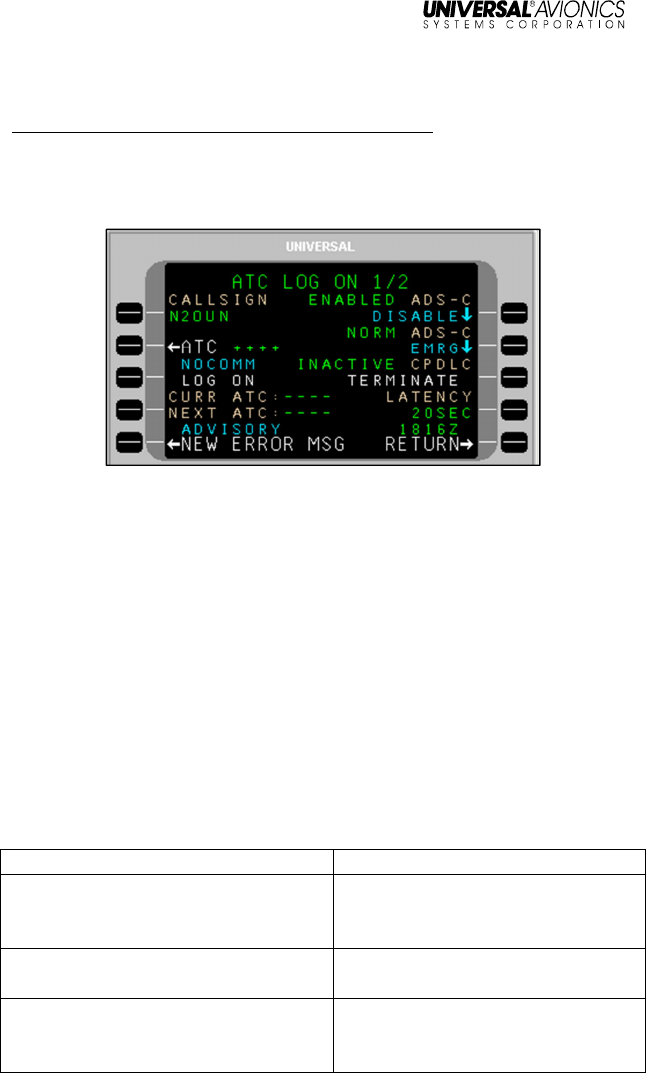
LOG ON
Menu Navigation: UNILINK MENU > ATC > LOG ON
The ATC LOG ON page is used to log on to an ATC facility via the
ATS Facilities Notification (AFN) application. This log-on functions as
a datalink equivalent to voice initial contact.
Prior to initiating an ATC Log On, the following should be verified:
• The aircraft identification matches the identification in the filed
flight plan
• The flight plan contains the correct aircraft registration and
address
• (If planning to use ADS-C services), ADS-C is ENABLED
• Prior to ATC LOG ON, and throughout FANS operations, the
crew should ensure the flight path intent data (waypoint
Lat/Long, altitude, and offsets) of the Universal Avionics FMS
providing data to the UL-80X remains synchronized to the
navigating FMS by automatic or manual means for at least the
next two waypoints.
Appropriate times and conditions for performing an ATC log on
include:
Time/Condition ATSU/ATC
Prior to takeoff (where permitted or
required), but no earlier than 45
minutes prior to ETD
Current ATSU for the FIR that the
departure airport is located within.
15 minutes or more prior to FIR
boundary estimate, above 10,000 feet
Current ATSU for the FIR in which
the aircraft is operating
Less than 15 minutes prior to FIR
boundary estimate, above 10,000 feet
Next ATSU that provides CPDLC
and/or ADS-C services for the FIR
on that flight
UniLink UL-800/801 FANS
SCN 30.X
Operator’s Manual
42 23-20-06.02
December 2011
Following an unsuccessful data link
transfer to another ATSU or when
instructed by ATC
As instructed per above
LOG ON
To perform an AFN log on:
1. Verify the aircraft identification. Or press CALLSIGN, LSK [1L],
enter an aircraft call sign, and press [ENTER].
2. Press ATC, LSK [2L] to select an ATC facility. The ATC LOG ON
TO page will open for selection of a region. A region selection
opens listings of specific ATC facility identifiers. A facility ID may
also be manually entered. Selecting an ATC facility returns the
display to ATC LOG ON 1/2.
3. Once an ATC facility is selected, the LOG ON option becomes
active (arrow displays). Press LOG ON, LSK [3L] to initiate an
AFN log on downlink message.
NOTE: A successful AFN log on is indicated by SUCCESS displaying
above the LOG ON option. The ATC facility may in turn initiate
ADS-C and/or CPDLC connections with UniLink.
AFN log on failure is indicated by an ATC LOGON FAIL
advisory alert and a status of either TIMEOUT (no response to
the AFN log on downlink within 10 minutes) or ERROR (if
UniLink received an error response to the log on downlink).
The user may attempt another AFN log on or revert to voice
communications.
Automatic Dependent Surveillance-Contract (ADS-C)
ADS-C surveillance is dependent on automatic downlink information
from onboard avionics triggered by specified events or time intervals.
The ADS-C interface (provided by the ATC database) provides the
following functions:
ADS-C Disable/Enable – Pressing LSK [1R] toggles ENABLED and
DISABLED:
• ENABLED allows the ADS-C contract with ATC to be
established
• DISABLED suspends ADS-C communication and terminates
all existing contracts.

UniLink UL-800/801 FANS
SCN 30.X
Operator’s Manual
23-20-06.02 43
December 2011
ADS-C NORM/EMRG – Pressing LSK [2R] toggles the ADS-C
application mode between Normal and Emergency. This will also
change the ADS-C mode on the ATC EMERGENCY page (and vice
versa).
The ATC LOG ON page 2/2 (ADS-C STATUS) – Pressing the [NEXT]
key displays the Status of each ADS-C connection (including ACARS
address, periodic contracts, event contracts, and emergency/normal
mode).
Controller-Pilot Datalink Communications (CPDLC)
CPDLC is a two-way datalink system allowing controllers at a CDA to
communicate text messages to the crew instead of using traditional
voice communications.
When a successful AFN log on is established, a CPDLC connection
can be made by the CDA. When the CDA establishes a CPDLC
connection, the CPDLC status displayed at LSK [3R] changes from
INACTIVE to ACTIVE. Selecting TERMINATE at LSK [3R] breaks all
exiting CPDLC connections, returning the CPDLC status to
INACTIVE. An ATC facility cannot establish another CPDLC
connection with UniLink until the user performs another successful
AFN log on.
NOTE: The crew should exercise prompt response/closure following
receipt of a CPDLC uplink. Open CPDLC uplinks should not
be deleted.
CURR (Current) ATC and NEXT ATC
These fields display the identifiers for the CDA and Next Data
Authority (NDA).
Exiting a FANS Service Area:
Approximately 15 minutes after exiting CPDLC or ADS-C service
areas, the following should display:
ATC LOG ON 1/2:
• The CURR ATC and NEXT ATC fields on ATC LOG ON 1/2
display dashes
• The CPDLC field, LSK [3R] displays INACTIVE
• The ADS-C field, LSK [1R] displays either ENABLED or
DISABLED (but not ACTIVE)

UniLink UL-800/801 FANS
SCN 30.X
Operator’s Manual
44 23-20-06.02
December 2011
ATC LOG ON 2/2:
• All five ADS-C connection fields display dashes
NOTE: If a CPDLC or ADS-C connection remains active, the crew
should take action to ensure the connections are terminated.

UniLink UL-800/801 FANS
SCN 30.X
Operator’s Manual
23-20-06.02 45
December 2011
LATENCY
Upon CPDLC connection, the CDA (ATC) may send a FREE-TEXT
uplink with the desired message latency value. Latency may be reset
by the crew to the ATC-specified value. Upon hand-off to a different
ATC, a new value request may be received. The request will be in the
form of SET MAX UPLINK DELAY VALUE TO [value] SECONDS or
CONFIRM MESSAGE LATENCY TIMER OFF.
To change the LATENCY value:
1. Press LATENCY, LSK [4R].
2. Using the numeric keys, type in the desired value (can be set to a
non-zero value between 1 and 999).
3. Press [ENTER].
To turn off the LATENCY function:
1. Press LATENCY, LSK [4R].
2. Press the [BACK] key.
3. Press the [ENTER] key. The field will show –SEC to indicate
LATENCY is turned off.
Received CPDLC uplinks can have an optional SENT timestamp
appended to the message (at ATC’s discretion). The message latency
value is used by UniLink to determine if a received uplink is delayed
by comparing the sent time to the system time at which the uplink was
received. The delayed status of a given message is displayed
following the message text (example):
2211Z
KZAK¨
NEW
PROCEED
DIRECT
TO
NUCAR
(SENT
2205Z
–
DELAYED)
The time stamp that follows the uplink ATC message will include the
word DELAYED (“SENT 1234Z--DELAYED”). The crew may decide to
respond to the uplink normally or to contact ATC for clarification.
UniLink resets the message latency value to the default value stored
in the configuration module whenever the aircraft is without a CPDLC
connection such as end of flight, commanded termination, etc. The
latency value is not automatically reset during a CPDLC handoff.
UniLink UL-800/801 FANS
SCN 30.X
Operator’s Manual
46 23-20-06.02
December 2011
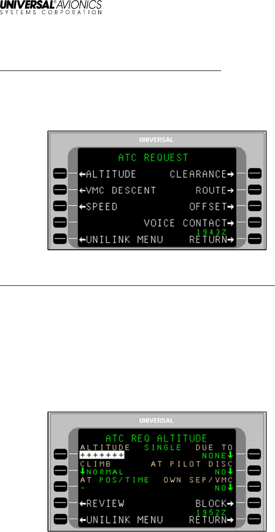
REQUEST
Menu Navigation: UNILINK MENU > ATC > REQUEST
The ATC REQUEST page is used to communicate various flight
operations requests via the CPDLC connection. Each request option
(ALTITUDE, VMC DESCENT, SPEED, etc.) utilizes specific sub-
pages to implement the request.
ALTITUDE
Menu Navigation: UNILINK MENU > ATC > REQUEST > ALTITUDE
Altitude requests can be made for SINGLE or BLOCK altitudes.
SINGLE altitudes are specific, whereas BLOCK altitudes refer to a
range or “block” of altitudes. Consequently, altitude requests will be
made from either the ATC REQ ALTITUDE – SINGLE or ATC REQ
ALTITUDE – BLOCK page.
To make an altitude request – Single Altitude:
1. From the ATC REQUEST page, press ALTITUDE, LSK [1L]. The
ATC REQ ALTITUDE – SINGLE page will display.
UniLink UL-800/801 FANS
SCN 30.X
Operator’s Manual
23-20-06.02 47
December 2011
2. With ALTITUDE active, enter the desired altitude and press
[ENTER].
NOTE: Altitude can be entered as follows:
• Flight Level – Enter the three digit designation for flight level
(370 = FL370), “FL” followed by a three digit number
• Altitude (feet) – Enter the altitude (i.e., 16000)
• Altitude Below 600 ft. – Enter the altitude with a leading 0
(0137 = 137 ft)
• Metric Flight Level – Enter “S” followed by a number
• Altitude (meters) – Enter a number followed by an “M”
Altitude Data Ranges
Units
Lower Limit
Upper Limit
Resolution
Feet 0 25,000 10
Meters 0 16,000 1
Flight Level 030 600 1 (i.e., 100 ft.)
Metric Flight
Level 0100 2000 1 (i.e., 10m.)
3. Press CLIMB, LSK [2L] and toggle between NORMAL and
CRUISE as applicable.
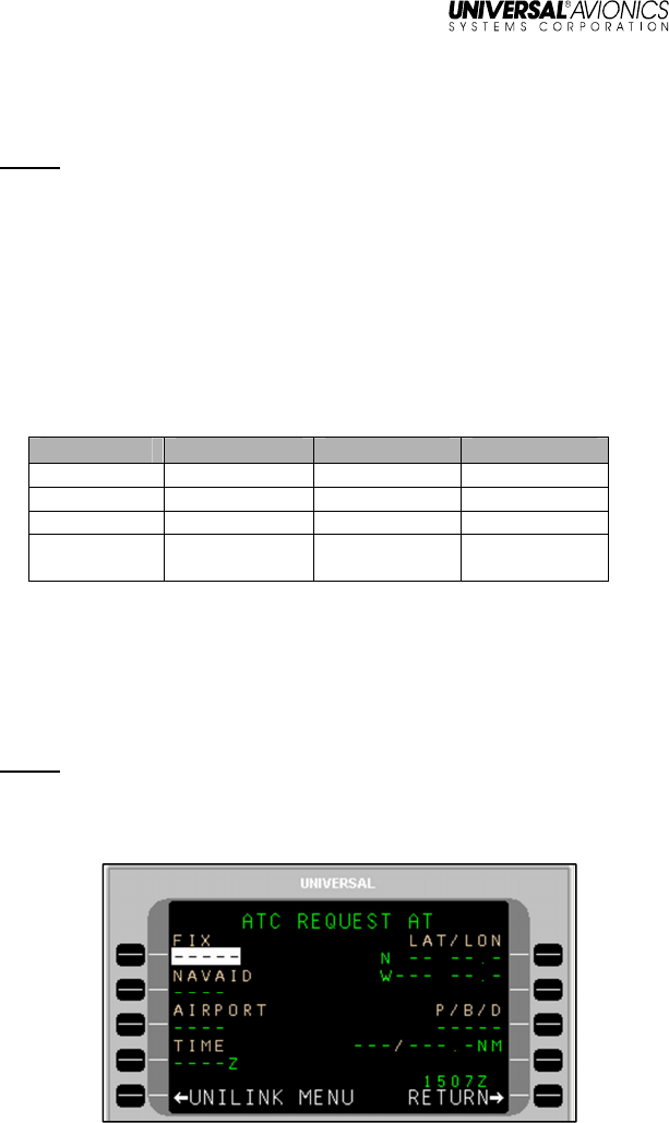
4. Press AT, LSK [3L] (optional). The ATC REQUEST AT screen
will display.
NOTE: When the AT LSK is selected, the CLIMB option will
automatically set to NORMAL; CPDLC does not allow an
altitude request at a position or time to involve a CRUISE
climb.
UniLink UL-800/801 FANS
SCN 30.X
Operator’s Manual
48 23-20-06.02
December 2011
5. Press the appropriate LSK to enter information for FIX, NAVAID,
AIRPORT, TIME (ZULU), LAT/LON, or Place/Bearing/Distance
(P/B/D). Display will return to ATC REQ ALTITUDE page.
6. Press DUE TO, LSK [1R] and toggle between WEATHER, A/C
PERF, or NONE as applicable (default is NONE).
7. Press AT PILOT DISC, LSK [2R] and toggle between NO and
YES to indicate altitude change at the crew’s discretion (default
is NO).
8. Press OWN SEP/VMC, LSK [3R] and toggle between NO and
YES to indicate whether traffic separation will be maintained by
the crew (per VMC rules) or separation will be under ATC control
(default is NO)
9. Press REVIEW, LSK [4L]. The ATC REVIEW 1/X page will
display, reflecting the information entered on the ATC REQ
ALTITUDE page.
NOTE: If no data was entered in the ALTITUDE field, the pop-up
window DATA REQUIRED will display.
10. Press FREE-TEXT, LSK [3L] (optional) and enter information as
needed.
11. Press SEND, LSK [4R] to put the altitude request in queue for
transmission.
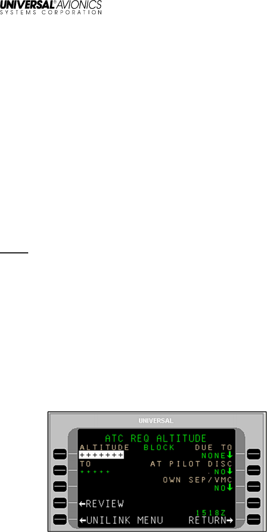
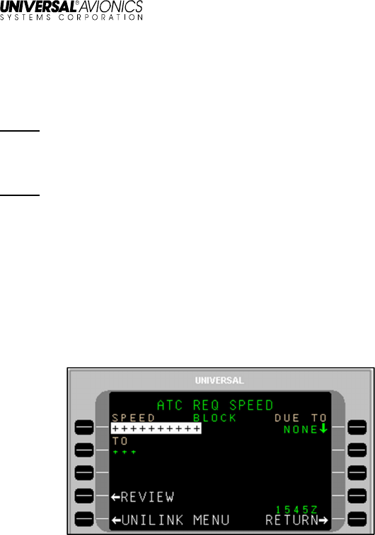
To make an altitude request – Block Altitude:
1. From the ATC REQUEST page, press ALTITUDE, LSK [1L]. The
ATC REQ ALTITUDE – SINGLE page will display.
2. Press BLOCK, LSK [4R]. The ATC REQ ALTITUDE - BLOCK
page will display.
UniLink UL-800/801 FANS
SCN 30.X
Operator’s Manual
23-20-06.02 49
December 2011
3. With ALTITUDE active, enter one end of a desired altitude range
and press [ENTER].
4. If not active, press TO, LSK [2L] and enter the other end of the
desired altitude range. Press [ENTER].
NOTE: Altitude can be entered as follows:
• Flight Level – Enter the three digit designation for flight level
(370 = FL370), “FL” followed by a three digit number
• Altitude (feet) – Enter the altitude (i.e., 16000)
• Altitude Below 600 ft. – Enter the altitude with a leading 0
(0137 = 137 ft)
• Metric Flight Level – Enter S followed by a number
• Altitude (meters) – Enter a number followed by an “M”
Altitude Data Ranges
Units
Lower Limit
Upper Limit
Resolution
Feet 0 25,000 10
Meters 0 16,000 1
Flight Level 030 600 1 (i.e., 100 ft.)
Metric Flight
Level 0100 2000 1 (i.e., 10m.)
5. Press DUE TO, LSK [1R] and toggle between WEATHER, A/C
PERF, or NONE as applicable (default is NONE).
6. Press AT PILOT DISC, LSK [2R] and toggle between NO and
YES to indicate altitude change at the crew’s discretion (default
is NO).
7. Press OWN SEP/VMC, LSK [3R] and toggle between NO and
YES to indicate whether traffic separation will be maintained by
the crew (per VMC rules) or separation will be under ATC control
(default is NO)
8. Press REVIEW, LSK [4L]. The ATC REVIEW 1/X page will
display, reflecting the information entered on the ATC REQ
ALTITUDE-BLOCK page.
NOTE: If no data was entered in the ALTITUDE or TO fields, the pop-
up window DATA REQUIRED will display.
9. Press FREE-TEXT, LSK [3R] and enter information as needed.
10. Press SEND, LSK [4R] to put the altitude request in queue for
transmission.
VMC DESCENT
UniLink UL-800/801 FANS
SCN 30.X
Operator’s Manual
50 23-20-06.02
December 2011
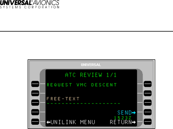
Menu Navigation: UNILINK MENU > ATC > REQUEST > VMC DESCENT
The ATC REVIEW – REQUEST VMC DESCENT page is used to
request a crew-controlled descent under Visual Meteorological
Conditions (VMC) flight rules.
To make a VMC request:
1. Press VMC DESCENT, LSK [2R] on the ATC REQUEST page.
The ATC REVIEW – REQUEST VMC DESCENT page will
display.
2. Press FREE-TEXT, LSK [3L] and enter text as need regarding
the descent request.
3. Press SEND, LSK [4R] to place the message in queue for
transmission.
UniLink UL-800/801 FANS
SCN 30.X
Operator’s Manual
23-20-06.02 51
December 2011
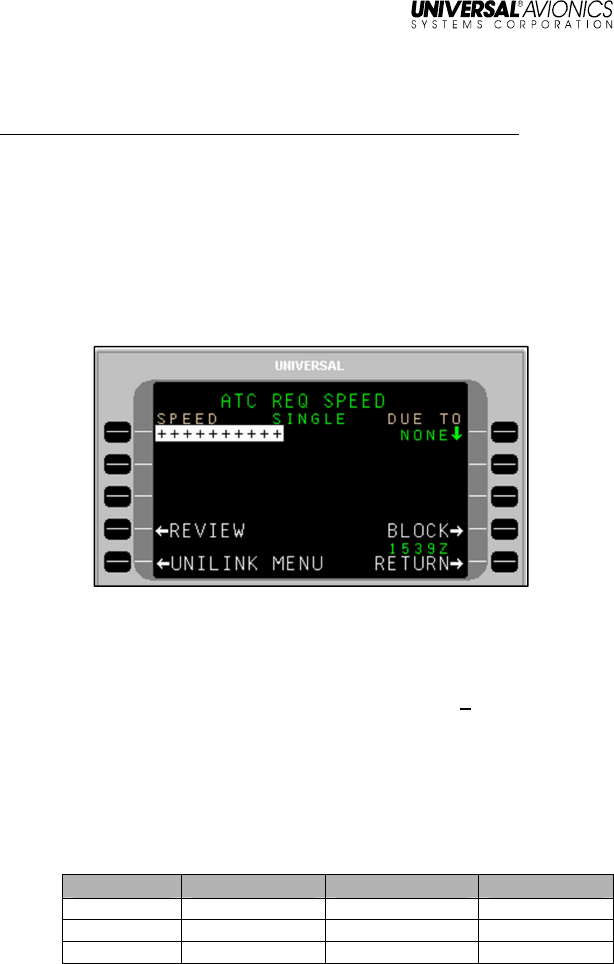
SPEED
Menu Navigation: UNILINK MENU > ATC > REQUEST > SPEED
Speed requests can be made for SINGLE or BLOCK speeds. SINGLE
speeds are specific, whereas BLOCK speeds refer to a speed range
or “block.” Consequently, speed requests will be made from either the
ATC REQ SPEED – SINGLE or ATC REQ SPEED – BLOCK page.
To make a speed request - Single Speed:
1. Press SPEED, LSK [3L] on the ATC REQUEST page. The ATC
REQ SPEED – SINGLE page will display.
2. With SPEED active, enter a desired speed as follows:
• To enter speed in IAS (knots) - enter the speed value (i.e. 235)
and press [ENTER]. The entered value will be followed by IAS.
• To enter a Mach value - type M, use the [ + ] key to place a
period, then enter the value. Press [ENTER] and an M will
display after the entered value.
• To enter speed in IAS KPH – enter the speed value (i.e., 235),
then enter KM and press [ENTER]. The entered value will be
followed by KM IAS.
Speed Data Ranges:
Units
Lower Limit
Upper Limit
Resolution
Knots IAS 70 380 10
KPH IAS 100 1370 10
Mach 0.61 6.04 0.01
3. Press DUE TO, LSK [1R] and toggle between WEATHER, A/C
PERF, or NONE as applicable (default is NONE).
UniLink UL-800/801 FANS
SCN 30.X
Operator’s Manual
52 23-20-06.02
December 2011
4. Press REVIEW, LSK [4L]. The ATC REVIEW 1/X page will
display, reflecting the information entered on the ATC REQ
SPEED page.
NOTE: If no data was entered in the SPPED field, the pop-up window
DATA REQUIERED will display.
5. Press FREE-TEXT, LSK [3L] and enter information as needed.
NOTE: Text is limited to 24 characters on the page (text will not
wrap).
6. Press SEND, LSK [4R] to put the speed request in queue for
transmission.
To make a speed request - Block Speed:
1. From the ATC REQUEST page, press Speed, LSK [3L]. The
ATC REQ SPEED – SINGLE page will display.
2. Press BLOCK, LSK [4R]. The ATC REQ SPEED - BLOCK page
will display.
3. With SPEED active, enter a desired speed as follows:
• To enter speed in IAS (knots) - enter the speed value (i.e. 235)
and press [ENTER]. The entered value will be followed by IAS.
• To enter a Mach value - type M, use the [ + ] key to place a
period, then enter the value. Press [ENTER] and an M will
display after the entered value.
• To enter speed in IAS KPH – enter the speed value (i.e., 235),
then enter KM and press [ENTER]. The entered value will be
followed by KM IAS.
UniLink UL-800/801 FANS
SCN 30.X
Operator’s Manual
23-20-06.02 53
December 2011
Speed Data Ranges:
Units
Lower Limit
Upper Limit
Resolution
Knots IAS 70 380 10
KPH IAS 100 1370 10
Mach 0.61 6.04 0.01
4. Press TO, LSK [2L] and enter the other end of the desired speed
range.
5. Press DUE TO, LSK [1R] and toggle between WEATHER, A/C
PERF, or NONE as applicable (default is NONE).
6. Press REVIEW, LSK [4L]. The ATC REVIEW 1/X page will
display, reflecting the information entered on the ATC REQ
SPEED - BLOCK page.
NOTE: If no data was entered in the SPEED or TO fields, the pop-up
window DATA REQUIERED will display
7. Press FREE-TEXT, LSK [3R] and enter information as needed.
NOTE: Text is limited to 24 characters on the page (text will not
wrap).
8. Press SEND, LSK [4R] to put the altitude request in queue for
transmission.
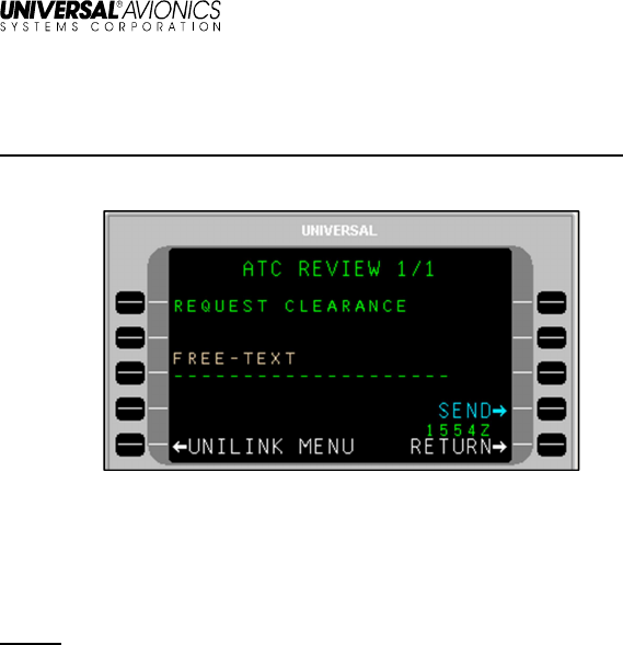
UniLink UL-800/801 FANS
SCN 30.X
Operator’s Manual
54 23-20-06.02
December 2011
CLEARANCE
Menu Navigation: UNILINK MENU > ATC > REQUEST > CLEARANCE
ATC Clearance requests are made utilizing the ATC REVIEW PAGE.
To request ATC clearance:
1. Press CLEARANCE, LSK [1R]. The ATC REVIEW-REQUEST
CLEARANCE page will display.
2. Press FREE-TEXT, LSK [3L] and enter request information.
NOTE: Text is limited to 24 characters on the page (text will not
wrap).
3. Press SEND, LSK [4R] to put the request into queue for
transmission.
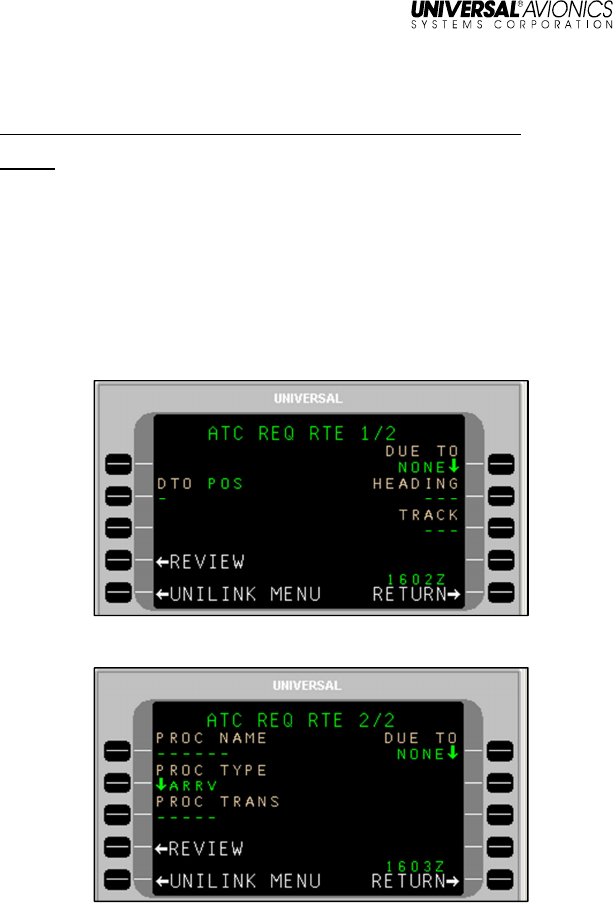
UniLink UL-800/801 FANS
SCN 30.X
Operator’s Manual
23-20-06.02 55
December 2011
ROUTE
Menu Navigation: UNILINK MENU > ATC > REQUEST > ROUTE
NOTE: DTO, Track, Heading, and procedures are all mutually
exclusive. If data is entered in one of these fields, entry of
data in another field prior to sending the request will eliminate
the previous field entry.
The ATC route request pages are used to submit ATC requests for
direct-to routes; arrival, approach, and departure procedures; and
heading clearances. The route request pages include ATC REQ RTE
1/2 and 2/2. Access ATC REQ RTE page 1/2 by selecting ROUTE,
LSK [2R] from the ATC REQUEST page.
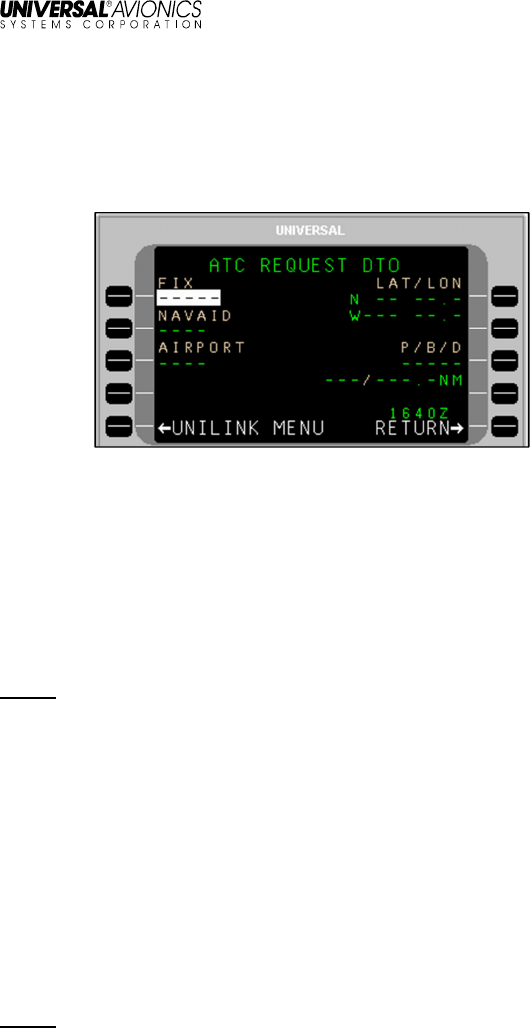
UniLink UL-800/801 FANS
SCN 30.X
Operator’s Manual
56 23-20-06.02
December 2011
Direct-To
To make a Direct-To route request:
1. On the ATC REQ RTE 1/2 page, press DTO, LSK [2L]. The ATC
REQUEST DTO page will display.
2. Press the appropriate LSK to enter information for FIX, NAVAID,
AIRPORT, LAT/LON, or Place/Bearing/Distance (P/B/D). The
display will return to the ATC REQ RTE 1/2 page showing the
entered information at the DTO option.
3. If applicable, press DUE TO, LSK [1R] and toggle between
NONE, WEATHER, and A/C PERF as applicable.
4. Press REVIEW, LSK [4L]. The ATC REVIEW 1/X page will
display showing information from the ATC REQ RTE 1/2 page.
NOTE: If no data was entered in the DTO field, the pop-up window
DATA REQUIRED will display.
5. Press FREE-TEXT, LSK [3R] to add any additional text for the
Direct-To request.
6. Press SEND, LSK [4R] to put the request into queue for
transmission
Heading or Ground Track
To make a heading or ground track route request:
1. On the ATC REQ RTE 1/2 page, press HEADING, LSK [2R], or
TRACK, LSK [3R], as needed.
2. Enter the desired heading or ground track.
NOTE: Entry of a number will result in a magnetic heading. Entry of a
number followed by a “T” will result in a true heading.

UniLink UL-800/801 FANS
SCN 30.X
Operator’s Manual
23-20-06.02 57
December 2011
3. If applicable, press DUE TO, LSK [1R] and toggle between
WEATHER, A/C PERF, or NONE (NONE is the default).
4. Press REVIEW, LSK [4L]. The ATC REVIEW 1/X page will
display showing the information entered on the ATC REQ RTE
1/2 page.
NOTE: If no data was entered in the HEADING or TRACK fields, the
pop-up window DATA REQUIRED will display.
5. Press FREE-TEXT, LSK [3L] and enter additional information as
needed.
6. Press SEND, LSK [4R] to put the request into queue for
transmission.
Procedure - Arrival, Approach, or Departure
To make a Procedure request:
1. On ATC REQ RTE 2/2, press PROC NAME, LSK [1L] and enter
the desired procedure name (up to six alphanumeric characters).
2. Press PROC TYPE, LSK [2L] and toggle between DEPT
(departure), ARRV (arrival), and APPR (approach) as applicable.
3. Press PROC TRANS, LSK [3L] (optional) and enter a transition
(up to five alphanumeric characters).
4. Press REVIEW, LSK [4L]. The ATC REVIEW 1/X page will display
with the procedure request information showing.
NOTE: If no data was entered in the PROC NAME field, the pop-up
window DATA REQUIRED will display.
5. Press FREE-TEXT, LSK [3L] and enter additional information as
needed.
6. Press SEND, LSK [4R] to put the request into queue for
transmission.
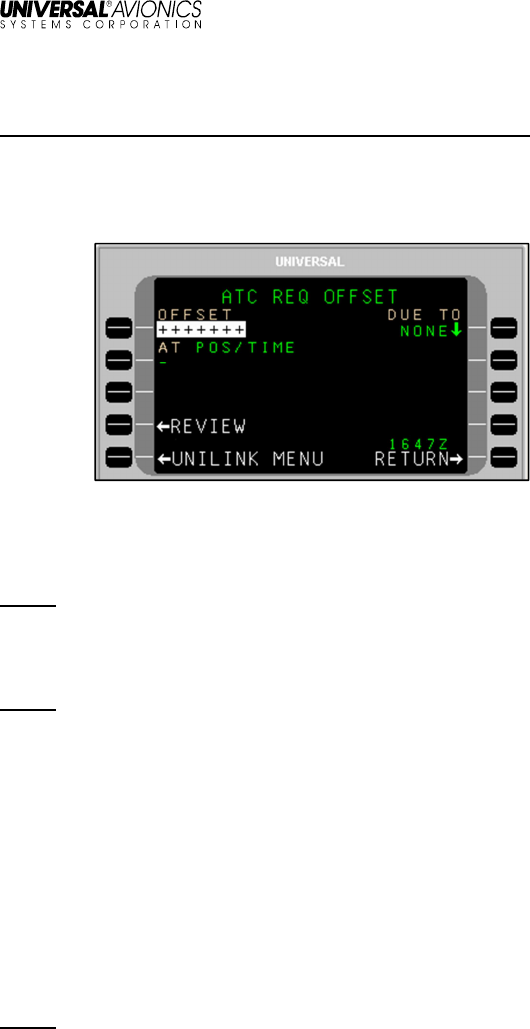
UniLink UL-800/801 FANS
SCN 30.X
Operator’s Manual
58 23-20-06.02
December 2011
OFFSET
Menu Navigation: UNILINK MENU > ATC > REQUEST > OFFSET
An offset request involves specifying to ATC a direction and a lateral
distance (offset) from the desired track (DTK). The ATC REQ
OFFSET page, accessed via LSK [3R] on the ATC REQUEST page,
is used to make an offset request.
To make an Offset request:
1. With OFFSET active, enter an offset distance and press
[ENTER].
NOTE: Entered distance (in NM) must be preceded by an “L” or “R” to
indicate offset side from track. Offset distances must be
between 1 and 128 NM (the UASC FMS has a maximum of
99.9 NM).
NOTE: It is recommended that offsets beyond 25 NM of the original
route be avoided. Greater offsets may cause ETAs in ADS-C
reports to exceed the three-minute error tolerance
requirement.
2. Press AT, LSK [2L] (optional). The ATC REQUEST AT page will
display.
3. Press the appropriate LSK to enter information for FIX, NAVAID,
AIRPORT, TIME (ZULU), LAT/LON, or Place/Bearing/Distance
(P/B/D). The display will return to the ATC REQ OFFSET page
showing the entered information at the AT option.
4. Press DUE TO, LSK [1R] and toggle between WEATHER, A/C
PERF, or NONE (NONE is the default).
NOTE: If no valid entry is made at the AT option and the value of
DUE TO is WEATHER, the ATC REVIEW page will indicate
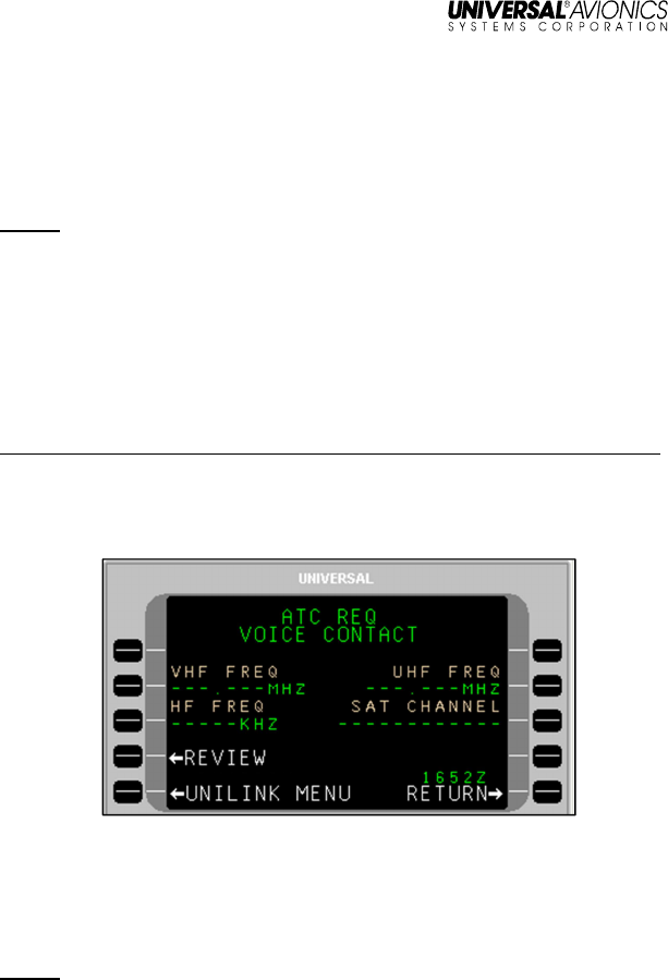
UniLink UL-800/801 FANS
SCN 30.X
Operator’s Manual
23-20-06.02 59
December 2011
REQUEST WEATHER DEVIATION UP TO (offset distance
and direction) OF ROUTE.
5. Press REVIEW, LSK [4L]. The ATC REVIEW 1/X page displays
showing the information from the ATC REQ OFFSET page.
NOTE: If no data was entered in the OFFSET field, the pop-up
window DATA REQUIRED will display.
6. Press FREE-TEXT, LSK [3L] and enter text as needed.
7. Press SEND, LSK [4R] to put the OFFSET request in queue for
transmission.
VOICE CONTACT
Menu Navigation: UNILINK MENU > ATC > REQUEST > VOICE CONTACT
The ATC REQ VOICE CONTACT page, accessed via LSK [4R] on the
ATC REQUEST page, is used to request voice communication with
ATC on a specific frequency or channel.
To make a voice contact request:
1. Press the associated LSK for VHF FREQ, HF FREQ, UHF
FREQ, or SAT CHANNEL as needed. Enter a frequency or
channel.
NOTE: A valid entry at any of the LSKs will invalidate (remove) the
entry at any other LSK made previously.
2. Press REVIEW, LSK [4L]. The ATC REVIEW 1/X page will
display, showing REQUEST VOICE CONTACT and the entered
frequency or channel. (If no frequency or channel was entered,
none will display on the REVIEW page).
3. Press FREE-TEXT, LSK [3L] and enter text as needed.
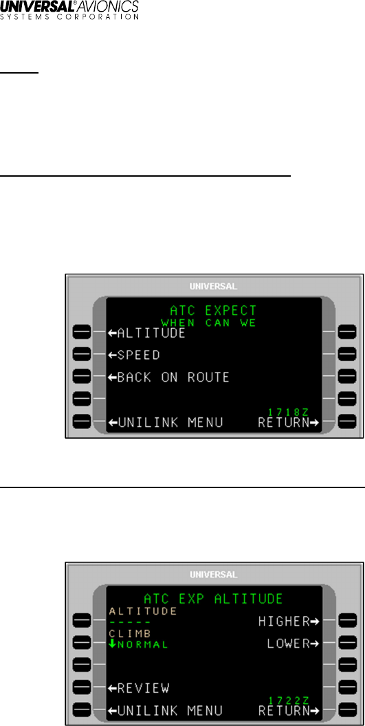
UniLink UL-800/801 FANS
SCN 30.X
Operator’s Manual
60 23-20-06.02
December 2011
NOTE: Text is limited to 24 characters on the page (text will not
wrap).
4. Press SEND, LSK [4R] to put the voice contact request in queue
for transmission.
EXPECT
Menu Navigation: UNILINK MENU > ATC > EXPECT
CPDLC Negotiation Requests (or ATC EXPECT) are used as a follow-
up to previous altitude, speed, or route requests made to ATC (if ATC
has not responded in a timely manner). This is accomplished via the
ATC EXPECT page, accessed by pressing EXPECT, LSK [4L] on the
ATC page.
ALTITUDE
Menu Navigation: UNILINK MENU > ATC > EXPECT > ALTITUDE
To create an altitude negotiation request:
Press ALTITUDE, LSK [1L]. The ATC EXP ALTITUDE page will
display.
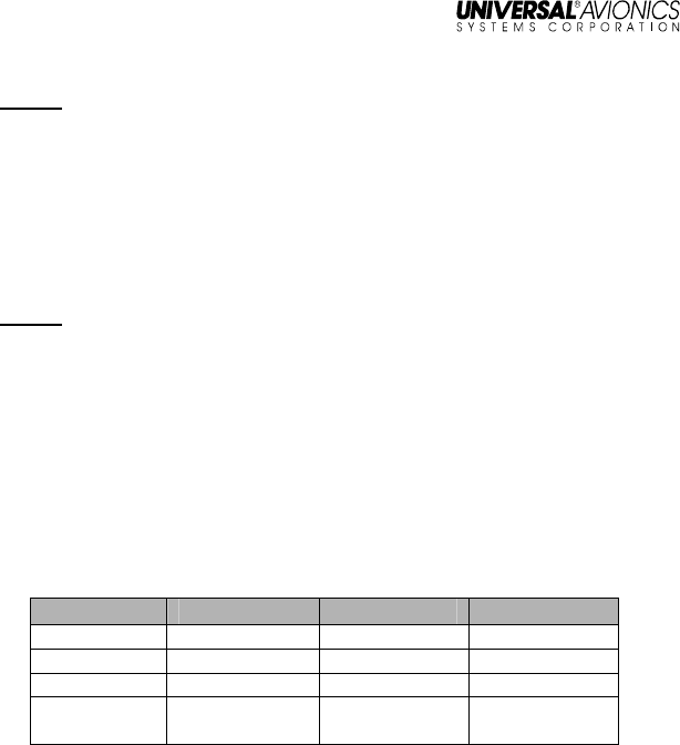
UniLink UL-800/801 FANS
SCN 30.X
Operator’s Manual
23-20-06.02 61
December 2011
NOTE: There are two ways to indicate altitude for the ATC EXP
ALTITUDE request. The user can enter a specific altitude and
indicate the type of climb (if ascending), or the altitude change
can be identified as either HIGHER or LOWER without a
specific altitude indicated.
Specific altitude request:
1. Press ALTITUDE, LSK [1L] and enter a desired altitude.
NOTE: Altitude can be entered as follows:
• Flight Level – Enter the three digit designation for flight level
(370 = FL370), or “FL” followed by a three digit number
• Altitude (feet) – Enter the altitude (16000)
• Altitude Below 600 ft. – Enter the altitude with a leading 0
(0137 = 137 ft)
• Metric Flight Level – Enter “S” followed by a number
• Altitude (meters) – Enter a number followed by “M”
Altitude Data Ranges
Units
Lower Limit
Upper Limit
Resolution
Feet 0 25,000 10
Meters 0 16,000 1
Flight Level 030 600 1 (i.e., 100 ft.)
Metric Flight
Level 0100 2000 1 (i.e., 10m.)
2. Press CLIMB, LSK [2L] and toggle NORMAL or CRUISE as
desired.
General altitude request:
3. Press HIGHER or LOWER (LSKs [1R] or [2R] respectively). An
asterisk (*) will display next to the selection. CLIMB will default to
NORMAL (it is not applicable in a general altitude request).
4. After entering specific or general altitude request information,
press REVIEW, LSK [4L]. The ATC REVIEW 1/X page will
display showing the information entered on the ATC EXP
ALTITUDE page – “WHEN CAN WE EXPECT (specific altitude
value entered information).”
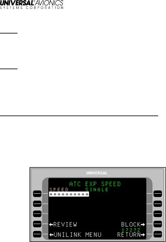
UniLink UL-800/801 FANS
SCN 30.X
Operator’s Manual
62 23-20-06.02
December 2011
NOTE: If no data was entered in the ALTITUDE field, or either
HIGHER or LOWER selected, the pop-up window DATA
REQUIRED will display.
5. Press FREE-TEXT, LSK [3L] and enter text as needed.
NOTE: Text is limited to 24 characters on the page (text will not
wrap).
6. Press SEND, LSK [4R] to put the request in queue for
transmission.
SPEED
Menu Navigation: UNILINK MENU > ATC > EXPECT > SPEED
Speed negotiation requests can be made for specific speeds (Single)
or speed ranges (Block).
Speed – Single:
1. Press SPEED: LSK [2L]. The ATC EXP SPEED – SINGLE page
will display.
2. With SPEED active, enter a desired speed as follows:
• To enter speed in IAS (knots) - enter the speed value (i.e. 235)
and press [ENTER]. The entered value will be followed by IAS.
• To enter a Mach value - type M, use the [ + ] key to place a
period, then enter the value. Press [ENTER] and an M will
display after the entered value.
• To enter speed in IAS KPH – enter the speed value (i.e., 235),
then enter KM and press [ENTER]. The entered value will be
followed by KM IAS.
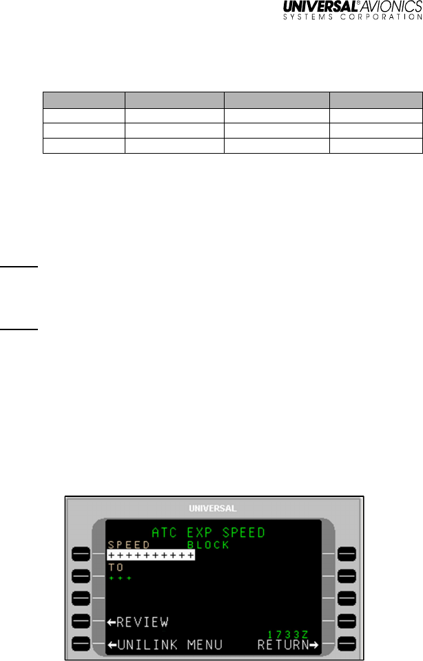
UniLink UL-800/801 FANS
SCN 30.X
Operator’s Manual
23-20-06.02 63
December 2011
Speed Data Ranges:
Units
Lower Limit
Upper Limit
Resolution
Knots IAS 70 380 10
KPH IAS 100 1370 10
Mach 0.61 6.04 0.01
3. Press REVIEW, LSK [4L]. The ATC REVIEW 1/X page will
display showing the entered speed from the ATC EXP SPEED –
SINGLE page: “WHEN CAN WE EXPECT (specific speed value
entered).”
NOTE: If no data was entered in the SPEED field, the pop-up window
DATA REQUIERED will display
4. Press FREE-TEXT, LSK [3L] and add text as needed.
NOTE: Text is limited to 24 characters on the page (text will not
wrap).
5. Press SEND, LSK [4R] to put the speed negotiation request into
queue for transmission.
Speed – Block:
1. Press SPEED: LSK [2L]. The ATC EXP SPEED – SINGLE page
will display.
2. Press BLOCK, LSK [4R]. The ATC EXP SPEED – BLOCK page
will display.
3. With SPEED active, enter the bottom of the desired speed range:
• To enter speed in IAS (knots) - enter the speed value (i.e. 235)
and press [ENTER]. The entered value will be followed by IAS.
UniLink UL-800/801 FANS
SCN 30.X
Operator’s Manual
64 23-20-06.02
December 2011
• To enter a Mach value - type M, use the [ + ] key to place a
period, then enter the value. Press [ENTER] and an M will
display after the entered value.
• To enter speed in IAS KPH – enter the speed value (i.e., 235),
then enter KM and press [ENTER]. The entered value will be
followed by KM IAS.
Speed Data Ranges:
Units
Lower Limit
Upper Limit
Resolution
Knots IAS 70 380 10
KPH IAS 100 1370 10
Mach 0.61 6.04 0.01
4. In the TO field, enter top of the desired speed range.
5. Press REVIEW, LSK [4L]. The ATC REVIEW 1/X page will
display showing the entered speeds from the ATC EXP SPEED –
BLOCK page. – “WHEN CAN WE EXPECT (speed value
entered).TO (speed value entered).”
NOTE: If no data was entered in the SPEED or TO fields, the pop-up
window DATA REQUIERED will display
6. Press FREE-TEXT, LSK [3L] and add text as needed.
NOTE: Text is limited to 24 characters on the page (text will not
wrap).
7. Press SEND, LSK [4R] to put the speed negotiation request into
queue for transmission.
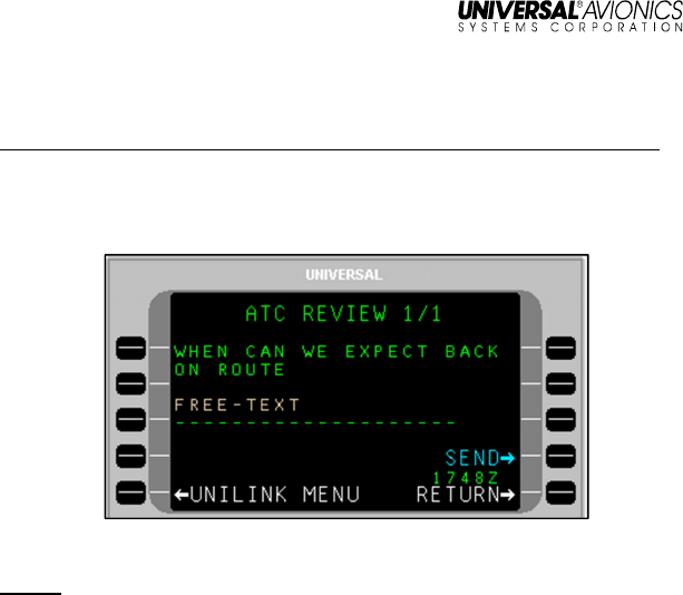
UniLink UL-800/801 FANS
SCN 30.X
Operator’s Manual
23-20-06.02 65
December 2011
BACK ON ROUTE
Menu Navigation: UNILINK MENU > ATC > EXPECT > BACK ON ROUTE
1. Press BACK ON ROUTE, LSK [3L]. The ATC REVIEW 1/1 page
will display showing “WHEN CAN WE EXPECT BACK ON
ROUTE.”
2. Press FREE-TEXT, LSK [3L] and enter text as needed.
NOTE: Text is limited to 24 characters on the page (text will not
wrap).
3. Press SEND, LSK [4R] to put the speed negotiation request into
queue for transmission.
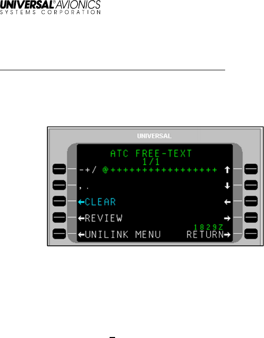
UniLink UL-800/801 FANS
SCN 30.X
Operator’s Manual
66 23-20-06.02
December 2011
ATC FREE-TEXT
Menu Navigation: UNILINK MENU > ATC > FREE-TEXT
General purpose communications with ATC can be performed through
the FREE-TEXT function. Communications of a non-emergency
nature or general inquiries are made using the ATC FREE-TEXT
page.
To send a text message:
1. Press FREE-TEXT, LSK [1R] on the ATC page. The ATC FREE-
TEXT 1/1 page will display with the cursor (@) flashing at the
beginning of the text line.
2. Enter text (alphanumeric keys) as needed.
• The plus/minus [ + ] key is used to insert a space ([SP] key on
MCDU). The text automatically word wraps to the next line.
The number of pages in the message will increase as
necessary to accommodate entered text.
• LSKs [1L] and [2L] are used to insert special characters as
indicated on the display. Selecting the same special character
key multiple times will cause the selected character to cycle
between the displayed choices. To enter a special character
several times in a row, select another key between special
character LSK presses (example: to enter several periods in a
row, press LSK [2R], then the right-arrow key (which does
nothing), then [2R], then the right-arrow key, etc.).
• The arrow LSKs ([1R] through [4R]) will move the cursor
position within the text that has been entered.

UniLink UL-800/801 FANS
SCN 30.X
Operator’s Manual
23-20-06.02 67
December 2011
3. To delete entire message, press CLEAR, LSK [3L].
4. When finished entering text, press REVIEW, LSK [4L]. The ATC
REVIEW 1/X page will display showing text entered on the ATC
FREE-TEXT page.
NOTE: If no text was entered on the FREE-TEXT page, the pop-up
window DATA REQUIRED will display.
5. Press SEND, LSK [4R] to put the message into queue for
transmission.
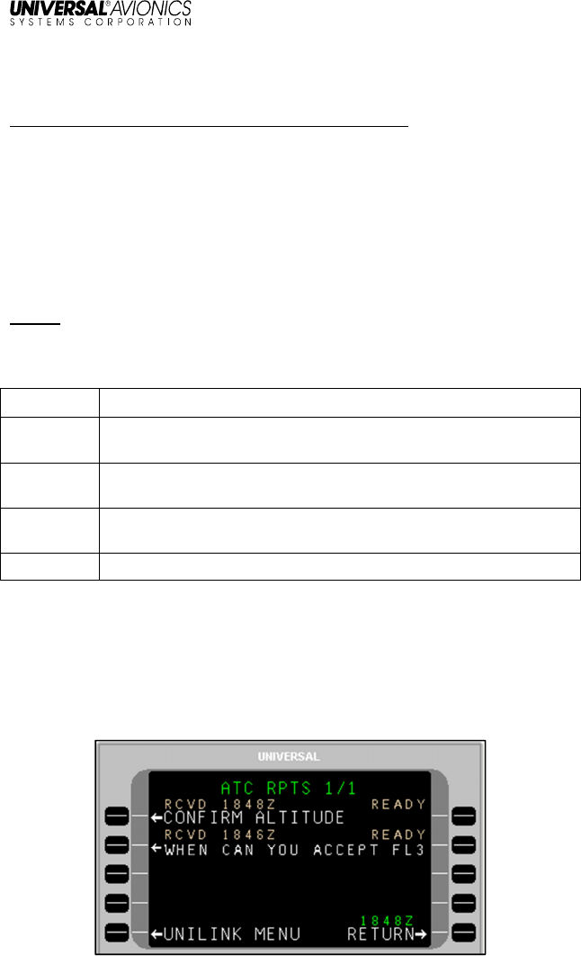
UniLink UL-800/801 FANS
SCN 30.X
Operator’s Manual
68 23-20-06.02
December 2011
RPTS LIST
Menu Navigation: UNILINK MENU > ATC > RPTS LIST
The RPTS (reports) LIST function provides a listing (displayed on the
ATC RPTS 1/X page) of the 15 oldest unanswered report requests by
ATC, with the most recent request shown first. As reports successfully
complete transmission (i.e., receive an ACARS network
acknowledgement), they are deleted from the RPTS LIST. The
number of pages of the ATC RPTS screen is dependent on the
number of requested reports. UniLink displays up to four report
requests per page for a maximum of four pages.
NOTE: A report requested by ATC can be accessed and sent via the
ATC RPTS 1/X page.
Report Statuses include:
Status Description
PENDING UniLink has not yet determined that the conditions have been
met for the report to be sent.
READY UniLink has determined that the conditions have been met for
the report to be sent.
QUEUED UniLink placed the report in its downlink queue but has not yet
successfully transmitted it.
SENDING UniLink is transmitting the report.
To view the Reports List:
1. On the ATC page press RPTS LIST, LSK [2R]. The ATC RPTS
1/X page will display, showing the 15 oldest unanswered report
requests in queue. Above each report is displayed the time the
report was received and its status.
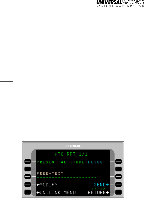
UniLink UL-800/801 FANS
SCN 30.X
Operator’s Manual
23-20-06.02 69
December 2011
NOTE: If the request title is truncated (as in the above example due to
no text wrapping), the complete title can be viewed on an ATC
MSG page.
2. To view a specific report response, press the left LSK adjacent
the listed request.
3. To delete a specific report, press the adjacent right-hand LSK. A
pop-up window will display to DELETE or CANCEL; press the
desired LSK.
4. Press RETURN, LSK [5R] to return to the ATC page.
NOTE: UniLink does not detect duplicate uplink ATC requests. This
must be done by the crew.
To respond to an ATC report request:
1. On the ATC RPTS 1/X page, find the requested report.
2. Press the left-hand LSK adjacent the report. If UniLink is capable
of prefilling the data required in the report, the ATC RPT 1/1
page will display showing the requested information. If UniLink
does not have enough information to prefill the report, a data
entry page will display depending on the specific report data
required.
(Example of an ATC RPT page)
3. If needed, press MODIFY, LSK [4L]. Depending on the requested
information, the ATC report page will display (such as ATC
PRESENT ALTITUDE or ATC ASSIGNED ROUTE).
4. Modify the information as needed and press REVIEW, LSK [4L].
The ATC RPT page displays showing the changed information.
5. As needed, press FREE-TEXT, LSK [3L] and enter text.

UniLink UL-800/801 FANS
SCN 30.X
Operator’s Manual
70 23-20-06.02
December 2011
6. Press SEND, LSK [4R] to put the message in queue for
transmission.
Immediate and Delayed Reports and Requests
There are over 20 possible report or request pages, categorized as
either Immediate or Delayed.
Immediate Requests and Reports
Immediate uplink requests and reports, listed in Table 1, do not
require a ROGER response and can be fulfilled immediately. If
UniLink receives a valid Data Transaction uplink containing a request,
that request will be added to the RPTS LIST with status pending.
NOTE: Data statuses include:
• Sufficient = UniLink supplies the necessary data on the page
• Insufficient = UniLink cannot supply all the data and it will need
to be entered
• No Data = No data is required for the communication
TABLE 1 – Immediate Reports and Requests
Uplink Requests
Downlink Reports
Display
Display
Data
CONFIRM ALTITUDE PRESENT ALTITUDE
[altitude] Sufficient
CONFIRM POSITION PRESENT POSITION
[position] Sufficient
CONFIRM SPEED PRESENT SPEED [speed] Sufficient
CONFIRM HEADING PRESENT HEADING
[degrees] Sufficient
CONFIRM GROUND
TRACK PRESENT GROUND TRACK
[degrees] Sufficient
CONFIRM
ASSIGNED
ALTITUDE
ASSIGNED ALTITUDE
[altitude] Sufficient
ASSIGNED BLOCK [altitude]
TO [altitude] Insufficient
CONFIRM
ASSIGNED SPEED ASSIGNED SPEED [speed] Insufficient
CONFIRM NEXT
WAYPOINT NEXT WAYPOINT [position] Sufficient
CONFIRM NEXT NEXT WAYPOINT ETA [time] Sufficient

UniLink UL-800/801 FANS
SCN 30.X
Operator’s Manual
23-20-06.02 71
December 2011
Uplink Requests
Downlink Reports
Display
Display
Data
WAYPOINT ETA
CONFIRM ENSUING
WAYPOINT
ENSUING WAYPOINT
[position]
Sufficient
CONFIRM
REPORTED
WAYPOINT
REPORTED WAYPOINT
[position] Sufficient
CONFIRM TIME
OVER REPORTED
WAYPOINT
REPORTED WAYPOINT
[time] Sufficient
CONFIRM SQUAWK SQUAWKING [beacon code] Insufficient
REQUEST POSITION
REPORT POSITION REPORT [position
report] Insufficient
REPORT
REMAINING FUEL
AND SOULS ON
BOARD
[remaining fuel] OF FUEL
REMAINING AND [remaining
souls] SOULS ON BOARD Insufficient
WHEN CAN YOU
ACCEPT [altitude]
WE CAN ACCEPT [altitude]
AT [time] Insufficient
WE CAN ACCEPT [altitude]
AT [position] Insufficient
WE CANNOT ACCEPT
[altitude] Insufficient
WHEN CAN YOU
ACCEPT [speed]
WE CAN ACCEPT [speed] AT
[time] Insufficient
WE CAN ACCEPT [speed] AT
[position] Insufficient
WE CANNOT ACCEPT
[speed] Insufficient
WHEN CAN YOU
ACCEPT [distance
offset] [direction]
OFFSET
WE CAN ACCEPT [distance
offset] [direction] OFFSET AT
[time] Insufficient
WE CAN ACCEPT [distance
offset] [direction] OFFSET AT
[position] Insufficient
WE CANNOT ACCEPT
[distance offset] [direction] Insufficient

UniLink UL-800/801 FANS
SCN 30.X
Operator’s Manual
72 23-20-06.02
December 2011
Uplink Requests
Downlink Reports
Display
Display
Data
OFFSET
CONFIRM
ASSIGNED ROUTE CONFIRM ASSIGNED
ROUTE NOT SUPPORTED No Data
REPORT DISTANCE
[to from] [position] AT [time] [distance] [to from]
[position] Insufficient
CONFIRM ATIS
CODE ATIS [ATIS code] Insufficient
Delayed Requests and Reports
Delayed uplink requests and reports, listed in Table 2, do require a
ROGER response and cannot be fulfilled immediately. If the crew
queues a positive downlink closure response (i.e., ROGER]) to a Data
Transaction uplink containing a delayed request, UniLink will add the
request to the RPTS LIST with status pending.
NOTE: Data statuses include:
• Specified = All data is specified by ATC
• No Data = No data is required for the communication
TABLE 2 – Delayed Reports and Requests
Uplink Reports
Downlink Reports
Display
Display
Data
REPORT LEAVING
[altitude] LEAVING [altitude] Specified
REPORT PASSING
[position] PASSING [position] Specified
REPORT LEVEL
[altitude] LEVEL [altitude] Specified
REPORT BACK ON
ROUTE BACK ON ROUTE No Data
REPORT REACHING
[altitude] REACHING [altitude] Specified
REPORT REACHING
BLOCK [altitude] TO
[altitude]
REACHING BLOCK [altitude]
TO [altitude] Specified

UniLink UL-800/801 FANS
SCN 30.X
Operator’s Manual
23-20-06.02 73
December 2011
Delayed Report and Request downlinks are auto-generated. If UniLink
designates a delayed uplink request as READY, a FANS visual alert is
activated in addition to displaying the ATC RPT READY advisory. The
crew may access the ATC RPTS LIST and send any report at any
time regardless of UniLink PENDING/READY designation. The
PENDING/READY designation and ATC RPT READY advisory are
intended to aid in the timely response of reports, but it is ultimately the
responsibility of the crew to ensure reports are transmitted at the
appropriate time.
NOTE: The BACK ON ROUTE downlink can only be sent in response
to a REPORT BACK ON ROUTE uplink. The crew must use
voice communication to report BACK ON ROUTE in the
absence of an uplink.
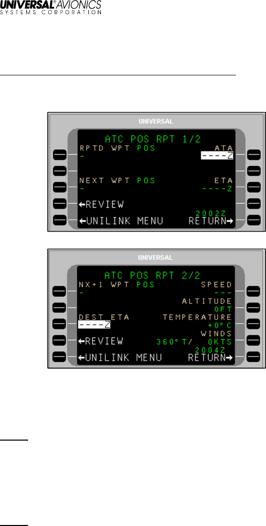
UniLink UL-800/801 FANS
SCN 30.X
Operator’s Manual
74 23-20-06.02
December 2011
POS REPORT
Menu Navigation: UNILINK MENU > ATC > POS REPORT
The POS (Position) REPORT function allows the user to make a
position report to ATC. A report is made via ATC POS RPT pages.
To make a position report:
1. Press POS REPORT, LSK [3R] on the ATC page. ATC POS
RPT 1/2 will display.
NOTE: ATC POS RPT can also be accessed from the RPTS 1/X
page if a position report request has been received.
2. Review the auto-filled information in the fields on pages 1/2 and
2/2.
3. If any information is missing or incorrect, press the adjacent LSK
and enter the correct information.
NOTE: ALTITUDE is required. All other information is optional.
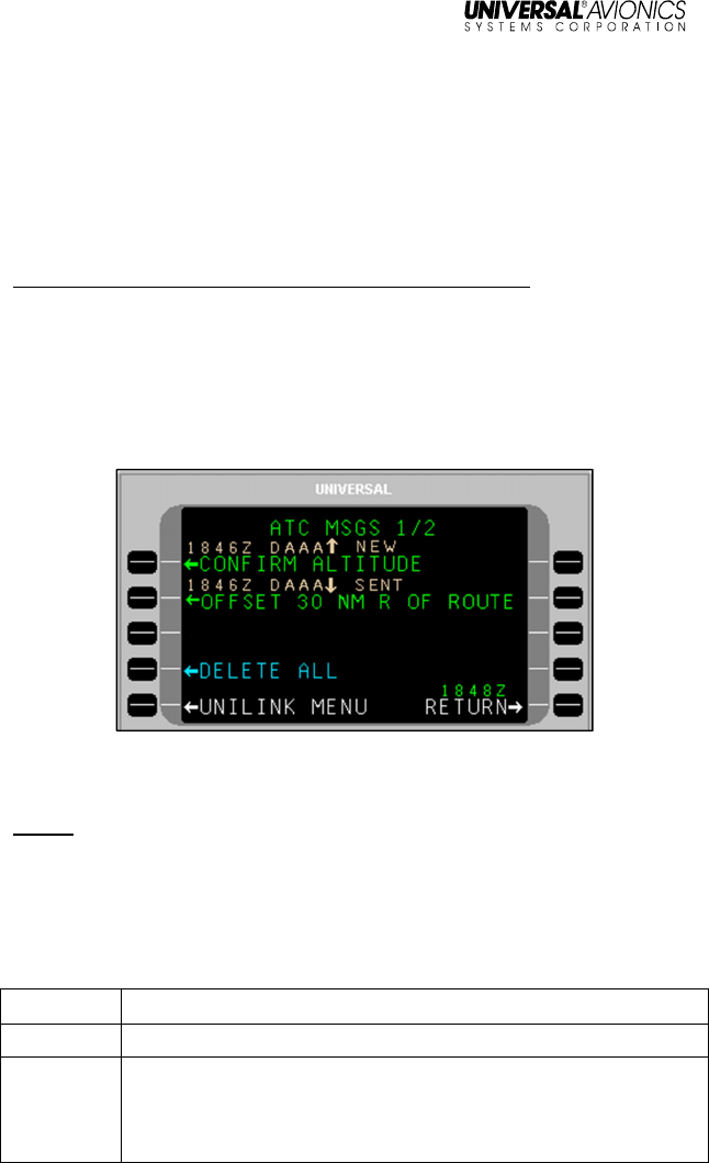
UniLink UL-800/801 FANS
SCN 30.X
Operator’s Manual
23-20-06.02 75
December 2011
4. Press REVIEW, LSK [4L]. The ATC REVIEW page with
information for the position report will display.
5. Press SEND, LSK [4R] to put the position report in queue for
transmission.
ATC MSG LOG
Menu Navigation: UNILINK MENU > ATC >ATC MSG LOG
The ATC Message Log (ATC MSG LOG) function provides a log of up
to 150 of the most recent viewable messages exchanged with ATC
(75 most recently received and 75 most recently queued), with the
newest message shown first. The message entries are displayed on
the ATC MSGS 1/X page, accessed from the ATC page by pressing
ATC MSG LOG (LSK [4R]).
The ATC MSG LOG page allows users to review and/or print a
message (if a printer is configured).
NOTE: The number of pages of the ATC MSGS screen is dependent
on the number of viewable messages that UniLink has logged.
ATC MSGS displays up to four messages per page (except
for the first page which lists a maximum of three). ATC MSGS
may be composed of up to 38 pages.
UniLink assigns a status to each uplink message as follows:
Status Description
NEW UniLink has not yet displayed the uplink message to the user.
OLD UniLink has displayed the uplink message to the user and the
message does not require a downlink closure response
message from the user.

UniLink UL-800/801 FANS
SCN 30.X
Operator’s Manual
76 23-20-06.02
December 2011
OPEN UniLink has displayed the uplink message to the user but the
message requires a downlink closure response message from
the user.
WILCO
hhmmZ UniLink sent a WILCO downlink closure response message
initiated by the user at the indicated time.
UNABLE
hhmmZ UniLink sent an UNABLE downlink closure response message
initiated by the user at the indicated time.
AFFIRM
hhmmZ UniLink sent an AFFIRM downlink closure response message
initiated by the user at the indicated time.
NEGATV
hhmmZ UniLink sent a Negative downlink closure response message
initiated by the user at the indicated time.
ROGER
hhmmZ UniLink sent a ROGER downlink closure response message
initiated by the user at the indicated time.
STANDBY UniLink sent a STANDBY downlink response message initiated
by the user.
ABORTD
hhmmZ UniLink aborted the uplink message at the indicated time
because it closed the CPDLC connection.
UniLink assigns a status to each downlink message as follows:
Status Description
QUEUED UniLink placed the downlink message in its downlink queue
but has not yet successfully transmitted it.
SENDING
[medium] UniLink is transmitting the downlink message via the indicated
medium. (The possible media are VHF and SAT [SATCOM],
depending on UniLink configuration).
SENT
hhmmZ UniLink successfully transmitted a downlink message at the
indicated time that does not require an uplink closure response
message from ATC.
OPEN UniLink successfully transmitted a downlink that requires an
uplink closure response message from ATC.
UNABLE
hhmmZ UniLink received an UNABLE uplink closure response
message from ATC at the indicated time.
STANDBY UniLink received a STANDBY uplink response message from
ATC.
DEFERRED UniLink received a REQUEST DEFERRED uplink response
message from ATC.
ROGER
hhmmZ UniLink received a ROGER uplink closure response message
from ATC at the indicated time.
AFFIRM UniLink received an AFFIRM uplink closure response message

UniLink UL-800/801 FANS
SCN 30.X
Operator’s Manual
23-20-06.02 77
December 2011
Status Description
hhmmZ from ATC at the indicated time.
NEGATV
hhmmZ UniLink received a NEGATIVE uplink closure response
message from ATC at the indicated time.
CLOSED
hhmmZ UniLink received an uplink closure response message other
than ROGER, AFFIRM, NEGATIVE, or UNABLE from ATC at
the indicated time.
ABORTD
hhmmZ UniLink aborted the downlink message at the indicated time
because it closed the CPDLC connection.
To review a message:
1. On the ATC MSGS page, locate the message of interest.
2. Press the left LSK adjacent that message. While displaying the
detailed message page, pressing [PREV] and [NEXT] can be
used to navigate multiple page messages. .
3. Press RETURN to return to the ATC MSGS page.
To delete all messages in the messages log:
1. On the ATC MSGS 1/X page, press DELETE ALL, LSK [4L]. A
CONFIRM/CANCEL pop-up window will display.
2. Press CONFIRM to delete all entries or CANCEL to cancel the
DELETE ALL function.
To delete or print messages in the messages log:
1. On the ATC MSGS page, press the adjacent right-hand LSK. A
PRINT/DELETE/CANCEL pop-up menu will display.
2. Press the desired LSK (to print or delete).
3. Press the CANCEL LSK to cancel the function.
NOTE: PRINT will display on the pop-up menu only if a printer is
configured.
To print a message from the detailed message display:
1. On the ATC MSGS page, locate the message of interest.
2. Press the adjacent left-hand LSK. The ATC MSG screen will
display with the selected message showing.
3. Press the PRINT LSK.
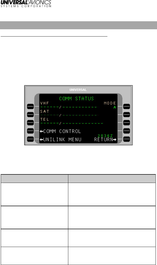
UniLink UL-800/801 FANS
SCN 30.X
Operator’s Manual
78 23-20-06.02
December 2011
COMM STATUS
Menu Navigation: UNILINK MENU > COMM STATUS
The COMM STATUS page displays the current configured status of
available communication media links.
MODE
The MODE field indicates the manner in which ACARS will be used.
• MODE A = POA (Plain Old ACARS)
• MODE B = AOA (AVLC Over ACARS)
Based on the aircraft installation and configuration, all three media
statuses may or may not display. If not configured, the media title will
not display and the position on the page will be empty. The possible
statuses include:
VHF Media Status Reason
COMM / IDLE Communications have been established
with the ground and datalink messages
can be transmitted over VHF. No data is
currently being transmitted.
COMM / SENDING A message is currently in the process of
being transmitted over VHF and UniLink
is waiting for acknowledgement from the
ground.
NOCOMM / NO FREQ UniLink has not selected a frequency for
tuning due to invalid FMS lat/long or no
radio type
NOCOMM / SCANNING UniLink is automatically selecting a
frequency for tuning in current region
with enabled DSP.

UniLink UL-800/801 FANS
SCN 30.X
Operator’s Manual
23-20-06.02 79
December 2011
VHF Media Status Reason
NOCOMM / CONNECTING UniLink has sent communication to the
ground and is awaiting a reply.
NOCOMM / NO DSP All DSPs have been manually selected
OFF.
NOCOMM / VOICE The VDR is in VOICE mode.
NOTE: Does not apply to UL-801 with
internal VDR.
NOCOMM/VDR INOP VDR inoperative.
NOCOMM/VDR FAULT VDR is reporting a fault.
NOCOMM/VDR UNAVAIL UniLink has not set the VDR’s protocol
state.
NOCOMM/MONITORING UniLink has not detected a viable VDL
Mode 2 ground station.
NOCOMM/SUSPEND VHF communications have been
suspended by the crew.
SatCom Media Status Reason
COMM / IDLE SatCom (SAT) communication has been
established and datalink messages can
be transmitted over SatCom. No data is
currently being transmitted.
COMM / SENDING A message is currently in the process of
being transmitted. UniLink is waiting for
acknowledgement from the ground.
NOCOMM / SDU UNAVAIL
NOTE: SDU is the Satellite
Data Unit.
The SatCom’s system SDU is reporting
that it is unavailable.
NOCOMM / SDU INOP UniLink does not detect the SDU.
NOCOMM / AUTO DELAY UniLink is waiting before trying to
establish a SatCom (SAT) link again.
NOCOMM / TIMEOUT Retries have been exhausted, and Auto
Return to Comm configuration setting is
disabled. A manual Link Test must be
performed, or an uplink received for the
medium to return to COMM.
NOCOMM / CONNECTING A SatCom (SAT) link is in the process of
being established.

UniLink UL-800/801 FANS
SCN 30.X
Operator’s Manual
80 23-20-06.02
December 2011
SatCom Media Status Reason
NOCOMM/SUSPENDED SatCom (SAT) link has been suspended
by the crew.
TEL Media Status Reason
COMM / MDM TIMEOUT UniLink has dialed the phone but a
timeout occurred prior to a
connection being established.
NOTE: Sequential, excessive
timeouts will result in the NOCOMM /
AUTO DELAY message displaying.
COMM / DIALING UniLink has provided the phone with
the dial string command and is
waiting for the phone to answer.
COMM / CONNECTING The ground has answered the phone
and UniLink is communicating with
the DSP
COMM / IDLE The phone is hung up and no
attempt is currently being made to
use it and SatCom (TEL) is not
suspended or waiting to retry.
COMM / CONNECTED The phone line is connected and
messages can or are currently being
transferred.
COMM / PLEASE WAIT TEL SUSPEND has been manually
activated. UniLink is in the process
of shutting down the connection.
NOCOMM / SUSPENDED SatCom (TEL) has been suspended,
either by the crew or automatically
due to excessive failed attempts.
NOCOMM / AUTO DELAY UniLink is waiting for the
configurable AUTO-DELAY timer to
expire before trying again

UniLink UL-800/801 FANS
SCN 30.X
Operator’s Manual
23-20-06.02 81
December 2011
TEL Media Status Reason
NOCOMM / CONFIG FAIL While CONNECTING with the
ground server, a message is
received saying the configuration
sent by UniLink is invalid. The
SatCom (TEL) system is
permanently shut down. Cycling
UniLink power is required to exit this
state.
NOCOMM / INIT FAIL The SatCom (TEL) system is not
available for operation. One or both
of the following configuration items
are invalid: Aircraft Registration
Number, or Phone Access Number.
NOCOMM / DIALING UniLink exited out of the 5-minute
delay and is in the process of making
another connection attempt.
NOCOMM / PLEASE WAIT TEL SUSPEND has been manually
activated while a connection is in
progress. UniLink is in the process of
shutting down the connection.
NOCOMM / MDM
TIMEOUT UniLink exited out of the 5-minute
delay and while in the process of
making another connection attempt
the UniLink modem has timed out.
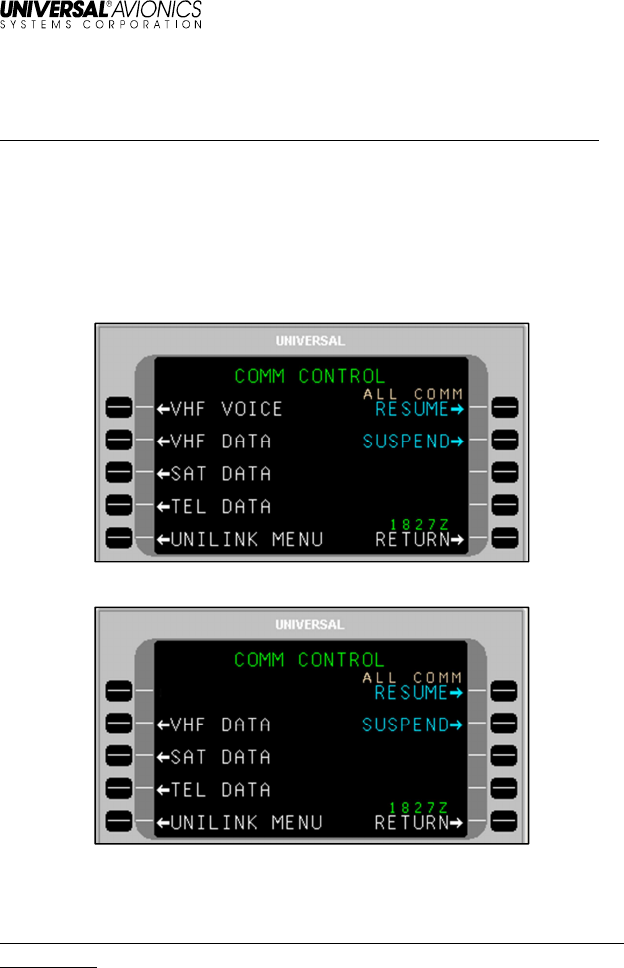
UniLink UL-800/801 FANS
SCN 30.X
Operator’s Manual
82 23-20-06.02
December 2011
COMM CONTROL
Menu Navigation: UNILINK MENU > COMM STATUS > COMM CONTROL
The COMM CONTROL page provides access to media control pages
and options. Access the COMM CONTROL page by selecting COMM
STATUS, LSK [3L] from the UNILINK MENU page. Then select
COMM CONTROL, LSK [4L] from the COMM STATUS page to
display the COMM CONTROL page. The COMM CONTROL page
gives access to VHF VOICE (UL-800 only), VHF DATA, SAT DATA,
and TEL DATA options (as configured and installed).
UL-800 with External VDR
UL-801 with Internal VDR
VHF Voice (UL-800 only)
Menu Navigation: UNILINK MENU > COMM STATUS > COMM CONTROL >
VHF VOICE
The VHF VOICE option is available if the VHF radio supports voice
communications (does not apply to UL-801 with internal VDR).
Pressing VHF VOICE, LSK [1L] from the COMM CONTROL page
displays the VHF VOICE page.
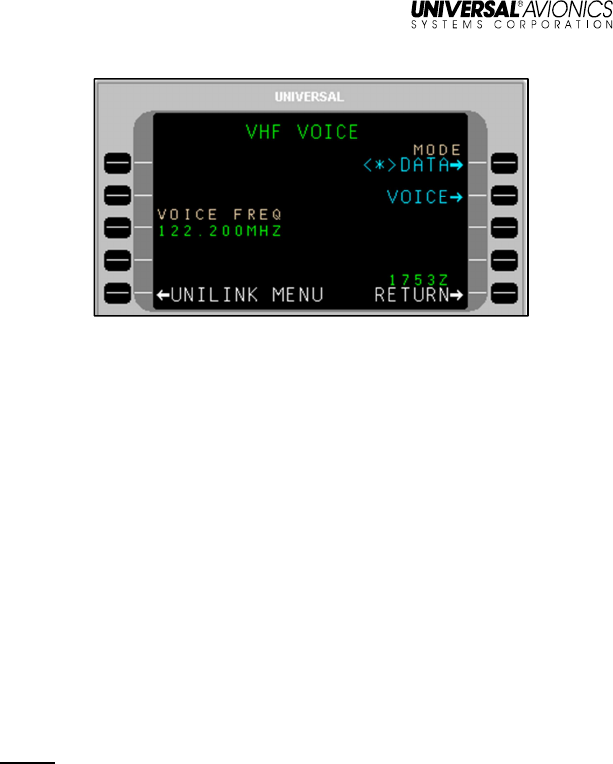
UniLink UL-800/801 FANS
SCN 30.X
Operator’s Manual
23-20-06.02 83
December 2011
UL-800 with External VDR
The VHF VOICE page is used to enable/disable VHF voice mode.
LSKs [1R] and [2R] allow selection of the MODE as either DATA or
VOICE respectively (an asterisk <*> indicates the selected mode).
DATA Mode - UniLink data communication; no voice communications.
UniLink will tune to the appropriate datalink frequencies only.
VOICE Mode - UniLink no longer communicates via VHF to support
datalink communications. The external VDR is used for voice and
voice frequencies are tuned via VOICE FREQ, LSK [3L].
VHF voice frequency can be tuned from this page if Voice Frequency
Control enabled in configuration. Valid frequency range is:
• If configured for frequency spacing of 25KHz - 118.000 to
136.950
• If configured for frequency spacing of 25KHz/8.33KHz -
118.000 to 136.965 and 136.980 to 136.990
NOTE: The frequency 136.975 is a reserved frequency.
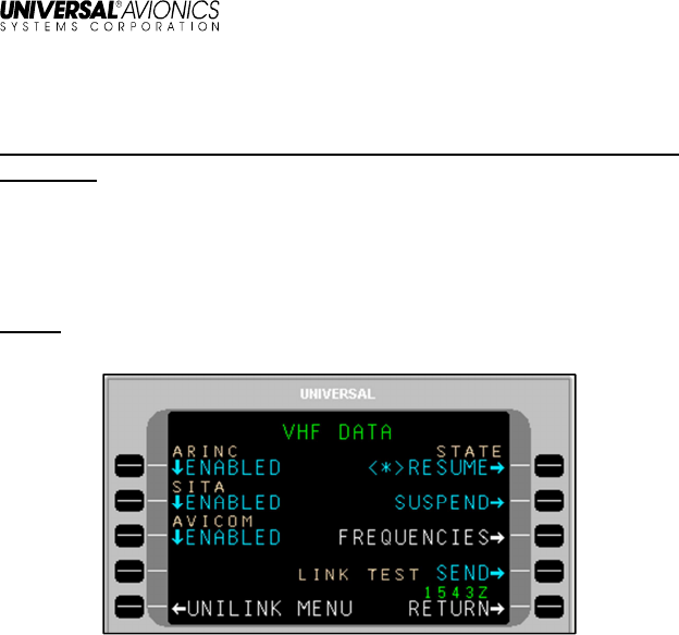
UniLink UL-800/801 FANS
SCN 30.X
Operator’s Manual
84 23-20-06.02
December 2011
VHF Data
Menu Navigation: UNILINK MENU > COMM STATUS > COMM CONTROL >
VHF DATA
The VHF DATA page allows the user to enable or disable the
individual DSPs and provides access to the VHF Frequency
(FREQUENCIES) page. On the COMM CONTROL page press VHF
DATA, LSK [2L] to access the VHF DATA page.
NOTE: The FREQUENCIES prompt is only displayed while the VHF
link is operating in POA (mode).
Pressing the LSK adjacent to each DSP toggles the network status
between DISABLED and ENABLED. In the ENABLED status, UniLink
will communicate with the service provider as appropriate. The
DISABLED status prohibits communications with the provider. If all
Service Providers are selected to DISABLED, the VHF status
displayed on the COMM STATUS page will reflect NOCOMM/NO
DSP.
To resolve a VHF NOCOMM problem:
1. On the VHF DATA page, ensure VHF STATE is not set to
SUSPEND.
2. Press
LINK TEST
SEND. This will initiate a link test to reestablish
VHF communications.
Communications should be reestablished within approximately one
minute and the NOCOMM advisory should no longer be displayed.
If NOCOMM continues to be displayed, this may indicate an
equipment or VHF system network failure not associated with
incorrect frequency usage.

UniLink UL-800/801 FANS
SCN 30.X
Operator’s Manual
23-20-06.02 85
December 2011
STATE
• RESUME: When selected, <*> will display. This allows the
VHF system to resume operation.
• SUSPEND: When selected, <*> will display. This suspends the
system. While suspended, no VHF transmissions will be
permitted by UniLink and no VHF uplink messages will be
processed.
DSPs
DSPs are configured into UniLink at installation. These selections are
the default selections displayed on the VHF DATA page but may be
overridden by the crew. Care should be taken when overriding these
selections to ENABLED as network access fees may be charged to
your account by the service provider.
DSPs include:
ARINC Worldwide except Japan
SITA Worldwide except Japan
AVICOM Japan
ALL COMM
The ALL COMM function allows the status of all media DATA (VHF,
TEL, SAT) to be set to SUSPEND or RESUME.
• RESUME: When selected, <*> will display. This allows the
communication system (VHF, SAT, TEL) to resume operation.
• SUSPEND: When selected, <*> will display. This suspends the
configured communication system (VHF, SAT, TEL).
Each individual media DATA page has a STATE function that allows
the same RESUME or SUSPEND status to be set just for that specific
link.
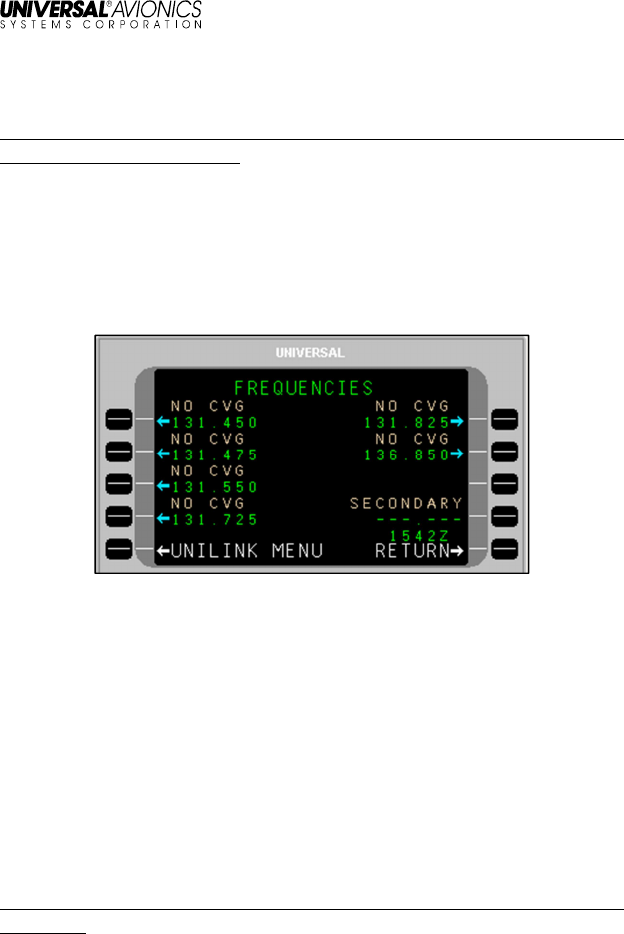
UniLink UL-800/801 FANS
SCN 30.X
Operator’s Manual
86 23-20-06.02
December 2011
FREQUENCIES
Menu Navigation: UNILINK MENU > COMM STATUS > COMM CONTROL >
VHF DATA > FREQUENCIES
The FREQUENCIES page is accessed by selecting the
FREQUENCIES, LSK [3R] on the VHF DATA page. The
FREQUENCIES page displays the primary frequency table and a field
for secondary frequency selection. Normal frequency selection is
controlled automatically by UniLink management logic and user
intervention is not required.
If the UniLink Geographic Database indicates that a DSP has
coverage on a particular frequency at the aircraft’s current location,
the DSP’s name will be displayed above the frequency (ARINC, SITA,
AVICOM, or MULTIPLE). Otherwise NO CVG (No Coverage) will
display.
LSKs allow manual selection of a primary frequency. The <*> icon
indicates the frequency that is currently tuned. The secondary
frequency may be manually entered or uplinked from the ground. Any
entry in the range of 118.000 through 136.975 will be accepted. Only
one frequency, primary or secondary, can be selected at a time.
TEL DATA
Menu Navigation: UNILINK MENU > COMM STATUS > COMM CONTROL >
TEL DATA
The TEL DATA page is available if an air phone is configured. The
TEL DATA page displays the DSP configured telephone number and
also allows manual override with a different number.
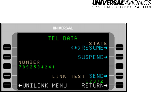
UniLink UL-800/801 FANS
SCN 30.X
Operator’s Manual
23-20-06.02 87
December 2011
To override the configured telephone number, press NUMBER, LSK
[3L]. This highlights the NUMBER field and allows the displayed
number to be edited or a new number to be entered. An entry of up to
19 digits is acceptable. The new entry will remain active until the
system is restarted, or the number may be restored to the configured
value by pressing the [BACK], then [ENTER] keys. From the
CDU/MCDU keyboard enter P for pause, L for #, or A for *.
Contact your DSP for the appropriate telephone number.
When the SUSPEND option is selected, telephone communication is
suspended and no datalink messages can be sent via telephony.
When RESUME is selected, the telephone can be used for sending
messages. The SUSPEND option is automatically selected if there
have been excessive unsuccessful attempts at sending messages via
telephony to the ground. Any manual selection will override any
automatically set condition. A <*> indicates the current state.
STATE
• RESUME: When selected, <*> will display. This allows the
TEL system to resume operation.
• SUSPEND: When selected, <*> will display. This suspends the
system. While suspended, no TEL transmissions will be
permitted by UniLink and no TEL uplink messages will be
processed.
Telephone Link Test
This feature provides the operator the ability to test the telephone link
by sending a downlink over the telephone system and then displays
the link test status. Run the test by selecting
LINK TEST
SEND, LSK
[4R]. The state of the telephone link test will display on the line above.
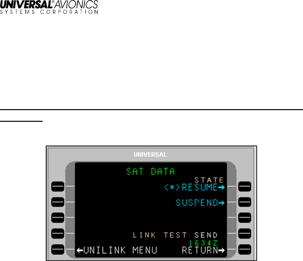
UniLink UL-800/801 FANS
SCN 30.X
Operator’s Manual
88 23-20-06.02
December 2011
Once the test is complete, the telephone status is displayed on the
COMM STATUS page. The displayed status is described in the
COMM Status section of this manual.
SAT DATA
Menu Navigation: UNILINK MENU > COMM STATUS > COMM CONTROL >
SAT DATA
The SAT DATA page allows the user to send a SatCom link test.
SatCom Datalink Test
This feature provides the operator the ability to test the SatCom link
by sending a downlink over the SatCom system and then display the
link test status. Run the test by selecting LINK TEST SEND, LSK [4R].
While the test is running, the state of the SatCom link test is displayed
on the line above.
Once the test is complete, the SatCom status is displayed on the
COMM STATUS page. The displayed status is described in the
COMM Status section of this manual.
STATE
• RESUME: When selected, <*> will display. This allows the
SAT system to resume operation.
• SUSPEND: When selected, <*> will display. This suspends the
SAT system. While suspended, no SAT transmissions will be
permitted by UniLink and no VHF uplink messages will be
processed.