3 Elite Join APOLLO11282004 Industrial Radio Remote Control User Manual
3-Elite Join Industrial Pte Ltd. Industrial Radio Remote Control Users Manual
Users Manual

Nov 2004
Industrial
Radio Remote Controlle
r
OPERATION
GUIDE
Our duty is ensure your safety, so you can rely on an excellent device
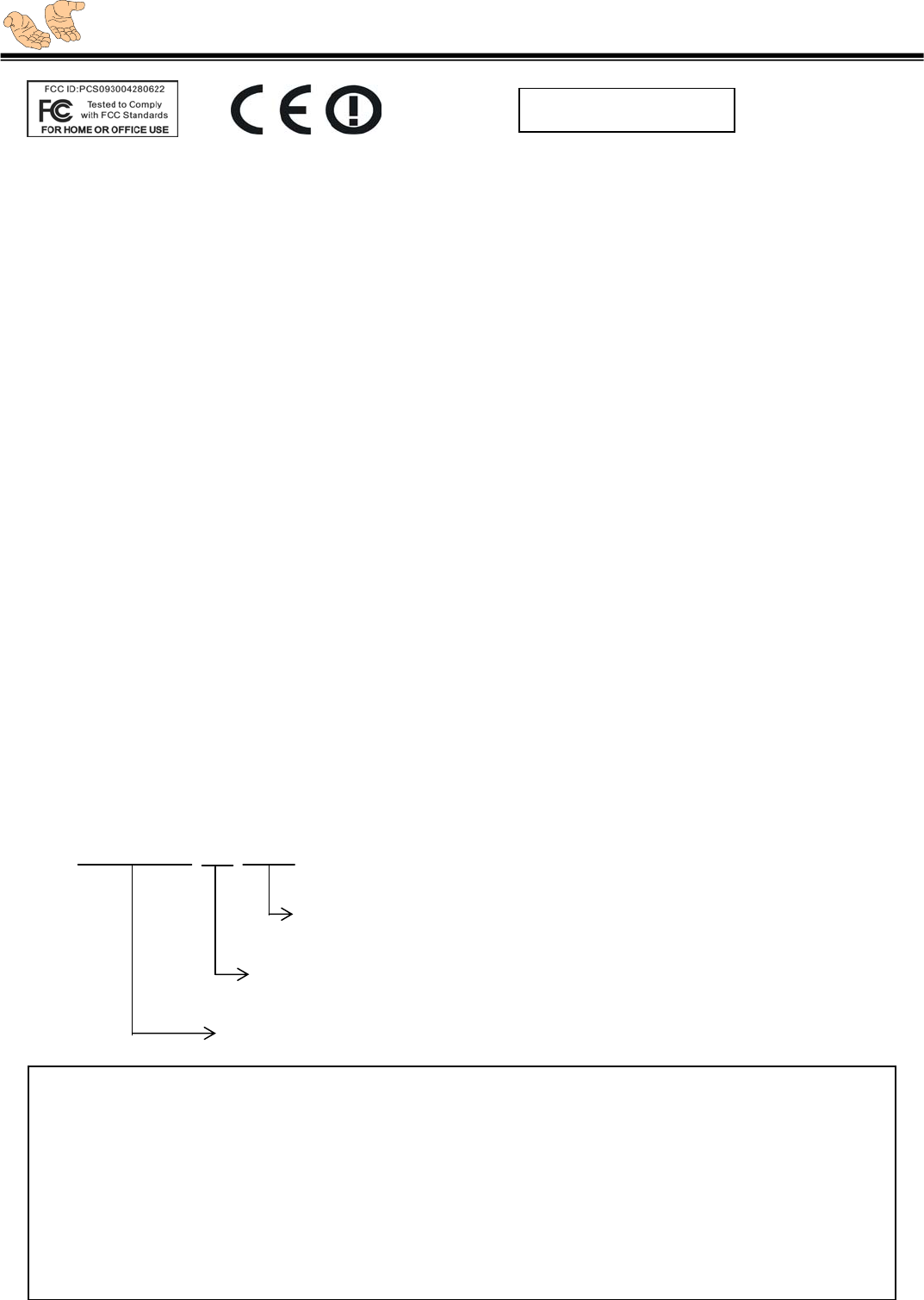
Note: The device complies with part 15 of FCC Rules. Operation is subject to the following two
conditions: (1) This device may not cause harmful interference , and (2) This device must not
accept any interference received, including interference that may cause undesired operation.
To comply with the FCC RF exposure compliance requirements, this device and its antenna
must not be co-located or operating to conjunction with any other antenna or transmitter.
The changes or modifications not expressly approved by the party responsible for compliance
could void the user's authority to operate the equipment.
TABLE OF CONTENTS
INTRODUCTION.......................................................................................................................................3
MODEL OPTIONS..................................................................................................................... 3
TECHNICAL SPECIFICATIONS .................................................................................................... 4
HOW TO INSTALL..................................................................................................................... 4
OPERATION STEPS.................................................................................................................. 5
FUNCTION SETTING................................................................................................................. 6
FUNCTION SWITCH FOR MULTI-HOIST ....................................................................................... 8
AUTO SHUT DOWN & AUTO SLEEP MODE.................................................................................. 9
STATUS INDICATOR ................................................................................................................. 9
PRECAUTION .......................................................................................................................... 10
ID LABEL ................................................................................................................................11
SPARE PARTS PHOTO ............................................................................................................. 11
SPARE PARTS LIST ................................................................................................................. 12
TROUBLE SHOOTING ............................................................................................................... 13
TRANSMITTER & RECEIVER DIMENSION..................................................................................... 17
WIRING DIAGRAMS.................................................................................................................. 18
WARRANTY PERIOD ................................................................................................................
APOLLO C1-6PB
6 Push Buttons, we offer 4/6/8/10/12 push buttons
C for Crane/Hoist used, 1 for single step,
2 for double steps, 3 for triple steps
Model
English Version

Our duty is ensure your safety, so you can rely on an excellent device
Introduction ☺
To satisfy various requests in remote controller, we are now finally researched a high quality,
industrial grade remote controller --- APOLLO system. Provided 8 push buttons, further
on you can decide if taking with reserved functions or not, and really feel the convenience!
APOLLO system, a reliable, durable remote controller, which can be instead of the original wired
control when the environment is too dangerous, something as electroplate field, steel factory, or the
field temperature is too high. Of course, it can also raising the producing efficiency!
Except the dust / water / oil proof casing, APOLLO can even resist strong shock, or the extreme
weather. Our professionalism surpass the original design, improved possible faults, the section
assembled push button parts save lots of pennies from unnecessary spend, which can also easily
up-grade to different models.
Your equipment does not have to adapt the remote controller, but it can really become an accessory!
Once the transmitter housing has to be renewed, you can just exchanging the damaged section, but
not the whole one. Only the reasonable spend can be accepted, in this point, we have considered
thoroughly in APOLLO system.
Take instant fix holder, APOLLO receiver makes installation steps much faster and easier. The
internal diagram / components scheme are hundred percent precision but not complex, easy to
understand and repair, specially save time in periodic maintenance. Components have been placed
into a tough control box, protection ups to IP65, contains dust / water / oil and ultraviolet, light weight,
easy carry on, save energy and time in device installation.
Model Option ☺
Model No. description
ONE STEP:
C1-4PB 4 pushbuttons, w/ EMS stop button
C1-6PB 6 pushbuttons, w/ EMS stop button
C1-8PB 8 pushbuttons, w/ EMS stop button
C1-8PB/AB 8 pushbuttons , A/B hoist use, w/ EMS stop button
C211 1st line two steps, 2nd, 3rd one step, w/ EMS stop button
C1-10PB 10 pushbuttons, w/ EMS stop button
C1-12PB 12 pushbuttons, w/ EMS stop button
TWO STEPS:
C2-4PB 4 pushbuttons, w/ EMS stop button
C2-6PB 6 pushbuttons, w/ EMS stop button
C2-8PB 8 pushbuttons, w/ EMS stop button
C2-8PB/AB 8 pushbuttons , A/B hoist use, w/ EMS stop button
C2-8PB/AL 8 pushbuttons, alarm & light, w/ EMS stop button
C2-10PB 10 pushbuttons, w/ EMS stop button
C2-12PB 12 pushbuttons, w/ EMS stop button
※ 3 steps are available on demand.

Our duty is ensure your safety, so you can rely on an excellent device
Transmitter
Technical Specifications ☺
Take dual-security design, equipment protected thoroughly, every output will automatically break
when CPU out of work.
Take common mode non-earth ground EMI noise-rejection circuit, which can against receiver
malfunction occurred by operator’s error connection, also releasing the installation complex.
Frequency range:
300 MHz ( 20 channels ) – for Asian.
433 MHz ( 20 channels ) – for American
868 MHz ( 20 channels ) –for Europe
Channel spacing: 50KHz , 60KHz
Transmitting power: < 10mW ( 10dBm )
Antenna: Internal type, impedance as 50Ω
Security codes: 256 sets
Operation temperature: 0°C ~ +70°C
Enclosure: IP65
Source voltage: 4xAA ( 1.5V )alkaline batteries
or nickel rechargeable batteries
Consumption: < 7mA
Size: 217×70×49 mm
Weight: 515g
Frequency range:
300 MHz ( 20 channels ) – for Asian
433 MHz ( 20 channels ) – for American use.
868 MHz ( 20 channels ) – for Europe use.
Channel spacing: 50KHz , 60KHz
Antenna: Internal type, impedance as 50Ω
Relay: 5A, 250V, AC
Operation temperature: -10°C ~ +70°C
Enclosure: IP65
Source voltage: 220V AC, 50 / 60Hz (STD)
Consumption: < 12W
Size: 250×120×75 mm
Weight: 1080g
How to install ☺
It would be very easy to install APOLLO receiver, the necessary tools are as following:
Long nose pliers diagonal cutting pliers cross head screwdriver
Hexagonal head wrench multimeter Electric drill Cable and feeder
Steps:
(a) Ensure the original wired control of crane is correct.
(b) Ensure shut down the main power source of crane before installation.
(c) Mount in a firmed site where the receiver can be seen easily by operator.
(d) Keep away the mounted site from motors, relays, cables, high voltage wiring and devices, or the
protrusion of building where crane moves. Select a firmed site without metal shielding around.
(e) Do not install the other same channel remote controller within 50 meters.
(f) Ensure the wiring layout correctly and safely.
(g) Test each motion / function after installation, ensure transmitter output have the same motion as
the original wired control.
Receiver
5
Our duty is ensure your safety, so you can rely on an excellent device
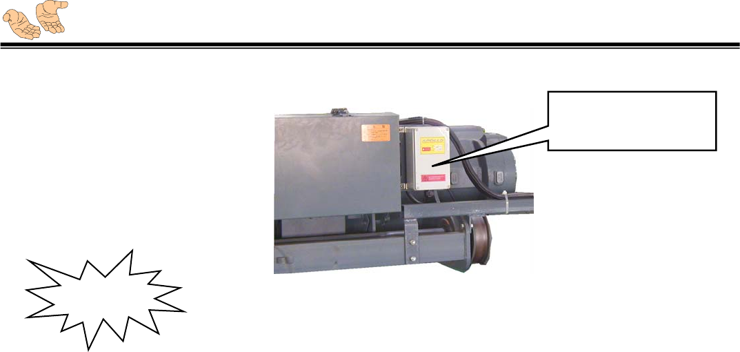
(h) Fix the wired pendant in safe position.
( fig. 1 ) ( example for fix / install receiver )
(a) Ensure the output contact as Main / A / B/ C / D / E/ F / G / H can not over 5A ( see
Wiring diagram after page 18 ).
(b) Please double check exactly the wiring layout after receiver’s installation, then turn the
power on.
(c) Please mount the receiver away from INVERTER, MOTOR and connected CABLE at least
3M to avoid interference happened
Operation steps ☺
How to start up the Apollo device:
1. Power on receiver.
2. Insert the transmitter power-on key and turn on the “ mushroom “ EMS push button.
3. Press any button and release to start-up receiver.
How to turn off the APOLLO device:
1. Press down the “ mushroom “ EMS push button ( At this moment, the internal Main contact
will be OFF ).
2. Pull out the transmitter power-on key.
3. Shut down the receiver.
Take 4pcs of 8mm tap screws,
screw tightly by electronic tools.
Mounted receiver in a
firmed site where the dual
color LED can be seen
caution
Our duty is ensure your safety, so you can rely on an excellent device
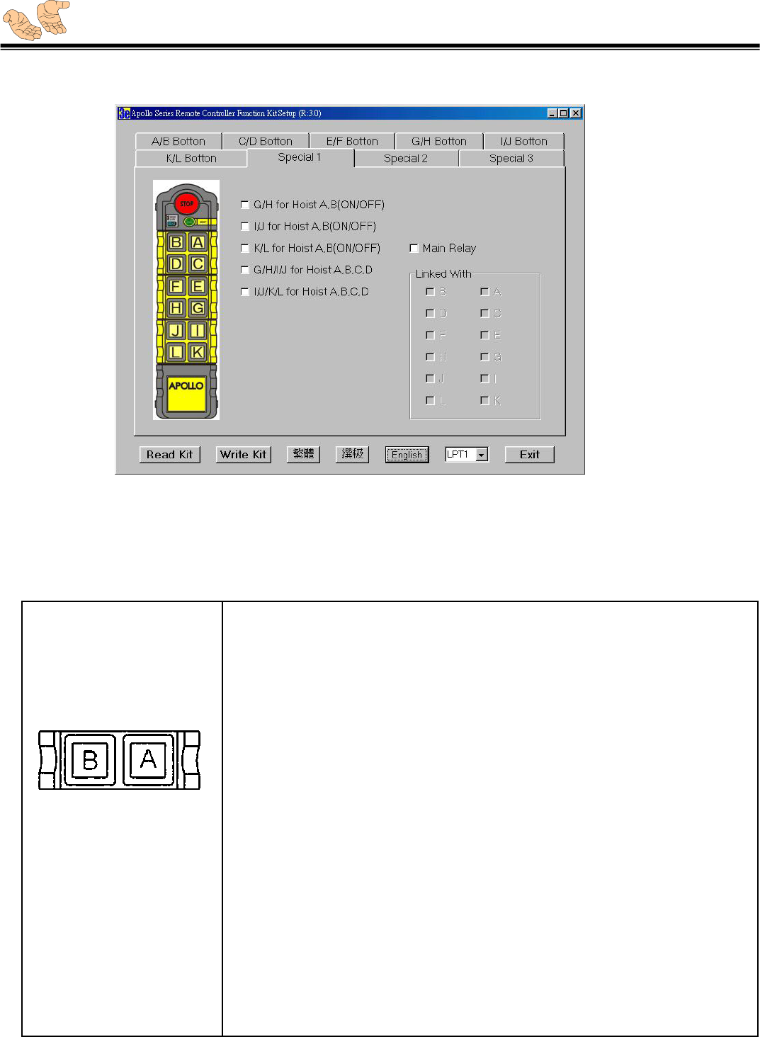
Function Setting : ☺
APOLLO system has complete setting software, which accepts different requests from customers. An
extra Function Kit may be needed for custom-made settings. ( See fig. 3 )
NOTE:
1) The function setting program is only operated under Window 98 Version.
2) The function kit has to extra plug in the JP3 ( DB9 pin ) on RECEIVER decoder ( relay ) board to
work the function setting.
3) Operation steps:
Clip ‘ start ‘ in Window 98
Select ‘ program ‘
Select ‘ Apollo ‘
Clip ‘ project – AP3 ‘ … set up program starts now
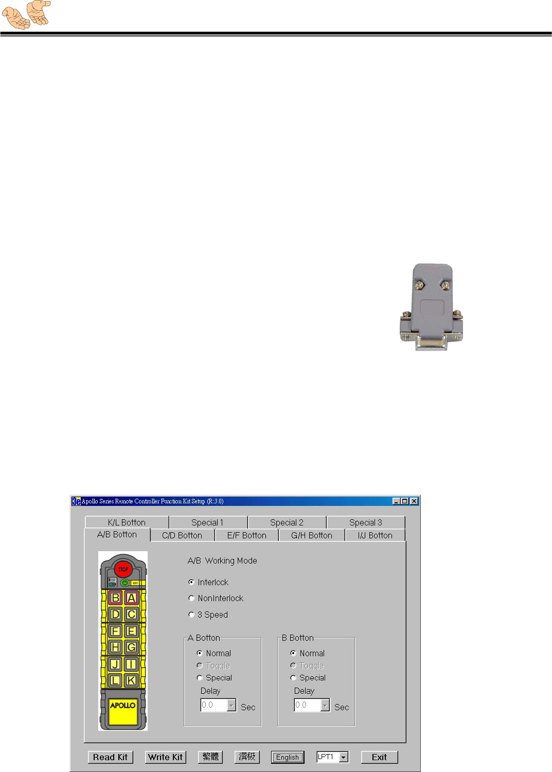
Every set of motion ( A/B, C/D, E/F, G/H, I/J, K/L ) all can be set function per customer’s
Need. Function setting options are as the following: ( See fig. 4 )
1) Interlock – ex-factory setting, when pressing A and B simultaneously, no function output , this is
for security reason.
2) Non-Interlock – For some occasions if the interlock is not necessary, just clip the ‘ non-interlock
‘ function.
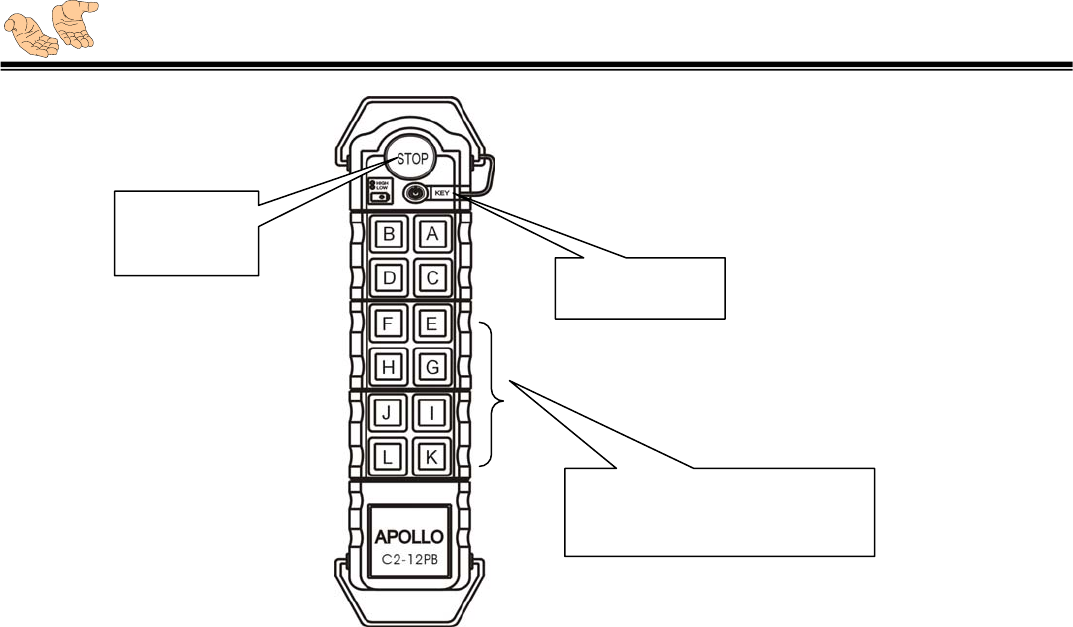
Special push button
E, G, I, K : Press to start-up
Power-on key
EMS-stop
p
ush butto
n
( fig. 2 )
Our duty is ensure your safety, so you can rely on an excellent device
3) 3 Speed – Pushbutton A and B will share their 2nd step relay to apply as the 2nd/3rd relay , i.e. A2
relay for 2nd step relay, B2 is for 3rd step replay.
The above pushbuttons can also be set independently for the following functions :
1) Normal – Normal function, press button and RELAY is on, release button is off.
2) Toggle – Press Firstly is ON, press again is OFF, please note the function is only for 1st speed ,
2nd speed is no such function.
3) Special – For some special application, such as for hoist 1st step and 2nd step is operated by two
different motor, the special function setting can be set to SWITCH the first motor and second motor.
And 1st step and 2nd step can set “ SWITCH DELAY TIME “ from 0.1~5 sec.
Or you may set two Trolleys ( Trolley A/B ) be operated by turns.
< using Toggle & Interlock setting >. ( see fig.4 )
4) Main Relay “ linked with “ – Main relay can be set to link with movement relay, this function
normally to apply on hydraulic system for oil pump use. ( see fig. 5 )
NOTE !!
Every set of motion ( A/B, C/D, E/F, G/H, I/J, K/L ) is interlocked to each other as ex-factory
Setting. That means to press up/down simultaneously , there is no function output for
security reason.
Function Kit ( fig. 3 )
( fig. 4 )
Our duty is ensure your safety, so you can rely on an excellent device
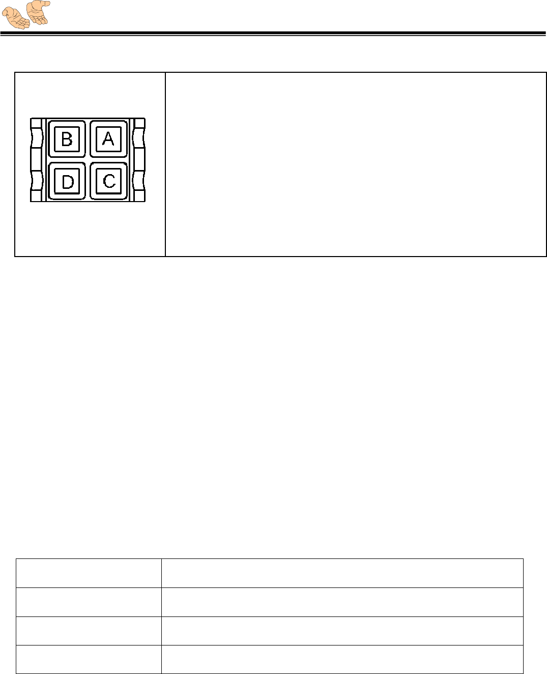
APOLLO Function Switch for Multi-Hoists:
Function: A, B or A+B hoist function switch.
Operation:
-press button A, then corresponded relay A will keep hold ( for hoist
A , relay B will release.
Press button B, then corresponded relay B will keep hold ( for hoist
B ), relay A will release.
Press button A and B together, then corresponded relay A and B
both will keep hold.
Position: K9, K10,
K11, K12,
K13, K14
( fig. 5 )
Our duty is ensure your safety, so you can rely on an excellent device
Function : A or B or C or D hoist function switch.
Operation:
Press button A or B or C or D, then corresponded relay A or B or C
or D will keep hold.
Position: K9, K10, K11, K12,
K11, K12, K13, K14
Auto Sleep Mode on Transmitter ☺
APOLLO transmitter could be set to sleep mode automatically, for higher security request,
shorten S3 ( could be found in encoder board ) would make transmitter into sleep mode
automatically after 5 minutes without operation. Simply return EMS push button to re-start
APOLLO Transmitter. ( setting already ex-works )
Auto shut down on Receiver ☺
APOLLO receiver could be set to shut down mode automatically, for higher security request,
shorten S2.4 would make receiver shut down automatically after 5 minutes without operation
( only setting ex-work on demand ).
Status Indicator of transmitter ☺
APOLLO transmitter has a dual-color indicator ( green*/red** ) to show various status as follows :
Green*: battery power is sufficient.
Red** : battery power low. Please re-new 4pcs of AA/UM-3 ( 1.5V ) alkaline batteries,
or nickel rechargeable batteries immediately.
Stand-by green indicator light is blinking 1 time every 4 sec. ( EMS is on )
operation green indicator light is blinking 1 time every 1 sec. ( EMS is on )
Sleep mode No indicator light is blinking ( EMS is on )
Power off No indicator light is blinking. ( EMS is off )

Our duty is ensure your safety, so you can rely on an excellent device
Status Indicator of Receiver ☺
APOLLO receiver has a dual-color indicator, GREEN for POWER, RED for SQ*.
And the dual-color indicator ( green/red ) also shows various status as follows:
SQ*: RF indicator light
Please NOTE that the SQ will NOT be lighted ( off ) when using its own transmitter , it means the
transmitted signal has been received by receiver and decoded correctly.
Main, A, B, C, D, E, F, G, H, I, J, K, L has its own indicator. When indicator is light, it means the relay
contact is ” On “, vice versa.
Precaution ☺
For safety consideration, complete training can only be offered / authorized to the operator.
Please read thoroughly the operation manual before using APOLLO system.
Regular maintenance / testing can extend the components’ life, malfunction will also be found
prior.
Before operating the transmitter please check by power-on key, see if the battery power is
sufficient. If not, please change a whole set of new battery. For a long term period without
operation we suggest you to take out of the batteries.
Do not try to change or move the internal components without authorization, please contact
your supplier, or the professional engineer who has the experience in industrial remote
controller for maintenance / repairs.
When the remote controller be struck by lightning, please stop operation and contact your
supplier as soon as possible.
Stand-by both green and red indicator light is ON.
operation green indicator light is ON, SQ ( red light ) is off.
Power off
both green and red light is OFF.
SQ Red light blinking slowly
( 1 time/sec. )
Malfunction may be incurred, please follow our trouble
shooting for repair or call service.
SQ Red light blinking fast
( 3 times/sec. )
the ID codes between transmitter and receiver is
switched different.
Please check the codes on both transmitters and
receivers, and switch them to the same positions..
Our duty is ensure your safety, so you can rely on an excellent device
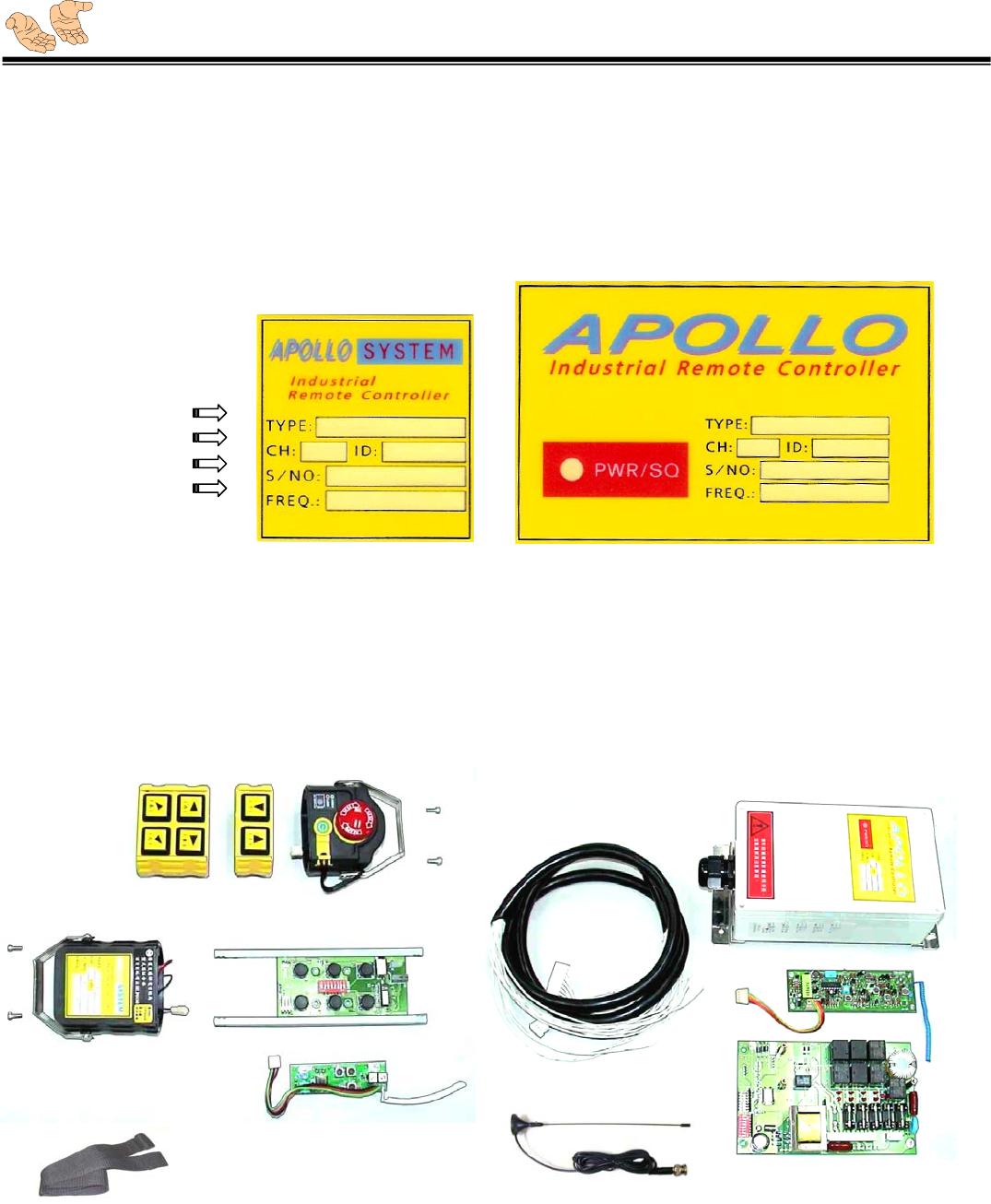
ID Label ☺
Every APOLLO system has its identification PC label, which defines the device’s type, ID, service
number, frequency and channel. For any inquiry please advise your supplier the service number for
a faster solution.
Spare Parts Photo ☺
( C1-6PB )
Type
Channel / ID
Service No.
Frequency
Transmitter ID label ( fig. 6 ) receiver ID label ( fig. 7 )
TOC
BOC
ED61
TFP
BOX.1
RFP
CAP16
NB
2TH
4TH
ANT
DD61
FCC ID: PCSAPOLLO11282004
Our duty is ensure your safety, so you can rely on an excellent device
Trouble shooting ☺
We have come across problems that are not associated with wireless remote control unit but
are crane/hoist or the device is subjected to control. Therefore it is essential that before
trouble shooting, the problem is identified to be relating the wireless remote control unit.
When malfunction occurs, please check APOLLO system per the following stating or the brief trouble
shooting chart step by step, or contact your supplier if device still can not be operated normally.
IF: Press any push button in transmitter but there has no output, the indicator does not
show…
Possibility: Check if the power-key has been inserted.
IF: The power-key has been inserted, but still has no output, the indicator also does not
show…
Possibility: Check if the EMS-stop push button has been pressed, if so, turn to “ on “.
Under the normal operation, EMS-stop push button shall not be pressed down.
IF: The EMS-stop push button has been turned to “ On “ , the power-key is inserted, but
still has no output, the indicator does not show either…
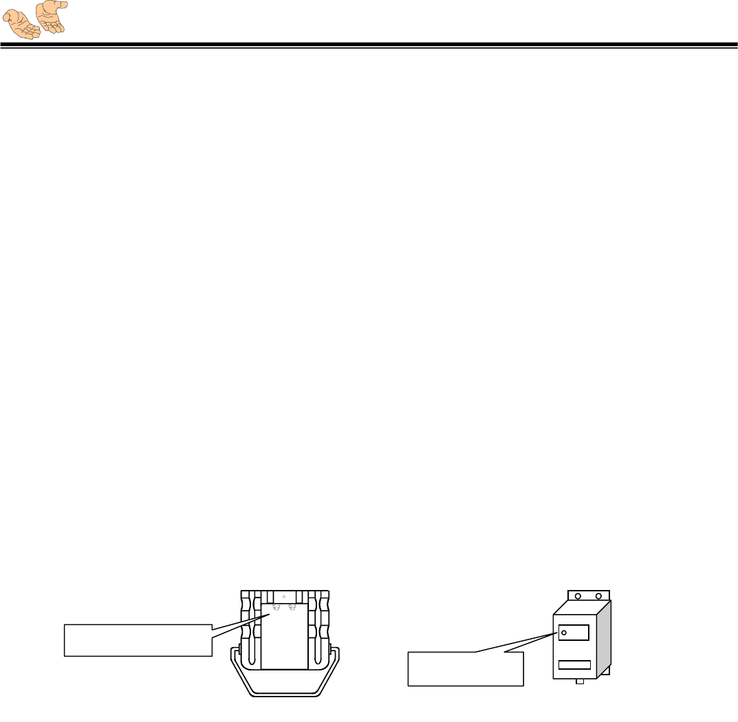
Possibility: Check if batteries have been inserted, or the power is sufficient. Renew a whole set
of batteries and place with correct poles directions, and keep these contacts clean ( see fig.8 ).
Press push button and see if indicator is responded to blink as 1 time every sec. If no, contact
your supplier immediately.
( fig. 8 )
IF: Crane moves by itself, can not be controlled by both APOLLO and the original
wired-control…
Possibility: Malfunction occurs in crane. Please repair the crane.
IF: Power on the receiver, but power SQ indicator ( see fig. 9 ) does not light…
Possibility: Power has not been sent to receiver. Check if F2* fuse is burn and renew a 0.5A
fuse.
IF: Replaced a new 0.5A fuse, but still be burn after power on…
Possibility: Receiver’s internal circuit has some problems. Please contact your supplier.
Keep these contacts clean
Power SQ indicator
( fig. 9 )
Our duty is ensure your safety, so you can rely on an excellent device
IF: F2* fuse has not been burn…
Possibility: The power input has some problems. Check if the input voltage is correct, if the
input voltage has no problem, find out the reason of abnormal voltage, or contact your supplier.
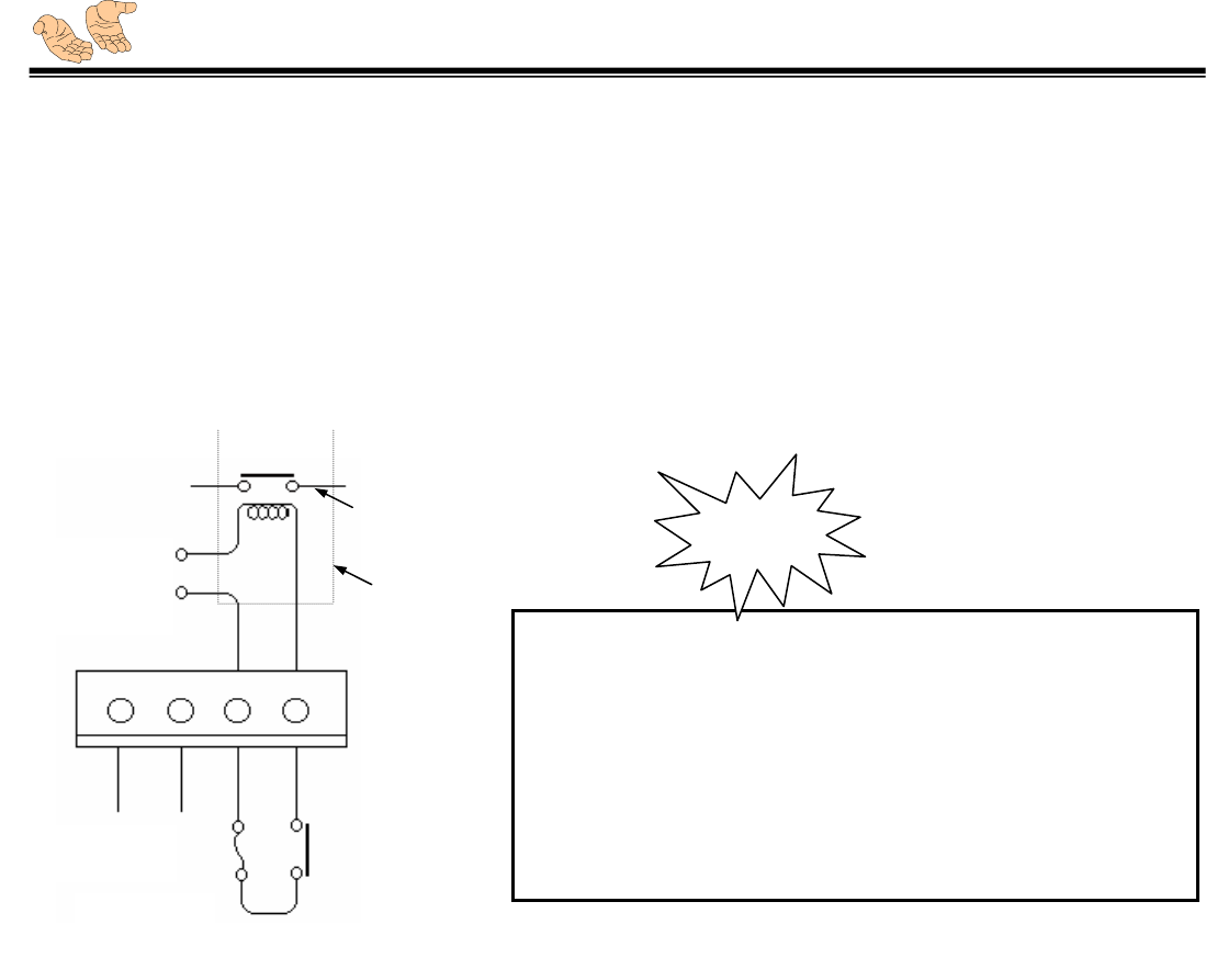
IF: The indicator of output Main contact has light, but its relay has no output…
Possibility: The fuse of Main contact, F1 is broken. Renew another 5A fuse.
F1*: power fuse ( 0.5A )
F2*: protection fuse ( 5A )
JP4
5A
Over 5
A
contact
Ext. contact relay
Every fuse be taken shall not over 5A, if larger output
contact current is requested, use another larger amp relay to
control its relay. ( see left diagram )
For example, if a fuse which over 5A be taken, it may cause
Main output contact be melt as overheat, and can not break,
this will cost much more in repairing.
Please do follow the trouble-shooting steps, or we shall have
no direct/indirect duty for any of your property loss!
Caution
( fig. 10 )
relay source
AC220
power in
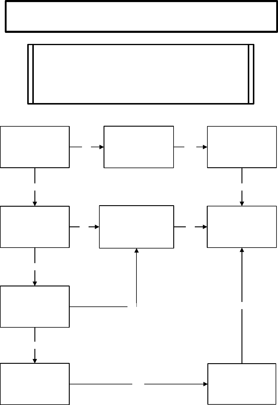
Apollo System- Transmitter ( TX )
General trouble shooting
If TX green indicator
light is blinking 1 time
every 4 sec. after
power-on
No light or in RED light
If working after re-new
batteries ( AA x 4pcs )
If indicator is blinking
fast when TX in
operation
( 1 time per 1 sec )
Pull out power-on key,
and check if TX works
after re-power
TX faulty
Call service
If SQ on RX is in
response
If operation is only
available in short
distance
If antenna of TX is in
bad shape or broken
NO YES
YES
NO
YES
NO
YES
YES
YES
NO
NO
NOTE:
Please make certain the following status before trouble shooting.
(1) The hoist/crane or device is subject to control works
(2) The TX outlook is in good condition without any leakage
(3) Receiver works.
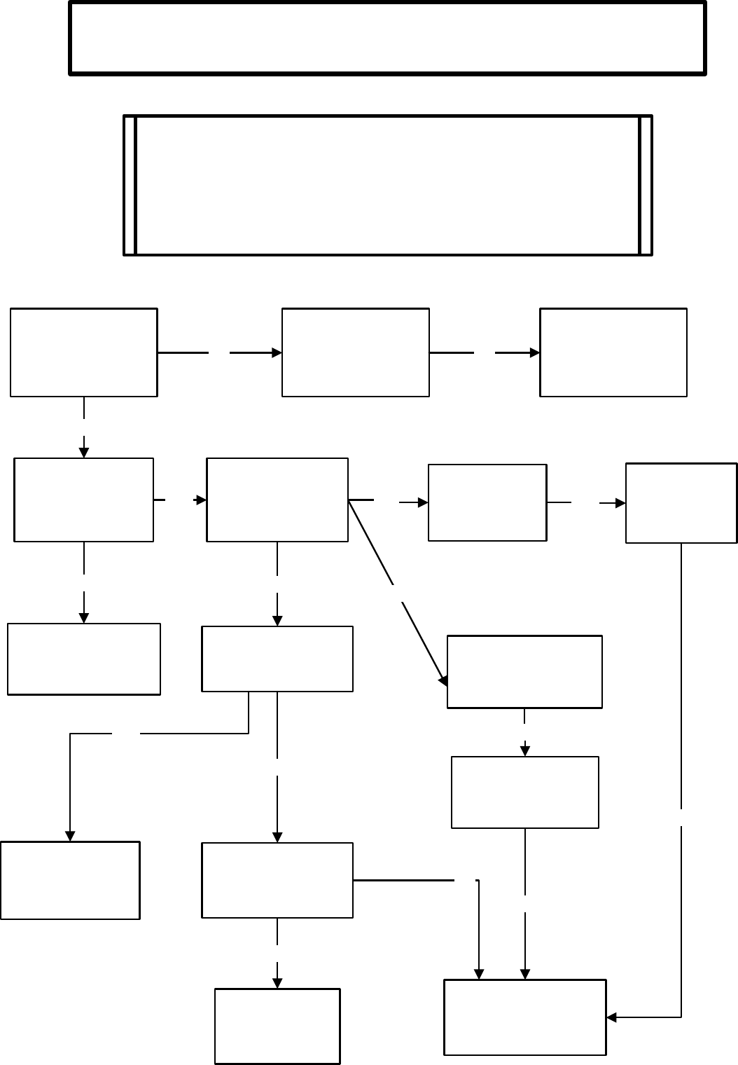
NOTE:
Please make certain the following status before trouble shooting:
(1) The crane or device being subject to control works.
(2) The RX outlook is in good condition without any leakage
(3) Transmitter works.
If power ( green ) and
SQ indicator ( red )
both are lighting
If cables is faulty
( open or short )
Check crane control
panel or call service
If SQ lighting when
TX is in operation
SQ red light
blinking slowly
( 1 time per sec. )
If RX works after
re-power
SQ red light fast
blinking
( 3 times per sec. )
If code ID switch
RX and TX
corresponds
If fuse is burn
If output cable is short
Receiver faulty
Call service
Replace cable
NO NO
NO
YES NO YES
YES
NO
YES
NO
YES
NO
NO
Re-new fuse
YES
RF on RX is in
malfunction.
Call service.
YES
If correspondent
relay is response
to the commands
from TX
Or NO
Apollo System- Receiver ( RX )
General trouble shooting
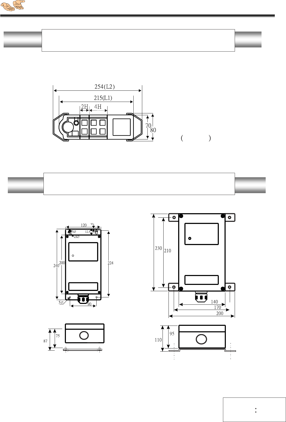
APOLLO Transmitter Dimension
L1 L2
4PB 188.5 227.5
6PB 215 254
8PB 240.5 279.5
10PB 267 306
12PB 292.5 331.5
2H 26.5
4H 52
12
Our duty is ensure your safety, so you can rely on an excellent device
IP65
Unit mm
APOLLO Box.1/Box.2 Receiver Dimension
Box.1 For :P700,C1-4PB,C1-6PB,C1-8PB,C2-4PB, C211
Box.2 For: C1-10PB,C1-12PB,C2-6PB,C2-8PB,C2-10PB,C2-12PB
Box.1: IP65
Box.2: IP67
13
Box.1 Box.2

Our duty is ensure your safety, so you can rely on an excellent device
Apollo System
Installation Wiring Diagrams
Remarks:
For standard models only
Custom-made is available on demand
Our duty is ensure your safety, so you can rely on an excellent device
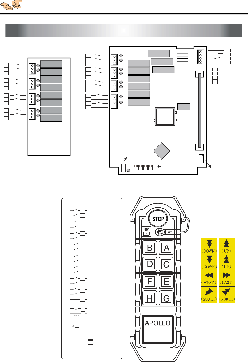
APOLLO C2-8PB Installation Wiring Diagram
K14 CPU
K13 Main
K1 A
K2 B
K3 C
K4 D
K5 E
K6 F
K7 G
K8 H
ST
1 step in
ST
1 step in
ST
1 step in
ST
1 step in
ST
1 step in
ST
1 step in
ST
1 step in
ST
1 step in
ND
L1 2 step in A
ND
L2 2 step in B
ND
L3 2 step in C
ND
L4 2 step in D
ND
L5 2 step in E
ND
L6 2 step in F
ND
L7 2 step in G
ND
L8 2 step in H
F1 0.5A Power Fuse
F2 5A Main Fuse
C2-8PB
ST
1 step in A
ST
1 step in B
ST
1 step in C
ST
1 step in D
ST
1 step in E
ST
1 step in F
ST
1 step in G
ST
1 step in H
Common
EMS-Stop
APOLLO C2-8PB
ND
2 step in A
ND
2 step in B
ND
2 step in C
ND
2 step in D
ND
2 step in E
ND
2 step in F
ND
2 step in G
ND
2 step in H
Common
1
2
3
4
5
6
7
8
11
12
13
14
15
16
17
21
18
22
23
24
25
Power
87654321
CPU
ON
F1
K14
K1
K2
COMMON
K3
K4
COMMON
JP11
K5
K6
COMMON
K8
COMMON
K13
COMMON FUSE 5A
K7
COMMON
POWER
POWER FUSE 0.5A
K14
CPU
JP12
JP13
JP14
JP5
F2
K3
K4
K5
K6
K7
K8
K2
K1
K13
L1
L2
L3
L4
L5
L6
L7
L8
L1
COMMON
JP21
L2
L3
COMMON
Jp22
L4
L5
COMMON
Jp23
L6
L7
COMMON
Jp24
L8
AC-110V
AC-220V
AC-380V
AC-415V
1
2
21
3
4
21
5
6
21
7
8
21
21
21
18
17
21
16
15
21
14
13
21
12
11
25
24
23
22
2nd step relay board
Connect w/LED
Connect w/HF
decoder & relay board (REV:3.21)
ID codes
HF board
HF board
Button-legend
(custom-made on demand)
AC-110V
AC-220V
AC-380V
AC-415V
FUSE 0.5A

Our duty is ensure your safety, so you can rely on an excellent device
Limited One Year Warranty
The equipment is warranted for one year from date of purchase against defects in materials or
workmanship provided it was purchased from 3-Elite or authorized dealer.
This warranty does not cover equipment which has been abused or damaged by careless
handling or shipping, OR damaged by nature disaster such as earthquake, typhoon …etc.
The careless handling including self-change components, antenna, voltage; or circuits, and
switches increased would be deemed as end of warranty, user should cover the repairing fee.
Should any defect develop, we will, at our option, repair or replace any defective parts without
charge for either parts or labor. If we cannot correct the defect in your equipment, we will
replace it at no charge with a new one. We will pay for the cost of returning your merchandise
to you.
This warranty applies only to items returned to us, shipping costs prepaid, within one year
from the date of purchase.