3M Traffic Safety Systems 1000 3M Compact RFID Reader User Manual Users manual
3M Traffic Safety Systems 3M Compact RFID Reader Users manual
Users manual
3M Compact RFID Reader
1000
User’s Guide

ii 3M Compact RFID Reader 1000 User’s Guide

3M Compact RFID Reader 1000 User’s Guide
iii
3M Compact RFID Reader 1000
User Guide
V1.2.5
September 16, 2014
© 3M 2014. All Rights Reserved.
3M is a trademark of 3M. All other trademarks are the property of their respective owners. Specifications are subject to change without
notice.
Disclaimer and Limitation of Liability
The content of this manual is for information use only and is subject to change without notice. 3M assumes no responsibility or liability for
any errors or inaccuracies that may appear in this publication. No part of this manual may be reproduced in any form or by any means,
electronic, mechanical, recording, or otherwise, without the prior written permission of 3M.
3M products are not designed, intended, authorized or warranted to be suitable for life support applications or any other life critical
applications which could involve potential risk of death, personal injury, property damage, or environmental damage.
FCC Notice
This equipment has been tested and found to comply with the limits for a Class A digital device, pursuant to Part 15 of the FCC Rules.
These limits are designed to provide reasonable protection against harmful interference when the equipment is operated in a commercial
environment. This equipment generates, uses, and can radiate radio frequency energy and, if not installed and used in accordance with the
instruction manual, may cause harmful interference to radio communications. Operation of this equipment in a residential area is likely to
cause harmful interference in which case the user will be required to correct the interference at his own expense.
Le présent appareil est conforme aux CNR d'Industrie Canada applicables aux appareils radio exempts de licence. L'exploitation est
autorisée aux deux conditions suivantes : (1) l'appareil ne doit pas produire de brouillage, et (2) l'utilisateur de l'appareil doit accepter tout
brouillage radioélectrique subi, même si le brouillage est susceptible d'en compromettre le fonctionnement.
Canadian Note: CAN ICES-3(A)/NMB-3(A)
FCC Radiation Exposure Statement
The antennas used for this transmitter must be installed to provide a separation distance of at least 1 meter from all persons and must not
be co-located or operating in conjunction with any other antenna or transmitter. This device complies with Health Canada’s Safety Code.
The installer of this device should ensure that RF radiation is not emitted in excess of the Health Canada’s requirement. Information can be
obtained at
http://www.hc-sc.gc.ca/ewh-semt/pubs/radiation/radio_guide-lignes_direct/index-eng.php
Cet appareil est conforme avec Santé Canada Code de sécurité 6. Le programme d’installation de cet appareil doit s’assurer que les
rayonnements RF n’est pas émis au-delà de I’exigence de Santé Canada. Les informations peuvent être obtenues:
http://www.hc-sc.gc.ca/ewh-semt/pubs/radiation/radio_guide-lignes_direct/index-fra.php
NOTICE
The 3M Compact RFID Reader 1000 is designed to meet the regulatory requirements in those jurisdictions in which it is offered. Changes or
modifications not expressly approved by 3M for compliance could void the user's authority to operate the equipment.

iv 3M Compact RFID Reader 1000 User’s Guide
CE Notice
3M hereby declares that this device is in compliance with the essential requirements of the European R&TTE Directive 1999/5/EC.
Patent: 3M.com/patents
Product ID: RFID1000
3M Traffic Safety and Security Systems
Motor Vehicle Safety Systems
Building 3
11705 Research Blvd
Austin, TX 78759
Web: www.3m.com

Preface
3M Compact RFID Reader 1000 User’s Guide
v
Preface
Intended audience
This document is intended for those who wish to setup and operate the 3M
Compact RFID Reader 1000. Before attempting to install, configure, and
operate this product, you should be familiar with the following:
Windows-based software installation and operation
Device communication parameters including Ethernet, serial, and digital
input/output control
RFID reader configuration including antenna placement
What’s in this guide
The information in this guide is presented as follows:
Chapter 1 - Reader Overview:This chapter provides a brief overview of the
3M Compact RFID Reader 1000 hardware and software.
Chapter 2 – Safety Information – This chapter provides important safety
information about the 3M Compact RFID Reader 1000. All users must read
this section before installing or operating this reader.
Chapter 3 - Reader Equipment Installation – This chapter describes how to
mechanically and electrically install the reader.
Chapter 4 - Reader Startup Tool (RST) Software Installation – This chapter
describes how to install the Microsoft Windows RST application.
Chapter 5 - Reader Operation – This chapter describes how to initially test a
reader and how to operate deployed readers.
Chapter 6 - Reader Startup Tool (RST) – This chapter describes the RST and
the functions you can perform with this Microsoft Windows application.
Chapter 7 - Reader Configuration Tool (RCT) – This chapter describes the
RCT and the functions you can perform with this embedded application.
Chapter 8 - Configuring Digital Inputs and Outputs – This chapter describes
how to setup the reader’s digital inputs and outputs.
Chapter 9 - Specifications – This chapter detailed mechanical, electrical,
and environmental specifications for the 3M Compact RFID Reader 1000.
Appendix A - Digital Input/Output Interface Module – This appendix provides
information for installing and using the external digital interface module.
Appendix B - USB Port Setup – This appendix includes USB port driver
installation and setup procedures for both Windows XP and Windows 7.
Appendix C - Disposal of the 3M Compact RFID Reader 1000 – This
appendix provides instruction for battery removal and reader disposal.
Preface
vi 3M Compact RFID Reader 1000 User’s Guide
What’s New in this Version
Version 1.2.1 of this User’s Guide updates safety information and corrects
minor errors.
Conventions used in this manual
The following conventions are used in this manual:
Bold courier font indicates code entered by the user
(values) within parentheses indicate parameters
(values) in italics indicate user defined variables.
<n> indicates a variable number used in a function that can apply to
several different devices such as antennas or I/O ports.
WARNING: Indicates a hazardous situation which, if not avoided, could result in
death or serious injury.
CAUTION: Indicates a hazardous situation which, if not avoided, could result in minor
or moderate injury or property damage.
ATTENTION: This yellow symbol indicates that the device is susceptible to
Electro Static Discharge and appropriate precautions must be
taken to avoid equipment damage.
NOTICE NOTICE advises the reader that a condition can be created by a particular action that
can cause equipment damage or result in equipment operation that violates regulatory
requirements.
NOTES
Important information
and other tips are
presented in light
blue boxes to the left
of the applicable
section.
Preface
3M Compact RFID Reader 1000 User’s Guide
vii
Product Use Statement
Product Use: Many factors beyond 3M’s control and uniquely within user’s
knowledge and control can affect the use and performance of a 3M product
in a particular application Given the variety of factors that can affect the
use and performance of a 3M product, user is solely responsible for
evaluating the 3M product and determining whether it is fit for a particular
purpose and suitable for user’s method of application.
Warranty, Limited Remedy, and Disclaimer: Unless a different warranty is
specifically stated on the applicable 3M product packaging, product
literature, terms of sale or software license agreement, 3M warrants that (i)
the 3M product will be free from substantial defects in material and
workmanship under normal use and service for one (1) year from the
original date of purchase, and (ii) for software products, for ninety (90) days
from the original date of purchase, the software will materially perform the
functions described in the accompanying documentation. 3M MAKES NO
OTHER WARRANTIES OR CONDITIONS, EXPRESS OR IMPLIED, INCLUDING,
BUT NOT LIMITED TO, ANY IMPLIED WARRANTY OR CONDITION OF
MERCHANTABILITY OR FITNESS FOR A PARTICULAR PURPOSE OR ANY
IMPLIED WARRANTY OR CONDITION ARISING OUT OF A COURSE OF
DEALING, CUSTOM OR USAGE OF TRADE. If the 3M product does not
conform to this warranty, then the sole and exclusive remedy is, at 3M’s
option, repair or replacement of the 3M product.
Limitation of Liability: Except where prohibited by law, 3M will not be liable
for any loss or damage arising from the 3M product, whether direct,
indirect, special, incidental or consequential, regardless of the legal theory
asserted, including warranty, contract, negligence or strict liability.

Contents
viii 3M Compact RFID Reader 1000 User’s Guide
Table of Contents
1Reader Overview ................................................................................................................................... 1
1.1.Reader Hardware ................................................................................................................................. 1
1.2.Reader Software ................................................................................................................................... 3
2Safety Information ............................................................................................................................... 4
2.1.Intended Use ......................................................................................................................................... 4
2.2.Explanation of Signal Word Consequences ...................................................................................... 4
2.3.Attendant Warnings ............................................................................................................................. 4
2.4.Installation and Service Technician Warnings and Cautions ........................................................ 5
2.4.1.Reader System Related ............................................................................................................. 5
2.4.2.3M Headlamp RFID Tag .......................................................................................................... 7
2.5.RF Safety ................................................................................................................................................ 7
2.6.Electrostatic Discharge ........................................................................................................................ 7
2.7.Regulatory Compliance ....................................................................................................................... 8
2.7.1.FCC Notice ............................................................................................................................... 8
2.7.2.NCC Notice, Taiwan ................................................................................................................. 8
2.8.Power/Data Cable Size ....................................................................................................................... 8
3Reader Equipment Installation .......................................................................................................... 9
3.1.Mechanical Installation ....................................................................................................................... 9
3.1.1.Mounting the Reader ................................................................................................................. 9
3.1.2.Mounting the Antennas ........................................................................................................... 10
3.2.Electrical Installation ........................................................................................................................ 11
3.2.1.Connecting the Serial Port ...................................................................................................... 12
3.2.2.Connecting the USB Ports ...................................................................................................... 12
3.2.3.Connecting and Configuring the Ethernet Port ....................................................................... 12
3.2.4.Connecting the Antennas ........................................................................................................ 13
3.2.5.Connecting Digital Inputs/Outputs ......................................................................................... 13
3.2.6.Connecting the Power ............................................................................................................. 14
Contents
3M Compact RFID Reader
1000
User’s Guide
ix
4Reader Startup Tool (RST) Software Installation ......................................................................... 15
4.1.Installing RST Software .................................................................................................................... 15
4.2.Windows 7 Setup ............................................................................................................................... 17
4.3.Reader Startup ................................................................................................................................... 18
4.4.Initial Reader Setup .......................................................................................................................... 19
5Reader Operation .............................................................................................................................. 24
5.1.Basic Operation with RST ................................................................................................................. 24
5.2.Deployed Reader Operation with RCT ............................................................................................ 26
6Reader Startup Tool (RST) ............................................................................................................... 28
6.1.View Readers on the Network ......................................................................................................... 28
6.2.Configure Reader with the Setup Wizard ...................................................................................... 29
6.3.Customize Discovery Options .......................................................................................................... 30
6.4.View or Change the Reader’s Network Settings ........................................................................... 31
6.5.Reader Test Tool (RTT) ...................................................................................................................... 32
6.5.1.General Page ........................................................................................................................... 32
6.5.2.Tag Performance Page ............................................................................................................ 35
6.5.3.Tag Management Page ............................................................................................................ 37
6.5.4.Macros Page ............................................................................................................................ 38
6.5.5.Event Handling Page ............................................................................................................... 40
6.5.6.Antenna Settings Page ............................................................................................................. 41
6.6.Reader Diagnostics Tool (RDT) ........................................................................................................ 42
6.6.1.Channel Statistics .................................................................................................................... 42
6.6.2.Alarms ..................................................................................................................................... 43
6.6.3.Tag Report ............................................................................................................................... 44
6.6.4.Spectrum Analyzer .................................................................................................................. 45
6.6.5.Power Ramp Tool .................................................................................................................... 46
Contents
x
3M Compact RFID Reader 1000 User’s Guide
7Embedded Reader Configuration Tool (RCT) ................................................................................ 47
7.1.Basic Configuration ........................................................................................................................... 48
7.1.1.Configuration Page Header ..................................................................................................... 48
7.1.2.Manage Profiles ...................................................................................................................... 49
7.1.3.Set Tag Protocol ...................................................................................................................... 51
7.1.4.Setup Ethernet/LAN ................................................................................................................ 52
7.1.5.Setup Serial Port ...................................................................................................................... 53
7.1.6.Setup Digital Accessories ....................................................................................................... 54
7.1.7.Setup Antenna/Cables ............................................................................................................. 55
7.1.8.Set Regulatory Mode (Region) ............................................................................................... 57
7.1.9.Setup Summary ....................................................................................................................... 57
7.2.Advanced Functions .......................................................................................................................... 58
7.2.1.Firmware Management ........................................................................................................... 58
7.2.2.Import/Export Configuration .................................................................................................. 59
7.2.3.Command Line ........................................................................................................................ 61
7.3.Expert Configuration ......................................................................................................................... 62
7.3.1.Expert Configuration – Setup ................................................................................................. 62
7.3.2.Expert Configuration – Tag .................................................................................................... 63
7.3.3.Expert Configuration – Version .............................................................................................. 64
7.3.4.Expert Configuration – Information ....................................................................................... 65
7.3.5.Expert Configuration – Communication ................................................................................. 66
7.3.6.Expert Configuration – Antennas............................................................................................ 67
7.3.7.Expert Configuration – Digital I/O ......................................................................................... 68
7.3.8.Expert Configuration – Modem .............................................................................................. 69
7.4.User Application Management ........................................................................................................ 70
7.5.Change Operating Mode ................................................................................................................... 71
7.6.View Tags ............................................................................................................................................ 72
7.7.Check Reader Status ........................................................................................................................ 73
7.8.Review Logs ....................................................................................................................................... 75
Contents
3M Compact RFID Reader
1000
User’s Guide
x
i
8Configuring Digital Inputs and Outputs .......................................................................................... 76
8.1.Digital Inputs ...................................................................................................................................... 76
8.2.Digital Outputs ................................................................................................................................... 76
8.3.Low Latency Digital Input/Output Operation ................................................................................ 76
8.4.Digital I/O Monitoring and Control Scripts .................................................................................... 78
8.4.1.scan_trigger.py ........................................................................................................................ 78
8.4.2.scan_trigger_timer.py .............................................................................................................. 79
8.4.3.signal_read.py ......................................................................................................................... 79
8.4.4.signal_read_crc_error.py ......................................................................................................... 80
8.4.5.rf_mon.py ................................................................................................................................ 80
8.5.Digital Input Alarm Generation ....................................................................................................... 81
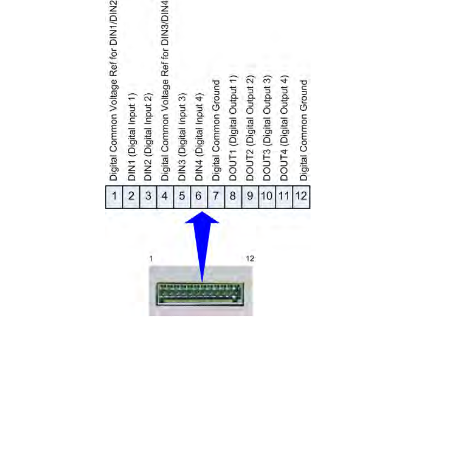
8.6.Digital I/O Hardware Connection .................................................................................................... 82
9Specifications ..................................................................................................................................... 83
9.1.1.Reader Specifications .............................................................................................................. 83
9.1.2.Environmental Specifications ................................................................................................. 84
9.1.3.AC/DC Power Adapter Specifications .................................................................................... 84
9.1.4.RS-232 Specifications ............................................................................................................. 84
9.1.5.Digital Input/Output Specifications ........................................................................................ 85
9.1.6.Ethernet LAN Specifications .................................................................................................. 85
9.1.7.3M Toll RFID Reader 1000 Antenna Specifications .............................................................. 86
ADigital Input/Output Interface Module........................................................................................... 87
A.1.Digital Inputs ........................................................................................................................... 88
A.2.Digital Outputs ........................................................................................................................ 88
A.3.Input Power and Voltage Regulator ........................................................................................ 88
A.4.Connecting External Switches and Indicators ......................................................................... 89
BUSB Port Setup .................................................................................................................................. 91
B.1.Windows XP Driver Installation and Setup ............................................................................ 91
B.2.Windows 7 Driver Installation and Setup ............................................................................... 97
CDisposal of the 3M Compact RFID Reader 1000 ....................................................................... 106
Contents
x
ii 3M Compact RFID Reader 1000 User’s Guide
This page intentionally left blank.
1 2 3 4 5 6 7 8 9 Reader Overview
3M Compact RFID Reader
1000
User’s Guide
1
1 Reader Overview
1.1. Reader Hardware
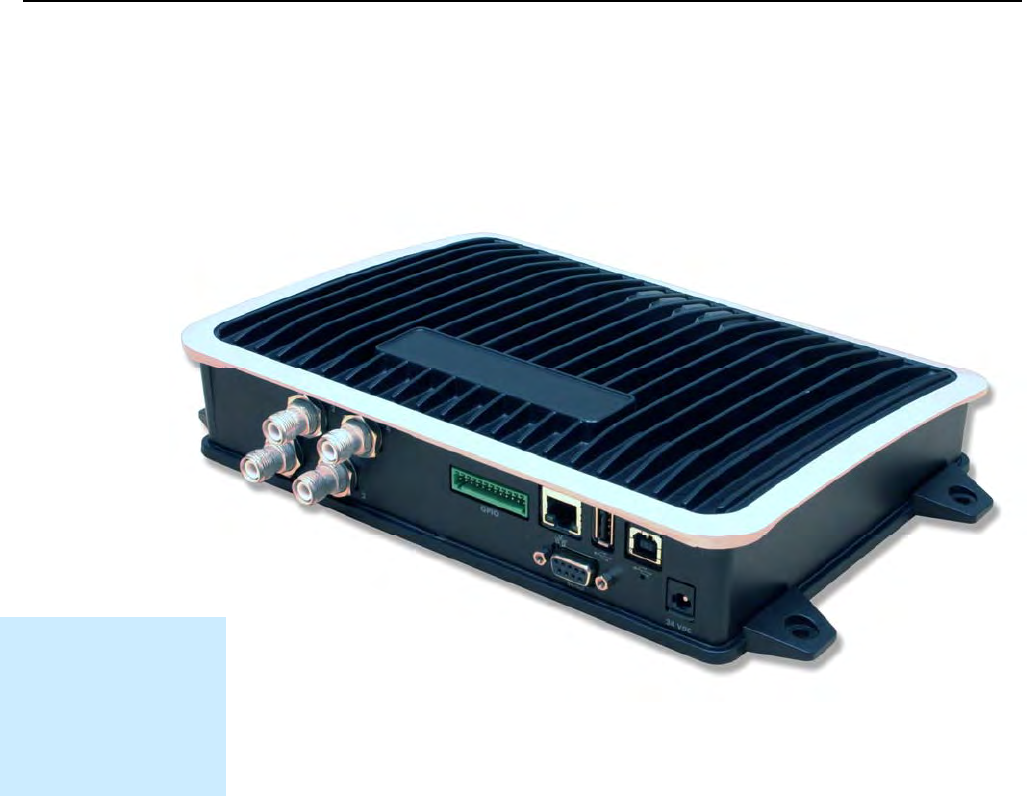
The 3M Compact RFID Reader 1000 is a multi-protocol, multi-regional Radio
Frequency Identification (RFID) System that operates in the 860 – 960 MHz
UHF band.
Figure 1 3M Compact RFID Reader 1000
As shown in Figure 1 and Figure 2, this high performance reader supports
up to four Tx/Rx antennas (4x1 monostatic or 2x2 bistatic) and is equipped
with RS-232, USB 2.0, and Ethernet interfaces. Discrete digital inputs and
outputs are also provided.
Installation Notice
Installation of the 3M
Compact RFID Reader
1000 is only to be
performed by trained,
3M approved
personnel.
1 2 3 4 5 6 7 8 9 Reader Overview
2 3M Compact RFID Reader 1000 User’s Guide
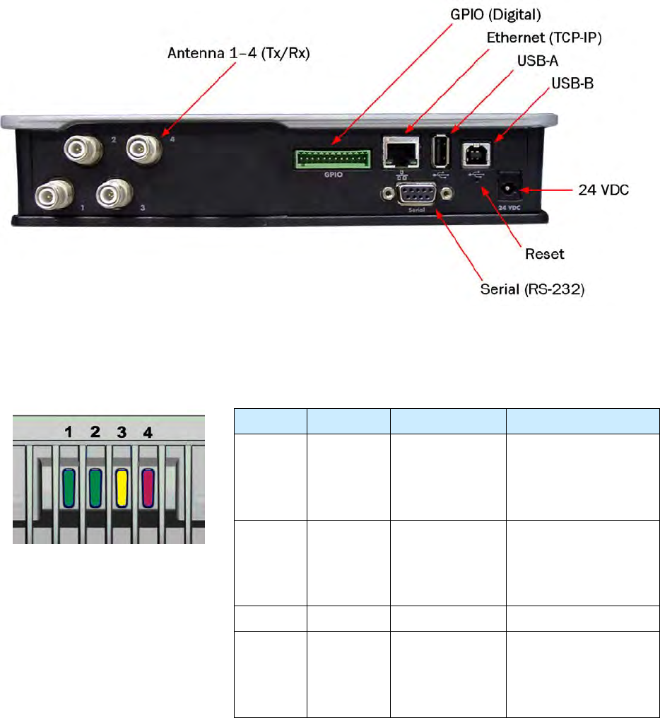
Figure 2 3M Compact RFID Reader 1000 Input/Output and Power Panel
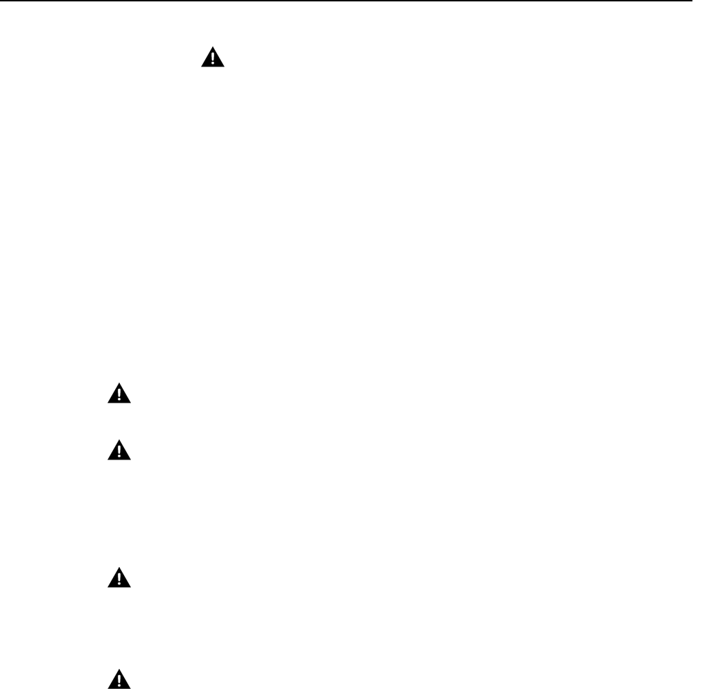
The 3M Compact RFID Reader 1000 is also equipped with four status
indicators located on the top of the enclosure. From left to right, these LEDs
provide indication for the following:
Number Indication Color/State Indication
1 Power Off
Amber
Amber-Flashing
Green
Power off
Boot loader executing
Linux initializing
Unit operational
2 Activity Off
Green
Green-Flash
Amber
RF Off
TX Active
Tag detect
Antenna check failed
3 User Amber User defined
4 Status Off
Amber
Green-Flash
Red
OK
Firmware update
GPIO activity
Fault
1 2 3 4 5 6 7 8 9 Reader Overview
3M Compact RFID Reader
1000
User’s Guide
3
1.2. Reader Software
The 3M Compact RFID Reader 1000 is shipped with two software
applications that you can use to configure and control the reader.
Reader Startup Tool (RST)
RST is a Microsoft Windows application you install on your computer. With
RST, you can view all readers on your network. After selecting a reader, you
can modify its communication, network, and operational parameters. You
can also read tags, review tag data, perform diagnostics, and upload new
software. This RST is primarily intended for initially configuring a reader
prior to deployment. After deployment, use the Embedded Reader
Configuration Tool (RCT). Detailed information on the RST is provided in
Chapter 5.
Embedded Reader Configuration Tool (RCT)
RCT is an embedded reader application that allows you to access your
readers across the internet. Enter the IP address of the reader into your web
browser and the RCT allows you to fully modify and operate the reader. With
the same functionality as the RST, this application allows you to modify the
reader’s communication, network, and operational parameters. You can
also read tags, review tag data, perform diagnostics, and upload new
software. This application is primarily intended for configuring and
managing deployed readers. Detailed information on the RCT is provided in
Chapter 6.
1 2 3 4 5 6 7 8 9 Safety Information
4 3M Compact RFID Reader 1000 User’s Guide
2 Safety Information
Please read, understand, and follow all safety information contained
in these instructions prior to the use of this RFID Interrogator/Reader
product. Retain these instructions for future reference.
2.1. Intended Use
This RFID Interrogator/Reader product is intended for use with RFID
antennas and transponders in vehicle related applications such as
Automatic Vehicle Identification (AVI), Intelligent Transportation Systems
(ITS), Traffic Management Systems (TMS), Electronic Vehicle Registration
(EVR) and/or parking and access control. It is expected that all users be
fully trained in the safe operation of this device. Use in any other application
has not been evaluated by 3M and may lead to an unsafe condition.
NOTICE: For outdoor reader applications, additional packaging is required to ensure
weather resistance. Contact your 3M Represnetative for more information.
2.2. Explanation of Signal Word Consequences
WARNING: Indicates a hazardous situation which, if not avoided, could result in
death or serious injury
CAUTION: Indicates a hazardous situation which, if not avoided, could result in
minor or moderate injury or property damage.
NOTICE: Indicates a situation which, if not avoided, could result in property damage.
2.3. Attendant Warnings
WARNING: To reduce the risks associated with hazardous voltage, and non-
ionizing radiation exposure:
Do not modify or attempt to service the Reader System. Return to 3M authorized
service centers for repair or service. There are no user serviceable parts.
WARNING: To reduce the risks associated with exposure to non-ionizing radiation
exposure:
Do not modify software outside the parameters stated in the manual.
1 2 3 4 5 6 7 8 9 Safety Information
3M Compact RFID Reader 1000 User’s Guide 5
2.4. Installation and Service Technician Warnings and
Cautions
WARNING: To reduce the risks associated with hazardous voltage, fire and impact:
Installation and service of 3M Compact RFID Reader 1000 systems is to be
performed by qualified installation personnel.
Installation and service activities must be in compliance with all applicable
building and electrical codes.
Inspect all system components at least every 6 months.
2.4.1. Reader System Related
WARNING: To reduce the risks associated with hazardous voltage and fire:
Always disconnect AC power from the power supply unit when connecting or
disconnecting components of the system.
System modification and service by 3M authorized personnel only.
WARNING: To reduce the risks associated with hazardous voltage, and non-
ionizing radiation exposure:
Do not modify or attempt to service the Reader System. Return to 3M authorized
service centers for repair or service. There are no user serviceable parts.
WARNING: To reduce the risks associated with non-ionizing radiation exposure
and property damage:
Always turn off the RF from the antenna before cleaning, inspecting, service or
repair.
WARNING: FCC Radiation Exposure Statement. The antennas used for this
transmitter must be installed to provide a separation distance of at least 1 meter
from all persons and must not be co-located or operating in conjunction with any
other antenna or transmitter. This device complies with Health Canada’s Safety
Code. The installer of this device should ensure that RF radiation is not emitted in
excess of the Health Canada’s requirement. Information can be obtained at
http://www.hc-sc.gc.ca/ewh-semt/pubs/radiation/radio_guide-lignes_direct/index-eng.php
Cet appareil est conforme avec Santé Canada Code de sécurité 6. Le programme
d’installation de cet appareil doit s’assurer que les rayonnements RF n’est pas émis
au-delà de I’exigence de Santé Canada. Les informations peuvent être obtenues:
http://www.hc-sc.gc.ca/ewh-semt/pubs/radiation/radio_guide-lignes_direct/index-fra.php

1 2 3 4 5 6 7 8 9 Safety Information
6 3M Compact RFID Reader 1000 User’s Guide
WARNING: To reduce the risks associated with hazardous temperature and fire
related to the power supply:
Do not cover ventilation holes in power supply.
Leave sufficient space around the power supply for cooling.
Do not mount directly above a heat source.
Disconnect unit from power before installation, maintenance, service, or
modification.
Do not use in wet or damp locations.
Do not use near flames.
-Always disconnect AC power from the power supply unit when connecting or
disconnecting components of the system.
WARNING: To reduce the risks associated with hazardous voltage:
Replace damaged components with only the 3M designated replacement parts.
Use only the power supply specified by 3M
WARNING: To reduce the risks associated with fire and explosion:
Do not install in a hazardous location.
WARNING: To reduce the risks associated with impact:
Any mounting surface must be able to support a minimum static load of equal to
the maximum weight of the reader plus any additional live load due to
environmental conditions.
WARNING: To reduce the risks associated with impact, muscle strain and
abrasions:
Use appropriate PPE and follow safe workplace practices during installation.
CAUTION: To reduce the risks associated with hot surfaces and reader
performance:
Do not paint the reader, antenna(s), and power supply any color.
CAUTION: To reduce the risk associated with rough edges:
Wear appropriate gloves when handling the reader and antenna mounting
hardware.
CAUTION: To reduce the risks associated with environmental contamination:
Dispose of all system components in accordance with applicable local and
government regulations, including removal of button battery, prior to disposal.
1 2 3 4 5 6 7 8 9 Safety Information
3M Compact RFID Reader 1000 User’s Guide 7
NOTICE: Do not use solvents or harsh cleaners on radome or antennas.
2.4.2. 3M Headlamp RFID Tag
WARNING: To reduce the risks associated with reduced photometric (light
intensity) effects:
Always place the 3M Headlamp RFID Tag within the preferred mounting location
where the tag (black dot) is out of the focal point with 3 inch (7.6 cm) offset.
2.5. RF Safety
NOTICE: The 3M Compact RFID Reader 1000 is equipped with four (4) RF ports. To
prevent reader damage, active RF ports must be properly terminated with a 50
ohm load or a functional UHF antenna before power up. UHF Readers are
factory configured to operate on RF port 1 and port 1 must be properly
terminated before power up. Before activating other RF ports, they must also
be properly terminated. Always power down the reader before removing an
antenna or load from an RF port.
2.6. Electrostatic Discharge
ATTENTION 3M Compact RFID Reader 1000
antenna ports may be susceptible
to damage from static discharge or other high voltage. Use proper
Electrostatic Discharge (ESD) precautions to avoid static discharge
when handling or making connections to the 1000 reader antenna
or communication ports. Equipment failure can result if the antenna
or communication ports are subjected to ESD.

1 2 3 4 5 6 7 8 9 Safety Information
8 3M Compact RFID Reader 1000 User’s Guide
2.7. Regulatory Compliance
NOTICE: The 3M Compact RFID Reader 1000 is designed to meet the regulatory requirements in
those jurisdictions in which it is offered. Changes or modifications not expressly
approved by 3M for compliance could void the user's authority to operate the
equipment.
2.7.1. FCC Notice
This equipment has been tested and found to comply with the limits for a Class A
digital device, pursuant to Part 15 of the FCC Rules. These limits are designed to
provide reasonable protection against harmful interference when the equipment is
operated in a commercial environment. This equipment generates, uses, and can
radiate radio frequency energy and, if not installed and used in accordance with the
instruction manual, may cause harmful interference to radio communications.
Operation of this equipment in a residential area is likely to cause harmful
interference in which case the user will be required to correct the interference at his
own expense.
2.7.2. NCC Notice, Taiwan
第十二條→經型式認證合格之低功率射頻電機,非經許可,公司,商號或使用者均不得擅
自變更頻率、加大功率或變更原設計之特性及功能。
第十四條→低功率射頻電機之使用不得影響飛航安全及干擾合法通信;經發現干擾現象時
,應立即停用,並改善至無干擾時方得繼續使用。
前項合法通信,指依電信法規定作業之無線電通信。
低功率射頻電機須忍受合法通信或工業、科學及醫療用電波輻射性電機設備之干擾。
English Translation:
Terms and Condition are:
Number 12 “Certified reader cannot make unauthorized change to frequency,
power, etc.”
Number 14 “Reader operation should not interrupt flight and other legal radio
operation.”
2.8. Power/Data Cable Size
NOTICE: The 3M supplied power/data cable is only to be used with the 3M 24 VDC power
supply. Use of these cables with power supplies providing lesser voltages may result in
cable and/or reader damage.
1 2 3 4 5 6 7 8 9 Reader Equipment Installation
3M Compact RFID Reader 1000 User’s Guide 9
3 Reader Equipment Installation
3.1. Mechanical Installation
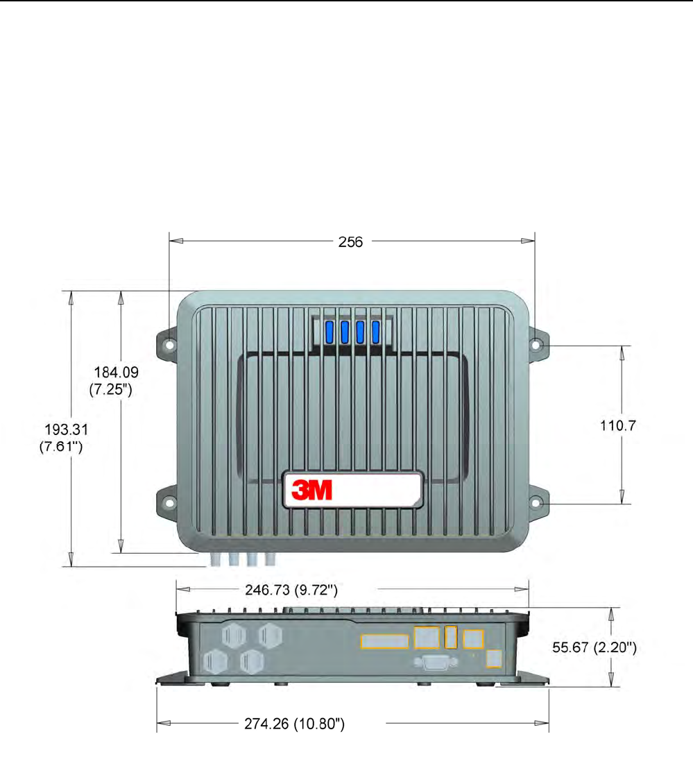
3.1.1. Mounting the Reader
The 1000 is equipped with four mounting flanges with thru-holes that
accept four #8 (M4) mounting screws. Pre-drill any mounting surface
according to the following dimensions. Any mounting surface must be able
to support up to 5 pounds (2.3 kg).
Figure 3 3M Compact RFID Reader 1000 Mechanical Dimensions (dimensions in mm)
1 2 3 4 5 6 7 8 9 Reader Equipment Installation
10 3M Compact RFID Reader 1000 User’s Guide
Concrete Wall Mounting
To mount the reader to a hollow concrete block wall, 3M recommends
metal sleeve type concrete anchors that accept #8 screws and flat washers.
Wood or Metal Wall Mounting
To mount the reader to a wood or sheet metal wall, 3M recommends either
#8 x 1 inch wood screws or #8 x 1 inch sheet metal screws and washers.
Drywall Mounting
To mount the reader to drywall or sheetrock, 3M recommends either #8
toggle bolts or #8 drywall anchors.
3.1.2. Mounting the Antennas
The 1000 supports from one to four antennas in a variety of configurations.
The optional 3M provided antennas must be installed on a solid surface or
frame to prevent damage or later misalignment. It is highly recommended
that the antenna mounting be adjustable in order to obtain the best
performance from the system.
1 2 3 4 5 6 7 8 9 Reader Equipment Installation
3M Compact RFID Reader 1000 User’s Guide 11
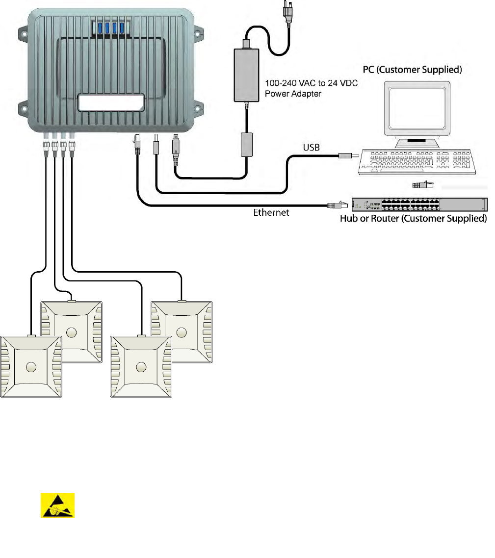
3.2. Electrical Installation
Figure 4 3M Compact RFID Reader 1000 Electrical Connections
NOTICE: The 3M Compact RFID Reader 1000 is designed to meet the regulatory requirements in
those jurisdictions in which it is offered. Changes or modifications not expressly approved
by 3M for compliance could void the user's authority to operate the equipment.
ATTENTION 3M Compact RFID Reader 1000 antenna ports may be susceptible to
damage from static discharge or other high voltage. Use proper
Electrostatic Discharge (ESD) precautions to avoid static discharge when
handling or making connections to the 1000 reader antenna or
communication ports. Equipment failure can result if the antenna or
communication ports are subjected to ESD.

1 2 3 4 5 6 7 8 9 Reader Equipment Installation
12 3M Compact RFID Reader 1000 User’s Guide
3.2.1. Connecting the Serial Port
The 1000 is equipped with one DB9 type RS-232 serial port for
communication up to 115200 Baud. If you are using the serial port for
reader communication, connect a serial cable from the COM port on your PC
to the serial port on the reader. See Figure 2 for location of the connector.
The maximum serial cable length is 12 feet at 115200 Baud.
3.2.2. Connecting the USB Ports
The 1000 is equipped with two USB 2.0 ports. The USB Type B port provides
connectivity to the 1000 console. This connection is used to send
commands and receive responses and is typically connected to your server.
The USB Type A port is used for external devices such as printers, external
hard drives, or other peripherals.
For standard communications, connect a USB Type B cable to the reader
and then to your PC or server. The maximum cable length is 5 meters to the
nearest hub, router, or computer.
3.2.3. Connecting and Configuring the Ethernet Port
The maximum Ethernet cable length is 30 meters. If you are communicating
with your reader across a Local Area Network (LAN), connect an Ethernet
cable from your hub or router to the RJ-45 connection. See Figure 2 for
location of the connector. If you are connecting the reader directly to a PC,
you must use a crossover cable. See Note to the left.
By default, the reader is configured to use a DHCP server to obtain its IP
address and related information. In the event a DHCP server is unavailable,
the reader will boot with an IP address in the 169.254.x.x subnet.
In the absence of other readers on the same network, and if no other
network traffic is observed which references 169.254.1.1, the reader will
select that address; otherwise, it will select a random address on the
169.254.x.x subnet.
IP address settings can be changed using RST. Refer to the View or Change
the Reader’s Network Settings section in Chapter 5.
Ethernet Cables
In most cases, you
will connect the 3M
Compact RFID
Reader 1000 to a
network hub or
router. However, if
you are connecting
directly to a PC or
other computer,
you will need a
Crossover Cable
that swaps the Tx
and Rx signals.

1 2 3 4 5 6 7 8 9 Reader Equipment Installation
3M Compact RFID Reader 1000 User’s Guide 13
3.2.4. Connecting the Antennas
The maximum antenna cable length is 10 meters. Connect the antenna to
antenna port 1. If you are using additional antennas connect them to Ports
2–4.
Antennas can be connected as monostatic, bistatic, or a combination of the
two. If using bistatic configurations, these antenna pairs are defined on
ports 1/2 and 3/4.
NOTICE: The 3M Compact RFID Reader 1000 is equipped with one (1) auxiliary RF port which is
inactive when shipped from the factory. If activated, this RF port must be properly terminated
with a 50 ohm load or a functional UHF antenna before power up. Always power down the
reader before removing an antenna or load from an RF port.
The maximum antenna cable length is 10 meters.
ATTENTION The 3M Compact RFID Reader 1000 antenna port may be susceptible to
damage from static discharge or other high voltage. Use proper
Electrostatic Discharge (ESD) precautions to avoid static discharge when
handling or making connections to the 1000 reader antenna or
communication ports. Equipment failure can result if the antenna or
communication ports are subjected to ESD.
3.2.5. Connecting Digital Inputs/Outputs
The 1000 is equipped with a general purpose digital input/output (I/O) port
that provides four optically isolated 5-24 VDC input signals and four open-
collector output signals. The digital inputs can be used as general purpose
inputs or to trigger the reader for tag reading. These inputs can be
configured to provide an external read trigger from proximity sensors, photo
switches, or other devices.
The digital outputs can be used as general purpose outputs, to indicate tag
reading activity, or to indicate the reader is transmitting (RF On). The
outputs can also be configured to trigger conveyor gates or other access
control and sorting devices. For detailed information on configuring the
digital inputs and outputs refer to Chapter 7.
1 2 3 4 5 6 7 8 9 Reader Equipment Installation
14 3M Compact RFID Reader 1000 User’s Guide
3.2.6. Connecting the Power
Connect the 24 VDC power adapter to the reader and connect the power
supply to your 100–240 VAC, 50-60 Hz power source. Allow 30 seconds for
the reader to initialize.
NOTICE: If DC power is disconnected from the reader, wait a minimum of 30 seconds before
reapplying power.
1 2 3 4 5 6 7 8 9
RST Software Installation
3M Compact RFID Reader 1000 User’s Guide 15
4 Reader Startup Tool (RST) Software Installation
4.1. Installing RST Software
The 1000 is delivered with a Microsoft Windows application called Reader
Startup Tool (RST). You can use this application to initially configure your
reader as well as read and display tag data.
Install RST
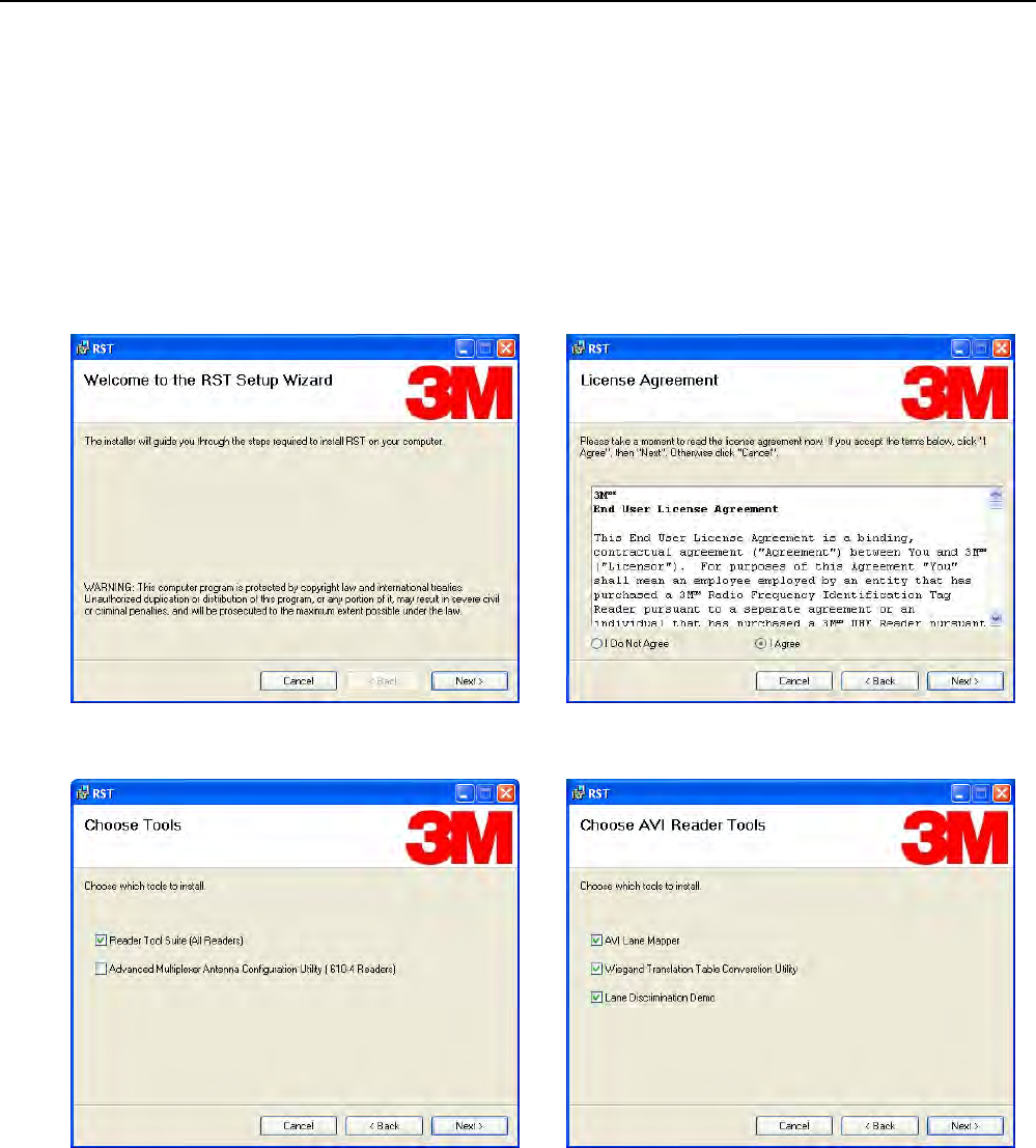
1 To install RST, load your product CD and double-click the
RSTInstaller.msi file:
2 Press Next> 3 Read the License Agreement. Select
I Agree and press Next>
4 Select Reader Tool Suite. Press Next>. 5 Choose the AVI Reader Tools you need.
Press Next>.
1 2 3 4 5 6 7 8 9 RST Software Installation
16 3M Compact RFID Reader 1000 User’s Guide
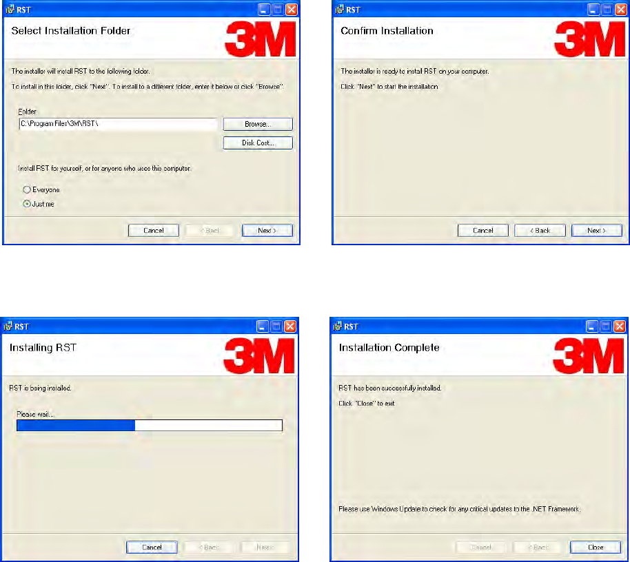
5 Verify the path and folder where RST will be
installed. Press Next>.
6 Press
Next>.
7 Monitor the progress of the installation. 8 After the installation completes, press
Close.
1 2 3 4 5 6 7 8 9
RST Software Installation
3M Compact RFID Reader 1000 User’s Guide 17
4.2. Windows 7 Setup
If you have a Windows 7 operating system, your firewall may block UDP
traffic and consequently RST may not discover your readers. Perform the
following to configure your system:
For Microsoft Firewall
1 Log into your computer as Administrator.
2 Navigate to the Control Panel and select
Control Panel → System and Security.
3 Select Allow a program through Windows firewall.
4 Scroll down the list and locate Startup Tool, check it, and press OK.
5 If Startup Tool is not in the list, press Allow another program.
6 Locate Startup Tool, check it, and press OK.
7 Restart RST and it should discover readers.
For Third-Party Firewalls
1 Log into your computer as Administrator.
2 Set your firewall to allow RST to receive UDP traffic on port 50000 and
50001.
1 2 3 4 5 6 7 8 9 RST Software Installation
18 3M Compact RFID Reader 1000 User’s Guide
4.3. Reader Startup
To begin using your reader, open the RST application.
Open RST
1 From your Windows desktop, select:
Start→Programs→3M→Reader Startup Tool (RST)
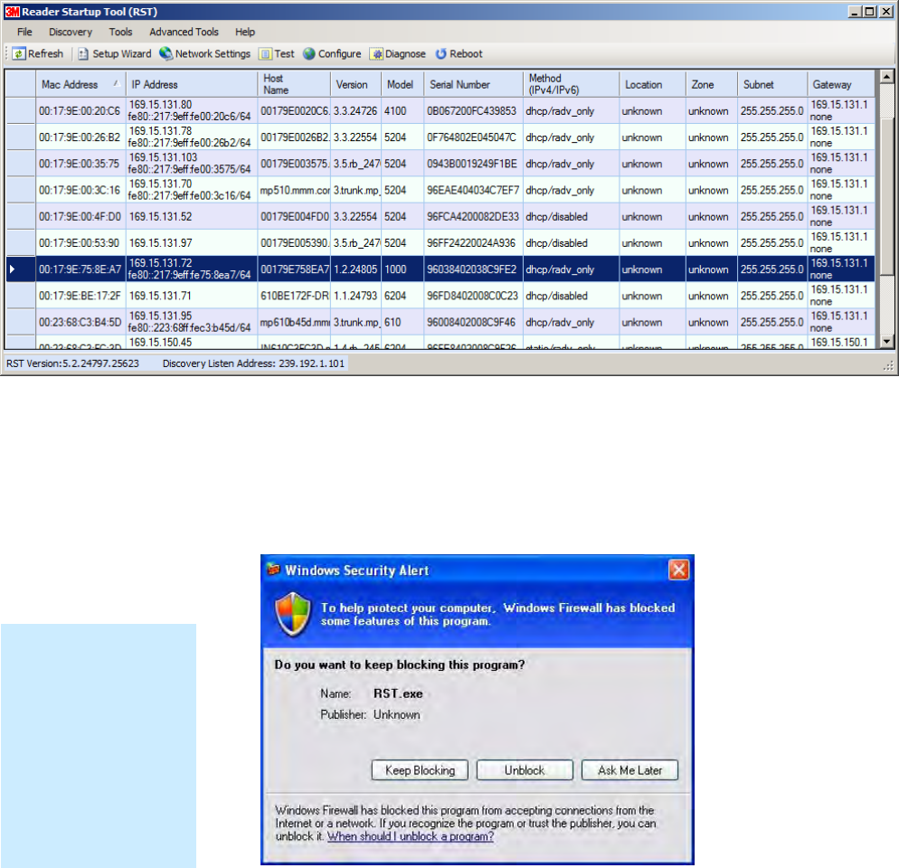
2 If this is the first time starting the RST application, you may receive a
Windows Security Alert. This warning indicates that the firewall is
blocking the RST application.
3 If the warning window is hidden under the RST windows, collapse the
RST window.
4 Press Unblock.
NOTE:
Earlier versions of
Microsoft Windows™
may not provide the
Security Alert popup.
IF RST does not
discover your reader,
check your Windows
Firewall/Security
settings.
1 2 3 4 5 6 7 8 9
RST Software Installation
3M Compact RFID Reader 1000 User’s Guide 19
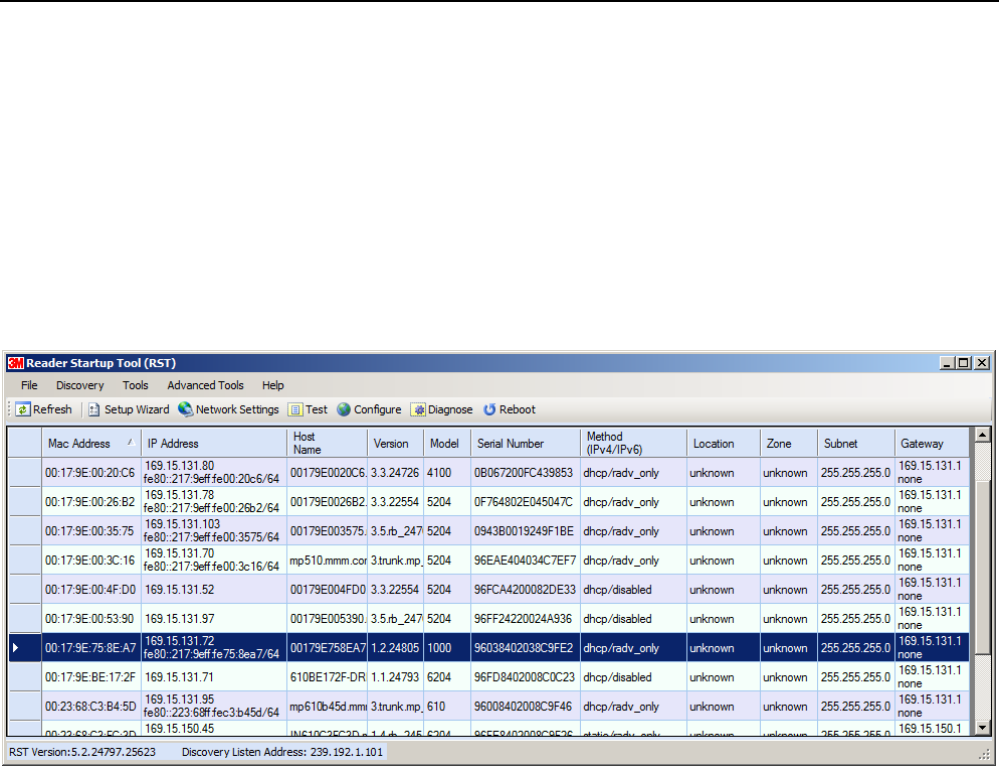
5 Press Refresh on the RST
6 The RST main page will display any readers currently connected to the
network.
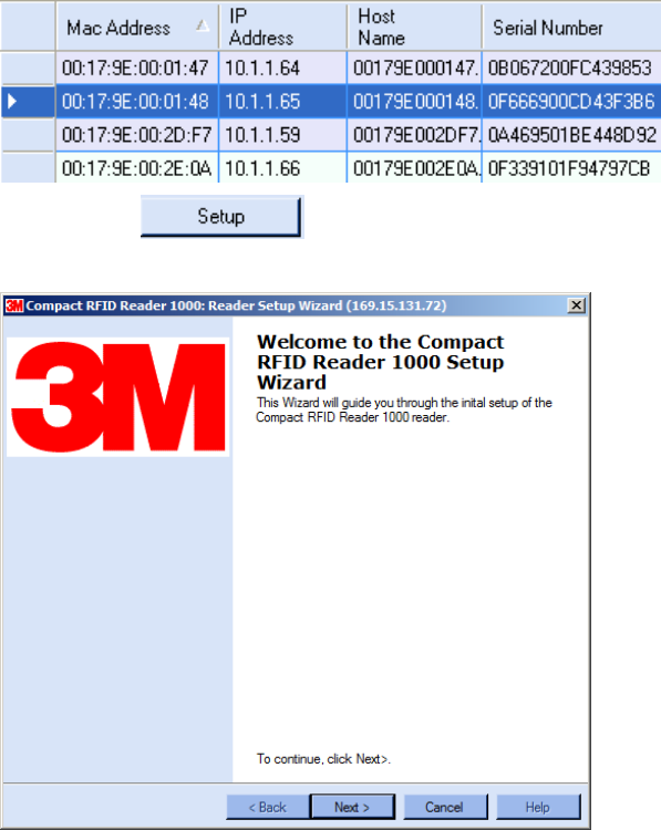
4.4. Initial Reader Setup
To configure a specific reader, perform the following:
Reader Setup
1 Select the reader on the main RST page by clicking the button to the left
of the reader Mac address.
2 Press the button on the RST window.
3 The 1000 Setup Wizard (RSW) is displayed.
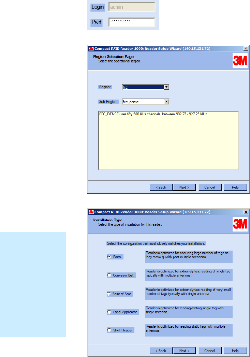
4 Press Next> and enter the Login (admin) and Password. If this is the
first time configuring your reader, enter: readeradmin.
1 2 3 4 5 6 7 8 9 RST Software Installation
20 3M Compact RFID Reader 1000 User’s Guide
5 After entering your Login and Password, press Next>
6 Select the Region and Sub Region and press Next>.
7 Select a configuration that most closely resembles your installation and
press Next>.
Custom Setup
If your installation
type differs from one
of the choices shown
in the Setup Wizard,
you can always
customize your setup
later using the
embedded web
interface capability.
See the Advanced
Setup chapter in this
guide for more
information.
1 2 3 4 5 6 7 8 9
RST Software Installation
3M Compact RFID Reader 1000 User’s Guide 21
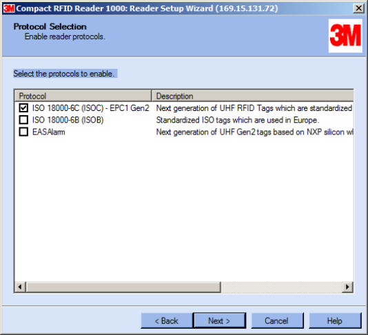
8 Select the protocol of the tags you will be reading and press Next>.
1 2 3 4 5 6 7 8 9 RST Software Installation
22 3M Compact RFID Reader 1000 User’s Guide
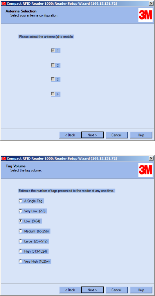
9 Select the antennas you will be installing and press Next>.
10 Estimate the number of tags that will be presented to the reader at any
one time and press Next>.
1 2 3 4 5 6 7 8 9
RST Software Installation
3M Compact RFID Reader 1000 User’s Guide 23
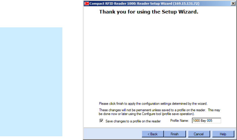
11 It is highly recommended that you save the reader setup as a profile.
Select Save changes to a profile…, enter a Profile Name, and press
Finish to complete the initial reader setup.
Saving Reader Setup
Reader setup
information should be
saved as a profile. In
the event that you
need to reboot or
power down a reader,
the reader setup can
be quickly reloaded
by loading the profile.
If you don’t save the
reader setup, you can
loose the information
if the reader is
rebooted.
1 2 3 4 5 6 7 8 9 Reader Operation
24 3M Compact RFID Reader 1000 User’s Guide
5 Reader Operation
5.1. Basic Operation with RST
The 3M Compact RFID Reader 1000 can be operated either from the RST
application or by logging directly into the reader’s embedded Reader
Configuration Tool (RCT). To operate the reader from RST, perform the
following:
Open RST
1 From your Windows desktop, select:
Start→Programs→3M→Reader Startup Tool (RST)
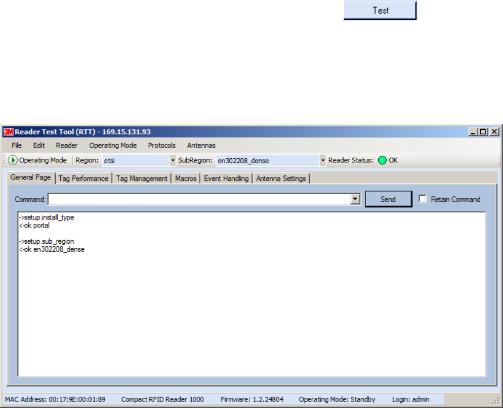
2 Select a specific reader and press Test.
3 The Reader Test Tool (RTT) is displayed.
1 2 3 4 5 6 7 8 9
Reader Operation
3M Compact RFID Reader 1000 User’s Guide 25
4 Login to the reader. From the pull-down menu select Reader→Login….
5 For administrator login, select admin. The initial password (Pwd) is
readeradmin. See Advanced Setup section to change the password.
6 Verify the Operating Mode is set to Active. From the pull-down menu
select Operating Mode→Active.
7 Select the Tag Performance tab and press Start.
8 Place tags in front of antenna and verify tags are read and displayed.
1 2 3 4 5 6 7 8 9 Reader Operation
26 3M Compact RFID Reader 1000 User’s Guide
5.2. Deployed Reader Operation with RCT
Once your readers are deployed, you can access them directly using the
embedded Reader Configuration Tool (RCT). To access a particular reader,
perform the following:
1 Enter the reader’s IP address into your web browser or press the
button on the main RST page.
2 The reader’s RCT interface is displayed.
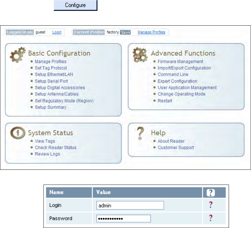
3 Log into the reader. Press Login for the login screen.
4 The default login is guest. If you need administrator privileges, login as
admin and enter readeradmin as the password.
5 Press Submit.
6 Select Basic Configuration →Setup Antenna/Cables to configure the
antennas, gain, and power settings.
1 2 3 4 5 6 7 8 9
Reader Operation
3M Compact RFID Reader 1000 User’s Guide 27
7 Select Advanced Functions →Change Operating Mode to verify the
reader is in the proper mode.
8 Select Basic Configuration →Set Tag Protocol to verify the reader is
configured for the proper tag protocol.
9 Press System Status →View Tags to view tag data.
10 If you need to configure your reader, refer to Chapter 7 – Reader
Configuration Tool for information on using RCT to adjust configuration
variables and parameters.
1 2 3 4 5 6 7 8 9 Reader Startup Tool
28 3M Compact RFID Reader 1000 User’s Guide
6 Reader Startup Tool (RST)
The Reader Startup Tool (RST) provides an easy-to-use interface for the 3M
Compact RFID Reader 1000 configuration and operation functions. This
application resides on your Windows based computer and allows you to
perform the following:
View all readers on the network
Launch the Reader Setup Wizard to configure a reader
View and change a reader’s network settings
Add a new reader to the network
Launch Reader Test Tool to perform basic reader/tag operations
Launch Reader Diagnostic Tool to view statistics, alarms, and reports
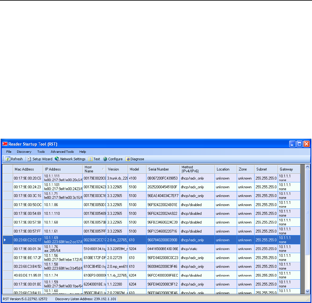
6.1. View Readers on the Network
When RST starts up, all readers currently connected to the network and
powered up are displayed.
1 2 3 4 5 6 7 8 9
Reader Startup Tool
3M Compact RFID Reader 1000 User’s Guide 29
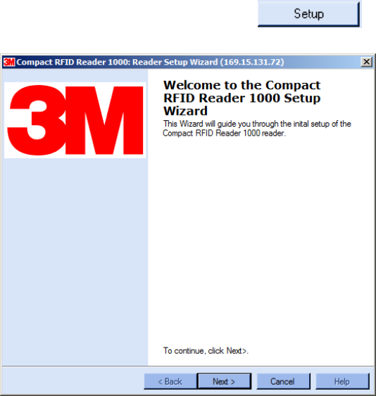
6.2. Configure Reader with the Setup Wizard
The Reader Setup Wizard is used to initially configure your reader for
operation. With this application, you can select the following:
Installation type
Regulatory region and sub-region
Protocol
Number of antennas
Estimated tag volume
To initially configure your reader perform the following:
1 From the RST main page, press the button. The Setup
Wizard is launched as shown.
2 Refer to Chapter 2 – Reader Configuration for detailed instructions on
using the Reader Setup Wizard.
1 2 3 4 5 6 7 8 9 Reader Startup Tool
30 3M Compact RFID Reader 1000 User’s Guide
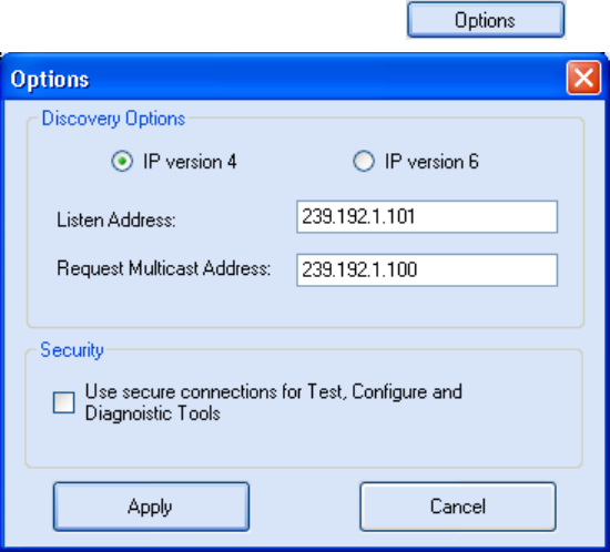
6.3. Customize Discovery Options
You can customize the reader discovery options including the Listen
Address and Request Multicast Address.
Listen Address – Address that RST uses to listen for UDP discovery
packets from the reader. This is customizable on the reader.
Request Multicast Address –Address used by RST to send out the UDP
update request packets. This is customizable on the reader.
In addition, you can select if you want a secure connection for the Test,
Configure, and Diagnostic Tools. This connection uses the HTTPS protocol
and any data transferred between devices is encrypted.
1 From the RST main page, press the button.
2 Select either IP version 4 or IP version 6.
3 Enter the Listen Address and Request Multicast Address as required.
4 Select whether you require a secure connection for the Test, Configure,
and Diagnostic Tools.
5 Press Apply.
1 2 3 4 5 6 7 8 9
Reader Startup Tool
3M Compact RFID Reader 1000 User’s Guide 31
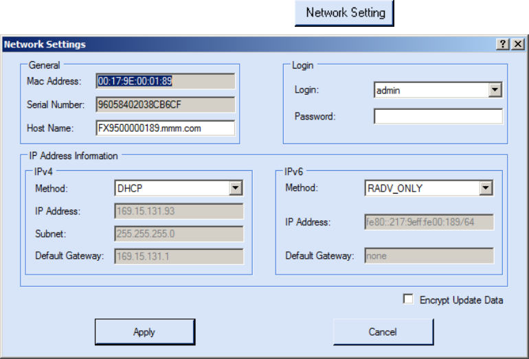
6.4. View or Change the Reader’s Network Settings
1 From the RST main page, press the button.
2 Verify the IP Address, Subnet, and Default Gateway are correct.
3 If Enable DHCP is selected these fields will be locked.
4 If required, change the values.
5 If your reader is running Version 2.0 or later firmware, enter your login
and password.
6 Press Apply.
1 2 3 4 5 6 7 8 9 Reader Startup Tool
32 3M Compact RFID Reader 1000 User’s Guide
6.5. Reader Test Tool (RTT)
The Reader Test Tool (RTT) is primarily designed for new users to test
reader operation and perform a few basic reader functions. With RTT, you
can perform the following:
Read tags
Issue commands to the reader and view the responses
Run macros
Observe reader events
To access the Reader Test Tool, press the button on the
main RST page.
6.5.1. General Page
The General Page allows you to issue commands to the reader and view
any responses. From the pull-down menus, you can also login to the reader,
change the operating mode, select another protocol, and select which
antennas are active.
1 2 3 4 5 6 7 8 9
Reader Startup Tool
3M Compact RFID Reader 1000 User’s Guide 33
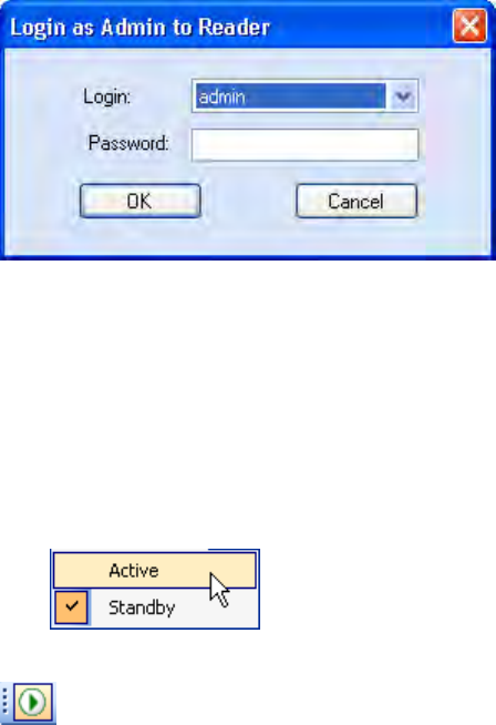
Login to Reader
To login to the reader, perform the following:
1 From the pull-down menu, select Reader→Login….
2 Select the type of Login from the pull down. The default login is guest. If
you need administrator privileges, login as admin.
3 Enter your Password. Enter readeradmin as the password if you logged
in as admin.
4 Press OK.
Select Operating Mode
From the pull-down menu, select Operating Mode→<Active | Standby>
or, press the Operating Mode select button on the left side of the tool bar.
Active – Reader is continuously attempting to singulate tags and
automatically reports any singulated tag via an asynchronous event
notification on the event channel.
Standby – Reader is not transmitting any RF energy, unless processing
a tag related command. The transmitter is enabled at the beginning of
the command processing, protocol operations required for the
command are performed, and then the RF transmitter is turned off.
1 2 3 4 5 6 7 8 9 Reader Startup Tool
34 3M Compact RFID Reader 1000 User’s Guide
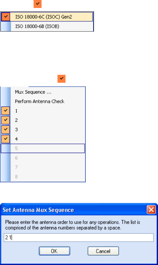
Select Protocol
You can activate one or more protocols on the 1000 using RST. From the
pull-down menu, select Protocols→<protocol>. Active protocols are
indicated by .
Antenna Selection
You can select the ports that have antennas connected and which antennas
are active. Perform the following:
1 From the pull-down menu, select Antennas→<n>. Active antennas
are indicated by .
2 You can also select the order in which antennas are activated. From the
pull-down menu, select Antennas→Mux sequence....
3 Enter the antenna numbers in the order to be activated.
4 Press OK.
1 2 3 4 5 6 7 8 9
Reader Startup Tool
3M Compact RFID Reader 1000 User’s Guide 35
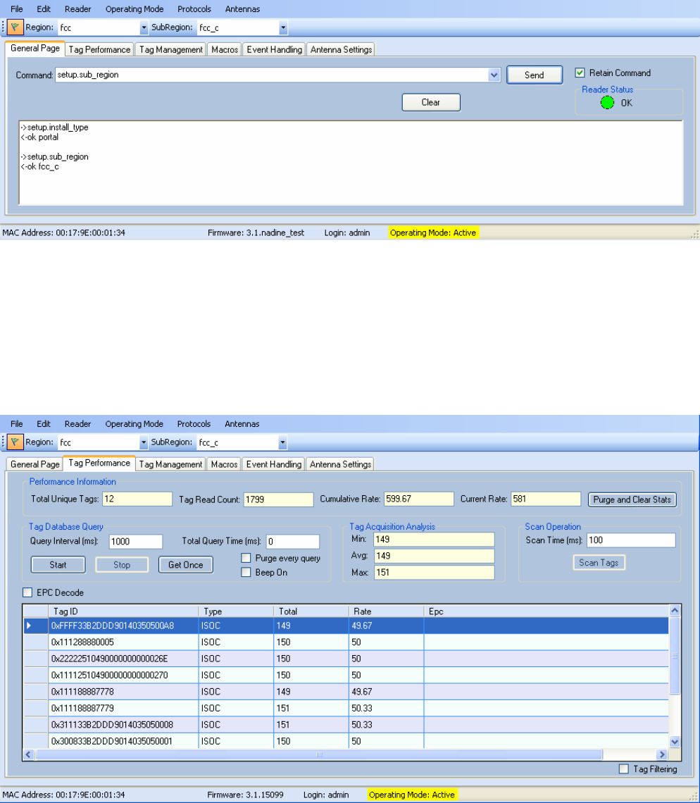
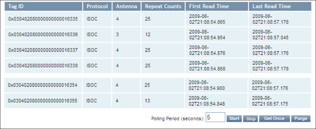
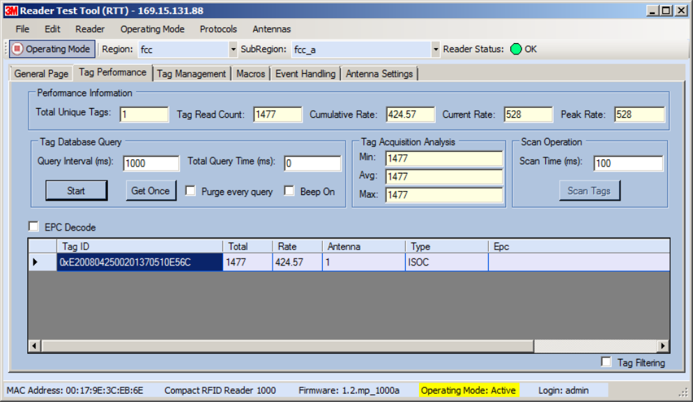
6.5.2. Tag Performance Page
The Tag Performance page is used to test the reader performance.
Although it is best suited for reading large populations (hundreds) of tags,
as in a multi-antenna portal, it also is useful for range (distance) testing of
one tag with one antenna.
To initiate a timed test, enter the length of test (in ms) into the Total Query
Time field. For example, to verify to number of tags read in a 30-second
interval, select Active Operating Mode, enter 30000, and press the Start
button. The test will complete after 30 seconds and the output statistics are
updated for the query time.
Output statistics are read-only and include: Total Unique Tags, Tag Read
Count, Cumulative Rate, and Current Rate.
Detailed descriptions of the various Tag Performance fields and functions
are provided in the following sections.
Tag read controls are provided by the Tag Database Query and Scan
Operation blocks. Use the Query controls when the reader is in Active
mode. Use the Scan Operation controls when in Standby mode.
Tag and reader performance data is provided in the Performance
Information and Tag Acquisition Analysis blocks.
1 2 3 4 5 6 7 8 9 Reader Startup Tool
36 3M Compact RFID Reader 1000 User’s Guide
Performance Information
Total Unique Tags – Number of unique tags in the tag database.
Tag Read Count – Total number of tags read (including repeat reads).
Cumulative Rate – Cumulative read rate in tags/second since the Start
button was pressed.
Current Rate – Current read rate in tags/second.
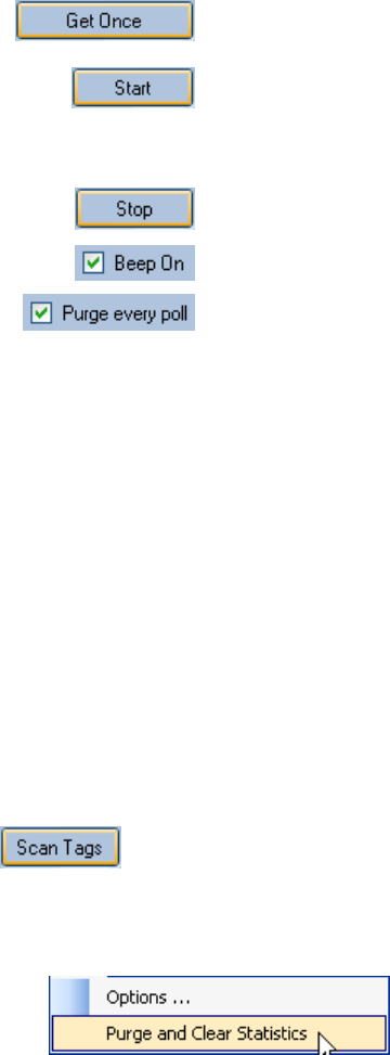
Tag Database Query Controls
Click to retrieve the current information from reader’s
tag database.
Click to query the tag database every Query Interval
(ms) for a total time of Total Query Time (ms). Do not
set the interval less than 500. If Total Query Time is
set to 0, query continues indefinitely.
Click to stop automatic query.
Indicates current read rate with audible tone.
Check to purge the reader’s tag database after each
query. Refer to the 3M Compact RFID Reader 1000
Protocol Reference Guide for more information on the
tag database.
Tag Acquisition Analysis
The Tag Acquisition Analysis fields provide the minimum, maximum, and
average number of times each tag was read. For example, assume five tags
(A, B, C, D, and E) are read 107, 59, 223, 187, and 94 times respectively.
The displayed values are as follows:
Min = 59
Avg = 134
Max = 223
Scan Operation
Scan time (ms) – Enter the duration of reader operation in milliseconds.
After this time expires, the tag information is displayed.
Press this button to activate the reader.
Purge and Clear Reader Statistics
Select the reader and then select Edit→Purge and Clear Statistics.
1 2 3 4 5 6 7 8 9
Reader Startup Tool
3M Compact RFID Reader 1000 User’s Guide 37
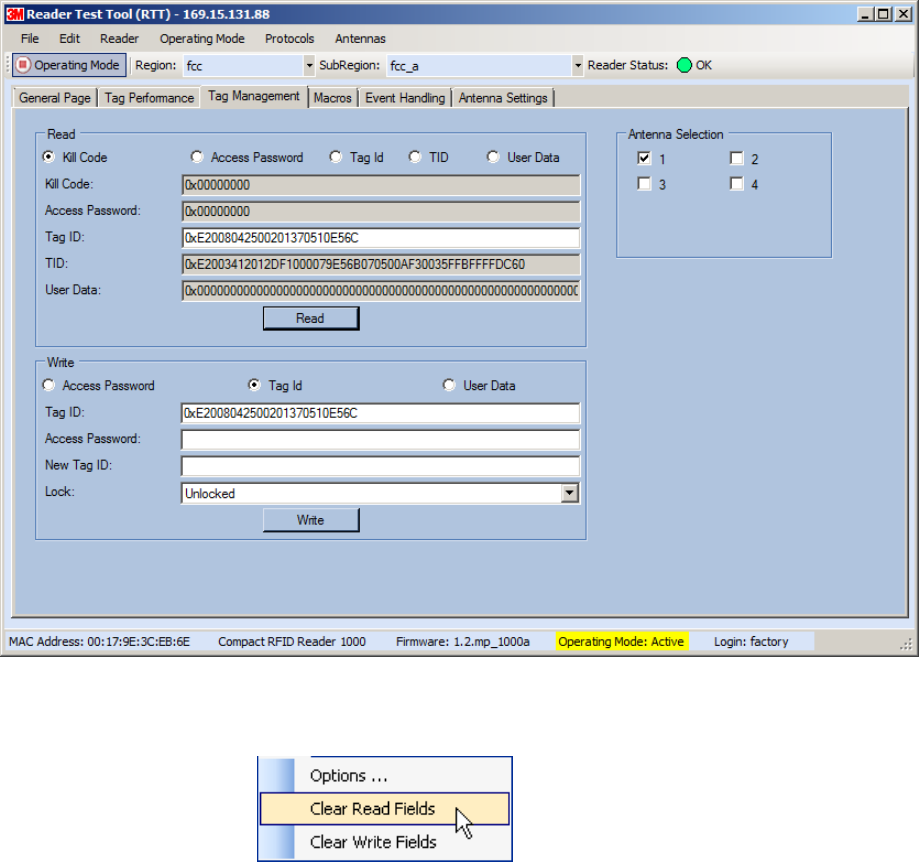
6.5.3. Tag Management Page
The Tag Management page is used for reading individual fields on a single
tag as well as writing the access password and locking a tag. The Read
button will cause the reader to singulate and read a tag in the selected
antennas’ RF field. Specific fields you can read include:
Kill Code
Access Code
Tag ID
TID
User Data
Clear Read and Write Fields
To clear the Read or Write fields, select Edit→Clear….
1 2 3 4 5 6 7 8 9 Reader Startup Tool
38 3M Compact RFID Reader 1000 User’s Guide
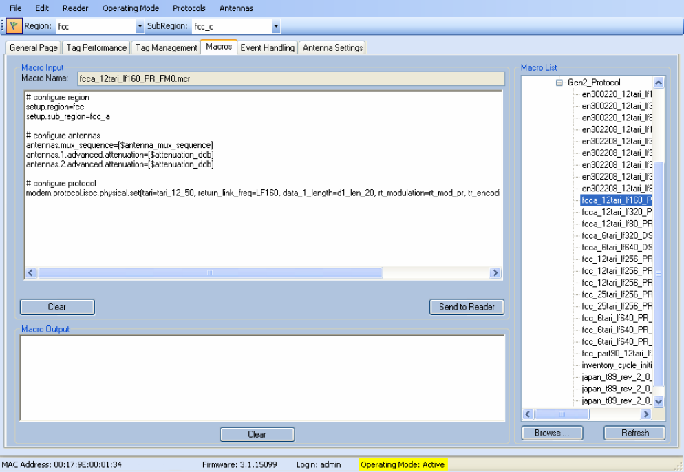
6.5.4. Macros Page
The Macros page allows the reader to manage macro files. The macros are
provided by 3M or can be written by the end user. Some of the macros
provided are dependent on the operating region of the reader.
A macro (script or command file) is a text file that contains one or more
reader commands. These commands are used to configure the reader to a
known configuration. The Macros can contain variables. These variables are
resolved by a dialog box (Macro Variables) that appears when the Send to
Reader button is selected. The syntax of a variable is:
[$variable_name]
During execution, the variable is replaced with user entries into the Macro
Variables dialog box. Macros can be edited with any text editor including
Windows Notepad.
1 2 3 4 5 6 7 8 9
Reader Startup Tool
3M Compact RFID Reader 1000 User’s Guide 39
Macro Input sub-window
The Macro Input window shows the current script that will be sent to the
reader when the Send to Reader button is selected. The text in the Macro
Input window can be edited prior to being sent to the reader.
Macro Output sub-window
The Macro Output window is updated after the Send to Reader button is
selected. Look at this window to verify that each command line in a script
executed correctly. Look for the −−>> ok response from the reader for each
command line.
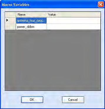
Macro Variables Dialog box
When a macro is sent to the
reader, the values for variables
must be resolved via this Windows
Dialog box. You can [tab] to each
value field and enter the desired
value.
For example, one macro can be
used for two different applications
by using variables for antenna
selection and transmit power.
Macro Example
To configure the reader for ETSI, EN302208 Dense, four-antenna portal
operation, send the following macro (en302208_12tari_lf320_PR_M4.mcr):
# configure region
setup.region=etsi
setup.sub_region=EN302208_DENSE
antennas.mux_sequence=[$antenna_mux_sequence]
antennas.1.conducted_power=[$power_ddbm]
antennas.2.conducted_power=[$power_ddbm]
antennas.3.conducted_power=[$power_ddbm]
antennas.4.conducted_power=[$power_ddbm]
# configure protocol
modem.protocol.isoc.physical.set(tari=tari_12_50, return_link_freq=LF320,
data_1_length=d1_len_20, rt_modulation=rt_mod_pr,
tr_encoding=tr_enc_miller_4,interrogator_mode=dense)
1 2 3 4 5 6 7 8 9 Reader Startup Tool
40 3M Compact RFID Reader 1000 User’s Guide
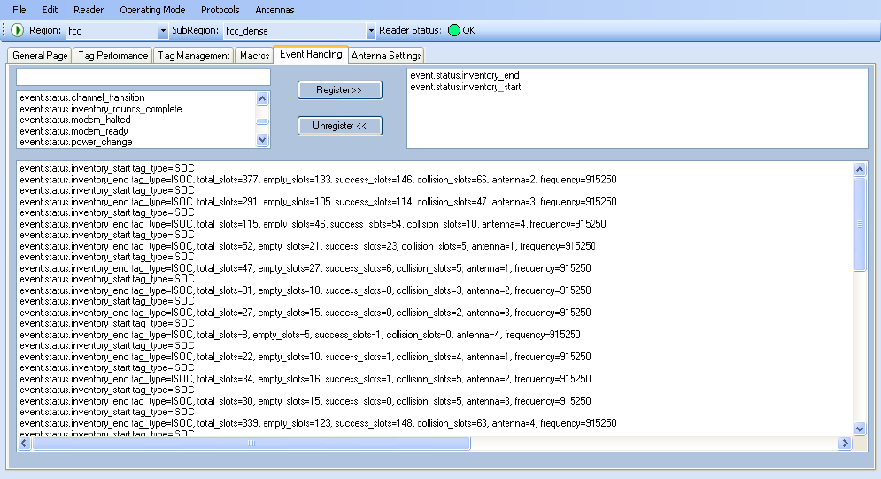
6.5.5. Event Handling Page
The Event Handling page allows you to register for Reader Events. After
registration, events are displayed with the newest on the bottom and the
most recent event will scroll to the bottom of the window. Individual events
or a group of events can be registered. For detailed information on
individual events, refer to Chapter 18 – Events Namespace of the 3M
Compact RFID Reader 1000 Protocol Reference Guide.
Registering for an individual event
To register for an individual event, either type the event name or select an
event from a pull-down list.
Registering for a group of events
Registering for event.error events, will cause the reader to autonomously
send all events in the event.error namespace to the RTT program and be
displayed in the window of this page. Enter event.error in the Events: field
and press the Register button. The Clear button can be selected at any
time to clear the window.
1 2 3 4 5 6 7 8 9
Reader Startup Tool
3M Compact RFID Reader 1000 User’s Guide 41
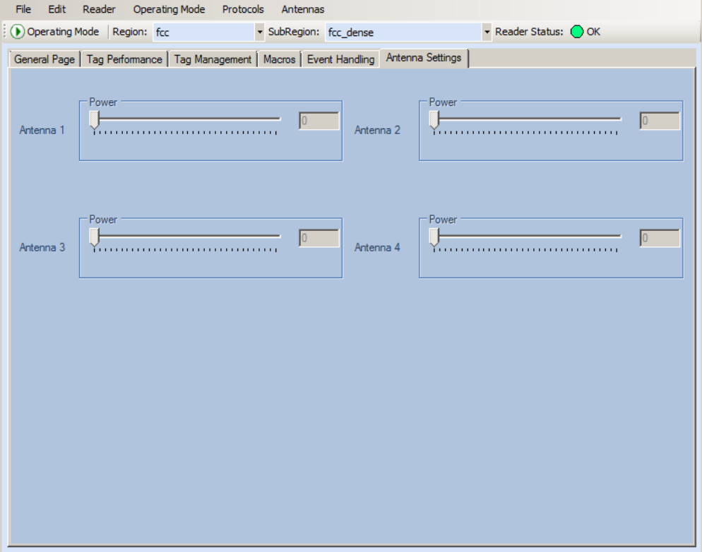
6.5.6. Antenna Settings Page
The Antenna Settings page allows you to adjust the power settings for each
antenna. Only the controls for those antennas that are connected are
activated.
1 2 3 4 5 6 7 8 9 Reader Startup Tool
42 3M Compact RFID Reader 1000 User’s Guide
6.6. Reader Diagnostics Tool (RDT)
The Reader Diagnostic Tool (RDT) is to be used by 3M trained technicians to
troubleshoot and diagnose various reader issues. Administrator login is
required.
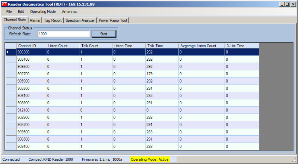
6.6.1. Channel Statistics
The Channel Stats page shows details of channel changes. This page is
typically used to observe regional behavior.
1 2 3 4 5 6 7 8 9
Reader Startup Tool
3M Compact RFID Reader 1000 User’s Guide 43
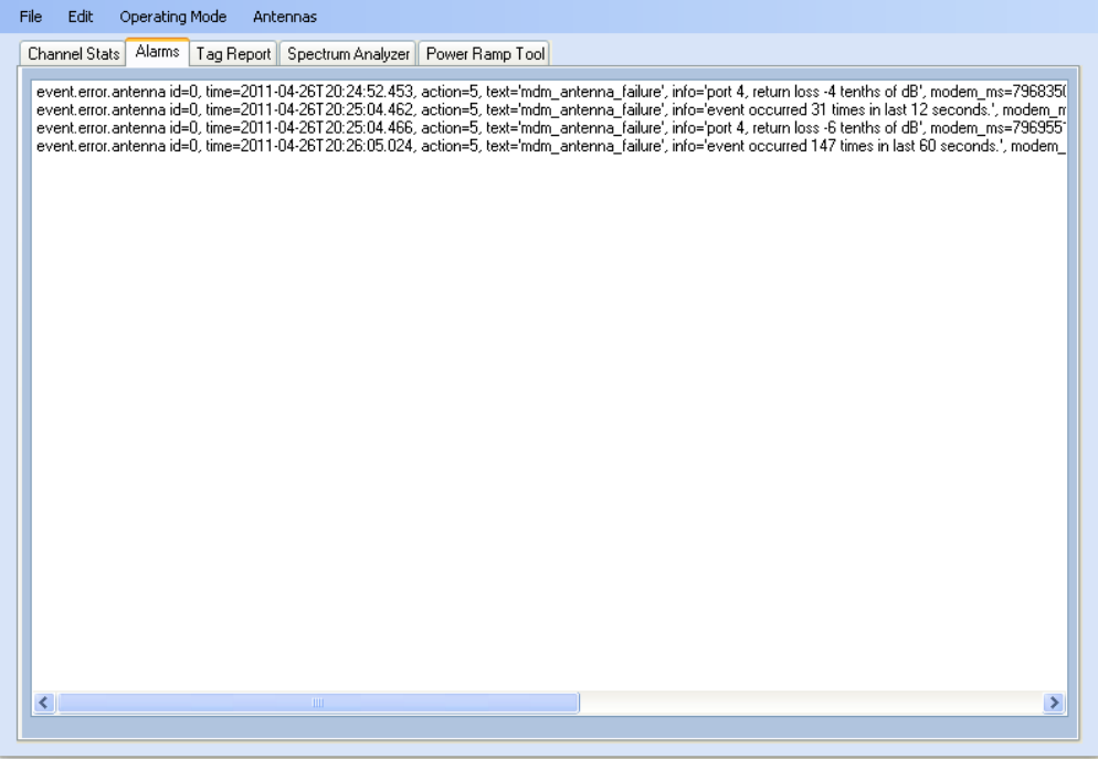
6.6.2. Alarms
The Alarms page is used to capture autonomous alarms generated by the
reader during normal operation. The alarms are defined as autonomous
reader events for the following namespaces:
event.error
event.warning
1 2 3 4 5 6 7 8 9 Reader Startup Tool
44 3M Compact RFID Reader 1000 User’s Guide
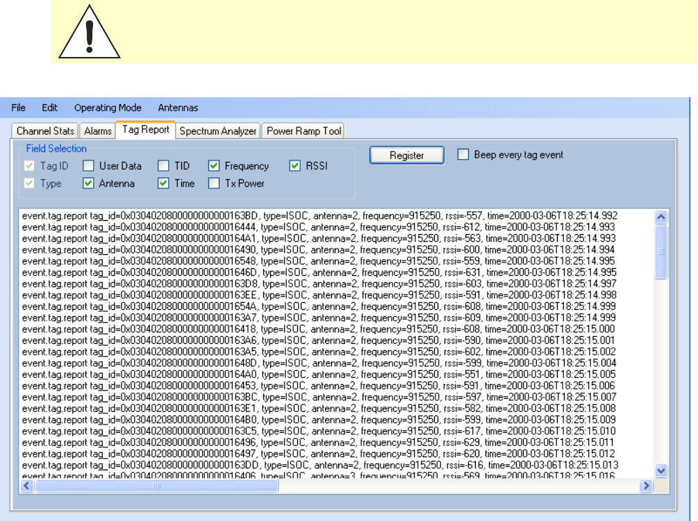
6.6.3. Tag Report
The Tag Report page is used to view specific information for each tag
singulation. This feature provides detailed attributes of tag singulations
such as tag power (RSSI) and on which antenna that tag singulated.
Caution: Use of this tool can adversely affect tag reader performance, particularly if many
tag fields are enabled. Use the RTT->Tag Performance page for normal tag
performance testing.
1 2 3 4 5 6 7 8 9
Reader Startup Tool
3M Compact RFID Reader 1000 User’s Guide 45
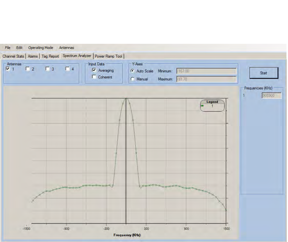
6.6.4. Spectrum Analyzer
The Spectrum Analyzer allows you to examine the spectral composition of
the radio waves in your surrounding environment. This feature provides a
graphical representation of the current spectral RF noise in units of dBm
with a range of 0 to -120 dBm. This feature is intended for expert users to
verify RF environmental conditions during an installation.
NOTICE: Using this feature during normal reader operation can significantly degrade tag reading
performance.
1 2 3 4 5 6 7 8 9 Reader Startup Tool
46 3M Compact RFID Reader 1000 User’s Guide
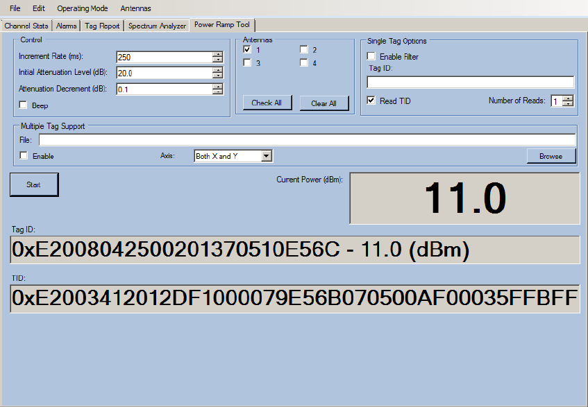
6.6.5. Power Ramp Tool
The Power Ramp Tool determines the minimum power to activate a tag and
can help determine tag quality. This activation power level can help
determine the read range at various attenuation levels and, for AVI
applications, can help determine the "read-zone" or an antenna pattern.
The tool starts by configuring the reader to start transmitting at a low
attenuation level (usually 0.1 dBm) and increments the level until it
observes a response from the tag. The transmitter is turned off and the
minimum value to activate the tag for a given antenna and distance is
reported.
The Power Ramp controls include:
Increment Rate (ms) – Time tool stays at a particular power level
before incrementing to the next power level.
Initial Attenuation Level (dBm) – Starting attenuation level.
Attenuation Decrement (dBm) – Step-size for attenuation
decrement.
Antennas section allows you to select which antenna(s) to test with.
Filter section allows you to apply a filter to only look for a particular tag.
1 2 3 4 5 6 7 8 9
Reader Configuration Tool
3M Compact RFID Reader 1000 User’s Guide 47
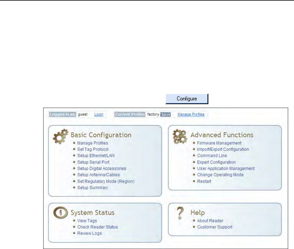
7 Embedded Reader Configuration Tool (RCT)
The Embedded Reader Configuration Tool (RCT) allows you to access your
reader across the internet by entering the reader’s IP address into your web
browser. With the RCT, you can fully configure your reader for operation in a
variety of applications and environments. With this application, you can
perform the following:
Basic Configurations
Advanced Configurations
Check System Status
Access the online Help
To access the RCT, press the button on the main RST page.

1 2 3 4 5 6 7 8 9 Reader Configuration Tool
48 3M Compact RFID Reader 1000 User’s Guide
7.1. Basic Configuration
With the Basic Configuration functions you can perform the following:
Manage reader profiles
Set tag protocols
Setup the Ethernet/LAN configuration
Setup the serial port
Setup digital accessories
Setup antennas
Set regulatory modes
7.1.1. Configuration Page Header
Each page displayed by the RCT has the following header.
This header provides pull-down menus for each of the configuration
function categories. Additional functions include the user login and the
currently loaded reader profile.
Login
The reader’s default user level is guest. However, a user can login as admin.
If not logged in as admin, the default level is always guest.
The guest login level provides read-only access to the reader. Clients that
login in at the guest level can read the settings of the reader and can
access the tags that the reader has inventoried. Clients at this level cannot
change the configuration of the reader.
The admin login level provides read-write access to the reader. Clients that
login in at the admin level can read and write the settings of the reader and
can access the tags that the reader has inventoried.
Logout
After logging in as admin, the Logout button logs you out of the reader.
Logging out automatically sets the login level to guest.
Profile:
Profile is the currently active profile in the reader. Refer to the Manage
Profiles section for detailed information on reader profiles.
1 2 3 4 5 6 7 8 9
Reader Configuration Tool
3M Compact RFID Reader 1000 User’s Guide 49
Save
The Save button saves the reader's current configuration to the specified
profile. Refer to the Manage Profiles section for detailed information on
reader profiles.
Manage Profiles
This link allows you to list, save, and delete profiles. Refer to the Manage
Profiles section for detailed information on reader profiles.
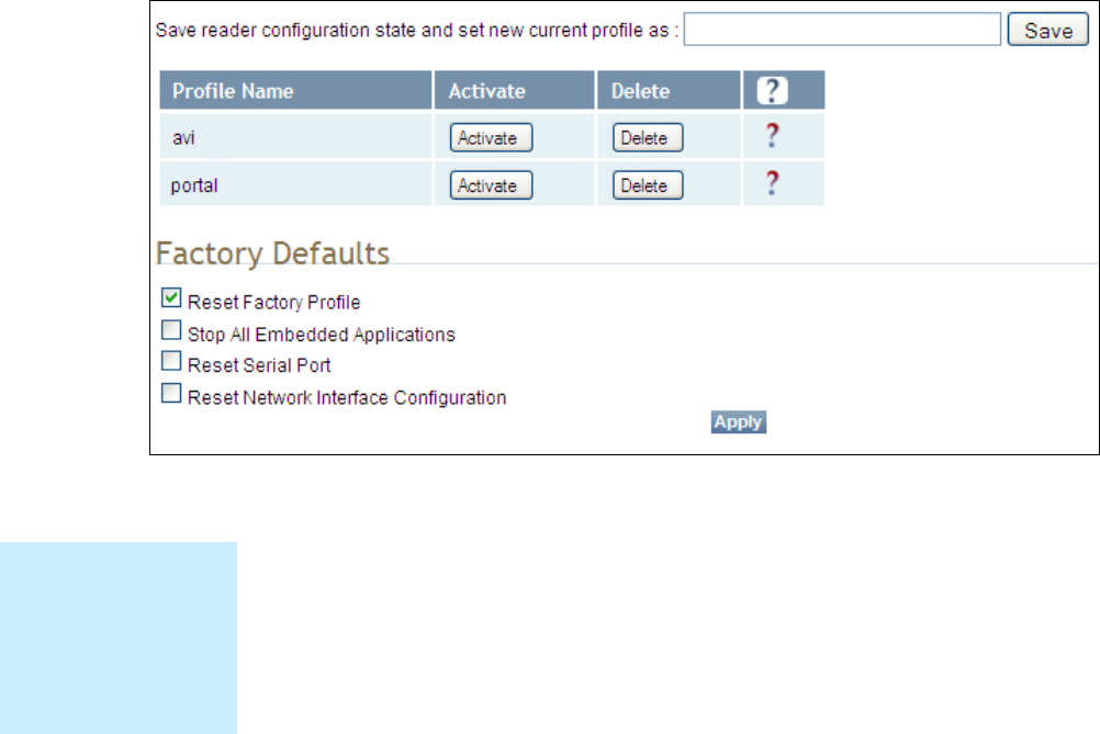
7.1.2. Manage Profiles
The reader’s configuration is stored in a profile. A profile contains the
setting of all the configuration variables in the reader. The reader can
support up to 8 unique profiles. Detailed information about reader profiles
is provided in Chapter 4 – Reader Behavior of the 3M Compact RFID
Reader 1000 Protocol Reference Guide.
The Manage Profiles page provides a list of all profiles stored in the reader.
Save a Profile
To save your current reader configuration under a new profile, enter a
profile name and press Save. The new profile will appear in the Profile
Name list. Profile names must consist of the characters A - Z, a - z, 0 - 9, '-'
or '_' and must be between 1 and 32 characters in length. The reader can
store up to 8 different profiles.
Profile Names
The profile name
factory is reserved
and cannot be used.
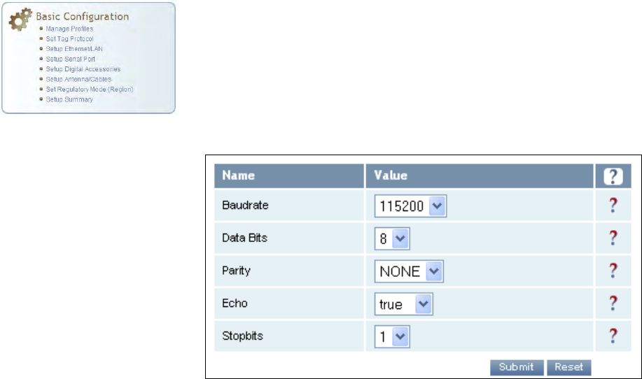
This profile is a read
only profile.

1 2 3 4 5 6 7 8 9 Reader Configuration Tool
50 3M Compact RFID Reader 1000 User’s Guide
Activate a Profile
To activate a previously saved profile, press the Activate button beside the
profile name. The selected profile will be loaded into the reader.
Delete a Profile
To delete a previously saved profile, press the Delete button beside the
profile name. This is a destructive operation. Once a profile is deleted, it
cannot be recovered.
Reset to Factory Default
In addition to managing reader profiles, you can also reset the reader back
to its factory default configuration. From the Profiles page select one or
more of the following:
Stop All Embedded Applications – This option terminates any
embedded applications currently running on the reader.
Reset Serial Port – This option resets the serial port configuration to
the factory default settings.
Reset Network Interface Configuration – This option resets the network
configuration to factory defaults.
NOTICE: Resetting the 3M Compact RFID Reader 1000 to Factory Default will reboot the reader.
1 2 3 4 5 6 7 8 9
Reader Configuration Tool
3M Compact RFID Reader 1000 User’s Guide 51
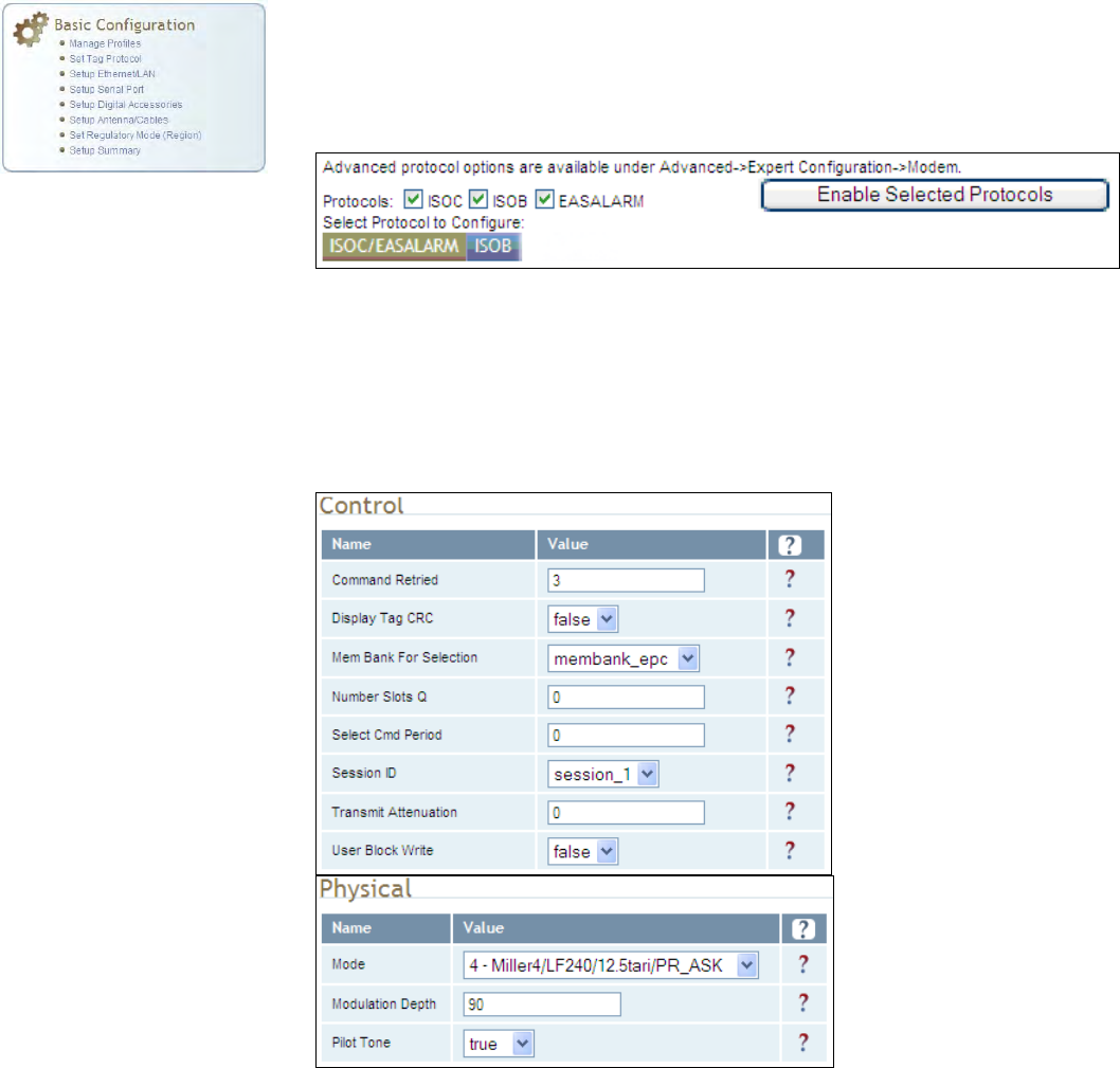
7.1.3. Set Tag Protocol
This Set Tag Protocol page consists of two forms. The first form (top) allows
you to select which type of tags the reader will acquire or the type of
protocol(s) to utilize on the air interface. Currently, the reader can operate
with either ISO18000-6B (ISOB), ISO18000-6C (ISOC), EASAlarm, or any
combination of the three.
Select the check box for the protocol(s) to enable and then press Enable
Selected Protocols to activate the protocol.
Click on a specific protocol to view the lower form. This form allows you to
configure various protocol level parameters. The protocol level parameters
are divided into two categories: control and physical. Control parameters
configure the protocol control. Physical parameters configure the physical
air interface for the protocol.
For detailed information on each of the Control and Physical parameters,
refer to Chapter 15 – Modem Namespace of the 3M Compact RFID Reader
1000 Protocol Reference Guide. Parameter descriptions are provided in
the modem.protocol.isoc.control and
modem.protocol.isoc.physical configuration variable sections.
1 2 3 4 5 6 7 8 9 Reader Configuration Tool
52 3M Compact RFID Reader 1000 User’s Guide
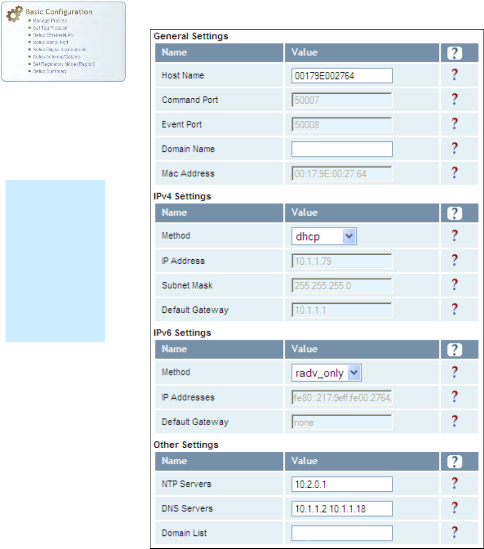
7.1.4. Setup Ethernet/LAN
The Setup Ethernet/LAN page allows you to configure the network interface
of the reader.
NOTE:
Always record the
IP, Mac, subnet,
and default
gateway addresses
for your readers
and keep this data
in a safe location.
You can use this
data to reconfigure
the network in the
event of application
failure or data loss.
1 2 3 4 5 6 7 8 9
Reader Configuration Tool
3M Compact RFID Reader 1000 User’s Guide 53
General Settings allow you to specify the host and domain name of the
reader. The Command and Event Ports are also shown and are read-only.
You can also select your domain name in this window.
IPv4/IPv6 Settings allow you to configure the reader’s IP address. If the
reader is to automatically acquire its IP address, subnet mask and default
gateway from a DHCP server, select Enable DHCP. To manually specify this
information, deselect Enable DHCP and fill in the desired IP address,
subnet mask and default gateway.
Other Settings allow you to configure the NTP servers the reader can
contact to obtain the current time, DNS servers the reader can contact for
domain name resolution, and the Domain list to resolve names to IP
addresses.
Enter all the required information and press Submit.
7.1.5. Setup Serial Port
The Setup Serial Port function allows you to configure the serial port
parameters. These parameters include:
Baud rate
Data bits
Parity
Echo
Stop bits
Use the pull-down menus to select a value and press Submit to update the
reader.
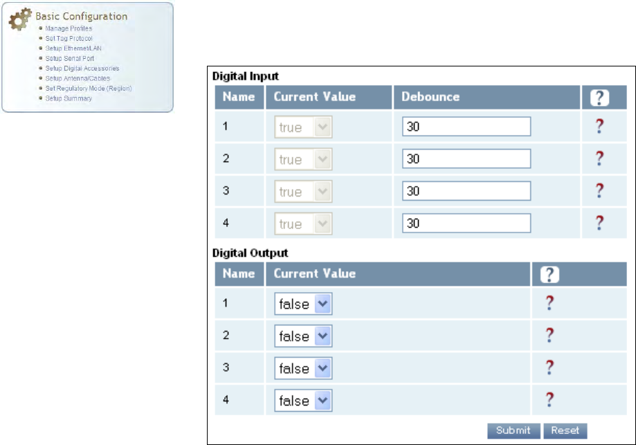
1 2 3 4 5 6 7 8 9 Reader Configuration Tool
54 3M Compact RFID Reader 1000 User’s Guide
7.1.6. Setup Digital Accessories
The Setup Digital Accessories function allows you to configure the Digital
Inputs and Outputs on the reader.
Digital Input
The status of the four digital input values (1–4) can be seen in this window.
The Current Value is not configurable and is shown as true or false. The
Debounce value can be set and is in milliseconds.
Digital Output
The output value for each digital output can be set to true or false. Press
the Submit button to send the appropriate commands to the reader to
update the digital inputs and outputs.
Refer to the 3M Compact RFID Reader 1000 Protocol Reference Guide for
more information on configuring the digital inputs and outputs.
1 2 3 4 5 6 7 8 9
Reader Configuration Tool
3M Compact RFID Reader 1000 User’s Guide 55
7.1.7. Setup Antenna/Cables
This page allows you to configure the reader’s antenna multiplexer
sequence as well as conducted power. For detailed description of each of
the antenna and cable variables, refer to Antenna Configuration in Chapter
4 – Reader Behavior of the 3M Compact RFID Reader 1000 Protocol
Reference Guide.
To configure an antenna, enter the antenna number in the Mux Sequence
field. The individual antenna Conducted Power fields will be activated in
the lower window. The current values will be displayed. Only those antennas
listed in the Mux Sequence will be shown. Also, you must set Conducted
Power to 0 in order to set or change the Attenuation, Cable Loss, or Gain.
NOTICE: This device has been designed to operate with no more than 1 Watt into the antenna and an
antenna gain of no more than 6 dBi, linear. Antenna having a higher gain is strictly prohibited
per FCC and Industry Canada regulations, unless power into the antenna is decreased to
compensate for the increased antenna gain.
To assist the installer with this regulatory compliance, the reader firmware
adjusts the actual conducted power level to the proper level, provided that
the Conducted Power setting is set to 0, and provided that the Gain, Gain
Units, Attenuation, and Cable Loss parameters are entered correctly for the
actual antenna and cables used in the installation.
To change the antenna parameters, enter the appropriate values for each
antenna parameter and press the Submit button to update the antenna
and cable configuration. Select the next antenna and repeat.
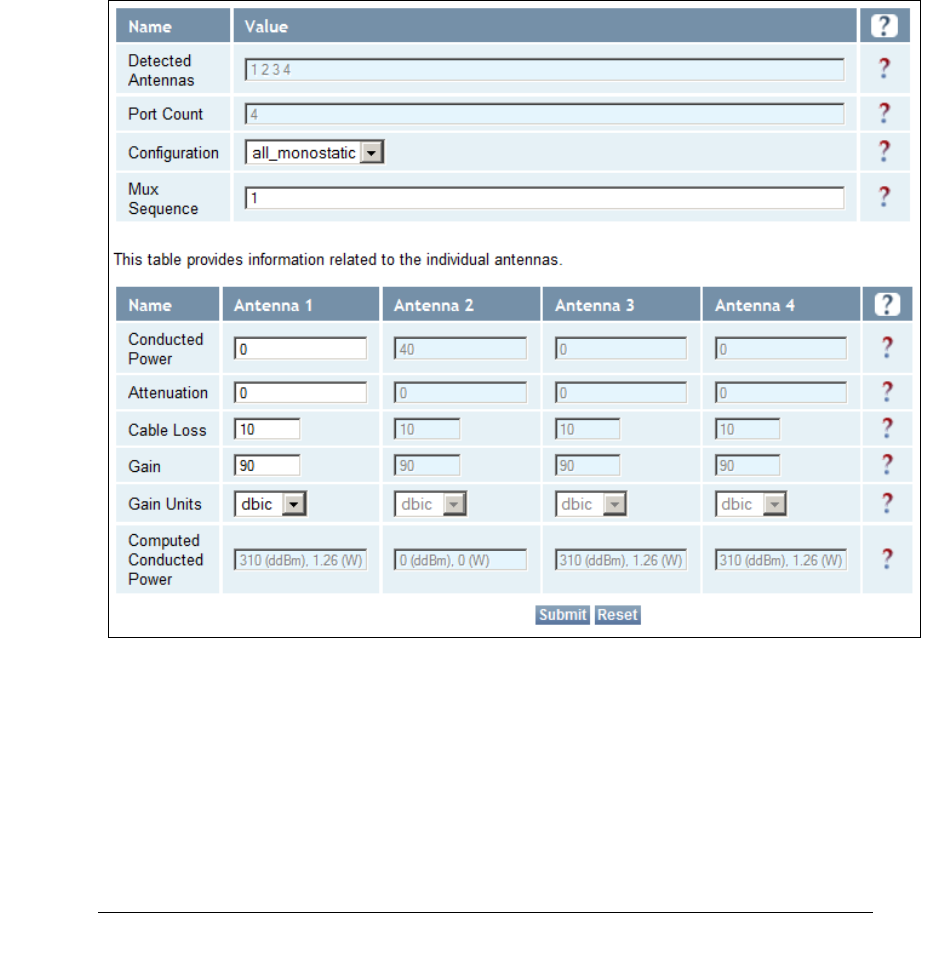
1 2 3 4 5 6 7 8 9 Reader Configuration Tool
56 3M Compact RFID Reader 1000 User’s Guide
ADDITIONAL ANTENNA NOTES:
1. The required antenna impedance is 50 ohms.
2. To reduce potential radio interference to other users, the antenna type and its gain should be so
chosen that the equivalent isotropically radiated power (EIRP) is not more than that required for
successful communication.
3. The installer of this radio equipment must ensure that the antenna is located or pointed such that
it does not emit an RF field in excess of Health Canada limits for the general population; consult
Safety Code 6, obtainable from Health Canada’s website at:
http://www.hc-sc.gc.ca/ewh-semt/pubs/radiation/radio_guide-lignes_direct/index-eng.php.
4. Additional details for the approved antennas for the 3M Compact RFID Reader 1000 can be found
in Section 9.1.7., 3M Compact RFID Reader 1000 Antenna Specifications.
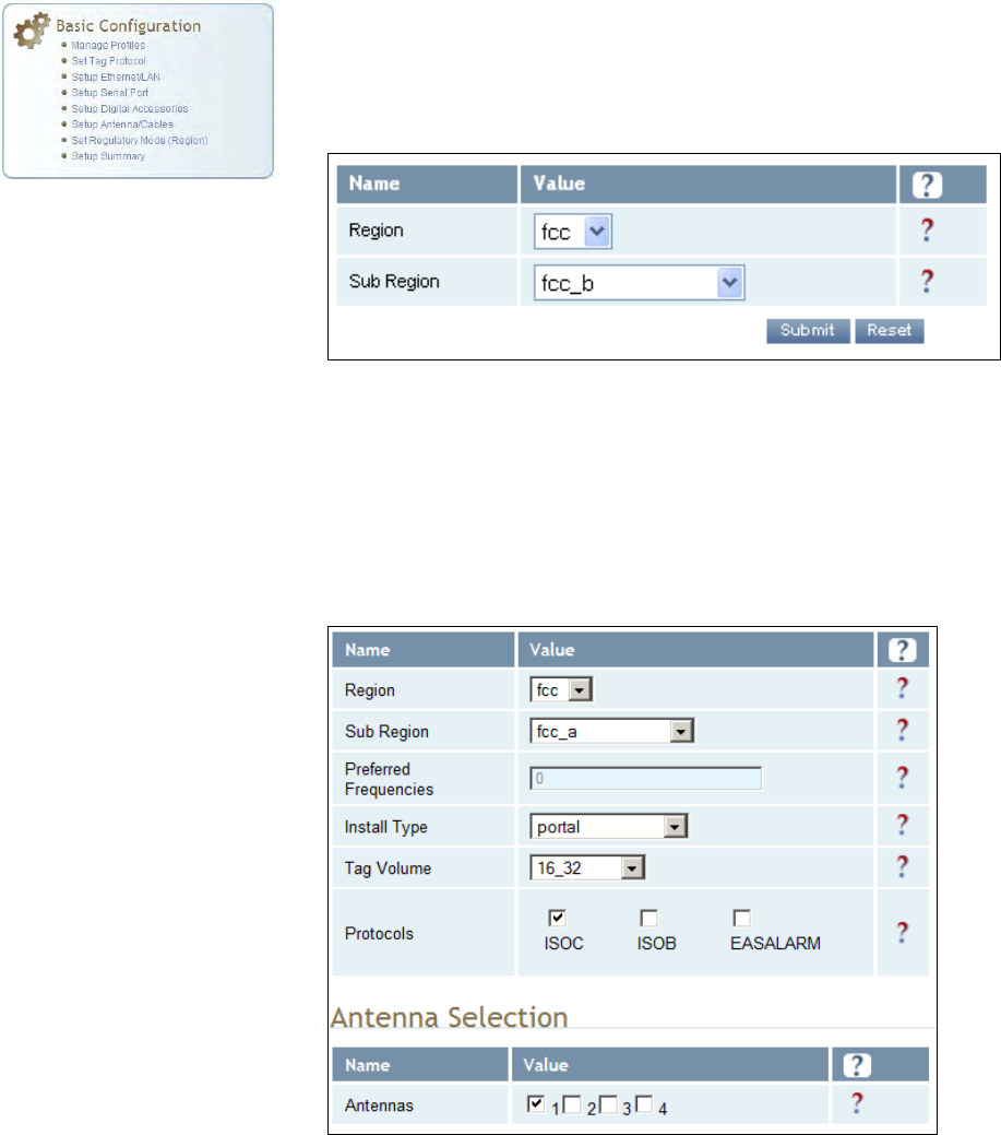
1 2 3 4 5 6 7 8 9
Reader Configuration Tool
3M Compact RFID Reader 1000 User’s Guide 57
7.1.8. Set Regulatory Mode (Region)
This page allows the user to configure the reader to meet the regulatory
requirements for the geographic region where the reader is deployed. The
sub-region sets the secondary regulatory mode for the geographic region
where the reader is deployed.
For detailed information on each of these parameters, refer to the 3M
Compact RFID Reader 1000 Protocol Reference Guide. Descriptions are
provided in the setup.region and setup.sub_region configuration
variable sections.
7.1.9. Setup Summary
This page allows you to quickly setup the basic operational parameters of
the reader.
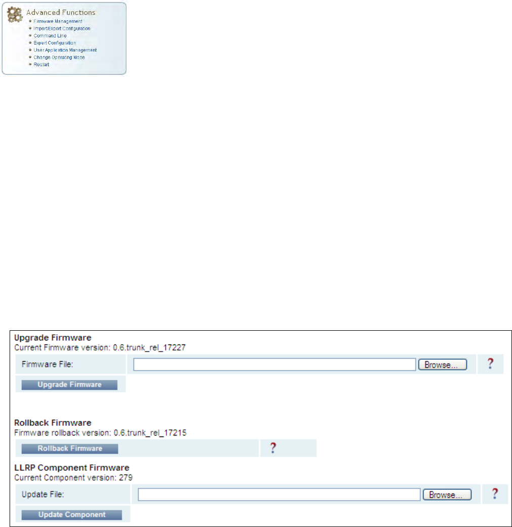
1 2 3 4 5 6 7 8 9 Reader Configuration Tool
58 3M Compact RFID Reader 1000 User’s Guide
7.2. Advanced Functions
With the Advanced Functions you can perform the following:
Firmware Management
Import/Export Configuration
Command Line operations
Expert Configuration
User Application Management
Change Operating Mode
Restart
7.2.1. Firmware Management
This page allows you to read the current firmware version, upgrade the
reader firmware files, or rollback to the previous firmware version.
To upgrade reader firmware, enter the name of the 3M provided firmware
file in the Firmware File field. Use the Browse button to help locate the file.
Once the filename is entered, press Upgrade Firmware. Note that this
function also upgrades the LLRP Component firmware.
To only upgrade the LLRP firmware, enter the name of the 3M provided
LLRP firmware file in the Update File field. Use the Browse button to help
locate the file. Once the filename is entered, press Update Component.
The Rollback Firmware button will roll back the firmware to the previous
version. This function does not rollback the LLRP component firmware. You
will need to update the component with a previous version.
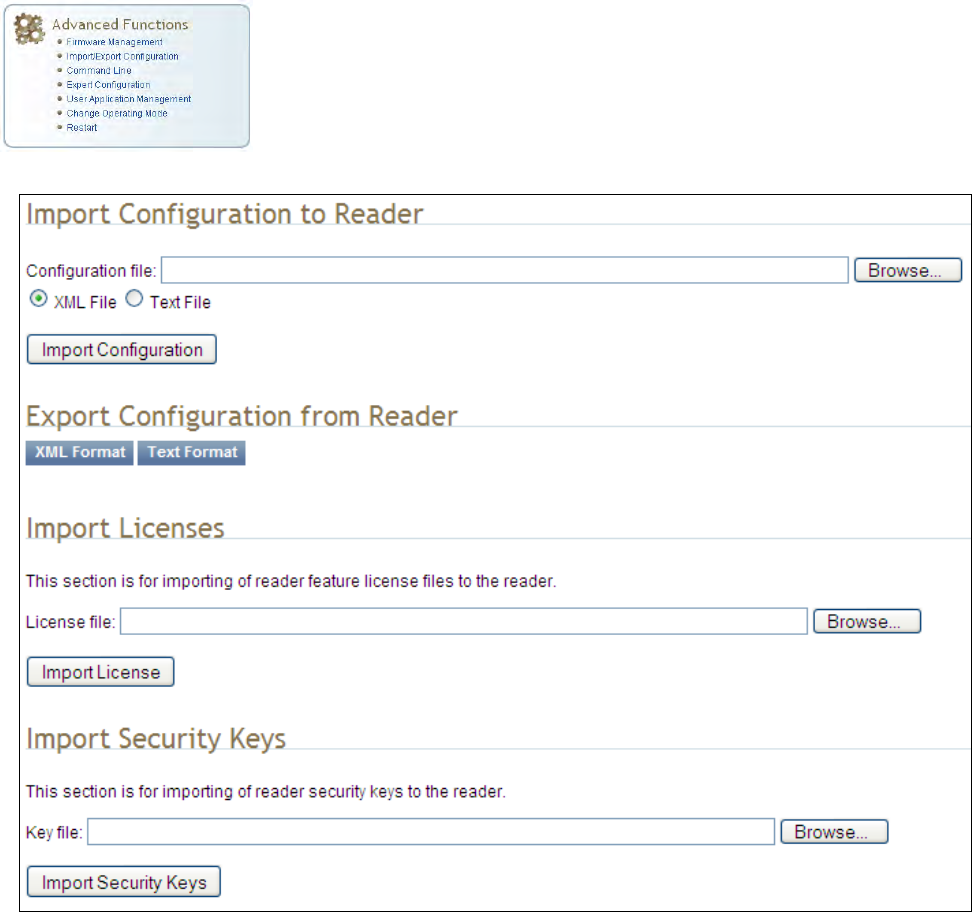
1 2 3 4 5 6 7 8 9
Reader Configuration Tool
3M Compact RFID Reader 1000 User’s Guide 59
7.2.2. Import/Export Configuration
This page allows you to transfer a reader configuration to or from your host
computer. This is useful for configuring a reader to a known state.
1 2 3 4 5 6 7 8 9 Reader Configuration Tool
60 3M Compact RFID Reader 1000 User’s Guide
Import Configuration to Reader
Enter the name of a saved configuration file in the Configuration file field.
Select the XML File option and press the Transfer Configuration to Reader
button to send the profile to the reader.
Export Configuration from Reader
This function is used to export the current reader settings for later
uploading. Press the XML Format button to view the XML file in the browser.
Save this file to your computer if you wish retain it for future.
If you wish to view the current configuration parameters for a reader, press
Text Format button.
Import Licenses
This function is used to import a feature license file. Navigate to the license
file and press Import License to load the file into the reader.
Import Security Keys
This function is used to import reader security keys to the reader. Navigate
to the key file and press Import Security Keys to load the file into the
reader.
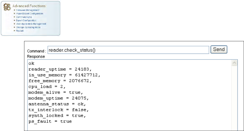
1 2 3 4 5 6 7 8 9
Reader Configuration Tool
3M Compact RFID Reader 1000 User’s Guide 61
7.2.3. Command Line
This page allows you to directly enter reader commands from your web
browser.To directly enter commands from the Command Line Interface
(CLI), refer to the 3M Compact RFID Reader 1000 Protocol Reference
Guide.
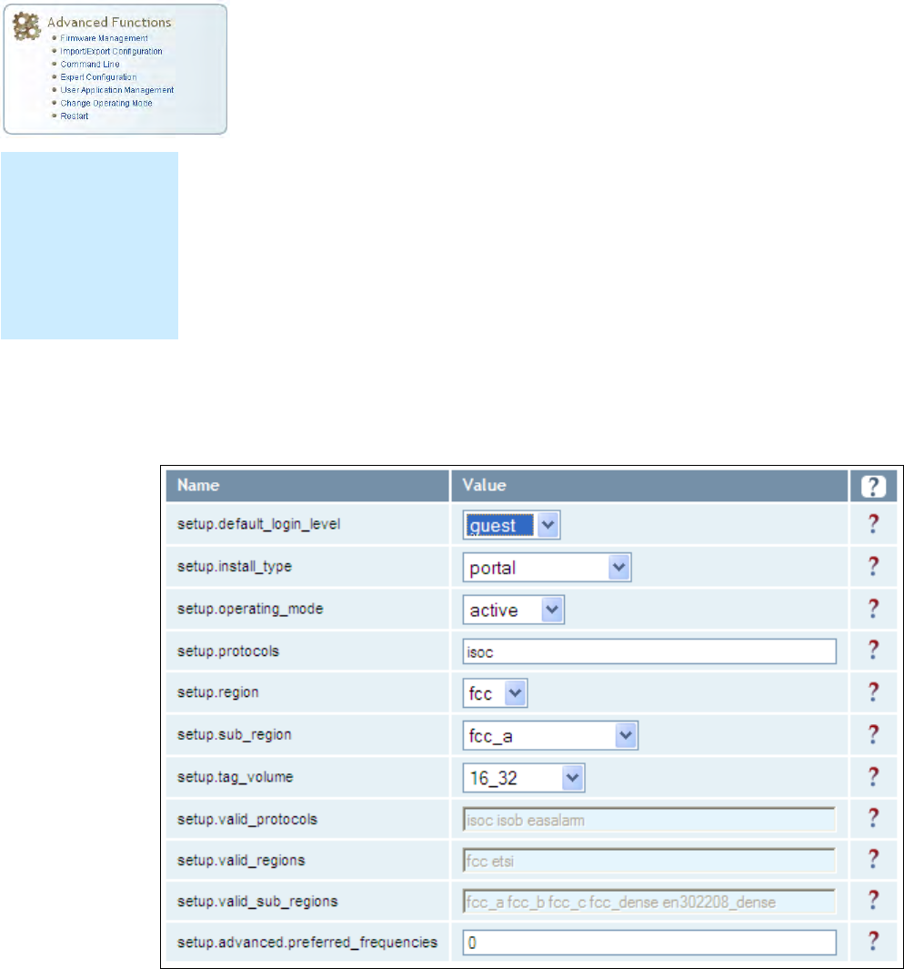
1 2 3 4 5 6 7 8 9 Reader Configuration Tool
62 3M Compact RFID Reader 1000 User’s Guide
7.3. Expert Configuration
The Expert Configuration functions allow you to configure low-level functions
within the reader. These functions should only accessed by expert users.
Expert configurations include:
Setup
Tag
Version
Information
Communication
Antennas
Digital I/O
Modem
7.3.1. Expert Configuration – Setup
This page allows you to set the basic operating parameters of the reader
including region, sub region, mode, and active protocols. You can also view
the valid protocols and regions.
NOTE
For details on
reader variables,
refer to the 3M
Compact RFID
Reader 1000
Protocol Reference
Guide.
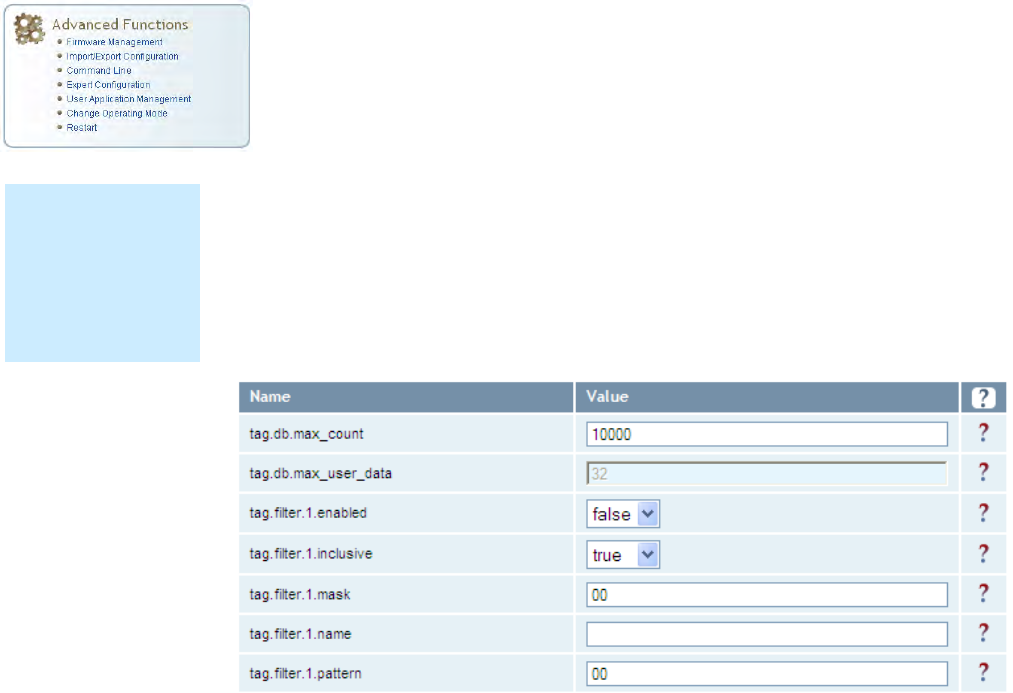
1 2 3 4 5 6 7 8 9
Reader Configuration Tool
3M Compact RFID Reader 1000 User’s Guide 63
7.3.2. Expert Configuration – Tag
This page allows you to configure how the reader reports tags.
The 1000 supports the ability to filter tags or eliminate tags from being
reported based on the conditions specified in the filter configuration
variables. The reader supports eight filters and each filter is specified by the
following configuration variables:
enabled – Enables or disables the filter.
inclusive – Indicates to either include tags that match (Inclusive) or
include tags that do not match (Exclusive) the tag filter.
mask – Mask (as an array of hex bytes) for the tag filter.
name – Name given to the tag filter
pattern – Pattern (as an array of hex bytes) for the tag filter
The following figure shows a small sample of the available variables.
NOTE
For details on tag
variables, refer to
the 3M Compact
RFID Reader 1000
Protocol Reference
Guide.
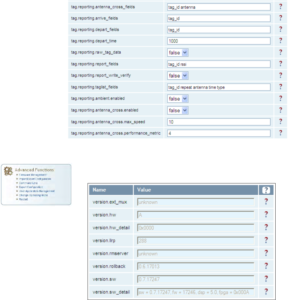
1 2 3 4 5 6 7 8 9 Reader Configuration Tool
64 3M Compact RFID Reader 1000 User’s Guide
7.3.3. Expert Configuration – Version
This page displays the version of reader hardware and reader software
within the reader. The version numbers are read-only and will be needed if
you contact 3M for technical support.
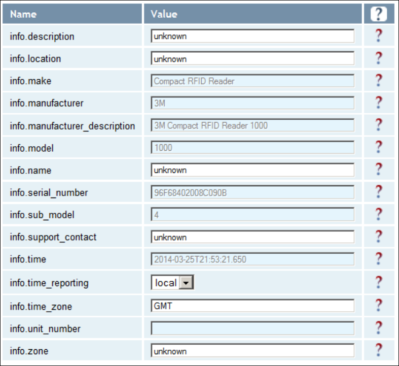
1 2 3 4 5 6 7 8 9
Reader Configuration Tool
3M Compact RFID Reader 1000 User’s Guide 65
7.3.4. Expert Configuration – Information
This page allows you to customize the reader’s identity. You can assign
each reader a name, description, location, and zone. You can also set how
the reader reports timestamps.
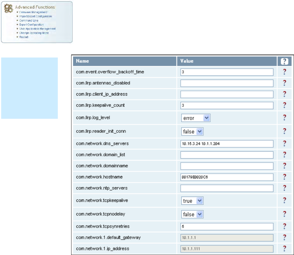
1 2 3 4 5 6 7 8 9 Reader Configuration Tool
66 3M Compact RFID Reader 1000 User’s Guide
7.3.5. Expert Configuration – Communication
This page allows you to customize the reader’s communication parameters.
Refer to the Setup Ethernet/LAN and Setup Serial Port sections for
additional information.
The following figure shows a portion of communication parameters
available on the reader.
NOTE
For details on
communication
parameters, refer
to the 3M Compact
RFID Reader 1000
Protocol Reference
Guide.
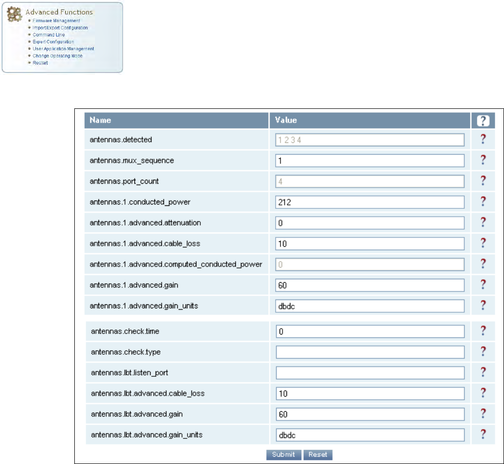
1 2 3 4 5 6 7 8 9
Reader Configuration Tool
3M Compact RFID Reader 1000 User’s Guide 67
7.3.6. Expert Configuration – Antennas
This page allows you to configure the properties of the reader’s antenna
configuration. For detailed description of each of the antenna and cable
variables, refer to the Antenna Configuration section in Chapter 4 – Reader
Behavior of the 3M Compact RFID Reader 1000 Protocol Reference Guide.
Enter the appropriate values for each antenna parameter and press the
Submit button to update the antenna and cable configuration.
The following figure shows only a small sample of the available antenna
configuration variables.
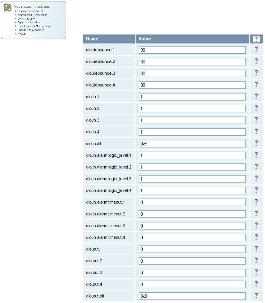
1 2 3 4 5 6 7 8 9 Reader Configuration Tool
68 3M Compact RFID Reader 1000 User’s Guide
7.3.7. Expert Configuration – Digital I/O
This page allows you to configure the digital inputs and output behavior. You
can set the digital input debounce time (in milliseconds), as well as the
input and output pin values. Refer to the 3M Compact RFID Reader 1000
Protocol Reference Guide for detailed information on each of these
variables.
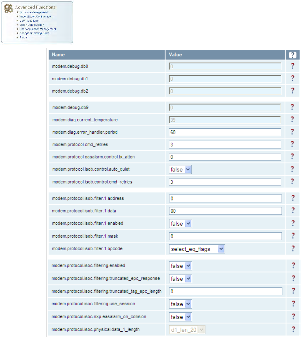
1 2 3 4 5 6 7 8 9
Reader Configuration Tool
3M Compact RFID Reader 1000 User’s Guide 69
7.3.8. Expert Configuration – Modem
This page allows you to set the reader’s modem control variables. These
variables control functions such as EPC link, modulation depth, return link
frequency, and others. Refer to the 3M Compact RFID Reader 1000
Protocol Reference Guide for detailed information on each of these
variables. The following figure shows only a small sample of the available
modem configuration variables.
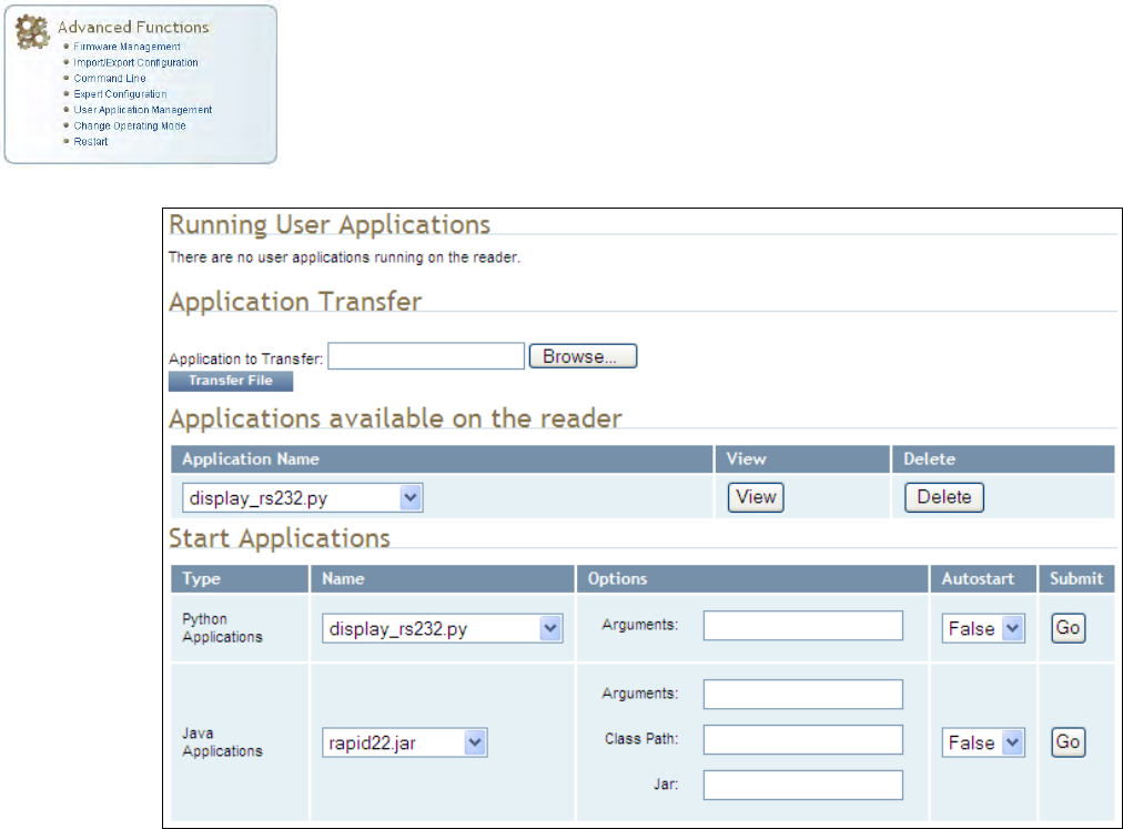
1 2 3 4 5 6 7 8 9 Reader Configuration Tool
70 3M Compact RFID Reader 1000 User’s Guide
7.4. User Application Management
This page lists any user applications currently available on the reader and if
any applications are running. This page also allows you to upload
applications to the reader.
Running User Applications – Lists any user applications currently
running on the reader. The application name, process ID, configuration,
and status are provided. Controls are provided to view the application
file and stop the application.
Application Transfer – This function allows you to load custom user
applications onto the reader.
Applications available on the reader – This function allows you to view a
list of all user applications stored on the reader. Controls are provided
to view the application and delete it from the reader.
Start Applications – This function allows you to start Python and Java
applications.
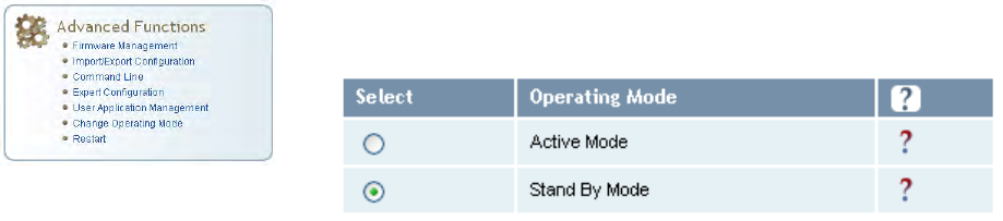
1 2 3 4 5 6 7 8 9
Reader Configuration Tool
3M Compact RFID Reader 1000 User’s Guide 71
7.5. Change Operating Mode
This page allows you to configure the operational mode of the reader.
The reader supports the following operational modes:
Active Mode - Reader is continuously attempting to singulate tags and
automatically reports any singulated tag via an asynchronous event
notification on the event channel.
Stand By Mode - Reader is not transmitting any energy, unless
processing a tag related command. The RF transmitter is enabled at the
beginning of the command processing, any protocol operations required
for the command are performed, and then the RF transmitter is turned
back off.
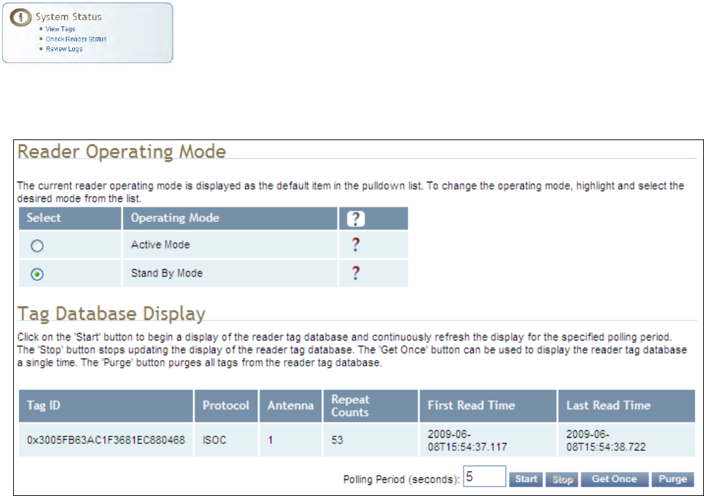
1 2 3 4 5 6 7 8 9 Reader Configuration Tool
72 3M Compact RFID Reader 1000 User’s Guide
7.6. View Tags
All tags read by the reader are stored in a database on the reader. This
page allows you to view the tags in the database as well as change the
current Operating Mode (Active or Stand By).
Press Start to begin displaying the tag database. This page is automatically
refreshed every five seconds. Press Get Once to update the database one
time (refresh is off). Press Purge to purge all tags from the database.
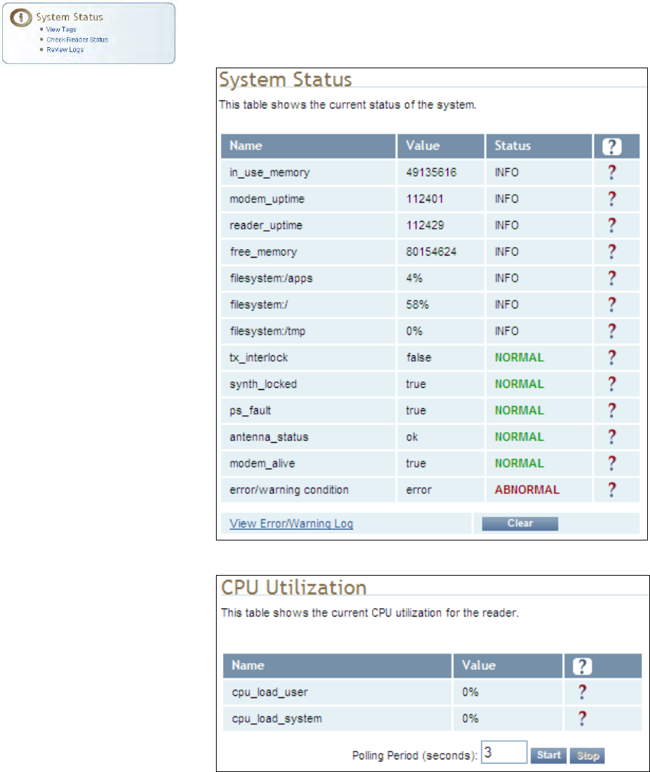
1 2 3 4 5 6 7 8 9
Reader Configuration Tool
3M Compact RFID Reader 1000 User’s Guide 73
7.7. Check Reader Status
This page allows you to view the reader/system status, CPU utilization,
services, and licensed features. This information can be used by 3M
Technical Support to verify reader operation.
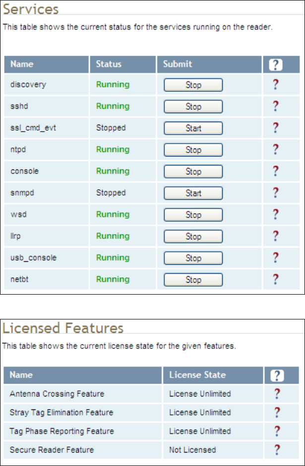
1 2 3 4 5 6 7 8 9 Reader Configuration Tool
74 3M Compact RFID Reader 1000 User’s Guide
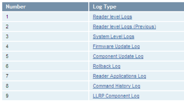
1 2 3 4 5 6 7 8 9
Reader Configuration Tool
3M Compact RFID Reader 1000 User’s Guide 75
7.8. Review Logs
This page allows you to view the reader logs. These logs can be used by 3M
Technical Support to verify reader operation. The reader logs include:
Reader level Logs – System level reader operation
System Level Logs – Linux logs
Firmware Update Log – Status of last firmware update
Component Update Log – status of last component firmware update
Rollback Log – Previous firmware
Reader Applications Log – User application logs
Command History Log – Recent commands sent to the reader.
LLRP Component Log – LLRP service

1 2 3 4 5 6 7 8 9 Configuring Digital I/Os
76 3M Compact RFID Reader 1000 User’s Guide
8 Configuring Digital Inputs and Outputs
8.1. Digital Inputs
The digital inputs (DIN1 – DIN4) can be used as general purpose inputs or
to trigger the reader for tag reading. Unused or open digital inputs are
floating inside the reader.
To activate the input, pull it low (0 Vdc) with an external device or
connection to ground that can sink 2.5 mA. No voltage higher than +24 Vdc
or lower than 0 Vdc should ever be connected to the input. See Figure 5 for
an example of a typical motion sensor installed as a tag read trigger device.
8.2. Digital Outputs
The digital outputs (DOUT1 – DOUT4) can be used as general purpose
outputs, to indicate tag reading activity, or to indicate the reader is
transmitting (RF On). Digital outputs can be pulled high.
No voltage higher than +40 Vdc or lower than 0 Vdc should ever be
connected to a digital output. The reader activates the output by pulling it
low (0 Vdc) and can sink current such that power dissipation is ≤ 1W.
8.3. Low Latency Digital Input/Output Operation
The 1000 is equipped with low-latency digital inputs and outputs. The
inputs (3 and 4) can be used by the modem to trigger low-latency events.
Two commands control these inputs as follows:
modem.dio.in.X.positive_level = Y -- if X goes high, it triggers Y
modem.dio.in.X.negative_level = Y -- if X goes low, it triggers Y
where Y can be:
NOOP (default)
ACTIVE_MODE
STANDBY_MODE
TOGGLE_MODE
ONE_ROUND (performs one inventory round, nonblock)
RUN_SCRIPT (runs series of modem commands, see the following)
Digital I/O Module
An optional Digital
I/O Module is
available for the
3M Compact RFID
Reader 1000.
Refer to Appendix A
for more
1 2 3 4 5 6 7 8 9
Configuring Digital I/Os
3M Compact RFID Reader 1000 User’s Guide 77
Any time the RUN_SCRIPT operation is invoked, the reader will sequence
through a maximum of 10 modem commands as follows:
modem.dio.in.X.script.num_cmds = Q
modem.dio.in.X.script.cmd1 = Z
modem.dio.in.X.script.cmd2 = Z
modem.dio.in.X.script.cmd3 = Z
.
.
.
modem.dio.in.X.script.cmd10 = Z
where:
Q is the number of commands. Q can be 0 to 10 (maximum 10 modem
commands).
Z can be any modem command
An event event.response.modem_dio_scripts dio_in=*,
cmdnum=*, resp=*** is generated after each modem command.
Digital outputs 3 and 4 can be driven by modem after setting the following:
dio.control.X = modem
Actions that triggered the output can be defined by:
modem.dio.out.X.op = Y
where Y can be:
NOOP (default)
END_OF_ROUND (generates a pulse at end of each inventory round)
ACTIVE_MODE (triggers high in active mode)
SCRIPT_RUNNING (triggers high when digital input io triggered
script is running)
ANTENNA_FAILURE (triggers high in antenna failure state)
ERROR (generates a pulse when an error occurs)
WARNING (generates a pulse when an warning occurs)
All output (level/pulse) polarity is defined by:
modem.dio.out.X.polarity = Z
where Z can be:
POSITIVE (default)
NEGATIVE
All pulse width (in μSec) is defined by:
1 2 3 4 5 6 7 8 9 Configuring Digital I/Os
78 3M Compact RFID Reader 1000 User’s Guide
modem.dio.out.X.pulse_width –(default 100 μSec)
Example (Input)
The following example triggers a series of modem commands, when DIO
input 4 goes high.
modem.dio.in.4.positive_level = RUN_SCRIPT
modem.dio.in.4.script.num_cmds = 3
modem.dio.in.4.script.cmd1 = "modem.antennas.perform_check()"
modem.dio.in.4.script.cmd2 = "modem.diag.current_temperature"
modem.dio.in.4.script.cmd3 = "modem.stats.tag_read"
Example (Output)
In the following example, DIO output 3 will trigger low when the reader is in
active mode.
dio.control.3 = modem
modem.dio.out.3.op = ACTIVE_MODE
modem.dio.out.3.polarity = NEGATIVE
8.4. Digital I/O Monitoring and Control Scripts
Several digital I/O monitoring and control scripts are provided with the
reader to allow you to monitor the digital I/Os and take specific actions.
These Python application scripts can be used as is or modified to suit your
particular application. For detailed information on loading Python scripts,
refer to Chapter 5 – Embedded Reader Applications of the 3M Compact
RFID Reader 1000 Protocol Reference Guide.
8.4.1. scan_trigger.py
This routine monitors the state of the digital input pin specified as the input
parameter. If the state of the pin is low, the operating mode is set to
standby. If the I/O pin state changes to high, the operating mode is set to
active.
Inputs: <pin> – (optional) Input pin number (1–4). Default is digital
in 1.
<trigger logic level> –(optional) 0 or 1. Default is trigger on 1.
Examples:
scan_trigger.py Monitors digital input pin 1
scan_trigger.py 1 Monitors digital input pin 1
scan_trigger.py 4 Monitors digital input pin 4
scan_trigger.py 3 0 Monitors digital input pin 3, trigger on 0
1 2 3 4 5 6 7 8 9
Configuring Digital I/Os
3M Compact RFID Reader 1000 User’s Guide 79
8.4.2. scan_trigger_timer.py
This routine monitors the I/O pin. When the pen goes high, the timer is
started and the operating mode is set to active. While the timer is running,
I/O pin state changes are ignored. When the timer expires, the operating
mode is set to standby. The minimum value for the timer is 10 milliseconds
(ms).
Inputs: <pin> – (optional) Output pin number (1–4). Default is output 1.
<time> – (optional) Time, in ms for timer to run. Default is 1000 ms.
<trigger logic level> –(optional) 0 or 1. Default is trigger on 1.
Examples:
scan_trigger_timer.py Monitors input 1, timer 1000 ms,
trigger on 1
scan_trigger_timer.py 2 Monitors input 2, timer 1000 ms,
trigger on 1
scan_trigger_timer.py 4 2000 Monitors input 4, timer 2000 ms,
trigger on 1
scan_trigger_timer.py 3 4000 0 Monitors digital input 3, timer
4000 ms, trigger on 0
8.4.3. signal_read.py
This routine will turn on a digital output if a tag is successfully read. The
optional output pin number can be specified on the command line. If not
specified, output pin 1 is used. The output pin will remain high for n ms,
where n is either the default of 1000 ms, or the value supplied on the
command line. Minimum value for n is 10 ms.
Inputs: <pin> – (optional) Output pin number (1–4). Default is output 1.
<time> – (optional) Time, in ms, to keep the output high. Default is
1000 ms (1 sec).
<logic level> – (optional) Logic level for digital out On. 0 or 1. Default is 1
(On).
Examples:
signal_read.py Turns on output 1 for 1000 ms on tag reads
signal_read.py 2 Turns on output 2 for 1000 ms on tag reads
signal_read.py 1 5000 Turns on output 1 for 5000 ms on tag reads
signal_read.py 1 500 Turns on output 1 for 500 ms on tag reads
signal_read.py 1 800 0 Turns on digital output 1,logic level 0, for
800 ms on tag reads
1 2 3 4 5 6 7 8 9 Configuring Digital I/Os
80 3M Compact RFID Reader 1000 User’s Guide
8.4.4. signal_read_crc_error.py
This routine will turn on a digital output if a tag read CRC error is detected.
The output pin number can be specified on the command line. If not
specified, output pin 1 is used. The output pin will remain high for n ms,
where n is either the default of 1000 ms or the value supplied on the
command line. Minimum value for n is 10 ms.
Inputs: <pin> – (optional) Output pin number (1–4). Default is output 1.
<time> – (optional) Time, in ms, to keep the output high. Default is
1000 ms.
<logic level> – (optional) Logic level for digital out On. 0 or 1. Default is 1
(On).
Examples:
signal_read_crc_error.py Turns on output 1 (logic level
1=on), for 1000 ms on tag read CRC error.
signal_read_crc_error.py 2 Turns on output 2 (logic level
1=on), for 1000 ms on tag read CRC error.
signal_read_crc_error.py 1 5000 Turns on output 1 (logic
level 1=on), for 5000 ms on tag read CRC error.
signal_read_crc_error.py 1 500 Turns on output 1 (logic
level 1=on) for 500 ms on tag read CRC error.
signal_read_crc_error.py 1 800 0 Turns on output 1 (logic
level 0=on), for 800 ms on tag CRC error.
8.4.5. rf_mon.py
This routine will monitor the state of the transmitter. If the transmitter is on,
it sets the appropriate output pin high. If low, it sets the output pin low.
Inputs: <pin> – (optional) Output pin number (1–4). Default is output 1.
<logic level> – (optional) Logic level for digital out On. 0 or 1. Default is 1
(On).
Examples:
rf_mon.py Monitors RF status, set/clear output 1 on change, logic
level 0 for on
rf_mon.py 1 Monitors RF status, set/clear output 1 on change, logic
level 0 for on
rf_mon.py 2 Monitors RF status, set/clear output 2 on change, logic
level 0 for on
rf_mon.py 3 0 Monitors RF status, set/clear output 3 on change, logic
level 1 for on
1 2 3 4 5 6 7 8 9
Configuring Digital I/Os
3M Compact RFID Reader 1000 User’s Guide 81
8.5. Digital Input Alarm Generation
The 1000 can be configured to generate an alarm when a digital input is
disconnected or sensor failure is detected. The alarm is triggered when the
signal level on the digital input stays in the specified state longer than the
specified alarm timeout. This behavior can be configured independently for
each digital input.
The configuration variable dio.in.alarm.logic_level.<N> (where <N> is
1,2,3,4) sets whether the alarm is coupled to a input logic level of 0 (low) or
1 (high).
The configuration variable dio.in.alarm.timeout.<N> (where <N> is 1,2,3,4)
sets the amount of time, in seconds, to wait for a signal state change. A
value of 0 (default) disables alarm generation.
The digital input logic level is used along with the corresponding digital input
pin timeout value to determine if an alarm (in the form of an event) should
be generated. If a timeout value is set, the input pin is monitored. If the
input pin value does not change during the timeout period AND the input
pin value matches the alarm logic level, the event
event.dio.in.alarm.timeout.n (where n is the pin number) is generated. This
alarm event generation can be helpful in alerting to the loss of digital inputs
to the reader.
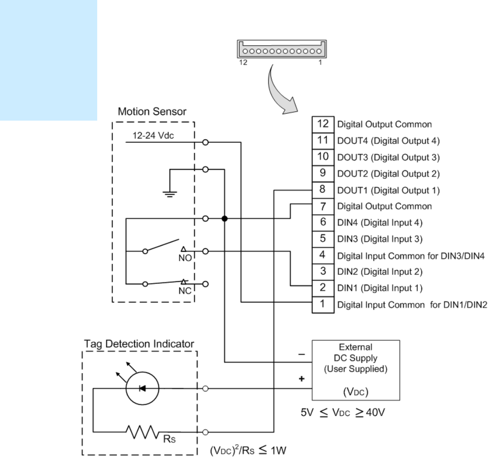
1 2 3 4 5 6 7 8 9 Configuring Digital I/Os
82 3M Compact RFID Reader 1000 User’s Guide
8.6. Digital I/O Hardware Connection
Figure 5 shows a typical sensor/indicator connection to the digital I/Os.
Figure 5 Example Motion Detector and Indicator connected to the Digital I/O
External DIO
Interface Module
An external DIO
interface module is
available for the
3M Compact RFID
Reader 1000. See
the Appendix in this
User’s Guide for
more information.

1 2 3 4 5 6 7 8 9 Safety Instructions
3M Compact RFID Reader 1000 User’s Guide 83
9 Specifications
9.1.1. Reader Specifications
Frequency 865– 868 MHz (ETSI)
902 – 928 MHz (FCC Part 15)
RF Power 10 mW – 1W conducted (30 dBm)
Power Consumption 10W (typical while idle)
18W (typical at 1W conducted output power)
20W (maximum at 1W conducted output power)
Connections RS-232, Digital I/O, Ethernet LAN
Input Voltage 24 Vdc
Input Current 1.5A maximum at 24 Vdc
NOTICE: If DC power is disconnected from the reader, wait a minimum of 30 seconds before
reapplying power.
ActiveModeDCCurrentDrawvsTransmittedPower
0.4
0.5
0.6
0.7
0.8
0.9
1
10 15 20 25 30 35
TransmittedPower(dBm)
DCCurrentdraw(A)
+60degC
+25degC
‐20degC
Figure 6 Typical Power Consumption versus Conducted Output Power at 910 MHz

1 2 3 4 5 6 7 8 9
Safety Instructions
84 3M Compact RFID Reader 1000 User’s Guide
9.1.2. Environmental Specifications
Operating Temperature -4° F to 131° F (-20° C to 55° C)
Storage Temperature -40° F to 185° F (-40° C to 85° C)
Maximum Shock 1 foot (0.3 meter) drop to any corner
Relative Humidity 5% to 95% non-condensing
Case Material Aluminum
Case Dimensions 9.72 x 7.25 x 2.2 in (246.7 x 184.2 x 55.6 mm)
Weight 4.5 lbs (2.1 kg)
NOTICE For outdoor reader applications, additional packaging is required to ensure weather
resistance. Contact your 3M Representative for more information.
9.1.3. AC/DC Power Adapter Specifications
Part Number GS90A24-P1** (FCC use) GS120A24-P1**(ETSI use)
Manufacturer Mean Well Mean Well
Input Voltage 90 to 264 VAC 90 to 264 VAC
Input Current 2A, typ. (115VAC);
1A, typ. (230VAC)
1.4A, typ. (115VAC);
0.7A, typ. (230VAC)
Input Frequency 47 – 63 Hz 47 – 63 Hz
Output Voltage 24 VDC 24 VDC
Output Current 3.75 A, maximum 5.0 A, maximum
Output Power 90 W, maximum 120 W, maximum
9.1.4. RS-232 Specifications
Connector DB-9S
Baud rate 1200 - 115200 (Default = 115200)
Parity None
Data bits 8
Stop bits 1
Signals Pin 1
Pin 2
Pin 3
Pin 4
Pin 5
Pin 6
Pin 7
Pin 8
Pin 9
NC
TXD
RXD
DTR (Connected to Pin 6-DSR)
GND
DSR (Connected to Pin 4-DTR)
CTS
RTSA
NC

1 2 3 4 5 6 7 8 9 Safety Instructions
3M Compact RFID Reader 1000 User’s Guide 85
9.1.5. Digital Input/Output Specifications
Connector Phoenix Contact PN 1881422
Input 5 to 24 Vdc, 1 to 5 mA, Optically Isolated
Output Open Collector (3 to 40 V, 100 mA Max)
Signals Pin 1 –
Digital Common Voltage Reference for DIN1/DIN2
Pin 2 – DIN1 (Digital Input 1)
Pin 3 – DIN2 (Digital Input 2)
Pin 4 –- Digital Common Voltage Reference for DIN3/DIN4
Pin 5 – DIN3 (Digital Input 3)
Pin 6 – DIN4 (Digital Input 4)
Pin 7 – Digital Common Ground
Pin 8 – DOUT1 (Digital Output 1)
Pin 9 – DOUT2 (Digital Output 2)
Pin 10 – DOUT3 (Digital Output 3)
Pin 11 – DOUT4 (Digital Output 4)
Pin 12 – Digital Common Ground
NOTE: Pins 7 and 12 can be used for both inputs and outputs.
Pin 1 is on the left when facing the end of the reader.
9.1.6. Ethernet LAN Specifications
Connector RJ-45
Ethernet 10/100 BaseT
Indicators Yellow - Indicates link is operational
Green - Indicates network traffic detected.
Signals Pin 1 –
TXD+ (Transmit Data +)
Pin 2 – TXD- (Transmit Data -)
Pin 3 – RXD+ (Receive Data +)
Pin 4 – NC
Pin 5 – NC
Pin 6 – RXD- (Receive Data -)
Pin 7 – NC
Pin 8 – NC

1 2 3 4 5 6 7 8 9
Safety Instructions
86 3M Compact RFID Reader 1000 User’s Guide
9.1.7. 3M Compact RFID Reader 1000 Antenna Specifications
Please refer to the 3M Antenna Application Guide for detailed specifications
and application information for 3M Toll Compact Reader 1000 antennas.
Part Number MT-262006/NRH/K
(3M SKU: 78-0060-1045-4)
MT-242048/NRH
(3M SKU: 78-0060-1047-0)
Frequency range 902–928 MHz 865–956 MHz
Antenna type Patch Patch
Impedance 50 Ω, nominal 50 Ω, nominal
Gain 9 dBic (min)
10 dBic (max)
865-870 MHz: 7.0 dBic (min)
8.5 dBic (max)
902-928 MHz: 7.5 dBic (min)
8.5 dBic (max)
950-956 MHz: 7.0 dBic (min)
8.0 dBic (max)
Beam width (3 dB) 63°, typical 70°, maximum
Polarization RHCP RHCP
F/B ratio -20 dB, typical
-18 dB, maximum -20 dB, maximum
Side lobes level -16 dB, maximum n/a
Power input 38 dBm (6 W) 38 dBm (6 W)
VSWR 1.5:1 (max) 1.2:1 (typ)
1.35:1 (max)
Connector type N type Female (Jack) N type Female (Jack)
NOTICE: This device has been designed to operate with no more than 1 Watt into the antenna and an
antenna gain of no more than 6 dBi, linear. Antenna having a higher gain is strictly prohibited
per FCC and Industry Canada regulations, unless power into the antenna is decreased to
compensate for the increased antenna gain. The required antenna impedance is 50 ohms.
To reduce potential radio interference to other users, the antenna type and its gain should be
so chosen that the equivalent isotropically radiated power (EIRP) is not more than that
required for successful communication.
The installer of this radio equipment must ensure that the antenna is located or pointed such
that it does not emit an RF field in excess of Health Canada limits for the general population;
consult Safety Code 6, obtainable from Health Canada’s website at:
http://www.hc-sc.gc.ca/ewh-semt/pubs/radiation/radio_guide-lignes_direct/index-eng.php
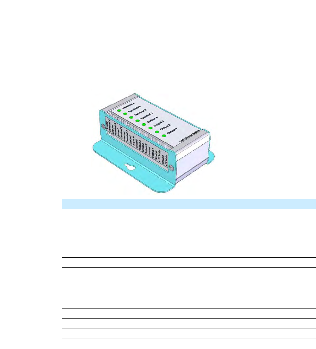
Appendix A Digital I/O Interface Module
3M Compact RFID Reader 1000 User’s Guide 87
A Digital Input/Output Interface Module
NOTE: The DIO Interface Module may not be available for some models.
Please contact your 3M Representative for availability.
The 3M DIO Interface Module provides an easily accessible interface to the
reader’s four digital inputs and four digital outputs. Screw terminals provide
secure signal connections and eight LEDs indicate I/O activation. The
interface also provides +12 Vdc, +15 Vdc, and ground.
The module connects to the reader’s existing digital I/O connector and 15
Vdc power connector. Reader power passes through the interface module.
Term Signal Name D-Sub Pin Description
1, 3, 5, 9, 13,
15, 17, 19
GND 7,12,13,14,15 Ground
2 Terminal4 6 Digital Input 4 – optically isolated
4 Terminal3 5 Digital Input 3 – optically isolated
6 Terminal2 3 Digital Input 2 – optically isolated
7 GND 7,12,13,14,15 Ground
8 Terminal1 2 Digital Input 1 - optically isolated
10 Output4 11 Digital Output 4 - open collector
11 GND 7,12,13,14,15 Ground
12 Output3 10 Digital Output 1 - open collector
14 Output2 9 Digital Output 0 - open collector
16 Output1 8 Digital Output 1 – open collector
18 +15 Volts — +15Vdc
20 +12 Volts — +12 Vdc (from onboard regulator)

Appendix A Digital I/O Interface Module
88 3M Compact RFID Reader 1000 User’s Guide
A.1. Digital Inputs
The digital inputs (Terminal 1–Terminal 4) can be used as general purpose
inputs or to trigger the reader for tag reading. Unused or open digital inputs
are pulled high to +15 Vdc inside the reader. The DIO interface module has
an LED provided in series with each digital input line that lights when the
input is activated by an external source.
To activate the input, pull it low (0 Vdc) with an external device or
connection to ground that can sink 2.5 mA. No voltage higher than +15 Vdc
or lower than 0 Vdc should ever be connected to a digital input. Examples of
typical motion detectors installed as tag read trigger devices are shown in
diagrams later in this appendix.
Configuring the reader for digital input triggered reads is described in
Chapter 7 – Configuring Digital Inputs and Outputs.
A.2. Digital Outputs
The digital outputs (Output 1 – Output 4) can be used as general purpose
outputs, to indicate tag reading activity, or to indicate the reader is
transmitting (RF On). Digital outputs are pulled high in the DIO interface
module to +12 Vdc through an LED and a series resistor. The LED is in
parallel with the output line and lights up when the output is activated by
the reader. Refer to the following figure for a typical light stack installed as a
tag read indicator.
Caution: No voltage higher than +15 Vdc or lower than 0 Vdc should ever be connected
to a digital output. The reader activates the output by pulling it low (0 Vdc) and
can sink up to 100 mA per line.
Configuring the reader for digital output activation on tag reads is described
later in this appendix.
A.3. Input Power and Voltage Regulator
Input power is supplied by a +15 Vdc power adapter. The onboard +12 Vdc
regulator supplies +12 Vdc power to the board and to terminal 20.
The regulator has a tolerance of +/-5% and is capable of supplying 100 mA.
The total LED draw is 10 mA. Therefore, any total current draw for the board
should not exceed 75 mA.
NOTE: Power to the reader is supplied by a separate 100-240 Vac to 24 Vdc
power adapter.
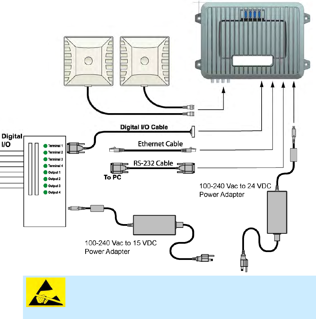
Appendix A Digital I/O Interface Module
3M Compact RFID Reader 1000 User’s Guide 89
ATTENTION 3M Compact RFID Reader 1000 antenna ports may be susceptible to
damage from static discharge or other high voltage. Use proper
Electrostatic Discharge (ESD) precautions to avoid static discharge
when handling or making connections to the 1000 antenna or
communication ports. Equipment failure can result if the antenna or
communication ports are subjected to ESD.
A.4. Connecting External Switches and Indicators
Various motion detectors and limit switches can be connected to the reader
through the DIO interface module. For example, a typical motion sensor with
normally open (NO) and normally closed (NC) contacts can be connected as
shown in the following figure.
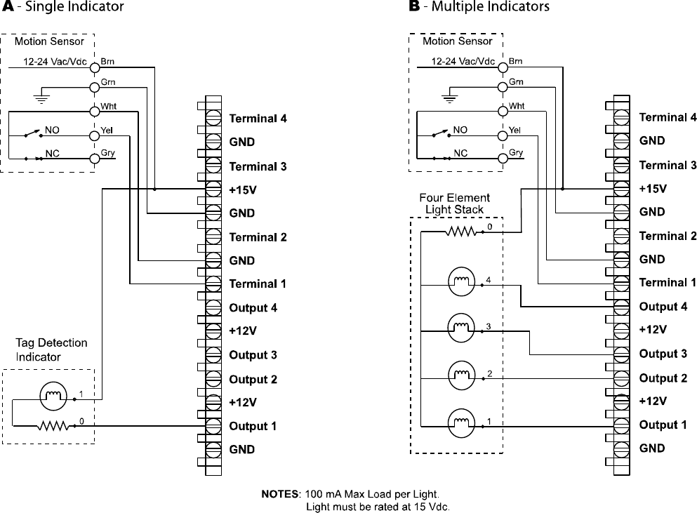
Appendix A Digital I/O Interface Module
90 3M Compact RFID Reader 1000 User’s Guide
In addition to input switches, indicators such as an LED light stack can be
connected to the outputs. If using a single element light stack, connect the
device as shown in the following figure (A).
If using a multiple element light stack, such as the Allen Bradley 855T,
connect the device as shown in the following figure (B).
In the following example, the four-element light stack (Allen Bradley 855T)
must be installed with the common (0) connected to +15V and each
element (1, 2, 3, 4) connected to the appropriate output. This allows the
reader to pull the LED low.
If you are installing individual indicators or lights, connect each indicator as
shown in the following figure (A). The maximum load per light can not
exceed 100 mA.

Appendix B USB Port Setup
3M Compact RFID Reader 1000 User’s Guide 91
B USB Port Setup
The 1000 is equipped with two USB 2.0 ports:
USB Type B – Provides connectivity to the 1000 console. This
connection is used to send commands and receive responses and is
typically connected to your server.
USB Type A – Used for external devices such as printers, external hard
drives, or other peripherals.
For standard communications, connect a USB Type B cable to the reader
and then to your PC or server. The maximum cable length is five meters to
the nearest hub, router, or computer.
B.1. Windows XP Driver Installation and Setup
1 Create a directory called:
c:\Windows\System32\drivers\3M
2 Copy file linux-cdc-acm.inf from the USBWinDrivers directory
on your Documentation CD into the new directory.
3 Verify that the c:\Windows\System32\drivers\usbser.sys
exists.
4 If the file exisits, go to Step 7.
5 If the file does not exist does not, copy file xp_usbser.sys from the
USBWinDrivers directory on your Documentation CD into
c:\Windows\System32\drivers.
6 After copying, rename xp_usbser.sys to usbser.sys .
7 Connect the reader to your computer using an A-B USB cable.
8 After a brief delay, your computer will detect a new device and the
Hardware Wizard will pop up.
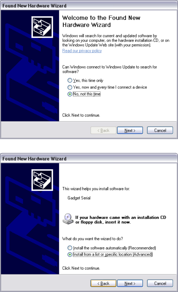
Appendix B 1000 DIO Interface Module
92 3M Compact RFID Reader 1000 User’s Guide
9 Select No, not this time and click Next.
10 Select Install from a list or specific location (Advanced) and click
Next.
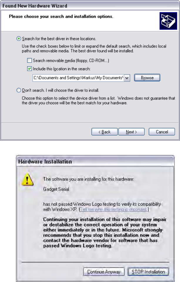
Appendix B USB Port Setup
3M Compact RFID Reader 1000 User’s Guide 93
11 Setup the path to the driver and click Next.
12 Since the Gadget Serial driver has not passed the Windows Logo testing,
a warning appears. Press Continue Anyway.
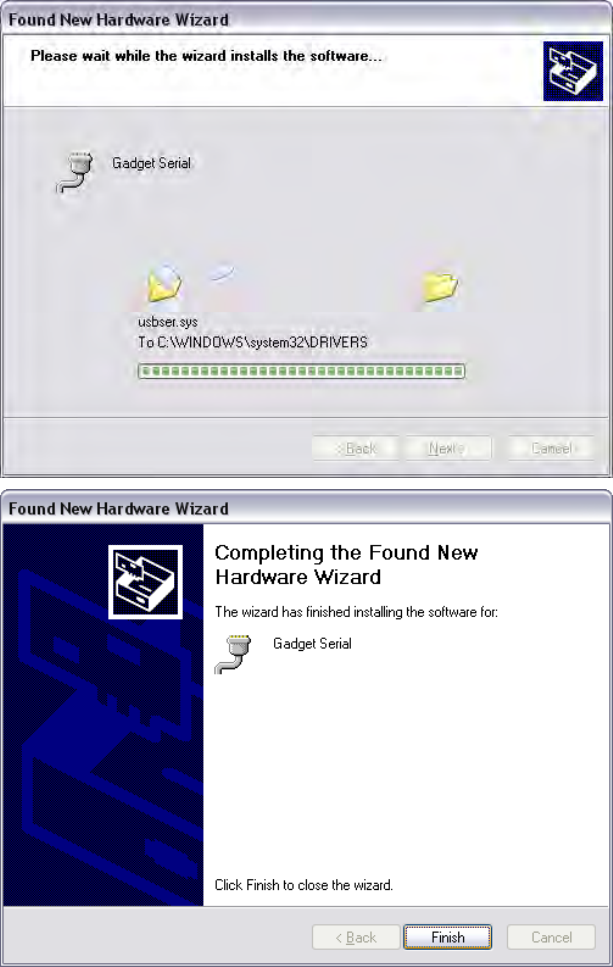
Appendix B 1000 DIO Interface Module
94 3M Compact RFID Reader 1000 User’s Guide
13 Once the installation is complete, press Finish.
14 Open the Device Manager and verify the driver was installed correctly as
shown in the following:
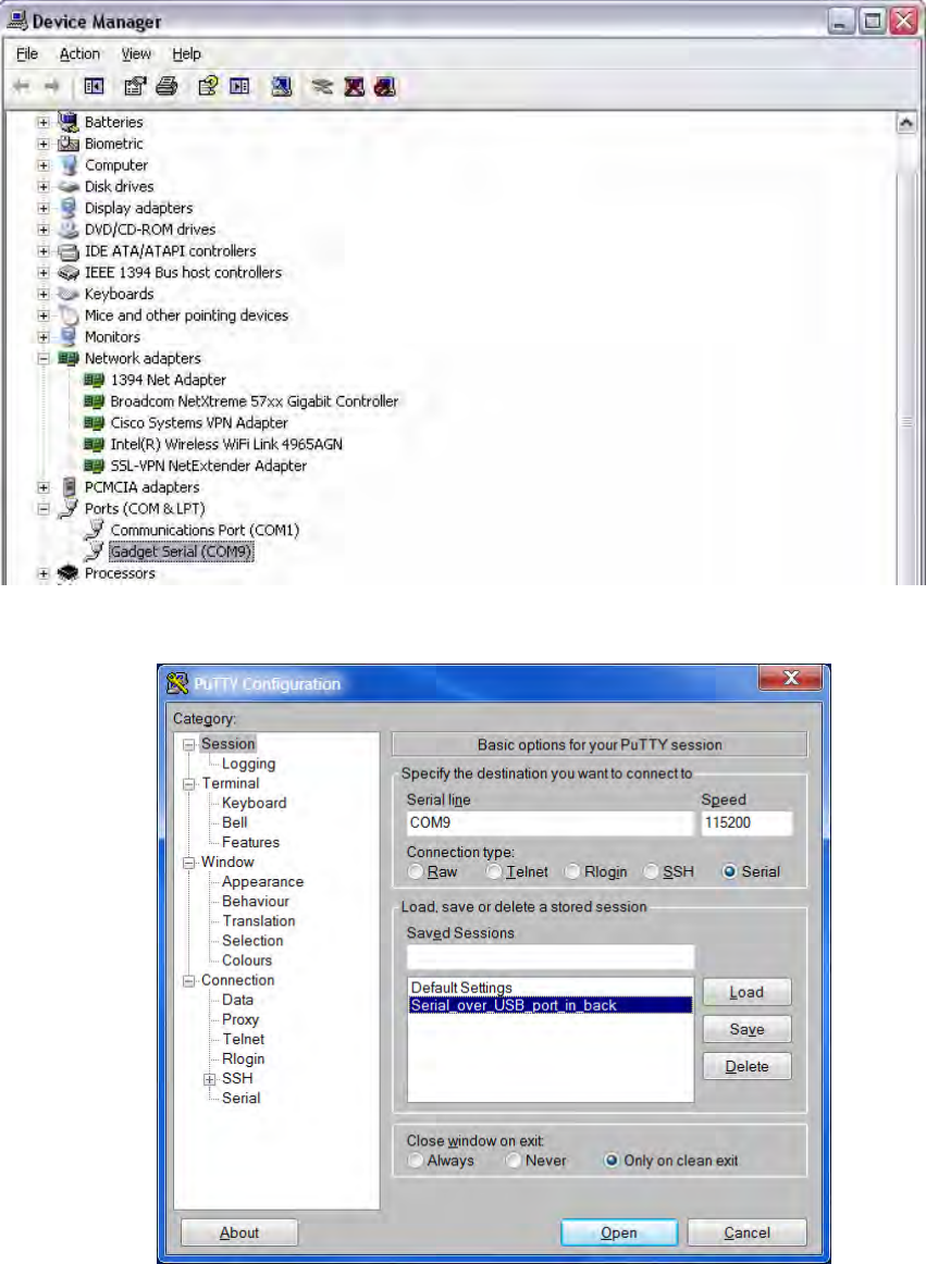
Appendix B USB Port Setup
3M Compact RFID Reader 1000 User’s Guide 95
15 After driver installation, start PuTTY and configure the new COM port as
follows:
16 In the left pane, select Serial under Connection.
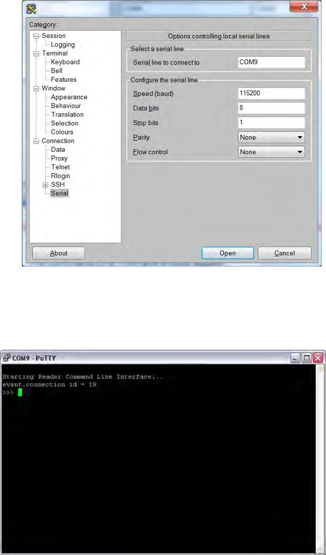
Appendix B 1000 DIO Interface Module
96 3M Compact RFID Reader 1000 User’s Guide
17 Enter the new COM port for USB serial and baud, data bits, stop bits,
parity and flow control.
18 Click the Open button.
19 The Command Line Interface should appear. If not, press Enter key
couple times.
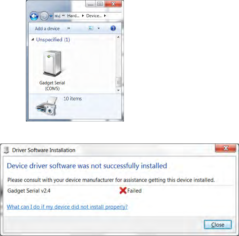
Appendix B USB Port Setup
3M Compact RFID Reader 1000 User’s Guide 97
B.2. Windows 7 Driver Installation and Setup
To map the Gadget Serial driver on a Windows 7 machine, perform the
following:
1 Connect the reader to your computer using an A-B USB cable.
2 If the Gadget Serial driver is already mapped to a COM port, the
following will appear:
3 If the driver is not mapped, the Driver Software Installation warning will
appear.
4 Select Control Panel and click View Devices and Printers. The Gadget
Serial device should not be mapped to any COM port as follows:
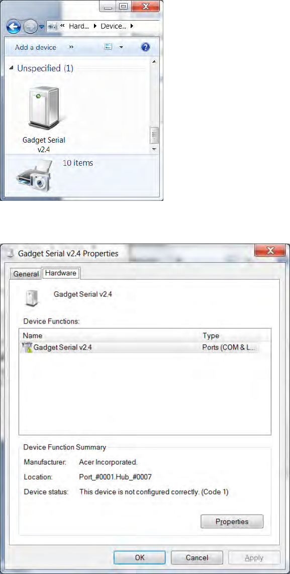
Appendix B 1000 DIO Interface Module
98 3M Compact RFID Reader 1000 User’s Guide
5 Right click the device and click Properties.
6 Select the Hardware tab.
7 Click the Properties button.
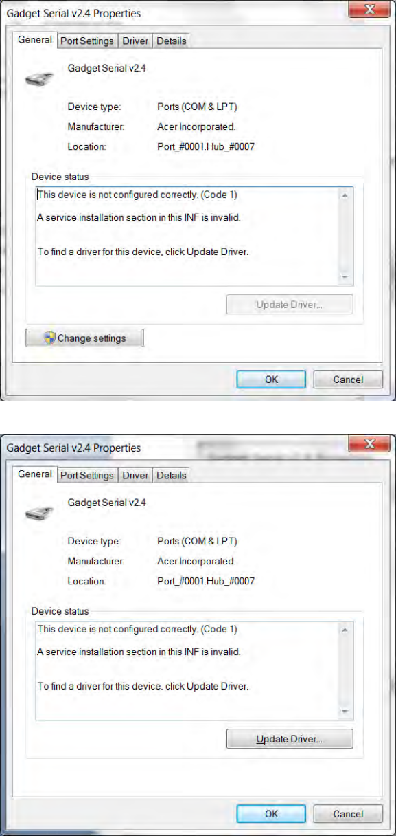
Appendix B USB Port Setup
3M Compact RFID Reader 1000 User’s Guide 99
8 Click the Change Settings button.
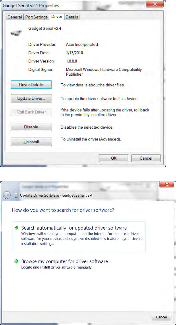
Appendix B 1000 DIO Interface Module
100 3M Compact RFID Reader 1000 User’s Guide
9 Click the Driver tab.
10 Click the Update Driver button.
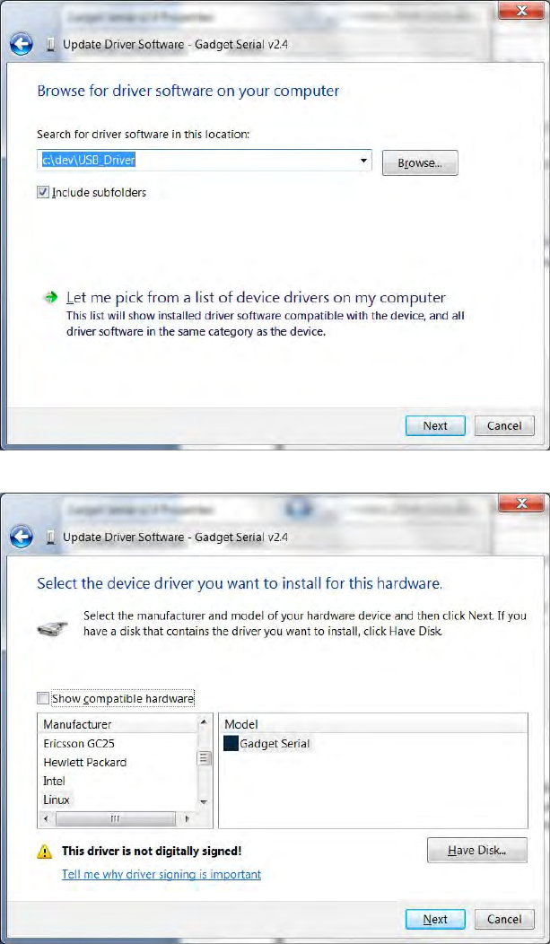
Appendix B USB Port Setup
3M Compact RFID Reader 1000 User’s Guide 101
11 Select Browse my computer for driver software.
12 Select Let me pick from list of device drivers on my computer.
13 Uncheck the Show compatible hardware checkbox.
14 Click the Gadget Serial and click the Have Disk… button.
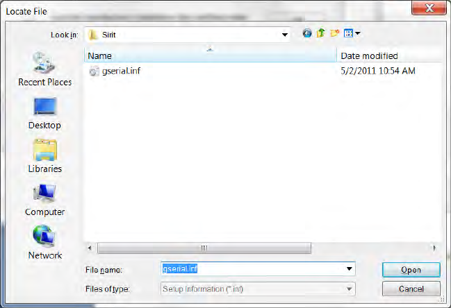
Appendix B 1000 DIO Interface Module
102 3M Compact RFID Reader 1000 User’s Guide
15 Create a directory called:
c:\windows\system32\drivers\3M
16 Find out whether the Window 7 is 32 bit or 64 bit. Go to Control Panel-
>System and Security->System and check “System type”, it will show
32-bit Operating System or 64-bit Operating System.
17 If your Windows 7 system is 32 bit, (for 64 bit system skip this step and
go to next step) copy the files gserial.inf and
win7_32bit_usbser.sys from the USBWinDrivers directory on
your Documentation CD into the new directory. After copying files,
rename win7_32bit_usbser.sys to usbser.sys.
18 If your Windows 7 system is 64 bit, (for 32 bit system, skip this step)
copy files linux-cdc-acm.inf and win7_64bit_usbser.sys from the
USBWinDrivers directory on your Documentation CD into the new
directory. After copying files, rename win7_32bit_usbser.sys to
usbser.sys.
19 Check if the c:\Windows\System32\drivers\usbser.sys
exists. If not, copy usbser.sys from:
c:\windows\system32\drivers\3M
to:
c:\windows\system32\drivers.
20 Go to c:\windows\system32\drivers\3M.
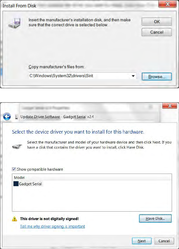
Appendix B USB Port Setup
3M Compact RFID Reader 1000 User’s Guide 103
21 For Windows 32 bit system, click the file gserial.inf, for Windows
64 bit system click the file linux-cdc-acm.inf. Then, click Open.
22 Click OK.
23 Click Next.
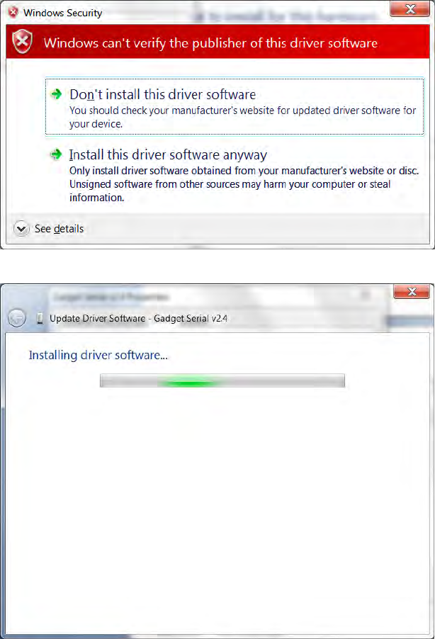
Appendix B 1000 DIO Interface Module
104 3M Compact RFID Reader 1000 User’s Guide
24 Select Install this driver software anyway.
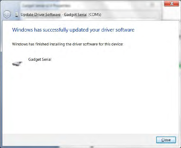
Appendix B USB Port Setup
3M Compact RFID Reader 1000 User’s Guide 105
25 Press Close.
26 The driver is now mapped to COM5 and is ready for use.
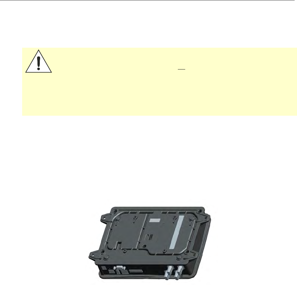
Appendix C Disposal of the 3M Compact RFID Reader 1000
106 3M Compact RFID Reader 1000 User’s Guide
C Disposal of the 3M Compact RFID Reader 1000
Prior to disposing of the 3M Compact RFID Reader 1000, the battery must
be removed. The battery used in the 1000 is a Lithium/Manganese Dioxide
(Li/MnO2) type. This battery contains no measurable amounts of mercury,
lead, or cadmium.
Caution: The procedure outlined in this appendix requires opening the 3M Compact
RFID Reader 1000 case in order to remove the battery prior to disposal.
Opening the case of the 1000 will void the warranty. In addition, opening the
case may adversely affect future performance of the reader.
Never open the case of the 1000 unless you are going to remove the battery
and dispose of the unit.
All disposal operations must be performed within local guidelines and laws. It
is the responsibility of the reader owner to ensure all local and regional laws
and regulations are followed for proper reader disposal.
To remove the battery, perform the following:
1 Remove the reader from service and disconnect any power, antenna,
and communication cables.
2 Place the reader on a static protected surface.
3 Turn the reader so the bottom of the reader is facing up as shown in the
following figure.
4 Using a Torx screwdriver, remove the six (6) Torx screws securing the
reader base to the reader enclosure.
5 Lift the base off the enclosure.
6 Remove the retaining nuts on each antenna connector
7 Remove the two (2) retaining nut/screws on each side of the serial
connector.
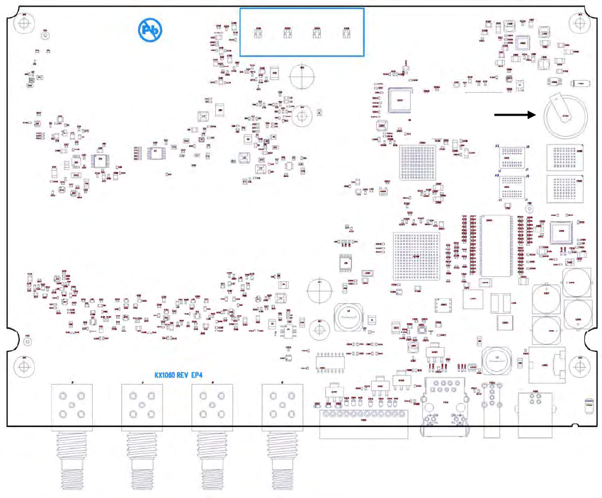
Appendix B Disposal of the 3M Compact RFID Reader 1000
3M Compact RFID Reader 1000 User’s Guide 107
8 Lift out the main circuit board and turn over.
9 Locate the battery on the upper right quadrant of the board.
10 Use a small flat-blade screwdriver to push the battery out of the holder.
11 Properly dispose of battery according to local and regional laws and
regulations.
12 Replace the main circuit board and install the base on the reader.
13 Using a Torx (T15) screwdriver, Install the six (6) torx screws to secure
the reader base to the reader enclosure.
14 Properly dispose of reader according to local and regional laws and
regulations.
Battery
3M Compact RFID Reader
1000
User’s Guide
This page intentionally left blank.

3M Compact RFID Reader 1000
User’s Guide