ACOEM EGL1101 GATEWAY FOR RADIO FREQUENCY SENSOR User Manual Eagle
ACOEM GATEWAY FOR RADIO FREQUENCY SENSOR Eagle
ACOEM >
Contents
- 1. User manual 1 - 2AC3Z-EGL1101.pdf
- 2. User manual 2 - 2AC3Z-EGL1101.pdf
- 3. User Manual Attestation statement - 2AC3Z-EGL1101.pdf
User manual 2 - 2AC3Z-EGL1101.pdf


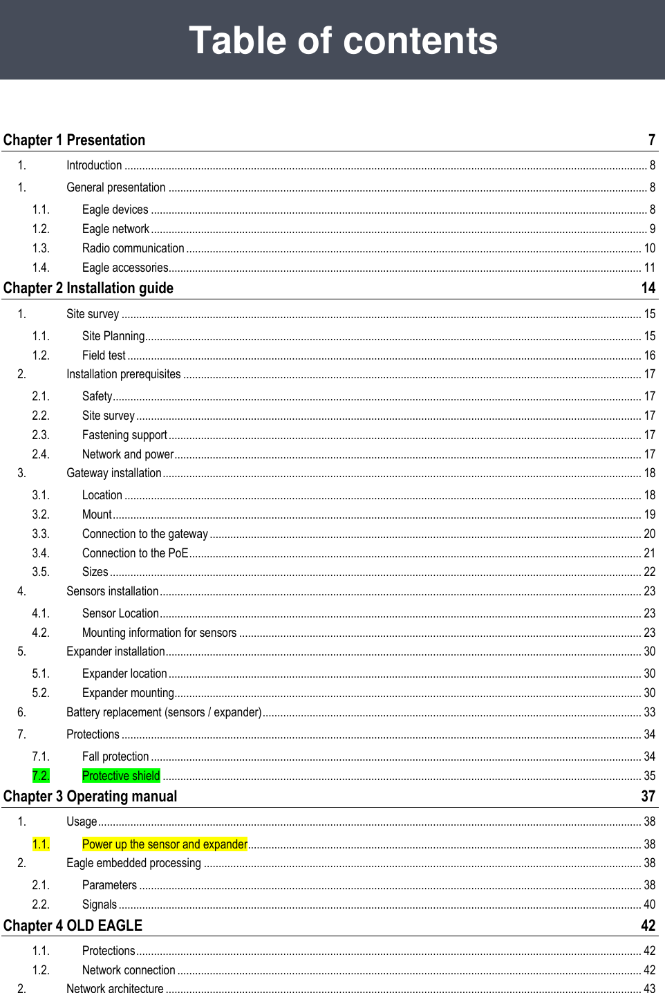


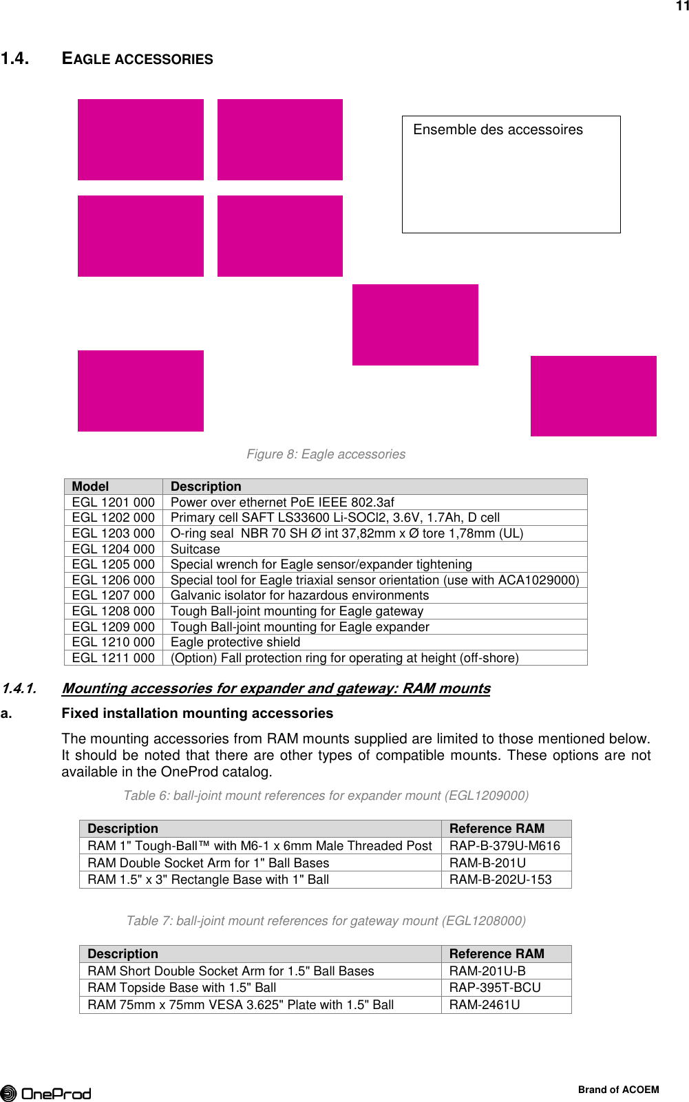
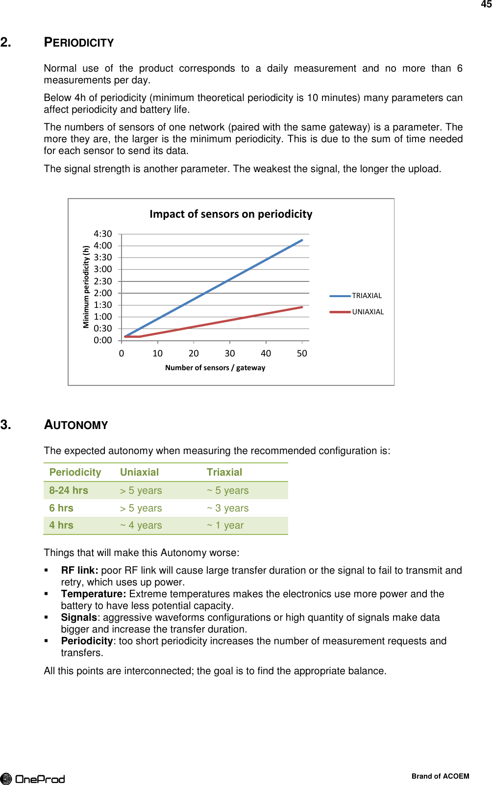
![12 Brand of ACOEM Figure 9: EGL1208000 ball-joint mount for gateway Figure 10: EGL1209000 ball-joint mount for expander b. Starter kit mounting accessories The starter kit comes with tough-claw instead of Vesa plate or rectangle base The RAM Tough-Claw™ is the perfect mounting base for quick and easy tool-less installation and removal on round, square, odd shaped rails and bars. The Tough-Claw™ can be clamped on rails from 25.4 mm to 57.15 mm [1" to 2.25"] outer diameter. Rubber pads provide stable, even gripping and protection of mounting surface. Clamp jaw is configured for round, flat and odd shapes. Clamping Range (Rail/Tube Surfaces): 25.4 mm to 57.15 mm [1" to 2.25"] Clamping Range (Flat Surfaces): 0 to 55 mm [0" to 2.2"] Physical Dimensions: Height: 167 mm [6.56"], Width: 57.15 mm [2.25"] Material: High strength glass filled nylon construction with corrosion resistant stainless steel hardware Description Reference RAM RAM LARGE TOUGH-CLAW 1.5" DIAMETER BALL RAP-401U RAM LARGE TOUGH-CLAW 1" DIAMETER BALL RAP-B-401U Figure 11: RAM Tough-Claw™](https://usermanual.wiki/ACOEM/EGL1101.User-manual-2-2AC3Z-EGL1101-pdf/User-Guide-2553674-Page-12.png)


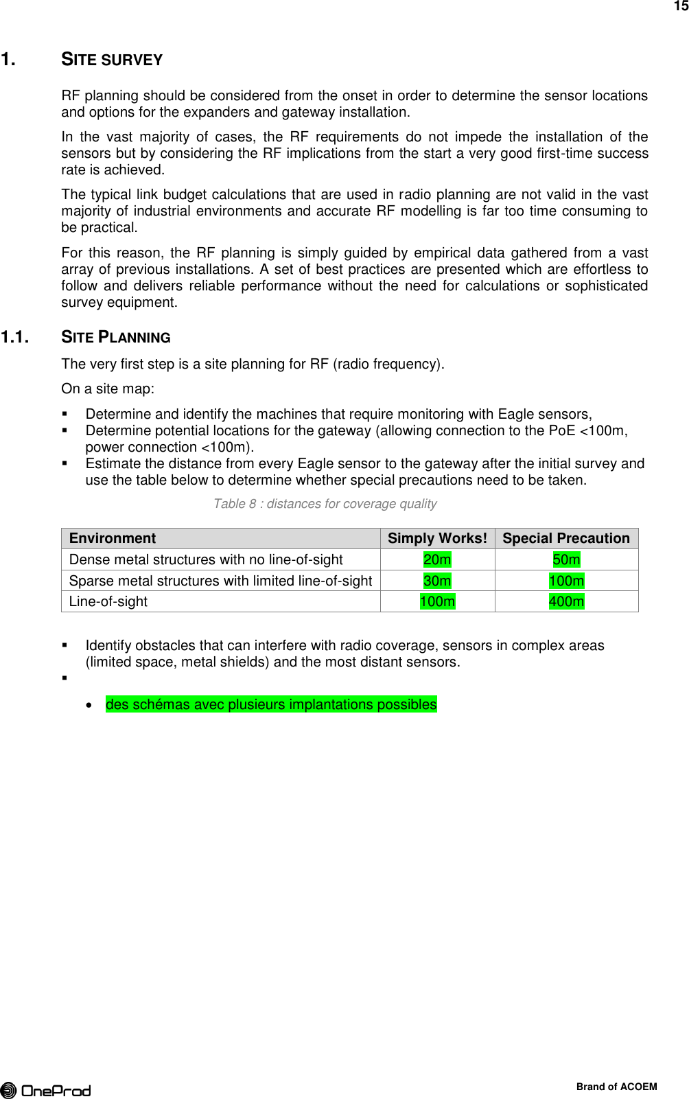
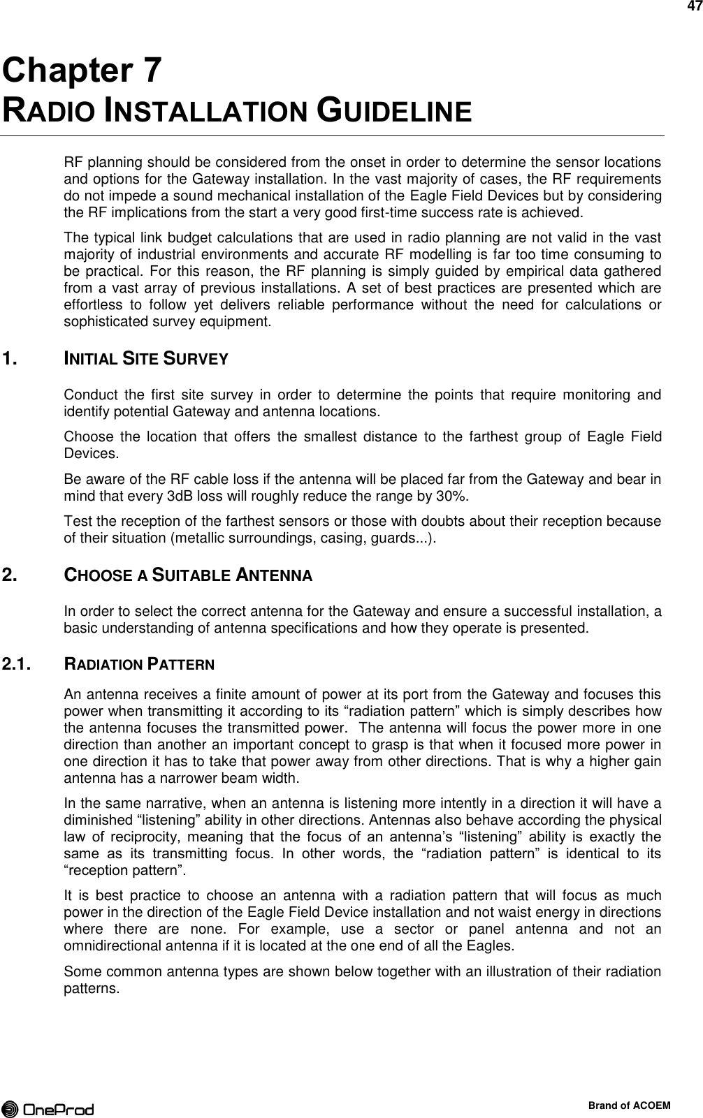
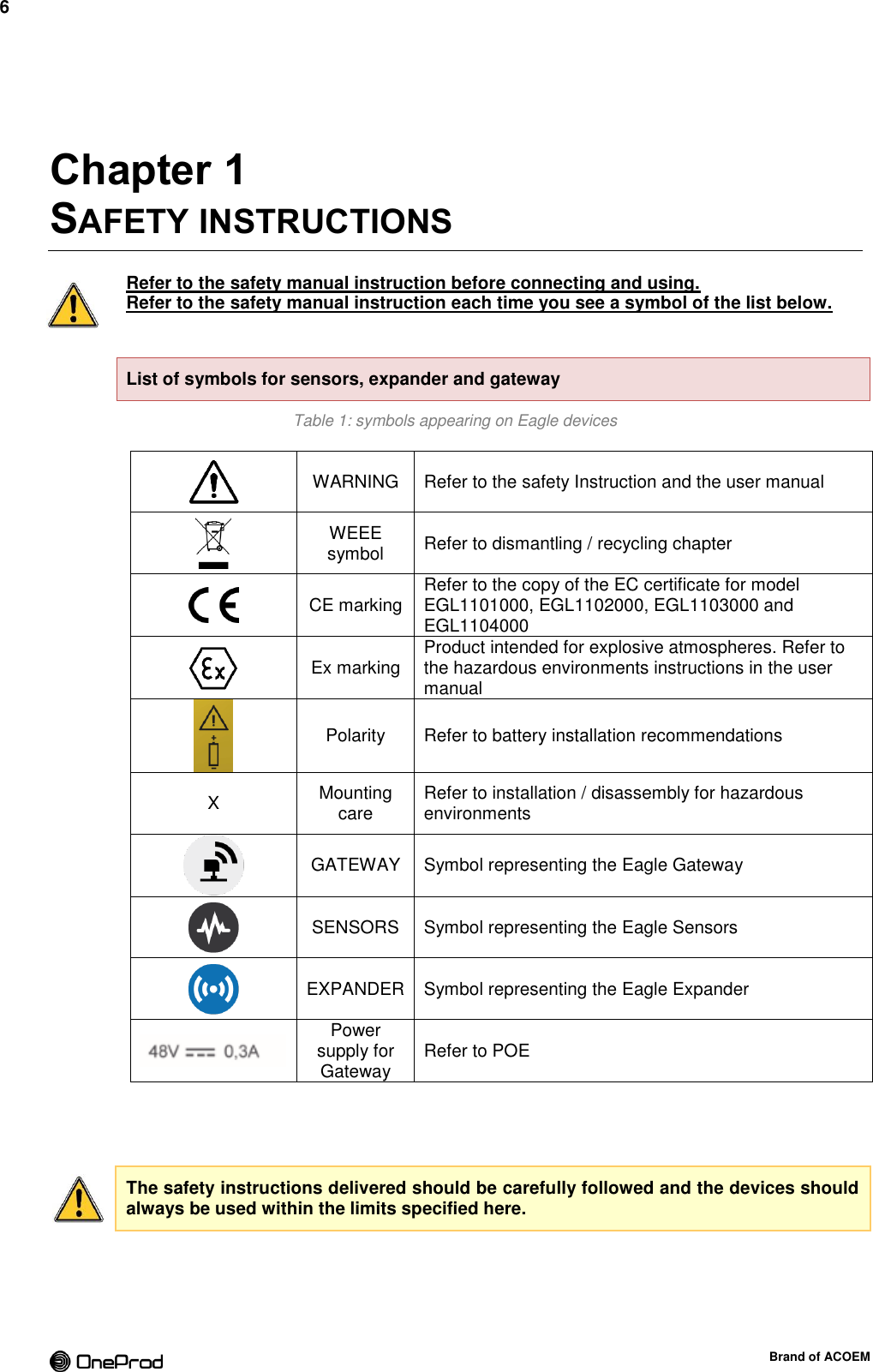
![17 Brand of ACOEM 2. INSTALLATION PREREQUISITES 2.1. SAFETY Refer to safety instructions, safety standards and procedures before installing any device. 2.2. SITE SURVEY At this step the site survey is done. The location of the gateway, sensors and expanders are identified in a site plan and ensure to each sensor the appropriate radio coverage. 2.3. FASTENING SUPPORT The gateway must be placed on a wall or a pole at a height of about 5m [16 ft]. Adequate mounting support has to be installed on site (such as mast) if necessary and can therefore require the use of support facilities and operations of specific civil engineering if needed for the configuration of the area. 2.4. NETWORK AND POWER The gateway has to be powered and connected to the customer IP network Prior to installation, the site must be equipped with both power and ethernet connections. A technical cabinet can be necessary. The link to the customer IP network can be fiber-optic, copper…](https://usermanual.wiki/ACOEM/EGL1101.User-manual-2-2AC3Z-EGL1101-pdf/User-Guide-2553674-Page-17.png)
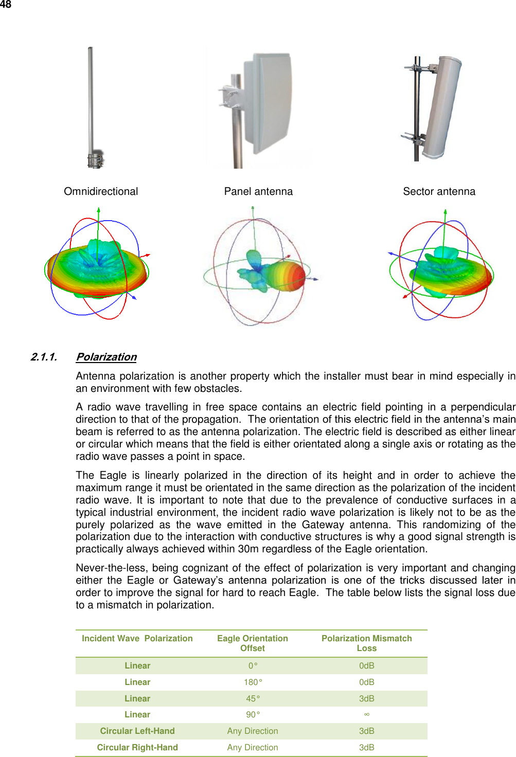
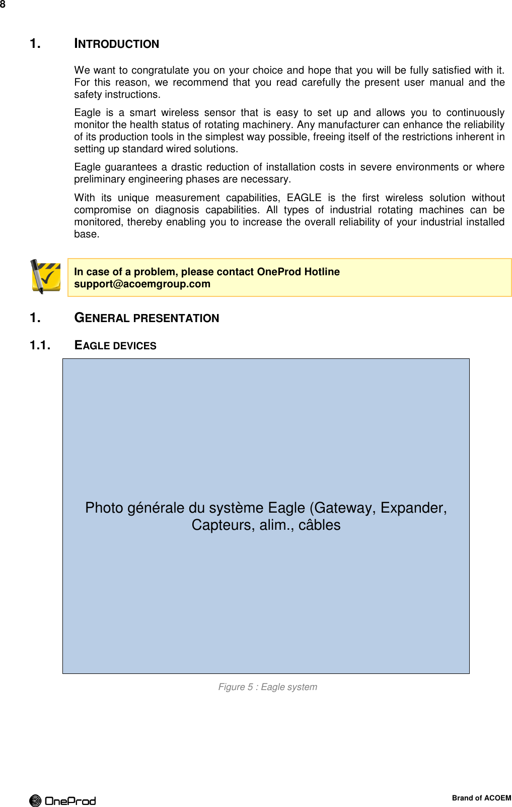
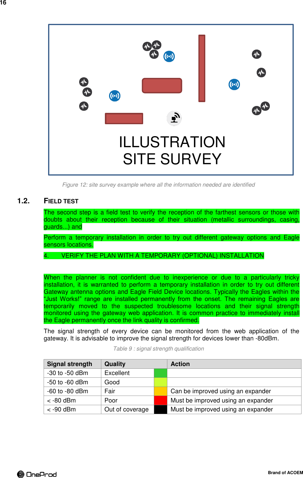
![18 Brand of ACOEM 3. GATEWAY INSTALLATION The gateway is fully assembled and ready to be deployed upon delivery. Only one gateway is necessary to ensure the operation of the whole multi-hop wireless infrastructure. Additional gateway may be necessary depending on The gateway is linking the wireless network of Eagle devices (ISA100.11a) to an IP network where the data are processed. In hazardous environments, the operator has to arrange organizational safety measures which reliably prevent the occurrence of an ignitable atmosphere, by default reduce the probability that a flammable atmosphere can occur at all (employing the use of suitable gas detection systems). 3.1. LOCATION The location of the gateway is very important. It must be placed at a height of about 5m [16 ft]. It must comply with a maximum radius of 100m [328 ft] radio coverage. The housing face with OneProd logo indicates the embedded antenna location. This face must be oriented in the direction of the sensors and expanders. The radio link is sensible to physical obstacles, such as vehicles, tanks, or walls. If the distance between the gateway and sensors or expanders exceed 100m [328 ft], it may be necessary to add an additional expander to improve the signal strength. Figure 13 : Eagle system overview GATEWAY 100 m 50 m EXPANDER SENSORS 5 m 1 to 5 m](https://usermanual.wiki/ACOEM/EGL1101.User-manual-2-2AC3Z-EGL1101-pdf/User-Guide-2553674-Page-18.png)
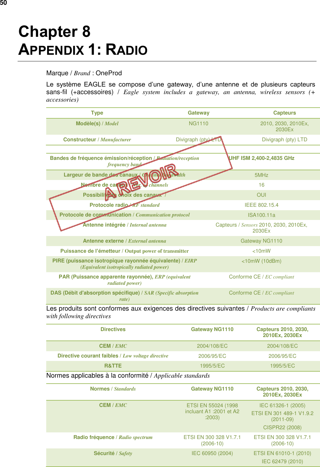
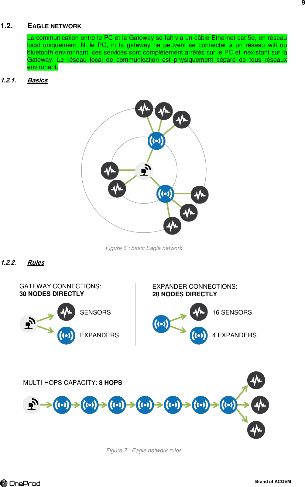
![23 Brand of ACOEM 4. SENSORS INSTALLATION 4.1. SENSOR LOCATION The sensors are mounted on the equipment to monitor following the rules for vibration sensor installation. Leave enough space around the sensor to ensure the best transmission/reception possible of radio signals. At least 100 mm around the device antenna (plastic cap). If the sensor has to be installed in tiny spaces, the use of an expander might be a solution to improve the radio coverage (if necessary). Figure 23 : clear space around the sensor/expander 4.2. MOUNTING INFORMATION FOR SENSORS A damp cloth should be used when installing or taking off the gateway in hazardous areas to eliminate static electricity resulting from this operation. Table 10 : mounting characteristics for sensors Thread M6-1, max depth 6mm [0.23 in] Flat mounting surface Ø32.5 mm x 1mm height [Ø1.28 in x 0.039 in] Hex head 44 mm [1.73 in] Fastening torque 5 – 7 Nm [44 – 62 inch-lb] CAUTION: Do not grasp the sensor by the plastic cap. Do not hit the plastic cap. Do not tighten the sensor by the plastic cap 5 mounting modes: Direct mounting: M6 stud on a flat surface Spotface mounting : for convex surface Cementing pad: the easiest way to install Triaxial mount: to position the triaxial sensor accurately. Temporary mount: only for testing wireless coverage before final assembly. Ø100 mm clear space](https://usermanual.wiki/ACOEM/EGL1101.User-manual-2-2AC3Z-EGL1101-pdf/User-Guide-2553674-Page-23.png)
![24 Brand of ACOEM Figure 24: sensor and expander mounting interface (threads, hex head) Flat mounting surface Ø32.5 mm x 1mm height [Ø1.28 in x 0.039 in] M6-1, 6 mm [M6-1, 0.23 in] AMELIORER DESSIN Hex head 44 mm [1.73 in]](https://usermanual.wiki/ACOEM/EGL1101.User-manual-2-2AC3Z-EGL1101-pdf/User-Guide-2553674-Page-24.png)
![25 Brand of ACOEM 4.2.1. Direct mounting See Figure 25 Ensure a flat surface: remove paint layers. Step 1. NOTE: if you use a spot facing tool be sure to not exceed 0.8mm depth [0.031 in]. Drill a hole (Ø5 mm and XXmm depth [Ø 0.19 in - ) Step 2. Thread the hole with M6 tap Step 3. Screw M6 stud with a length of XXmm Step 4. CAUTION: The part of the stud inserted into the sensor can be up to 6 mm [0.23 in]. A bottoming stud may cause base-strain and also potentially damage electronics. Screw the sensor on the stud and tighten at 5 - 7 Nm [44 - 62 inch-lb] using the Step 5. dedicated tube wrench and your handgrip. NOTE: for a better contact a film of grease/oil can be applied between sensor and mounting surface (note the oil/grease must be compatible with the temperature of the measurement point). CAUTION: If you use a 44mm wrench [1.73 in] or an adjustable wrench be careful to observe the indicated torque range. Fill in the installation report with sensor information (S/N, type, location, Step 6. orientation…) Figure 25: direct mounting with M6 stud Figure 26: spotface mounting](https://usermanual.wiki/ACOEM/EGL1101.User-manual-2-2AC3Z-EGL1101-pdf/User-Guide-2553674-Page-25.png)
![26 Brand of ACOEM 4.2.2. Spotface mounting See Figure 26 This mounting mode is mainly dedicated to convex surfaces or to remove paint layers on a machine. Picture Reference Description ACA1030000 Washer adapter for 1"1/4 spotface + M6 stud Create a flat surface on the machine using a 1.25” [31.75 mm] spot facing tool with Step 1. a drill bit for an M6 tap Do not exceed 2 mm depth. Thread the hole with M6 tap Step 2. Screw M6 stud with a length of XXmm Step 3. CAUTION: The part of the stud inserted into the sensor can be up to 6 mm. A bottoming stud may cause base-strain and also potentially damage electronics. Thread the washer adapter on the stud. This washer is necessary to adapt the Step 4. 1.25” spotface depth and diameter to the sensor design. Screw the sensor on the stud and tighten at 5 - 7 Nm [44 - 62 inch-lb] using the Step 5. dedicated tube wrench and your handgrip. NOTE: for a better contact a film of grease/oil can be applied between sensor and mounting surface (note the oil/grease must be compatible with the temperature of the measurement point). CAUTION: If you use a 44 wrench or an adjustable wrench be careful to observe the indicated torque range. Fill in the installation report with sensor information (S/N, type, location, Step 6. orientation…) Figure 27: spotfacing tool with drill bit TRADUIRE COIMPLETER](https://usermanual.wiki/ACOEM/EGL1101.User-manual-2-2AC3Z-EGL1101-pdf/User-Guide-2553674-Page-26.png)
![27 Brand of ACOEM 4.2.3. Cementing pad mounting This mounting mode is fast and easy. Picture Reference Description ACA1023000 M6 cementing pad - Ø35 mm [1.38 in] Recommended adhesives: HBM® X60: is a 2-component fast curing adhesive, consisting of a liquid component and a powder. LOCTITE® F246™: is a one component, toughened and high strength acrylic adhesive system for structural bonding. Remove coats of paint to get a clean metallic surface on the machine Step 1. Remove grease from the surface Step 2. Glue the cementing pad using HBM® X60 or LOCTITE® F246™ adhesive. Pin the Step 3. pad to the surface. WARNING: Refer to gluing safety datasheet and procedures before gluing and always wear the prescribed protections. Wait for the glue to dry Step 4. Screw the sensor on the cementing pad and tighten at 5 - 7 Nm [44 - 62 inch-lb] Step 5. using the dedicated tube wrench and your handgrip. NOTE: for a better contact a film of grease/oil can be applied between sensor and cementing pad (note the oil/grease must be compatible with the temperature of the measurement point). CAUTION: If you use a 44 wrench or an adjustable wrench be careful to observe the indicated torque range. Fill in the installation report with sensor information (S/N, type, location, Step 6. orientation…) Figure 28 : cementing pad mounting](https://usermanual.wiki/ACOEM/EGL1101.User-manual-2-2AC3Z-EGL1101-pdf/User-Guide-2553674-Page-27.png)
![28 Brand of ACOEM 4.2.4. Triaxial mount This mounting mode is dedicated to triaxial sensors. It helps to Picture Reference Description ACA1029000 Specific fastening for triaxial sensors (washer and stud) Ensure a flat surface: remove paint layers. Step 1. NOTE: if you use a spot facing tool be sure to not exceed 2 mm depth [0.078 inch]. Step 2. Create a flat surface on the machine using a 1.25” spot facing tool with a drill bit for an M8 tap Do not exceed XX mm depth. Drill a hole (Ø6.8 mm and XXmm depth [Ø 0.28 in – XX in) Step 3. Thread the hole with M8 tap Step 4. Screw special M8 stud in the machine Step 5. Thread the washer on the stud. This washer is necessary to adapt the 1.25’’ Step 6. spotface depth and diameter to the sensor design. Screw the sensor on the M6 side of the stud until contact without tightening it. Step 7. Identify orientation of the triaxial sensor axis. Step 8. Turn the washer to adjust the axis orientation in the chosen direction Step 9. Use the dedicated tool for orientation if the dedicated tube wrench is also used. Screw the sensor on the stud and tighten at 5 - 7 Nm [44 - 62 inch-lb] using the Step 10. dedicated tube wrench and your handgrip. NOTE: for a better contact a film of grease/oil can be applied between mounting surfaces (note the oil/grease must be compatible with the temperature of the measurement point). CAUTION: If you use a 44 wrench or an adjustable wrench be careful to observe the indicated torque range. Fill in the installation report with sensor information (S/N, type, location, Step 11. orientation…) Figure 29 : specific fastening for triaxial sensors](https://usermanual.wiki/ACOEM/EGL1101.User-manual-2-2AC3Z-EGL1101-pdf/User-Guide-2553674-Page-28.png)
![29 Brand of ACOEM 4.2.5. Temporary mount Performing field test during a site survey may require a temporary mount. This allows testing locations and orientations of the farthest sensors or those with doubts about their reception because of their situation (metallic surroundings, casing, guards…) to get the best coverage possible. A magnetic mount is the best solution in that specific case. Screw the sensor on the magnetic base using appropriated stud or bolt (M6). Step 1. Place the system on the location to test Step 2.NOTE: An adapter stud may be required depending on the design of the magnetic base to allow M6 mount. Table 11: magnetic mounts references Brand Reference Adapter stud Pull strength Max temp. CTC MH114-3A + MH108-5B 1/4-28 to M6-1 23kg [50lbs] 80°C [176°F] OneProd ACA To be defined N/A 23kg [50lbs] 80°C [176°F] Figure 30 : multi-purpose magnetic base](https://usermanual.wiki/ACOEM/EGL1101.User-manual-2-2AC3Z-EGL1101-pdf/User-Guide-2553674-Page-29.png)
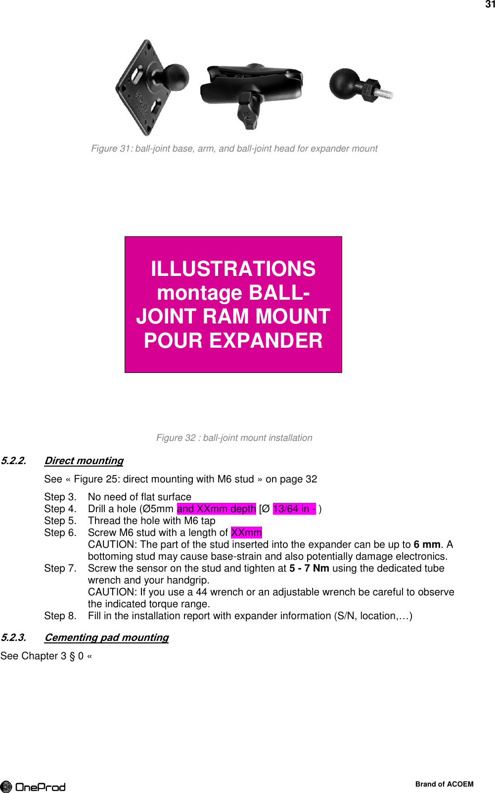
![30 Brand of ACOEM 5. EXPANDER INSTALLATION 5.1. EXPANDER LOCATION The location of the expanders is very important. It must comply with a maximum radius of 50m radio coverage. It must be located in the coverage of the gateway or of another expander. It is best practice to install the expanders at high to improve the coverage. This way the expander has a clear view of the sensors close to it. The blue plastic cap is where the embedded antenna is located. It must be oriented in the direction of the sensors or at least vertically. The radio link is sensible to physical obstacles, such as vehicles, tanks, or walls. If the distance between an expander and sensors exceed 50m or an obstacle is present, it may be necessary to add an additional expander to improve the signal strength. 5.2. EXPANDER MOUNTING A damp cloth should be used when installing or taking off the gateway in hazardous areas to eliminate static electricity resulting from this operation. Expander shares the same design as sensors. See “Figure 24: sensor and expander mounting interface (threads, hex head)” on page 31. Table 12: mounting characteristics for expander (identical to sensor) Thread M6-1, max depth 6mm [0.236 in] Flat mounting surface Ø32.5 mm x 1mm height [Ø1.28 in x 0.039 in] Hex head 44 mm [1.73 in] Fastening torque 5 - 7 Nm [44 - 62 inch-lb] CAUTION: Do not grasp the expander by the plastic cap. Do not hit the plastic cap. Do not tighten the expander by the plastic cap 4 mounting modes: Ball-joint mount : the most appropriate mounting allowing precise orientation Direct mounting: M6 stud on a flat surface Cementing pad: the easiest way to install Temporary mount: only for testing wireless coverage before final assembly. 5.2.1. Ball-joint mount The expander is fixed very quickly on a pole or on a wall using a ball-joint mount. The ball-joint mount is constituted of: A ball-joint head Screw the expander on M6-1 x 6MM male threaded post of the ball-joint head. A ball-joint base The base is to be pegged on a wall or on a pole. The mounting on a pole requires a clamp, nuts and washers. The mounting on a wall is done using four screws and anchors. The mounting on a structure requires bolts nuts and washers. An arm The arm is joining the two ball-joints allowing precise orientation of the expander.](https://usermanual.wiki/ACOEM/EGL1101.User-manual-2-2AC3Z-EGL1101-pdf/User-Guide-2553674-Page-30.png)
![32 Brand of ACOEM Cementing pad mounting » on page 34 5.2.4. Temporary mount A Tough-Claw™ is the perfect mounting base for quick and easy tool-less installation and removal on round, square, odd shaped rails and bars. The Tough-Claw™ can be clamped on rails from 25.4 mm to 57.15 mm [1" to 2.25"] outer diameter. See Chapter 2 § 1.4.1 b “Starter kit mounting accessories” on page 19. A magnetic base can also be used: See Chapter 3 § 4.2.5 « Temporary mount » on page 31](https://usermanual.wiki/ACOEM/EGL1101.User-manual-2-2AC3Z-EGL1101-pdf/User-Guide-2553674-Page-32.png)
![33 Brand of ACOEM 6. BATTERY REPLACEMENT (SENSORS / EXPANDER) Refer to Safety Instruction § 0 Standards applied: EN60079-0 edition 2012 Atmosphères explosives Partie 0 : Matériel - Exigences générales EN60079-11 edition 2012 Atmosphères explosives Partie 11: Protection de l’équipement par sécurité intrinsèque «i» IEC 60079-0 : 2011 Edition: 6.0 Explosive atmospheres - Part 0: General requirements IEC 60079-11 : 2011 Edition: 6.0 Explosive atmospheres - Part 11: Equipment protection by intrinsic safety "i" Special condition for a safe use: - -20°C ≤ Tamb ≤+85°C - WARNING – USE ONLY SAFT LS33600 BATTERY. Only replace the primary cell in a safe area - The equipment must be installed so that it is protected against mechanical shocks. - A damp cloth should be used when installing or taking off the sensors and expanders in all hazardous areas to eliminate static electricity resulting from this operation. Primary cell on page 9 before any battery replacement. Only use SAFT LS33600 3.6 V primary lithium-thionyl chloride (Li-SOCl2) D-size bobbin cell Use of any other battery causes risk of explosion Respect the orientation of the battery. A Mistake may result in short circuit of the cell. Step 1. Open the sensor by unscrewing the protection tube. If the tube is hard to unscrew, use a rubber strap wrench. Remove the old battery from the bottom side. Pull out the seals (pinch up it to grab it). Step 2. Prepare a new battery and 2 new seals. Use only primary cell SAFT LS33600 3.6 V lithium-thionyl chloride (Li-SOCl2) and O-ring seal NBR 70 SH Øint. 37.82mm [1 31/64 in] x Øtorus 1.78mm [1/16 in], UL MH25709 certified. Step 3. Use a cardboard (business card) to help the battery to slip in place and avoid short circuit. Step 4. Start to insert the battery from the bottom. The battery must be installed in the direction indicated by the polarity symbol. Step 5. Push the top part to fully insert the battery in its housing. Step 6. Place the new seals in the appropriate groove. Check that the battery is well inserted and manually close the sensor with the protection tube.](https://usermanual.wiki/ACOEM/EGL1101.User-manual-2-2AC3Z-EGL1101-pdf/User-Guide-2553674-Page-33.png)
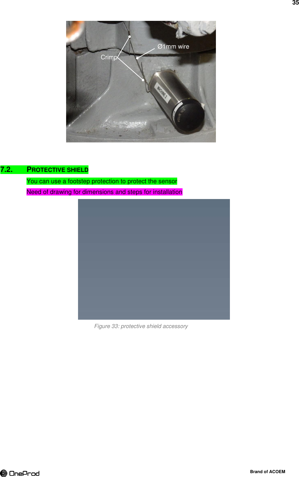
![34 Brand of ACOEM CAUTION: Only use your hands or a rubber strap wrench to remove the protection tube from the sensor/expander. The use of tongue-and-groove pliers (also known as water pump pliers, adjustable pliers, groove-joint pliers, arc-joint pliers, Multi-Grips, and Channellocks) are forbidden and will cause damages and lose of sealing IP67. 7. PROTECTIONS 7.1. FALL PROTECTION Make a sensor/expander tether with a stainless steel lanyard to provide more safety and avoid to the sensor/expander to fall. Step 1. Thread a thin cable through the Ø 2 mm hole [Ø 0.078 in] drilled into the sensor/expander. Thread the other side of the wire through a fixed object Step 2. Crimp the loop ends Step 3.1 2 3 6 4 5 CLIP](https://usermanual.wiki/ACOEM/EGL1101.User-manual-2-2AC3Z-EGL1101-pdf/User-Guide-2553674-Page-34.png)