ADC Telecommunications DAS8-4-W In-Building Distributed Antenna System User Manual J bonnie john front cover eps
ADC Telecommunications Inc. In-Building Distributed Antenna System J bonnie john front cover eps
Contents
- 1. Part 1 Users Manual
- 2. Part 2 Users Manual
- 3. Radiation Warning pages of user manual
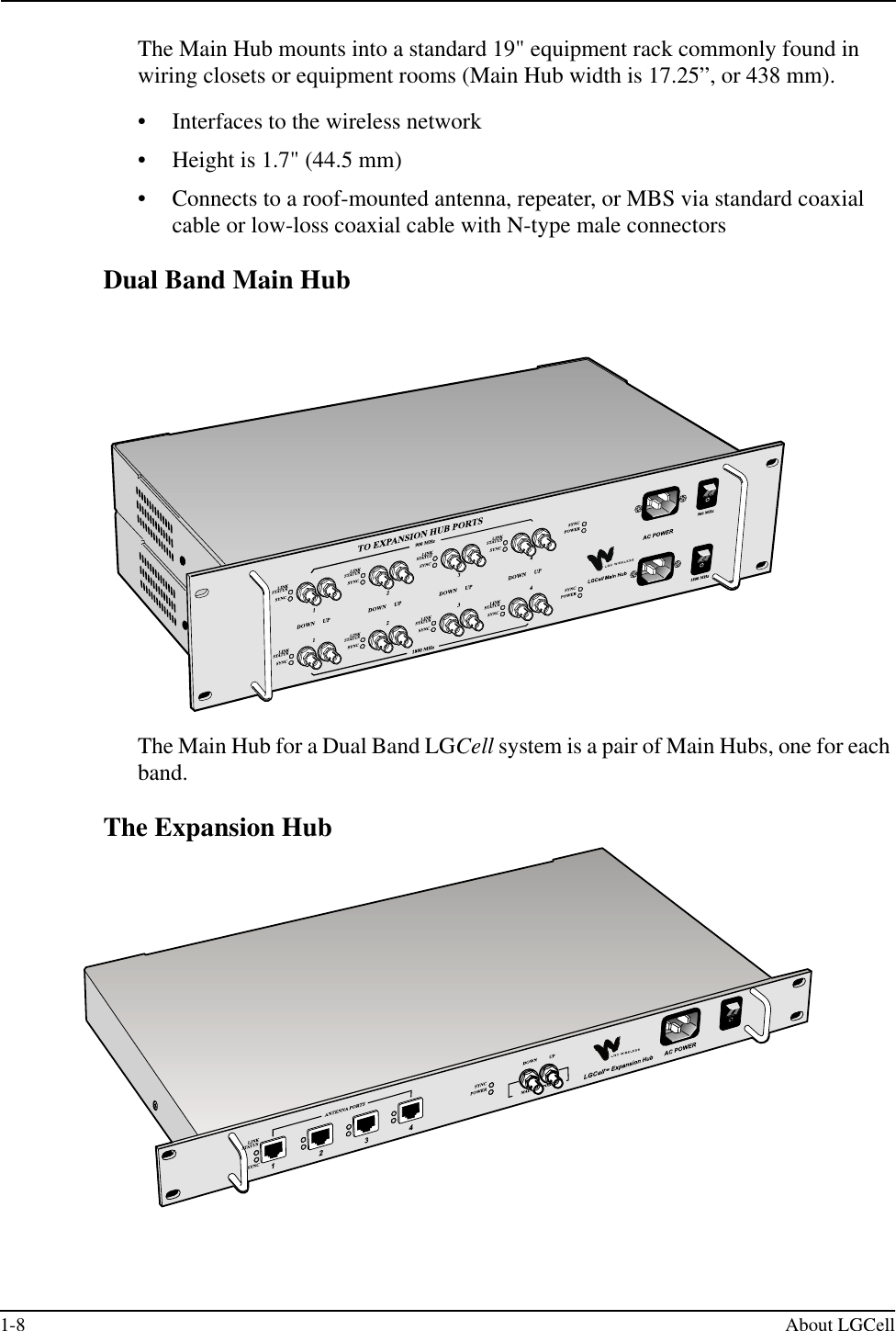
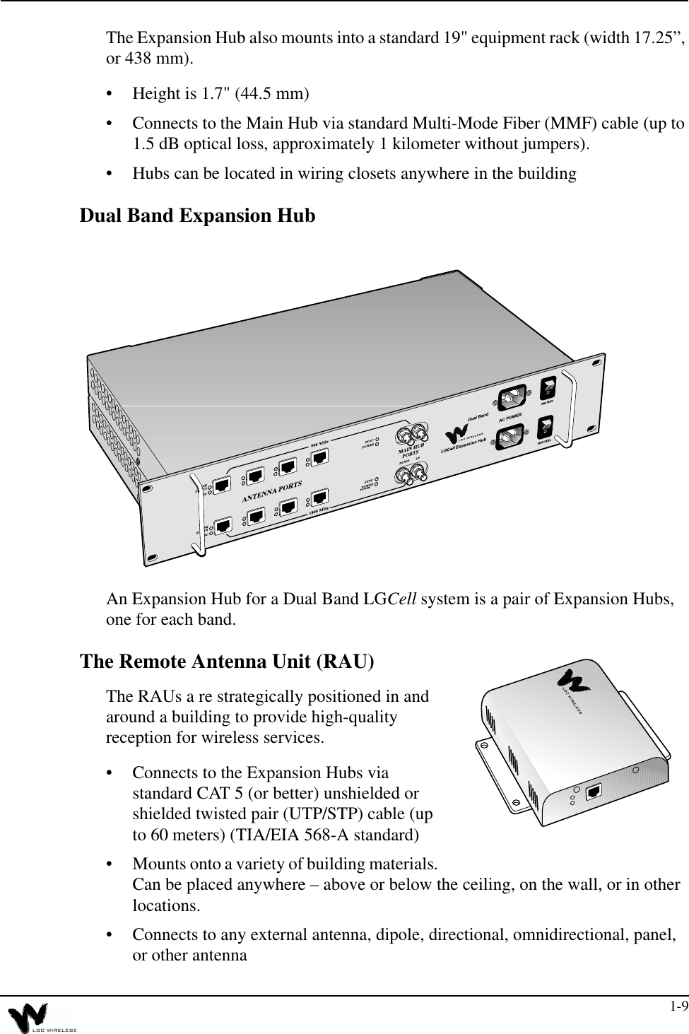
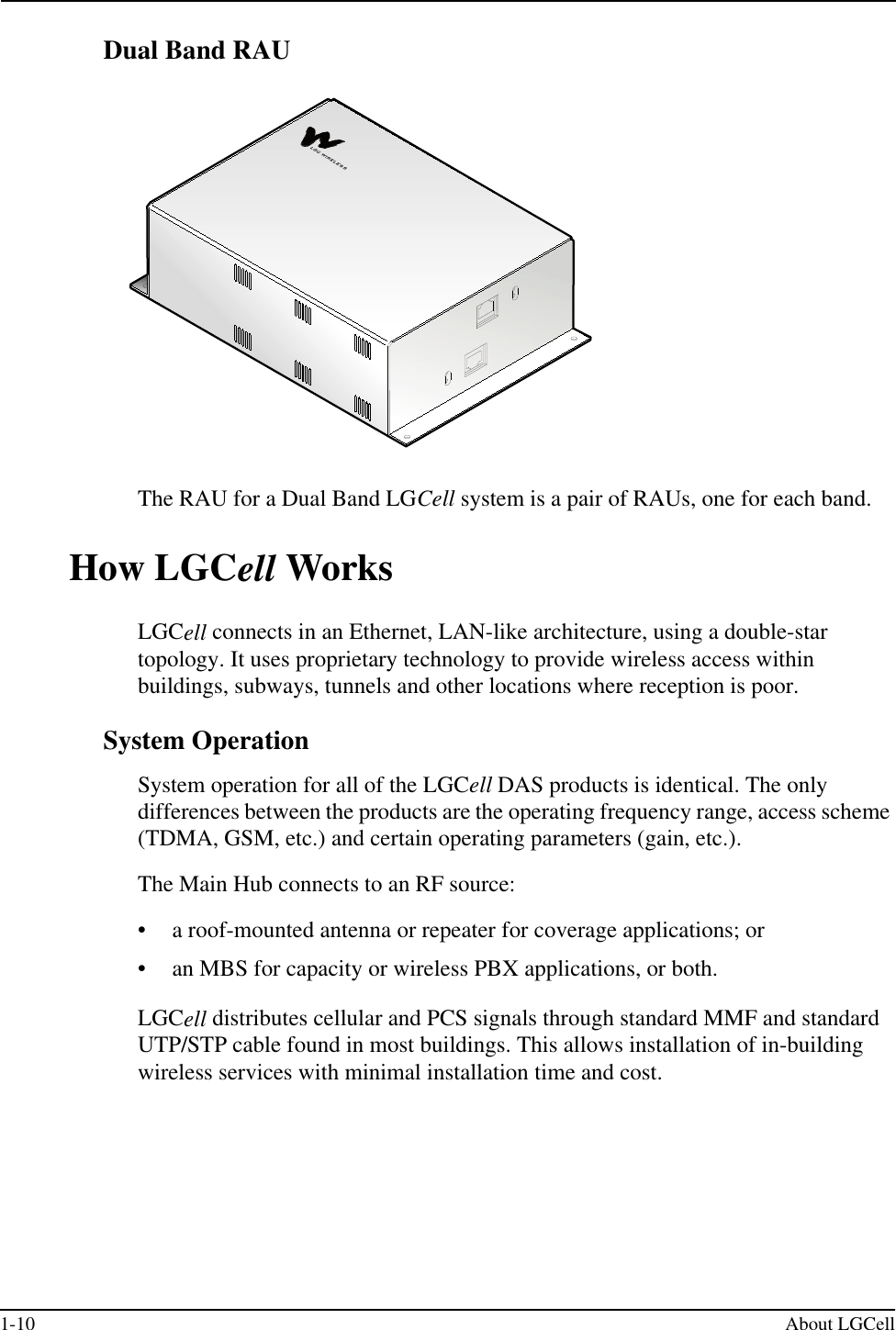
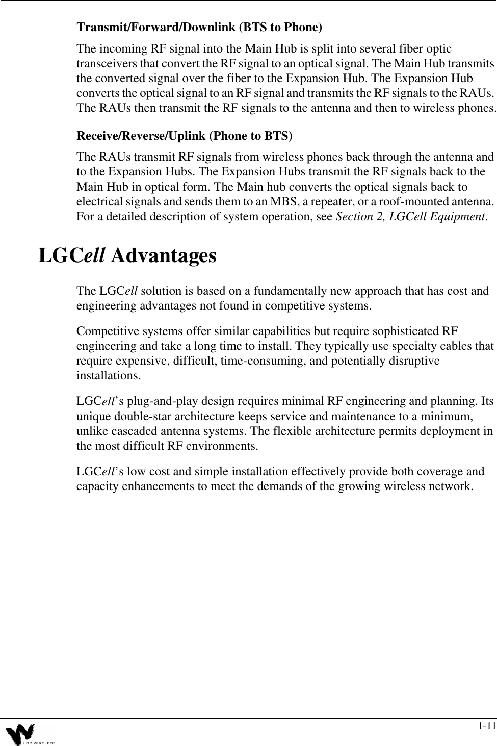
Part 1 Users Manual

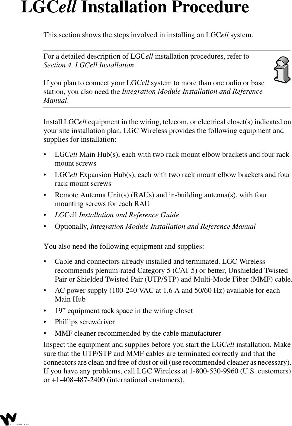
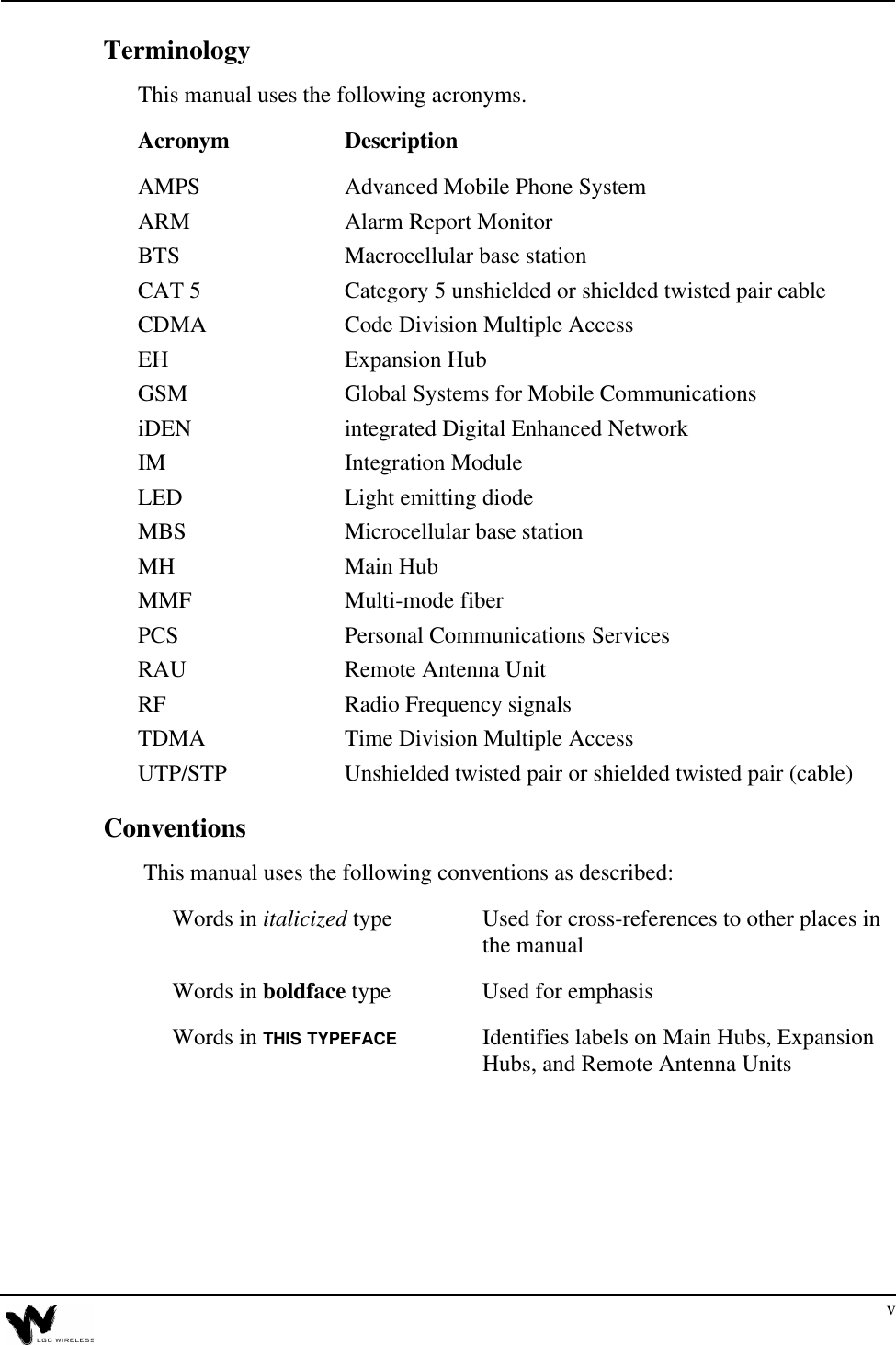


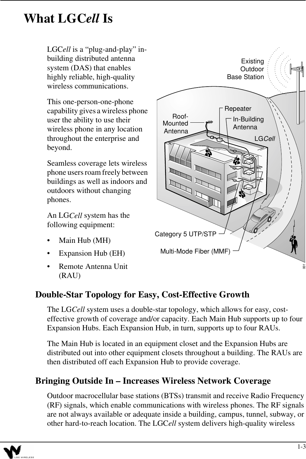

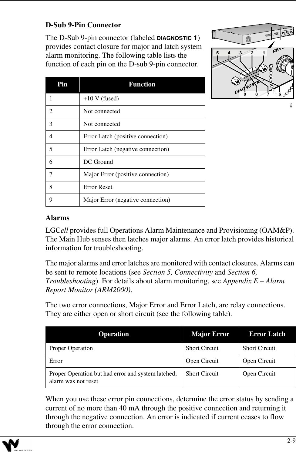
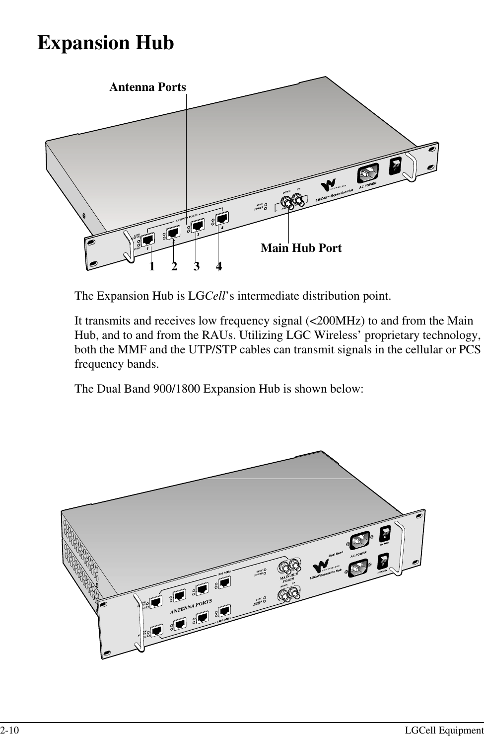
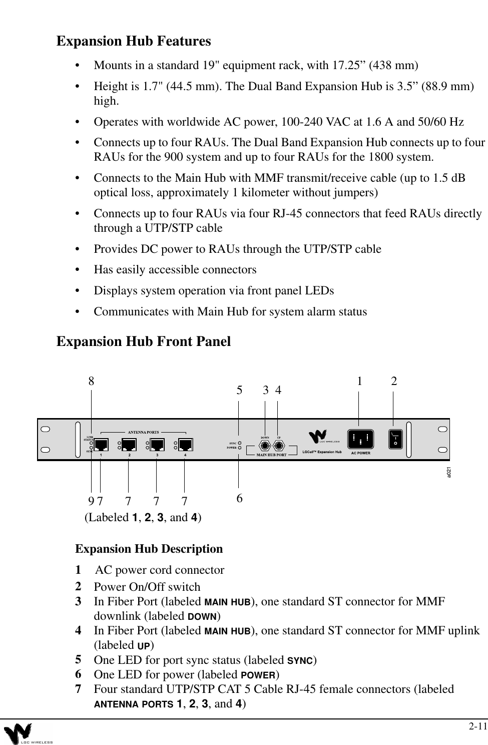
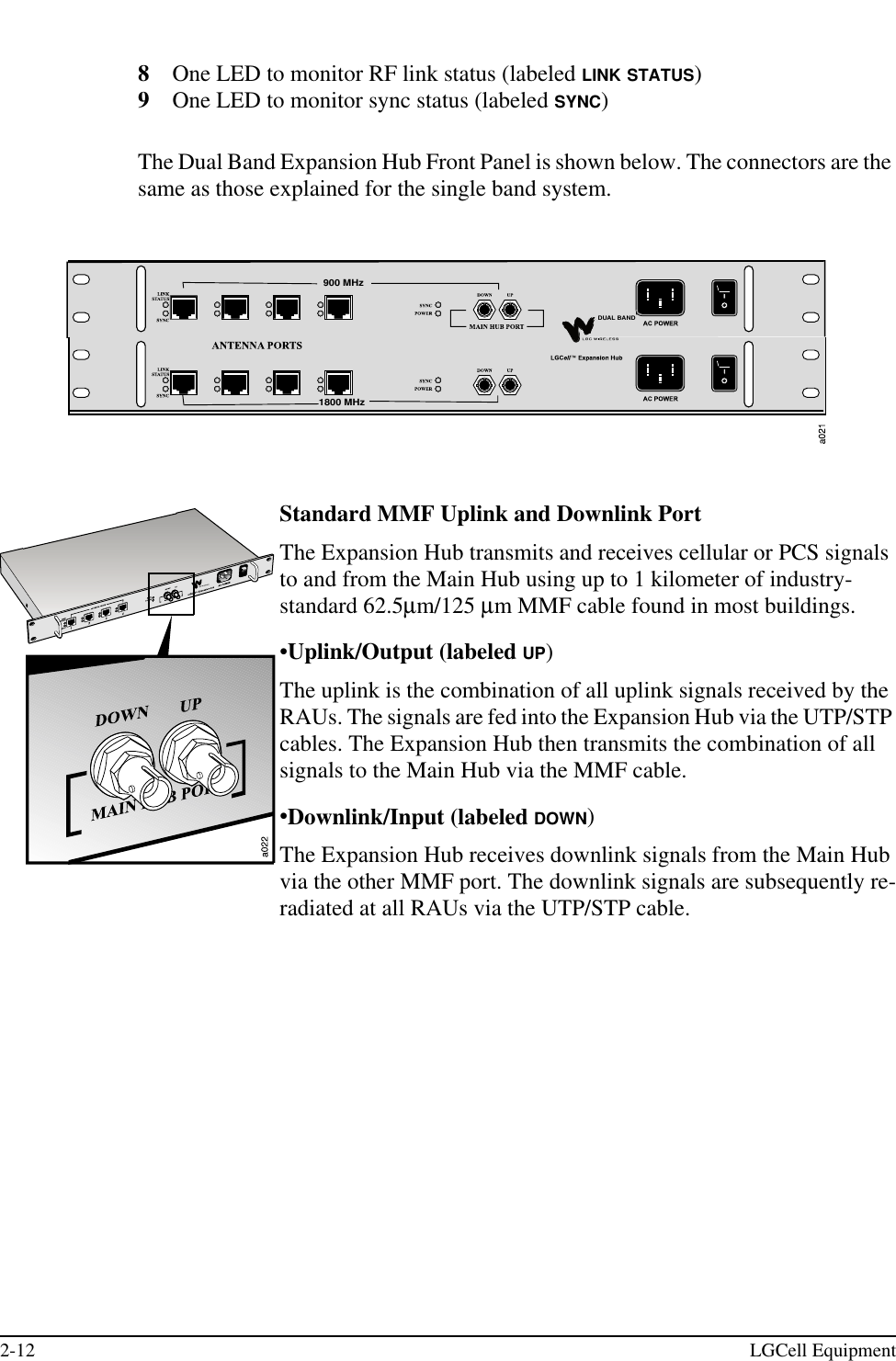
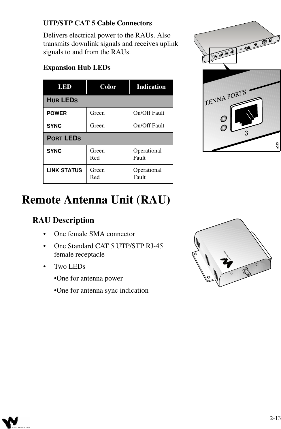
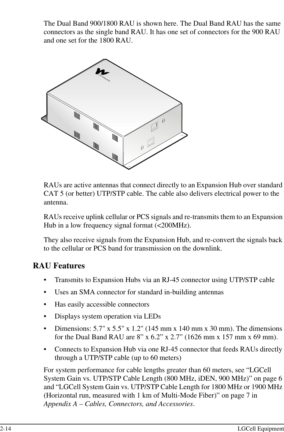
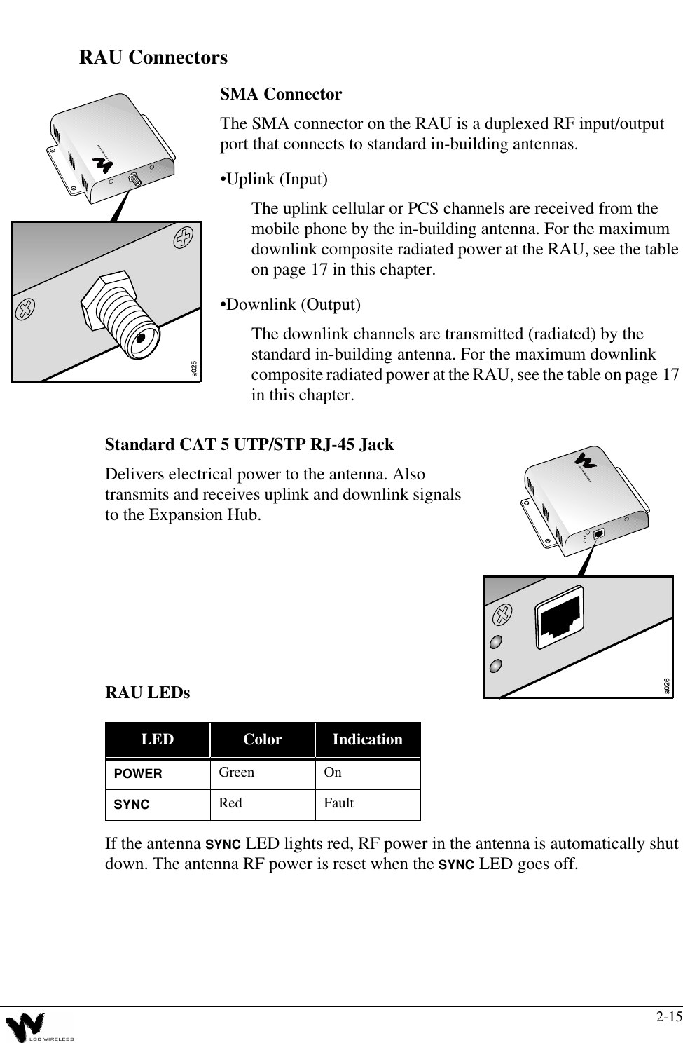
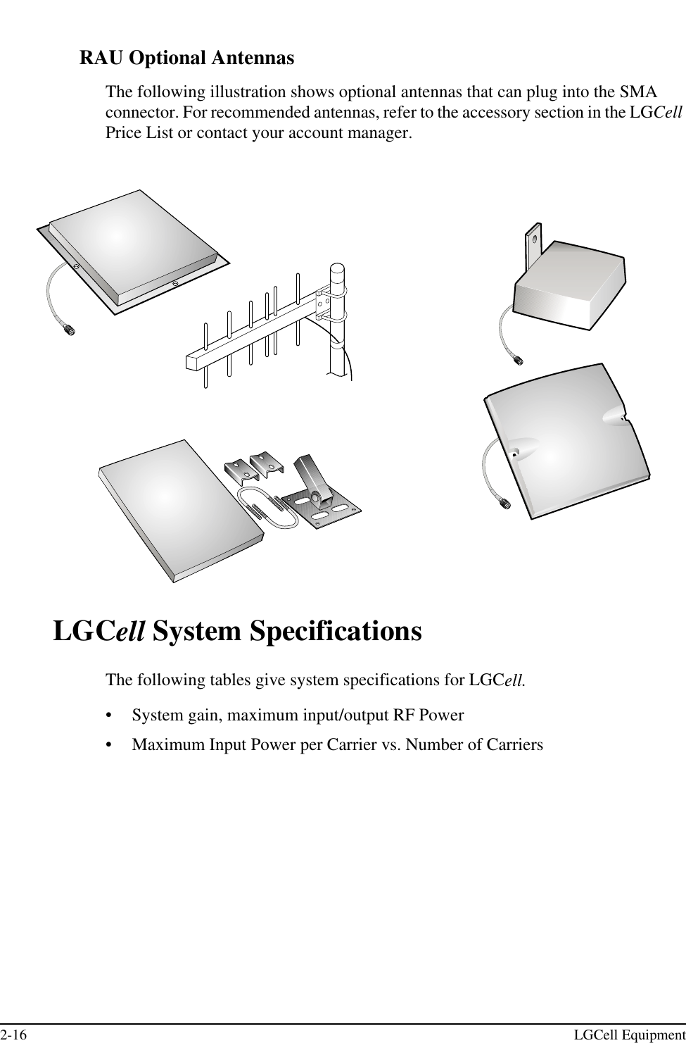
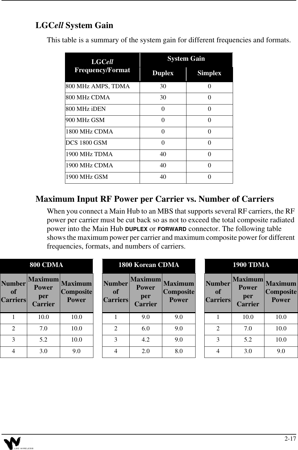

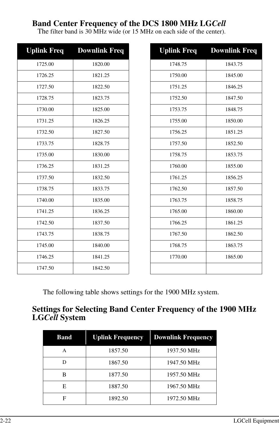

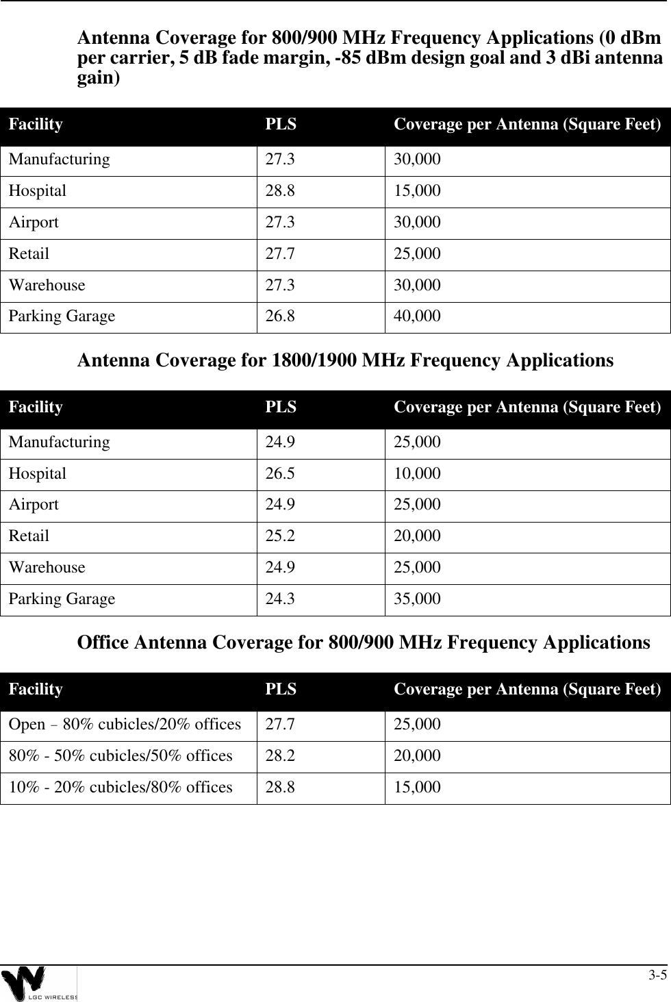
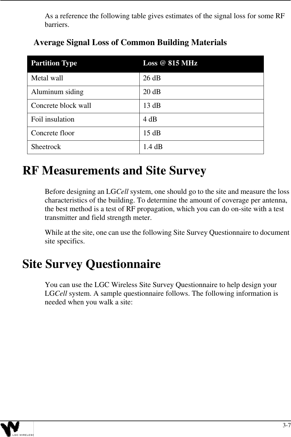
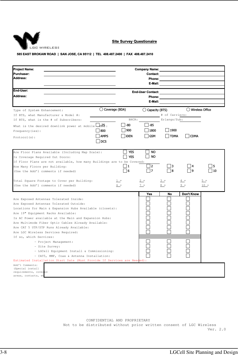
![3-6 LGCell Site Planning and DesignOffice Antenna Coverage for 1800/1900 MHz Frequency ApplicationsThe preceding tables show estimated clutter-defined path loss slope (PLS) for different frequencies at various kinds of sites. If you change the design goal or other parameters, these numbers will change based on the PLS.If the design parameters (output power per carrier, design goal, antenna gain, and fade margin) differ from those stated above, you can use the PLS value shown in the preceding tables in the following formula to estimate the area of coverage per antenna:The PLS is a general path loss number which takes into account free space loss and normal barriers to the RF signal. Severe obstructions such as metal, cement walls, or elevator shafts are best accounted for by a physical site survey. Facility PLS Coverage per Antenna (Square Feet)Open - 80% cubicles/20% offices 25.2 20,00080% - 50% cubicles/50% offices 25.7 15,00010% - 20% cubicles/80% offices 26.5 10,000Path Loss FormulasPath Loss (dB) = PLS * log 4πfD / cNote: Path Loss Slope = PLS dB/decade for free space loss D is the distance in metersf is the frequency in MHzc is the speed of lightPath Loss=Power per Carrier + Antenna Gain - Fade Margin - Design Goal (dBm)To convert feet to meters:Area = (D x 3.281)2 x πD = [10(Path Loss / PLS)] x [c / (4πf)]](https://usermanual.wiki/ADC-Telecommunications/DAS8-4-W.Part-1-Users-Manual/User-Guide-75176-Page-54.png)