ADC Telecommunications DAS8-4-W In-Building Distributed Antenna System User Manual J bonnie john front cover eps
ADC Telecommunications Inc. In-Building Distributed Antenna System J bonnie john front cover eps
Contents
- 1. Part 1 Users Manual
- 2. Part 2 Users Manual
- 3. Radiation Warning pages of user manual
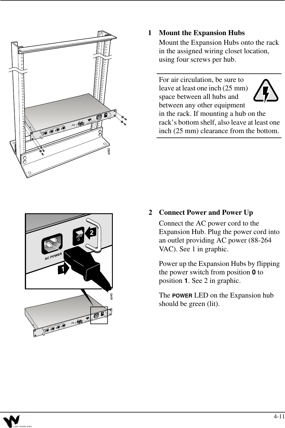
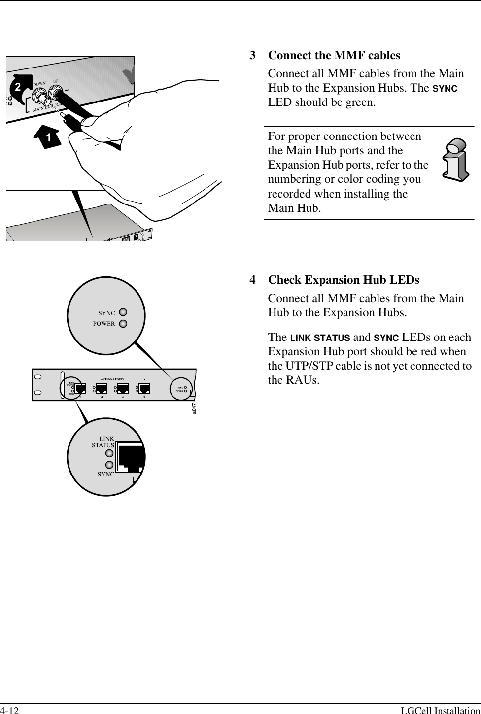
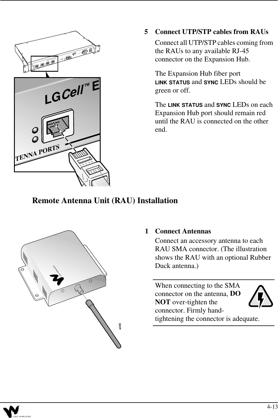
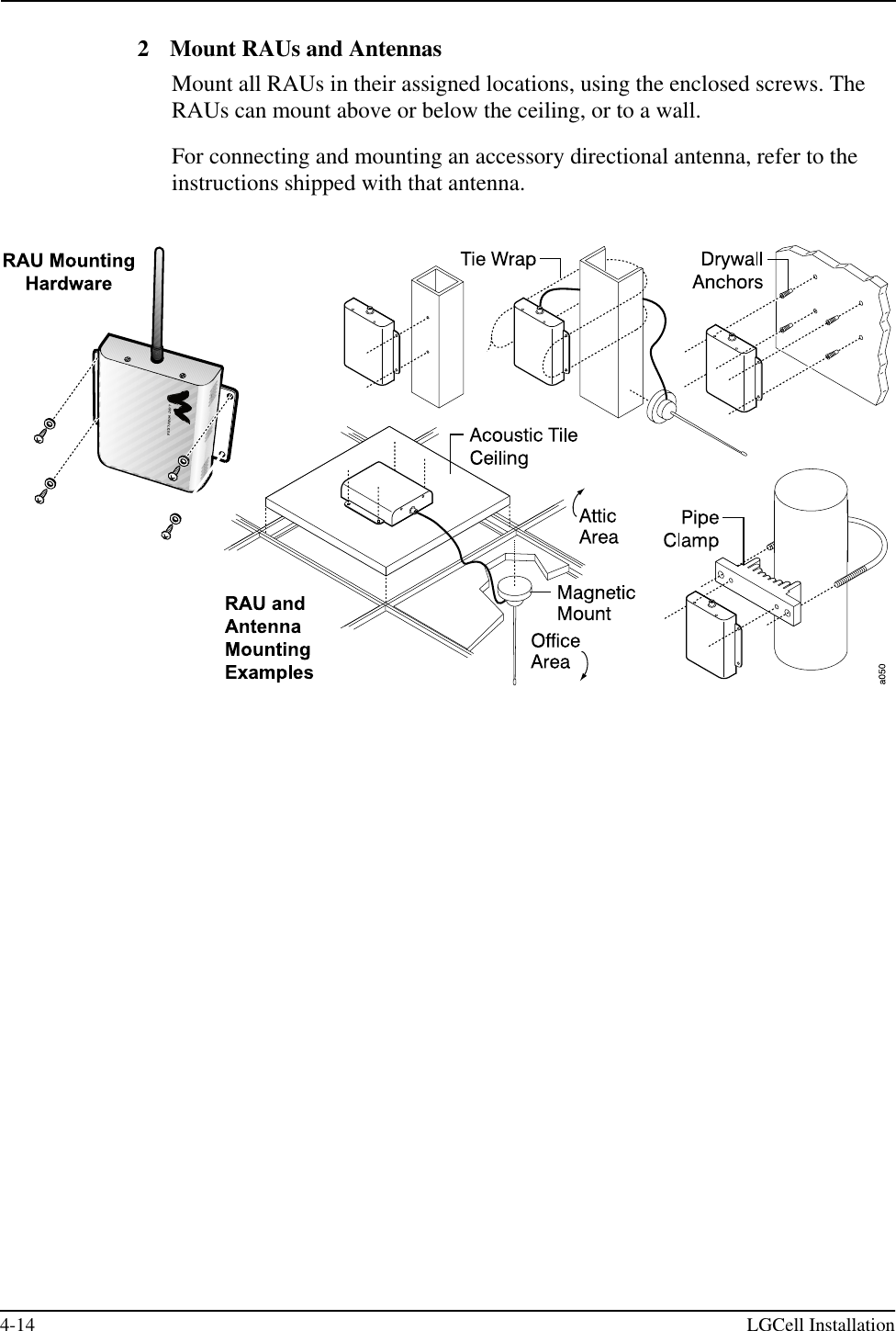
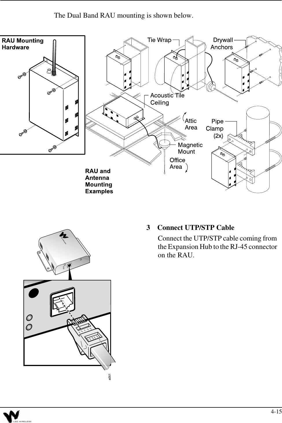
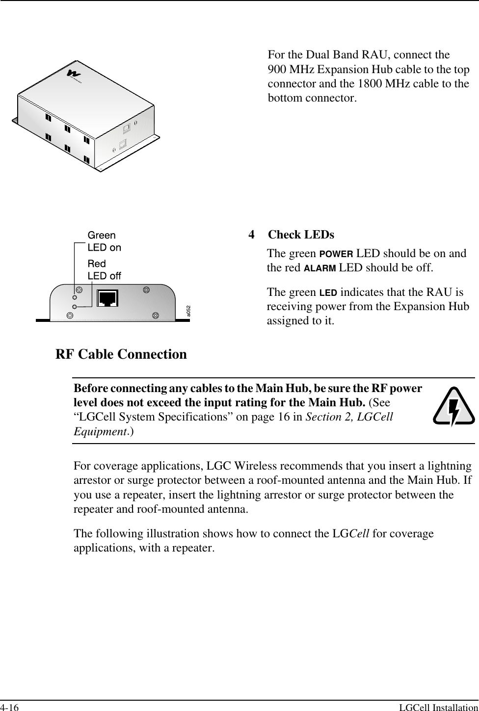
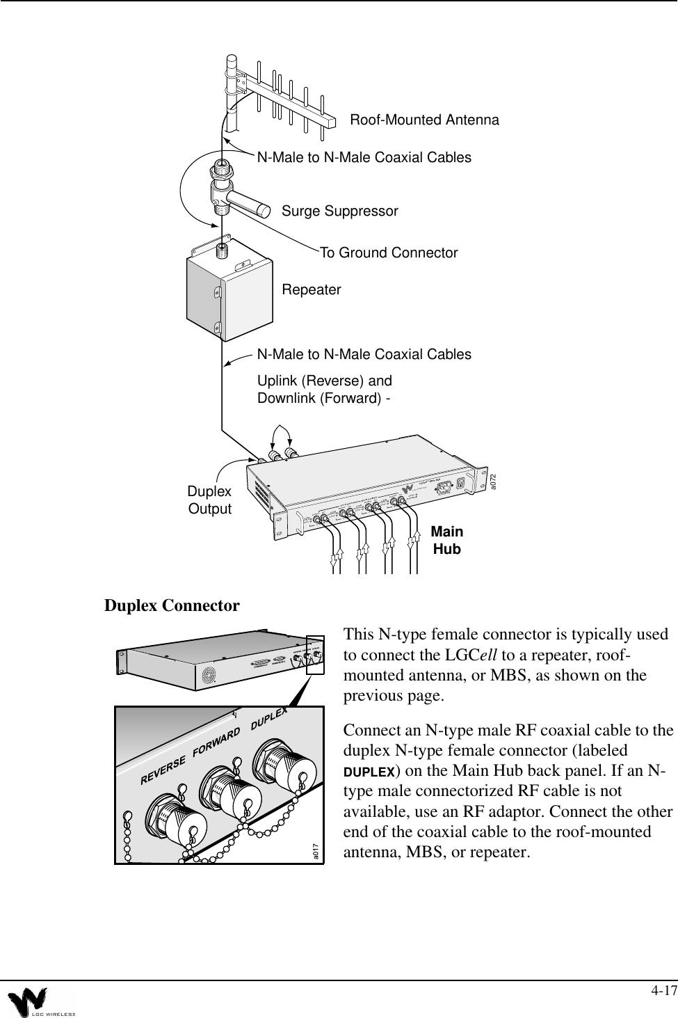
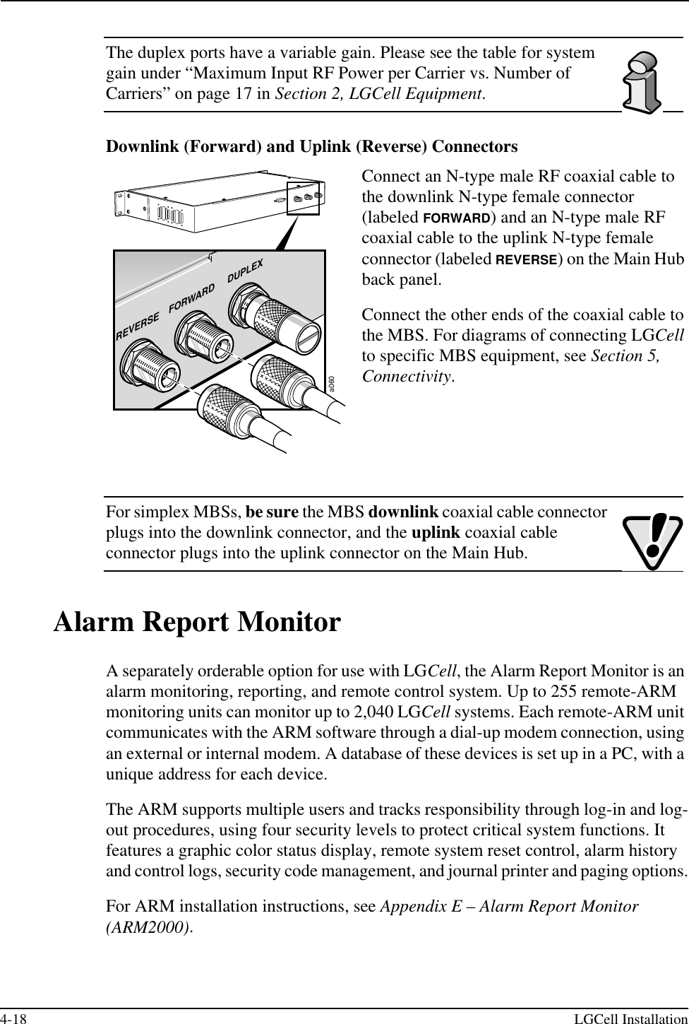
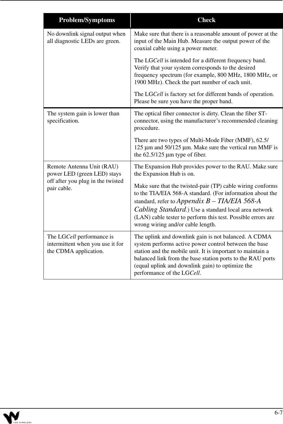
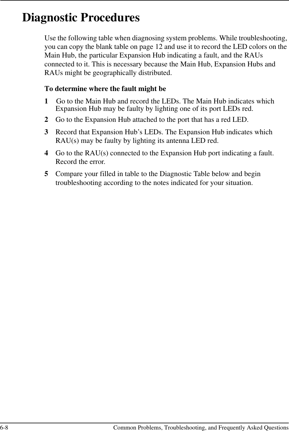
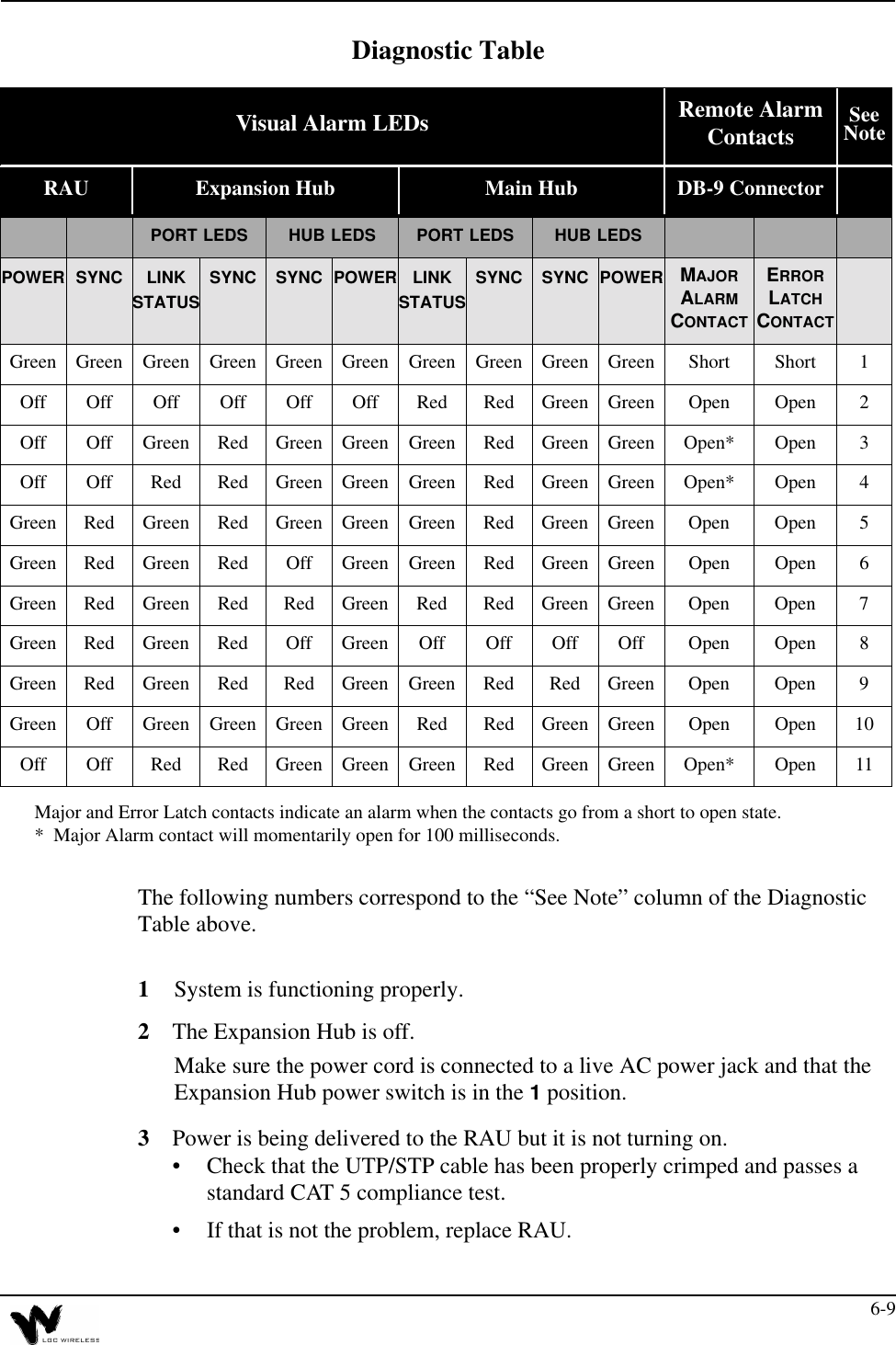
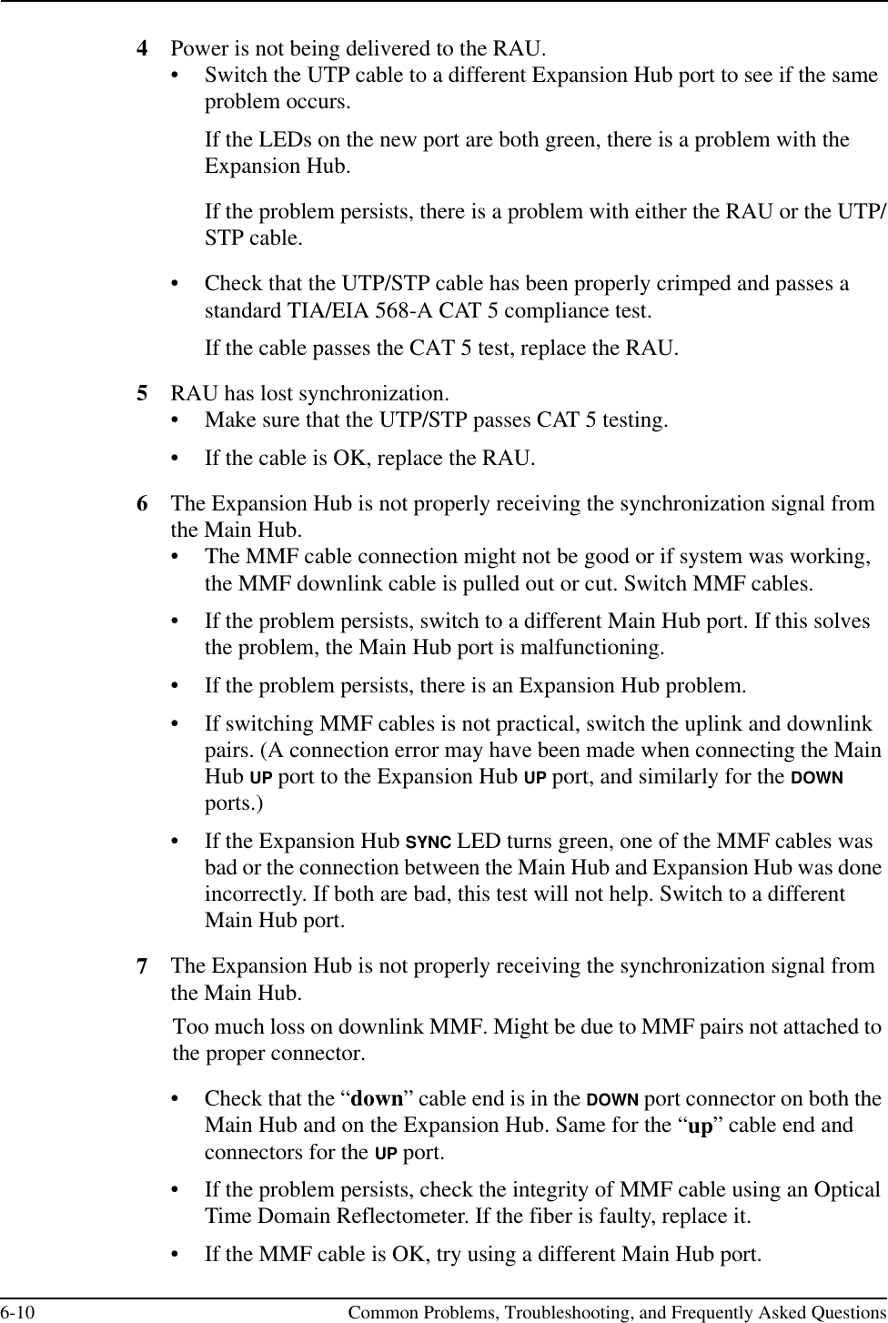
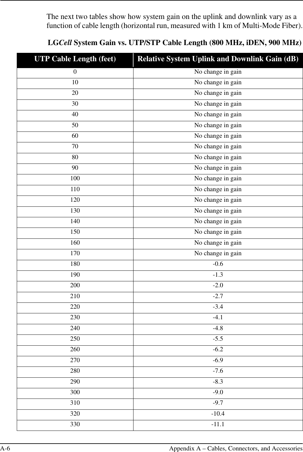
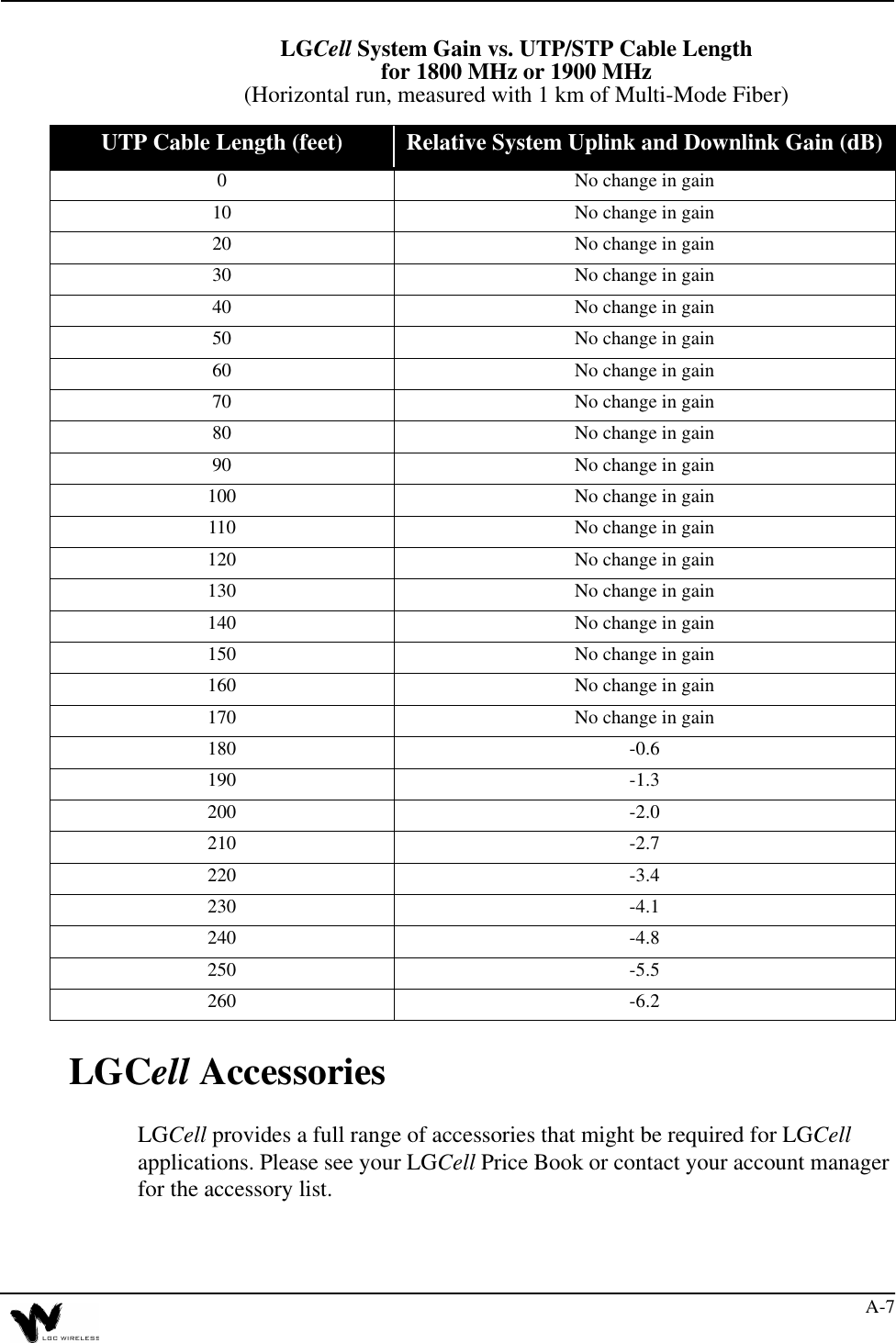
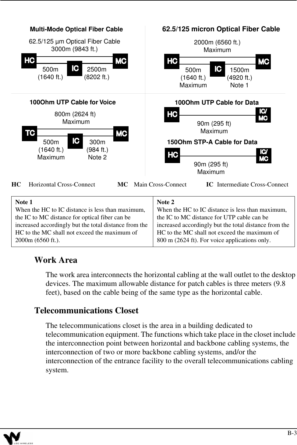
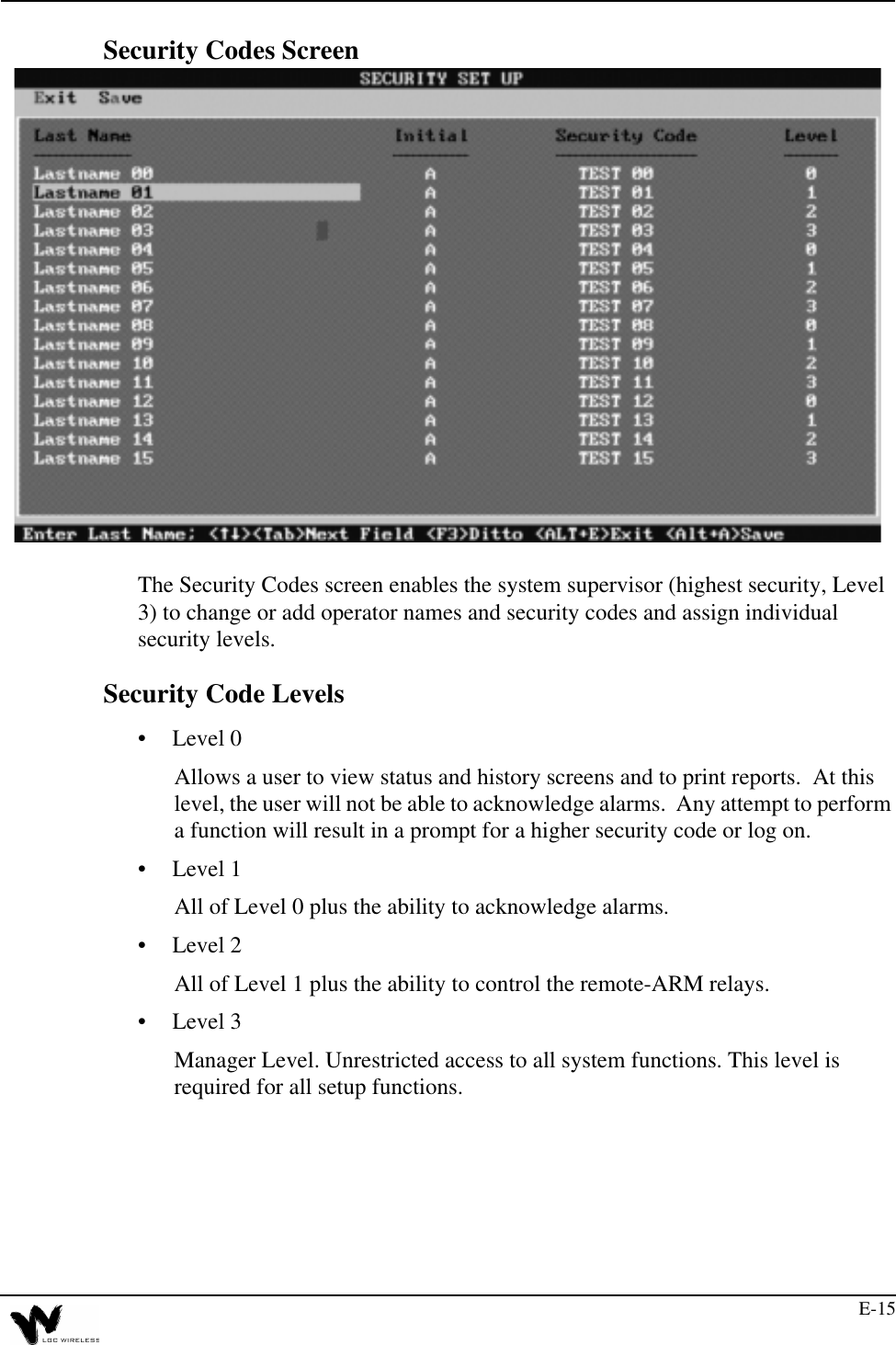
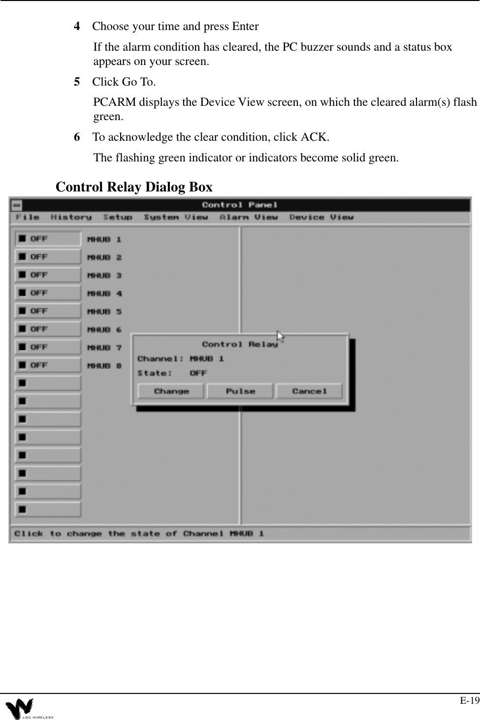
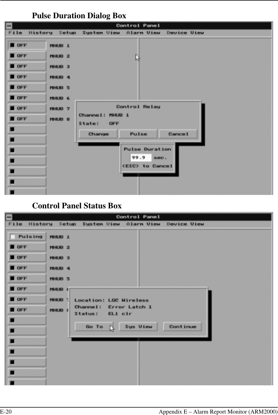
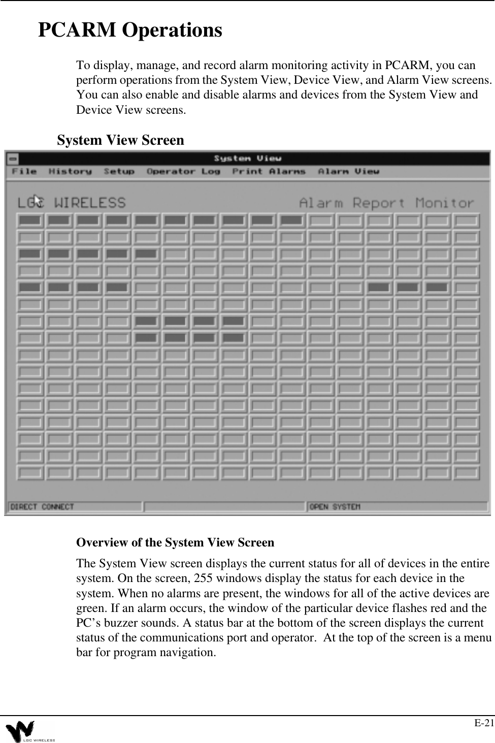
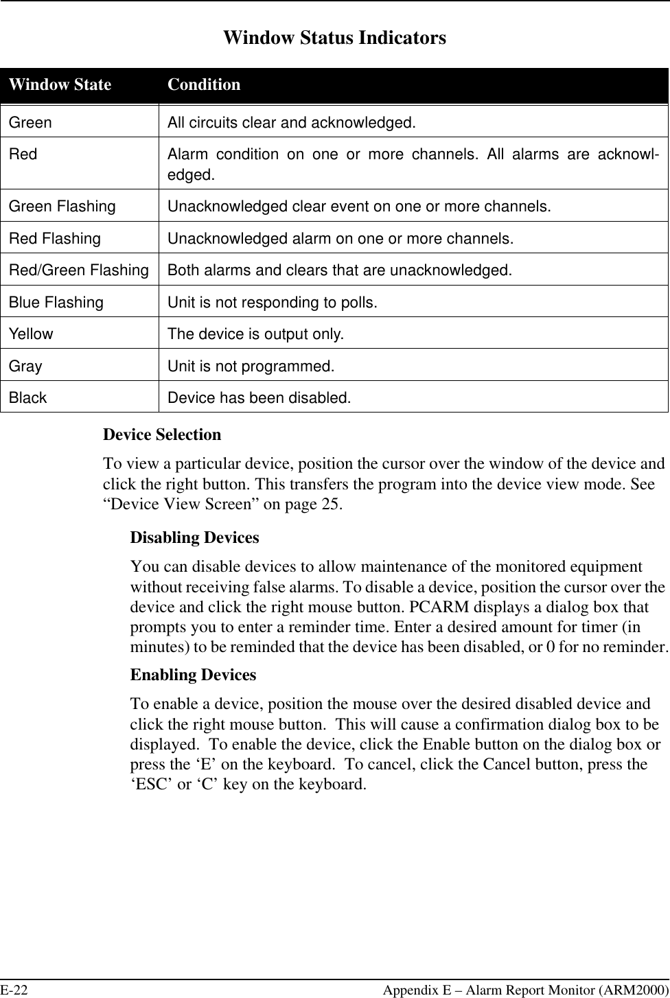
Part 2 Users Manual