ADC Telecommunications DAS8-4-W In-Building Distributed Antenna System User Manual J bonnie john front cover eps
ADC Telecommunications Inc. In-Building Distributed Antenna System J bonnie john front cover eps
Contents
- 1. Part 1 Users Manual
- 2. Part 2 Users Manual
- 3. Radiation Warning pages of user manual
Part 1 Users Manual
TM

This manual is produced for use by LGC Wireless personnel, licensees, and customers. The
information contained herein is the property of LGC Wireless. No part of this document may be
reproduced or transmitted in any form or by any means, electronic or mechanical, for any purpose,
without the express written permission of LGC Wireless.
LGC Wireless reserves the right to make changes, without notice, to the specifications and materials
contained herein, and shall not be responsible for any damages caused by reliance on the material as
presented, including, but not limited to, typographical and listing errors.
Your comments are welcome – they help us improve our products and documentation. Please
address your comments to LGC Wireless corporate headquarters in San Jose, CA, or call us at
1-800-530-9960 (U.S. customers) or +1-408-487-2400 (international customers).
© Copyright LGC Wireless, 1998 and 1999. Printed in USA. All rights reserved
Trademarks
All trademarks identified by ™ or ® are trademarks or registered trademark of LGC Wireless, Inc.
All other trademarks belong to their respective owners.
Limited Warranty
Seller warrants articles of its manufacture against defective materials or workmanship for a period
of one year from the date of shipment to Purchaser, except as provided in any warranty applicable
to Purchaser on or in the package containing the Goods (which warranty takes precedence over the
following warranty). The liability of Seller under the foregoing warranty is limited, at Seller’s
option, solely to repair or replacement with equivalent Goods, or an appropriate adjustment not to
exceed the sales price to Purchaser, provided that (a) Seller is notified in writing by Purchaser, within
the one year warranty period, promptly upon discovery of defects, with a detailed description of such
defects, (b) Purchaser has obtained a Return Materials Authorization (“RMA”) from Seller, which
RMA Seller agrees to provide Purchaser promptly upon request, (c) the defective Goods are returned
to Seller, transportation and other applicable charges prepaid by the Purchaser, and (d) Seller’s
examination of such Goods discloses to its reasonable satisfaction that defects were not caused by
negligence, misuse, improper installation, improper maintenance, accident or unauthorized repair or
alteration or any other cause outside the scope of Purchaser’s warranty made hereunder.
Notwithstanding the foregoing, Seller shall have the option to repair any defective Goods at
Purchaser’s facility. The original warranty period for any Goods that have been repaired or replaced
by seller will not thereby be extended. In addition, all sales will be subject to standard terms and
conditions on the sales contract.

LGC Wireless
LGC Wireless is a leading supplier of wireless solutions that enable mobile voice
and data communications and wireless Internet access throughout any facility. The
company’s wireless system, the LGCellTM, provides mobile users with highly
reliable access to high-quality voice and wireless data via cellular and PCS
networks throughout any private (corporation, university, hospital) or public
(airport, convention center, subway) facility.
LGC Wireless has received all type approvals for the LGCell, including the
European CE Mark, and is currently shipping product to more than 12 countries.
The LGCell supports all global wireless access standards including TDMA,
CDMA, AMPS, GSM and iDEN. LGC Wireless also offers a full range of
professional services to ensure cost effective and timely deployment of wireless
networks.
Your comments can assist us in improving our products and documentation. Please
address them to LGC Wireless, Inc.
LGC Wireless, Inc.
Address 585 East Brokaw Road
San Jose, California
95112-1017 USA
Phone 1-408-487-2400
Fax 1-408-487-2410
Help Hot Line (U.S. only) 1-800-530-9960
Net Address http://www.lgcwireless.com
e-mail info@lgcwireless.com


Table of Contents
About This Manual. . . . . . . . . . . . . . . . . . . . . . . . . . . . . . . . . . . . . . . . . . . . . . . . . . . . . . . . . . . . . iii
About LGCell . . . . . . . . . . . . . . . . . . . . . . . . . . . . . . . . . . . . . . . . . . . . . . . . . . . . . . . . . . . . . . . . . 1-1
What LGCell Is . . . . . . . . . . . . . . . . . . . . . . . . . . . . . . . . . . . . . . . . . . . . . . . . . . . . . . . . . . . . . . 1-3
LGCell Equipment. . . . . . . . . . . . . . . . . . . . . . . . . . . . . . . . . . . . . . . . . . . . . . . . . . . . . . . . . . . . 1-6
How LGCell Works . . . . . . . . . . . . . . . . . . . . . . . . . . . . . . . . . . . . . . . . . . . . . . . . . . . . . . . . . . . 1-10
LGCell Advantages . . . . . . . . . . . . . . . . . . . . . . . . . . . . . . . . . . . . . . . . . . . . . . . . . . . . . . . . . . . 1-11
What You Need to Do . . . . . . . . . . . . . . . . . . . . . . . . . . . . . . . . . . . . . . . . . . . . . . . . . . . . . . . . . 1-12
LGCell Equipment . . . . . . . . . . . . . . . . . . . . . . . . . . . . . . . . . . . . . . . . . . . . . . . . . . . . . . . . . . . . . 2-1
Standard Equipment. . . . . . . . . . . . . . . . . . . . . . . . . . . . . . . . . . . . . . . . . . . . . . . . . . . . . . . . . . . 2-3
Main Hub . . . . . . . . . . . . . . . . . . . . . . . . . . . . . . . . . . . . . . . . . . . . . . . . . . . . . . . . . . . . . . . . . . . 2-3
Expansion Hub. . . . . . . . . . . . . . . . . . . . . . . . . . . . . . . . . . . . . . . . . . . . . . . . . . . . . . . . . . . . . . . 2-10
Remote Antenna Unit (RAU) . . . . . . . . . . . . . . . . . . . . . . . . . . . . . . . . . . . . . . . . . . . . . . . . . . . 2-13
LGCell System Specifications. . . . . . . . . . . . . . . . . . . . . . . . . . . . . . . . . . . . . . . . . . . . . . . . . . . 2-16
Band Selective Option . . . . . . . . . . . . . . . . . . . . . . . . . . . . . . . . . . . . . . . . . . . . . . . . . . . . . . . . . 2-20
LGCell Site Planning and Design . . . . . . . . . . . . . . . . . . . . . . . . . . . . . . . . . . . . . . . . . . . . . . . . . 3-1
Project Management . . . . . . . . . . . . . . . . . . . . . . . . . . . . . . . . . . . . . . . . . . . . . . . . . . . . . . . . . . 3-3
RF Coverage Estimate for a Site . . . . . . . . . . . . . . . . . . . . . . . . . . . . . . . . . . . . . . . . . . . . . . . . . 3-4
RF Measurements and Site Survey . . . . . . . . . . . . . . . . . . . . . . . . . . . . . . . . . . . . . . . . . . . . . . . 3-7
Site Survey Questionnaire . . . . . . . . . . . . . . . . . . . . . . . . . . . . . . . . . . . . . . . . . . . . . . . . . . . . . . 3-7
LGCell Installation. . . . . . . . . . . . . . . . . . . . . . . . . . . . . . . . . . . . . . . . . . . . . . . . . . . . . . . . . . . . . 4-1
System Requirements. . . . . . . . . . . . . . . . . . . . . . . . . . . . . . . . . . . . . . . . . . . . . . . . . . . . . . . . . . 4-3
LGCell Standard Equipment . . . . . . . . . . . . . . . . . . . . . . . . . . . . . . . . . . . . . . . . . . . . . . . . . . . . 4-5
LGCell Equipment Installation . . . . . . . . . . . . . . . . . . . . . . . . . . . . . . . . . . . . . . . . . . . . . . . . . . 4-5
Alarm Report Monitor . . . . . . . . . . . . . . . . . . . . . . . . . . . . . . . . . . . . . . . . . . . . . . . . . . . . . . . . . 4-18
Connectivity . . . . . . . . . . . . . . . . . . . . . . . . . . . . . . . . . . . . . . . . . . . . . . . . . . . . . . . . . . . . . . . . . . 5-1
Connecting Multiple LGCell Systems . . . . . . . . . . . . . . . . . . . . . . . . . . . . . . . . . . . . . . . . . . . . 5-3
Connecting two LGCells . . . . . . . . . . . . . . . . . . . . . . . . . . . . . . . . . . . . . . . . . . . . . . . . . . . . . . . 5-3
Connecting More Than Two LGCells . . . . . . . . . . . . . . . . . . . . . . . . . . . . . . . . . . . . . . . . . . . . . 5-4
Connecting LGCell to Base Stations, Microcells, or Picocells . . . . . . . . . . . . . . . . . . . . . . . . . . 5-4
Common Problems, Troubleshooting, and Frequently Asked Questions . . . . . . . . . . . . . . . . 6-1
Common Problems and Troubleshooting . . . . . . . . . . . . . . . . . . . . . . . . . . . . . . . . . . . . . . . . . . 6-3
LED Indicator Description. . . . . . . . . . . . . . . . . . . . . . . . . . . . . . . . . . . . . . . . . . . . . . . . . . . . . . 6-4
Troubleshooting Guidelines. . . . . . . . . . . . . . . . . . . . . . . . . . . . . . . . . . . . . . . . . . . . . . . . . . . . . 6-6
Diagnostic Procedures . . . . . . . . . . . . . . . . . . . . . . . . . . . . . . . . . . . . . . . . . . . . . . . . . . . . . . . . . 6-8
Frequently Asked Questions . . . . . . . . . . . . . . . . . . . . . . . . . . . . . . . . . . . . . . . . . . . . . . . . . . . . 6-13

ii Table of Contents
Appendix A – Cables, Connectors, and Accessories . . . . . . . . . . . . . . . . . . . . . . . . . . . . . . . . . . A-1
Cables and Connectors. . . . . . . . . . . . . . . . . . . . . . . . . . . . . . . . . . . . . . . . . . . . . . . . . . . . . . . . . A-3
LGCell Accessories . . . . . . . . . . . . . . . . . . . . . . . . . . . . . . . . . . . . . . . . . . . . . . . . . . . . . . . . . . . A-7
Appendix B – TIA/EIA 568-A Cabling Standard . . . . . . . . . . . . . . . . . . . . . . . . . . . . . . . . . . . . B-1
Appendix C – Compliance Information . . . . . . . . . . . . . . . . . . . . . . . . . . . . . . . . . . . . . . . . . . . C-1
IEC/EN 60825-2 - Safe Use of Optical Fiber Communication Systems. . . . . . . . . . . . . . . . . . . C-6
Appendix D – Services. . . . . . . . . . . . . . . . . . . . . . . . . . . . . . . . . . . . . . . . . . . . . . . . . . . . . . . . . . D-1
Appendix E – Alarm Report Monitor (ARM2000) . . . . . . . . . . . . . . . . . . . . . . . . . . . . . . . . . . . E-1
Description of the ARM2000 System . . . . . . . . . . . . . . . . . . . . . . . . . . . . . . . . . . . . . . . . . . . . . E-3
ARM2000 System Basics . . . . . . . . . . . . . . . . . . . . . . . . . . . . . . . . . . . . . . . . . . . . . . . . . . . . . . E-4
ARM2000-RU (Remote Unit) Installation . . . . . . . . . . . . . . . . . . . . . . . . . . . . . . . . . . . . . . . . . E-4
PCARM Installation for ARM2000. . . . . . . . . . . . . . . . . . . . . . . . . . . . . . . . . . . . . . . . . . . . . . . E-7
Security Setup . . . . . . . . . . . . . . . . . . . . . . . . . . . . . . . . . . . . . . . . . . . . . . . . . . . . . . . . . . . . . . . E-12
Alarm and Device Setup . . . . . . . . . . . . . . . . . . . . . . . . . . . . . . . . . . . . . . . . . . . . . . . . . . . . . . . E-16
PCARM Operations. . . . . . . . . . . . . . . . . . . . . . . . . . . . . . . . . . . . . . . . . . . . . . . . . . . . . . . . . . . E-21
Reports. . . . . . . . . . . . . . . . . . . . . . . . . . . . . . . . . . . . . . . . . . . . . . . . . . . . . . . . . . . . . . . . . . . . . E-28
LGCell Installation Procedure
This section shows the steps involved in installing an LGCell system.
For a detailed description of LGCell installation procedures, refer to
Section 4, LGCell Installation.
If you plan to connect your LGCell system to more than one radio or base
station, you also need the Integration Module Installation and Reference
Manual.
Install LGCell equipment in the wiring, telecom, or electrical closet(s) indicated on
your site installation plan. LGC Wireless provides the following equipment and
supplies for installation:
•LGCell Main Hub(s), each with two rack mount elbow brackets and four rack
mount screws
•LGCell Expansion Hub(s), each with two rack mount elbow brackets and four
rack mount screws
•Remote Antenna Unit(s) (RAUs) and in-building antenna(s), with four
mounting screws for each RAU
•LGCell Installation and Reference Guide
•Optionally, Integration Module Installation and Reference Manual
You also need the following equipment and supplies:
•Cable and connectors already installed and terminated. LGC Wireless
recommends plenum-rated Category 5 (CAT 5) or better, Unshielded Twisted
Pair or Shielded Twisted Pair (UTP/STP) and Multi-Mode Fiber (MMF) cable.
•AC power supply (100-240 VAC at 1.6 A and 50/60 Hz) available for each
Main Hub
•19” equipment rack space in the wiring closet
•Phillips screwdriver
•MMF cleaner recommended by the cable manufacturer
Inspect the equipment and supplies before you start the LGCell installation. Make
sure that the UTP/STP and MMF cables are terminated correctly and that the
connectors are clean and free of dust or oil (use recommended cleaner as necessary).
If you have any problems, call LGC Wireless at 1-800-530-9960 (U.S. customers)
or +1-408-487-2400 (international customers).

ii LGCell Installation Procedure
The procedure for installing the LGCell system follows. Section 4, LGCell
Installation, describes the installation procedure in detail.
A. Main Hub Installation
1Mount one or more LGCell Main Hubs in an equipment rack in the assigned
wiring closet location, using the four screws provided for each hub.
2Connect the AC power to each Main Hub and power up the hub.
3Connect two clean MMF cables to each Main Hub port.
4Check the Main Hub Sync and Link Status LEDs (connected = green, not
connected = red).
5Connect the RF cable from the antenna(s) to the Main Hub(s) (for a roof-
mounted antenna, insert a lightning arrestor or surge protector).
B. Expansion Hub Installation
1Mount one or more LGCell Expansion Hubs in the equipment rack, using the
four screws provided for each hub.
2Connect the AC power to each Expansion Hub and power up the hub.
3Connect all MMF cables from the Main Hub(s) to the Expansion Hub(s).
4Check the Expansion Hub Sync and Link Status LEDs (connected = green, not
connected = red)
5Connect CAT 5 cable to the respective ports
C. RAU and Antenna Installation
1Mount the RAU(s) and antenna(s).
2Connect the UTP/STP cables from the Expansion Hubs to the RJ-45
connectors on the RAU(s).
3Connect an accessory antenna to each RAU SMA connector.
4Check the LEDs on the RAU(s). If not connected properly or sync is not
achieved, then one LED will be red. When connected, one LED should be
green and the other not lit.
D. System Monitoring using the ARM (if provisioned)
1Install the Alarm Report Monitor (ARM) panel adjacent to the Main Hubs.
2Connect the octopus cable to the connector on the ARM.
3Connect one DB9 connector from the octopus cable to each ARM unit.
4Set the dip switch in the ARM to the appropriate ID number.
5Connect the ARM unit to a local PSTN line.
6Install the ARM system software on a PC at the NOC.
7Configure the software and dial into the ARM unit to set its parameters (dial-in
number, and so on).
About This Manual
This Installation and Reference Manual describes the following LGCell products:
•LGCell 800 MHz AMPS/TDMA/CDMA/iDEN
•LGCell 900 MHz GSM
•LGCell 1800 MHz DCS
•LGCell 1800 MHz Korean PCS
•LGCell 1900 MHz TDMA/CDMA/GSM
•LGCell Dual Band 900 GSM/1800 DCS
System operation for these products is identical. The only differences between the
products are the operating frequency range, access scheme (TDMA, GSM, etc.) and
certain operating parameters (gain, etc.). In this manual, distinctions between
different systems are clearly indicated.
This section provides an overview of this Installation and Reference Manual,
describes conventions, and provides other useful information.
If you plan to connect your LGCell system to more than one radio or base
station, you also need the Integration Module Installation and Reference
Manual.
Overview
This manual provides information to prepare for and install the LGCell equipment.
The following steps need to be taken:
•RF engineering and system design
•Equipment purchasing
•Cable preparation
•Equipment installation and commissioning

iv About This Manual
This manual has six sections and five appendixes:
1About LGCell Describes the LGCell’s functions, applications,
components and its advantages.
2LGCell Equipment Describes the standard LGCell equipment and
operation and provides System Specifications.
3LGCell Site Planning Contains information about pre-installation
and Design preparation and project management from site
planning through LGCell installation. The tasks
involved and an estimated timetable are provided.
4LGCell Installation Describes system requirements, lists standard
equipment, and gives LGCell equipment installation
procedures.
5 Connectivity Contains Maximum Input/Output RF Power and RF
Power per Carrier tables and describes how to connect
multiple LGCell systems.
6 Common Problems, Describes how to diagnose and solve operational
Troubleshooting, and problems and gives answers to questions that
Frequently Asked customers ask frequently.
Questions
Appendix A – Cables, Contains information about cables, connectors,
Connectors and and accessories for LGCell applications.
Accessories
Appendix B – Contains information about standards for
TIA/EIA 568-A in-building cabling.
Cabling Standards
Appendix C – Provides system approval status and regulatory
Compliance notices for various countries.
Information
Appendix D – Services Lists the services that LGC Wireless can provide
for customers.
Appendix E – Alarm Describes the ARM2000 system, which can be used
Report Monitor to monitor LGCell alarms.
(ARM2000)

v
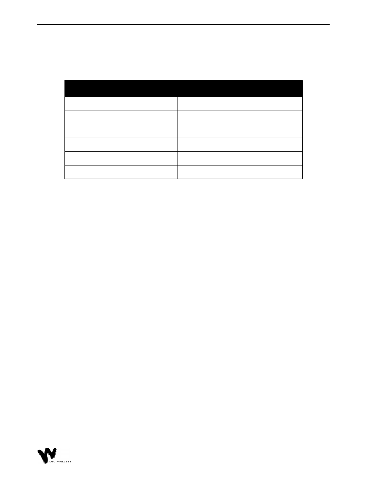
Terminology
This manual uses the following acronyms.
Acronym Description
AMPS Advanced Mobile Phone System
ARM Alarm Report Monitor
BTS Macrocellular base station
CAT 5 Category 5 unshielded or shielded twisted pair cable
CDMA Code Division Multiple Access
EH Expansion Hub
GSM Global Systems for Mobile Communications
iDEN integrated Digital Enhanced Network
IM Integration Module
LED Light emitting diode
MBS Microcellular base station
MH Main Hub
MMF Multi-mode fiber
PCS Personal Communications Services
RAU Remote Antenna Unit
RF Radio Frequency signals
TDMA Time Division Multiple Access
UTP/STP Unshielded twisted pair or shielded twisted pair (cable)
Conventions
This manual uses the following conventions as described:
Words in italicized type Used for cross-references to other places in
the manual
Words in boldface type Used for emphasis
Words in THIS TYPEFACE Identifies labels on Main Hubs, Expansion
Hubs, and Remote Antenna Units
vi About This Manual
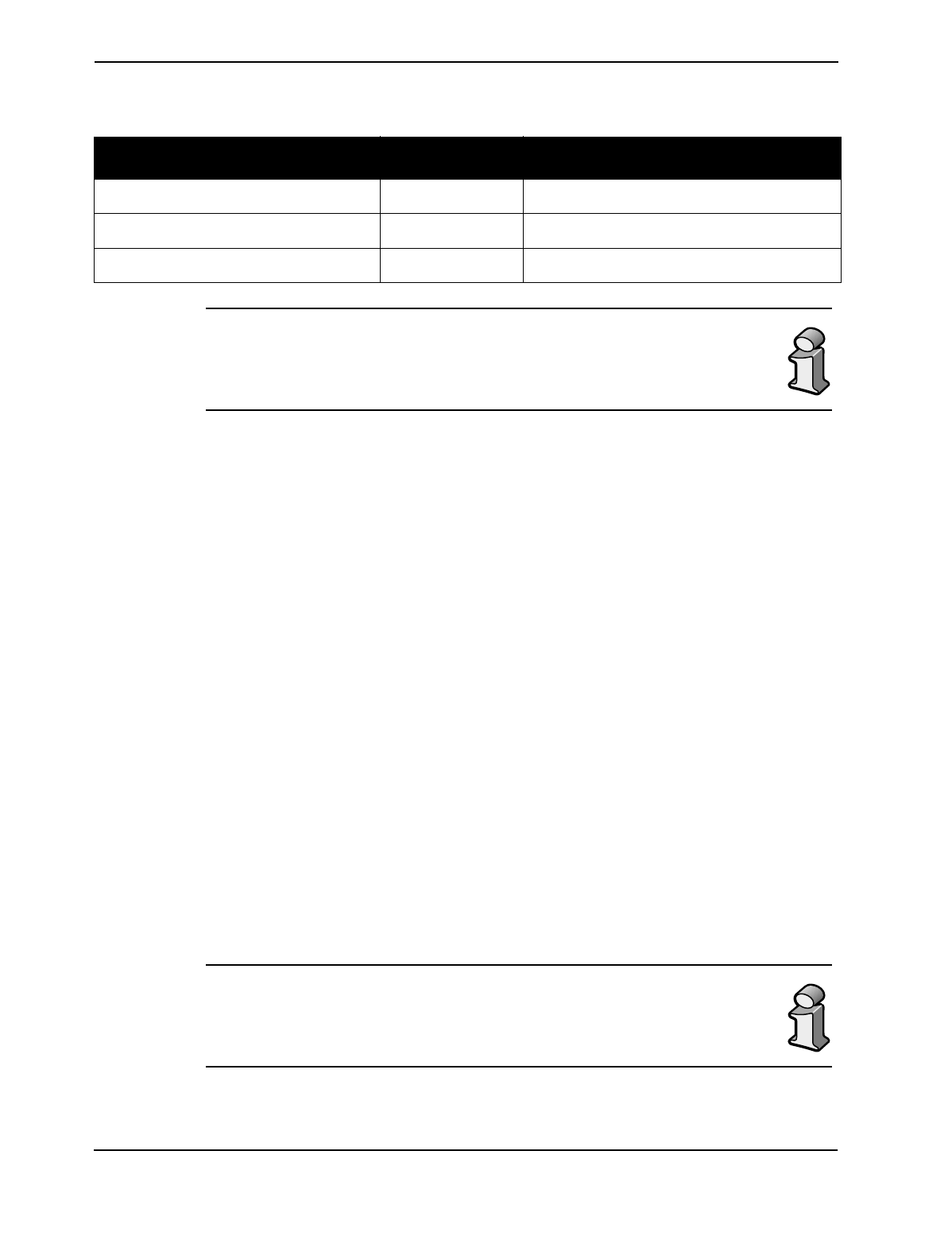
This manual uses the following symbols as described.
This symbol represents additional INFORMATION.
It is used to emphasize text with unusual importance, special
significance, or to provide supplemental information.
This symbol represents CAUTION.
It alerts users that a given action or omitted action can cause or
contribute to a hazardous condition. Damage to the equipment can
occur.
This symbol represents WARNING.
It appears when a given action or omitted action can result in
catastrophic damage to the equipment or cause injury to the user.
Precautions
This section describes general safety precautions for LGCell products and safety
precautions for Fiber Ports on the hubs.
General Safety Precautions
The following precautions apply to LGCell products.
•LGCell has no user-serviceable parts. Faulty or failed units are fully
replaceable through LGC Wireless. Please contact us at 1-800-530-9960. For
international customers, please contact us at +1-408-487-2400.
•Never input an RF signal to the Main Hub Duplex port that is higher than those
defined on page 17 in Section 2, LGCell Equipment.
•Although modeled after an Ethernet/LAN-like architecture and connectivity,
LGCell units (Main Hub, Expansion Hub, and the Remote Antenna Unit) are
not intended to connect to Ethernet data hubs, routers, cards or other similar
data equipment.
•For improved air circulation, be sure to leave at least one inch (25 mm) of
space between all hubs and between any other equipment in the rack. If
mounting a hub on the rack’s bottom shelf, also leave at least a one inch of
clearance from the bottom.
vii
•When you connect the Multi-Mode Fiber (MMF) Optical Cable, take the same
precaution as if installing Ethernet network equipment. All optical fiber ST
connectors should be cleaned according to the cable manufacturer’s
instructions.
•When you connect a radiating antenna to an RAU, DO NOT over-tighten the
SMA connector. Firmly hand-tightening the connector is adequate.
To reduce the risk of fire or electric shock, do not expose this
equipment to rain or moisture.
Fiber Port Safety Precautions
Suggested safety precautions for working with LGCell Fiber Ports follow. For
information about LGCell compliance with safety standards, see Appendix C –
Compliance Information.
•Viewing fiber: Observe the following warning about viewing fiber ends in
ports.
Do not stare with unprotected eyes at the connector ends of the fibers
or the ports of the hubs.Invisible infrared radiation is present at the
front panel of the Main Hub and Expansion Hub. Do not remove the
Fiber Port dust cover unless the port is in use. Do not stare directly
into a Fiber Port.
•Test fiber cables: When you use test fiber optical cables, connect the optical
power source last and disconnect it first.
•Fiber ends: Cover any unconnected fiber ends with an approved cap. Do not
use tape.
•Broken fiber cables: Do not stare with unprotected eyes at any broken ends of
the fibers. Report any broken fiber cables and have them replaced.
•Cleaning: Use only approved methods for cleaning optical fiber connectors.
•Modifications: Do not make any unauthorized modifications to this fiber
optical system or associated equipment.
•Live work: Live work is permitted on the LGCell as it is a Class 1 hazard.
•Signs: No warning signs are required.
•Test equipment: Use Class 1 test equipment.

viii About This Manual

1About LGCell
This section is an overview of the LGCell. It gives a brief description of the system
and applications, the LGCell equipment, how it works, why it’s better than the
competition, and what you need to do to install the system.
Later sections of this Installation and Reference Manual contain a detailed
description of the LGCell system.
Contents
About LGCell
What LGCell Is . . . . . . . . . . . . . . . . . . . . . . . . . . . . . . . . . . . . . . . . . . . . . . . . . . . 3
LGCell Equipment. . . . . . . . . . . . . . . . . . . . . . . . . . . . . . . . . . . . . . . . . . . . . . . . . 6
How LGCell Works. . . . . . . . . . . . . . . . . . . . . . . . . . . . . . . . . . . . . . . . . . . . . . . 10
LGCell Advantages . . . . . . . . . . . . . . . . . . . . . . . . . . . . . . . . . . . . . . . . . . . . . . . 11
What You Need to Do . . . . . . . . . . . . . . . . . . . . . . . . . . . . . . . . . . . . . . . . . . . . . 12

1-2 About LGCell
1-3
What LGCell Is
LGCell is a “plug-and-play” in-
building distributed antenna
system (DAS) that enables
highly reliable, high-quality
wireless communications.
This one-person-one-phone
capability gives a wireless phone
user the ability to use their
wireless phone in any location
throughout the enterprise and
beyond.
Seamless coverage lets wireless
phone users roam freely between
buildings as well as indoors and
outdoors without changing
phones.
An LGCell system has the
following equipment:
•Main Hub (MH)
•Expansion Hub (EH)
•Remote Antenna Unit
(RAU)
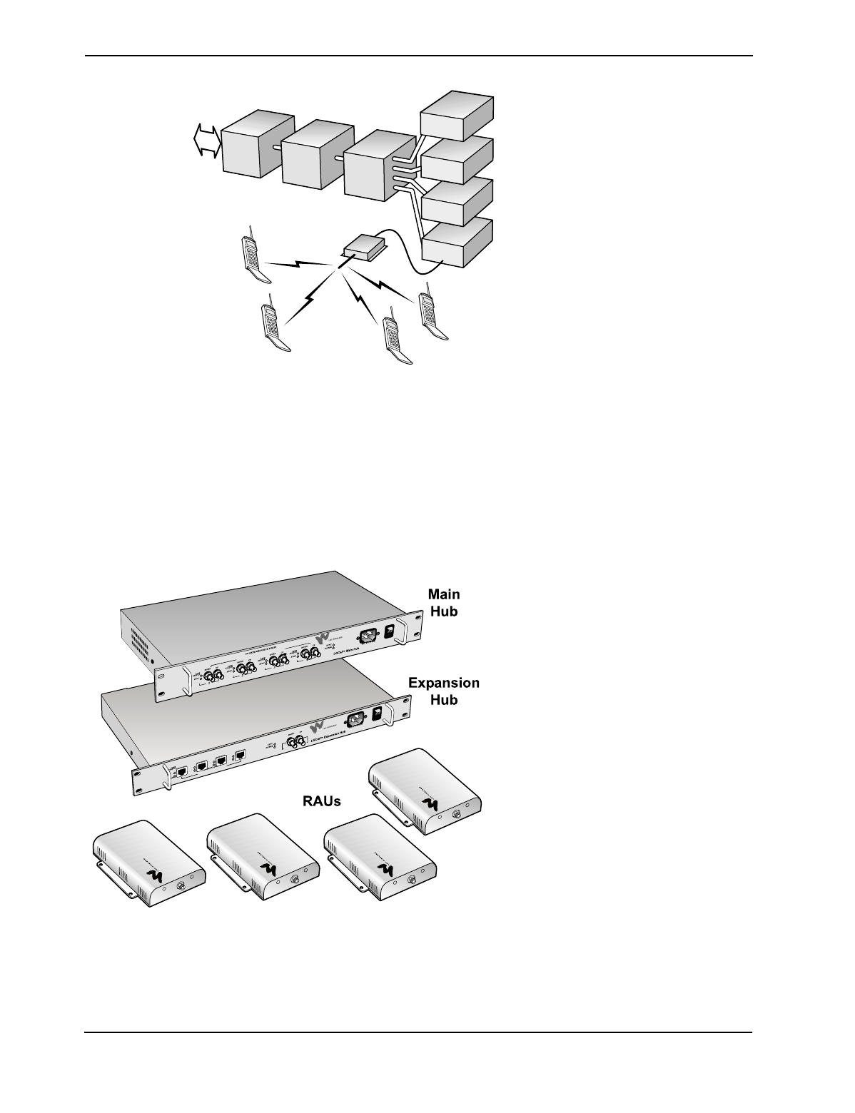
Double-Star Topology for Easy, Cost-Effective Growth
The LGCell system uses a double-star topology, which allows for easy, cost-
effective growth of coverage and/or capacity. Each Main Hub supports up to four
Expansion Hubs. Each Expansion Hub, in turn, supports up to four RAUs.
The Main Hub is located in an equipment closet and the Expansion Hubs are
distributed out into other equipment closets throughout a building. The RAUs are
then distributed off each Expansion Hub to provide coverage.
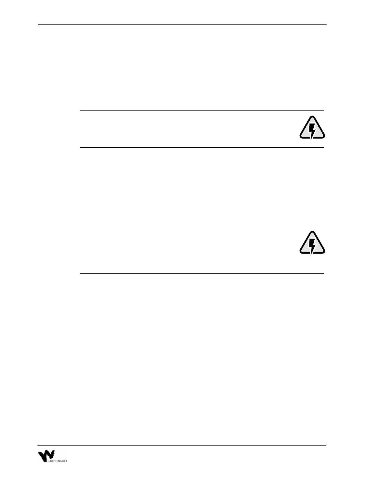
Bringing Outside In – Increases Wireless Network Coverage
Outdoor macrocellular base stations (BTSs) transmit and receive Radio Frequency
(RF) signals, which enable communications with wireless phones. The RF signals
are not always available or adequate inside a building, campus, tunnel, subway, or
other hard-to-reach location. The LGCell system delivers high-quality wireless
Multi-Mode Fiber (MMF)
Roof-
001
LGCell
Existing
Outdoor
Base Station
Mounted
Antenna
Category 5 UTP/STP
In-Building
Antenna
Repeater
1-4 About LGCell
communications when a user is within range of an LGCell Remote Antenna Unit
(RAU).
LGCell Increases In-Building Coverage
LGCell operates in the cellular or PCS frequency bands and can act as an extension
to the cellular or PCS network.
LGCell extends RF signal
coverage in places where the
coverage is unacceptable.
This extended coverage allows
users to roam between buildings
and the outside world while
maintaining wireless phone
conversations without changing
phones.
LGCell provides coverage for a
variety of applications including
single and multiple floor buildings,
campus environments, tunnels,
subways, and public facilities.
LGCell can be connected to a separate repeater for a power boost or when line of
sight is poor.
•Increase In-Building Coverage with Multiple LGCells
Use multiple LGCell systems to increase coverage in very tall buildings or large
facilities.
•Increase Coverage for Separate Service Providers
Use one or more LGCell systems for cellular networks and use one or more for
PCS networks.
•Increase Coverage for Separate Networks
Use one or more LGCell system for public networks and use one or more for
private networks.
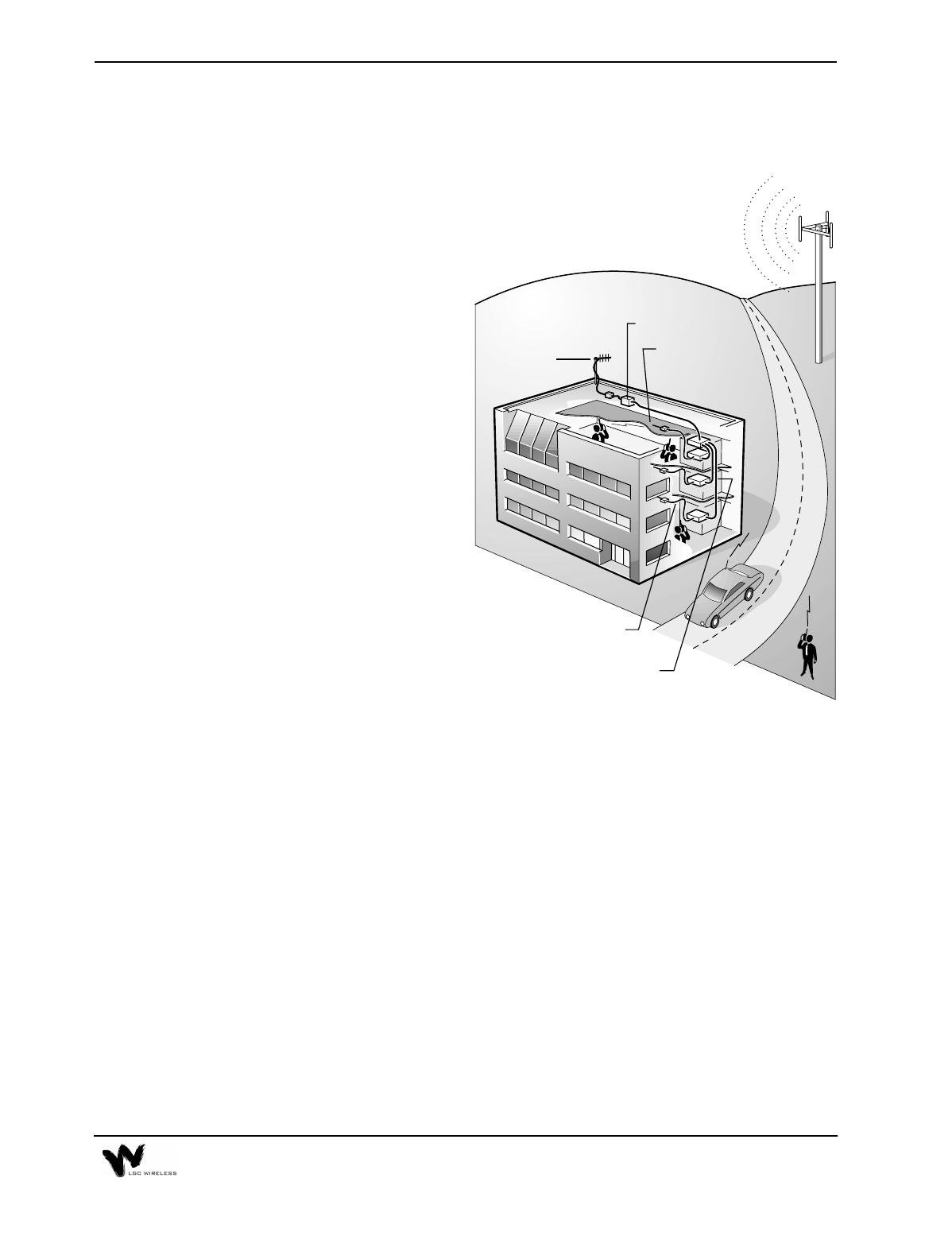
Expanding Inside – Increases In-Building Capacity and Capability
Increased in-building wireless coverage from the outdoor wireless networks does
not always fully address in-building needs. Coverage is only beneficial if all
potential users can access the network.
b002
Roof-Mounted Antenna
Repeater
Wiring
Closet
MH
EH
RAU
1-5
Microcellular Base Station (MBS) for Increased Capacity
Connecting the LGCell to a local, centralized MBS provides additional capacity, as
well as enhanced coverage.
This in-building microcellular wireless
network increases the number of in-
building users able to communicate
through their wireless phones.
•LGCell provides coverage
•MBS provides voice channel capacity
•Protocol independent
•Calls can be charged at a flat rate
versus cellular or PCS rate inside the
building
•Provides completely uniform radio
coverage at low cost
•MBS capacity is dynamically
allocated as needed
•Maintenance and control of the wireless network are centralized
The LGCell/MBS connection allocates capacity to various locations within the
enterprise as user traffic patterns change over the course of a day.
Integration Modules for Dynamic Allocation of Radio Capacity
LGC Wireless provides Integration Modules that can be used with the LGCell to
efficiently centralize additional radio capacity inside a facility. These Modules
provide the connection between the radios for the facility and the LGCell system.
Because the Integration Modules distribute all available capacity automatically
throughout all antennas within a cell, available capacity is dynamically allocated
throughout the entire coverage area, thus providing an improved grade of service
without the need to conduct ongoing traffic monitoring and analysis.
Specific installation information on all available Integration Modules is in the
Integration Module Installation and Reference Manual.
LGCell, MBS, PBX* for Increased Coverage, Capacity, and Functionality
Interfacing the LGCell with an MBS/PBX network gives wireless phone users PBX
functionality through their wireless phones, anytime, anywhere.
*Check with PBX manufacturer/vendor for compatibility, connection, and operation.
a010
MBS MH
EH
EH
EH
EH
RAU
1-6 About LGCell
With the LGCell/MBS/PBX
solution, employees can use a
wireless phone in place of a wireline
desk phone to access the PBX while
inside the building and use the same
phone for wireless communications
while outside the building. The
MBS private wireless network
transmits RF signals indoors, and
the macrocellular network takes
over outdoors.
• Access PBX features such as
four-digit dialing, call delivery,
call forwarding, call-waiting,
conferencing, and voice mail
•Billed at discounted local calling rates or a flat enterprise rate for calls made
inside the LGCell vicinity
•Users can maintain the same telephone number inside and outside of the
building, enabling anytime, anywhere communication
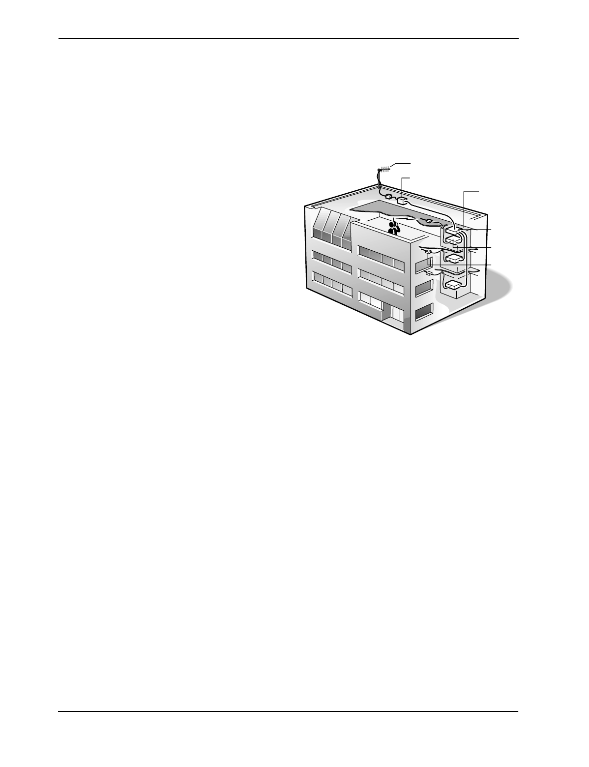
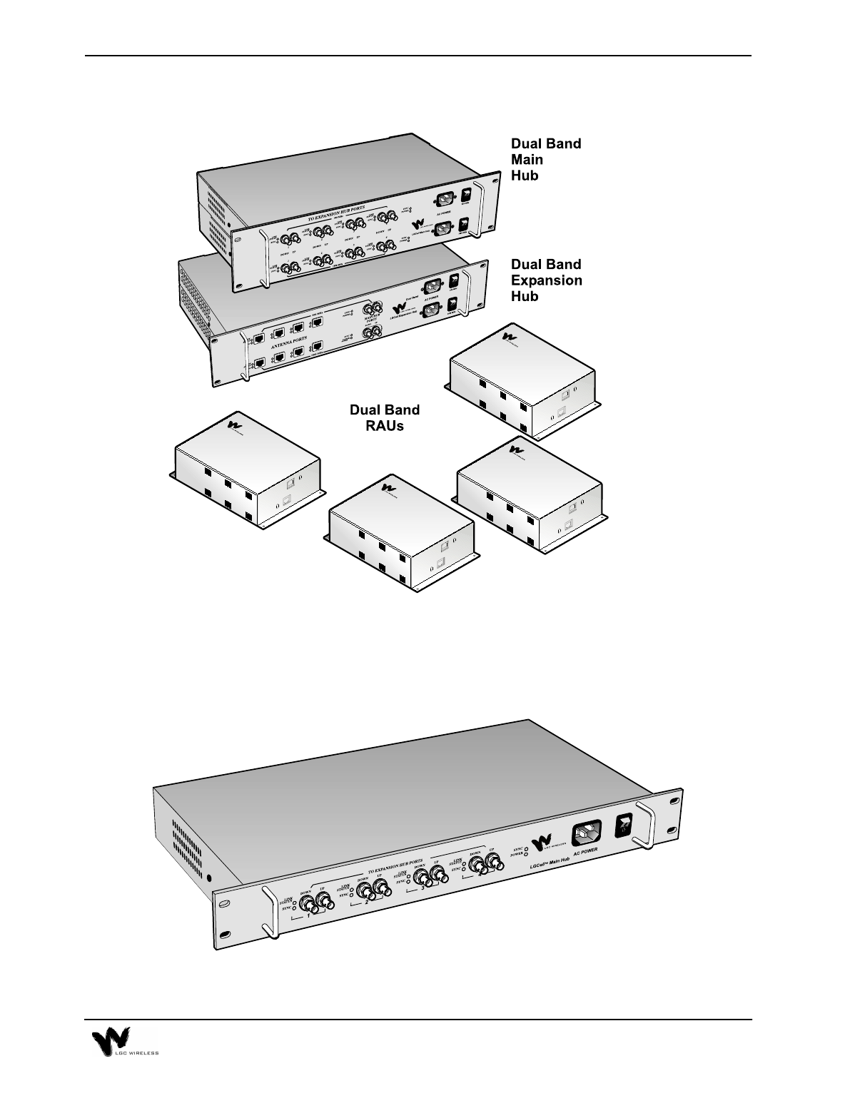
LGCell Equipment
One fully equipped LGCell system
consists of the following parts:
• One Main Hub
• Up to four Expansion Hubs
• Up to 16 RAUs (four per
Expansion Hub)
Multiple LGCell systems can be
stacked for various applications. (See
Section 5, Connectivity.)
A Dual Band LGCell system has two Main Hubs and at least two Expansion Hubs.
A Dual Band system is a combination of single bands. The following illustration
shows a Dual Band 900/1800 LGCell system.
a011
PBX MBS MH
EH
EH
EH
EH
RAU
1-7
Dual Band LGCell System
The following sections provide a brief overview of LGCell equipment. For a
detailed description of the equipment, see Section 2, LGCell Equipment.
The Main Hub
1-8 About LGCell
The Main Hub mounts into a standard 19" equipment rack commonly found in
wiring closets or equipment rooms (Main Hub width is 17.25”, or 438 mm).
•Interfaces to the wireless network
•Height is 1.7" (44.5 mm)
•Connects to a roof-mounted antenna, repeater, or MBS via standard coaxial
cable or low-loss coaxial cable with N-type male connectors
Dual Band Main Hub
The Main Hub for a Dual Band LGCell system is a pair of Main Hubs, one for each
band.
The Expansion Hub
1-9
The Expansion Hub also mounts into a standard 19" equipment rack (width 17.25”,
or 438 mm).
•Height is 1.7" (44.5 mm)
•Connects to the Main Hub via standard Multi-Mode Fiber (MMF) cable (up to
1.5 dB optical loss, approximately 1 kilometer without jumpers).
•Hubs can be located in wiring closets anywhere in the building
Dual Band Expansion Hub
An Expansion Hub for a Dual Band LGCell system is a pair of Expansion Hubs,
one for each band.
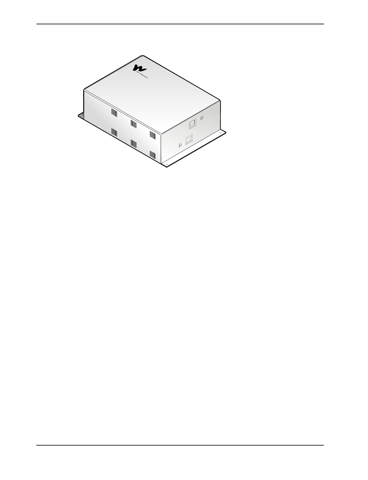
The Remote Antenna Unit (RAU)
The RAUs a re strategically positioned in and
around a building to provide high-quality
reception for wireless services.
•Connects to the Expansion Hubs via
standard CAT 5 (or better) unshielded or
shielded twisted pair (UTP/STP) cable (up
to 60 meters) (TIA/EIA 568-A standard)
•Mounts onto a variety of building materials.
Can be placed anywhere – above or below the ceiling, on the wall, or in other
locations.
•Connects to any external antenna, dipole, directional, omnidirectional, panel,
or other antenna
1-10 About LGCell
Dual Band RAU
The RAU for a Dual Band LGCell system is a pair of RAUs, one for each band.
How LGCell Works
LGCell connects in an Ethernet, LAN-like architecture, using a double-star
topology. It uses proprietary technology to provide wireless access within
buildings, subways, tunnels and other locations where reception is poor.
System Operation
System operation for all of the LGCell DAS products is identical. The only
differences between the products are the operating frequency range, access scheme
(TDMA, GSM, etc.) and certain operating parameters (gain, etc.).
The Main Hub connects to an RF source:
•a roof-mounted antenna or repeater for coverage applications; or
•an MBS for capacity or wireless PBX applications, or both.
LGCell distributes cellular and PCS signals through standard MMF and standard
UTP/STP cable found in most buildings. This allows installation of in-building
wireless services with minimal installation time and cost.

1-11
Transmit/Forward/Downlink (BTS to Phone)
The incoming RF signal into the Main Hub is split into several fiber optic
transceivers that convert the RF signal to an optical signal. The Main Hub transmits
the converted signal over the fiber to the Expansion Hub. The Expansion Hub
converts the optical signal to an RF signal and transmits the RF signals to the RAUs.
The RAUs then transmit the RF signals to the antenna and then to wireless phones.
Receive/Reverse/Uplink (Phone to BTS)
The RAUs transmit RF signals from wireless phones back through the antenna and
to the Expansion Hubs. The Expansion Hubs transmit the RF signals back to the
Main Hub in optical form. The Main hub converts the optical signals back to
electrical signals and sends them to an MBS, a repeater, or a roof-mounted antenna.
For a detailed description of system operation, see Section 2, LGCell Equipment.
LGCell Advantages
The LGCell solution is based on a fundamentally new approach that has cost and
engineering advantages not found in competitive systems.
Competitive systems offer similar capabilities but require sophisticated RF
engineering and take a long time to install. They typically use specialty cables that
require expensive, difficult, time-consuming, and potentially disruptive
installations.
LGCell’s plug-and-play design requires minimal RF engineering and planning. Its
unique double-star architecture keeps service and maintenance to a minimum,
unlike cascaded antenna systems. The flexible architecture permits deployment in
the most difficult RF environments.
LGCell’s low cost and simple installation effectively provide both coverage and
capacity enhancements to meet the demands of the growing wireless network.

1-12 About LGCell
LGCell Uses Industry Standards
LGCell’s use of industry standards and standard equipment offers high reliability
and low cost.
•Complies with industry standards for IS-19-B/AMPS, J-std-8, IS-136/TDMA,
IS-95/CDMA, ETSI 300 609-4/GSM (CE marked), and iDEN.
•Utilizes the TIA/EIA 568-A Ethernet cabling standards for ease of installation
(see Appendix A – Cables, Connectors, and Accessories).
•Distributes signals over a building’s existing industry-standard cable
infrastructure of MMF and UTP/STP cable.
•Complies with UL and FCC or CE mark requirements.
•Primarily constructed with highly reliable industry-standard components
produced in high-volume for the LAN and wireless industries. High quality
and reliability are assured.
Minimal Design, Installation, Maintenance, and Troubleshooting
•Site engineering is simplified since compensation for cable loss and amplifiers
do not need to be designed into the system, which saves precious RF
Engineering time and support.
•Using standard cabling reduces installation to simple equipment mounting and
cable connection.
•Centralized hub locations facilitate maintenance, upgrades, and adaptability to
new standards.
•The LGCell’s star configuration eases troubleshooting – it is immediately clear
if an RAU is faulty.
•LGCell provides full Operations Alarm Maintenance and Provisioning
(OAM&P). The Main Hub senses major alarms through contact closure. These
alarms can be sent to remote locations. (For information on the Alarm Report
Monitor, see Appendix E – Alarm Report Monitor (ARM2000).)
What You Need to Do
Assess the installation site, prepare the site, install the LGCell equipment, install
and connectorize the cables, and mount the Hubs and RAUs. A typical installation
consists of three components:
•Site Planning See Section 3, LGCell Site Planning and Design
•Cable Installation See Section 3, LGCell Site Planning and Design
•LGCell Installation See Section 4, LGCell Installation
2LGCell Equipment
This section describes the LGCell equipment and explains how the system operates
and contains LGCell system specifications.
For details about cables and connectors, refer to Appendix A – Cables, Connectors,
and Accessories.
LGCell has no user-serviceable parts. Faulty or failed units may be
repaired or replaced through LGC Wireless. In the U.S., please contact us
at 1-800-530-9960. International customers, please contact us at
+1-408-487-2400.
Contents
LGCell Equipment
Standard Equipment. . . . . . . . . . . . . . . . . . . . . . . . . . . . . . . . . . . . . . . . . . . . . . . . 3
Main Hub . . . . . . . . . . . . . . . . . . . . . . . . . . . . . . . . . . . . . . . . . . . . . . . . . . . . . . . . 3
Expansion Hub. . . . . . . . . . . . . . . . . . . . . . . . . . . . . . . . . . . . . . . . . . . . . . . . . . . 10
Remote Antenna Unit (RAU) . . . . . . . . . . . . . . . . . . . . . . . . . . . . . . . . . . . . . . . 13
LGCell System Specifications. . . . . . . . . . . . . . . . . . . . . . . . . . . . . . . . . . . . . . . 16
Band Selective Option . . . . . . . . . . . . . . . . . . . . . . . . . . . . . . . . . . . . . . . . . . . . . 20

2-2 LGCell Equipment
2-3
Standard Equipment
The LGCell standard equipment supports 800 MHz AMPS/TDMA/CDMA/iDEN,
900 MHz GSM, 1800 MHz DCS, 1800 MHz Korean PCS, 1900 MHz TDMA/
CDMA/GSM, and Dual Band 900 GSM/1800 DCS installations.
LGCell has three modular components:
•Main Hub – 19” rack-mountable
•Expansion Hub – 19” rack-mountable
•Remote Antenna Units (RAUs) – Wall or ceiling mountable
LGCell is shipped with the following items:
•Four rack-mount screws per hub
•Four screws for each RAU
•LGCell Installation and Reference Manual
For cable and accessory information, see Appendix A – Cables,
Connectors, and Accessories.
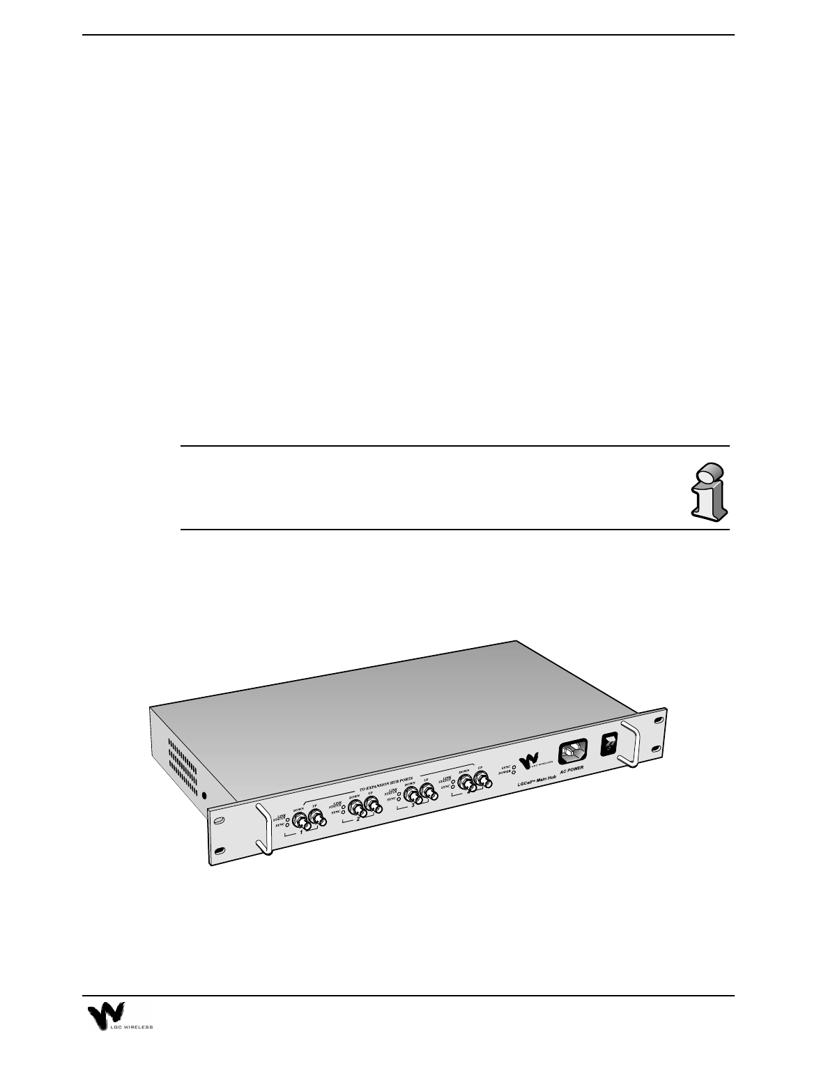
Main Hub
The Main Hub is the LGCell’s central distribution point. It receives downlink
cellular or PCS signals from an MBS or a roof-mounted antenna and redistributes
them to multiple Expansion Hubs in low-frequency signal format (<200MHz),
which can be passed over the MMF and CAT 5 cabling.
2-4 LGCell Equipment
The Main Hub also receives signals from the Expansion Hubs and reconverts them
back to the cellular or PCS band for transmission on the uplink channel (mobile) to
the macrocellular base station (BTS) or microcellular base station (MBS).
The Dual Band 900/1800 Main Hub is shown below.
Main Hub Features
•Mounts in a standard 19” equipment rack, width 17.25” (438 mm)
•Height is 1.7” (44.5 mm). The Dual Band Main Hub is 3.5” (88.9 mm) high.
•Operates with worldwide AC power, 100-240 VAC at 1.6 A and 50/60 Hz
•Connects up to four Expansion Hubs and 16 RAUs per Main Hub. The Dual
Band Main Hub connects up to four Expansion Hubs and 16 RAUs for the 900
system and an equal number for the 1800 system.
•Connect multiple Main Hubs to increase number of RAUs. See “Connecting
Multiple LGCell Systems” on page 3 in Section 5, Connectivity.
•Connects to a roof-mounted antenna, repeater, or duplexed MBS via one
coaxial cable using an N-type, female, duplexed, bi-directional RF connector
•Connects to MBS via two coaxial cables using two N-type female, simplex RF
connectors
•Connects to Expansion Hubs via MMF fiber cable (up to 1 kilometer)
•Distributes cellular or PCS signals to the Expansion Hubs via standard MMF
transmit and receive pairs
•Has easily accessible connectors
2-5
•Displays system status via front panel LEDs
•Provides contact closure of major alarms and error latches through a D-sub
9-pin connector
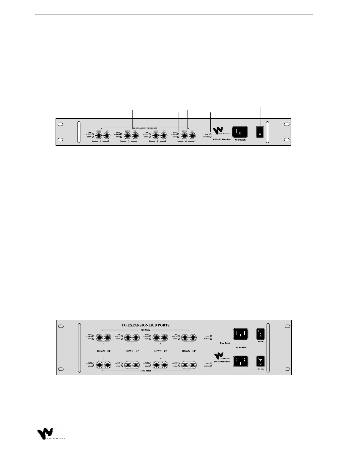
Main Hub Front Panel
Front Panel Description
1AC power cord connector
2Power On/Off switch
3One LED for sync status (labeled SYNC)
4One LED for power (labeled POWER)
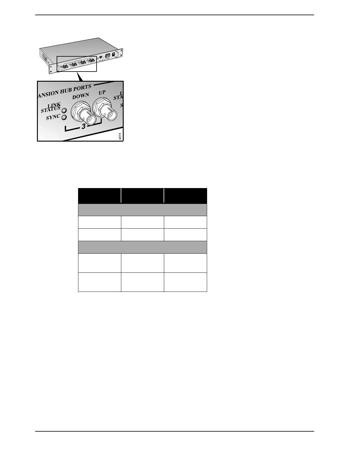
5Four Ports (labeled 1, 2, 3, 4)
•One standard female ST-connector for MMF downlink (labeled DOWN)
•One standard female ST-connector for MMF uplink (labeled UP)
6One LED for port RF link status (labeled LINK STATUS)
7One LED for port sync status (labeled SYNC)
The Dual Band Main Hub Front Panel is shown below. The connectors are the same
as those explained for the single band system.
12
3
4
55 5 5 6
7
2-6 LGCell Equipment
Standard MMF Uplink and Downlink Ports
The Main Hub transmits and receives RF signals to and from
the Expansion Hubs using up to 1 kilometer of industry-
standard 62.5µm/125µm MMF cable (up to 1.5 dB optical loss,
approximately 1 kilometer without jumpers).
•Uplink/Input (labeled UP)
This signal is the combination of all uplink signals received
by the Expansion Hubs connected to the system.
•Downlink/Output (labeled DOWN)
The downlink is a composite signal coming from the
duplexed N-type connector or from the downlink simplex
connector on the Main Hub back panel. The downlink signal
is re-radiated at all RAUs.
Main Hub LEDs
LED Color Indication
HUB LEDS
POWER Green On/Off Fault
SYNC Green On/Off Fault
PORT LEDS
SYNC Green
Red Operational
Fault
LINK STATUS Green
Red Operational
Fault
2-7
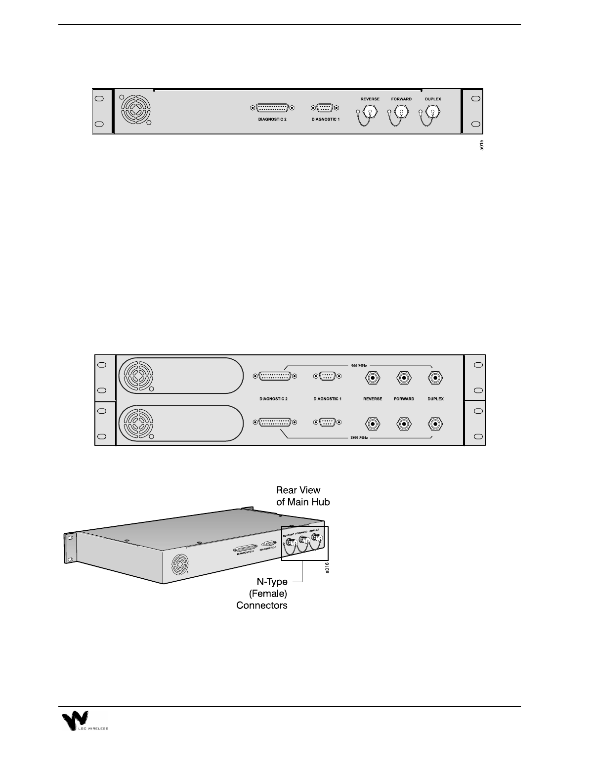
Main Hub Back Panel
Back Panel Description
•Three N-type, Female Connectors with dust caps
•One Duplexed (labeled DUPLEX)
•One Uplink (labeled REVERSE)
•One Downlink (labeled FORWARD)
•One D-Sub 9-pin Connector (labeled DIAGNOSTIC 1)
•One D-sub 25-pin Connector (labeled DIAGNOSTIC 2)
The Dual Band Main Hub Back Panel is shown below. The connectors are the same
as shown for the single band LGCell Main Hub.
N-Type Female Connectors
The N-type, female connectors
connect the coaxial cable from the
roof-mounted antenna, repeater, or
MBS to the Main Hub for RF
connection. These cable connectors
are operational in the cellular and PCS
frequency bands.
See Maximum Input RF Power per
Carrier vs. Number of Carriers, on page 17 in this section for the maximum uplink
and downlink power.
2-8 LGCell Equipment
There are three N-type female connectors:
Duplexed: Output and Input (bi-directional)
Uplink: Simplex Output (unidirectional)
Downlink: Simplex Input (unidirectional)
•Duplexed (labeled DUPLEX)
The DUPLEX connector is for a duplexed
connection. This connector provides both
downlink and uplink signals to and from the
roof-mounted antenna, repeater, or MBS to the
Main Hub. This duplex port provides a 30 or 40
dB gain on the duplex part. See “LGCell
System Gain” on page 17.
•Uplink (labeled REVERSE) and
Downlink (labeled FORWARD)
The uplink and downlink connectors are for a
simplex connection. The FORWARD connector
receives RF signals and the REVERSE connector
transmits RF signals to and from the roof-
mounted antenna, repeater, or MBS.
DO NOT exceed the maximum input power into the Main Hub. See
Maximum Input RF Power per Carrier vs. Number of Carriers, on page
17 in this section.
2-9
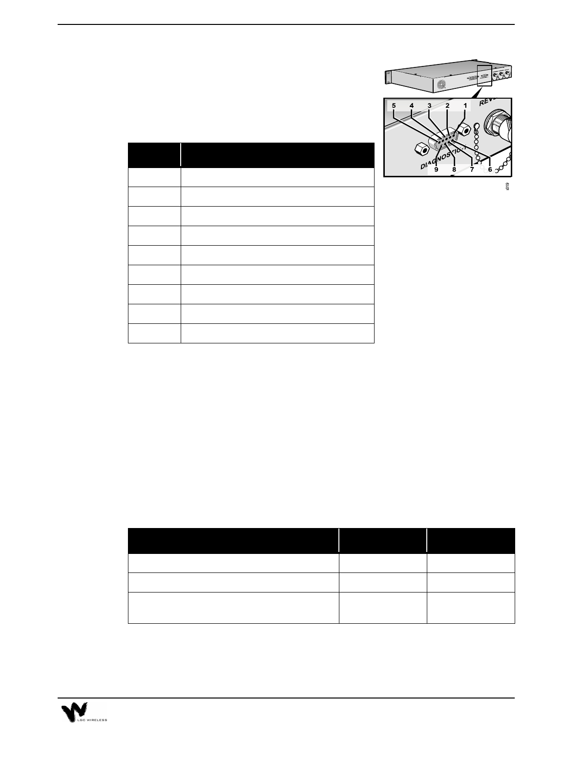
D-Sub 9-Pin Connector
The D-Sub 9-pin connector (labeled DIAGNOSTIC 1)
provides contact closure for major and latch system
alarm monitoring. The following table lists the
function of each pin on the D-sub 9-pin connector.
Alarms
LGCell provides full Operations Alarm Maintenance and Provisioning (OAM&P).
The Main Hub senses then latches major alarms. An error latch provides historical
information for troubleshooting.
The major alarms and error latches are monitored with contact closures. Alarms can
be sent to remote locations (see Section 5, Connectivity and Section 6,
Troubleshooting). For details about alarm monitoring, see Appendix E – Alarm
Report Monitor (ARM2000).
The two error connections, Major Error and Error Latch, are relay connections.
They are either open or short circuit (see the following table).
When you use these error pin connections, determine the error status by sending a
current of no more than 40 mA through the positive connection and returning it
through the negative connection. An error is indicated if current ceases to flow
through the error connection.
Pin Function
1+10 V (fused)
2 Not connected
3 Not connected
4 Error Latch (positive connection)
5 Error Latch (negative connection)
6 DC Ground
7 Major Error (positive connection)
8Error Reset
9 Major Error (negative connection)
Operation Major Error Error Latch
Proper Operation Short Circuit Short Circuit
Error Open Circuit Open Circuit
Proper Operation but had error and system latched;
alarm was not reset Short Circuit Open Circuit
2-10 LGCell Equipment
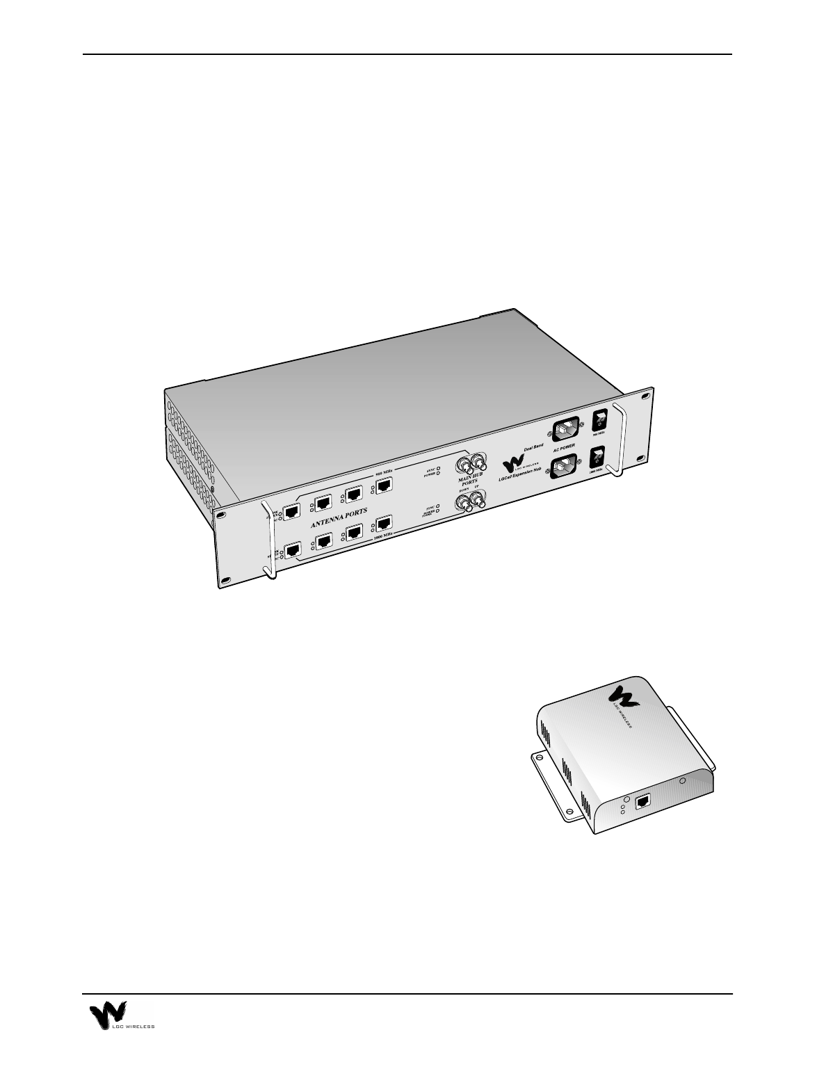
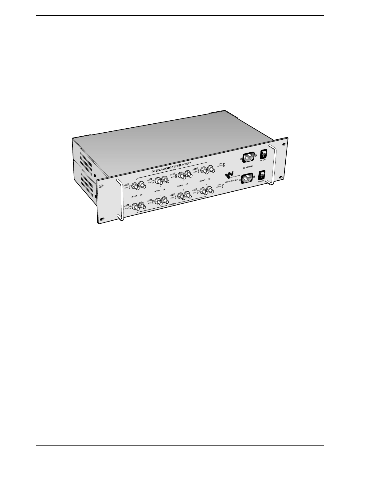
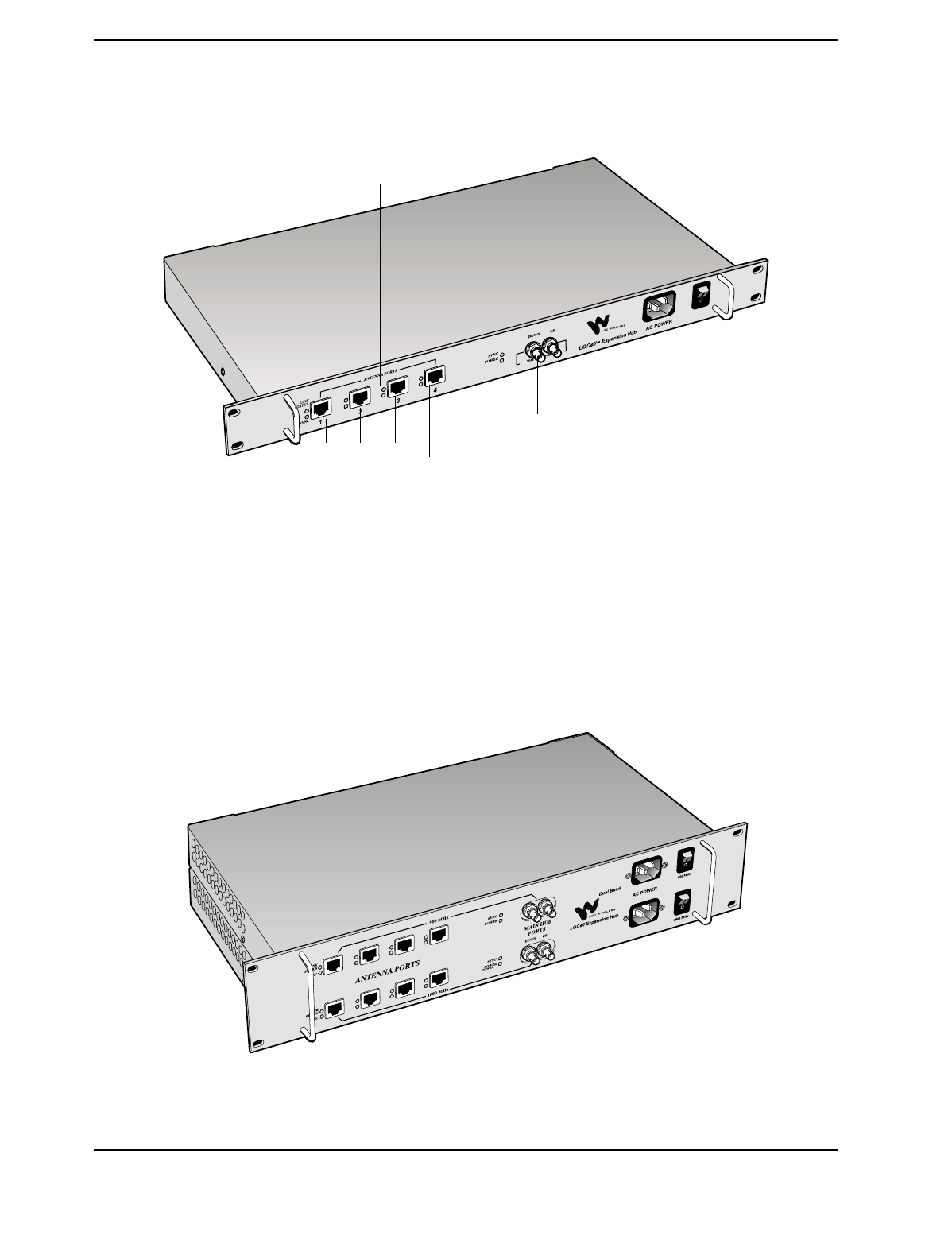
Expansion Hub
The Expansion Hub is LGCell’s intermediate distribution point.
It transmits and receives low frequency signal (<200MHz) to and from the Main
Hub, and to and from the RAUs. Utilizing LGC Wireless’ proprietary technology,
both the MMF and the UTP/STP cables can transmit signals in the cellular or PCS
frequency bands.
The Dual Band 900/1800 Expansion Hub is shown below:
Antenna Ports
Main Hub Port
1234
2-11
Expansion Hub Features
•Mounts in a standard 19" equipment rack, with 17.25” (438 mm)
•Height is 1.7" (44.5 mm). The Dual Band Expansion Hub is 3.5” (88.9 mm)
high.
•Operates with worldwide AC power, 100-240 VAC at 1.6 A and 50/60 Hz
•Connects up to four RAUs. The Dual Band Expansion Hub connects up to four
RAUs for the 900 system and up to four RAUs for the 1800 system.
•Connects to the Main Hub with MMF transmit/receive cable (up to 1.5 dB
optical loss, approximately 1 kilometer without jumpers)
•Connects up to four RAUs via four RJ-45 connectors that feed RAUs directly
through a UTP/STP cable
•Provides DC power to RAUs through the UTP/STP cable
•Has easily accessible connectors
•Displays system operation via front panel LEDs
•Communicates with Main Hub for system alarm status
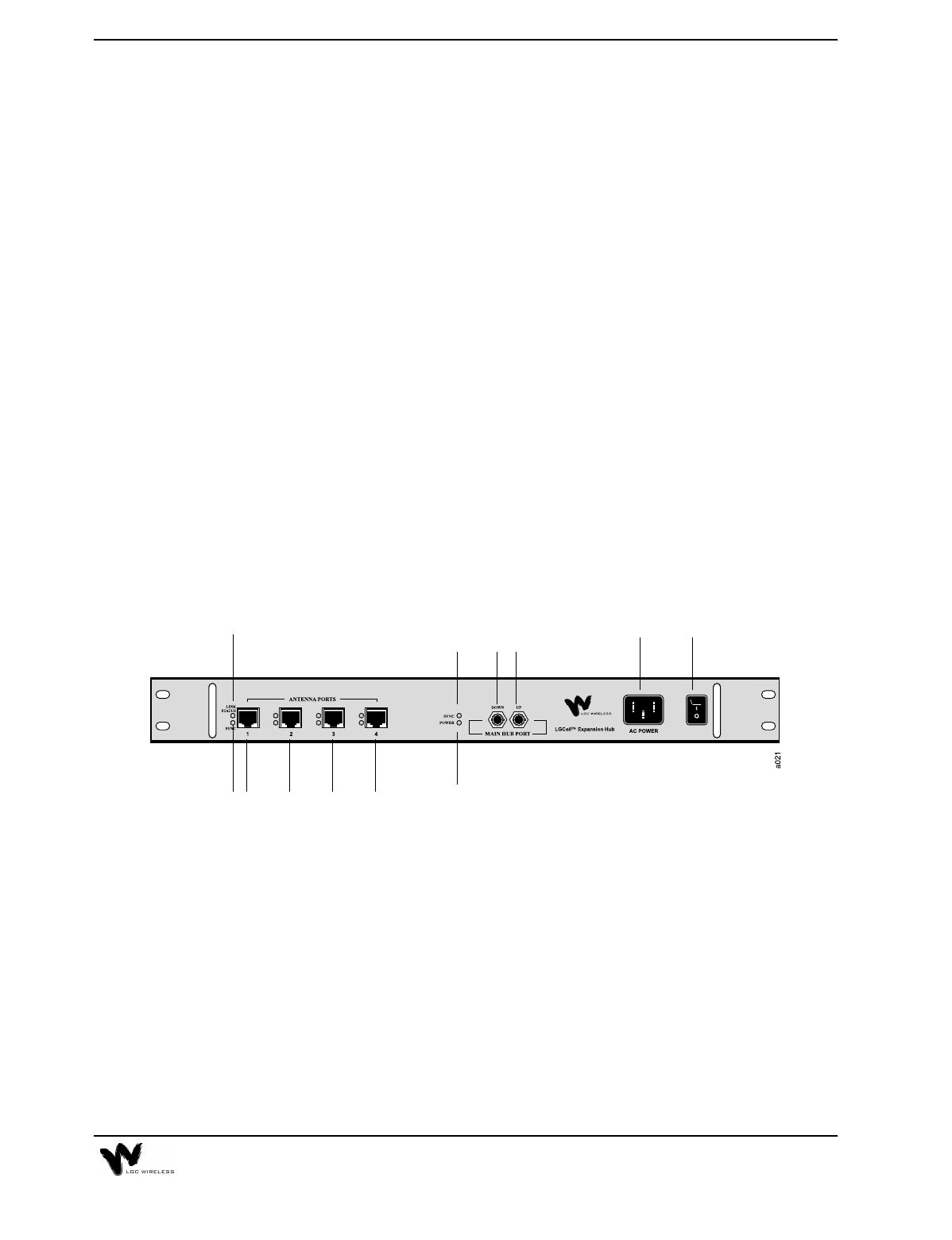
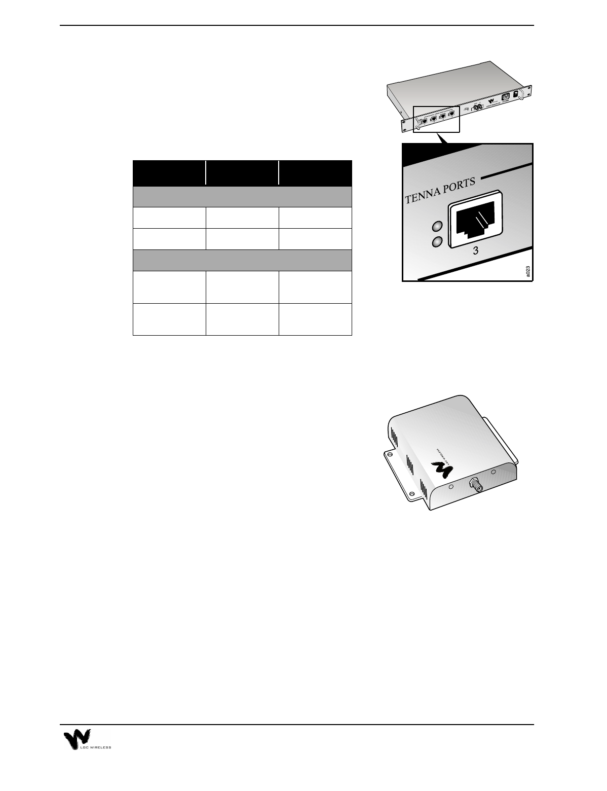
Expansion Hub Front Panel
Expansion Hub Description
1AC power cord connector
2Power On/Off switch
3In Fiber Port (labeled MAIN HUB), one standard ST connector for MMF
downlink (labeled DOWN)
4In Fiber Port (labeled MAIN HUB), one standard ST connector for MMF uplink
(labeled UP)
5One LED for port sync status (labeled SYNC)
6One LED for power (labeled POWER)
7Four standard UTP/STP CAT 5 Cable RJ-45 female connectors (labeled
ANTENNA PORTS 1, 2, 3, and 4)
1 2
35
6
7
4
777
(Labeled 1, 2, 3, and 4)
9
8
2-12 LGCell Equipment
8One LED to monitor RF link status (labeled LINK STATUS)
9One LED to monitor sync status (labeled SYNC)
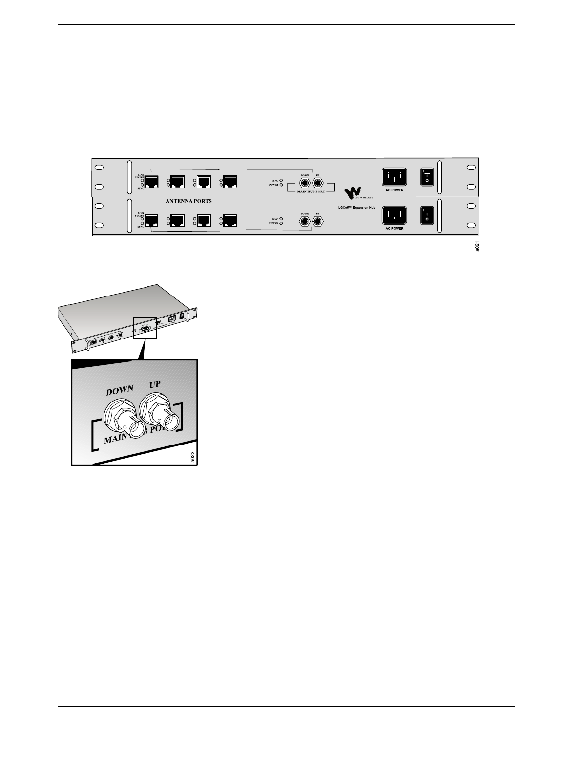
The Dual Band Expansion Hub Front Panel is shown below. The connectors are the
same as those explained for the single band system.
Standard MMF Uplink and Downlink Port
The Expansion Hub transmits and receives cellular or PCS signals
to and from the Main Hub using up to 1 kilometer of industry-
standard 62.5µm/125 µm MMF cable found in most buildings.
•Uplink/Output (labeled UP)
The uplink is the combination of all uplink signals received by the
RAUs. The signals are fed into the Expansion Hub via the UTP/STP
cables. The Expansion Hub then transmits the combination of all
signals to the Main Hub via the MMF cable.
•Downlink/Input (labeled DOWN)
The Expansion Hub receives downlink signals from the Main Hub
via the other MMF port. The downlink signals are subsequently re-
radiated at all RAUs via the UTP/STP cable.
DUAL BAND
900 MHz
1800 MHz
2-13
UTP/STP CAT 5 Cable Connectors
Delivers electrical power to the RAUs. Also
transmits downlink signals and receives uplink
signals to and from the RAUs.
Expansion Hub LEDs
Remote Antenna Unit (RAU)
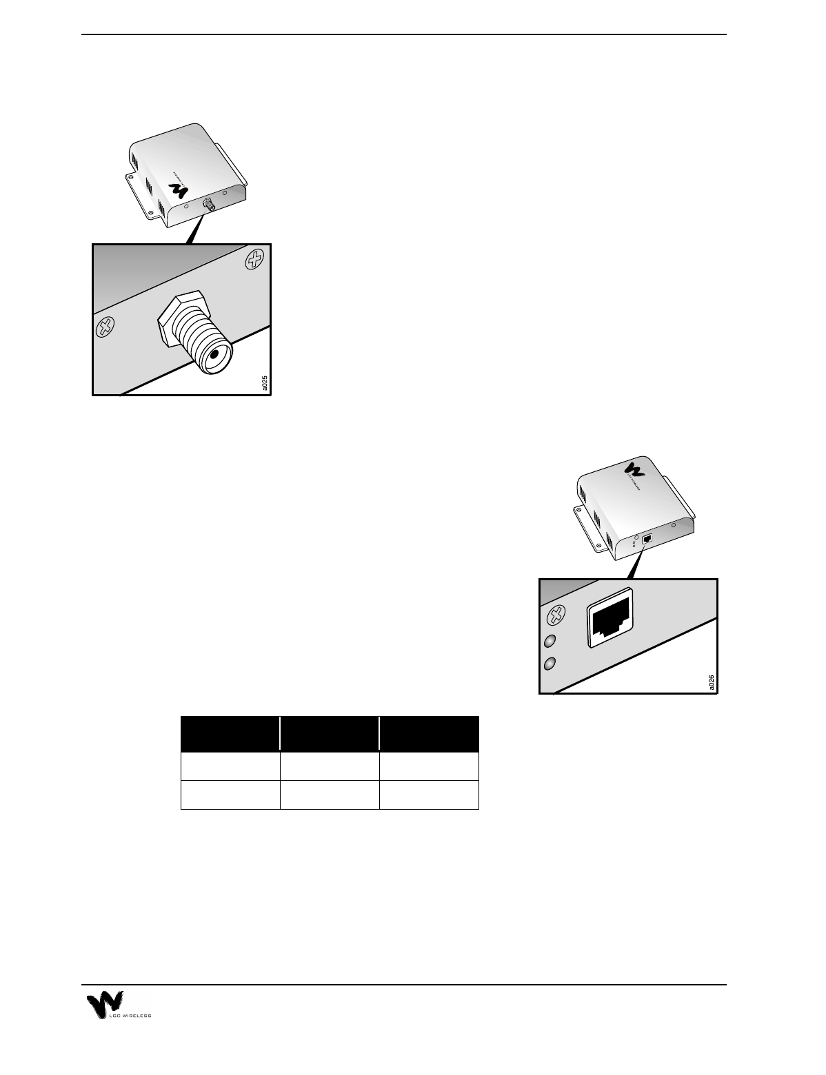
RAU Description
•One female SMA connector
•One Standard CAT 5 UTP/STP RJ-45
female receptacle
•Two LEDs
•One for antenna power
•One for antenna sync indication
LED Color Indication
HUB LEDS
POWER Green On/Off Fault
SYNC Green On/Off Fault
PORT LEDS
SYNC Green
Red Operational
Fault
LINK STATUS Green
Red Operational
Fault
2-14 LGCell Equipment
The Dual Band 900/1800 RAU is shown here. The Dual Band RAU has the same
connectors as the single band RAU. It has one set of connectors for the 900 RAU
and one set for the 1800 RAU.
RAUs are active antennas that connect directly to an Expansion Hub over standard
CAT 5 (or better) UTP/STP cable. The cable also delivers electrical power to the
antenna.
RAUs receive uplink cellular or PCS signals and re-transmits them to an Expansion
Hub in a low frequency signal format (<200MHz).
They also receive signals from the Expansion Hub, and re-convert the signals back
to the cellular or PCS band for transmission on the downlink.
RAU Features
•Transmits to Expansion Hubs via an RJ-45 connector using UTP/STP cable
•Uses an SMA connector for standard in-building antennas
•Has easily accessible connectors
•Displays system operation via LEDs
•Dimensions: 5.7" x 5.5" x 1.2" (145 mm x 140 mm x 30 mm). The dimensions
for the Dual Band RAU are 8” x 6.2” x 2.7” (1626 mm x 157 mm x 69 mm).
•Connects to Expansion Hub via one RJ-45 connector that feeds RAUs directly
through a UTP/STP cable (up to 60 meters)
For system performance for cable lengths greater than 60 meters, see “LGCell
System Gain vs. UTP/STP Cable Length (800 MHz, iDEN, 900 MHz)” on page 6
and “LGCell System Gain vs. UTP/STP Cable Length for 1800 MHz or 1900 MHz
(Horizontal run, measured with 1 km of Multi-Mode Fiber)” on page 7 in
Appendix A – Cables, Connectors, and Accessories.
2-15
RAU Connectors
SMA Connector
The SMA connector on the RAU is a duplexed RF input/output
port that connects to standard in-building antennas.
•Uplink (Input)
The uplink cellular or PCS channels are received from the
mobile phone by the in-building antenna. For the maximum
downlink composite radiated power at the RAU, see the table
on page 17 in this chapter.
•Downlink (Output)
The downlink channels are transmitted (radiated) by the
standard in-building antenna. For the maximum downlink
composite radiated power at the RAU, see the table on page 17
in this chapter.
Standard CAT 5 UTP/STP RJ-45 Jack
Delivers electrical power to the antenna. Also
transmits and receives uplink and downlink signals
to the Expansion Hub.
RAU LEDs
If the antenna SYNC LED lights red, RF power in the antenna is automatically shut
down. The antenna RF power is reset when the SYNC LED goes off.
LED Color Indication
POWER Green On
SYNC Red Fault
2-16 LGCell Equipment
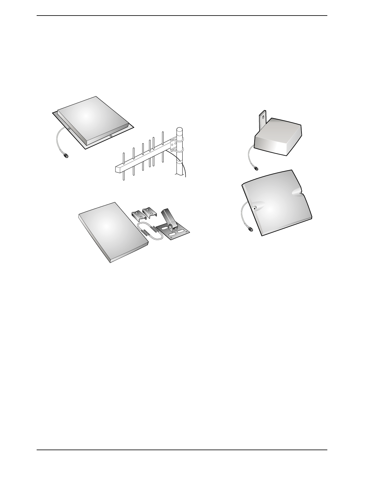
RAU Optional Antennas
The following illustration shows optional antennas that can plug into the SMA
connector. For recommended antennas, refer to the accessory section in the LGCell
Price List or contact your account manager.
LGCell System Specifications
The following tables give system specifications for LGCell.
•System gain, maximum input/output RF Power
•Maximum Input Power per Carrier vs. Number of Carriers
2-17
LGCell System Gain
This table is a summary of the system gain for different frequencies and formats.
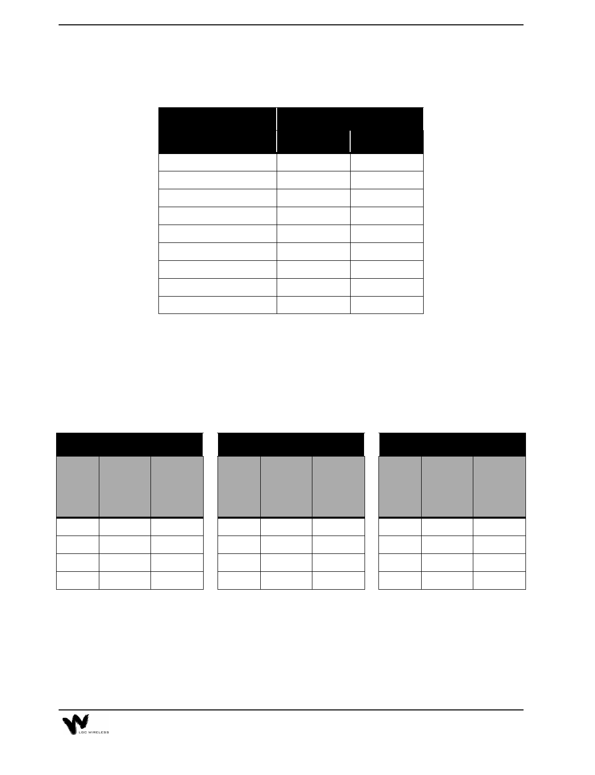
Maximum Input RF Power per Carrier vs. Number of Carriers
When you connect a Main Hub to an MBS that supports several RF carriers, the RF
power per carrier must be cut back so as not to exceed the total composite radiated
power into the Main Hub DUPLEX or FORWARD connector. The following table
shows the maximum power per carrier and maximum composite power for different
frequencies, formats, and numbers of carriers.
LGCell
Frequency/Format
System Gain
Duplex Simplex
800 MHz AMPS, TDMA 30 0
800 MHz CDMA 30 0
800 MHz iDEN 0 0
900 MHz GSM 0 0
1800 MHz CDMA 0 0
DCS 1800 GSM 0 0
1900 MHz TDMA 40 0
1900 MHz CDMA 40 0
1900 MHz GSM 40 0
800 CDMA 1800 Korean CDMA 1900 TDMA
Number
of
Carriers
Maximum
Power
per
Carrier
Maximum
Composite
Power
Number
of
Carriers
Maximum
Power
per
Carrier
Maximum
Composite
Power
Number
of
Carriers
Maximum
Power
per
Carrier
Maximum
Composite
Power
1 10.0 10.0 1 9.0 9.0 1 10.0 10.0
2 7.0 10.0 2 6.0 9.0 2 7.0 10.0
3 5.2 10.0 3 4.2 9.0 3 5.2 10.0
4 3.0 9.0 4 2.0 8.0 4 3.0 9.0
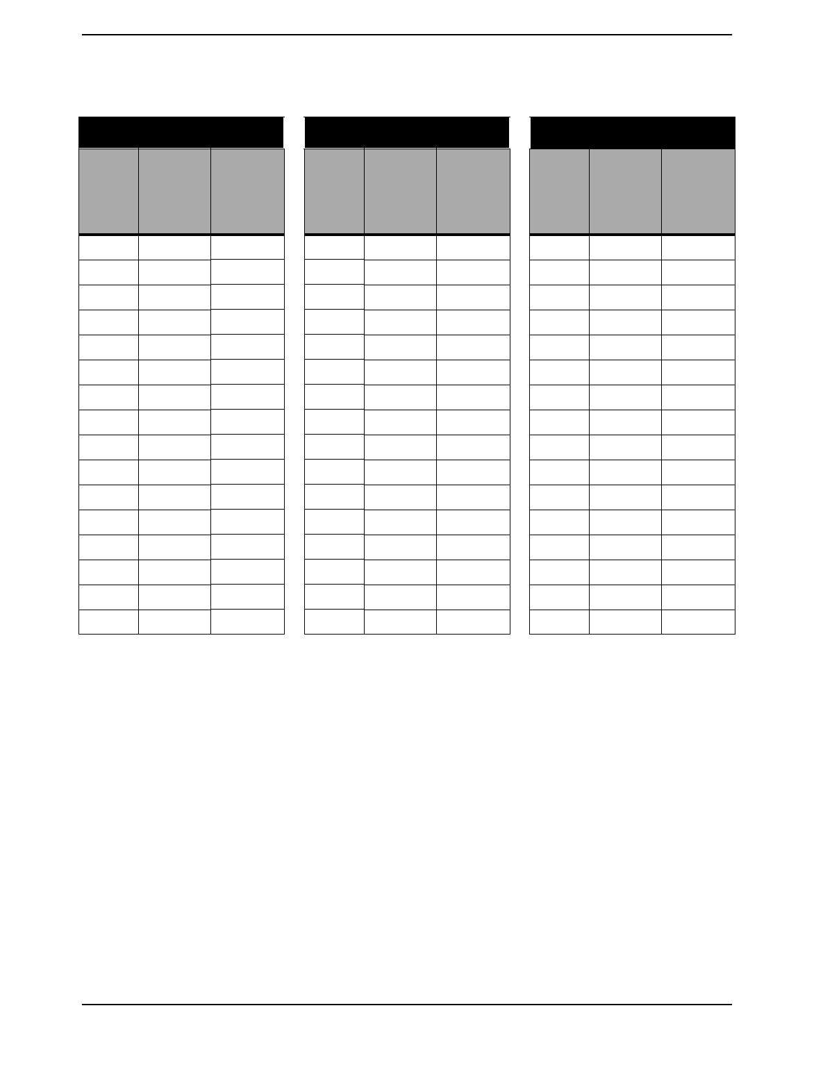
2-18 LGCell Equipment
800 AMPS 800 TDMA 800 GSM
Number
of
Carriers
Maximum
Power
per
Carrier
Maximum
Composite
Power
Number
of
Carriers
Maximum
Power
per
Carrier
Maximum
Composite
Power
Number
of
Carriers
Maximum
Power
per
Carrier
Maximum
Composite
Power
1 20.0 20.0 1 17.0 17.0 1 20.0 20.0
2 15.5 18.5 2 12.5 15.5 2 8.0 11.0
3 12.8 17.6 3 9.8 14.6 3 6.0 10.8
4 11.0 17.0 4 8.0 14.0 4 4.7 10.7
5 9.5 16.5 5 6.5 13.5 5 3.8 10.8
6 8.3 16.1 6 5.3 13.1 6 3.0 10.8
7 7.3 15.8 7 4.3 12.8 7 2.3 10.8
8 6.5 15.5 8 3.5 12.5 8 2.0 11.0
9 5.7 15.2 9 2.7 12.2 9 1.5 11.0
10 5.0 15.0 10 2.0 12.0 10 1.2 11.2
11 4.4 14.8 11 1.4 11.8 11 0.8 11.2
12 3.8 14.6 12 0.8 11.6 12 0.5 11.3
13 3.3 14.4 13 0.3 11.4 13 0.3 11.4
14 2.8 14.3 14 -0.2 11.3 14 0.0 11.5
15 2.4 14.1 15 -0.6 11.1 15 -0.1 11.7
16 1.9 14.0 16 -1.1 11.0 16 -0.3 11.7
2-19
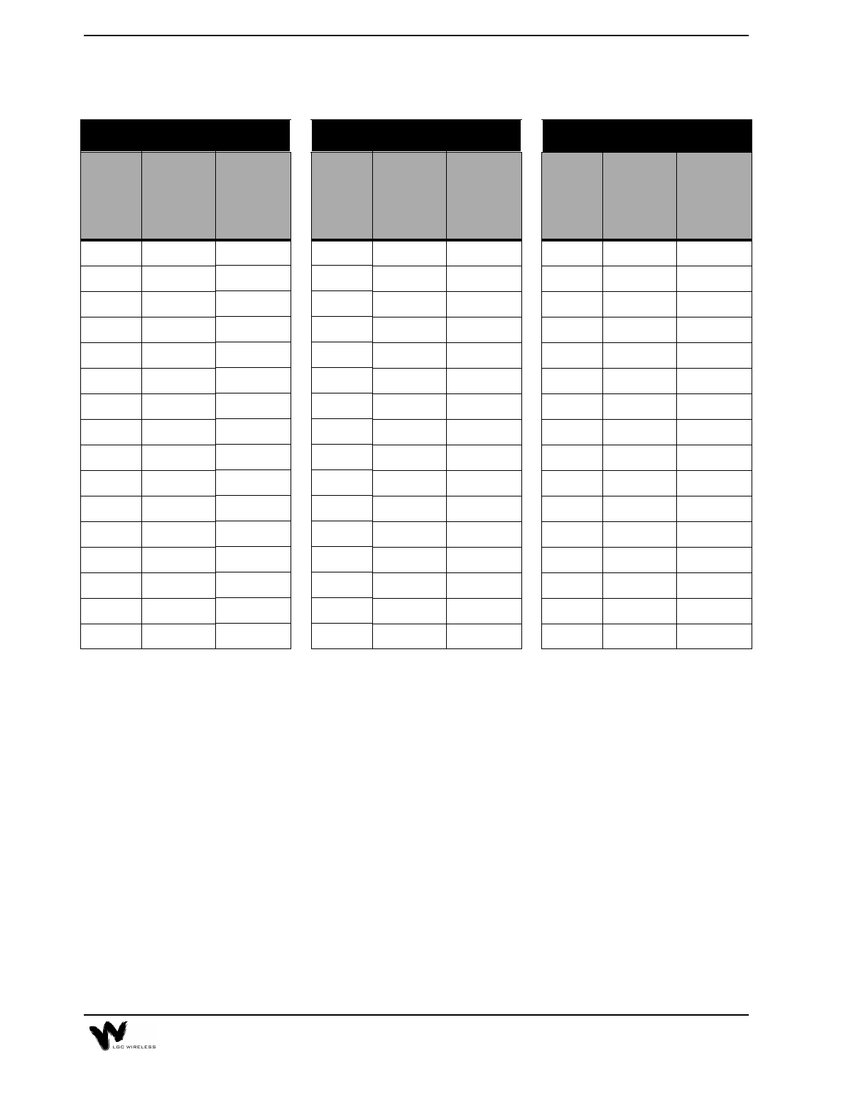
1800 DCS/GSM 1900 AMPS 1900 TDMA
Number
of
Carriers
Maximum
Power
per
Carrier
Maximum
Composite
Power
Number
of
Carriers
Maximum
Power
per
Carrier
Maximum
Composite
Power
Number
of
Carriers
Maximum
Power
per
Carrier
Maximum
Composite
Power
1 18.0 18.0 1 20.0 20.0 1 17.0 17.0
2 6.0 9.0 2 13.5 16.5 2 12.5 15.5
3 4.0 8.8 3 11.5 16.3 3 9.8 14.6
4 2.7 8.7 4 10.3 16.3 4 8.0 14.0
5 1.8 8.8 5 9.3 16.3 5 6.5 13.5
6 1.0 8.8 6 8.3 16.1 6 5.3 13.1
7 0.3 8.8 7 7.3 15.8 7 4.3 12.8
8 0.0 9.0 8 6.5 15.5 8 3.5 12.5
9 -0.4 9.1 9 5.7 15.2 9 2.7 12.2
10 -0.8 9.2 10 5.0 15.0 10 2.0 12.0
11 -1.1 9.3 11 4.4 14.8 11 1.4 11.8
12 -1.4 9.4 12 3.8 14.6 12 0.8 11.6
13 -1.7 9.4 13 3.3 14.4 13 0.3 11.4
14 -1.9 9.6 14 2.8 14.3 14 -0.2 11.3
15 -2.1 9.7 15 2.4 14.1 15 -0.6 11.1
16 -2.3 9.7 16 1.9 14.0 16 -1.1 11.0
2-20 LGCell Equipment
Band Selective Option
LGCell 800 MHz, 900 MHz, 1800 MHz, and 1900 MHz
The LGCell 800/900 MHz system has fixed bands of operation. The LGCell 1800/
1900 MHZ system has a fixed bandwidth filter in each system that is centered over
the desired band of operation. The desired band of operation is an ordered item
either by band (A, B, D, E, F) or by the center uplink and downlink frequency.
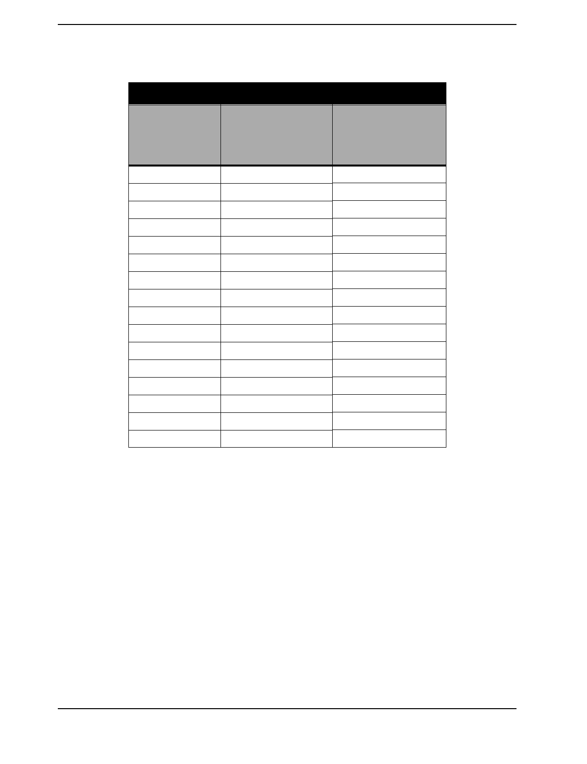
1900 GSM
Number
of
Carriers
Maximum
Power
per
Carrier
Maximum
Composite
Power
1 20.0 20.0
2 8.0 11.0
3 6.0 10.8
4 4.7 10.7
5 3.8 10.8
6 3.0 10.8
7 2.3 10.8
8 2.0 11.0
9 1.5 11.0
10 1.2 11.2
11 0.8 11.2
12 0.5 11.3
13 0.3 11.4
14 0.0 11.5
15 -0.1 11.7
16 -0.3 11.7
2-21
The following table shows the bandwidths for each type of system.
For example, the A band for 1900 MHz PCS has the fixed 15 MHz filter centered
at 1937.5 MHz for the downlink and 1857.5 for the uplink.
1 30 MHz pass filter can be positioned along the 75 MHz DCS 1800 band. Order product with uplink and
downlink frequency at 1.25 MHz spacing. For example an uplink center frequency of 1737.5 MHz will provide
a 30 MHz band between 1722.5 MHz and 1752.5 MHz and a downlink center frequency of 1832.5 MHz will
provide a 30 MHz band between 1817.5 MHz and 1847.5 MHz.
2 Similar to above, the 1900 PCS 15 MHz filter can be positioned along the 60 MHz band.
The LGCell covers a 30 MHz band in frequency range of 1710 MHz to 1785 MHz
on the uplink and 1805 MHz to 1880 MHz on the downlink. The operator can
choose where to place the 30 MHz band of operation by choosing the corresponding
center frequencies as shown in the following table.
System Fixed Filter
Bandwidth Uplink Center
Frequency Downlink Center
Frequency
DAS 800 MHz - AMPS,
TDMA, CDMA
25 MHz 836.5 MHz 881.5 MHz
DAS 800 MHz - iDEN 18 MHz 815 MHz 860 MHz
DAS 900 GSM 25 MHz 947.5 MHz 902.5 MHz
DAS 1800 KOREAN CDMA 30 Mhz 1765 MHz 1855 MHz
DAS 1800 DCS (GSM) 30 MHz 1725 MHz1 to 1770
MHz 1820 MHz1 to 1865
MHz
DAS 1900 MHz - CDMA,
TDMA, GSM
15 MHz 1857.5 MHz2 to
1892.5 MHz 1937.5 MHz2 to
1972.5 MHz
2-22 LGCell Equipment
Band Center Frequency of the DCS 1800 MHz LGCell
The filter band is 30 MHz wide (or 15 MHz on each side of the center).
The following table shows settings for the 1900 MHz system.
Settings for Selecting Band Center Frequency of the 1900 MHz
LGCell System
Uplink Freq Downlink Freq Uplink Freq Downlink Freq
1725.00 1820.00 1748.75 1843.75
1726.25 1821.25 1750.00 1845.00
1727.50 1822.50 1751.25 1846.25
1728.75 1823.75 1752.50 1847.50
1730.00 1825.00 1753.75 1848.75
1731.25 1826.25 1755.00 1850.00
1732.50 1827.50 1756.25 1851.25
1733.75 1828.75 1757.50 1852.50
1735.00 1830.00 1758.75 1853.75
1736.25 1831.25 1760.00 1855.00
1737.50 1832.50 1761.25 1856.25
1738.75 1833.75 1762.50 1857.50
1740.00 1835.00 1763.75 1858.75
1741.25 1836.25 1765.00 1860.00
1742.50 1837.50 1766.25 1861.25
1743.75 1838.75 1767.50 1862.50
1745.00 1840.00 1768.75 1863.75
1746.25 1841.25 1770.00 1865.00
1747.50 1842.50
Band Uplink Frequency Downlink Frequency
A1857.50 1937.50 MHz
D1867.50 1947.50 MHz
B 1877.50 1957.50 MHz
E 1887.50 1967.50 MHz
F 1892.50 1972.50 MHz

3LGCell Site Planning and Design
This section provides information to assist in planning and designing an LGCell
system and preparing a site for the LGCell installation. Proper project management
is instrumental in providing a timely and accurate deployment.
The first step in planning an LGCell system is to estimate the amount of radio
frequency (RF) coverage you need for your building or coverage area. Initial
estimates can be developed using floor plans and the models that follow. Eventually
you need to go on-site to evaluate the facility’s readiness for installation and
possibly perform RF measurements in order to guarantee performance. The LGC
Wireless Site Survey Questionnaire is included for your reference.
Contents
LGCell Site Planning and Design
Project Management . . . . . . . . . . . . . . . . . . . . . . . . . . . . . . . . . . . . . . . . . . . . . . . 3
RF Coverage Estimate for a Site . . . . . . . . . . . . . . . . . . . . . . . . . . . . . . . . . . . . . . 4
RF Measurements and Site Survey . . . . . . . . . . . . . . . . . . . . . . . . . . . . . . . . . . . . 7
Site Survey Questionnaire . . . . . . . . . . . . . . . . . . . . . . . . . . . . . . . . . . . . . . . . . . . 7

3-2 LGCell Site Planning and Design

3-3
Project Management
Installing the LGCell system is easy after all of the pre-installation requirements are
met. It is beneficial to have one person manage and coordinate all aspects of the
planning, design, and installation. Managing the process should avoid unnecessary
surprises.
The project manager is the person responsible for assigning tasks and ensuring
scheduled work is performed on time. This includes collecting all information
necessary for a complete site assessment, getting cost estimates and purchase order
(PO) approval, scheduling any cabling work, scheduling the LGCell installation
and commissioning, and providing final as-built documentation.
The project manager also acts as the coordinator between the following people:
Cellular or PCS carrier
RF engineer
Site acquisition person
MBS vendor
MBS installer
Cabling contractor(s)
End user
If you do not have a designated project manager, please contact LGC Wireless. We
can provide you with an estimate of what it would cost to have LGC Wireless
manage your project. Please call us at 1-800-530-9960 (in the U.S.). International
customers, please call us at +1-408-487-2400.
3-4 LGCell Site Planning and Design
Project Management Estimated Timeline
RF Coverage Estimate for a Site
To provide adequate RF coverage within a facility, you need a median signal level
strong enough for good voice communications.
As a guideline, you can refer to the following tables for general coverage areas,
based on a design goal of 0 dBm output power per carrier, -85 dBm received signal
strength (independent of communications protocol), 5 dB fade margin and 3 dBi
antenna gain.
Description Details Time Interval
Detailed site walk-
through/RF survey Prepare installation information, including RF plan,
floor plan, equipment order form, and final design. 2 weeks
Order LGCell
equipment Get all standard parts and accessories required. 8 weeks
Select cabling
contractor Complete installation statement of work and provide
floor plan with equipment locations, list of cabling
runs, and other materials and connections. Get
cabling quotation after walk-through.
2 weeks
Order all other
equipment Get equipment from all vendors, including cables,
connectors, MBS, surge protectors, and so on.
Monitor order progress and shipment.
4 weeks
Install cable Monitor installation. 1-5 days
Install LGCell Review installation checklist and prepare all
materials. 1-3 days
Test installation and
RF coverage Be sure there are no blank areas. 1 hour per
RAU
Generate as-built
document Prepare site plan diagram and coverage performance. 1-5 days
3-5
Antenna Coverage for 800/900 MHz Frequency Applications (0 dBm
per carrier, 5 dB fade margin, -85 dBm design goal and 3 dBi antenna
gain)
Antenna Coverage for 1800/1900 MHz Frequency Applications
Office Antenna Coverage for 800/900 MHz Frequency Applications
Facility PLS Coverage per Antenna (Square Feet)
Manufacturing 27.3 30,000
Hospital 28.8 15,000
Airport 27.3 30,000
Retail 27.7 25,000
Warehouse 27.3 30,000
Parking Garage 26.8 40,000
Facility PLS Coverage per Antenna (Square Feet)
Manufacturing 24.9 25,000
Hospital 26.5 10,000
Airport 24.9 25,000
Retail 25.2 20,000
Warehouse 24.9 25,000
Parking Garage 24.3 35,000
Facility PLS Coverage per Antenna (Square Feet)
Open - 80% cubicles/20% offices 27.7 25,000
80% - 50% cubicles/50% offices 28.2 20,000
10% - 20% cubicles/80% offices 28.8 15,000
3-6 LGCell Site Planning and Design
Office Antenna Coverage for 1800/1900 MHz Frequency Applications
The preceding tables show estimated clutter-defined path loss slope (PLS)
for different frequencies at various kinds of sites. If you change the design
goal or other parameters, these numbers will change based on the PLS.
If the design parameters (output power per carrier, design goal, antenna gain, and
fade margin) differ from those stated above, you can use the PLS value shown in
the preceding tables in the following formula to estimate the area of coverage per
antenna:
The PLS is a general path loss number which takes into account free space
loss and normal barriers to the RF signal. Severe obstructions such as
metal, cement walls, or elevator shafts are best accounted for by a physical
site survey.
Facility PLS Coverage per Antenna (Square Feet)
Open - 80% cubicles/20% offices 25.2 20,000
80% - 50% cubicles/50% offices 25.7 15,000
10% - 20% cubicles/80% offices 26.5 10,000
Path Loss Formulas
Path Loss (dB) = PLS * log 4πfD / c
Note: Path Loss Slope = PLS dB/decade for free space loss
D is the distance in meters
f is the frequency in MHz
c is the speed of light
Path Loss=Power per Carrier + Antenna Gain - Fade Margin - Design Goal (dBm)
To convert feet to meters:
Area = (D x 3.281)2 x π
D = [10(Path Loss / PLS)] x [c / (4πf)]
3-7
As a reference the following table gives estimates of the signal loss for some RF
barriers.
Average Signal Loss of Common Building Materials
RF Measurements and Site Survey
Before designing an LGCell system, one should go to the site and measure the loss
characteristics of the building. To determine the amount of coverage per antenna,
the best method is a test of RF propagation, which you can do on-site with a test
transmitter and field strength meter.
While at the site, one can use the following Site Survey Questionnaire to document
site specifics.
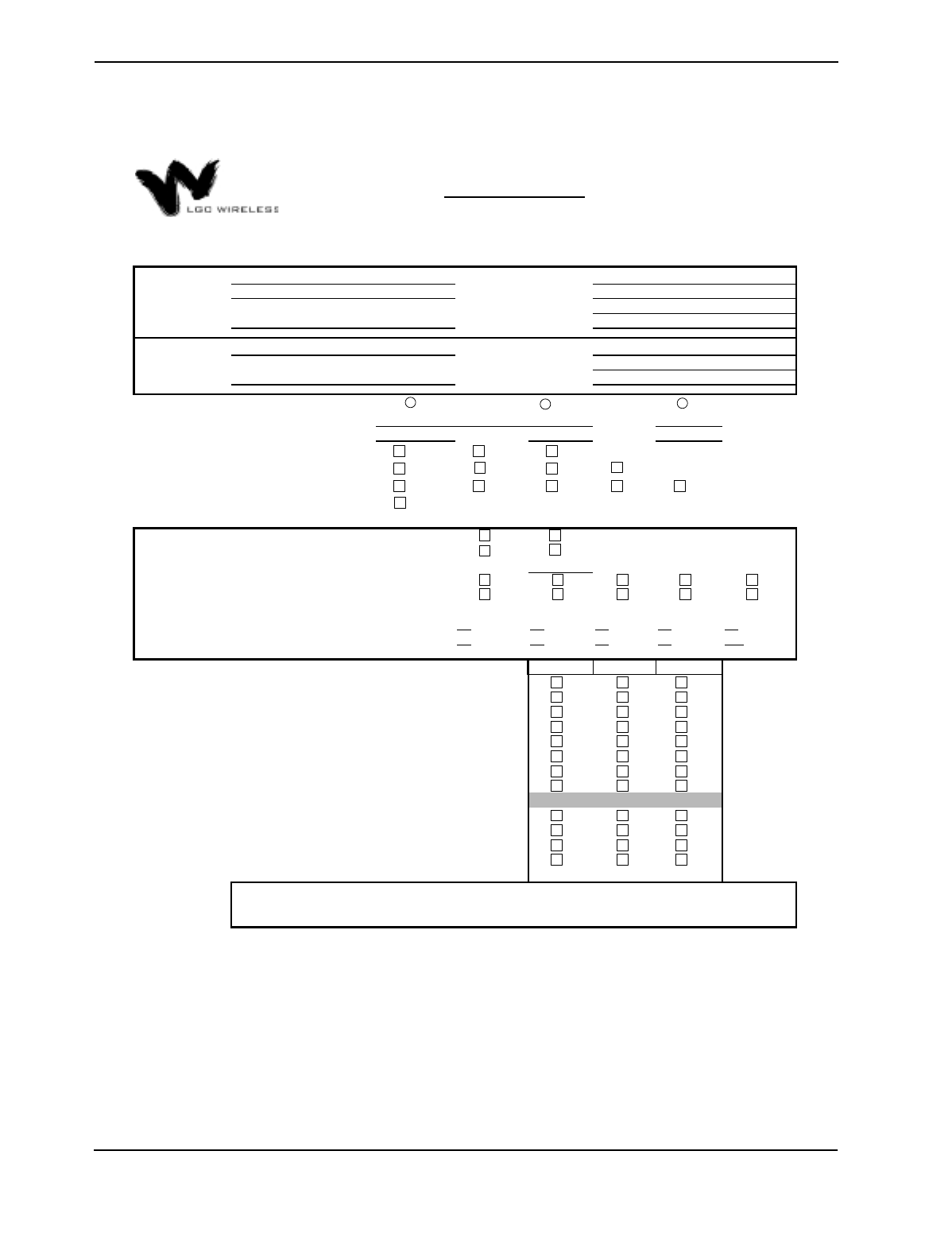
Site Survey Questionnaire
You can use the LGC Wireless Site Survey Questionnaire to help design your
LGCell system. A sample questionnaire follows. The following information is
needed when you walk a site:
Partition Type Loss @ 815 MHz
Metal wall 26 dB
Aluminum siding 20 dB
Concrete block wall 13 dB
Foil insulation 4 dB
Concrete floor 15 dB
Sheetrock 1.4 dB
3-8 LGCell Site Planning and Design
585 EAST BROKAW ROAD | SAN JOSE, CA 95112 | TEL 408.487.2400 | FAX 408.487.2410
End-User Contact:
# of Carriers:
BHCR: Erlangs/Sub:
1 = 2 = 3 = 4 = 5 =
6 = 7 = 8 = 9 = 10 =
Yes No Don't Know
Locations for Main & Expansion Hubs Available (closets):
Estimated Installation Start Date (Must Provide If Services are Needed):
Type of System Enhancement:
If BTS, what Manufacturer & Model #:
If BTS, what is the # of Subscribers:
What is the desired downlink power at mobile (dBm):
Are Exposed Antennas Tolerated Inside:
Are Floor Plans Available (Including Map Scale):
Site Survey Questionaire
Address:
Address:
Phone:
Company Name:
Frequency(ies):
Protocol(s):
E-Mail:
Add'l Comments:
(Special install
requirements, covered
areas
,
contacts
,
e
t
If so, which Services:
- Project Management:
Are 19" Equipment Racks Available:
Is AC Power available at the Main and Expansion Hubs:
Are Multimode Fiber Optic Cables Already Available:
- Site Survey:
- LGCell Equipment Install & Commissioning:
- CAT5, MMF, Coax & Antenna Installation:
Are CAT 5 UTP/STP Runs Already Available:
Are LGC Wireless Services Required:
Are Exposed Antennas Tolerated Outside:
Is Coverage Required Out Doors:
If Floor Plans are not available, how many Buildings are to be Covered:
How Many Floors per Building:
(Use the Add'l comments if needed)
Total Square Footage to Cover per Building:
(Use the Add'l comments if needed)
Project Name:
End-User:
Purchaser: Contact:
Phone:
E-Mail:
YES
YES NO
NO
Coverage (BDA) Capacity (BTS) Wireless Office
1 2 3 4 5
6 7 8 9 10
-75 -80 -85
800 900 1800 1900
GSM TDMA CDMA
DCS
AMPS iDEN
CONFIDENTIAL AND PROPRIETARY
Not to be distributed without prior written consent of LGC Wireless
Ver. 2.0