ADC Telecommunications DLCSMR3D Digivance LRCS SMR Dual Band System User Manual 75179
ADC Telecommunications Inc Digivance LRCS SMR Dual Band System 75179
Contents
- 1. manual1
- 2. manual2
- 3. manual3
manual1
Preliminary
ADCP-75-179
Preliminary Issue A
September 2004
1304947 Rev 1
(Digivance® LRCS 800/900 MHz SMR System
with Version 3.01 EMS Software
(Operation and Maintenance Manual
20025-A

ADCP-75-179
Preliminary Issue A
September 2004
1304947 Rev 1
Digivance® LRCS 800/900 MHz SMR System
with Version 3.01 EMS Software
Operation and Maintenance Manual

ADCP-75-179 • Preliminary Issue A • September 2004 • Preface
Page ii
COPYRIGHT
© 2004, ADC Telecommunications, Inc.
All Rights Reserved
Printed in the U.S.A.
REVISION HISTORY
LIST OF CHANGES
The technical changes incorporated into this issue are listed below.
TRADEMARK INFORMATION
ADC and Digivance are registered trademarks of ADC Telecommunications, Inc.
Stargazer is a registered trademark of ADC DSL Systems, Inc.
Procomm Plus is a registered trademark of Quarterdeck Corporation.
Acrobat and Adobe are registered trademarks of Adobe Systems, Inc.
DISCLAIMER OF LIABILITY
Contents herein are current as of the date of publication. ADC reserves the right to change the contents without prior notice. In no
event shall ADC be liable for any damages resulting from loss of data, loss of use, or loss of profits and ADC further
disclaims any and all liability for indirect, incidental, special, consequential or other similar damages. This disclaimer of
liability applies to all products, publications and services during and after the warranty period.
This publication may be verified at any time by contacting ADC’s Technical Assistance Center at 1-800-366-3891, extension 73476
(in U.S.A. or Canada) or 952-917-3476 (outside U.S.A. and Canada), or by e-mail to wireless.tac@adc.com
ISSUE DATE REASON FOR CHANGE
A 09/2004 Original issue.
PAGE IDENTIFIER DESCRIPTION OF CHANGE
All Original issue.
ADC Telecommunications, Inc.
P.O. Box 1101, Minneapolis, Minnesota 55440-1101
In U.S.A. and Canada: 1-800-366-3891
Outside U.S.A. and Canada: (952) 938-8080
Fax: (952) 917-1717

ADCP-75-179 • Preliminary Issue A • September 2004 • Preface
Page iii
© 2004, ADC Telecommunications, Inc.
TABLE OF CONTENTS
Content Page
ABOUT THIS MANUAL . . . . . . . . . . . . . . . . . . . . . . . . . . . . . . . . . . . . . . . . . . . . . . . . . . . . . . . . . . . . . . . . . . . . . . . . vii
RELATED PUBLICATIONS . . . . . . . . . . . . . . . . . . . . . . . . . . . . . . . . . . . . . . . . . . . . . . . . . . . . . . . . . . . . . . . . . . . . . . vii
ADMONISHMENTS . . . . . . . . . . . . . . . . . . . . . . . . . . . . . . . . . . . . . . . . . . . . . . . . . . . . . . . . . . . . . . . . . . . . . . . . . .viii
GENERAL SAFETY PRECAUTIONS . . . . . . . . . . . . . . . . . . . . . . . . . . . . . . . . . . . . . . . . . . . . . . . . . . . . . . . . . . . . . . . .viii
STANDARDS CERTIFICATION . . . . . . . . . . . . . . . . . . . . . . . . . . . . . . . . . . . . . . . . . . . . . . . . . . . . . . . . . . . . . . . . . . . . ix
LIST OF ACRONYMS AND ABBREVIATIONS . . . . . . . . . . . . . . . . . . . . . . . . . . . . . . . . . . . . . . . . . . . . . . . . . . . . . . . . . . . ix
SECTION 1:
OVERVIEW
1 INTRODUCTION. . . . . . . . . . . . . . . . . . . . . . . . . . . . . . . . . . . . . . . . . . . . . . . . . . . . . . . . . . . . . . . . . . . . . . . .1-1
2 LRCS SYSTEM OVERVIEW . . . . . . . . . . . . . . . . . . . . . . . . . . . . . . . . . . . . . . . . . . . . . . . . . . . . . . . . . . . . . . . .1-1
2.1 Basic System Components . . . . . . . . . . . . . . . . . . . . . . . . . . . . . . . . . . . . . . . . . . . . . . . . . . . . . . . . . .1-1
2.2 Enhanced Base Transceiver Station Interface. . . . . . . . . . . . . . . . . . . . . . . . . . . . . . . . . . . . . . . . . . . . . .1-3
2.3 Handset Interface . . . . . . . . . . . . . . . . . . . . . . . . . . . . . . . . . . . . . . . . . . . . . . . . . . . . . . . . . . . . . . . .1-3
2.4 Local Interface . . . . . . . . . . . . . . . . . . . . . . . . . . . . . . . . . . . . . . . . . . . . . . . . . . . . . . . . . . . . . . . . . .1-3
2.5 Network Operations Center Interface . . . . . . . . . . . . . . . . . . . . . . . . . . . . . . . . . . . . . . . . . . . . . . . . . . .1-5
2.6 SNMP Interface . . . . . . . . . . . . . . . . . . . . . . . . . . . . . . . . . . . . . . . . . . . . . . . . . . . . . . . . . . . . . . . . . .1-6
3 SYSTEM FUNCTIONS AND FEATURES . . . . . . . . . . . . . . . . . . . . . . . . . . . . . . . . . . . . . . . . . . . . . . . . . . . . . . . .1-7
3.1 Fiber Optic Transport . . . . . . . . . . . . . . . . . . . . . . . . . . . . . . . . . . . . . . . . . . . . . . . . . . . . . . . . . . . . . .1-7
3.2 Control and Monitoring Software . . . . . . . . . . . . . . . . . . . . . . . . . . . . . . . . . . . . . . . . . . . . . . . . . . . . . .1-9
3.3 Fault Detection and Alarm Reporting . . . . . . . . . . . . . . . . . . . . . . . . . . . . . . . . . . . . . . . . . . . . . . . . . . .1-9
3.4 Powering . . . . . . . . . . . . . . . . . . . . . . . . . . . . . . . . . . . . . . . . . . . . . . . . . . . . . . . . . . . . . . . . . . . . . .1-9
3.5 Equipment Mounting and Configuration . . . . . . . . . . . . . . . . . . . . . . . . . . . . . . . . . . . . . . . . . . . . . . . . .1-9
SECTION 2:
DESCRIPTION
1 INTRODUCTION. . . . . . . . . . . . . . . . . . . . . . . . . . . . . . . . . . . . . . . . . . . . . . . . . . . . . . . . . . . . . . . . . . . . . . . .2-3
2 HOST UNIT . . . . . . . . . . . . . . . . . . . . . . . . . . . . . . . . . . . . . . . . . . . . . . . . . . . . . . . . . . . . . . . . . . . . . . . . . . .2-3
2.1 Primary Components . . . . . . . . . . . . . . . . . . . . . . . . . . . . . . . . . . . . . . . . . . . . . . . . . . . . . . . . . . . . . .2-3
2.2 Mounting . . . . . . . . . . . . . . . . . . . . . . . . . . . . . . . . . . . . . . . . . . . . . . . . . . . . . . . . . . . . . . . . . . . . . .2-3
2.3 Fault Detection and Alarm Reporting . . . . . . . . . . . . . . . . . . . . . . . . . . . . . . . . . . . . . . . . . . . . . . . . . . .2-4
2.4 RF Signal Connections . . . . . . . . . . . . . . . . . . . . . . . . . . . . . . . . . . . . . . . . . . . . . . . . . . . . . . . . . . . . .2-4
2.5 RF Signal Level Adjustments. . . . . . . . . . . . . . . . . . . . . . . . . . . . . . . . . . . . . . . . . . . . . . . . . . . . . . . . .2-5
2.6 Propagation Delay . . . . . . . . . . . . . . . . . . . . . . . . . . . . . . . . . . . . . . . . . . . . . . . . . . . . . . . . . . . . . . . .2-5
2.7 Optical Connection . . . . . . . . . . . . . . . . . . . . . . . . . . . . . . . . . . . . . . . . . . . . . . . . . . . . . . . . . . . . . . .2-5
2.8 Controller Area Network Interface Connection . . . . . . . . . . . . . . . . . . . . . . . . . . . . . . . . . . . . . . . . . . . . .2-5
2.9 Service Interface Connection. . . . . . . . . . . . . . . . . . . . . . . . . . . . . . . . . . . . . . . . . . . . . . . . . . . . . . . . .2-5
2.10 Auxiliary Interface Connector . . . . . . . . . . . . . . . . . . . . . . . . . . . . . . . . . . . . . . . . . . . . . . . . . . . . . . . .2-5
2.11 Powering . . . . . . . . . . . . . . . . . . . . . . . . . . . . . . . . . . . . . . . . . . . . . . . . . . . . . . . . . . . . . . . . . . . . . .2-6
2.12 Cooling . . . . . . . . . . . . . . . . . . . . . . . . . . . . . . . . . . . . . . . . . . . . . . . . . . . . . . . . . . . . . . . . . . . . . . .2-6

ADCP-75-179 • Preliminary Issue A • September 2004 • Preface
Page iv
© 2004, ADC Telecommunications, Inc.
TABLE OF CONTENTS
Content Page
2.13 User Interface. . . . . . . . . . . . . . . . . . . . . . . . . . . . . . . . . . . . . . . . . . . . . . . . . . . . . . . . . . . . . . . . . . . 2-6
3 SPECTRUM TRANSPORT MODULE . . . . . . . . . . . . . . . . . . . . . . . . . . . . . . . . . . . . . . . . . . . . . . . . . . . . . . . . . . 2-8
3.1 Primary Components . . . . . . . . . . . . . . . . . . . . . . . . . . . . . . . . . . . . . . . . . . . . . . . . . . . . . . . . . . . . . . 2-8
3.2 Mounting . . . . . . . . . . . . . . . . . . . . . . . . . . . . . . . . . . . . . . . . . . . . . . . . . . . . . . . . . . . . . . . . . . . . . . 2-9
3.3 Fault Detection and Alarm Reporting . . . . . . . . . . . . . . . . . . . . . . . . . . . . . . . . . . . . . . . . . . . . . . . . . . . 2-9
3.4 Antenna Cable Connection . . . . . . . . . . . . . . . . . . . . . . . . . . . . . . . . . . . . . . . . . . . . . . . . . . . . . . . . . 2-10
3.5 RF Signal Level Adjustment . . . . . . . . . . . . . . . . . . . . . . . . . . . . . . . . . . . . . . . . . . . . . . . . . . . . . . . . 2-10
3.6 Optical Connection . . . . . . . . . . . . . . . . . . . . . . . . . . . . . . . . . . . . . . . . . . . . . . . . . . . . . . . . . . . . . . 2-10
3.7 Service Interface Connection . . . . . . . . . . . . . . . . . . . . . . . . . . . . . . . . . . . . . . . . . . . . . . . . . . . . . . . 2-10
3.8 Auxiliary Interface Connection . . . . . . . . . . . . . . . . . . . . . . . . . . . . . . . . . . . . . . . . . . . . . . . . . . . . . . 2-10
3.9 Powering . . . . . . . . . . . . . . . . . . . . . . . . . . . . . . . . . . . . . . . . . . . . . . . . . . . . . . . . . . . . . . . . . . . . . 2-10
3.10 Cooling . . . . . . . . . . . . . . . . . . . . . . . . . . . . . . . . . . . . . . . . . . . . . . . . . . . . . . . . . . . . . . . . . . . . . . 2-11
3.11 User Interface. . . . . . . . . . . . . . . . . . . . . . . . . . . . . . . . . . . . . . . . . . . . . . . . . . . . . . . . . . . . . . . . . . 2-11
4 35 WATT LINEAR POWER AMPLIFIER . . . . . . . . . . . . . . . . . . . . . . . . . . . . . . . . . . . . . . . . . . . . . . . . . . . . . . . 2-13
4.1 Primary Components . . . . . . . . . . . . . . . . . . . . . . . . . . . . . . . . . . . . . . . . . . . . . . . . . . . . . . . . . . . . . 2-13
4.2 Mounting . . . . . . . . . . . . . . . . . . . . . . . . . . . . . . . . . . . . . . . . . . . . . . . . . . . . . . . . . . . . . . . . . . . . . 2-14
4.3 Fault Detection and Alarm Reporting . . . . . . . . . . . . . . . . . . . . . . . . . . . . . . . . . . . . . . . . . . . . . . . . . . 2-14
4.4 Powering . . . . . . . . . . . . . . . . . . . . . . . . . . . . . . . . . . . . . . . . . . . . . . . . . . . . . . . . . . . . . . . . . . . . . 2-14
4.5 Cooling . . . . . . . . . . . . . . . . . . . . . . . . . . . . . . . . . . . . . . . . . . . . . . . . . . . . . . . . . . . . . . . . . . . . . . 2-14
4.6 User Interface. . . . . . . . . . . . . . . . . . . . . . . . . . . . . . . . . . . . . . . . . . . . . . . . . . . . . . . . . . . . . . . . . . 2-14
5 REMOTE UNIT MOUNTING SHELF . . . . . . . . . . . . . . . . . . . . . . . . . . . . . . . . . . . . . . . . . . . . . . . . . . . . . . . . . . 2-16
5.1 Indoor Mounting Shelf . . . . . . . . . . . . . . . . . . . . . . . . . . . . . . . . . . . . . . . . . . . . . . . . . . . . . . . . . . . . 2-16
6 SLIM-STYLE REMOTE UNIT CABINETS . . . . . . . . . . . . . . . . . . . . . . . . . . . . . . . . . . . . . . . . . . . . . . . . . . . . . . . 2-17
6.1 Slim-Style Single-STM Cabinet. . . . . . . . . . . . . . . . . . . . . . . . . . . . . . . . . . . . . . . . . . . . . . . . . . . . . . 2-18
6.2 Slim-Style Dual-STM Cabinet . . . . . . . . . . . . . . . . . . . . . . . . . . . . . . . . . . . . . . . . . . . . . . . . . . . . . . . 2-20
7 ACCESSORY ITEMS. . . . . . . . . . . . . . . . . . . . . . . . . . . . . . . . . . . . . . . . . . . . . . . . . . . . . . . . . . . . . . . . . . . . 2-23
7.1 Remote Unit Back-up Battery Kit . . . . . . . . . . . . . . . . . . . . . . . . . . . . . . . . . . . . . . . . . . . . . . . . . . . . . 2-23
7.2 Wavelength Division Multiplexer System . . . . . . . . . . . . . . . . . . . . . . . . . . . . . . . . . . . . . . . . . . . . . . . 2-24
7.3 Coarse Wavelength Division Multiplexer System . . . . . . . . . . . . . . . . . . . . . . . . . . . . . . . . . . . . . . . . . . 2-25
8 DIGIVANCE ELEMENT MANAGEMENT SYSTEM . . . . . . . . . . . . . . . . . . . . . . . . . . . . . . . . . . . . . . . . . . . . . . . . . 2-26
8.1 Digivance EMS Primary Components . . . . . . . . . . . . . . . . . . . . . . . . . . . . . . . . . . . . . . . . . . . . . . . . . . 2-26
8.2 Software Installation . . . . . . . . . . . . . . . . . . . . . . . . . . . . . . . . . . . . . . . . . . . . . . . . . . . . . . . . . . . . . 2-28
8.3 Computer Operation . . . . . . . . . . . . . . . . . . . . . . . . . . . . . . . . . . . . . . . . . . . . . . . . . . . . . . . . . . . . . 2-28
8.4 Digivance EMS Computer Interface Connections . . . . . . . . . . . . . . . . . . . . . . . . . . . . . . . . . . . . . . . . . . 2-28
8.5 Digivance EMS User Interfaces . . . . . . . . . . . . . . . . . . . . . . . . . . . . . . . . . . . . . . . . . . . . . . . . . . . . . . 2-29
9 SPECIFICATIONS . . . . . . . . . . . . . . . . . . . . . . . . . . . . . . . . . . . . . . . . . . . . . . . . . . . . . . . . . . . . . . . . . . . . . 2-31
SECTION 3:
OPERATION
1 BEFORE STARTING OPERATION . . . . . . . . . . . . . . . . . . . . . . . . . . . . . . . . . . . . . . . . . . . . . . . . . . . . . . . . . . . . 3-1
1.1 Tools and Materials. . . . . . . . . . . . . . . . . . . . . . . . . . . . . . . . . . . . . . . . . . . . . . . . . . . . . . . . . . . . . . . 3-1

ADCP-75-179 • Preliminary Issue A • September 2004 • Preface
Page v
© 2004, ADC Telecommunications, Inc.
TABLE OF CONTENTS
Content Page
1.2 Readiness Check. . . . . . . . . . . . . . . . . . . . . . . . . . . . . . . . . . . . . . . . . . . . . . . . . . . . . . . . . . . . . . . . .3-2
2 TURN-UP SYSTEM AND VERIFY OPERATION . . . . . . . . . . . . . . . . . . . . . . . . . . . . . . . . . . . . . . . . . . . . . . . . . . . .3-2
2.1 Turn-Up Procedure. . . . . . . . . . . . . . . . . . . . . . . . . . . . . . . . . . . . . . . . . . . . . . . . . . . . . . . . . . . . . . . .3-3
2.2 Check/Download HU and RU Control Program and FPGA Program Software . . . . . . . . . . . . . . . . . . . . . . . . .3-6
2.3 Determine Forward Path Input Signal Level . . . . . . . . . . . . . . . . . . . . . . . . . . . . . . . . . . . . . . . . . . . . . .3-8
2.4 Enter Site Name and Site Number . . . . . . . . . . . . . . . . . . . . . . . . . . . . . . . . . . . . . . . . . . . . . . . . . . . . 3-10
2.5 Enter Host Forward Attenuation . . . . . . . . . . . . . . . . . . . . . . . . . . . . . . . . . . . . . . . . . . . . . . . . . . . . . . 3-11
2.6 Determine Output Signal Level at STM Antenna Port . . . . . . . . . . . . . . . . . . . . . . . . . . . . . . . . . . . . . . . 3-13
2.7 Enter Remote Forward Attenuation. . . . . . . . . . . . . . . . . . . . . . . . . . . . . . . . . . . . . . . . . . . . . . . . . . . . 3-13
2.8 Enter Host Reverse Attenuation . . . . . . . . . . . . . . . . . . . . . . . . . . . . . . . . . . . . . . . . . . . . . . . . . . . . . . 3-15
2.9 Enter Host Forward and Reverse Delay . . . . . . . . . . . . . . . . . . . . . . . . . . . . . . . . . . . . . . . . . . . . . . . . . 3-17
SECTION 4:
MAINTENANCE
1 SYSTEM MAINTENANCE OVERVIEW. . . . . . . . . . . . . . . . . . . . . . . . . . . . . . . . . . . . . . . . . . . . . . . . . . . . . . . . . . 4-1
1.1 Tools and Materials . . . . . . . . . . . . . . . . . . . . . . . . . . . . . . . . . . . . . . . . . . . . . . . . . . . . . . . . . . . . . . .4-1
2 FAULT DETECTION AND ALARM REPORTING. . . . . . . . . . . . . . . . . . . . . . . . . . . . . . . . . . . . . . . . . . . . . . . . . . . .4-2
3 FAULT ISOLATION AND TROUBLESHOOTING. . . . . . . . . . . . . . . . . . . . . . . . . . . . . . . . . . . . . . . . . . . . . . . . . . . .4-6
3.1 Host Unit Troubleshooting. . . . . . . . . . . . . . . . . . . . . . . . . . . . . . . . . . . . . . . . . . . . . . . . . . . . . . . . . . .4-7
3.2 STM Troubleshooting . . . . . . . . . . . . . . . . . . . . . . . . . . . . . . . . . . . . . . . . . . . . . . . . . . . . . . . . . . . . . .4-9
3.3 LPA Troubleshooting . . . . . . . . . . . . . . . . . . . . . . . . . . . . . . . . . . . . . . . . . . . . . . . . . . . . . . . . . . . . . 4-13
4 TEST PROCEDURES . . . . . . . . . . . . . . . . . . . . . . . . . . . . . . . . . . . . . . . . . . . . . . . . . . . . . . . . . . . . . . . . . . . . 4-15
4.1 Optical Power Test. . . . . . . . . . . . . . . . . . . . . . . . . . . . . . . . . . . . . . . . . . . . . . . . . . . . . . . . . . . . . . . 4-15
4.2 Optical Loopback Test . . . . . . . . . . . . . . . . . . . . . . . . . . . . . . . . . . . . . . . . . . . . . . . . . . . . . . . . . . . . 4-17
5 SCHEDULED MAINTENANCE REQUIREMENTS . . . . . . . . . . . . . . . . . . . . . . . . . . . . . . . . . . . . . . . . . . . . . . . . . . 4-19
SECTION 5:
GENERAL INFORMATION
1 WARRANTY/SOFTWARE . . . . . . . . . . . . . . . . . . . . . . . . . . . . . . . . . . . . . . . . . . . . . . . . . . . . . . . . . . . . . . . . . .5-1
2 SOFTWARE SERVICE AGREEMENT. . . . . . . . . . . . . . . . . . . . . . . . . . . . . . . . . . . . . . . . . . . . . . . . . . . . . . . . . . .5-1
3 REPAIR/EXCHANGE POLICY . . . . . . . . . . . . . . . . . . . . . . . . . . . . . . . . . . . . . . . . . . . . . . . . . . . . . . . . . . . . . . .5-1
4 REPAIR CHARGES . . . . . . . . . . . . . . . . . . . . . . . . . . . . . . . . . . . . . . . . . . . . . . . . . . . . . . . . . . . . . . . . . . . . . .5-2
5 REPLACEMENT/SPARE PRODUCTS . . . . . . . . . . . . . . . . . . . . . . . . . . . . . . . . . . . . . . . . . . . . . . . . . . . . . . . . . .5-2
6 RETURNED MATERIAL . . . . . . . . . . . . . . . . . . . . . . . . . . . . . . . . . . . . . . . . . . . . . . . . . . . . . . . . . . . . . . . . . . .5-2
7 CUSTOMER INFORMATION AND ASSISTANCE . . . . . . . . . . . . . . . . . . . . . . . . . . . . . . . . . . . . . . . . . . . . . . . . . . .5-3

ADCP-75-179 • Preliminary Issue A • September 2004 • Preface
Page vi
© 2004, ADC Telecommunications, Inc.
TABLE OF CONTENTS
Content Page
Blank

ADCP-75-179 • Preliminary Issue A • September 2004 • Preface
Page vii
© 2004, ADC Telecommunications, Inc.
ABOUT THIS MANUAL
This installation and operation manual provides the following information:
• An overview of the Digivance 800/900 MHz SMR Long-Range Coverage Solution
(LRCS) system.
• A complete description of the basic system components including the Host Unit (HU),
Spectrum Transport Module (STM), Linear Power Amplifier (LPA), and Digivance
Element Management System (EMS).
• A basic description of the slim-style Remote Unit (RU) cabinets and indoor mounting
shelf.
• Procedures for tuning-up the system and verifying that the system is functioning properly.
• Procedures for maintaining the system including scheduled maintenance tasks and fault
isolation and troubleshooting procedures.
• Product warranty, repair, return, and replacement information.
The procedures for installing the remote unit modules and enclosures and for installing and
using the EMS software are provided in other publications which are referenced in the Related
Publications section and at appropriate points within this manual.
RELATED PUBLICATIONS
Listed below are related manuals, their content, and their publication numbers. Copies of these
publications can be ordered by contacting the Technical Assistance Center at 1-800-366-3891,
extension 73476 (in U.S.A. or Canada) or 952-917-3476 (outside U.S.A. and Canada).
Digivance LRCS System 800/900 MHz SMR Rear Access Host Unit
Installation and Maintenance Manual 75-180
Provides instructions for mounting the rear access host unit in an equipment
rack, installing and connecting the various cables, and replacing the cooling fans.
Digivance LRCS Dual-STM Systems Supplemental Manual 75-157
Provides supplemental information for LRCS systems that utilize one of the
dual-STM cabinets.
Digivance Element Management System Version 3.01 User Manual 75-151
Provides instructions for installing the Digivance Element Management System
(EMS) software and for using both the Graphical User Interface (GUI) and the
Network Operations Center (NOC) versions of the software.
Digivance SNMP Agent Software User Manual 75-152
Describes how to install, configure, and use the LRCS SNMP Proxy Agent.
Title/Description ADCP Number

ADCP-75-179 • Preliminary Issue A • September 2004 • Preface
Page viii
© 2004, ADC Telecommunications, Inc.
ADMONISHMENTS
Important safety admonishments are used throughout this manual to warn of possible hazards to
persons or equipment. An admonishment identifies a possible hazard and then explains what
may happen if the hazard is not avoided. The admonishments — in the form of Dangers,
Warnings, and Cautions — must be followed at all times. These warnings are flagged by use of
the triangular alert icon (seen below), and are listed in descending order of severity of injury or
damage and likelihood of occurrence.
GENERAL SAFETY PRECAUTIONS
Danger: Danger is used to indicate the presence of a hazard that will cause severe personal
injury, death, or substantial property damage if the hazard is not avoided.
Warning: Warning is used to indicate the presence of a hazard that can cause severe personal
injury, death, or substantial property damage if the hazard is not avoided.
Caution: Caution is used to indicate the presence of a hazard that will or can cause minor
personal injury or property damage if the hazard is not avoided.
Danger: This equipment uses a Class 1 Laser according to FDA/CDRH rules. Laser radiation
can seriously damage the retina of the eye. Do not look into the ends of any optical fiber. Do not
look directly into the optical transceiver of any digital unit or exposure to laser radiation may
result. An optical power meter should be used to verify active fibers. A protective cap or hood
MUST be immediately placed over any radiating transceiver or optical fiber connector to avoid
the potential of dangerous amounts of radiation exposure. This practice also prevents dirt
particles from entering the adapter or connector.
Danger: Do not look into the ends of any optical fiber. Exposure to laser radiation may result.
Do not assume laser power is turned-off or the fiber is disconnected at the other end.
Danger: Wet conditions increase the potential for receiving an electrical shock when installing
or using electrically-powered equipment. To prevent electrical shock, never install or use
electrical equipment in a wet location or during a lightning storm.
Warning: The HU is powered by 48 VDC power which is supplied over customer-provided
wiring. To prevent electrical shock when installing or modifying the HU power wiring,
disconnect the wiring at the power source before working with uninsulated wires or terminals.
Caution: Always allow sufficient fiber length to permit routing of patch cords and pigtails
without severe bends. Fiber optic patch cords or pigtails may be permanently damaged if bent
or curved to a radius of less than 2 inches (50 mm).

ADCP-75-179 • Preliminary Issue A • September 2004 • Preface
Page ix
© 2004, ADC Telecommunications, Inc.
STANDARDS CERTIFICATION
FCC: This equipment complies with the applicable sections of Title 47 CFR Part 90.
Installation requirements the licensee needs to follow are listed in Title 47 CFR 90.635. This
document may be found at the following website: http://www.access.gpo.gov/nara/cfr/
waisidx_03/47cfr90_03.html.
UL/CUL: This equipment complies with UL and CUL 50 Standard for Enclosures for
Electrical Equipment. This equipment provides the degree of protection specified by IP43 as
defined in IEC Publication 529.
FDA/CDRH: This equipment uses a Class 1 LASER according to FDA/CDRH Rules. This
product conforms to all applicable standards of 21 CFR Part 1040.
IC: This equipment complies with the applicable sections of RSS-131. The term “IC:” before the
radio certification number only signifies that Industry Canada Technical Specifications were met.
LIST OF ACRONYMS AND ABBREVIATIONS
The acronyms and abbreviations used in this manual are detailed in the following list:
AC Alternating Current
ASCII American Standard Code for Information Interchange
Att Attenuation
AWG American Wire Gauge
BER Bit Error Rate
CCentigrade
CAN Controller Area Network
CDRH Center for Devices and Radiological Health
CD-ROM Compact Disk Read Only Memory
COM Common
COMM Communication
Config Configuration
CWDM Coarse Wavelength Division Multiplexer
CUL Canadian Underwriters Laboratories
DC Direct Current
DCE Data Communications Equipment
DTE Data Terminal Equipment
EBTS Enhanced Base Transceiver Station
EIA Electronic Industries Association
EMS Element Management System
ESD Electrostatic Discharge
FFahrenheit
FCC Federal Communications Commission
FDA Food and Drug Administration

ADCP-75-179 • Preliminary Issue A • September 2004 • Preface
Page x
© 2004, ADC Telecommunications, Inc.
FSO Free Space Optics
Fwd Forward
GFCI Ground Fault Circuit Interrupter
GUI Graphical User Interface
HU Host Unit
IC Industry Canada
IP Internet Protocol
LED Light Emitting Diode
LPA Linear Power Amplifier
LRCS Long-Range Coverage Solution
MHz Mega Hertz
MIB Management Information Base
MPE Maximum Permissible Exposure
MTBF Mean Time Between Failure
NC Normally Closed
NEM Network Element Manager
NO Normally Open
NOC Network Operations Center
NPT National Pipe Tapered
OSP Outside Plant
PA Power Amplifier
PC Personal Computer
PCS Personal Communications System
Prg Program
Pwr Power
Rev Reverse
RF Radio Frequency
RIM Radio Interface Module
RMA Return Material Authorization
RU Remote Unit
RX Receive or Receiver
SNMP Simple Network Management Protocol
SMR Specialized Mobile Radio
STM Spectrum Transport Module
TX Transmit or Transmitter
UL Underwriters Laboratories
VAC Volts Alternating Current
VDC Volts Direct Current
VSWR Voltage Standing Wave Ratio
WECO Western Electric Company
WDM Wavelength Division Multiplexer

ADCP-75-179 • Preliminary Issue A • September 2004 • Section 1: Overview
Page 1-1
© 2004, ADC Telecommunications, Inc.
SECTION 1: OVERVIEW
1 INTRODUCTION. . . . . . . . . . . . . . . . . . . . . . . . . . . . . . . . . . . . . . . . . . . . . . . . . . . . . . . . . . . . . . . . . . . . . . . .1-1
2 LRCS SYSTEM OVERVIEW . . . . . . . . . . . . . . . . . . . . . . . . . . . . . . . . . . . . . . . . . . . . . . . . . . . . . . . . . . . . . . . .1-1
2.1 Basic System Components . . . . . . . . . . . . . . . . . . . . . . . . . . . . . . . . . . . . . . . . . . . . . . . . . . . . . . . . . .1-1
2.2 Enhanced Base Transceiver Station Interface. . . . . . . . . . . . . . . . . . . . . . . . . . . . . . . . . . . . . . . . . . . . . .1-3
2.3 Handset Interface . . . . . . . . . . . . . . . . . . . . . . . . . . . . . . . . . . . . . . . . . . . . . . . . . . . . . . . . . . . . . . . .1-3
2.4 Local Interface . . . . . . . . . . . . . . . . . . . . . . . . . . . . . . . . . . . . . . . . . . . . . . . . . . . . . . . . . . . . . . . . . .1-3
2.5 Network Operations Center Interface . . . . . . . . . . . . . . . . . . . . . . . . . . . . . . . . . . . . . . . . . . . . . . . . . . .1-5
2.6 SNMP Interface . . . . . . . . . . . . . . . . . . . . . . . . . . . . . . . . . . . . . . . . . . . . . . . . . . . . . . . . . . . . . . . . . .1-6
3 SYSTEM FUNCTIONS AND FEATURES . . . . . . . . . . . . . . . . . . . . . . . . . . . . . . . . . . . . . . . . . . . . . . . . . . . . . . . .1-7
3.1 Fiber Optic Transport . . . . . . . . . . . . . . . . . . . . . . . . . . . . . . . . . . . . . . . . . . . . . . . . . . . . . . . . . . . . . .1-7
3.2 Control and Monitoring Software . . . . . . . . . . . . . . . . . . . . . . . . . . . . . . . . . . . . . . . . . . . . . . . . . . . . . .1-9
3.3 Fault Detection and Alarm Reporting . . . . . . . . . . . . . . . . . . . . . . . . . . . . . . . . . . . . . . . . . . . . . . . . . . .1-9
3.4 Powering . . . . . . . . . . . . . . . . . . . . . . . . . . . . . . . . . . . . . . . . . . . . . . . . . . . . . . . . . . . . . . . . . . . . . .1-9
3.5 Equipment Mounting and Configuration . . . . . . . . . . . . . . . . . . . . . . . . . . . . . . . . . . . . . . . . . . . . . . . . .1-9
_________________________________________________________________________________________________________
1 INTRODUCTION
This section provides basic description, application, and configuration information about the
Digivance Long-Range Coverage Solution (LRCS) system. Throughout this publication, all
items referenced as “accessory items” are not furnished with the basic product and must be
purchased separately.
2 LRCS SYSTEM OVERVIEW
The Digivance LRCS system is an RF signal transport system that provides long-range RF
coverage in areas where it is impractical to place an Enhanced Base Transceiver Station (EBTS)
at the antenna site. High real estate costs and community restrictions on tower and equipment
locations often make it difficult to install the EBTS at the same location as the antenna. The
Digivance LRCS system is designed to overcome equipment placement problems by allowing
base stations to be hubbed at a central location while placing antennas at remote locations with
minimal real estate requirements. With the Digivance LRCS system, RF signals can be
transported to remote locations to expand coverage into areas not receiving service or to extend
coverage into difficult to reach areas such as canyons, tunnels, or underground roadways.
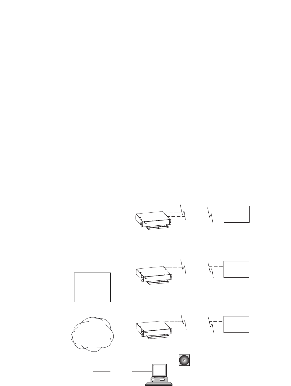
2.1 Basic System Components
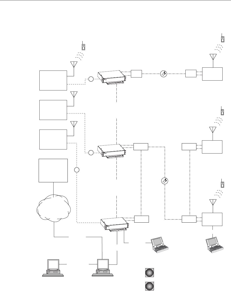
The basic components of a typical Digivance LRCS system and their function are shown in
Figure 1-1. A basic LRCS system consists of a Host Unit (HU) and a Remote Unit (RU). The
HU consists of a single-unit assembly that mounts in a standard equipment rack. The RU
consists of multiple electronic and optical modules that mount in either an outdoor cabinet or an
indoor mounting shelf. Control and monitoring functions are provided by the Digivance
Element Management System (EMS). In addition, various accessory items including a back-up
battery for the RU, a passive Wavelength Division Multiplexer (WDM) system, and an active
Coarse Wavelength Division Multiplexer (CWDM) system are available as accessories.
ADCP-75-179 • Preliminary Issue A • September 2004 • Section 1: Overview
Page 1-2
© 2004, ADC Telecommunications, Inc.
Figure 1-1. System Overview Diagram
HOST UNIT 1
HOST UNIT 2
HOST UNIT 3
NETWORK
OPERATIONS
CENTER
(REMOTE
INTERFACE)
CONTROLLER
AREA
NETWORK
20007-A
RF
RF
RF
CONTROLLER
AREA
NETWORK
CWDM
WDM REMOTE
UNIT 1
REMOTE
UNIT 3
WDM
REMOTE
UNIT 2
CWDM
CWDM
CWDM
BASE STATION
ANTENNA
PC COMPUTER WITH EMS
AND SNMP PROXY AGENT
(PERMANENT CONNECTION)
RS-232
ASCII
RS-232
CD-ROM WITH EMS
SOFTWARE
NETWORK SNMP
MANAGER
CD-ROM WITH SNMP PROXY
AGENT SOFTWARE
ETHERNET
LAN
PC COMPUTER WITH EMS
(TEMPORARY CONNECTION)
T1, DS0
WITH RS232
CONVERSION,
OR OTHER
MEDIUM
RS-232
RS-232
ENHANSED
BASE
TRANSCEIVER
STATION 1
ENHANSED
BASE
TRANSCEIVER
STATION 2
ENHANSED
BASE
TRANSCEIVER
STATION 3
ADCP-75-179 • Preliminary Issue A • September 2004 • Section 1: Overview
Page 1-3
© 2004, ADC Telecommunications, Inc.
2.2 Enhanced Base Transceiver Station Interface
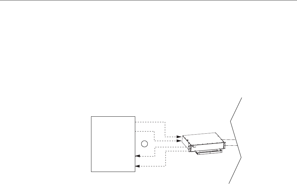
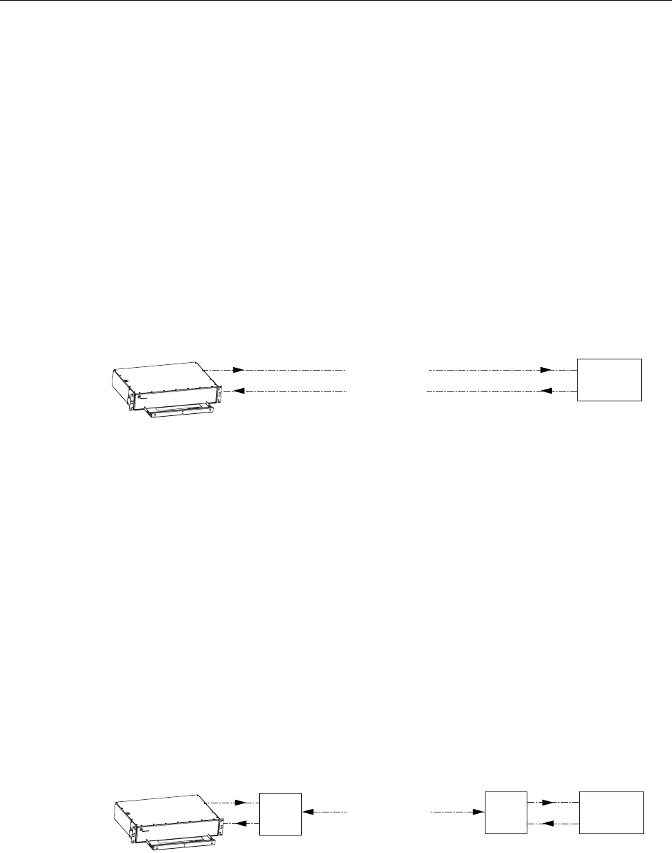
The HU is interfaced with an EBTS over coaxial cables as shown in Figure 1-2. The EBTS
provides the RF channel inputs and outputs for a designated sector. In the forward path, the HU
receives two RF inputs from the EBTS. The HU digitizes the RF signals and then converts them
to digital optical signals for transport to the RU. In the reverse path, the HU receives digital
optical signals from the RU. The HU converts the digital optical signals back to two RF outputs
which are supplied to the EBTS over the coaxial cable interface.
Figure 1-2. EBTS/HU Interface
2.3 Handset Interface
The RU interfaces with the handsets (cell phones) through an antenna. In the reverse path, the
RU receives RF signals from each handset (see Figure 1-1). The RU digitizes the RF signals and
then converts them to digital optical signals for transport to the HU over the optical fiber link. In
the forward path, the RU receives digital optical signals from the HU. The RU converts the
optical signals to RF signals for transmission to the handsets. The RU is connected to an
antenna (not provided) which transmits and receives the handset RF signals.
2.4 Local Interface
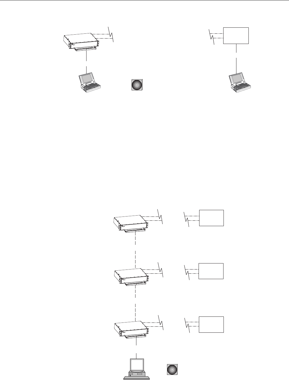
Communications with an individual Digivance system is supported through a local interface
capability as shown in Figure 1-3. A local interface requires a PC-type computer loaded with
the Digivance Element Management System (EMS) software. EMS provides the various control
and monitoring functions required to locally manage a Digivance system. The EMS computer
can be directly connected to either the HU or RU through the computer’s RS-232 port.
Operation is implemented through the EMS Graphical User Interface (GUI). The GUI consists
of a series of screens from which the user selects the desired option or function. An RS-232
service port is provided on both the HU and the RU for connecting the EMS computer.
20008-A
HOST UNIT
RF
ENHANCED
BASE
TRANSCEIVER
STATION
FORWARD
PATHS
REVERSE
PATHS
ADCP-75-179 • Preliminary Issue A • September 2004 • Section 1: Overview
Page 1-4
© 2004, ADC Telecommunications, Inc.
Figure 1-3. Local Management of a Single Digivance System
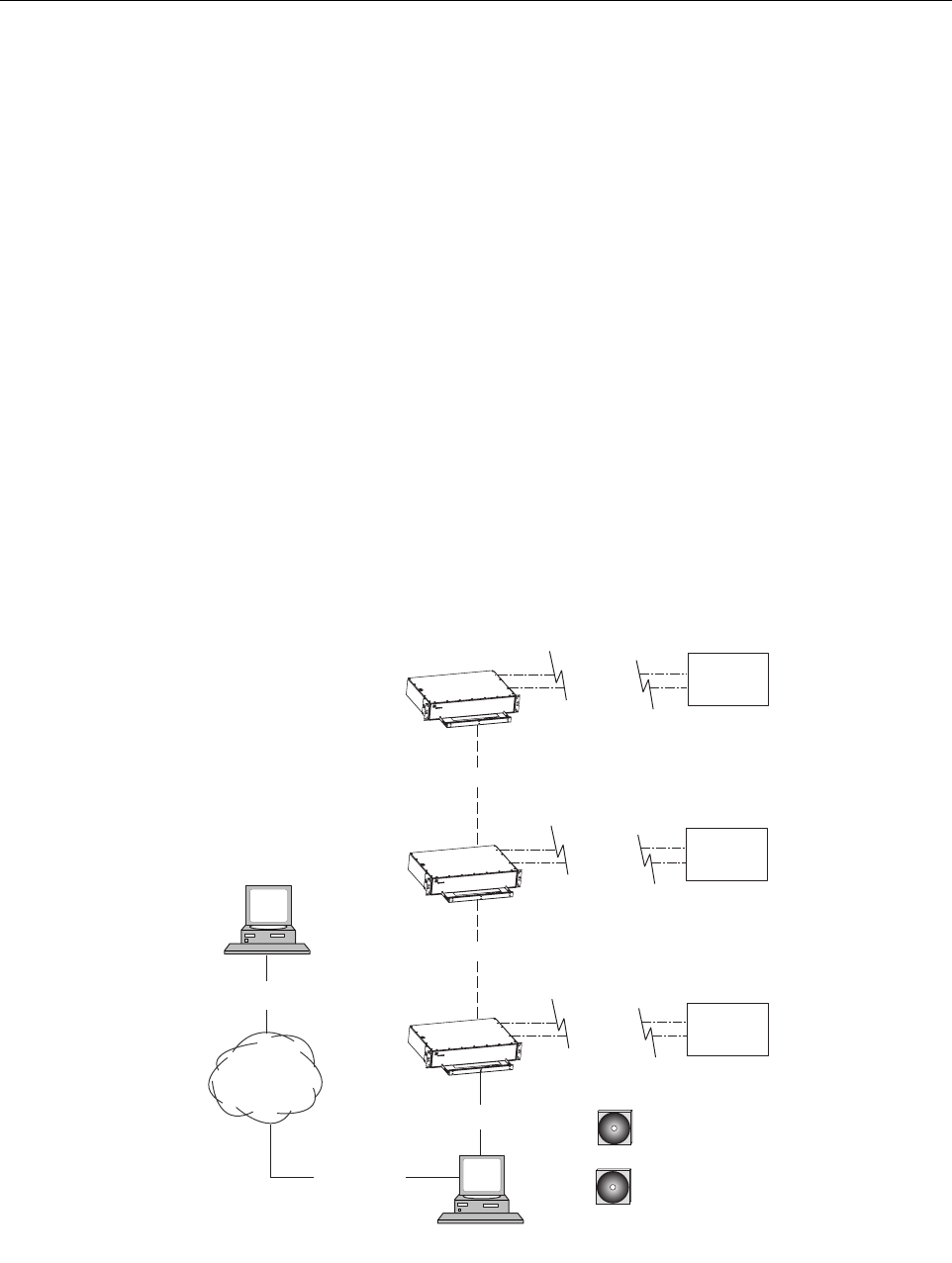
An EMS computer may be used to locally manage a networked group of multiple Digivance
systems as shown in Figure 1-4. A Controller Area Network (CAN) port is provided on each
HU. Up to twenty-four HU’s may be linked together through the CAN interface and controlled
by the same EMS computer. All the networked HU’s and the associated RU’s may be managed
by connecting the EMS computer to one HU. The EMS computer provides an RS-232 port (#1)
to support the interface with the networked HU’s.
Figure 1-4. Local Management of Networked Digivance Systems
HOST UNIT
LAPTOP WITH EMS
(LOCAL INTERFACE)
LAPTOP WITH EMS
(LOCAL INTERFACE)
18524-A
CD-ROM WITH DIGIVANCE
ELEMENT MANAGEMENT
SYSTEM (EMS) SOFTWARE
REMOTE
UNIT
RS-232
RS-232
PC COMPUTER WITH EMS
(LOCAL INTERFACE WITH
MULTIPLE SYSTEMS)
HOST UNIT
HOST UNIT
HOST UNIT
RS-232
20009-A
CD-ROM WITH DIGIVANCE
ELEMENT MANAGEMENT
SYSTEM (EMS) SOFTWARE
CAN
CAN
REMOTE
UNIT
REMOTE
UNIT
REMOTE
UNIT
ADCP-75-179 • Preliminary Issue A • September 2004 • Section 1: Overview
Page 1-5
© 2004, ADC Telecommunications, Inc.
2.5 Network Operations Center Interface
Communications between a Network Operations Center (NOC) and a networked group of
multiple Digivance systems is supported by a NOC interface capability as shown in Figure 1-5.
To support the NOC interface, a PC-type computer loaded with the Digivance Element
Management System (EMS) software is required. EMS provides the various control and
monitoring functions required to remotely manage multiple Digivance systems through the
NOC interface.
A Controller Area Network (CAN) port is provided on each HU. Up to twenty-four HU’s may
be linked together through the CAN interface and controlled by the same EMS computer. All
the networked HU’s and the associated RU’s may be managed by connecting the EMS computer
to one HU. The EMS computer provides an RS-232 port (#1) to support the interface with the
networked HU’s.
The NOC can be linked to the EMS computer through a T1 system, DS0 with RS232
conversion, or some other medium. The EMS computer provides an RS-232 ASCII interface
port (#2) to support the interface with the NOC.
At the NOC, control and monitoring of the networked Digivance systems is implemented
through a Network Element Manager (NEM) interface which requires only a VT100 terminal/
emulator for operation. The NEM interface language consists of simple ASCII text strings. All
communications are input as either SET or GET commands which result in ASCII text string
responses from the specified system or systems.
Figure 1-5. Remote Management of Networked Digivance Systems Through NOC Interface
PC COMPUTER WITH
EMS SOFTWARE
HOST UNIT
HOST UNIT
HOST UNIT
RS-232
20010-A
CD-ROM WITH EMS
SOFTWARE
CAN
CAN
NETWORK
OPERATIONS
CENTER
(REMOTE
INTERFACE)
RS-232
ASCII
T1, DS0
WITH RS232
CONVERSION,
OR OTHER
MEDIUM
REMOTE
UNIT
REMOTE
UNIT
REMOTE
UNIT
ADCP-75-179 • Preliminary Issue A • September 2004 • Section 1: Overview
Page 1-6
© 2004, ADC Telecommunications, Inc.
2.6 SNMP Interface
Communications between an external Simple Network Management Protocol (SNMP) Manager
and a networked group of multiple Digivance systems is supported by an SNMP interface
capability as shown in Figure 1-6. To support the SNMP interface, a PC-type computer loaded
with both the Digivance Element Management System (EMS) software and the SNMP Proxy
Agent software is required. The EMS and SNMP Proxy Agent software plus the associated
Management Information Base (MIB) provide the various control (Set) and monitoring (Get)
functions required to remotely manage multiple Digivance systems using an SNMP Manager.
A Controller Area Network (CAN) port is provided on each HU. Up to twenty-four HU’s may
be linked together through the CAN interface and controlled by the same EMS computer. All
the networked HU’s and the associated RU’s may be managed by connecting the EMS computer
to one HU. The EMS computer provides an RS-232 port (#1) to support the interface with the
networked HU’s.
The SNMP Manager may be linked with the EMS computer through a Local Area Network
(LAN). The EMS computer provides an Ethernet port to support the interface with the LAN.
The SNMP Proxy Agent supports two versions of the SNMP protocol: SNMPv1 and SNMPv2c.
A facility to Register/Unregister an SNMP Manager for receiving traps is also supported by the
SNMP Proxy Agent. The SNMP Manager is not included with the EMS software and must be
provided separately.
Figure 1-6. Remote Management of Networked Digivance Systems Through SNMP Manager
PC COMPUTER WITH EMS
AND SNMP PROXY AGENT
HOST UNIT
HOST UNIT
HOST UNIT
RS-232
20011-A
CD-ROM WITH EMS
SOFTWARE
CD-ROM WITH SNMP
PROXY AGENT SOFTWARE
CAN
CAN
LOCAL
AREA
NETWORK
ETHERNET
NETWORK
SNMP
MANAGER
ETHERNET
REMOTE
UNIT
REMOTE
UNIT
REMOTE
UNIT
ADCP-75-179 • Preliminary Issue A • September 2004 • Section 1: Overview
Page 1-7
© 2004, ADC Telecommunications, Inc.
3 SYSTEM FUNCTIONS AND FEATURES
This section describes various system level functions and features of the Digivance system.
3.1 Fiber Optic Transport
In a typical Digivance system, the HU is connected to the RU over two single-mode optical
fibers. One fiber is used to transport the forward path optical signal. The other fiber is used to
transport the reverse path optical signal. Because the optical signal is digital, the input and
output RF signal levels at the HU or the RU are not dependent on the level of the optical signal
or the length of the optical fiber. A diagram of the fiber optic transport system for a typical
Digivance system is shown in Figure 1-7.
Figure 1-7. Standard Fiber Optic Transport Application
The maximum length of the optical links is dependent on the loss specifications of the optical
fiber and the losses imposed by the various connectors and splices. The system provides an
optical budget of 25 dB (typical) when used with 9/125 single-mode fiber.
In some applications, it may be desirable or necessary to combine the forward path and reverse
path optical signals from a single HU/RU pair onto a single optical fiber. This can be
accomplished by using a passive bi-directional Wavelength Division Multiplexer (WDM)
system. The optical wavelengths used in the Digivance system are 1550 nm for the forward path
and 1310 nm for the reverse path. Because different wavelengths are used for the forward and
reverse paths, both signals can be combined on a single optical fiber. One WDM module is
mounted with the HU and the other WDM module is mounted with the RU as shown in
Figure 1-8. The WDM system is available as an accessory item.
Figure 1-8. Wavelength Division Multiplexer Application
HOST UNIT
18526-A
REMOTE
UNIT
FORWARD PATH
REVERSE PATH
FIBER OPTIC
LINK
HOST UNIT
18527-A
REMOTE
UNIT
FIBER OPTIC
LINK
WDM WDM
FORWARD AND
REVERSE PATH
ADCP-75-179 • Preliminary Issue A • September 2004 • Section 1: Overview
Page 1-8
© 2004, ADC Telecommunications, Inc.
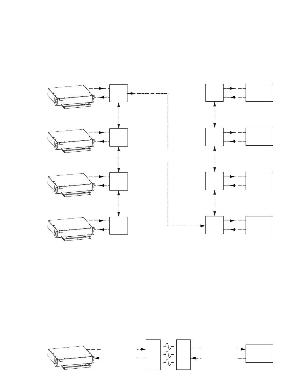
In some applications, it may be desirable or necessary to combine the forward and reverse path
optical signals from multiple HU’s and RU’s onto a single optical fiber. This can be
accomplished by using an active Coarse Wavelength Division Multiplexer (CWDM) system. Up
to four Digivance systems may be configured to operate over a single optical fiber. A CWDM
module is mounted with each HU and RU. An example of a typical CWDM application is
shown in Figure 1-9.
Figure 1-9. Coarse Wavelength Division Multiplexer Application
A Free Space Optics (FSO) system (that meets the Digivance LRCS data rate performance and
BER requirements) may be used in applications where it is desirable or necessary to bridge an
open span and where it is impractical to lay a fiber optic cable. One FSO transceiver unit may be
mounted on the HU side of the open span and the other FSO transceiver unit may be mounted
on the RU side of the open span. A system diagram of an FSO application is shown in
Figure 1-10. FSO systems are available from various equipment manufacturers.
Figure 1-10. Free Space Optics Application
18528-A
FIBER OPTIC
LINK
HOST UNIT 1
REMOTE
UNIT 1
CWDM
A
CWDM
A
HOST UNIT 2
REMOTE
UNIT 2
CWDM
B
CWDM
B
HOST UNIT 3
REMOTE
UNIT 3
CWDM
C
CWDM
C
HOST UNIT 4
REMOTE
UNIT 4
CWDM
D
CWDM
D
FORWARD AND
REVERSE PATH
HOST UNIT
18530-A
REMOTE
UNIT
FORWARD PATH
FSO
TX/RX
FSO
TX/RX
FREE SPACE OPTICS LINK
REVERSE PATH
FORWARD PATH
REVERSE PATH

ADCP-75-179 • Preliminary Issue A • September 2004 • Section 1: Overview
Page 1-9
© 2004, ADC Telecommunications, Inc.
3.2 Control and Monitoring Software
The EMS software and the SNMP Proxy Agent software provide control and monitoring
functions for the Digivance system through the local, NOC, and SNMP interfaces. The EMS
and SNMP Proxy Agent software are stored on CD-ROM’s which are shipped in a separate
package along with the software user manuals. The EMS software package is available without
the SNMP Proxy Agent if the SNMP interface capability not required for the application.
Software installation consists of copying the software files from the CD-ROM’s to a designated
directory on the hard-drive of the EMS computer.
The EMS software provides the capability to provision and configure the Digivance system for
operation. This includes selecting a site name, setting alarm thresholds, and setting forward and
reverse path RF gain adjustments. The EMS software also provides the capability to get alarm
messages (individual or summary), obtain data measurements, and to upgrade the HU/RU
system software. All control and monitor functions (except software upgrade which is not
supported by the NOC/NEM and SNMP interfaces and HU/RU pair site number assignment
which is not supported by the SNMP interface) may be implemented using the NOC/NEM
interface, the SNMP interface, or the EMS software GUI.
3.3 Fault Detection and Alarm Reporting
LED indicators are provided on the front panel of the HU and on the front panels of the RU
modules to indicate if the system is normal or if a fault is detected. In addition, normally open
and normally closed alarm contacts (for both major and minor alarms) are provided at the HU
for connection to a customer-provided external alarm system. All alarms can also be accessed
through the NOC/NEM interface, SNMP manager, or the EMS software GUI.
3.4 Powering
The HU is powered by ±24 or ±48 VDC and must be hard-wired to a local office battery power
source through a fuse panel. A screw-down terminal strip is provided on the rear side of the HU
for the power connections.
The RU is powered by 120 or 240 VAC power (50 or 60 Hz) and must be connected to a 20 Amp
AC power source. If the RU modules are installed in an outdoor cabinet, the AC wiring is placed
in conduit and permanently connected to the internal cabinet wiring. If the RU modules are
installed in an indoor mounting shelf, a standard three-conductor AC power cord is provided for
connection to a standard AC power outlet. A back-up battery system is available for specified
outdoor cabinets as an accessory. The battery-backup system powers the RU if the AC power
source is disconnected or fails.
3.5 Equipment Mounting and Configuration
The HU is a single-unit assembly that is designed for mounting in a non-condensing indoor
environment such as inside a wiring closet or within an environmentally-controlled cabinet. The
HU is intended for rack-mount applications and may installed (usually within 20 feet of the
EBTS) in either a 19- or 23-inch, WECO or EIA, equipment rack.

ADCP-75-179 • Preliminary Issue A • September 2004 • Section 1: Overview
Page 1-10
© 2004, ADC Telecommunications, Inc.
The RU is designed for mounting in either an indoor or outdoor environment. The RU consists
of a Spectrum Transport Module (STM), a Linear Power Amplifier (LPA) module, WDM
remote module (accessory), CWDM remote module (accessory), and either an outdoor cabinet
or a indoor mounting shelf.
Several types of outdoor cabinets are available. Each outdoor cabinet is weather-tight but
contact with salt-air mist should be avoided as it may degrade the MTBF of the product. Out-
door cabinets can be mounted from a flat-vertical surface or a utility pole (requires pole-mount
kit). Slots are provided within each cabinet for mounting the STM and LPA modules and also
the WDM or CWDM remote modules. Storage spools are provided within the cabinet for
storing short lengths of excess fiber slack. Specified cabinets include a tray with a heated base
for mounting a back-up battery (accessory item).
A indoor mounting shelf for indoor use is also available. The indoor mounting shelf is designed
for installation in a non-condensing indoor environment such as inside a wiring closet or within
an environmentally-controlled cabinet. The indoor mounting shelf installs in a standard EIA or
WECO, 19- or 23-inch, equipment rack. Slots are provided within the mounting shelf for
mounting the STM and LPA modules and also the WDM or CWDM remote modules.

ADCP-75-179 • Preliminary Issue A • September 2004 • Section 2: Description
Page 2-1
© 2004, ADC Telecommunications, Inc.
SECTION 2: DESCRIPTION
1 INTRODUCTION. . . . . . . . . . . . . . . . . . . . . . . . . . . . . . . . . . . . . . . . . . . . . . . . . . . . . . . . . . . . . . . . . . . . . . . .2-3
2 HOST UNIT . . . . . . . . . . . . . . . . . . . . . . . . . . . . . . . . . . . . . . . . . . . . . . . . . . . . . . . . . . . . . . . . . . . . . . . . . . .2-3
2.1 Primary Components . . . . . . . . . . . . . . . . . . . . . . . . . . . . . . . . . . . . . . . . . . . . . . . . . . . . . . . . . . . . . .2-3
2.2 Mounting . . . . . . . . . . . . . . . . . . . . . . . . . . . . . . . . . . . . . . . . . . . . . . . . . . . . . . . . . . . . . . . . . . . . . .2-3
2.3 Fault Detection and Alarm Reporting . . . . . . . . . . . . . . . . . . . . . . . . . . . . . . . . . . . . . . . . . . . . . . . . . . .2-4
2.4 RF Signal Connections . . . . . . . . . . . . . . . . . . . . . . . . . . . . . . . . . . . . . . . . . . . . . . . . . . . . . . . . . . . . .2-4
2.5 RF Signal Level Adjustments. . . . . . . . . . . . . . . . . . . . . . . . . . . . . . . . . . . . . . . . . . . . . . . . . . . . . . . . .2-5
2.6 Propagation Delay . . . . . . . . . . . . . . . . . . . . . . . . . . . . . . . . . . . . . . . . . . . . . . . . . . . . . . . . . . . . . . . .2-5
2.7 Optical Connection . . . . . . . . . . . . . . . . . . . . . . . . . . . . . . . . . . . . . . . . . . . . . . . . . . . . . . . . . . . . . . .2-5
2.8 Controller Area Network Interface Connection . . . . . . . . . . . . . . . . . . . . . . . . . . . . . . . . . . . . . . . . . . . . .2-5
2.9 Service Interface Connection. . . . . . . . . . . . . . . . . . . . . . . . . . . . . . . . . . . . . . . . . . . . . . . . . . . . . . . . .2-5
2.10 Auxiliary Interface Connector . . . . . . . . . . . . . . . . . . . . . . . . . . . . . . . . . . . . . . . . . . . . . . . . . . . . . . . .2-5
2.11 Powering . . . . . . . . . . . . . . . . . . . . . . . . . . . . . . . . . . . . . . . . . . . . . . . . . . . . . . . . . . . . . . . . . . . . . .2-6
2.12 Cooling . . . . . . . . . . . . . . . . . . . . . . . . . . . . . . . . . . . . . . . . . . . . . . . . . . . . . . . . . . . . . . . . . . . . . . .2-6
2.13 User Interface . . . . . . . . . . . . . . . . . . . . . . . . . . . . . . . . . . . . . . . . . . . . . . . . . . . . . . . . . . . . . . . . . . .2-6
3 SPECTRUM TRANSPORT MODULE . . . . . . . . . . . . . . . . . . . . . . . . . . . . . . . . . . . . . . . . . . . . . . . . . . . . . . . . . . . 2-8
3.1 Primary Components . . . . . . . . . . . . . . . . . . . . . . . . . . . . . . . . . . . . . . . . . . . . . . . . . . . . . . . . . . . . . .2-8
3.2 Mounting . . . . . . . . . . . . . . . . . . . . . . . . . . . . . . . . . . . . . . . . . . . . . . . . . . . . . . . . . . . . . . . . . . . . . .2-9
3.3 Fault Detection and Alarm Reporting . . . . . . . . . . . . . . . . . . . . . . . . . . . . . . . . . . . . . . . . . . . . . . . . . . .2-9
3.4 Antenna Cable Connection . . . . . . . . . . . . . . . . . . . . . . . . . . . . . . . . . . . . . . . . . . . . . . . . . . . . . . . . . 2-10
3.5 RF Signal Level Adjustment . . . . . . . . . . . . . . . . . . . . . . . . . . . . . . . . . . . . . . . . . . . . . . . . . . . . . . . . 2-10
3.6 Optical Connection . . . . . . . . . . . . . . . . . . . . . . . . . . . . . . . . . . . . . . . . . . . . . . . . . . . . . . . . . . . . . . 2-10
3.7 Service Interface Connection. . . . . . . . . . . . . . . . . . . . . . . . . . . . . . . . . . . . . . . . . . . . . . . . . . . . . . . . 2-10
3.8 Auxiliary Interface Connection. . . . . . . . . . . . . . . . . . . . . . . . . . . . . . . . . . . . . . . . . . . . . . . . . . . . . . . 2-10
3.9 Powering . . . . . . . . . . . . . . . . . . . . . . . . . . . . . . . . . . . . . . . . . . . . . . . . . . . . . . . . . . . . . . . . . . . . . 2-10
3.10 Cooling . . . . . . . . . . . . . . . . . . . . . . . . . . . . . . . . . . . . . . . . . . . . . . . . . . . . . . . . . . . . . . . . . . . . . . 2-11
3.11 User Interface . . . . . . . . . . . . . . . . . . . . . . . . . . . . . . . . . . . . . . . . . . . . . . . . . . . . . . . . . . . . . . . . . . 2-11
4 35 WATT LINEAR POWER AMPLIFIER. . . . . . . . . . . . . . . . . . . . . . . . . . . . . . . . . . . . . . . . . . . . . . . . . . . . . . . . 2-13
4.1 Primary Components . . . . . . . . . . . . . . . . . . . . . . . . . . . . . . . . . . . . . . . . . . . . . . . . . . . . . . . . . . . . . 2-13
4.2 Mounting . . . . . . . . . . . . . . . . . . . . . . . . . . . . . . . . . . . . . . . . . . . . . . . . . . . . . . . . . . . . . . . . . . . . . 2-14
4.3 Fault Detection and Alarm Reporting . . . . . . . . . . . . . . . . . . . . . . . . . . . . . . . . . . . . . . . . . . . . . . . . . . 2-14
4.4 Powering . . . . . . . . . . . . . . . . . . . . . . . . . . . . . . . . . . . . . . . . . . . . . . . . . . . . . . . . . . . . . . . . . . . . . 2-14
4.5 Cooling . . . . . . . . . . . . . . . . . . . . . . . . . . . . . . . . . . . . . . . . . . . . . . . . . . . . . . . . . . . . . . . . . . . . . . 2-14
4.6 User Interface . . . . . . . . . . . . . . . . . . . . . . . . . . . . . . . . . . . . . . . . . . . . . . . . . . . . . . . . . . . . . . . . . . 2-14
5 REMOTE UNIT MOUNTING SHELF . . . . . . . . . . . . . . . . . . . . . . . . . . . . . . . . . . . . . . . . . . . . . . . . . . . . . . . . . . 2-16
5.1 Indoor Mounting Shelf . . . . . . . . . . . . . . . . . . . . . . . . . . . . . . . . . . . . . . . . . . . . . . . . . . . . . . . . . . . . 2-16
6 SLIM-STYLE REMOTE UNIT CABINETS . . . . . . . . . . . . . . . . . . . . . . . . . . . . . . . . . . . . . . . . . . . . . . . . . . . . . . . 2-17
6.1 Slim-Style Single-STM Cabinet . . . . . . . . . . . . . . . . . . . . . . . . . . . . . . . . . . . . . . . . . . . . . . . . . . . . . . 2-18
6.2 Slim-Style Dual-STM Cabinet . . . . . . . . . . . . . . . . . . . . . . . . . . . . . . . . . . . . . . . . . . . . . . . . . . . . . . . 2-20
7 ACCESSORY ITEMS . . . . . . . . . . . . . . . . . . . . . . . . . . . . . . . . . . . . . . . . . . . . . . . . . . . . . . . . . . . . . . . . . . . . 2-23
7.1 Remote Unit Back-up Battery Kit . . . . . . . . . . . . . . . . . . . . . . . . . . . . . . . . . . . . . . . . . . . . . . . . . . . . . 2-23
7.2 Wavelength Division Multiplexer System . . . . . . . . . . . . . . . . . . . . . . . . . . . . . . . . . . . . . . . . . . . . . . . 2-24
Content Page

ADCP-75-179 • Preliminary Issue A • September 2004 • Section 2: Description
Page 2-2
© 2004, ADC Telecommunications, Inc.
7.3 Coarse Wavelength Division Multiplexer System . . . . . . . . . . . . . . . . . . . . . . . . . . . . . . . . . . . . . . . . . . 2-25
8 DIGIVANCE ELEMENT MANAGEMENT SYSTEM . . . . . . . . . . . . . . . . . . . . . . . . . . . . . . . . . . . . . . . . . . . . . . . . . 2-26
8.1 Digivance EMS Primary Components . . . . . . . . . . . . . . . . . . . . . . . . . . . . . . . . . . . . . . . . . . . . . . . . . . 2-26
8.2 Software Installation . . . . . . . . . . . . . . . . . . . . . . . . . . . . . . . . . . . . . . . . . . . . . . . . . . . . . . . . . . . . . 2-28
8.3 Computer Operation . . . . . . . . . . . . . . . . . . . . . . . . . . . . . . . . . . . . . . . . . . . . . . . . . . . . . . . . . . . . . 2-28
8.4 Digivance EMS Computer Interface Connections . . . . . . . . . . . . . . . . . . . . . . . . . . . . . . . . . . . . . . . . . . 2-28
8.5 Digivance EMS User Interfaces . . . . . . . . . . . . . . . . . . . . . . . . . . . . . . . . . . . . . . . . . . . . . . . . . . . . . . 2-29
9 SPECIFICATIONS . . . . . . . . . . . . . . . . . . . . . . . . . . . . . . . . . . . . . . . . . . . . . . . . . . . . . . . . . . . . . . . . . . . . . 2-31
_________________________________________________________________________________________________________

ADCP-75-179 • Preliminary Issue A • September 2004 • Section 2: Description
Page 2-3
© 2004, ADC Telecommunications, Inc.
1 INTRODUCTION
This section describes the basic components of a typical Digivance 800/900 MHz SMR LRCS
system including the Host Unit (HU) and Remote Unit (RU). The HU consists of a single rack-
mount chassis. The RU consists of a Spectrum Transport Module (STM); a 35 Watt Linear
Power Amplifier (LPA) module; and either an outdoor cabinet or an indoor mounting shelf.
Also described in this section are various accessory items that may be used with the HU and RU
including the Wavelength Division Multiplexer (WDM) system, Coarse Wavelength Division
Multiplexer (CWDM) system, and RU back-up battery kit.
2 HOST UNIT
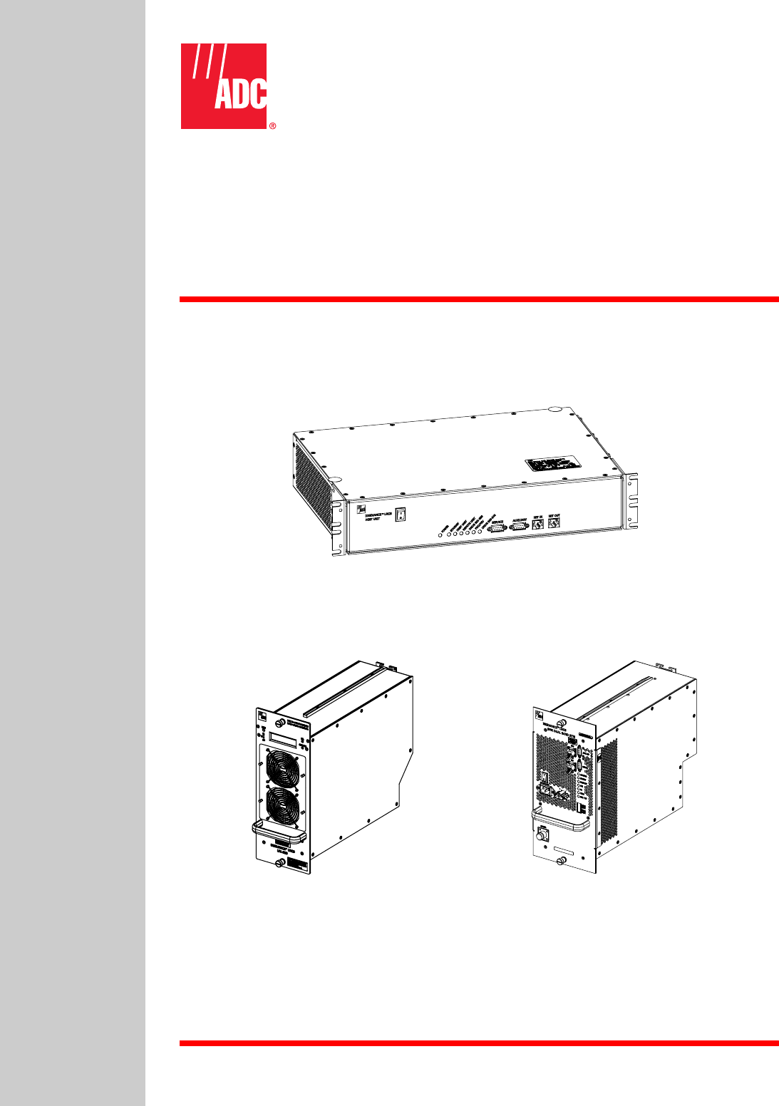
The HU, shown in Figure 2-1, provides the following basic functions:
• Provides an adjustable RF interface with the BTS.
• Provides a fiber optic interface with the RU.
• Digitizes the two forward path composite RF signals.
• Converts the two digitized forward path RF signals to a digital optical signal.
• Converts the digitized reverse path optical signal to two digitized RF signals.
• Converts the two digitized reverse path RF signals to two composite RF signals.
• Sends alarm information to an external alarm system through relay contact closures
• Provides an RS-232 interface for connecting the EMS computer.
• Provides an RS-232 interface for an auxiliary communications link with remote equipment.
• Provides a CAN interface for networking multiple HUs.
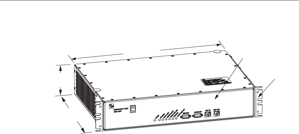
2.1 Primary Components
The HU consists of an electronic circuit board assembly and a fan assembly that are mounted
within a powder-paint coated sheet metal enclosure. The enclosure provides a mounting point
for the circuit board and fan assemblies and controls RF emissions. The only user-replaceable
component is the fan assembly. The HU is designed for use within a non-condensing indoor
environment such as inside a wiring closet or cabinet. The RF connectors, optical connectors,
alarm output connectors, DC power terminal strip, and grounding lug are mounted on the HU
rear panel. The On/Off power switch, LED indicators, service interface connector, and
Controller Area Network (CAN) connectors are mounted on the HU front panel.
2.2 Mounting
The HU is intended for rack-mount applications. A pair of reversible mounting brackets is
provided that allow the HU to be mounted in either a 19-inch or 23-inch EIA or WECO
equipment rack. When installed, the front panel of the HU is flush with the front of the rack.
Screws are provided for securing the HU to the equipment rack.
ADCP-75-179 • Preliminary Issue A • September 2004 • Section 2: Description
Page 2-4
© 2004, ADC Telecommunications, Inc.
Figure 2-1. Host Unit
2.3 Fault Detection and Alarm Reporting
The HU detects and reports various internal and external faults including host unit fault, optical
fault, power fault, temperature fault, and RF fault. Various front panel Light Emitting Diode
(LED) indicators turn from green to red or yellow if a fault is detected. A set of alarm contacts
(normally open and normally closed) are provided for reporting an alarm to an external alarm
system when a fault is detected. Both major alarm (system operation seriously affected) and
minor alarm (system operation not affected or only slightly degraded) contacts are provided.
Fault and alarm information may also be accessed locally through the EMS software GUI or
remotely through the NOC/NEM interface or SNMP interface. An alarm history file is
maintained by the EMS software so that a record is kept of all alarms as they occur. This is
useful when an alarm is reported and cleared before the reason for the alarm can be determined.
The status of the HU, the alarm state (major or minor), and other alarm information is
summarized and reported over the service interface, the CAN interface, and the optical interface
to the RU. In addition, the status of the RU is transmitted to the HU over the optical interface
and reported over the service interface and the CAN interface.
2.4 RF Signal Connections
The RF signal connections between the HU and the EBTS are supported through four N-type
female connectors. Two connectors are used for the forward path RF signals. The other two
connectors are used for the reverse path RF signals. In most installations, it is usually necessary
to install external attenuators to support the RF interface between the HU and the EBTS. The
HU should be as close as possible to the EBTS to minimize coaxial cable losses.
17.1 INCHES
(433 mm)
3.5 INCHES
(88 mm)
12.2 INCHES
(311 mm)
FRONT PANEL
MOUNTING
BRACKET
(BOTH SIDES)
20020-A

ADCP-75-179 • Preliminary Issue A • September 2004 • Section 2: Description
Page 2-5
© 2004, ADC Telecommunications, Inc.
2.5 RF Signal Level Adjustments
The HU is equipped with several attenuators for adjusting the signal levels of the forward and
reverse path RF signals. The attenuators provide an attenuation adjustment range of 0 to 31 dB
and can be set in 1 dB increments. The attenuators are software controlled and are adjusted
through the EMS software GUI, NOC/NEM interface, or SNMP interface.
The host forward path attenuators adjust the level of the two input RF signals to the HU.
Using the forward path attenuator, an input signal with a nominal composite signal level of –12
dBm to –43 dBm can be adjusted to produce maximum power output. Additional external
attenuation is required if the input signal level is greater than –12 dBm.
The host reverse path attenuators adjust the level of the two output RF signals from the HU
and will add from –1 dB of gain (attenuator set to 31 dB) to +30 dB of gain (attenuator set to 0
dB) to the two RF output signals at the HU.
2.6 Propagation Delay
The HU forward and reverse path propagation delays may be adjusted in 0.1 µsec increments
within a range of 0 to 63 µs. The propagation delay is software controlled and may be adjusted
through the EMS software GUI, NOC/NEM interface, or SNMP interface.
2.7 Optical Connection
Optical connections between the HU and the RU (STM) are supported through two SC-type
optical connector ports. One port is used for the forward path optical signal connection and the
other port is used for the reverse path optical signal connection.
2.8 Controller Area Network Interface Connection
Controller Area Network (CAN) interface connections between multiple HUs are supported by
a pair of RJ-45 jacks. One of the jacks is designated as the network IN port and the other jack is
designated as the network OUT port. The CAN interface allows up to 24 HUs to be connected
together (in daisy-chain fashion) and controlled through a single EMS computer.
2.9 Service Interface Connection
The service interface connection between the HU and the EMS computer is supported by a
single DB-9 female connector. The service connector provides an RS-232 DTE interface. When
multiple HUs are networked together, the supporting EMS computer may be connected to the
service connector of any one of the networked HUs.
2.10 Auxiliary Interface Connector
An auxiliary communication link is provided between the HU and the STM for customer use.
The auxiliary interface is supported by a single DB-9 female connector. The auxiliary connector
provides an RS-232 DTE interface. The auxiliary communications link can be used to remotely
monitor and control other network equipment that may be located at the remote unit site such as
the antenna.
ADCP-75-179 • Preliminary Issue A • September 2004 • Section 2: Description
Page 2-6
© 2004, ADC Telecommunications, Inc.
2.11 Powering
The HU is powered by ± 21 to ± 60 VDC power (nominal ± 24 or ± 48 VDC). The power is fed to
the HU through a screw-down type terminal strip located on the rear side of the unit. Power to
the HU must be supplied through a fuse panel such as the PowerWorx GMT Series Fuse Panel
(available separately). The power circuit for each HU must be protected with a 3 Amp GMT
fuse. An On/Off switch is provided on the HU front panel.
2.12 Cooling
Continuous airflow for cooling is provided by dual fans mounted on the right side of the HU
housing. A minimum of 3 inches (76 mm) of clearance space must be provided on both the left
and right sides of the HU for air intake and exhaust. An alarm is generated if a high temperature
condition (>50º C/122º F) occurs. The fans may be field-replaced if either fan fails.
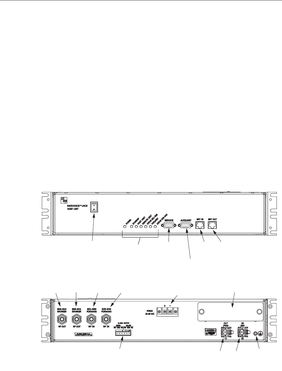
2.13 User Interface
The HU user interface consists of the various connectors, switches, terminals, and LEDs that are
provided on the HU front and rear panels. The HU user interface points are indicated in
Figure 2-2 and described in Table 2-1.
Figure 2-2. Typical Host Unit User Interface
(1) DC POWER
ON/OFF SWITCH
(21)
REV
(20)
FWD
(REFERENCE
ITEMS 2 - 8)
LED INDICATORS
(9) SERVICE
INTERFACE
CONNECTOR
(11) NET IN
CONNECTOR
(10) AUXILIARY
CONNECTOR
(12) NET OUT
CONNECTOR
(19) ALARM
OUTPUT CONNECTOR
(13) 806-824
REVERSE
(15) 851-869
FORWARD
(16) 935-940
FORWARD
(14) 896-901
REVERSE
20021-A
(17) DC POWER
TERMINAL STRIP
REAR VIEW
FRONT VIEW
(18) COVER PLATE
(22)
GROUNDING
STUD

ADCP-75-179 • Preliminary Issue A • September 2004 • Section 2: Description
Page 2-7
© 2004, ADC Telecommunications, Inc.
Table 2-1. Host Unit User Interface
REF
NO
USER INTERFACE
DESIGNATION DEVICE FUNCTIONAL
DESCRIPTION
1I/0 On/Off rocker
switch Provides DC power on/off control.
2 POWER Multi-colored LED
(green/yellow)
Indicates if the HU is powered (green) or unpow-
ered (off). See Note.
3 STANDBY Multi-colored LED
(green/yellow/red)
Indicates if the system is in the Normal (off),
Standby (blinking green), Test (blinking red), or
Program Load (blinking yellow) state. See Note.
4 HOST UNIT Multi-colored LED
(green/yellow/red)
Indicates if the HU is normal (green), overheated
(yellow), or faulty (red). See Note.
5 REMOTE UNIT Multi-colored LED
(green/yellow/red)
Indicates if no alarms (green), a minor alarm
(yellow), or a major alarm (red) is reported by the
RU. See Note.
6 DRIVE 851–869 Multi-colored LED
(green/yellow/red)
Indicates if the level of the 851–869 MHz RF
input signal to the HU is normal (green), low
(yellow), or high (red). See Note.
7FWD/REV
(PORT 1/PORT 2)
Multi-colored LED
(green/red)
Indicates if the reverse/forward path optical sig-
nals from the STM/HU are normal (green), if no
signals are detected (red), or if excessive errors
are detected (red). See Note.
8 DRIVE 935–940 Multi-colored LED
(green/yellow/red)
Indicates if the level of the 935–940 MHz RF
input signal to the HU is normal (green), low
(yellow), or high (red). See Note.
9 SERVICE DB-9 connector
(female) Connection point for the RS-232 service inter-
face cable.
10 AUXILIARY DB-9 connector
(female) Connection point for the RS-232 auxiliary inter-
face cable.
11 NET IN RJ-45 jack (female) Connection point for the CAN interface input
cable.
12 NET OUT RJ-45 jack (female) Connection point for the CAN interface output
cable.
13 806–824 REVERSE N-type female RF
coaxial connector Output connection point for the 806–824 MHz
reverse path RF coaxial cable.
14 896–901 REVERSE N-type female RF
coaxial connector Output connection point for the 896–901 MHz
reverse path RF coaxial cable.
15 851–869 FORWARD N-type female RF
coaxial connector Input connection point for the 851–869 MHz for-
ward path RF coaxial cable.
16 935–940 FORWARD N-type female RF
coaxial connector Input connection point for the 935–940 MHz for-
ward path RF coaxial cable.
17 POWER 24–48 VDC Screw-type terminal
strip Connection point for the DC power wiring.
18 No designation Cover plate Covers the mounting slot for the wavelength divi-
sion multiplexer module.

ADCP-75-179 • Preliminary Issue A • September 2004 • Section 2: Description
Page 2-8
© 2004, ADC Telecommunications, Inc.
3 SPECTRUM TRANSPORT MODULE
The STM, shown in Figure 2-3, provides the following basic functions:
• Provides an RF interface (antenna port) for the remote antenna(s).
• Provides an optical interface for the HU.
• Converts the digitized forward path optical signal to digitized RF signals.
• Converts the digitized forward path RF signals to two composite RF signals.
• Digitizes the two reverse path composite RF signals.
• Converts the digitized reverse path RF signals to a digitized optical signal.
• Provides an RS-232 interface for connecting a local EMS computer.
• Provides an RS-232 interface for an auxiliary communications link with remote equipment.
• Transports alarm, control, and monitoring information to the HU via the optical interface.
• Accepts AC power input and battery power input.
• Accepts external alarm input.
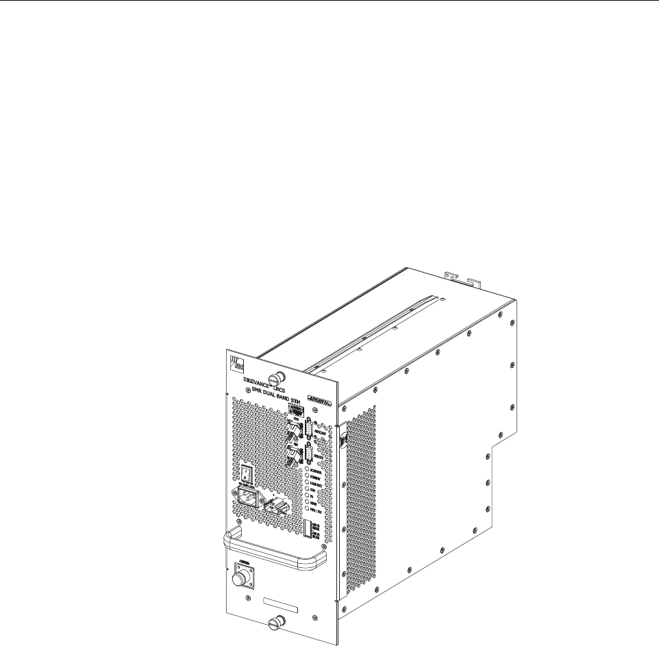
3.1 Primary Components
The STM consists of an electronic circuit board assembly, power supply, quadraplexer, and fan
assembly that are mounted within a powder-paint coated sheet metal enclosure. The metal
enclosure provides a mounting point for the electronic components and controls RF emissions.
Except for the fan unit, the electronic components are not user replaceable. The STM is
designed for use within the RU outdoor cabinet or indoor mounting shelf. Except for the LPA
interface connector, all controls, connectors, indicators, and switches are mounted on the STM
front panel for easy access. A carrying handle is provided on the front of the STM to facilitate
installation and transport.
19 ALARM OUTPUT Screw-type terminal
connector (14–26
AWG)
Connection point for an external alarm system.
Includes normally open (NO), normally closed
(NC), and common (COM) wiring connections.
20 FWD (PORT 1) SC connector
(single-mode) Output connection point for the forward path
optical fiber.
21 REV (PORT 2) SC connector
(single-mode) Input connection point for the reverse path pri-
mary optical fiber.
22 Chassis ground stud Connection point for a chassis grounding wire.
Note: A more detailed description of LED operation is provided in Section 4.
Table 2-1. Host Unit User Interface, continued
REF
NO
USER INTERFACE
DESIGNATION DEVICE FUNCTIONAL
DESCRIPTION
ADCP-75-179 • Preliminary Issue A • September 2004 • Section 2: Description
Page 2-9
© 2004, ADC Telecommunications, Inc.
3.2 Mounting
The STM mounts within the RU outdoor cabinet or indoor mounting shelf. Runners on the top
and bottom of the STM mesh with tracks in the cabinet or mounting shelf. The runners and
tracks guide the STM into the installed position. The electrical interface between the STM and
LPA is supported by a D-sub female connector located on the rear side of the STM. A
corresponding D-sub male connector mounted at the rear of the RU cabinet or indoor mounting
shelf mates with the STM connector. Captive screws are provided for securing the STM in the
installed position.
Figure 2-3. Typical Spectrum Transport Module
3.3 Fault Detection and Alarm Reporting
The STM detects and reports various faults including remote unit fault, optical fault, power
fault, temperature fault, power amplifier fault, and external (cabinet door open) fault. Various
front panel Light Emitting Diode (LED) indicators turn from green to red or yellow if a fault is
detected. The status of the STM, the alarm state (major or minor), and other alarm information
is summarized and reported over the optical interface to the HU and also over the service
interface. In addition, the alarm state of the HU is received over the optical interface and
reported to the service interface. Fault and alarm information may be accessed locally through
the EMS software GUI or remotely through the NOC/NEM interface or SNMP interface.
20023-B

ADCP-75-179 • Preliminary Issue A • September 2004 • Section 2: Description
Page 2-10
© 2004, ADC Telecommunications, Inc.
3.4 Antenna Cable Connection
The antenna cable connection between the STM and the antenna is supported through a single
N-type female connector. The single connector is used for the antenna cable which carries both
the forward and primary reverse path RF signals.
3.5 RF Signal Level Adjustment
The STM is equipped with digital attenuators for adjusting the signal level of the forward path
RF output signals. The remote forward path attenuators adjust the level of the two output RF
signals at the RU antenna port and will add from 0 to 31 dB of attenuation to the output signal
level. The attenuator can be set in 1 dB increments. The attenuator is software controlled and is
adjusted through the EMS software GUI, the NOC/NEM interface, or SNMP interface.
3.6 Optical Connection
Fiber optic connections between the STM and the HU are supported through two SC-type
optical connector ports. One port is used for the forward path optical signal connection and the
other port is used for the reverse path optical signal connection.
3.7 Service Interface Connection
The service interface connection between the STM and a local laptop computer loaded with the
EMS software is supported by a single DB-9 female connector. The service interface connector
provides an RS-232 DTE interface. The STM service interface supports local communications
with both the STM and the corresponding HU.
3.8 Auxiliary Interface Connection
An auxiliary communication link is provided between the HU and the STM for customer use.
The auxiliary interface is supported by a single DB-9 female connector. The auxiliary connector
provides an RS-232 DTE interface. The auxiliary communications link can be used to remotely
monitor and control other network equipment that may be located at the remote unit site such as
the antenna.
3.9 Powering
The STM is powered by 120 or 240 VAC (50 or 60 Hz) power which is supplied through a
three-conductor AC power cord. The power cord is provided with the RU outdoor cabinet or
indoor mounting shelf. The power cord connects to a 3-wire AC connector mounted on the front
panel. A switch on the STM front panel provides AC power On/Off control.
The STM (and the connected LPA) may be powered by a 24 VDC back-up battery system
which is available as an accessory kit. A connector is provided on the STM front panel for the
back-up battery system wiring harness connection.
ADCP-75-179 • Preliminary Issue A • September 2004 • Section 2: Description
Page 2-11
© 2004, ADC Telecommunications, Inc.
3.10 Cooling
Continuous air-flow for cooling is provided by a single fan mounted on the rear side of the STM
housing. An alarm is generated if a high temperature condition (>50º C/122º F) occurs. If the
temperature falls below 32º F (0º C), the fan automatically shuts off. The fan may be field
replaced if it fails.
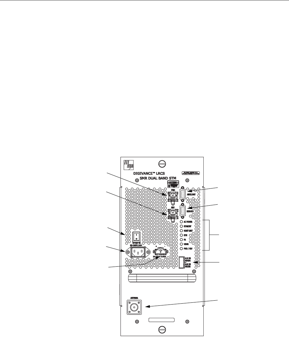
3.11 User Interface
The STM user interface consists of the various connectors, switches, and LEDs that are
provided on the STM front panel. The STM user interface points are indicated in Figure 2-4 and
described in Table 2-2.
Figure 2-4. Typical Spectrum Transport Module User Interface
20022-B
(3) ON/OFF
SWITCH
(4) AC POWER
CONNECTOR
(5) DC POWER
CONNECTOR
(1) FWD
CONNECTOR
(2) REV
CONNECTOR
(7) SERVICE
CONNECTOR
(6) AUXILIARY
CONNECTOR
(8-14) LED
INDICATORS
(15) ALARM
CONNECTOR
(16) ANTENNA
CONNECTOR