ADC Telecommunications DLCSMR3D Digivance LRCS SMR Dual Band System User Manual 75179
ADC Telecommunications Inc Digivance LRCS SMR Dual Band System 75179
Contents
- 1. manual1
- 2. manual2
- 3. manual3
manual3
ADCP-75-179 • Preliminary Issue A • September 2004 • Section 3: Operation
Page 3-11
© 2004, ADC Telecommunications, Inc.
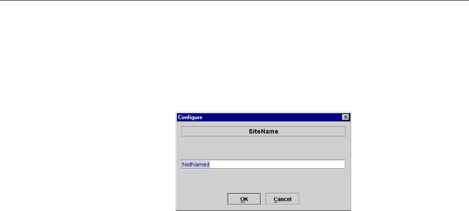
2. Click on the HOST Site Name Edit button (see Figure 3-6). The Site Name pop-up
screen will open as shown in Figure 3-7. Enter a unique name for the HOST. The name
may be up to 32 characters long and must not contain any spaces. The name may include
numbers, punctuation, and upper or lower case letters and must always begin with a letter.
Click on OK to close the screen and make the changes take effect.
Figure 3-7. HOST Site Name Pop-Up Screen
3. Click on the HOST Site Number Edit button (see Figure 3-6). The Site Number pop-up
screen will open. Enter any number (must be unique) between 1 and 24 and then click on
OK to close the screen and make the changes take effect.
4. Check the REMOTE Site Number field (see Figure 3-6). The REMOTE Site Number
does not have to be entered. When the HOST Site Number is entered, the system will
automatically enter the same number for the REMOTE Site Number.
5. Click on the REMOTE Site Name Edit button (see Figure 3-6). The Site Name pop-up
screen will open. Enter a unique name for the REMOTE. The name may be up to 32
characters long and must not contain any spaces. The name may include numbers,
punctuation, and upper or lower case letters and must always begin with a letter. Click on
OK to close the screen and make the changes take effect.
6. Open the Tools menu at the top of the main window and then select Refresh Catalog to
make the new Host and Remote site names appear in the View menu.
2.5 Enter Host Forward Attenuation
The HU internal forward path attenuator setting determines the maximum composite output
signal level at the STM antenna port. The appropriate attenuation value for any particular
system is based on the number of channels the system is transporting and the signal level of the
composite forward path signals input at the host units RF IN ports. By default, the forward path
attenuator is set to 31 dB.
The maximum output power that can be provided by the system is 43.4 dBm (22 Watts). The
total forward path gain that is provided by the system (with host and remote forward attenuators
set to 0 dB) is 85 dBm. Use the following procedure to set the forward path attenuation to
provide the maximum composite output signal level:
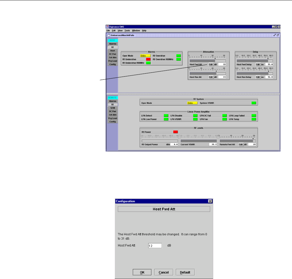
1. Click on the HOST RF tab. The HOST RF display will open within the EMS main
window as shown in Figure 3-8.
ADCP-75-179 • Preliminary Issue A • September 2004 • Section 3: Operation
Page 3-12
© 2004, ADC Telecommunications, Inc.
Figure 3-8. HOST RF Display
2. Click on the Host Fwd Att Edit button (see Figure 3-8). The Host Fwd Att pop-up screen
will open as shown in Figure 3-9.
Figure 3-9. Host Fwd Att Pop-Up Screen
3. Obtain the value of the total composite input signal level as determined in step 11 of
Section 2.3.
4. Determine the appropriate value to enter for the Host forward path attenuator by
subtracting the required system output level (per system design plan) from the system gain
(85 dB) and then adding the composite input signal level. The result (see sample
calculation) is the amount of attenuation required.
Atten = (System Gain) – (Required System Output Power) + (Composite Input Power)
5. Enter the attenuation value and click OK to close the pop-up screen and to make the
changes take effect.
Click on Edit button
to open Host Fwd
Att pop-up screen

ADCP-75-179 • Preliminary Issue A • September 2004 • Section 3: Operation
Page 3-13
© 2004, ADC Telecommunications, Inc.
2.6 Determine Output Signal Level at STM Antenna Port
The RF output signal level should be measured at the STM ANTENNA port to verify that
maximum composite signal level is at the required level. Use the following procedure to
determine the power level:
1. Verify that RF ON/OFF switch on the LPA is in the OFF position.
2. Disconnect the antenna cable from the STM ANTENNA port.
3. Connect a spectrum analyzer or RF power meter to the STM ANTENNA port. (Check the
input rating of the test equipment. Insert a 30 dB 100 W attenuator if necessary.)
4. Place the RF switch on the LPA in the ON position.
5. If using a spectrum analyzer, proceed to step 6. If using a power meter, measure the
composite signal power from the STM and then proceed to step 8.
6. Measure the RF level of a single carrier, such as the control channel, in dBm. Make sure
the resolution bandwidth of the spectrum analyzer is 30 kHz.
7. Calculate the total composite signal power using the following formula:
Ptot = Pc + 10Log N
Where,
Ptot is the total composite power in dBm
Pc is the power per carrier in dBm as measured in step 6, and
N is the total number of channels.
8. Record the result measured in step 5 or calculated in step 7.
9. Place the RF switch on the LPA in the OFF position.
10. Disconnect the spectrum analyzer or RF power meter from the STM ANTENNA port.
11. Re-connect the antenna cable to the STM ANTENNA port.
2.7 Enter Remote Forward Attenuation
The STM internal forward path attenuator setting is used to reduce the power level of the
composite output signals at the STM antenna port. The maximum composite output signal level
at the STM antenna port is set using the Host internal forward attenuator (see Section 2.5).
However, component variations may result in the output power at the STM antenna port being
slightly above or below the required power per channel. If this is the case, the STM forward
attenuator may be used in conjunction with the Host forward attenuator to add or remove
attenuation to produce the required output signal level. If less power is required, the STM
forward attenuator may be used to reduce the power level. The default setting is 31 dB. Use the
following procedure to change the STM forward attenuation:
Note: To comply with Maximum Permissible Exposure (MPE) requirements, the
maximum composite output from the antenna cannot exceed 1000 Watts EIRP and the
antenna must be permanently installed in a fixed location that provides at least 6 meters
(20 feet) of separation from all persons.
ADCP-75-179 • Preliminary Issue A • September 2004 • Section 3: Operation
Page 3-14
© 2004, ADC Telecommunications, Inc.
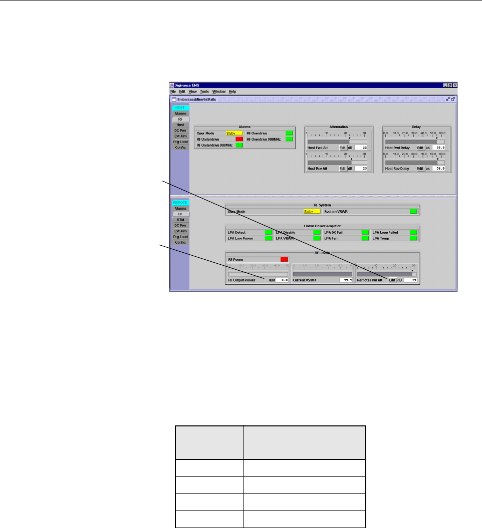
1. Click on the REMOTE RF tab. The REMOTE RF display will open within the EMS main
window as shown in Figure 3-10.
Figure 3-10. REMOTE LPA Display
2. Check the level of the RF output signal (as determined in Section 2.6) against the system
design plan specifications. Table 3-2 shows the output signal level required to provide 5
watts per channel for systems with 1 to 4 channels. The maximum output signal level
permitted for the system is 43.4 dBm (22 Watts).
3. Determine if more or less attenuation is required to produce the required output signal level.
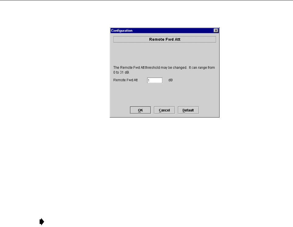
4. Click on the Remote Fwd Att field Edit button (see Figure 3-10). The Remote Fwd Att
pop-up screen will open as shown in Figure 3-11.
Table 3-2. Composite Output Signal Levels
NUMBER OF
CHANNELS
OUTPUT SIGNAL LEVEL
REQUIRED TO PROVIDE 5
WATTS PER CHANNEL
137 dBm
240 dBm
342 dBm
443 dBm
Click Edit button to
open the Remote Fwd
Att pop-up screen
RF output signal
level (± 3 dB)
ADCP-75-179 • Preliminary Issue A • September 2004 • Section 3: Operation
Page 3-15
© 2004, ADC Telecommunications, Inc.
Figure 3-11. Remote Fwd Att Pop-Up Screen
5. Enter the required attenuation value and click OK to close the pop-up screen and to make
the changes take effect.
6. Verify that the appropriate RF output signal level appears in the RF Output Power field
(see Figure 3-10). This is primarily a reference value and should not take the place of
external test equipment when determining the power level of the composite RF output
signal. Depending on the modulation type and number of channels, the EMS software may
report a power level that is higher or lower (± 3 dB) than the actual RF output signal.
2.8 Enter Host Reverse Attenuation
The level of the RF signal that should be input to the EBTS will vary depending on the type of
EBTS, the receive distribution, and the number of channels present. To interface with the EBTS,
the reverse path signal level must be adjusted to provide the signal level required by the EBTS.
The HU provides from –1 to +30 dB of gain in the reverse path. By default, the host reverse
attenuator is set to –31 dB of attenuation which provides –1 dB of gain. Use the following
procedure to set the reverse path gain:
1. Check the EBTS manufacturer’s specifications to determine the composite signal level
required at the 806–824 MHz and 896–901 MHz reverse path input ports.
2. Determine the overall gain and loss imposed on the signal by the antenna, antenna cable,
and by the cables that connect the HU to the EBTS.
3. Determine the amount of gain required to raise the reverse path signal to the level required
at the EBTS.
4. Click on the HOST RF tab. The HOST RF display will open within the EMS main
window as shown in Figure 3-12.
Note: To comply with Maximum Permissible Exposure (MPE) requirements, the
maximum composite output from the antenna cannot exceed 1000 Watts EIRP and the
antenna must be permanently installed in a fixed location that provides at least 6 meters
(20 feet) of separation from all persons.
ADCP-75-179 • Preliminary Issue A • September 2004 • Section 3: Operation
Page 3-16
© 2004, ADC Telecommunications, Inc.
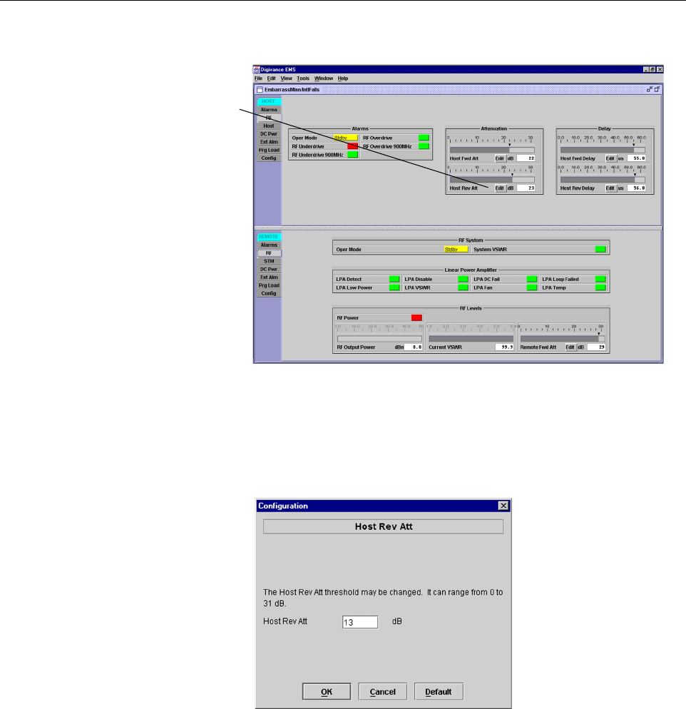
Figure 3-12. HOST RF Display
5. Click on the Host Rev Att field Edit button (see Figure 3-12). The Host Rev Att pop-up
screen will open as shown in Figure 3-13.
Figure 3-13. Host Rev Att Pop-Up Screen
6. Enter the attenuation value that will provide the required gain. Refer to Table 3-3 for the
attenuation values and the corresponding gain (nominal) values.
7. Click OK to close the pop-up screen and to make the changes take effect.
Click Edit button to
open the Host Rev Att
pop-up screen

ADCP-75-179 • Preliminary Issue A • September 2004 • Section 3: Operation
Page 3-17
© 2004, ADC Telecommunications, Inc.
2.9 Enter Host Forward and Reverse Delay
The forward and reverse delay function allows entry of from 0 to 63 µsec of delay in the
forward and reverse paths. This feature is used when multiple systems are used to transport the
same channel and there is a significant difference in the path delay between systems. Additional
delay may be entered to balance the overall system delay. The amount of delay required must be
calculated by the RF engineer and should be included in the system design plan. The default
setting is 0 µsec. Use the following procedure to change the forward and reverse path delay:
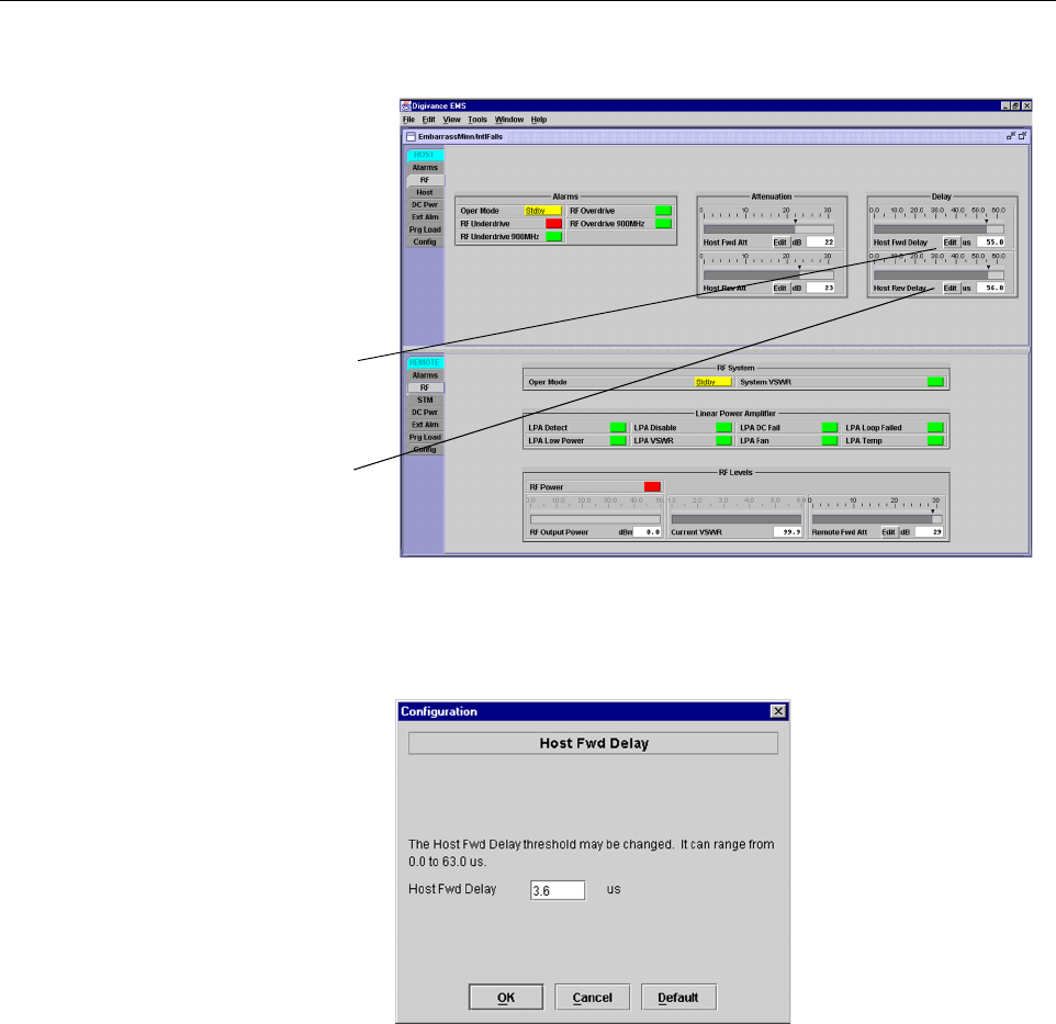
1. Click on the HOST RF tab. The HOST RF display will open within the EMS main
window as shown in Figure 3-14.
2. Click on the Host Fwd Delay field Edit button (see Figure 3-14). The Host Fwd Delay
pop-up screen will open as shown in Figure 3-15.
3. Obtain the value of the forward delay as specified in the system design plan. The delay is
adjustable in 0.1 µsec steps.
4. Enter the forward path delay value and click OK to close the pop-up screen and to make
the changes take effect.
5. Repeat the process for reverse delay by right-clicking on the appropriate delay section (see
Figure 3-14) and then entering the required delay value in the pop-up screen.
6. Click OK to close each pop-up screen and to make the changes take effect.
Table 3-3. Reverse Path Attenuation Setting and Nominal Gain Provided
ATTENUATION
SETTING
GAIN
PROVIDED
ATTENUATION
SETTING
GAIN
PROVIDED
ATTENUATION
SETTING
GAIN
PROVIDED
0 dB →30 dB 11 dB →19 dB 22 dB →8 dB
1 dB 29 dB 12 dB 18 dB 23 dB 7 dB
2 dB 28 dB 13 dB 17 dB 24 dB 6 dB
3 dB 27 dB 14 dB 16 dB 25 dB 5 dB
4 dB 26 dB 15 dB 15 dB 26 dB 4 dB
5 dB 25 dB 16 dB 14 dB 27 dB 3 dB
6 dB 24 dB 17 dB 13 dB 28 dB 2 dB
7 dB 23 dB 18 dB 12 dB 29 dB 1 dB
8 dB 22 dB 19 dB 11 dB 30 dB 0 dB
9 dB 21 dB 20 dB 10 dB 31 dB –1 dB
10 dB 20 dB 21 9 dB
ADCP-75-179 • Preliminary Issue A • September 2004 • Section 3: Operation
Page 3-18
© 2004, ADC Telecommunications, Inc.
Figure 3-14. HOST RF Display
Figure 3-15. Host Fwd Delay Pop-Up Screen
Click Edit button to
open the Host Fwd
Delay pop-up screen
Click Edit button to
open the Host Rev
Delay pop-up screen

ADCP-75-179 • Preliminary Issue A • September 2004 • Section 4: maintenance
Page 4-1
© 2004, ADC Telecommunications, Inc.
SECTION 4: MAINTENANCE
1 SYSTEM MAINTENANCE OVERVIEW . . . . . . . . . . . . . . . . . . . . . . . . . . . . . . . . . . . . . . . . . . . . . . . . . . . . . . . . . .4-1
1.1 Tools and Materials . . . . . . . . . . . . . . . . . . . . . . . . . . . . . . . . . . . . . . . . . . . . . . . . . . . . . . . . . . . . . . .4-1
2 FAULT DETECTION AND ALARM REPORTING. . . . . . . . . . . . . . . . . . . . . . . . . . . . . . . . . . . . . . . . . . . . . . . . . . . .4-2
3 FAULT ISOLATION AND TROUBLESHOOTING. . . . . . . . . . . . . . . . . . . . . . . . . . . . . . . . . . . . . . . . . . . . . . . . . . . . 4-6
3.1 Host Unit Troubleshooting. . . . . . . . . . . . . . . . . . . . . . . . . . . . . . . . . . . . . . . . . . . . . . . . . . . . . . . . . . .4-7
3.2 STM Troubleshooting . . . . . . . . . . . . . . . . . . . . . . . . . . . . . . . . . . . . . . . . . . . . . . . . . . . . . . . . . . . . . .4-9
3.3 LPA Troubleshooting . . . . . . . . . . . . . . . . . . . . . . . . . . . . . . . . . . . . . . . . . . . . . . . . . . . . . . . . . . . . . 4-13
4 TEST PROCEDURES. . . . . . . . . . . . . . . . . . . . . . . . . . . . . . . . . . . . . . . . . . . . . . . . . . . . . . . . . . . . . . . . . . . . 4-15
4.1 Optical Power Test. . . . . . . . . . . . . . . . . . . . . . . . . . . . . . . . . . . . . . . . . . . . . . . . . . . . . . . . . . . . . . . 4-15
4.2 Optical Loopback Test . . . . . . . . . . . . . . . . . . . . . . . . . . . . . . . . . . . . . . . . . . . . . . . . . . . . . . . . . . . . 4-17
5 SCHEDULED MAINTENANCE REQUIREMENTS . . . . . . . . . . . . . . . . . . . . . . . . . . . . . . . . . . . . . . . . . . . . . . . . . . 4-19
_________________________________________________________________________________________________________
1 SYSTEM MAINTENANCE OVERVIEW
This section explains the Digivance system fault detection and alarm reporting system, provides
a method for isolating and troubleshooting faults, and provides test procedures. The Digivance
system requires minimal regular maintenance to insure continuous and satisfactory operation.
Components that require regular replacement, cleaning, or testing include the HU fans, STM
fan, LPA fans, RU cabinet air-filter, and RU back-up battery.
Maintenance also includes diagnosing and correcting service problems as they occur. When an
alarm is reported, it will be necessary to follow a systematic troubleshooting procedure to locate
the problem. Once the source of the problem is isolated, the appropriate corrective action can be
taken to restore service. The only internal components that can be replaced are the cooling fans
which mount in the HU, RU, and LPA. The failure of any other internal component will require
replacement of the entire unit.
1.1 Tools and Materials
The following tools and materials are required in order to complete the maintenance procedures
specified in this section:
•ESD wrist strap
• IR filtering safety glasses
• Patch cords with SC connectors
• 15 dB in-line SC optical attenuators
• Optical power meter (1550 and 1310 nm)
• TORX screwdriver (with T10 bit)
• Battery maintenance tools (see PRC-SERIES OPERATING AND FIELD SERVICE
MANUAL for tool recommendations)

ADCP-75-179 • Preliminary Issue A • September 2004 • Section 4: maintenance
Page 4-2
© 2004, ADC Telecommunications, Inc.
2 FAULT DETECTION AND ALARM REPORTING
The Digivance LRCS on-board embedded software detects various unit and system faults which
generate ether a Major or Minor alarm. A Major alarm indicates that the system has failed in a
way that directly affects RF transport performance. When a major alarm occurs, all RF
functions are disabled and the system is out of service. A Minor alarm means that system
performance is not affected or in some cases, that the performance may no longer be optimal.
When a minor alarm occurs, RF functions continue and the system remains in service.
The following means are used to report Major and Minor alarms:
• HU alarm contacts
• HU, STM, and LPA front panel LED’s
• EMS software Graphical User Interface (GUI)
• Network Operations Center - Network Element Manager (NOC/NEM) interface
• SNMP interface
The HU is equipped with a set of both normally open (NO) and normally closed (NC) alarm
contacts which may be used to report both Major and Minor alarms to an external alarm system.
The alarm contacts summarize the inputs so that any Major or Minor alarm will trigger an alarm
report to the external alarm system.
The HU, STM, and LPA front panel LED indicators show status and alarm information by
displaying various colors: Green, Red, Yellow, and Off. In addition to LED indicators, the 35
Watt LPA is also equipped with a Digital Display that provides text messages. A description of
the Host Unit, Spectrum Transport Module, and 35 Watt LPA LED indicators is provided
respectively in Table 4-1, Table 4-2, and Table 4-3.
The EMS software GUI provides both a summary and a detailed list of alarm information that
includes unit and module level faults, circuit faults, and measured value faults such as voltages,
RF power, and temperature. A summary showing a list of all systems and their current alarm
status is presented through the Alarm OverView display. A more detailed list of alarm
information is presented through the HOST alarm display and the REMOTE alarm display. The
various fault conditions that trigger a major or minor alarm report are shown in the HOST and
REMOTE alarm displays.
The NOC/NEM interface provides the same summary and detailed listing of alarm information
as the EMS software GUI but in an ASCII text string format. Sending the command GET
ALARMSUMMARY produces a list of all systems and their current alarm status. Sending the
command GET ALARM ALL for a specific system will produce a detailed list of alarm
information for the specified system.
The SNMP interface provides alarm information to up to ten SNMP managers which must be
registered with the SNMP agent. The SNMP interface allows the SNMP managers to receive the
alarm and status information generated by the host and remote units. The presentation of the
alarm information is dependent on the features of the SNMP manager.

ADCP-75-179 • Preliminary Issue A • September 2004 • Section 4: maintenance
Page 4-3
© 2004, ADC Telecommunications, Inc.
Table 4-1. Host Unit LED Indicators
INDICATOR COLOR DESCRIPTION
POWER
Green
Off
Indicates if the HU is powered or un-powered.
The DC power source is on.
The DC power source is off.
STANDBY
Green (blinking)
Yellow (blinking)
Red (blinking)
Off
Indicates if the system is in the standby, normal, test, or
program load mode.
The HU is in the standby mode.
The HU is in the program load mode.
The HU is in the test mode.
The HU is in the normal mode.
HOST UNIT
Green
Yellow
Red
Indicates if the HU is normal, over temperature, if an
internal fault is detected, or if there is an equipment mis-
match.
The HU is normal.
The HU is over temperature or detects an internal fault.
The HU detects an internal fault or HU/RU band mismatch.
REMOTE UNIT
Green
Yellow
Red
Indicates if an alarm is detected at the RU.
No alarms detected at the RU.
A minor alarm is detected at the RU.
A major alarm is detected at the RU.
DRIVE 851–869
and
DRIVE 935–940
Green
Yellow
Red
Indicates if the specified forward path RF signal level is
normal, above overdrive threshold, or below underdrive
threshold.
The RF signal level is normal
The RF signal level is below the underdrive threshold.
The RF signal level is above the overdrive threshold.
FWD/REV
(PORT 1/PORT 2)
Green
Red
Indicates if the reverse path optical signals from the STM
are normal, if errors are detected, or if the optical signal is
not detected.
The reverse path optical signals are normal.
Excessive errors (see Note) are detected in the reverse path
optical signals or the HU is not receiving a reverse path optical
signal.
Note: Excessive errors means the Bit Error Rate (BER) has exceeded 10–6 (1 bit error per million bits).

ADCP-75-179 • Preliminary Issue A • September 2004 • Section 4: maintenance
Page 4-4
© 2004, ADC Telecommunications, Inc.
Table 4-2. Spectrum Transport Module LED Indicators
INDICATOR COLOR DESCRIPTION
AC POWER
Green
Red
Indicates if the STM is powered by the AC power source or
the back-up battery system.
The STM is powered by the AC power source.
The STM is powered by the back-up battery system.
STANDBY
Green (blinking)
Yellow (blinking)
Red (blinking)
Off
Indicates if the system is in the standby, normal, test, or
program load mode.
The STM is in the standby mode.
The STM is in the program load mode.
The STM is in the test mode.
The STM is in the normal mode.
HOST UNIT
Green
Yellow
Red
Indicates if an alarm is detected at the HU.
No alarms detected at the HU.
A minor alarm is detected at the HU.
A major alarm is detected at the HU.
STM
Green
Yellow
Red
Indicates if the STM is normal, over temperature, if a bat-
tery fault is detected, if an internal fault is detected, or if
there is an equipment mismatch.
The STM is normal.
The STM is over temperature due to high ambient tempera-
ture, the fan has failed, or detects an internal fault.
The STM detects an internal fault, the backup battery voltage
is below threshold, or HU/RU band mismatch.
PA
Green
Yellow
Red
Indicates if the LPA is normal, over temperature, has a fan
failure, has an internal fault, is shutdown, or not present.
The LPA is normal.
The LPA is over temperature or the fan has failed.
Internal fault detected in the LPA, the LPA RF power output is
shutdown, or the LPA is not present.
VSWR
Green
Red
Indicates if the forward path VSWR is above or below the
threshold.
The VSWR is below the threshold.
The VSWR is above the threshold.
FWD/REV
(PORT 1/PORT 2)
Green
Red
Indicates if the forward path optical signals from the HU
are normal, if errors are detected, or if the optical signal is
not detected.
The forward path optical signals are normal.
Excessive errors (see Note) are detected in the forward path
optical signal or the STM is not receiving the forward path
optical signal.
Note: Excessive errors means the Bit Error Rate (BER) has exceeded 10–6 (1 bit error per million bits).

ADCP-75-179 • Preliminary Issue A • September 2004 • Section 4: maintenance
Page 4-5
© 2004, ADC Telecommunications, Inc.
Table 4-3. 35 Watt LPA LED Indicators and Digital Display
INDICATOR COLOR DESCRIPTION
FAIL
Off
Yellow
Indicates if the LPA is normal or faulty.
The LPA is normal.
Internal fault detected in the LPA.
SHUTDOWN
Off
Red
Indicates if the LPA has an RF output or if the RF output
is shutdown.
The LPA RF output is on.
The LPA RF output is shutdown.
DISPLAY MESSAGE 1ST LINE DESCRIPTION
PA Initializing The LPA is initializing itself and is not ready for operation.
Normal Operation The LPA is enabled and transmitting RF.
Internal Shutdown The LPA is disabled due to a major fault and is not transmit-
ting RF.
Forced Shutdown The LPA is disabled by the front panel control switch or
through the EMS.
DISPLAY MESSAGE 2ND LINE DESCRIPTION
Over Power The LPA maximum RF output rating has been exceeded.
Over Temperature The LPA maximum operating temperature has been exceeded.
VSWR The voltage standing wave ratio is greater than 3:1.
DC Fail The LPA internal DC power supply is out of specification.
Low Gain The LPA internal amplifier gain is too low.
Alarm: OK The LPA does not detect any faults that would cause an alarm.
Loop Fail The LPA internal loop gain in out of range.
Fan Fail One or both of the LPA cooling fans has failed.
ADCP-75-179 • Preliminary Issue A • September 2004 • Section 4: maintenance
Page 4-6
© 2004, ADC Telecommunications, Inc.
3 FAULT ISOLATION AND TROUBLESHOOTING
Alarm information may be accessed using the HU and STM front panel LED indicators, the
EMS software GUI, the NOC-NEM interface, or the SNMP manager. When an alarm occurs,
use the unit LED indicators and any one of the specified software tools to determine which
Digivance system is affected, which unit (HU or STM) reported the alarm, and the fault that
generated the alarm. Then refer to either Section 3.1 Host Unit Troubleshooting or Section 3.2
STM Troubleshooting to isolate the problem and to determine the corrective action required. If
an LPA problem is reported by the STM, refer to Section 3.3 LPA Troubleshooting for the
troubleshooting procedures that apply to the LPA.
When attempting to isolate a problem, always determine the initial fault that generated the
alarm report. Some faults may cause additional faults to be reported which tends to obscure the
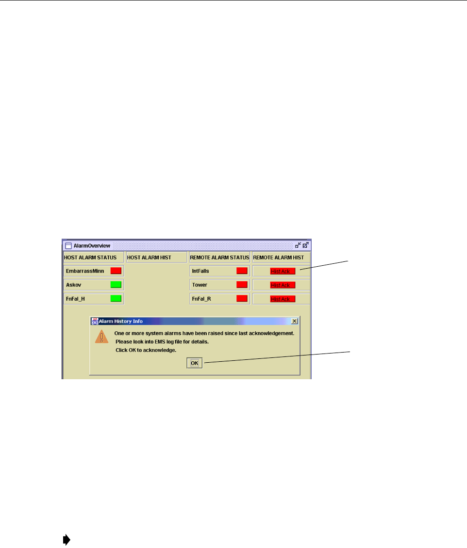
initial reason for the alarm. To help isolate faults, the EMS GUI provides an AlarmOverview
screen, shown in Figure 4-1, that indicates which Digivance system/unit is reporting the alarm.
Figure 4-1. AlarmOverView Screen
The AlarmOverview screen includes an ALARM HIST indicator which the user should click to
acknowledge that an alarm exists. Acknowledging the alarm opens the Alarm History Info
dialog box (also shown in Figure 4-1) which directs the user to view the EMS Log file for
details. The EMS Log file lists the various faults in the order in which they occurred. Clear each
fault starting with the initial fault. In most instances, clearing the initial fault will also clear any
remaining faults. For additional information on using the AlarmOverview screen, refer to the
Digivance Element Management System Version 3.01 User Manual (ADCP-75-151).
Note: It is recommended that if there are alarms at both the HU and STM, the optical
faults should be checked and cleared first. Because the HU and STM function as a system,
a fault in the fiber optic link will cause alarms to be reported by both the HU and STM.
Click to acknowledge
alarm and to open Alarm
History Info dialog box
Click to clear alarm
history fault indicator
and to close Alarm
History Info dialog box
ADCP-75-179 • Preliminary Issue A • September 2004 • Section 4: maintenance
Page 4-7
© 2004, ADC Telecommunications, Inc.
3.1 Host Unit Troubleshooting
Use this section to troubleshoot alarms that originate with the Host Unit. When a Minor alarm
occurs, one (or more) of the Host Unit LED’s with turn yellow and the EMS software will
indicate a minor fault/alarm. When a Major alarm occurs, one (or more) of the Host Unit LED’s
will turn red and the EMS software will indicate a major fault/alarm. Locate the LED and the
corresponding software fault/status indicator in Table 4-4 and then take the corrective action
indicated.
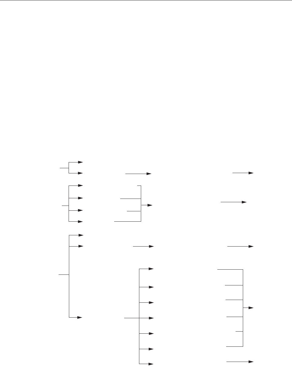
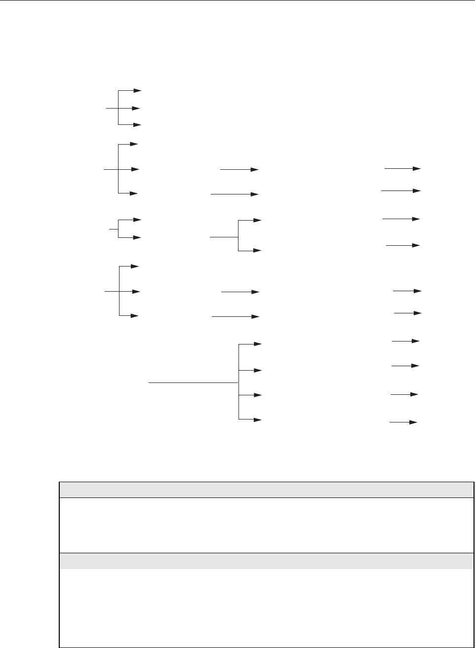
Table 4-4. Host Unit Fault/Alarm Isolation Diagram
Power
Host Unit Front Panel LED
Standby
Host
Unit
Green - Normal
Yellow - Minor Alarm
Red - Major Alarm
Green - Powered
Off - Not powered
Green blinking - Standby
Yellow blinking -
Program load
Red blinking - Test
Off - Normal
Temperature - Over temperature
LO Synth Lock - Local
oscillator synthesizer out of lock
Pri Rev Synth Lock - Reverse
primary synthesizer out of lock
8 Volt - Onboard 8 Volt power
supply below threshold
3.8 Volt - Onboard 3.8 Volt power
supply below threshold
Pri Fwd Mux Lock - Forward primary
phase locked loop out-of-lock
Pri Laser Fail - Forward primary
laser failure
Hardware mismatch - Host and
Remote band mismatch
Software Fault/Status Indicator
Replace HU
Table 4-5
Problem B
Replace HU or
STM with
correct unit
Corrective Action
or Reference
Oper Mode - Operational
mode of system
No specific HU faults - Only
faults with no associated LED
are displayed
Table 4-5
Problem A
Use EMS to
change system to
required mode
Continued
20013-A
ADCP-75-179 • Preliminary Issue A • September 2004 • Section 4: maintenance
Page 4-8
© 2004, ADC Telecommunications, Inc.
Table 4-5. Host Unit Fault/Alarm Corrective Action
PROBLEM A: The HU is not powered.
POSSIBLE CAUSE CORRECTIVE ACTION/COMMENTS
1. The HU is turned off.
2. The fuse is open/removed from the fuse panel
or the DC power has failed.
1. Place On/Off switch in the On position.
2. Check DC power source, repair as needed, and
replace or reinstall fuse at fuse panel.
PROBLEM B: The HU is overheating.
POSSIBLE CAUSE CORRECTIVE ACTION/COMMENTS
1. Air intake or exhaust opening to HU chassis
is blocked
2. Ambient temperature > 50º C/122º F.
3. Faulty fan.
4. The HU has failed.
1. Remove cause of air-flow blockage.
2. Reduce ambient temperature.
3. Replace HU fan (See applicable manual).
4. Replace HU.
Host Unit Front Panel LED Software Fault/Status Indicator Corrective Action
or Reference
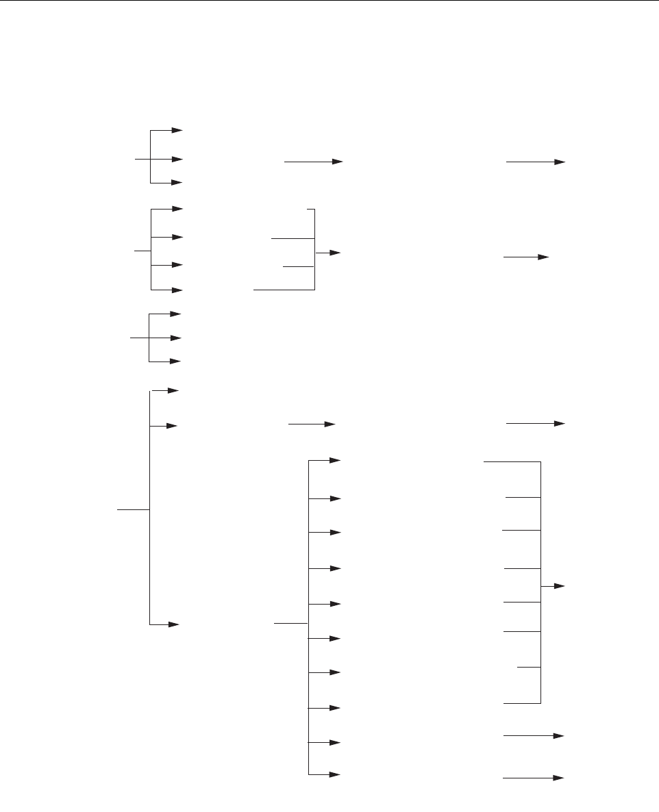
Table 4-4. Host Unit Fault/Alarm Isolation Diagram, continued
Fwd/Rev
(Port 1/Port 2)
See Table 4-5
Problem E
See Table 4-5
Problem E
Green - Normal
Red - Major Alarm
Pri Rx Light - No light received
over optical reverse path
Pri Rx Errors - Excessive errors
received over optical reverse path
See specific
fault indicator
See specific
fault indiator
Minor Contact Output - Minor alarm
reported by HU or STM
Major Contact Output - Major alarm
reported by HU or STM
Remote Lost - The HU cannot
communicate with remote (STM)
EMS Link Status - The EMS cannot
communicate with HU
No Associated LED
See Table 4-5
Problem E
See Table 4-5
Problem F
20014-A
Remote
Unit
Green - Normal
Yellow - Minor Alarm at Remote Unit - See Table 4-6. Remote Unit Fault/Alarm Isolation Diagram
Red - Major Alarm at Remote Unit - See Table 4-6. Remote Unit Fault/Alarm Isolation Diagram
Drive
851-869
Green - Normal
Yellow - Minor Alarm
Red - Major Alarm
RF Underdrive - 800 MHz forward
path RF signal level too low
RF Overdrive - 800 MHz forward
path RF signal level too high
Table 4-5
Problem C
Table 4-5
Problem D
Drive
935-940
Green - Normal
Yellow - Minor Alarm
Red - Major Alarm
RF Underdrive 900 MHz - 900 MHz
forward path RF signal level too low
RF Overdrive 900 MHz - 900 MHz
forward path RF signal level too high
Table 4-5
Problem C
Table 4-5
Problem D

ADCP-75-179 • Preliminary Issue A • September 2004 • Section 4: maintenance
Page 4-9
© 2004, ADC Telecommunications, Inc.
3.2 STM Troubleshooting
Use this section to troubleshoot alarms that originate with the STM. When a Minor alarm
occurs, one (or more) of the STM LED’s will turn yellow and the EMS software will indicate a
minor fault/alarm. When a Major alarm occurs, one (or more) of the STM LED’s will turn red
and the EMS software will indicate a major fault/alarm. Locate the LED and the corresponding
fault/status indicator in Table 4-6 and then take the corrective action indicated.
PROBLEM C: The RF input signal level is below the underdrive threshold.
POSSIBLE CAUSE CORRECTIVE ACTION/COMMENTS
1. Composite output signal from EBTS is too low.
2. Faulty coaxial connection between the HU
and the EBTS.
3. Incorrect attenuation in forward path RF
coaxial link.
1. Check EBTS composite output signal level and
adjust if too low.
2. Correct EBTS cables if faulty.
3. Check Host Forward Attenuator setting and
adjust if attenuation is too high.
PROBLEM D: The RF input signal is above the overdrive threshold.
POSSIBLE CAUSE CORRECTIVE ACTION/COMMENTS
1. Composite output signal level from EBTS is
too high.
2. Incorrect attenuation in forward path RF
coaxial link.
1. Check EBTS composite output signal level and
adjust if too high.
2. Check Forward Attenuator setting and adjust if
attenuation is too low.
PROBLEM E: No light received over the reverse path or excessive errors received over the reverse path
POSSIBLE CAUSE CORRECTIVE ACTION/COMMENTS
1. Faulty reverse path optical fiber.
2. Faulty optical transmit port at the STM;
or faulty optical receive port at the HU
1. Test optical fiber. Clean connector if dirty. Repair
or replace optical fiber if faulty. (See Section 4.1).
2. Test optical ports. Replace HU or STM if port is
faulty (See Section 4.2).
PROBLEM F: The HU does not respond to control or monitoring commands sent by the EMS.
POSSIBLE CAUSE CORRECTIVE ACTION/COMMENTS
1. The HU is not powered.
2. The cable connection between the HU and the
EMS computer is faulty.
3. The CAN cable connections between the HUs
in a multiple HU installation are faulty.
1. See Problem A this table.
2. Inspect EMS cable and repair or replace if faulty.
3. Inspect each CAN cable and repair or replace if
faulty.
Table 4-5. Host Unit Fault/Alarm Corrective Action, continued
ADCP-75-179 • Preliminary Issue A • September 2004 • Section 4: maintenance
Page 4-10
© 2004, ADC Telecommunications, Inc.
Table 4-6. Remote Unit Fault/Alarm Isolation Diagram
AC
Power
Remote Unit Front Panel LED
Green - Powered by AC power
source
Red - Major Alarm
Off - Not powered
Software Fault/Status Indicator
Host
Unit
Green - Normal
Yellow - Minor Alarm at Host Unit - See Table 4-4. Host Unit Fault/Alarm Isolation Diagram
Red - Major Alarm at Host Unit - See Table 4-4. Host Unit Faul/Alarm Isolation Diagram
STM
Green - Normal
Yellow - Minor Alarm
Red - Major Alarm
Temperature - Over temperature
Replace STM
See Table 4-7
Problem B
Replace HU or
STM with
correct unit
Corrective Action
or Reference
Converter - Power supply
converter failure
LO Synth Lock - Local
oscillator synthesizer out of lock
Pri Rev Synth Lock - Reverse
primary synthesizer out of lock
Ref Synth Lock - Reference
synthesizer out of lock
8 Volt - Onboard 8 Volt power
supply below threshold
3.8 Volt - Onboard 3.8 Volt power
supply below threshold
Pri Rev Mux Lock - Reverse primary
phase locked loop out-of-lock
Pri Laser Fail - Reverse primary
laser failure
Hardware mismatch - Host and
Remote band mismatch
Battery Voltage - Battery
voltage below threshold
AC Fail - The AC power is off,
RU powered by back-up battery
See Table 4-7
Problem A
See battery
manual
Standby
Green blinking - Standby
Yellow blinking -
Program load
Red blinking - Test
Off - Normal
Oper Mode - Operational mode
of system
Use EMS to
change system to
required mode
Continued
20015-A
ADCP-75-179 • Preliminary Issue A • September 2004 • Section 4: maintenance
Page 4-11
© 2004, ADC Telecommunications, Inc.
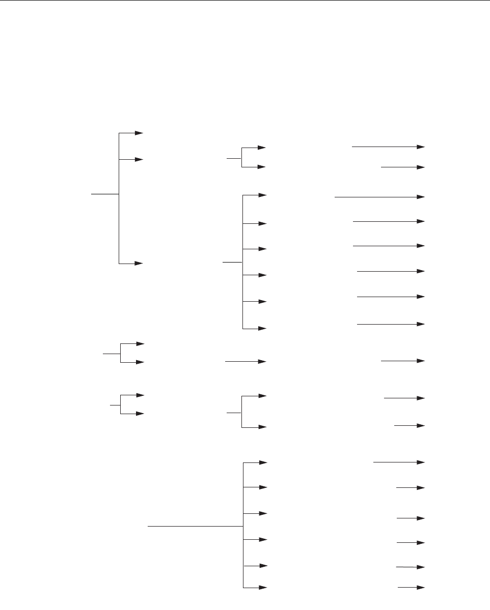
Remote Unit Front Panel LED Software Fault/Status Indicator Corrective Action
or Reference
Fwd/Rev
(Port 1/Port 2)
See Table 4-7
Problem E
See Table 4-7
Problem E
Green - Normal
Red - Major Alarm
Pri Rx Light - No light received
over optical forward path
Pri Errors - Excessive errors
received over optical forward path
PA
Green - Normal
Yellow - Minor Alarm
Red - Major Alarm
Install LPA
Check LPA. See
Table 4-8
Check LPA. See
Table 4-8
Check LPA. See
Table 4-8
Check LPA. See
Table 4-8
Check LPA. See
Table 4-8
LPA Detect - LPA
not installed
LPA Over Power - LPA
signal level too high
LPA VSWR - The LPA
VSWR is too high
LPA DC Fail - LPA DC
power supply failure
LPA Loop Failed - LPA
internal loop failure
LPA Low Power - LPA
internal amplifier failure
LPA Fan - Fan failure
LPA Temp - Over temperature
Replace
LPA fan
See Table 4-7
Problem C
VSWR
Green - Normal
Red - Major Alarm System VSWR - The VSWR at
the quadraplexer is too high
See Table 4-7
Problem D
Host Lost - The STM cannot
communicate with Host (HU)
EMS Link Status - The EMS cannot
communicate with STM
Minor Extern Input - Minor external
alarm reported by STM
Major Extern Input - Major external
alarm reported by STM
RF Power - No RF power detected
at quadraplexer (STM)
LPA Disable - The LPA is shut down
No Associated LED
See Table 4-7
Problem G
See Table 4-7
Problem G
See Table 4-7
Problem H
See Table 4-7
Problem F
See Table 4-7
Problem E
Check LPA. See
Table 4-8
Table 4-6. Remote Unit Fault/Alarm Isolation Diagram, continued
20016-A

ADCP-75-179 • Preliminary Issue A • September 2004 • Section 4: maintenance
Page 4-12
© 2004, ADC Telecommunications, Inc.
Table 4-7. STM Fault/Alarm Corrective Action
PROBLEM A: The RU is powered by the battery back-up system.
POSSIBLE CAUSE CORRECTIVE ACTION/COMMENTS
1. The AC power system circuit breaker is open
or the AC power has failed.
2. The STM has failed.
1. Check the AC power system, repair as needed,
and reset circuit breaker.
2. Replace the STM.
PROBLEM B: The STM is overheating.
POSSIBLE CAUSE CORRECTIVE ACTION/COMMENTS
1. Air intake or exhaust opening to the remote
unit cabinet is blocked
2. Ambient temperature > 50º C/122º F.
3. Faulty fan.
4. The STM has failed.
1. Remove cause of air-flow blockage.
2. Reduce ambient temperature.
3. Replace STM fan (See applicable manual).
4. Replace STM.
PROBLEM C: The LPA is overheating.
POSSIBLE CAUSE CORRECTIVE ACTION/COMMENTS
1. Air intake or exhaust opening to the remote
unit cabinet is blocked
2. Ambient temperature > 50º C/122º F.
3. Faulty fan.
1. Remove cause of air-flow blockage.
2. Reduce ambient temperature.
3. Replace LPA fan (See applicable manual).
PROBLEM D: The forward path VSWR is above threshold.
POSSIBLE CAUSE CORRECTIVE ACTION/COMMENTS
1. Faulty antenna or antenna system.
2. Faulty antenna cable.
3. The STM qudraplexer has failed.
1. Check the antenna system for shorts or opens
(including lightning protector).
2. Check the antenna cable for faulty connections.
3. Replace the STM.
PROBLEM E: No light received over the forward path or excessive errors received over the forward path
POSSIBLE CAUSE CORRECTIVE ACTION/COMMENTS
1. Faulty forward path optical fiber.
2. Faulty optical transmit port at the HU;
or faulty optical receive port at the STM.
1. Test optical fiber. Clean connector if dirty. Repair
or replace optical fiber if faulty. (See Section 4.1).
2. Test optical ports. Replace HU or STM if port is
faulty (see Section 4.2).
PROBLEM F: The STM does not respond to control or monitoring commands sent by the EMS.
POSSIBLE CAUSE CORRECTIVE ACTION/COMMENTS
1. The cable connection between the STM and
the EMS computer is faulty. 1. Inspect EMS cable and repair or replace if faulty.
PROBLEM G: An external fault is detected at the Remote Unit.
POSSIBLE CAUSE CORRECTIVE ACTION/COMMENTS
1. The RU cabinet door is open.
2. Customer specified external fault at RU
1. Close RU cabinet door.
2. Check RU and correct specified external fault.

ADCP-75-179 • Preliminary Issue A • September 2004 • Section 4: maintenance
Page 4-13
© 2004, ADC Telecommunications, Inc.
3.3 LPA Troubleshooting
During normal operation of the 35 Watt LPA, all LED’s should be Off. When troubleshooting
the LPA, always check the LPA front panel display for messages before initiating a reset or
replacing the LPA. The display will generally indicate the reason for the alarm.
Table 4-8. 35 Watt LPA Fault Isolation and Corrective Action
LED: FAIL Color: Yellow Alarm Type: Major
PROBLEM: Internal fault detected in the LPA.
POSSIBLE CAUSE CORRECTIVE ACTION/COMMENTS
1. The STM to LPA connecting cable is faulty.
2. The LPA has failed.
1. Inspect cable and repair or replace if faulty.
2. Replace LPA
LED: SHUTDOWN Color: Red Alarm Type: Major
PROBLEM: The RF output from the LPA is shutdown.
POSSIBLE CAUSE CORRECTIVE ACTION/COMMENTS
1.The RF ON/OFF switch is in the OFF position
2. The LPA is in the forced shutdown mode
(single front fan unit) or internal shutdown
mode (dual front fan unit).
3. Breaker switch on LPA is open
4. The LPA is faulty.
1. Place RF ON/OFF switch in the ON position
2. Watch the LED Display and note reason for the
forced shutdown. Refer to the Display Message
section of this table for the recommended correc-
tive action.
3. Reset breaker switch.
4. Replace LPA.
DISPLAY MESSAGE FORCED/INTERNAL SHUTDOWN Alarm Type: LOOP FAIL
PROBLEM: Internal fault detected in the LPA.
POSSIBLE CAUSE CORRECTIVE ACTION/COMMENTS
1. The LPA has failed. 1. Replace LPA
DISPLAY MESSAGE FORCED/INTERNAL SHUTDOWN Alarm Type: DC FAIL
PROBLEM: Internal fault detected in the LPA.
POSSIBLE CAUSE CORRECTIVE ACTION/COMMENTS
1. The LPA has failed. 1. Replace LPA
DISPLAY MESSAGE FORCED/INTERNAL SHUTDOWN Alarm Type: LOW POWER ALARM
PROBLEM: Internal fault detected in the LPA.
POSSIBLE CAUSE CORRECTIVE ACTION/COMMENTS
1. The LPA has failed. 1. Replace LPA
DISPLAY MESSAGE FORCED/INTERNAL SHUTDOWN Alarm Type: FANFAIL
PROBLEM: Internal fault detected in the LPA.
POSSIBLE CAUSE CORRECTIVE ACTION/COMMENTS
1. Both LPA fans have failed. 1. Replace both LPA fans. To reset, use EMS to
place Digivance system in standby mode and
then place system back in normal mode.

ADCP-75-179 • Preliminary Issue A • September 2004 • Section 4: maintenance
Page 4-14
© 2004, ADC Telecommunications, Inc.
DISPLAY MESSAGE FORCED/INTERNAL SHUTDOWN Alarm Type: OVER POWER ALARM
PROBLEM: Output power from the LPA exceeds the maximum rating.
POSSIBLE CAUSE CORRECTIVE ACTION/COMMENTS
1. The power level of the RF forward path
composite input signal at the HU is too high.
2. The LPA has failed.
1. Check the power level of the RF composite input
signal at the HU and adjust to correct level. To
reset, use EMS to place Digivance system in
standby mode and then place system back in
normal mode.
2. Replace LPA.
DISPLAY MESSAGE FORCED/INTERNAL SHUTDOWN Alarm Type: VSWR ALARM
PROBLEM: The VSWR exceeds threshold setting of 3:1.
POSSIBLE CAUSE CORRECTIVE ACTION/COMMENTS
1. The interface cable between the LPA and STM
is faulty or the interface cable connectors are
faulty.
2. The antenna cable or antenna cable connectors
are faulty.
3. The antenna or antenna system is faulty.
4.The STM qudraplexer has failed.
5. The LPA has failed.
1. Inspect interface cable and connectors and repair
or replace as needed.To reset, use EMS to place
Digivance system in standby mode and then place
system back in normal mode.
2. Inspect antenna cable and connectors and repair
or replace as needed.To reset, use EMS to place
Digivance system in standby mode and then place
system back in normal mode.
3. Check the antenna circuit for shorts or opens
(including lightning protector). To reset, use EMS
to place Digivance system in standby mode and
then place system back in normal mode.
4. Replace STM.
5. Replace LPA
Table 4-8. 35 Watt LPA Fault Isolation and Corrective Action, continued

ADCP-75-179 • Preliminary Issue A • September 2004 • Section 4: maintenance
Page 4-15
© 2004, ADC Telecommunications, Inc.
4 TEST PROCEDURES
This section provides procedures for common troubleshooting and maintenance tests. Refer to
these procedures as needed when specified in the Fault/Alarm Isolation Diagrams in Section 3.
4.1 Optical Power Test
A break in an optical fiber or a fault with the optical connector will interrupt communications
between linked components or generate excessive errors. Use the following procedure to isolate
a problem with an optical fiber or connector.
1. Put on the IR filtering safety glasses.
2. Notify the NOC or alarm monitoring system operator that the system is going offline.
3. At the HU and at the STM, place the On/Off switches in the OFF position (press O).
4. Disconnect the optical fiber connectors for the fiber to be tested at the HU and the STM.
5. Inspect the optical connectors. Verify that connectors are clean and that no scratches or
imperfections are visible on the fiber end. Clean and polish the optical connectors if necessary.
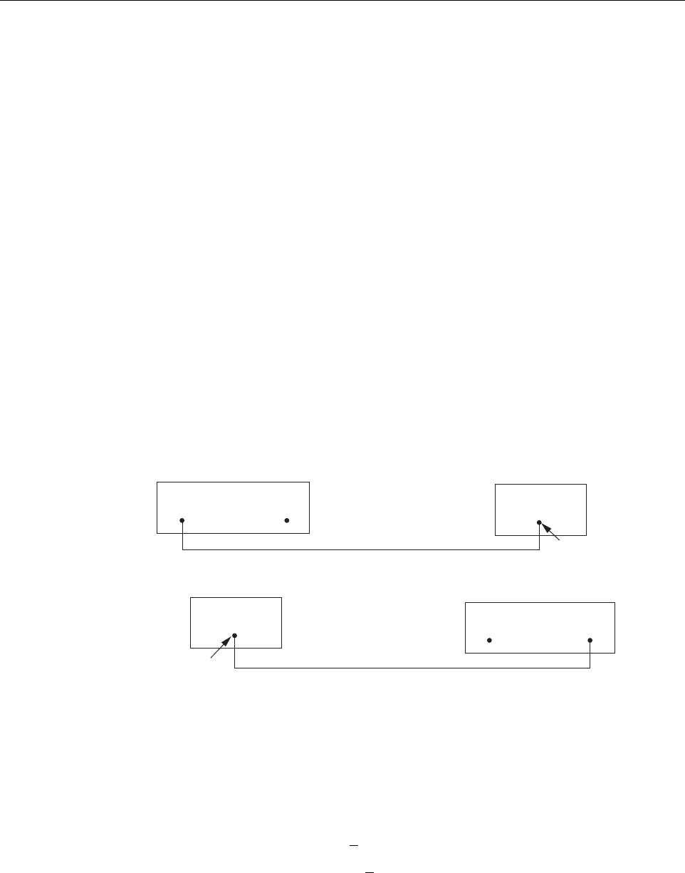
6. Connect the optical power meter to the output (receiver) end of the optical fiber as shown
in Figure 4-2. If an attenuator was included in the fiber link, make sure the attenuator is
installed.
Figure 4-2. Forward and Reverse Path Optical Fiber Test Set Up
Danger: This equipment uses a Class 1 Laser according to FDA/CDRH rules. Laser radiation
can seriously damage the retina of the eye. Do not look into the ends of any optical fiber. Do not
look directly into the optical transmitter of any unit or exposure to laser radiation may result.
An optical power meter should be used to verify active fibers. A protective cap or hood MUST
be immediately placed over any radiating transmitter or optical fiber connector to avoid the
potential of dangerous amounts of radiation exposure. This practice also prevents dirt particles
from entering the connector.
Note: Turning off the HU and STM disables the respective lasers which is necessary in
order to safely inspect and clean the optical connectors.
HOST UNIT
FWD
(PORT 1)
REV
(PORT 2)
FWD
(PORT 1)
REV
(PORT 2)
STM
OPTICAL POWER
METER
OPTICAL POWER
METER
ATTENUATOR
(IF USED)
ATTENUATOR
(IF USED)
FORWARD PATH
OPTICAL FIBER
REVERSE PATH
PATH OPTICAL FIBER
-13 TO -25 dBm
-15 TO -25 dBm
FORWARD PATH OPTICAL FIBER
TEST SET UP
REVERSE PATH
OPTICAL FIBER TEST SET UP
20017-A
ADCP-75-179 • Preliminary Issue A • September 2004 • Section 4: maintenance
Page 4-16
© 2004, ADC Telecommunications, Inc.
7. Connect the input (transmitter) end of the optical fiber to the transmitting HU or STM
(see Figure 4-2).
8. At the transmitting HU or STM, place the On/Off switch in the ON position (press I).
9. Using the transmitting HU or STM as an optical light source, measure the optical power
at the receiver end of the optical fiber. The power level of the optical input signal at the
HU or STM must fall within the following ranges:
Forward Path Signal at the STM: –15 to –25 dBm (with attenuator installed)
Reverse Path Signal at the HU: –13 to –25 dBm (with attenuator installed)
If the power level of the received optical signal is within the specified range, the optical
fiber and the far end unit are good. If the power level of the received signal is not with
the specified range, either the optical fiber is faulty or the far end unit optical transmitter
is faulty. Continue with test procedure to isolate the problem
10. At the transmitting HU or STM, place the On/Off switch in the OFF position (press O).
11. Disconnect the optical power meter from the receiver end of the optical fiber.
12. Use a 1 meter patch cord to connect the optical power meter to the transmitting HU or
STM as shown in Figure 4-3.
Figure 4-3. Host Unit and STM Optical Transmitter Test Set Up
13. At the transmitting HU or STM, place the On/Off switch in the ON position (press I).
14. Measure the optical output power of the transmitting HU or STM. The power level of the
optical output signal from the HU or STM must meet the following specification:
Forward Path Signal at the HU: 0 + 1 dBm
Reverse Path Signal at the STM: +2 + 1 dBm
If the power level of the optical output signal is within specifications with a 1 meter
patch cord installed, the fiber optic link is faulty. If the power level of the optical signal
is not within specifications, the far end HU or STM optical transmitter is faulty.
HOST UNIT
STM
OPTICAL POWER
METER
OPTICAL POWER
METER
+2 +/- 1 dBm
0 +/- 1 dBm
HOST UNIT OPTICAL TRANSMITTER
TEST SET UP
STM OPTICAL TRANSMITTER
TEST SET UP
1 METER PATCH CORD
1 METER PATCH CORD
20018-A
FWD
(PORT 1)
REV
(PORT 2)
FWD
(PORT 1)
REV
(PORT 2)

ADCP-75-179 • Preliminary Issue A • September 2004 • Section 4: maintenance
Page 4-17
© 2004, ADC Telecommunications, Inc.
15. At the transmitting HU or STM, place the On/Off switch in the OFF position (press O).
16. Disconnect the optical power meter from the receiver end of the optical fiber.
17. Reconnect the optical fibers to the receiving HU or STM.
18. Repeat steps 3 through 17 for each optical fiber that requires testing.
19. When ready to put the system back into service, place the On/Off switch in the ON
position (press I) at both the HU and STM.
20. Notify the NOC or alarm monitoring service that the system is going back online.
4.2 Optical Loopback Test
The following procedures provide tests to determine if an optical port fault exists with the Host
Unit or with the STM.
1. Put on the IR filtering safety glasses.
2. Notify the NOC or alarm monitoring system operator that the system is going offline.
3. At the HU or STM (whichever unit is being tested), place the On/Off switch in the OFF
position (press O).
4. Disconnect the optical fiber connectors from the FWD (PORT 1) and REV (PORT 2)
optical ports and place a dust cap over each connector.
5. Plug a 15 dB in-line optical attenuator into the FWD (PORT 1) optical port as shown in
Figure 4-4.
Figure 4-4. Host Unit and STM Loopback Test
Danger: This equipment uses a Class 1 Laser according to FDA/CDRH rules. Laser radiation
can seriously damage the retina of the eye. Do not look into the ends of any optical fiber. Do not
look directly into the optical transmitter of any unit or exposure to laser radiation may result.
An optical power meter should be used to verify active fibers. A protective cap or hood MUST
be immediately placed over any radiating transmitter or optical fiber connector to avoid the
potential of dangerous amounts of radiation exposure. This practice also prevents dirt particles
from entering the connector.
HOST UNIT OR STM
1 METER PATCH CORD
15 dB
ATTENUATOR
20019-A
FWD
(PORT 1)
REV
(PORT 2)

ADCP-75-179 • Preliminary Issue A • September 2004 • Section 4: maintenance
Page 4-18
© 2004, ADC Telecommunications, Inc.
6. Connect a 1 meter patch cord between the optical attenuator and the REV (PORT 2)
optical port.
7. Place the On/Off switch in the ON position (press I) and observe the FWD/REV (PORT 1/
PORT 2) LED indicator.
8. The FWD/REV (PORT 1/PORT 2) LED indicator will turn either red or green. If the LED
turns red, either the FWD (PORT 1) optical transmitter or the REV (PORT 2) receiver is
faulty. If the LED turns green, both the FWD (PORT 1) and the REV (PORT 2) optical
ports are good.
9. Place the On/Off switch in the OFF position (press O).
10. Remove the dust caps from the optical fiber connectors.
11. Clean each connector (follow connector supplier’s recommendations) and then insert each
connector into the appropriate optical port.
12. When ready to put the unit back into service, place the On/Off switch in the ON position
(press I).
13. Notify the NOC or alarm monitoring service that the system is going back online.

ADCP-75-179 • Preliminary Issue A • September 2004 • Section 4: maintenance
Page 4-19
© 2004, ADC Telecommunications, Inc.
5 SCHEDULED MAINTENANCE REQUIREMENTS
Table 4-9 specifies the system maintenance requirements and the recommended maintenance
interval for each maintenance task. Refer to the manual specified in the table for the required
maintenance procedure.
Table 4-9. Scheduled Maintenance
INTERVAL ITEM REQUIREMENT
1 month Battery* Check float voltage.
Check system ambient temperature.
Check system float current.
6 months Battery* Perform 1 month scheduled maintenance tasks.
Check individual battery terminal temperature.
Check individual battery float voltages.
12 months Battery *
RU cabinet filter**
Perform 1 and 6 month scheduled maintenance tasks
Complete detailed physical inspection.
Re-torque terminal connections.
Perform general system maintenance.
Perform cabinet maintenance.
Remove and clean the RU cabinet filter. Refer to the appro-
priate Remote Unit Installation and Maintenance Manual (see
Related Manuals section) for the required procedures.
24 months Battery* Perform 1, 6, and 12 month scheduled maintenance tasks.
Test battery system for rated capacity.
60 months HU Fans
STM Fan
LPA Fans
Remove and replace the cooling fans in the HU, STM, and
LPA. Refer to the appropriate Installation and Maintenance
Manual (see Related Manuals section) for the required proce-
dures.
* Refer to the PRC-SERIES OPERATING AND FIELD SERVICE MANUAL (provided with the
back-up battery system) for the specified battery maintenance procedures.
**Though it is not recommended that the RU be installed in a salt-air environment, if done so, clean the
cabinet filter on a monthly basis instead of on a 12 month basis. In addition, the RU should be
inspected for corrosion due to salt, particularly near the fans and around the connectors. The MTBF of
the RU may be impacted if the RU is exposed to salt-air.

ADCP-75-179 • Preliminary Issue A • September 2004 • Section 4: maintenance
Page 4-20
© 2004, ADC Telecommunications, Inc.
Blank

ADCP-75-179 • Preliminary Issue A • September 2004 • Section 5: General Information
Page 5-1
© 2004, ADC Telecommunications, Inc.
SECTION 5: GENERAL INFORMATION
1 WARRANTY/SOFTWARE . . . . . . . . . . . . . . . . . . . . . . . . . . . . . . . . . . . . . . . . . . . . . . . . . . . . . . . . . . . . . . . . . .5-1
2 SOFTWARE SERVICE AGREEMENT. . . . . . . . . . . . . . . . . . . . . . . . . . . . . . . . . . . . . . . . . . . . . . . . . . . . . . . . . . .5-1
3 REPAIR/EXCHANGE POLICY . . . . . . . . . . . . . . . . . . . . . . . . . . . . . . . . . . . . . . . . . . . . . . . . . . . . . . . . . . . . . . .5-1
4 REPAIR CHARGES . . . . . . . . . . . . . . . . . . . . . . . . . . . . . . . . . . . . . . . . . . . . . . . . . . . . . . . . . . . . . . . . . . . . . .5-2
5 REPLACEMENT/SPARE PRODUCTS . . . . . . . . . . . . . . . . . . . . . . . . . . . . . . . . . . . . . . . . . . . . . . . . . . . . . . . . . .5-2
6 RETURNED MATERIAL . . . . . . . . . . . . . . . . . . . . . . . . . . . . . . . . . . . . . . . . . . . . . . . . . . . . . . . . . . . . . . . . . . .5-2
7 CUSTOMER INFORMATION AND ASSISTANCE . . . . . . . . . . . . . . . . . . . . . . . . . . . . . . . . . . . . . . . . . . . . . . . . . . .5-3
_________________________________________________________________________________________________________
1 WARRANTY/SOFTWARE
The Product and Software warranty policy and warranty period for all ADC Products is
published in ADC’s Warranty/Software Handbook. Contact the Technical Assistance Center at
1-800-366-3891, extension 73476 (in U.S.A. or Canada) or 952-917-3476 (outside U.S.A. and
Canada) for warranty or software information or for a copy of the Warranty/Software
Handbook.
2 SOFTWARE SERVICE AGREEMENT
ADC software service agreements for some ADC Products are available at a nominal fee.
Contact the Technical Assistance Center at 1-800-366-3891, extension 73476 (in U.S.A. or
Canada) or 952-917-3476 (outside U.S.A. and Canada) for software service agreement
information.
3 REPAIR/EXCHANGE POLICY
All repairs of ADC Products must be done by ADC or an authorized representative. Any
attempt to repair or modify ADC Products without written authorization from ADC voids the
warranty.
If a malfunction cannot be resolved by the normal troubleshooting procedures, call the
Technical Assistance Center at 1-800-366-3891, extension 73476 (in U.S.A. or Canada) or
952-917-3476 (outside U.S.A. and Canada). A telephone consultation can sometimes resolve a
problem without the need to repair or replace the ADC Product.
If, during a telephone consultation, ADC determines the ADC Product needs repair, ADC will
authorize the return of the affected Product for repair and provide a Return Material
Authorization number and complete return shipping instructions. If time is critical, ADC can
arrange to ship the replacement Product immediately. In all cases, the defective Product must be
carefully packaged and returned to ADC.
Content Page

ADCP-75-179 • Preliminary Issue A • September 2004 • Section 5: General Information
Page 5-2
© 2004, ADC Telecommunications, Inc.
4 REPAIR CHARGES
If the defect and the necessary repairs are covered by the warranty, and the applicable warranty
period has not expired, the Buyer’s only payment obligation is to pay the shipping cost to return
the defective Product. ADC will repair or replace the Product at no charge and pay the return
shipping charges.
Otherwise, ADC will charge a percentage of the current Customer Product price for the repair
or NTF (No Trouble Found). If an advance replacement is requested, the full price of a new unit
will be charged initially. Upon receipt of the defective Product, ADC will credit Buyer with 20
percent of full price charged for any Product to be Out-of-Warranty. Products must be returned
within thirty (30) days to be eligible for any advance replacement credit. If repairs necessitate a
visit by an ADC representative, ADC will charge the current price of a field visit plus round trip
transportation charges from Minneapolis to the Buyer’s site.
5 REPLACEMENT/SPARE PRODUCTS
Replacement parts, including, but not limited to, button caps and lenses, lamps, fuses, and patch
cords, are available from ADC on a special order basis. Contact the Technical Assistance Center
at 1-800-366-3891, extension 73476 (in U.S.A. or Canada) or 952-917-3476 (outside U.S.A.
and Canada) for additional information.
Spare Products and accessories can be purchased from ADC. Contact Sales Administration at
1-800-366-3891, extension 73000 (in U.S.A. or Canada) or 1-952-938-8080 (outside U.S.A.
and Canada) for a price quote and to place your order.
6 RETURNED MATERIAL
Contact the ADC Product Return Department at 1-800-366-3891, extension 73748 (in U.S.A. or
Canada) or 952-917-3748 (outside U.S.A. and Canada) to obtain a Return Material
Authorization number prior to returning an ADC Product.
All returned Products must have a Return Material Authorization (RMA) number clearly
marked on the outside of the package. The Return Material Authorization number is valid for 90
days from authorization.
Page 5-3
ADCP-75-179 • Preliminary Issue A • September 2004 • Section 5: General Information
7 CUSTOMER INFORMATION AND ASSISTANCE
© 2004, ADC Telecommunications, Inc.
All Rights Reserved
Printed in U.S.A .
13944-L
WRITE:
ADC TELECOMMUNICATIONS, INC
PO BOX 1101,
MINNEAPOLIS, MN 55440-1101, USA
ADC TELECOMMUNICATIONS (S'PORE) PTE. LTD.
100 BEACH ROAD, #18-01, SHAW TOWERS.
SINGAPORE 189702.
ADC EUROPEAN CUSTOMER SERVICE, INC
BELGICASTRAAT 2,
1930 ZAVENTEM, BELGIUM
PHONE:
EUROPE
Sales Administration: +32-2-712-65 00
Technical Assistance: +32-2-712-65 42
EUROPEAN TOLL FREE NUMBERS
UK: 0800 960236
Spain: 900 983291
France: 0800 914032
Germany: 0180 2232923
U.S.A. OR CANADA
Sales: 1-800-366-3891 Extension 73000
Technical Assistance: 1-800-366-3891
Connectivity Extension 73475
Wireless Extension 73476
ASIA/PACIFIC
Sales Administration: +65-6294-9948
Technical Assistance: +65-6393-0739
ELSEWHERE
Sales Administration: +1-952-938-8080
Technical Assistance: +1-952-917-3475
Italy: 0800 782374
PRODUCT INFORMATION AND TECHNICAL ASSISTANCE:
Contents herein are current as of the date of publication. ADC reserves the right to change the contents without prior notice.
In no event shall ADC be liable for any damages resulting from loss of data, loss of use, or loss of profits and ADC further
disclaims any and all liability for indirect, incidental, special, consequential or other similar damages. This disclaimer of
liability applies to all products, publications and services during and after the warranty period. This publication may be
verified at any time by contacting ADC's Technical Assistance Center.
euro_tac@adc.com
asiapacific_tac@adc.com
wireless.tac@adc.com
connectivity_tac@adc.com
Blank

i
www.adc.com