ADC Telecommunications DLCSMR3D Digivance LRCS SMR Dual Band System User Manual 75179
ADC Telecommunications Inc Digivance LRCS SMR Dual Band System 75179
Contents
- 1. manual1
- 2. manual2
- 3. manual3
manual2

ADCP-75-179 • Preliminary Issue A • September 2004 • Section 2: Description
Page 2-12
© 2004, ADC Telecommunications, Inc.
Table 2-2. Typical Spectrum Transport Module User Interface
REF
NO
USER INTERFACE
DESIGNATION DEVICE FUNCTIONAL
DESCRIPTION
1FWD
(PORT 1) SC connector
(single-mode) Input connection point for the forward path opti-
cal fiber.
2REV
(PORT 2) SC connector
(single-mode) Output connection point for the reverse path pri-
mary optical fiber.
3I/0 On/Off rocker
switch Provides AC power on/off control.
4 No designation 3-wire AC power
cord connector Connection point for the AC power cord.
5 No designation 2- wire DC power
cord connector Connection point for the back-up battery power
cord.
6 AUXILIARY DB-9 connector
(female) Connection point for the RS-232 auxiliary com-
munications interface cable.
7 SERVICE DB-9 connector
(female) Connection point for the RS-232 service inter-
face cable.
8 AC POWER Multi-colored LED
(green/red)
Indicates if the STM is powered by the AC power
source (green) or the back-up battery system
(red). See Note.
9 STANDBY Multi-colored LED
(green/yellow/red)
Indicates if the system is in the Normal state (off)
Standby state (blinking green), Test state (blink-
ing red), or Program Load state (blinking yel-
low). See Note.
10 HOST UNIT Multi-colored LED
(green/yellow/red)
Indicates if no alarms (green), a minor alarm
(yellow), or a major alarm (red) is reported by the
HU. See Note.
11 STM Multi-colored LED
(green/yellow/red)
Indicates if the STM is normal (green) or faulty
(red). See Note.
12 PA Multi-colored LED
(green/yellow/red)
Indicates if the power amplifier is normal
(green), over temperature (yellow), has a fan fail-
ure (yellow), is turned off (red), or faulty (red).
See Note.
13 VSWR Multi-colored LED
(green/yellow/red)
Indicates if the forward path VSWR is above
(red) or below (green) the fault threshold.
14 FWD/REV
(PORT 1/PORT 2) Multi-colored LED
(green/red)
Indicates if the forward path optical signal from
the HU are normal (green), if no signal is
detected (red), or errors are detected (red). See
Note.
15 ALARM IN MINOR
ALARM IN MAJOR
Screw-type terminal
connector (14–26
AWG)
Connection point for two external alarm inputs.
The door-open switch lead wires are typically
connected to the major alarm terminals.
16 ANTENNA N-type female RF
coaxial connector Connection point for the antenna.
Note: A more detailed description of LED operation is provided in Section 4.
ADCP-75-179 • Preliminary Issue A • September 2004 • Section 2: Description
Page 2-13
© 2004, ADC Telecommunications, Inc.
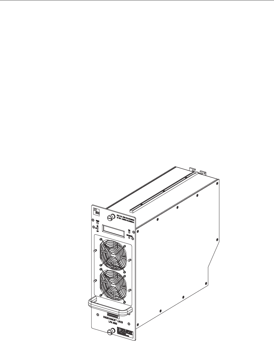
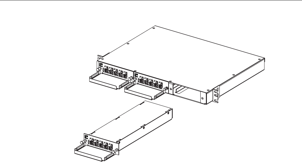
4 35 WATT LINEAR POWER AMPLIFIER
The 35 Watt Linear Power Amplifier (LPA), shown in Figure 2-5, works in conjunction with the
STM to amplify the forward path RF signal. The STM is interfaced with the LPA through the D-
sub connectors and wiring harness located at the rear of the RU outdoor cabinet or indoor
mounting shelf. The RF signal is passed to the LPA for amplification and then passed back to
the STM for filtering and output via the STM’s ANTENNA port. The STM also supplies DC
power to the LPA through the same interface.
4.1 Primary Components
The LPA consists of several electronic circuit board assemblies and two fan units that are
mounted within a powder-paint coated sheet metal enclosure. The metal enclosure provides a
mounting point for the electronic components and controls RF emissions. Except for the fan
units, the electronic components are not user replaceable. The LPA is designed for use with the
RU outdoor cabinets and the indoor mounting shelf. All controls, indicators, and switches are
mounted on the LPA front panel for easy access. A carrying handle is provided on the front of
the LPA to facilitate installation and transport.
Figure 2-5. 35 Watt Linear Power Amplifier Module
19731-B

ADCP-75-179 • Preliminary Issue A • September 2004 • Section 2: Description
Page 2-14
© 2004, ADC Telecommunications, Inc.
4.2 Mounting
The 35 Watt LPA mounts within the RU outdoor cabinets and the indoor mounting shelf.
Runners on the top and bottom of the LPA mesh with tracks within the cabinet or mounting
shelf. The runners and tracks guide the LPA into the installed position. The electrical interface
between the STM and LPA is supported by a D-sub female connector located on the rear side of
the LPA. A corresponding D-sub male connector mounted at the rear of the RU outdoor cabinet
or indoor mounting shelf mates with the LPA connector. Captive screws are provided for
securing the LPA in the installed position.
4.3 Fault Detection and Alarm Reporting
The 35 Watt LPA, in conjunction with the STM, detects and reports various faults including
power amplifier fault, output power fault, temperature fault, and fan fault. Various Light
Emitting Diode (LED) indicators, located on the front panel of the LPA, turn from green to red
or yellow if an LPA fault is detected. In addition, a digital display located on the LPA front
panel provides various fault messages. The status of the LPA, the alarm state (major or minor),
and other more detailed information is summarized and reported (by the STM) over the optical
interface to the HU and also to the service interface. This information may be accessed through
the EMS software GUI, the NOC/NEM interface, or the SNMP interface.
4.4 Powering
The LPA is powered by various DC voltages which are supplied by the STM over the electrical
interface provided by the D-sub connectors and wiring harness mounted within the RU outdoor
cabinet or indoor mounting shelf.
4.5 Cooling
Continuous air-flow for cooling is provided by a pair of fans. In the previous version of the LPA,
fans are mounted at the front and the rear side of the LPA housing. The front fan pulls cool air
into the module and the rear fan exhausts heated air out of the module. In the new version of the
LPA, two front mounted fans pull cool air into the module. The heated air is exhausted out the
back of the module. An alarm is provided that indicates if a high temperature condition (>50º C/
122º F) occurs or if a fan failure occurs. The fans may be field replaced if a failure occurs.
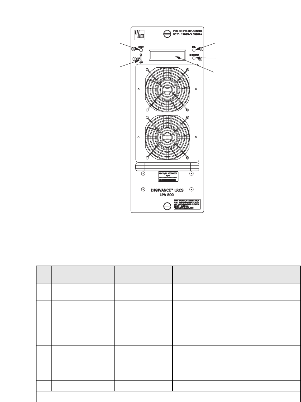
4.6 User Interface
The LPA user interface consists of the various LEDs, message displays, and switches that are
provided on the LPA front panel. The LPA user interface points are indicated in Figure 2-6 and
described in Table 2-3.
ADCP-75-179 • Preliminary Issue A • September 2004 • Section 2: Description
Page 2-15
© 2004, ADC Telecommunications, Inc.
Figure 2-6. Linear Power Amplifier User Interface (Typical)
Table 2-3. Linear Power Amplifier User Interface
REF
NO
USER INTERFACE
DESIGNATION DEVICE FUNCTIONAL
DESCRIPTION
1 RESET Momentary contact
push button switch Momentarily pressing the push button clears all
alarms and restarts the amplifier
2 RF ON OFF 2-position switch Placing the switch in the OFF position puts the LPA
in the standby state with RF output disabled. With
the switch off, the STM can not control the LPA
output power. Placing the switch in the ON position
puts the LPA in the normal state and allows the
STM to enable and disable the RF output.
3FAIL LED indicator
(yellow) Indicates the LPA is normal (off) or faulty
(yellow).
4 SHUTDOWN LED indicator (red) Indicates the LPA is in service (off) or shutdown
(red).
5 No designation Digital display Provides status and alarm messages. See Note.
Note: A more detailed description of the digital display messages is provided in Section 4.
19730-B
(1) RESET
SWITCH
(2) RF ON/OFF
SWITCH
(3) FAIL
LED
(4) SHUTDOWN
LED
(5) DIGITAL
DISPLAY
ADCP-75-179 • Preliminary Issue A • September 2004 • Section 2: Description
Page 2-16
© 2004, ADC Telecommunications, Inc.
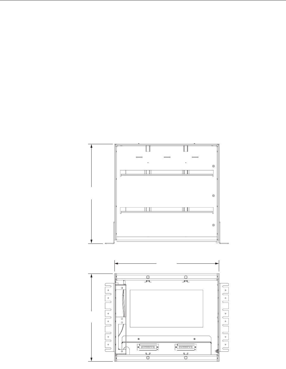
5 REMOTE UNIT MOUNTING SHELF
This section provides a brief description of the remote unit indoor mounting shelf. For complete
information, refer to the Installation and Maintenance Manual for the mounting shelf.
5.1 Indoor Mounting Shelf
The indoor mounting shelf, shown in Figure 2-7, is a rack-mountable frame assembly that
provides mounting slots for the STM, LPA, WDM (accessory), and CWDM (accessory)
modules plus connectors and a wiring harness for interfacing the STM and LPA modules. The
mounting shelf is designed for indoor installation in a 19- or 23-inch, EIA or WECO,
equipment rack. The frame assembly is constructed of aluminum and steel and is painted putty
white for corrosion protection. The indoor mounting shelf does not provide a mounting slot for
a back-up battery.
Figure 2-7. indoor Mounting Shelf
14.15 IN.
(359 MM)
16.06 IN.
(408 MM)
16.89 IN.
(429 MM)
TOP VIEW
FRONT VIEW 19008-A
ADCP-75-179 • Preliminary Issue A • September 2004 • Section 2: Description
Page 2-17
© 2004, ADC Telecommunications, Inc.
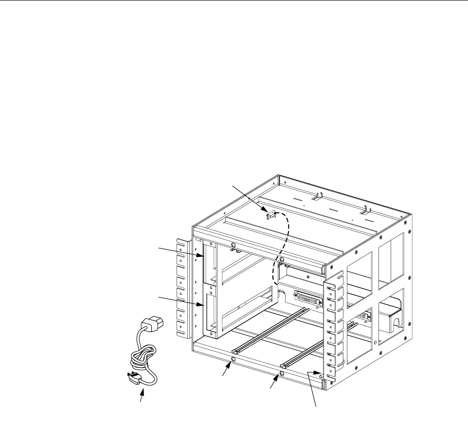
The AC power, fiber optic, and antenna cables route to the front of the indoor mounting shelf for
connection to the STM front panel. A lightning protector kit (accessory) is available separately
if lightning protection is required. A grounding lug is provided on the side of the mounting shelf
for connecting a grounding wire.
The indoor mounting shelf user interface consists primarily of the mounting slots and the AC
and DC power cables. The user interface points are shown in Figure 2-8. For additional
information, refer to the Digivance LRCS System Indoor Remote Unit Installation and
Maintenance Manual (ADCP-75-160).
Figure 2-8. indoor Mounting Shelf User Interface
6 SLIM-STYLE REMOTE UNIT CABINETS
This section provides a brief description of the slim-style remote unit cabinets. Four types of
slim-style cabinets are available. For complete information, refer to the Installation and
Maintenance Manual for the cabinet.
Each slim-style cabinet enclosure is constructed of heavy gauge aluminum and is painted putty
white for reduced solar loading and corrosion protection. Connection and entry points are
provided in the bottom of the enclosure for the antenna coaxial cables, fiber optic cable, and AC
power cable. Vent openings are provided in the bottom of the enclosure to permit air exchange
for cooling.
19009-A
(1) STM
MOUNTING
SLOT
(5) WDM
MOUNTING
SLOT
(2) LPA
MOUNTING
SLOT (3) GROUNDING
STUDS (INSIDE)
(6) CWDM
MOUNTING
SLOT
(7) CWDM DC
POWER CABLE
(4) AC POWER
CABLE
ADCP-75-179 • Preliminary Issue A • September 2004 • Section 2: Description
Page 2-18
© 2004, ADC Telecommunications, Inc.
The slim-style cabinet is weather-tight, but contact with salt-air mist should be avoided as it
may degrade the Mean Time Between Failure (MTBF) of the product. Drain hole openings in
the bottom of the cabinet allow any moisture that does enter the cabinet to drain out. The cabinet
door may be padlocked to prevent unauthorized entry. A door open switch is provided so that a
customer-selectable major or minor alarm is generated whenever the cabinet door is opened.
The slim-style cabinet can be mounted on a flat vertical surface, a pedestal, or from a utility
pole. A pedestal-mount kit (accessory) is available for pedestal-mount installations and a pole-
mount kit (accessory) is available for pole-mount installations. A grounding lug is provided on
the bottom of the cabinet for connecting a grounding wire.
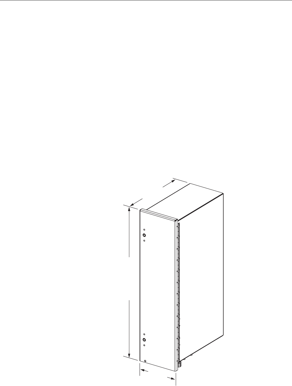
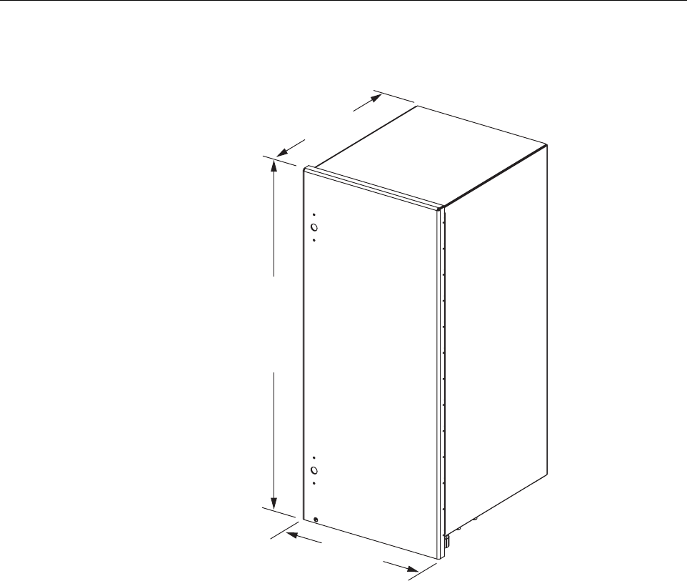
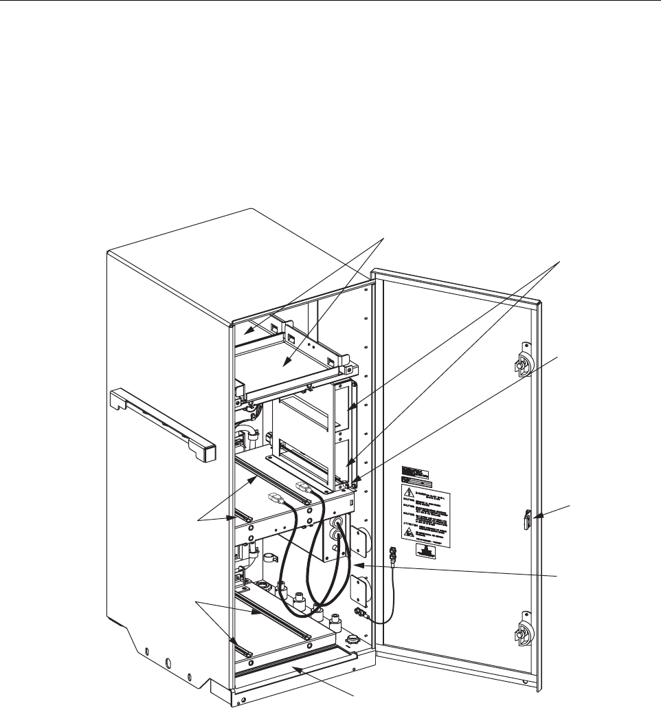
6.1 Slim-Style Single-STM Cabinet
The slim-style single-STM cabinet, shown in Figure 2-9, is a NEMA-3R enclosure (with
removable dust filter) that houses the remote modules and protects them from the environment.
The cabinet consists of the enclosure, mounting slots for the STM and LPA modules, an AC
power interface, a lightning protector, two fiber slack spools, and a mounting slot for a WDM or
CWDM (accessory) remote module.
Figure 2-9. Slim-Style Single-STM Cabinet
19400-B
12.0 IN
(305 MM)
20.7 IN
(526 MM)
40.4 INCHES
(1016 MM)
WITH BATTERY
31 INCHES
(787 MM)
W/O BATTERY
ADCP-75-179 • Preliminary Issue A • September 2004 • Section 2: Description
Page 2-19
© 2004, ADC Telecommunications, Inc.
On an optional basis, the cabinet is available either with or without a battery compartment. The
battery compartment version provides a mounting tray for a back-up battery. The slim-style
cabinet is designed for use in an outdoor environment but may be mounted indoors if required.
Opening the hinged door provides full access to the interior of the enclosure to facilitate module
and cable installation.
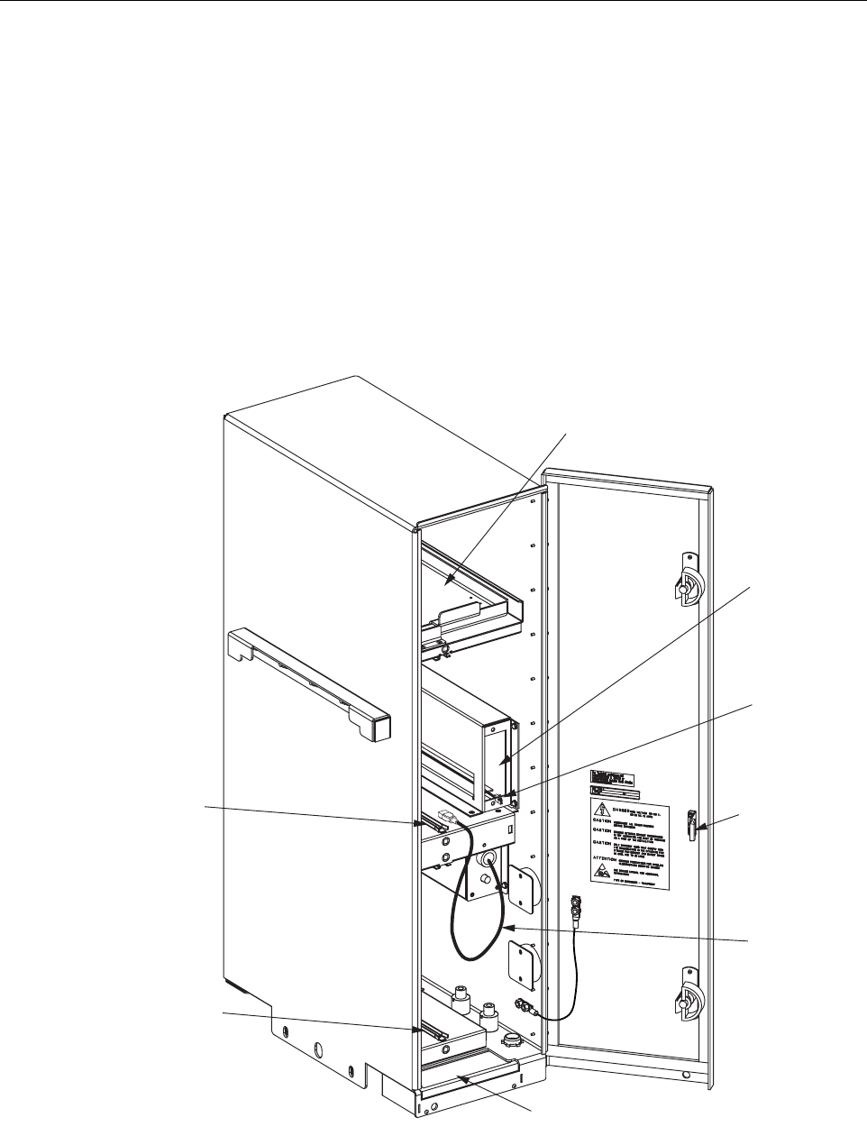
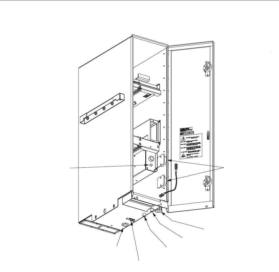
The slim-style single-STM cabinet user interface consists of the various connectors, fittings,
outlets, and switches that are provided on the interior and exterior of the enclosure. The user
interface points are indicated in Figure 2-10 and Figure 2-11. For additional information, refer
to the Digivance LRCS System Slim-Style Single-STM Remote Unit W/Battery Installation and
Maintenance Manual (ADCP-75-165); or the Digivance LRCS System Slim-Style Single-STM
Remote Unit Without Battery Installation and Maintenance Manual (ADCP-75-173).
Figure 2-10. Slim-Style Single-STM Cabinet User Interface - Top Front View
(7) DOOR
SWITCH
(8) AC
POWER CORD
(1) AIR INLET
FILTER
(3) STM
MOUNTING
SLOT
(2) LPA
MOUNTING
SLOT
(5) WDM/CWDM
MOUNTING SLOT
(4) BATTERY
TRAY
(6) CWDM
POWER CORD
19295-B
ADCP-75-179 • Preliminary Issue A • September 2004 • Section 2: Description
Page 2-20
© 2004, ADC Telecommunications, Inc.
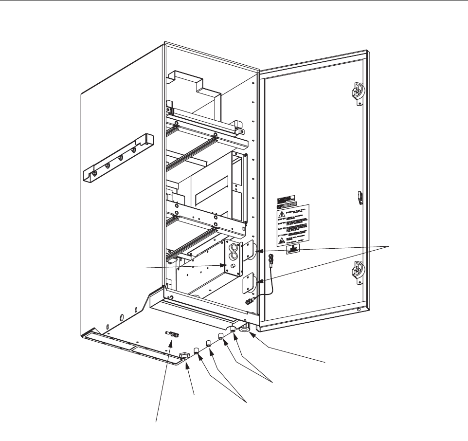
Figure 2-11. Slim-Style Single-STM Cabinet User Interface - Bottom Front View
6.2 Slim-Style Dual-STM Cabinet
The slim-style dual-STM cabinet, shown in Figure 2-12, is a NEMA-3R enclosure (with
removable dust filter) that houses the remote modules and protects them from the environment.
The cabinet consists of the enclosure, mounting slots for the STM and LPA modules, an AC
power interface, two lightning protectors, two fiber slack spools, and mounting slots for WDM
or CWDM (accessory) remote modules.
19296-B
(9) FIBER
SLACK SPOOLS
(13) GROUNDING
LUG
(14) 3/4-INCH NPT
THREADED HOLE
(10) FIBER CABLE
CONNECTOR
BOTTOM VIEW
OF CABINET
(15) CIRCUIT
BREAKER
RESET SWITCH
(11) PRIMARY LIGHTNING
PROTECTOR CONNECTOR
(12) DIVERSITY LIGHTNING
PROTECTOR CONNECTOR
(ACCESSORY)
ADCP-75-179 • Preliminary Issue A • September 2004 • Section 2: Description
Page 2-21
© 2004, ADC Telecommunications, Inc.
Figure 2-12. Slim-Style Dual-STM Cabinet
On an optional basis, the cabinet is available either with or without a battery compartment. The
battery compartment version provides a mounting tray for a back-up battery. The slim-style
cabinet is designed for use in an outdoor environment but may be mounted indoors if required.
Opening the hinged door provides full access to the interior of the enclosure to facilitate module
and cable installation.
The slim-style dual-STM cabinet user interface consists of the various connectors, fittings,
outlets, and switches that are provided on both the interior and exterior of the enclosure. The
user interface points are indicated in Figure 2-13 and Figure 2-14. For additional information,
refer to the Digivance Slim-Style Dual-STM Remote Unit W/Battery Installation and
Maintenance Manual (ADCP-75-172); or the Digivance Slim-Style Dual-STM Remote Unit
Without Battery Installation and Maintenance Manual (ADCP-75-174).
19573-A
20.7 IN.
(526 MM)
40.4 INCHES
(1026 MM)
WITH BATTERY
31 INCHES
(787 MM)
W/O BATTERY
18.8 IN
(478 MM)
ADCP-75-179 • Preliminary Issue A • September 2004 • Section 2: Description
Page 2-22
© 2004, ADC Telecommunications, Inc.
Figure 2-13. Slim-Style Dual-STM User Interface - Top Front View
(4) BATTERY
TRAYS
(7) DOOR
SWITCH
(8) AC
POWER CORDS
(1) AIR INLET
FILTER
(3) STM
MOUNTING
SLOTS
(2) LPA
MOUNTING
SLOTS
(5) WDM/CWDM
MOUNTING SLOTS
(6) CWDM
POWER CORD
19424-B
ADCP-75-179 • Preliminary Issue A • September 2004 • Section 2: Description
Page 2-23
© 2004, ADC Telecommunications, Inc.
Figure 2-14. Slim-Style Dual-STM User Interface - Bottom Front View
7 ACCESSORY ITEMS
This section provides a brief description of various accessory items that are available separately.
The accessory items may or may not be required depending on the application.
7.1 Remote Unit Back-up Battery Kit
A back-up battery kit (accessory item), shown in Figure 2-15, is available when the application
requires that the remote system remain operational during an AC power outage. A battery tray is
provided within specified enclosures for mounting the battery. The tray includes a heating pad
that keeps the battery warm during cold weather. A temperature sensor regulates the operation
19425-B
(9) FIBER
SLACK SPOOLS
(14) GROUNDING
LUG
(13) 3/4-INCH NPT
THREADED HOLE
(10) FIBER CABLE
CONNECTOR
BOTTOM VIEW
OF CABINET
(15) CIRCUIT
BREAKER
RESET SWITCH
(11) PRIMARY LIGHTNING
PROTECTOR CONNECTORS
(12) DIVERSITY LIGHTNING
PROTECTOR CONNECTORS
(OPTION)
ADCP-75-179 • Preliminary Issue A • September 2004 • Section 2: Description
Page 2-24
© 2004, ADC Telecommunications, Inc.
of the heating element and a circuit breaker provides overcurrent protection. The back-up
battery kit includes a wiring harness for connecting the battery to the STM. During normal
operation, the STM provides charging current to maintain the battery charge level. During an
AC power outage, the battery provides DC power to the STM to maintain system operation. The
battery can maintain operation of the RU for approximately 1 hour with the 50 Watt LPA and 2
hours with the 20 Watt LPA.
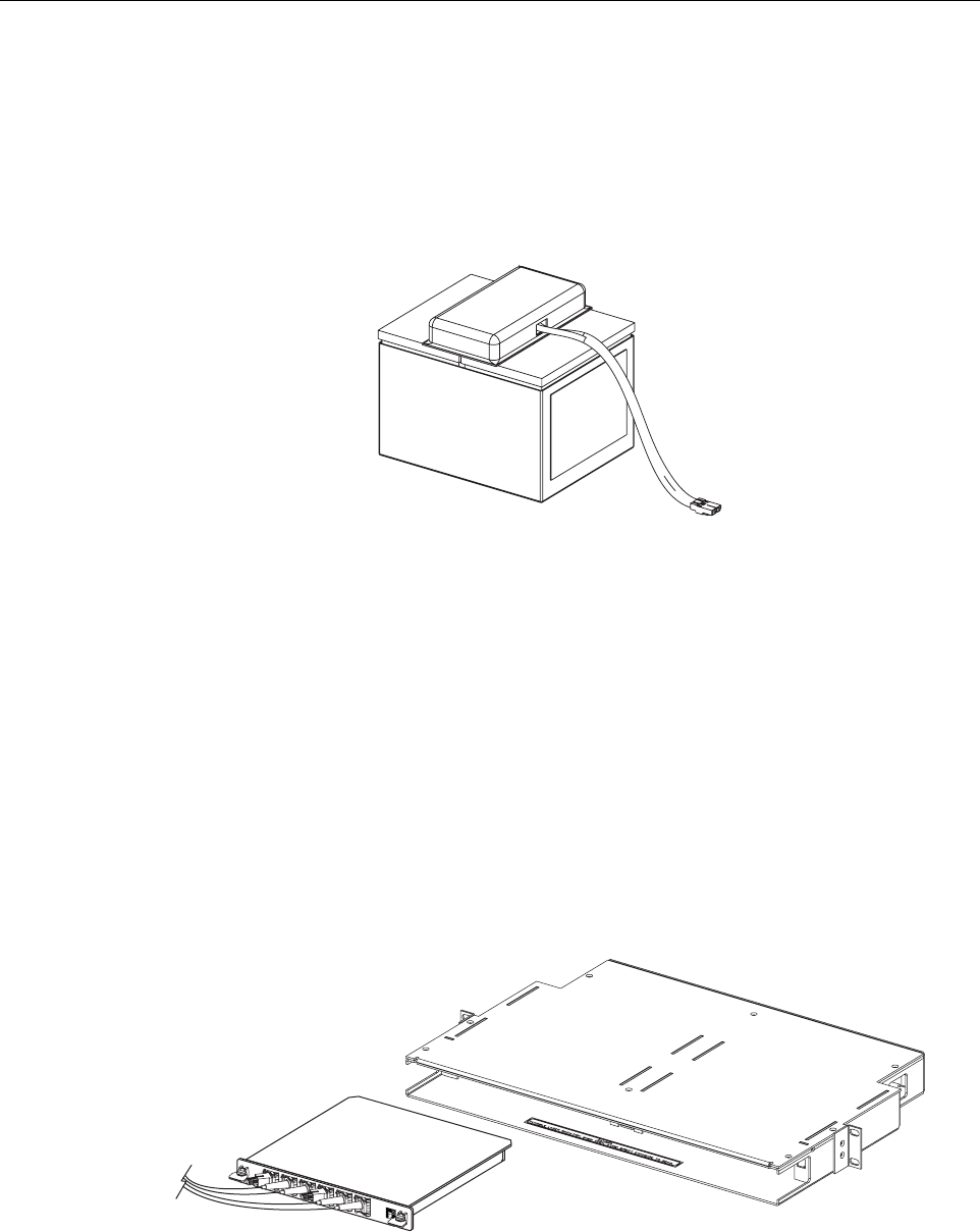
Figure 2-15. Back-Up Battery Kit
7.2 Wavelength Division Multiplexer System
The Wavelength Division Multiplexer (WDM) system is an accessory product that is used when
it is desirable or necessary to combine the forward and reverse path optical signals from one
Digivance system onto a single optical fiber. Each WDM system consists of a host module, host
module mounting shelf, and remote module. The WDM host module mounting shelf can
support two WDM host modules. The RU indoor mounting shelf and the outdoor cabinets
provide a mounting slot for installing a WDM remote module. The WDM host module and host
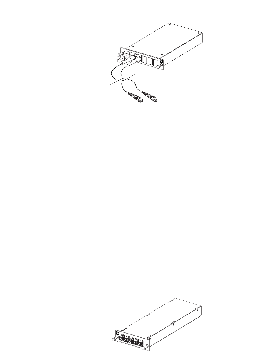
module mounting shelf are shown in Figure 2-16. The WDM remote module is shown in
Figure 2-17.
Figure 2-16. WDM Host Module and Host Module Mounting Shelf
17014-A
18646-A
ADCP-75-179 • Preliminary Issue A • September 2004 • Section 2: Description
Page 2-25
© 2004, ADC Telecommunications, Inc.
Figure 2-17. WDM Remote Module
Each WDM module consists of either one (remote module) or two (host module) bi-directional
wavelength division multiplexers mounted within a powder-paint coated sheet metal enclosure.
An SC-type optical connector port is provided for connecting the forward/reverse path optical
fiber to the WDM module. A pair of pigtail leads with SC-type connectors are provided for
connecting the WDM module to the forward and reverse path optical ports on the HU or STM.
7.3 Coarse Wavelength Division Multiplexer System
The Coarse Wavelength Division Multiplexer (CWDM) system is an accessory product that is
used when it is desirable or necessary to combine the forward and reserve path optical signals
from up to four Digivance systems onto a single optical fiber. Each CWDM system consists of a
Host Module, Host Module mounting shelf, and Remote Module. The CWDM Host Module
mounting shelf can support up to three CWDM Host Modules. The RU indoor mounting shelf
and the outdoor cabinets provide a mounting slot for installing a CWDM Remote Module.
The CWDM Remote Module is shown in Figure 2-18. The CWDM Host Module and Host
Module Mounting Shelf are shown in Figure 2-19. For complete information about the CWDM
system, refer to the Digivance System Coarse Wavelength Division Multiplexer User Manual
(ADCP-75-142).
Figure 2-18. CWDM Remote Module
17013-A
18648-A
ADCP-75-179 • Preliminary Issue A • September 2004 • Section 2: Description
Page 2-26
© 2004, ADC Telecommunications, Inc.
Figure 2-19. CWDM Host Module and Host Module Mounting Shelf
8 DIGIVANCE ELEMENT MANAGEMENT SYSTEM
The Digivance Element Management System (EMS) is a software-based network management
tool that provides control and monitoring functions for the Digivance system. Digivance EMS is
used to provision and configure new systems for operation, set system operating parameters, get
system alarm and status messages, and upgrade the system software. Digivance EMS supports
local control by an on-site service technician and also remote control through a Network
Operations Center (NOC) interface or an SNMP interface.
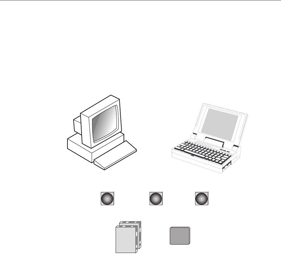
8.1 Digivance EMS Primary Components
The primary components of the Digivance EMS, shown in Figure 2-20, are packaged separately
from the various Digivance hardware items and consist of the following items: User Manuals,
mouse pad, license agreement, and three CD-ROMs which contain both software and various
technical publications. All software items install on a PC-type computer which is not provided.
A cable (DGVL-000000CBPC) for connecting the EMS computer to either the HU or RU is
available separately as an accessory item.
18647-A
ADCP-75-179 • Preliminary Issue A • September 2004 • Section 2: Description
Page 2-27
© 2004, ADC Telecommunications, Inc.
EMS CD-ROM: The EMS software, the Java 2 Version 1.3.1 Runtime Environment software,
and the Control and FPGA software (HU and RU firmware files) are loaded on the EMS CD-
ROM. The EMS software provides local monitor and control functions through a Graphical
User Interface (GUI) and remote monitor and control functions through the NOC/NEM
interface. Several Control and FPGA firmware programs are also included on the EMS CD-
ROM for downloading to the HU and RU in case either hardware unit is not already loaded with
the current firmware.
Figure 2-20. Digivance Element Management System
SNMP CD-ROM: The SNMP Proxy Agent software is optional and is provided on the SNMP
CD-ROM. The SNMP Proxy Agent software provides for remote monitor and control functions
through a network SNMP manager. If the SNMP interface is required for system operation, both
the EMS software and SNMP Proxy Agent software must be installed on the same computer.
The SNMP Proxy Agent software will not function without the EMS software.
Manuals CD-ROM: PDF files of the various Digivance technical publications are provided on
the Manuals CD-ROM. A copy of Acrobat Reader is required to open and print the publication
files. A copy of Acrobat Reader may be downloaded free of charge from the Adobe.com
website if necessary.
EMS CD-ROM SNMP CD-ROM MANUALS CD-ROM
OR
NOTE: COMPUTER NOT PROVIDED
18705-A
USER MANUALS
MOUSE PAD

ADCP-75-179 • Preliminary Issue A • September 2004 • Section 2: Description
Page 2-28
© 2004, ADC Telecommunications, Inc.
8.2 Software Installation
Software installation consists of inserting each software CD-ROM into the computer’s CD-
ROM drive and then running the software install programs. This places the EMS, Java 2
Runtime Environment, and SNMP Proxy Agent software files in assigned folders on the
computer’s hard drive. Software installation instructions are provided in the Digivance Element
Management System User Manual (ADCP-75-151).
8.3 Computer Operation
Permanent control and monitoring functions may be provided by a PC-type desk-top computer
that is permanently connected to a HU. The EMS program must be running in order for the
NOC interface to function. Both the EMS program and SNMP Proxy Agent program must be
running in order for the SNMP interface to function. A PC-type lap-top computer running just
the EMS program can be used as a portable network management tool for service and
maintenance purposes. The laptop computer may be connected temporarily to a HU or RU to
trouble-shoot problems on-site and then removed when the maintenance task is completed. The
specifications for the EMS computer are provided in the Digivance Element Management
System User Manual (ADCP-75-151).
8.4 Digivance EMS Computer Interface Connections
The service interface connection between the EMS computer and the HU or RU requires that
the EMS computer be equipped with a DB-9 connector that is configured to provide an RS-232
DCE interface. A straight-through RS-232 interface cable (accessory item) equipped with a
male DB-9 connector on one end and a PC-compatible connector on the other end is required to
link the EMS computer to the HU or RU. If multiple HUs are networked together using the
CAN interface, all units may be managed by connecting the EMS computer to the service
connector on any one of the networked HUs.
The NOC interface connection between the EMS computer and the NOC requires that the EMS
computer be equipped with a connector that is configured to provide an RS-232 ASCII
interface. The link between the EMS computer and the NOC would generally be supported by a
T1 system, DS0 with RS232 conversion, or other medium. Cables and equipment (not provided)
to support the RS-232 interface connection between the EMS computer and the NOC interface
are required.
The SNMP interface connection between the EMS computer and the SNMP manager requires
that the EMS computer be equipped with an Ethernet port. The link between the EMS computer
and a network SNMP manager would generally be supported by a Local Area Network (LAN).
Cables and equipment (not provided) to support the connection between the EMS computer and
the LAN are required.
ADCP-75-179 • Preliminary Issue A • September 2004 • Section 2: Description
Page 2-29
© 2004, ADC Telecommunications, Inc.
8.5 Digivance EMS User Interfaces
The Digivance EMS provides three user interfaces: the EMS Graphical User Interface (GUI),
the Network Operation Center–Network Element Manager (NOC/NEM) interface, and the
SNMP GUI interface. The EMS GUI, the NOC interface, and the SNMP GUI provide the same
basic functions. However, the NOC interface and the SNMP GUI cannot be used to download
new system software to the Digivance system. In addition, the SNMP GUI cannot be used to
assign a system site number to a HU/RU pair during installation.
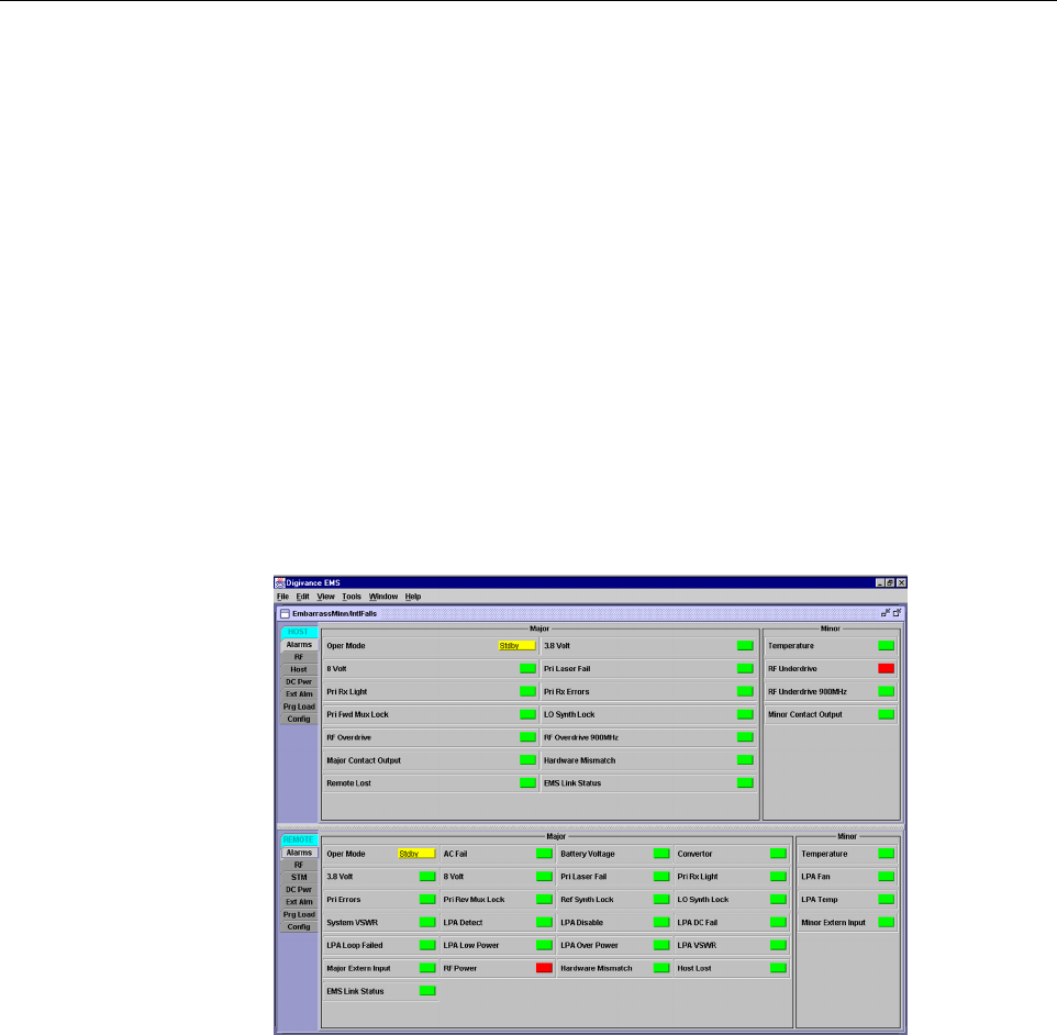
The EMS GUI is used for local control and monitoring operations. The EMS GUI consists of a
series of displays and screens, such as the one shown in Figure 2-21, that provide the user with
alarm and status information and that allow the user to set various operating parameters.
Directives are implemented by pointing and clicking on the desired action and also by entering
text in various dialog boxes. Refer to the Digivance Element Management System User Manual
(ADCP-75-151) for additional information.
Figure 2-21. Graphical User Interface Host/Remote Display
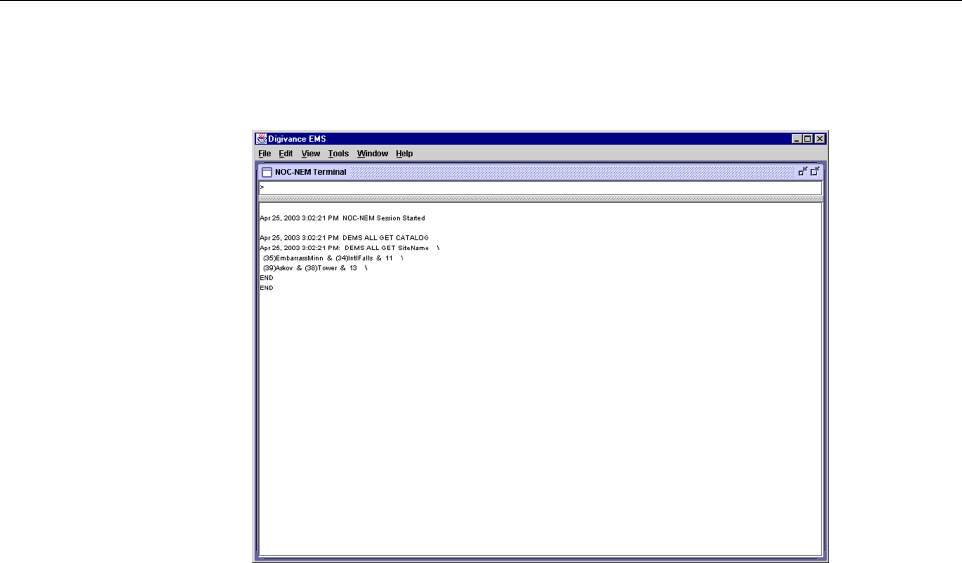
The NOC/NEM interface is a text-based command line interface that is used for remote control
and monitoring operations (except software download). The NOC/NEM interface consists of
defined ASCII text strings that are input as SET or GET commands followed by the action or
information required. A text string response is received from the specified Digivance system or
systems to confirm the requested action or to report the requested information. Examples of
several typical NOC-NEM interface commands and the responses received are shown in
Figure 2-22. The NOC/NEM interface requires only a VT100 terminal/emulator or a PC-type
computer that is loaded with a communication software such as Procomm Plus. While primarily
intended for use at the NOC, the NOC/NEM interface commands may also be input locally
from the EMS computer. Refer to the Digivance Element Management System User Manual
(ADCP-75-151) for additional information.
ADCP-75-179 • Preliminary Issue A • September 2004 • Section 2: Description
Page 2-30
© 2004, ADC Telecommunications, Inc.
Figure 2-22. NOC/NEM Interface Typical Commands
The SNMP interface is a GUI that is used for remote control and monitoring operations (except
software download and site number assignment). The SNMP interface uses a Management
Information Base (MIB) to define a list of identifiers that are supported by the SNMP agent.
The SNMP manager communicates with the SNMP agent over a LAN. Directives, based on the
MIB identifier, are issued by the SNMP manager to the SNMP agent along with instructions to
either get the specified identifier or set the specified identifier. The directive is then executed on
the Digivance system by the SNMP agent. The SNMP agent also has the ability to send
autonomous messages (called traps) to the SNMP manager to report changes in the status of the
managed system. The SNMP manager Stargazer Version 8.0 is available from ADC for use with
the LRCS SNMP agent. Other SNMP managers are available from various network
management software venders. Refer to the SNMP Agent Software User Manual (ADCP-75-
152) for additional information.

ADCP-75-179 • Preliminary Issue A • September 2004 • Section 2: Description
Page 2-31
© 2004, ADC Telecommunications, Inc.
9 SPECIFICATIONS
Refer to Table 2-4 for the Digivance SMR LRCS system nominal specifications. All
specifications apply after a five minute warm-up period.
Table 2-4. 800/900 MHz SMR System Nominal Specifications
PARAMETER SPECIFICATION REMARKS
Optical - Host and Remote Unit
Fiber type 9/125, single-mode
Number of fibers required
With WDM
Without WDM
1
2The wavelength division multi-
plexer (WDM) is an accessory
item.
Forward path wavelength 1550 nm
Reverse path wavelength 1310 nm
Optical transmit power output
Host Unit
Remote Unit 0 dBm
+2 dBm
Optical budget 25 dB For optical BER of 10–6
Optical Receive Input –15 dBm
Optical connectors Industry standard SC Host, remote, and WDM
Optical - Host and Remote WDM
Passband 1310 nm ± 20 nm
1550 nm ± 20 nm
Forward path insertion loss
Host WDM
Remote WDM
0.7 dB
0.3 dB Does not include connector loss
Reverse path insertion loss
Host WDM
Remote WDM
0.3 dB
0.7 dB Does not include connector loss
Isolation > 30 dB minimum
Return loss (Reflectance) < –50 dB All input ports
RF Forward Path - 800/900 MHz
System bandwidth 18 MHz
5 MHz 800 MHz transmit
900 MHz transmit
Frequency range 851–869 MHz
935–940 MHz
Gain of forward path
(Host input to Remote primary
antenna port)
85 dB with 35 Watt LPA At band center, room tempera-
ture, and 0 dB attenuation set-
ting. Includes power amplifier.
Gain flatness
Band flatness
Channel flatness ± 2.0 dB across freq. range
± 1 dB variation across any 1.25
MHz channel

ADCP-75-179 • Preliminary Issue A • September 2004 • Section 2: Description
Page 2-32
© 2004, ADC Telecommunications, Inc.
Gain variation ± 3 dB over temp and unit-to-
unit
Propagation delay 6 µs Excludes fiber delay
Configurable propagation delay
Range
Step size Up to 63 µs
0.1µs ± 100 ns
Plus standard propagation delay
Spurious
In-band self generated
Dynamic range (noise floor) –13 dBm at remote output
<–60 dBc
Transmit peak-to-average 10 dB
Two-tone Intermodulation <–60 dBc
Nominal composite RF input
signal level –43 dBm at 0 dB attenuation
–12 dBm at max. attenuation An input signal level of –43 dBm
provides maximum output power
Configurable input level
Range
Step size 31 dB
1 ± 0.5 dB ±10% of attenuation
monotonic
Composite RF Output power of
both bands with 35 Watt LPA 43.4 dBm (22 Watts) at remote
antenna port with –43 dBm input 35 Watts at LPA output
Configurable RF Output
Range
Step size 31 dB at remote unit
1 ±0.5 dB ±10% of attenuation
monotonic
Transmit path insertion loss 2.5 dB maximum
RF Reverse Path - 800/900 MHz
System bandwidth 18 MHz
5 MHz 800 MHz receive
900 MHz receive
Frequency range 806–824 MHz
896–901 MHz
Propagation delay 6 µs Excludes fiber delay
Configurable propagation delay
Range
Step size Up to 63 µs
0.1µs ±1 100 ns
Plus standard propagation delay
Gain of reverse path
Overall gain
Gain variation
30 ± 2 dB at band center at room
temperature
3 dB over temperature
Gain flatness
Band flatness
Channel flatness <1.5 dB across frequency range
<1 dB variation across any 1.25
MHz channel
Out-of-band rejection –40 dB at < 30 MHz
Table 2-4. 800/900 MHz SMR System Nominal Specifications, continued
PARAMETER SPECIFICATION REMARKS

ADCP-75-179 • Preliminary Issue A • September 2004 • Section 2: Description
Page 2-33
© 2004, ADC Telecommunications, Inc.
Spurious (in-band self gener-
ated) –110 dBm referred to input
Intermodulation –62 dBc
System noise figure 8 dB at mid-band
Configurable RF output
Range
Step size 31 dB
1 ± 0.5 dB ± 10% of attenuation
monotonic
Blocking dynamic range 70 dB
Level limiting ALC threshold –40 dBm ± 3 dB instantaneous
Level limiting ALC range 30 dB
Physical/Environmental/
Electrical - Host Unit
Dimensions (H×W×D) 3.5 × 17.1 × 12.2 inches
(88 × 433 × 311 mm) Dimension for width does not
include the mounting brackets
which can be installed for either
19- or 23-inch racks.
Mounting 19- or 23-inch rack EIA or WECO
Weight 18 lbs. (8.2 kg)
Weather resistance Indoor installation only
Operating temperature 0º to 50º C (32º to 122º F)
Storage temperature –40º to 70º C (–40º to 158ºF)
Humidity 10% to 90% No condensation
External alarm connector Screw-type terminals NO and NC relay contacts
DC power connector Screw-type terminal strip
RF coaxial cable connectors N-type (female)
Service connector DB-9 (female) RS-232 DTE interface
Auxiliary connector DB-9 (female) RS-232 DTE interface
CAN connectors RJ-45 jack
Power input ± 24 or ± 48 VDC ± 21 to ± 60 VDC
Power consumption 55 watts
Current rating 1 Amp at –48 VDC
Reliability at 25ºC MTBF 80,000 hours Excluding fans
Table 2-4. 800/900 MHz SMR System Nominal Specifications, continued
PARAMETER SPECIFICATION REMARKS

ADCP-75-179 • Preliminary Issue A • September 2004 • Section 2: Description
Page 2-34
© 2004, ADC Telecommunications, Inc.
Blank

ADCP-75-179 • Preliminary Issue A • September 2004 • Section 3: Operation
Page 3-1
© 2004, ADC Telecommunications, Inc.
SECTION 3: OPERATION
1 BEFORE STARTING OPERATION . . . . . . . . . . . . . . . . . . . . . . . . . . . . . . . . . . . . . . . . . . . . . . . . . . . . . . . . . . . .3-1
1.1 Tools and Materials . . . . . . . . . . . . . . . . . . . . . . . . . . . . . . . . . . . . . . . . . . . . . . . . . . . . . . . . . . . . . . .3-1
1.2 Readiness Check . . . . . . . . . . . . . . . . . . . . . . . . . . . . . . . . . . . . . . . . . . . . . . . . . . . . . . . . . . . . . . . . .3-2
2 TURN-UP SYSTEM AND VERIFY OPERATION . . . . . . . . . . . . . . . . . . . . . . . . . . . . . . . . . . . . . . . . . . . . . . . . . . . .3-2
2.1 Turn-Up Procedure. . . . . . . . . . . . . . . . . . . . . . . . . . . . . . . . . . . . . . . . . . . . . . . . . . . . . . . . . . . . . . . .3-3
2.2 Check/Download HU and RU Control Program and FPGA Program Software . . . . . . . . . . . . . . . . . . . . . . . . .3-6
2.3 Determine Forward Path Input Signal Level . . . . . . . . . . . . . . . . . . . . . . . . . . . . . . . . . . . . . . . . . . . . . .3-8
2.4 Enter Site Name and Site Number . . . . . . . . . . . . . . . . . . . . . . . . . . . . . . . . . . . . . . . . . . . . . . . . . . . . 3-10
2.5 Enter Host Forward Attenuation . . . . . . . . . . . . . . . . . . . . . . . . . . . . . . . . . . . . . . . . . . . . . . . . . . . . . . 3-11
2.6 Determine Output Signal Level at STM Antenna Port . . . . . . . . . . . . . . . . . . . . . . . . . . . . . . . . . . . . . . . 3-13
2.7 Enter Remote Forward Attenuation. . . . . . . . . . . . . . . . . . . . . . . . . . . . . . . . . . . . . . . . . . . . . . . . . . . . 3-13
2.8 Enter Host Reverse Attenuation . . . . . . . . . . . . . . . . . . . . . . . . . . . . . . . . . . . . . . . . . . . . . . . . . . . . . . 3-15
2.9 Enter Host Forward and Reverse Delay . . . . . . . . . . . . . . . . . . . . . . . . . . . . . . . . . . . . . . . . . . . . . . . . . 3-17
_________________________________________________________________________________________________________
1 BEFORE STARTING OPERATION
This section provides guidelines for turning-up the Digivance system, verifying that all units are
operating properly, testing to ensure that all performance requirements are satisfied, and
correcting any installation problems. This process assumes that the various units have been
installed in accordance with the system design plan.
1.1 Tools and Materials
The following tools and materials are required in order to complete the procedures in this
section:
• Portable spectrum analyzer or RF power meter
• AC/DC voltmeter
• External attenuators (if specified in system design plan)
• PC-type computer with Digivance Element Management System (EMS) Version 3.01
software installed
• Straight-through RS-232 DB-9 interface cable (accessory)
• Handset
• Pencil or pen
• Writing pad
Content Page

ADCP-75-179 • Preliminary Issue A • September 2004 • Section 3: Operation
Page 3-2
© 2004, ADC Telecommunications, Inc.
1.2 Readiness Check
Before starting the turn-up process, inspect the complete Digivance system to verify that all
components of the system are ready to be powered-up. This will ensure that no units of the
system will be damaged during turn-up and that all existing systems will continue to function
properly.
1.2.1 Host Unit Installation Checks
Complete the following checks at the HU prior to starting the turn-up process:
1. Verify that the ON/OFF switch on the HU is in the OFF position (press O).
2. At the fuse panel, install a 3 Amp GMT fuse in the circuit that supplies DC power to the HU.
3. Using a DC voltmeter, verify that the DC voltage level at the HU power terminals is
between ± 21 to ± 60 VDC (nominal ± 24 or ± 48 VDC). The DC power provided to the
HU can be either polarity.
4. Verify that all electrical and optical connections have been completed and that all optical
fibers, coaxial cables, and wires are properly routed and secured.
1.2.2 Remote Unit Installation Checks
Complete the following checks at the RU prior to starting the turn-up process:
1. Verify that the ON/OFF switch on the STM is in the OFF position (press O).
2. Verify that the RF ON/OF switch on the LPA in the OFF position.
3. At the AC breaker box, close the circuit breaker for the circuit that supplies AC power to
the RU.
4. Using an AC voltmeter, verify that the AC voltage level at the AC outlet is between 110
and 120 VAC (for 120 VAC powered systems) or between 220 and 240 VAC (for 240 VAC
powered systems).
5. Verify that all electrical and optical connections have been completed and that all optical
fibers, coaxial cables, and wires are properly routed and secured.
2 TURN-UP SYSTEM AND VERIFY OPERATION
The process of turning-up the system and verifying operation involves powering up the various
system components, verifying that the LED indicators show normal operation, setting the site
number and name, adjusting the RF signal levels, and adjusting the path delay.
Note: When connecting the equipment to the supply circuit, be sure to check equipment
nameplate ratings to avoid overloading circuits which may cause damage to over-current
protection devices and supply wiring.

ADCP-75-179 • Preliminary Issue A • September 2004 • Section 3: Operation
Page 3-3
© 2004, ADC Telecommunications, Inc.
2.1 Turn-Up Procedure
Each Digivance system must be turned-up separately before being networked together with
multiple systems through the CAN interface. Use the following procedure to turn-up each
Digivance system:
1. Temporarily disconnect the external alarm system or notify the alarm system provider that
testing is in progress.
2. If the HU is networked together with multiple HU’s, temporarily disconnect the CAN cables
from the NET IN and NET OUT ports of the HU.
3. Determine if the forward path composite input signal level at each host unit RF IN port
(851–869 FORWARD and 935–940 FORWARD) is appropriate to produce the required
RF output signal level. Adjust by installing an external attenuator if necessary. Refer to
Section 2.3 for the calculation and adjustment procedure.
4. Connect the EMS computer (if not already connected) to the SERVICE connector on the
HU or STM front panel. If necessary, a separate laptop computer loaded with EMS Version
3.01 software can be temporarily connected and used to initially configure the system.
5. At the HU: Place the ON/OFF switch on the HU in the ON position (press I).
6. At the RU: Make sure the RF switch on the LPA is in the OFF position. Then place the
ON/OFF switch on the STM in the ON position (press I).
7. Wait 6 to 8 seconds for the HU and the RU modules to initialize and then observe the LED
indicators on the HU, STM and LPA. Refer to Section 4 for the troubleshooting
procedures if the indicators do not respond as specified in Table 3-1.
Table 3-1. LED Indicator Operation at Initial Turn-Up
Note: By default, all HU’s and RU’s are programmed with the same site number and
name. This can cause problems for the EMS if multiple HU’s with the same site number
and site name are networked together through the CAN interface. It is therefore necessary
to temporarily disconnect the CAN interface cables from the HU when it is being
configured for operation until a unique site number and name can be assigned.
HOST UNIT SPECTRUM TRANSPORT MODULE 35 WATT LPA
POWER – Green AC POWER – Green FAIL – Off
STANDBY – Off STANDBY – Off SHUTDOWN – Red
HOST UNIT – Green HOST UNIT – Green Digital Display – FORCED
SHUTDOWN
REMOTE UNIT – Green STM – Green
DRIVE 851–869 and DRIVE
935–940 – Green, Yellow, or Red PA – Green
FWD/REV (PORT 1/PORT 2) –
Green VSWR – Green
FWD/REV (PORT 1/PORT 2) –
Green
ADCP-75-179 • Preliminary Issue A • September 2004 • Section 3: Operation
Page 3-4
© 2004, ADC Telecommunications, Inc.
8. Start up the EMS Version 3.01 software program. The EMS main window will open as
shown in Figure 3-1. Note: The EMS software should be installed on a PC-type computer
and the PC’s COMM port should be configured to interface with the HU. For information
about installing the EMS software and configuring the PC’s COMM port, refer to the
Digivance Element Management System Version 3.01 User Manual (ADCP-75-151).
Figure 3-1. Digivance Element Management System Main Window
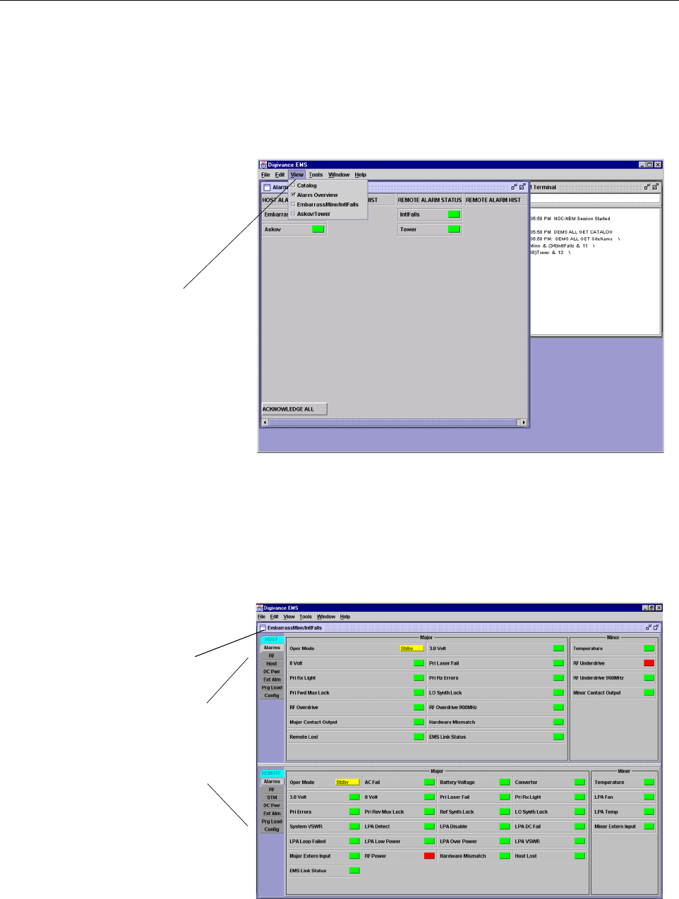
9. Open the View drop down menu and connect to the Host and Remote pair by selecting the
“NotNamed/NotNamed” Host/Remote pair. The HOST Alarms display and the REMOTE
Alarms display will open within the main window as shown in Figure 3-2.
Figure 3-2. Selecting Display Tabs
Click to view drop
down menu
Clicking on the tabs in
this list will open the cor-
responding display.
Host/Remote pair
site name

ADCP-75-179 • Preliminary Issue A • September 2004 • Section 3: Operation
Page 3-5
© 2004, ADC Telecommunications, Inc.
10. New Control program software and FPGA program software will be provided separately
on a “as needed” basis. If new Control and FPGA software is not provided with the
system, skip this step and proceed to step 11. If new Control and FPGA software is
provided, check the version numbers of the new software against the version numbers of
the software loaded on the Host and Remote Units. If the software loaded on the Host and
Remote Units is older than the new software, download the new software to both the Host
Unit and the Remote Unit. Refer to Section 2.2 for details.
11. Click on the HOST Config tab and on the REMOTE Config tab (see Figure 3-2). The
HOST Config display and the REMOTE Config display will open within the main window.
12. Enter the Site Name and Site Number for both the HOST and the REMOTE unit. Refer to
Section 2.4 for details.
13. If the Digivance system will be networked together with other Digivance systems,
reconnect the CAN cables to the HU’s NET IN and NET OUT ports.
14. Verify that no Major or Minor alarms (except Major or Minor Extern Alarm) are being
reported in either the HOST or REMOTE Alarm displays (except as indicated in the note
below) and that all alarm fields (except Major or Minor Extern Alarm) are green.
15. Click on the HOST RF tab (see Figure 3-2). The HOST RF display will open within the
main window.
16. Enter the Host Fwd Att (Forward Attenuation) value. This sets the forward input RF
signal level at the HU. Refer to Section 2.5 for details. By default, this value is set to 31
dB. If the DRIVE 851–869 and DRIVE 935–940 LED’s on the HU front panel were red,
both should turn green when this step is completed.
17. Determine if the RF output power at the STM ANTENNA is at the correct level per
channel up to a composite maximum of +43.4 dBm (22 Watts). Refer to Section 2.6 for
details.
18. Place the RF ON/OFF switch on the LPA in the ON position.
19. Verify that the SHUTDOWN LED indicator on the LPA turns from red to off and the
Digital Display message changes from FORCED SHUTDOWN to NORMAL
OPERATION.
20. Click on the REMOTE RF tab (see Figure 3-2). The REMOTE RF display will open
within the main window.
21. Enter the Remote Fwd Att value. This adjusts the RF output signal level at the STM
ANTENNA port. By default this value is set to 31 dB. Refer to Section 2.7 for details.
22. Click on the HOST RF tab (see Figure 3-2). The HOST RF display will open within the
main window.
Note: The Site Name and Site Number must be unique for each Digivance system.
Note: The Host RF Underdrive may indicate a minor alarm until the Host Fwd Att and
Remote Fwd Att values are set. The Remote LPA disable will indicate a major alarm until
the LPA is enabled.
ADCP-75-179 • Preliminary Issue A • September 2004 • Section 3: Operation
Page 3-6
© 2004, ADC Telecommunications, Inc.
23. Enter the Host Rev Att (Reverse Attenuation) values. This sets the reverse output RF
signal levels at the two host unit RF OUT ports (806–824 REVERSE and 896–901
REVERSE). By default each value is set to 31 dB. Refer to Section 2.8 for details.
24. If a delay adjustment is required, enter the Host Fwd Delay and Host Rev Delay values.
By default, the delay values are set to 0. Refer to Section 2.9 for details.
25. If a separate laptop computer loaded with the EMS software was used to initially
configure the system, disconnect the laptop computer from the SERVICE connector.
26. Reconnect the external alarm system or notify the alarm system provider that the turn-up
process has been completed.
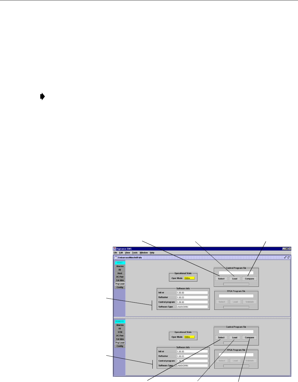
2.2 Check/Download HU and RU Control Program and FPGA Program Software
The HU’s and RU’s may require a Control program or FPGA program software download if
they are not loaded with the current software. Use the following procedure to check the Control
or FPGA program software and if necessary, to download the current software:
1. Click on the HOST Prg Load tab and on the REMOTE Prg Load tab. The HOST Prg
Load display and the REMOTE Prg Load display will open within the EMS main
window as shown in Figure 3-3.
Figure 3-3. HOST and REMOTE Prg Load Displays - Control Program Download
Note: When two or more HU’s are connected together through the CAN interface, only
one EMS computer is required to manage the networked Digivance systems. The EMS
computer may be connected to the SERVICE port on any one of the HUs in the network.
Click to open Select Control
Program window for HOST
Click to start down-
load to HOST.
Click to start down-
load to REMOTE.
Click to open Select Control
Program window for REMOTE.
Click to verify software version
before starting download.
Click to verify software version
before starting download.
Indicates control program
and FPGA software installed
on host unit
Indicates control program
and FPGA software installed
on remote unit
ADCP-75-179 • Preliminary Issue A • September 2004 • Section 3: Operation
Page 3-7
© 2004, ADC Telecommunications, Inc.
2. Within the HOST display, locate the Control Program File field.
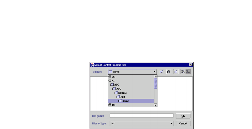
3. Click on the Select button (see Figure 3-3). The Select Control Program File window
will open as shown in Figure 3-4. Browse until the folder where the Control Program files
are located is selected and the software files are displayed in the window. Select the first
Control program file and then click on the OK button.
Figure 3-4. Select Control Program File Window
4. Click on the Compare button to determine if the software file selected is the same version
of the file already loaded on the unit. A message will appear to indicate the result.
5. If the software file is the same, a software download is not required. If the file selected is
different, check the version number shown in the Software Info field against the number
of the file displayed in the Control Program File field. If the file in the unit is older
(lower number) than the file selected, proceed with the software download. If the file in the
unit is the same as the file selected, the software download is not required.
6. To start the Control program download (if necessary), click on the Load button (see
Figure 3-3). When downloading is complete, verify that the program has loaded correctly.
7. Check the FPGA Program field. If the program shown is UNKNOWN, the unit has older
hardware and the FPGA program is non-replaceable. If a version number is shown, locate
the FPGA Program File field. Click on the Validate button to verify that the FPGA is
functional (working). A message will appear to indicate if the FPGA is functional or not.
8. If the FPGA is functional, click on the Select button. The Select FPGA Program File
window will open. Browse until the folder where the FPGA Program file is located and the
file is displayed in the window. Select the FPGA file and click on the OK button.
9. Check the version number shown in FPGA Program field against the version number of
the file displayed in the FPGA Program File field. If the software in the unit is older (has
a lower version number) than the file selected, proceed with the download. If the software
in the unit is the same as the file selected, the software download is not required.
10. To start the FPGA program download, click on the Load button. When downloading is
complete, verify that the program has loaded correctly.
11. Within the REMOTE display, locate the Control Program File field. Then repeat steps 3
through 10 to download the Control and FPGA program files to the REMOTE unit.

ADCP-75-179 • Preliminary Issue A • September 2004 • Section 3: Operation
Page 3-8
© 2004, ADC Telecommunications, Inc.
2.3 Determine Forward Path Input Signal Level
The level of the composite RF input signals received at the host unit 851–869 FORWARD RF
IN and 935–940 FORWARD RF IN ports will vary depending on the EBTS, the cable loss, the
number of channels present, and the required forward path composite power. If maximum
composite RF output is required at the RU, the level of the composite RF input signal received
at the HU must fall within a range of –12 to –43 dBm. If the signal level is not within this range,
it must be adjusted using an external attenuator.
When connecting a single HU to a single EBTS, use the following procedure to measure and
adjust the input RF signal level at the HU:
1. Connect a spectrum analyzer or power meter to the 851–869 MHz forward path output
port at the EBTS. The required signal levels and test points are shown in Figure 3-5.
2. If using a spectrum analyzer, proceed to step 3. If using a power meter, measure the
composite signal power from the EBTS and then proceed to step 5.
3. Measure the RF level of a single carrier, such as the control channel, in dBm. Make sure
the resolution bandwidth of the spectrum analyzer is 30 kHz. Maximum power in any
channel should not exceed 5W (+37 dB).
4. Calculate the total composite signal power from the EBTS using the following formula:
Ptot = Pc + 10Log N where,
Ptot is the total composite power in dBm
Pc is the power per carrier in dBm as measured in step 3, and
N is the total number of channels.
5. Determine the total cable loss that is imposed by the forward path coaxial cable that links
the EBTS to the HU and also any insertion loss imposed by splitters or combiners.
6. Subtract the total cable loss and any insertion losses from the total composite power
calculated in step 4.
7. Subtract –25 (midpoint of the required range) from the value determined in step 6. The
difference (which should be positive) equals the value of the external attenuator that is
required to reduce the forward path signal level to fall within the required range. The
following formula outlines the required calculations for steps 6 and 7:
Ptot – (Cable and insertion loss) – (–25) = Value of external attenuator required
8. Select an attenuator that is as close to the value calculated in step 7 as possible. Select a
value that will adjust the signal level of the composite input signal to fall within the
specified range.
Note: Check the input rating of the test equipment and the output rating of the EBTS. To
avoid burning out the spectrum analyzer or power meter, it may be necessary to insert a
30 dB 100W (or similar) attenuator between the EBTS and test equipment.
Note: If the input signal level is already within the required range of –12 to –43 dBm, then
no external attenuator is required.
ADCP-75-179 • Preliminary Issue A • September 2004 • Section 3: Operation
Page 3-9
© 2004, ADC Telecommunications, Inc.
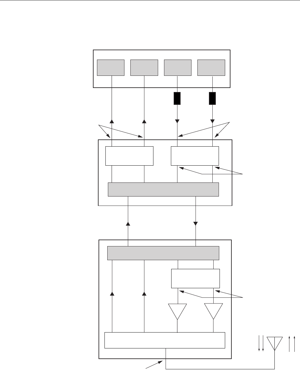
Figure 3-5. Signal Levels, Test Points, and Adjustments
FORWARD PATH
INPUT SIGNAL LEVEL
AT HOST UNIT
(-25 dBm TYPICAL
COMPOSITE FOR
FULL POWER)
HOST UNIT
REMOTE UNIT
ENHANCED BASE TRANSCEIVER STATION
20012-A
OPTICAL LINK
ANTENNA
QUADRAPLEXER/FILTER
FORWARD PATH SIGNAL
LEVEL AS SET BY HOST
FORWARD PATH
ATTENUATORS
(ADJUST TO -43 dBm
COMPOSITE
FOR FULL POWER)
REVERSE PATH OUTPUT
SIGNAL LEVEL AS SET BY HOST
REVERSE PATH ATTENUATORS
MAXIMUM OUTPUT SIGNAL
LEVEL AT ANTENNA PORT
(43.4 dBm AT FULL POWER)
FORWARD PATH SIGNAL
LEVEL AS SET BY REMOTE
FORWARD PATH
ATTENUATORS
LPA LPA
EXTERNAL
ATTENUATORS
851-869
TRANS-
MITTER
935-940
TRANS-
MITTER
0 to 31 dB
ATTENUATORS
(HOST FWD ATT)
0 to 31 dB
ATTENUATORS
(HOST REV ATT)
0 to 31 dB
ATTENUATORS
(REMOTE FWD ATT)
RF, OPTICS,
AND CONTROL
RF, OPTICS,
AND CONTROL
896-901
RECEIVER
806-824
RECEIVER
ADCP-75-179 • Preliminary Issue A • September 2004 • Section 3: Operation
Page 3-10
© 2004, ADC Telecommunications, Inc.
9. Install the external attenuator in the coaxial cable that is connected to the 851–869
FORWARD RF IN port at the HU.
10. Repeat steps 1–8 for the 935–940 forward path output port at the EBTS. Install the
external attenuator in the coaxial cable that is connected to the 935–940 FORWARD RF
IN port at the HU.
11. Subtract the value of the external attenuators from the total composite signal power (Ptot)
and record the result. This value will be required when setting the attenuation of the HU’s
internal forward path attenuators.
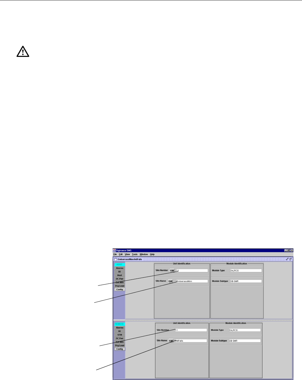
2.4 Enter Site Name and Site Number
All HU’s and RU’s are programmed with the same site name and site number. It is therefore
necessary to assign a unique site name and site number to the HU and RU before they can be
connected to the same CAN network. Use the following procedure to assign a unique site name
and number to each HU and RU system:
1. Click on the HOST Config tab and on the REMOTE Config tab. The HOST Config
display and the REMOTE Config display will open within the EMS main window as
shown in Figure 3-6.
Figure 3-6. HOST and REMOTE Config Displays
Caution: The Host Unit can be damaged if it is overdriven by the EBTS. Always install an
external protective attenuator at the Host Unit FWD RF IN port if the forward path composite
input signal level is greater than –12 dBm.
HOST Site Number
HOST Site Name
REMOTE Site Number
(Entered automatically
when the HOST site
number is selected)
REMOTE Site Name
Click on the Edit button
to open pop-up screen