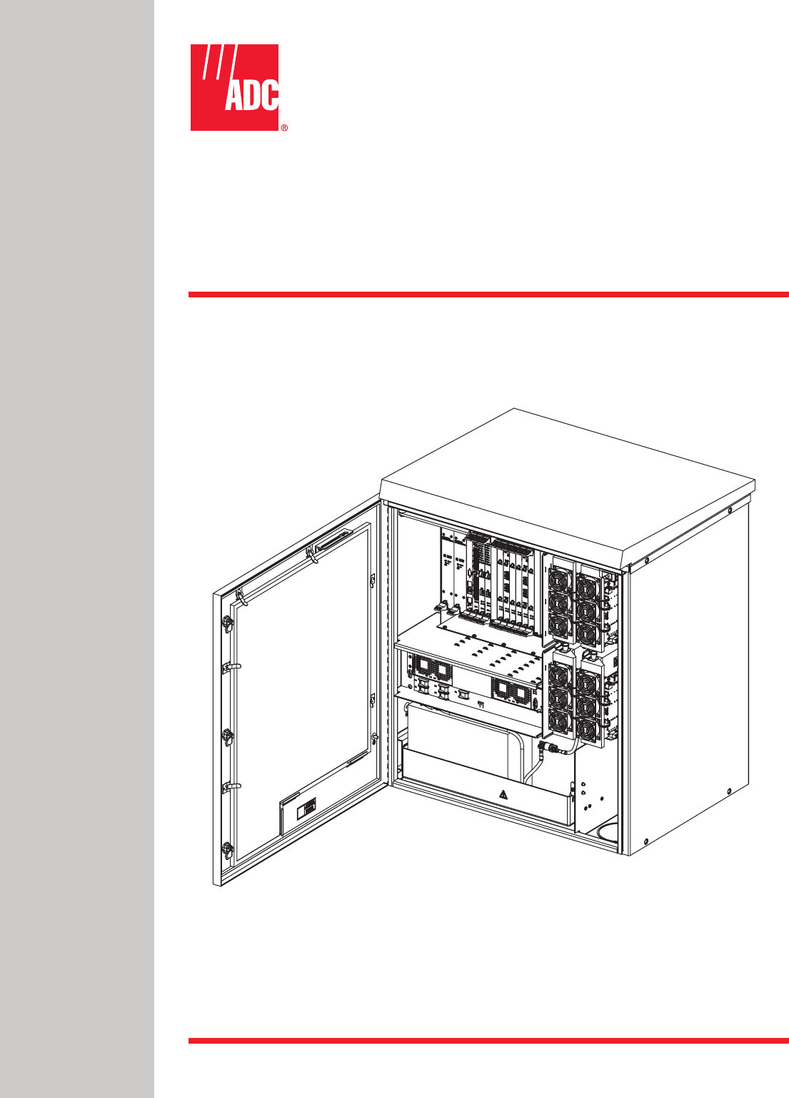
ADC Telecommunications DNXSMR1A Digivance® NXD SMR 900 MHz System User Manual 75210
ADC Telecommunications Inc Digivance® NXD SMR 900 MHz System 75210
Contents
- 1. User Manual 1
- 2. User Manual 2
- 3. User Manual 3
- 4. User Manual 4
User Manual 1
ADCP-75-210
Issue 1
November 2006
1356011 Rev A
Digivance® NXD
Radio Access Node (RAN)
Installation and Maintenance Manual
21227-A

ADCP-75-210 • Issue 1 • November 2006 • Preface
Page ii
COPYRIGHT
© 2006, ADC Telecommunications, Inc.
All Rights Reserved
Printed in the U.S.A.
REVISION HISTORY
TRADEMARK INFORMATION
Digivance is a registered trademark of ADC Telecommunications, Inc.
ADC is a trademark of ADC Telecommunications, Inc.
DISCLAIMER OF LIABILITY
Contents herein are current as of the date of publication. ADC reserves the right to change the contents without prior notice. In no
event shall ADC be liable for any damages resulting from loss of data, loss of use, or loss of profits and ADC further
disclaims any and all liability for indirect, incidental, special, consequential or other similar damages. This disclaimer of
liability applies to all products, publications and services during and after the warranty period.
This publication may be verified at any time by contacting ADC’s Technical Assistance Center at 1-800-366-3891, extension 73475
(in U.S.A. or Canada) or 952-917-3475 (outside U.S.A. and Canada), or by e-mail to connectivity_tac@adc.com.
ISSUE DATE REASON FOR CHANGE
1 11/2006 Original.
ADC Telecommunications, Inc.
P.O. Box 1101, Minneapolis, Minnesota 55440-1101
In U.S.A. and Canada: 1-800-366-3891
Outside U.S.A. and Canada: (952) 938-8080
Fax: (952) 917-1717

ADCP-75-210 • Issue 1 • November 2006 • Preface
Page iii
© 2006, ADC Telecommunications, Inc.
TABLE OF CONTENTS
Content Page
About This Manual . . . . . . . . . . . . . . . . . . . . . . . . . . . . . . . . . . . . . . . . . . . . . . . . . . . . . . . . . . . . . . . . . . . . . . . . . . vii
RELATED PUBLICATIONS . . . . . . . . . . . . . . . . . . . . . . . . . . . . . . . . . . . . . . . . . . . . . . . . . . . . . . . . . . . . . . . . . . . . . . vii
AdmonishmentS . . . . . . . . . . . . . . . . . . . . . . . . . . . . . . . . . . . . . . . . . . . . . . . . . . . . . . . . . . . . . . . . . . . . . . . . . . . .viii
General Safety Precautions . . . . . . . . . . . . . . . . . . . . . . . . . . . . . . . . . . . . . . . . . . . . . . . . . . . . . . . . . . . . . . . . . . . .viii
Safe Working Distances . . . . . . . . . . . . . . . . . . . . . . . . . . . . . . . . . . . . . . . . . . . . . . . . . . . . . . . . . . . . . . . . . . . . . . . .ix
STANDARDS CERTIFICATION . . . . . . . . . . . . . . . . . . . . . . . . . . . . . . . . . . . . . . . . . . . . . . . . . . . . . . . . . . . . . . . . . . . .ix
LIST OF ACRONYMS AND ABBREVIATIONS . . . . . . . . . . . . . . . . . . . . . . . . . . . . . . . . . . . . . . . . . . . . . . . . . . . . . . . . . . . x
1 PRODUCT DESCRIPTION . . . . . . . . . . . . . . . . . . . . . . . . . . . . . . . . . . . . . . . . . . . . . . . . . . . . . . . . . . . . . . . . . . 1
1.1 General Description . . . . . . . . . . . . . . . . . . . . . . . . . . . . . . . . . . . . . . . . . . . . . . . . . . . . . . . . . . . . . . . . 1
1.2 System Function . . . . . . . . . . . . . . . . . . . . . . . . . . . . . . . . . . . . . . . . . . . . . . . . . . . . . . . . . . . . . . . . . . 2
1.3 High-Level View . . . . . . . . . . . . . . . . . . . . . . . . . . . . . . . . . . . . . . . . . . . . . . . . . . . . . . . . . . . . . . . . . . 3
1.4 User Interface . . . . . . . . . . . . . . . . . . . . . . . . . . . . . . . . . . . . . . . . . . . . . . . . . . . . . . . . . . . . . . . . . . . . 4
1.5 Dimensions and Specifications . . . . . . . . . . . . . . . . . . . . . . . . . . . . . . . . . . . . . . . . . . . . . . . . . . . . . . . . 6
1.6 RAN Cabinet . . . . . . . . . . . . . . . . . . . . . . . . . . . . . . . . . . . . . . . . . . . . . . . . . . . . . . . . . . . . . . . . . . . . . 8
1.6.1 Mounting . . . . . . . . . . . . . . . . . . . . . . . . . . . . . . . . . . . . . . . . . . . . . . . . . . . . . . . . . . . . . . . . 8
1.6.2 Fiber Optic Cable Entry. . . . . . . . . . . . . . . . . . . . . . . . . . . . . . . . . . . . . . . . . . . . . . . . . . . . . . . 9
1.6.3 Antenna Cable Connections . . . . . . . . . . . . . . . . . . . . . . . . . . . . . . . . . . . . . . . . . . . . . . . . . . . 9
1.6.4 AC Power Wiring Entry and Grounding . . . . . . . . . . . . . . . . . . . . . . . . . . . . . . . . . . . . . . . . . . . . 9
1.6.5 Ventilation . . . . . . . . . . . . . . . . . . . . . . . . . . . . . . . . . . . . . . . . . . . . . . . . . . . . . . . . . . . . . . . 9
1.7 RAN Chassis and Electronic Modules . . . . . . . . . . . . . . . . . . . . . . . . . . . . . . . . . . . . . . . . . . . . . . . . . . . 10
1.7.1 cPCI Power Supply Modules . . . . . . . . . . . . . . . . . . . . . . . . . . . . . . . . . . . . . . . . . . . . . . . . . . 12
1.7.2 Central Processing Unit (CPU) Module . . . . . . . . . . . . . . . . . . . . . . . . . . . . . . . . . . . . . . . . . . . 13
1.7.3 System Interface (STF2) Module . . . . . . . . . . . . . . . . . . . . . . . . . . . . . . . . . . . . . . . . . . . . . . . 14
1.7.4 Synchronous Interface (SIF) Module . . . . . . . . . . . . . . . . . . . . . . . . . . . . . . . . . . . . . . . . . . . . 15
1.7.5 Small Form-Factor Pluggable (SFP) Optical Transceiver. . . . . . . . . . . . . . . . . . . . . . . . . . . . . . . 17
1.7.6 RAN Down Converter (RDC or RDC2) Module. . . . . . . . . . . . . . . . . . . . . . . . . . . . . . . . . . . . . . . 17
1.7.7 RAN Up Converter (RUC2.X or RUC3) Module . . . . . . . . . . . . . . . . . . . . . . . . . . . . . . . . . . . . . . 19
1.7.8 Fan Access Panel . . . . . . . . . . . . . . . . . . . . . . . . . . . . . . . . . . . . . . . . . . . . . . . . . . . . . . . . . 20
1.7.9 800 MHz Multicoupler (C/MCPLR) . . . . . . . . . . . . . . . . . . . . . . . . . . . . . . . . . . . . . . . . . . . . . . 20
1.7.10 1900 MHz Multicoupler (P/MCPLR) . . . . . . . . . . . . . . . . . . . . . . . . . . . . . . . . . . . . . . . . . . . . . 22
1.8 Rectifier Shelf. . . . . . . . . . . . . . . . . . . . . . . . . . . . . . . . . . . . . . . . . . . . . . . . . . . . . . . . . . . . . . . . . . . 23
1.8.1 Rectifier Module . . . . . . . . . . . . . . . . . . . . . . . . . . . . . . . . . . . . . . . . . . . . . . . . . . . . . . . . . . 23
1.8.2 Low Voltage Disconnect (LVD) Unit . . . . . . . . . . . . . . . . . . . . . . . . . . . . . . . . . . . . . . . . . . . . . 24
1.9 Power Amplifier Assembly . . . . . . . . . . . . . . . . . . . . . . . . . . . . . . . . . . . . . . . . . . . . . . . . . . . . . . . . . . 25
1.10 Multiplexer System . . . . . . . . . . . . . . . . . . . . . . . . . . . . . . . . . . . . . . . . . . . . . . . . . . . . . . . . . . . . . . . 26
1.11 Circuit Breaker Panel . . . . . . . . . . . . . . . . . . . . . . . . . . . . . . . . . . . . . . . . . . . . . . . . . . . . . . . . . . . . . . 28
1.12 Backup Batteries . . . . . . . . . . . . . . . . . . . . . . . . . . . . . . . . . . . . . . . . . . . . . . . . . . . . . . . . . . . . . . . . . 28
1.13 Antenna . . . . . . . . . . . . . . . . . . . . . . . . . . . . . . . . . . . . . . . . . . . . . . . . . . . . . . . . . . . . . . . . . . . . . . . 29
2 STANDARD INSTALLATION PROCEDURES . . . . . . . . . . . . . . . . . . . . . . . . . . . . . . . . . . . . . . . . . . . . . . . . . . . . . 29
2.1 Installation Overview . . . . . . . . . . . . . . . . . . . . . . . . . . . . . . . . . . . . . . . . . . . . . . . . . . . . . . . . . . . . . . 30
2.2 Unpacking and Inspection. . . . . . . . . . . . . . . . . . . . . . . . . . . . . . . . . . . . . . . . . . . . . . . . . . . . . . . . . . . 31

ADCP-75-210 • Issue 1 • November 2006 • Preface
Page iv
© 2006, ADC Telecommunications, Inc.
TABLE OF CONTENTS
Content Page
2.3 Required Materials and Tools . . . . . . . . . . . . . . . . . . . . . . . . . . . . . . . . . . . . . . . . . . . . . . . . . . . . . . . . 31
2.4 Site Preparation . . . . . . . . . . . . . . . . . . . . . . . . . . . . . . . . . . . . . . . . . . . . . . . . . . . . . . . . . . . . . . . . . 32
2.4.1 Space Requirements . . . . . . . . . . . . . . . . . . . . . . . . . . . . . . . . . . . . . . . . . . . . . . . . . . . . . . . 32
2.4.2 Power Requirements . . . . . . . . . . . . . . . . . . . . . . . . . . . . . . . . . . . . . . . . . . . . . . . . . . . . . . . 32
2.4.3 Antenna Requirement . . . . . . . . . . . . . . . . . . . . . . . . . . . . . . . . . . . . . . . . . . . . . . . . . . . . . . 33
2.4.4 RF Cable Requirements . . . . . . . . . . . . . . . . . . . . . . . . . . . . . . . . . . . . . . . . . . . . . . . . . . . . . 33
2.4.5 Fiber Requirements . . . . . . . . . . . . . . . . . . . . . . . . . . . . . . . . . . . . . . . . . . . . . . . . . . . . . . . . 33
2.5 Installing a RAN Cabinet on a Wooden Utility Pole . . . . . . . . . . . . . . . . . . . . . . . . . . . . . . . . . . . . . . . . . . 34
2.5.1 Site Requirements Unique to Pole Mounting Locations. . . . . . . . . . . . . . . . . . . . . . . . . . . . . . . . 34
2.5.2 Pole Loading Analysis . . . . . . . . . . . . . . . . . . . . . . . . . . . . . . . . . . . . . . . . . . . . . . . . . . . . . . 35
2.5.3 Installing the Cabinet Mounting Bracket . . . . . . . . . . . . . . . . . . . . . . . . . . . . . . . . . . . . . . . . . . 36
2.5.4 Mounting the RAN Cabinet on the Bracket. . . . . . . . . . . . . . . . . . . . . . . . . . . . . . . . . . . . . . . . . 38
2.5.5 Installing the Rain Shields . . . . . . . . . . . . . . . . . . . . . . . . . . . . . . . . . . . . . . . . . . . . . . . . . . . 38
2.6 Installing a RAN Cabinet on a Concrete Pad . . . . . . . . . . . . . . . . . . . . . . . . . . . . . . . . . . . . . . . . . . . . . . 39
2.6.1 Pouring a Concrete Pad . . . . . . . . . . . . . . . . . . . . . . . . . . . . . . . . . . . . . . . . . . . . . . . . . . . . . 40
2.6.2 Mounting the Cabinet on a Concrete Pad . . . . . . . . . . . . . . . . . . . . . . . . . . . . . . . . . . . . . . . . . 40
2.6.3 Installing the Pedestal Enclosure. . . . . . . . . . . . . . . . . . . . . . . . . . . . . . . . . . . . . . . . . . . . . . . 42
2.7 Other Standard Installation Procedures . . . . . . . . . . . . . . . . . . . . . . . . . . . . . . . . . . . . . . . . . . . . . . . . . 43
2.7.1 Installing a Solar Shield. . . . . . . . . . . . . . . . . . . . . . . . . . . . . . . . . . . . . . . . . . . . . . . . . . . . . 43
2.7.2 Installing a Ground Wire . . . . . . . . . . . . . . . . . . . . . . . . . . . . . . . . . . . . . . . . . . . . . . . . . . . . 44
2.7.3 Installing RF Cabling . . . . . . . . . . . . . . . . . . . . . . . . . . . . . . . . . . . . . . . . . . . . . . . . . . . . . . . 45
2.7.3.1 Weatherproofing RF Cables . . . . . . . . . . . . . . . . . . . . . . . . . . . . . . . . . . . . . . . . . . . . . . . . 46
2.7.3.2 Routing and Securing RF Cables . . . . . . . . . . . . . . . . . . . . . . . . . . . . . . . . . . . . . . . . . . . . 46
2.7.4 Installing Pre-Connectorized Indoor/Outdoor Fiber Optic Cable . . . . . . . . . . . . . . . . . . . . . . . . . . 47
2.7.5 Installing AC Power . . . . . . . . . . . . . . . . . . . . . . . . . . . . . . . . . . . . . . . . . . . . . . . . . . . . . . . . 49
2.7.6 Installing Backup Batteries (Extended or Glitch) . . . . . . . . . . . . . . . . . . . . . . . . . . . . . . . . . . . . 50
2.7.6.1 Battery Safety Rules . . . . . . . . . . . . . . . . . . . . . . . . . . . . . . . . . . . . . . . . . . . . . . . . . . . . . 50
2.7.6.2 Battery Installation . . . . . . . . . . . . . . . . . . . . . . . . . . . . . . . . . . . . . . . . . . . . . . . . . . . . . . 51
3 INSTALLING AN EXTENSION RAN (POLE MOUNT) . . . . . . . . . . . . . . . . . . . . . . . . . . . . . . . . . . . . . . . . . . . . . . . . 54
4 NON-STANDARD INSTALLATION PROCEDURES . . . . . . . . . . . . . . . . . . . . . . . . . . . . . . . . . . . . . . . . . . . . . . . . . . 57
4.1 Installing an Electronic Module . . . . . . . . . . . . . . . . . . . . . . . . . . . . . . . . . . . . . . . . . . . . . . . . . . . . . . . 57
4.1.1 Installing a Central Processing Unit (CPU) Module. . . . . . . . . . . . . . . . . . . . . . . . . . . . . . . . . . . 60
4.1.2 Installing a Systems Interface (STF2) Module . . . . . . . . . . . . . . . . . . . . . . . . . . . . . . . . . . . . . . 61
4.1.3 Installing a Synchronous Interface (SIF) Module . . . . . . . . . . . . . . . . . . . . . . . . . . . . . . . . . . . . 62
4.1.4 Installing a Small Form-Factor Optical Transceiver (SFP) . . . . . . . . . . . . . . . . . . . . . . . . . . . . . . 63
4.1.5 Installing a RAN Down Converter (RDC or RDC2) Module . . . . . . . . . . . . . . . . . . . . . . . . . . . . . . 63
4.1.6 Installing a RAN Up Converter (RUC2.X or RUC3) Module . . . . . . . . . . . . . . . . . . . . . . . . . . . . . . 64
4.2 Installing cPCI Chassis Air Baffles . . . . . . . . . . . . . . . . . . . . . . . . . . . . . . . . . . . . . . . . . . . . . . . . . . . . . 66
4.3 Installing a Rectifier Module. . . . . . . . . . . . . . . . . . . . . . . . . . . . . . . . . . . . . . . . . . . . . . . . . . . . . . . . . 66
4.4 Installing a Compact PCI Power Supply (cPCI P/S) Module . . . . . . . . . . . . . . . . . . . . . . . . . . . . . . . . . . . . 68
4.5 Installing a Power Amplifier Assembly . . . . . . . . . . . . . . . . . . . . . . . . . . . . . . . . . . . . . . . . . . . . . . . . . . 68

ADCP-75-210 • Issue 1 • November 2006 • Preface
Page v
© 2006, ADC Telecommunications, Inc.
TABLE OF CONTENTS
Content Page
5 MAINTENANCE PROCEDURES . . . . . . . . . . . . . . . . . . . . . . . . . . . . . . . . . . . . . . . . . . . . . . . . . . . . . . . . . . . . . . 70
5.1 cPCI Fan Replacement Procedure . . . . . . . . . . . . . . . . . . . . . . . . . . . . . . . . . . . . . . . . . . . . . . . . . . . . . 70
5.2 Cleaning or Replacing an Air Inlet Filter . . . . . . . . . . . . . . . . . . . . . . . . . . . . . . . . . . . . . . . . . . . . . . . . . 70
6 CUSTOMER INFORMATION AND ASSISTANCE . . . . . . . . . . . . . . . . . . . . . . . . . . . . . . . . . . . . . . . . . . . . . . . . . . . 72

ADCP-75-210 • Issue 1 • November 2006 • Preface
Page vi
© 2006, ADC Telecommunications, Inc.
TABLE OF CONTENTS
Content Page

ADCP-75-210 • Issue 1 • November 2006 • Preface
Page vii
© 2006, ADC Telecommunications, Inc.
ABOUT THIS MANUAL
This manual provides the following information:
• An overview of the Digivance NXD system;
• A description of the NXD system Radio Access Node (RAN);
• Installation procedures for the RAN;
• Maintenance procedures for the RAN;
• Product support information.
Procedures for installing and operating other NXD system components including the system
“Hub” and the EMS software that provides a user interface for the system, are available in other
ADC publications, listed under “Related Publications” below, and at appropriate points within
this manual.
RELATED PUBLICATIONS
Listed below are related manuals, their content, and their publication numbers. Copies of these
publications can be ordered by contacting the Technical Assistance Center at 1-800-366-3891,
extension 73476 (in U.S.A. or Canada) or 952-917-3476 (outside U.S.A. and Canada). All ADC
technical publications are available for downloading from the ADC web site at www.adc.com.
Digivance CXD/NXD Hub Installation and Maintenance Manual 75-193
Provides instructions for installing and operating the NXD system Hub.
Digivance CXD/NXD SNMP Agent and Fault Isolation User Guide 75-195
Describes how to troubleshoot the system using the parameters accessed
through the NXD system SNMP agents.
Digivance CXD/NXD Element Management System User Manual 75-199
Provides instructions for installing and using the Element Management System
(EMS) software for the NXD system.
Digivance NXD Multi-Band Distributed Antenna System Operation Manual 75-209
Provides instructions for turning up and operating NXD equipment.
2 in. O.D. Quad Cellular/PCS Omni-Directional Antenna Installation Manual 75-215
Provides instructions for installing an RF antenna for the NXD system
9 in. O.D. Quad Cellular/PCS Omni-Directional Antenna Installation Manual 75-221
Provides instructions for installing an RF antenna for the NXD system
Title/Description ADCP Number
ADCP-75-210 • Issue 1 • November 2006 • Preface
Page viii
© 2006, ADC Telecommunications, Inc.
ADMONISHMENTS
Important safety admonishments are used throughout this manual to warn of possible hazards to
persons or equipment. An admonishment identifies a possible hazard and then explains what
may happen if the hazard is not avoided. The admonishments — in the form of Dangers,
Warnings, and Cautions — must be followed at all times.
These warnings are flagged by use of the triangular alert icon (seen below), and are listed in
descending order of severity of injury or damage and likelihood of occurrence.
GENERAL SAFETY PRECAUTIONS
-
Danger: Danger is used to indicate the presence of a hazard that will cause severe personal
injury, death, or substantial property damage if the hazard is not avoided.
Warning: Warning is used to indicate the presence of a hazard that can cause severe personal
injury, death, or substantial property damage if the hazard is not avoided.
Caution: Caution is used to indicate the presence of a hazard that will or can cause minor
personal injury or property damage if the hazard is not avoided.
Warning: Wet conditions increase the potential for receiving an electrical shock when
installing or using electrically-powered equipment. To prevent electrical shock, never install or
use electrical equipment in a wet location or during a lightning storm.
Danger: This equipment uses a Class 1 Laser according to FDA/CDRH rules. Laser radiation
can seriously damage the retina of the eye. Do not look into the ends of any optical fiber. Do not
look directly into the optical transceiver of any digital unit or exposure to laser radiation may
result. An optical power meter should be used to verify active fibers. A protective cap or hood
MUST be immediately placed over any radiating transceiver or optical fiber connector to avoid
the potential of dangerous amounts of radiation exposure. This practice also prevents dirt
particles from entering the adapter or connector.
Caution: This system is a RF Transmitter and continuously emits RF energy. Maintain 3 foot
(91.4 cm) minimum clearance from the antenna while the system is operating. Wherever
possible, shut down the RAN before servicing the antenna.
Caution: Always allow sufficient fiber length to permit routing of patch cords and pigtails
without severe bends. Fiber optic patch cords or pigtails may be permanently damaged if bent
or curved to a radius of less than 2 inches (5.1 cm).
Caution: Exterior surfaces of the RAN may be hot. Use caution during servicing.

ADCP-75-210 • Issue 1 • November 2006 • Preface
Page ix
© 2006, ADC Telecommunications, Inc.
SAFE WORKING DISTANCES
The Digivance NXD antenna, which is mounted on top of a pole, radiates radio frequency
energy.
For the occupational worker, safe working distance from the antenna depends on the workers
location with respect to the antenna and the number of wireless service providers being serviced
by that antenna.
Emission limits are from OET Bulletin 65 Edition 97-01, Table 1 A.
STANDARDS CERTIFICATION
FCC: The Digivance NXD complies with the applicable sections of Title 47 CFR Part 15, 22,
24 and 90.
The Digivance NXD Hub has been tested and found to comply with the limits for a Class A dig-
ital device, pursuant to Part 15 of the FCC rules. These limits are designed to provide reasonable
protection against harmful interference when the equipment is operated in a commercial envi-
ronment. This equipment generates, uses, and can radiate radio frequency energy and, if not
installed and used in accordance with the instruction manual, may cause harmful interference to
radio communications.
Changes and modifications not expressly approved by the manufacturer or registrant of this
equipment can void your authority to operate this equipment under Federal Communications
Commissions rules.
In order to maintain compliance with FCC regulations, shielded cables must be used with this
equipment. Operation with non-approved equipment or unshielded cables is likely to result in
interference to radio & television reception.
ETL: This equipment complies with ANSI/UL 60950-1 Information Technology Equipment.
This equipment provides the degree of protection specified by IP24 as defined in IEC
Publication 529. Ethernet signals are not for outside plant use.
FDA/CDRH: This equipment uses a Class 1 LASER according to FDA/CDRH Rules. This
product conforms to all applicable standards of 21 CFR Part 1040.
IC: This equipment complies with the applicable sections of RSS-131. The term “IC:” before
the radio certification number only signifies that Industry Canada Technical Specifications
were met.
Wind Loading: The NXD RAN is able to withstand wind loads up to 150 mph.

ADCP-75-210 • Issue 1 • November 2006 • Preface
Page x
© 2006, ADC Telecommunications, Inc.
LIST OF ACRONYMS AND ABBREVIATIONS
The acronyms and abbreviations used in this manual are detailed in the following list:
AC Alternating Current
ANT Multiband Antenna
BIM Base Station Interface Module
BTS Base Transceiver Station
CCentigrade
CDRH Center for Devices and Radiological Health
C/MCPLR Cellular SMR Multicoupler
CM Centimeter
cPCI CompactPCI
CPU Central Processing Unit
CXD Compact RAN
DAS Distributed Antenna System
dB(FS) decibals (Full Scale – digital reading)
DC Direct Current
Div Diversity
EMS Element Management System
ESD Electrostatic Discharge
FFahrenheit
FDA U.S. Food and Drug Administration
FCC U.S. Federal Communications Commission
GPS Global Positioning System
IC Industry Canada
IN Inch
IP Internet Protocol
KG Kilogram
LED Light Emitting Diode
LSE Location Services Equipment
LVD Low Voltage Disconnect
MHz Mega Hertz
MTBF Mean Time Between Failure
MUX Multiplexer
Node Any CPU in the Digivance NXD system
NXD Digivance Neutral Host Product Line
OSP Outside Plant
PA Power Amplifier
PAA Power Amplifier Assembly
PC Personal Computer
PCI Peripheral Component Interconnect bus
PIC PA Interface Controller

ADCP-75-210 • Issue 1 • November 2006 • Preface
Page xi
© 2006, ADC Telecommunications, Inc.
P/MCPLR PCS Multicoupler
RAN Radio Access Node
RDC RAN Down Converter
RDC2 RAN Down Converter Version 2
RF Radio Frequency
RUC RAN Up Converter
RUC2.X RAN Up Converter Version 2.X
RUC3 RAN Up Converter Version 3
SFP Small Form-Factor Pluggable Optical Transceiver
SIF Sonet Interface Module
SNMP Simple Network Management Protocol
SONET Synchronous Optical Network
STF2 System Interface Module
UL Underwriters Laboratories
VAC Volts Alternating Current
VDC Volts Direct Current
VSWR Voltage Standing Wave Ratio
WDM Wave Division Multiplex
WSP Wireless Service Provider

ADCP-75-210 • Issue 1 • November 2006 • Preface
Page xii
© 2006, ADC Telecommunications, Inc.
ADCP-75-210 • Issue 1 • November 2006
Page 1
© 2006, ADC Telecommunications, Inc.
1 PRODUCT DESCRIPTION
This section describes the Digivance Neutral Host (NXD) Radio Access Node (RAN).
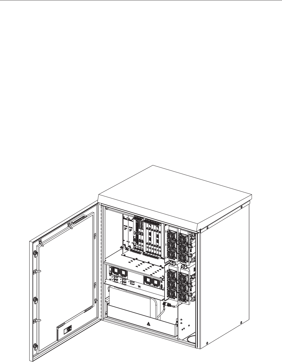
1.1 General Description
The RAN, shown in Figure 1, is the remote component in the Digivance NXD Multi-Band
Distributed Antenna System. The RAN is a pole-mounted or pad-mounted, weather-resistent
cabinet, housing electronic modules that operate on an internal cPCI backplane. Included are a
central processing unit, a system interface, an optical interface, optical to RF data converters,
RF multicouplers, and DC power supplies. The RAN also houses rectifiers, backup batteries,
power amplifiers, and optical wave division multiplexers. Optical and RF functions are both
required because the RAN exchanges data with the system Hub using an optical link and
exchanges data with wireless users using RF signals. Each RAN provides the system with an RF
antenna and can accommodate up to four bands (PCS A-F, SMR A, Cell A”/A, or Cell B/B’). Dual
RANs installed at the same location can accommodate up to eight bands using a common
antenna.
Figure 1. NXD RAN
21227-A
ADCP-75-210 • Issue 1 • November 2006
Page 2
© 2006, ADC Telecommunications, Inc.
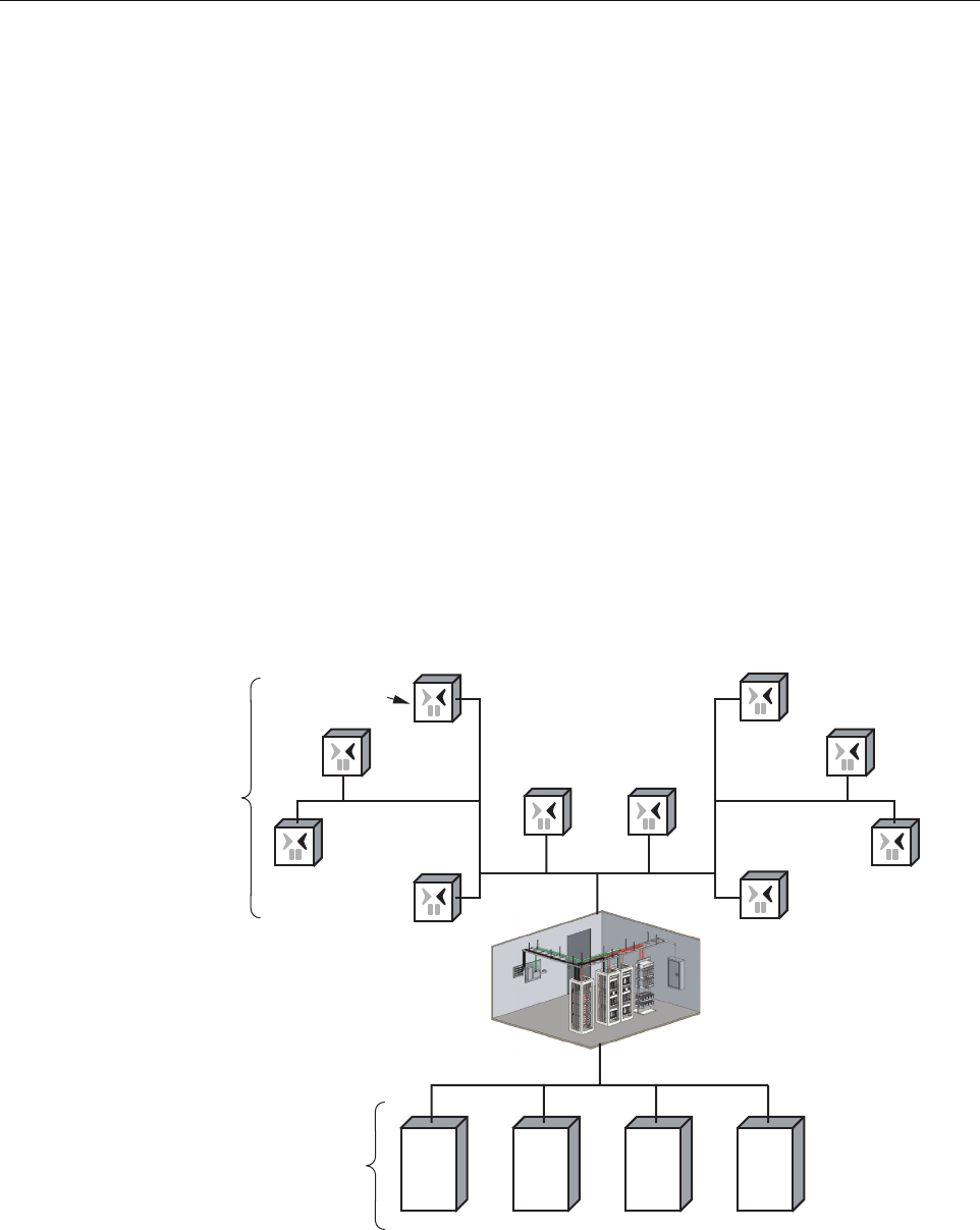
1.2 System Function
The NXD Distributed Antenna System (DAS), in which the RAN is the remote component, is a
multi-frequency, multi-protocol RF access network providing microcellular Cellular and PCS
coverage via a distributed RF access system. In a typical configuration, such as shown in
Figure 2, multiple RANs are connected to a central Hub where multiple Base Transceiver
Station (BTS) interfaces are located. Signals received at the Hub are distributed to the RANs in
digital form by way of a fiber optical link. Within the RANs, the signals are converted from
digital to RF format to be transmitted from the RAN antennas. Signals also travel in a reverse
direction, from the RANs to the Hub, with a reverse data conversion.
Physically, the DAS consists primarily of electronic modules located in the Hub and RANs. At
the Hub, these modules are mounted in an equipment rack typically housed in a common
telecommunications structure with the base station electronics for Wireless Service Providers
(WSPs), either in the same room or nearby. These modules include high power attenuators, base
station modules, a power distribution unit, an Ethernet hub, a Hub reference module, an RF
chassis, and one or more digital chassis. The RAN electronic modules, mounted in the RAN
cabinet, perform the remote system functions of optical to RF data conversion and RF access.
These modules are described in subsequent topics within this product description. Digivance
Element Management System (EMS) software, running on a computer located at the Hub,
provides a graphical user interface to monitor system performance.
Figure 2. System Function
BTS BTS BTS BTS
Distribution Hub - EMS Server,
located on Hub Master, monitors
Hub Nodes and RANs
Digital
Fiber
Radio
Access
Node
21013-A
RF
SIGNALS
WIRELESS
SERVICE
PROVIDERS
(WSPs)
ADCP-75-210 • Issue 1 • November 2006
Page 3
© 2006, ADC Telecommunications, Inc.
1.3 High-Level View
The RAN consists of the main components shown in a high-level view in Figure 3. These
components include:
•RAN Cabinet: exterior shell of the RAN containing cable connection points, ground
studs, and slots or shelves supporting other RAN components.
•RAN Chassis: standard Compact PCI (cPCI) shelf capable of housing 21 industry
standard cPCI circuit card modules. The modules are plugged into a common backplane
providing data bussing between them.
•Related Electronics: including rectifiers, Power Amplifier Assemblies (PAAs), batteries,
multiplexers, and a circuit breaker panel.
All components called out in the figure except for the multiplexers are separately installable in
the field. In most cases, however, the RAN is shipped with a basic set of components having
been ordered in advance by the customer and installed in the factory.
Figure 3. High Level View
21281-A
RAN
CABINET
RAN CHASSIS
AND ELECTRONIC
MODULES
RELATED
ELECTRONICS:
RECTIFIERS
CIRCUIT
BREAKER
PANEL
BACKUP
BATTERIES
POWER
AMPLIFIER
ASSEMBLIES
(PAAs)
MULTIPLEXERS
ADCP-75-210 • Issue 1 • November 2006
Page 4
© 2006, ADC Telecommunications, Inc.
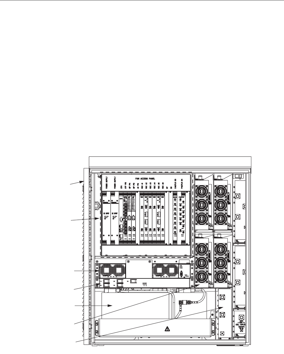
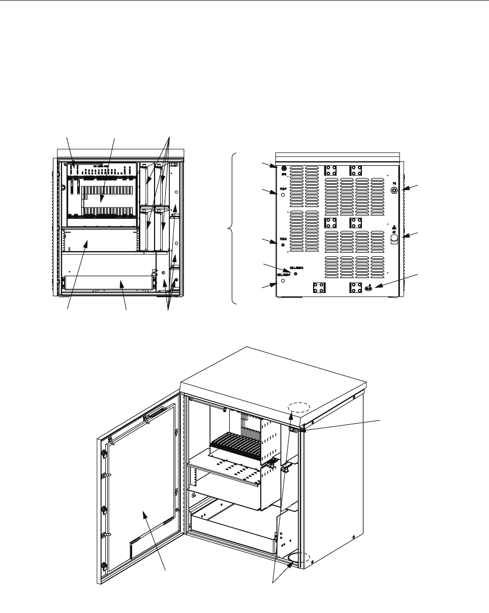
1.4 User Interface
The RAN user interface consists of the various connectors, fittings, mounting slots, power
cords, switches, and indicators that are of relevance to the user in installation and operation
procedures. The user interface is shown in Figure 4 and described in Table 1.
Figure 4. User Interface
FAN ACCESS
PANEL (1)
ELECTRONIC
MODULES (21)
POWER AMPLIFIER
ASSEMBLIES (4)
RECTIFIER
COMPARTMENT
(UP TO 3)
MUXs BATTERY
COMPARTMENT
(UP TO 4)
GPS
PCS-P
PCS-D
RF
CABLES
CELL/
SMR-D
CELL/
SMR-P
FIBER
PORT
PRIME
POWER
PORT
EARTH
GROUND
STUDS
REAR FRONT
AIR INLET
FILTER (1)
DOOR
ALARM
(1)
KNOCK-OUTS FOR
2nd RAN WIRING FROM
RAN A TO RAN B
21290-A

ADCP-75-210 • Issue 1 • November 2006
Page 5
© 2006, ADC Telecommunications, Inc.
Table 1. RAN Cabinet User Interface
COMPONENT WHY RELEVANT FOR MORE INFORMATION
Front View
Fan Access Panel Panel swings down providing access to
internal fan compartment; fans can be
replaced as required
Section 1.7.8 on Page 20
Electronic Modules Electronic modules have indicators
monitored by the user
Section 1.7 on Page 10
Electronic modules can be installed and
replaced as required
Section 4.1 on Page 57
Interconnection diagram summarizes
connections between modules
Figure 39 on Page 58;
Figure 40 on Page 59
Power Amplifier Assemblies PAAs have indicators monitored by
user
Section 1.9 on Page 25
PAAs can be installed or replaced as
required
Section 4.5 on Page 68
Rectifier Compartment Rectifiers have four unmarked LEDs Section 1.8 on Page 23
Rectifiers can be individually installed
and replaced as required
Section 4.3 on Page 66
Battery Compartment Batteries are packaged separately and
installed in a standard installation; they
can be replaced as required
Section 2.7.6 on Page 50
Rear Access
GPS, PCS-P, PCS-D,
CELL/SMR-D,
CELL/SMR-P
Connection points for RF cables con-
necting RAN with GPS antenna and RF
antenna.
Section 2.7.3 on Page 45;
Table 21 on page 47
Fiber Optic Cables Connection
Point
Connection point for fiber optic cable
from Hub
Section 2.7.4 on Page 47
Prime Power Contact Contact point for power ingress. RAN
requires 240 VAC, single phase, 20
Amps service, typically routed from a
pole- or pad-mounted junction box
Section 2.7.5 on Page 49
Earth Ground Studs Connection point for ground wires Section 2.7.2 on Page 44
Oblique View
Air Inlet Filter Filters are replaced per maintenance
schedule
Section 5.2 on Page 70
Door Alarm Replaceable switch
Knock-Outs for 2nd RAN Wir-
ing from RAN A to RAN B
When two RANs are installed at the
same location, an omnibus cable is
routed from RAN A to RAN B through
these knockout holes
Section 3 on Page 54
ADCP-75-210 • Issue 1 • November 2006
Page 6
© 2006, ADC Telecommunications, Inc.
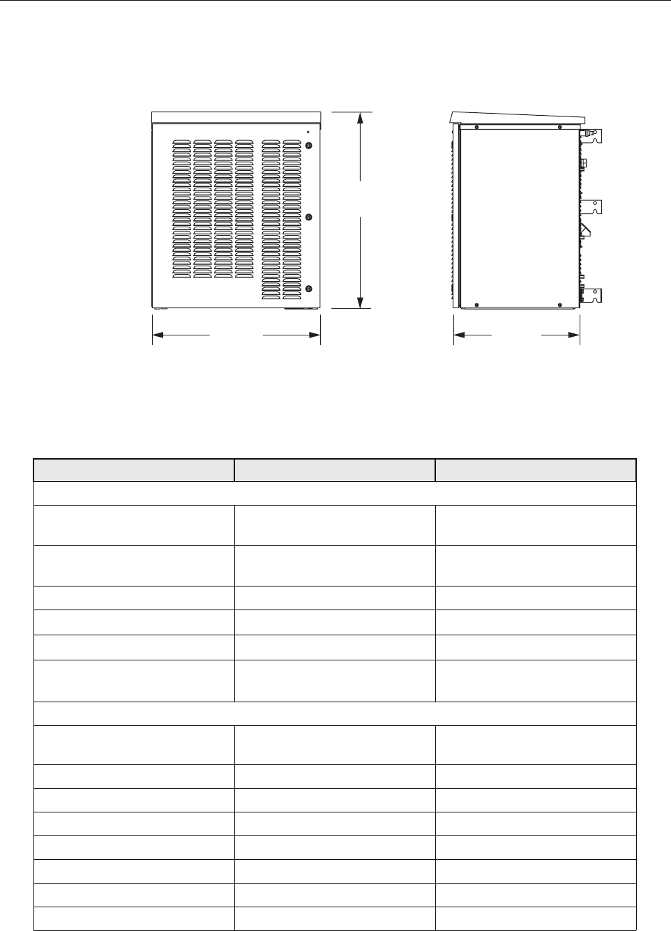
1.5 Dimensions and Specifications
Figure 5. NXD RAN Dimensions
Table 2. RAN Specifications
ITEM SPECIFICATION COMMENT
Physical and Mechanical
Dimensions (HxWxD) 36.5 x 31.0 x 24.0 inches
(92.7 x 78.7 x 60.1 cm)
See also Figure 5
Weight
with extended batteries (4)
300 lbs. (136.4 kg)
625 lbs. (284.1 kg)
RAN without batteries
Total RAN + 4 batteries
Color Putty white
Bands per box Up to 4
Boxes per RAN site Up to 2 RANs
RF connections RAN cabinet has
5 Type N plugs
Cable type: CommScope PN
540ANM or equivalent
Environmental and Thermal
Box thermal management External air Variable speed fans (PIC/PA
Assembly and cPCI)
Operating temperature -40 to +50 degrees C -40 to 122 degrees F
Cold-start temperature -20 to +50 degrees C -4 to 122 degrees F
Storage temperature -40 to +85 degrees C -40 to 185 degrees F
Internal air temperature 0 to 60 degrees C 32 to 140 degrees F
Weather resistance NEMA-3R
Operational humidity 95%
Acoustic emissions 63 dBA
21228-A
36.5 IN.
(92.7 CM)
31.0 IN.
(78.7 CM)
24.0 IN.
(60.1 CM)
FRONT SIDE

ADCP-75-210 • Issue 1 • November 2006
Page 7
© 2006, ADC Telecommunications, Inc.
Power
AC power ingress 240 VAC, 20 Amps, single phase
Battery backup options
extended
glitch
120 minutes
5 minutes
-48 volts
@25 degrees C (degrees F)
for four bands
RAN box power use 2700 Watts Max.
16 Amps Max.
cPCI rack power -48 VDC
Optical
Fiber cable ingress Nylon connector accommodates
cable diameters in range 0.38-
0.50 inches (0.97-1.27 cm).
For larger cable sizes, refer to the
note in Section 1.6.2 on Page 9.
Fiber type Corning SMF-28 or equivalent
Optical connectors LC Standard on SFP transceivers
Insertion loss 0.2 dB Typical, 0.4 dB Max.
Number of fibers required 1-4 fiber runs per RAN
Fiber configuration Star (point to point) or ring Ran ring limited to 3 SIFs
Fiber data link protocol OC-48
Wavelengths per fiber
with WDM option
with CWDM option
1 (1310 nm)
2 (1310/1550)
8 (1470-1610)
Without WDM/CWDM option
20 nm increments (ITU-GRID)
Optical transceiver type SFP Dual LC connector
Optical Tx power -3 dBm Max, -10 dBm Min. Finistar FTRJ-1320-1
(or equivalent)
Optical Rx sensitivity -22 dBm Typical, -18 dBm Max.
Optical link margin 2 dB Estimated
Optical link loss 6 dB Estimated
Optical Rx saturation level -3 dBm Min. Max. operational power
Optical Rx damage level -3 dBm Min. Max survivable power
Optical safety class 1ANSI Z 136.2
RF
Tuning frequency
PCS band
Cellular band
SMR 800 band
SMR 900 band
Receive Path
1850-1910 MHz
824-849 MHz
806-824 MHz
896-901 MHz
Transmit Path
1930-1990 MHz
869-894 MHz
851-869 MHz
935-940 MHz
Instantaneous bandwidth 15 MHz
Receiver noise figure
PCS band
Cellular band
6 dB
5 dB
Measured at Hub output connec-
tor (BIM, RxP) without BTS at 10
dB gain and a single RAN
Table 2. RAN Specifications
ITEM SPECIFICATION COMMENT

ADCP-75-210 • Issue 1 • November 2006
Page 8
© 2006, ADC Telecommunications, Inc.
1.6 RAN Cabinet
The RAN cabinet is a NEMA-3R enclosure designed to protect its electronic components from
weather and human tampering. The cabinet is weather-tight but contact with salt-air mist should
be avoided as it may decrease the mean time between failure of some components. The cabinet
has ventilation openings to allow entry of cool air and escape of hot air. The cabinet provides
termination points for the coaxial antenna cable, fiber optic cable, ground cable, and AC cable.
The cabinet has inbuilt AC power surge protection and limited storage for fiber optic cables.
1.6.1 Mounting
The RAN cabinet may be mounted on a wood pole or on a concrete pad. Mounting bracket kits
(available from ADC) are required for each type of installation.
Input IP3 -21 dBm Two tone tests at -56 dBm
Received signals
In band
Out of band +/- 8.5 MHz
Out of band +11/-13 MHz
Out of band +13/-16 MHz
-41 dBm
-3 dB
-43 dB
-83 dB
RDC capability (at cabinet input)
A/D clip level, single RF channel
Selectivity (function of SAW filter)
Selectivity
Selectivity
Automatic gain control
Detector integration time
Attack time
Decay time
Gain control range
10 usec
0 usec
0 usec
30 dB
Activated if A/D clips, changes
gain of A/D and gain in digits.
Design ensures analog gain and
digital gain change will be timed
correctly. 15 dB noise figure at
-14 dB gain
Gain in series with BTS -10 to +10 dB Lower limit for simulcast with a
host tower site, the max reduces
effect of cascaded noise figure
Gain parallel to BTS 0 to +30 dB Allows injection after BTS
amplifiers
Gain stability +/- 2dB Over temperature, frequency, and
aging valid for input signals
below AGC threshold
Gain resolution 1 dB
Gain measurement Configured at startup using fac-
tory calibration of modules and
user data
Table 2. RAN Specifications
ITEM SPECIFICATION COMMENT