ADC Telecommunications DNXSMR1A Digivance® NXD SMR 900 MHz System User Manual 75210
ADC Telecommunications Inc Digivance® NXD SMR 900 MHz System 75210
Contents
- 1. User Manual 1
- 2. User Manual 2
- 3. User Manual 3
- 4. User Manual 4
User Manual 2

ADCP-75-210 • Issue 1 • November 2006
Page 9
© 2006, ADC Telecommunications, Inc.
1.6.2 Fiber Optic Cable Entry
A nylon connector is provided on the rear of the RAN cabinet for routing a fiber optic cable into
the cabinet. The cord connector provides cable strain relief and a watertight seal at the fiber
optic cable entry point. As the connector nut is tightened, a soft neoprene bushing compresses to
tightly grip the cable without applying excessive force to the fibers. The connector
accommodates cables of a diameter in the range .38 to .50 inches (.97 to 1.27 cm).
In a typical installation, the connectorized end of a multi-fiber OSP cable is routed into the
cabinet through the cord connector and the individual fibers are connected to the optical
transceiver on the Synchronous Interface Card (SIF). Excess slack is stored inside the cabinet.
The stub end of the cable is routed to an external splice enclosure (not provided) for splicing to
the outside plant fiber optic cable.
1.6.3 Antenna Cable Connections
Five N-type plugs are provided on the rear of the RAN cabinet for connecting the antenna
coaxial cables. On the inside of the cabinet, coaxial jumper cables (included with the cabinet)
are used for connecting to the antenna port on the appropriate multiplexer.
1.6.4 AC Power Wiring Entry and Grounding
The NXD RAN uses 240 VAC power. A one inch (2.54 cm), 90 degree rigid elbow conduit
fitting is provided on the rear of the cabinet. The conduit should be routed to an external
junction box (not provided). It is suggested that an external AC outlet (not provided) be installed
near the cabinet to power test equipment and power tools. The AC source should supply 50/60
Hz, single-phase power through a circuit breaker rated at 20 Amps.
1.6.5 Ventilation
Ventilation openings are provided in the front door of the RAN cabinet to permit entry of air for
cooling. A filter removes dirt particles so that only clean air enters the cabinet. The heated air
exits the cabinet through the rear side. The four PAAs are each equipped with three cooling fans
that pull air through the module and exhaust it to the rear of the cabinet. A fan assembly at the
top of the RAN chassis forces the air out the rear side of the cabinet.
Note: If the installer has a larger cable, the manufacturer (Hubbell Inc.) makes bushings
that fit this connector in the following size ranges: .500-.625, .625-.750, .750-.875, .875-
1.00, 1.00-1.125 inches.
ADCP-75-210 • Issue 1 • November 2006
Page 10
© 2006, ADC Telecommunications, Inc.
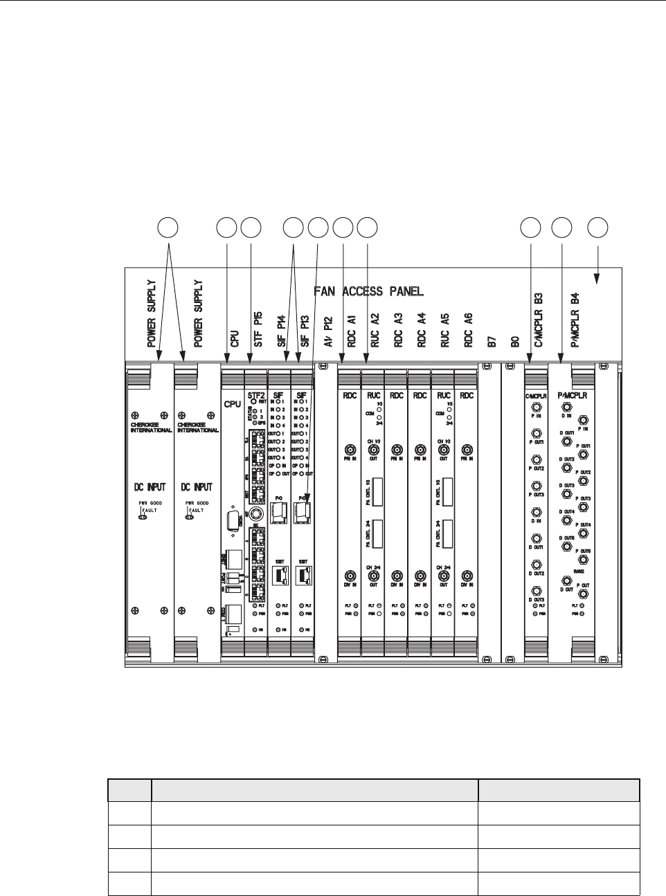
1.7 RAN Chassis and Electronic Modules
The RAN chassis, shown in Figure 6, is a standard Compact PCI (cPCI) shelf capable of
housing 21 industry standard cPCI circuit cards (called “electronic modules” in this manual).
The backplane supports the basic cPCI functions and it has been extended to allow the routing
of DIFTM, reference clocks and I2C signals between I2C modules. The RAN chassis also houses
cooling fans within the Fan Access Panel on the top of the chassis. Table 3 identifies the
electronic modules using the callout reference numbers from Figure 6.
Figure 6. RAN Chassis
Table 3. RAN Chassis Electronic Modules
REF # MODULE NAME FOR DETAILS REFER TO
1cPCI Power Supplies Section 1.7.1 on Page 12
2Central Processing Unit (CPU) Section 1.7.2 on Page 13
3System Interface (STF2) Section 1.7.3 on Page 14
4Synchronous Interface (SIF) Section 1.7.4 on Page 15
21282-A
123 67 891045
ADCP-75-210 • Issue 1 • November 2006
Page 11
© 2006, ADC Telecommunications, Inc.
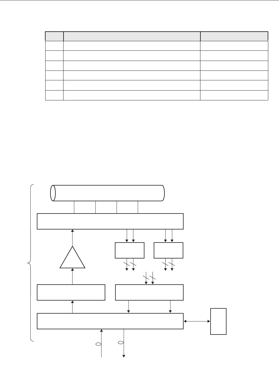
Figure 7 is a schematic showing the data flow in the RAN chassis. As shown, data flows in two
directions, from the Hub through the RAN to the antenna, and from the antenna through the
RAN back to the Hub. In each direction, data conversion occurs, with optical data
“upconverted” to RF data in the up direction in the schematic, and RF data “downconverted” to
optical data in the down direction. In an up direction, the RUC module converts Digitized
Intermediate Frequency (DIF) data into PCS, Cellular, and SMR frequency RF bands. The RF
signals are amplified and then transmitted from the RF antenna. In the down direction, the RDC
module converts PCS, Cellular, and SMR frequency bands into DIF data. The overall series of
events is managed by the CPU using an Ethernet connection to the chassis backplane.
Figure 7. RAN Chassis Schematic
5Small Form-Factor Pluggable Optical Transceiver (SFP) Section 1.7.5 on Page 17
6RAN Down Converter (RDC or RDC2) Section 1.7.6 on Page 17
7RAN Up Converter (RUC2.X or RUC3) Section 1.7.7 on Page 19
8800 MHz Multi-Coupler Section 1.7.9 on Page 20
91900 MHz Multi-Coupler Section 1.7.10 on Page 22
10 Fan Access Panel Section 1.7.8 on Page 20
Table 3. RAN Chassis Electronic Modules
REF # MODULE NAME FOR DETAILS REFER TO
SIF
MPLX
RF RF
Pri Div
Pri Div Pri Div
1900
MUL
800
MUL
DIF
DIF
RF
1900-P 1900-D 800-P 800-D
DIF
RUC RDC
CPU
Ethernet
Fiber Fiber
6 6 3 3
MCPA
RAN
HUB
MB
ANT
RAN = Radio Access Node
DIF = Digital Intermediate
Frequency
SIF = Synchronous Interface
RUC = RAN Up Converter
MCPA = Munti-Carrier Power
Amplifier
MPLX = Multi-plexer/Combiner
MB ANT = Multi Band Antenna
MUL = Multi-Coupler
RDC = RAN Down Converter
21294-A
ADCP-75-210 • Issue 1 • November 2006
Page 12
© 2006, ADC Telecommunications, Inc.
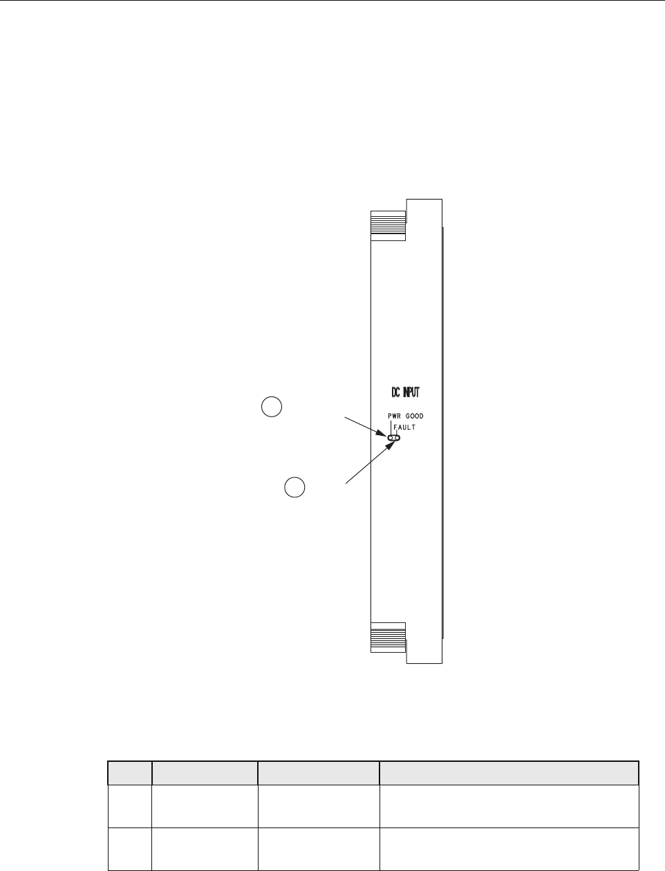
1.7.1 cPCI Power Supply Modules
The Compact PCI (cPCI) Power Supply Modules provide +/-12V, 5V, and 3.3V DC power to
the cPCI backplane for use by the cPCI electronic modules. Each RAN requires one power
supply module. Two modules can be used to provide redundancy if desired. These modules are
hot swappable. Figure 8 shows the cPCI Power Supply Module faceplate. Table 4 describes the
faceplate components called out in the figure.
Figure 8. cPCI Power Supply Module Faceplate
CPU
Table 4. cPCI Power Supply Module Faceplate
Ref # DESIGNATION DEVICE FUNCTIONAL DESCRIPTION
1PWR GOOD Single-color LED
(green)
Power Good. Turns green when module has
power
2FAULT Single-color LED
(red)
Fault. Turns red when module has
insufficient power to perform its function
21240-A
POWER
GOOD LED
FAULT
LED
1
2
ADCP-75-210 • Issue 1 • November 2006
Page 13
© 2006, ADC Telecommunications, Inc.
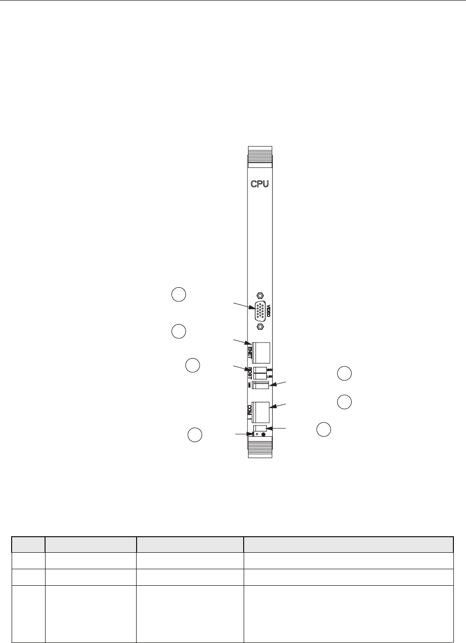
1.7.2 Central Processing Unit (CPU) Module
The Central Processing Unit (CPU) Module is a cPCI-based, single-board x86 computer with
disk running on a Linux operating system. Each RAN chassis has one CPU module. The CPU
runs a process management program that manages all RAN hardware including RF and digital
equipment. The program also manages RF signal gain and monitors signal presence and quality.
Figure 9 shows the CPU module faceplate. Table 5 describes the faceplate components called
out in the figure.
Figure 9. CPU Module Faceplate
CPU
Table 5. CPU Module Faceplate Components
REF # DESIGNATION DEVICE FUNCTIONAL DESCRIPTION
1USB1 USB connector Front panel input/output for USB connectivity
2COM 1 RJ-11C connector Front panel interface for COM1
3(Unmarked) Status LEDs LED 1 is POST (red on start-up, turns green on
successful completion of start-up self test); LED 2
& 3 are undefined; LED 4 (blinking green) indicates
disk or flash memory activitity
21251-A
VIDEO
CONNECTOR
ETHERNET
CONNECTOR
UNIVERSAL
SERIAL BUS
CONNECTOR
COM 1
CONNECTOR
STATUS
LEDs
1
7
6
5
4
2
3
ACTICITY
LEDs
RESET
BUTTON

ADCP-75-210 • Issue 1 • November 2006
Page 14
© 2006, ADC Telecommunications, Inc.
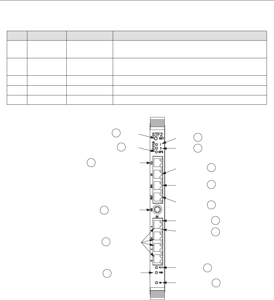
1.7.3 System Interface (STF2) Module
The System Interface (STF2) Module is a cPCI electronic module that provides the CPU and
other electronic modules with the ability to communicate with one another using the four I2C
buses on the cPCI backplane. One STF2 is used per RAN. The STF2 also has the GPS antenna
input port located in the center of the module faceplate. STF2 modules are specified according
to the number of qualifying communications devices being utilized. Table 6 describes the
module faceplate components. Figure 10 shows the location of the faceplate components.
4RST Recessed switch Reset. Used to manually reset the CPU
5POST Single-color LEDs
(yellow)
Post. Top four LEDs give status of CPU during initial
boot process; bottom four give board operation status
6ENET RJ-45 connector with
single-color LEDs (green
and yellow)
Ethernet. 10 BaseT. Connects to RJ-45 connector on
SIF module (10BT port) using cable 1001478P001.
Connection status (green) and 100 BT (yellow)
7VIDEO 15-PIN VGA connector Video. Not used by Digivance system
Table 6. System Interface Module Faceplate Components
REF # DESIGNATION DEVICE FUNCTIONAL DESCRIPTION
1RST Recessed switch Reset. Used to halt operation of the CPU operating system. A
power ON reset is required to restart the CPU
2STATUS 1 Single-color LED
(yellow)
Reserved for future use. Indicator turns yellow when the CPU is
not installed or has malfunctioned
3STATUS 2 Single-color LED
(yellow)
Reserved for future use. Indicator turns yellow when the CPU is
not installed or has malfunctioned
4STATUS GPS Single-color LED
(green)
Indicator showing that 1PPS signal is available. Led toggles once
per second (RAN only)
5DA RJ-45 connector Door Alarm. Input using cable 1001474P001; small LED on this
connector lights (red) when door is open
6GPS RJ-45 connector Not used
7RECT RJ-45 connector Rectifier. Communications to rectifier using cable 1001476P001
8(Unmarked) Single-color LED
(red)
I2C Error LEDs. One on each I2C RJ-45 connector. Indicator turns
red when there is no response on port
9(Unmarked) Single-color LED
(green)
I2C Comm LEDs. One on each I2C RJ-45 connector. Indicator
turns green when an I2C message sent on the port
10 FLT Single-color LED
(red)
Fault. Indicator turns red when module has failed or upon startup
until the module has completed initialization
Table 5. CPU Module Faceplate Components
REF # DESIGNATION DEVICE FUNCTIONAL DESCRIPTION
ADCP-75-210 • Issue 1 • November 2006
Page 15
© 2006, ADC Telecommunications, Inc.
Figure 10. System Interface Module Faceplate
1.7.4 Synchronous Interface (SIF) Module
The Synchronous Interface (SIF) Module provides the optical interface between the Hub and
the RAN. This interface provides for exchange of digitized RF signal information and 10BaseT
Ethernet command and control information. Each RAN can have up to two SIFs, each handling
two bands with diversity receive paths.
11 HS Single-color LED
(blue)
Not used
12 PWR Single-color LED
(green)
Power. Indicator turns green when module has power
13 I2C A-D RJ-45 connectors I2C (Bus). Connectors to I2C buses
14 ANT SMA connector Antenna. Input for GPS antenna signal
15 TLA RJ-45 connector Tower Light Alarm (unused)
Table 6. System Interface Module Faceplate Components
REF # DESIGNATION DEVICE FUNCTIONAL DESCRIPTION
21253-A
GPS
LED
RESET
SWITCH STATUS
LED 1
4
15
1
2
STATUS
LED 2
TOWER LIGHT
ALARM CONNECTOR DOOR ALARM
CONNECTOR
I2C
CONNECTOR
I2C COMM LED
3
5
GPS COMMS
CONNECTOR 6
RECTIFIER
COMMS
CONNECTOR
7
8
POWER LED
12
FAULT LED 10
HOT SWAP LED 11
I2C ERROR LED
9
14
13
GPS ANTENNA
CONNECTOR
(RAN ONLY)
ADCP-75-210 • Issue 1 • November 2006
Page 16
© 2006, ADC Telecommunications, Inc.
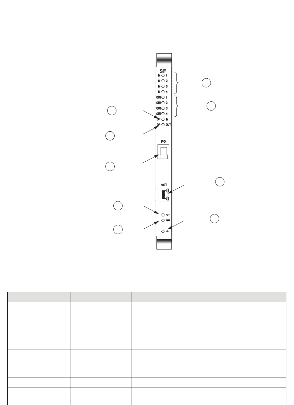
The SIF module is equipped with a small form-factor pluggable optical transceiver (SFP)
module. (For more information on the SFP, see Section 1.7.5.) Figure 11 shows the SIF module
faceplate. Table 7 describes the faceplate components.
Figure 11. Synchronous Interface Module Faceplate
Table 7. Synchronous Interface Module Faceplate Components
REF # DESIGNATION DEVICE FUNCTIONAL DESCRIPTION
1IN 1-4 Tri-color LED
(green/yellow/red)
In. Indicates if DIF input is not enabled (off), good (green),
degraded (yellow), clock issue (blinking), or no DIF tone
lock or unused channel (red)
2OUT 1-4 Tri-color LED
(green/yellow/red)
Out. Indicates if DIF output is not enabled (off), good
(green), degraded (yellow), clock issue (blinking), or bad
data on output of unused channel (red)
310BT RJ-45 connector 10BaseT (Ethernet). Communications between SIF and CPU
using cable 1001478P001
4HS Blue LED Not used
5PWR Green LED Power. Lights when module has power
6FLT Red LED Fault. Lights when module has failed and during start-up
until module is initialized
21238-A
DIF OUTPUT
LED 1-4
ETHERNET
CONNECTOR
2
3
DIF INPUT
LED 1-4 1
HOT SWAP
LED
POWER
LED
FAULT
LED
4
5
6
OPTICAL
INPUT LED
9
OPTICAL
OUTPUT LED
8
SFP FIBER
OPTIC
CONNECTOR
7
ADCP-75-210 • Issue 1 • November 2006
Page 17
© 2006, ADC Telecommunications, Inc.
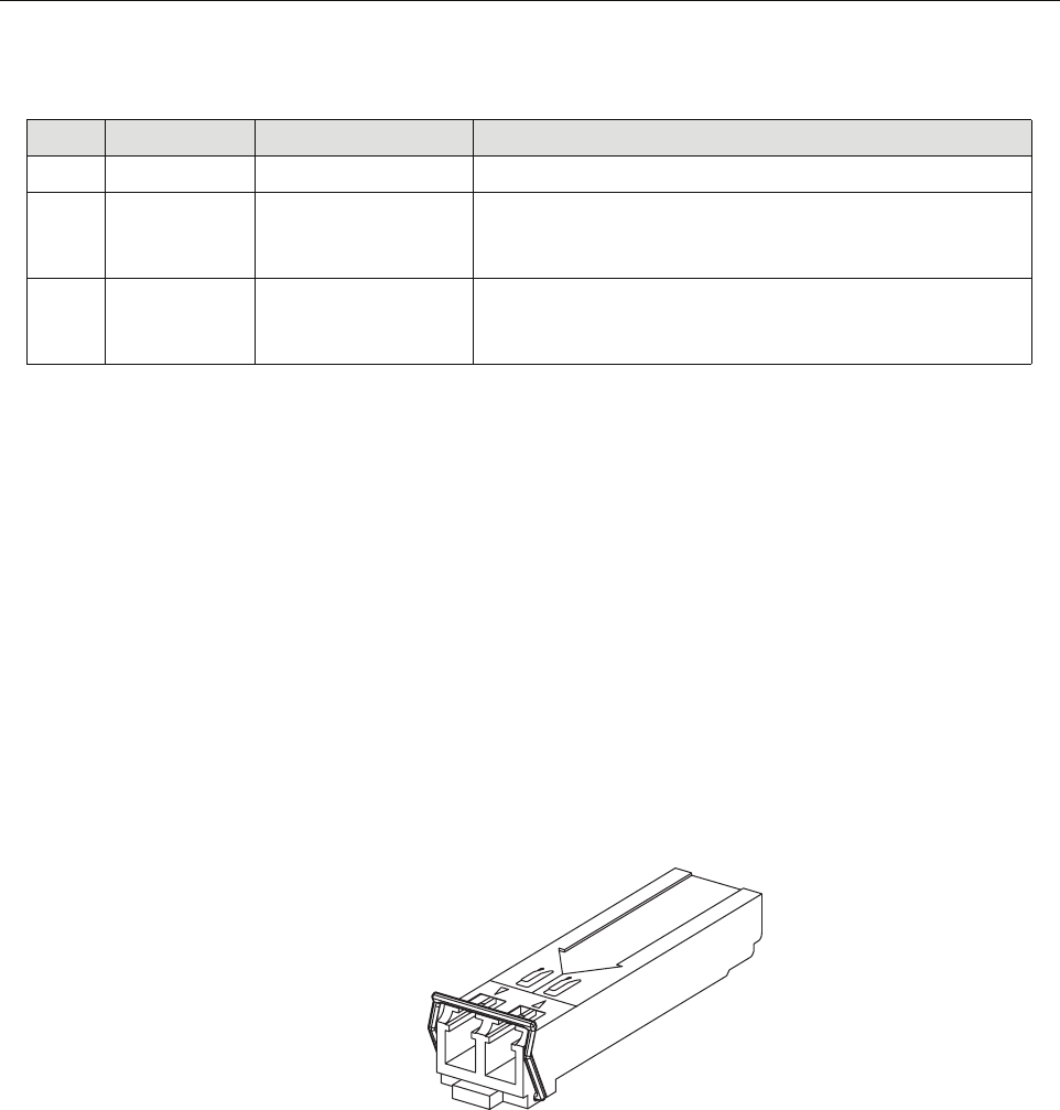
1.7.5 Small Form-Factor Pluggable (SFP) Optical Transceiver
The Small Form-Factor Pluggable (SFP) Optical Transceiver, located on the SIF module and
shown in Figure 12, provides the optical interface between the Hub equipment and the RAN
hardware. The SFP has a laser transmitter and an optical receive detector.
The Digivance NXD system uses industry standard SFP optics which offer a number of
configuration options depending on the requirements of the project. The SFP modules are
available separately and may or may not be installed in the SIF depending on the configuration
ordered. The SFP module is specified as up to two per RAN and is able to support two bands
with receive diversity.
The standard SFP module has an optical budget of 9 dB. The SFP module is factory and field
replaceable with optical transceivers having extended optical budgets up to 26 dB or Coarse
Wave-Division Multiplexing (CWDM) optical wavelengths.
Figure 12. Small Form-Factor Optical Transceiver
1.7.6 RAN Down Converter (RDC or RDC2) Module
The RAN Down Converter (RDC or RDC2) Module is a cPCI electronic module housing a
dual-diversity wideband RF receiver. This module takes PCS, Cellular, SMR A, and SMR B
signals from a primary and secondary antenna (via the appropriate multicoupler) and converts
the signals to Digitized Intermediate Frequency (DIF).
7F/O Dual-LC connectors Fiber/Optics. Optics connector on SFP optical transceiver
8OP IN Tri-color LED
(green/yellow/red)
Optical In. Indicates input status of the SFP interface: not
enabled (off), good (green), degraded (yellow), or bad output
signals (red)
9OP OUT Tri-color LED
(green/yellow/red)
Optical Out. Indicates output status of SFP interface: not
enabled (off), good (green), degraded (yellow), or bad fram-
ing, bad parity, no signal, or no signal lock (red)
Table 7. Synchronous Interface Module Faceplate Components
REF # DESIGNATION DEVICE FUNCTIONAL DESCRIPTION
21316-A
ADCP-75-210 • Issue 1 • November 2006
Page 18
© 2006, ADC Telecommunications, Inc.
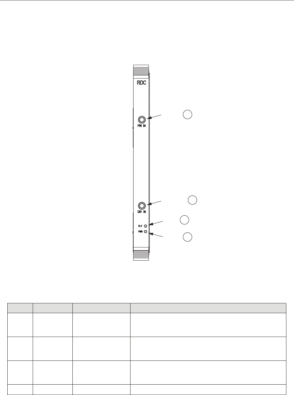
This module also provides a CW test tone for use in reverse continuity testing. The RF signals
are input into the module by way of coax cables terminated with SMA connectors on the
faceplate (at the ports labeled PRI IN and DIV IN). Figure 13 shows the module faceplate.
Table 8 describes the module faceplate components called out in the figure.
Figure 13. RAN Down Converter Module Faceplate
Table 8. RAN Down Converter Module Faceplate Components
REF # DESIGNATION DEVICE FUNCTIONAL DESCRIPTION
1PRI IN SMA connector Primary In. Receives RF primary output from either C/PMC-
PLR or P/MCPLR module. Connection is made using cable
1955000P081
2DIV IN SMA connector Diversity In. Receives RF diversity output from either C/
PMCPLR or P/MCPLR module. Connection is made using
cable 1955000P081
3FLT Red LED Fault. Lights when module has failed and during start-up until
module has initialized; blinks after module receives a system
clock and is awaiting initialization
4PWR Green LED Power. Lights when module has power
21236-A
PRIMARY
IN
DIVERSITY
IN
FAULT
LED
POWER
LED
1
2
3
4
ADCP-75-210 • Issue 1 • November 2006
Page 19
© 2006, ADC Telecommunications, Inc.
1.7.7 RAN Up Converter (RUC2.X or RUC3) Module
The RAN Up Converter (RUC2.X or RUC3) Module is a cPCI electronic module that takes
Digitized Intermediate Frequency (DIF) signals from a DIF signal generated by the SIF and
converts the signals to RF (PCS, Cellular, SMR A, and SMR B frequency bands). Each module
supports two simultaneous bands via wideband outputs. The RUC also provides clocking for its
neighboring RDC. For module faceplate and callouts, see Figure 14 and Table 9.
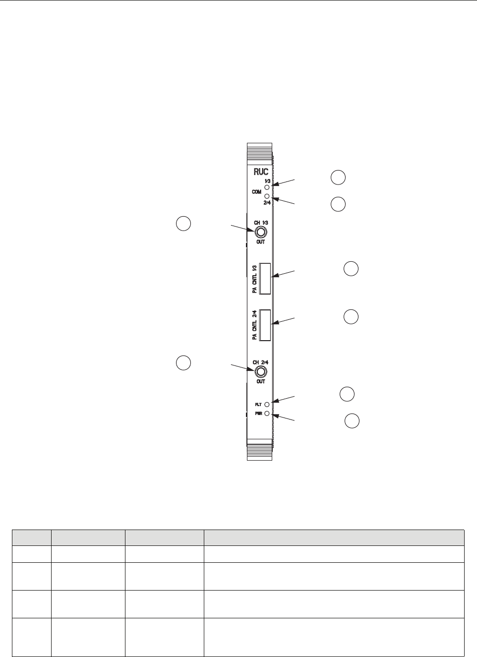
Figure 14. RAN Up Converter Module Faceplate
Table 9. RAN Up Converter Module Faceplate Components
REF # DESIGNATION DEVICE FUNCTIONAL DESCRIPTION
1CH 1/3 OUT SMA connector Channel 1/3 Out*
2COM 1/3 Yellow LED COM Port 1/3. Turns yellow when DIF is locked to SIF channel
1 or 3*
3COM 2/4 Yellow LED COM Port 2/4. Turns yellow when DIF is locked to SIF channel
2 or 4*
4PA CNTL 1/3 I2C flatpack
connector
PA Control Channel 1 or 3. Outputs control data to the PIC card
on the PAA for the channel being provided (using cable
1955000P079)*
21234-A
CHANNEL
1/3 OUT
COM 1/3
1
2
COM 2/4 3
CHANNEL
2/4 OUT
8
FAULT LED 6
POWER LED 7
PA CNTL 1/3 4
PA CNTL 2/4 5
ADCP-75-210 • Issue 1 • November 2006
Page 20
© 2006, ADC Telecommunications, Inc.
* An RUC in slot A2 will connect to PAAs 1 and 2. An RUC in slot A5 will connect to PAAs 3 and 4.
Therefore, the RUC front panel indicators of 1/3 and 2/4 will map to PAAs 1 and 2 connections in slot
A2 and PAA 3 and 4 connections in slot A5.
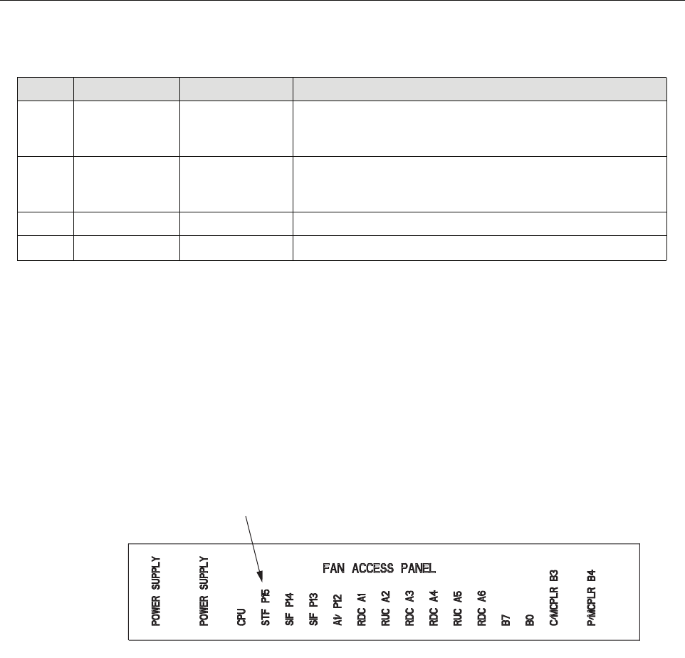
1.7.8 Fan Access Panel
The Fan Access Panel, shown in Figure 15, has a hinged front panel that swings down providing
access to the two fans cooling the RAN chassis. These fans are user-replaceable. This panel has
labels identifying the electronic modules located in the cPCI shelf below the panel.
Figure 15. Fan Access Panel
1.7.9 800 MHz Multicoupler (C/MCPLR)
The 800 MHz (C/MCPLR) Module is a cPCI electronic module that houses the dual-diversity,
receive unit for the 800 MHz bands. This module interfaces to the multiplexer system and
contains the front end low noise amplifiers for the reverse path. The module has six outputs
(Cell bands A, B, and 800 MHz, with diversity).
Figure 16 shows the location of the faceplate components. Table 10 describes the faceplate
components.
5PA CNTL 2/4 I2C flatpack
connector
PA Control Channel 2 or 4. Outputs control data to the PIC card
on the PAA for the channel being provided (using cable
1955000P079)*
6FLT Red LED Fault. Turns red when the module has failed. Indicator is lit dur-
ing start-up until module has initialized. Indicator will blink
after module receives system clock and is awaiting initialization
7PWR Green LED Power. Turns green when module has power
8CH 2/4 OUT SMA connector Channel 2 or 4 OUT*
Table 9. RAN Up Converter Module Faceplate Components
REF # DESIGNATION DEVICE FUNCTIONAL DESCRIPTION
21318-A
LABELS FOR CPCI
ELECTRONIC MODULES
ADCP-75-210 • Issue 1 • November 2006
Page 21
© 2006, ADC Telecommunications, Inc.
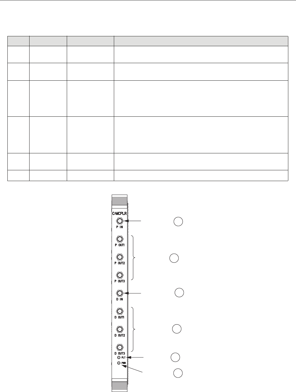
Figure 16. C/MCPLR Module Faceplate
Table 10. C/MCPLR Modules Faceplate Components
REF # DESIGNATION DEVICE FUNCTIONAL DESCRIPTION
1P IN SMA connector Primary In. Receives RF primary reverse path input from primary
antenna
2D IN SMA connector Diversity In. Receives RF diversity reverse path input from second-
ary antenna
3P OUT SMA connectors Primary Out. 3 primary outputs (Cell bands A, B, and SMR-A). Each
output being used connects to one RDC electronic module, either in
the same RAN or in the extension RAN if present. Connection is
made using cable 1955000P081
4D OUT SMA connectors Diversity Out. 3 diversity outputs (Cell bands A, B, and SMR-A).
Each output being used connects to one RDC electronic module,
either in the same RAN or in the extension RAN if present. Connec-
tion is made using cable 1955000P081
5FLT Red LED Fault. Lights when module has failed and during start-up until mod-
ule has initialized
6PWR Green LED Power. Lights when module has power
21242-A
2
1
3
5
6
4
DIVERSITY IN
CONNECTOR
PRIMARY IN
CONNECTOR
PRIMARY OUT
CONNECTORS
DIVERSITY OUT
CONNECTORS
FAULT LED
POWER LED
ADCP-75-210 • Issue 1 • November 2006
Page 22
© 2006, ADC Telecommunications, Inc.
1.7.10 1900 MHz Multicoupler (P/MCPLR)
The 1900 MHz (P/MCPLR) Module is a cPCI electronic module that houses the dual-diversity,
receive unit for the PCS band. This module interfaces to the multiplexer system and contains the
front end low noise amplifiers for the reverse path. The PCS band has 12 outputs (bands A-F,
with diversity). Figure 17 shows the location of the faceplate components. Table 11 describes
the module faceplate components.
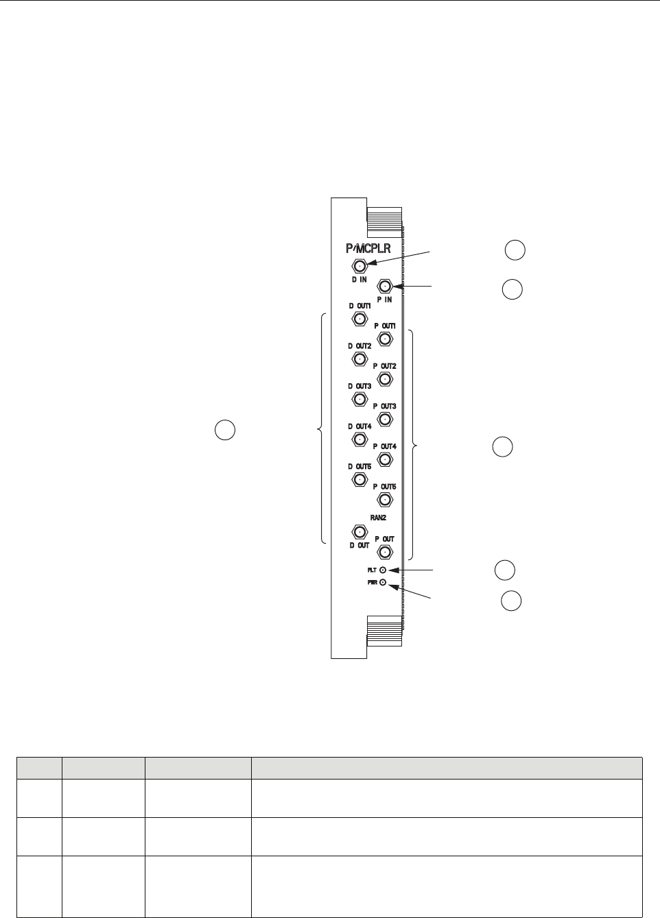
Figure 17. P/MCPLR Modules Faceplates
Table 11. P/MCPLR Modules Faceplate Components
REF # DESIGNATION DEVICE FUNCTIONAL DESCRIPTION
1P IN SMA connector Primary In. Receives RF primary reverse path input from primary
antenna
2D IN SMA connector Diversity In. Receives RF diversity reverse path input from secondary
antenna
3P OUT SMA connectors Primary Out. 6 primary outputs (bands A-F); each output being used
connects to one RDC module, in either same RAN or extension RAN
if present. Connection is made using cable 1955000P081
21245-A
2
1
3
5
6
4
DIVERSITY IN
CONNECTOR
PRIMARY IN
CONNECTOR
PRIMARY OUT
CONNECTORS
DIVERSITY OUT
CONNECTORS
FAULT LED
POWER LED
ADCP-75-210 • Issue 1 • November 2006
Page 23
© 2006, ADC Telecommunications, Inc.
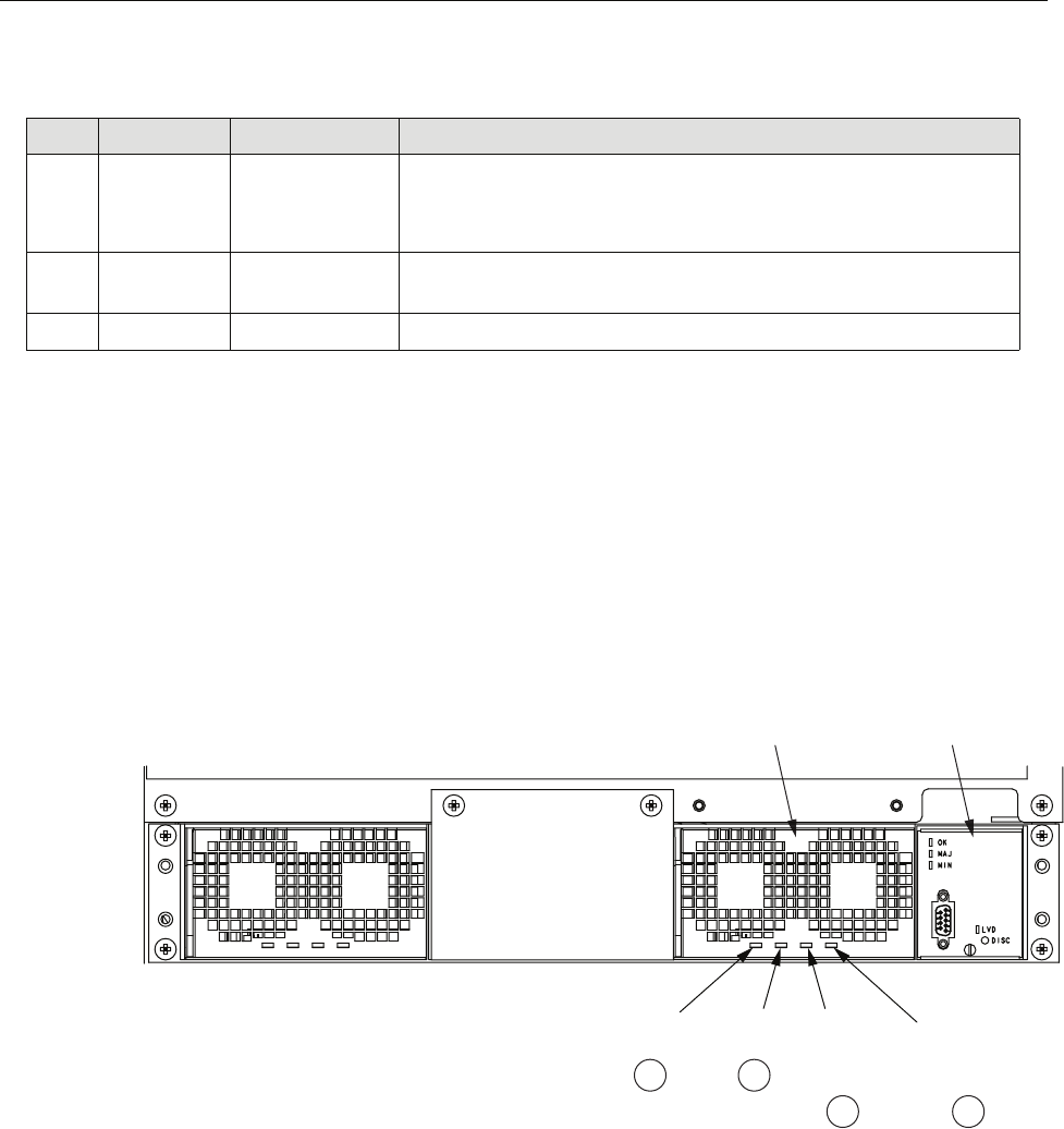
1.8 Rectifier Shelf
The Rectifier Shelf, shown in Figure 18, is a chassis/backplane device that contains rectifier
modules and a Low Voltage Disconnect (LVD) unit. The shelf interconnects the rectifier
modules and LVD unit, and provides an interface to external connectors.
Typically, the rectifier shelf contains two rectifier modules. The center panel on the shelf can be
removed to add a third rectifier, providing N+ redundancy as more equipment is added to the
RAN chassis.
Figure 18. Rectifier Shelf
1.8.1 Rectifier Module
The rectifier module converts 240 VAC prime power into -48 VDC for use within the RAN.
Each rectifier has four LEDs, shown in Figure 18 and described in Table 12. The rectifiers are
controlled by the LVD unit under command of the STF2 module.
4D OUT SMA connectors Diversity Out. 6 diversity outputs (bands A-F); each output being
used connects on one RDC module, in either same RAN or extension
RAN if present. Connection is made using cable 1955000P081
5FLT Red LED Fault. Lights when module has failed and during start-up until mod-
ule has initialized
6PWR Green LED Power. Lights when module has power
Table 11. P/MCPLR Modules Faceplate Components
REF # DESIGNATION DEVICE FUNCTIONAL DESCRIPTION
21319-A
21
34
OVER
VOLTAGE
PROTECTION
LED
DC OK
LED
AC OK
LED
OVER
TEMPERATURE
PROTECTION
LED
RECTIFIER
LOW VOLTAGE
DISCONNECT
(LVD) UNIT
ADCP-75-210 • Issue 1 • November 2006
Page 24
© 2006, ADC Telecommunications, Inc.
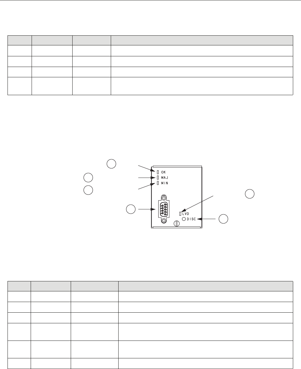
1.8.2 Low Voltage Disconnect (LVD) Unit
The Low Voltage Disconnect (LVD) Unit (Figure 19) disconnects power automatically when
the RAN voltage falls below a specified minimum. The LVD unit also manages the backup
batteries (extended or glitch).
Figure 19. Low Voltage Disconnect Unit
Table 12. Rectifier Indicators
REF # DESIGNATION DEVICE FUNCTIONAL DESCRIPTION
1(Unmarked) Green LED AC OK. Lights when AC power is present
2(Unmarked) Green LED DC OK. Lights when rectifier is limiting current
3(Unmarked) Red LED Over Voltage Protection. Lights when rectifier has failed
4(Unmarked) Red LED Over Temperature Protection. Lights when over temperature compen-
sation circuit is active
Table 13. LVD Indicators
REF # DESIGNATION DEVICE FUNCTIONAL DESCRIPTION
1OK Green LED Okay. Lights when power system is functioning correctly
2MAJ Red LED Major Fault. Lights when a major fault exists
3MIN Yellow LED Minor Fault. Lights when a minor fault exists
4(Unmarked) 9-pin connector Connector for cable 1001476P001 to the RECT (RJ45 connector)
port on the STF module
5LVD Red LED Low Voltage Disconnect. Lights when switch has closed due to low
voltage
6DISC Switch Disconnect. Pressing this switch disconnects the backup batteries
1
2
3
4
6
5
OK LED
MAJOR FAULT LED
MINOR FAULT LED LVD ON LED
21334-A
ADCP-75-210 • Issue 1 • November 2006
Page 25
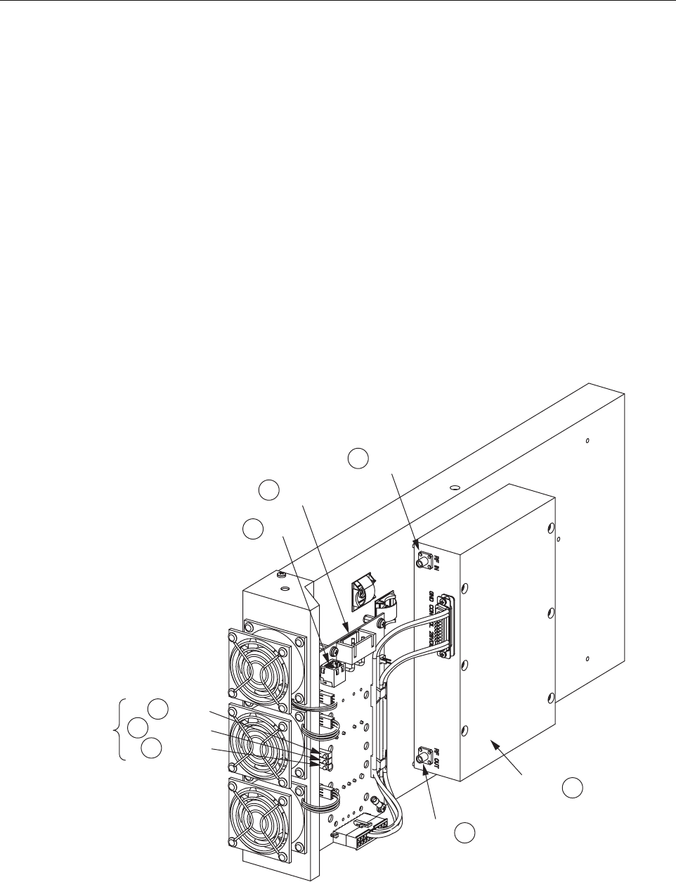
1.9 Power Amplifier Assembly
The Power Amplifier Assembly (PAA) is an electronic device that amplifies RF signals in the
forward path just before they are transmitted to the RAN antenna. Up to four PAAs may be
mounted in the RAN, each providing one band. Each PAA consists of a Power Amplifier (PA), a
control board called the PA Interface Controller (PIC), and a cooling system. The PA is multi-
channel. Different units are used for PCS, Cellular, and SMR 800 bands.
The PIC interfaces to the discrete signals of the PA. The PIC also provides DC power to the PA
by converting from -48 VDC to +12 VDC or +28 VDC depending upon which PA is being used.
Each PA has its own PIC. The PIC is managed is managed by the CPU over an I2C connection
through its corresponding RUC. The cooling system consists of a heat sink and three fans that
provide cooling for the PA by blowing external air across the heat sink. The fans are software-
controlled. The PIC module monitors the tachometer outputs of the fan.
Figure 20 shows the PA assembly connection points and indicators. Table 14 describes the items
called out in the figure.
Figure 20. Power Amplifier Assembly
DC_ IN
DC_ OUT
DC_ FAULT
PIC LED
INDICATORS
12C
48V
PWR
RF
OUT
POWER
AMPLIFIER
21276-A
5
RF IN
8
4
7
6
1
2
3

ADCP-75-210 • Issue 1 • November 2006
Page 26
© 2006, ADC Telecommunications, Inc.
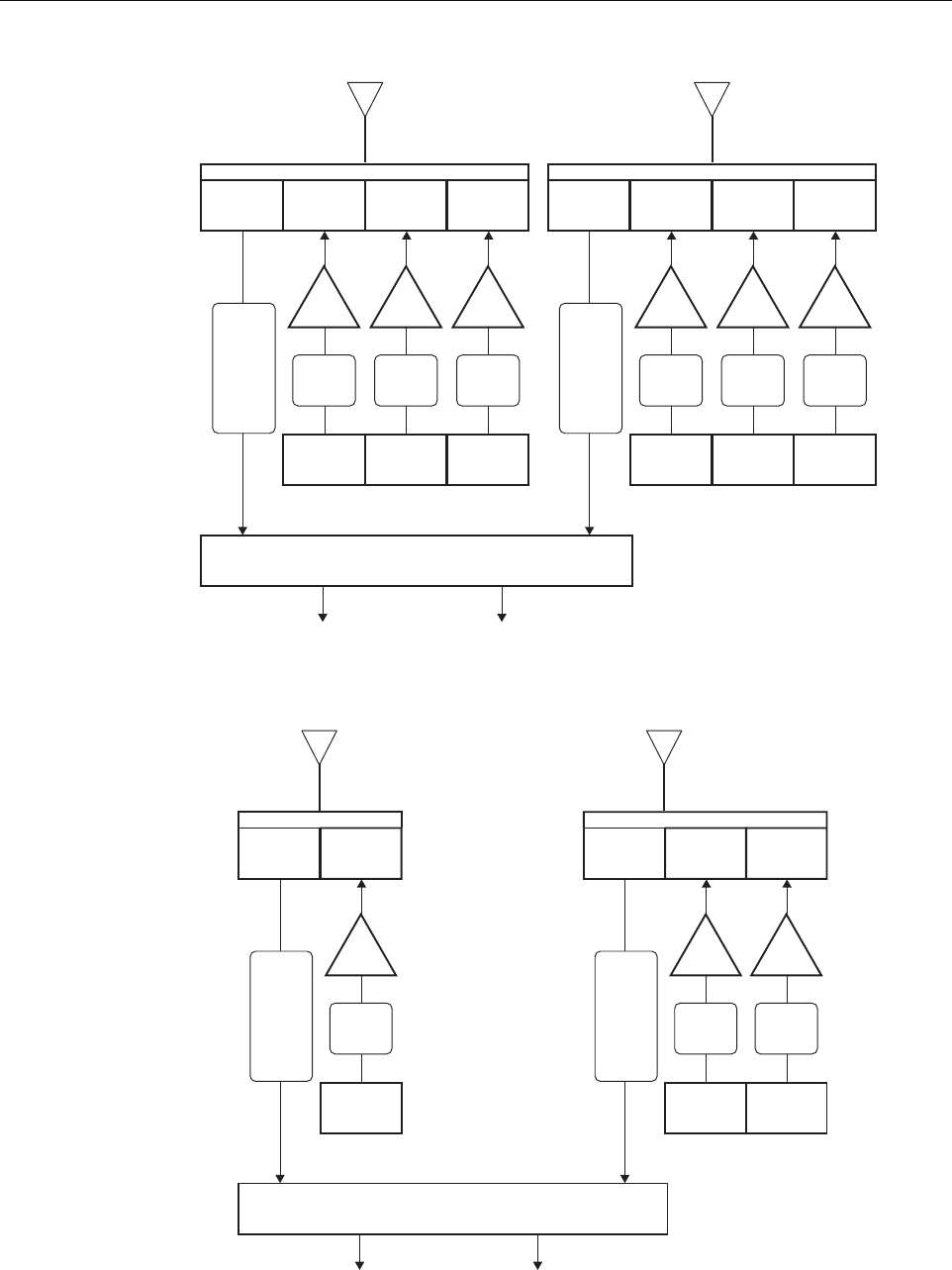
1.10 Multiplexer System
The NXD RAN multiplexer system consists of four units that interface to the antenna, PAs, and
multicouplers. There are four types found in found in every RAN:
• Quadplexer Primary (PCS Bands A, B, F), interfaces to PCS primary antenna;
• Quadplexer Diversity (PCS Bands D, E, C), interfaces to PCS diversity antenna;
• Triplexer Primary (Cellular Band B, SMR800 band), interfaces to 800 MHz primary
antenna;
• Diplexer Diversity (Cellular Band A), interfaces to 800 MHz diversity antenna.
For a schematic of the PCS multiplexers, see Figure 21. For a schematic of the Cellular/SMR
multiplexers, see Figure 22.
Table 14. PAA Connection Points and Indicators
REF # DESIGNATION DEVICE FUNCTIONAL DESCRIPTION
1DC_IN Green LED DC In. Lighted when PIC has -48 VDC input
2PA_FAULT Red LED PA Fault. Lighted when PA has failed
3DC_OUT Green LED DC Out. Lighted when PIC has +28 VDC output
4I2C RJ-45 connector
(J1)
I2C (Bus). Connection to RUC module P/A CNTRL using
cable 1001475P001
548V PWR Positronic 3-pin
connector (J2)
48 Volt DC Power. Input to PIC for -48 VDC using PIC
power harness 1001471P001
6RF OUT SMA connector RF Out. Output of PA for cable 1955000P080 to one of the
four plexers (depending on band), connector port TX
7(Unmarked) Power Amplifier Power amplifier (see description on preceding page)
8RF IN SMA connector RF In. Input from RUC for cable 19559999P079
ADCP-75-210 • Issue 1 • November 2006
Page 27
© 2006, ADC Telecommunications, Inc.
Figure 21. PCS Multiplexers
Figure 22. Cellular/SMR Multiplexers
RUC
Tx
A
MCPA
RUC
Tx
B
MCPA
RUC
Rx
1850-1910
Tx
1950-1965
Tx
1930-1945
Tx
1970-1975
Tx
F
MCPA
Primary
Antenna
Diversity
Antenna
Quadplexer
PCS Band
A/B/F
Quadplexer
PCS Band
D/E/C
Rx
A
B
C
D
E
F
Primary
RUC
Tx
D
MCPA
RUC
Tx
E
MCPA
RUC
Rx
1850-1910
Tx
1965-1970
Tx
1945-1950
Tx
1975-1990
Tx
C
MCPA
Rx
A
B
C
D
E
F
Diversity
Antenna Assembly
Multicoupler
1850/1910
21270-A
RUC
Tx
A” A
MCPA
Rx
810-849
Tx
869-880
Primary
Antenna
Duplexer
800 Mhz Band
Rx
SMR
A”
A
B
B’
Antenna Assembly
Multicoupler
810-849
21271-A
RUC
Tx
SMR-A
MCPA
Rx
810-849
Tx
855-866
RUC
Tx
B B’
MCPA
Tx
880-894
Diversity
Antenna
Triplexer
800 Mhz Band
Rx
SMR
A”
A
B
ADCP-75-210 • Issue 1 • November 2006
Page 28
© 2006, ADC Telecommunications, Inc.
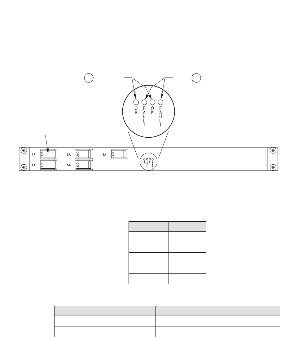
1.11 Circuit Breaker Panel
The Circuit Breaker Panel, shown in Figure 23, contains five circuit breakers. It distributes the
RAN’s -48 VDC power and protects the RAN’s electronics. Table 15 gives the circuit breaker
functions. Table 16 describes the panel LEDs.
Figure 23. Circuit Breaker Panel
1.12 Backup Batteries
The NXD RAN has two backup battery options:
• Extended Batteries: provide backup protection for up to two hours. These are four 12V,
85-100 AH internal batteries connected in series for a -48V system. The four batteries
together with associated wiring and hardware weigh 325 pounds (147.7 kg).
Table 15. Circuit Breaker Functions
BREAKER FUNCTION
1A PA1
2A PA2
3A PA3
4A PA4
5A cPCI chassis
Table 16. Circuit Breaker Panel LEDs
REF # DESIGNATION DEVICE FUNCTIONAL DESCRIPTION
1OK Green LED Okay. Lights when AC power is present
2FAULT Red LED Fault. Lights when rectifier is limiting current
21320-A
12
SYSTEM OK
LEDs
FAULT
LEDs
CIRCUIT
BREAKER
(5 PLACES)

ADCP-75-210 • Issue 1 • November 2006
Page 29
© 2006, ADC Telecommunications, Inc.
• Glitch Batteries: provide backup protection for up to five minutes. These are small,
motorcycle type batteries connected in a series configuration.
1.13 Antenna
ADC provides a pole-mount antenna kit for use when the RAN is mounted on a wooden utility
pole. The kit must be separately ordered from the RAN. Pole mounting is the most common
type of RAN installation.
The antenna offered interfaces with the PCS and Cellular/SMR bands and supports two branch
diversity receive paths. Also included in the kit is the GPS antenna used by the RAN.
The RAN may also be mounted outdoors on a concrete pad. This type of installation may use a
conventional directional antenna in either a sector or quasi-omni antenna configuration,
depending on the coverage objective and design. Proper antenna selection and the mounting
installation are the responsibility of the design engineer.
Antenna installation is covered in separate publications, available for downloading from the
ADC web site, www.adc.com. Refer to RELATED PUBLICATIONS on Page vii.
2 STANDARD INSTALLATION PROCEDURES
This section provides the standard procedures for a typical installation. The RAN may be
installed either on a wooden pole or on a concrete pad.
This section is organized as follows:
• Sections 2-1 through 2-4 provide information that is relevant before installing the cabinet.
These subsections contain an installation overview, unpacking instructions, a list of
required material and tools, and site preparation guidelines.
• Section 2-5 tells how to install a cabinet on a wooden utility pole. Included are instructions
for installing the pole mount bracket and then installing the cabinet on the bracket. Also
included are instructions for installing the rain shields.
• Section 2-6 tells how to install the RAN on a concrete pad. Included are instructions for
pouring the concrete pad, mounting the RAN on the pad, and installing the pedestal
enclosure.
• Section 2-7 contains other standard procedures typically done at every installation. These
procedures describe how to install the solar shield, grounding wire, RF cables, fiber optic
cable, AC power, and backup batteries.
Installation of the RAN cabinet may proceed separately from the installation of the
corresponding Hub equipment. When the installation of the RAN is completed, refer to the
Note: Section 3 contains instructions for installing a second RAN at the same location.
Section 4 provides information on non-standard installation procedures such as installing
an electronic module.

ADCP-75-210 • Issue 1 • November 2006
Page 30
© 2006, ADC Telecommunications, Inc.
Digivance NXD Multi-Band Distributed Antenna System Operation Manual (ADCP-75-209)
for system turn-up and test procedures.
The procedures in this section assume that the required Outside Plant (OSP) fiber optic cable
has already been routed between the Hub and the RAN, that the required antenna has been
installed, and that a coaxial cable terminated with an N-type connector has been routed to the
RAN from the antenna.
2.1 Installation Overview
A standard (typical) installation of the RAN consists of the following steps:
1. Checking out and preparing the installation site.
2. Unpacking and inspecting the shipped items.
3. Installing a pole mount frame or pedestal mount.
4. Installing the RAN cabinet on the pole or pad.
5. Installing the rain shields (pole mount) or pedestal enclosure (pad mount).
6. Installing the solar shield.
7. Installing a ground wire.
8. Connecting RF cables between the antenna and RAN.
9. Installing the fiber optical cable that connects the RAN to the Hub.
10. Installing AC power.
11. Installing backup batteries in the cabinet.
Danger: Wet conditions increase the potential for receiving an electrical shock when installing
or using electrically-powered equipment. To prevent electrical shock, never install or use
electrical equipment in a wet location or during a lightning storm.
Caution: Always allow sufficient fiber length to permit routing of patch cords and pigtails
without severe bends. Some fiber optic patch cords or pigtails may be permanently damaged if
bent or curved to a radius of less than 2 inches (50 mm).
Warning: Electronic components can be damaged by static electrical discharge. To prevent
ESD damage, always wear an ESD wrist strap when handling electronic components.
Note: To insure that all optical connectors and optical ports remain dust-free during
installation, leave all dust caps and dust protectors in place until directed to remove them
for installation.

ADCP-75-210 • Issue 1 • November 2006
Page 31
© 2006, ADC Telecommunications, Inc.
2.2 Unpacking and Inspection
The RAN is shipped to the field pre-configured with all modules and components that the
customer has ordered. Electronic modules except for the batteries are shipped already installed
in the cabinet.
The following optional accessories may also be shipped with the RAN:
• Back-up batteries
• Non-standard SFP optical transceiver
Use the following procedure to unpack and inspect the RAN components:
1. Open the shipping cartons and carefully unpack each component from the protective
packing material.
2. Check each component for broken or missing parts. If there are damages, contact ADC for
an RMA (Return Material Authorization) and to reorder if replacement is required. For
contact information, refer to Section 6 on Page 72.
2.3 Required Materials and Tools
The following materials must be supplied by the installer:
• (Pole mount only) Three galvanized steel square headed bolts with minimum tensile
strength of 20,050 lbs., 3/4 in. diameter, and of a length appropriate to pole diameter;
Three nuts for bolts, three flat washers, three split ring washers, and three 3-in. square
curved washers (see Figure 26 on Page 39)
• (Pad mount only) Four 1/2 in. diameter galvanized steel bolts with four lock washers, four
flat washers, and four concrete anchors (see Figure 28 on Page 41)
• 3M 8426-9M cold shrink
• 3M Skothkote Electrical Coating 14853
• Ten Type N plugs (CommScope PN: 540ANM or equivalent)
• Coaxial cable (CommScope PN: FXL540OPE or equivalent)
• Electrician’s tape
• Water seal
• Electrical conduit
• Conduit fittings
• Connector sealant material
• Panduit LLCF6-14B-L or equivalent (X2)
• Two-hole compression lug terminal for #6 AWG wire
• Ground rod
• Connector for attaching #6 AWG grounding wire to approved ground source

ADCP-75-210 • Issue 1 • November 2006
Page 32
© 2006, ADC Telecommunications, Inc.
The following tools are required to perform this procedure:
• Torque wrench
• Drill
• Drill bit (appropriate for pole width and 3/4 in. bolts)
• 7/16 in. open-end wrench
• Compression pliers for #6 AWG grounding lug
• Wire cutters
• Wire strippers
• Conduit cutter
• Conduit bender
2.4 Site Preparation
This section describes site preparation for installation and is presented only as a guideline for a
typical RAN installation.
2.4.1 Space Requirements
When an installation site for the RAN is selected, either on a utility pole or concrete pad, care
must be exercised to ensure that the site provides adequate space and clearance to accommodate
the current installation and any future upgrades. Table 17 gives RAN dimensions.
2.4.2 Power Requirements
Power must be available at the RAN site. The RAN requires 240 VAC, single phase, 20 Amps
service. Included with the power meter must be surge protection and circuit breakers.
The RAN can have up to three 1500 watt rectifiers. For the minimum specified voltage (176
VAC), each can draw up to 10 amps. The RAN will draw up to 1800 watts normally, but when
batteries are re-charging that amount will increase the current draw into a RAN to up to 16
Amps. Therefore, one 20 Amps service is required per four band RAN.
Table 17. RAN Dimensions
CONFIGURATION WIDTH HEIGHT DEPTH
RAN 31.35 in. (76.7 cm) 36.5 in. (92.7 cm) 27.5 in. (69.9 cm)
Dual RAN 31.25 in. (76.7 cm) 72 in. (182.9 cm) 27.5 in. (69.9 cm)

ADCP-75-210 • Issue 1 • November 2006
Page 33
© 2006, ADC Telecommunications, Inc.
In a pole mount installation, the power meter is typically installed on the pole below the unit in
separate boxes. In a concrete pad installation, an external junction box is typically placed near
the RAN providing AC power, surge protection, and circuit breakers.
2.4.3 Antenna Requirement
ADC offers a pole-mount antenna kit (accessory) for use when the RAN is mounted on a
wooden utility pole. Either a 2 in. (5.08 cm) O.D. model or a 9 in. (22.86 cm) O.D. model can
be ordered. Pole mounting is the most common installation. The antenna interfaces with the
PCS and Cellular/SMR bands and supports two branch diversity receive paths. Also included in
the kit is the GPS antenna used by the RAN. Installation instructions for the pole mount antenna
are included with the kit.
When the RAN is mounted on a concrete pad, a conventional directional antenna may be used
(customer supplied). The antenna may be set to operate in either a sector or quasi-omni
configuration, depending on the coverage objective and design. Proper antenna selection and the
mounting installation are the responsibility of the design engineer.
2.4.4 RF Cable Requirements
RF cables are required at the installation site to provide the physical link between the RAN and
the antenna. In a pole-mount installation, U-duct of an appropriate size is also required to cover
the RF cables on the pole. The U-duct provides only physical protection. It should not be
considered to provide electrical isolation from conductors on the pole. Adequate clearance must
be obtained for the routing of these cables past the existing services as defined in the previous
topic. In a concrete pad installation, RF cables from the antenna are routed and protected per the
installation plan provided by the design engineer.
2.4.5 Fiber Requirements
Optical fibers are required at the site to provide the physical link between the RAN and the Hub.
In a typical installation, the identified fibers are broken out of a multi-fiber sheath and routed to
a splice box where they are spliced to pigtails connecting the main sheath to the RAN. The
actual fiber bundle location on the utility pole may vary per the agreed to attachment point.
Refer to Figure 24. The nylon cable connector on the rear of the RAN accommodates cables of
a diameter in the range .38 to .50 inches (.97 to 1.27 cm). For larger size cables, refer to
Section 1.6.2 on Page 9.

ADCP-75-210 • Issue 1 • November 2006
Page 34
© 2006, ADC Telecommunications, Inc.
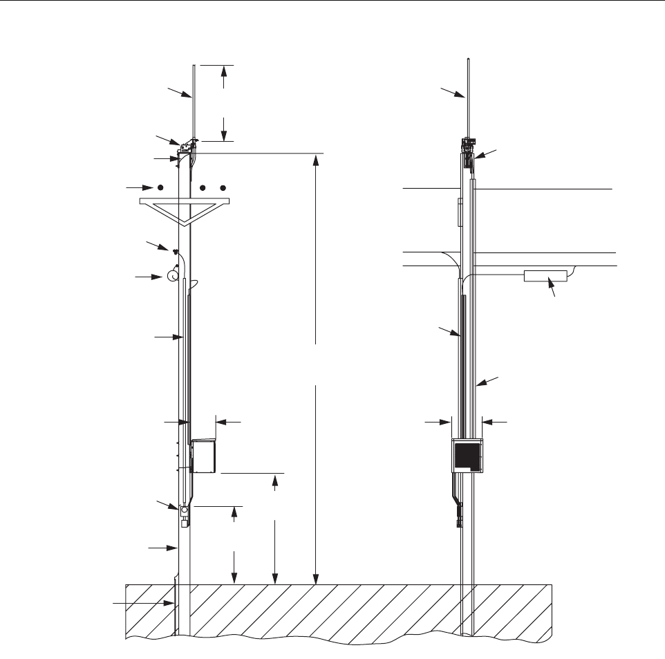
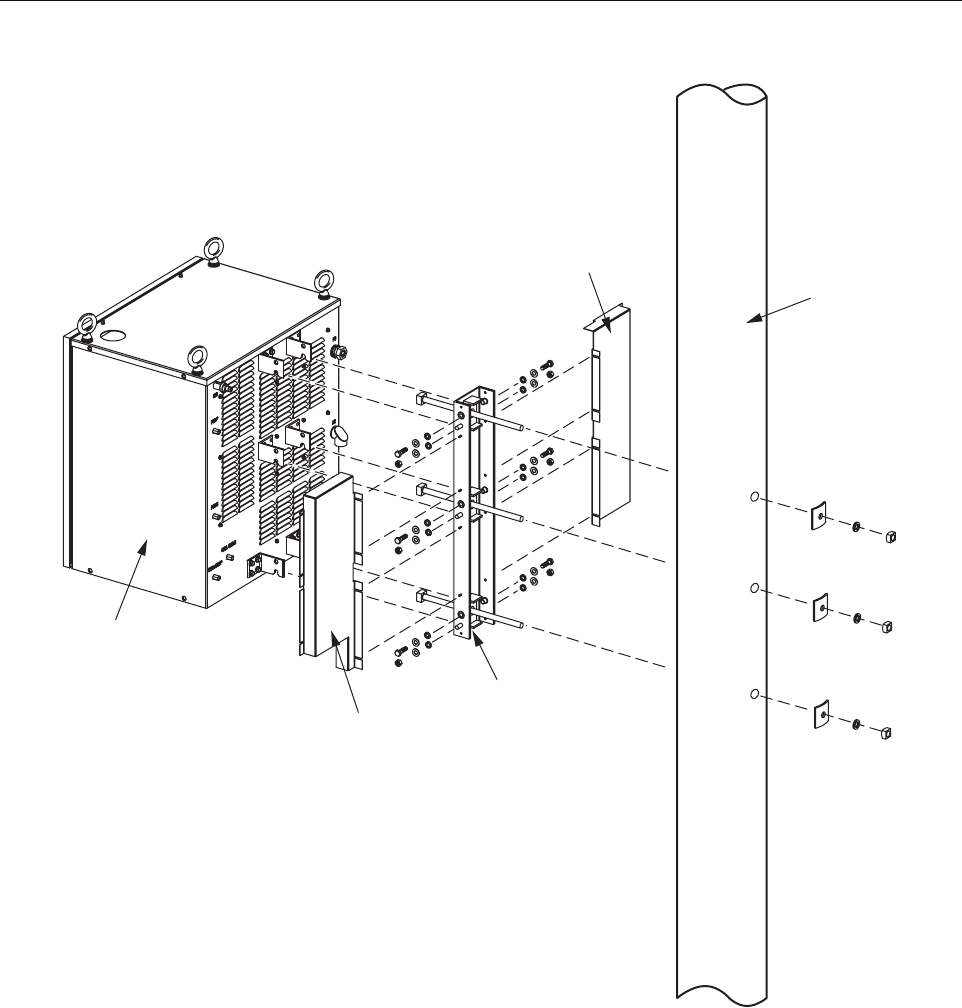
2.5 Installing a RAN Cabinet on a Wooden Utility Pole
Figure 24 shows the main components and their spatial placement in a typical NXD RAN pole
mount installation.
2.5.1 Site Requirements Unique to Pole Mounting Locations
If power lines are present at the top of the pole, spacing requirements applicable to the RF
cabling and any other hardware installed in the electric space must be considered. Per the
National Electrical Safety Code, vertical clearance at supports for primary-supply conductors
above other facilities is required to be 16 in. (40.64 cm) above neutrals and 40 in. (101.6 cm)
above communications (60 in. [152.4 cm] if above 8700V).
For supply conductors at voltages up to 8700 between conductors, the minimum horizontal
clearance provided by the NESC ANSI C2 is 12 in. (30.5 cm). For higher voltages, it is required
that .4 in. (10.2 mm) be added for every 1000V above 8700. Table 18 lists the required
clearances for some common high voltages.
This information is from the Standard Handbook for Electrical Engineers, 13th Edition,
McGraw Hill, Chapter 18, Section 151, Pages 18-65.
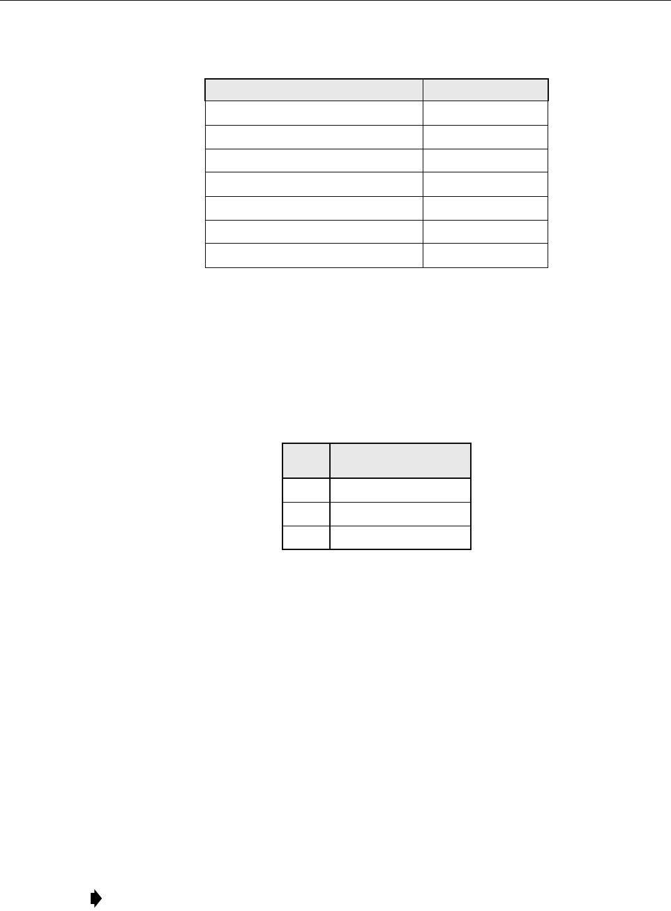
Table 18. Antenna Clearance vs. Voltage
VOLTAGE HORIZONTAL CLEARANCE
8700V 12.0 in. (30.5 cm)
15 kV 14.52 in. (36.9 cm)
28 kV 19.72 in. (50.1 cm)
38 kV 23.72 in. (60.2 cm)
ADCP-75-210 • Issue 1 • November 2006
Page 35
© 2006, ADC Telecommunications, Inc.
Figure 24. Typical Pole-Mount Installation
2.5.2 Pole Loading Analysis
A pole loading analysis should be performed before the RAN is mounted on the pole to verify
that the pole can support the weight of the RAN in various conditions. The analysis should take
into account the pole top antenna, the RAN and batteries, and the possibility of an expansion
RAN with batteries. Table 19 lists the weights of various NXD components and configurations.
21285-A
ANTENNA ANTENNA
ANTENNA
MOUNTING
BRACKET
100 IN.
(254 CM)
GROUND WIRE
TO ANTENNA
PRIMARY
POWER
PRIMARY POWER
SECONDARY POWER LINE
SECONDARY
POWER
FIBER
FIBER SPLICE CAN
FIBER OPTIC LINE
2 IN. SCHEDULE 40
CONDUIT FOR POWER IN
CARLTON PT. NO.
49011-010 OR
EQUIVALENT
SIDE
VIEW
FRONT
VIEW
27.5 IN.
(69.85 CM)
31.25 IN.
(79.4 CM)
7 FT. (2.1 M)
TYPICAL
JUNCTION
BOX
#6 AWG COPPER
GROUND WIRE TO
METER BOX, RAN,
AND ANTENNA
10 FT. (3 M)
TYPICAL
38.6 FT.
(11.8 M)
TYPICAL
1.5 IN. SCHEDULE 40
POLE RISER FOR
FIBER OPTIC LINES
CARLTON PT. NO.
59010N OR
EQUIVALENT
3 IN. SCHEDULE 40
CONDUIT FOR
RF CABLES
CARLTON PT. NO.
49013-010 OR
EQUIVALENT
RF CABLES
TO RAN
(5 REQUIRED)
COPPER
GROUND
ROD
ADCP-75-210 • Issue 1 • November 2006
Page 36
© 2006, ADC Telecommunications, Inc.
Three load types should be considered: static weight loading, ice loading, and wind loading.
These types should be considered on the pole, wires, and any equipment installed on the pole.
A qualified engineer should perform the pole loading analysis, taking into account both vertical
and horizontal forces. The specified horizontal load is applied 2 ft. (60.1 cm) from the top and
the assumption is that the pole acts as a cantilever with maximum stresses applied at the ground
level. Table 20 provides acceptable loads by pole class.
The strength of the wood pole is defined in Standard Handbook for Electrical Engineers, 13th
Edition, McGraw Hill, Chapter 18, Section 135, “Strength of Wood Poles,” Pages 18-57. The
wood pole strength calculation is defined in Standard Handbook for Electrical Engineers, 13th
Edition, McGraw Hill, Chapter 18, Section 136, Reference NEC.
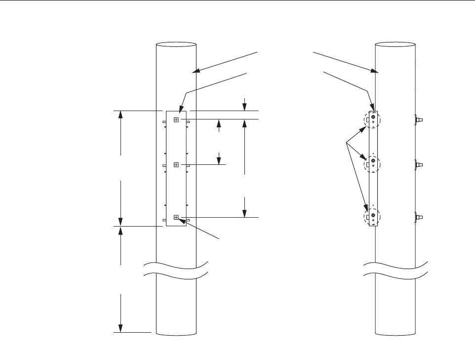
2.5.3 Installing the Cabinet Mounting Bracket
The Digivance NXD Wood Pole Mounting Bracket, shown in Figure 25, is an accessory item
that is used to attach the Digivance NXD cabinet to a power distribution pole or related object.
The bracket is attached to the pole using galvanized steel square head bolts that are attached
through holes drilled through the wooden pole. An example of an installed NXD wood pole
mounting bracket is shown in Figure 25.
Use the following procedure to install the RAN wood pole mounting bracket:
1. Determine the mounting height of the RAN and mark the pole at the desired location of
the base of the RAN.
Table 19. RAN Component Weights
CONFIGURATION OR COMPONENT WEIGHT
Base RAN without batteries 379 lbs. (172.3 kg)
Base RAN with four batteries 679 lbs. (308.6 kg)
Expansion RAN with four batteries 619 lbs. (281.4 kg)
Antenna pole-mount bracket (9 inch) 56 lbs. (25.5 kg)
Antenna pole-mount bracket (2 inch) 57 lbs. (25.9 kg)
Pole-top antenna (9 inch) 47 lbs. (21.4 kg)
Pole-top antenna (2 inch) 12 lbs. (5.5 kg)
Table 20. Loading by Pole Class
POLE
CLASS HORIZONTAL LOAD
1 5400 lbs. (2454.5 kg)
2 3700 lbs. (1681.8 kg)
3 3000 lbs. (1363.6 kg)
Note: Install the RAN pole mount bracket on the side of the utility pole assigned by the
utility company or required by local zoning.
ADCP-75-210 • Issue 1 • November 2006
Page 37
© 2006, ADC Telecommunications, Inc.
Figure 25. Cabinet Mounting Bracket
2. Place the pole mount bracket against the pole.
3. Strap or otherwise hold the bracket in place.
4. Using a level, adjust the bracket to make it vertically level.
5. Mark the three holes to be drilled through the wood pole.
6. Remove the pole mount bracket.
7. Drill three holes through the pole using a 7/8 in. wood bit.
8. Using a 3/4 in. machine bolt, put a 2 in. flat washer on the bolt.
9. Place the pole mounting bracket against the pole.
10. Align the holes in the bracket with the holes drilled in the pole.
11. Install one bolt through the bracket and pole (using any of the three holes).
12. Place a 3 in. square curved washer, lock washer, and 3/4 in. nut on the other end of the
machine bolt; do not tighten.
13. Repeat steps 8-12 for the other two holes.
14. Using a 1-1/8 in. wrench, tighten the mounting hardware to 103 ft.-lbs.
21286-A
UTILITY POLE
MOUNTING BRACKET
34.5 IN.
(87.6 CM)
13.5 IN.
(34.3 CM)
29.25 IN.
(74.3 CM)
2.63 IN.
(6.7 CM)
10 FT.
(3 M)
TYPICAL
RAN
ATTAC HME NT
POINTS
HOT DIPPED GALVANIZED MACHINE
BOLT SQUARE HEAD 3/4 x 16.00 LG
W/NUT (J9816) 3 REQUIRED
ROUND FLAT WASHER 2.00 O.D.
(J1089) 3 REQUIRED
SQUARE CURVED WASHER
3 x 3 x 1/4 (J6823) 3 REQUIRED
SPRING LOCK WASHER
.234 x.188 (J140) 3 REQUIRED
OR EQUIVALENT

ADCP-75-210 • Issue 1 • November 2006
Page 38
© 2006, ADC Telecommunications, Inc.
2.5.4 Mounting the RAN Cabinet on the Bracket
The cabinet is shipped with the mounting hardware required for mounting the RAN cabinet on
the RAN wood pole mounting bracket. The hardware consists of six 1/2 in. bolts, six nuts, 12
lock washers, and 12 flat washers. Use the following procedure to mount the cabinet. Refer to
Figure 26.
1. Remove the RAN from the mounting pallet.
2. Securely attach the boom truck cable to the four hoist eyes of the RAN.
3. Carefully raise the RAN toward the cabinet mounting bracket.
4. With a person in the bucket truck and positioned at the RAN pole mounting bracket, guide
the RAN onto the RAN pole mounting bracket so that the RAN holds onto the studs on the
mounting bracket.
5. Place a lock washer and a flat washer on a 1/2 in. by 1-3/4 in. bolt.
6. Screw the bolt in hand tight.
7. Repeat the previous two steps for the remaining five mounting holes.
8. Install a flat washer, lock washer, and nut on each of the six studs.
9. Using a 3/4 in. wrench, tighten the bolts to 75 ft.-lbs.
10. Carefully detach the boom truck cable from the hoist eye of the RAN.
11. Remove the hoist eyes by unscrewing from the RAN top.
2.5.5 Installing the Rain Shields
There are two rain shields to be installed on the rear of the RAN. They are identified as “rain
shield right” and “rain shield left.” Use the following procedure to install the rain shields. Refer
to Figure 26.
1. Using the supplied hardware, place the left rain shield over the three studs in the pole
mount bracket and three studs on the RAN.
2. Place a lock washer then a nut on each stud.
3. Using a nut driver or wrench, tighten to 6 ft.-lbs.
Caution: Do not install batteries in the RAN prior to mounting the RAN securely on the utility
pole.
Note: Once the RAN is hung on the studs, the through bolts will self-align.
ADCP-75-210 • Issue 1 • November 2006
Page 39
© 2006, ADC Telecommunications, Inc.
Figure 26. Pole Mount Components
2.6 Installing a RAN Cabinet on a Concrete Pad
This section contains the procedures for installing the RAN on a concrete pad.
Choose an installation site that conforms to all local codes. Obtain all required permits prior to
starting installation. Situate the concrete pad along the trench that was used for routing the OSP
fiber cables for the system.
RAN
CABINET
POLE MOUNT
BRACKET
RAIN
SHIELD
LEFT
RAIN
SHIELD
RIGHT
UTILITY
POLE
21345-A
ADCP-75-210 • Issue 1 • November 2006
Page 40
© 2006, ADC Telecommunications, Inc.
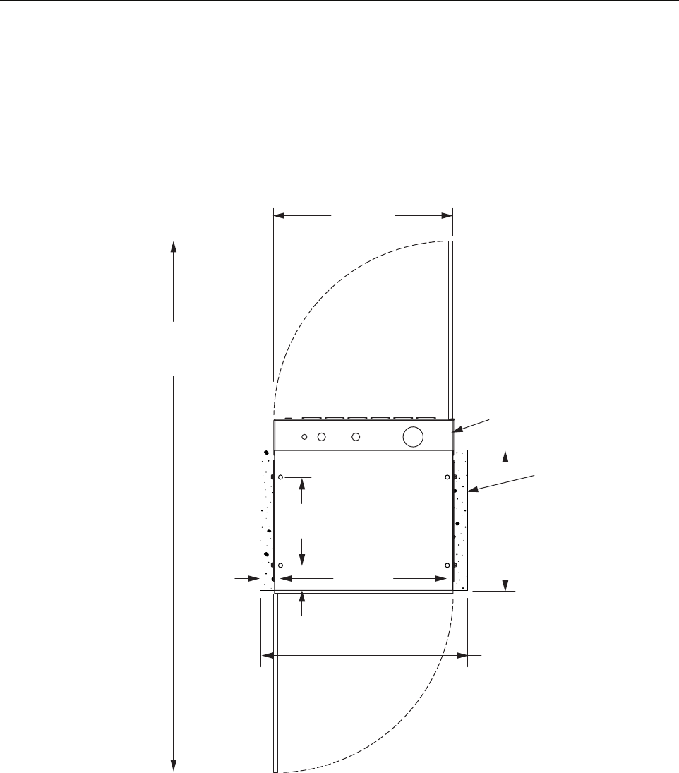
2.6.1 Pouring a Concrete Pad
Prepare a base for the concrete pad that meets all local code requirements. The base must have a
footing of 4 to 6 inches (10.2 to 15.2 cm) of sand or gravel on firmly compacted soil. Concrete
pad height is site and climate dependent. Height should be based on keeping the front door air
intake louvers and rear bottom exhaust vent free of obstruction. For dimensions of pad, refer to
Figure 27.
Figure 27. Concrete Pad Dimensions
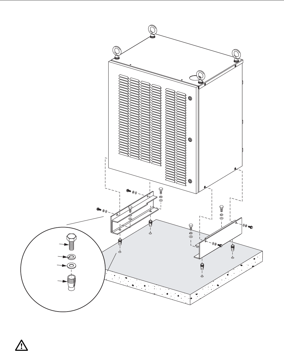
2.6.2 Mounting the Cabinet on a Concrete Pad
Use the following procedure to mount the cabinet on the concrete pad.
1. Fasten the pedestal mounts to the concrete pad using the customer-supplied hardware
identified in Figure 28.
15.38 IN.
(39.07 CM)
4.3 IN.
(10.9 CM)
29.00 IN.
(73.66 CM)
HOLES FOR
PEDESTAL
MOUNT
24.0 IN.
(61 CM)
3.5 IN.
(8.9 CM)
36.0 IN.
(91 CM)
31.0 IN.
(79 CM)
CONCRETE PAD
(MINIMUM SIZE)
RAN CABINET/
PEDESTAL ENCLOSURE
FOOT PRINT
DOOR
CLEARANCE
92.0 IN.
(234 CM)
21308-A
ADCP-75-210 • Issue 1 • November 2006
Page 41
© 2006, ADC Telecommunications, Inc.
Figure 28. Installing Pedestal Mount and Cabinet
2. Using appropriate lifting equipment, lower the cabinet into position on the cabinet mounts.
3. Secure the cabinet from the side, as shown, using the four bolts, four flat washers, and four
lock washers from the shipping pallet mounting brackets.
Warning: Use appropriate lifting equipment when moving or installing the cabinet. Do not
stand under the cabinet as it is being hoisted into position for installation. A failure of the lifting
equipment could result in serious personal injury.
21306-A
1/2 x 13
BOLT
CONCRETE
ANCHOR
LOCK
WASHER
FLAT
WASHER
TYPICAL CUSTOMER
SUPPLIED HARDWARE
(4 PLACES)
ADCP-75-210 • Issue 1 • November 2006
Page 42
© 2006, ADC Telecommunications, Inc.
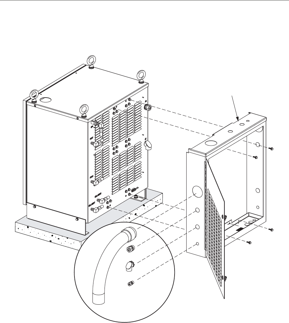
2.6.3 Installing the Pedestal Enclosure
The pedestal enclosure, shown in Figure 29, mounts on the back of the cabinet.
Figure 29. Installing Pedestal Enclosure
Use the following procedure to install the pedestal enclosure:
1. Orient the pedestal enclosure as shown and attach it to the back of the cabinet using the
four bolts provided.
2. Close the pedestal enclosure door and secure the door with the key provided.
CUSTOMER SUPPLIED
OPTIONAL FITTINGS
PEDESTAL
ENCLOSURE
21309-A
ADCP-75-210 • Issue 1 • November 2006
Page 43
© 2006, ADC Telecommunications, Inc.
2.7 Other Standard Installation Procedures
This section contains other procedures done at every installation after the RAN is mounted on a
wooden pole or concrete pad.
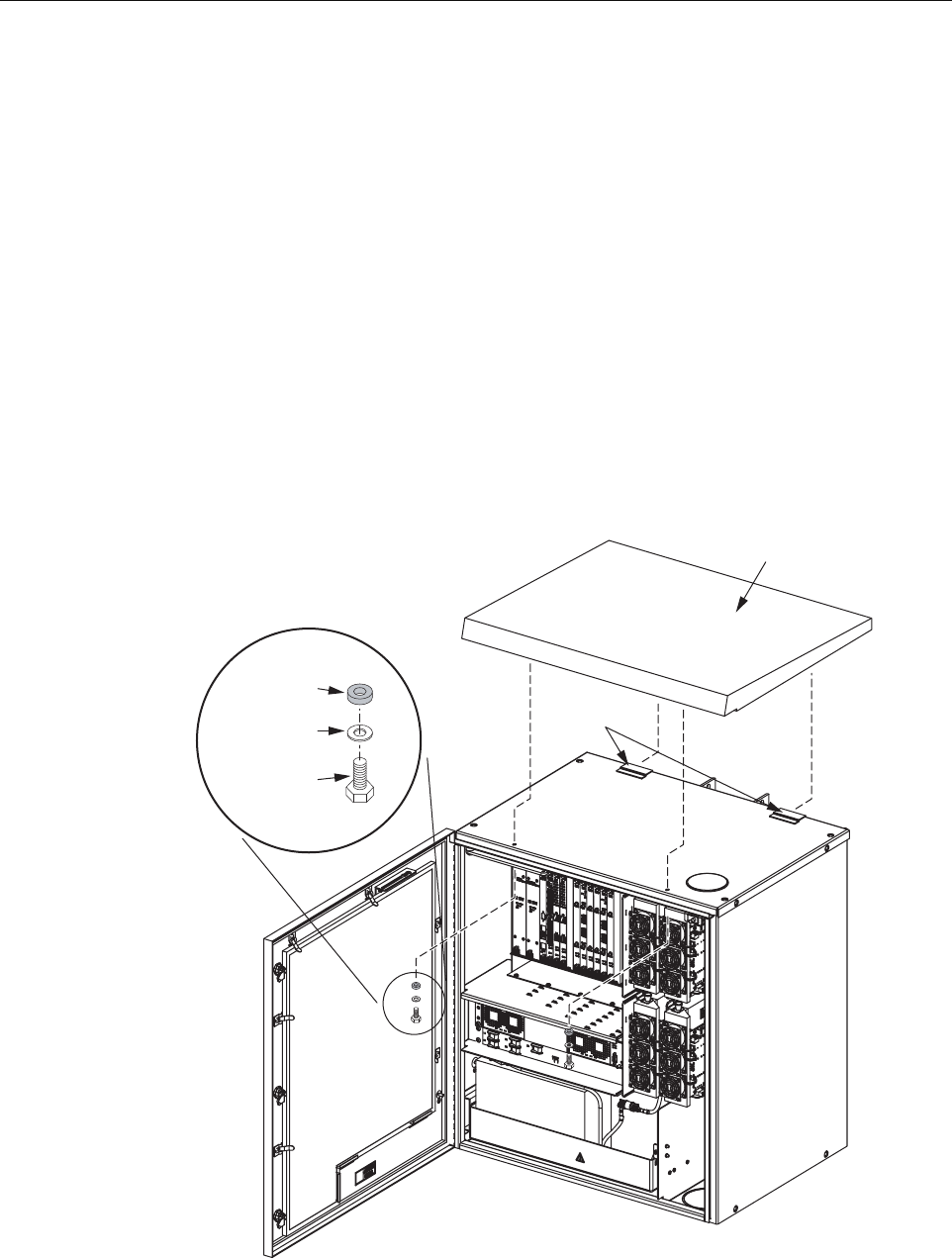
2.7.1 Installing a Solar Shield
Each RAN has a solar shield that mounts on top of the cabinet. Hardware for the solar shield can
be found in a bag fastened to the inside of the battery compartment. The hardware consists of
two 1/4 in. bolts, each with flat washer and sealing washer. Use the following procedure to
install the solar shield. Refer to Figure 30.
1. Remove the solar shield from its packaging.
2. Place a lock washer and flat washer and then the sealing washer on each 1/4 in. machine
bolt.
3. Using the key provided, open the RAN door.
Figure 30. Installing the Solar Shield
TANGS
RUBBER
SEALING
WASHER
FLAT
WASHER
1/4 x 20
HEX HEAD
BOLT
EACH SIDE
SOLAR
SHIELD
21339-A

ADCP-75-210 • Issue 1 • November 2006
Page 44
© 2006, ADC Telecommunications, Inc.
4. Locate the two 1/4 in. machine bolts, each with flat washer and sealing washer, in a bag
fastened to the inside of the battery compartment.
5. Place the solar shield on the top of the RAN.
6. Push the solar shield backward until it extends slightly beyond the back of the cabinet then
pull it forward catching the two tangs of the solar shield on the top of the RAN.
7. Locate the two clearance holes on the left and right sides just inside the door frame.
8. Align the solar shield threaded holes with the clearance holes and insert the two 1/4 in.
machine bolts in the hole.
9. Using a 7/16 in. nut driver or socket screw, tighten the two 1/4 in. machine bolts to secure
the solar shield. Tighten to 6 ft.-lbs.
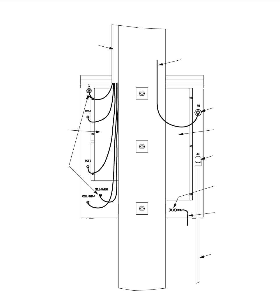
2.7.2 Installing a Ground Wire
Each RAN is designed with provisions for connecting to earth ground. Earth grounding is to be
done in accordance with the National Electric Code and local building code. Two ground studs
for connecting the ground wire are located on the back of the RAN (Figure 31). A 2-hole
compression type lug terminal should be installed on the ground studs for connecting a #6 AWG
copper grounding wire.
The following material must be supplied by the installer:
• Panduit LLCF6-14B-L or equivalent (X2)
• Two-hole compression lug terminal for #6 AWG wire
• #6 AWG wire
• Connector for attaching the wire to an approved ground source
The following tools are required to perform this procedure:
• Compression pliers for #6 AWG grounding lug
• Wire cutters
• Wire stripper
Use the following procedure to install the ground wire:
1. Obtain a length of #6 AWG (4 mm) copper wire for use as a cabinet grounding wire.
2. Crimp the #6 AWG copper grounding wire to the compression lug.
3. Secure the compression lug to the back of the cabinet.
4. Route the free end of the grounding wire to an approved earth ground source.
5. Cut the grounding wire to length and connect it to the earth ground source as specified by
local code.
Caution: For proper equipment operation, an approved earth ground connection must be
provided. The recommended minimum wire size is #6 AWG copper wire.
ADCP-75-210 • Issue 1 • November 2006
Page 45
© 2006, ADC Telecommunications, Inc.
Figure 31. Cable Connection Points
2.7.3 Installing RF Cabling
RF cabling on the RAN connects the RF antenna to the RF input on the back of the RAN. There
are five Type N receptacles on the antenna and five Type N receptacles on the back of the RAN,
identified in Table 21 on page 47.
There are two main steps in installing RF cables: weatherproofing the cables, and routing and
securing the cables.
21287-A
RF LINE CONDUIT
(FROM ANTENNA)
TYPE N CONNECTORS
FOR ANTENNA AND
GPS CONNECTORS
LEFT
RAIN
SHIELD
FIBER OPTIC
CONDUIT
FIBER OPTIC
ENTRANCE
RIGHT
RAIN
SHIELD
POWER ENTRANCE
220 VAC PRIME POWER
220 VAC RIGID
CONDUIT
GROUND
WIRE
GROUND
LUG

ADCP-75-210 • Issue 1 • November 2006
Page 46
© 2006, ADC Telecommunications, Inc.
2.7.3.1 Weatherproofing RF Cables
RF cables should be weatherproofed before being installed. The following materials are
required (customer supplied):
• 3M 8426-9M cold shrink
• 3M Skothkote Electrical Coating 14853
Use the following procedure to weatherproof the RF cables:
1. Prior to connecting the RF cables to either the RAN or antenna, place one 3M 8426-9M
cold shrink kit over the cable end, then connect the cable end to its intended termination
point. Follow the manufacturer’s directions, which are included with each kit.
2. After the cold shrink has been applied, coat the entire length of the cold shrink material
with the 3M Scotchkote Electrical Coating, number 14853.
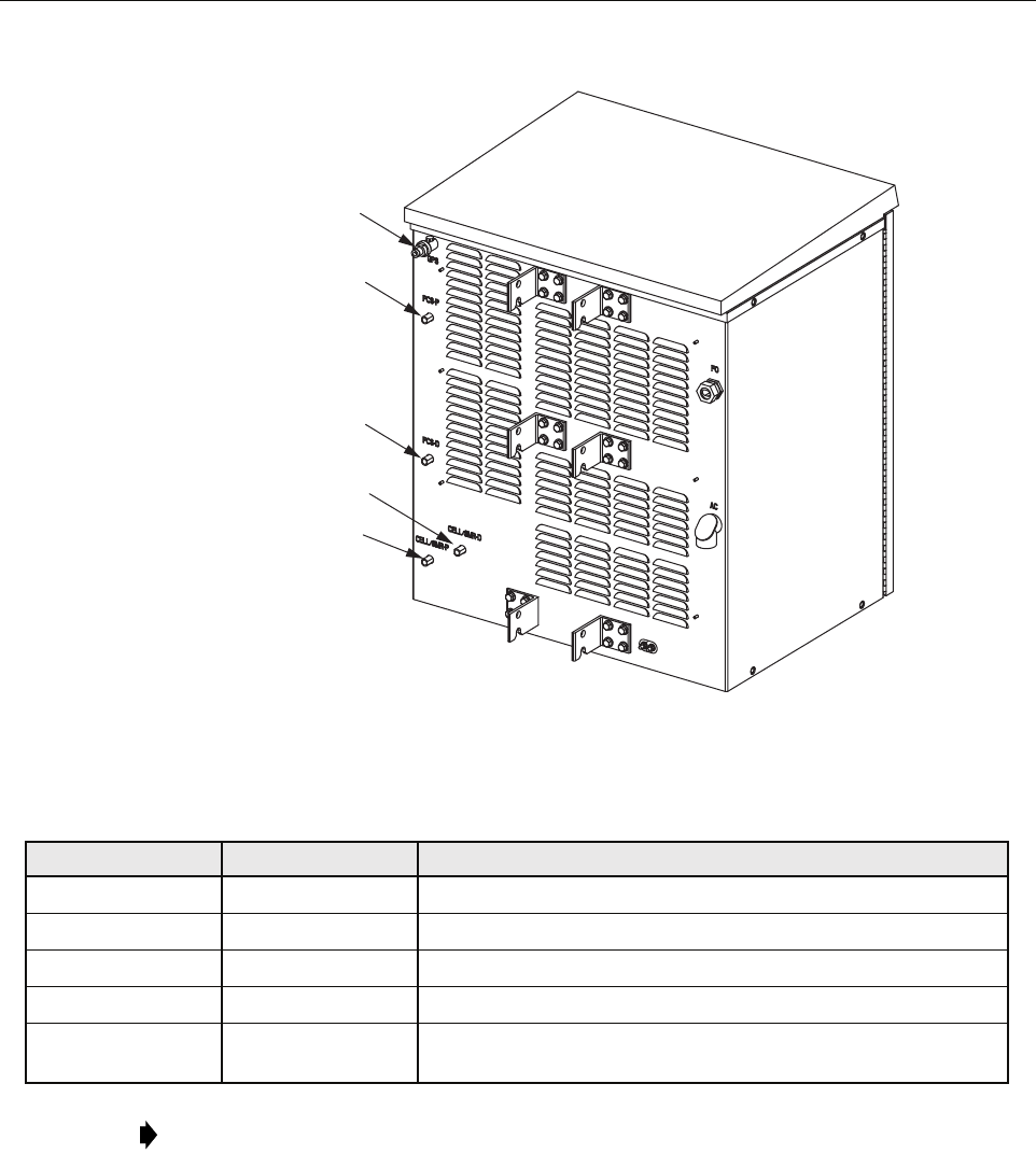
2.7.3.2 Routing and Securing RF Cables
For cable installation, the following materials are required (customer supplied):
• 10 Type N male plugs (CommScope PN: 540ANM or equivalent)
• Coax cable (CommScope PN: FXL540OPE or equivalent)
• Electrician’s tape
• Water seal
Use the following procedure to route and secure the RF cabling:
1. Measure from the antenna base connectors to the RAN connectors to determine the coax
cable length including service loops and drip loops. Refer to Figure 24 on Page 35.
2. Install the Type N plugs on each end of each of the RF cables.
3. Attach each end of the cables to the appropriate connectors on the antenna base and the
RAN. Refer to Figure 32 and Table 21.
4. Tighten each connector to 20 ft.-lbs.
5. After each connector is tightened, cover the entire connection with electrician’s tape, then
wrap the connection in water seal and finally cover the water seal with wraps of
electrician’s tape.
Note: Read and understand the manufacturer’s instructions prior to using these products.
Note: Right angle connectors may not be needed if there is enough space or if the coax
cable is flexible enough to create a proper bend radius in the cable. Reference the coax
cable manufacturer specifications for allowable bend radii.
Note: A cable sweep test is highly recommended. When testing the RF and GPS coaxial
cables, use a matched load. The VSWR should be 1:1:1. The return loss should be 26.444
dB or better.
ADCP-75-210 • Issue 1 • November 2006
Page 47
© 2006, ADC Telecommunications, Inc.
Figure 32. Installing the RF Cables
2.7.4 Installing Pre-Connectorized Indoor/Outdoor Fiber Optic Cable
Fiber optic cable installation consists of routing a pre-connectorized outdoor-rated fiber optic
cable from an external splice enclosure to the NXD RAN cabinet, routing the cable into the
cabinet, and then breaking out the individual fibers for connection. The NXD RAN has a fiber
interface on the front of the Synchronous Interface (SIF) Module in the RAN chassis. The fiber
enters the cabinet on the rear side.
Table 21. RAN Antenna Ports and Antenna Base Ports
LABEL ON RAN LABEL ON ANTENNA BAND
GPS GPS Global Positioning System (GPS)
PCS-P PCS-T PCS primary receive path and transmits from PCS A, B or F
PCS-D PCS-B PCS diversity receive path and transmits from PCS D, E or C
CELL/SMR-D CELL/SMR-D Cell/SMR primary receive path and transmits from Cell A”/A
CELL/SMR-P CELL/SMR-P Cell/SMR diversity receive path and transmits from SMR A or
Cell B/B’
Note: When building out RANs, connect the quadplexers that will contain the first PCS
bands to the top of the PCS antenna element. On the Phasar antenna, this is marked on the
base PCS-T.
21278-A
GPS
PCS-P
PCS-D
CELL/SMR-P
CELL/SMR-D
ADCP-75-210 • Issue 1 • November 2006
Page 48
© 2006, ADC Telecommunications, Inc.
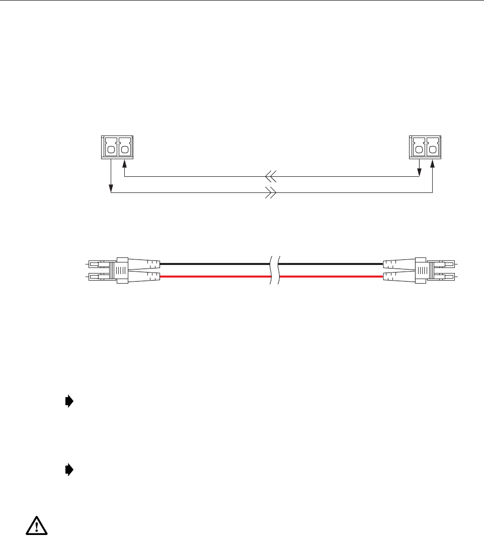
All fiber optic cable connections require single-mode Dual-LC type connectors.
Figure 33 shows the basic configuration of the optical path between the Hub SIF and the RAN
SIF. For optical specifications, refer to Table 2 on page 6.
Figure 33. Optical Path Between Hub SIF and RAN SIF
For fiber cable ingress, the RAN is equipped with a nylon fiber optic connector located on the
rear side of the cabinet. The connector accommodates cables of a diameter in the range .38 to
.50 inches (.97 to 1.27 cm).
Use the following procedure to install the fiber optic cable:
1. Route the connectorized end of the fiber optic cable from the splice enclosure (not
provided) to the rear side of the cabinet. Estimated length of cable is 30 feet (9 meters)
although this is dependent upon distance from the splice enclosure.
Note: If the installer has a larger cable, the manufacturer (Hubbell Inc.) makes bushings
that fit this connector in the following size ranges: .500-.625, .625-.750, .750-.875, .875-
1.00, 1.00-1.125 inches.
Note: The routing of an Outside Plant (OSP) fiber optic cable from the Hub to a splice
enclosure in the vicinity of the RAN cabinet and the splicing of selected OSP cable fibers
to the fibers in the outdoor-rated cable is the responsibility of the installer.
Warning: This equipment uses a Class 1 Laser according to FDA/CDRH rules. Laser radiation
can seriously damage the retina of the eye. Do not look into the ends of any optical fiber. Do not
look directly into the optical transmitter of any unit or exposure to laser radiation may result.
An optical power meter should be used to verify active fibers. A protective cap or hood MUST
be immediately placed over any radiating transmitter or optical fiber connector to avoid the
potential of dangerous amounts of radiation exposure. This practice also prevents dirt particles
from entering the connector.
FIBER PORT
TX RX
FIBER PORT
TX RX
REVERSE PATH
BASIC CONFIGURATION BETWEEN HUB SIF SFP AND RAN SIF SFP
END-TO-END OPTICAL CONNECTOR/CABLE ASSEMBLY DIAGRAM
FORWARD PATH
21353-A