ADC Telecommunications DNXSMR1A Digivance® NXD SMR 900 MHz System User Manual 75210
ADC Telecommunications Inc Digivance® NXD SMR 900 MHz System 75210
UserManual.wiki
>
ADC Telecommunications
>
DNXSMR1A User Manual
>
User Manual 2
Contents
1.
User Manual 1
2.
User Manual 2
3.
User Manual 3
4.
User Manual 4
User Manual 2
Navigation menu
Upload a User Manual
Namespaces
Wiki Guide
HTML
PDF
Info
Views
User Manual
Discussion / Help
Navigation
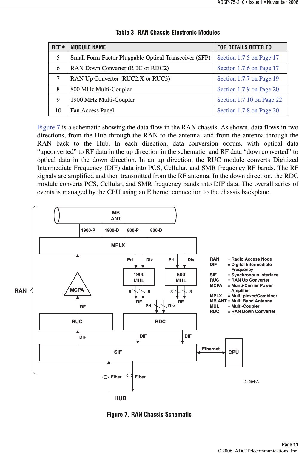
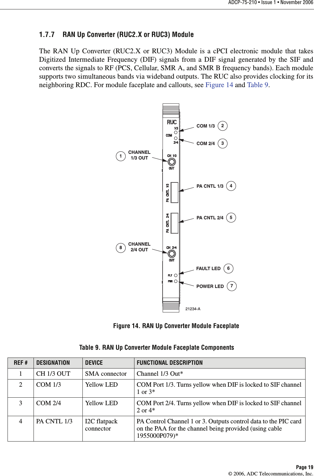
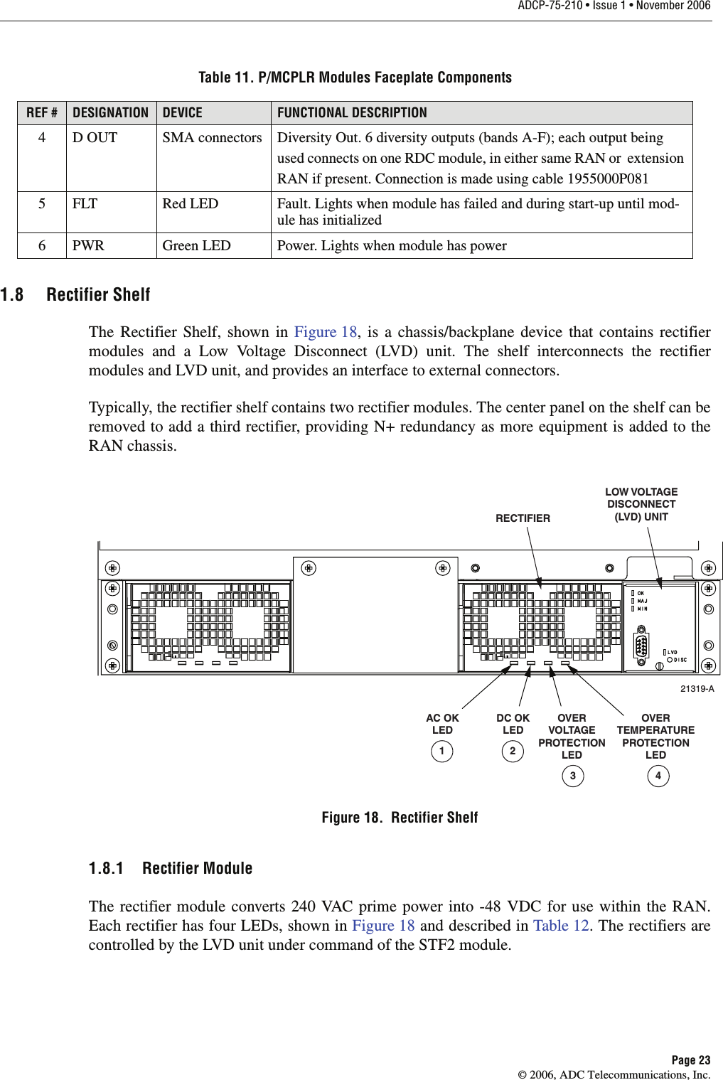
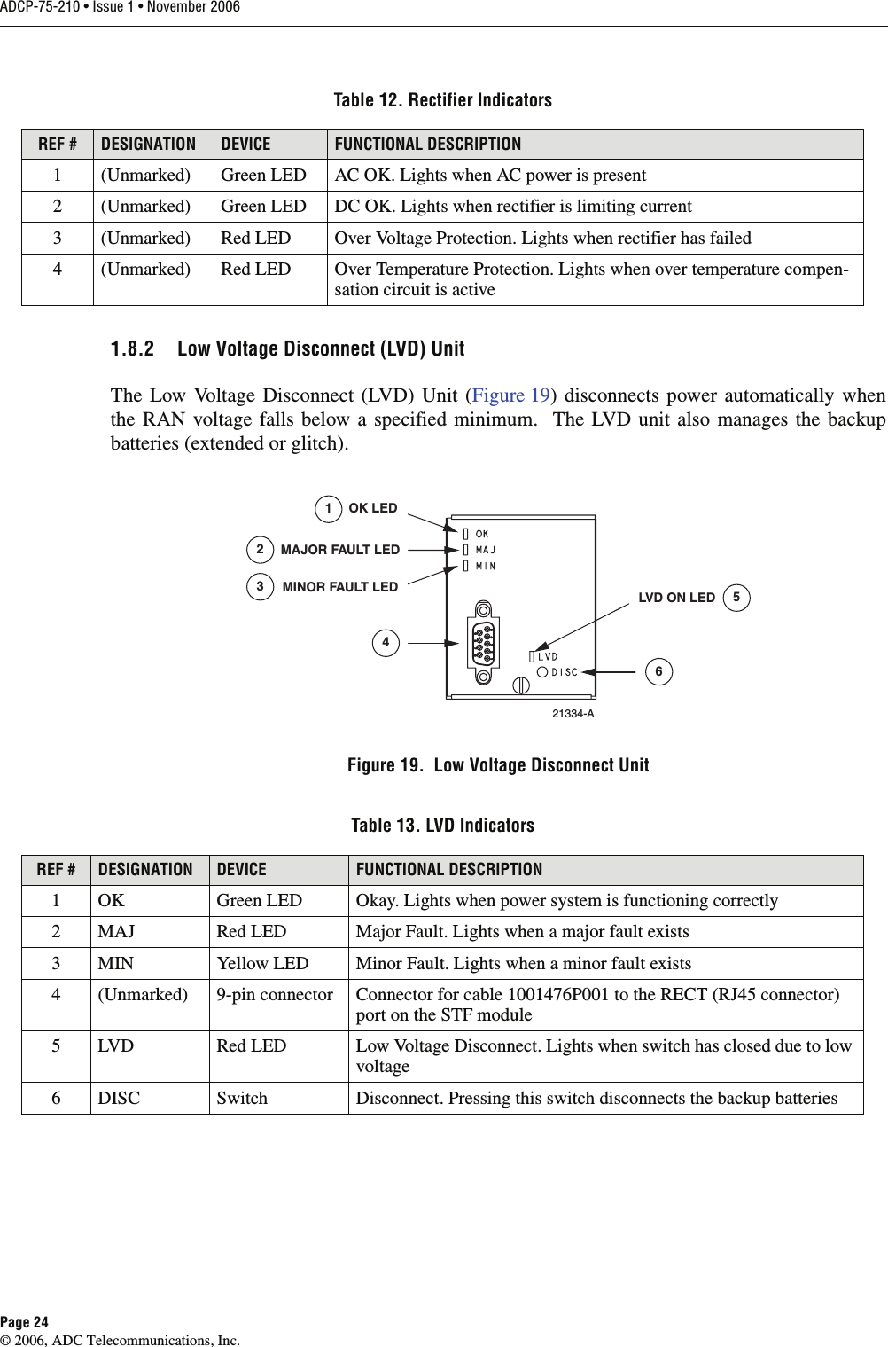
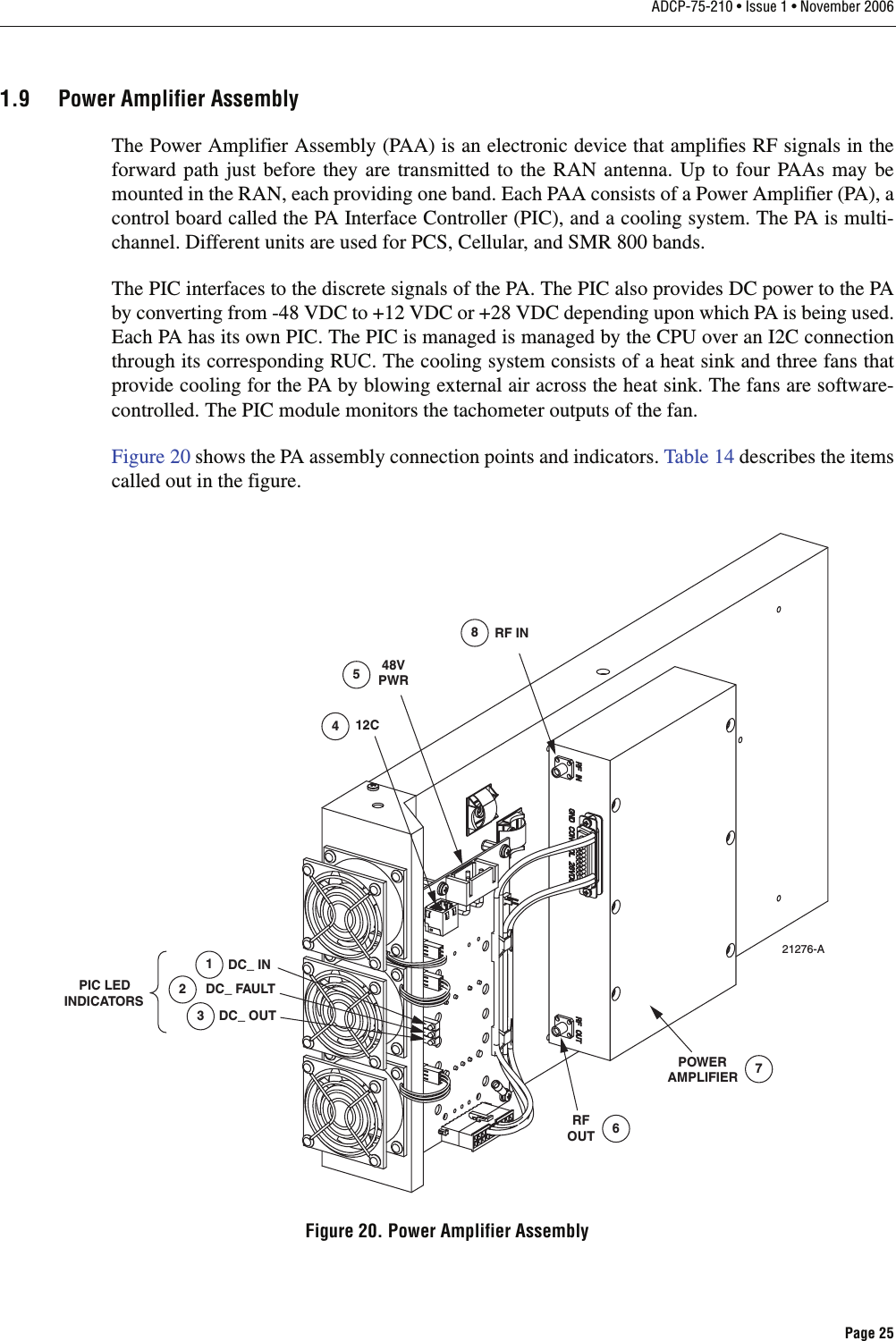
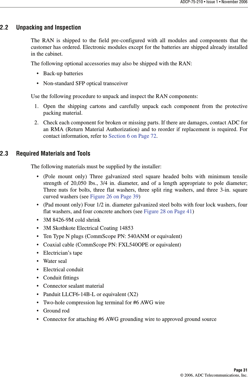
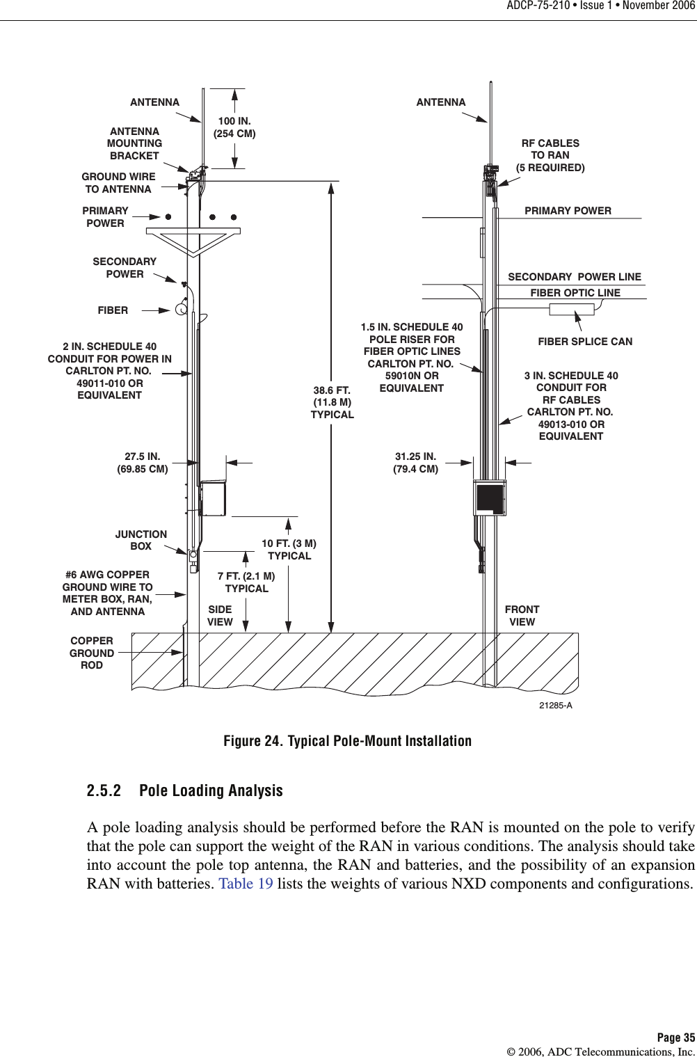
![ADCP-75-210 • Issue 1 • November 2006Page 34© 2006, ADC Telecommunications, Inc.2.5 Installing a RAN Cabinet on a Wooden Utility PoleFigure 24 shows the main components and their spatial placement in a typical NXD RAN polemount installation.2.5.1 Site Requirements Unique to Pole Mounting LocationsIf power lines are present at the top of the pole, spacing requirements applicable to the RFcabling and any other hardware installed in the electric space must be considered. Per theNational Electrical Safety Code, vertical clearance at supports for primary-supply conductorsabove other facilities is required to be 16 in. (40.64 cm) above neutrals and 40 in. (101.6 cm)above communications (60 in. [152.4 cm] if above 8700V).For supply conductors at voltages up to 8700 between conductors, the minimum horizontalclearance provided by the NESC ANSI C2 is 12 in. (30.5 cm). For higher voltages, it is requiredthat .4 in. (10.2 mm) be added for every 1000V above 8700. Table 18 lists the requiredclearances for some common high voltages.This information is from the Standard Handbook for Electrical Engineers, 13th Edition,McGraw Hill, Chapter 18, Section 151, Pages 18-65.Table 18. Antenna Clearance vs. VoltageVOLTAGE HORIZONTAL CLEARANCE8700V 12.0 in. (30.5 cm)15 kV 14.52 in. (36.9 cm)28 kV 19.72 in. (50.1 cm)38 kV 23.72 in. (60.2 cm)](https://usermanual.wiki/ADC-Telecommunications/DNXSMR1A.User-Manual-2/User-Guide-756623-Page-26.png)