ADC Telecommunications DNXSMR1A Digivance® NXD SMR 900 MHz System User Manual 75210
ADC Telecommunications Inc Digivance® NXD SMR 900 MHz System 75210
Contents
- 1. User Manual 1
- 2. User Manual 2
- 3. User Manual 3
- 4. User Manual 4
User Manual 4
ADCP-75-210 • Issue 1 • November 2006
Page 64
© 2006, ADC Telecommunications, Inc.
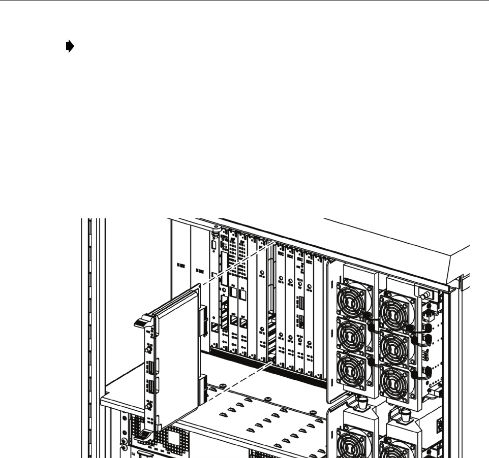
3. Slide the RDC module into the designated slot within the RAN chassis.
4. Lock the IEL handles on the top and bottom of the RDC module into the chassis and
tighten the handle screws.
5. Using an SMA coaxial cable (1955000P081), connect one end to the PRI IN port on the
RDC module and the other end to the appropriate P OUT port on the C/MCPLR or P/
MCPLR module. Each P OUT port is associated with a different band.
6. Using an SMA coaxial cable (1955000P081), connect one end to the DIV IN port on the
RDC module and the other end to the appropriate D OUT port on the C/MCPLR or P/
MCPLR module. Each D OUT port is associated with a different band. For more
information on these ports, refer to the sections identified in the note above.
21235-AX
Figure 44. Installing an RDC Module
4.1.6 Installing a RAN Up Converter (RUC2.X or RUC3) Module
The RAN Up Converter (RUC2.X or RUC3) module may be installed into either of two slots in
the RAN chassis, depending on the band for which the module will be used. One module is
required for each two bands. The two slots are:
• Slot 11 (labeled RUC A2): used for first and second bands
• Slot 14 (labeled RUC A5): used for third and fourth bands
Note: For more information on the C/MCPLR module ports, see Section 1.7.9, 800 MHz
Multicoupler (C/MCPLR), on page 20. For more information on the P/MCPLR module
ports, see Section 1.7.10, 1900 MHz Multicoupler (P/MCPLR), on page 22.
ADCP-75-210 • Issue 1 • November 2006
Page 65
© 2006, ADC Telecommunications, Inc.
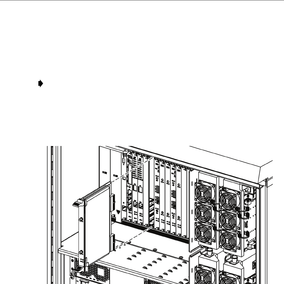
Use the following procedure to install an RUC2.X or RUC3 module (Figure 45):
1. Identify the designated chassis slot for the RUC module. This will be Slot 11 or 14. For
more information, see introductory text above.
2. Remove the RUC module from the anti-static packaging and orient for installation.
3. Slide the RUC module into the designated slot within the RAN cPCI chassis.
4. Lock the IEL handles on the top and bottom of the RUC module into the cPCI chassis and
tighten handle screws.
21233-AX
Figure 45. Installing an RUC Module
5. Using cable 1955000P079, connect the CH1/3 connector on the RUC module to either of
the following as appropriate:
– RF IN port on PAA1 if RUC module is in slot A2
– RF IN port on PAA3 if RUC module is in slot A5
6. Using cable 1955000P079, connect the CH 2/4 connector on the RUC module to either of
the following as appropriate:
– RF IN port on PAA2 if RUC module is in slot A2
– RF IN port on PAA4 if RUC module is in slot A5
Note: For a description of the module including function, controls, and indicators, refer to
Section 1.7.7 on Page 19. For a RAN chassis interconnection diagram, refer to Figure 39
on Page 58.

ADCP-75-210 • Issue 1 • November 2006
Page 66
© 2006, ADC Telecommunications, Inc.
7. Using cable 1001475P001, connect the PA CTL1/3 connector on the RUC module to
either of the following as appropriate:
– CNTL port on PAA1 if RUC module is in slot A2
– CNTL port on PAA3 if RUC module is in slot A5
8. Using cable 1001475P001, connect the CTL 2/4 connector on the RUC module to either of
the following as appropriate:
– CNTL port on PAA2 if RUC module is in slot A2
– CNTL port on PAA4 if RUC module is in slot A5
4.2 Installing cPCI Chassis Air Baffles
The air baffles for the RAN chassis are used in all empty chassis slots. This is done to maintain
airflow around the chassis modules.
Use the following procedure to install air baffles:
1. Identify designated RAN Chassis cPCI slot for the cPCI air baffle.
2. Insert air baffle into designated slot on chassis and tighten screws.
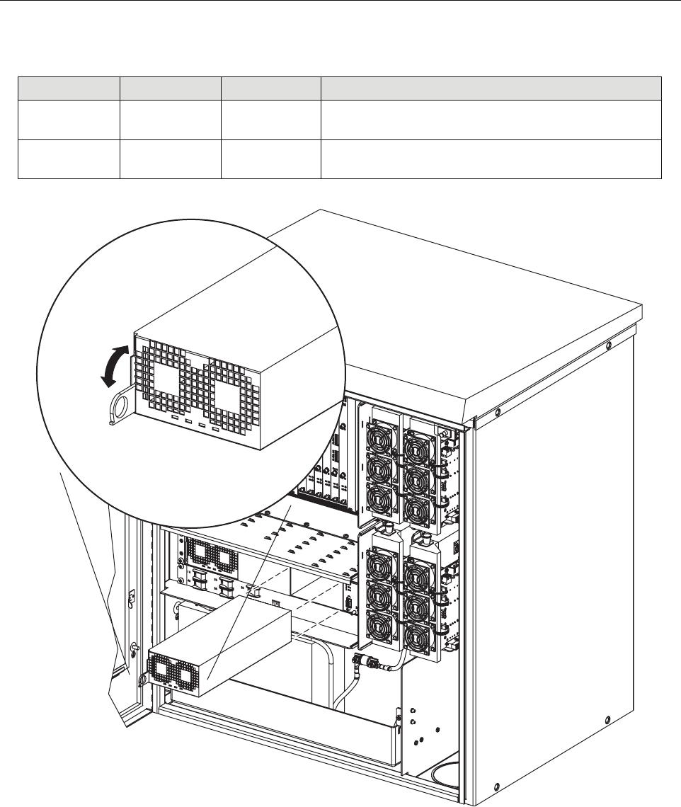
4.3 Installing a Rectifier Module
To install a rectifier module, use the following procedure (Figure 46):
1. Connect cables following Section 22 on Page 66.
2. Slide the rectifier into the rectifier compartment.
3. Turn the gravity latch down to lock the rectifier in place.
Note: For a description of the rectifier including function, controls, and indicators, refer
to Section 1.8 on Page 23. For a RAN chassis interconnection diagram, refer to Figure 39
on Page 58.
Table 22. Rectifier Ports and Connections
RECTIFIER PORT CONNECTS TO USING CABLE COMMENTS
L1, L2, L3 EMI Line Filter
F-L1, F-L2
1001473P001 Connect black wire to F-L1 (on EMI Line Filter); connect
brown wire to FL-2
RECT GND GND Stud 1001473P001 Connect to cabinet ground stud
+BAT, - BAT Anderson con-
nector
1001477P001 Connect to Anderson connector in battery compartment;
connect black wire to 0V (+BAT) and blue wire to -BAT
OV OUT,
-OV OUT
temp sensor,
circuit break-
ers REC+ and
REC-
1001477P001
1001469P001
1001470P001
Place temperature sensor in battery compartment; connect
1001477P001 black wire to OV OUT and blue wire to -
OV OUT; connect 1001469P001 from rectifier OV OUT
to circuit breaker POS; connect 1001470P001 from recti-
fier -OV OUT to circuit breaker NEG
ADCP-75-210 • Issue 1 • November 2006
Page 67
© 2006, ADC Telecommunications, Inc.
Figure 46. Installing a Rectifier
25 Pin D Circuit breaker
panel N/C port
1001477P001 Connect white wire to circuit breaker N/C and brown wire
to COM
RS232 STF module
RECT port
1001476P001 Connect to STF module connector labeled RECT in RAN
chassis and RS-232 connector on the rectifier
Table 22. Rectifier Ports and Connections
RECTIFIER PORT CONNECTS TO USING CABLE COMMENTS
21274-A
LOCK
UNLOCK

ADCP-75-210 • Issue 1 • November 2006
Page 68
© 2006, ADC Telecommunications, Inc.
4.4 Installing a Compact PCI Power Supply (cPCI P/S) Module
The cPCI Power Supply Module installs into Slots 1 and 2 or Slots 3 and 4 of the RAN chassis.
One module is required per RAN chassis. Either set of two slot can be used. A second module
can be installed for redundancy.
Use the following procedure to install a cPCI Power Supply Module:
1. Identify the designated chassis slots for the module. This will be Slots 1 or 2 or Slot 3 and
4.
2. Remove the module from the anti-static packaging and orient for installation.
3. Slide the module into the designated slots within the RAN cPCI chassis.
4. Lock the IEL handles on the top and bottom of the RUC module into the cPCI chassis and
tighten handle screws.
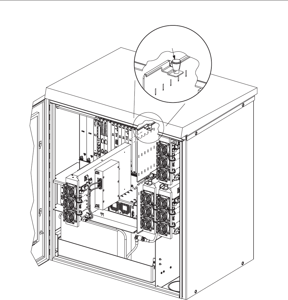
4.5 Installing a Power Amplifier Assembly
The RAN holds up to four PAAs. One PAA is required for each band being supported. Use the
following procedure to install a PAA:
1. Connect cables per Table 23.
2. Slide the PAA into place.
Note: For a description of the cPCI P/S module including function, controls, and
indicators, refer to Section 1.7.1 on Page 12. For a RAN chassis interconnection diagram,
refer to Figure 39 on Page 58.
Note: For a description of the PAA including function, controls, and indicators, refer to
Section 1.9 on Page 25. For a RAN chassis interconnection diagram, refer to Figure 39 on
Page 58.
Table 23. PAA Connections
PAA PORT CONNECTS TO USING CABLE TYPE COMMENTS
I2C (J2) RUC module P/A
CNTL 2/4 or 1/3
1001475P001 RJ-45 connector. Connect cable from
PIC module port J2 (CNTL) to RUC
P/A CNTL 1/3 or P/A CNTL 2/4
48V PWR (J1) Circuit breaker
1A, 2A, 3A, or
4A port
1001471P001 Positronic 3-pin connector. Connect
cable from PIC module J1 port to cir-
cuit breaker 1A, 2A, 3A, or 4A port;
the circuit breaker has an individual
output for each of the four PAAs
RF OUT Plexer module
TX port
1955000P080 SMA connector. Connect cable from
PAA RF OUT to plexer port TX
RF IN RUC module CH
1/3 or CH 2/4
port
1955000P079 SMA connector. Connect cable from
PAA RF IN port to RUC module
CH 1/3 or CH 2/4 port
ADCP-75-210 • Issue 1 • November 2006
Page 69
© 2006, ADC Telecommunications, Inc.
Figure 47. Installing a PAA
21246-A
RAISE KNOB TO
UNLATCH RECTIFIER

ADCP-75-210 • Issue 1 • November 2006
Page 70
© 2006, ADC Telecommunications, Inc.
5 MAINTENANCE PROCEDURES
This section provides procedures for completing various maintenance tasks at the RAN. Refer
to the procedures in this section as necessary when scheduled maintenance is required. For fault
and troubleshooting procedures, refer to the system operation and maintenance manual, ADCP-
75-209.
5.1 cPCI Fan Replacement Procedure
The RAN chassis is equipped with a cooling fan that exhausts heated air from the chassis
assembly. Cool air enters the cPCI chassis through vent openings on the front door of the
cabinet. The recommended replacement interval is 60 months.
Use the following procedure to remove and replace the cPCI cooling fan.
1. Loosen the two thumbscrews that secure the fan access panel front door.
2. Open the hinged door (it swings down) to access the fan compartment.
3. Slide out the fan being replaced, note how it is connected, and then disconnect the fan.
4. Connect the new fan like the previous fan and slide it into the fan compartment.
5. Verify that the fan is running properly.
6. Close the fan panel door and secure it with the thumbscrews.
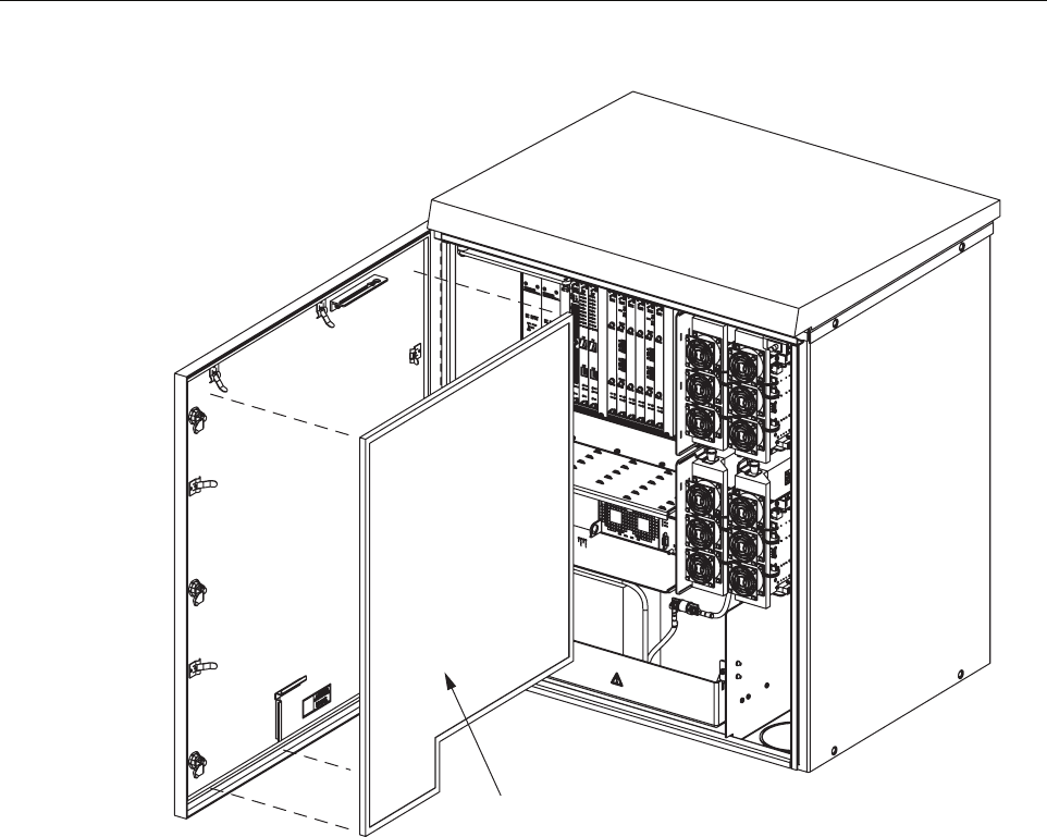
5.2 Cleaning or Replacing an Air Inlet Filter
The RAN cabinet air filter cleans the intake air before it enters the cabinets. The filter should be
cleaned approximately once per year and more often in extremely dirty environments. If the
cabinet temperature gradually rises over a long period of time and there are no fan failures, it is
possible that the filter is dirty and requires cleaning. Use the following procedure to clean the
cabinet air filter:
1. Open the RAN enclosure door and remove the inlet air filter tray door as shown in
Figure 48.
2. Pull the filter and away from its mounting slot at the bottom of the cabinet.
3. Gently tap the filter against your hand to dislodge the dirt. If necessary, use compressed air
or a vacuum cleaner to remove the dirt.
4. Carefully inspect the filter for holes or tears and replace if it is damaged.
5. Orient the filter with the airflow arrows pointed inside the RAN.
6. Close and secure the inlet air filter tray.
ADCP-75-210 • Issue 1 • November 2006
Page 71
© 2006, ADC Telecommunications, Inc.
Figure 48. Air Inlet Filter Tray
FILTER
21275-A
ADCP-75-210 • Issue 1 • November 2006
Page 72
© 2006, ADC Telecommunications, Inc.
6 CUSTOMER INFORMATION AND ASSISTANCE
© 2006, ADC Telecommunications, Inc.
All Rights Reserved
Printed in U.S.A.
13944-RM
WRITE:
ADC TELECOMMUNICATIONS, INC
PO BOX 1101,
MINNEAPOLIS, MN 55440-1101, USA
ADC TELECOMMUNICATIONS (S'PORE) PTE. LTD.
100 BEACH ROAD, #18-01, SHAW TOWERS.
SINGAPORE 189702.
ADC EUROPEAN CUSTOMER SERVICE, INC
BELGICASTRAAT 2,
1930 ZAVENTEM, BELGIUM
PHONE:
EUROPE
Sales Administration: +32-2-712-65 00
Technical Assistance: +32-2-712-65 42
EUROPEAN TOLL FREE NUMBERS
UK: 0800 960236
Spain: 900 983291
France: 0800 914032
Germany: 0180 2232923
U.S.A. OR CANADA
Sales: 1-800-366-3891 Extension 73000
Technical Assistance: 1-800-366-3891
Connectivity Extension 73475
Wireless Extension 73476
ASIA/PACIFIC
Sales Administration: +65-6294-9948
Technical Assistance: +65-6393-0739
ELSEWHERE
Sales Administration: +1-952-938-8080
Technical Assistance: +1-952-917-3475
Italy: 0800 782374
PRODUCT INFORMATION AND TECHNICAL ASSISTANCE:
Contents herein are current as of the date of publication. ADC reserves the right to change the contents without prior notice.
In no event shall ADC be liable for any damages resulting from loss of data, loss of use, or loss of profits and ADC further
disclaims any and all liability for indirect, incidental, special, consequential or other similar damages. This disclaimer of
liability applies to all products, publications and services during and after the warranty period. This publication may be
verified at any time by contacting ADC's Technical Assistance Center.
euro.tac@adc.com
asiapacific.tac@adc.com
wireless.tac@adc.com
connectivity.tac@adc.com