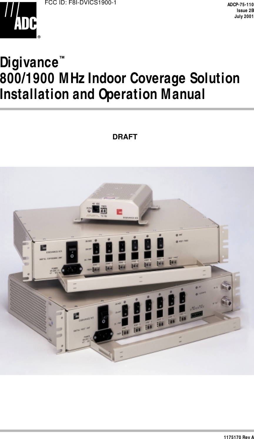
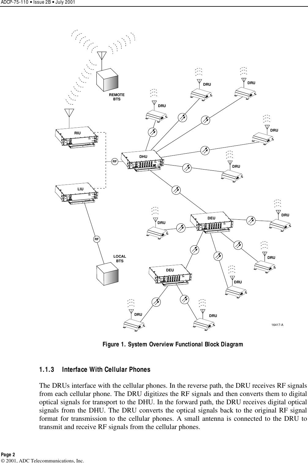
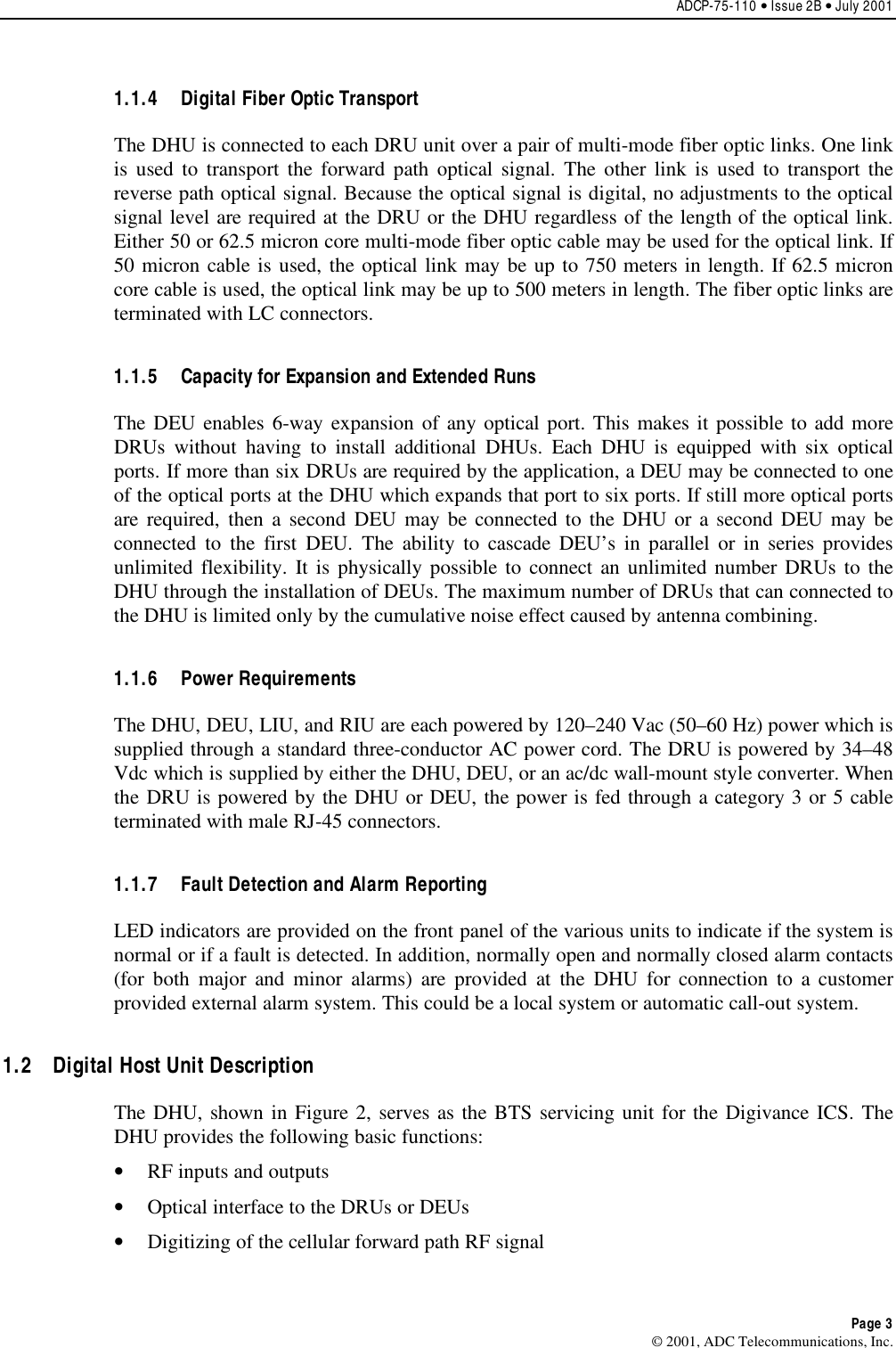
ADC Telecommunications DVICS1900-1 Digivance 1900 MHz Indoor Coverage Solution User Manual
ADC Telecommunications Inc Digivance 1900 MHz Indoor Coverage Solution
UserManual.wiki
>
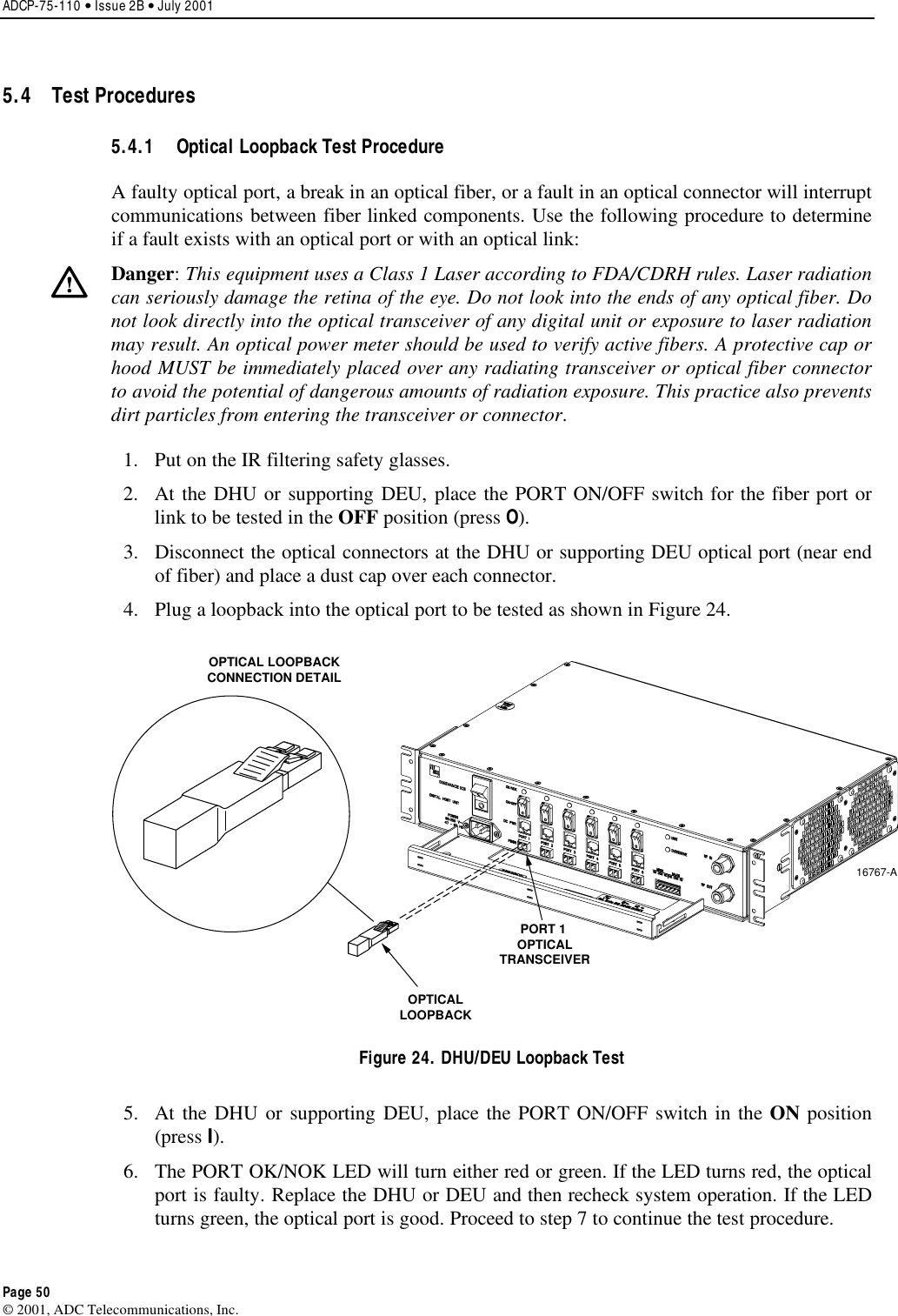
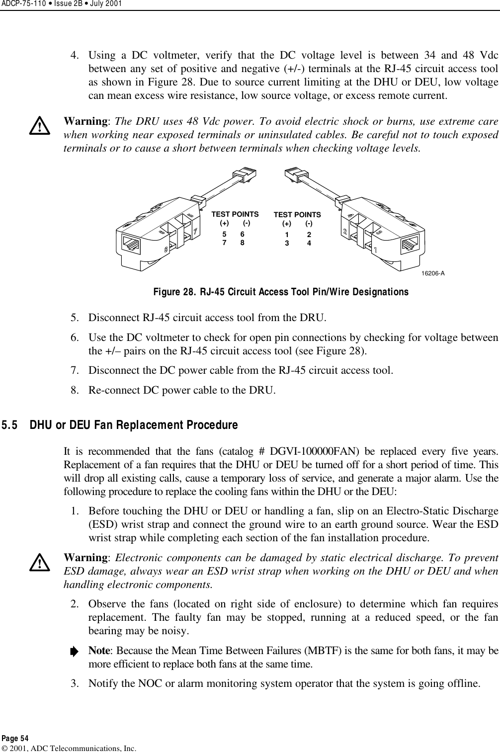
ADC Telecommunications
>
DVICS1900-1 User Manual
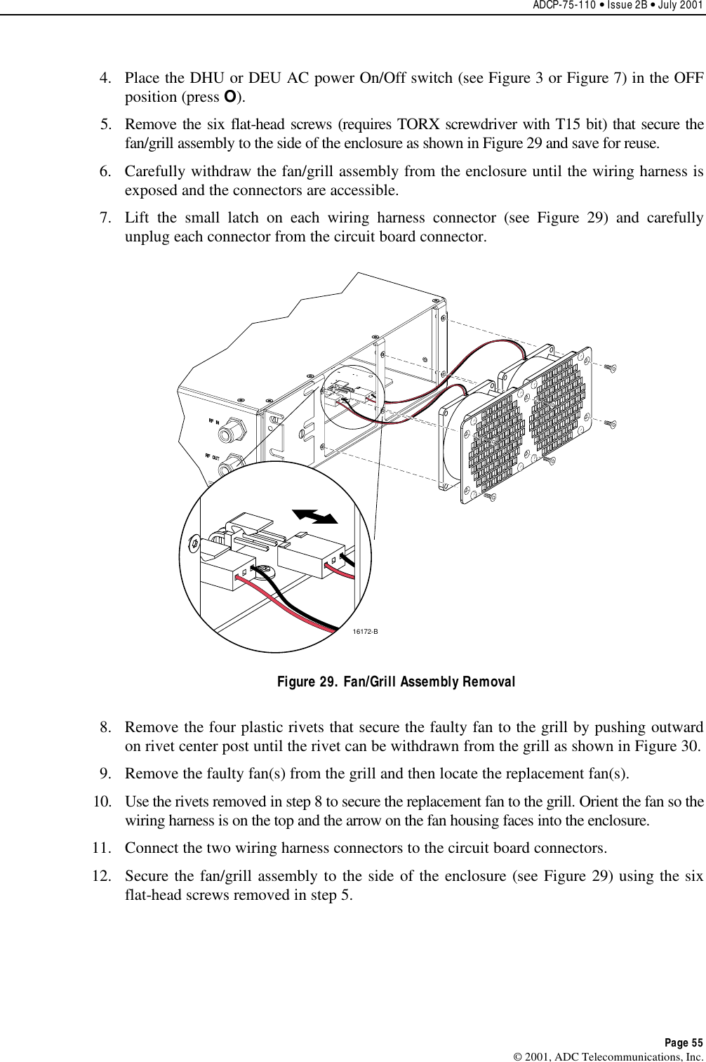
>
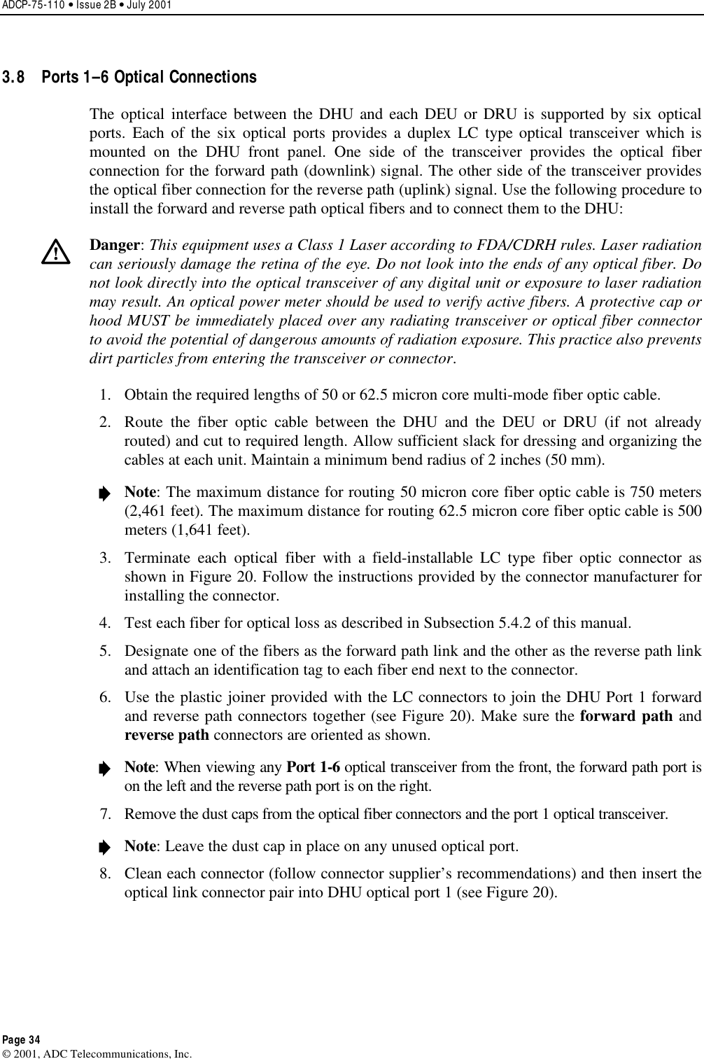
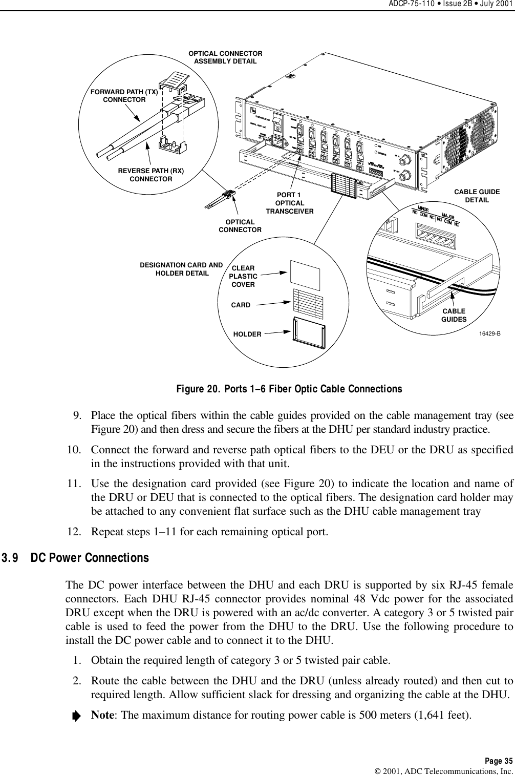
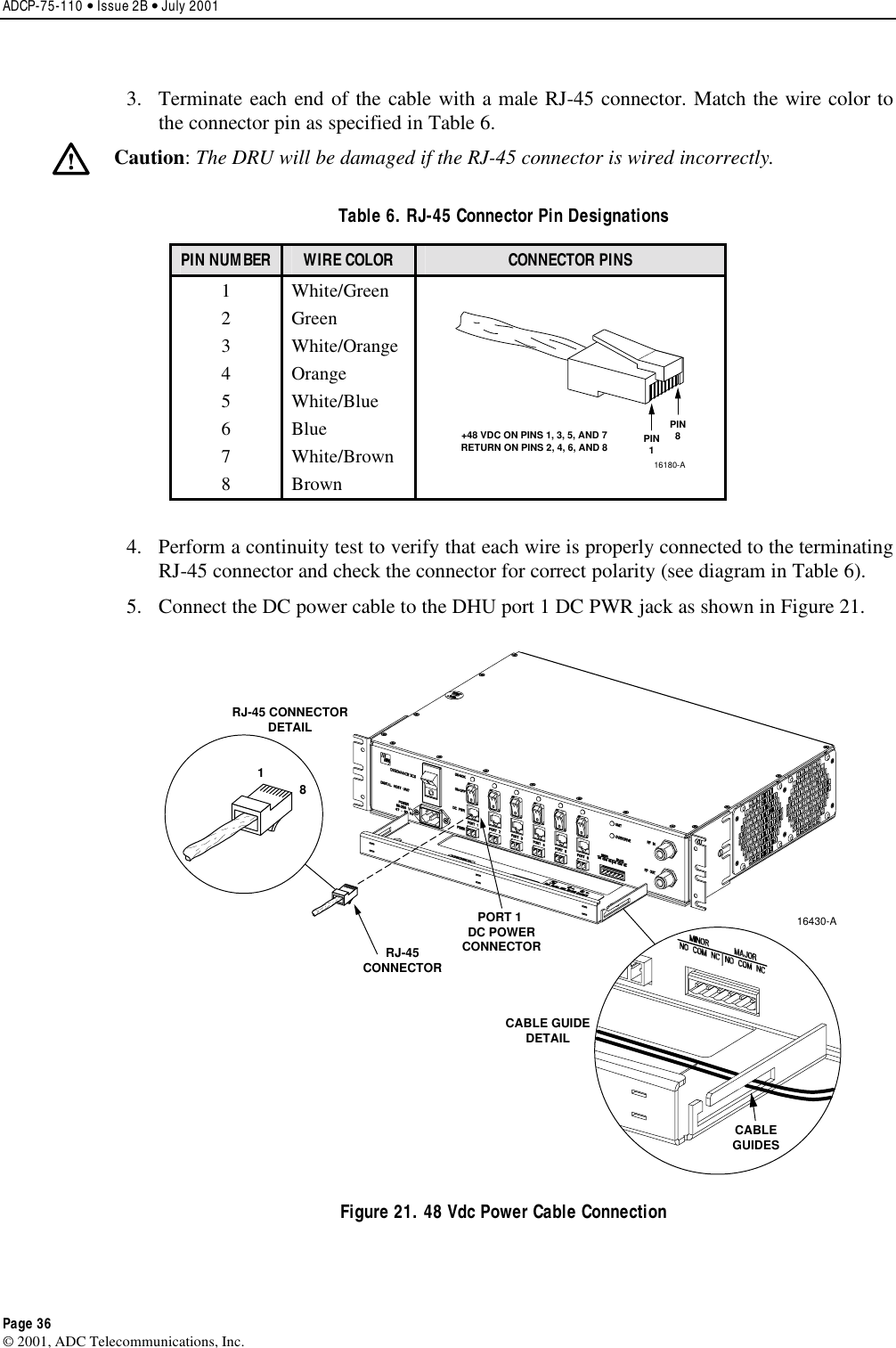
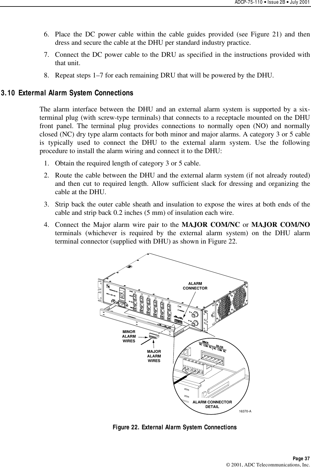
user manual
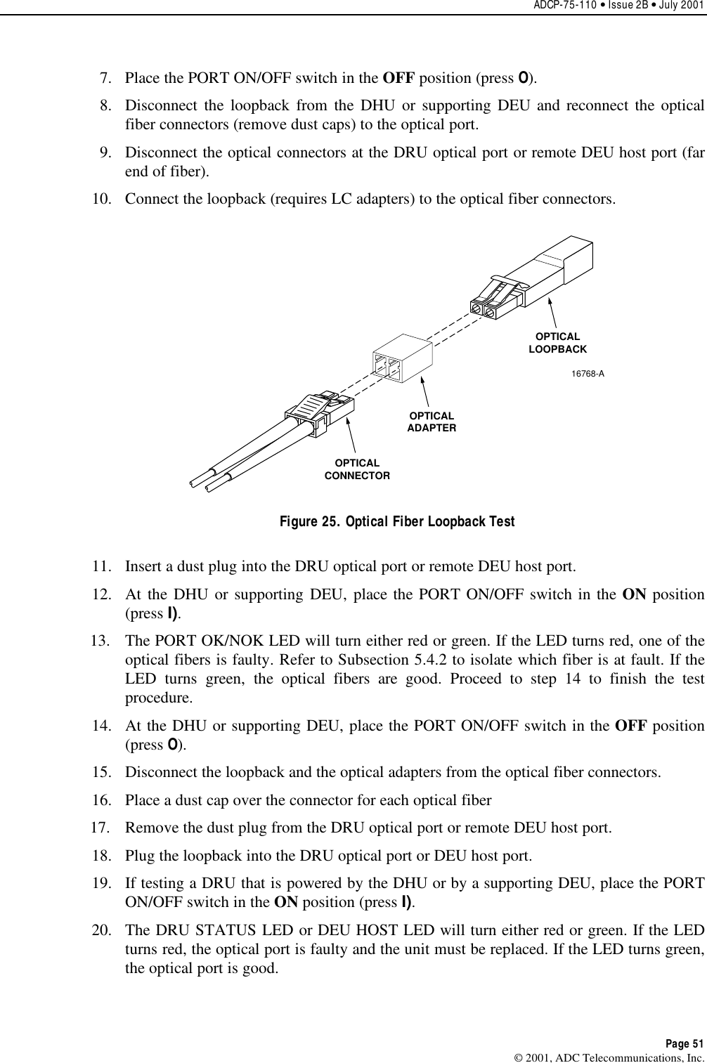
Contents
1.
user manual
2.
usermanual
3.
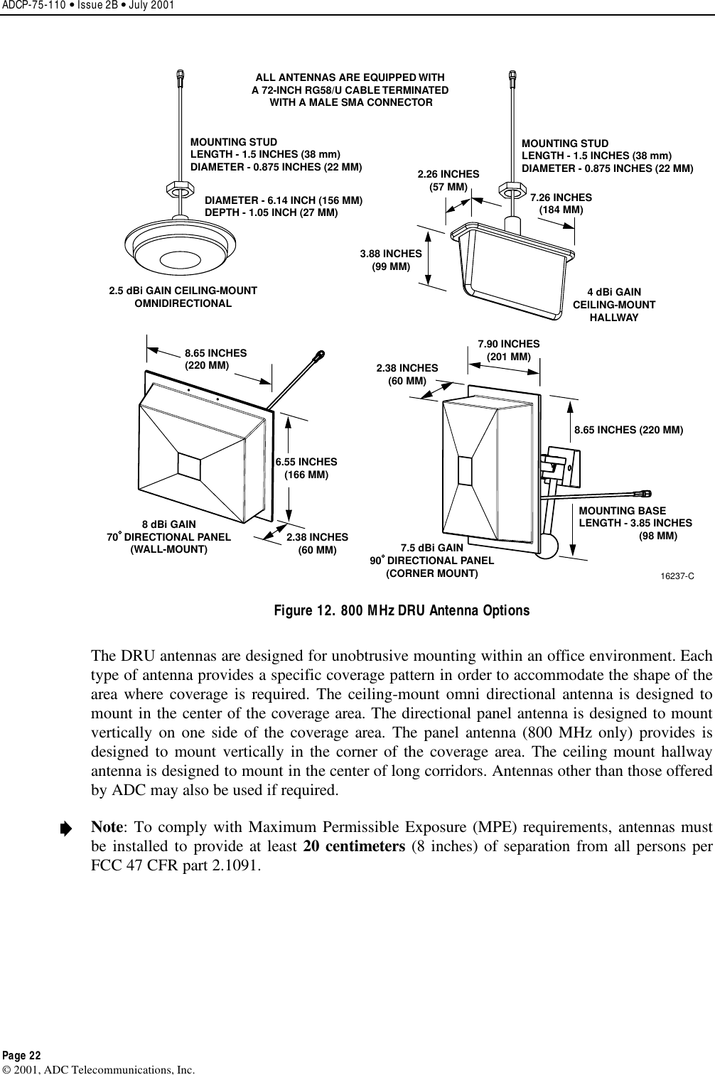
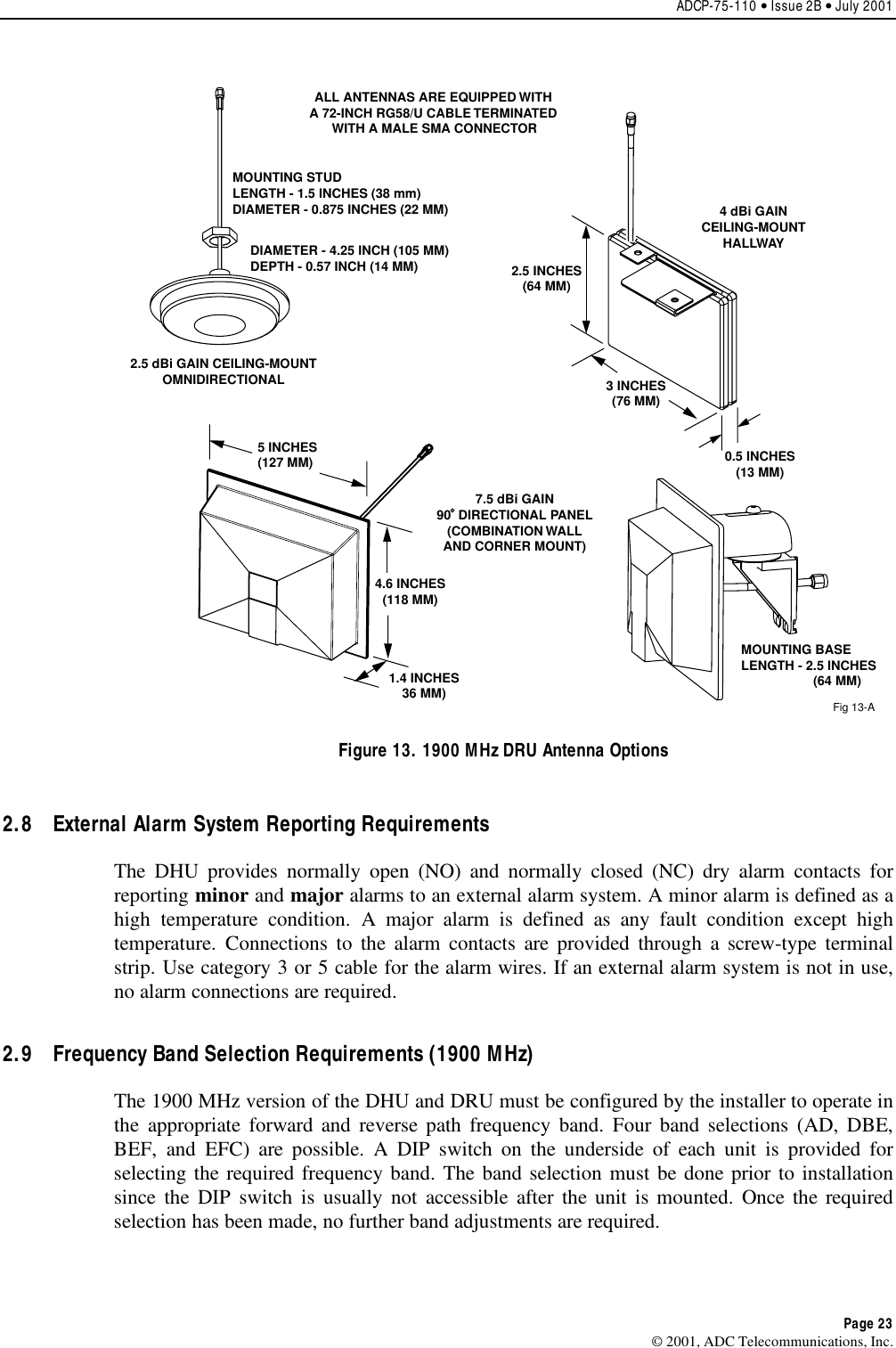
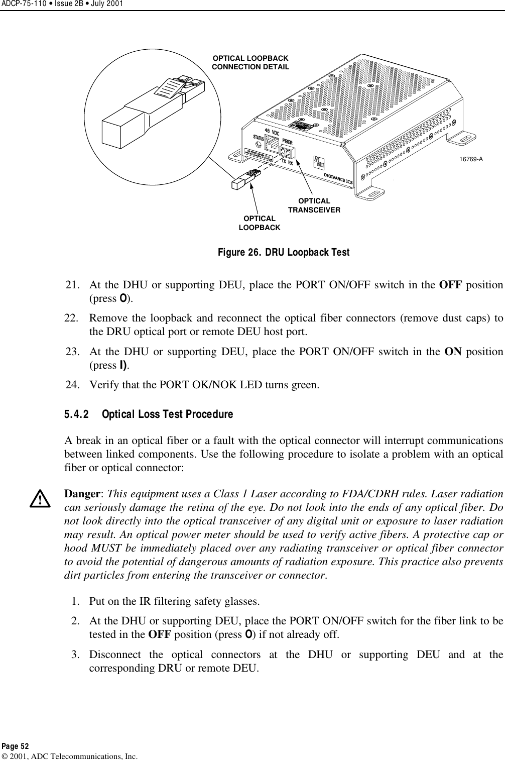
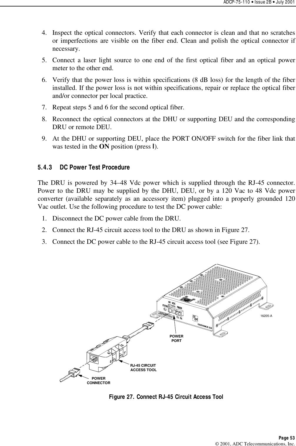
dru installation manual
user manual
usermanual
Navigation menu
Upload a User Manual
Namespaces
Wiki Guide
HTML
PDF
Info
Views
User Manual
Discussion / Help
Navigation