ADC Telecommunications DVICS1900-1 Digivance 1900 MHz Indoor Coverage Solution User Manual dru installation manual
ADC Telecommunications Inc Digivance 1900 MHz Indoor Coverage Solution dru installation manual
Contents
- 1. user manual
- 2. usermanual
- 3. dru installation manual
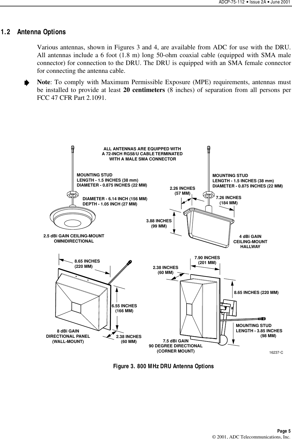
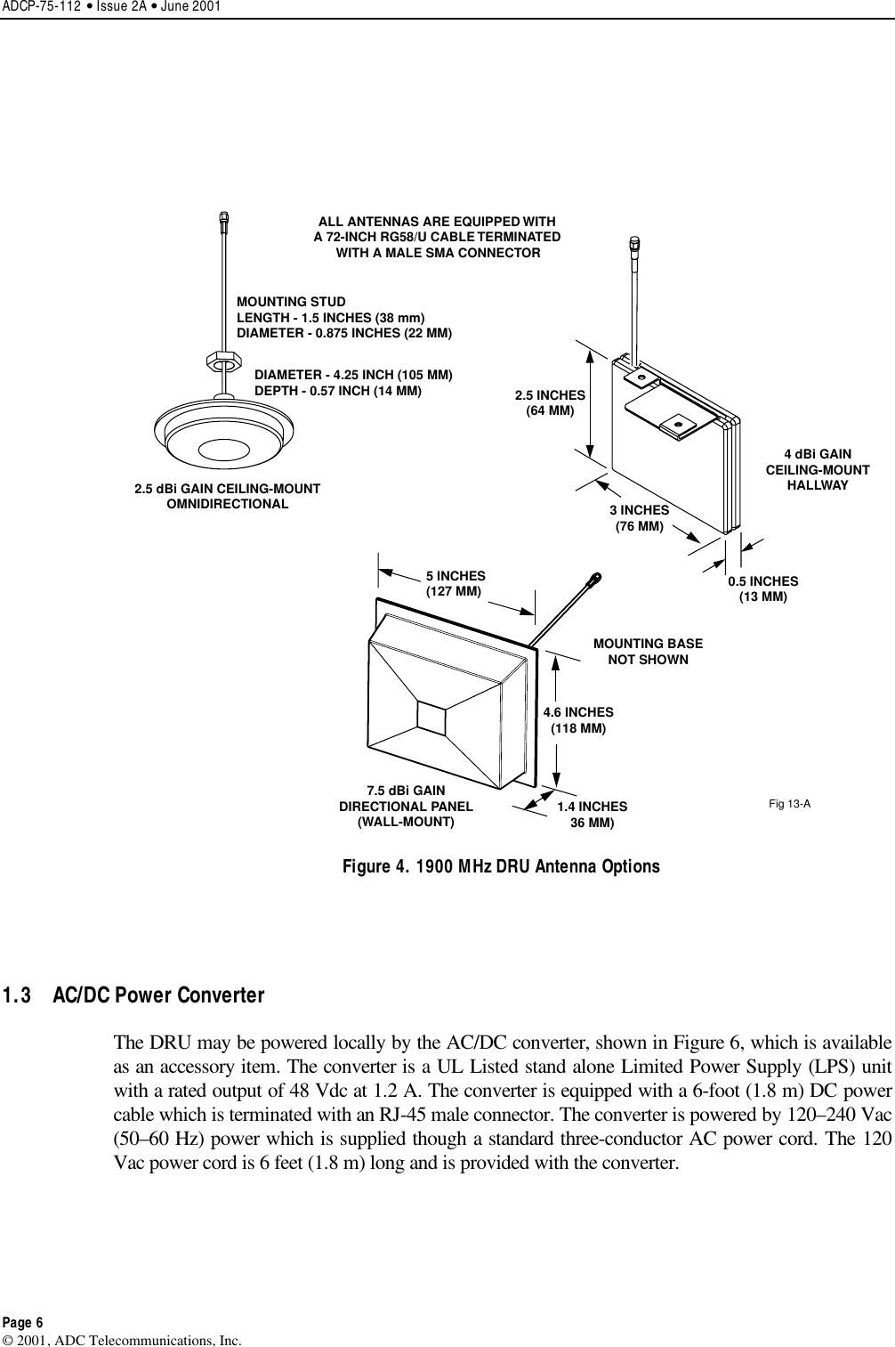
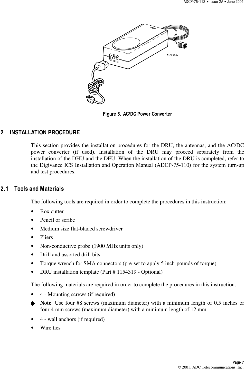
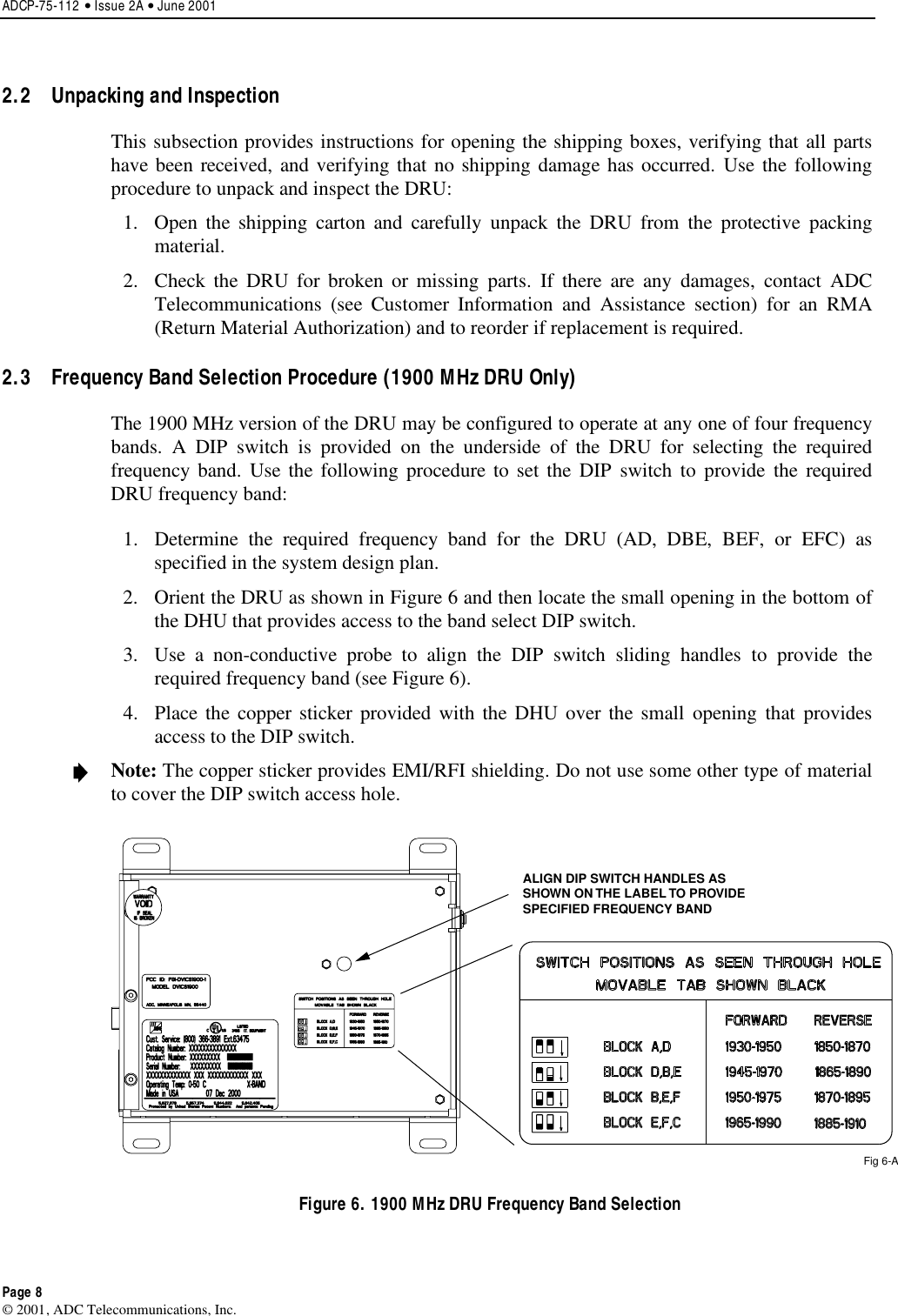
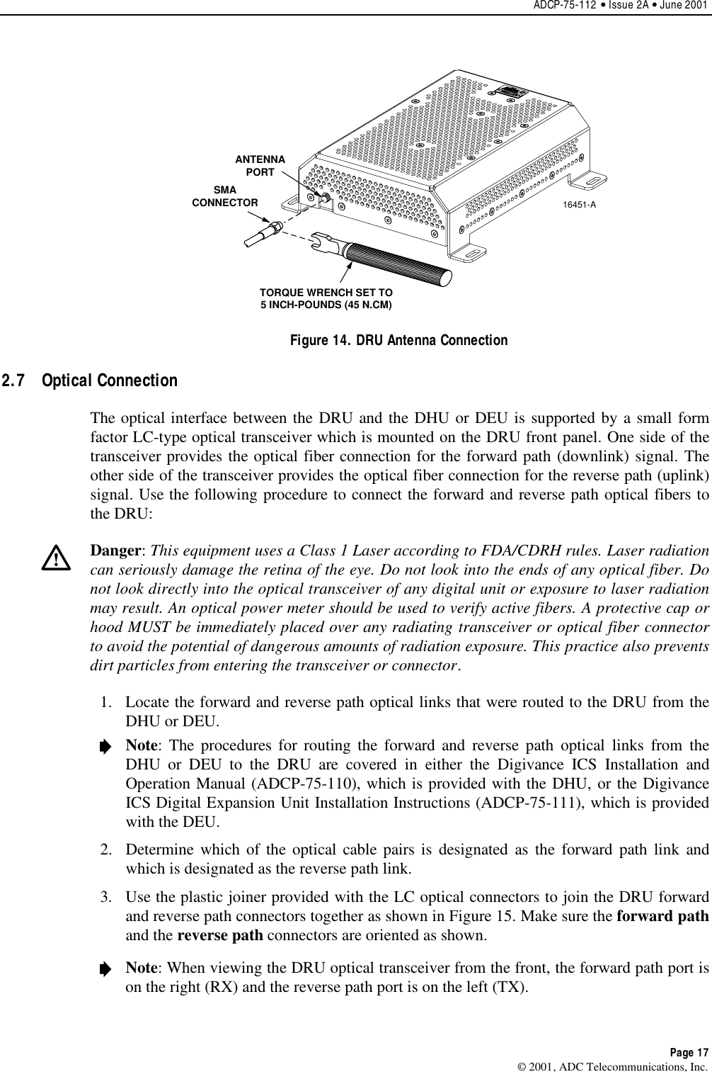
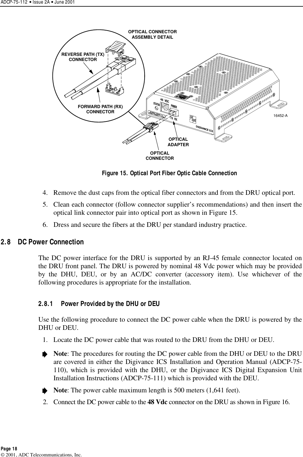
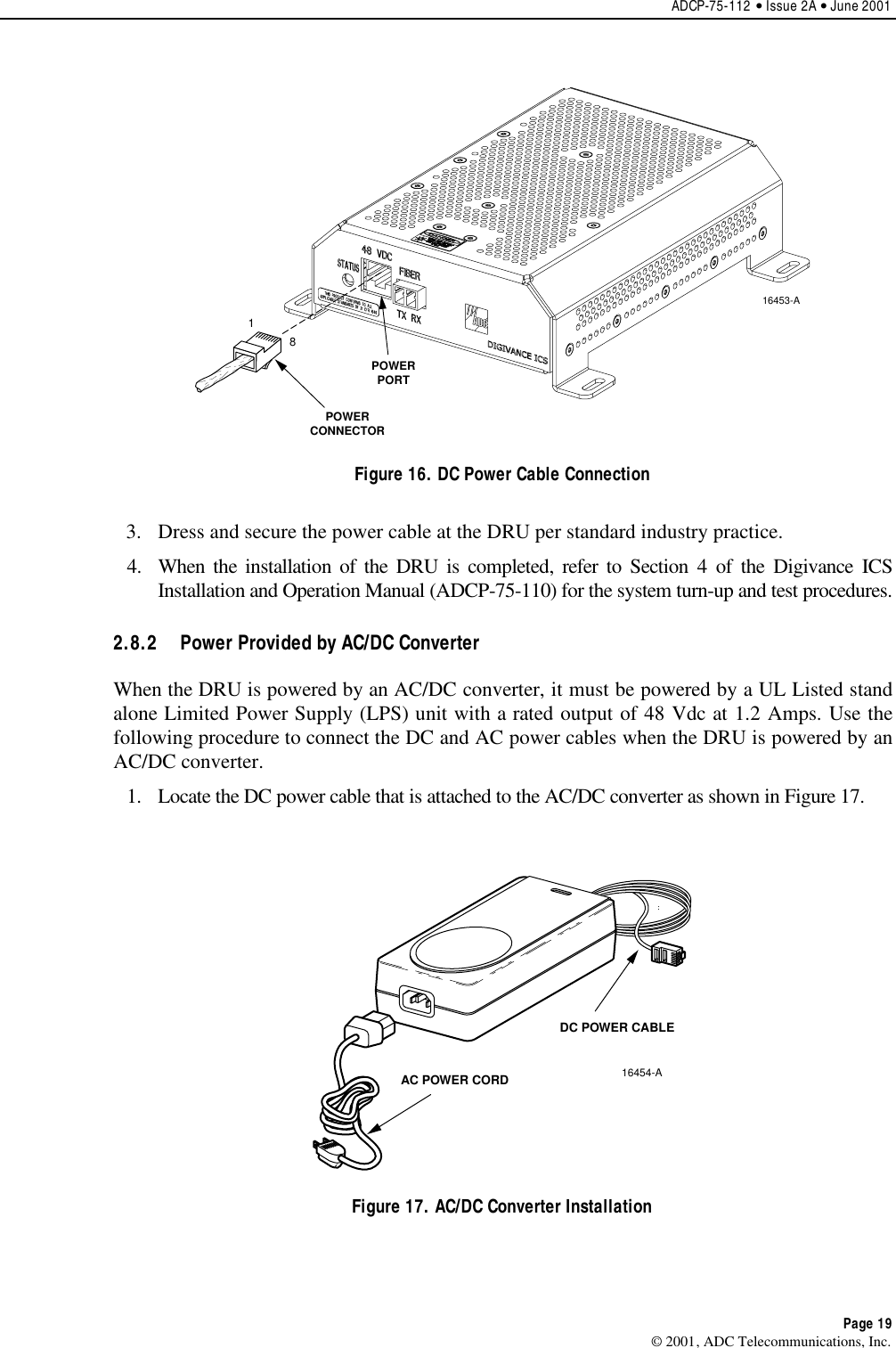
dru installation manual