ADC Telecommunications DVICS1900-1 Digivance 1900 MHz Indoor Coverage Solution User Manual dru installation manual
ADC Telecommunications Inc Digivance 1900 MHz Indoor Coverage Solution dru installation manual
Contents
- 1. user manual
- 2. usermanual
- 3. dru installation manual
dru installation manual
ADCP-75-112 •
••
• Issue 2A •
••
• June 2001
TBD Rev A Page 1
© 2001, ADC Telecommunications, Inc.
Digivance™ Indoor Coverage Solution
800/1900 MHz Digital Remote Unit
Installation Instructions
Content Page
INTRODUCTION............................................................................2
1 DESCRIPTION........................................................................3
1.1 Digital Remote Unit ..............................................................3
1.2 Antenna Options ................................................................5
1.3 AC/DC Power Converter............................................................6
2 INSTALLATION PROCEDURE ..............................................................7
2.1 Tools and Materials ..............................................................7
2.2 Unpacking and Inspection ..........................................................8
2.3 Frequency Band Selection (1900 DRU Only) .............................................8
2.4 DRU Mounting Procedure ..........................................................9
2.5 Antenna Mounting Procedure....................................................... 10
2.6 Antenna Connection ............................................................. 16
2.7 Optical Connection.............................................................. 17
2.8 DC Power Connection ............................................................ 18
3 CUSTOMER INFORMATION AND ASSISTANCE.................................................. 21
DRAFT
16449-A
Digital Remote Unit
ADCP-75-112 • Issue 2A • June 2001
Page 2
© 2001, ADC Telecommunications, Inc.
INTRODUCTION
This publication provides instructions for installing the Digivance Indoor Coverage Solution
(ICS) Digital Remote Unit (DRU). Amore complete description of the DRU along with the
operating and maintenance procedures is provided in the Digivance ICS Installation and
Operation Manual (ADCP-75-110). The DRU is installed in conjunction with the Digital Host
Unit (DHU) and the Digital Expansion Unit (DEU).
Revision History
ISSUE DATE REASON FOR CHANGE
Issue 1 04/2001 Original release.
Issue 2 06/2001 Changes in LED operation and new power cable maximum length recommendations
Issue 2A 06/2001 Updated to cover 1900 MHz version of product
Trademark Information
ADC is aregistered trademark of ADC Telecommunications, Inc.
Digivance is atrademark of ADC Telecommunications, Inc.
LC is atrademark of Lucent Technologies Inc.
Admonishments
Important safety admonishments are used throughout this publication to warn of possible
hazards to persons or equipment. An admonishment identifies apossible hazard and then
explains what may happen if the hazard is not avoided. The admonishments —in the form of
Dangers, Warnings, and Cautions —must be followed at all times. These warnings are
flagged by use of the triangular alert icon (seen below), and are listed in descending order of
severity of injury or damage and likelihood of occurrence.
Danger:Danger is used to indicate the presence of a hazard that will cause severe personal
injury, death, or substantial property damage if the hazard is not avoided.
Warning:Warning is used to indicate the presence of a hazard that can cause severe
personal injury, death, or substantial property damage if the hazard is not avoided.
Caution:Caution is used to indicate the presence of a hazard that will or can cause minor
personal injury or property damage if the hazard is not avoided.
Related Publications
Listed below are related manuals and their publication numbers. Copies of these publications
can be ordered by contacting the ADC Technical Assistance Center at 1-800-366-3891
extension 63475 (in U.S.A. or Canada) or 952-946-3475 (outside U.S.A. and Canada).
Title ADCP Number
Digivance ICS Installation and Operation Manual 75-110
Digivance ICS Digital Expansion Unit Installation Instructions 75-111
ADCP-75-112 • Issue 2A • June 2001
Page 3
© 2001, ADC Telecommunications, Inc.
1 DESCRIPTION
This section describes the DRU, the various DRU antennas, and the AC/DC power converter
(optional accessory item).
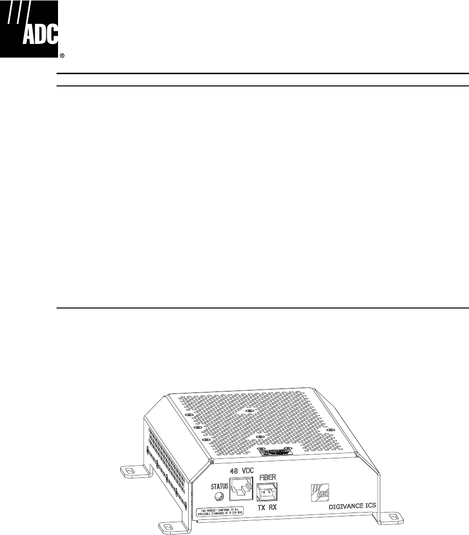
1.1 Digital Remote Unit
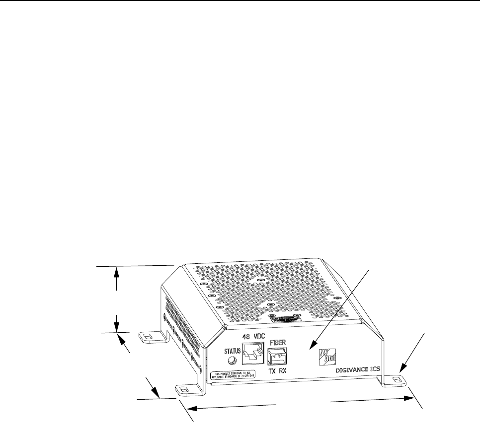
The DRU, shown in Figure 1, serves as the cellular user servicing unit for the Digivance ICS.
The DRU consists of an electronic circuit board assembly that is mounted within apowder-
coated sheet metal enclosure. The electronic circuit board assembly is not user replaceable.
The DRU is designed for use within anon-condensing indoor environment such as inside a
building. All controls, indicators, and connectors (except the antenna connector) are mounted
on the DRU front panel for convenient access.
FRONT PANEL
MOUNTING FOOT
(EACH CORNER)
7.0 INCHES
(178 mm)
7.3 INCHES
(185 mm)
2.1 INCHES
(53 mm)
16420-A
Figure 1. Digital Remote Unit
The DRU is equipped with four integral mounting feet that allow it to be mounted on any flat
horizontal or vertical surface. Atypical location for mounting the DRU would be above
ceiling tiles where the optical fiber and power cables can be concealed or on a wall. Slots are
provided in the mounting feet for securing the DRU to the mounting surface.
The RF signal interface between the DRU and the cellular users is provided through an
external antenna connected to afemale SMA connector. The antenna may be ordered
separately from ADC. Several types of antennas with various patterns are available. Non-ADC
antennas may also be used with the DRU to meet various application requirements.
The DRU is equipped with asmall form factor LC type optical transceiver that provides a
point for connecting the optical link cables. Depending on the application requirements, the
optical transceiver may be connected to either a DHU or a DEU.
ADCP-75-112 • Issue 2A • June 2001
Page 4
© 2001, ADC Telecommunications, Inc.
The DRU is equipped with afemale RJ-45 jack that provides apoint for connecting aDC
power cable. The DRU is powered by 34–48 Vdc power which is supplied through the RJ-45
connector. Power to the DRU may be supplied by the DHU, DEU, or by a 120 Vac to 48 Vdc
power converter (available separately as an accessory item) plugged into a properly grounded
120 Vac outlet. The AC/DC converter is aUL Listed stand alone Limited Power Supply (LPS)
unit with arated output of 48 Vdc at 1.2 A. When powered by the DHU or DEU, acategory 3
or 5 twisted-pair cable terminated with RJ-45 connectors is required. The recommended
maximum length of the power cable is 500 meters (1,641 feet). Any distance beyond 500
meters requires powering by the AC/DC converter.
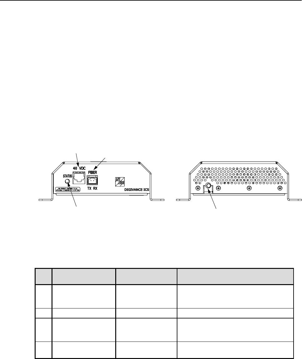
The DRU user interface consists of the connectors and the LED that are provided on the DRU
front and rear panels. The DRU user interface points are indicated in Figure 2 and described in
Table 1.
16421-A
REAR VIEWFRONT VIEW
(4) ANTENNA CONNECTOR
(1) STATUS LED
(2) 48 VDC POWER
CONNECTOR (3) FIBER LINK
OPTICAL ADAPTERS
TX-LEFT - RX-RIGHT
Figure 2. Digital Remote Unit User Interface
Table 1. Digital Remote Unit User Interface
REF
No. USER INTERFACE
DESIGNATION DEVICE FUNCTIONAL
DESCRIPTION
1 STATUS Multi-colored LED
(Red/Green/Yellow) Indicates if the status of the DRU is
normal or faulty or if the forward path
optical input is normal or lost. (see Note)
248Vdc RJ-45 jack (female) Used for connecting a DC power cable.
3 FIBER
TX RX Small form factor
LC-type optical
transceiver
Used for connecting the forward path
and reverse path optical links.
4 – SMA-type coaxial
connector (female) Used for connecting the antenna coaxial
cable lead.
Note: A detailed description of DEU LED operation is provided in the Digivance ICS
Installation and Operation Manual (ADCP-75-110)
ADCP-75-112 • Issue 2A • June 2001
Page 5
© 2001, ADC Telecommunications, Inc.
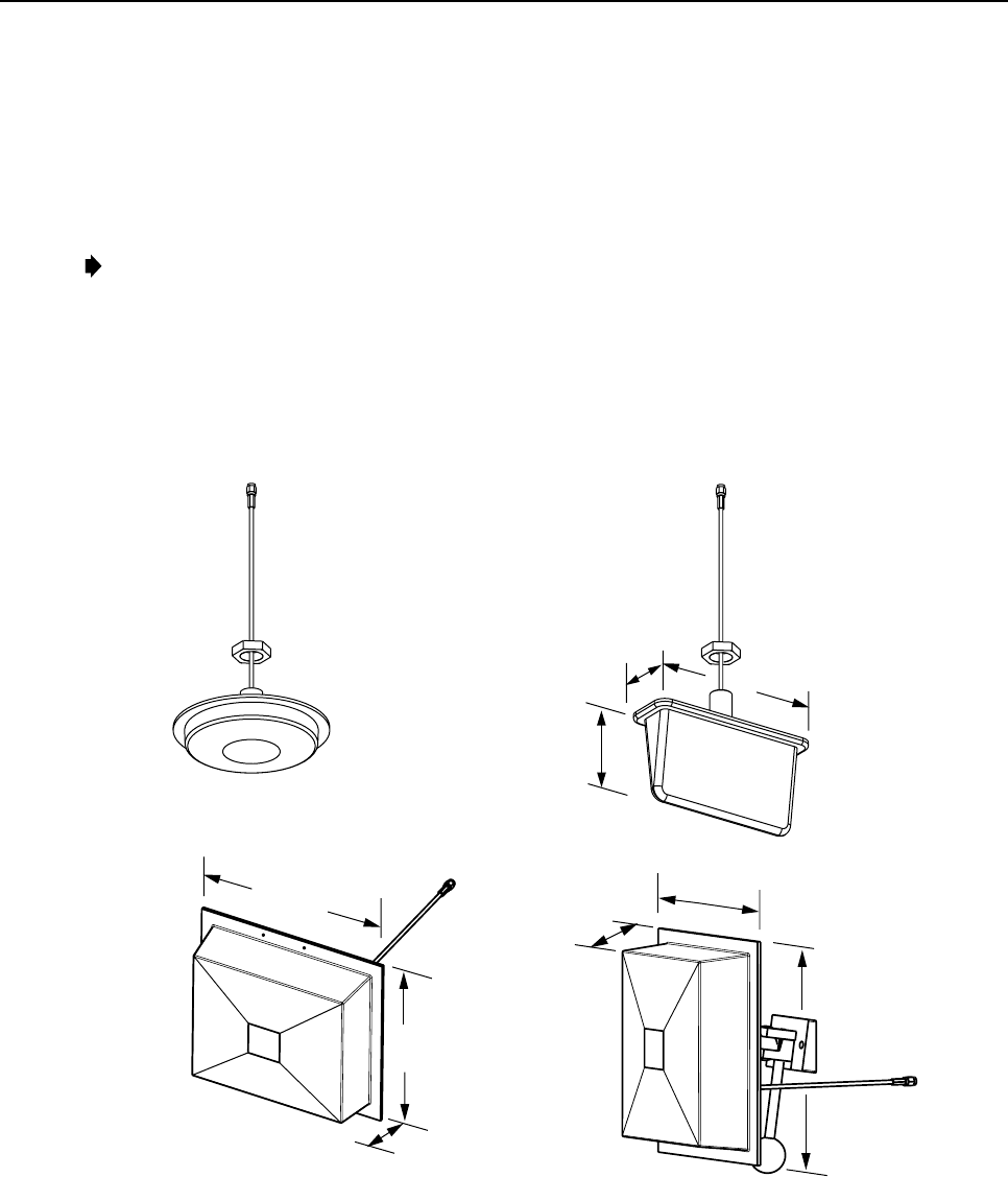
1.2 Antenna Options
Various antennas, shown in Figures 3 and 4, are available from ADC for use with the DRU.
All antennas include a 6 foot (1.8 m) long 50-ohm coaxial cable (equipped with SMA male
connector) for connection to the DRU. The DRU is equipped with an SMA female connector
for connecting the antenna cable.
Note:To comply with Maximum Permissible Exposure (MPE) requirements, antennas must
be installed to provide at least 20 centimeters (8 inches) of separation from all persons per
FCC 47 CFR Part 2.1091.
DIAMETER - 6.14 INCH (156 MM)
DEPTH - 1.05 INCH (27 MM)
7.26 INCHES
(184 MM)
3.88 INCHES
(99 MM)
2.26 INCHES
(57 MM)
8.65 INCHES
(220 MM)
6.55 INCHES
(166 MM)
2.38 INCHES
(60 MM)
7.90 INCHES
(201 MM)
2.38 INCHES
(60 MM)
8.65 INCHES (220 MM)
4 dBi GAIN
CEILING-MOUNT
HALLWAY
2.5 dBi GAIN CEILING-MOUNT
OMNIDIRECTIONAL
8 dBi GAIN
DIRECTIONAL PANEL
(WALL-MOUNT) 7.5 dBi GAIN
90 DEGREE DIRECTIONAL
(CORNER MOUNT)
MOUNTING STUD
LENGTH - 3.85 INCHES
(98 MM)
ALL ANTENNAS ARE EQUIPPED WITH
A 72-INCH RG58/U CABLE TERMINATED
WITH A MALE SMA CONNECTOR
MOUNTING STUD
LENGTH - 1.5 INCHES (38 mm)
DIAMETER - 0.875 INCHES (22 MM)
MOUNTING STUD
LENGTH - 1.5 INCHES (38 mm)
DIAMETER - 0.875 INCHES (22 MM)
16237-C
Figure 3. 800 MHz DRU Antenna Options
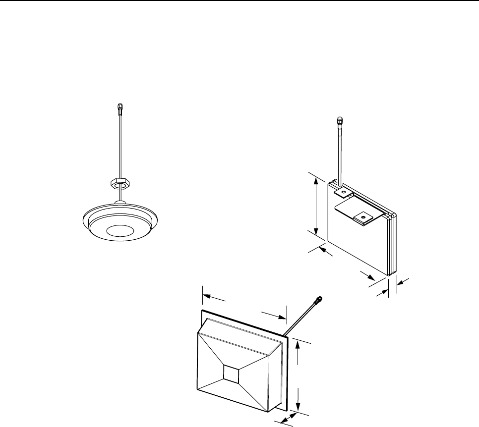
ADCP-75-112 • Issue 2A • June 2001
Page 6
© 2001, ADC Telecommunications, Inc.
DIAMETER - 4.25 INCH (105 MM)
DEPTH - 0.57 INCH (14 MM) 2.5 INCHES
(64 MM)
0.5 INCHES
(13 MM)
3 INCHES
(76 MM)
5 INCHES
(127 MM)
4.6 INCHES
(118 MM)
1.4 INCHES
36 MM)
4 dBi GAIN
CEILING-MOUNT
HALLWAY
2.5 dBi GAIN CEILING-MOUNT
OMNIDIRECTIONAL
7.5 dBi GAIN
DIRECTIONAL PANEL
(WALL-MOUNT)
ALL ANTENNAS ARE EQUIPPED WITH
A 72-INCH RG58/U CABLE TERMINATED
WITH A MALE SMA CONNECTOR
MOUNTING STUD
LENGTH - 1.5 INCHES (38 mm)
DIAMETER - 0.875 INCHES (22 MM)
Fig 13-A
MOUNTING BASE
NOT SHOWN
Figure 4. 1900 MHz DRU Antenna Options
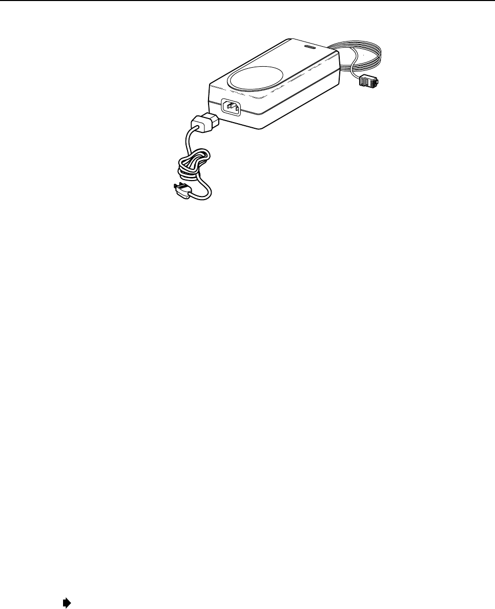
1.3 AC/DC Power Converter
The DRU may be powered locally by the AC/DC converter, shown in Figure 6, which is available
as an accessory item. The converter is aUL Listed stand alone Limited Power Supply (LPS) unit
with arated output of 48 Vdc at 1.2 A. The converter is equipped with a6-foot (1.8 m) DC power
cable which is terminated with an RJ-45 male connector. The converter is powered by 120–240 Vac
(50–60 Hz) power which is supplied though astandard three-conductor AC power cord. The 120
Vac power cord is 6feet (1.8 m) long and is provided with the converter.
ADCP-75-112 • Issue 2A • June 2001
Page 7
© 2001, ADC Telecommunications, Inc.
15988-A
Figure 5. AC/DC Power Converter
2 INSTALLATION PROCEDURE
This section provides the installation procedures for the DRU, the antennas, and the AC/DC
power converter (if used). Installation of the DRU may proceed separately from the
installation of the DHU and the DEU. When the installation of the DRU is completed, refer to
the Digivance ICS Installation and Operation Manual (ADCP-75-110) for the system turn-up
and test procedures.
2.1 Tools and Materials
The following tools are required in order to complete the procedures in this instruction:
• Box cutter
• Pencil or scribe
• Medium size flat-bladed screwdriver
• Pliers
• Non-conductive probe (1900 MHz units only)
• Drill and assorted drill bits
• Torque wrench for SMA connectors (pre-set to apply 5 inch-pounds of torque)
• DRU installation template (Part # 1154319 - Optional)
The following materials are required in order to complete the procedures in this instruction:
• 4 - Mounting screws (if required)
Note:Use four #8 screws (maximum diameter) with aminimum length of 0.5 inches or
four 4 mm screws (maximum diameter) with a minimum length of 12 mm
• 4 - wall anchors (if required)
• Wire ties
ADCP-75-112 • Issue 2A • June 2001
Page 8
© 2001, ADC Telecommunications, Inc.
2.2 Unpacking and Inspection
This subsection provides instructions for opening the shipping boxes, verifying that all parts
have been received, and verifying that no shipping damage has occurred. Use the following
procedure to unpack and inspect the DRU:
1. Open the shipping carton and carefully unpack the DRU from the protective packing
material.
2. Check the DRU for broken or missing parts. If there are any damages, contact ADC
Telecommunications (see Customer Information and Assistance section) for an RMA
(Return Material Authorization) and to reorder if replacement is required.
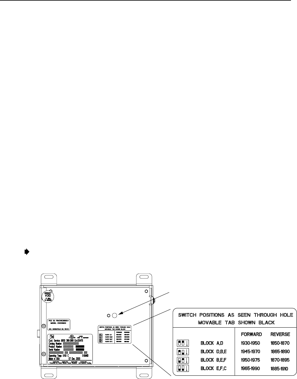
2.3 Frequency Band Selection Procedure (1900 MHz DRU Only)
The 1900 MHz version of the DRU may be configured to operate at any one of four frequency
bands. ADIP switch is provided on the underside of the DRU for selecting the required
frequency band. Use the following procedure to set the DIP switch to provide the required
DRU frequency band:
1. Determine the required frequency band for the DRU (AD, DBE, BEF, or EFC) as
specified in the system design plan.
2. Orient the DRU as shown in Figure 6 and then locate the small opening in the bottom of
the DHU that provides access to the band select DIP switch.
3. Use anon-conductive probe to align the DIP switch sliding handles to provide the
required frequency band (see Figure 6).
4. Place the copper sticker provided with the DHU over the small opening that provides
access to the DIP switch.
Note: The copper sticker provides EMI/RFI shielding. Do not use some other type of material
to cover the DIP switch access hole.
ALIGN DIP SWITCH HANDLES AS
SHOWN ON THE LABEL TO PROVIDE
SPECIFIED FREQUENCY BAND
Fig 6-A
Figure 6. 1900 MHz DRU Frequency Band Selection

ADCP-75-112 • Issue 2A • June 2001
Page 9
© 2001, ADC Telecommunications, Inc.
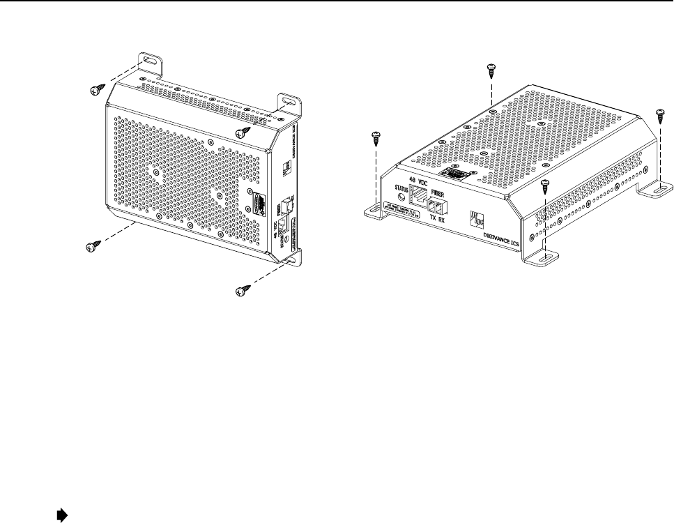
2.4 DRU Mounting Procedure
The DRU may be mounted on any flat vertical or horizontal surface. Aslot is provided in each
of the four mounting feet for inserting afastener. The fasteners must be provided by the
installer. Use the following procedure to mount the DRU:
Warning:Wet conditions increase the potential for receiving an electrical shock when
installing or using electrically-powered equipment. To prevent electrical shock, never install
or use electrical equipment in a wet location or during a lightning storm.
Note: To insure that all optical connectors and transceivers remain dust-free during installation,
leave all dust caps and dust protectors in place until directed to remove them for connection.
1. Obtain the appropriate fasteners (lag bolts, screws, wall anchors, etc.) for securing the
DRU to the mounting surface.
2. Position the DRU on the mounting surface in the specified location (per the system
design). Make sure the LED will be visible when the unit is mounted.
Note:To ensure there is adequate air circulation for cooling, provide aminimum of 3
inches (76 mm) of clearance space on all sides of the DRU (except the bottom). In
addition, at least one surface of the DRU installation area must be open to the building’s
interior air space. If aportable/flexible antenna will be installed, allow aminimum of 9
inches (229 mm) clearance along the surface with the antenna.
Note:In mounting situations where fiber, power, and coaxial cable pass-through holes
are planned, it is critical that these holes be placed far enough away from their respective
connectors to avoid forming overly tight bend radii. Tight bend radii can damage fiber
optic cable and reduce RF signal levels. The DRU mounting template (part # 1154319)
provides the clearances for the following cable types:
Power cable (cat 3 and 5): 0.2 inch (5.2 mm) diameter
Fiber optic cable (twin lead): 0.12 inch (3.0 mm) diameter
Antenna coaxial cable: 0.16 inch (4.0 mm) diameter
If planned cable diameters are greater than those listed, please consult with the cable
manufacturer to determine the cable’s recommended minimum bend radii.
3. Mark the location of the mounting holes and of any pass-through holes that may be
required for fiber, power, or coaxial cables. Observe any additional instructions that may
be printed on the template such as the recommended fasteners and clearance
requirements.
4. Drill appropriately sized holes in the mounting surface for the mounting screws or wall
anchors and for the fiber, power, or coaxial cables (if pass-through holes are required).
5. Place the DRU in position for mounting and then install the fasteners as shown in Figure 7.
6. Securely tighten each fastener.
ADCP-75-112 • Issue 2A • June 2001
Page 10
© 2001, ADC Telecommunications, Inc.
16450-A
VERTICAL MOUNT HORIZONTAL MOUNT
NOTE: THE DRU FRONT PANEL MAY ALSO BE
ORIENTED DOWNWARD FOR VERTICAL MOUNT
Figure 5. DRU Mounting
2.5 Antenna Mounting Procedure
Various types of antennas are available from ADC for use with the DRU. All antennas include
a 6-foot (1.8 m) long 50-ohm coaxial cable for connection to the DRU. Each type of antenna
provides aspecific coverage pattern in order to accommodate the shape of the area where
coverage is required. Mount the antenna in the location specified in the system design and
orient according to the coverage pattern required.
Note:To comply with Maximum Permissible Exposure (MPE) requirements, antennas must
be installed to provide at least 20 centimeters (8 inches) of separation from all persons per
FCC 47 CFR Part 2.1091.
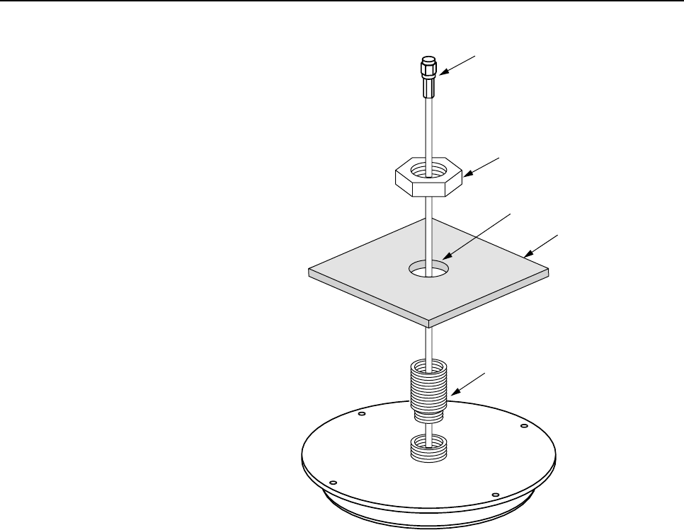
2.5.1 800 and 1900 MHz Ceiling-Mount Omnidirectional Antenna
The 800 and 1900 MHz ceiling-mount omnidirectional antennas are designed to mount in the center
of the coverage area. Mount the ceiling-mount omnidirectional antenna as shown in Figure 8and as
described in the following procedure.
1. Remove ceiling tile.
2. Drill 1-inch (25 mm) hole in center of tile.
3. Insert antenna cable through hole.
4. Insert threaded stud on base of antenna through hold.
5. Secure antenna to ceiling tile with nylon jam nut.
6. Replace ceiling tile.
7. Route antenna cable to DRU.
ADCP-75-112 • Issue 2A • June 2001
Page 11
© 2001, ADC Telecommunications, Inc.
16244-A
THREADED SPACER
(REMOVE IF NOT NEEDED)
CEILING
TILE
7/8-14 NYLON HEX
JAM NUT
I-INCH (25 mm)
DIAMETER HOLE
SMA CONNECTOR
NOTE: TO COMPLY WITH MAXIMUM
PERMISSIBLE EXPOSURE (MPE) REQUIREMENTS,
ANTENNAS MUST BE INSTALLED TO PROVIDE AT
LEAST 20 CENTIMETERS OF SEPARATION FROM
ALL PERSONS PER FCC 47 CFR PART 2.1091.
Figure 8. 800 and 1900 MHz Ceiling-Mount Omnidirectional Antenna Installation
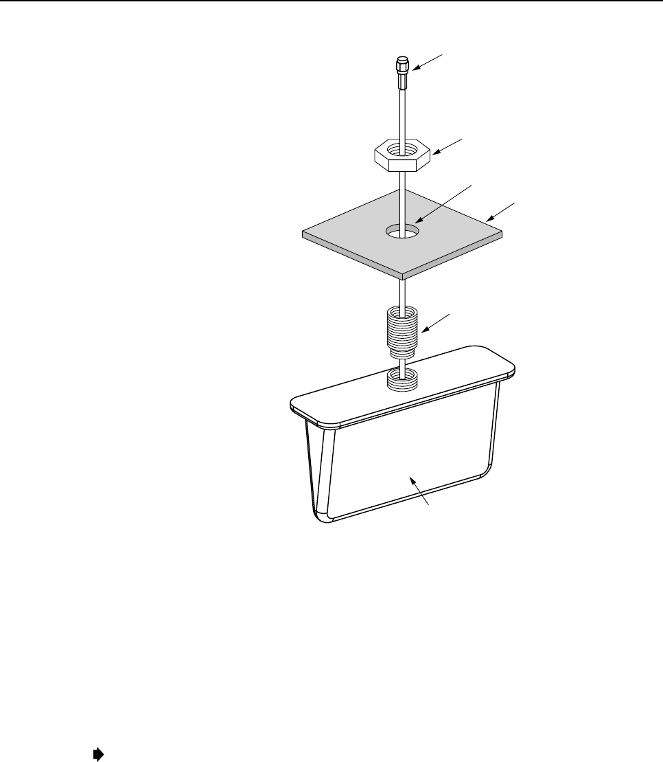
2.5.2 800 MHz Ceiling-Mount Hallway Antenna
The 800 MHz ceiling mount hallway antenna is designed to mount in the center of long
corridors. Mount the ceiling-mount hallway antenna as shown in Figure 9 and as described in
the following procedure:
1. Remove ceiling tile.
2. Drill 1-inch (25 mm) hole in center of tile.
3. Insert antenna cable through hole.
4. Insert threaded stud on base of antenna through hole.
5. Secure antenna to ceiling tile with nylon jam nut.
6. Orient antenna so flat sides are perpendicular with hallway walls.
7. Replace ceiling tile.
8. Route antenna cable to DRU.
ADCP-75-112 • Issue 2A • June 2001
Page 12
© 2001, ADC Telecommunications, Inc.
16245-A
CEILING
TILE
7/8-14 NYLON HEX
JAM NUT
I-INCH (25 mm)
DIAMETER HOLE
SMA CONNECTOR
THREADED SPACER
(REMOVE IF NOT NEEDED)
ORIENT ANTENNA SO FLAT SIDES ARE
PERPENDICULAR WITH HALLWAY WALLS
NOTE: TO COMPLY WITH MAXIMUM
PERMISSIBLE EXPOSURE (MPE) REQUIREMENTS,
ANTENNAS MUST BE INSTALLED TO PROVIDE AT
LEAST 20 CENTIMETERS OF SEPARATION FROM
ALL PERSONS PER FCC 47 CFR PART 2.1091.
Figure 9. 800 MHz Ceiling-Mount Hallway Antenna Installation
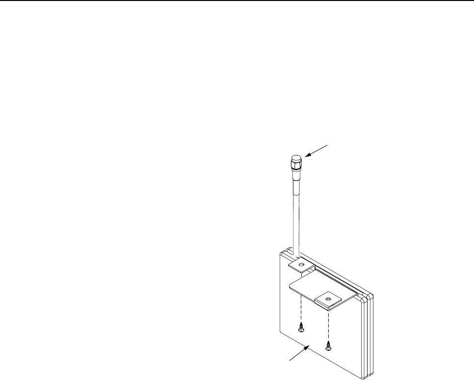
2.5.3 1900 MHz Ceiling-Mount Hallway Antenna
The 1900 MHz ceiling mount hallway antenna is designed to mount in the center of long
corridors. Mount the ceiling-mount hallway antenna as shown in Figure 10 and as described in
the following procedure:
1. At the point where the antenna will be mounted, locate asuspended ceiling tile rail that
is perpendicular to the hallway walls. If the hallway has a hard ceiling, locate apoint
where the antenna may be secured directly to the ceiling.
Note: Whether mounted from atile rail or hard ceiling, the flat sides of the antenna must
be perpendicular to the hallway walls when mounted.
2. Drill a5/8-inch (16 mm) hole in the ceiling at the point where the antenna will be
mounted. If using aceiling tile rail for mounting the antenna, the hole should be next to
the tile rail
3. Insert the antenna cable through the hole in ceiling tile.
4. If using atile rail for mounting the antenna, install the antenna bracket on the tile rail and
proceed to step 9. If mounting the antenna from a hard ceiling, proceed to step 5.
ADCP-75-112 • Issue 2A • June 2001
Page 13
© 2001, ADC Telecommunications, Inc.
5. Hold the antenna in position for mounting on the hard ceiling.
6. Mark the location of the two antenna bracket mounting holes on the hard ceiling.
7. Drill a 1/8-inch (3 mm) hole at each of the two locations marked in step 6.
8. Secure the antenna mounting bracket to the hard ceiling using two #4 screws (must be
provided by installer).
9. Route antenna cable to DRU.
Fig 10-A
SMA CONNECTOR
ORIENT ANTENNA SO FLAT SIDES ARE
PERPENDICULAR WITH HALLWAY WALLS
NOTE: TO COMPLY WITH MAXIMUM
PERMISSIBLE EXPOSURE (MPE) REQUIREMENTS,
ANTENNAS MUST BE INSTALLED TO PROVIDE AT
LEAST 20 CENTIMETERS OF SEPARATION FROM
ALL PERSONS PER FCC 47 CFR PART 2.1091.
Figure 10. 1900 MHz Ceiling-Mount Hallway Antenna Installation
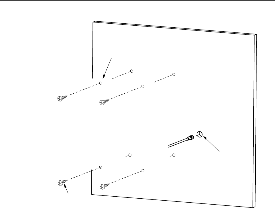
2.5.4 800 MHz Directional Panel Antenna
The 800 MHz directional panel antenna is designed to mount vertically on one side of the
coverage area. Mount the directional panel antenna as shown in Figure 11 and as described in
the following procedure:
1. Drill holes in antenna plastic cover for fasteners (see rear side for hole location).
2. Drill 5/8-inch (16 mm) hole in wall for antenna cable.
3. Insert antenna cable through hole in wall.
4. Place antenna on wall, making sure arrow on rear side of antenna points up.
5. Drill holes in wall for fasteners (installer provided).
6. Secure antenna to wall with fasteners.
7. Route antenna cable to DRU.
ADCP-75-112 • Issue 2A • June 2001
Page 14
© 2001, ADC Telecommunications, Inc.
16246-A
DRILL HOLES THROUGH
PLASTIC COVER ONLY.
SEE REAR SIDE FOR
HOLE LOCATIONS.
USE APPROPRIATE
FASTENERS FOR
WALL SURFACE
NOTE: TO COMPLY WITH MAXIMUM
PERMISSIBLE EXPOSURE (MPE) REQUIREMENTS,
ANTENNAS MUST BE INSTALLED TO PROVIDE AT
LEAST 20 CENTIMETERS OF SEPARATION FROM
ALL PERSONS PER FCC 47 CFR PART 2.1091.
MAKE SURE ARROW ON REAR
SIDE OF ANTENNA IS POINTING
UP WHEN ANTENNA IS MOUNTED
5/8-INCH (16 mm) HOLE
FOR ANTENNA CABLE
Figure 11. 800 MHz Directional Panel Antenna Installation
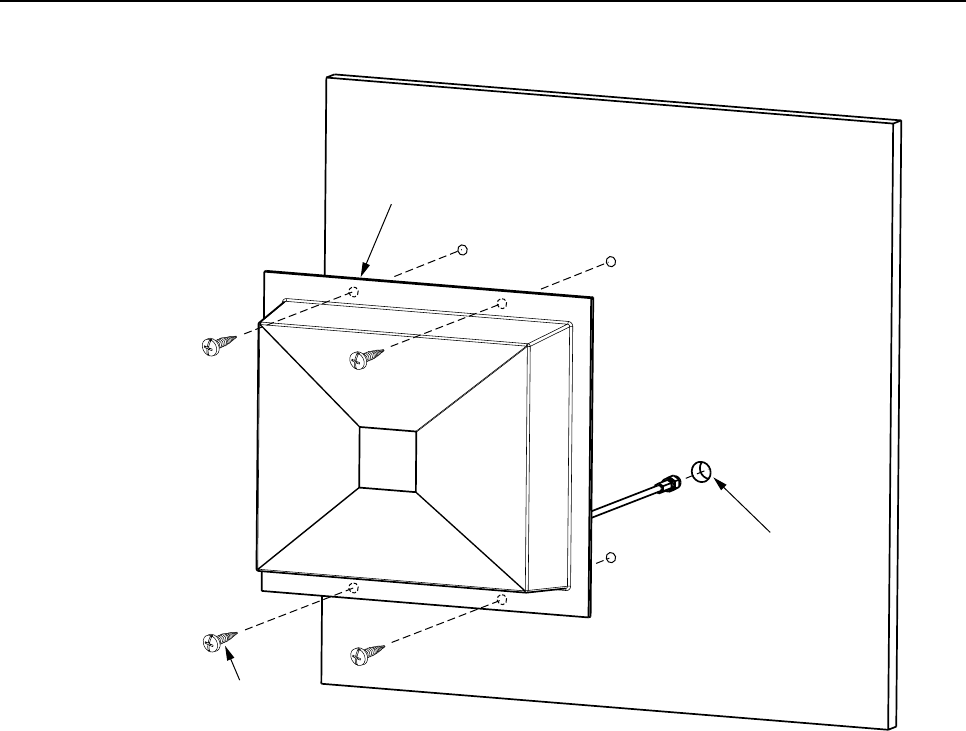
2.5.5 1900 MHz Directional Panel Antenna
The 1900 MHz directional panel antenna is designed to mount vertically on one side of the
coverage area. Mount the directional panel antenna as shown in Figure 12 and as described in
the following procedure:
1. Drill holes in antenna plastic cover for fasteners (see rear side for hole location).
2. Drill 5/8-inch (16 mm) hole in wall for antenna cable.
3. Insert antenna cable through hole in wall.
4. Place antenna on wall, making sure arrow on rear side of antenna points up.
5. Drill holes in wall for fasteners (installer provided).
6. Secure antenna to wall with fasteners.
7. Route antenna cable to DRU.
ADCP-75-112 • Issue 2A • June 2001
Page 15
© 2001, ADC Telecommunications, Inc.
Fig 12-A
DRILL HOLES THROUGH
PLASTIC COVER ONLY.
SEE REAR SIDE FOR
HOLE LOCATIONS.
USE APPROPRIATE
FASTENERS FOR
WALL SURFACE
NOTE: TO COMPLY WITH MAXIMUM
PERMISSIBLE EXPOSURE (MPE) REQUIREMENTS,
ANTENNAS MUST BE INSTALLED TO PROVIDE AT
LEAST 20 CENTIMETERS OF SEPARATION FROM
ALL PERSONS PER FCC 47 CFR PART 2.1091.
MAKE SURE ARROW ON REAR
SIDE OF ANTENNA IS POINTING
UP WHEN ANTENNA IS MOUNTED
5/8-INCH (16 mm) HOLE
FOR ANTENNA CABLE
TO BE COMPLETED
WHEN DRAWING
IS AVAILABLE
Figure 12. 1900 MHz Directional Panel Antenna Installation
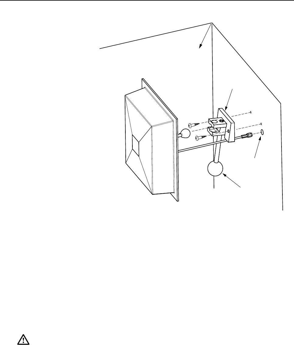
2.5.6 800 MHz 90º Panel Antenna
The 800 MHz 90º panel antenna is designed to mount vertically in the corner of the coverage
area. Mount the 90º panel antenna as shown in Figure 13 and as described in the following
procedure:
1. Loosen base assembly handle until antenna can be separated from base assembly.
2. Place base assembly against wall near corner and drill holes in wall for fasteners
(installer provided).
3. Secure base assembly to wall with fasteners.
4. Drill 5/8-inch (16 mm) hole in wall for antenna cable.
5. Insert antenna cable through hole in wall.
6. Reinstall antenna on base assembly.
7. Direct antenna toward center of coverage area and tighten base assembly handle.
8. Route antenna cable to DRU.
ADCP-75-112 • Issue 2A • June 2001
Page 16
© 2001, ADC Telecommunications, Inc.
16247-A
NOTE: TO COMPLY WITH MAXIMUM
PERMISSIBLE EXPOSURE (MPE) REQUIREMENTS,
ANTENNAS MUST BE INSTALLED TO PROVIDE AT
LEAST 20 CENTIMETERS OF SEPARATION FROM
ALL PERSONS PER FCC 47 CFR PART 2.1091.
MAKE SURE ARROW ON REAR
SIDE OF ANTENNA IS POINTING
UP WHEN ANTENNA IS MOUNTED
5/8-INCH (16 mm) HOLE
FOR ANTENNA CABLE
BASE ASSEMBLY
HANDLE
ORIENT TO CENTER OF
COVERAGE AREA
Figure 13. 800 MHz 90º Panel Antenna Installation
2.6 Antenna Connection
The DRU is equipped with an SMA female connector for connecting the antenna cable. Use
the following procedure to connect the antenna cable to the DRU:
1. Locate the antenna cable that was routed to the DRU from the antenna.
2. Connect the antenna cable to the SMA connector on the DRU as shown in Figure 14 and
using atorque wrench, tighten connector to 5inch-pounds (45 N.cm).
Warning:Over-tightening the SMA connector can break the solder joint between the
connector and the DRU circuit board assembly. Tighten connector to specified torque value.
3. Dress and secure the antenna cable per standard industry practice.
ADCP-75-112 • Issue 2A • June 2001
Page 17
© 2001, ADC Telecommunications, Inc.
ANTENNA
PORT
SMA
CONNECTOR
16451-A
TORQUE WRENCH SET TO
5 INCH-POUNDS (45 N.CM)
Figure 14. DRU Antenna Connection
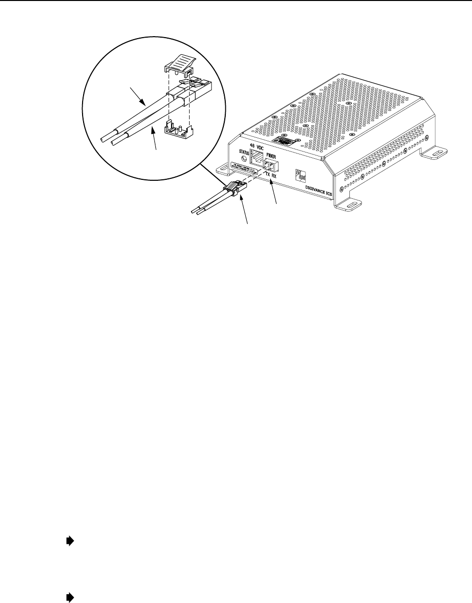
2.7 Optical Connection
The optical interface between the DRU and the DHU or DEU is supported by a small form
factor LC-type optical transceiver which is mounted on the DRU front panel. One side of the
transceiver provides the optical fiber connection for the forward path (downlink) signal. The
other side of the transceiver provides the optical fiber connection for the reverse path (uplink)
signal. Use the following procedure to connect the forward and reverse path optical fibers to
the DRU:
Danger:This equipment uses aClass 1Laser according to FDA/CDRH rules. Laser radiation
can seriously damage the retina of the eye. Do not look into the ends of any optical fiber. Do
not look directly into the optical transceiver of any digital unit or exposure to laser radiation
may result. An optical power meter should be used to verify active fibers. Aprotective cap or
hood MUST be immediately placed over any radiating transceiver or optical fiber connector
to avoid the potential of dangerous amounts of radiation exposure. This practice also prevents
dirt particles from entering the transceiver or connector.
1. Locate the forward and reverse path optical links that were routed to the DRU from the
DHU or DEU.
Note:The procedures for routing the forward and reverse path optical links from the
DHU or DEU to the DRU are covered in either the Digivance ICS Installation and
Operation Manual (ADCP-75-110), which is provided with the DHU, or the Digivance
ICS Digital Expansion Unit Installation Instructions (ADCP-75-111), which is provided
with the DEU.
2. Determine which of the optical cable pairs is designated as the forward path link and
which is designated as the reverse path link.
3. Use the plastic joiner provided with the LC optical connectors to join the DRU forward
and reverse path connectors together as shown in Figure 15. Make sure the forward path
and the reverse path connectors are oriented as shown.
Note:When viewing the DRU optical transceiver from the front, the forward path port is
on the right (RX) and the reverse path port is on the left (TX).
ADCP-75-112 • Issue 2A • June 2001
Page 18
© 2001, ADC Telecommunications, Inc.
OPTICAL
ADAPTER
OPTICAL
CONNECTOR
16452-A
FORWARD PATH (RX)
CONNECTOR
REVERSE PATH (TX)
CONNECTOR
OPTICAL CONNECTOR
ASSEMBLY DETAIL
Figure 15. Optical Port Fiber Optic Cable Connection
4. Remove the dust caps from the optical fiber connectors and from the DRU optical port.
5. Clean each connector (follow connector supplier’s recommendations) and then insert the
optical link connector pair into optical port as shown in Figure 15.
6. Dress and secure the fibers at the DRU per standard industry practice.
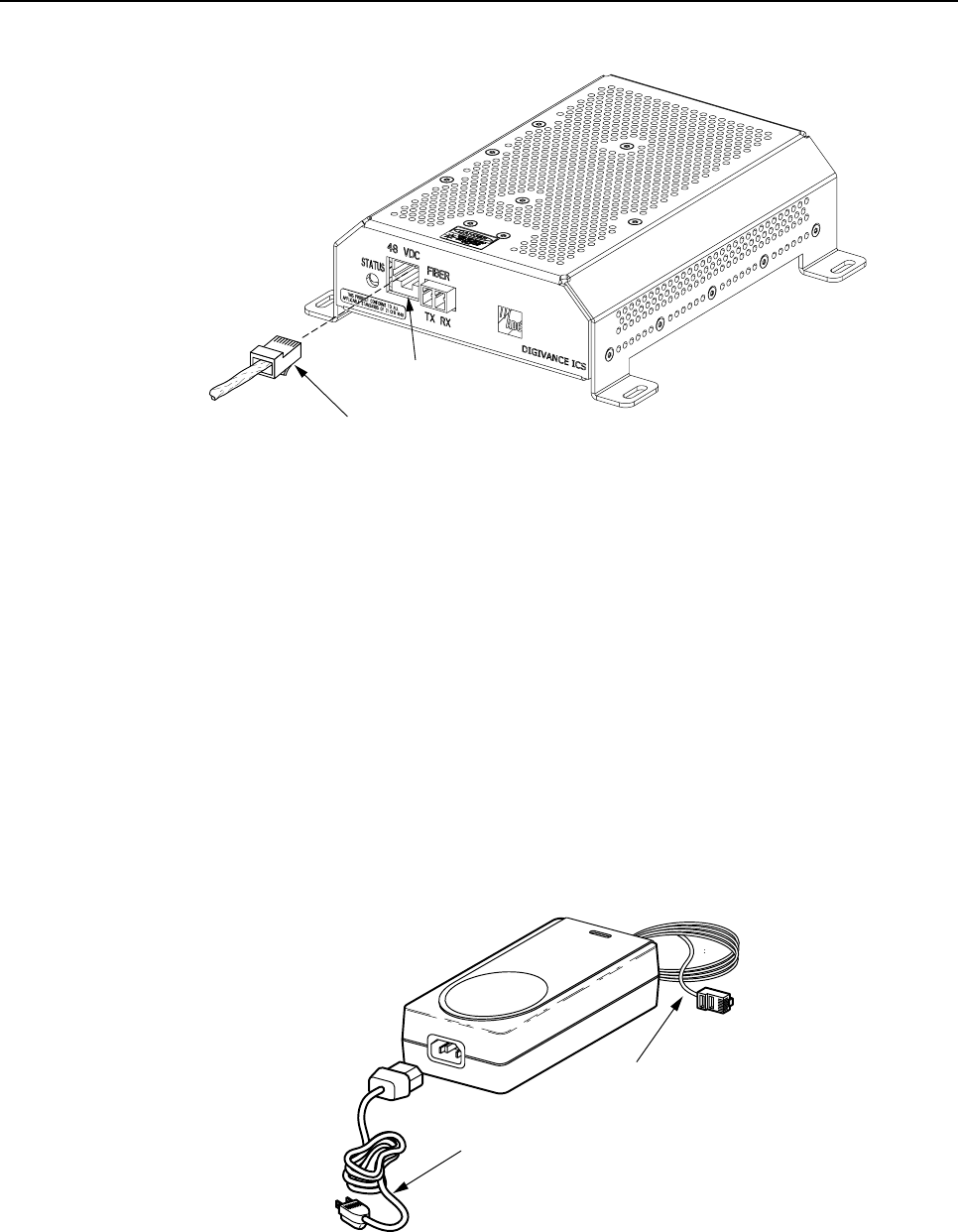
2.8 DC Power Connection
The DC power interface for the DRU is supported by an RJ-45 female connector located on
the DRU front panel. The DRU is powered by nominal 48 Vdc power which may be provided
by the DHU, DEU, or by an AC/DC converter (accessory item). Use whichever of the
following procedures is appropriate for the installation.
2.8.1 Power Provided by the DHU or DEU
Use the following procedure to connect the DC power cable when the DRU is powered by the
DHU or DEU.
1. Locate the DC power cable that was routed to the DRU from the DHU or DEU.
Note:The procedures for routing the DC power cable from the DHU or DEU to the DRU
are covered in either the Digivance ICS Installation and Operation Manual (ADCP-75-
110), which is provided with the DHU, or the Digivance ICS Digital Expansion Unit
Installation Instructions (ADCP-75-111) which is provided with the DEU.
Note: The power cable maximum length is 500 meters (1,641 feet).
2. Connect the DC power cable to the 48 Vdc connector on the DRU as shown in Figure 16.
ADCP-75-112 • Issue 2A • June 2001
Page 19
© 2001, ADC Telecommunications, Inc.
POWER
PORT
POWER
CONNECTOR
16453-A
1
8
Figure 16. DC Power Cable Connection
3. Dress and secure the power cable at the DRU per standard industry practice.
4. When the installation of the DRU is completed, refer to Section 4of the Digivance ICS
Installation and Operation Manual (ADCP-75-110) for the system turn-up and test procedures.
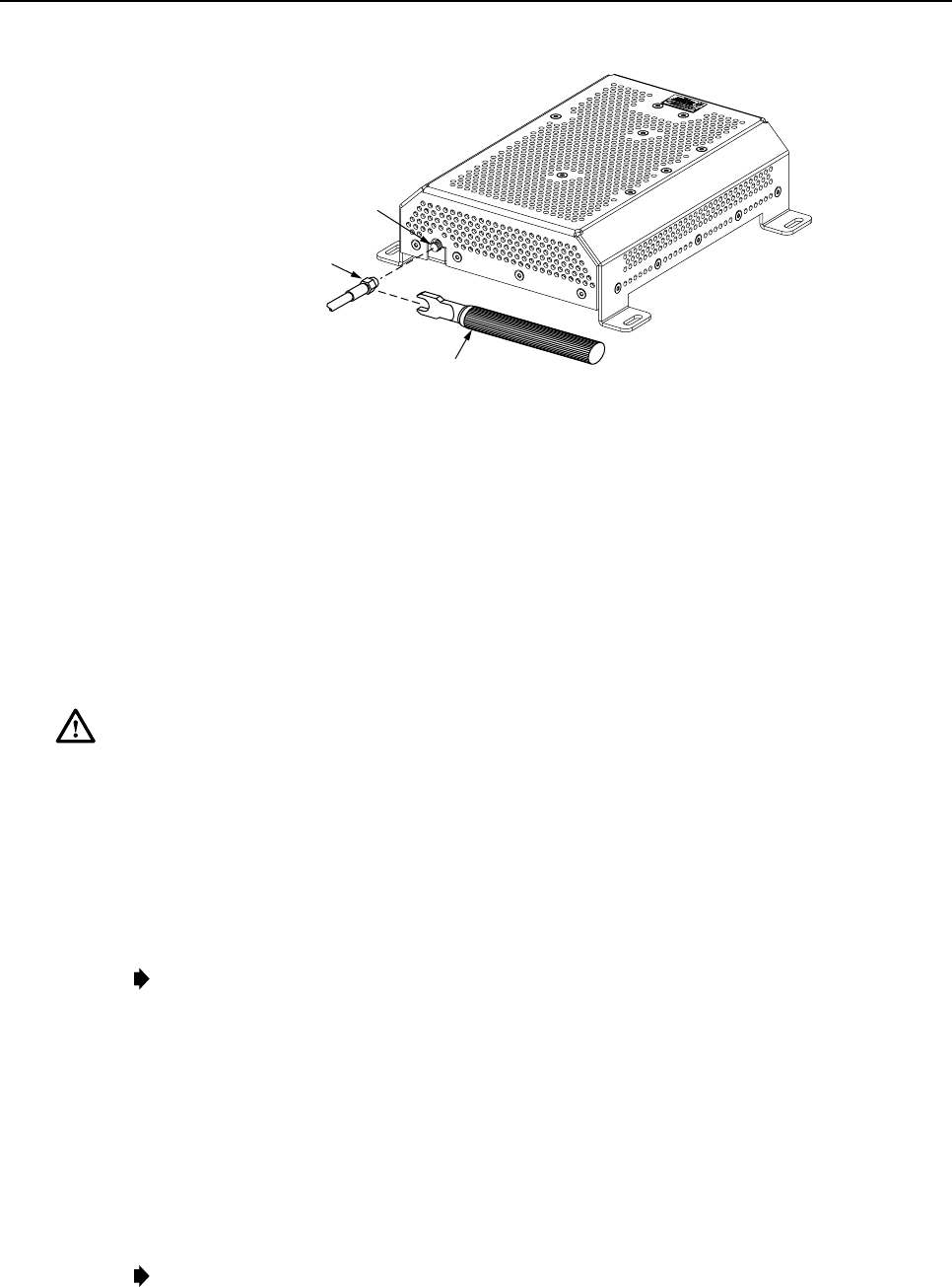
2.8.2 Power Provided by AC/DC Converter
When the DRU is powered by an AC/DC converter, it must be powered by a UL Listed stand
alone Limited Power Supply (LPS) unit with arated output of 48 Vdc at 1.2 Amps. Use the
following procedure to connect the DC and AC power cables when the DRU is powered by an
AC/DC converter.
1. Locate the DC power cable that is attached to the AC/DC converter as shown in Figure 17.
DC POWER CABLE
AC POWER CORD
16454-A
Figure 17. AC/DC Converter Installation

ADCP-75-112 • Issue 2A • June 2001
Page 20
© 2001, ADC Telecommunications, Inc.
2. Connect the DC power cable to the 48 Vdc connector on the DRU (see Figure 16).
3. Locate the AC power cord which is provided with the AC/DC power converter. Use only the
AC power cord provided with the power converter or an equivalent UL/CUL listed and
certified 3-conductor, 18 AWG cord terminated in amolded-on plug cap rated 125 V, 15 A
with amaximum length of 6feet (1.8 m).
Note:The AC/DC converter is intended to be used with a 3-wire grounding type plug
which has a grounding pin. Equipment grounding is to ensure safe operation. Do not
defeat the grounding means. Verify converter is reliably grounded when installed.
4. Connect the receptacle end of the power cord to the AC connector on the AC/DC
converter (see Figure 17).
5. Route the plug end of the power cord to the specified AC outlet (per the system design)
and connect plug to outlet.
Warning:Be sure to check the nameplate rating of the AC/DC converter to avoid overloading
circuits which may cause damage to over-current protection devices and supply wiring.
6. Verify that the STATUS LED on the DRU turns red or blinking red. This indicates that
the DRU is powered but not receiving a forward path optical signal.
Note:Early versions of the DRU use asteady red LED to indicate all major fault
conditions including no optical signal received. Later versions of the DRU use ablinking
red LED to indicate no optical signal received.
7. Dress and secure both power cables per standard industry practice.
8. When the installation of the DRU is completed, refer to Section 4of the Digivance ICS
Installation and Operation Manual (ADCP-75-110) for the system turn-up and test procedures.

ADCP-75-112 • Issue 2A • June 2001
Page 21
3 CUSTOMER INFORMATION AND ASSISTANCE
For customers wanting information on ADC products or help in using them, ADC offers the
services listed below. To obtain any of these services by telephone, first dial the central ADC
telephone number, then dial the extension provided below.
The central number for calls originating in the U.S.A. or Canada is 1-800-366-3891.For calls
originating outside the U.S.A. or Canada, dial country code “1” then dial 952-946-3000.
Sales Assistance
Extension 63000 • Quotation Proposals
• Ordering and Delivery
• General Product Information
Systems Integration
Extension 63000 • Complete Solutions (from Concept to Installation)
• Network Design and Integration Testing
• System Turn-Up and Testing
• Network Monitoring (Upstream or Downstream)
• Power Monitoring and Remote Surveillance
• Service/Maintenance Agreements
• Systems Operation
BCG Technical Assistance
Center
Extension 63475
E-Mail: bcg_tac@adc.com
• Technical Information
• System/Network Configuration
• Product Specification and Application
• Training (Product-Specific)
• Installation and Operation Assistance
• Troubleshooting and Repair
Product Return Department
Extension 63478
E-Mail: repair&return@adc.com
• ADC Return Authorization number and instructions must
be obtained before returning products.
Product information may also be obtained using the ADC web site at www.adc.com or by
writing ADC Telecommunications, Inc., P.O. Box 1101, Minneapolis, MN 55440-1101,
U.S.A.
Contents herein are current as of the date of publication. ADC reserves the right to change the contents without prior notice. In no
event shall ADC be liable for any damages resulting from loss of data, loss of use, or loss of profits and ADC further
disclaims any and all liability for indirect, incidental, special, consequential or other similar damages. This disclaimer of
liability applies to all products, publications and services during and after the warranty period.
This publication may be verified at any time by contacting ADC’s Technical Assistance Center at 1-800-366-3891, extension
63475 (in U.S.A. or Canada) or 952-946-3475 (outside U.S.A. and Canada), or by e-mail to bcg_tac@adc.com..
© 2001, ADC Telecommunications, Inc.
All Rights Reserved
Printed in U.S.A.