ADC Telecommunications DVICS1900-1 Digivance 1900 MHz Indoor Coverage Solution User Manual
ADC Telecommunications Inc Digivance 1900 MHz Indoor Coverage Solution
Contents
- 1. user manual
- 2. usermanual
- 3. dru installation manual
user manual
ADCP-75-110
Issue 2B
July 2001
Digivance™
800/1900 MHz Indoor Coverage Solution
Installation and Operation Manual
DRAFT
1175170 Rev A
FCC ID: F8I-DVICS1900-1

ADCP-75-110 • Issue 2B • July 2001
Page ii
COPYRIGHT
2001, ADC Telecommunications, Inc.
All Rights Reserved
Printed in the U.S.A.
REVISION HISTORY
ISSUE DATE REASON FOR CHANGE
Issue 104/2001 Original
Issue 206/2001 Changes in LED operation, new power cable maximum length recommendations, and update to
specifications table
Issue 2B 07/2001 Updated to cover 1900 MHz version of product
TRADEMARK INFORMATION
ADC and FiberGuide are registered trademarks of ADC Telecommunications, Inc.
Digivance is atrademark of ADC Telecommunications, Inc.
LC is atrademark of Lucent Technologies Inc.
TORX is aregistered trademark of Textron, Inc.
DISCLAIMER OF LIABILITY
Contents herein are current as of the date of publication. ADC reserves the right to change the contents without prior notice.In no
event shall ADC be liable for any damages resulting from loss of data, loss of use, or loss of profits and ADC further
disclaims any and all liability for indirect, incidental, special, consequential or other similar damages. This disclaimer of
liability applies to all products, publications and services during and after the warranty period.
This publication may be verified at any time by contacting ADC’s Technical Assistance Center at 1-800-366-3891, extension
63475 (in U.S.A. or Canada) or 952-946-3475 (outside U.S.A. and Canada), or by e-mail to bcg_tac@adc.com.
ADC Telecommunications, Inc.
P.O. Box 1101, Minneapolis, Minnesota 55440-1101
In U.S.A. and Canada: 1-800-366-3891
Outside U.S.A. and Canada: (952) 938-8080
Fax: (952) 946-3292

ADCP-75-110 • Issue 2B • July 2001
Page iii
2001, ADC Telecommunications, Inc.
TABLE OF CONTENTS
Content Page
1 SYSTEM FUNCTIONAL OVERVIEW AND UNIT DESCRIPTIONS ........................................ 1
1.1 System Functional Overview ....................................................... 1
1.2 Digital Host Unit Description ....................................................... 3
1.3 Digital Remote Unit Description ..................................................... 7
1.4 Digital Expansion Unit Description ................................................... 9
1.5 Terms and Definitions............................................................12
1.6 Specifications .................................................................13
2 INSTALLATION PLANNING AND SYSTEM DESIGN................................................16
2.1 Base Station Interface Requirements..................................................16
2.2 Locating and Mounting Requirements .................................................18
2.3 Powering Requirements ..........................................................19
2.4 Optical Options and Requirements ...................................................20
2.5 Coaxial Cable Requirements .......................................................20
2.6 System Expansion Planning........................................................20
2.7 DRU Antenna Options ............................................................21
2.8 External Alarm System Reporting Requirements ..........................................23
2.9 Frequency Band Selection Requirements (1900 Mhz) ......................................23
2.10 Maintenance Requirements........................................................24
2.11 System Design Recommendations ...................................................24
3 DIGITAL HOST UNIT INSTALLATION PROCEDURE................................................27
3.1 System Plan Review and Pre-Installation Cable Routing .....................................27
3.2 Tools and Materials .............................................................27
3.3 Unpacking and Inspection .........................................................28
3.4 Frequency Band Selection Procedure (1900 Mhz DHU Only) .................................28
3.5 Mounting Procecure ............................................................29
3.6 Chassis Ground Procedure.........................................................32
3.7 Coaxial Cable Connections ........................................................33
3.8 Ports 1–6 Optical Connections ......................................................34
3.9 DC Power Connections ...........................................................35
3.10 Exterma; Alarm System Connections ..................................................37
3.11 AC Power Connections ...........................................................38
3.12 Create As-Built Drawing ..........................................................39
4 SYSTEM OPERATION ..................................................................40
4.1 Tools and Materials .............................................................40
4.2 Turn-Up System and Verify Operation .................................................40
4.3 Correct Installation Problems.......................................................43
4.4 Test System Performance .........................................................45
5 SYSTEM MAINTENANCE PROCEDURES ......................................................46
5.1 Tools and Materials .............................................................46
5.2 Fault Detection and Alarm Reporting..................................................46
(continued)

ADCP-75-110 • Issue 2B • July 2001
Page iv
2001, ADC Telecommunications, Inc.
TABLE OF CONTENTS
Content Page
5.3 Fault Isolation and Troubleshooting.................................................. 47
5.4 Test Procedures ............................................................... 50
5.5 DHU or DEU Fan Replacement...................................................... 54
6 GENERAL INFORMATION ............................................................... 57
6.1 Warranty/Software ............................................................. 57
6.2 Software Service Agreement....................................................... 57
6.3 Repair/Exchange Policy .......................................................... 57
6.4 Repair Charges................................................................ 57
6.5 Replacement/Spare Products ...................................................... 58
6.6 Returned Material.............................................................. 58
6.7 Customer Information and Assistance................................................. 58

ADCP-75-110 • Issue 2B • July 2001
Page v
2001, ADC Telecommunications, Inc.
ABOUT THIS GUIDE
This installation and operation manual provides the following information:
• An overview of the Digivance Indoor Coverage Solution (ICS) and adescription of the
basic system components including the Digital Host Unit (DHU), Digital Expansion Unit
(DEU), and the Digital Remote Unit (DRU).
• System requirements for planning the Digivance ICS installation.
• Procedures for installing the DHU.
• Procedures for operating and maintaining the Digivance ICS.
• Product warranty, repair, return, and replacement information
The procedures for installing the DEU and DRU are provided in other publications which are
referenced in the Related Publications section and at appropriate points within this manual.
RELATED PUBLICATIONS
Listed below are related manuals and their publication numbers. Copies of these publications
can be ordered by contacting the ADC Technical Assistance Center at 1-800-366-3891
(in U.S.A. or Canada) or 952-946-3000, extension 63475 (outside U.S.A. and Canada).
Title/Description ADCP Number
Digivance ICS Digital Expansion Unit Installation Instructions 75-111
Provides adescription of the DEU and procedures for installing the DEU.
Digivance ICS Digital Remote Unit Installation Instructions 75-112
Provides adescription of the DRU and procedures for installing the DRU.
Digivance ICS Local Interface Unit User Manual 75-113
Provides adescription of the LIU and procedures for installing the LIU.
Digivance ICS Remote Interface Unit User Manual 75-114
Provides adescription of the RIU and procedures for installing the RIU.

ADCP-75-110 • Issue 2B • July 2001
Page vi
2001, ADC Telecommunications, Inc.
ADMONISHMENTS
Important safety admonishments are used throughout this manual to warn of possible hazards
to persons or equipment. An admonishment identifies apossible hazard and then explains
what may happen if the hazard is not avoided. The admonishments —in the form of Dangers,
Warnings, and Cautions —must be followed at all times. These warnings are flagged by use
of the triangular alert icon (seen below), and are listed in descending order of severity of injury
or damage and likelihood of occurrence.
Danger:Danger is used to indicate the presence of a hazard that will cause severe personal
injury, death, or substantial property damage if the hazard is not avoided.
Warning:Warning is used to indicate the presence of a hazard that can cause severe
personal injury, death, or substantial property damage if the hazard is not avoided.
Caution:Caution is used to indicate the presence of a hazard that will or can cause minor
personal injury or property damage if the hazard is not avoided.
GENERAL SAFETY PRECAUTIONS
The following general admonishments apply throughout the procedures in this manual.
Warning:Wet conditions increase the potential for receiving an electrical shock when
installing or using electrically-powered equipment. To prevent electrical shock, never install
or use electrical equipment in awet location or during alightning storm.
Warning:The DRU is powered by 48 VDC power which is supplied over customer-provided
wiring. To prevent electrical shock when installing or modifying the DRU power wiring,
disconnect the wiring at the power source before working with uninsulated wires or terminals.
Danger:This equipment uses aClass 1Laser according to FDA/CDRH rules. Laser radiation
can seriously damage the retina of the eye. Do not look into the ends of any optical fiber. Do
not look directly into the optical adapters of any digital unit or exposure to laser radiation
may result. An optical power meter should be used to verify active fibers. Aprotective cap or
hood MUST be immediately placed over any radiating adapter or optical fiber connector to
avoid the potential of dangerous amounts of radiation exposure. This practice also prevents
dirt particles from entering the adapter or connector
Danger:Do not look into the ends of any optical fiber. Exposure to laser radiation may result. Do
not assume laser power is turned-off or the fiber is disconnected at the other end.
Danger:Always allow sufficient fiber length to permit routing without severe bends. Fibers
may be permanently damaged if bent/curved to aradius of less than 2inches (50 mm).

ADCP-75-110 • Issue 2B • July 2001
Page vii
2001, ADC Telecommunications, Inc.
STANDARDS CERTIFICATION
FCC:This equipment complies with the applicable sections of Title 47 CFR Parts 15, 22, 24,
and 90.
UL/CUL:This equipment complies with UL and CUL 1950 Standard for Safety for
Information Technology Equipment, Including Electrical Business Equipment.
FDA/CDRH:This equipment uses aClass 1LASER according to FDA/CDRH Rules. This
product conforms to all applicable standards of 21 CFR Part 1040.
LIST OF ACRONYMS AND ABBREVIATIONS
The acronyms and abbreviations used in this manual are detailed in the following list:
AAmperes
AC Alternating Current
AGC Automatic Gain Control
AMPS Advanced Mobile Phone Service
CDMA Code Division Multiple Access
CDRH Center for Devices and Radiological Health
CUL Canadian Underwriters Laboratories
DAS Distributed Antenna System
DC Direct Current
DEU Digital Expansion Unit
DHU Digital Host Unit
DRU Digital Remote Unit
EIA Electronic Industries Association
ERP Effective Radiated Power
ESD Electrostatic Discharge
FCC Federal Communications Commission
FDA Food and Drug Administration
ICS Indoor Coverage Solution
LIU Local Interface Unit
NOC Network Operations Center
PWR Power
RIU Remote Interface Unit
RF Radio Frequency
RSSI Received Signal Strength Indication
RX Receive or Receiver
TDMA Time Division Multiple Access
TX Transmit or Transmitter
UL Underwriters Laboratories
UPS Uninterruptible Power Supply
VVolts
VAC Volts Alternating Current
VDC Volts Direct Current
WECO Western Electric Company

ADCP-75-110 • Issue 2B • July 2001
Page 1
©2001, ADC Telecommunications, Inc.
1 SYSTEM FUNCTIONAL OVERVIEW AND UNIT DESCRIPTION
This section provides an overview of the Digivance Indoor Coverage Solution (ICS), a
description of the functions and features provided by the units that comprise the system, a
listing of terms used and their definition, and atable of specifications.
1.1 System Functional Overview
The Digivance ICS is adigitally distributed antenna system that provides in-building coverage
for analog (AMPS) or digital (TDMA or CDMA) cellular phone systems operating within the
800 and 1900 MHz frequency bands. Large buildings typically interfere with the transmission
or reception of cellular phone system signals by imposing high attenuation losses on RF
signals. The Digivance ICS is designed to overcome the attenuation losses that make cellular
communications within buildings or structures difficult or impossible. With the Digivance
ICS, cellular phone RF signals can be distributed to the interior areas of any building or
structure to eliminate dead spots and improve reception.
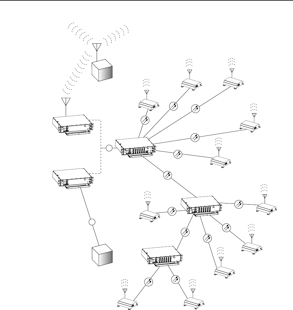
1.1.1 Basic System Components
The basic components of the Digivance ICS and their functions are shown in Figure 1. The
basic system consists of the Digital Host Unit (DHU), Digital Remote Unit (DRU), and when
additional capacity or longer fiber runs are required, the Digital Expansion Unit (DEU). In
addition, two accessory items, the Local Interface Unit (LIU) and the Remote Interface Unit
(RIU) may be used as needed to interface the DHU with the cellular system Base Transceiver
Station (BTS).
1.1.2 Interface With BTS
The DHU interfaces, either locally or remotely, with the BTS. As referenced in this
publication, the BTS could be either amicrocell or a cell site base station. When the BTS
(microcell) is co-located with the DHU, alocal interface over coaxial cable is possible. An
interface device, such as the LIU, may be required to provide the proper input and output RF
signal levels between the BTS and the DHU. When the BTS (cell site base station) is not co-
located with the DHU, aremote interface using a donor antenna is required. An interface
device such as the RIU is required to provide the proper input and output RF signal levels
between the donor antenna and the DHU.
The DHU interfaces, as described in the preceding paragraph, with the BTS. In the forward
path, the DHU receives RF signals from the BTS. The DHU digitizes the RF signals and then
converts them to digital optical signals for transport to the DEUs and DRUs. In the reverse
path, the DHU receives digital optical signals from the DRUs and DEUs. The DHU converts
the optical signals back to the original RF signal format for transmission to the BTS.
ADCP-75-110 • Issue 2B • July 2001
Page 2
©2001, ADC Telecommunications, Inc.
DRU
DRU
DRU
DRU
DRU
DRU
DRU
DRU
DRU
DRU
DRU
DEU
DEU
DHU
RIU
LIU
REMOTE
BTS
LOCAL
BTS
RF
16417-A
RF
Figure 1. System Overview Functional Block Diagram
1.1.3 Interface With Cellular Phones
The DRUs interface with the cellular phones. In the reverse path, the DRU receives RF signals
from each cellular phone. The DRU digitizes the RF signals and then converts them to digital
optical signals for transport to the DHU. In the forward path, the DRU receives digital optical
signals from the DHU. The DRU converts the optical signals back to the original RF signal
format for transmission to the cellular phones. Asmall antenna is connected to the DRU to
transmit and receive RF signals from the cellular phones.

ADCP-75-110 • Issue 2B • July 2001
Page 3
©2001, ADC Telecommunications, Inc.
1.1.4 Digital Fiber Optic Transport
The DHU is connected to each DRU unit over a pair of multi-mode fiber optic links. One link
is used to transport the forward path optical signal. The other link is used to transport the
reverse path optical signal. Because the optical signal is digital, no adjustments to the optical
signal level are required at the DRU or the DHU regardless of the length of the optical link.
Either 50 or 62.5 micron core multi-mode fiber optic cable may be used for the optical link. If
50 micron cable is used, the optical link may be up to 750 meters in length. If 62.5 micron
core cable is used, the optical link may be up to 500 meters in length. The fiber optic links are
terminated with LC connectors.
1.1.5 Capacity for Expansion and Extended Runs
The DEU enables 6-way expansion of any optical port. This makes it possible to add more
DRUs without having to install additional DHUs. Each DHU is equipped with six optical
ports. If more than six DRUs are required by the application, aDEU may be connected to one
of the optical ports at the DHU which expands that port to six ports. If still more optical ports
are required, then asecond DEU may be connected to the DHU or a second DEU may be
connected to the first DEU. The ability to cascade DEU’s in parallel or in series provides
unlimited flexibility. It is physically possible to connect an unlimited number DRUs to the
DHU through the installation of DEUs. The maximum number of DRUs that can connected to
the DHU is limited only by the cumulative noise effect caused by antenna combining.
1.1.6 Power Requirements
The DHU, DEU, LIU, and RIU are each powered by 120–240 Vac (50–60 Hz) power which is
supplied through astandard three-conductor AC power cord. The DRU is powered by 34–48
Vdc which is supplied by either the DHU, DEU, or an ac/dc wall-mount style converter. When
the DRU is powered by the DHU or DEU, the power is fed through acategory 3 or 5 cable
terminated with male RJ-45 connectors.
1.1.7 Fault Detection and Alarm Reporting
LED indicators are provided on the front panel of the various units to indicate if the system is
normal or if afault is detected. In addition, normally open and normally closed alarm contacts
(for both major and minor alarms) are provided at the DHU for connection to acustomer
provided external alarm system. This could bealocal system or automatic call-out system.
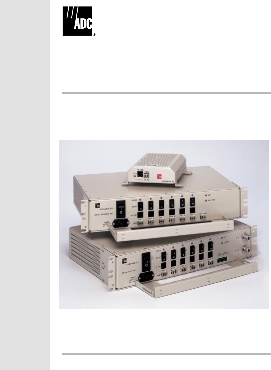
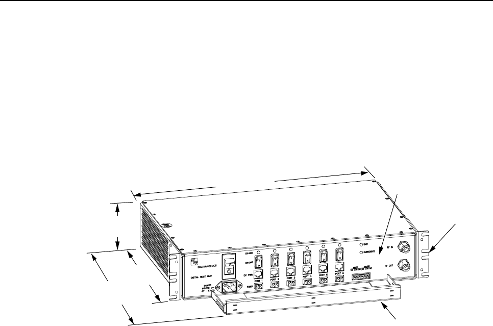
1.2 Digital Host Unit Description
The DHU, shown in Figure 2, serves as the BTS servicing unit for the Digivance ICS. The
DHU provides the following basic functions:
• RF inputs and outputs
• Optical interface to the DRUs or DEUs
• Digitizing of the cellular forward path RF signal
ADCP-75-110 • Issue 2B • July 2001
Page 4
©2001, ADC Telecommunications, Inc.
• Distribution of the digitized forward path RF signals into six digitized optical signals
• Conversion of up to six reverse path digitized optical signals to six digitized RF signals
• Combining of the six digitized RF signals into asingle composite digitized RF signal
• Conversion of the combined digitized RF signal to acomposite RF signal
• DC power for powering the DRUs
• Relay contact closures to provide alarm information to an external alarm system
17.2 INCHES
(437 mm)
3.5 INCHES
(89 mm)
11.4 INCHES
(290 mm)
15.3 INCHES
(389 mm)
FRONT PANEL
CABLE MANAGEMENT
TRAY
MOUNTING
BRACKET
(BOTH SIDES)
16418-A
Figure 2. Digital Host Unit
1.2.1 Primary Components
The DHU consists of two electronic circuit board assemblies, apower supply assembly, and a
fan assembly that are mounted within apowder-coated sheet metal enclosure. The metal
enclosure provides amounting point for the electronic assemblies, serves as aheat sink, and
controls RF emissions. Except for the fan units, the electronic circuit board assemblies are not
user replaceable. The DHU is designed for use within anon-condensing indoor environment
such as inside awiring closet or cabinet. All controls, connectors, and indicators are mounted
on the DHU front panel for convenient access. Cable management functions for the power and
fiber optic cables are provided by a cable management tray that extends outward from the
DHU front panel.
1.2.2 Mounting
The DHU may be used in both rack-mount and wall-mount applications. For rack mount
applications, apair of reversible mounting brackets is provided that allow the DHU to be
mounted in either a19-inch or 23-inch EIA or WECO equipment rack. When rack-mounted,
the front panel of the DHU is flush with the front of the rack. The cable management tray
extends 3.9 inches (99 mm) beyond the front panel. For wall-mount applications, apair of
holes is provided in the cable management tray which allow the DHU to be mounted on any
flat vertical surface. The DHU should be oriented with the front panel facing upward when
wall-mounted. Fasteners are provided for rack-mount applications.

ADCP-75-110 • Issue 2B • July 2001
Page 5
©2001, ADC Telecommunications, Inc.
1.2.3 Fault Detection and Alarm Reporting
The DHU is designed to detect internal circuitry faults and optical port faults. Various front
panel Light Emitting Diode (LED) indicators turn from green to red or yellow if afault is
detected or an optical input is lost. Aset of alarm contacts (normally open and normally
closed) are also provided for reporting an alarm to an external alarm system when afault is
detected. Both major alarm (all fault conditions except high temperature) and minor alarm
(high temperature fault condition) contacts are provided.
1.2.4 RF Signal Connections
The RF signal connections between the DHU and the BTS are supported through two type N
female connectors. One connector is used for coaxial cable connection of the forward path RF
signal. The other connector is used for coaxial cable connection of the reverse path RF signal. In
most installations, the DHU will not connect directly to the BTS but will be connected to an
interface device such as the RIU or the LIU. Additional information concerning the DHU to BTS
interface is provided in the Digivance ICS Remote Interface Unit User Manual (ADCP-75-113) and
in the Digivance ICS Local Interface Unit User Manual (ADCP-75-114).
The DHU requires acomposite forward path RF signal level of –20 dBm or lower. An
overdrive limiter protects the system against excessive inputs but does not function during
normal operation. The DHU does not have Automatic Gain Control (AGC).
1.2.5 Optical and Electrical Interface Connections
Operation of the DRUs and DEUs is supported by six optical and six electrical ports. Each optical
and electrical interface connection includes astatus LED, asmall form factor LC type optical
transceiver, an RJ-45 DC power jack, and aport enable/disable switch. An optical port may be
connected to aDRU, aDEU, or not used. An electrical port may be connected to aDRU or not
used. Unused ports require no connections at all and are disabled via the corresponding port
enable/disable switch. When disabled, the port LED is off, the alarm reporting function is disabled,
the laser is off, and the DC power is off. Enabling the enable/disable switch activates all functions.
1.2.6 Powering
The DHU is powered by 120–240 Vac (50–60 Hz) power which is supplied through astandard
three-conductor AC power cord. The power cord is provided with the DHU and is 98 inches
(2.5 meters )long. Aresetable circuit breaker/On-Off switch is provided at the unit front
panel. The switch applies power to the DHU internal power supply.
1.2.7 Cooling
Continuous air flow for cooling is provided by dual fans mounted on the right side of the housing.
Aminimum of 3inches (76 mm) of clearance space must be provided on both the left and right
sides of the DHU for air intake and exhaust. An alarm is provided that indicates if ahigh
temperature condition (>50º C/122º F) occurs. The fans may be field-replaced if either fan fails.
1.2.8 User Interface
The DHU user interface consists of the various connectors, switches, terminals, and LEDs that
are provided on the DHU front panel. The DHU user interface points are indicated in Figure 3
and described in Table 1.
ADCP-75-110 • Issue 2B • July 2001
Page 6
©2001, ADC Telecommunications, Inc.
(1) AC POWER CORD
CONNECTOR
(2) AC POWER
ON/OFF SWITCH (3) OPTICAL PORT
LED INDICATOR
(6 PLACES)
(4) OPT/ELEC PORT
ENABLE/DISABLE
SWITCH (6 PLACES)
(5) ELECTRICAL PORT
DC POWER JACK
(6 PLACES)
(6) OPTICAL PORT
OPTICAL ADAPTERS
TX-LEFT - RX-RIGHT
(6 PLACES)
(7) UNIT LED
INDICATOR (10) RF INPUT
CONNECTOR
(8) OVERDRIVE
LED
INDICATOR
(9) ALARM
TERMINAL
STRIP
(11) RF OUTPUT
CONNECTOR
16419-A
NOTE: SHOWN WITHOUT
CABLE MANAGEMENT TRAY
Figure 3. Digital Host Unit User Interface
Table 1. Digital Host Unit User Interface
REF
No. USER INTERFACE
DESIGNATION
DEVICE FUNCTIONAL
DESCRIPTION
1POWER 3-wire AC power
cord connector Used for connecting the AC power cord.
2I/O I/O rocker switch/
circuit breaker Provides AC power On/Off control and
AC power over current protection.
3OK/NOK (Ports 1–6) Multi-colored LED
(Red/Green/Yellow) Indicates if the DRU or remote DEU connected
to the optical port is normal or faulty or if the
reverse path optical input from the DRU or
remote DEU is normal or lost. (see Note)
4ON/OFF (Ports 1–6) I/O rocker switch Enables or disables corresponding
electrical and optical ports.
5DC PWR (Ports 1–6) RJ-45 jack (female) Used for connecting aDRU cat 3or 5power
cable to the designated DC power jack.
6FIBER (Ports 1–6) Small form factor
LC-type optical
transceiver
Used for connecting each DEU or DRU
forward path and reverse path optical link
to the designated optical port.
7UNIT Multi-colored LED
(Red/Green/Yellow) Indicates if the DHU is normal or faulty.
(see Note)
8OVERDRIVE Multi-colored LED
(Red/Green/Yellow) Indicates when the forward path RF input
power is overdriving the DHU digitizing
circuitry. (see Note)
9MAJOR MINOR Screw-type terminal
connector
(14–26 AWG)
Used for connecting an external alarm
system to the DHU. Includes normally open
(NO), normally closed (NC), and common
(COM) wiring connections.
10 RF IN N-type female RF
coaxial connector Used for connecting the forward path RF
coaxial cable to the DHU.
11 RF OUT N-type female RF
coaxial connector Used for connecting the reverse path RF
coaxial cable to the DHU.
Note: Adetailed description of LED operation is provided in Section 4.
ADCP-75-110 • Issue 2B • July 2001
Page 7
©2001, ADC Telecommunications, Inc.
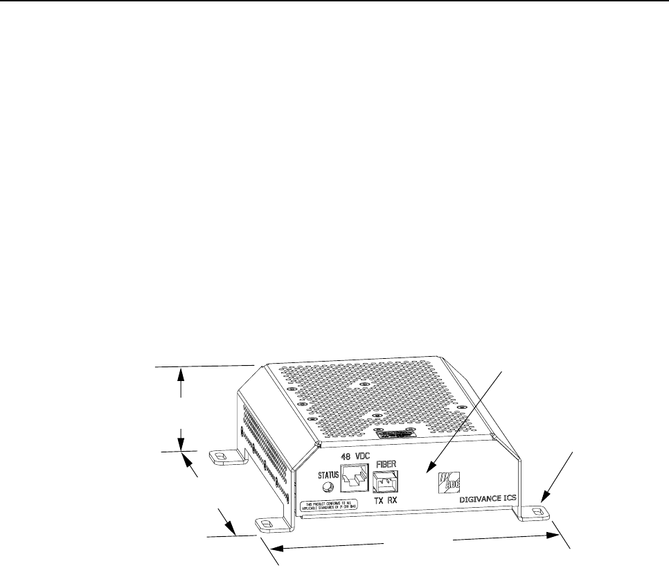
1.3 Digital Remote Unit Description
The DRU, shown in Figure 4, serves as the cellular user servicing unit for the Digivance ICS.
The DRU provides the following basic functions:
• RF interface to the cellular users via an external antenna
• Optical interface to the DHU or DEU
• Conversion of the forward path digitized optical signal to adigitized RF signal
• Conversion of the digitized forward path RF signal to the original cellular RF signal
• Digitizing of the cellular reverse path RF signal
• Conversion of the digitized reverse path RF signal to adigital optical signal output
• Transports alarm status via optical link
FRONT PANEL
MOUNTING FOOT
(EACH CORNER)
7.0 INCHES
(178 mm)
7.3 INCHES
(185 mm)
2.1 INCHES
(53 mm)
16420-A
Figure 4. Digital Remote Unit
1.3.1 Primary components
The DRU consists of an electronic circuit board assembly that is mounted within apowder-
coated sheet metal enclosure. The metal enclosure provides amounting point for the electronic
assembly, serves as aheat sink, and controls RF emissions. The electronic circuit board
assembly is not user replaceable. The DRU is designed for use within anon-condensing
indoor environment such as inside abuilding. All controls, connectors, and indicators (except
the SMA antenna connector) are mounted on the DRU front panel for convenient access.
1.3.2 Mounting
The DRU is equipped with four integral mounting feet that allow it to be mounted on any flat
horizontal or vertical surface. Atypical location for mounting the DRU would be above
ceiling tiles where the optical fiber and power cables can be concealed or on a wall. Slots are
provided in the mounting feet for securing the DRU to the mounting surface.

ADCP-75-110 • Issue 2B • July 2001
Page 8
©2001, ADC Telecommunications, Inc.
1.3.3 Fault Detection
The DRU is designed to detect internal circuitry faults or loss of system inputs. A front panel
LED indicator turns from green to red when afault condition is detected or when the optical
input is lost. The DRU sends the fault information to the DHU or DEU over the fiber optic
link. Acorresponding port LED at the DHU or DEU turns from green to red when the DRU
reports afault.
1.3.4 RF Signal Interface
The RF signal interface between the DRU and the cellular users is provided through an
external antenna connected to afemale SMA connector. The antenna must be ordered
separately. Several types of antennas with various RF propagations are available. Non-ADC
antennas may also be used with the DRU to meet various application requirements.
1.3.5 Optical Port
The DRU is equipped with asmall form factor LC type optical transceiver that provides a
point for connecting the optical link cables. Depending on the application requirements, the
optical port may be connected to either aDHU or a DEU.
1.3.6 Powering
The DRU is equipped with afemale RJ-45 jack that provides apoint for connecting aDC
power cable. The DRU is powered by 34–48 Vdc power which is supplied through the RJ-45
connector. Power to the DRU may be supplied by the DHU, DEU, or by a 120 Vac to 48 Vdc
power converter (available separately as an accessory item) plugged into a properly grounded
120 Vac outlet. The ac/dc converter is aUL Listed stand alone Limited Power Supply (LPS)
unit with arated output of 48 Vdc at 1.2 Amps. When powered by the DHU or DEU, a
category 3 or 5 twisted-pair cable terminated with RJ-45 connectors is required.
1.3.7 Cooling
The DRU is cooled by natural convection air flow. The DRU mounting feet are designed to provide
clearance under the unit so that air can enter the DRU enclosure from the bottom and exit through
the top. Aminimum clearance of 3inches (76 mm) must be provided on all sides of the DRU
(except the bottom) to ensure there is adequate air circulation for cooling. In addition, at least one
surface of the DRU installation area must be open to the interior of the building.
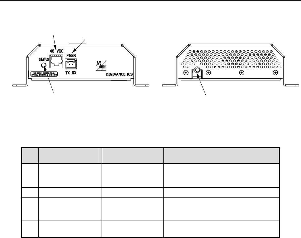
1.3.8 User Interface
The DRU user interface consists of the connectors and the LED that are provided on the DRU
front and rear panels. The DRU user interface points are indicated in Figure 5 and described in
Table 2.
ADCP-75-110 • Issue 2B • July 2001
Page 9
©2001, ADC Telecommunications, Inc.
16421-A
REAR VIEWFRONT VIEW
(4) ANTENNA CONNECTOR
(1) STATUS LED
(2) 48 VDC POWER
CONNECTOR (3) FIBER LINK
OPTICAL ADAPTERS
TX-LEFT - RX-RIGHT
Figure 5. Digital Remote Unit User Interface
Table 2. Digital Remote Unit User Interface
REF
No. USER INTERFACE
DESIGNATION
DEVICE FUNCTIONAL
DESCRIPTION
1STATUS Multi-colored LED
(Red/Green/Yellow) Indicates if the status of the DRU is
normal or faulty or if the forward path
optical input is normal or lost. (see Note)
2 48 VDC RJ-45 jack (female) Used for connecting a DC power cable.
3FIBER
TX RX Small form factor
LC-type optical
transceiver
Used for connecting the forward path and
reverse path optical links.
4 – SMA-type coaxial
connector (female) Used for connecting the antenna coaxial
cable lead.
Note: Adetailed description of LED operation is provided in Section 4.
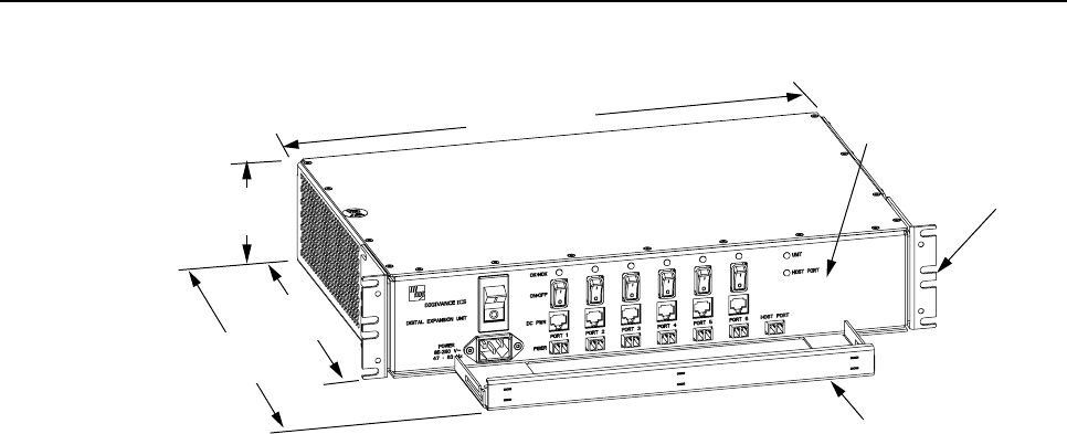
1.4 Digital Expansion Unit Description
The DEU, shown in Figure 6, serves as aservice expansion unit and line extender for the
Digivance ICS. The DEU provides the following basic functions:
• Optical interface to the DHU and up to six DRUs or DEUs
• Conversion of the forward path digitized optical signal to an electrical bit stream
• Splitting of the electrical bit stream into six separate bit streams
• Conversion of the six forward path electrical bit streams into six digital optical signals
• Conversion of up to six reverse path digital optical signals into six serial bit streams
• Combining of the six reverse path serial bit streams into asingle digital composite signal
• Conversion of the single digital composite signal to adigital optical signal
• DC power for powering the DRUs
• Alarm transport via the optical links
ADCP-75-110 • Issue 2B • July 2001
Page 10
©2001, ADC Telecommunications, Inc.
FRONT PANEL
CABLE MANAGEMENT
TRAY
MOUNTING
BRACKET
(BOTH SIDES)
16422-A
3.5 INCHES
(89 mm)
11.4 INCHES
(290 mm)
15.3 INCHES
(389 mm)
17.2 INCHES
(437 mm)
Figure 6. Digital Expansion Unit
1.4.1 Primary Components
The DEU consists of two electronic circuit board assemblies and apower supply that are
mounted within apowder-coated sheet metal enclosure. The metal enclosure provides a
mounting point for the electronic assemblies and serves as aheat sink. Except for the fan
units, the electronic circuit board assemblies are not user replaceable. The DEU is designed for
use within anon-condensing indoor environment such as inside awiring closet or cabinet. All
controls, connectors, and indicators are mounted on the DEU front panel for convenient
access. Cable management functions for the power and fiber optic cables are provided by a
cable management tray that extends outward from the DEU front panel.
1.4.2 Mounting
The DEU may be used in both rack-mount and wall-mount applications. For rack mount
applications, apair of reversible mounting brackets is provided that allow the DEU to be
mounted in either a19-inch or 23-inch EIA or WECO equipment rack. When rack-mounted,
the front panel of the DEU is flush with the front of the rack. The cable management tray
extends 3.9 inches (99 mm) beyond the front panel. For wall-mount applications, apair of
holes is provided in the cable management tray which allow the DEU to be mounted on any
flat vertical surface. The DEU should be oriented with the front panel facing upward when
wall-mounted. Fasteners are provided for rack-mount applications.
1.4.3 Fault Detection
The DEU is designed to detect internal circuitry faults or loss of system inputs. Various front
panel Light Emitting Diode (LED) indicators turn from green to red or yellow when afault is
detected or when an optical input is lost. The DEU transports the fault information to the DHU
or supporting DEU over the fiber optic link. Acorresponding port LED at the DHU or DEU
turns from green to red when the DEU reports afault.
ADCP-75-110 • Issue 2B • July 2001
Page 11
©2001, ADC Telecommunications, Inc.
1.4.4 Optical and Electrical Interface Connections
Operation of the DRUs and DEUs is supported by six optical and six electrical ports. Each
optical and electrical interface connection includes astatus LED, asmall form factor LC type
optical transceiver, an RJ-45 DC power jack, and a port enable/disable switch. An optical port
may be connected to aDRU, aDEU, or not used. An electrical port may be connected to a
DRU or not used. Unused ports require no connections at all and are disabled via the
corresponding port enable/disable switch. When disabled, the port LED is off, the alarm
reporting function is disabled, the laser is off, and the DC power is off. Enabling the
enable/disable switch activates all functions. The DEU also provides one optical port
designated the host port for the optical interface with the DHU or a supporting DEU.
1.4.5 Powering
The DEU is powered by 120–240 Vac (50–60 Hz) power which is supplied though astandard
three-conductor AC power cord. The power cord is provided with the DEU and is 98 inches
(2.5 meters) long. Areset able circuit breaker/On-Off switch is provided at the unit front
panel. The switch applies power to the DEU internal power supply.
1.4.6 Cooling
Continuous air flow for cooling is provided by dual fans mounted on the right side of the sheet
metal housing. Aminimum of 3 inches (76 mm) of clearance space must be provided on both
the left and right sides of the DEU for air intake and exhaust. An alarm is provided that
indicates if ahigh temperature condition (>50º C/122º F) occurs. The fans may be field-
replaced if either unit fails.
1.4.7 User Interface
The DEU user interface consists of the various connectors, switches, and LEDs that are
provided on the DEU front panel. The DEU user interface points are indicated in Figure 7 and
described in Table 3.
16423-A
(2) AC POWER
ON/OFF SWITCH (3) OPTICAL PORT
LED INDICATOR
(6 PLACES)
(4) OPT/ELEC PORT
ENABLE/DISABLE
SWITCH (6 PLACES)
(8) UNIT LED
INDICATOR
(1) AC POWER CORD
CONNECTOR (5) ELECTRICAL PORT
DC POWER JACK
(6 PLACES)
(6) OPTICAL PORT
OPTICAL ADAPTERS
TX-LEFT - RX-RIGHT
(6 PLACES)
(9) HOST PORT
LED
INDICATOR
(7) HOST PORT
OPTICAL ADAPTERS
TX-LEFT - RX-RIGHT
NOTE: SHOWN WITHOUT
CABLE MANAGEMENT TRAY
Figure 7. Digital Expansion Unit User Interface

ADCP-75-110 • Issue 2B • July 2001
Page 12
©2001, ADC Telecommunications, Inc.
Table 3. Digital Expansion Unit User Interface
REF
No. USER INTERFACE
DESIGNATION
DEVICE FUNCTIONAL
DESCRIPTION
1POWER 3-wire AC power
cord connector Used for connecting the AC power cord.
2I/O I/O rocker switch/
circuit breaker Provides AC power On/Off control and
AC power over current protection.
3OK/NOK (Ports 1–6) Multi-colored LED
(Red/Green/Yellow) Indicates if the DRU or remote DEU
connected to the optical port is normal or
faulty or if the reverse path optical input
from the DRU or remote DEU is normal
or lost. (see Note)
4ON/OFF (Ports 1–6) I/O rocker switch Enables or disables corresponding
electrical and optical ports.
5DC PWR (Ports 1–6) RJ-45 jack (female) Used for connecting aDRU cat 3or 5power
cable to the designated DC power jack.
6FIBER (Ports 1–6) Small form factor
LC-type optical
transceiver
Used for connecting each DRU or remote
DEU forward path and reverse path optical
link to the designated optical port.
7HOST PORT Small form factor
LC-type optical
transceiver
Used for connecting the DHU or supporting
DEU forward path and reverse path optical link.
8UNIT Multi-colored LED
(Red/Green/Yellow) Indicates if the DEU is normal or faulty.
(see Note)
9HOST PORT Multi-colored LED
(Red/Green/Yellow) Indicates if the forward path optical input
from the DHU or supporting DEU is
normal or lost. (see Note)
Note: A detailed description of LED operation is provided in Section 4.
1.5 Terms and Definitions
Refer to Table 4 for alisting of the terms used in this manual and their definition.
Table 4. Terms and Definitions
TERM DEFINITION
Alarm Response The response to an alarm input.
Base Transceiver Station The radio equipment that transmits and receives the voice and
control channels to and from the cellular handsets.
Composite Signal The sum of several combined signals.
Digital Expansion Unit The unit that extends a single optical interface to multiple optical
interfaces or that extends an optical run.
Digital Host Unit The unit that converts and provides the digital source signal to all DEUs
and DRUs and converts summed inputs from DEUs and DRUs.
(continued)

ADCP-75-110 • Issue 2B • July 2001
Page 13
©2001, ADC Telecommunications, Inc.
Table 4. Terms and Definitions, continued
TERM DEFINITION
Digital Remote Unit The unit that interfaces the in-building user to the Digivance optical
transport.
Digitized RF Signal The RF signal in a digitized form.
Forward Path Signal A signal that travels from the base station to the cell phone.
Major Alarm An alarm condition that applies when any fault (except high
temperature) occurs.
Minor Alarm The alarm condition that applies when a high temperature condition
occurs. (> 50º C/122º F)
Mute To force aforward path RF signal to a“no signal” state.
Normal State The operating state after power-up is completed and no faults are
detected.
Port An RF, optical, or electrical interface point.
Port Alarm Afault that affects only the unit or units connected to that port.
Indicates no optical input to port.
Power-Up State The period between the application of power to a unit and the normal
state. This period includes time for circuit stabilization and
initialization operations.
Reverse Path Signal A signal that travels from one or more cell phones to the base station.
Transport Alarm Signal An alarm signal transported over the fiber optic link.
Unit Alarm Afault within a unit that usually affects all connected ports.
1.6 Specifications
Refer to Table 5 for the Digivance ICS system specifications. All specifications apply after
five minute warm-up period.
Table 5. System Specifications
PARAMETER SPECIFICATION REMARKS
Optical – All Units
Fiber type Multimode 50 or 62.5 micron core Two fibers per link
Maximum Fiber Length 500 m (1,641 ft)
750 m (2461 ft) With 62.5 micron core
With 50 micron core
Optical Output Power –10 to +4 dBm
Optical Wavelength 850 nm
Environmental
Operating Temperature 0º to 50º C (32º to 122º F)
Storage Temperature –30º to +70º C (–22 to 158º F)
Humidity No condensation
Weather resistance Indoor installation only
(continued)

ADCP-75-110 • Issue 2B • July 2001
Page 14
©2001, ADC Telecommunications, Inc.
Table 5. System Specifications, continued
PARAMETER SPECIFICATION REMARKS
RF Forward Path
System Bandwidth 25 MHz
800 MHz frequency
range (A and B band) US Cellular 869 to 894 MHz
1900 MHz freq. ranges
AD band
DBE band
BEF band
EFC band
US PCS
1925 to 1950 MHz
1945 to 1970 MHz
1950 to 1975 MHz
1965 to 1990 MHz
Output power +13 dBm
± 1 dB at midpoint of passband Maximum composite power
Gain +33 ± 1.5 dB at band center At room temperature
Gain variation < 6 dB
< 1.5 dB variation
Over frequency, temperature, and
unit to unit.
Per 1.25 MHz CDMA channel
OIP3 >+35 dBm At +13 dBm composite output
CDMA ACPR1 < –45 dBc
Spurious Output < –35 dBm
DHU RF input signal
level –20 dBm maximum composite Provides a nominal +13 dBm RF
output signal at the DRU
RF Reverse Path
System bandwidth 25 MHz
800 MHz frequency
range (A and B band) US Cellular 824 to 849 MHz
1900 MHz freq. ranges
AD band
DBE band
BEF band
EFC band
US PCS
1845 to 1870 MHz
1865 to 1890 MHz
1870 to 1895 MHz
1885 to 1910 MHz
Gain +10 dB
± 1 dB at midpoint of passband
Gain Variation < 6 dB
< 1.5 dB variation
Over frequency, temperature, and
unit to unit.
Per 1.25 MHz CDMA channel
Automatic Gain
Limiting Prevents A/D saturation with
large inputs. Disabled for
composite RF input < –40 dBm
Noise Figure < 8 dB typical midband 8 + 10 log N(N = # of remotes) See
Note at end of table
DHU RF output signal
level –30 dBm typical With a–40 dBm composite maximum
input signal at the DRU
(continued)

ADCP-75-110 • Issue 2B • July 2001
Page 15
©2001, ADC Telecommunications, Inc.
Table 5. System Specifications, continued
PARAMETER SPECIFICATION REMARKS
Physical/Electrical – DHU
Weight 18.5 lbs (8.4 kg)
RF connection Type N Female
Alarm connection Screw terminals (14–26 AWG) NO, NC, and COM
Optical connection Duplex LC transceiver
DC pwr output connection RJ-45 Female
Power input 120/240 Vac, 50–60 Hz
AC power connection IEC 320 Male
Power consumption 250 W Maximum
Current rating 85–250 Vac, 2Amp input
Physical/Electrical – DEU
Weight 18.5 lbs (8.4 kg)
Optical connection Duplex LC transceiver
DC pwr output connection RJ-45 Female
Power input 120/240 Vac, 50–60 Hz
AC power connection IEC 320 Male
Power consumption 250 W Maximum
Current rating 85–250 Vac, 2Amp input
Physical/Electrical – DRU
Weight 1.5 lbs (708 g)
RF connection SMA Female
800 MHz antenna types Ceiling mount omni directional
70º directional panel
90º directional panel
Ceiling mount hallway
2.5 dBi gain
8dBi gain
7.5 dBi gain
4dBi gain
1900 MHz antenna types Ceiling mount omni directional
90º directional panel
Ceiling mount hallway
2.5 dBi gain
7.5 dBi gain
4dBi gain
Optical connection Duplex LC transceiver
DC pwr input connection RJ-45 Female
Power input 34 to 48 Vdc
DC power cable
maximum length (Cat-3
or -5 cable)
500 meters (1,641 ft) Any distance beyond 500 meters
requires alternate power sourcing
Power consumption 17 W Typical
Current rating 48 Vdc, 350 mA input
Note:The noise from all remotes is added at the host. Given N units with identical gain and noise,
the formula applies exactly. Slight unit to unit noise figure and gain variations make this avery useful
approximation.

ADCP-75-110 • Issue 2B • July 2001
Page 16
©2001, ADC Telecommunications, Inc.
2 INSTALLATION PLANNING AND SYSTEM DESIGN
This section provides installation planning information and basic system design recommendations
for RF engineers that will be designing and installing an in-building coverage solution using the
Digivance ICS. System design and planning services are available from ADC if required. Refer to
Section 6of this manual for additional information.
2.1 Base Station Interface Requirements
The DHU may be interfaced either locally or remotely with the BTS. As referenced in this
publication, the BTS could be either amicrocell or a cell site base station. With alocal
interface, ahard-wire connection is provided between the DHU and the BTS (microcell) using
coaxial cables. With aremote interface, an over-the-air connection is provided between the
DHU and the BTS (cell site base station) using a donor antenna.
2.1.1 Local BTS (Microcell) Interface
Alocal interface between the DHU and the BTS (microcell) over coax requires specific RF
input and output signal levels at the DHU and BTS. The correct levels can be provided at the
BTS and DHU using the Local Interface Unit (LIU). The LIU is an accessory item that
provides adjustable gain or attenuation in both the RF forward and reverse path. The level of
the RF output signal from the BTS will vary depending on the type of BTS. Therefore, it will
generally be necessary to add some gain or some attenuation to the forward path (downlink)
signal to provide the recommended composite maximum RF input signal level at the DHU
which is–20 dBm.When the level of the RF input signal at the DHU is –20 dBm, the level of
the RF output signal at the DRU will be +13 dBm which is the maximum allowed.
In the reverse path, the input signal level required at the BTS will also vary depending on the
type of BTS. When the level of the reverse path (uplink) signal at the DRU is at the
recommended composite maximum of –40 dBm,the level of the RF output signal from the
DHU is –30 dBm.Therefore, it may be necessary to add some gain or attenuation to the
reverse path signal in order to achieve the required RF input signal level at the BTS. Ablock
diagram showing atypical local DHU to BTS interface is provided in Figure 8.
LOCAL
INTERFACE
UNIT
FORWARD
(DOWNLINK)
REVERSE
(UPLINK)
+13 dBm
(COMPOSITE
MAX)
-40 dBm
(COMPOSITE
MAX)
-20 dBm
(COMPOSITE
MAX)
-30 dBm
(COMPOSITE
MAX)
16424-A
DIGITAL
HOST
UNIT
OPTICAL LINK
OPTICAL LINK
DIGITAL
REMOTE
UNIT
DIRECTIONAL ANTENNA
TO/FROM HANDSETS
LOCAL BASE
TRANSCEIVER
STATION
(MICRO CELL)
T1 LINK
TO SWITCH
Figure 8. Local BTS Interface Block Diagram

ADCP-75-110 • Issue 2B • July 2001
Page 17
©2001, ADC Telecommunications, Inc.
The LIU is rack or wall mountable and is powered by 120–240 Vac (50–60 Hz) power. Refer
to the Digivance Local Interface Unit User Manual (ADCP-75-113) for acomplete description
of the LIU.
2.1.2 Remote BTS (Cell Site Base Station) Interface
Aremote interface between the DHU and the BTS (cell site base station) via a donor antenna
requires specific RF input and output signal levels at the DHU and antenna. The correct levels
at the DHU and antenna can be provided using the Remote Interface Unit (RIU). The RIU is
an accessory item that provides adjustable gain or attenuation in both the RF forward and
reverse paths. The RIU connects to adirectional antenna through aduplexer which provides
separate forward and reverse path connections for the DHU. In the forward path (downlink),
the RIU provides the DHU with the recommended composite maximum RF input signal level
of –20 dBm.When the level of the RF input signal at the DHU is –20 dBm, the level of the
RF output signal at the DRU is +13 dBm which is the maximum allowed.
In the reverse path, the required RF output signal level to the donor antenna will vary
depending on the distance from the BTS. When the level of the reverse path (uplink) signal at
the DRU is at the recommended composite maximum level of –40 dBm,the level of the RF
output signal from the DHU is –30 dBm.Therefore, it may be necessary to add gain or
attenuation to the reverse path signal in order to achieve the required output signal level at the
RIU antenna port. Ablock diagram showing atypical remote DHU to BTS interface is
provided in Figure 9.
The RIU is rack or wall mountable and is powered by 120–240 Vac (50–60 Hz) power. Refer
to the Digivance Remote Interface Unit User Manual (ADCP-75-114) for acomplete
description of the RIU.
DIRECTIONAL
ANTENNA TO/FROM
CELL SITE BTS
16425-A
REMOTE
INTERFACE
UNIT
FORWARD
(DOWNLINK)
REVERSE
(UPLINK) +13 dBm
(COMPOSITE
MAX)
-40 dBm
(COMPOSITE
MAX)-20 dBm
(COMPOSITE
MAX)
-30 dBm
(COMPOSITE
MAX)
DIGITAL
HOST
UNIT
OPTICAL LINK
OPTICAL LINK
DIGITAL
REMOTE
UNIT
DIRECTIONAL ANTENNA
TO/FROM HANDSETS
Figure 9. Remote BTS Interface Block Diagram

ADCP-75-110 • Issue 2B • July 2001
Page 18
©2001, ADC Telecommunications, Inc.
2.2 Location and Mounting Requirements
2.2.1 DHU and DEU Location and Mounting Requirements
The DHU and the DEU may be either rack mounted or wall mounted. Fasteners (both metric and
US standard) are included with each unit for rack mount applications. Apair of reversible mounting
brackets is provided that allows the unit to be mounted in either a19-inch or 23-inch EIA or WECO
equipment rack. When rack-mounted, the front panel of the unit is flush with the front of the rack.
The cable management tray extends 3.9 inches (99 mm) beyond the front panel. Both the DHU and
DEU occupy 3.5 inches (89 mm) of rack space. Make sure the mechanical loading of the rack will
be even to avoid ahazardous condition such as aseverely unbalanced rack. The rack should safely
support the combined weight of all the equipment it holds.
For wall-mount applications of the DHU or DEU, apair of holes is provided in the cable
management tray that allows the unit to be mounted on any flat vertical surface. The mounting
holes are spaced 11-21/32 inches (296 mm) apart. Orient the DHU/DEU so the front panel
faces up when mounted. Appropriate fasteners for wall mounting must be provided by the
installer. It is recommended that abacker board such as 3/4-inch plywood be installed over the
mounting surface to provide asecure base for attaching the DHU or DEU.
Mount the DHU and DEU in anon-condensing indoor environment such as inside awiring
closet or within an environmentally controlled cabinet. All controls, connectors, and indicators
are mounted on the front panel. Route all cables to the front panel for connection. Use the
cable retainers provided on the cable management tray to secure the fiber optic, DC power,
and external alarm system cables.
The maximum recommended ambient temperature for the DHU and DEU is 50º C (122º F).
Allow sufficient air circulation or space between each unit when installed in amulti-unit rack
assembly because the operating ambient temperature of the rack environment might be greater
than room ambient. Provide aminimum clearance of 3 inches (76 mm) on both the left and
right sides of the unit for air intake and exhaust. Refer to Figure 2 for the DHU dimensions
and Figure 6 for the DEU dimensions.
2.2.2 DRU Location and Mounting Requirements
The DRU may be wall-mounted or ceiling-mounted. The DRU is equipped with four integral
mounting feet that allow it to be fastened to any flat vertical or horizontal surface. Holes are
provided in the mounting feet for inserting fasteners. Appropriate fasteners for securing the
DRU to the selected mounting surface must be provided by the installer.
Mount the DRU in anon-condensing indoor environment. Route the DC power cable and fiber
optic links to the DRU front panel for connection. Route the antenna coaxial cable to the DRU
rear panel for connection. Provide aminimum of 3 inches (76 mm) of clearance space on all
sides of the DRU (except the bottom) to ensure there is adequate air circulation for cooling. In
addition, at least one surface of the DRU installation area must be open to the interior of the
building. If aportable/flexible antenna will be installed, allow aminimum of 9 inches (229
mm) clearance along the surface with the antenna. Refer to Figure 4 for the DRU dimensions.

ADCP-75-110 • Issue 2B • July 2001
Page 19
©2001, ADC Telecommunications, Inc.
2.3 Powering Requirements
2.3.1 DHU and DEU Powering
The DHU and DEU are powered by 120–240 Vac (50–60 Hz) which is supplied through a
standard three-conductor AC power cord. The 120 Vac power cord is provided with the unit
and is 98 inches (2.5 m) long. Both the DHU and the DEU have a current rating of 2.0 Amps
at 120 Vac input. Locate each unit so that an AC outlet is within the reach of the power cord.
If back-up powering is required, it is recommended that the building Uninterruptible Power
Supply (UPS) system be used to provide back-up power to the DHU and DEU in the event of
an AC power outage.
2.3.2 DRU Powering
The DRU is powered by 48 Vdc power which is supplied to the DRU through the front panel
RJ-45 connector. Power to the DRU may be provided by the DHU, DEU, or by a 120 Vac to
48 Vdc power converter (available separately as an accessory item) plugged into a properly
grounded 120 Vac outlet. The DRU has a current rating of 350 mA at 48 Vdc input.
If the DRU will be powered by the DHU or DEU, the power cable must be fabricated on-site by the
installer. Use category 3or 5twisted pair cable as the power supply cable when the DRU is
powered by the DHU or DEU. The maximum recommended length of the power cable is 500
meters.If the DRU will be located more than 500 meters from the DHU or DRU, the DRU must be
locally powered by a48 Vdc power converter. Route the power cable between the power source and
the DRU. Terminate both ends of the power cable with amale RJ-45 connector.
The DRU may be powered locally by the ac/dc converter, shown in Figure 10, which is
available as an accessory item. The converter is aUL Listed stand alone Limited Power
Supply (LPS) unit with arated output of 48 Vdc at 1.2 Amps.The converter is equipped with
a 6-foot (1.8 m) DC power cable which is terminated with an RJ-45 male connector. The
converter is powered by 120–240 Vac (50–60 Hz) power which is supplied though astandard
three-conductor AC power cord. The 120 Vac power cord is 6feet (1.8 m) long and is
provided with the converter.
15988-A
Figure 10. AC/DC Power Converter
ADCP-75-110 • Issue 2B • July 2001
Page 20
©2001, ADC Telecommunications, Inc.
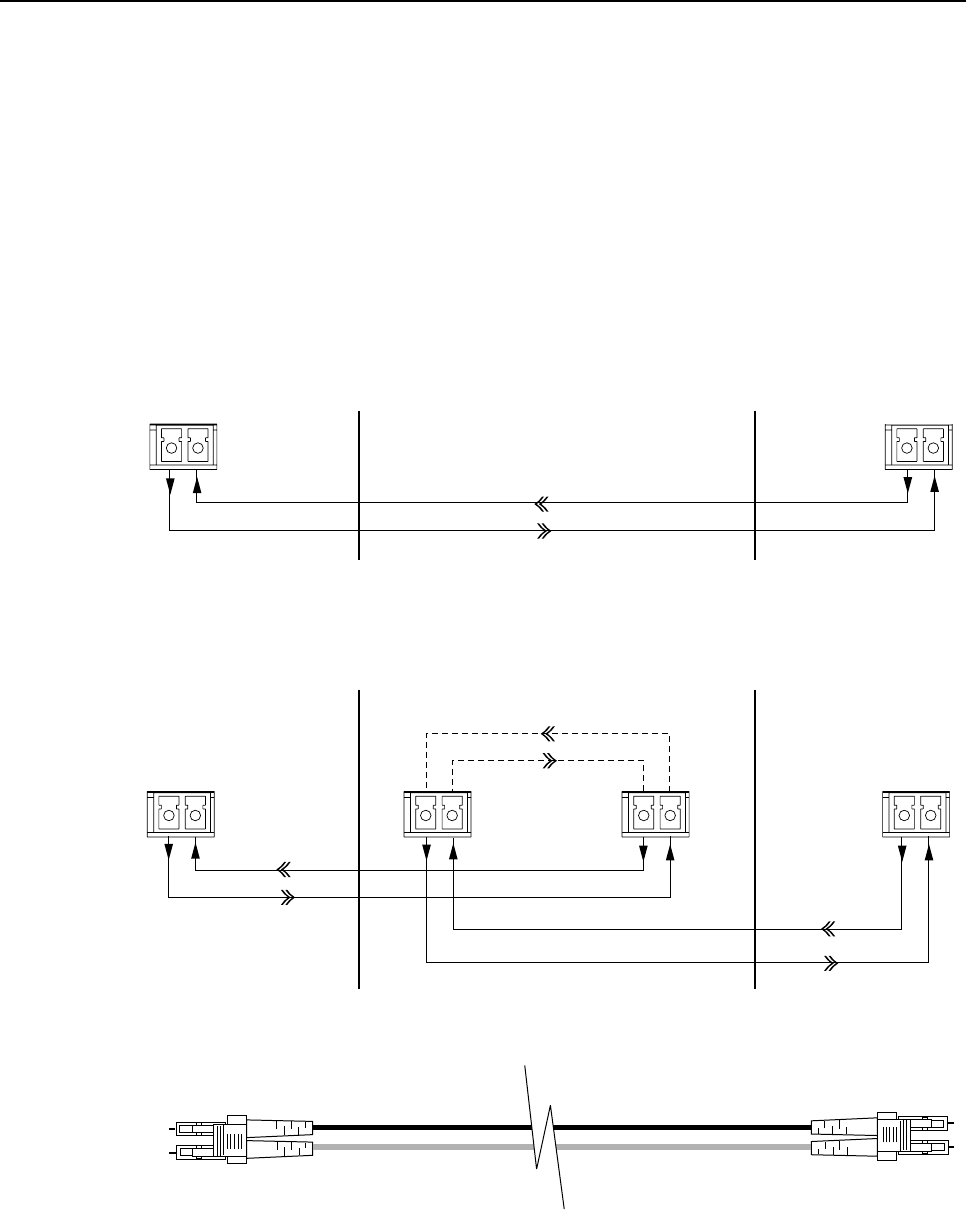
2.4 Optical Options and Requirements
Each DHU and its associated DEUs and DRUs are connected over a pair of fiber optic links.
One link transports the forward path optical signal and the other link transports the reverse
path optical signal. Either 50 or 62.5 micron core multi-mode fiber optic cable may be used
for the optical link. If 50 micron cable is used, the optical link may be up to 750 meters (2461
ft) in length. If 62.5 micron cable is used, the optical link may be up to 500 meters (1,641 ft)
in length. Adiagram of the optical connections is shown in Figure 11.
TX RX
TX RX
TX RX TX RX TX RX TX RX
PORTS 1-6
PORTS
1-6
PORTS 1-6
FIBER PORT
FIBER PORT
HOST
PORT
FORWARD PATH
REVERSE PATH
FORWARD PATH
REVERSE PATH
FORWARD PATH
REVERSE PATH
DIGITAL
REMOTE
UNIT
DIGITAL
REMOTE
UNIT
DIGITAL
HOST
UNIT
DIGITAL
HOST
UNIT
DIGITAL EXPANSION UNIT
BASIC CONFIGURATION WITH DHU AND DRU
BASIC CONFIGURATION WITH DHU, DEU, AND DRU
END-TO-END OPTICAL CONNECTOR/CABLE ASSEMBLY DIAGRAM
Figure 11. Digivance ICS Optical Connections

ADCP-75-110 • Issue 2B • July 2001
Page 21
©2001, ADC Telecommunications, Inc.
Whenever possible, use conduit or aguideway such as the FiberGuide system to route the optical
links between the DHU, the DEUs, and the DRUs. Avoid routing optical fibers through ladder type
cable racks or troughs that do not provide sufficient support to limit bending or prevent accidental
damage. Tie-wrapping is not recommended as ameans of securing fiber optic cables. Provide
sufficient slack at each unit for connecting each fiber to the required port. Fibers may be pre-
terminated or terminated on-site using field-installable LC type connectors.
2.5 Coaxial Cable Requirements
The DHU interfaces either locally (see Figure 8) or remotely (see Figure 9) with the BTS
through coaxial cable connections. In alocal interface with the BTS, coaxial cables are
required to link the DHU with the LIU and the LIU with the BTS. In aremote interface,
coaxial cables are required to link the DHU with the RIU and the RIU with the donor antenna.
The DHU, LIU, and RIU are equipped with N-type female connectors for connecting the
forward and reverse path coaxial cables. Use high performance, flexible, low loss 50-ohm
coaxial communications cable (RG 400 or equivalent) for all coaxial connections.
2.6 System Expansion Planning
The DEU enables 6-way expansion of any optical port. This makes it possible to add more
DRUs without having to install additional DHUs. Each DHU is equipped with six optical
ports. If more than six DRUs are required by the application, aDEU may be connected to one
of the optical ports at the DHU which expands that port to six ports. If still more optical ports
are required, then asecond DEU may be connected to the DHU or a second DEU may be
connected to the first DEU. The ability to cascade DEU’s in parallel or in series provides
unlimited flexibility. It is physically possible to connect an unlimited number DRUs to the
DHU through the installation of DEUs.
The total number of DRU’s that can be served is limited by the cumulative noise effect caused
by antenna combining. This number cannot be determined until the radius distance of
coverage required at the DRU antenna is determined and the path loss attributed to the
structure are known. The system design requires that the carrier to noise differential be greater
than the customer’s desired signal to noise ratio.
If it is likely that the system will be expanded in the future, locate the DHU in such away that it can
either be used as ahub for an expanded system or replaced with aDEU which is then connected to a
relocated DHU. It should also be noted that aDEU can be used as an optical regenerator. ADRU
may sometimes need to be located at apoint that is beyond the 500 or 750 meter limit (depending
on fiber type) imposed by the optical link. The solution is to install aDEU at the maximum optical
link limit (500 or 750 meters) from the DHU. This provides an additional 500 or 750 meters of
optical link beyond the DEU for connecting the DRU.
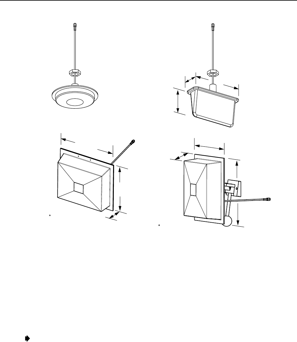
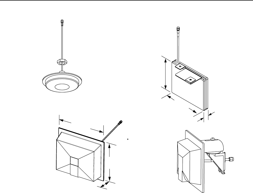
2.7 DRU Antenna Options
Various antennas, shown in Figures 12 and 13, are available from ADC for use with the DRU.
All antennas include a 6 foot (1.8 m) long 50-ohm coaxial cable (equipped with SMA male
connector) for connection to the DRU. The DRU is equipped with an SMA female connector
for connecting the antenna cable.
ADCP-75-110 • Issue 2B • July 2001
Page 22
©2001, ADC Telecommunications, Inc.
DIAMETER - 6.14 INCH (156 MM)
DEPTH - 1.05 INCH (27 MM)
7.26 INCHES
(184 MM)
3.88 INCHES
(99 MM)
2.26 INCHES
(57 MM)
8.65 INCHES
(220 MM)
6.55 INCHES
(166 MM)
2.38 INCHES
(60 MM)
7.90 INCHES
(201 MM)
2.38 INCHES
(60 MM)
8.65 INCHES (220 MM)
4 dBi GAIN
CEILING-MOUNT
HALLWAY
2.5 dBi GAIN CEILING-MOUNT
OMNIDIRECTIONAL
8 dBi GAIN
70 DIRECTIONAL PANEL
(WALL-MOUNT) 7.5 dBi GAIN
90 DIRECTIONAL PANEL
(CORNER MOUNT)
MOUNTING BASE
LENGTH - 3.85 INCHES
(98 MM)
ALL ANTENNAS ARE EQUIPPED WITH
A 72-INCH RG58/U CABLE TERMINATED
WITH A MALE SMA CONNECTOR
MOUNTING STUD
LENGTH - 1.5 INCHES (38 mm)
DIAMETER - 0.875 INCHES (22 MM)
MOUNTING STUD
LENGTH - 1.5 INCHES (38 mm)
DIAMETER - 0.875 INCHES (22 MM)
16237-C
Figure 12. 800 MHz DRU Antenna Options
The DRU antennas are designed for unobtrusive mounting within an office environment. Each
type of antenna provides aspecific coverage pattern in order to accommodate the shape of the
area where coverage is required. The ceiling-mount omni directional antenna is designed to
mount in the center of the coverage area. The directional panel antenna is designed to mount
vertically on one side of the coverage area. The panel antenna (800 MHz only) provides is
designed to mount vertically in the corner of the coverage area. The ceiling mount hallway
antenna is designed to mount in the center of long corridors. Antennas other than those offered
by ADC may also be used if required.
Note:To comply with Maximum Permissible Exposure (MPE) requirements, antennas must
be installed to provide at least 20 centimeters (8 inches) of separation from all persons per
FCC 47 CFR part 2.1091.
ADCP-75-110 • Issue 2B • July 2001
Page 23
©2001, ADC Telecommunications, Inc.
DIAMETER - 4.25 INCH (105 MM)
DEPTH - 0.57 INCH (14 MM) 2.5 INCHES
(64 MM)
0.5 INCHES
(13 MM)
3 INCHES
(76 MM)
5 INCHES
(127 MM)
4.6 INCHES
(118 MM)
1.4 INCHES
36 MM)
4 dBi GAIN
CEILING-MOUNT
HALLWAY
2.5 dBi GAIN CEILING-MOUNT
OMNIDIRECTIONAL
ALL ANTENNAS ARE EQUIPPED WITH
A 72-INCH RG58/U CABLE TERMINATED
WITH A MALE SMA CONNECTOR
MOUNTING STUD
LENGTH - 1.5 INCHES (38 mm)
DIAMETER - 0.875 INCHES (22 MM)
Fig 13-A
MOUNTING BASE
LENGTH - 2.5 INCHES
(64 MM)
7.5 dBi GAIN
90 DIRECTIONAL PANEL
(COMBINATION WALL
AND CORNER MOUNT)
Figure 13. 1900 MHz DRU Antenna Options
2.8 External Alarm System Reporting Requirements
The DHU provides normally open (NO) and normally closed (NC) dry alarm contacts for
reporting minor and major alarms to an external alarm system. Aminor alarm is defined as a
high temperature condition. Amajor alarm is defined as any fault condition except high
temperature. Connections to the alarm contacts are provided through a screw-type terminal
strip. Use category 3 or 5 cable for the alarm wires. If an external alarm system is not in use,
no alarm connections are required.
2.9 Frequency Band Selection Requirements (1900 MHz)
The 1900 MHz version of the DHU and DRU must be configured by the installer to operate in
the appropriate forward and reverse path frequency band. Four band selections (AD, DBE,
BEF, and EFC) are possible. ADIP switch on the underside of each unit is provided for
selecting the required frequency band. The band selection must be done prior to installation
since the DIP switch is usually not accessible after the unit is mounted. Once the required
selection has been made, no further band adjustments are required.

ADCP-75-110 • Issue 2B • July 2001
Page 24
©2001, ADC Telecommunications, Inc.
2.10 Maintenance Requirements
The Digivance ICS requires no regular maintenance to insure continuous and satisfactory
operation. Maintenance, as it applies to the Digivance ICS, primarily involves diagnosing and
correcting service problems as they occur. Faults and failures arising from within the
Digivannce ICS will generate an external alarm response which includes lighting an LED
indicator(s) and closing or opening aset of alarm contacts. When an alarm is reported, it will
be necessary to isolate the source of the problem by observing the LED indicators on each unit
and then performing specified tests to isolate the problem. Once the source of the fault is
isolated, the appropriate action can be taken to correct the problem. The only unit components
that can be replaced are the cooling fans which mount in the DHU and the DEU. The failure of
any other component within aunit will require replacement of the unit. Basic trouble-shooting
procedures are provided in Section 5 of this manual.
2.11 System Design Recommendations
Follow asystematic process when designing an in-building coverage solution. The following
sub sections outline the four phases of the in-building coverage solution design process.
System design and planning services are available from ADC if required. Refer to Section 6of this
manual for additional information.
2.11.1 Phase One – Initial Evaluation
Qualify the Installation: Confirm that there are no extenuating circumstances that would
prevent asuccessful installation such as: extreme cellular system issues (blocking, severe
interference, site problems, etc.), building issues, power issues, or safety issues (site should
not present any hazards or conditions that would make operation of the equipment unsafe).
Analyze the RF Situation: Determine how the system RF link to the outside world will be
provided. Will it beadirect feed from aBTS (microcell) or an over-the-air connection via a
donor antenna? If it is a donor antenna, is the customer within the coverage footprint of a
serving cell or better? The coverage can be determined during the preliminary walkthrough by
checking the downlink Received Signal Strength Indication (RSSI) outside the building with a
unity gain sampling antenna. Sometimes arooftop reading is needed to obtain asufficient
signal level. Note that it is an FCC violation to expand the normal coverage footprint of a
cellular site with an in-building product. In addition, consider the impact the system will have
on traffic, especially the busy hour. Confirm with the service provider that the expected
increase in the volume of calls will be addressed (if needed), possibly with additional
equipment such as additional channels or a microcell.
Determine the Amount of Building Attenuation: If a donor antenna will provide the RF link
to the BTS, determine if there is enough signal isolation between the donor antenna and the in-
building system to avoid afeedback loop and signal degradation. This step can often be
accomplished during the preliminary walkthrough.
Discuss Installation with Building Management and Engineering: Discuss all initially
anticipated Digivance ICS coverage areas (including any obviously desirable cable routings,
equipment installations, power and mechanical requirements) with the authorized client and

ADCP-75-110 • Issue 2B • July 2001
Page 25
©2001, ADC Telecommunications, Inc.
building personnel for an initial approval/confirmation. This gives a good estimate of the
extent of the system work needed. Occasionally, some of the system design work can be
accomplished at this point.
2.11.2 Phase Two – System Design
Determine forward and reverse path loss and then design for unity gain on the uplink
and maximum power out of the DRU on the downlink:The overall purpose of the
Digivance ICS is to transparently overcome attenuation losses, not to provide additional gain
beyond what is required to bring the signal to unity gain. Complete the following steps to
make this determination:
1. Determine the in-building reverse path (uplink) losses at typical operating frequencies
and distances from the subscriber handset (terminal) to the DRU. This information will
be used to determine the optimal uplink signal level to the outside world.
2. Determine the typical composite cell site Effective Radiated Power (ERP) into the
system. Calculate the interface adjustment required to feed the required downlink signal
level to the DHU in order to drive the DRU output signal at the desired level.
Determine the location of the DHU and its RF and AC power sources: Complete the
following steps to make this determination:
1. Determine where and how the DHU will be mounted.
2. Determine the location of the DHU AC power source.
3. Determine the RF source (LIU with BTS or RIU with BTS through donor antenna) for
the DHU.
4. If an LIU connection with the BTS is required, determine the distance to the DHU.
5. If aRIU connection with the BTS is required, determine what type of antenna is needed
and where it can be mounted.
6. Determine the attenuation or amplification requirements for the DHU to BTS interface.
Discuss the design of the Digivance ICS installation with building management and
engineering: Explain the proposed system design with building management and engineering
personnel and obtain final design approval prior to installation.
2.11.3 Phase Three – Installation
Use industry standard practices for cabling, installation, and powering to complete the
following:
1. Install the DHU as described in Section 3 of this manual and adjust the RF interface
levels based on the system design specifications. Additional information concerning the
DHU to BTS interface is provided in the Digivance ICS Remote Interface Unit User Manual
(ADCP-75-113) and in the Digivance ICS Local Interface Unit User Manual (ADCP-75-114).

ADCP-75-110 • Issue 2B • July 2001
Page 26
©2001, ADC Telecommunications, Inc.
2. Install aDRU as described in the Digital Remote Unit Installation Instructions (ADCP -
75-112). If a donor antenna is used, install the DHU and RIU close to the donor antenna.
3. Conduct an initial performance evaluation and complete the following:
a) Confirm proper isolation, signal quality, and power levels.
b) Make test calls from DRU service area and evaluate call quality (confirm with
service provider if desired).
c) Address performance issues as needed.
4. Install the remaining DRUs and also any DEUs as described in the Digital Expansion
Unit Installation Instructions (ADCP-75-111). Test call quality and range of each DRU
as needed.
5. Check powering and alarm functions of entire system per Digivance ICS specifications.
2.11.4 Phase Four - Performance Evaluation
Complete the following to evaluate the performance of the Digivance ICS:
1. Evaluate the forward path (downlink) and reverse path (uplink) RF signal levels and
quality.
2. Make continuous calls from DRU to DRU, checking all service areas, seams, and
coverage boundaries for call quality (both DL and UL). Address all quality issues as
needed.
3. Place calls both leaving and entering the building(s), in parking lots, etc. Address all
quality issues as needed.
4. Contact client/service provider to inform them when the Digivance ICS is operational.
usermanual

ADCP-75-110 • Issue 2B • July 2001
Page 27
©2001, ADC Telecommunications, Inc.
3 DIGITAL HOST UNIT INSTALLATION PROCEDURE
This section provides the installation procedures for the DHU. Installation of the DEU(s) and
DRU(s) may proceed separately from the installation of the DHU. The installation procedures
for the DEU are provided in the Digital Expansion Unit Installation Instructions (ADCP -75-
111) which are shipped with the DEU. The installation procedures for the DRU, the DRU
antennas, and the ac/dc converter (optional DRU accessory) are provided in the Digital
Remote Unit Installation Instructions (ADCP-75-112) which are shipped with the DRU. When
all units of the Digivance ICS have been installed, refer to Section 4 of this manual for the
system power up and test procedures.
3.1 System Plan Review and Pre-Installation Cable Routing
Before beginning the installation, review the system plan with the system engineer. Make sure
each equipment installation site is identified and located and all cable runs are mapped out.
The coaxial, DC power, and fiber optic cables may be routed between the various equipment
locations before the equipment is installed. Whenever possible, route fiber optic cables
through conduit or a guideway such as the FiberGuide system. Avoid routing fibers through
ladder type cable racks or troughs that do not provide sufficient support to limit bending or
prevent accidental damage. Tie-wrapping is not recommended as ameans of securing fiber
optic cables. Make sure to leave sufficient slack at each equipment location for connectorizing
and cable management. The procedures for terminating the cables and for connecting the
cables to the DHU are provided in the sections that follow.
3.2 Tools and Materials
The following tools are required in order to complete the procedures in this section:
• Box cutter
• Pencil or scribe
• Medium and small size flat-bladed screwdrivers
• TORX screwdriver (T20 bit)
• Pliers
• Wire cutters
• Wire stripper
• Non-conductive probe (1900 MHz units only)
• Tool kit for attaching RJ-45 male connectors to category 3 or 5 cable
• Tool kit for attaching N-type male connectors to coaxial cable
• Tool kit for attaching LC connectors to multimode fiber optic cable
• Drill and assorted drill bits (wall-mount installations only)
• Multimeter
• Optical power meter
• Laser light source
FCC ID: F8I-DVICS1900-1

ADCP-75-110 • Issue 2B • July 2001
Page 28
©2001, ADC Telecommunications, Inc.
The following materials are required in order to complete the procedures in this section:
• Wall-mount fasteners (wall-mount applications only)
• #22 AWG (0.40 mm) category 3or 5cable (for power cable and external alarm connections)
• RJ-45 male connectors (for power cable)
• #18 AWG (1.00 mm) insulated stranded copper wire (for chassis grounding wire)
• Ring terminal for #18 wire (for chassis ground wire connection)
• 50 or 62.5 micron core multi-mode fiber optic cable
• LC-type field installable connectors
• High performance, flexible, low loss 50-ohm coaxial cable
• N-type male connectors
• Wire ties
3.3 Unpacking and Inspection
This subsection provides instructions for opening the shipping boxes, verifying that all parts
have been received, and verifying that no shipping damage has occurred. Use the following
procedure to unpack and inspect the DHU:
1. Open the shipping carton and carefully unpack the DHU from the protective packing
material.
2. Check the DHU for broken or missing parts. If there are any damages, contact ADC (see
Section 6at the end of this manual) for an RMA (Return Material Authorization) and to
reorder if replacement is required.
3.4 Frequency Band Selection Procedure (1900 MHz DHU only)
The 1900 MHz version of the DHU may be configured to operate at any one of four frequency
bands. ADIP switch is provided on the underside of the DHU for selecting the required
frequency band. Use the following procedure to set the DIP switch to provide the required
1900 MHz frequency band:
1. Determine the required frequency band for the DHU (AD, DBE, BEF, or EFC) as
specified in the system design plan.
2. Orient the DHU as shown in Figure 14 and then locate the small hole in the bottom of
the DHU that provides access to the band select DIP switch.
3. Use anon-conductive probe to align the DIP switch sliding handles to provide the
required frequency band (see Figure 14).
4. Place the copper sticker provided with the DHU over the small opening that provides
access to the DIP switch.
Note: The copper sticker provides EMI/RFI shielding. Do not use some other type of material
to cover the DIP switch access hole.
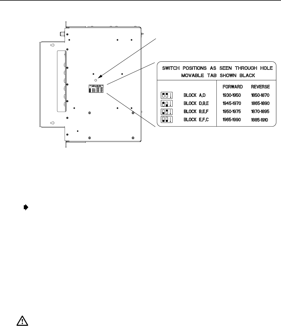
ADCP-75-110 • Issue 2B • July 2001
Page 29
©2001, ADC Telecommunications, Inc.
ALIGN DIP SWITCH HANDLES AS
SHOWN ON THE LABEL TO PROVIDE
SPECIFIED FREQUENCY BAND
Fig 13-A
Figure 14. 1900 MHz DHU Frequency Band Selection
3.5 Mounting Procedure
The DHU may be either rack-mounted or wall-mounted. Of the procedures that follow, use
which ever procedure is appropriate for the installation:
Note: To insure that all optical connectors and transceivers remain dust-free during
installation, leave all dust caps and dust protectors in place until directed to remove
them for connection.
3.5.1 Rack Mount Installation
The DHU may be mounted in either a19-inch or 23-inch EIA or WECO equipment rack. Both
US standard and metric machine screws are included for rack mounting the DHU. When
loading the DHU in arack, make sure the mechanical loading of the rack is even to avoid a
hazardous condition such as aseverely unbalanced rack. The rack should safely support the
combined weight of all the equipment it holds. In addition, the maximum recommended
ambient temperature for the DHU is 50º C (122º F). Allow sufficient air circulation or space
between units when the DHU is installed in amulti-unit rack assembly because the operating
ambient temperature of the rack environment might be greater than room ambient.
Warning:Wet conditions increase the potential for receiving an electrical shock when
installing or using electrically-powered equipment. To prevent electrical shock, never install
or use electrical equipment in awet location or during alightning storm.
Use the following procedure to install the DHU in the equipment rack:
1. The DHU is shipped with the mounting brackets installed for 19-inch rack installations.
If mounting the DHU in a19-inch rack, proceed to step 4. If mounting the DHU in a 23-
inch rack, proceed to step 2.
2. Remove both mounting brackets from the DHU (requires TORX screwdriver with T20 bit)
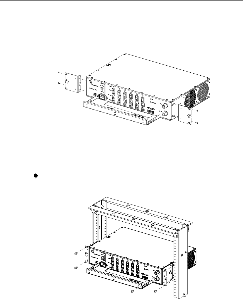
ADCP-75-110 • Issue 2B • July 2001
Page 30
©2001, ADC Telecommunications, Inc.
3. Reinstall both mounting brackets so the long side of the bracket is flush with the DHU
front panel as shown in Figure 15. Use the screws removed in step 2to re-attach the
brackets to the DHU enclosure.
16426-A
REMOVE AND REINSTALL MOUNTING
BRACKETS AS SHOWN FOR
INSTALLATION IN 23-INCH RACKS
Figure 15. Installing the Mounting Brackets for 23-Inch Rack Installations
4. Position the DHU in the designated mounting space in the rack (per system design) and
then secure the mounting brackets to the rack using the four machine screws provided
(use #12-24 screws or M6 x10screws, whichever is appropriate) as shown in Figure 16.
Note:Provide aminimum of 3 inches (76 mm) of clearance space on both the left and
right sides of the DHU for air intake and exhaust.
16165-A
Figure 16. DHU Rack Mount Installation
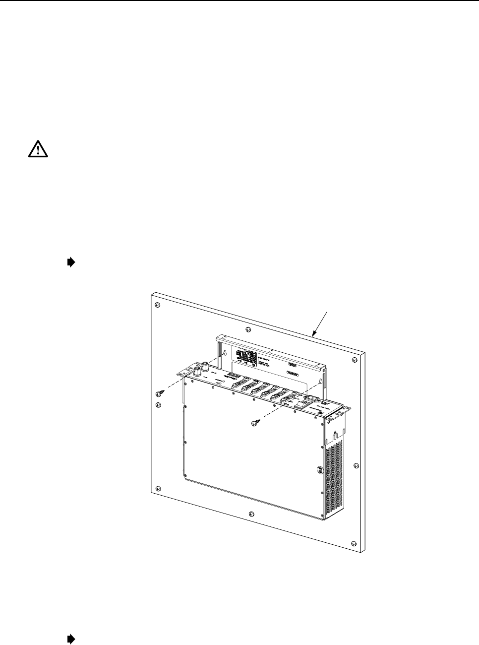
ADCP-75-110 • Issue 2B • July 2001
Page 31
©2001, ADC Telecommunications, Inc.
3.5.2 Wall-Mount Installation
The DHU may be mounted from any flat vertical surface. It is recommended that abacker
board such as 3/4-inch plywood be applied over the mounting surface to provide asecure base
for attaching the DHU. Two mounting holes are provided in the cable management tray for
securing the DHU to the mounting surface. The fasteners must be provided by the installer.
Use the following procedure to wall-mount the DHU:
Warning:Wet conditions increase the potential for receiving an electrical shock when
installing or using electrically-powered equipment. To prevent electrical shock, never install
or use electrical equipment in awet location or during alightning storm.
1. Obtain the appropriate fasteners (lag bolts, screw anchors, etc.) for securing the DHU to
the mounting surface.
2. Position the DHU on the mounting surface in the specified location (per the system
design) with the front panel facing up as shown in Figure 17.
Note:Provide aminimum of 3 inches (76 mm) of clearance space on both the left and
right sides of the DHU for air intake and exhaust.
16427-A
BACKER BOARD SUCH
AS 3/4-INCH PLYWOOD
Figure 17. DHU Wall-Mount Installation
3. Using the DHU as atemplate, mark the location of the mounting holes on the mounting
surface.
Note:The mounting holes in the DHU cable management tray are spaced 11-21/32
inches (296 mm) center to center.
ADCP-75-110 • Issue 2B • July 2001
Page 32
©2001, ADC Telecommunications, Inc.
4. Set the DHU aside and then drill appropriately sized holes in the mounting surface for
the fasteners.
5. Partially install the fasteners in the drilled holes. Leave the head of each fastener
protruding about 1/4 inch (6 mm) from the mounting surface.
6. Hang the DHU from the fasteners and then securely tighten each fastener.
3.6 Chassis Ground Connection
Astud is provided on the rear side of the chassis for connecting agrounding wire to the
chassis. Use the following procedure to connect the grounding wire to the chassis and to route
the grounding wire to an approved earth ground source:
1. Obtain alength of #18 AWG (1.00 mm) insulated stranded copper wire for use as a
chassis grounding wire.
2. Terminate one end of the wire with aring terminal.
3. Locate the chassis ground stud at the rear of the DHU as shown in Figure 18.
16169-A
Figure 18. Chassis Ground Stud
4. Attach the ring end of the wire to the chassis ground stud (see Figure 18).
5. Route the free end of the chassis grounding wire to an approved (per local code or
practice) earth ground source.
6. Cut the chassis grounding wire to length and connect it to the approved ground source as
required by local code or practice.
Note:Be sure to maintain reliable grounding for rack and wall mounted equipment. Pay
particular attention to ground source connections.
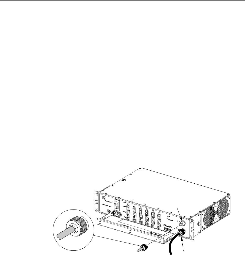
ADCP-75-110 • Issue 2B • July 2001
Page 33
©2001, ADC Telecommunications, Inc.
3.7 Coaxial Cable Connections
The RF interface between DHU and the BTS is supported through apair of type Nfemale
connectors mounted on the DHU front panel. One connector provides the coaxial cable
connection for the forward path (downlink) signal. The other connector provides the coaxial
cable connection for the reverse path (uplink) signal. Coaxial cables link the DHU to the BTS
through an interface device such as the LIU or the RIU. Use the following procedure to install
the forward and reverse path coaxial cables and connect them to the DHU:
1. Obtain the required lengths of high performance, flexible, low loss 50-ohm coaxial
communications cable (RG 400 or equivalent) for all coaxial connections.
2. Route the forward path and reverse path coaxial cables (if not already routed) between
the DHU and the specified BTS interface device (per system design) and cut to the
required length. Allow sufficient slack for dressing and organizing cables at the DHU.
3. Terminate each cable with atype Nmale connector following the connector supplier’s
recommendations.
4. Connect the forward path cable to the RF IN connector on the DHU front panel as
shown in Figure 19.
5. Connect the reverse path cable to the RF OUT connector on the DHU front panel as
shown in Figure 19.
16428-A
TYPE-N MALE CONNECTOR RF IN CONNECTOR
(FORWARD PATH)
RF OUT CONNECTOR
(REVERSE PATH)
Figure 19. Forward and Reverse Path Coaxial Cable Connections
6. Dress and secure cables at the DHU per standard industry practice.
7. Connect the forward and reverse path cables to the LIU (microcell) or the RIU (donor
antenna) as specified in the instructions provided with that unit.
8. Complete all remaining coaxial cable connections between the LIU and the BTS or
between the RIU and the donor antenna as specified in the instructions provided with the
interface unit.

ADCP-75-110 • Issue 2B • July 2001
Page 34
©2001, ADC Telecommunications, Inc.
3.8 Ports 1–6 Optical Connections
The optical interface between the DHU and each DEU or DRU is supported by six optical
ports. Each of the six optical ports provides aduplex LC type optical transceiver which is
mounted on the DHU front panel. One side of the transceiver provides the optical fiber
connection for the forward path (downlink) signal. The other side of the transceiver provides
the optical fiber connection for the reverse path (uplink) signal. Use the following procedure to
install the forward and reverse path optical fibers and to connect them to the DHU:
Danger:This equipment uses aClass 1Laser according to FDA/CDRH rules. Laser radiation
can seriously damage the retina of the eye. Do not look into the ends of any optical fiber. Do
not look directly into the optical transceiver of any digital unit or exposure to laser radiation
may result. An optical power meter should be used to verify active fibers. Aprotective cap or
hood MUST be immediately placed over any radiating transceiver or optical fiber connector
to avoid the potential of dangerous amounts of radiation exposure. This practice also prevents
dirt particles from entering the transceiver or connector.
1. Obtain the required lengths of 50 or 62.5 micron core multi-mode fiber optic cable.
2. Route the fiber optic cable between the DHU and the DEU or DRU (if not already
routed) and cut to required length. Allow sufficient slack for dressing and organizing the
cables at each unit. Maintain aminimum bend radius of 2 inches (50 mm).
Note:The maximum distance for routing 50 micron core fiber optic cable is 750 meters
(2,461 feet). The maximum distance for routing 62.5 micron core fiber optic cable is 500
meters (1,641 feet).
3. Terminate each optical fiber with afield-installable LC type fiber optic connector as
shown in Figure 20. Follow the instructions provided by the connector manufacturer for
installing the connector.
4. Test each fiber for optical loss as described in Subsection 5.4.2 of this manual.
5. Designate one of the fibers as the forward path link and the other as the reverse path link
and attach an identification tag to each fiber end next to the connector.
6. Use the plastic joiner provided with the LC connectors to join the DHU Port 1forward
and reverse path connectors together (see Figure 20). Make sure the forward path and
reverse path connectors are oriented as shown.
Note:When viewing any Port 1-6 optical transceiver from the front, the forward path port is
on the left and the reverse path port is on the right.
7. Remove the dust caps from the optical fiber connectors and the port 1optical transceiver.
Note:Leave the dust cap in place on any unused optical port.
8. Clean each connector (follow connector supplier’s recommendations) and then insert the
optical link connector pair into DHU optical port 1 (see Figure 20).
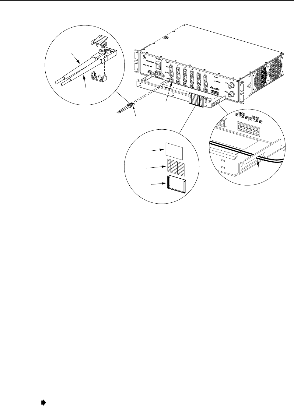
ADCP-75-110 • Issue 2B • July 2001
Page 35
©2001, ADC Telecommunications, Inc.
16429-B
REVERSE PATH (RX)
CONNECTOR
FORWARD PATH (TX)
CONNECTOR
OPTICAL CONNECTOR
ASSEMBLY DETAIL
PORT 1
OPTICAL
TRANSCEIVER
OPTICAL
CONNECTOR
CABLE
GUIDES
CABLE GUIDE
DETAIL
DESIGNATION CARD AND
HOLDER DETAIL
HOLDER
CARD
CLEAR
PLASTIC
COVER
Figure 20. Ports 1–6 Fiber Optic Cable Connections
9. Place the optical fibers within the cable guides provided on the cable management tray (see
Figure 20) and then dress and secure the fibers at the DHU per standard industry practice.
10. Connect the forward and reverse path optical fibers to the DEU or the DRU as specified
in the instructions provided with that unit.
11. Use the designation card provided (see Figure 20) to indicate the location and name of
the DRU or DEU that is connected to the optical fibers. The designation card holder may
be attached to any convenient flat surface such as the DHU cable management tray
12. Repeat steps 1–11 for each remaining optical port.
3.9 DC Power Connections
The DC power interface between the DHU and each DRU is supported by six RJ-45 female
connectors. Each DHU RJ-45 connector provides nominal 48 Vdc power for the associated
DRU except when the DRU is powered with an ac/dc converter. A category 3 or 5 twisted pair
cable is used to feed the power from the DHU to the DRU. Use the following procedure to
install the DC power cable and to connect it to the DHU.
1. Obtain the required length of category 3 or 5 twisted pair cable.
2. Route the cable between the DHU and the DRU (unless already routed) and then cut to
required length. Allow sufficient slack for dressing and organizing the cable at the DHU.
Note:The maximum distance for routing power cable is 500 meters (1,641 feet).
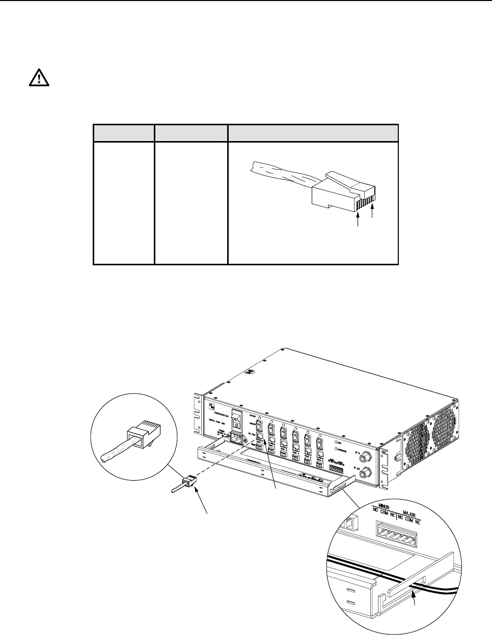
ADCP-75-110 • Issue 2B • July 2001
Page 36
©2001, ADC Telecommunications, Inc.
3. Terminate each end of the cable with amale RJ-45 connector. Match the wire color to
the connector pin as specified in Table 6.
Caution:The DRU will be damaged if the RJ-45 connector is wired incorrectly.
Table 6. RJ-45 Connector Pin Designations
PIN NUMBER WIRE COLOR CONNECTOR PINS
1
2
3
4
5
6
7
8
White/Green
Green
White/Orange
Orange
White/Blue
Blue
White/Brown
Brown
PIN
1
PIN
8
+48 VDC ON PINS 1, 3, 5, AND 7
RETURN ON PINS 2, 4, 6, AND 8
16180-A
4. Perform acontinuity test to verify that each wire is properly connected to the terminating
RJ-45 connector and check the connector for correct polarity (see diagram in Table 6).
5. Connect the DC power cable to the DHU port 1 DC PWR jack as shown in Figure 21.
16430-A
RJ-45 CONNECTOR
DETAIL
PORT 1
DC POWER
CONNECTOR
RJ-45
CONNECTOR
CABLE
GUIDES
CABLE GUIDE
DETAIL
1
8
Figure 21. 48 Vdc Power Cable Connection
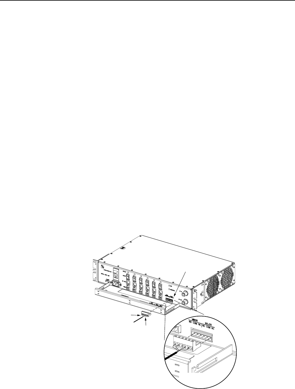
ADCP-75-110 • Issue 2B • July 2001
Page 37
©2001, ADC Telecommunications, Inc.
6. Place the DC power cable within the cable guides provided (see Figure 21) and then
dress and secure the cable at the DHU per standard industry practice.
7. Connect the DC power cable to the DRU as specified in the instructions provided with
that unit.
8. Repeat steps 1–7 for each remaining DRU that will be powered by the DHU.
3.10 Extermal Alarm System Connections
The alarm interface between the DHU and an external alarm system is supported by a six-
terminal plug (with screw-type terminals) that connects to areceptacle mounted on the DHU
front panel. The terminal plug provides connections to normally open (NO) and normally
closed (NC) dry type alarm contacts for both minor and major alarms. Acategory 3 or 5 cable
is typically used to connect the DHU to the external alarm system. Use the following
procedure to install the alarm wiring and connect it to the DHU:
1. Obtain the required length of category 3 or 5 cable.
2. Route the cable between the DHU and the external alarm system (if not already routed)
and then cut to required length. Allow sufficient slack for dressing and organizing the
cable at the DHU.
3. Strip back the outer cable sheath and insulation to expose the wires at both ends of the
cable and strip back 0.2 inches (5 mm) of insulation each wire.
4. Connect the Major alarm wire pair to the MAJOR COM/NC or MAJOR COM/NO
terminals (whichever is required by the external alarm system) on the DHU alarm
terminal connector (supplied with DHU) as shown in Figure 22.
16370-A
ALARM
CONNECTOR
MAJOR
ALARM
WIRES
MINOR
ALARM
WIRES
ALARM CONNECTOR
DETAIL
Figure 22. External Alarm System Connections
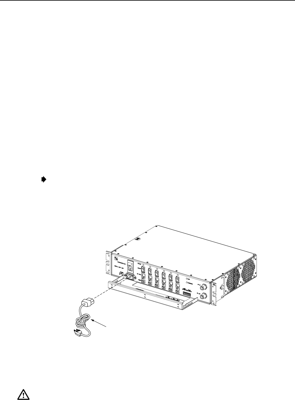
ADCP-75-110 • Issue 2B • July 2001
Page 38
©2001, ADC Telecommunications, Inc.
5. Connect the Minor alarm wire pair to the MINOR COM/NC or MINOR COM/NO
terminals (whichever is required by the external alarm system) on the DHU alarm
terminal connector as shown in Figure 22.
6. Connect the Major and Minor alarm wire pairs to the appropriate terminals on the
external alarm system.
7. Dress and secure cable per standard industry practice.
3.11 AC Power Connections
The AC power interface between the DHU and the AC power source is supported by a 3-wire
AC power cord connector located on the DHU front panel. The AC connector provides a
connection point for the power cord which is provided separately with the DHU. Use the
following procedure to install the AC power cord:
1. Locate the AC power cord which is provided separately with the DHU. Use only the AC
power cord provided with the DHU or an equivalent UL/CUL listed 3-conductor, 18
AWG cord terminated in amolded-on plug cap rated 125 V, 15 A with amaximum
length of 6 feet (1.8 m).
Note:The DHU is intended to be used with a 3-wire grounding type plug which has a
grounding pin. Equipment grounding is required to ensure safe operation. Do not defeat
the grounding means. Verify DHU is reliably grounded when installed.
2. Place the DHU AC power ON/OFF switch, shown in Figure 23, in the OFF position
(press O).
16431-A
AC POWER CORD
Figure 23. AC Power Connection
3. Connect the receptacle end of the power cord to the AC connector on the DHU.
4. Route the plug end of the power cord to the specified AC outlet (per the system design)
and connect plug to outlet.
Warning:The current rating of the DHU is 2.0 Amps at 120 Vac.Avoid overloading circuits
which may cause damage to over-current protection devices and supply wiring.

ADCP-75-110 • Issue 2B • July 2001
Page 39
©2001, ADC Telecommunications, Inc.
5. Dress and secure cable per standard industry practice.
6. When all units of the Digivance ICS have been installed, refer to Section 4 of this
manual for the system power up and test procedures.
3.12 Create As-Built Drawing
Following installation, create an “as-built” drawing of the complete Digivance ICS system.
Using adrawing of the building floor plan, show the installed location of each piece of
equipment including the various Digivance electronic units, the antennas, the interface units,
and the microcell (if used). In addition, show the location and routing of all copper, coaxial,
and fiber optic cable runs used with the system. Retain the as-built drawing for reference when
troubleshooting or when planning for system expansion.

ADCP-75-110 • Issue 2B • July 2001
Page 40
©2001, ADC Telecommunications, Inc.
4 SYSTEM OPERATION
This section provides guidelines for turning-up the Digivance ICS, verifying that all units are
operating properly, testing to ensure that all performance requirements are satisfied, and
correcting any installation problems. This process assumes that the various units that comprise
the Digivance ICS have been installed in accordance with the system design plan and the BTS
interface unit (LIU or RIU) has been installed and tested. The procedures for installing and
testing the LIU or RIU are provided in the user manual that is shipped with the unit.
4.1 Tools and Materials
The following tools and materials are required in order to complete the procedures in this
section:
• Portable spectrum analyzer
• Portable test transmitter
• Cell phone
• Pencil or pen
• Writing pad
4.2 Turn-Up System and Verify Operation
The process of turning-up the system and verifying operation involves powering up the
various system components and then verifying that the LED indicators show normal operation.
Refer to Tables 7, 8, and 9as needed for acomplete description of the unit LED indicators.
Use the following procedure to power-up the system. If any unit does not respond as
described, refer to Subsection 4.3 for the correction procedures.
1. Temporarily disconnect the alarm system or notify alarm system provider that testing is
in progress.
2. Verify that each AC powered unit is connected to the appropriate outlet.
3. Place the ON/OFF switch on the DHU in the ON position (press I).
4. Verify that the UNIT LED and the OVERDRIVE LED on the DHU turn yellow (for
approximately 6seconds) and then green.
5. Place the PORT 1ON/OFF switch on the DHU in the ON position (press I).
6. If aDEU is connected to port 1, proceed to step 7. If aDRU is connected to port 1, skip
steps 7and 8and proceed to step 9.
7. Place the ON/OFF switch on the DEU in the ON position (press I).
8. Verify that the UNIT LED on the DEU turns yellow (for approximately 6seconds) and
then green.
9. Verify that the PORT 1OK/NOK LED on the DHU turns yellow (for approximately 6
seconds) and then green.

ADCP-75-110 • Issue 2B • July 2001
Page 41
©2001, ADC Telecommunications, Inc.
10. If aDEU is connected to PORT 1, proceed to step 11. If aDRU is connected to PORT 1,
skip steps 11 through 13 and proceed to step 14.
11. Verify that the HOST PORT LED on the DEU turns green.
12. Place the PORT 1ON/OFF switch on the DEU in the ON position (press I).
13. Verify that the PORT 1OK/NOK LED on the DEU turns yellow (for approximately six
seconds) and then green.
14. Verify that the STATUS LED on the DRU connected to PORT 1turns yellow (for
approximately six seconds) and then green.
15. Repeat the procedure covered in steps 5through 14 for each of the remaining DHU
optical ports (ports 2through 6) that is connected to aDEU or a DRU.
16. Reconnect the alarm system and notify alarm system provider that system is operational.
Table 7. Digital Host Unit LED Indicators
INDICATOR COLOR DESCRIPTION
UNIT
LED Green
Yellow
Red
Off
Indicates when the DHU is normal or faulty.
DHU in normal state, no faults detected.
DHU in power-up state or DHU high temperature fault detected. (see Note)
DHU fault detected (see Note).
AC power off to DHU or DHU internal fault.
PORT 1–6
OK/NOK
LEDs Green
Yellow
Red
Red
(blinking)
Off
Indicates if any connected DEU or DRU is normal or faulty or if the
optical inputs from any connected DEU or DRU are normal or lost.
All connected units in normal state, no faults detected.
DHU in power-up state or high temperature fault detected in DEU. (see Note)
Fault detected in any connected DEU or DRU, *no reverse path optical
signal from any connected DEU or DRU detected, or excessive reverse
path errors detected from any connected DEU or DRU. (see Note)
*No reverse path optical signal from any connected DEU or DRU detected,
Port disabled (via front panel switch) or DHU internal fault.
*Early versions of the DHU use a steady red LED to indicate all major
fault conditions. Later versions of the DHU use a blinking red LED to
indicate no optical signal received from the connected DRU or DEU.
OVERDRIVE
LED
Green
Yellow
Red
Indicates when the forward path RF input is below or above the
overdrive threshold.
RF input signal level at DHU below overdrive threshold.
DHU in power-up state.
RF input signal level at DHU above overdrive threshold.
Note:Detection of any fault will generate an alarm. A high temperature fault will generate aminor
alarm (yellow LED). All other types of faults will generate amajor alarm (red LED).
FCC ID: F8I-DVICS1900-1

ADCP-75-110 • Issue 2B • July 2001
Page 42
©2001, ADC Telecommunications, Inc.
Table 8. Digital Expansion Unit LED Indicators
INDICATOR COLOR DESCRIPTION
UNIT
LED Green
Yellow
Red
Off
Indicates when the DEU is normal or faulty.
DEU in normal state, no faults detected.
DEU in power-up state or DEU high temperature fault detected. (see Note)
DEU internal fault detected. (see Note)
AC power off to DEU or DEU internal fault.
HOST PORT
LED
Green
Red
(steady or
blinking)
Off
Indicates when the optical inputs from the DHU or supporting
DEU are normal or lost.
DHU or supporting DEU in normal state, no faults detected.
No forward path optical signal from DHU or supporting DEU detected
or excessive forward path errors detected. (see Note).
DEU internal fault.
PORT 1–6
OK/NOK
LEDs Green
Yellow
Red
Red
(blinking)
Off
Indicates if any connected DEU or DRU is normal or faulty or if the
optical inputs from any connected DEU or DRU are normal or lost.
DRU or remote DEU in normal state, no faults detected.
DEU in power-up state.
Fault detected in any connected DEU or DRU, *no reverse path optical
signal from any connected DEU or DRU detected, or excessive reverse
path errors detected from any connected DEU or DRU. (see Note)
*No reverse path optical signal from any connected DEU or DRU
detected.
Port disabled (via front panel switch) or DEU internal fault.
*Early versions of the DEU use a steady red LED to indicate all major
fault conditions. Later versions of the DEU use a blinking red LED to
indicate no optical signal received from the connected DRU or DEU.
Note:Detection of any fault will generate an alarm. A high temperature fault will generate aminor
alarm (yellow LED). All other types of faults will generate amajor alarm (red LED).
Table 9. Digital Remote Unit LED Indicator
INDICATOR COLOR DESCRIPTION
STATUS
LED
Green
Yellow
Red
Red
(blinking)
Off
Indicates if the DRU is normal or faulty or if the forward path optical
inputs to the DRU are normal or lost.
DRU in normal state, no faults detected.
DRU in power-up state.
DRU internal fault detected, *no forward path optical signal detected, or
excessive forward path errors detected. (See Note)
*No forward path optical signal from the DHU or DEU detected.
DC power off to DRU or DRU internal fault.
*Early versions of the DRU use a steady red LED to indicate all major
fault conditions. Later versions of the DRU use a blinking red LED to
indicate no optical signal received from the DHU or DEU.
Note:Detection of any fault will generate an alarm. A high temperature fault will generate
aminor alarm (yellow LED). All other types of faults will generate amajor alarm (red LED).
ADCP-75-110 • Issue 2B • July 2001
Page 43
©2001, ADC Telecommunications, Inc.
4.3 Correct Installation Problems
Use the procedures outlined in Table 10 to troubleshoot various installation problems.
Table 10. Troubleshooting Installation Problems
PROBLEM 1 All LED indicators on the DHU or DEU stay off when the ON/OFF switch is placed in the ON position.
DHU OR DEU = RED
= OFF
= GREEN
16432-A
POSSIBLE CAUSE CORRECTIVE ACTION/COMMENTS
1. AC power source is turned off.
2. Faulty AC power cord.
3. Faulty DHU or DEU.
1. Verify that the AC circuit breaker is turned on or
that afunctional fuse is installed.
2. Test AC power cord and repair/replace as required.
3. Replace faulty DHU or DEU
PROBLEM 2 The UNIT LED indicator on the DHU or DEU is RED.
DHU OR DEU = RED
= OFF
= GREEN
16433-A
POSSIBLE CAUSE CORRECTIVE ACTION/COMMENTS
1. Faulty DHU or DEU. 1. Replace faulty DHU or DEU
PROBLEM 3 The OVERDRIVE LED indicator on the DHU is RED.
DHU = RED
= GREEN
16434-A
POSSIBLE CAUSE CORRECTIVE ACTION/COMMENTS
1. Forward path RF input level at the DHU is
too high 1. Reduce forward path gain by inserting additional
attenuation in the forward path signal.
PROBLEM 4 The OK/NOK LED indicator on the DHU or DEU is steady RED or blinking RED and the STATUS
indicator on the corresponding DRU is GREEN.
DHU OR DEU
FORWARD PATH LINK
REVERSE PATH LINK
DRU 3 = RED
= GREEN
16435-A
POSSIBLE CAUSE CORRECTIVE ACTION/COMMENTS
1. Faulty reverse path optical link.
2. Faulty optical transmit port at DRU.
3. Faulty optical receive port at DHU or DEU.
1. Test optical link and repair or replace as required.
2. Test DRU with optical loopback. Replace if faulty.
3. Connect optical link to another optical port at
the DHU or DEU. If problem is corrected,
replace the DHU or DEU.
PROBLEM 5 The OK/NOK LED indicator on the DHU or DEU is GREEN and the STATUS indicator on the
corresponding DRU is RED.
DHU OR DEU
FORWARD PATH LINK
REVERSE PATH LINK
DRU 3 = RED
= GREEN
16436-A
POSSIBLE CAUSE CORRECTIVE ACTION/COMMENTS
1. Faulty forward path optical link. (Early
version of DHU only)
2. Faulty optical receive port at DRU.
3. Faulty optical transmit port at DHU or DEU.
1. Test optical link and repair or replace as required.
2. Replace DRU.
3. Connect optical link to another optical port at
the DHU or DEU. If problem is corrected,
replace the DHU or DEU.
(continued)
ADCP-75-110 • Issue 2B • July 2001
Page 44
©2001, ADC Telecommunications, Inc.
Table 10. Troubleshooting Installation Problems, continued
PROBLEM 6 The OK/NOK LED indicator on the DHU or DEU is RED or blinking RED and the STATUS indicator
on the corresponding DRU is RED or blinking RED.
DHU OR DEU
FORWARD PATH LINK
REVERSE PATH LINK
DRU 3 = RED
= GREEN
16437-A
POSSIBLE CAUSE CORRECTIVE ACTION/COMMENTS
1. Forward and reverse path optical links
reversed.
2. Faulty forward and reverse path optical links.
3. Faulty DHU, DEU, or DRU.
1. Verify forward and reverse path optical
connections at the DHU or DEU are correct.
2. Test optical links and repair or replace as required.
3. Replace defective unit.
PROBLEM 7 The OK/NOK LED indicator on the DHU or DEU is RED or blinking RED and the HOST PORT LED
indicator on the corresponding remote DEU is GREEN.
DHU OR DEU
FORWARD PATH LINK
REVERSE PATH LINK REMOTE DEU
(Port 3)
= RED
= OFF
= GREEN
16438-A
POSSIBLE CAUSE CORRECTIVE ACTION/COMMENTS
1. Faulty reverse path optical link.
2. Faulty optical transmit port at remote DEU.
3. Faulty optical receive port at DHU or DEU.
1. Test optical link and repair or replace as required.
2. Replace remote DEU.
3. Replace DHU or DEU.
PROBLEM 8 The OK/NOK LED indicator on the DHU or DEU is GREEN and the HOST PORT LED indicator on
the corresponding remote DEU is RED or blinking RED.
DHU OR DEU
FORWARD PATH LINK
REVERSE PATH LINK REMOTE DEU
(Port 3) = RED
= OFF
= GREEN
16439-A
POSSIBLE CAUSE CORRECTIVE ACTION/COMMENTS
1. Faulty forward path optical link.
2. Faulty optical receive port at remote DEU.
3. Faulty optical transmit port at DHU or DEU.
1. Test optical link and repair or replace as required.
2. Replace remote DEU.
3. Replace DHU or DEU.
PROBLEM 9 The OK/NOK LED indicator on the DHU or DEU is RED or blinking RED and the HOST PORT LED
indicator on the corresponding remote DEU is RED or blinking RED.
DHU OR DEU
FORWARD PATH LINK
REVERSE PATH LINK REMOTE DEU
(Port 3) = RED
= OFF
= GREEN
16440-A
POSSIBLE CAUSE CORRECTIVE ACTION/COMMENTS
1. Forward and reverse path optical links
reversed.
2. Faulty forward and reverse path optical links.
1. Switch forward and reverse path optical
connections at the DHU or DEU.
2. Test optical links and repair or replace as required.
PROBLEM 10 The STATUS LED indicator on the DRU stays OFF when the PORT 1-6 ON/OFF switch at the DHU or
DEU is placed in the ON position or when the ac/dc converter is connected.
DHU OR DEU
FORWARD PATH LINK
REVERSE PATH LINK
DRU 3 = RED
= OFF
= GREEN
16441-A
POSSIBLE CAUSE CORRECTIVE ACTION/COMMENTS
1. Faulty DC power cord or plug not seated.
2. DC power cord too long.
3. Insufficient DC power output from DHU,
DEU, or ac/dc converter.
1. Test DC power cord and plug. Correct as required.
2. Verify power cord does not exceed 500 meters.
3. Verify DC voltage level at DRU is between 34
and 48 Vdc. Replace DHU, DEU, or ac/dc
converter if voltage is outside specified range.

ADCP-75-110 • Issue 2B • July 2001
Page 45
©2001, ADC Telecommunications, Inc.
4.4 Test System Performance
Testing the performance of the system involves completing various RF tests and telephone
service tests that verify if the system is functioning properly. Use the following procedure to
test the system performance:
1. Verify that the forward path (downlink) input signal level at the DHU is optimized. The
peak COMPOSITE forward path input signal level at the DHU should be set at
–20 dBm.
Note:In aCDMA system, the power level is dependent on the traffic. For optimum
operation in aCDMA system, the input signal level should be set below the level of the
pilot signal. Adjust level based upon observation of overload indicator during traffic
peaks (busy hour).
2. Verify that the reverse path (uplink) signal level at the local BTS or donor antenna is
optimized. Note that the reverse path output signal level required is dependent on service
provider signal to noise requirements, ICS system noise floor, the service provider
equipment, and the system configuration.
3. Check and record the Received Signal Strength Indication (RSSI) and any spurious
emission levels at and between all DRU antennas. Analyze all DRUs and the DHU
interface using aspectrum analyzer.
4. Plot the RSSI levels on a floor plan of the building and check against the pre-installation
RSSI levels to determine the overall and average RSSI improvement attributed to the
Digivance ICS. Check the entire Digivance coverage area.
5. Verify call processing and voice quality within the coverage areas. Initiate and receive
multiple long and short duration calls. Document the performance and address any issues
as calls are processed within the entire coverage area. Assuming a properly functioning
server RF link and BTS and a properly designed and optimized ICS system, there should
be no clicks, mutes, clipping, or crackles within the coverage area. In awireless office
application, hand off will not occur.
6. If the DHU interfaces with alocal BTS (microcell), verify the handoff function by
placing acall and confirming handoffs between the Digivance/microcell coverage area
and the outdoor macrocell coverage area (macro system) and vice versa. The handoff
should take place without any noticeable call quality or performance issues.
7. If the DHU interfaces with aremote BTS through a donor antenna, verify call quality by
placing acall and then walking between the Digivance coverage area and an area
receiving good coverage directly from the cell site base station. There should be no
noticeable difference in call quality.
8. Following service provider guidelines, test the 411 and 911 links to verify the routing of
emergency and special services calls on local BTS configurations.
9. Verify that the alarm reporting system functions properly by turning the DHU off. This
should generate amajor alarm and operate aset of alarm contacts. Check for alarm
confirmation from the service provider’s local switch and Network Operations Center
(NOC). Aminor alarm (high temperature fault condition) can be checked by opening or
closing (which ever applies) the minor alarm lead wires at the DHU. Note that this tests
only the external alarm system and does not verify operation of the Digivance alarm
reporting system.

ADCP-75-110 • Issue 2B • July 2001
Page 46
©2001, ADC Telecommunications, Inc.
5 SYSTEM MAINTENANCE PROCEDURES
This section explains the alarm reporting system, provides amethod for isolating and
troubleshooting faults, and provides procedures for replacing the DHU or DEU cooling fans.
The Digivance ICS requires no regular maintenance to insure continuous and satisfactory
operation. Maintenance, as it applies to the Digivance ICS, primarily involves diagnosing and
correcting service problems as they occur. When an alarm is reported, it will be necessary to
follow asystematic troubleshooting procedure to locate the problem. Once the source of the
problem is isolated, the appropriate corrective action can be taken to restore service. The only
unit components that can be replaced are the cooling fans which mount in the DHU and DEU.
The failure of any other component within aunit will required replacement of that unit.
5.1 Tools and Materials
The following tools and materials are required in order to complete the procedures in this
section:
• ESD wrist strap
• IR filtering safety glasses
• Optical loopback device (such as Stratos Lightwave LC5-103-03) and LC duplex adapter
• Optical power meter
• Magnification device for inspecting LC connectors
• Laser light source
• Multimeter
• Cell phone
• RJ-45 circuit access tool (such as the Harris 8-wire Banjo Adapter)
• Medium and small size flat-bladed screwdrivers
• TORX screwdriver (T10)
5.2 Fault Detection and Alarm Reporting
Detection of a fault by the Digivance ICS will generate an external alarm response. LED
indicators are provided on the front panel of the various units to indicate when afault is
detected. In addition to LED indicators, the DHU also provides normally open (NO) and
normally closed (NC) dry alarm contacts for reporting minor and major alarms to an external
alarm system. Aminor alarm is defined as ahigh temperature condition. Amajor alarm is
defined as any fault condition except high temperature.
When the DHU alarm contacts are connected to an external alarm system, detection of a fault
will generate an alarm at the Network Operations Center (NOC). However, various types of
faults may not generate an alarm response. In this case, the first indication of a problem will
probably be from cell phone users reporting aloss of service or poor service. Whenever a
problem is reported, whether by a external alarm system or by a call from auser, refer to
Subsection 5.3 to isolate and correct the fault.

ADCP-75-110 • Issue 2B • July 2001
Page 47
©2001, ADC Telecommunications, Inc.
5.3 Fault Isolation and Troubleshooting
Table 11 provides fault isolation and troubleshooting guidelines. When aproblem is reported,
note the type of alarm generated (minor, major, or none) and any problems that may be
observed. Then check the LED indicators on the DHU and note any that are red, yellow, or
off.If aPort 1–6 OK/NOK LED indicator is any color but green, check the LED indicators on
the connected DEUs and/or DRUs. When the required information has been obtained, locate
the problem in Table 11, check out the suggested possible causes, and take corrective action as
required.
Table 11. Fault Isolation and Troubleshooting
Alarm Type Minor
LED Indicators DHU or DEU: UNIT - Yellow - All other LEDs are green
Problem The DHU or DEU is overheating.
POSSIBLE CAUSE CORRECTIVE ACTION/COMMENTS
1. Air intake or exhaust openings to DHU or
DEU chassis blocked.
2. Ambient temperature > 50º C/122º F.
3. Faulty fan.
1. Remove cause of air-flow blockage.
2. Reduce ambient temperature.
3. Replace fan (see Subsection 5.5).
Alarm Type Major
LED Indicators DHU or DEU: UNIT - Red
Problem The DHU or DEU detects an internal circuitry fault.
POSSIBLE CAUSE CORRECTIVE ACTION/COMMENTS
1. Faulty DHU or DEU. 1. Replace DHU or DEU.
Alarm Type Major
LED Indicators DHU or DEU:
DRU: OK/NOK - Red or blinking Red - All other LEDs are green
STATUS - Off
Problem The DRU is not powered.
POSSIBLE CAUSE CORRECTIVE ACTION/COMMENTS
1. DC power cable open.
2. No power or insufficient power output from
ac/dc power converter, DHU, or DEU.
3. Faulty DRU.
1. Test cable for continuity and repair or replace if
faulty.
2. Check DC voltage level at the DRU (see Subsection
5.4.3). Replace converter, DHU, or DEU (whichever
applies) if voltage is not within 34 to 48 Vdc.
3. Replace DRU.
Alarm Type Major
LED Indicators DHU or DEU:
DRU: All LEDs are green
STATUS - Red or blinking Red
Problem The DRU is not receiving an optical signal from the DHU or DEU.
POSSIBLE CAUSE CORRECTIVE ACTION/COMMENTS
1. Faulty forward path optical link between
DHU or DEU and DRU
2. Faulty optical transmit port at DHU or
DEU; or faulty optical receive port at DRU.
1. Test optical link and repair or replace if faulty
(see Subsection 5.4.2).
2. Test optical ports. Replace DHU, DEU, or DRU
if port is faulty (see Subsection 5.4.1).
(continued)

ADCP-75-110 • Issue 2B • July 2001
Page 48
©2001, ADC Telecommunications, Inc.
Table 11. Fault Isolation and Troubleshooting, continued
Alarm Type Major
LED Indicators DHU or DEU:
DRU: OK/NOK - Red or blinking Red - All other LEDs are green
STATUS - Green
Problem The DHU or DEU is not receiving an optical signal from the DRU.
POSSIBLE CAUSE CORRECTIVE ACTION/COMMENTS
1. Faulty reverse path optical link between
DHU or DEU and DRU.
2. Faulty optical receive port at DHU or DEU;
or faulty optical transmit port at DRU.
1. Test optical link and repair or replace if faulty
(see Subsection 5.4.2).
2. Test optical ports. Replace DHU, DEU, or DRU
if port is faulty (see Subsection 5.4.1).
Alarm Type Major
LED Indicators DHU or DEU:
DRU: OK/NOK - Red or blinking Red - All other LEDs are green
STATUS - Red or Blinking Red
Problem The DHU or DEU is not receiving an optical signal from the DRU and the DRU is not receiving
an optical signal from the DHU or DEU; or the DRU detects an internal circuitry fault.
POSSIBLE CAUSE CORRECTIVE ACTION/COMMENTS
1. Faulty forward and reverse path optical link
between the DHU or DEU and DRU
2. Faulty DRU.
1. Test optical link and repair or replace if faulty
(see Subsection 5.4.2)
2. Replace DRU.
Alarm Type Major
LED Indicators DHU or DEU:
Supported DEU: All LEDs are green
HOST PORT - Red or blinking Red - All other LEDs are green
Problem The supported DEU is not receiving an optical signal from the DHU or DEU.
POSSIBLE CAUSE CORRECTIVE ACTION/COMMENTS
1. Faulty forward path optical link between
DEU or DHU and supported DEU.
2. Faulty optical transmit port at DHU or DEU or
faulty optical receive port at supported DEU.
1. Test optical link and repair or replace if faulty
(see and 5.4.2).
2. Test optical ports. Replace DHU, DEU, or sup-
ported DEU if port is faulty (see Subsection 5.4.1).
Alarm Type Major
LED Indicators DHU or DEU:
Supported DEU: OK/NOK - Red or blinking Red - All other LEDs are green
All LEDs are green
Problem The DHU or DEU is not receiving an optical signal from the supported DEU.
POSSIBLE CAUSE CORRECTIVE ACTION/COMMENTS
1. Faulty reverse path optical link between
DEU or DHU and supported DEU.
2. Faulty optical receive port at DHU or DEU or
faulty optical transmit port at supported DEU.
1. Test optical link and repair or replace if faulty
(see and 5.4.2).
2. Test optical ports. Replace DHU, DEU, or sup-
ported DEU if port is faulty (see Subsection 5.4.1).
Alarm Type Major
LED Indicators DHU or DEU:
Supported DEU: OK/NOK - Red or blinking Red - All other LEDs are green
HOST PORT - Red or blinking Red - All other LEDs are green
Problem The DHU or DEU is not receiving an optical signal from the supported DEU and the supported
DEU is not receiving an optical signal from the DHU or DEU.
POSSIBLE CAUSE CORRECTIVE ACTION/COMMENTS
1. Faulty forward and reverse path optical link
between DEU or DHU and supported DEU. 1. Test optical link and repair or replace if faulty
(see and 5.4.2).
(continued)

ADCP-75-110 • Issue 2B • July 2001
Page 49
©2001, ADC Telecommunications, Inc.
Table 11. Fault Isolation and Troubleshooting, continued
Alarm Type None
LED Indicators DHU, DEU, and DRU: All LEDs are green.
Problem Loss of phone service from one DRU. Service normal at all other DRUs.
POSSIBLE CAUSE CORRECTIVE ACTION/COMMENTS
1. DRU antenna cable disconnected.
2. DRU antenna obstructed or misdirected.
3. DRU antenna faulty.
4. DRU faulty.
1. Re-connect DRU antenna cable to DRU.
2. Remove antenna obstruction or re-orient antenna.
3. Replace antenna.
4. Replace DRU.
Alarm Type None
LED Indicators DHU, DEU, and DRU: All LEDs are green
Problem Loss of phone service from all DRUs.
POSSIBLE CAUSE CORRECTIVE ACTION/COMMENTS
1. Faulty coaxial connection between DHU
and the LIU or RIU.
2. Faulty coaxial connection between LIU and
the BTS or RIU and donor antenna.
3. Faulty LIU or RIU.
4. Faulty DHU
5. Fault with cellular network or equipment.
1. Check forward path signals at the DHU. Check
reverse path signals at the LIU or RIU.
2. Check forward path signals at the LIU or RIU.
Check reverse path signals at the BTS or antenna.
3. Adjust or replace LIU or RIU.
4. Replace DHU.
5. Contact cell service provider and verify that
cellular network and equipment is operational.
Alarm Type None
LED Indicators DHU, DEU, and DRU: All LEDs indicate normal operation.
Problem Calls may be originated and terminated but service is noisy.
POSSIBLE CAUSE CORRECTIVE ACTION/COMMENTS
1. Some electrical device in the immediate
vicinity is creating interference. 1. Try turning off each device that may be causing
interference and see if problem corrects itself.
Alarm Type None
LED Indicators DHU, DEU, and DRU: All LEDs indicate normal operation.
Problem Sudden high rate of blocked calls (delay dial tone).
POSSIBLE CAUSE CORRECTIVE ACTION/COMMENTS
1. Too many users for the number of channels
available.
2. Faulty DHU, DEU, or DRU.
1. Wait afew minutes and try dialing again. Upgrade
service if additional channels are required.
2. Replace defective unit.
Alarm Type None
LED Indicators DHU: OVERDRIVE - Red
Problem Forward path RF input level too high.
POSSIBLE CAUSE CORRECTIVE ACTION/COMMENTS
1. Incorrect attenuation in forward path RF
coaxial link. 1. Adjust attenuation at RIU or LIU.
ADCP-75-110 • Issue 2B • July 2001
Page 50
©2001, ADC Telecommunications, Inc.
5.4 Test Procedures
5.4.1 Optical Loopback Test Procedure
Afaulty optical port, abreak in an optical fiber, or a fault in an optical connector will interrupt
communications between fiber linked components. Use the following procedure to determine
if afault exists with an optical port or with an optical link:
Danger:This equipment uses aClass 1Laser according to FDA/CDRH rules. Laser radiation
can seriously damage the retina of the eye. Do not look into the ends of any optical fiber. Do
not look directly into the optical transceiver of any digital unit or exposure to laser radiation
may result. An optical power meter should be used to verify active fibers. Aprotective cap or
hood MUST be immediately placed over any radiating transceiver or optical fiber connector
to avoid the potential of dangerous amounts of radiation exposure. This practice also prevents
dirt particles from entering the transceiver or connector.
1. Put on the IR filtering safety glasses.
2. At the DHU or supporting DEU, place the PORT ON/OFF switch for the fiber port or
link to be tested in the OFF position (press O).
3. Disconnect the optical connectors at the DHU or supporting DEU optical port (near end
of fiber) and place adust cap over each connector.
4. Plug aloopback into the optical port to be tested as shown in Figure 24.
16767-A
OPTICAL LOOPBACK
CONNECTION DETAIL
PORT 1
OPTICAL
TRANSCEIVER
OPTICAL
LOOPBACK
Figure 24. DHU/DEU Loopback Test
5. At the DHU or supporting DEU, place the PORT ON/OFF switch in the ON position
(press I).
6. The PORT OK/NOK LED will turn either red or green. If the LED turns red, the optical
port is faulty. Replace the DHU or DEU and then recheck system operation. If the LED
turns green, the optical port is good. Proceed to step 7to continue the test procedure.
ADCP-75-110 • Issue 2B • July 2001
Page 51
©2001, ADC Telecommunications, Inc.
7. Place the PORT ON/OFF switch in the OFF position (press O).
8. Disconnect the loopback from the DHU or supporting DEU and reconnect the optical
fiber connectors (remove dust caps) to the optical port.
9. Disconnect the optical connectors at the DRU optical port or remote DEU host port (far
end of fiber).
10. Connect the loopback (requires LC adapters) to the optical fiber connectors.
16768-A
OPTICAL
ADAPTER
OPTICAL
LOOPBACK
OPTICAL
CONNECTOR
Figure 25. Optical Fiber Loopback Test
11. Insert adust plug into the DRU optical port or remote DEU host port.
12. At the DHU or supporting DEU, place the PORT ON/OFF switch in the ON position
(press I).
13. The PORT OK/NOK LED will turn either red or green. If the LED turns red, one of the
optical fibers is faulty. Refer to Subsection 5.4.2 to isolate which fiber is at fault. If the
LED turns green, the optical fibers are good. Proceed to step 14 to finish the test
procedure.
14. At the DHU or supporting DEU, place the PORT ON/OFF switch in the OFF position
(press O).
15. Disconnect the loopback and the optical adapters from the optical fiber connectors.
16. Place adust cap over the connector for each optical fiber
17. Remove the dust plug from the DRU optical port or remote DEU host port.
18. Plug the loopback into the DRU optical port or DEU host port.
19. If testing aDRU that is powered by the DHU or by a supporting DEU, place the PORT
ON/OFF switch in the ON position (press I).
20. The DRU STATUS LED or DEU HOST LED will turn either red or green. If the LED
turns red, the optical port is faulty and the unit must be replaced. If the LED turns green,
the optical port is good.
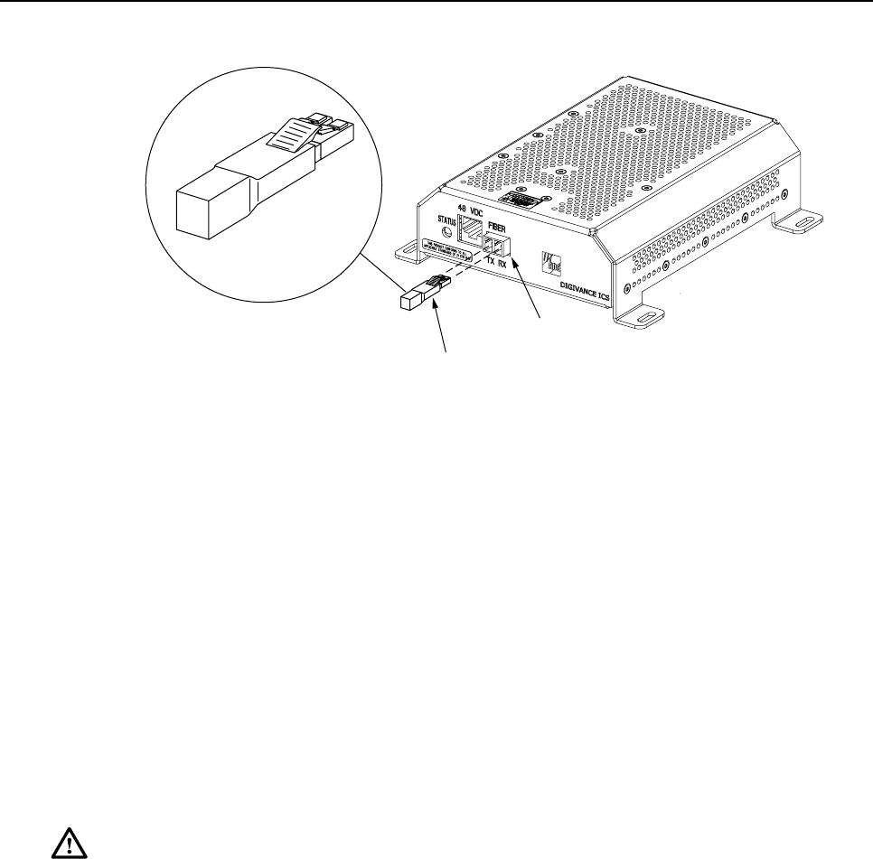
ADCP-75-110 • Issue 2B • July 2001
Page 52
©2001, ADC Telecommunications, Inc.
16769-A
OPTICAL LOOPBACK
CONNECTION DETAIL
OPTICAL
TRANSCEIVER
OPTICAL
LOOPBACK
Figure 26. DRU Loopback Test
21. At the DHU or supporting DEU, place the PORT ON/OFF switch in the OFF position
(press O).
22. Remove the loopback and reconnect the optical fiber connectors (remove dust caps) to
the DRU optical port or remote DEU host port.
23. At the DHU or supporting DEU, place the PORT ON/OFF switch in the ON position
(press I).
24. Verify that the PORT OK/NOK LED turns green.
5.4.2 Optical Loss Test Procedure
Abreak in an optical fiber or a fault with the optical connector will interrupt communications
between linked components. Use the following procedure to isolate aproblem with an optical
fiber or optical connector:
Danger:This equipment uses aClass 1Laser according to FDA/CDRH rules. Laser radiation
can seriously damage the retina of the eye. Do not look into the ends of any optical fiber. Do
not look directly into the optical transceiver of any digital unit or exposure to laser radiation
may result. An optical power meter should be used to verify active fibers. Aprotective cap or
hood MUST be immediately placed over any radiating transceiver or optical fiber connector
to avoid the potential of dangerous amounts of radiation exposure. This practice also prevents
dirt particles from entering the transceiver or connector.
1. Put on the IR filtering safety glasses.
2. At the DHU or supporting DEU, place the PORT ON/OFF switch for the fiber link to be
tested in the OFF position (press O)if not already off.
3. Disconnect the optical connectors at the DHU or supporting DEU and at the
corresponding DRU or remote DEU.
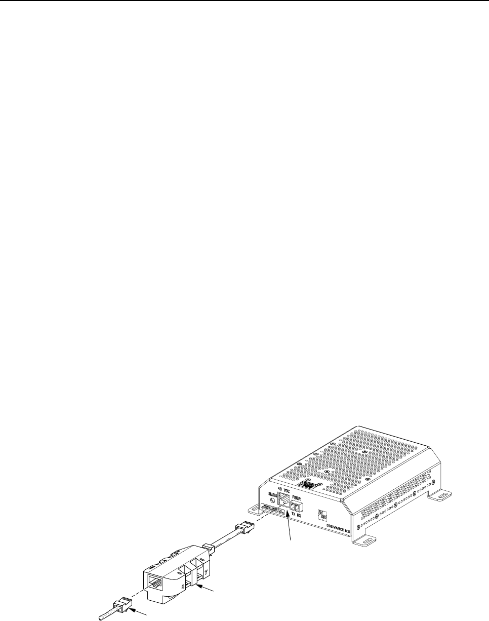
ADCP-75-110 • Issue 2B • July 2001
Page 53
©2001, ADC Telecommunications, Inc.
4. Inspect the optical connectors. Verify that each connector is clean and that no scratches
or imperfections are visible on the fiber end. Clean and polish the optical connector if
necessary.
5. Connect a laser light source to one end of the first optical fiber and an optical power
meter to the other end.
6. Verify that the power loss is within specifications (8 dB loss) for the length of the fiber
installed. If the power loss is not within specifications, repair or replace the optical fiber
and/or connector per local practice.
7. Repeat steps 5and 6for the second optical fiber.
8. Reconnect the optical connectors at the DHU or supporting DEU and the corresponding
DRU or remote DEU.
9. At the DHU or supporting DEU, place the PORT ON/OFF switch for the fiber link that
was tested in the ON position (press I).
5.4.3 DC Power Test Procedure
The DRU is powered by 34–48 Vdc power which is supplied through the RJ-45 connector.
Power to the DRU may be supplied by the DHU, DEU, or by a 120 Vac to 48 Vdc power
converter (available separately as an accessory item) plugged into a properly grounded 120
Vac outlet. Use the following procedure to test the DC power cable:
1. Disconnect the DC power cable from the DRU.
2. Connect the RJ-45 circuit access tool to the DRU as shown in Figure 27.
3. Connect the DC power cable to the RJ-45 circuit access tool (see Figure 27).
POWER
PORT
POWER
CONNECTOR
RJ-45 CIRCUIT
ACCESS TOOL
16205-A
Figure 27. Connect RJ-45 Circuit Access Tool
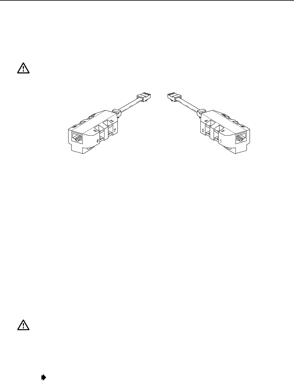
ADCP-75-110 • Issue 2B • July 2001
Page 54
©2001, ADC Telecommunications, Inc.
4. Using aDC voltmeter, verify that the DC voltage level is between 34 and 48 Vdc
between any set of positive and negative (+/-) terminals at the RJ-45 circuit access tool
as shown in Figure 28. Due to source current limiting at the DHU or DEU, low voltage
can mean excess wire resistance, low source voltage, or excess remote current.
Warning:The DRU uses 48 Vdc power. To avoid electric shock or burns, use extreme care
when working near exposed terminals or uninsulated cables. Be careful not to touch exposed
terminals or to cause ashort between terminals when checking voltage levels.
16206-A
TEST POINTS
(+) (-) TEST POINTS
(+) (-)
5 6
7 8 1 2
3 4
Figure 28. RJ-45 Circuit Access Tool Pin/Wire Designations
5. Disconnect RJ-45 circuit access tool from the DRU.
6. Use the DC voltmeter to check for open pin connections by checking for voltage between
the +/– pairs on the RJ-45 circuit access tool (see Figure 28).
7. Disconnect the DC power cable from the RJ-45 circuit access tool.
8. Re-connect DC power cable to the DRU.
5.5 DHU or DEU Fan Replacement Procedure
It is recommended that the fans (catalog #DGVI-100000FAN) be replaced every five years.
Replacement of afan requires that the DHU or DEU be turned off for ashort period of time. This
will drop all existing calls, cause atemporary loss of service, and generate amajor alarm. Use the
following procedure to replace the cooling fans within the DHU or the DEU:
1. Before touching the DHU or DEU or handling afan, slip on an Electro-Static Discharge
(ESD) wrist strap and connect the ground wire to an earth ground source. Wear the ESD
wrist strap while completing each section of the fan installation procedure.
Warning:Electronic components can be damaged by static electrical discharge. To prevent
ESD damage, always wear an ESD wrist strap when working on the DHU or DEU and when
handling electronic components.
2. Observe the fans (located on right side of enclosure) to determine which fan requires
replacement. The faulty fan may be stopped, running at areduced speed, or the fan
bearing may be noisy.
Note:Because the Mean Time Between Failures (MBTF) is the same for both fans, it may be
more efficient to replace both fans at the same time.
3. Notify the NOC or alarm monitoring system operator that the system is going offline.
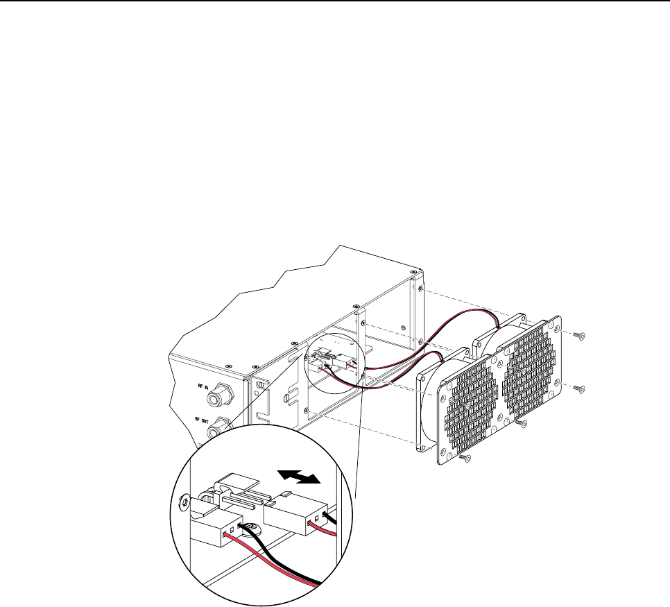
ADCP-75-110 • Issue 2B • July 2001
Page 55
©2001, ADC Telecommunications, Inc.
4. Place the DHU or DEU AC power On/Off switch (see Figure 3 or Figure 7) in the OFF
position (press O).
5. Remove the six flat-head screws (requires TORX screwdriver with T15 bit) that secure the
fan/grill assembly to the side of the enclosure as shown in Figure 29 and save for reuse.
6. Carefully withdraw the fan/grill assembly from the enclosure until the wiring harness is
exposed and the connectors are accessible.
7. Lift the small latch on each wiring harness connector (see Figure 29) and carefully
unplug each connector from the circuit board connector.
16172-B
Figure 29. Fan/Grill Assembly Removal
8. Remove the four plastic rivets that secure the faulty fan to the grill by pushing outward
on rivet center post until the rivet can be withdrawn from the grill as shown in Figure 30.
9. Remove the faulty fan(s) from the grill and then locate the replacement fan(s).
10. Use the rivets removed in step 8to secure the replacement fan to the grill. Orient the fan so the
wiring harness is on the top and the arrow on the fan housing faces into the enclosure.
11. Connect the two wiring harness connectors to the circuit board connectors.
12. Secure the fan/grill assembly to the side of the enclosure (see Figure 29) using the six
flat-head screws removed in step 5.
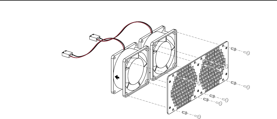
ADCP-75-110 • Issue 2B • July 2001
Page 56
©2001, ADC Telecommunications, Inc.
16173-B
Figure 30. Removing Fan From Grill
13. Place the DHU or DEU AC power On/Off switch in the ON position (press I).
14. Verify that the fans run properly following power up.
15. Notify the NOC or alarm monitoring system operator that the system is going back
online.

ADCP-75-110 • Issue 2B • July 2001
Page 57
©2001, ADC Telecommunications, Inc.
6 GENERAL INFORMATION
6.1 Warranty/Software
The Product and Software warranty policy and warranty period for all ADC products is
published in ADC’s Warranty/Software Handbook. Contact the Broadband Connections
Group (BCG) Technical Assistance Center at 1-800-366-3891, extension 63475 (in U.S.A. or
Canada) or 952-946-3000 (outside U.S.A. and Canada) for warranty or software information
or for a copy of the Warranty/Software Handbook.
6.2 Software Service Agreement
ADC software service agreements for some ADC Products are available at anominal fee. Contact
the BCG Technical Assistance Center at 1-800-366-3891, extension 63475 (in U.S.A. or Canada)
or 952-946-3000 (outside U.S.A. and Canada) for software service agreement information.
6.3 Repair/Exchange Policy
All repairs of ADC Products must be done by ADC or an authorized representative. Any
attempt to repair or modify ADC Products without authorization from ADC voids the
warranty.
If amalfunction cannot be resolved by the normal troubleshooting procedures, contact BCG
Technical Assistance Center at 1-800-366-3891, extension 63475 (in U.S.A. or Canada) or
952-946-3000 (outside U.S.A. and Canada). A telephone consultation can sometimes resolve a
problem without the need to repair or replace the ADC Product.
If, during atelephone consultation, ADC determines the ADC Product needs repair, ADC will
authorize the return of the affected Product for repair and provide aReturn Material
Authorization number and complete shipping instructions. If time is critical, ADC can arrange
to ship the replacement Product immediately. In all cases, the defective Product must be
carefully packed and returned to ADC.
6.4 Repair Charges
If the defect and the necessary repairs are covered by the warranty, and the applicable warranty
period has not expired, the Buyer’s only payment obligation is to pay the shipping cost to
return the defective Product. ADC will repair or replace the Product at no charge and pay the
return shipping charges.
Otherwise, ADC will charge apercentage of the current Customer Product price for the repair
or NTF (No Trouble Found). If an advance replacement is requested, the full price of a new
unit will be charged initially. Upon receipt of the defective Product, ADC will credit Buyer
with 20 percent of full price charged for any Product to be Out-of-Warranty. Products must be
returned within (30) days to be eligible for any advance replacement credit. If repairs
necessitate avisit by an ADC representative, ADC will charge the current price of a field visit
plus round trip transportation charges from Minneapolis to the Buyer’s site.

ADCP-75-110 • Issue 2B • July 2001
Page 58
©2001, ADC Telecommunications, Inc.
6.5 Replacement/Spare Products
Replacement parts, including, but not limited to, button caps and lenses, lamps, fuses, and
patch cords, are available from ADC on a special order basis. Contact BCG Technical
Assistance Center at 1-800-366-3891, extension 63475 (in U.S.A. or Canada) or 952-946-
3475 (outside U.S.A. and Canada) for additional information.
Spare Products and accessories can be purchased from ADC. Contact Sales Administration at
1-800-366-3891, extension 63000 (in U.S.A. or Canada) or 952-946-3000 (outside U.S.A. and
Canada) for aprice quote and to place your order.
6.6 Returned Material
Contact the ADC Product Return Department at 1-800-366-3891, extension 63748 (in U.S.A.
or Canada) or 952-946-3748 (outside U.S.A. and Canada) to obtain aReturn Material
Authorization number prior to returning an ADC Product.
All returned Products must have a Return Material Authorization (RMA) number clearly
marked on the outside of the package. The Return Material Authorization number is valid for
90 days from authorization.
6.7 Customer Information and Assistance
For customers wanting information on ADC products or help in using them, ADC offers the
services listed below. To obtain any of these services by telephone, first dial the central ADC
telephone number, then dial the extension provided below.
The central number for calls originating in the U.S.A. or Canada is 1-800-366-3891.For calls
originating outside the U.S.A. or Canada, dial country code “1” then dial 952-946-3000.
Sales Assistance
Extension 63000 • Quotation Proposals
•Ordering and Delivery
•General Product Information
Systems Integration
Extension 63000 •Complete Solutions (from Concept to Installation)
•Network Design and Integration Testing
•System Turn-Up and Testing
•Network Monitoring (Upstream or Downstream)
•Power Monitoring and Remote Surveillance
•Service/Maintenance Agreements
•Systems Operation
BCG Technical Assistance
Center
Extension 63475
E-Mail: bcg_tac@adc.com
•Technical Information
•System/Network Configuration
• Product Specification and Application
• Training (Product-Specific)
•Installation and Operation Assistance
• Troubleshooting and Repair
Product Return Department
Extension 63748
E-Mail: repair&return@adc.com
•ADC Return Authorization number and instructions
must be obtained before returning products.
Product information may also be obtained using the ADC web site at www.adc.com or by
writing ADC Telecommunications, Inc., P.O. Box 1101, Minneapolis, MN 55440-1101,
U.S.A.

ADCP-75-110 • Issue 2B • July 2001
Page 59
Contents herein are current as of the date of publication. ADC reserves the right to change the contents without prior notice. In no
event shall ADC be liable for any damages resulting from loss of data, loss of use, or loss of profits and ADC further
disclaims any and all liability for indirect, incidental, special, consequential or other similar damages. This disclaimer of
liability applies to all products, publications and services during and after the warranty period.
This publication may be verified at any time by contacting ADC’s Technical Assistance Center at 1-800-366-3891, extension
63475 (in U.S.A. or Canada) or 952-946-3475 (outside U.S.A. and Canada), or by e-mail to bcg_tac@adc.com.
©2001, ADC Telecommunications, Inc.
All Rights Reserved
Printed in U.S.A.