ADC Telecommunications F0064-111 InterReach® Fusion Remote Access Unit User Manual 2
ADC Telecommunications Inc. InterReach® Fusion Remote Access Unit 2
Contents
- 1. User manual 1
- 2. User manual 2
User manual 2
Document Title: WiMAX Gen 1 Spécification
REV Page
Rev 3 1 of 4
Filename: WiMAX Gen1
System Specification
Rev3.doc
When printed or copied, document is for REFERENCE ONLY as of,
03/07/08
LGC Wireless Confidential
1 Purpose
Purpose of this document is to list WiMAX Gen1 System Specifications.
2 Scope
This specification establishes the performance requirements for the WiMAX distributed antenna
system (DAS).
3 Responsibility
LGC Wireless is responsible for maintaining this document.
4 System Level Specification
4.1 Operating Frequencies
WiMAX Gen1 will have two frequency bands. This will allow customer to run Band 1 as main band and
Band 2 as MIMO. Second, it allows customer to run two independent bands for example one could be
sector 1 and other could be sector 2 with same or different frequency.
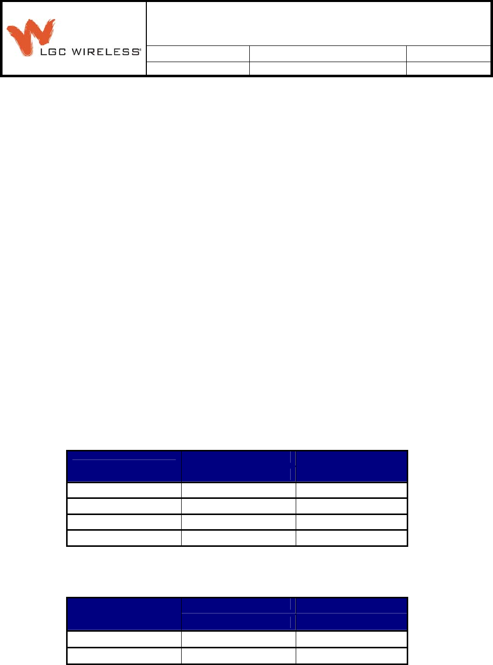
4.1.1 WiMAX Frequency Band 1:
WiMAX Band 1 has four sub bands that cover Complete WiMAX band from 2496-2690MHz in 60MHz sub
bands.
These tables might change based on marketing requirements.
Downlink Uplink
Band RF Passband (MHz) RF Passband (MHz)
WiMAX B1 2496 - 2556 2496 - 2556
WiMAX B2 2546 - 2606 2546 - 2606
WiMAX B3 2596 - 2656 2596 - 2656
WiMAX B4 2630 - 2690 2630 - 2690
4.1.2 WiMAX Frequency Band 2:
WiMAX Band 2 has four sub bands that cover Complete WiMAX band from 2496-2690MHz in 60MHz
sub bands.
Downlink Uplink
Band RF Passband (MHz) RF Passband (MHz)
WiMAX B1 2496 - 2556 2496 - 2556
WiMAX B2 2546 - 2606 2546 - 2606
Document Title: WiMAX Gen 1 Spécification
REV Page
Rev 3 2 of 4
Filename: WiMAX Gen1
System Specification
Rev3.doc
When printed or copied, document is for REFERENCE ONLY as of,
03/07/08
LGC Wireless Confidential
WiMAX B3 2596 - 2656 2596 - 2656
WiMAX B4 2630 - 2690 2630 - 2690
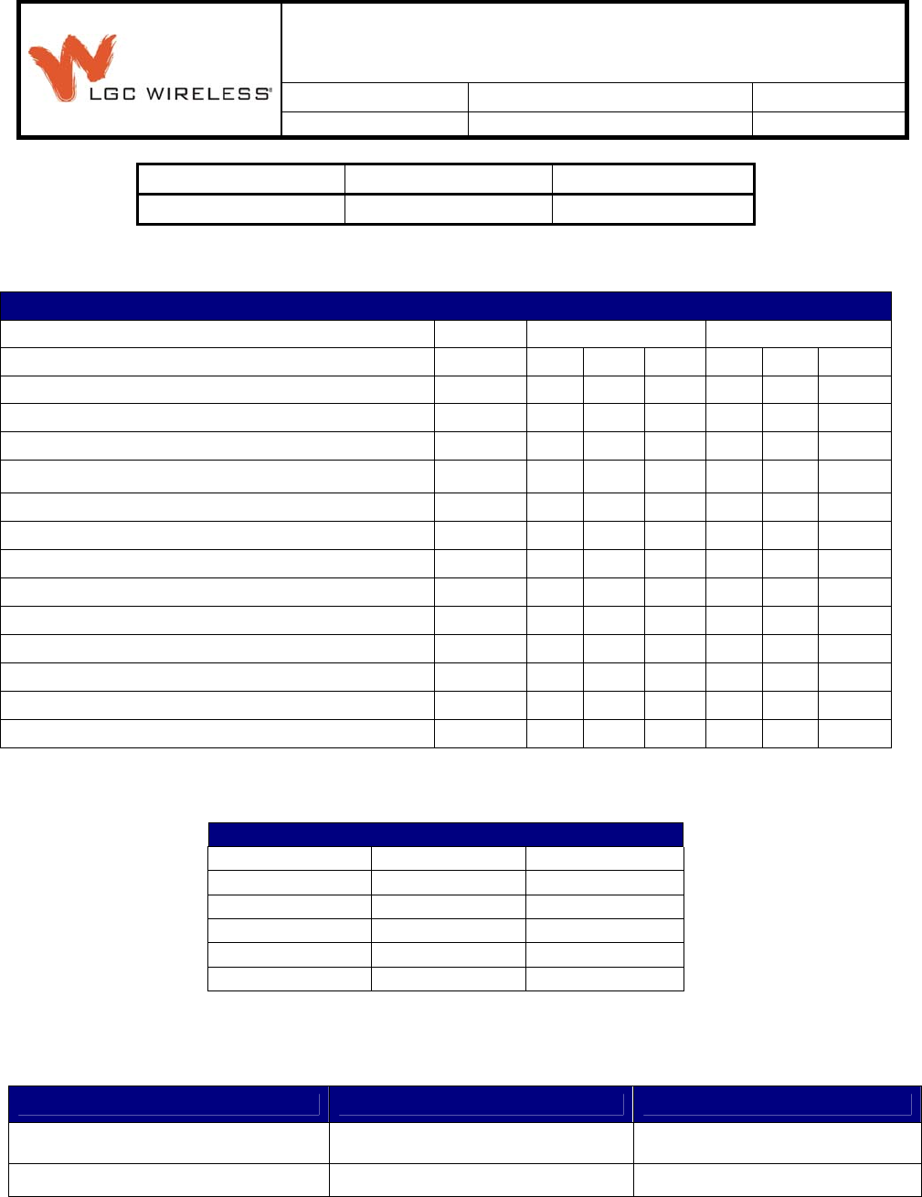
4.2 RF Specifications
RF End-to-End Performance
Downlink Uplink
Parameter Units Min Typ Max Min Typ Max
Average System Gain dB 15 15
System Gain Ripple dB 3.0 4.5 3.0 4.5
Output IP3 (SMF) dBm 33 38
Input IP3 (SMF) dBm -10 -5
Output P1dB dBm 25 28
NF 1-1 dB 11 16
NF 1-8 dB 17 21
NF 1- 4 – 32 dB 23 28
Output Noise Floor (SMF) dBm/Hz -100
UL Limiter Level (referenced to input) dBm -33
DL Limiter Level (referenced to output) for EPCS dBm 27
Out-of-Band Spurious Output Levels (Non LO) dBm -13 -13
Passband Spurious Output Levels (Non LO) dBm -36 -85 -75
4.2.1 System Phase Noise Performance
Phase Noise Performance Above 1GHz
Offset (kHz) Typ (dBc/Hz) Max (dBc/Hz)
0.1 60 57
1 73 68.5
10 83 78
30 96.5 92
100 108 104
5 Environmental Specifications:
Parameter Main Hub and Expansion Hub Remote Access Unit
Operating Temperature 0° to +45°C (+32° to +113°F) –25° to +45°C (–13° to +113°F)
Non-operating Temperature –20° to +85°C (–4° to +185°F) –25° to +85°C (–13° to +185°F)
Document Title: WiMAX Gen 1 Spécification
REV Page
Rev 3 3 of 4
Filename: WiMAX Gen1
System Specification
Rev3.doc
When printed or copied, document is for REFERENCE ONLY as of,
03/07/08
LGC Wireless Confidential
Operating Humidity; non-condensing 5% to 95% 5% to 95%
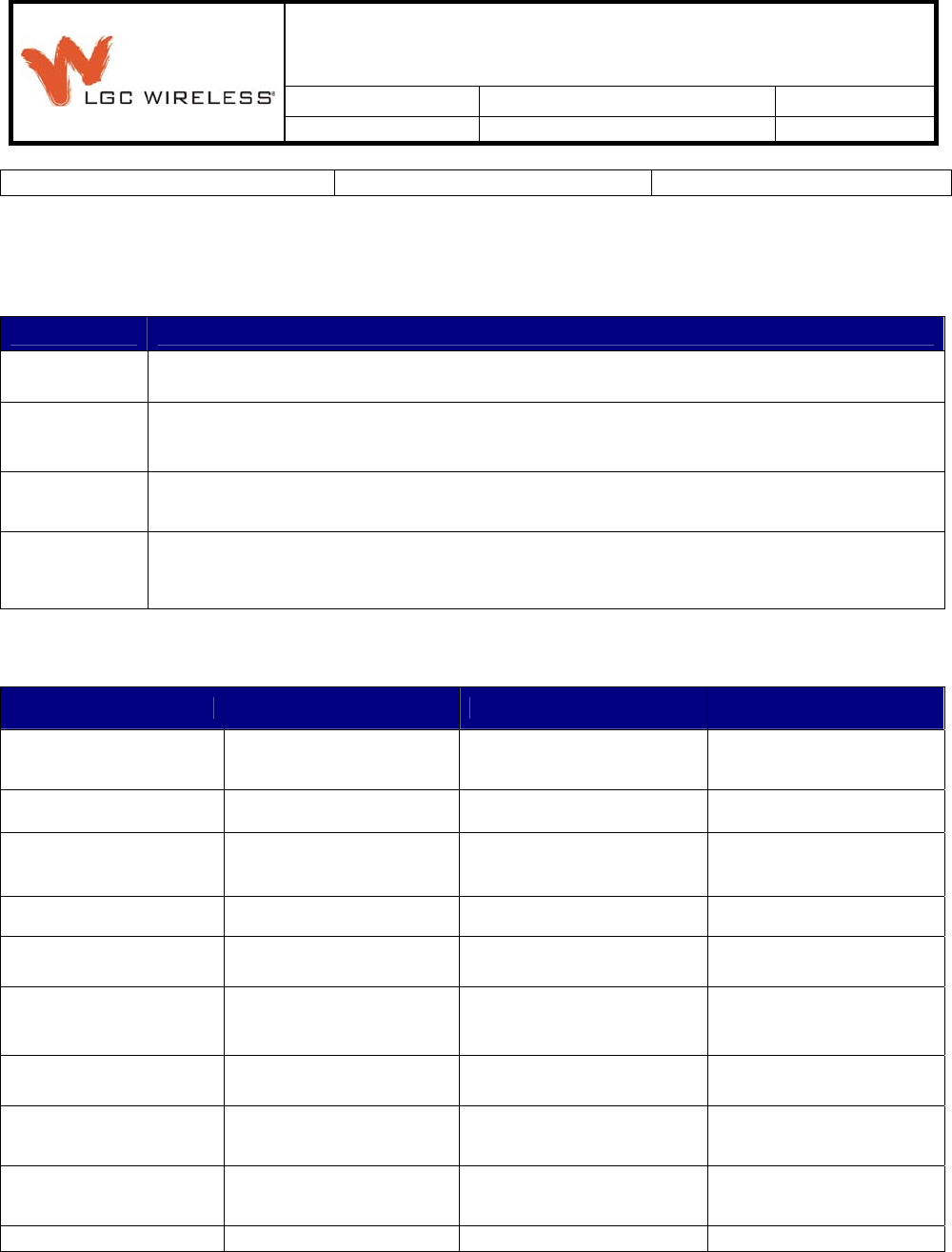
6 Cabling Specifications:
Parameter Specifications
Optical Fiber These specifications assume that the fiber optic cable, single-mode, is Corning with SC/APC connectors.
Optical Power
Budget Uplink and Downlink Maximum: 3 dB Optical power budget between Main Hub and Expansion Hub
CATV The specifications in this document assume that CATV RG-59 cable is CommScope 2065V, CATV RG-6 cable
is CommScope 2279V, and CATV RG-11 cable in CommScope 2293K or equivalent, with 75 ohm F
connectors.
CATV Lengths Minimum: 135 meters Maximum with RG-59
Maximum: 140 meters Maximum with RG-6
Maximum: 235 meters Maximum with RG-11
7 Physical Specifications:
Parameter Main Hub Expansion Hub Remote Access Unit
IF/RF Connectors 4 N, female (50 ohms), 1
Downlink / Uplink pair per
MIMO Channel
8 F, female
(CATV -75 ohms)
1 F, female (CATV - 75
ohms) 1 N, female (antenna
- 50 ohms)
External Alarm Connector
(contact closure) 1 9-pin D-sub, female — —
ADMIN/LAN Interface
Connector
1 RJ-45, female 1 9-pin D-
sub, male for optional
modem
1 RJ-45, female 1 9-pin D-
sub, male —
Fiber Connectors 4 Pair, SC/APC 1 Pair, SC/APC —
AC Power (Volts) Rating: 100-240V AC, 1A,
50–60 Hz Rating: 100-240V AC, 6A,
50–60 Hz 54V DC (from the E Hub)
Operating Range: 90–132V
AC/170–250V AC auto-
ranging
Operating Range: 90–132V
AC/170–250V AC auto-
ranging
DC Power (Volts) Rating/Operating Range:
38-64V DC, 2.5A Rating/Operating Range:
38-64V DC, 14A —
Power Consumption (W) 30 4 RAUs: 240 typical, 310
max. 8 RAUs: 400 typical,
530 max. —
Enclosure Dimensions
(height ×width ×depth)
89 mm × 438 mm × 381
mm (3.5 in. × 17.25 in. × 15
in.) 2U
89 mm × 438 mm × 381 mm
(3.5 in. × 17.25 in. × 15 in.)
2U
54 mm × 286 mm × 281 mm
(2.13 in. × 11.25 in. × 11.13
in.)
Weight < 5.5 kg (< 12 lb) < 6.6 kg (< 14.5 lb) < 2.1 kg (< 4.6 lb)
Document Title: WiMAX Gen 1 Spécification
REV Page
Rev 3 4 of 4
Filename: WiMAX Gen1
System Specification
Rev3.doc
When printed or copied, document is for REFERENCE ONLY as of,
03/07/08
LGC Wireless Confidential
Note Section 8 and 9 are for internal use only. They are for ATE configuration.
8 Main Hub TDD Requirements:
TDD Duplex port or Simplex ports will be configured in manufacturing based on
customer requirements.
8.1 MH TDD threshold configuration:
Main Hub threshold is configured at ATE. Each band and each Sub Band have different threshold and
memory location.
MH will switch to Downlink at input power of -10dBm. This is configured at ATE with 0dB System gain.
After setting MH gain and calibration threshold, ATE will inject -10dBm signal into MH and measure
detector threshold through A/D and program it into assigned memory location. ATE will measure and
program this value into each sub band it tests.
These steps are repeated for both bands.
9 RAU TDD Threshold Requirements:
9.1 RAU Threshold Configuration
RAU Threshold is set after RAU configuration is done. Each band have different threshold, and each sub
band has different threshold.
Band 1 setup: RAU Output power is set to -10dBm and Band 1 Downlink Burst Detector output is
measured through A/D and programmed in assigned memory location. Firmware uses this location for
Comparator threshold. These steps are repeated for Band 2.
10 RAU and MH Unit
RAU need to be configured to calibrated Pout of 5dBm from RAU.
MH need to be configured to +5dBm input Power with 0dB system gain.
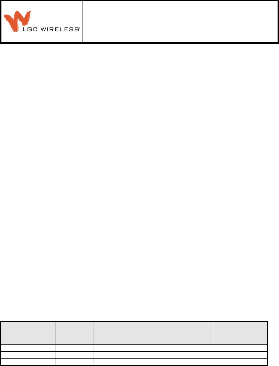
11 Change History:
Rev
ECO
NO.
Date
Description of Change
Change By
2 1/3/08 Add Section 8 and 9 TDD Threshold. Baljit Singh
3 2/14/08 Added section 10 Baljit Singh