ADC Telecommunications F0689-011 InterReach Fusion 700 MHz (Upper C) , AWS MIMO HP User Manual FusionWideband IOR Issue7 Pages 128 240
ADC Telecommunications Inc. InterReach Fusion 700 MHz (Upper C) , AWS MIMO HP FusionWideband IOR Issue7 Pages 128 240
Contents
- 1. NOOF0689011 User Manual Part 1
- 2. NOOF0689011 User Manual Part 2
NOOF0689011 User Manual Part 2
Installing Expansion Hubs
InterReach Fusion Wideband Installation, Operation, and Reference Manual Page 129
D-620616-0-20 Rev H • TECP-77-044 Issue 7 • May 2013 © 2013 TE Connectivity Ltd.
3
Ǥȋ͵ǤȌ
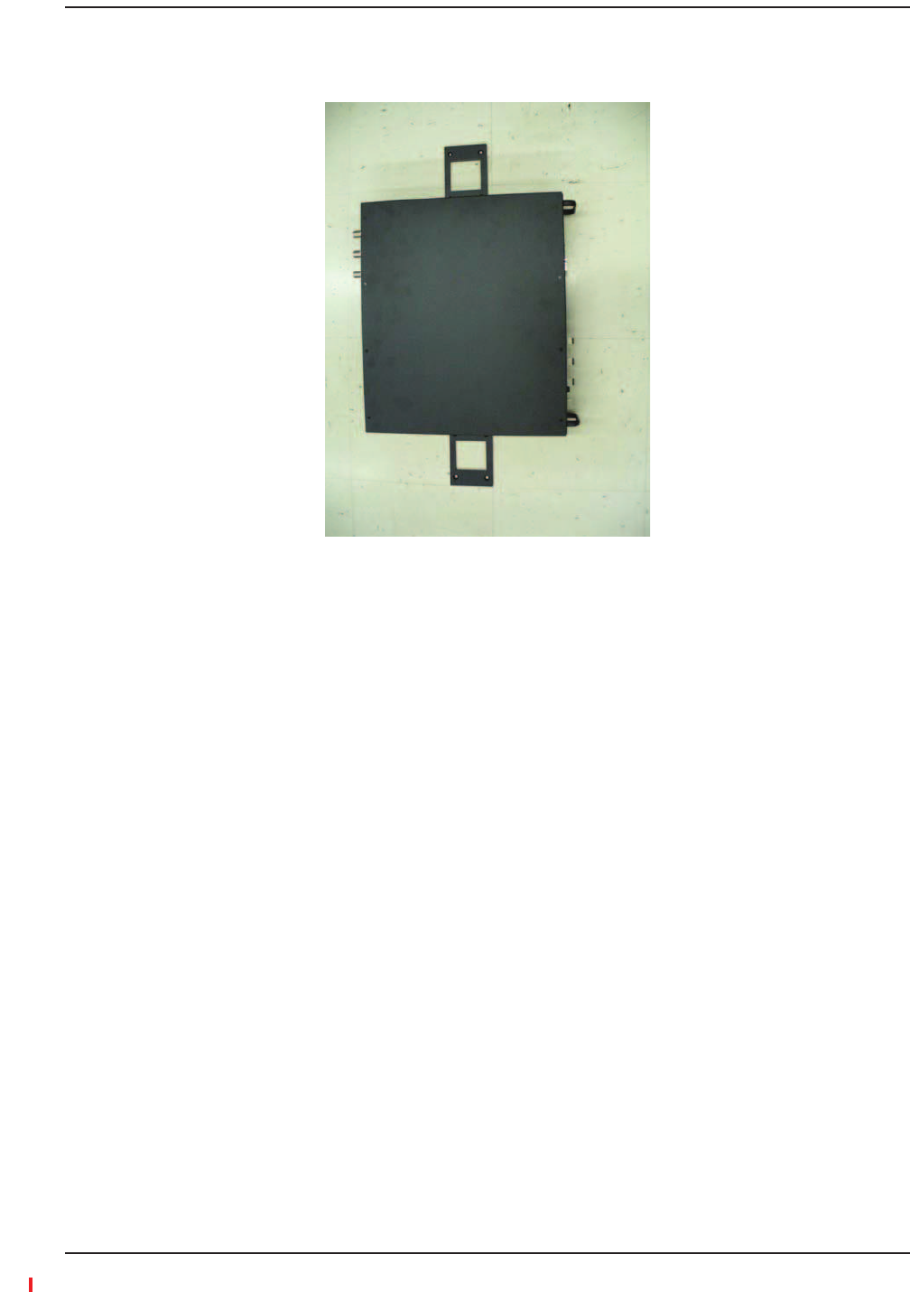
Figure37.Installing Directly to the Wall
4Ǥ
ǡ
Ǥ
1DzdzǦͳͺǤ
2
Ǥ
ǦǡǤ
Ǧǣ
•POWERUL STATUSǤ
•ǡUL STATUS
Ǥ
•E-HUB STATUSDL STATUS Ǥ
•Ǥ
3InstallinganOptionalCableManagerintheRack
3PoweringontheExpansionHub

Installing Fusion Wideband
Page 130 InterReach Fusion Wideband Installation, Operation, and Reference Manual
© 2013 TE Connectivity Ltd D-620616-0-20 Rev H • TECP-77-044 Issue 7 • May 2013
CAUTION! ObserveallFiberPortSafetyPrecautionslistedin“SafetyPrecautions”onpage109.
PreparingtheFiberCables
1͵ǤǦͲǤ
2ǡǡ
ǡ
Ǥ
3ǯȀȋǦȌǤUsinganyother
connectortypewillresultindegradedsystemperformanceandmaydamagethe
equipment.ȋȀǯȀǡ
DzdzͳͶͷǡ
ǤȌ
ConnectingtheFiberCables
12ǡǦǤ
ǡǦ
ȋȌǤ
IftheFiberJumperIsLabeledwith1or2
12DOWNLINKǤ
DL STATUSǤǡ
ǤǤ
21UPLINKǤ
UL STATUSǤʹͲ
Ǥ
ǯE-HUB STATUS
Ǥ
3UL STATUSE-HUB STATUSȀǡǢ
ʹͺͳʹǤ
3ConnectingtheFiberCablestotheExpansionHub

Installing Expansion Hubs
InterReach Fusion Wideband Installation, Operation, and Reference Manual Page 131
D-620616-0-20 Rev H • TECP-77-044 Issue 7 • May 2013 © 2013 TE Connectivity Ltd.
IftheFiberJumperIsColorͲCoded
1DzdzDOWNLINKǤ
DL STATUSǤǡ
ǤǤ
2DzdzUPLINKǤ
UL STATUSǤʹͲ
Ǥ
ǯE-HUB STATUS
Ǥ
3UL STATUSE-HUB STATUSȀǡǢ
ʹͺͳʹǤ
1Ǥ
ǦǤ
2
ȋȌǤ
3ǣ
•
•
•ȋȌ
4Ǥ
STATUS
Ǥ
5ȋǡȌǡ
ǦǤ
6Ǧ
Ǥ
3Connectingthe75OhmCATVCables

Installing Fusion Wideband
Page 132 InterReach Fusion Wideband Installation, Operation, and Reference Manual
© 2013 TE Connectivity Ltd D-620616-0-20 Rev H • TECP-77-044 Issue 7 • May 2013
•PORTȀǤ
Ǥ
•UL STATUSǤ
3TroubleshootingExpansionHubLEDsDuringInstallation
Table88.TroubleshootingExpansionHubLEDsDuringInstallation
During
Installation
LED State Action Impact
1Expansion Hub
power is On
and no RAUs
are connected
POWER Off Check AC power; make sure the
Expansion Hub power-on switch is
on; replace the Expansion Hub.
The Expansion Hub is not
powering on.
PORT LEDs are on but didn’t
blink through all
states.
Replace the Expansion Hub. The Microcontroller is not
resetting properly; flash
memory corrupted.
PORT Flashing Red
(6 PPM)
Port unusable; replace the
Expansion Hub when possible.
Current sensor fault; do not
use the port.
UL STATUS Red, after power-up
blink
Replace the Expansion Hub. The Expansion Hub laser is not
operational; no uplink between
the Expansion Hub and Main
Hub.
UL STATUS Red Check the Main Hub LEDs—refer to
Step 2 in Table 87 on page 126.
Use AdminBrowser to determine the
problem.
No communication with Main
Hub.
DL STATUS Red Check the downlink fiber for optical
power; verify that the cables are
connected to correct ports (that is,
uplink/downlink)
Check the Main Hub LEDs—refer to
Step 2 in Table 87 on page 126.
No downlink between the
Expansion Hub and Main Hub.
2Expansion Hub
power is On
and RAUs are
connected
PORT Off Check the CATV cable. Power is not getting to the
RAU.
PORT Flashing Red
(60 PPM)
Test the CATV cable. If the cable
tests OK, try another port. If the
second port’s LEDs are Red/Off,
replace the RAU. If the second RAU
doesn’t work; replace the Expansion
Hub.
Power levels to RAU are not
correct; communications are
not established.
If the second port works, flag
the first port as unusable;
replace EH when possible.
PORT Red Use AdminBrowser to determine the
problem.
RAU is off-line.

Installing RAUs
InterReach Fusion Wideband Installation, Operation, and Reference Manual Page 133
D-620616-0-20 Rev H • TECP-77-044 Issue 7 • May 2013 © 2013 TE Connectivity Ltd.
INSTALLINGRAUS
CAUTION! InstallRAUsinindoorlocationsonly.Donotconnectanantennathatisinstalledinanoutdoor
locationtoanRAU.Foroutdoorinstallations,aprotectiveenclosureisrequired.
NOTE: Thefollowingproceduresassumethatthesystemisnewfromthefactoryandthatithasnot
beenprogrammedwithbands.IfyouarereplacingcomponentsinapreͲinstalledsystemwith
eithernewunitsorunitsthatmayalreadybeprogrammed(forexample,reͲusingunitsfrom
anothersystem),referto“ReplacingFusionWidebandComponents”onpage175.
Ǥ
•ͺͲͲͺͷͲȀͳͻͲͲ
ͺͲͲͺͷͲǤDzͺͲͲȀͺͷͲ
dzͳ͵ͶǤ
•ǡǡǡǡǡ
ǡ
Ǥȋǡǡǡ
ȌͶ
͓ǤǤǤ
•ȋǡǡǡȌǤ
•ǣ
–ȋ͵ǤȌǤ
–Ǥ
–ȋȌ
Ǥ
ǯǤ
Location
Ǥǡ
Ǥ
3InstallingRAUs
3InstallingPassiveAntennas
Installing Fusion Wideband
Page 134 InterReach Fusion Wideband Installation, Operation, and Reference Manual
© 2013 TE Connectivity Ltd D-620616-0-20 Rev H • TECP-77-044 Issue 7 • May 2013
800/850MHzIsolationRequirements
ǡ
ǦǦǤǡǦ
Ǥǡ
Ǥ
Ǥ
ͺͲͲͻͲͲȋǣͺͷͳȂͺͻȀǣͺͲȂͺʹͶ
ǣͻ͵ͷȂͻͶͳȀǣͺͻȂͻͲʹȌǡͺͷͲ
ȋǣͺͻȂͺͻͶȀǣͺʹͶȂͺͶͻȌǤǡͺͲͲȀͻͲͲ
ͺͷͲǡȋȌȋ
ȌǤ͵ͺǡ
Ǥ
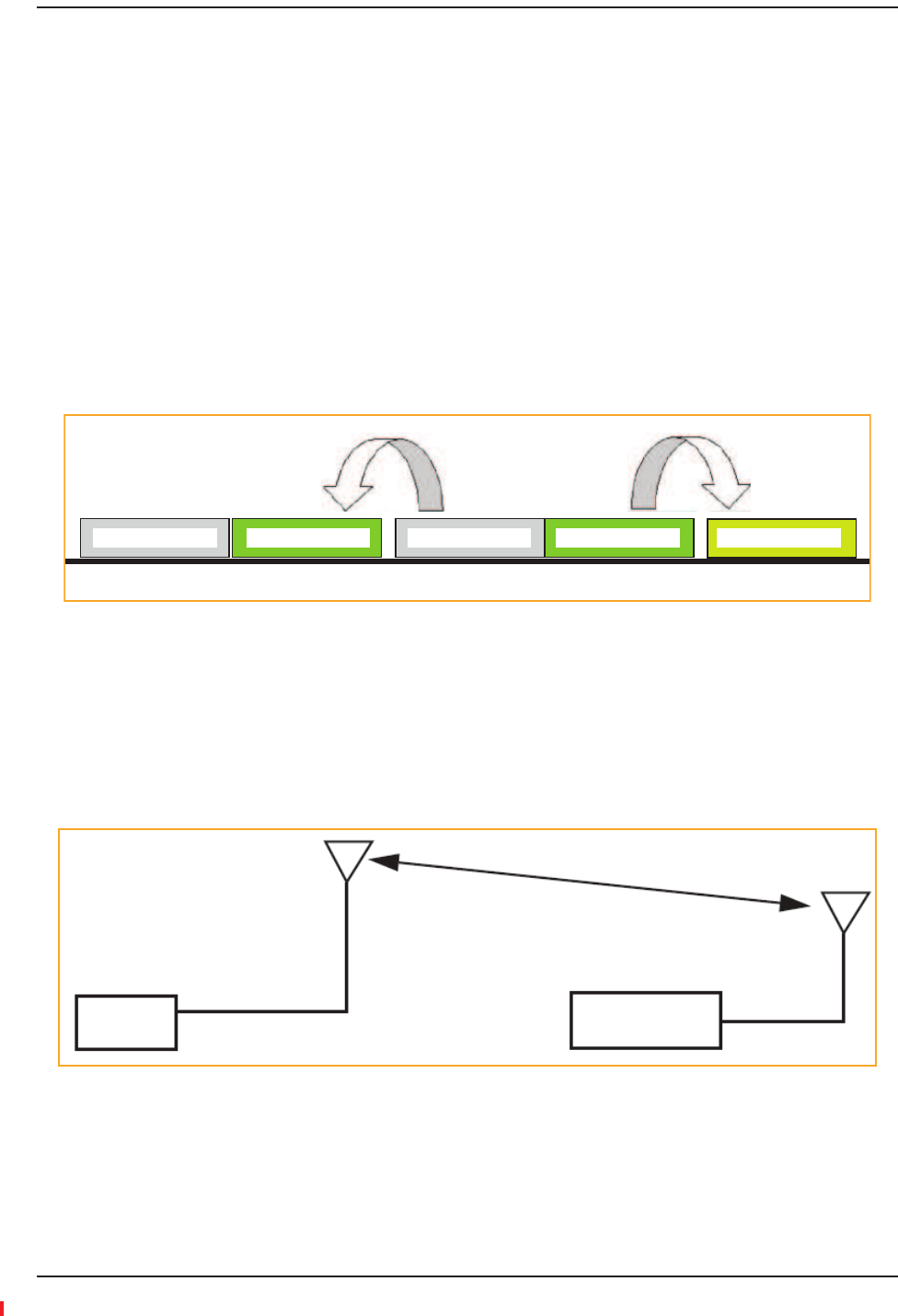
Figure38.800/850 MHz Spectrum
ǦȋȌ
ͺͲͲȀͻͲͲͺͷͲǦǦ
Ǥ
Ǥ
Figure39.Fusion Wideband 800/850/1900 MHz RAU Antenna Placement Guideline
824 849 851 869 894 896 - 902
800/iDEN Uplink 850 Cellular Uplink 800/iDEN Downlink 850 Cellular Downlink 900/iDEN Uplink
Band 1
800 MHz
Band 2/3
850/1900 MHz
>d

Installing RAUs
InterReach Fusion Wideband Installation, Operation, and Reference Manual Page 135
D-620616-0-20 Rev H • TECP-77-044 Issue 7 • May 2013 © 2013 TE Connectivity Ltd.
800MHziDENDownlinkand850MHzCellularUplink
ʹȋͺͷͳȂͺͶͻȌͺͲͲͺͷͲ
ǤǡͺͲͲ
ͺͷͲǤǡͺͲͲ
ͺͷͳͺͷͲ
ȋȌǤ
ǡǣ
•ǦͺͲͲδǦͻͲ
•ͺͲͲδȂ͵Ͳ
ȋͶǡǦǡȌǡ
ȋͳȌȂͻǤ
850MHzCellularDownlinkand900MHziDENUplink
ʹȋͺͻȂͺͻͶȌͺͷͲͻͲͲ
ǤǡͺͷͲ
ͻͲͲǤǡͺͷͲ
ͺͻͶͻͲͲ
Ǥ
ǡǣ
•ǦͺͷͲδǦͻͲ
•ͺͷͲδȂ͵Ͳ
ȋǡǦ
ǡȌǡȋʹȌͺǦͳͶǤ
ǦͺͷͳͻǦͳǦͺͲͻͲͳͻǦʹͺͳͶ
Ǥ
Ǧ
Ǥ
CAUTION! FirmlyhandͲtightentheNconnector–DONOToverͲtightentheconnector.
3ConnectingtheAntennatotheRAU

Installing Fusion Wideband
Page 136 InterReach Fusion Wideband Installation, Operation, and Reference Manual
© 2013 TE Connectivity Ltd D-620616-0-20 Rev H • TECP-77-044 Issue 7 • May 2013
1Ǥ
ǦǤ
2ͷǦ
ͷǤ
3ǣ
•
•
•ȋȌ
4Ǥ
Ǥ
ǡǤ
Ǧǣ
•LINK
Ǥ
•ALARM
ǡʹͲǡǤ
5ȋȌǢ
ǦǤ
6Ǧ
Ǥ
3ConnectingtheCATVCable

Installing RAUs
InterReach Fusion Wideband Installation, Operation, and Reference Manual Page 137
D-620616-0-20 Rev H • TECP-77-044 Issue 7 • May 2013 © 2013 TE Connectivity Ltd.
TroubleshootingUsingRAULEDsDuringInstallation
LINKͻͲǤALARM
Ǥ
Table89.TroubleshootingRAULEDsDuringInstallation
During
Installation
LED State Action Impact
The RAU is connected to
the Fusion Wideband
Expansion Hub, which is
powered on
LINK Off Check CATV cable. No power to the RAU.
ALARM Off
LINK Green • Check CATV cable
• Check the Main Hub LEDs—refer to
Step 2 in Table 87 on page 126.
• Use AdminBrowser to determine the
problem.
The RAU is off-line.
ALARM Red
LINK Red from
green, after
cables are
connected for
60 seconds
• Check CATV cable.
• Check the Hub LEDs.
• Use AdminBrowser to determine the
problem.
No communications between
the RAU and the Hub.
ALARM Red

Installing Fusion Wideband
Page 138 InterReach Fusion Wideband Installation, Operation, and Reference Manual
© 2013 TE Connectivity Ltd D-620616-0-20 Rev H • TECP-77-044 Issue 7 • May 2013
CONFIGURINGTHEFUSIONWIDEBANDSYSTEM
ǡ
Ǥ
Ǥ
ǡAdminBrowserUserManualȋǦʹͲͲǦͲǦʹͲȌǡ
ȀǤ
NOTE: Thefrequencybandsshouldautomaticallybesetonpowerupandthisstepshouldnotbe
required.
NOTE: CrossoverEthernetcablewithmaleconnectorsrequired.
NOTE: Thefollowingproceduresassumethatthesystemisnewfromthefactoryandthatithasnot
beenprogrammedwithbands.IfyouarereplacingcomponentsinapreͲinstalledsystemwith
eithernewunitsorunitsthatmayalreadybeprogrammed(forexample,reͲusingunitsfrom
anothersystem),referto“ReplacingFusionWidebandComponents”onpage175.
1Ǥ
CAUTION! MakesuretheHubisgroundedthroughthegroundlugontheACpowerandtheframeground
lugasrequired.ThewarrantydoesnotcoverdamagecausedwhenanungroundedHubis
poweredon.
2Ǥ
3Ǥ
4Ǥ
Ǥ
ȋȌǡǤSTATUS
ͻͲǤ
ǯ
Ǥ
ʹͲǤ
5ǦȀRJ-45 100-BASE-T
ǯǤ
3ConnectingthePCtotheMainHubtoRunAdminBrowser
Configuring the Fusion Wideband System
InterReach Fusion Wideband Installation, Operation, and Reference Manual Page 139
D-620616-0-20 Rev H • TECP-77-044 Issue 7 • May 2013 © 2013 TE Connectivity Ltd.
1ȀȀRJ-45
ǯǤ
2Ǥ
3ǣ
•ForWindows2000:
aǦMy Network Places
PropertiesǤ
bInternet Protocol (TCP/IP)
PropertiesǤ
Ǥ
•ForwindowsXP:
aStart>Settings>Network
Connections>LocalAreaConnectionǤ
Ǥ
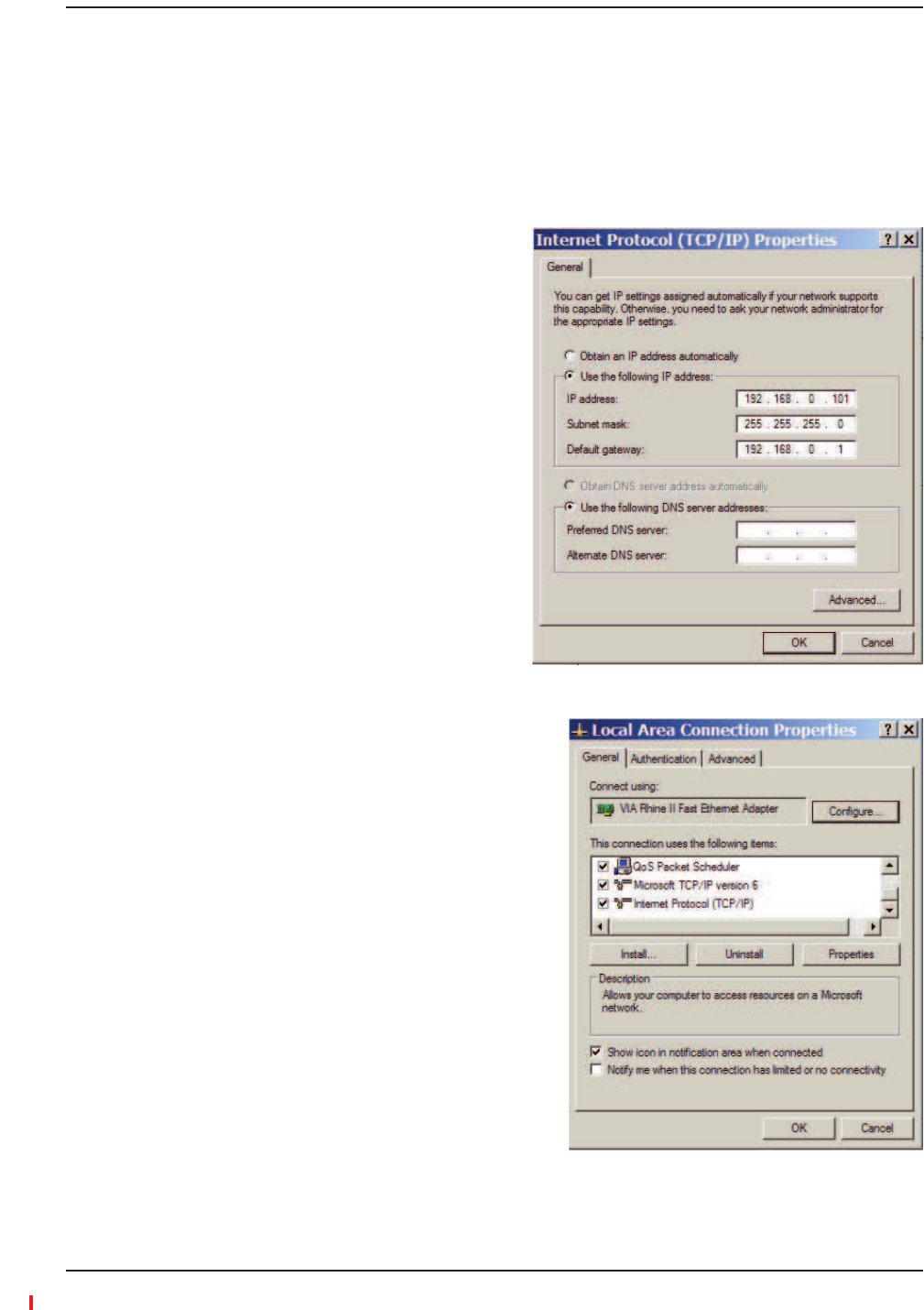
bThis connection uses the following
itemsǡInternet
Protocol (TCP/IP)PropertiesǤ
3ProgrammingtheMainHubUsingAdminBrowser
Installing Fusion Wideband
Page 140 InterReach Fusion Wideband Installation, Operation, and Reference Manual
© 2013 TE Connectivity Ltd D-620616-0-20 Rev H • TECP-77-044 Issue 7 • May 2013
4ǡǡǡǤ
ǦǤ
5Use the following IP addressǤ
6IP addressͳͻʹǤͳͺǤͲǤͳͲͳ
7Subnet maskʹͷͷǤʹͷͷǤʹͷͷǤͲ
8Default gateway ͳͻʹǤͳͺǤͲǤͳ
9OKǤǤǡYesǤ
UsingAdminBrowser
ǡǣ
1Ǥ
2ǣ
Https://192.168.0.100
3GoǤ
4ǡǣoperatorǡ
ǣpasswordǤ
5ǡǡ
ǣoperatorpasswordǤ
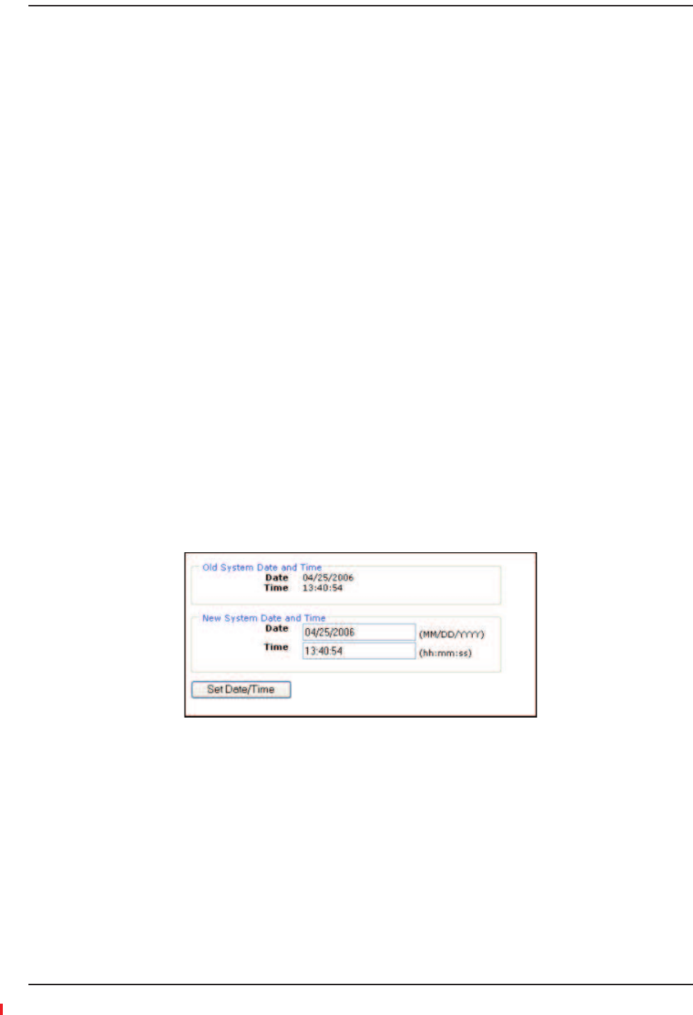
6SystemConfigurationSetDate/TimeǤ
Ǥ
7SetDate/TimeǤ
Ǥ

Configuring the Fusion Wideband System
InterReach Fusion Wideband Installation, Operation, and Reference Manual Page 141
D-620616-0-20 Rev H • TECP-77-044 Issue 7 • May 2013 © 2013 TE Connectivity Ltd.
8Install/ConfigureSystemǤ
Ǥ
9ǡLabelǤ
Ǥ
͵ʹǤ
FusionǡǤ
10 Ǥ
ǣ
•Ǥ
•Ǥ
•Ǥ
•Ǥ
ǡǦǦǤ
ǡ
ǢǡǤ
ȋȌ
Ǥ
ǡ
ǡǤ
Installing Fusion Wideband
Page 142 InterReach Fusion Wideband Installation, Operation, and Reference Manual
© 2013 TE Connectivity Ltd D-620616-0-20 Rev H • TECP-77-044 Issue 7 • May 2013
11
Ǥ
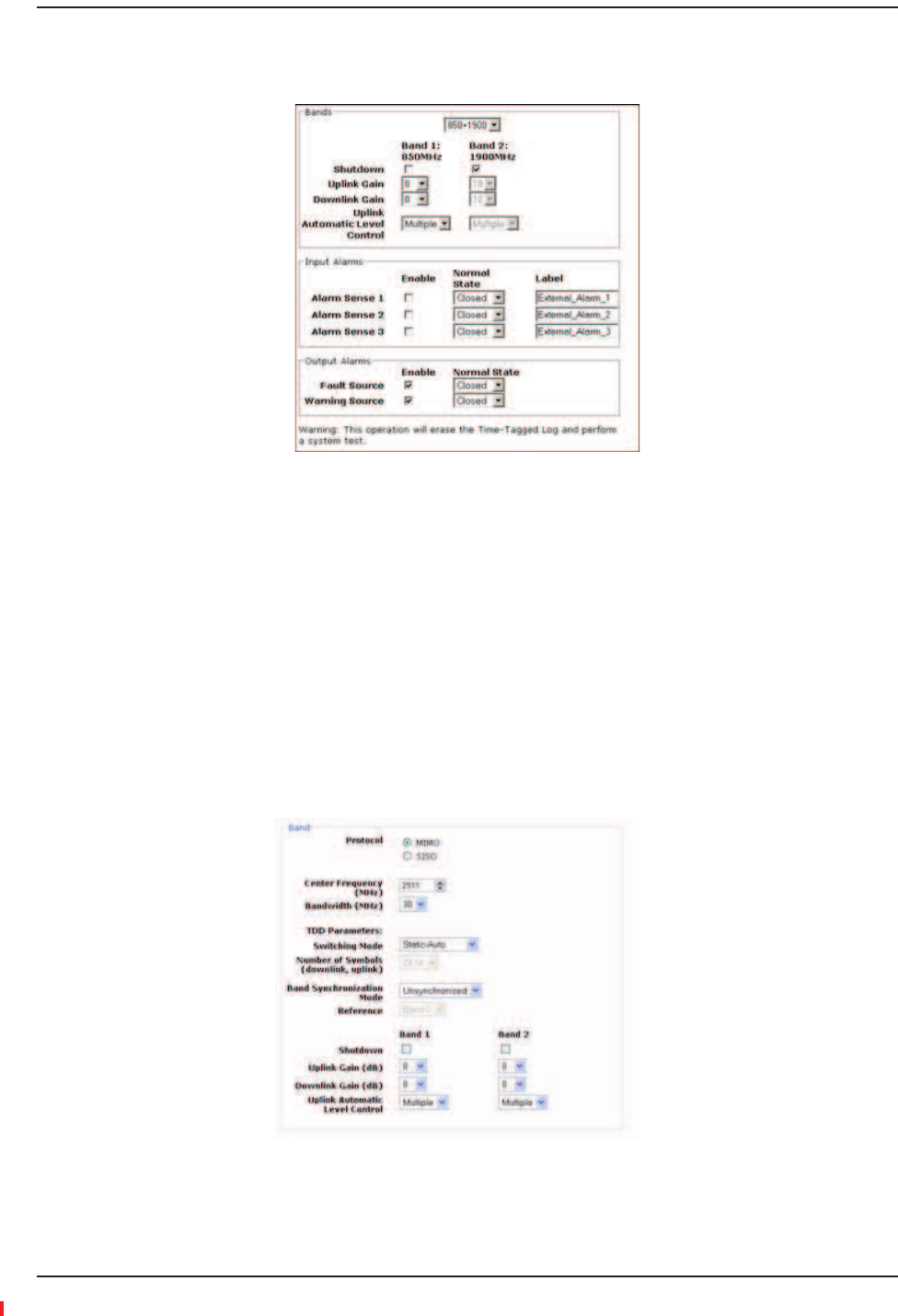
12 Bandsǡǣ
•Ǥ
Ǥ
•ǡShutdownǤ
Ǥ
•UplinkDownlinkǤ
ͳǤ
•UplinkAutomaticLevelControlSingleMultipleȋȌ
Ǥ
13 FORWiMAXINSTALLATIONSONLYǣ
Ǥ

Configuring the Fusion Wideband System
InterReach Fusion Wideband Installation, Operation, and Reference Manual Page 143
D-620616-0-20 Rev H • TECP-77-044 Issue 7 • May 2013 © 2013 TE Connectivity Ltd.
ǡǣ
•ǣ
ǣ
MIMOȋǦȌ
SISOȋǦȌǤDzdzǤ
•Ǥ
ͳʹǤ
NOTE: InMIMOmode,thefrequenciesarethesame.Thesystemcanbeconfiguredtosupport2ͲSISO
radios,oneperband,acrossany30MHzwithintheWiMAXband.
•ǦǤ
ǦǦǤǣ
–StaticǦSelected:ǤǦ
Ǥȋ
DzʹͻǡͳͺdzǤȌǡ
Ǥ
–StaticǦAuto:
ǡǤȋDzǦdzȌ
•ǦǤ
ǣ
–Synchronized:ǡ
Ǥǡ
Ǥ
–Unsynchronized:ǡ
ǤȋDzdzȌ
•Reference:Ǥ
•ǡǤ
Ǥ
•ǦǤ
ͳǤ
•ǦDzdz
DzdzǤȋDzǤdzȌ
14
Ǥ

Installing Fusion Wideband
Page 144 InterReach Fusion Wideband Installation, Operation, and Reference Manual
© 2013 TE Connectivity Ltd D-620616-0-20 Rev H • TECP-77-044 Issue 7 • May 2013
15 Input/OutputAlarmsǡǣ
•Ǥ
•ǦǤȋDzǤdz
•Ǥ
16 ǡInstall System
Ǥ
Ǣ
ǡǡǢǢǢ
Ǥǣ
ǡ
Ǥ
17 ȋǡȌǤ
CAUTION! DonotexceedthemaximuminputRFpower(1Watt)totheFusionWidebandMainHub.
ExceedingthelimitcouldcausepermanentdamagetotheHub.
CAUTION! OnlycarriersandtheirapprovedinstallersorTEͲauthorizedinstallersareallowedtoconnectto
theRFsource.SeriousdamagetotheequipmentcanoccurifitisoverͲdriven.
Ǥǡ
Ǥ
18 ȀǤ
NOTE: TEequipmentisdesignedtooperateinthelicensedfrequencybandsofmobileoperators.Inthe
USA,theEU,andmostcountriesthisequipmentmayonlybeusedbythelicensee,hisauthorized
agentsorthosewithwrittenauthorizationtodoso.Similarly,unauthorizeduseisillegal,and
subjectstheownertothecorrespondinglegalsanctionsofthenationaljurisdictioninvolved.
OwnershipofTEequipmentcarriesnoautomaticrightofuse.
Indicates that the band is correctly set on the Main Hub.
Indicates that the band is correctly set on the Expansion Hub.
Indicates that communications are OK.

Splicing Fiber Optic Cable
InterReach Fusion Wideband Installation, Operation, and Reference Manual Page 145
D-620616-0-20 Rev H • TECP-77-044 Issue 7 • May 2013 © 2013 TE Connectivity Ltd.
SPLICINGFIBEROPTICCABLE
ȀǤǡ
ǡȀǡǤ
ǣǦȋͶͲͳ͵Ǧ͵ȌǦ
ȋͶͲͳʹǦ͵ȌǤ
Ǥ
Ǥ
Ǥ
ǤȋͲǤͲͷȌ
ȋȌǤ
Ǥ
NOTE: Thefollowingproceduresassumethatthesystemisnewfromthefactoryandthatithasnot
beenprogrammedwithbands.IfyouarereplacingcomponentsinapreͲinstalledsystemwith
eithernewunitsorunitsthatmayalreadybeprogrammed(forexample,reͲusingunitsfrom
anothersystem),referto“ReplacingFusionWidebandComponents”onpage175.
OptionA:FusionWidebandSplicetheFiberͲOpticCabletotheSC/APCPigtail
1ȋǡǦ
ǦȌǤ
2Ȁ
Ǥ
3ǡ
ǡǡDzdzȂ
Ǥ
4
Ǥ
5ǦǤ
6ǯ
Ǥ
7ͶȀǤ
8Ǥ
9
ǯǤ
10
ͲǤͳͲǤ
11 Ǥ
3FusionWidebandSplicingofFiberandPigtail

Installing Fusion Wideband
Page 146 InterReach Fusion Wideband Installation, Operation, and Reference Manual
© 2013 TE Connectivity Ltd D-620616-0-20 Rev H • TECP-77-044 Issue 7 • May 2013
12 ǯǤ
13 Ǥ
14 ǡǡ
ǯǤ
15 ǡȀ
Ǥ
OptionB:FusionWidebandSplicetheFiberͲOpticCabletotheSC/APCPigtail
1ȋǡǦ
ǦȌǤ
2Ȁ
Ǥ
3ǡ
ǡǡDzdzȂ
Ǥ
4
Ǥ
5ǦǤ
6ǯ
Ǥ
7͵ȀǤ
8Ǥ
9
ǯǤ
10
ͲǤͳͲǤ
11 Ǥ
12 ǯǤ
13 Ǥ
14 ǡǡ
ǯǤ
15 ǡȀ
ȀǤ
16 ȀȀ
Ǥ
NOTE: Forinformationontroubleshooting,see“Maintenance,Troubleshooting,andTechnical
Assistance”onpage181.

Interfacing the Fusion Wideband Main Hub to an RF Source
InterReach Fusion Wideband Installation, Operation, and Reference Manual Page 147
D-620616-0-20 Rev H • TECP-77-044 Issue 7 • May 2013 © 2013 TE Connectivity Ltd.
INTERFACINGTHEFUSIONWIDEBANDMAINHUBTOANRFSOURCE
CAUTION! OnlyTEpersonnelorTEͲauthorizedinstallationpersonnelshouldconnecttheFusionWideband
MainHubtoitsBandassociatedbasestationorrepeater.Exceedingthemaximuminputpower
couldcausefailureoftheFusionWidebandMainHub(referto“RemoteAccessUnitConnectors”
onpage57formaximumpowerspecifications).Ifthemaximumcompositepoweristoohigh,
attenuationisrequired.
NOTE: Thefollowingproceduresassumethatthesystemisinstalledandhasbeenprogrammedwith
bands.
ConnectingaSingleFusionWidebandMainHubtoanRFSource
ǡͳǡʹǡ͵Ǥ
Ǥ
CAUTION! OnlyTEpersonnelorTEͲauthorizedinstallationpersonnelshouldconnecttheFusionWideband
MainHubtoabasestationorrepeater.Exceedingthemaximuminputpowercouldcausefailure
oftheFusionWidebandMainHub(referto“RemoteAccessUnitConnectors”onpage57for
maximumpowerspecifications).Ifthemaximumcompositepoweristoohigh,attenuationis
required.
CAUTION! TheUPLINKandDOWNLINK portscannothandleaDCpowerfeedfromthebasestation.IfDC
powerispresent,aDCblockmustbeusedorthehubmaybedamaged.
3ConnectingaFusionWidebandMainHubtoanInͲBuildingBTS
Installing Fusion Wideband
Page 148 InterReach Fusion Wideband Installation, Operation, and Reference Manual
© 2013 TE Connectivity Ltd D-620616-0-20 Rev H • TECP-77-044 Issue 7 • May 2013
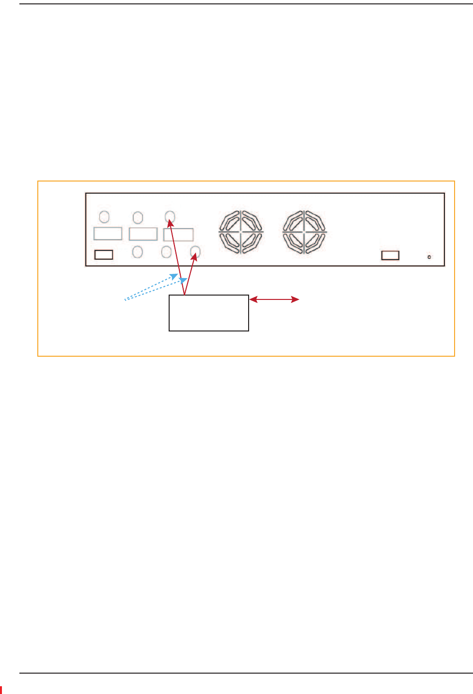
ConnectingaSimplexBaseStationtoaFusionWidebandMainHubRFBand
1ǦǦ
Ǥ
2ǦǦDOWNLINK
ͳǡʹǡ͵Ǥ
3ǦǦ
Ǥ
4ǦǦUPLINK
ͳǡʹǡ͵Ǥ
Figure40.Simplex Base Station to a Fusion Wideband Main Hub
Simplex
Base Station
Band 3
Band 1 Band 2 Band 3
UL1 UL2 UL3
Alarms
DL1 DL2 DL3
AC Power
N-male to N-male
coaxial cable
T1/E1 to
Mobile
Switching
Center
Insert attenuator
(if needed)
NOTE: This applies to Band 1, Band 2, and Band 3.
Interfacing the Fusion Wideband Main Hub to an RF Source
InterReach Fusion Wideband Installation, Operation, and Reference Manual Page 149
D-620616-0-20 Rev H • TECP-77-044 Issue 7 • May 2013 © 2013 TE Connectivity Ltd.
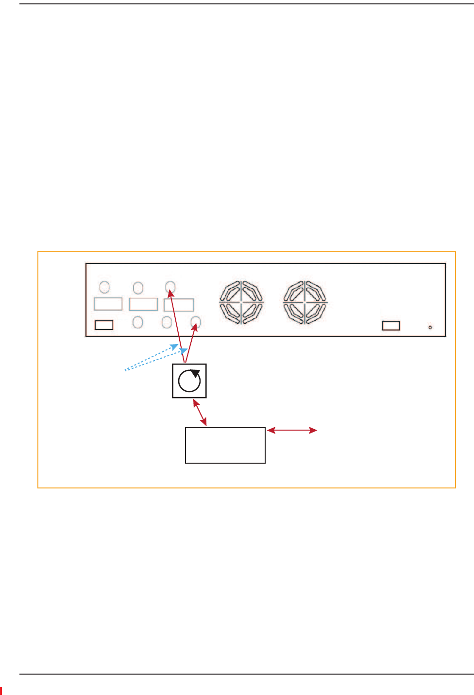
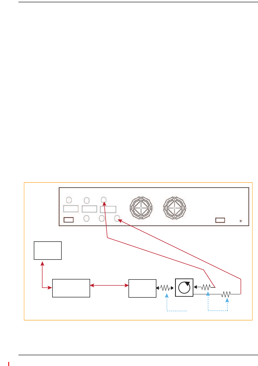
ConnectingaDuplexBaseStationtoaFusionWidebandMainHub
NOTE: Whenconnectingtoaduplexbasestation,useacirculatororduplexerbetweenitandtheFusion
WidebandMainHub.
NOTE: YoucaninsertattenuatorsbetweenthecirculatororduplexerandHubasneeded.
1ǦǦǤ
2ǦǤ
3ǦǦDOWNLINKͳǡ
ʹǡ͵Ǥ
4ǦǤ
5ǦǦUPLINKͳǡ
ʹǡ͵Ǥ
6Ǧ Ǥ
Figure41.Duplex Base Station to a Fusion Wideband Main Hub
Duplex
Base Station
Band 1 Band 2 Band 3
UL1 UL2 UL3
Alarms
DL1 DL2 DL3
AC Power
N-male to N-male
coaxial cable
T1/E1 to
Mobile
Switching
Center
Insert attenuator
(if needed)
NOTE: This applies to Band 1, Band 2, and Band 3.
Circulator
N-male to N-male
coaxial cable
Installing Fusion Wideband
Page 150 InterReach Fusion Wideband Installation, Operation, and Reference Manual
© 2013 TE Connectivity Ltd D-620616-0-20 Rev H • TECP-77-044 Issue 7 • May 2013
CAUTION! OnlyTEpersonnelorTEͲauthorizedinstallationpersonnelshouldconnecttheFusionWideband
MainHubtoabasestationorrepeater.Exceedingthemaximuminputpowercouldcausefailure
oftheFusionWidebandMainHub(referto“RemoteAccessUnitConnectors”onpage57for
maximumpowerspecifications).Ifthemaximumcompositepoweristoohigh,attenuationis
required.
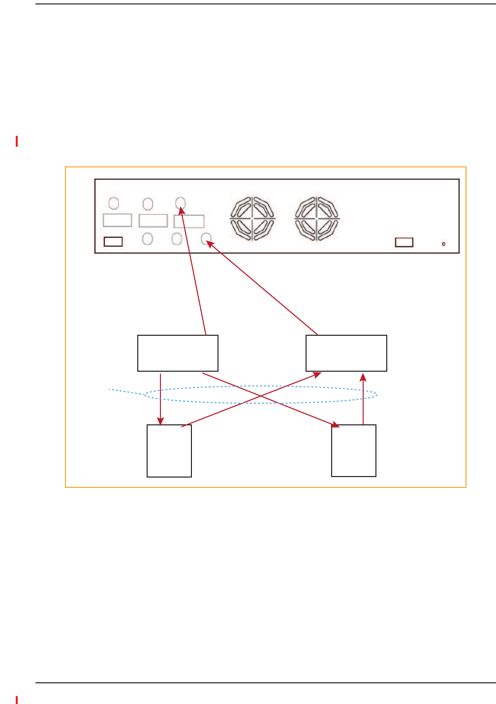
Ȁ
ǡͶʹͳͷͲǤ
Figure42.Connecting a Fusion Wideband Main Hub to Multiple Base Stations
3ConnectingaFusionWidebandMainHubRFBandtoMultipleBTSs
Band 1 Band 2 Band 3
UL1 UL2 UL3
Alarms
DL1 DL2 DL3
AC Power
Insert attenuators
(if needed)
2 x 1 Power
Combiner/Splitter
N-male to N-male
coaxial-jumper cables
between Combiner/Splitter and
Fusion Main Hub’s Uplink Port
for each on Band 1, Band 2, or Band 3
2 x 1 Power
Combiner/Splitter
N-male to N-male
coaxial-jumper cables
between Combiner/Splitter and
Fusion Main Hub’s Downlink Port
for either Band 1, Band 2, or Band 3
BTS 1
UL DL
BTS 2
UL DL
Interfacing the Fusion Wideband Main Hub to an RF Source
InterReach Fusion Wideband Installation, Operation, and Reference Manual Page 151
D-620616-0-20 Rev H • TECP-77-044 Issue 7 • May 2013 © 2013 TE Connectivity Ltd.
CAUTION! TErecommendsthatyouusealightningarrestororsurgeprotectorinaroofͲtopantenna
configuration.InsertthelightningarrestororsurgeprotectorbetweentheroofͲtopantennaand
therepeaterconnectedtotheFusionWidebandMainHubRFBand.
1ǦǦǦǤ
2ǦǦ
Ǥ
3ǦǦǤ
4ǦǦǤ
5ǦǦǤ
6ǦǦ1Ǥ
7ǦǦ2Ǥ
8ǦǦDOWNLINK
ͳǡʹǡ͵Ǥȋ
ǤȌ
9ǦǦ3Ǥ
10 ǦǦUPLINK
ͳǡʹǡ͵Ǥ
Figure43.Connecting a Fusion Wideband Main Hub to a Roof-top Antenna
3ConnectingaFusionWidebandMainHubtoaRoofͲTopAntenna
Band 1 Band 2 Band 3
UL1 UL2 UL3
Alarms
DL1 DL2 DL3
AC Power
Attenuator
(optional)
NOTE: This applies to Band 1, Band 2, and Band 3.
N-male to N-male
coaxial cable
Rooftop
Antenna
N-male to N-male
coaxial cable
Grounded
Surge Suppressor
Rooftop
Antenna
Circulator
1 2

Installing Fusion Wideband
Page 152 InterReach Fusion Wideband Installation, Operation, and Reference Manual
© 2013 TE Connectivity Ltd D-620616-0-20 Rev H • TECP-77-044 Issue 7 • May 2013
Ǥ
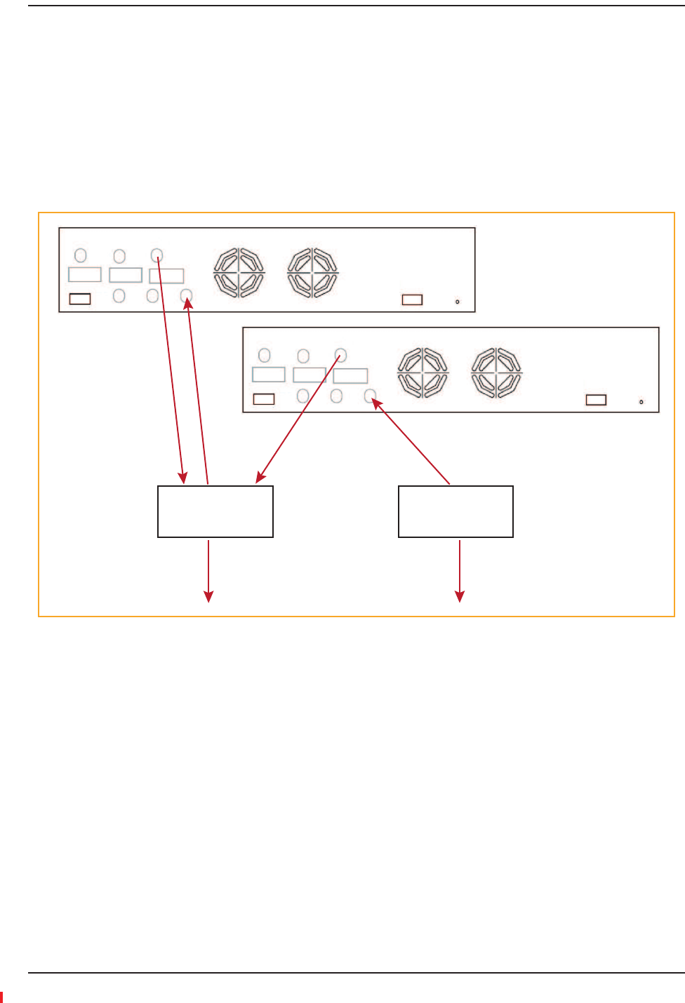
ConnectingMultipleFusionWidebandMainHubstoanRFSource
Ȁ
Ǥ
Ȁ
Ǥ
CAUTION! OnlyTEpersonnelorTEͲauthorizedinstallationpersonnelshouldconnecttheFusionWideband
MainHubtoabasestationorrepeater.Exceedingthemaximuminputpowercouldcausefailure
oftheFusionWidebandMainHub(referto“RemoteAccessUnitConnectors”onpage57for
maximumpowerspecifications).Ifthemaximumcompositepoweristoohigh,attenuationis
required.
1ǣ
2ȀǦǦ
ǣ
aȀUPLINK
bȀDOWNLINK
3Ȁǣ
aǯUPLINK ȋͳǡʹǡ͵Ȍ
Ȁ
bǯDOWNLINK ȋͳǡʹǡ͵Ȍ
Ȁ
cǯUPLINK ȋͳǡʹǡ͵Ȍ
Ȁ
dǯDOWNLINK ȋͳǡʹǡ͵Ȍ
Ȁ
NOTE: ConnectionsshouldnotcrossBands.Forexample,allBand1connectionsshouldbemadetothe
samehybridpowercombiner/splitterconnectedtotherepeaterBTSthatmatchestheBand1
frequency.
3ConnectingaFusionWidebandMainHubtoFlexwaveFocus
3ConnectingMultipleFusionWidebandMainHubstoaSimplexRepeaterorBTS
Quantity Item
2 hybrid power combiner/splitters—one for uplink and one for downlink (2x1 for two Fusion Wideband Main
Hubs, 3x1 for three, 4x1 for four, and so on)
1 N-male to N-male coaxial jumper cable between each power combiner/splitter and the base station
2 N-male to N-male coaxial jumper cables between each power combiner/splitter and each Fusion Wideband
Main Hub RF Band (either Band 1 or Band 2)
Interfacing the Fusion Wideband Main Hub to an RF Source
InterReach Fusion Wideband Installation, Operation, and Reference Manual Page 153
D-620616-0-20 Rev H • TECP-77-044 Issue 7 • May 2013 © 2013 TE Connectivity Ltd.
4Ȅǡ
Ǥ
5ǤThewarrantydoesnotcoverdamagecausedwhenan
ungroundedHubispoweredon.
NOTE: Usea50ohmterminatoronanyunusedpowercombiner/splitterports.
ͶͶǤ
ͺͳǤ
Figure44.Connecting Two Fusion Wideband Main Hub’s RF Band Ports to a Simplex Repeater or Base Station
Band 1 Band 2 Band 3
UL1 UL2 UL3
Alarms
DL1 DL2 DL3
AC Power
N-male to N-male
coaxial-jumper cables
between Combiner/Splitter
and Fusion Main Hub’s
Uplink Port for either Band 1,
Band 2, or Band 3
2 x 1 Power
Combiner/Splitter
2 x 1 Power
Combiner/Splitter
N-male to N-male
coaxial-jumper cables
between Combiner/Splitter and
Fusion Main Hub’s Downlink Port
for either Band 1, Band 2, or Band 3
Band 1 Band 2 Band 3
UL1 UL2 UL3
Alarms
DL1 DL2 DL3
AC Power
N-male to N-male
coaxial-jumper cable
to Repeater or
Base Station
N-male to N-male
coaxial-jumper cable
to Repeater or
Base Station

Installing Fusion Wideband
Page 154 InterReach Fusion Wideband Installation, Operation, and Reference Manual
© 2013 TE Connectivity Ltd D-620616-0-20 Rev H • TECP-77-044 Issue 7 • May 2013
CAUTION! OnlyTEpersonnelorTEͲauthorizedinstallationpersonnelshouldconnecttheFusionWideband
MainHubtoabasestationorrepeater.Exceedingthemaximuminputpowercouldcausefailure
oftheFusionWidebandMainHub(referto“RemoteAccessUnitConnectors”onpage57for
maximumpowerspecifications).Ifthemaximumcompositepoweristoohigh,attenuationis
required.
1ǣ
2ǦǦ
Ǥ
3ȀǦǦ
ȀǤ
4ȀǦǦ
ǣ
aǯUPLINK ȋͳǡʹǡ͵Ȍ
Ȁ
bǯDOWNLINK ȋͳǡʹǡ͵Ȍ
Ȁ
cǯUPLINK ȋͳǡʹǡ͵Ȍ
Ȁ
dǯDOWNLINK ȋͳǡʹǡ͵Ȍ
Ȁ
NOTE: ConnectionsshouldnotcrossBands.Forexample,allBand1connectionsshouldbemadetothe
samehybridpowercombiner/splitterconnectedtotherepeaterBTSthatmatchestheBand1
frequency.
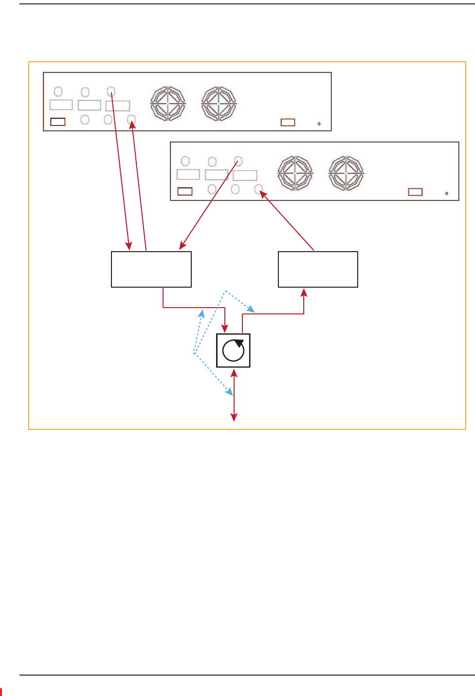
5ǤȄǡ
Ǥ
6ǤThewarrantydoesnotcoverdamagecausedwhen
anungroundedHubispoweredon.
NOTE: Usea50ohmterminatoronanyunusedpowercombiner/splitterports.
3ConnectingMultipleFusionWidebandMainHubstoaDuplexRepeaterorBTS
Quantity Item
2 hybrid power combiner/splitters—one for uplink and one for downlink (2x1 for two Fusion Wideband Main
Hubs, 3x1 for three, 4x1 for four, and so on)
1 N-male to N-male coaxial jumper cables to connect each Fusion Wideband Main Hub’s RF Band to the power
combiner/splitters
2 circulator
1 N-male to N-male coaxial jumper cable between each circulator and the repeater or base station
N-male to N-male coaxial jumper cable between each circulator and power combiner/splitter
Interfacing the Fusion Wideband Main Hub to an RF Source
InterReach Fusion Wideband Installation, Operation, and Reference Manual Page 155
D-620616-0-20 Rev H • TECP-77-044 Issue 7 • May 2013 © 2013 TE Connectivity Ltd.
ͶͷǤ
ǡǤ
Figure45.Connecting Two Fusion Wideband Main Hub’s RF Band Ports to a Duplex Repeater or Base Station
Band 1 Band 2 Band 3
UL1 UL2 UL3
Alarms
DL1 DL2 DL3
AC Power
N-male to N-male
coaxial-jumper cables
between Combiner/Splitter
and Fusion Main Hub’s
Uplink Port for either Band 1,
Band 2, or Band 3
2 x 1 Power
Combiner/Splitter
2 x 1 Power
Combiner/Splitter
N-male to N-male
coaxial-jumper cables
between Combiner/Splitter and
Fusion Main Hub’s Downlink Port
for either Band 1, Band 2, or Band 3
Band 1 Band 2 Band 3
UL1 UL2 UL3
Alarms
DL1 DL2 DL3
AC Power
Circulator
Base Station
to Repeater or
N-male to N-male
coaxial-jumper cable
N-male to N-male
coaxial-jumper cable
N-male to N-male
coaxial-jumper cable
Insert attenuator
(if needed)

Installing Fusion Wideband
Page 156 InterReach Fusion Wideband Installation, Operation, and Reference Manual
© 2013 TE Connectivity Ltd D-620616-0-20 Rev H • TECP-77-044 Issue 7 • May 2013
CONNECTINGCONTACTALARMSTOAFUSIONWIDEBANDSYSTEM
ȋȌ
Ǥ
•AlarmSourceȄǡȋȌ
ȋȌǤǦȋȌ
ǤǡDzdzͳͷǤ
NOTE: ThecontactcanbechangedtonormallyͲopen(NO)withAdminBrowser.Thisisnot
recommendedsincenoalarmwouldbesentifpowertotheFusionWidebandMainHubfails.
–Ǥ
–
ǦǦǤ
•AlarmSenseȄ͵Ǥ
ǦȋȌǦȋȌǤ
ǡ
ǤǤǡ
DzdzͳͲǤ
ͻͲǡǡ
ȋȌǡǤ
ȋȌǤ
Table90.AlarmTypes
Alarm
Type
Fusion Wideband
Connected to
Cable(s) Used Errors Detected
Source FlexWave 5-port Alarm Daisy-Chain Cable Faults
Source BTS 5-port Alarm Daisy-Chain Cable Faults and Warnings
In addition, a custom daisy-chain cable-to-BTS interface cable
is required. Make this interface cable to the desired length and
with the appropriate pin placement.
Sense Unison 5-port Alarm Daisy-Chain Cable
and the Alarm Sense Adapter Cable
Faults
Connecting Contact Alarms to a Fusion Wideband System
InterReach Fusion Wideband Installation, Operation, and Reference Manual Page 157
D-620616-0-20 Rev H • TECP-77-044 Issue 7 • May 2013 © 2013 TE Connectivity Ltd.
AlarmSource
ǡ
ǤDzdzͳͲ
Ǥ
NOTE: Thefollowingproceduresassumethatthesystemisinstalledandthathasbeenprogrammed
withbands.
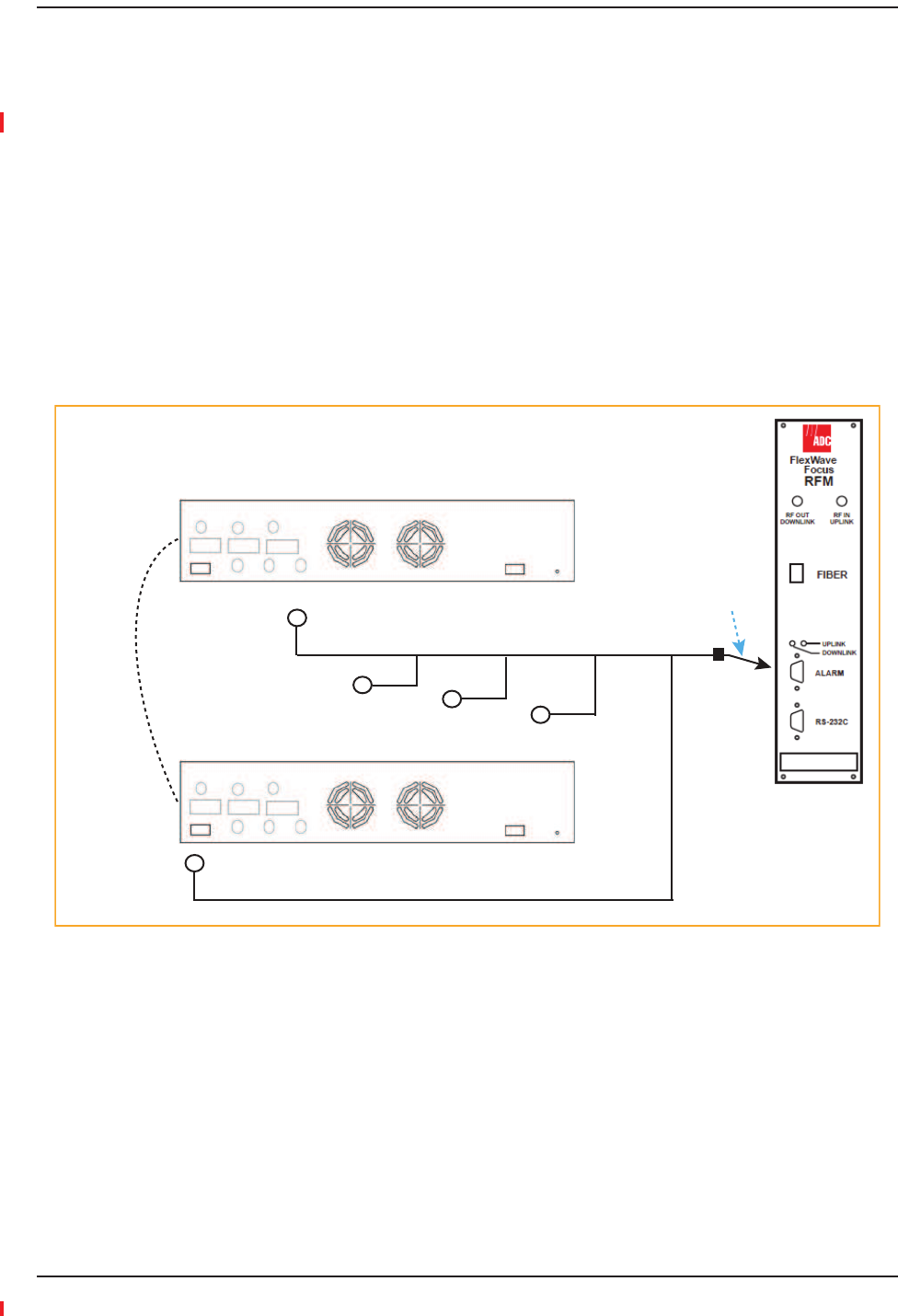
UsingFlexWaveFocustoMonitorFusionWideband
ǡ
ȋȌȋȌǡ
ͶǤȋȌǤ
Figure46.Connecting FlexWave to Fusion Wideband
Band 1 Band 2 Band 3
UL1 UL2 UL3
Alarms
DL1 DL2 DL3
AC Power
Band 1 Band 2 Band 3
UL1 UL2 UL3
Alarms
DL1 DL2 DL3
AC Power
Fusion Main Hub
May need
9-pin Adapter
that ships
with the cable
Alarm
Sense
5-port Alarm Daisy-Chain Cable
Alarm
Source
Alarm
Source
Installing Fusion Wideband
Page 158 InterReach Fusion Wideband Installation, Operation, and Reference Manual
© 2013 TE Connectivity Ltd D-620616-0-20 Rev H • TECP-77-044 Issue 7 • May 2013
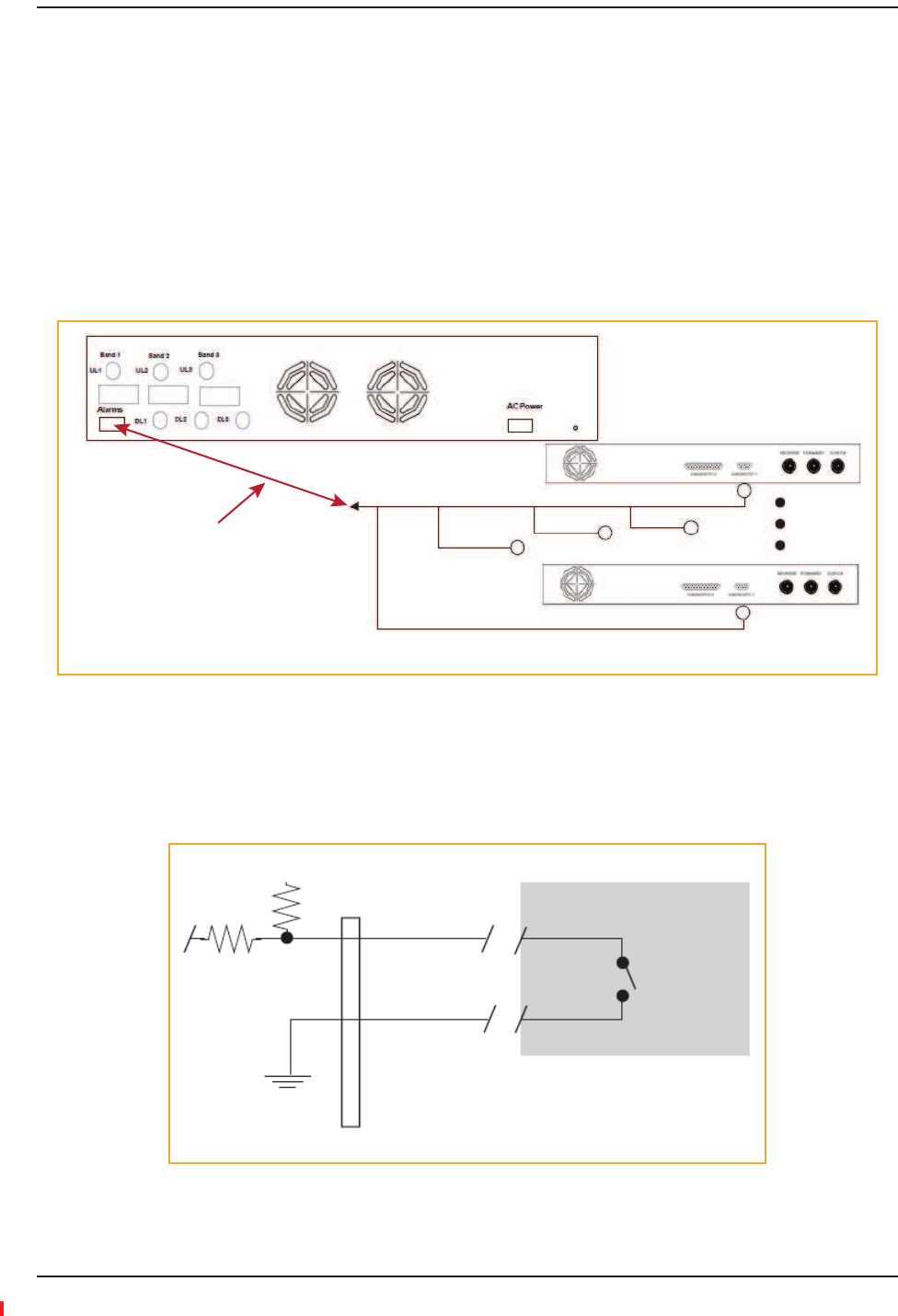
UsingaBaseStationtoMonitorFusionWideband
NOTE: TheBTSmustbeconfigured,bythecarrier,forcontactclosuremonitoringpriortoconnectinga
FusionWidebandMainHubtoit.
ǡ
ȋȌȋȌǡͶǤ
ǦǤ
ǦǦǡǦǤ
DzȀdz͵͵ȋȌǤ
Figure47.Using a BTS to Monitor Fusion Wideband
NOTE: Fornormallyopencontacts,thefaultandwarningcontactsneedtobewiredinparallelwith
otherMainHubs.
NOTE: TEdoesnotrecommendusingnormallyopencontacts.
Band 1 Band 2 Band 3
UL1 UL2 UL3
Alarms
DL1 DL2 DL3
AC Power
Band 1 Band 2 Band 3
UL1 UL2 UL3
Alarms
DL1 DL2 DL3
AC Power
Fusion Main Hub
Alarm
Sense
5-port Alarm Daisy-Chain Cable
Alarm
Source
BTS
Alarm
Source Interface
Cable
(custom-made, on-site)
Connecting Contact Alarms to a Fusion Wideband System
InterReach Fusion Wideband Installation, Operation, and Reference Manual Page 159
D-620616-0-20 Rev H • TECP-77-044 Issue 7 • May 2013 © 2013 TE Connectivity Ltd.
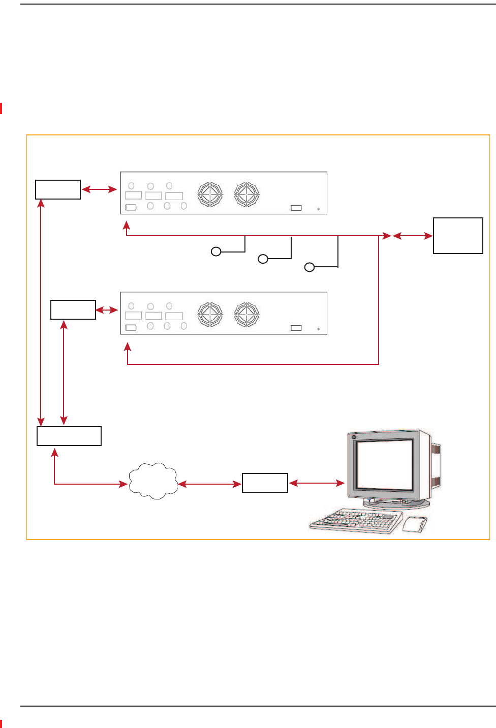
UsingaBaseStationandAdminBrowsertoMonitorFusionWideband
NOTE: TheBTSmustbeconfigured,bythecarrier,forcontactclosuremonitoringpriortoconnectinga
FusionWidebandMainHubtoit.
ǯƬ
ǡͶͺǤ
DzdzͳʹǤ
Figure48.Using a BTS and AdminBrowserto Monitor Fusion Wideband
Band 1 Band 2 Band 3
UL1 UL2 UL3
Alarms
DL1 DL2 DL3
AC Power
Fusion Main Hub
Alarm
Sense
5-port Alarm Daisy-Chain Cable
Alarm
Source
BTS
PSTN
Interface
Cable
(custom-made, on-site)
PC running
Standard
Browser
Software
Modem
Line Switch
Modem
Band 1 Band 2 Band 3
UL1 UL2 UL3
Alarms
DL1 DL2 DL3
AC Power
Modem
Alarm
Source
Installing Fusion Wideband
Page 160 InterReach Fusion Wideband Installation, Operation, and Reference Manual
© 2013 TE Connectivity Ltd D-620616-0-20 Rev H • TECP-77-044 Issue 7 • May 2013
AlarmSense
Dzdz
ȋ
AdminBrowserUserManualȌǤ
NOTE: Thisprocedureassumesthatthesystemisinstalledandthathasbeenprogrammedwithbands.
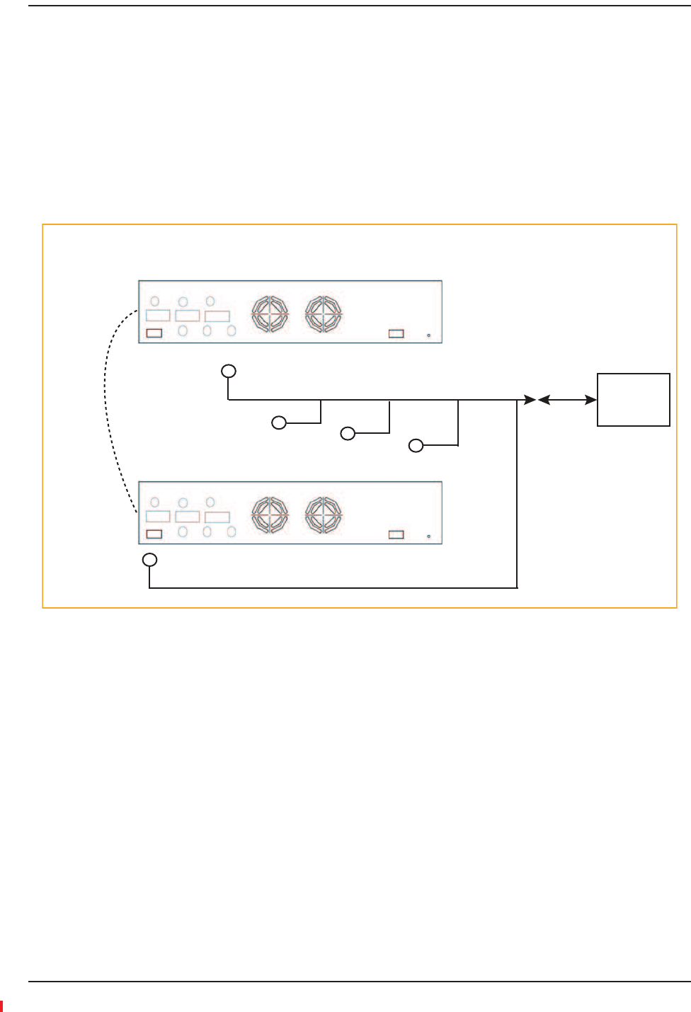
ǡ
ȋȌȋȌǡͶͻǤ
ȋȌǤ
Figure49.Using Fusion Wideband to Monitor Unison
Ǥ
ǦǤ
Ǥ
Figure50.Alarm Sense Contacts
5-port Alarm Daisy-Chain Cable
Up to 5 Unison Main Hubs
Alarm
Source
Alarm
Source
Alarm
Sense
Fusion Main Hub
Alarm Sense
Adapter Cable
+5V
8
1
External
Equipment
Contacts
Diagnostic 1
Connecting Contact Alarms to a Fusion Wideband System
InterReach Fusion Wideband Installation, Operation, and Reference Manual Page 161
D-620616-0-20 Rev H • TECP-77-044 Issue 7 • May 2013 © 2013 TE Connectivity Ltd.
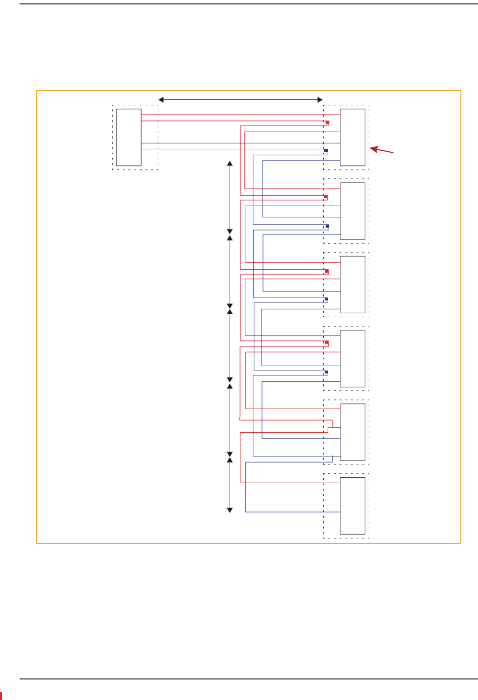
AlarmCables
ͷͳͷǦǦȋͶͲʹͶǦ͵Ȍǡ
Ǥ
Figure51.5-port Alarm Daisy-Chain Cable
1.2 meters (4 feet)
J1
Female
J2
Male
J3
Male
J4
Male
J5
Male
J6
Male
J7
Female
Terminator
NOTE: Do not daisy-chain
Fusion Main Hubs
with FlexWave Focus
if you want both faults
and warnings from Fusion.
Only faults are reported if
you combine Fusion with
FlexWave in the same daisy
chain.
7
9
4
5
DB-9 female to
Base Station,
FlexWave Focus,
or the Alarm Sense
Adapter Cable when
connecting Unison
7
9
4
5
Splice
Splice
DB-9 male to Fusion,
Unison, FlexWave Focus,
Alarm Port
Connector
Hood
DB-9 male to Fusion,
Unison, FlexWave Focus,
Alarm Port
DB-9 male to Fusion,
Unison, FlexWave Focus,
Alarm Port
DB-9 male to Fusion,
Unison, FlexWave Focus,
Alarm Port
7
9
4
5
Splice
Splice
7
9
4
5
Splice
Splice
7
9
4
5
Splice
Splice
7
9
4
5
7
4
Option 1: DB-9 to Fusion,
Unison, FlexWave Focus
Alarm Port. J7 not used.
Option 2: Use J2-J5
for Alarm ports. Use J6 to
connect to an additional
Alarm Daisy-Chain Cable.
Do not use J7.
Option 3: Connect
fewer than 5 ports and
connect J7 to the lowest
unused port to terminate
the daisy chain.
.5 meter
(1.5 feet)
.5 meter
(1.5 feet)
.5 meter
(1.5 feet)
.5 meter
(1.5 feet)
.25 meter
(.75 feet)
Installing Fusion Wideband
Page 162 InterReach Fusion Wideband Installation, Operation, and Reference Manual
© 2013 TE Connectivity Ltd D-620616-0-20 Rev H • TECP-77-044 Issue 7 • May 2013
ALARMMONITORINGCONNECTIVITYOPTIONS
NOTE: Thefollowingproceduresassumethatthesystemisinstalledandthathasbeenprogrammed
withbands.
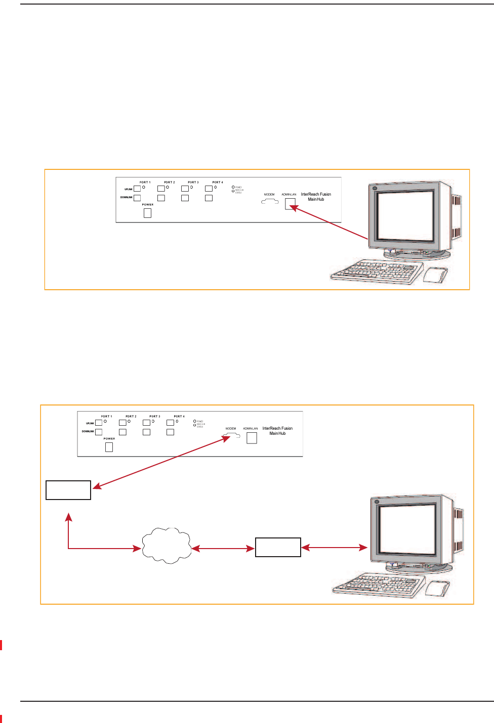
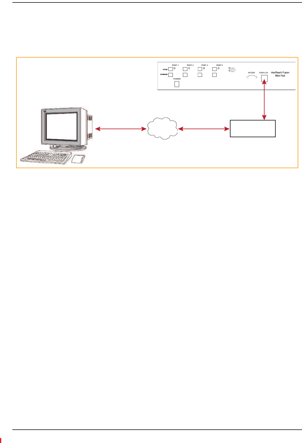
DirectConnection
ǡRJ-45 100 BASE-T
ǯǦǤ
Figure52.OA&M Direct Connection
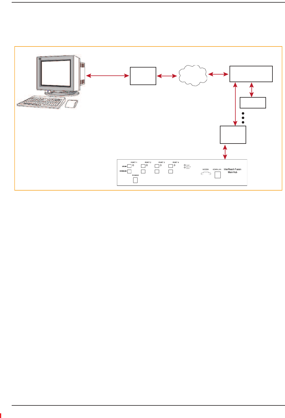
ModemConnection
ǡ
ǦǤ
Figure53.OA&M Modem Connection
NOTE: Referto“CoaxialCable”onpage198forthemodemcablewiringinformation.
PC running
Standard
Browser
Software
Cross-over
100 BASE-T Cable
AdminBrowser is
resident in Fusion.
PSTN
PC running
Standard
Browser
Software
Modem
#140272-0
Modem
#140272-0
#4028-10
Straight-Through
Modem cable
#4028-10
Straight-Through
Modem cable
Alarm Monitoring Connectivity Options
InterReach Fusion Wideband Installation, Operation, and Reference Manual Page 163
D-620616-0-20 Rev H • TECP-77-044 Issue 7 • May 2013 © 2013 TE Connectivity Ltd.
ǣ
•Ǧǣͳǡʹ
•ǦǣʹǤ
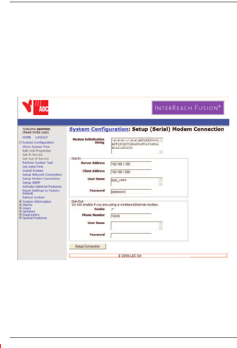
SettingUpFusionWidebandModem(USRModem)UsingAdminBrowser
Ǧǣ
1Ǥ
2SystemConfigurationǤ
3SelectSetupModemConnectionǤǣ
4ǣǤ
•
•
5SetupConnectionǤ
TE
Installing Fusion Wideband
Page 164 InterReach Fusion Wideband Installation, Operation, and Reference Manual
© 2013 TE Connectivity Ltd D-620616-0-20 Rev H • TECP-77-044 Issue 7 • May 2013
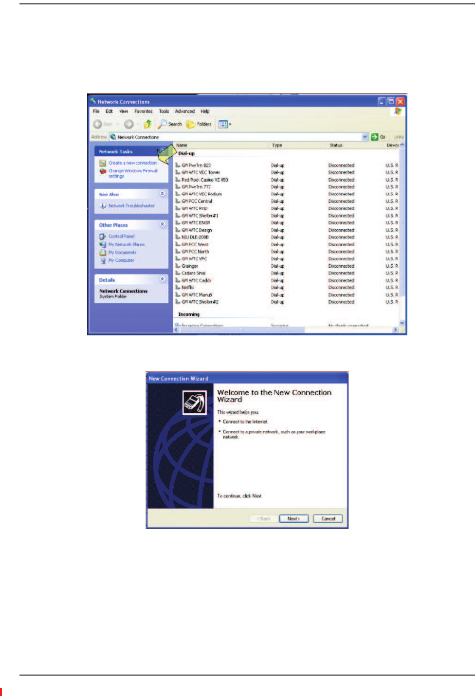
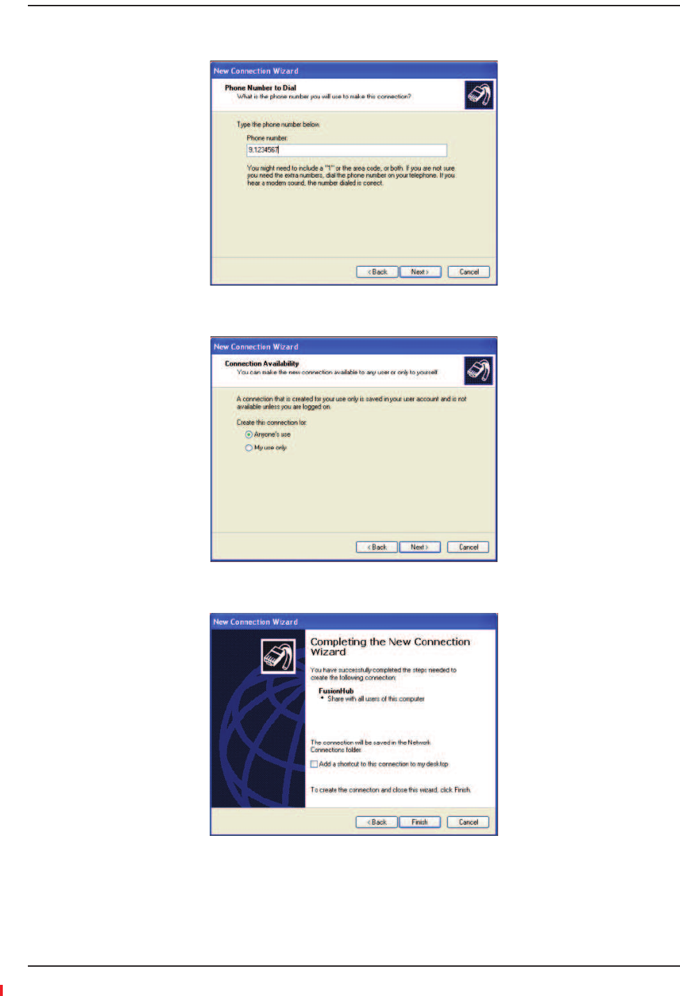
SettingUpaPCModemUsingWindows
ǦǤ
1StartǡSettingsǡNetworkConnectionsǤǤ
2ClickCreateanewconnectionǤǤ
Alarm Monitoring Connectivity Options
InterReach Fusion Wideband Installation, Operation, and Reference Manual Page 165
D-620616-0-20 Rev H • TECP-77-044 Issue 7 • May 2013 © 2013 TE Connectivity Ltd.
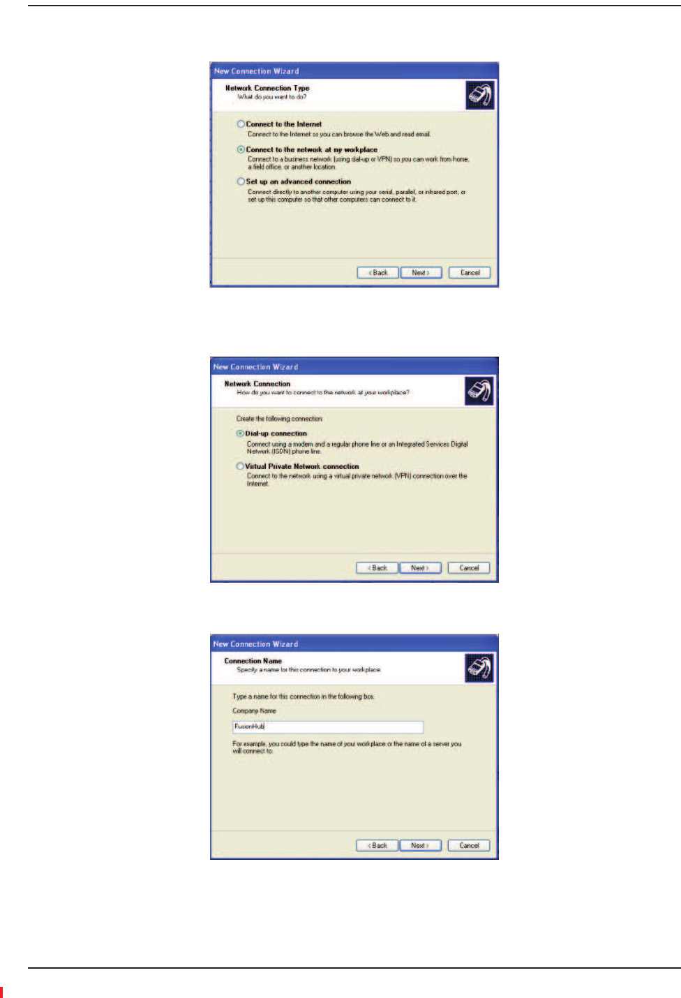
3NextǤǤ
4ConnecttothenetworkatmyworkplaceNextǢ
Ǥ
5DialǦupconnectionNextǢǤ
Installing Fusion Wideband
Page 166 InterReach Fusion Wideband Installation, Operation, and Reference Manual
© 2013 TE Connectivity Ltd D-620616-0-20 Rev H • TECP-77-044 Issue 7 • May 2013
6NextǢǤ
7PhonenumberNextǢǤ
8Anyone’suseNextǢǤ
Alarm Monitoring Connectivity Options
InterReach Fusion Wideband Installation, Operation, and Reference Manual Page 167
D-620616-0-20 Rev H • TECP-77-044 Issue 7 • May 2013 © 2013 TE Connectivity Ltd.
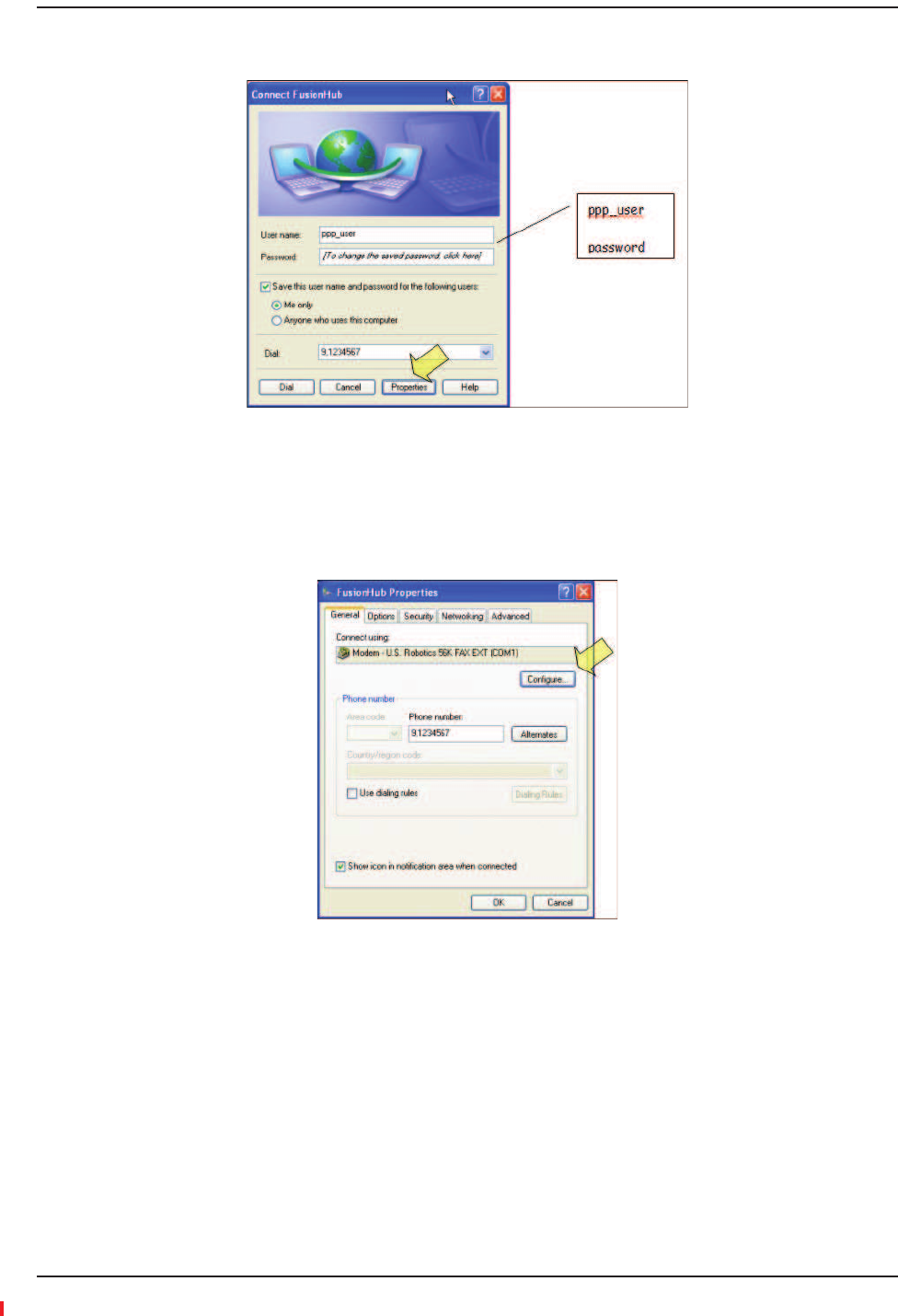
9FinishǢǤ
10 PropertiesǢǤ
ǣ
•ǣppp_user
•ȋǡȌǣpassword
Installing Fusion Wideband
Page 168 InterReach Fusion Wideband Installation, Operation, and Reference Manual
© 2013 TE Connectivity Ltd D-620616-0-20 Rev H • TECP-77-044 Issue 7 • May 2013
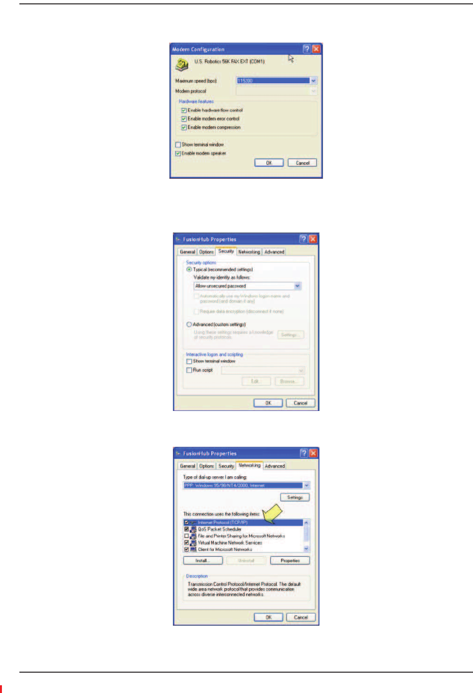
11 Configure...Ǥ
12 OKǤ
13 SecurityǢǤ
14 TypicalNetworkingǢǤ
Alarm Monitoring Connectivity Options
InterReach Fusion Wideband Installation, Operation, and Reference Manual Page 169
D-620616-0-20 Rev H • TECP-77-044 Issue 7 • May 2013 © 2013 TE Connectivity Ltd.
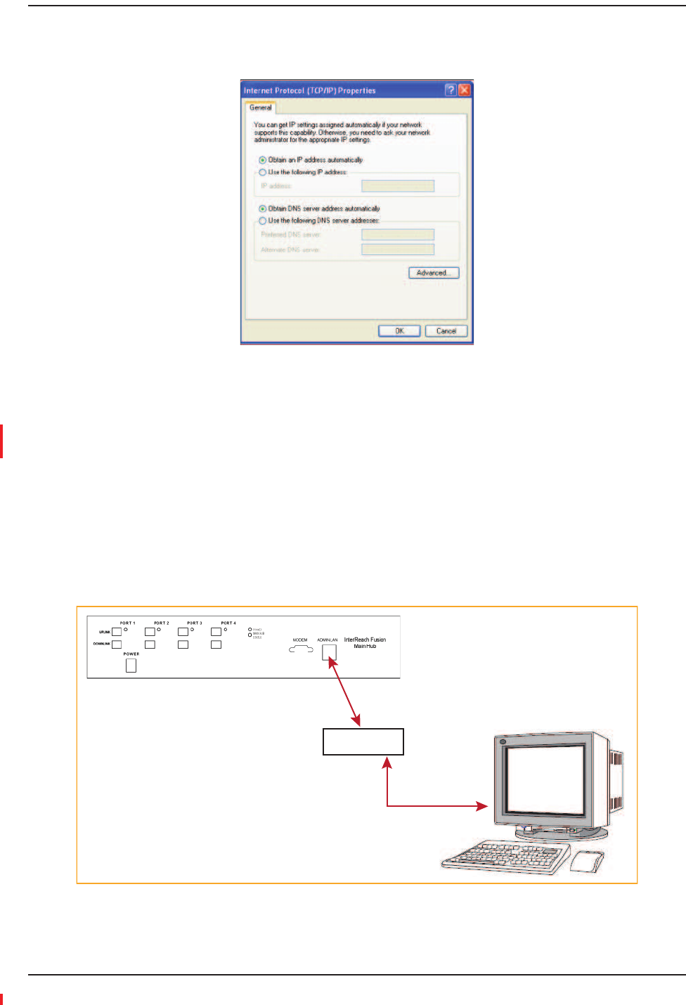
15 InternetProtocol(TCP/IP)PropertiesǢ
Ǥ
16 ObtainanIPaddressautomaticallyObtainDNSserveraddressautomaticallyǡ
OKǤ
17 Ǧǡ
ǡDz
ȋȌdzͳ͵Ǥ
100BASEͲTPortExpanderConnection
ͳͲͲǦǤͶǦǤ
Ǥ
Figure54.OA&M Connection using a 232 Port Expander
PC running
Standard
Browser
Software
LAN Switch
100 BASE-T
Ethernet connection
AdminBrowser is
resident in Fusion.
100 BASE-T Cable
RJ-45 Male to RJ-45 Male
Installing Fusion Wideband
Page 170 InterReach Fusion Wideband Installation, Operation, and Reference Manual
© 2013 TE Connectivity Ltd D-620616-0-20 Rev H • TECP-77-044 Issue 7 • May 2013
POTSLineSharingSwitchConnection
ǡǤ
Figure55.OA&M Connection Using a POTS Line Sharing Switch
Modem
#4028-10 Straight-Through
Modem cable
PC running
Standard
Browser
Software
PSTN
Modem
#140272-0
#4028-10
Straight-Through
Modem cable
Line Sharing Switch
4- or 8-port
4-port: #240031-0
8-port: #240052-0
Standard
phone
cable
Up to 4 modems
per switch
Modem
#140272-0
Alarm Monitoring Connectivity Options
InterReach Fusion Wideband Installation, Operation, and Reference Manual Page 171
D-620616-0-20 Rev H • TECP-77-044 Issue 7 • May 2013 © 2013 TE Connectivity Ltd.
Figure56.Cascading Line Sharing Switches
EthernetRFModem
ǦǤǡ
Ǥ
#4028-10
Straight-Through
Modem cable
PC running
Standard
Browser
Software
PSTN
Modem
#140272-0
#4028-10
Straight-Through
Modem cable
4- or 8-Port
Line Sharing Switch
4- or 8-port
Line Sharing Switch PNs:
4-port: #240031-0
8-port: #240052-0
Standard phone cable
4- or 8-Port
Line Sharing Switch
4- or 8-Port
Line Sharing Switch
4- or 8-Port
Line Sharing Switch
4- or 8-Port
Line Sharing Switch
M
o
d
e
m
M
o
d
e
m
M
o
d
e
m
M
o
d
e
m
M
o
d
e
m
M
o
d
e
m
M
o
d
e
m
M
o
d
e
m
M
o
d
e
m
M
o
d
e
m
M
o
d
e
m
M
o
d
e
m
M
o
d
e
m
M
o
d
e
m
M
o
d
e
m
M
o
d
e
m
Installing Fusion Wideband
Page 172 InterReach Fusion Wideband Installation, Operation, and Reference Manual
© 2013 TE Connectivity Ltd D-620616-0-20 Rev H • TECP-77-044 Issue 7 • May 2013
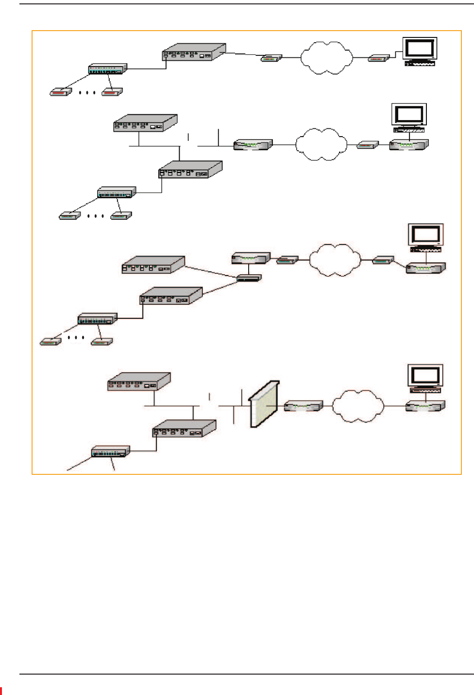
EthernetLANConnection
Ǥ
ͶǦǤ
Figure57.OA&M Connection Using Ethernet and ENET/232 Serial Hub
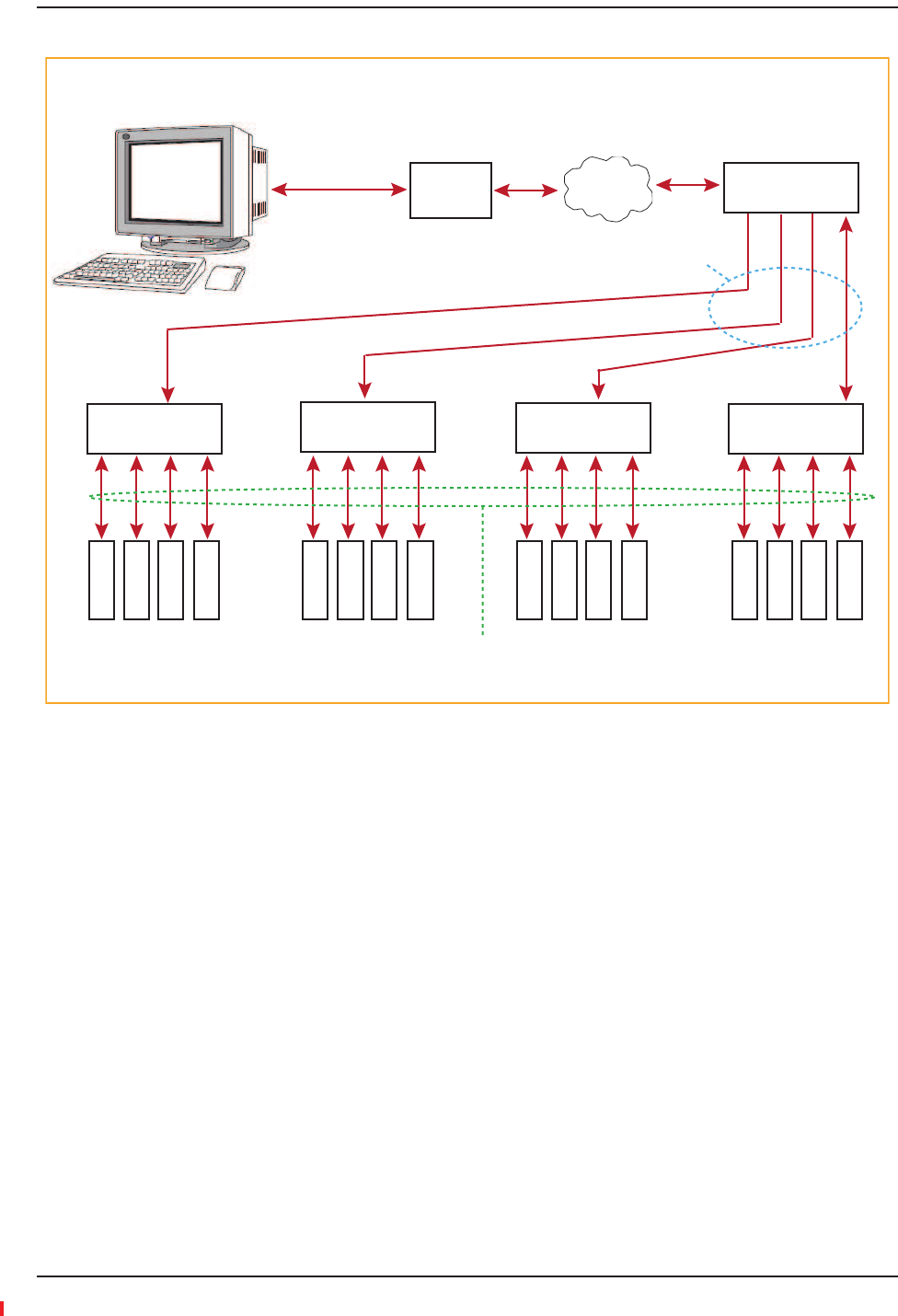
SNMPInterface
ȋȌ
ȋȌǤ
Ǥ
ȋȌͳʹǤ
PC running
Standard
Browser
Software
TCP/IP LAN Switch
Ethernet Ethernet
100 BASE-T Cable
Male RJ-45 to Male RJ-45
Alarm Monitoring Connectivity Options
InterReach Fusion Wideband Installation, Operation, and Reference Manual Page 173
D-620616-0-20 Rev H • TECP-77-044 Issue 7 • May 2013 © 2013 TE Connectivity Ltd.
Figure58.Fusion Wideband SNMP Configuration Options
Remote Unit Remote Unit
Expansion Hub
Expansion Hub
Main Hub
RS-232
Modem Port
PPP Modem PSTN
PPP Modem
Remote Unit Remote Unit
Expansion Hub
Main Hub
PSTN
(b) Connection to multiple systems through Dial-in router
Remote Unit Remote Unit
(c) DSL Modem through internet
(d) Connection to corporate LAN through firewall
LAN
Ethernet
Port Ethernet
Port
Dialup Router/
Firewall Modem
PPP PPP
Router
Main Hub Ethernet
Port
Ethernet
Port
Router
Switch
DSL Modem DSL Modem
Router
PSTN/
Internet
Ethernet
Port
Ethernet Port
Main Hub
LAN
Firewall
Router Router
Internet

Installing Fusion Wideband
Page 174 InterReach Fusion Wideband Installation, Operation, and Reference Manual
© 2013 TE Connectivity Ltd D-620616-0-20 Rev H • TECP-77-044 Issue 7 • May 2013

InterReach Fusion Wideband Installation, Operation, and Reference Manual Page 175
D-620616-0-20 Rev H • TECP-77-044 Issue 7 • May 2013 ©2013 TE Connectivity Ltd.
REPLACINGFUSIONWIDEBANDCOMPONENTS
ReplacinganRAU................................................................................................................................................................. 176
ReplacetheRAU .....................................................................................................................................................................176
PerformSystemTest ..............................................................................................................................................................176
ChecktheRAULEDs ...............................................................................................................................................................177
ReplacingaFusionWidebandExpansionHub ...................................................................................................................... 178
ReplaceaFusionWidebandExpansionHub...........................................................................................................................178
AdminBrowserTasks ..............................................................................................................................................................178
ChecktheExpansionHubLEDs...............................................................................................................................................178
ReplacingaFusionWidebandMainHub .............................................................................................................................. 179
ReplaceaFusionWidebandMainHub...................................................................................................................................179
ConfiguretheNewFusionWidebandMainHub....................................................................................................................179
ChecktheLEDsontheNewMainHub ...................................................................................................................................180
Topics Page

Replacing Fusion Wideband Components
Page 176 InterReach Fusion Wideband Installation, Operation, and Reference Manual
© 2013 TE Connectivity Ltd D-620616-0-20 Rev H • TECP-77-044 Issue 7 • May 2013
REPLACINGANRAU
CAUTION! ThenewRAUmustsupportthesamebandsastheoneyouarereplacing.IftheRAUisofthe
wrongbandcombination,itwillnotoperateproperlyinthesystem.
1ǡSYSTEM INFORMATIONǤ
2SHOW SYSTEM TREEǡǡGET SYSTEM INFORMATION.
Ǥ
Ǥ
3CANCELǤ
4Ǥ
5Ǥ
6Ǥ
7Ǥ
8SYSTEM CONFIGURATION.
9SHOW SYSTEM TREEǤ
10 EDIT UNIT PROPERTIESǤ
11 SAVE PROPERTIESǤ
ǡǤ
CAUTION! DuringSystemTest,theentiresystemistemporarilyoffͲlineandnoRFisbeingtransmitted.
3ReplacetheRAU
3PerformSystemTest

Replacing an RAU
InterReach Fusion Wideband Installation, Operation, and Reference Manual Page 177
D-620616-0-20 Rev H • TECP-77-044 Issue 7 • May 2013 © 2013 TE Connectivity Ltd.
1ǯLINKALARMȋȀȌǤ
ǡǤ
2ǡ
ǡǡ
Ǥ
aLINKALARMǡ
Ǥ
Ǣ
Ǥ
bǯǡ
Ǥ
cȋͻͲȌǡǤ
3ChecktheRAULEDs

Replacing Fusion Wideband Components
Page 178 InterReach Fusion Wideband Installation, Operation, and Reference Manual
© 2013 TE Connectivity Ltd D-620616-0-20 Rev H • TECP-77-044 Issue 7 • May 2013
REPLACINGAFUSIONWIDEBANDEXPANSIONHUB
1Ǥ
2ǡǡǤ
3Ǥ
4ǡǡȂ
Ǥ
5Ǥ
•Ǥ
•ǡ
Ǥ
CAUTION! DuringSystemTest,theentiresystemistemporarilyoffͲlineandnoRFisbeingtransmitted.For
afullyloadedsystem(oneMainHub,fourExpansionHubs,and32RAUs),itcantakeupto90
secondstocompletethetest.
•Ǥ
–ǡǤ
–ǡǤ
•UL STATUSDL STATUSǤ
•E-HUB STATUS POWERǤ
•Ǥ
Ǥ
NOTE: RefertoDzdzͳͺfortroubleshootingusingtheLEDs.
3ReplaceaFusionWidebandExpansionHub
3AdminBrowserTasks
3ChecktheExpansionHubLEDs

Replacing a Fusion Wideband Main Hub
InterReach Fusion Wideband Installation, Operation, and Reference Manual Page 179
D-620616-0-20 Rev H • TECP-77-044 Issue 7 • May 2013 © 2013 TE Connectivity Ltd.
REPLACINGAFUSIONWIDEBANDMAINHUB
ǯ
ǤǤ
ǡǤ
ǡ
ǦǤ
1ǡǡSYSTEM INFORMATIONǡSHOW SYSTEM TREEǡ
ǡGET SYSTEM INFORMATIONǤ
2Ǥ
3Ǥ
4Ǥ
5Ǥ
6ǯ
ͳͲͲǦǤȀȌ
7Ǥ
8Ǥ
9Ǥ
Ǥ
Ǥͳʹ
Ǥ
CAUTION! DuringSystemTest,theentiresystemistemporarilyoffͲlineandnoRFisbeingtransmitted.
1Ǥ
2SYSTEM CONFIGURATIONǤ
3SET DATE/TIMEǤ
4SET DATE/TIMEǤ
5Ǥ
6ǡSYSTEM CONFIGURATIONǤ
7INSTALL SYSTEMǤ
8INSTALL SYSTEM ȋǡ
ǡǡȌǤ
9Ǥ
10 SYSTEM CONFIGURATIONSETUP NETWORK CONNECTION OR MODEM CONNECTION
Ǥ
3ReplaceaFusionWidebandMainHub
3ConfiguretheNewFusionWidebandMainHub

Replacing Fusion Wideband Components
Page 180 InterReach Fusion Wideband Installation, Operation, and Reference Manual
© 2013 TE Connectivity Ltd D-620616-0-20 Rev H • TECP-77-044 Issue 7 • May 2013
•ͷǦǤ
–ǡǤ
–ǡǤ
•ǡ
ǡPORTǤ
•DzdzͳͺǤ
NOTE: IfthereisnocommunicationbetweentheMainHubandtheExpansionHubs,usethe
AdminBrowsertoisolatesystemproblems.
3ChecktheLEDsontheNewMainHub

InterReach Fusion Wideband Installation, Operation, and Reference Manual Page 181
D-620616-0-20 Rev H • TECP-77-044 Issue 7 • May 2013 ©2013 TE Connectivity Ltd.
MAINTENANCE,TROUBLESHOOTING,ANDTECHNICAL
ASSISTANCE
Service................................................................................................................................................................................. 182
Maintenance ....................................................................................................................................................................... 183
CleaningtheFiberPorts .........................................................................................................................................................183
Considerations................................................................................................................................................................183
UsingCompressedAir.....................................................................................................................................................183
UsingIsopropylAlcohol ..................................................................................................................................................183
Troubleshooting .................................................................................................................................................................. 184
TroubleshootingUsingAdminBrowser...................................................................................................................................185
SystemTroubleshooting.................................................................................................................................................185
TroubleshootingRecommendations ..............................................................................................................................185
Fault/Warning/StatusIndications ..................................................................................................................................186
TroubleshootingUsingLEDs ...................................................................................................................................................186
TroubleshootingMainHubLEDsDuringNormalOperation ..........................................................................................186
TroubleshootingExpansionHubLEDsDuringNormalOperation ..................................................................................188
TroubleshootingCATV ......................................................................................................................................................... 189
TechnicalAssistance ............................................................................................................................................................ 190
Topics Page

Maintenance, Troubleshooting, and Technical Assistance
Page 182 InterReach Fusion Wideband Installation, Operation, and Reference Manual
© 2013 TE Connectivity Ltd D-620616-0-20 Rev H • TECP-77-044 Issue 7 • May 2013
SERVICE
ǦǤ
Ǥ
Ǥ
Address 541 E. Trimble Road
San Jose, California
95131-1224 USA
Help Hot Line
U.S. and Canada 1-800-530-9960
All Others +1-952-917-0761
Help Web URL http://www.te.com/WirelessSupport

Maintenance
InterReach Fusion Wideband Installation, Operation, and Reference Manual Page 183
D-620616-0-20 Rev H • TECP-77-044 Issue 7 • May 2013 © 2013 TE Connectivity Ltd.
MAINTENANCE
Ǥ
Ǥ
CleaningtheFiberPorts
ǯ
Ǥ
Considerations
•ǣ
–ǡǡǤ
–Ǥ
•Ǧǣ
–ͻͺΨǤ
UsingCompressedAir
1ǯǤ
2
Ǥ
UsingIsopropylAlcohol
1ǯǤ
2ʹǤͷǦǡǦ
Ǥ
3Ǥ
4Ǥ
ǡǤ

Maintenance, Troubleshooting, and Technical Assistance
Page 184 InterReach Fusion Wideband Installation, Operation, and Reference Manual
© 2013 TE Connectivity Ltd D-620616-0-20 Rev H • TECP-77-044 Issue 7 • May 2013
TROUBLESHOOTING
NOTE: FusionhasnouserͲserviceableparts.FaultyorfailedunitsarefullyreplaceablethroughTE;see
“Service”onpage182.
ǣ
•Ȁ
•
•ǡǡ
•
•
•
•
NOTE: Faultycablingisthecauseofavastmajorityofproblems.AllCATV75Ohmcableshouldbetested
toTIAͲ570ͲBspecifications.TheRAUwillbedamagedifthecableconnectorisnotinstalled
properly.
ǡ
Ǥ
ǡ
Ǥǡ“Service”onpage182.
ǣ
•
•
•ͳǤͲͲǡǤ
Ǥ
•ǫȋǦȌǫ
•
•ǫ

Troubleshooting
InterReach Fusion Wideband Installation, Operation, and Reference Manual Page 185
D-620616-0-20 Rev H • TECP-77-044 Issue 7 • May 2013 © 2013 TE Connectivity Ltd.
TroubleshootingUsingAdminBrowser
Ǥǡǯǡ
ǡǤ
NOTE: AdminBrowserv1.00displaysevents(faults,warnings,orstatusmessages)dependingonyour
viewpreference.Tochangeyourviewpreference,referto“ViewPreference”onpage38.
SystemTroubleshooting
ǡSYSTEM INFORMATIONǡGET FAULTS, WARNINGS AND STATUSESǤ
ǡǤ
ǢǢ
ǡǤ
NOTE: Systemcommandscantakelongertoexecutecomparedtocomponentcommands.
NOTE: ThisRAUicon indicatesthereisfaultontheRAU.Thisicon indicatesadisconnected
device.Youcannotrequeststatusonadisconnecteddevice.
TroubleshootingRecommendations
ǡǡǣ
•Ǥ
–Ǥ
–Ǣ
Dzdzͳͺ͵Ǥ
–Ǥ
•ǡ CLEAR ALL DISCONNECTSǤ
•Ǥ
•Ǥ
Ǥ
•ǣ
–Ǥ
–ǡ
Ǥ
–Ǥǡ
SHOW SYSTEM TREEǤSET OUT OF SERVICE/SET IN SERVICEǤ

Maintenance, Troubleshooting, and Technical Assistance
Page 186 InterReach Fusion Wideband Installation, Operation, and Reference Manual
© 2013 TE Connectivity Ltd D-620616-0-20 Rev H • TECP-77-044 Issue 7 • May 2013
Fault/Warning/StatusIndications
ǡ
ǤǤ
Ǥǡ
Ǥǡ
DzdzDzdzǤ
ǢǤ
NOTE: IfyouhavearedSTATUSLEDwithoutafaultmessage,itprobablyindicatesthattheunitislocked
out.
ǡǡ
Ǥ
TroubleshootingUsingLEDs
ǡǡǢ
Ǥ
ǡǡǤ
Ǥ
Ǥ
TroubleshootingMainHubLEDsDuringNormalOperation
ǯǤǡ
Ǥ

Troubleshooting
InterReach Fusion Wideband Installation, Operation, and Reference Manual Page 187
D-620616-0-20 Rev H • TECP-77-044 Issue 7 • May 2013 © 2013 TE Connectivity Ltd.
Table91.TroubleshootingMainHubPortLEDsDuringNormalOperation
During
Normal
Operation
Main Hub
Port LEDs
State Action Impact
Expansion
Hub Not
Connected
PORT Red If the Expansion Hub was disconnected
accidentally, re-connect the cables. The
LEDs should change to Green/Red
(then Green/Green, after 20 seconds, if
the Main Hub band has been
programmed).
When the Expansion Hub is to be
removed from service permanently,
use AdminBrowser’s ‘Clear All
Disconnect Status’ command to clear
all disconnect states to no connect
states.
The Expansion Hub was previously
connected, but it is not currently
connected; the Expansion Hub uplink
cable disconnected.
AdminBrowser clears all disconnects
caused by installation as part of the
clean-up process. After installation,
power cycle the Main Hub or use
AdminBrowser’s “Clear All Disconnect
Status” command.
Changes the Main Hub’s port LEDs to
Off/Off.
Expansion
Hub
Connected
PORT Flashing Red
(60 ppm)
Use AdminBrowser to determine the
exact cause of the Main Hub’s faults.
Lost communication with Expansion Hub;
could be Expansion Hub problem or fiber
cable problem.
The Expansion Hub communication
problems delay MH responses to
AdminBrowser commands, resulting in
command time-outs. You can disconnect
the offending Expansion Hub initially to
obtain status from the rest of the system,
then connect the Expansion Hub and
resolve the communication problem.
PORT Red The Expansion Hub or connected RAU
reports a fault condition; use
AdminBrowser to determine the exact
cause of the Expansion Hub and RAU’s
faults.
Degraded performance or unit may be
off-line.
Depends on fault condition.
Table92.TroubleshootingMainHubStatusLEDsDuringNormalOperation
During
Normal
Operation
Main Hub
Status LEDs
State Action Impact
At Any Time main hub
status
Red Use AdminBrowser to determine the
exact cause of the fault.
Power cycle one time. If the fault
remains, replace the Main Hub.
Internal Main Hub fault.
Use AdminBrowser to check if the Main
Hub is commanded Out-of-Service
(every Expansion Hub port status LED
will be red as well).
A power cycle will not clear a
commanded Out-of-Service, you must
use AdminBrowser to clear this state.
The Main Hub and all downstream units
are off-line.
main hub
status
Flashing Red
(60ppm)
Reduce input signal power. Signal compression.
At Any Time Power Red Replace the Main Hub. One or more power supplies are out of
specification.

Maintenance, Troubleshooting, and Technical Assistance
Page 188 InterReach Fusion Wideband Installation, Operation, and Reference Manual
© 2013 TE Connectivity Ltd D-620616-0-20 Rev H • TECP-77-044 Issue 7 • May 2013
TroubleshootingExpansionHubLEDsDuringNormalOperation
•LINKE-HUB/RAU
Ȁǡǡǡ
Ǥ
•POWERǡ EHUB STATUSǡDL STATUSǡ UL STATUS Ǥ
Table93.TroubleshootingExpansionHubPortLEDsDuringNormalOperation
During
Normal
Operation
Expansion
Hub Port
LEDs
State Action Impact
RAU is not
connected
PORT Off If the RAU was disconnected
accidentally, re-connect the CATV
cable. The Expansion Hub’s port LEDs
should change to Green/Red (then
Green/Green, after 20 seconds, if the
Main Hub is connected, powered on,
and has band programmed).
Use AdminBrowser’s “Clear All
Disconnect Status” command if you
are permanently removing the RAU
from service. The Expansion Hub’s
port LEDs should change to Off/Off.
The RAU was previously connected, but it
is not currently connected; the RAU cable
is disconnected.
RAU is
connected
PORT Red Disconnect/reconnect the CATV cable
to force power-on reset to the RAU. If
the port LEDs remain Red check for
the exact cause of Expansion Hub
faults using AdminBrowser.
Lost communications with the RAU. The
RAU could have powered down due to
over current; cable could have been
damaged.
PORT Flashing
Red (60
ppm)
The RAU reports a fault condition;
check for the exact cause of
Expansion Hub and RAU faults using
AdminBrowser.
Depends on the fault condition.
PORT Flashing
Red (60
ppm)
The Expansion Hub reports no
connection, cable shorts, or a current
port trap condition.
Expansion Hub communications with the
RAU. The Expansion Hub is at fault. The
cable could have been damaged. The cable
leads may be shorted.
Table94.TroubleshootingExpansionHubStatusLEDsDuringNormalOperation
During
Normal
Operation
Expansion
Hub Status
LEDs
State Action Impact
At Any Time ul status Red Check uplink fiber for optical loss.
Power cycle Expansion Hub one time
to check uplink laser.
No communications between the Main Hub
and the Expansion Hub.
Uplink laser failure.
dl status Red Check the downlink fiber for optical
loss
No communications with the Main Hub.
E-h
status
Red If either the UL STATUS or the DL
STATUS are also red, see above.
Cycle power on the Expansion Hub. If
fault remains, replace the Expansion
Hub.
Internal Expansion Hub fault (including
either of the above UL STATUS or DL
STATUS states).
Troubleshooting CATV
InterReach Fusion Wideband Installation, Operation, and Reference Manual Page 189
D-620616-0-20 Rev H • TECP-77-044 Issue 7 • May 2013 © 2013 TE Connectivity Ltd.
TROUBLESHOOTINGCATV
ǡ
Ǥ
NOTE: RecommendedminimumandmaximumCATVcablelengthsvarydependinguponthetypeof
CATVcableused.Referto“CableandConnectorRequirements”onpage107.
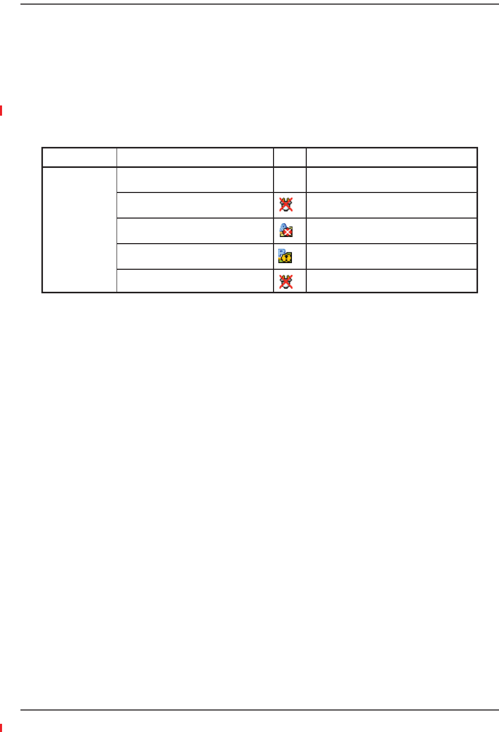
Table95.SummaryofCATVCableWiringProblems
Problem Type Message Icon Impact
Loose connector,
shorted conductor
or improper
connection to the
shield.
None High phase noise, degraded signal on both
Downlink and Uplink (high bit error rate)
No communication with RAUn RAU unable to communicate with Hub,
degraded performance or RAU off-line
Portn UL RF path loss is too high Increased ripple in the uplink path, decreased
UL gain, or no UL gain
The DL RF path loss is too high Increased ripple in the downlink path, RAU
off-line
RAUn over current or port short RAU will not power on.

Maintenance, Troubleshooting, and Technical Assistance
Page 190 InterReach Fusion Wideband Installation, Operation, and Reference Manual
© 2013 TE Connectivity Ltd D-620616-0-20 Rev H • TECP-77-044 Issue 7 • May 2013
TECHNICALASSISTANCE
ǢDzdzͳͺʹǤ
ǡǡǦǡ
ǤǤ
•
•
•ǡǡ
•ȋȌǡ
•
•
•ǡǡ

InterReach Fusion Wideband Installation, Operation, and Reference Manual Page 191
D-620616-0-20 Rev H • TECP-77-044 Issue 7 • May 2013 ©2013 TE Connectivity Ltd.
APPENDIXA:CABLESANDCONNECTORS
75OhmCATVCable ............................................................................................................................................................. 192
GeneralSpecifications ............................................................................................................................................................192
RecommendedCATVCableLengths.......................................................................................................................................192
ConnectorsandToolsforCableEnds .....................................................................................................................................196
FiberOpticalCables ............................................................................................................................................................. 197
CoaxialCable ....................................................................................................................................................................... 198
StandardModemCable ....................................................................................................................................................... 199
TCP/IPCrossͲOverCable ...................................................................................................................................................... 200
DBͲ9toDBͲ9NullModemCable .......................................................................................................................................... 201
Topics Page

Appendix A: Cables and Connectors
Page 192 InterReach Fusion Wideband Installation, Operation, and Reference Manual
© 2013 TE Connectivity Ltd D-620616-0-20 Rev H • TECP-77-044 Issue 7 • May 2013
75OHMCATVCABLE
GeneralSpecifications
•ȋȌ
•ȋȌȋȌ
•ǤǯͷͶ
Ǥ
•
•ͷǦ
•
–Ǧͷͻǣ
ȈǣͲȋͲǤȌ
ȈǣͳͷͲȋͶͻʹǤȌ
–Ǧǣ
ȈǣͲȋͲǤȌ
ȈǣͳͲȋͷͷͺǤȌ
–Ǧͳͳǣ
ȈǣͲȋͲǤȌ
ȈǣʹͷȋͻͲʹǤȌ
RecommendedCATVCableLengths
ǤȋǤȌ
•ǣ
•ʹͲͷͷǦͷͻǤǦͳǤ
•ʹʹͻǦǤǦʹǤ
•ʹʹͻ͵ǦͳͳǤǦ͵Ǥ
•ʹͲͷǦͷͻ
•ʹʹͻǦ
•ʹʹͻ͵Ǧͳͳ
75 Ohm CATV Cable
InterReach Fusion Wideband Installation, Operation, and Reference Manual Page 193
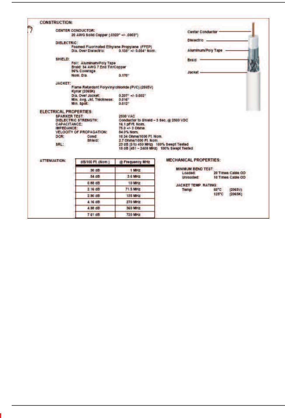
D-620616-0-20 Rev H • TECP-77-044 Issue 7 • May 2013 © 2013 TE Connectivity Ltd.
Figure59.CommScope 2065V for RG-59
Appendix A: Cables and Connectors
Page 194 InterReach Fusion Wideband Installation, Operation, and Reference Manual
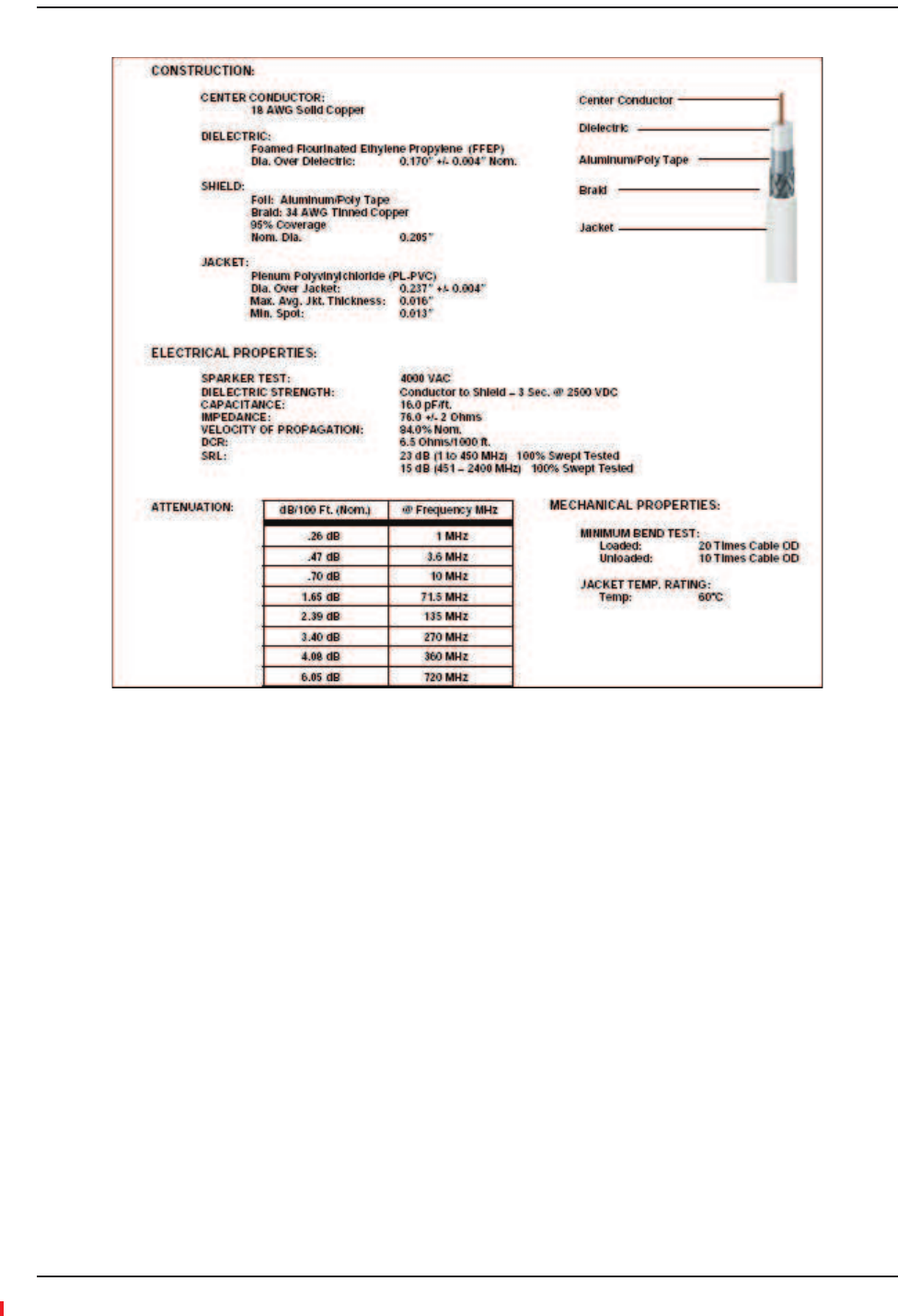
© 2013 TE Connectivity Ltd D-620616-0-20 Rev H • TECP-77-044 Issue 7 • May 2013
Figure60.CommScope 2079V for RG-6
75 Ohm CATV Cable
InterReach Fusion Wideband Installation, Operation, and Reference Manual Page 195
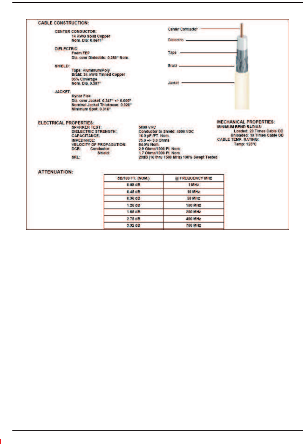
D-620616-0-20 Rev H • TECP-77-044 Issue 7 • May 2013 © 2013 TE Connectivity Ltd.
Figure61.CommScope 2293K for RG-11
NOTE: TErequiressolidcoppercenterconductorCATVcableforproperDCvoltagetotheRAUand
maximumdistances.

Appendix A: Cables and Connectors
Page 196 InterReach Fusion Wideband Installation, Operation, and Reference Manual
© 2013 TE Connectivity Ltd D-620616-0-20 Rev H • TECP-77-044 Issue 7 • May 2013
ConnectorsandToolsforCableEnds
ǣ
•ǣʹͲͷ
•ǣǦͶ
•ǦͳǡǦͶǡͳͲͲ
•ǣʹʹͻ
•ǣǦͷͷ
•ǦͳǡǦ͵ͷǡͳͲͲ
•ǣʹʹͻ͵
•ǣǦͳ
•ǦͳǡǦǡͳͲͲ
ǡǦǦ
Ǥ
ͻǡǦǡǡ
ǦǦǤ
Table96.SystemGain(Loss)RelativetoCATVCableLength
Cable
Type
CommScope
Part Number
Plenum
Rated
Solid Copper
Conductor
Copper Clad
Conductor
Zero-loss RF
Maximum
Length
(meters)
Distance
Where RF
is 10dB
Below Input
RF
(meters)
RG-59 2065V Yes X 130 180
2022V Yes X 100 100*
5572R No X 95 95*
5565 No X 130 180
RG-6 2279V Yes X 140 190
2275V Yes X 140 150*
5726 No X 140 140*
5765 No X 140 190
RG-11 2293K Yes X 235 320
2285K Yes X 235 300*
5913 No X 235 300*
* Exceeding the distance of copper-clad cable will result in the attached RAU becoming non-functional.
If the distance of a cable run is at its maximum and is of concern, TE recommends the use of solid
copper cable to ensure successful operation.

Fiber Optical Cables
InterReach Fusion Wideband Installation, Operation, and Reference Manual Page 197
D-620616-0-20 Rev H • TECP-77-044 Issue 7 • May 2013 © 2013 TE Connectivity Ltd.
FIBEROPTICALCABLES
•ȋȌ
•ȋȌȋȌ
•
•ǦʹǤͷρȀͳʹͷρǦʹͺǡǤ
•ȀȋǦȌ
ȋǦǦȌǡ
•ǣ
–ǦǣͷͲͲȋͳǡͶͲȌȂ͵
–ǦǣȋͳͻǡͺͷȌȂ͵

Appendix A: Cables and Connectors
Page 198 InterReach Fusion Wideband Installation, Operation, and Reference Manual
© 2013 TE Connectivity Ltd D-620616-0-20 Rev H • TECP-77-044 Issue 7 • May 2013
COAXIALCABLE
•ȋǦȌ
•ȋǦȌ

Standard Modem Cable
InterReach Fusion Wideband Installation, Operation, and Reference Manual Page 199
D-620616-0-20 Rev H • TECP-77-044 Issue 7 • May 2013 © 2013 TE Connectivity Ltd.
STANDARDMODEMCABLE
ȋͶͲʹͺǦͳͲȌǯǤ
Figure62.Standard Modem Cable Pinouts
DB-9 Connector
Pin
DB-25 Connector
Pin
1
2
3
4
5
6
7
8
9
8
3
2
20
7
6
4
5
22
Appendix A: Cables and Connectors
Page 200 InterReach Fusion Wideband Installation, Operation, and Reference Manual
© 2013 TE Connectivity Ltd D-620616-0-20 Rev H • TECP-77-044 Issue 7 • May 2013
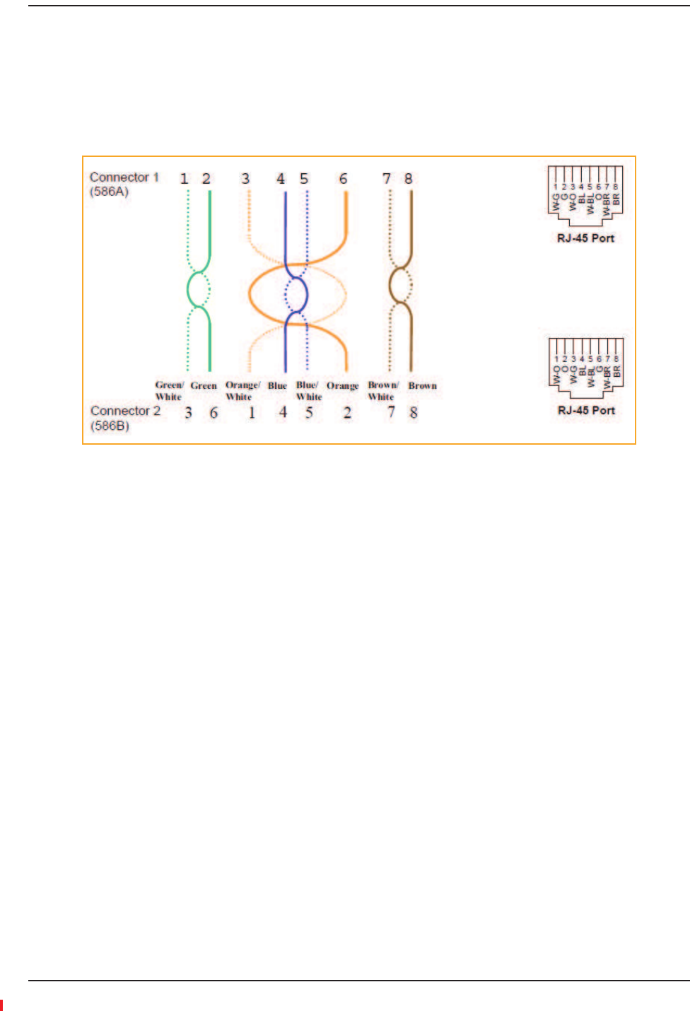
TCP/IPCROSSͲOVERCABLE
ȀǦȋͶͲͻǦȌ
ǤǤ
͵Ǥ
Figure63.Wiring Map for TCP/IP Cable
DB-9 to DB-9 Null Modem Cable
InterReach Fusion Wideband Installation, Operation, and Reference Manual Page 201
D-620616-0-20 Rev H • TECP-77-044 Issue 7 • May 2013 © 2013 TE Connectivity Ltd.
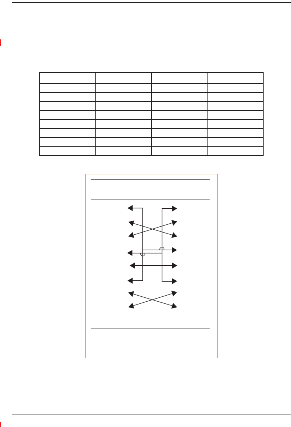
DBͲ9TODBͲ9NULLMODEMCABLE
ǦͻǦͻǯȀ
Ǧʹ͵ʹǤͻ
ͶǤ
Figure64.DB-9 Female to DB-9 Female Null Modem Cable Diagram
Table97.DBͲ9FemaletoDBͲ9FemaleNullModemCablePinout
From Signal To Signal
P1-4 DTR P2-6, P2-1 DSR, DCD
P1-6 DSR P1-1, P2-4 DCD, DTR
P1-3 TXD P2-2 RXD
P1-2 RXD P2-3 TXD
P1-5 GND P2-5 GND
P1-7 RTS P2-8 CTS
P1-8 CTS P2-7 RTS
P1-9 N/C N/C N/C
DB-9 Connector
Pin
DB-9 Connector
Pin
1
2
3
4
5
6
7
8
9
1
2
3
4
5
6
7
8
9
Note that for each DB-9 connector, pins 1 and 6 are tied
together and sent to pin 4 of the opposite connector,
providing the required handshake signals.

Appendix A: Cables and Connectors
Page 202 InterReach Fusion Wideband Installation, Operation, and Reference Manual
© 2013 TE Connectivity Ltd D-620616-0-20 Rev H • TECP-77-044 Issue 7 • May 2013

InterReach Fusion Wideband Installation, Operation, and Reference Manual Page 203
D-620616-0-20 Rev H • TECP-77-044 Issue 7 • May 2013 ©2013 TE Connectivity Ltd.
APPENDIXB:COMPLIANCE
FusionWidebandSystemApprovalStatus ........................................................................................................................... 204
700MHzLTEProducts............................................................................................................................................................204
800SMR/iDENProducts .........................................................................................................................................................204
850CellularProducts..............................................................................................................................................................204
1800DCSProducts .................................................................................................................................................................204
1900PCSProducts..................................................................................................................................................................204
2100UMTSProducts ..............................................................................................................................................................205
1700/2100AWSProducts ......................................................................................................................................................205
2500WiMAXProducts............................................................................................................................................................205
2600MHzLTEProducts..........................................................................................................................................................205
InterReachFusionWidebandMainHubandExpansionHub.................................................................................................206
HumanExposuretoRF......................................................................................................................................................... 207
Topics Page

Appendix B: Compliance
Page 204 InterReach Fusion Wideband Installation, Operation, and Reference Manual
© 2013 TE Connectivity Ltd D-620616-0-20 Rev H • TECP-77-044 Issue 7 • May 2013
FUSIONWIDEBANDSYSTEMAPPROVALSTATUS
Ǥ
700MHzLTEProducts
•ǣǡǡͲͻͷͲǡ͵ǡͲͻͷͲǦͳǡͳǡ
Ǥ
•ǣͳͷ
•ǣʹ
800SMR/iDENProducts
•ǣǡǡͲͻͷͲǡ͵ǡͲͻͷͲǦͳǡͳǡ
Ǥ
•ǣͳͷ
•ǣͻͲ
850CellularProducts
•ǣǡǡͲͻͷͲǡ͵ǡͲͻͷͲǦͳǡͳǡ
Ǥ
•ǣͳͷ
•ǣʹʹ
1800DCSProducts
•ǣǡǡͲͻͷͲǡ͵ǡͲͻͷͲǦͳǡͳǡ
Ǥ
•ǣ͵ͲͳͶͺͻǦͺͳǤʹǤͳ
•ǣ͵ͲͲͲͻǦͶͻǤʹǤͳ
1900PCSProducts
•ǣǡǡͲͻͷͲǡ͵ǡͲͻͷͲǦͳǡͳǡ
Ǥ
•ǣͳͷ
•ǣʹͶ

Fusion Wideband System Approval Status
InterReach Fusion Wideband Installation, Operation, and Reference Manual Page 205
D-620616-0-20 Rev H • TECP-77-044 Issue 7 • May 2013 © 2013 TE Connectivity Ltd.
2100UMTSProducts
•ǣǡǡͲͻͷͲǡ͵ǡͲͻͷͲǦͳǡͳǡ
Ǥ
•ǣ͵ͲͳͶͺͻǦʹ͵ͳǤʹǤͳ
•ǣ͵ͲͳͻͲͺǦͳͳʹǤ͵Ǥͳ
1700/2100AWSProducts
•ǣǡǡͲͻͷͲǡ͵ǡͲͻͷͲǦͳǡͳǡ
Ǥ
•ǣͳͷ
•ǣʹ
2500WiMAXProducts
•ǣǡǡͲͻͷͲǡ͵ǡͲͻͷͲǦͳǡͳǡ
Ǥ
•ǣͳͷ
•ǣʹ
2600MHzLTEProducts
•ǣǡǡͲͻͷͲǡ͵ǡͲͻͷͲǦͳǡͳǡ
Ǥ
•ǣ͵ͲͳͶͺͻǦʹ͵ͳǤʹǤͳ
•ǣ͵ͲͳͻͲͺǦͳͳʹǤ͵Ǥͳ

Appendix B: Compliance
Page 206 InterReach Fusion Wideband Installation, Operation, and Reference Manual
© 2013 TE Connectivity Ltd D-620616-0-20 Rev H • TECP-77-044 Issue 7 • May 2013
InterReachFusionWidebandMainHubandExpansionHub
•ǣǡǡͲͻͷͲǦͳǡǡ
Ǥ
•ǣʹʹ
•ǣʹͶ
NOTE: ForCanadiancustomers,theManufacturer’sratedoutputpower1ofthisequipmentisforsingle
carrieroperation.Forsituationswhenmultiplecarriersignalsarepresent,theratingwouldhave
tobereducedby3.5dB,especiallywheretheoutputsignalisreͲradiatedandcancause
interferencetoadjacentbandusers.Thispowerreductionistobebymeansofinputpoweror
gainreductionandnotbyanattenuatorattheoutputofthedevice.
NOTE: ThisdevicecomplieswithPart15oftheFCCRules.Operationissubjecttothefollowingtwo
conditions:(1)thisdevicemaynotcauseharmfulinterference,and(2)thisdevicemustaccept
anyinterferencereceived,includinginterferencethatmaycauseundesiredoperation.
NOTE: ThisequipmenthasbeentestedandfoundtocomplywiththelimitsforaClassAdigitaldevice,
pursuanttoPart15oftheFCCRules.Theselimitsaredesignedtoprovidereasonableprotection
againstharmfulinterferencewhentheequipmentisoperatedinacommercialenvironment.
Thisequipmentgenerates,uses,andcanradiateradiofrequencyenergyand,ifnotinstalledand
usedinaccordancewiththeinstructionmanual,maycauseharmfulinterferencetoradio
communications.
ȀǤ
ǯ
Ǥ
1 “Manufacturer’s rated output power” refers to Fusion Wideband’s downlink P1dB. The power per carrier tables take
into account this power reduction for multiple carriers.
WARNING.NOTCONSUMERǤFCC
LICENSEESQUALIFIEDINSTALLERSǤMUSTFCCLicense
Ǥ
ǡ̈́ͳͲͲǡͲͲͲǤ
Part 90 Signal Boosters
WARNING.NOTCONSUMERǤFCC
LICENSEESQUALIFIEDINSTALLERSǤMUSTFCCLicense
Ǥ
ȋͶͻͲǤʹͳͻȌwww.fcc.gov/signalǦboosters/registrationǤ
ǡ
̈́ͳͲͲǡͲͲͲǤ

Human Exposure to RF
InterReach Fusion Wideband Installation, Operation, and Reference Manual Page 207
D-620616-0-20 Rev H • TECP-77-044 Issue 7 • May 2013 © 2013 TE Connectivity Ltd.
HUMANEXPOSURETORF
ǤǤȋȌ
Ǥ
ȋȌ͵ͲͲ
ͳͲͲǤǡǡǤ
Ǣ
ʹͲȋȀͺdzȌǤ
ʹͲǡǤ
ͳǤͷȋʹǤͶͻȌ
ǤͳǤͷǡǤ
ʹͲʹǡ
ʹǤͳͲͻͳǤ
ǡ
ǡǡͷ
DzEvaluationCompliancewithFCCGuidelinesforHumanExposuretoRadioFrequencyforElectric
FieldsdzǤ
Ǥ
ʹͲǣ
•͵ͲͲͳǤͷȀͳͷͲͲ
•ͳǤͷͳȀʹ
ǣ
S = PG / 4SR2
SȀʹ
PGǡȋ
ȌǡǡǤ
RǤ
ǣ
ͳͲǡǡ
ͶȋͳͳʹǤȌǤ
ͳͻͲͲǡǡ
Ǥ͵ǦͶǡͳǤͷǤ
ǡʹ͵ǤͷȋʹʹͶȌǤ
αȀͶSʹ
αʹʹͶȀȋͶ͵ǤͳͶȌȋͳʹʹȌʹαͲǤͲͲͳȀʹ
ǡʹͲǣ
αʹʹͶȀȋͶ͵ǤͳͶȌȋʹͲȌʹαͲǤͲͶȀʹ

Appendix B: Compliance
Page 208 InterReach Fusion Wideband Installation, Operation, and Reference Manual
© 2013 TE Connectivity Ltd D-620616-0-20 Rev H • TECP-77-044 Issue 7 • May 2013

InterReach Fusion Wideband Installation, Operation, and Reference Manual Page 209
D-620616-0-20 Rev H • TECP-77-044 Issue 7 • May 2013 ©2013 TE Connectivity Ltd.
APPENDIXC:FAULTS,WARNINGS,STATUSTABLESFOR
FUSION,FUSIONWIDEBAND,FUSIONSINGLESTAR
FaultsReportedbyMainHubs ............................................................................................................................................. 210
FaultsReportedforSystemCPU........................................................................................................................................... 213
FaultsforExpansionHubs.................................................................................................................................................... 214
FaultsforRAUs .................................................................................................................................................................... 216
MessagesforMainHubs...................................................................................................................................................... 217
WarningMessages .................................................................................................................................................................217
StatusMessages .....................................................................................................................................................................217
MessagesforSystemCPUs................................................................................................................................................... 222
MessagesforExpansionHubs .............................................................................................................................................. 223
MessagesforRAUs .............................................................................................................................................................. 226
ǡ
Ǥ
Topics Page

Appendix C: Faults, Warnings, Status Tables for Fusion, Fusion Wideband, Fusion SingleStar
Page 210 InterReach Fusion Wideband Installation, Operation, and Reference Manual
© 2013 TE Connectivity Ltd D-620616-0-20 Rev H • TECP-77-044 Issue 7 • May 2013
FAULTSREPORTEDBYMAINHUBS
ǦǤ
ǡ
Ǥ
Ǥ
Ǥǡ
Ǥǡ
DzdzDzdzǤ
ǢǤ
NOTE: IfyouhavearedSTATUSLEDwithoutafaultmessage,itprobablyindicatesthattheunitislocked
out.
Table98.FaultMessagesforMainHubs
Message
Number
Description Reason/Action
{MF01} Software error occurred and recovered. If this happens repeatedly, replace the Hub.
{MF02} Software error occurred and recovered. If this happens repeatedly, replace the Hub.
{MF03} Software error occurred and recovered. If this happens repeatedly, replace the Hub.
{MF04} Software reset occurred and recovered, or firmware
download.
If this happens repeatedly, replace the Hub.
{MF05} Software error occurred and recovered. If this happens repeatedly, replace the Hub.
{MF06} Problem detected in the Hub. Internal communication
reset.
Contact TE Support for more information.
{MF07} Hub power cycle. Hub power cycle.
{MF08} Internal communications failure. No internal communications in preceding 15 minutes.
{MF09} Hardware Reset. Commanded hardware power on reset
{MF10} Band not programmed. Use AdminBrowser to program the band.
{MF11} Hardware failure (DL Pilot PLL). Cycle power once. If fault persists, replace the Hub
{MF12} Hardware failure (DL Pilot Too High). Cycle power once. If fault persists, replace the Hub.
{MF13} Hardware failure (DL Pilot Too Low). Cycle power once. If fault persists, replace the Hub.
{MF14} Hardware failure (54 VDC). 54 VDC power supply is out of range, replace the Hub
{MF15} Hardware failure (RF VDC Power). Loss of DC power to RF circuits, replace the Hub.
{MF16} Self Lockout (All Bands). Hub has shutdown the system due to an internal fault.
System is offline.
{MF17} Hardware failure (DL PLL Band 1). Cycle power once. If fault persists, replace the Hub.
{MF18} Hardware failure (UL PLL Band 1). Cycle power once. If fault persists, replace the Hub
{ML19} Commanded Out-of-service (Band 1). Band 1 commanded out-of-service by User.
{MF20} Hardware failure (UL1 LO2 Band 1). Cycle power once. If the fault persists, replace the Hub.
{MF21} Problem detected in the Hub. Contact TE Support for more information.
{MF22} Problem detected in the Hub. Contact TE Support for more information.
{MF23} Problem detected in the Hub Contact TE Support for more information.
{MF24} Problem detected in the Hub. Contact TE Support for more information.
{MF25} Hardware failure (DL PLL Band 2). Cycle power once. If fault persists, replace the Hub.

Faults Reported by Main Hubs
InterReach Fusion Wideband Installation, Operation, and Reference Manual Page 211
D-620616-0-20 Rev H • TECP-77-044 Issue 7 • May 2013 © 2013 TE Connectivity Ltd.
{MF26} Hardware failure (UL PLL Band 2). Cycle power once. If fault persists, replace the Hub.
{ML27} Commanded Out-of-service (Band 2). Band 2 commanded out-of-service by User.
{MF28} Problem detected in the Hub. Contact TE Support for more information.
{MF29} Problem detected in the Hub. Contact TE Support for more information.
{MF30} Problem detected in the Hub. Contact TE Support for more information.
{MF31} Problem detected in the Hub. Contact TE Support for more information.
{MF32} Problem detected in the Hub. Contact TE Support for more information.
{MF33} Hardware failure (DL PLL Band 3). Cycle power once. If fault persists, replace the Hub.
{MF34} Hardware failure (UL PLL Band 3). Cycle power once. If fault persists, replace the Hub.
{ML35} Commanded Out-of-service (Band 3). Band 3 commanded out-of-service by User.
{MF36} Hardware failure (638 MHz PLL). Cycle power once. If fault persists, replace the Hub.
{MF37} Hardware failure (638 MHz PLL). Cycle power once. If fault persists, replace the Hub.
{MF38} Problem detected in the Hub. Contact TE Support for more information.
{MF39} Problem detected in the Hub. Contact TE Support for more information.
{MF40} Problem detected in the Hub. Contact TE Support for more information.
{MF41} Hardware failure (Optical Power Out). Cycle power once. If the fault persists, replace the Hub.
{MF42} Unable to sync with TDD frame (Band 1). Check input signal and/or user TDD settings.
{MF43} Unable to sync with TDD frame (Band 2). Check input signal and/or user TDD settings.
{MF44} Problem detected in the Hub. Contact TE Support for more information
{MF45} Problem detected in the Hub. Contact TE Support for more information.
{MF46} Problem detected in the Hub. Contact TE Support for more information.
{MF47} Problem detected in the Hub Contact TE Support for more information.
{MF48} Problem detected in the Hub. Contact TE Support for more information.
{MD129} Port 1 Disconnected. Unit is disconnected.
{MD130} Port 2 Disconnected. Unit is disconnected.
{MD131} Port 3 Disconnected. Unit is disconnected.
{MD132} Port 4 Disconnected. Unit is disconnected.
{MD133} Port 5 Disconnected. Unit is disconnected.
{MD134} Port 6 Disconnected. Unit is disconnected.
{MD135} Port 7 Disconnected. Unit is disconnected.
{MD136} Port 8 Disconnected. Unit is disconnected.
{MC137} Port 1 No Communications. No communications with remote unit.
{MC138} Port 2 No Communications. No communications with remote unit.
{MC139} Port 3 No Communications. No communications with remote unit.
{MC140} Port 4 No Communications. No communications with remote unit.
{MC141} Port 5 No Communications. No communications with remote unit.
{MC142} Port 6 No Communications. No communications with remote unit.
{MC143} Port 7 No Communications. No communications with remote unit.
{MC144} Port 8 No Communications. No communications with remote unit.
{MT145} Port 1 Cable Fault. Possible electrical short in the coax cable, or RAU problem.
Table98.FaultMessagesforMainHubs(Cont.)
Message
Number
Description Reason/Action

Appendix C: Faults, Warnings, Status Tables for Fusion, Fusion Wideband, Fusion SingleStar
Page 212 InterReach Fusion Wideband Installation, Operation, and Reference Manual
© 2013 TE Connectivity Ltd D-620616-0-20 Rev H • TECP-77-044 Issue 7 • May 2013
{MT146} Port 2 Cable Fault. Possible electrical short in the coax cable, or RAU problem.
{MT147} Port 3 Cable Fault. Possible electrical short in the coax cable, or RAU problem.
{MT148} Port 4 Cable Fault. Possible electrical short in the coax cable, or RAU problem.
{MT149} Port 5 Cable Fault. Possible electrical short in the coax cable, or RAU problem.
{MT150} Port 6 Cable Fault. Possible electrical short in the coax cable, or RAU problem.
{MT151} Port 7 Cable Fault. Possible electrical short in the coax cable, or RAU problem.
{MT152} Port 8 Cable Fault. Possible electrical short in the coax cable, or RAU problem.
{MT153} Port 1 Trip. Remote Unit is drawing too much current.
{MT154} Port 2 Trip. Remote Unit is drawing too much current.
{MT155} Port 3 Trip. Remote Unit is drawing too much current.
{MT156} Port 4 Trip. Remote Unit is drawing too much current.
{MT157} Port 5 Trip. Remote Unit is drawing too much current.
{MT158} Port 6 Trip. Remote Unit is drawing too much current.
{MT159} Port 7 Trip. Remote Unit is drawing too much current.
{MT160} Port 8 Trip. Remote Unit is drawing too much current.
{MF161} Problem detected in the Hub. Contact TE Support for more information.
{MF162} Problem detected in the Hub. Contact TE Support for more information.
{MF163} Problem detected in the Hub. Contact TE Support for more information.
{MF164} Problem detected in the Hub. Contact TE Support for more information.
{MF165} Problem detected in the Hub. Contact TE Support for more information.
{MF166} Problem detected in the Hub. Contact TE Support for more information.
{MF167} Problem detected in the Hub. Contact TE Support for more information.
{MF168} Problem detected in the Hub. Contact TE Support for more information.
{MF169} Problem detected in the Hub. Contact TE Support for more information.
{MF170} Problem detected in the Hub. Contact TE Support for more information.
{MF171} Problem detected in the Hub. Contact TE Support for more information.
{MF172} Problem detected in the Hub. Contact TE Support for more information.
{MF173} Problem detected in the Hub. Contact TE Support for more information.
{MF174} Problem detected in the Hub. Contact TE Support for more information.
{MF175} Problem detected in the Hub. Contact TE Support for more information.
{MF176} Problem detected in the Hub. Contact TE Support for more information.
Table98.FaultMessagesforMainHubs(Cont.)
Message
Number
Description Reason/Action

Faults Reported for System CPU
InterReach Fusion Wideband Installation, Operation, and Reference Manual Page 213
D-620616-0-20 Rev H • TECP-77-044 Issue 7 • May 2013 © 2013 TE Connectivity Ltd.
FAULTSREPORTEDFORSYSTEMCPU
Table99.FaultsforSystemCPU
Message
Number
Description Reason/Action
{SF01} No internal communications. No internal communications in preceding 2 minutes. Power cycle to
clear.
{SF02} Unable to open file (sysinfo). System CPU rebooted.
{SF03} Unable to open file (sysstat). System CPU rebooted.
{SF04} Invalid internal response. System CPU rebooted, internal command does not return valid response
after 4 retries.
{SF05} No MAC address. System CPU rebooted, unable to read MAC address from the Ethernet
driver.
{SF06} Unable to open file (sysinfo_org). System CPU rebooted.
{SF07} Unable to open file (sbc_status). System CPU rebooted.
{SF08} Invalid internal field response. System CPU rebooted, internal command format invalid.
{SF09} Unable to open file (fileTTL). System CPU rebooted.
{SF10} Invalid internal ASCII response. System CPU rebooted, illegal number of bytes.
{SF11} Unable to open file (sysalarm). System CPU rebooted.
{SF12} Unable to open file (password_etb). System CPU rebooted.
{SF13} Unable to open file (CRC). System CPU rebooted.
{SF14} Problem detected in the System CPU. Contact TE Support for more information.
{SF15} pThread not executing. System CPU rebooted.
{SF16} Problem detected in the System CPU. Contact TE Support for more information.
{SF17} Problem detected in the System CPU. Contact TE Support for more information.
{SF18} Problem detected in the System CPU. Contact TE Support for more information.
{SF19} Problem detected in the System CPU. Contact TE Support for more information.
{SF20} Problem detected in the System CPU. Contact TE Support for more information.
{SF21} Problem detected in the System CPU. Contact TE Support for more information.
{SF22} Problem detected in the System CPU. Contact TE Support for more information.
{SF23} Problem detected in the System CPU. Contact TE Support for more information.
{SF24} Problem detected in the System CPU. Contact TE Support for more information.
{SF25} Problem detected in the System CPU. Contact TE Support for more information.
{SF26} Problem detected in the System CPU. Contact TE Support for more information.
{SF27} Problem detected in the System CPU. Contact TE Support for more information.
{SF28} Problem detected in the System CPU. Contact TE Support for more information.
{SF29} Problem detected in the System CPU. Contact TE Support for more information.
{SF30} Problem detected in the System CPU. Contact TE Support for more information.
{SF31} Problem detected in the System CPU. Contact TE Support for more information.
{SF32} Problem detected in the System CPU. Contact TE Support for more information.

Appendix C: Faults, Warnings, Status Tables for Fusion, Fusion Wideband, Fusion SingleStar
Page 214 InterReach Fusion Wideband Installation, Operation, and Reference Manual
© 2013 TE Connectivity Ltd D-620616-0-20 Rev H • TECP-77-044 Issue 7 • May 2013
FAULTSFOREXPANSIONHUBS
Table100.FaultMessagesforExpansionHubs
Message
Number
Description Reason/Action
{EF01} Software error occurred and recovered. If this happens repeatedly, replace the Hub.
{EF02} Software reset occurred and recovered, or
firmware download.
If this happens repeatedly, replace the Hub.
{EF03} Software reset occurred and recovered. If this happens repeatedly, replace the Hub.
{EF04} Software reset occurred and recovered. If this happens repeatedly, replace the Hub.
{EF05} Software error occurred and recovered. If this happens repeatedly, replace the Hub.
{EF06} Firmware download. Firmware download.
{EF07} Hub power cycle. Hub power cycle.
{EF08} MH communications failure. No communications from MH in THE preceding 90 seconds.
{EF09} MH communications failure. EH uplink messages not getting to the MH.
{EF10} Hardware failure (PLL). Cycle power once. If the fault persists, replace the Hub.
{EF11} Hardware failure (54 VDC). 54 VDC power supply is out of range, replace the Hub.
{EF12} Problem detected in the EH. Contact TE Support for more information.
{EF13} Band not programmed. Cycle power once. If the fault persists, replace the Hub.
{EF14} Low optical input power. Check downlink fiber connections.
{EF15} Hardware failure (Optical Output Power). Cycle power once. If the fault persists, replace the Hub.
{EF16} Self Lockout (All Bands). The Hub has shutdown the system due to an internal fault. The
system is offline.
{EF17} Commanded Out-of-service (Band 1). Band 1 commanded out-of-service by the user.
{EF18} Fault lockout (Band 1). Band 1 out-of-service due to an MH fault.
{EF19} Problem detected in the EH. Contact TE Support for more information.
{EF20} Problem detected in the EH. Contact TE Support for more information.
{EF21} Problem detected in the EH. Contact TE Support for more information.
{EF22} Problem detected in the EH. Contact TE Support for more information.
{EF23} Problem detected in the EH. Contact TE Support for more information.
{EF24} Problem detected in the EH. Contact TE Support for more information.
{EF25} Commanded Out-of-service (Band 2). Band 2 commanded out-of-service by the user.
{EF26} Fault lockout (Band 2). Band 2 out-of-service due to MH fault.
{EF27} Problem detected in the EH. Contact TE Support for more information.
{EF28} Problem detected in the EH. Contact TE Support for more information.
{EF29} Problem detected in the EH. Contact TE Support for more information.
{EF30} Problem detected in the EH. Contact TE Support for more information.
{EF31} Problem detected in the EH. Contact TE Support for more information.
{EF32} Problem detected in the EH. Contact TE Support for more information.
{EF33} Commanded Out-of-service (Band 3). Band 3 commanded out-of-service by the user.
{EF34} Fault lockout (Band 3). Band 3 out-of-service due to an MH fault.
{EF35} Problem detected in the EH. Contact TE Support for more information.
{EF36} Problem detected in the EH. Contact TE Support for more information.

Faults for Expansion Hubs
InterReach Fusion Wideband Installation, Operation, and Reference Manual Page 215
D-620616-0-20 Rev H • TECP-77-044 Issue 7 • May 2013 © 2013 TE Connectivity Ltd.
{EF37} Problem detected in the EH. Contact TE Support for more information.
{EF38} Problem detected in the EH. Contact TE Support for more information.
{EF39} Problem detected in the EH. Contact TE Support for more information.
{EF40} Problem detected in the EH. Contact TE Support for more information.
{ED129} Port 1 Disconnected. Unit is disconnected.
{ED130} Port 2 Disconnected. Unit is disconnected.
{ED131} Port 3 Disconnected. Unit is disconnected.
{ED132} Port 4 Disconnected. Unit is disconnected.
{ED133} Port 5 Disconnected. Unit is disconnected.
{ED134} Port 6 Disconnected. Unit is disconnected.
{ED135} Port 7 Disconnected. Unit is disconnected.
{ED136} Port 8 Disconnected. Unit is disconnected.
{EC137} Port 1 No Communications. No communications with remote unit.
{EC138} Port 2 No Communications. No communications with remote unit.
{EC139} Port 3 No Communications. No communications with remote unit.
{EC140} Port 4 No Communications. No communications with remote unit.
{EC141} Port 5 No Communications. No communications with remote unit.
{EC142} Port 6 No Communications. No communications with remote unit.
{EC143} Port 7 No Communications. No communications with remote unit.
{EC144} Port 8 No Communications. No communications with remote unit.
{ET145} Port 1 Cable Fault. Possible electrical short in the coaxial cable, or an RAU problem.
{ET146} Port 2 Cable Fault. Possible electrical short in the coaxial cable, or an RAU problem.
{ET147} Port 3 Cable Fault. Possible electrical short in the coaxial cable, or an RAU problem.
{ET148} Port 4 Cable Fault. Possible electrical short in the coaxial cable, or an RAU problem.
{ET149} Port 5 Cable Fault. Possible electrical short in the coaxial cable, or an RAU problem.
{ET150} Port 6 Cable Fault. Possible electrical short in the coaxial cable, or an RAU problem.
{ET151} Port 7 Cable Fault. Possible electrical short in the coaxial cable, or an RAU problem.
{ET152} Port 8 Cable Fault. Possible electrical short in the coaxial cable, or an RAU problem.
{ET153} Port 1 Trip. The Remote Unit is drawing too much current.
{ET154} Port 2 Trip. The Remote Unit is drawing too much current.
{ET155} Port 3 Trip. The Remote Unit is drawing too much current.
{ET156} Port 4 Trip. The Remote Unit is drawing too much current.
{ET157} Port 5 Trip. The Remote Unit is drawing too much current.
{ET158} Port 6 Trip. The Remote Unit is drawing too much current.
{ET159} Port 7 Trip. The Remote Unit is drawing too much current.
{ET160} Port 8 Trip. The Remote Unit is drawing too much current.
Table100.FaultMessagesforExpansionHubs(Cont.)
Message
Number
Description Reason/Action

Appendix C: Faults, Warnings, Status Tables for Fusion, Fusion Wideband, Fusion SingleStar
Page 216 InterReach Fusion Wideband Installation, Operation, and Reference Manual
© 2013 TE Connectivity Ltd D-620616-0-20 Rev H • TECP-77-044 Issue 7 • May 2013
FAULTSFORRAUS
Table101.FaultsforRAUs
Message
Number
Description Reason/Action
{RF01} Software error occurred and recovered. If this happens repeatedly, replace the RAU.
{RF02} Software error occurred and recovered. If this happens repeatedly, replace the RAU.
{RF03} Software error occurred and recovered. If this happens repeatedly, replace the RAU.
{RF04} Software reset occurred and recovered, or firmware
download.
If this happens repeatedly, replace the RAU.
{RF05} Software error occurred and recovered. If this happens repeatedly, replace the RAU.
{RF06} Problem detected in the RAU. Contact TE Support for more information.
{RF07} RAU power cycle. RAU power cycle.
{RF08} Problem detected in the RAU. Contact TE Support for more information.
{RF09} Invalid band. The RAU doesn't support programmed band. Check the
RAU type against the band programmed in the hub.
{RF10} Low input DC voltage. Check the coaxial cable for high RF loss. Try another Hub
port. If the fault persists, replace the RAU. If the fault clears,
mark the Hub port as unusable and replace the Hub when
possible.
{RF11} Hardware Failure (DL PLL Band 1). Cycle power once. If the fault persists, replace the RAU.
{RF12} Hardware Failure (DL PLL Band 2). Cycle power once. If the fault persists, replace the RAU.
{RF13} Hardware Failure (DL PLL Band 3). Cycle power once. If the fault persists, replace the RAU.
{RF14} Hardware Failure (UL PLL Band 1). Cycle power once. If the fault persists, replace the RAU.
{RF15} Hardware Failure (UL PLL Band 2). Cycle power once. If the fault persists, replace the RAU.
{RF16} Hardware Failure (UL PLL Band 3). Cycle power once. If the fault persists, replace the RAU.
{RF17} Hardware Failure (PA Band 1). Cycle power once. If the fault persists, replace the RAU.
{RF18} Hardware Failure (PA Band 2). Cycle power once. If the fault persists, replace the RAU.
{RF19} Hardware Failure (PA Band 3). Cycle power once. If the fault persists, replace the RAU.
{RF20} Hardware Failure (UL Pilot). Cycle power once. If the fault persists, replace the RAU.
{RL21} Commanded Out-of-service (Band 1). Band 1 commanded out-of-service by User. Command
In-Service on Band 1 to restore service.
{RL22} Commanded Out-of-service (Band 2). Band 2 commanded out-of-service by User. Command
In-Service on Band 2 to restore service.
{RL23} Commanded Out-of-service (Band 3). Band 3 commanded out-of-service by User. Command
In-Service on Band 3 to restore service.
{RF24} Problem detected in the RAU. Contact TE Support for more information.
{RX25} Commanded shutdown (Band 1). Check the status of hub to which the RAU is connected.
{RX26} Commanded shutdown (Band 2). Check the status of hub to which the RAU is connected.
{RX27} Commanded shutdown (Band 3). Check the status of the hub to which the RAU is connected.
{RF28} Internal shutdown (Band 1). RAU Fault condition in band 1 path (or common path).
{RF29} Internal shutdown (Band 2). RAU Fault condition in band 2 path (or common path).
{RF30} Internal shutdown (Band 3). RAU Fault condition in band 3 path (or common path).
{RF31} Problem detected in the system. Contact TE Support for more information.
{RF32} Problem detected in the RAU. Contact TE Support for more information.

Messages for Main Hubs
InterReach Fusion Wideband Installation, Operation, and Reference Manual Page 217
D-620616-0-20 Rev H • TECP-77-044 Issue 7 • May 2013 © 2013 TE Connectivity Ltd.
MESSAGESFORMAINHUBS
WarningMessages
Ǥ
Ǥ
ǡǤ
ǡǤ
NOTE: AdminBrowserv000007orhigherdisplaysevents(faults,warnings,orstatusmessages)
dependingonyourviewpreference.Tochangeyourviewpreference,refertoSection3.5,
“Faults,Warnings,andStatusMessages”oftheFusionInstallation,Operation,andMaintenance
Manual.
StatusMessages
ǡǤ
ǡǤ
Ǥ
NOTE: AdminBrowserv000007orhigherdisplaysevents(faults,warnings,orstatusmessages)
dependingonyourviewpreference.Tochangeyourviewpreference,refertoSection3.5,
“Faults,Warnings,andStatusMessages”oftheFusionInstallation,Operation,andMaintenance
Manual.
NOTE: Theiconsdisplayedinthesystemstatustreeassumethattherearenootherfaults,warnings,or
statuspresent.
ͳͲʹʹͳͺǡǣ
[Mnn]/X
• nn
• X
– S—
– W—Ǥ

Appendix C: Faults, Warnings, Status Tables for Fusion, Fusion Wideband, Fusion SingleStar
Page 218 InterReach Fusion Wideband Installation, Operation, and Reference Manual
© 2013 TE Connectivity Ltd D-620616-0-20 Rev H • TECP-77-044 Issue 7 • May 2013
Table102.Warnings/StatusMessagesforMainHubs
Message
Number/
Default
Description Reason/Action
[M01]/S Fan 1 failure. Check the fan for rotation, air flow blockage, and dust. Replace the
Hub on high temperature warning.
[M02]/S Fan 2 failure. Check the fan for rotation, air flow blockage, and dust. Replace the
Hub on high temperature warning.
[M03]/S 54 VDC Pwr Supply Fan failure. Check the fan for rotation, air flow blockage, and dust. Replace the
Hub on high temperature warning.
[M04]/W 5 VDC Monitor. DC power out of range, replace the Hub.
[M05]/W 9 VDC Monitor. DC power out of range, replace the Hub.
[M06]/W 54 VDC Monitor. DC power out of range, replace the Hub.
[M07]/W 3 VDC Monitor. DC power out of range, replace the Hub.
[M08]/W 12 VDC Monitor. DC power out of range, replace the Hub.
[M09]/W Temperature High. Reduce ambient temperature, check for air flow blockage, fan
rotation.
[M10]/W -5 VDC Monitor. DC power is out of range, replace the Hub.
[M11]/W High laser current. Output laser failure possible, replace the Hub when possible.
[M12]/W DL path loss is too high Replace the Hub.
[M13]/S Low input optical (Port 1). Check the uplink fiber.
[M14]/S Low input optical (Port 2). Check the uplink fiber.
[M15]/S Low input optical (Port 3). Check the uplink fiber.
[M16]/S Low input optical (Port 4). Check the uplink fiber.
[M17]/S Hardware failure (Test Tone PLL Band 1). Unable to perform DL system test.
[M18]/S Hardware failure (Test Tone Too High Band 1). Unable to perform DL system test.
[M19]/S Hardware failure (Test Tone Too Low Band 1). Unable to perform DL system test.
[M20]/W Overdrive limiter active (Band 1). Reduce input signal power to avoid potential component damage.
[M21]/W CEMark limiter at maximum (Band 1). Reduce input signal power to avoid drop in system gain.
[M22]/W No DL test tone (Band 1). Hub DL gain is low.
[M23]/S No UL test tone (Band 1). Hub UL path gain is low.
[M24]/S Problem detected in the system. Contact TE Support for more information.
[M25]/S Hardware failure (Test Tone PLL Band 2). Unable to perform DL system test. Replace the hub when possible.
[M26]/S Hardware failure (Test Tone Too High Band 2). Unable to perform DL system test. Replace the hub when possible.
[M27]/S Hardware failure (Test Tone Too Low Band 2). Unable to perform DL system test. Replace the hub when possible.
[M28]/W Overdrive limiter active (Band 2). Reduce input signal power to avoid potential component damage.
[M29]/W CEMark limiter at maximum (Band 2). Reduce input signal power to avoid drop in system gain.
[M30]/W No DL test tone (Band 2). Hub DL path gain is low.
[M31]/S No UL test tone (Band 2). Hub UL path gain is low.
[M32]/S Problem detected in the system. Contact TE Support for more information.
[M33]/S Hardware failure (Test Tone PLL Band 3). Unable to perform DL system test.
[M34]/S Hardware failure (Test Tone Too High Band 3). Unable to perform DL system test.
[M35]/S Hardware failure (Test Tone Too Low Band 3). Unable to perform DL system test.
[M36]/W Overdrive limiter active (Band 3). Reduce input signal power to avoid potential component damage.

Messages for Main Hubs
InterReach Fusion Wideband Installation, Operation, and Reference Manual Page 219
D-620616-0-20 Rev H • TECP-77-044 Issue 7 • May 2013 © 2013 TE Connectivity Ltd.
[M37]/W CEMark limiter at maximum (Band 3). Reduce input signal power to avoid drop in system gain.
[M38]/W No DL test tone (Band 3). Hub DL path gain is low.
[M39]/S No UL test tone (Band 3). Hub UL path gain is low.
[M40]/S Problem detected in the Hub. Contact TE Support for more information.
[M41]/W Port 1 No DL test tone (Band 1). Hub/Port DL path gain is low.
[M42]/W Port 2 No DL test tone (Band 1). Hub/Port DL path gain is low.
[M43]/W Port 3 No DL test tone (Band 1). Hub/Port DL path gain is low.
[M44]/W Port 4 No DL test tone (Band 1). Hub/Port DL path gain is low.
[M45]/W Port 5 No DL test tone (Band 1). Hub/Port DL path gain is low.
[M46]/W Port 6 No DL test tone (Band 1). Hub/Port DL path gain is low.
[M47]/W Port 7 No DL test tone (Band 1). Hub/Port DL path gain is low.
[M48]/W Port 8 No DL test tone (Band 1). Hub/Port DL path gain is low.
[M49]/W Port 1 No DL test tone (Band 2). Hub/Port DL path gain is low.
[M50]/W Port 2 No DL test tone (Band 2). Hub/Port DL path gain is low.
[M51]/W Port 3 No DL test tone (Band 2). Hub/Port DL path gain is low.
[M52]/W Port 4 No DL test tone (Band 2). Hub/Port DL path gain is low.
[M53]/W Port 5 No DL test tone (Band 2). Hub/Port DL path gain is low.
[M54]/W Port 6 No DL test tone (Band 2). Hub/Port DL path gain is low.
[M55]/W Port 7 No DL test tone (Band 2). Hub/Port DL path gain is low.
[M56]/W Port 8 No DL test tone (Band 2). Hub/Port DL path gain is low.
[M57]/W Port 1 No DL test tone (Band 3). Hub/Port DL path gain is low.
[M58]/W Port 2 No DL test tone (Band 3). Hub/Port DL path gain is low.
[M59]/W Port 3 No DL test tone (Band 3). Hub/Port DL path gain is low.
[M60]/W Port 4 No DL test tone (Band 3). Hub/Port DL path gain is low.
[M61]/W Port 5 No DL test tone (Band 3). Hub/Port DL path gain is low.
[M62]/W Port 6 No DL test tone (Band 3). Hub/Port DL path gain is low.
[M63]/W Port 7 No DL test tone (Band 3). Hub/Port DL path gain is low.
[M64]/W Port 8 No DL test tone (Band 3). Hub/Port DL path gain is low.
[M65]/S No UL test tone Port 1 (Band 1). Hub/Port UL path gain is low.
[M66]/S No UL test tone Port 2 (Band 1). Hub/Port UL path gain is low.
[M67]/S No UL test tone Port 3 (Band 1). Hub/Port UL path gain is low.
[M68]/S No UL test tone Port 4 (Band 1). Hub/Port UL path gain is low.
[M69]/S No UL test tone Port 1 (Band 2). Hub/Port UL path gain is low.
[M70]/S No UL test tone Port 2 (Band 2). Hub/Port UL path gain is low.
[M71]/S No UL test tone Port 3 (Band 2). Hub/Port UL path gain is low.
[M72]/S No UL test tone Port 4 (Band 2). Hub/Port UL path gain is low.
[M73]/S No UL test tone Port 1 (Band 3). Hub/Port UL path gain is low.
[M74]/S No UL test tone Port 2 (Band 3). Hub/Port UL path gain is low.
[M75]/S No UL test tone Port 3 (Band 3). Hub/Port UL path gain is low.
Table102.Warnings/StatusMessagesforMainHubs(Cont.)
Message
Number/
Default
Description Reason/Action

Appendix C: Faults, Warnings, Status Tables for Fusion, Fusion Wideband, Fusion SingleStar
Page 220 InterReach Fusion Wideband Installation, Operation, and Reference Manual
© 2013 TE Connectivity Ltd D-620616-0-20 Rev H • TECP-77-044 Issue 7 • May 2013
[M76]/S No UL test tone Port 4 (Band 3). Hub/Port UL path gain is low.
[M77]/S Problem detected in the Hub. Contact TE Support for more information.
[M78]/S Problem detected in the Hub. Contact TE Support for more information.
[M79]/S Problem detected in the Hub. Contact TE Support for more information.
[M80]/S Problem detected in the Hub. Contact TE Support for more information.
[M81]/W Port 1 DL path loss is high. If the problem is on more than one port, replace the Hub. Switch
the cable connection to a different hub port until the Hub can be
replaced.
[M82]/W Port 2 DL path loss is high. If the problem is on more than one port, replace the Hub. Switch
the cable connection to a different hub port until the Hub can be
replaced.
[M83]/W Port 3 DL path loss is high. If the problem is on more than one port, replace the Hub. Switch
the cable connection to a different hub port until the Hub can be
replaced.
[M84]/W Port 4 DL path loss is high. If the problem is on more than one port, replace the Hub. Switch
the cable connection to a different hub port until the Hub can be
replaced.
[M85]/W Port 5 DL path loss is high. If the problem is on more than one port, replace the Hub. Switch
the cable connection to a different hub port until the Hub can be
replaced.
[M86]/W Port 6 DL path loss is high. If the problem is on more than one port, replace the Hub. Switch
the cable connection to a different hub port until the Hub can be
replaced.
[M87]/W Port 7 DL path loss is high. If the problem is on more than one port, replace the Hub. Switch
the cable connection to a different hub port until the Hub can be
replaced.
[M88]/W Port 8 DL path loss is high. If the problem is on more than one port, replace the Hub. Switch
the cable connection to a different hub port until the Hub can be
replaced.
[M89]/W Port 1 UL path loss is high. Check the cable for high RF loss. Switch the cable connection to a
different hub port. If the problem on more than one port, replace
the Hub, otherwise replace the RAU.
[M90]/W Port 2 UL path loss is high. Check the cable for high RF loss. Switch the cable connection to a
different hub port. If the problem is on more than one port, replace
the Hub, otherwise replace the RAU.
[M91]/W Port 3 UL path loss is high. Check the cable for high RF loss. Switch the cable connection to a
different hub port. If the problem is on more than one port, replace
the Hub, otherwise replace the RAU.
[M92]/W Port 4 UL path loss is high. Check the cable for high RF loss. Switch the cable connection to a
different hub port. If the problem is on more than one port, replace
the Hub, otherwise replace the RAU.
[M93]/W Port 5 UL path loss is high. Check the cable for high RF loss. Switch the cable connection to a
different hub port. If the problem is on more than one port, replace
the Hub, otherwise replace the RAU.
[M94]/W Port 6 UL path loss is high. Check the cable for high RF loss. Switch the cable connection to a
different hub port. If the problem is on more than one port, replace
the Hub, otherwise replace the RAU.
Table102.Warnings/StatusMessagesforMainHubs(Cont.)
Message
Number/
Default
Description Reason/Action

Messages for Main Hubs
InterReach Fusion Wideband Installation, Operation, and Reference Manual Page 221
D-620616-0-20 Rev H • TECP-77-044 Issue 7 • May 2013 © 2013 TE Connectivity Ltd.
[M95]/W Port 7 UL path loss is high. Check the cable for high RF loss. Switch the cable connection to a
different hub port. If the problem is on more than one port, replace
the Hub, otherwise replace the RAU.
[M96]/W Port 8 UL path loss is high. Check the cable for high RF loss. Switch the cable connection to a
different hub port. If the problem is on more than one port, replace
the Hub, otherwise replace the RAU.
[M97]/W Port 1 UL path exceeds maximum gain. If the problem is common to more than one port, replace the Hub,
otherwise check the RAU.
[M98]/W Port 2 UL path exceeds maximum gain. If the problem is common to more than one port, replace the Hub,
otherwise check the RAU.
[M99]/W Port 2 UL path exceeds maximum gain. If the problem is common to more than one port, replace the Hub,
otherwise check the RAU.
[M100]/W Port 2 UL path exceeds maximum gain. If the problem is common to more than one port, replace the Hub,
otherwise check the RAU.
[M101]/W Port 2 UL path exceeds maximum gain. If the problem is common to more than one port, replace the Hub,
otherwise check the RAU.
[M102]/W Port 2 UL path exceeds maximum gain. If the problem is common to more than one port, replace the Hub,
otherwise check the RAU.
[M103]/W Port 2 UL path exceeds maximum gain. If the problem is common to more than one port, replace the Hub,
otherwise check the RAU.
[M104]/W Port 8 UL path exceeds maximum gain. If the problem is common to more than one port, replace the Hub,
otherwise check the RAU.
[M105]/W Port 1 54 VDC Power Enabled. Caution: Port 54 VDC power may be present at the output.
[M106]/W Port 2 54 VDC Power Enabled. Caution: Port 54 VDC power may be present at the output.
[M107]/W Port 3 54 VDC Power Enabled. Caution: Port 54 VDC power may be present at the output.
[M108]/W Port 4 54 VDC Power Enabled. Caution: Port 54 VDC power may be present at the output.
[M109]/W Port 5 54 VDC Power Enabled. Caution: Port 54 VDC power may be present at the output.
[M110]/W Port 6 54 VDC Power Enabled. Caution: Port 54 VDC power may be present at the output.
[M111]/W Port 7 54 VDC Power Enabled. Caution: Port 54 VDC power may be present at the output.
[M112]/W Port 8 54 VDC Power Enabled. Caution: Port 54 VDC power may be present at the output.
Table102.Warnings/StatusMessagesforMainHubs(Cont.)
Message
Number/
Default
Description Reason/Action

Appendix C: Faults, Warnings, Status Tables for Fusion, Fusion Wideband, Fusion SingleStar
Page 222 InterReach Fusion Wideband Installation, Operation, and Reference Manual
© 2013 TE Connectivity Ltd D-620616-0-20 Rev H • TECP-77-044 Issue 7 • May 2013
MESSAGESFORSYSTEMCPUS
ͳͲ͵ǡǣ
[Snn]/X
• nn
• X
– S—
– W—Ǥ
Table103.Warning/StatusMessagesforSystemCPUs
Message
Number/
Default
Description Reason/Action
[S01]/W Alarm Input 1. Check equipment connected to alarm input 1.
[S02]/W Alarm Input 2. Check equipment connected to alarm input 2.
[S03]/W Alarm Input 3. Check equipment connected to alarm input 3.
[S04]/S Performed System Test System has just performed system test.
[S05]/S Problem detected in the System CPU. Contact TE Support for more information.
[S06]/S Loaded default etb file. Contact TE Support for more information.
[S07]/S Loaded default SBC status file. Contact TE Support for more information.
[S08]/S Problem detected in the System CPU. Contact TE Support for more information.
[S09]/S TTL is full. Retrieve the TTL and erase.
[S10]/S Problem detected in the System CPU. Contact TE Support for more information.
[S11]/S Problem detected in the System CPU. Contact TE Support for more information.
[S12]/S Loaded default Password file. Contact TE Support for more information.
[S13]/S Loaded default sys config file. Contact TE Support for more information.
[S14]/S Communication retries exceeded. Attempted command three times without response.
[S15]/S Problem detected in the System CPU. Contact TE Support for more information.
[S16]/S Problem detected in the System CPU. Contact TE Support for more information.

Messages for Expansion Hubs
InterReach Fusion Wideband Installation, Operation, and Reference Manual Page 223
D-620616-0-20 Rev H • TECP-77-044 Issue 7 • May 2013 © 2013 TE Connectivity Ltd.
MESSAGESFOREXPANSIONHUBS
Table104.Warning/StatusMessageforExpansionHubs
Message
Number/De
fault
Description Reason/Action
[E01]/W Alarm Input 1. Check the equipment connected to alarm input 1.
[E02]/W Alarm Input 2. Check the equipment connected to alarm input 2.
[E03]/W Alarm Input 3. Check the equipment connected to alarm input 3.
[E04]/S Problem detected in the EH. Contact TE Support for more information.
[E05]/W SNMP Trap #1. TBD.
[E06]/W SNMP Trap #2. TBD.
[E07]/W SNMP Trap #3. TBD.
[E08]/S Problem detected in the EH. Contact TE Support for more information.
[E09]/S Fan 1 failure. Check the fan for proper rotation, air flow blockage, and dust accumulation.
Replace the Hub on high temperature warning.
[E10]/S Fan 2 failure. Check the fan for proper rotation, air flow blockage, and dust accumulation.
Replace the Hub on high temperature warning.
[E11]/W -5 VDC Monitor. DC power out of range, replace the Hub.
[E12]/W 5 VDC Monitor. DC power out of range, replace the Hub.
[E13]/W 9 VDC Monitor. DC power out of range, replace the Hub.
[E14]/W 54 VDC Pwr Supply failure. DC port power supply out of range, replace the Hub.
[E15]/W 3 VDC Monitor. DC power out of range, replace the Hub.
[E16]/W 12 VDC Monitor. DC power out of range, replace the Hub.
[E17]/W Temperature High. Reduce the ambient temperature, check for air flow blockage, fan rotation.
[E18]/W DL path exceeds maximum gain. If the problem is common to more than one port, replace the MH, otherwise
check the EH.
[E19]/W DL path loss is high. Check the cable for high RF loss. Switch the cable connection to a different
MH port. If the problem is on more than one port, replace the EH, otherwise
replace the RAU.
[E20]/W Hardware Failure (High UL Pilot). Cycle power once. If the fault persists, replace the EH.
[E21]/W Hardware Failure (Low UL Pilot). Cycle power once. If the fault persists, replace the EH.
[E22]/W Low optical input power. Check the downlink fiber connection.
[E23]/W High laser current. Contact TE Support for more information.
[E24]/S Problem detected in the EH. Contact TE Support for more information.
[E25]/W Port 1 No DL test tone (Band 1). Hub/Port DL path gain is low.
[E26]/W Port 2 No DL test tone (Band 1). Hub/Port DL path gain is low.
[E27]/W Port 3 No DL test tone (Band 1). Hub/Port DL path gain is low.
[E28]/W Port 4 No DL test tone (Band 1). Hub/Port DL path gain is low.
[E29]/W Port 5 No DL test tone (Band 1). Hub/Port DL path gain is low.
[E30]/W Port 6 No DL test tone (Band 1). Hub/Port DL path gain is low.
[E31]/W Port 7 No DL test tone (Band 1). Hub/Port DL path gain is low.
[E32]/W Port 8 No DL test tone (Band 1). Hub/Port DL path gain is low.
[E33]/W Port 1 No DL test tone (Band 2). Hub/Port DL path gain is low.
[E34]/W Port 2 No DL test tone (Band 2). Hub/Port DL path gain is low.

Appendix C: Faults, Warnings, Status Tables for Fusion, Fusion Wideband, Fusion SingleStar
Page 224 InterReach Fusion Wideband Installation, Operation, and Reference Manual
© 2013 TE Connectivity Ltd D-620616-0-20 Rev H • TECP-77-044 Issue 7 • May 2013
[E35]/W Port 3 No DL test tone (Band 2). Hub/Port DL path gain is low.
[E36]/W Port 4 No DL test tone (Band 2). Hub/Port DL path gain is low.
[E37]/W Port 5 No DL test tone (Band 2). Hub/Port DL path gain is low.
[E38]/W Port 6 No DL test tone (Band 2). Hub/Port DL path gain is low.
[E39]/W Port 7 No DL test tone (Band 2). Hub/Port DL path gain is low.
[E40]/W Port 8 No DL test tone (Band 2). Hub/Port DL path gain is low.
[E41]/W Port 1 No DL test tone (Band 3). Hub/Port DL path gain is low.
[E42]/W Port 2 No DL test tone (Band 3). Hub/Port DL path gain is low.
[E43]/W Port 3 No DL test tone (Band 3). Hub/Port DL path gain is low.
[E44]/W Port 4 No DL test tone (Band 3). Hub/Port DL path gain is low.
[E45]/W Port 5 No DL test tone (Band 3). Hub/Port DL path gain is low.
[E46]/W Port 6 No DL test tone (Band 3). Hub/Port DL path gain is low.
[E47]/W Port 7 No DL test tone (Band 3). Hub/Port DL path gain is low.
[E48]/W Port 8 No DL test tone (Band 3). Hub/Port DL path gain is low.
[E49]/W Port 1 DL path loss is high. If the problem is on more than one port, replace the Hub. Switch the cable
connection to a different hub port until the Hub can be replaced.
[E50]/W Port 2 DL path loss is high. If the problem is on more than one port, replace the Hub. Switch the cable
connection to a different hub port until the Hub can be replaced.
[E51]/W Port 3 DL path loss is high. If the problem is on more than one port, replace the Hub. Switch the cable
connection to a different hub port until the Hub can be replaced.
[E52]/W Port 4 DL path loss is high. If the problem is on more than one port, replace the Hub. Switch the cable
connection to a different hub port until the Hub can be replaced.
[E53]/W Port 5 DL path loss is high. If the problem is on more than one port, replace the Hub. Switch the cable
connection to a different hub port until the Hub can be replaced.
[E54]/W Port 6 DL path loss is high. If the problem is on more than one port, replace the Hub. Switch the cable
connection to a different hub port until the Hub can be replaced.
[E55]/W Port 7 DL path loss is high. If the problem is on more than one port, replace the Hub. Switch the cable
connection to a different hub port until the Hub can be replaced.
[E56]/W Port 8 DL path loss is high. If the problem is on more than one port, replace the Hub. Switch the cable
connection to a different hub port until the Hub can be replaced.
[E57]/W Port 1 UL path loss is high. Check the cable for high RF loss. Switch the cable connection to a different
hub port. If the problem is on more than one port, replace the Hub,
otherwise replace the RAU.
[E58]/W Port 2 UL path loss is high. Check the cable for high RF loss. Switch the cable connection to a different
hub port. If the problem is on more than one port, replace the Hub,
otherwise replace the RAU.
[E59]/W Port 3 UL path loss is high. Check the cable for high RF loss. Switch the cable connection to a different
hub port. If the problem is on more than one port, replace the Hub,
otherwise replace the RAU.
[E60]/W Port 4 UL path loss is high. Check the cable for high RF loss. Switch the cable connection to a different
hub port. If the problem is on more than one port, replace the Hub,
otherwise replace the RAU.
[E61]/W Port 5 UL path loss is high. Check the cable for high RF loss. Switch the cable connection to a different
hub port. If the problem is on more than one port, replace the Hub,
otherwise replace the RAU.
Table104.Warning/StatusMessageforExpansionHubs(Cont.)
Message
Number/De
fault
Description Reason/Action

Messages for Expansion Hubs
InterReach Fusion Wideband Installation, Operation, and Reference Manual Page 225
D-620616-0-20 Rev H • TECP-77-044 Issue 7 • May 2013 © 2013 TE Connectivity Ltd.
[E62]/W Port 6 UL path loss is high. Check the cable for high RF loss. Switch the cable connection to a different
hub port. If the problem is on more than one port, replace the Hub,
otherwise replace the RAU.
[E63]/W Port 7 UL path loss is high. Check the cable for high RF loss. Switch the cable connection to a different
hub port. If the problem is on more than one port, replace the Hub,
otherwise replace the RAU.
[E64]/W Port 8 UL path loss is high. Check the cable for high RF loss. Switch the cable connection to a different
hub port. If the problem is on more than one port, replace the Hub,
otherwise replace the RAU.
[E65]/W Port 1 UL path exceeds maximum gain. If the problem is common to more than one port, replace the Hub,
otherwise check RAU.
[E66]/W Port 2 UL path exceeds maximum gain. If the problem is common to more than one port, replace the Hub,
otherwise check RAU.
[E67]/W Port 3 UL path exceeds maximum gain. If the problem is common to more than one port, replace the Hub,
otherwise check RAU.
[E68]/W Port 4 UL path exceeds maximum gain. If the problem is common to more than one port, replace the Hub,
otherwise check RAU.
[E69]/W Port 5 UL path exceeds maximum gain. If the problem is common to more than one port, replace the Hub,
otherwise check RAU.
[E70]/W Port 6 UL path exceeds maximum gain. If the problem is common to more than one port, replace the Hub,
otherwise check RAU.
[E71]/W Port 7 UL path exceeds maximum gain. If problem is common to more than one port, replace the Hub, otherwise
check RAU.
[E72]/W Port 8 UL path exceeds maximum gain. If the problem is common to more than one port, replace the Hub,
otherwise check RAU.
[E73]/W Port 1 54 VDC Power Enabled. Caution: Port 54 VDC power may be present at the output.
[E74]/W Port 2 54 VDC Power Enabled. Caution: Port 54 VDC power may be present at the output.
[E75]/W Port 3 54 VDC Power Enabled. Caution: Port 54 VDC power may be present at the output.
[E76]/W Port 4 54 VDC Power Enabled. Caution: Port 54 VDC power may be present at the output.
[E77]/W Port 5 54 VDC Power Enabled. Caution: Port 54 VDC power may be present at the output.
[E78]/W Port 6 54 VDC Power Enabled. Caution: Port 54 VDC power may be present at the output.
[E79]/W Port 7 54 VDC Power Enabled. Caution: Port 54 VDC power may be present at the output.
[E80]/W Port 8 54 VDC Power Enabled. Caution: Port 54 VDC power may be present at the output.
Table104.Warning/StatusMessageforExpansionHubs(Cont.)
Message
Number/De
fault
Description Reason/Action

Appendix C: Faults, Warnings, Status Tables for Fusion, Fusion Wideband, Fusion SingleStar
Page 226 InterReach Fusion Wideband Installation, Operation, and Reference Manual
© 2013 TE Connectivity Ltd D-620616-0-20 Rev H • TECP-77-044 Issue 7 • May 2013
MESSAGESFORRAUS
ͳͲͷǡǣ
[Rnn]/X
• nn
• X
– S—
– W—Ǥ
Table105.Warning/StatusMessagesforRAUs
Message
Number
Default
Description Reason/Action
[R01]/W Temperature High. Check RAU location for excessive temperature; check for air flow
blockage and/or incorrect installation. Move the RAU to a cooler
environment.
[R02]/W No communications from Hub. Check the cable for high RF loss. Switch the cable connection to a
different hub port. If the problem persists, replace the RAU.
[R03]/W DL RF path loss is too high. Check the cable for high RF loss. Switch the cable connection to a
different hub port. If the problem persists, replace the RAU.
[R04]/W DL RF path exceeds maximum gain. Check the Hub for proper operation; switch the cable connection
to a different hub port. If the problem persists, replace the RAU.
[R05]/S DL RF path problem (Band 1). Unable to complete the DL system end-to-end test, replace the
RAU when possible.
[R06]/S DL RF path problem (Band 2). Unable to complete the DL system end-to-end test, replace the
RAU when possible.
[R07]/S DL RF path problem (Band 3). Unable to complete the DL system end-to-end test, replace the
RAU when possible.
[R08]/S System test required. Run system test.
[R09]/W Antenna Disconnected. Check RAU antenna connection; re-run system test.
[R10]/S UL RF path problem (Band 1). Unable to complete the UL system end-to-end test, replace the
RAU when possible.
[R11]/S UL RF path problem (Band 2). Unable to complete the UL system end-to-end test, replace the
RAU when possible.
[R12]/S UL RF path problem (Band 3). Unable to complete the UL system end-to-end test, replace the
RAU when possible.
[R13]/S Problem detected in the RAU. Contact TE Support for more information.
[R14]/S Problem detected in the RAU. Contact TE Support for more information.
[R15]/S Problem detected in the RAU. Contact TE Support for more information.
[R16]/S Problem detected in the RAU. Contact TE Support for more information.
[R17]/S Antenna disconnected (Band 1). Check the RAU Band 1 antenna, then rerun the system test.
[R18]/S Antenna disconnected (Band 2). Check the RAU Band 2 antenna, then rerun the system test.
[R19]/S Hardware Failure (UL FD PLL Band 1). Unable to complete a UL system end-to-end test. Replace the RAU
when possible.
[R20]/W TDD signaling tone outside valid range (Band 1). If the Main Hub and Expansion Hub are okay, replace the RAU.

Messages for RAUs
InterReach Fusion Wideband Installation, Operation, and Reference Manual Page 227
D-620616-0-20 Rev H • TECP-77-044 Issue 7 • May 2013 © 2013 TE Connectivity Ltd.
[R21]/W TDD signaling tone outside valid range (Band 2). If the Main Hub and Expansion Hub are okay, replace the RAU.
[R22]/S High PA current (Band 1). The unit is operating with reduced gain. Verify that the input signal
is at the appropriate level. If the problem persists, replace the RAU
when possible.
[R23]/S High PA current (Band 2). The unit is operating with reduced gain. Verify that the input signal
is at the appropriate level. If the problem persists, replace the RAU
when possible.
Table105.Warning/StatusMessagesforRAUs(Cont.)
Message
Number
Default
Description Reason/Action

Appendix C: Faults, Warnings, Status Tables for Fusion, Fusion Wideband, Fusion SingleStar
Page 228 InterReach Fusion Wideband Installation, Operation, and Reference Manual
© 2013 TE Connectivity Ltd D-620616-0-20 Rev H • TECP-77-044 Issue 7 • May 2013

InterReach Fusion Wideband Installation, Operation, and Reference Manual Page 229
D-620616-0-20 Rev H • TECP-77-044 Issue 7 • May 2013 ©2013 TE Connectivity Ltd.
APPENDIXD:CONTACTINGTECONNECTIVITY
ContactingTEConnectivitybyTelephone
OnlineAccesstoTEConnectivity
Sales
Asia Pacific +65-6294-9948
France 0800 914032
Germany 0180 2232923
Italy 0800 782374
Spain 900 983291
United Kingdom 0800 960236
USA or Canada 1-800-366-3891
Extension 73000
Connectivity Extension 73475
Wireless Extension 73476
Technical Support
USA or Canada 1-800-530-9960
Elsewhere +1-952-917-0761
Customer Portal
https://www.te.com/commerce/uso/myaccount.do
Technical Support for Wireless Products
http://www.te.com/WirelessSupport

Appendix D: Contacting TE Connectivity
Page 230 InterReach Fusion Wideband Installation, Operation, and Reference Manual
© 2013 TE Connectivity Ltd D-620616-0-20 Rev H • TECP-77-044 Issue 7 • May 2013

www.te.com/wireless