ADC Telecommunications FSN-809019-2 InterReach Fusion FSN-809019-2 User Manual fusionBOOK
ADC Telecommunications Inc. InterReach Fusion FSN-809019-2 fusionBOOK
UserManual.wiki
>
ADC Telecommunications
>
FSN-809019-2 User Manual
>
User Manual Part One
Contents
1.
User Manual Part One
2.
User Manual Part Two
User Manual Part One
Navigation menu
Upload a User Manual
Namespaces
Wiki Guide
HTML
PDF
Info
Views
User Manual
Discussion / Help
Navigation

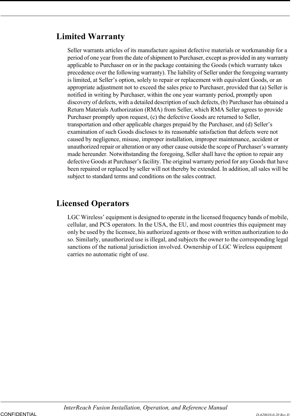

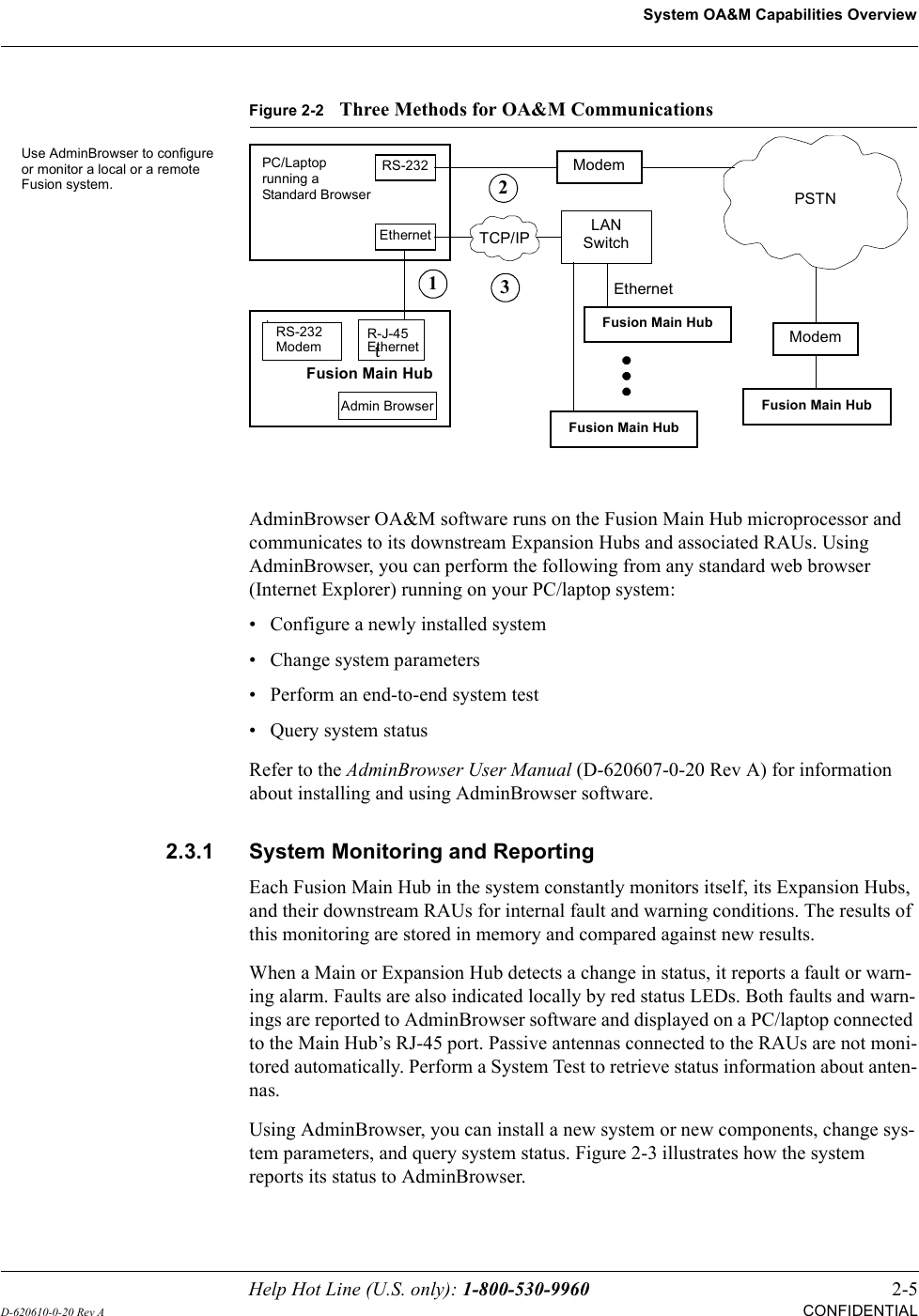
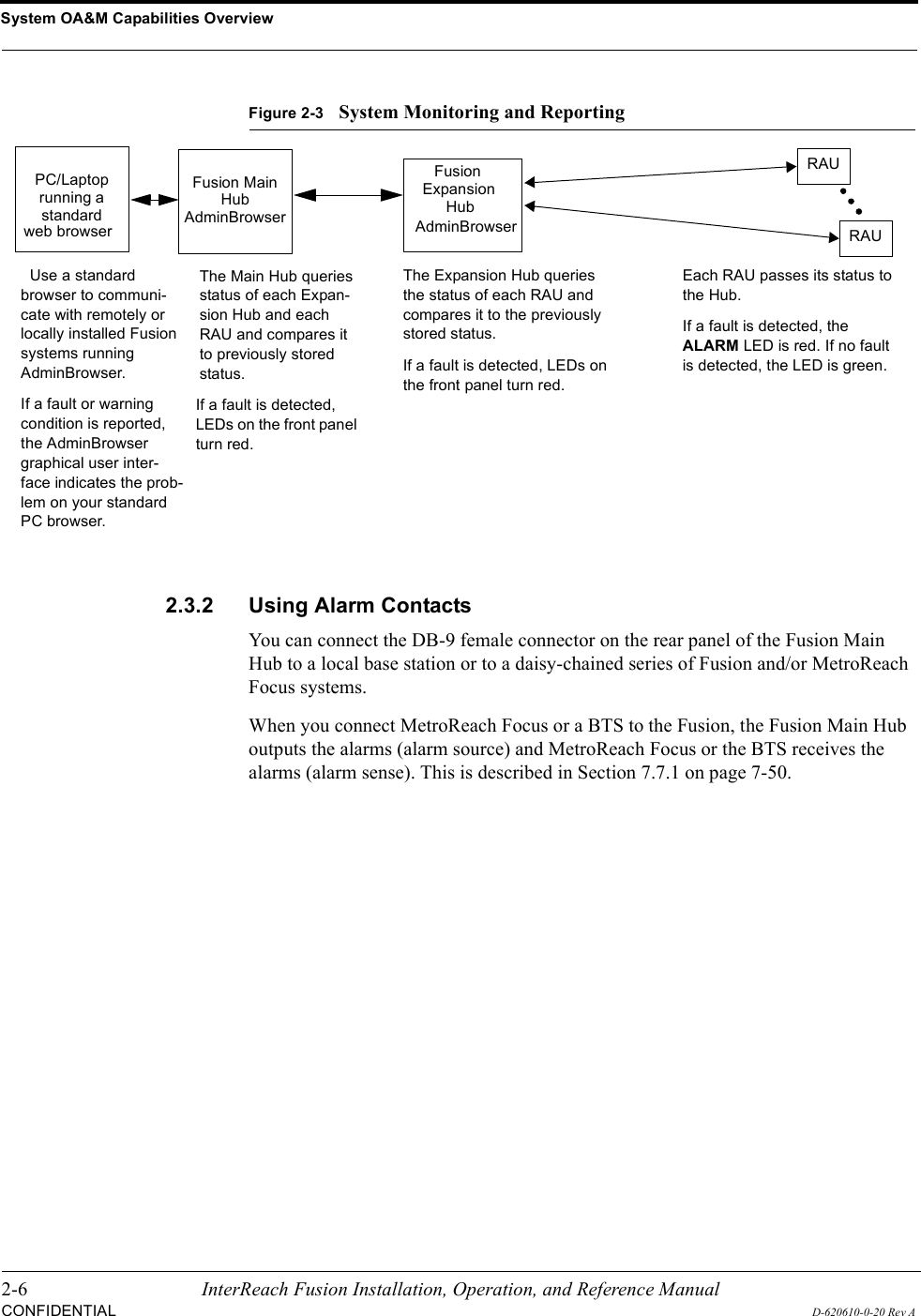
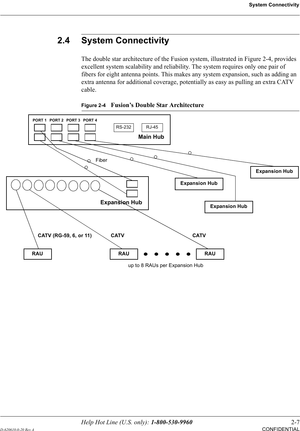
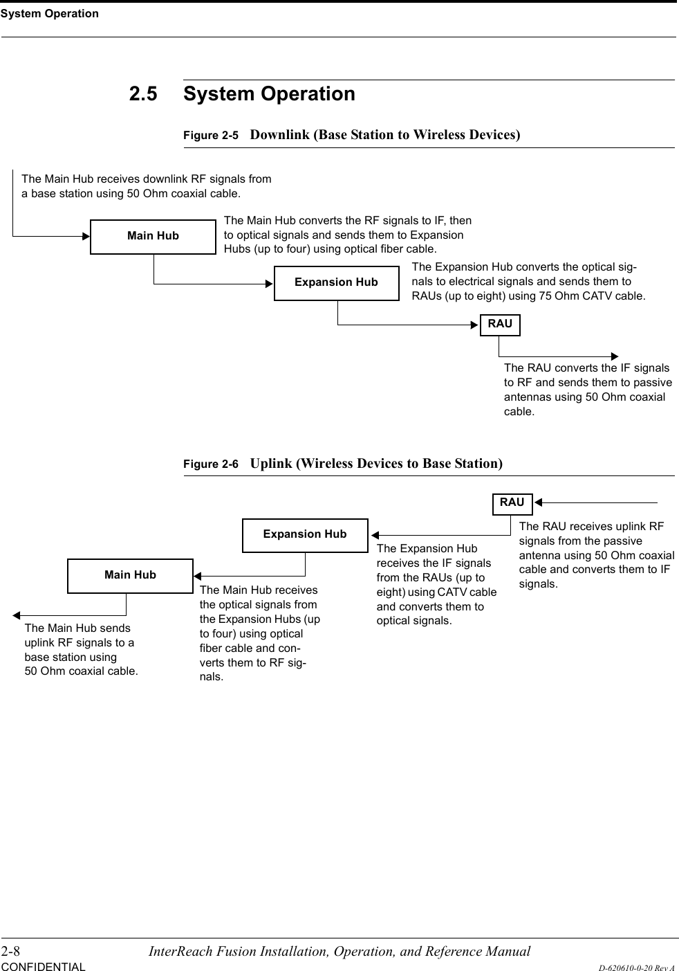
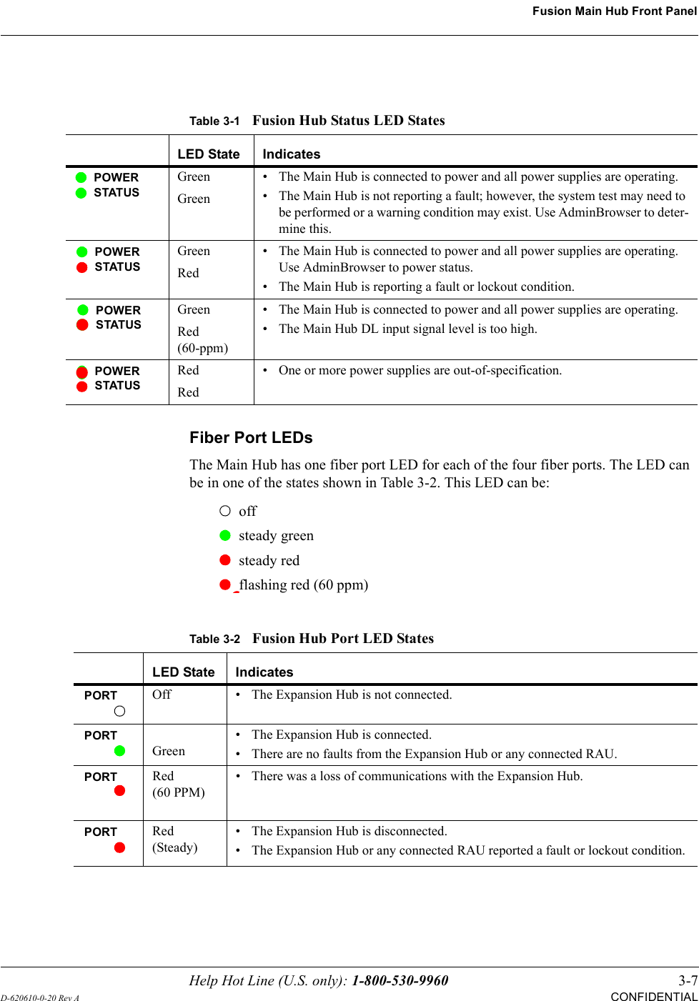
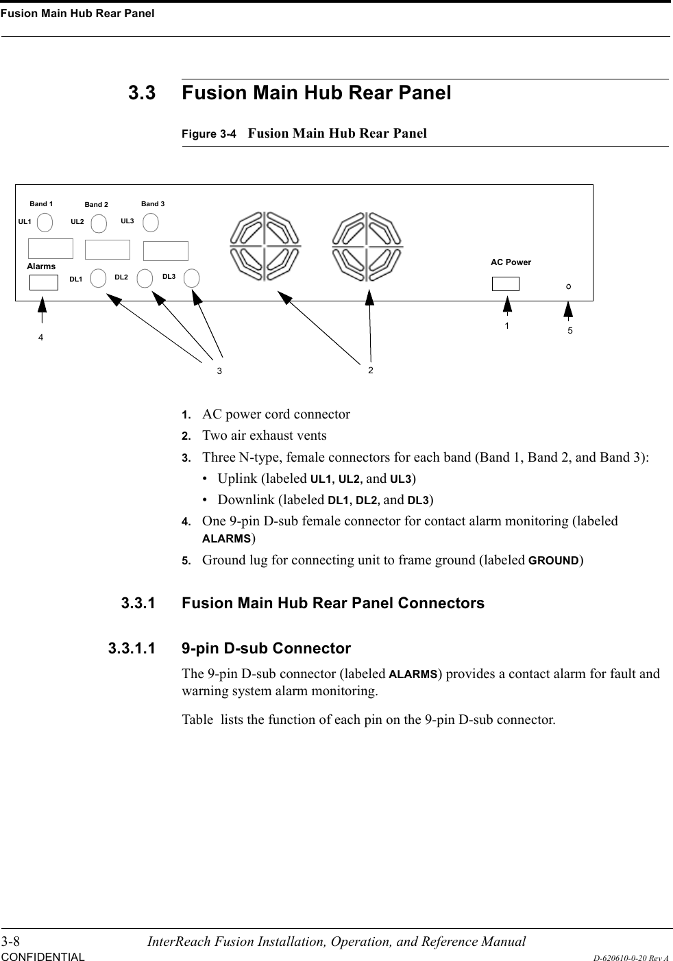
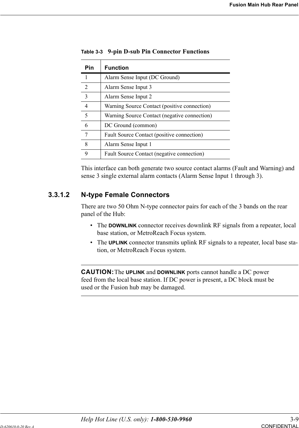
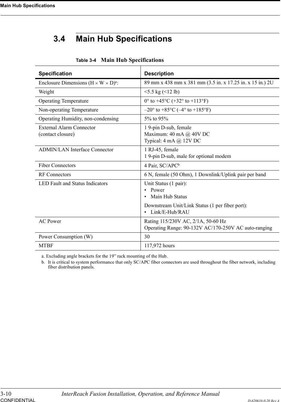
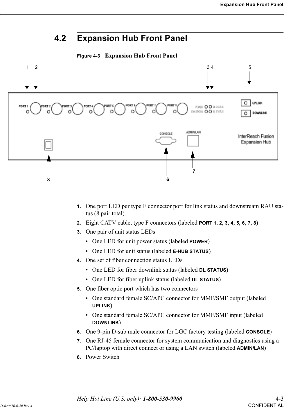
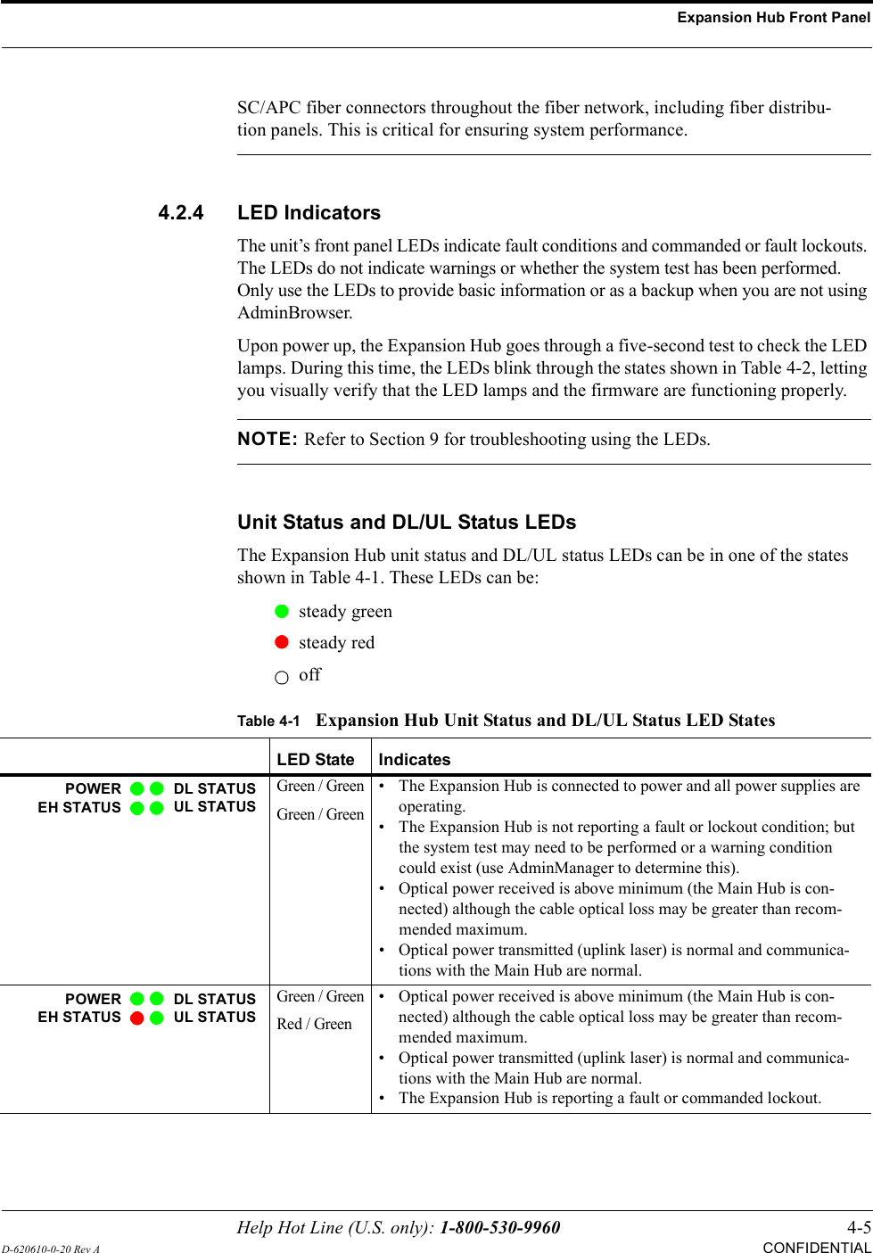
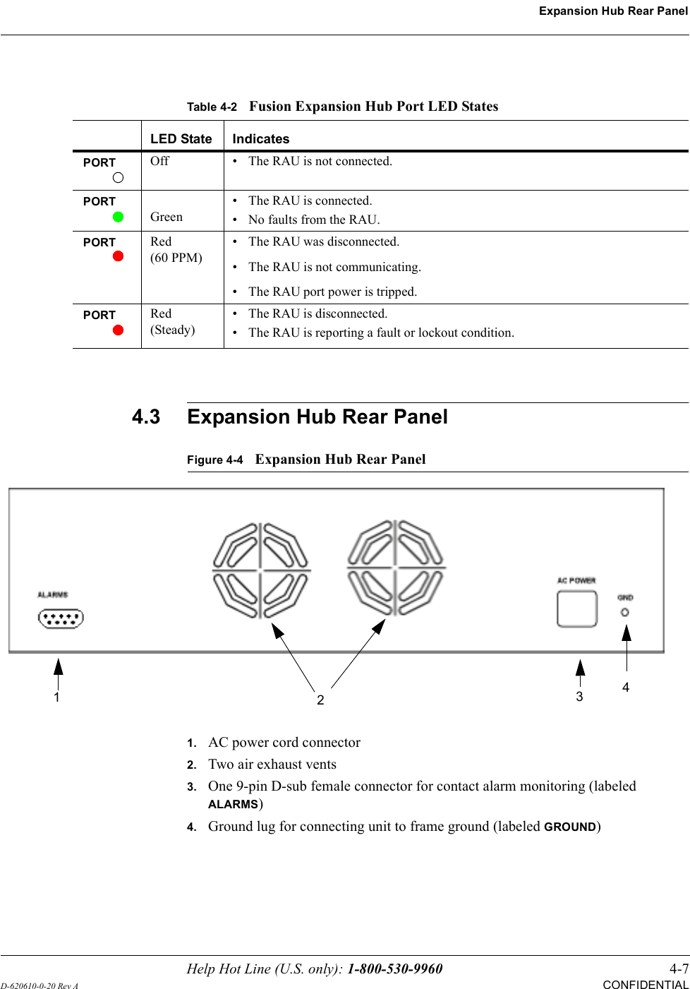
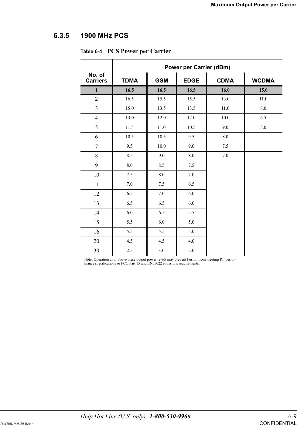
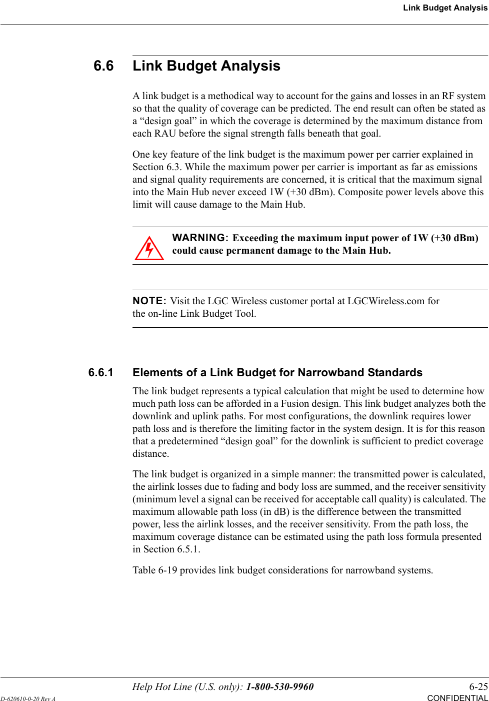
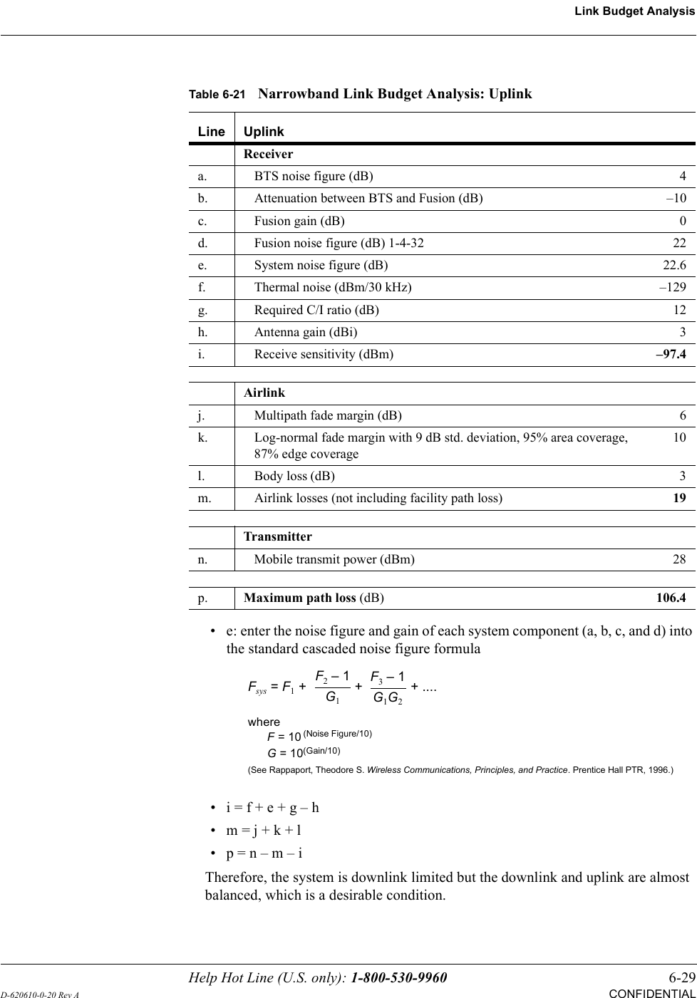
![Expansion Hub Front Panel4-6 InterReach Fusion Installation, Operation, and Reference ManualCONFIDENTIALD-620610-0-20 Rev ARJ-45 Port LEDsThe Expansion Hub has a port LED, labeled PORT, for each of the eight 75 Ohm, Type F ports. The port LEDs can be in one of the states shown in Table 4-2. These LEDs can be:offsteady greensteady redflashing red (60 pulses per minute [PPM])Green / RedRed / Green• A fault condition was detected, optical power received is below mini-mum. (the Main Hub is not connected, is not powered, or the Main Hub’s downlink laser has failed, or the downlink fiber is disconnected or damaged.)Green / GreenRed / Red• The Expansion Hub is reporting a fault condition.• Optical power received is above minimum (Main Hub is connected) although the cable optical loss may be greater than recommended maximum.• Optical power transmitted is below minimum (Expansion Hub uplink laser has failed; unable to communicate with Main Hub). UL STATUS LED state must be checked within the first 90 seconds after power on. If initially green, then red after 90 seconds, it means that there is no communication with the Main Hub. If red on power up, replace the Expansion Hub.Green / RedRed / Red• Optical power received is below minimum (the Main Hub is not con-nected, is not powered, or the Main Hub’s downlink laser has failed, or the downlink fiber is disconnected or damaged.)• Optical power transmitted is below minimum (the Expansion Hub uplink laser has failed; is unable to communicate with the Main Hub). UL STATUS LED state must be checked within the first 90 seconds after power on. If initially green, then red after 90 seconds, it means that there is no communication with the Main Hub. If red on power up, the uplink laser has failed, replace the Expansion Hub.Green /OffGreen / Off• Expansion Hub is in factory test mode, return it to the factory.Red/ Don’t CareRed/ Don’t Care• One or more power supplies are out of specification. The hub needs to be replaced.Green/ RedOff/ Off• Expansion Hub failure. The Hub must be replaced.Table 4-1Expansion Hub Unit Status and DL/UL Status LED States (continued)LED State IndicatesPOWEREH STATUSDL STATUSUL STATUSPOWEREH STATUSDL STATUSUL STATUSPOWEREH STATUSDL STATUSUL STATUSPOWEREH STATUSDL STATUSUL STATUSPOWEREH STATUSDL STATUSUL STATUSPOWEREH STATUSDL STATUSUL STATUS](https://usermanual.wiki/ADC-Telecommunications/FSN-809019-2.User-Manual-Part-One/User-Guide-869345-Page-52.png)