ADC Telecommunications FSN-809019-2 InterReach Fusion FSN-809019-2 User Manual fusionBOOK
ADC Telecommunications Inc. InterReach Fusion FSN-809019-2 fusionBOOK
Contents
- 1. User Manual Part One
- 2. User Manual Part Two
User Manual Part One
D-620610-0-20
Rev A
Installation, Operation, and Reference Manual
InterReach Fusion
TM
®

D-620610-0-20
Help Hot Line (U.S. only): 1-800-530-9960
Rev A
CONFIDENTIAL

D-620610-0-20
Help Hot Line (U.S. only): 1-800-530-9960
Rev A
CONFIDENTIAL
This manual is produced for use by LGC Wireless personnel, licensees, and customers. The
information contained herein is the property of LGC Wireless. No part of this document
may be reproduced or transmitted in any form or by any means, electronic or mechanical,
for any purpose, without the express written permission of LGC Wireless.
LGC Wireless reserves the right to make changes, without notice, to the specifications and
materials contained herein, and shall not be responsible for any damages caused by reliance
on the material as presented, including, but not limited to, typographical and listing errors.
Your comments are welcome – they help us improve our products and documentation.
Please address your comments to LGC Wireless, Inc. corporate headquarters in San Jose,
California:
Address 2540 Junction Avenue
San Jose, California
95134-1902 USA
Attn: Marketing Dept.
Phone 1-408-952-2400
Fax 1-408-952-2410
Help Hot Line 1-800-530-9960 (U.S. only)
+1-408-952-2400 (International)
Web Address http://www.lgcwireless.com
e-mail info@lgcwireless.com
service@lgcwireless.com
Copyright © 2006 by LGC Wireless, Inc. Printed in USA. All rights reserved.
Trademarks
All trademarks identified by ™
or ® are trademarks or registered trademarks of LGC
Wireless, Inc. All other trademarks belong to their respective owners.

InterReach Fusion Installation, Operation, and Reference Manual
CONFIDENTIAL
D-620610-0-20 Rev D
Limited Warranty
Seller warrants articles of its manufacture against defective materials or workmanship for a
period of one year from the date of shipment to Purchaser, except as provided in any warranty
applicable to Purchaser on or in the package containing the Goods (which warranty takes
precedence over the following warranty). The liability of Seller under the foregoing warranty
is limited, at Seller’s option, solely to repair or replacement with equivalent Goods, or an
appropriate adjustment not to exceed the sales price to Purchaser, provided that (a) Seller is
notified in writing by Purchaser, within the one year warranty period, promptly upon
discovery of defects, with a detailed description of such defects, (b) Purchaser has obtained a
Return Materials Authorization (RMA) from Seller, which RMA Seller agrees to provide
Purchaser promptly upon request, (c) the defective Goods are returned to Seller,
transportation and other applicable charges prepaid by the Purchaser, and (d) Seller’s
examination of such Goods discloses to its reasonable satisfaction that defects were not
caused by negligence, misuse, improper installation, improper maintenance, accident or
unauthorized repair or alteration or any other cause outside the scope of Purchaser’s warranty
made hereunder. Notwithstanding the foregoing, Seller shall have the option to repair any
defective Goods at Purchaser’s facility. The original warranty period for any Goods that have
been repaired or replaced by seller will not thereby be extended. In addition, all sales will be
subject to standard terms and conditions on the sales contract.
Licensed Operators
LGC Wireless’ equipment is designed to operate in the licensed frequency bands of mobile,
cellular, and PCS operators. In the USA, the EU, and most countries this equipment may
only be used by the licensee, his authorized agents or those with written authorization to do
so. Similarly, unauthorized use is illegal, and subjects the owner to the corresponding legal
sanctions of the national jurisdiction involved. Ownership of LGC Wireless equipment
carries no automatic right of use.

InterReach Fusion Installation, Operation, and Reference Manual 1
D-620610-0-20 Rev A
CONFIDENTIAL
Table of Contents
SECTION 1
General Information . . . . . . . . . . . . . . . . . . . . . . 1-1
1.1 Firmware Release . . . . . . . . . . . . . . . . . . . . . . . . . . . . . . . . . . 1-1
1.2 Purpose and Scope . . . . . . . . . . . . . . . . . . . . . . . . . . . . . . . . . 1-1
1.3 Conventions in this Manual . . . . . . . . . . . . . . . . . . . . . . . . . . 1-2
1.4 Standards Conformance . . . . . . . . . . . . . . . . . . . . . . . . . . . . . 1-3
1.5 Related Publications . . . . . . . . . . . . . . . . . . . . . . . . . . . . . . . . 1-3
SECTION 2
InterReach Fusion
System Description . . . . . . . . . . . . . . . . . . . . . . 2-1
2.1 System Overview . . . . . . . . . . . . . . . . . . . . . . . . . . . . . . . . . . 2-1
2.2 System Hardware Description . . . . . . . . . . . . . . . . . . . . . . . . 2-3
2.3 System OA&M Capabilities Overview . . . . . . . . . . . . . . . . . 2-4
2.3.1 System Monitoring and Reporting . . . . . . . . . . . . . . . . . . . . . 2-5
2.3.2 Using Alarm Contacts . . . . . . . . . . . . . . . . . . . . . . . . . . . . . . . 2-6
2.4 System Connectivity . . . . . . . . . . . . . . . . . . . . . . . . . . . . . . . . 2-7
2.5 System Operation . . . . . . . . . . . . . . . . . . . . . . . . . . . . . . . . . . 2-8
2.6 System Specifications . . . . . . . . . . . . . . . . . . . . . . . . . . . . . . . 2-9
2.6.1 RF End-to-End Performance . . . . . . . . . . . . . . . . . . . . . . . . . 2-11
SECTION 3
Fusion Main Hub . . . . . . . . . . . . . . . . . . . . . . . . . 3-1
3.1 Fusion Main Hub Overview . . . . . . . . . . . . . . . . . . . . . . . . . . 3-1
3.2 Fusion Main Hub Front Panel . . . . . . . . . . . . . . . . . . . . . . . . . 3-4
3.2.1 Optical Fiber Uplink/Downlink Ports . . . . . . . . . . . . . . . . . . . 3-5
3.2.2 Communications RS-232 Serial Connector . . . . . . . . . . . . . . 3-5
3.2.3 Main Hub LED Indicators . . . . . . . . . . . . . . . . . . . . . . . . . . . . 3-5
3.3 Fusion Main Hub Rear Panel . . . . . . . . . . . . . . . . . . . . . . . . . 3-8
3.3.1 Fusion Main Hub Rear Panel Connectors . . . . . . . . . . . . . . . . 3-8
3.3.1.1 9-pin D-sub Connector . . . . . . . . . . . . . . . . . . . . . . . . . 3-8
3.3.1.2 N-type Female Connectors . . . . . . . . . . . . . . . . . . . . . . 3-9
3.4 Main Hub Specifications . . . . . . . . . . . . . . . . . . . . . . . . . . . 3-10
3.5 Faults, Warnings, and Status Messages . . . . . . . . . . . . . . . . 3-11

CONFIDENTIAL
2InterReach Fusion Installation, Operation, and Reference Manual
D-620610-0-20 Rev A
3.5.1 Description . . . . . . . . . . . . . . . . . . . . . . . . . . . . . . . . . . . . . . . 3-11
3.5.2 View Preference . . . . . . . . . . . . . . . . . . . . . . . . . . . . . . . . . . . 3-12
SECTION 4
Fusion Expansion Hub . . . . . . . . . . . . . . . . . . . . 4-1
4.1 Expansion Hub Overview . . . . . . . . . . . . . . . . . . . . . . . . . . . . 4-1
4.2 Expansion Hub Front Panel . . . . . . . . . . . . . . . . . . . . . . . . . . 4-3
4.2.1 75 Ohm Type F Connectors . . . . . . . . . . . . . . . . . . . . . . . . . . . 4-4
4.2.2 Manufacturing RS-232 Serial Connector . . . . . . . . . . . . . . . . 4-4
4.2.3 Optical Fiber Uplink/Downlink Connectors . . . . . . . . . . . . . . 4-4
4.2.4 LED Indicators . . . . . . . . . . . . . . . . . . . . . . . . . . . . . . . . . . . . . 4-5
4.3 Expansion Hub Rear Panel . . . . . . . . . . . . . . . . . . . . . . . . . . . 4-7
4.4 Faults, Warnings, and Status Messages . . . . . . . . . . . . . . . . . . 4-8
4.5 Expansion Hub Specifications . . . . . . . . . . . . . . . . . . . . . . . . 4-9
SECTION 5
Remote Access Unit . . . . . . . . . . . . . . . . . . . . . . 5-1
5.1 RAU Overview . . . . . . . . . . . . . . . . . . . . . . . . . . . . . . . . . . . . 5-1
5.2 Remote Access Unit Connectors . . . . . . . . . . . . . . . . . . . . . . . 5-5
5.2.1 50 Ohm Type-N Connector . . . . . . . . . . . . . . . . . . . . . . . . . . . 5-5
5.2.2 75 Ohm Type-F Connector . . . . . . . . . . . . . . . . . . . . . . . . . . . 5-5
5.3 RAU LED Indicators . . . . . . . . . . . . . . . . . . . . . . . . . . . . . . . 5-6
5.4 Faults and Warnings . . . . . . . . . . . . . . . . . . . . . . . . . . . . . . . . 5-7
5.5 Remote Access Unit Specifications . . . . . . . . . . . . . . . . . . . . 5-7
SECTION 6
Designing a Fusion Solution . . . . . . . . . . . . . . . 6-1
6.1 Overview . . . . . . . . . . . . . . . . . . . . . . . . . . . . . . . . . . . . . . . . . 6-1
6.2 Downlink RSSI Design Goal . . . . . . . . . . . . . . . . . . . . . . . . . 6-3
6.3 Maximum Output Power per Carrier . . . . . . . . . . . . . . . . . . . 6-4
6.3.1 850 MHz Cellular . . . . . . . . . . . . . . . . . . . . . . . . . . . . . . . . . . 6-5
6.3.2 800 MHz or 900 MHz SMR . . . . . . . . . . . . . . . . . . . . . . . . . . 6-6
6.3.3 900 MHz EGSM and EDGE . . . . . . . . . . . . . . . . . . . . . . . . . . 6-7
6.3.4 1800 MHz DCS . . . . . . . . . . . . . . . . . . . . . . . . . . . . . . . . . . . . 6-8
6.3.5 1900 MHz PCS . . . . . . . . . . . . . . . . . . . . . . . . . . . . . . . . . . . . 6-9
6.3.6 2.1 GHz UMTS . . . . . . . . . . . . . . . . . . . . . . . . . . . . . . . . . . . 6-10
6.4 System Gain . . . . . . . . . . . . . . . . . . . . . . . . . . . . . . . . . . . . . 6-11
6.5 Estimating RF Coverage . . . . . . . . . . . . . . . . . . . . . . . . . . . . 6-14
6.5.1 Path Loss Equation . . . . . . . . . . . . . . . . . . . . . . . . . . . . . . . . 6-15
6.5.2 RAU Coverage Distance . . . . . . . . . . . . . . . . . . . . . . . . . . . . 6-16
6.5.3 Examples of Design Estimates . . . . . . . . . . . . . . . . . . . . . . . 6-21
6.6 Link Budget Analysis . . . . . . . . . . . . . . . . . . . . . . . . . . . . . . 6-25
6.6.1 Elements of a Link Budget for Narrowband Standards . . . . . 6-25
6.6.2 Narrowband Link Budget Analysis
for a Microcell Application . . . . . . . . . . . . . . . . . . . . . . . . . . 6-28
6.6.3 Elements of a Link Budget for CDMA Standards . . . . . . . . . 6-30
6.6.4 CDMA Link Budget Analysis for a Microcell Application . 6-33

CONFIDENTIAL
InterReach Fusion Installation, Operation, and Reference Manual 3
D-620610-0-20 Rev A
6.6.5 Considerations for Re-Radiation (Over-the-Air) Systems . . 6-36
6.7 Optical Power Budget . . . . . . . . . . . . . . . . . . . . . . . . . . . . . . 6-37
6.8 Connecting a Main Hub to a Base Station . . . . . . . . . . . . . . 6-38
6.8.1 Uplink Attenuation . . . . . . . . . . . . . . . . . . . . . . . . . . . . . . . . 6-38
6.8.2 RAU Attenuation and ALC . . . . . . . . . . . . . . . . . . . . . . . . . . 6-39
6.8.2.1 Using the RAU 10 dB Attenuation Setting . . . . . . . . . 6-40
6.8.2.2 Using the Uplink ALC Setting . . . . . . . . . . . . . . . . . . 6-41
SECTION 7
Installing Fusion . . . . . . . . . . . . . . . . . . . . . . . . . 7-1
7.1 Installation Requirements . . . . . . . . . . . . . . . . . . . . . . . . . . . . 7-1
7.1.1 Component Location Requirements . . . . . . . . . . . . . . . . . . . . 7-2
7.1.2 Cable and Connector Requirements . . . . . . . . . . . . . . . . . . . . 7-2
7.1.3 Distance Requirements . . . . . . . . . . . . . . . . . . . . . . . . . . . . . . 7-3
7.2 Safety Precautions . . . . . . . . . . . . . . . . . . . . . . . . . . . . . . . . . 7-3
7.2.1 Installation Guidelines . . . . . . . . . . . . . . . . . . . . . . . . . . . . . . . 7-3
7.2.2 General Safety Precautions . . . . . . . . . . . . . . . . . . . . . . . . . . . 7-4
7.2.3 Fiber Port Safety Precautions . . . . . . . . . . . . . . . . . . . . . . . . . 7-5
7.3 Preparing for System Installation . . . . . . . . . . . . . . . . . . . . . . 7-6
7.3.1 Pre-Installation Inspection . . . . . . . . . . . . . . . . . . . . . . . . . . . . 7-6
7.3.2 Installation Checklist . . . . . . . . . . . . . . . . . . . . . . . . . . . . . . . . 7-6
7.3.3 Tools and Materials Required . . . . . . . . . . . . . . . . . . . . . . . . . 7-8
7.3.4 Optional Accessories . . . . . . . . . . . . . . . . . . . . . . . . . . . . . . . . 7-9
7.4 Fusion Installation Procedures . . . . . . . . . . . . . . . . . . . . . . . 7-10
7.4.1 Installing a Fusion Main Hub . . . . . . . . . . . . . . . . . . . . . . . . 7-11
7.4.2 Installing Expansion Hubs . . . . . . . . . . . . . . . . . . . . . . . . . . . 7-20
7.4.3 Installing RAUs . . . . . . . . . . . . . . . . . . . . . . . . . . . . . . . . . . . 7-27
7.4.3.1 Troubleshooting Using RAU LEDs
During Installation . . . . . . . . . . . . . . . . . . . . . . . . . . . . 7-30
7.4.3.2 Installing RAUs in a Multiple Operator System . . . . . 7-31
7.4.4 Configuring the System . . . . . . . . . . . . . . . . . . . . . . . . . . . . . 7-31
7.5 Splicing Fiber Optic Cable . . . . . . . . . . . . . . . . . . . . . . . . . . 7-37
7.6 Interfacing the Fusion Main Hub to an RF Source . . . . . . . . 7-39
7.6.1 Connecting a Single Fusion Main Hub to an RF Source . . . 7-39
7.6.2 Connecting Multiple Fusion Main Hubs to an RF Source . . 7-44
7.7 Connecting Contact Alarms to a Fusion System . . . . . . . . . 7-49
7.7.1 Alarm Source . . . . . . . . . . . . . . . . . . . . . . . . . . . . . . . . . . . . . 7-50
7.7.2 Alarm Sense . . . . . . . . . . . . . . . . . . . . . . . . . . . . . . . . . . . . . 7-53
7.7.3 Alarm Cables . . . . . . . . . . . . . . . . . . . . . . . . . . . . . . . . . . . . . 7-55
7.8 Alarm Monitoring Connectivity Options . . . . . . . . . . . . . . . 7-57
7.8.1 Direct Connection . . . . . . . . . . . . . . . . . . . . . . . . . . . . . . . . . 7-57
7.8.2 Modem Connection . . . . . . . . . . . . . . . . . . . . . . . . . . . . . . . . 7-58
7.8.2.1 Setting Up Fusion Modem Using AdminBrowser . . . 7-58
7.8.2.2 Setting Up a PC Modem Using Windows . . . . . . . . . . 7-59
7.8.3 100 BASE-T Port Expander Connection . . . . . . . . . . . . . . . . 7-67
7.8.4 POTS Line Sharing Switch Connection . . . . . . . . . . . . . . . . 7-68
7.8.5 Ethernet LAN Connection . . . . . . . . . . . . . . . . . . . . . . . . . . . 7-70

CONFIDENTIAL
4InterReach Fusion Installation, Operation, and Reference Manual
D-620610-0-20 Rev A
7.8.6 SNMP Interface . . . . . . . . . . . . . . . . . . . . . . . . . . . . . . . . . . . 7-71
SECTION 8
Replacing Fusion Components . . . . . . . . . . . . . 8-1
8.1 Replacing an RAU . . . . . . . . . . . . . . . . . . . . . . . . . . . . . . . . . 8-1
8.2 Replacing a Fusion Expansion Hub . . . . . . . . . . . . . . . . . . . . 8-3
8.3 Replacing a Fusion Main Hub . . . . . . . . . . . . . . . . . . . . . . . . 8-4
SECTION 9
Maintenance, Troubleshooting, and Technical
Assistance 9-1
9.1 Service . . . . . . . . . . . . . . . . . . . . . . . . . . . . . . . . . . . . . . . . . . . 9-1
9.2 Maintenance . . . . . . . . . . . . . . . . . . . . . . . . . . . . . . . . . . . . . . 9-2
9.3 Troubleshooting . . . . . . . . . . . . . . . . . . . . . . . . . . . . . . . . . . . 9-3
9.3.1 Troubleshooting Using AdminBrowser . . . . . . . . . . . . . . . . . . 9-4
9.3.1.1 Troubleshooting Recommendations . . . . . . . . . . . . . . . 9-4
9.3.1.2 Fault/Warning/Status Indications . . . . . . . . . . . . . . . . . . 9-5
9.3.2 Troubleshooting Using LEDs . . . . . . . . . . . . . . . . . . . . . . . . . 9-5
9.4 Troubleshooting CATV . . . . . . . . . . . . . . . . . . . . . . . . . . . . . 9-10
9.5 Technical Assistance . . . . . . . . . . . . . . . . . . . . . . . . . . . . . . . 9-10
APPENDIX A
Cables and Connectors . . . . . . . . . . . . . . . . . . . A-1
A.1 75 Ohm CATV Cable . . . . . . . . . . . . . . . . . . . . . . . . . . . . . . .A-1
A.2 Fiber Optical Cables . . . . . . . . . . . . . . . . . . . . . . . . . . . . . . . .A-8
A.3 Coaxial Cable . . . . . . . . . . . . . . . . . . . . . . . . . . . . . . . . . . . . .A-8
A.4 Standard Modem Cable . . . . . . . . . . . . . . . . . . . . . . . . . . . . . . A-9
A.5 TCP/IP Cross-over Cable . . . . . . . . . . . . . . . . . . . . . . . . . . . A-10
A.6 DB-25 to DB-9 Null Modem Cable . . . . . . . . . . . . . . . . . . . A-11
APPENDIX B
Compliance . . . . . . . . . . . . . . . . . . . . . . . . . . . . . B-1
B.1 Fusion System Approval Status . . . . . . . . . . . . . . . . . . . . . . . B-1
B.2 Human Exposure to RF . . . . . . . . . . . . . . . . . . . . . . . . . . . . . . B-3
APPENDIX C
Faults, Warnings, Status Tables . . . . . . . . . . . . C-1
C.1 Faults Reported by Fusion Main/SingleStar Hubs . . . . . . . . . C-1
C.2 Faults Reported for System CPU . . . . . . . . . . . . . . . . . . . . . . C-5
C.3 Faults for Fusion Expansion Hubs . . . . . . . . . . . . . . . . . . . . . C-6
C.4 Faults for RAUs . . . . . . . . . . . . . . . . . . . . . . . . . . . . . . . . . . . C-9
C.5 Warning/Status Messages for Fusion Main/Singlestar Hubs C-10
C.6 Warning/Status Messages for System CPUs . . . . . . . . . . . . . C-15
C.7 Warning/Status Messages for Fusion Expansion Hubs . . . . . C-16
C.8 Warning /Status Messages for RAUs . . . . . . . . . . . . . . . . . . C-19

CONFIDENTIAL
InterReach Fusion Installation, Operation, and Reference Manual 1
D-620610-0-20 Rev A
List of Figures
Figure 2-1 Fusion System Hardware . . . . . . . . . . . . . . . . . . . . . . . . . . . . . . . . . .2-4
Figure 2-2 Three Methods for OA&M Communications . . . . . . . . . . . . . . . . . .2-5
Figure 2-3 System Monitoring and Reporting . . . . . . . . . . . . . . . . . . . . . . . . . .2-6
Figure 2-4 Fusion’s Double Star Architecture . . . . . . . . . . . . . . . . . . . . . . . . . . .2-7
Figure 2-5 Downlink (Base Station to Wireless Devices) . . . . . . . . . . . . . . . . . .2-8
Figure 2-6 Uplink (Wireless Devices to Base Station) . . . . . . . . . . . . . . . . . . . .2-8
Figure 3-1 Main Hub in a Fusion System . . . . . . . . . . . . . . . . . . . . . . . . . . . . . .3-2
Figure 3-2 Main Hub Block Diagram . . . . . . . . . . . . . . . . . . . . . . . . . . . . . . . . .3-3
Figure 3-3 Fusion Main Hub Front Panel . . . . . . . . . . . . . . . . . . . . . . . . . . . . . .3-4
Figure 3-4 Fusion Main Hub Rear Panel . . . . . . . . . . . . . . . . . . . . . . . . . . . . . . .3-8
Figure 3-5 Preferences Check Boxes . . . . . . . . . . . . . . . . . . . . . . . . . . . . . . . . .3-12
Figure 4-1 Expansion Hub in a Fusion System . . . . . . . . . . . . . . . . . . . . . . . . . .4-1
Figure 4-2 Expansion Hub Block Diagram . . . . . . . . . . . . . . . . . . . . . . . . . . . . .4-2
Figure 4-3 Expansion Hub Front Panel . . . . . . . . . . . . . . . . . . . . . . . . . . . . . . . .4-3
Figure 4-4 Expansion Hub Rear Panel . . . . . . . . . . . . . . . . . . . . . . . . . . . . . . . . .4-7
Figure 5-1 Remote Access Unit in a Fusion System . . . . . . . . . . . . . . . . . . . . . .5-2
Figure 5-2 Remote Access Unit Block Diagram (Multiband) . . . . . . . . . . . . . . .5-2
Figure 6-1 Determining APL between the Antenna and the Wireless Device .6-14
Figure 6-2 ALC Operation . . . . . . . . . . . . . . . . . . . . . . . . . . . . . . . . . . . . . . . . .6-40
Figure 7-1 Flush Mounting Bracket Detail . . . . . . . . . . . . . . . . . . . . . . . . . . . .7-12
Figure 7-2 Bracket Detail For Wall Mount Rack (PN 4712) . . . . . . . . . . . . . . .7-13
Figure 7-3 Installing Directly to the Wall . . . . . . . . . . . . . . . . . . . . . . . . . . . . .7-14
Figure 7-4 Using Hub Rack-Mounting Brackets for Direct Wall Installation . .7-15

CONFIDENTIAL
2InterReach Fusion Installation, Operation, and Reference Manual
D-620610-0-20 Rev A
Figure 7-5 Flush Mounting Bracket Detail . . . . . . . . . . . . . . . . . . . . . . . . . . . 7-20
Figure 7-6 Bracket Detail For Wall Mount Rack (PN 4712) . . . . . . . . . . . . . . 7-21
Figure 7-7 Using Hub Rack-Mounting Brackets for Direct Wall Installation . 7-22
Figure 7-8 Installing Directly to the Wall . . . . . . . . . . . . . . . . . . . . . . . . . . . . 7-23
Figure 7-9 800/850 MHz Spectrum . . . . . . . . . . . . . . . . . . . . . . . . . . . . . . . . . 7-28
Figure 7-10 Guideline for Unison RAU Antenna Placement . . . . . . . . . . . . . . 7-28
Figure 7-11 Internet Protocol (TCP/IP) Properties Window . . . . . . . . . . . . . . . 7-32
Figure 7-12 Local Area Connection Properties Window . . . . . . . . . . . . . . . . . . 7-33
Figure 7-13 Set Time and Date Window . . . . . . . . . . . . . . . . . . . . . . . . . . . . . . 7-34
Figure 7-14 AdminBrowser Configuration Window . . . . . . . . . . . . . . . . . . . . . 7-34
Figure 7-15 AdminBrowser Configuration Window (continued) . . . . . . . . . . . 7-35
Figure 7-16 Simplex Base Station to a Fusion Main Hub . . . . . . . . . . . . . . . . . 7-40
Figure 7-17 Duplex Base Station to a Fusion Main Hub . . . . . . . . . . . . . . . . . 7-41
Figure 7-18 Connecting a Fusion Main Hub to Multiple Base Stations . . . . . . 7-42
Figure 7-19 Connecting a Fusion Main Hub to a Roof-top Antenna . . . . . . . . . 7-43
Figure 7-20 Connecting Two Fusion Main Hub’s RF Band Ports
to a Simplex Repeater or Base Station . . . . . . . . . . . . . . . . . . . . . 7-46
Figure 7-21 Connecting Two Fusion Main Hub’s RF Band Ports
to a Duplex Repeater or Base Station . . . . . . . . . . . . . . . . . . . . . . 7-48
Figure 7-22 Connecting MetroReach to Fusion . . . . . . . . . . . . . . . . . . . . . . . . 7-50
Figure 7-23 Using a BTS to Monitor Fusion . . . . . . . . . . . . . . . . . . . . . . . . . . 7-51
Figure 7-24 Using a BTS and AdminBrowser to Monitor Fusion . . . . . . . . . . . 7-52
Figure 7-25 Using Fusion to Monitor Unison . . . . . . . . . . . . . . . . . . . . . . . . . . 7-53
Figure 7-26 Alarm Sense Contacts . . . . . . . . . . . . . . . . . . . . . . . . . . . . . . . . . . . 7-54
Figure 7-27 5-port Alarm Daisy-Chain Cable . . . . . . . . . . . . . . . . . . . . . . . . . . 7-55
Figure 7-28 Alarm Sense Adapter Cable . . . . . . . . . . . . . . . . . . . . . . . . . . . . . . 7-56
Figure 7-29 OA&M Direct Connection . . . . . . . . . . . . . . . . . . . . . . . . . . . . . . . 7-57
Figure 7-30 OA&M Modem Connection . . . . . . . . . . . . . . . . . . . . . . . . . . . . . 7-58
Figure 7-31 Default Dial-in Settings (Fusion Hub) . . . . . . . . . . . . . . . . . . . . . . 7-59
Figure 7-32 Network Connections Window . . . . . . . . . . . . . . . . . . . . . . . . . . . 7-60
Figure 7-33 New Connection Wizard - Welcome Window . . . . . . . . . . . . . . . . 7-60
Figure 7-34 New Connection Wizard - Network Connection Type Window . . 7-61
Figure 7-35 New Connection Wizard - Network Connection Window . . . . . . . 7-61
Figure 7-36 New Connection Wizard - Connection Name Window . . . . . . . . . 7-62
Figure 7-37 New Connection Wizard - Phone Number to Dial Window . . . . . 7-62
Figure 7-38 New Connection Wizard - Connection Availability Window . . . . 7-63
Figure 7-39 New Connection Wizard - Completing New Connection Window 7-63
Figure 7-40 Connect Fusion Hub Window . . . . . . . . . . . . . . . . . . . . . . . . . . . . 7-64
Figure 7-41 Fusion Hub Properties Window . . . . . . . . . . . . . . . . . . . . . . . . . . . 7-64

CONFIDENTIAL
InterReach Fusion Installation, Operation, and Reference Manual 3
D-620610-0-20 Rev A
Figure 7-42 Modem Configuration Window . . . . . . . . . . . . . . . . . . . . . . . . . . . .7-65
Figure 7-43 Fusion Hub Properties - Security Tab Window . . . . . . . . . . . . . . . .7-65
Figure 7-44 Fusion Hub Properties - Networking Tab Window . . . . . . . . . . . . .7-66
Figure 7-45 Internet Protocol Properties Window . . . . . . . . . . . . . . . . . . . . . . . .7-66
Figure 7-46 OA&M Connection using a 232 Port Expander . . . . . . . . . . . . . . .7-67
Figure 7-47 OA&M Connection Using a POTS Line Sharing Switch . . . . . . . .7-68
Figure 7-48 Cascading Line Sharing Switches . . . . . . . . . . . . . . . . . . . . . . . . . .7-69
Figure 7-49 OA&M Connection Using Ethernet and ENET/232 Serial Hub . . .7-70
Figure 7-50 Fusion SNMP Configuration Options . . . . . . . . . . . . . . . . . . . . . . .7-71
Figure A-1 CommScope 2065V for RG-59 . . . . . . . . . . . . . . . . . . . . . . . . . . . . A-2
Figure A-2 CommScope 2279V for RG-6 . . . . . . . . . . . . . . . . . . . . . . . . . . . . . A-3
Figure A-3 CommScope 2293K for RG-11 . . . . . . . . . . . . . . . . . . . . . . . . . . . . A-4
Figure A-1 Standard Modem Cable Pinout . . . . . . . . . . . . . . . . . . . . . . . . . . . . A-9
Figure A-2 Wiring Map for TCP/IP Cable . . . . . . . . . . . . . . . . . . . . . . . . . . . . A-10
Figure A-3 DB-9 Female to DB-9 Female Null Modem Cable Diagram . . . . A-11

CONFIDENTIAL
4InterReach Fusion Installation, Operation, and Reference Manual
D-620610-0-20 Rev A

InterReach Fusion Installation, Operation, and Reference Manual 1
D-620610-0-20 Rev A
CONFIDENTIAL
List of Tables
Table 2-1 Physical Specifications . . . . . . . . . . . . . . . . . . . . . . . . . . . . . . . . . . . . . 2-9
Table 2-2 Wavelength and Laser Power Specifications . . . . . . . . . . . . . . . . . . . 2-10
Table 2-3 Environmental Specifications . . . . . . . . . . . . . . . . . . . . . . . . . . . . . . . 2-10
Table 2-4 Frequency Bands Covered by Fusion RAUs . . . . . . . . . . . . . . . . . . . . 2-10
Table 2-5 850 MHz RF End-to-End Performance . . . . . . . . . . . . . . . . . . . . . . . . 2-11
Table 2-6 1900 MHz RF End-to-End Performance . . . . . . . . . . . . . . . . . . . . . . . 2-11
Table 2-7 900 MHz RF End-to-End Performance . . . . . . . . . . . . . . . . . . . . . . . . 2-12
Table 2-8 1800 MHz RF End-to-End Performance . . . . . . . . . . . . . . . . . . . . . . . 2-12
Table 2-9 900 MHz RF End-to-End Performance . . . . . . . . . . . . . . . . . . . . . . . . 2-13
Table 2-10 2100 MHz RF End-to-End Performance . . . . . . . . . . . . . . . . . . . . . . . 2-13
Table 2-11 800 MHz (SMR) RF End-to-End Performance . . . . . . . . . . . . . . . . . . 2-13
Table 2-12 900 MHz (SMR) RF End-to-End Performance . . . . . . . . . . . . . . . . . . 2-14
Table 2-13 1900 MHz RF End-to-End Performance . . . . . . . . . . . . . . . . . . . . . . . 2-14
Table 3-1 Fusion Hub Status LED States . . . . . . . . . . . . . . . . . . . . . . . . . . . . . . . 3-7
Table 3-2 Fusion Hub Port LED States . . . . . . . . . . . . . . . . . . . . . . . . . . . . . . . . . 3-7
Table 3-3 9-pin D-sub Pin Connector Functions . . . . . . . . . . . . . . . . . . . . . . . . . . 3-9
Table 3-4 Main Hub Specifications . . . . . . . . . . . . . . . . . . . . . . . . . . . . . . . . . . . 3-10
Table 4-1 Expansion Hub Unit Status and DL/UL Status LED States . . . . . . . . . 4-5
Table 4-2 Fusion Expansion Hub Port LED States . . . . . . . . . . . . . . . . . . . . . . . . 4-7
Table 4-3 9-pin D-sub Pin Connector Functions . . . . . . . . . . . . . . . . . . . . . . . . . . 4-8
Table 4-4 Expansion Hub Specifications . . . . . . . . . . . . . . . . . . . . . . . . . . . . . . . 4-9
Table 5-1 Frequency Bands Covered by Fusion RAUs . . . . . . . . . . . . . . . . . . . . . 5-3
Table 5-2 System Gain (Loss) Relative to CATV Cable Length
(All RAUs except 800/900/1900) . . . . . . . . . . . . . . . . . . . . . . . . . . . . . 5-4
Table 5-4 Remote Access Unit LED States . . . . . . . . . . . . . . . . . . . . . . . . . . . . . . 5-6
Table 5-5 Remote Access Unit Specifications . . . . . . . . . . . . . . . . . . . . . . . . . . . 5-7
Table 6-1 Power per Carrier . . . . . . . . . . . . . . . . . . . . . . . . . . . . . . . . . . . . . . . . . 6-6
Table 6-2 GSM/EGSM and EDGE Power per Carrier . . . . . . . . . . . . . . . . . . . . . 6-7

CONFIDENTIAL
2InterReach Fusion Installation, Operation, and Reference Manual
D-620610-0-20 Rev A
Table 6-3 DCS Power per Carrier . . . . . . . . . . . . . . . . . . . . . . . . . . . . . . . . . . . . . 6-8
Table 6-4 PCS Power per Carrier . . . . . . . . . . . . . . . . . . . . . . . . . . . . . . . . . . . . . 6-9
Table 6-5 UMTS Power per Carrier . . . . . . . . . . . . . . . . . . . . . . . . . . . . . . . . . . 6-10
Table 6-6 System Gain (Loss) Relative to CATV Cable Length
(All RAUs except 800/900/1900) . . . . . . . . . . . . . . . . . . . . . . . . . . . . 6-12
Table 6-7 System Gain (Loss) Relative to CATV Cable Length
for 800/900/1900 RAUs . . . . . . . . . . . . . . . . . . . . . . . . . . . . . . . . . . . 6-13
Table 6-8 Coaxial Cable Losses (Lcoax) . . . . . . . . . . . . . . . . . . . . . . . . . . . . . . . 6-14
Table 6-9 Average Signal Loss of Common Building Materials . . . . . . . . . . . . . 6-15
Table 6-10 Frequency Bands and the Value of the First Term in Equation (3) . . . 6-16
Table 6-11 Estimated Path Loss Slope for Different In-Building Environments . 6-17
Table 6-12 Approximate Radiated Distance from Antenna
for 800 MHz SMR Applications . . . . . . . . . . . . . . . . . . . . . . . . . . . . . 6-18
Table 6-13 Approximate Radiated Distance from Antenna
for 850 MHz Cellular Applications . . . . . . . . . . . . . . . . . . . . . . . . . . . 6-18
Table 6-14 Approximate Radiated Distance from Antenna
for 900 MHz SMR Applications . . . . . . . . . . . . . . . . . . . . . . . . . . . . . 6-18
Table 6-15 Approximate Radiated Distance from Antenna
for 900 MHz EGSM Applications . . . . . . . . . . . . . . . . . . . . . . . . . . . . 6-19
Table 6-16 Approximate Radiated Distance from Antenna
for 1800 MHz DCS Applications . . . . . . . . . . . . . . . . . . . . . . . . . . . . 6-19
Table 6-17 Approximate Radiated Distance from Antenna
for 1900 MHz PCS Applications . . . . . . . . . . . . . . . . . . . . . . . . . . . . . 6-20
Table 6-18 Approximate Radiated Distance from Antenna
for 2.1 GHz UMTS Applications . . . . . . . . . . . . . . . . . . . . . . . . . . . . 6-20
Table 6-19 Link Budget Considerations for Narrowband Systems . . . . . . . . . . . . 6-26
Table 6-20 Narrowband Link Budget Analysis: Downlink . . . . . . . . . . . . . . . . . . 6-28
Table 6-21 Narrowband Link Budget Analysis: Uplink . . . . . . . . . . . . . . . . . . . . 6-29
Table 6-22 Distribution of Power within a CDMA Signal . . . . . . . . . . . . . . . . . . 6-30
Table 6-23 Additional Link Budget Considerations for CDMA . . . . . . . . . . . . . . 6-31
Table 6-24 CDMA Link Budget Analysis: Downlink . . . . . . . . . . . . . . . . . . . . . . 6-33
Table 6-25 CDMA Link Budget Analysis: Uplink . . . . . . . . . . . . . . . . . . . . . . . . 6-35
Table 7-1 Distance Requirements . . . . . . . . . . . . . . . . . . . . . . . . . . . . . . . . . . . . . 7-3
Table 7-2 Installation Checklist . . . . . . . . . . . . . . . . . . . . . . . . . . . . . . . . . . . . . . . 7-6
Table 7-3 Tools and Materials Required for Component Installation . . . . . . . . . . 7-8
Table 7-4 Optional Accessories for Component Installation . . . . . . . . . . . . . . . . . 7-9
Table 7-5 Troubleshooting Main Hub LEDs During Installation . . . . . . . . . . . . 7-18
Table 7-6 Troubleshooting Expansion Hub LEDs During Installation . . . . . . . . 7-26
Table 7-7 Troubleshooting RAU LEDs During Installation . . . . . . . . . . . . . . . . 7-30
Table 7-8 Alarm Types . . . . . . . . . . . . . . . . . . . . . . . . . . . . . . . . . . . . . . . . . . . . 7-49

CONFIDENTIAL
InterReach Fusion Installation, Operation, and Reference Manual 3
D-620610-0-20 Rev A
Table 9-1 Troubleshooting Main Hub Port LEDs During Normal Operation . . . . 9-6
Table 9-2 Troubleshooting Main Hub Status LEDs During Normal Operation . . 9-7
Table 9-3 Troubleshooting Expansion Hub Port LEDs During Normal Operation 9-8
Table 9-4 Troubleshooting Expansion Hub Status LEDs
During Normal Operation . . . . . . . . . . . . . . . . . . . . . . . . . . . . . . . . . . . 9-9
Table 9-5 Summary of CATV Cable Wiring Problems . . . . . . . . . . . . . . . . . . . . 9-10
Table C-1 Fault Messages for Fusion Main/SingleStar Hubs . . . . . . . . . . . . . . . . . . C-2
Table C-2 Faults for System CPU . . . . . . . . . . . . . . . . . . . . . . . . . . . . . . . . . . . . .C-5
Table C-3 Faults for Fusion Expansion Hubs . . . . . . . . . . . . . . . . . . . . . . . . . . . . . .C-6
Table C-4 Faults for RAUs . . . . . . . . . . . . . . . . . . . . . . . . . . . . . . . . . . . . . . . . . .C-9
Table C-5 Warnings/Status Messages for Fusion Main/SingleStar Hubs . . . . . .C-10
Table C-6 Warning/Status Messages for System CPUs . . . . . . . . . . . . . . . . . . . .C-15
Table C-7 Warning/Status Messages for Fusion Expansion Hubs . . . . . . . . . . . . . . C-16
Table C-8 Warning/Status Messages for RAUs . . . . . . . . . . . . . . . . . . . . . . . . . .C-19

CONFIDENTIAL
4InterReach Fusion Installation, Operation, and Reference Manual
D-620610-0-20 Rev A

InterReach Fusion Installation, Operation, and Reference Manual 1-1
D-620610-0-20 Rev A
CONFIDENTIAL
SECTION 1
General Information
This section contains the following subsections:
• Section 1.1 Firmware Release . . . . . . . . . . . . . . . . . . . . . . . . . . . . . . . . . . . . . 1-1
• Section 1.2 Purpose and Scope . . . . . . . . . . . . . . . . . . . . . . . . . . . . . . . . . . . . 1-1
• Section 1.3 Conventions in this Manual . . . . . . . . . . . . . . . . . . . . . . . . . . . . . 1-2
• Section 1.4 Standards Conformance . . . . . . . . . . . . . . . . . . . . . . . . . . . . . . . . 1-3
• Section 1.5 Related Publications . . . . . . . . . . . . . . . . . . . . . . . . . . . . . . . . . . . 1-3
1.1 Firmware Release
For the latest Software and Firmware Release and associated documentation, access
the LGC Wireless Customer Portal at lgcwireless.com.
1.2 Purpose and Scope
This document describes the InterReach Fusion system.
• Section 2 InterReach Fusion System Description
This section provides an overview of the Fusion hardware and OA&M capabilities.
This section also contains system specifications and RF end-to-end performance
tables.
• Section 3 Fusion Main Hub
This section illustrates and describes the Fusion Main Hub. This section includes
connector and LED descriptions, and unit specifications.

Conventions in this Manual
1-2 InterReach Fusion Installation, Operation, and Reference Manual
CONFIDENTIAL
D-620610-0-20 Rev A
• Section 4 Fusion Expansion Hub
This section illustrates and describes the Expansion Hub, as well as connector and
LED descriptions, and unit specification.
• Section 5 Remote Access Unit
This section illustrates and describes the Remote Access Unit. This section also
includes connector and LED descriptions, and unit specifications.
• Section 6 Designing a Fusion Solution
This section provides tools to aid you in designing your Fusion system, including
tables of the maximum output power per carrier at the RAU and formulas and
tables for calculating path loss, coverage distance, and link budget.
• Section 7 Installing Fusion
This section provides installation procedures, requirements, safety precautions,
and checklists. The installation procedures include guidelines for troubleshooting
using the LEDs as you install the units.
• Section 8 Replacing Fusion Components
This section provides installation procedures and considerations when you are
replacing an Fusion component in an operating system.
• Section 9 Maintenance, Troubleshooting, and Technical Assistance
This section provides contact information and troubleshooting tables.
• Appendix A Cables and Connectors
This appendix provides connector and cable descriptions and requirements. It also
includes cable strapping, connector crimping tools, and diagrams.
• Appendix B Compliance
This section lists safety and radio/EMC approvals.
• Appendix C Faults, Warnings, Status Tables
This section lists all system alarm messages.
1.3 Conventions in this Manual
The following table lists the type style conventions used in this manual.
Convention Description
bold Used for emphasis
BOLD CAPS
Labels on equipment
S
MALL
C
APS
Software menu and window selections
Help Hot Line (U.S. only): 1-800-530-9960 1-3
D-620610-0-20 Rev A
CONFIDENTIAL
Standards Conformance
This manual lists measurements first in metric units, and then in U.S. Customary Sys-
tem of units in parentheses. For example:
0° to 45°C (32° to 113°F)
This manual uses the following symbols to highlight certain information as described.
NOTE: This format emphasizes text with special significance or impor-
tance, and provides supplemental information.
CAUTION: This format indicates when a given action or omitted
action can cause or contribute to a hazardous condition. Damage
to the equipment can occur.
WARNING: This format indicates when a given action or omitted
action can result in catastrophic damage to the equipment or cause
injury to the user.
Procedure
This format highlights a procedure.
1.4 Standards Conformance
• Fusion uses the TIA-570-B cabling standards for ease of installation.
• Refer to Appendix B for compliance information.
1.5 Related Publications
• AdminBrowser User Manual, LGC Wireless part number D-620607-0-20 Rev. A
•MetroReach Focus Configuration, Installation, and Reference Manual; LGC
Wireless part number 8500-10
•InterReach Unison Installation, Operation, and Reference Manual; LGC Wireless
part number 8700-50

Related Publications
1-4 InterReach Fusion Installation, Operation, and Reference Manual
CONFIDENTIAL
D-620610-0-20 Rev A

InterReach Fusion Installation, Operation, and Reference Manual 2-1
D-620610-0-20 Rev A
CONFIDENTIAL
SECTION 2
InterReach Fusion
System Description
This section contains the following subsections:
• Section 2.1 System Overview . . . . . . . . . . . . . . . . . . . . . . . . . . . . . . . . . . . . . 2-1
• Section 2.2 System Hardware Description . . . . . . . . . . . . . . . . . . . . . . . . . . . 2-3
• Section 2.3 System OA&M Capabilities Overview . . . . . . . . . . . . . . . . . . . . 2-4
• Section 2.4 System Connectivity . . . . . . . . . . . . . . . . . . . . . . . . . . . . . . . . . . 2-7
• Section 2.5 System Operation . . . . . . . . . . . . . . . . . . . . . . . . . . . . . . . . . . . . . 2-8
• Section 2.6 System Specifications . . . . . . . . . . . . . . . . . . . . . . . . . . . . . . . . . 2-9
2.1 System Overview
InterReach Fusion is an intelligent fiber optics/CATV, multi-band (frequencies) wire-
less networking system designed to handle both wireless voice and data communica-
tions over licensed frequencies. It provides high-quality, ubiquitous, seamless access
to the wireless network in smaller buildings.
Fusion provides RF characteristics designed for large public and private facilities
such as campus environments, airports, shopping malls, subways, convention centers,
sports venues, and so on. Fusion uses microprocessors to enable key capabilities such
as software-selectable band settings, automatic gain control, ability to incrementally
adjust downlink/uplink gain, end-to-end alarming of all components and the associ-
ated cable infrastructure, and a host of additional capabilities.
The Fusion system supports major wireless standards and air interface protocols in
use around the world, including:
• Frequencies: 800 MHz, 850 MHz, 900 MHz, 1800 MHz, 1900 MHz, 2100 MHz
• Voice Protocols: AMPS, TDMA, CDMA, GSM/EGSM,WCDMA, iDEN
• Data Protocols: CDPD, EDGE, GPRS, WCDMA, CDMA2000, 1xRTT, EV-DO,
and Paging

System Overview
2-2 InterReach Fusion Installation, Operation, and Reference Manual
CONFIDENTIAL
D-620610-0-20 Rev A
The Fusion system supports three configurable bands:
• Band 1 in 35 MHz and can be configured for 850 MHz, or 900 MHz.
• Band 2 in 75 MHz and can be configured for 1800 MHz, 1900 MHz, or 2100 MHz
Both bands support all protocols.
Fusion remote access units contain combinations of Band 1, Band 2, and Band 3
frequencies to support various world areas, that is 800 MHz/900 MHz/1900MHz
for North America or 900 MHz/2100 MHz and 900 MHz/1800 MHz for Europe
and Asia. Refer to Figure 2-6 on page 2-8 for a specific list of these RAU fre-
quency combinations.
• Band 3 (only used for the North American FSN-809019-1 RAU) whose Band 3 is
a 6 MHz sub-band of the 35 MHz Band with Band 1 being an 18 MHz sub-band of
the 35 MHz Band.
Key System Features
• Multi-Band, supports two or more full band frequencies for spectrum growth.
•Superior RF performance, particularly in the areas of IP3 and noise figure.
•High downlink composite power and low uplink noise figure enables support of
a large number of channels and larger coverage footprint per antenna.
•Software configurable Main and Expansion Hubs allow the frequency bands to be
configured in the field.
•Either single-mode or multi-mode fiber can be used, supporting flexible cabling
alternatives (in addition to standard CATV 75 Ohm cabling). You can select the
cabling type to met the resident cabling infrastructure of the facility and unique
building topologies.
•Extended system “reach.” Using single-mode fiber, fiber runs can be a long as 6
kilometers (creating a total system “wingspan” of 12 kilometers). Alternatively,
with multi-mode fiber, fiber runs can be as long as 500 meters.
•Standard 75 Ohm CATV cable, can be run up to 150 meters for RG-59 cable
(170 meters for RG-6; 275 meters for RG-11 using CommScope 2065V, 2279V,
and 2293K cables).
•Flexible RF configuration capabilities, including:
• System gain:
– Ability to manually set gain in 1 dB steps, from 0 to 15 dB, on both down-
link and uplink.
• RAU:
– RAU uplink and downlink gain can be independently attenuated 10 dB in 1
dB steps.
– Uplink level control protects the system from input overload and can be
optimized for either a single operator or multiple operators/protocols.

Help Hot Line (U.S. only): 1-800-530-9960 2-3
D-620610-0-20 Rev A
CONFIDENTIAL
System Hardware Description
– VSWR check on RAU reports if there is a disconnected antenna.
•Firmware Updates are downloaded (either locally or remotely) to the system
when any modifications are made to the product, including the addition of new
software capabilities and services.
•OA&M capabilities, including fault isolation to the field replaceable unit, report-
ing of all fault and warning conditions, and user-friendly web browser user inter-
face OA&M software package.
2.2 System Hardware Description
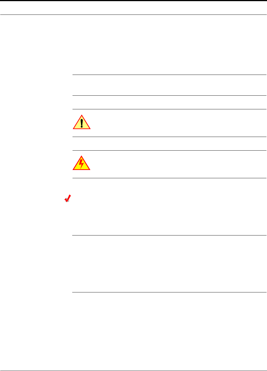
The InterReach Fusion system consists of three modular components:
• 19" rack-mountable Main Hub (connects to up to 4 Expansion Hubs)
• Converts RF signals to optical IF on the downlink; optical IF-to-RF on the
uplink
• Microprocessor controlled (for alarms, monitoring, and control)
• Auto-configurable bands
• Simplex interface to RF source
• Periodically polls all downstream RAUs for system status, and automatically
reports any fault or warning conditions
•19” rack mountable Expansion Hub (connects to up to 8 Remote Access Units)
• Optical signal conversion to electrical on the downlink; electrical to optical on
the uplink
• Microprocessor controlled (for alarms, monitoring, and control)
• Software configurable band (based on commands from the Main Hub)
• Supplies DC power to RAUs over CATV cable.
•Remote Access Unit (RAU)
• Converts IF signals to RF on the downlink; RF-to-IF on the uplink
• Microprocessor controlled (for alarms, monitoring, and control)
• Multi-band protocol independent, frequency specific units
The minimum configuration of a Fusion system is one Main Hub, one Expansion
Hub, and one RAU (1-1). The maximum configuration of a system is one Main Hub,
four Expansion Hubs, and 32 RAUs (1-4-32). Multiple systems can be combined to
provide larger configurations.
System OA&M Capabilities Overview
2-4 InterReach Fusion Installation, Operation, and Reference Manual
CONFIDENTIAL
D-620610-0-20 Rev A
Figure 2-1
Fusion System Hardware
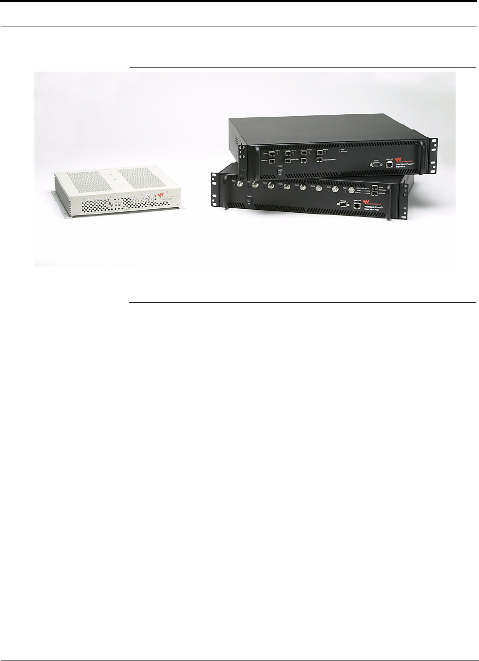
2.3 System OA&M Capabilities Overview
InterReach Fusion is microprocessor controlled and contains firmware to enable much of
the operations, administration, and maintenance (OA&M) functionality.
Complete alarming, down to the field replaceable unit (that is, Fusion Main Hub,
Expansion Hub, and Remote Access Unit) and the cabling infrastructure, is available.
All events occurring in a system, defined as a Fusion Main Hub and all of its associ-
ated Expansion Hubs and Remote Access Units, are automatically reported to the
Main Hub. The Main Hub monitors system status and communicates that status using
the following methods:
• Normally closed (NC) alarm contact closures can be tied to standard NC alarm
monitoring systems or directly to a base station for basic alarm monitoring.
• Connection Methods:
• The Main Hub’s front panel RJ-45 port connects directly to a PC (for local
Ethernet access).
• The Main Hub’s front panel RS-232 serial port connects directly to a modem
(for remote access).
• Remote access is also available with an optional 100BASE-T LAN switch con-
nections to the RJ-45 port.
Help Hot Line (U.S. only): 1-800-530-9960 2-5
D-620610-0-20 Rev A
CONFIDENTIAL
System OA&M Capabilities Overview
Figure 2-2
Three Methods for OA&M Communications
AdminBrowser OA&M software runs on the Fusion Main Hub microprocessor and
communicates to its downstream Expansion Hubs and associated RAUs. Using
AdminBrowser, you can perform the following from any standard web browser
(Internet Explorer) running on your PC/laptop system:
• Configure a newly installed system
• Change system parameters
• Perform an end-to-end system test
• Query system status
Refer to the AdminBrowser User Manual (D-620607-0-20 Rev A) for information
about installing and using AdminBrowser software.
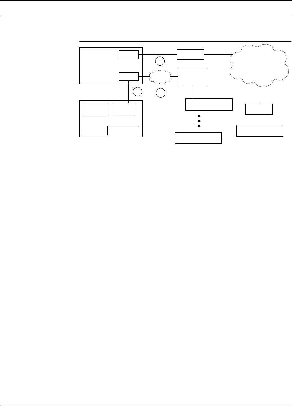
2.3.1 System Monitoring and Reporting
Each Fusion Main Hub in the system constantly monitors itself, its Expansion Hubs,
and their downstream RAUs for internal fault and warning conditions. The results of
this monitoring are stored in memory and compared against new results.
When a Main or Expansion Hub detects a change in status, it reports a fault or warn-
ing alarm. Faults are also indicated locally by red status LEDs. Both faults and warn-
ings are reported to AdminBrowser software and displayed on a PC/laptop connected
to the Main Hub’s RJ-45 port. Passive antennas connected to the RAUs are not moni-
tored automatically. Perform a System Test to retrieve status information about anten-
nas.
Using AdminBrowser, you can install a new system or new components, change sys-
tem parameters, and query system status. Figure 2-3 illustrates how the system
reports its status to AdminBrowser.
PSTN
RS-232
RS-232 Ethernet
PC/Laptop
running a
Modem
Fusion Main Hub
Modem
Fusion Main Hub
Ethernet
LAN
Switch
F-conn.
Fusion Main Hub
Fusion Main Hub
Standard Browser
Use AdminBrowser to configure
or monitor a local or a remote
Fusion system.
TCP/IP
1
2
3
R-J-45
t
Ethernet
Admin Browser
RS-232
Modem
System OA&M Capabilities Overview
2-6 InterReach Fusion Installation, Operation, and Reference Manual
CONFIDENTIAL
D-620610-0-20 Rev A
Figure 2-3
System Monitoring and Reporting
2.3.2 Using Alarm Contacts
You can connect the DB-9 female connector on the rear panel of the Fusion Main
Hub to a local base station or to a daisy-chained series of Fusion and/or MetroReach
Focus systems.
When you connect MetroReach Focus or a BTS to the Fusion, the Fusion Main Hub
outputs the alarms (alarm source) and MetroReach Focus or the BTS receives the
alarms (alarm sense). This is described in Section 7.7.1 on page 7-50.
Each RAU passes its status to
the Hub.
If a fault is detected, the
ALARM LED is red. If no fault
is detected, the LED is green.
The Expansion Hub queries
the status of each RAU and
compares it to the previously
stored status.
If a fault is detected, LEDs on
the front panel turn red.
Fusion Main
Hub
AdminBrowser
RAU
RAU
Use a standard
browser to communi-
cate with remotely or
locally installed Fusion
systems running
AdminBrowser.
If a fault or warning
condition is reported,
the AdminBrowser
graphical user inter-
face indicates the prob-
lem on your standard
PC browser.
web browser
Fusion
Expansion
Hub
PC/Laptop
running a
standard
The Main Hub queries
status of each Expan-
sion Hub and each
RAU and compares it
to previously stored
status.
If a fault is detected,
LEDs on the front panel
turn red.
AdminBrowser
Help Hot Line (U.S. only): 1-800-530-9960 2-7
D-620610-0-20 Rev A
CONFIDENTIAL
System Connectivity
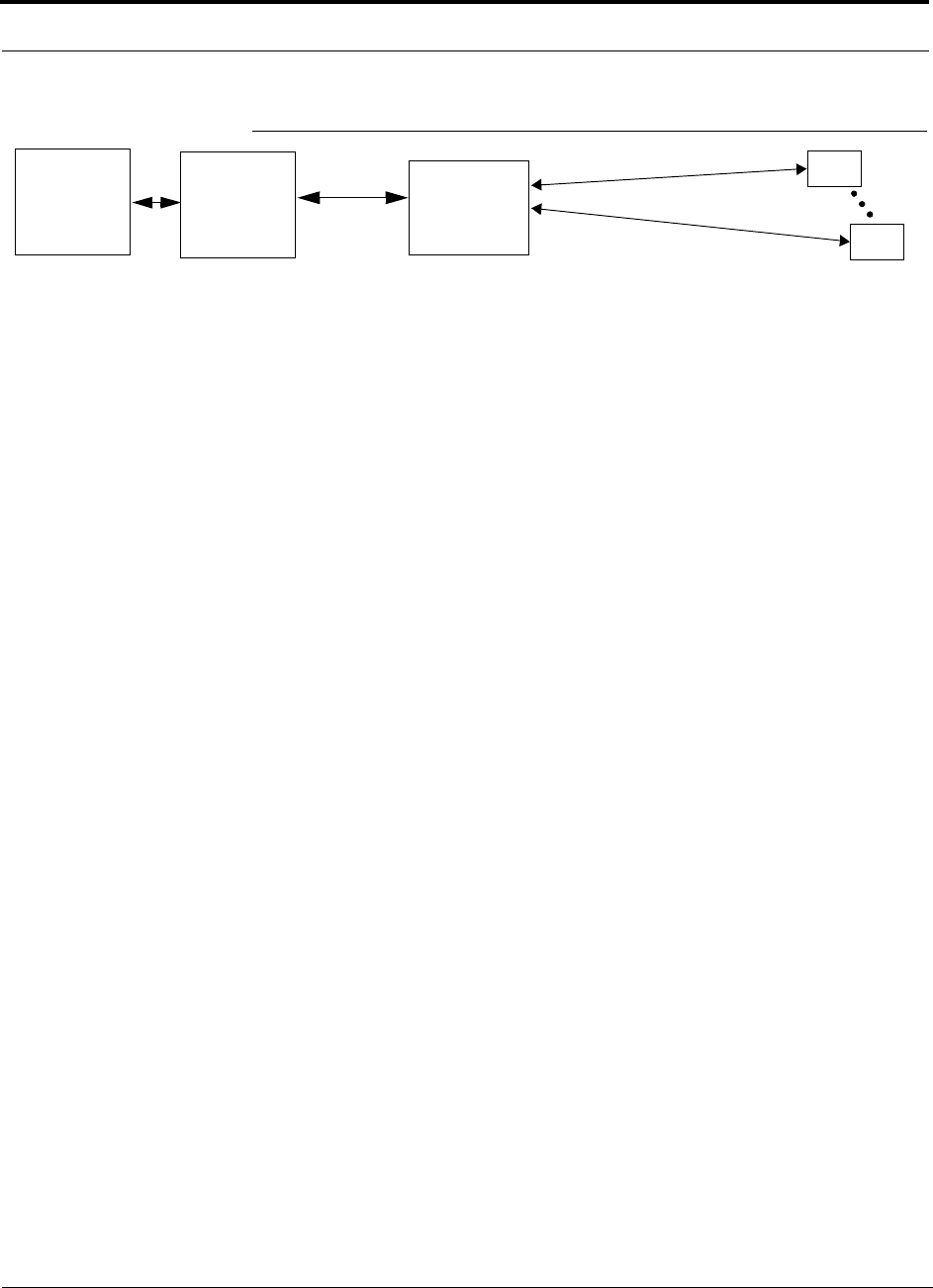
2.4 System Connectivity
The double star architecture of the Fusion system, illustrated in Figure 2-4, provides
excellent system scalability and reliability. The system requires only one pair of
fibers for eight antenna points. This makes any system expansion, such as adding an
extra antenna for additional coverage, potentially as easy as pulling an extra CATV
cable.
Figure 2-4
Fusion’s Double Star Architecture
Main Hub
RS-232
PORT 1 PORT 2 PORT 3 PORT 4
Expansion Hub
Expansion Hub
Fiber
Expansion Hub
Expansion Hub
CATVCATV (RG-59, 6, or 11) CATV
up to 8 RAUs per Expansion Hub
RAU RAU RAU
RJ-45
System Operation
2-8 InterReach Fusion Installation, Operation, and Reference Manual
CONFIDENTIAL
D-620610-0-20 Rev A
2.5 System Operation
Figure 2-5
Downlink (Base Station to Wireless Devices)
Figure 2-6
Uplink (Wireless Devices to Base Station)
Main Hub
RAU
The Main Hub receives downlink RF signals from
a base station using 50 Ohm coaxial cable.
The Main Hub converts the RF signals to IF, then
to optical signals and sends them to Expansion
Hubs (up to four) using optical fiber cable.
The Expansion Hub converts the optical sig-
nals to electrical signals and sends them to
RAUs (up to eight) using 75 Ohm CATV cable.
The RAU converts the IF signals
to RF and sends them to passive
antennas using 50 Ohm coaxial
cable.
Expansion Hub
Main Hub
RAU
The Main Hub sends
uplink RF signals to a
base station using
50 Ohm coaxial cable.
The Main Hub receives
the optical signals from
the Expansion Hubs (up
to four) using optical
fiber cable and con-
verts them to RF sig-
nals.
The Expansion Hub
receives the IF signals
from the RAUs (up to
eight) using CATV cable
and converts them to
optical signals.
The RAU receives uplink RF
signals from the passive
antenna using 50 Ohm coaxial
cable and converts them to IF
signals.
Expansion Hub

Help Hot Line (U.S. only): 1-800-530-9960 2-9
D-620610-0-20 Rev A
CONFIDENTIAL
System Specifications
2.6 System Specifications
Table 2-1
Physical Specifications
Parameter Main Hub Expansion Hub Remote Access Unit
IF/RF Connectors 6-type “N”, female (50 Ohm),
1 Downlink/Uplink pair per band
8-type “F”, female (CATV
75 Ohm)
One F, female (CATV -75
Ohm)
One N, female (coaxial - 50
Ohm)
External Alarm Connector
(contact source)
One, 9-pin D-sub, female One, 9-pin D-sub, female —
ADMIN/LAN Interface
Connectors
One RJ-45, female
One 9-pin D-sub, male for
optional modem
One RJ-45, female
One 9-pin D-sub, male
—
Fiber Connectors*
*It is critical to system performance that only SC/APC fiber connectors are used throughout the fiber network, including fiber distribution pan-
els.
4 pair, SC/APC One pair, SC/APC —
LED Alarm and Status
Indicators
Unit Status (One pair):
• Power
• Main Hub Status
Downstream Unit Status
(One per fiber port):
• Expansion Hub/RAU
Unit Status (One pair):
• Power
• Expansion Hub Status
Fiber Link Status (One
pair):
• DL Status
• UL Status
Port Status:
• One per F connector port
• Link/RAU
Unit Status (One pair):
• Link
• Alarm
Power (Volts) Rating: 100–240V AC, 1A,
50–60 Hz
Operating Range: 90–132V
AC/170-250V AC auto-ranging
Rating: 100–240V AC,
6A, 50–60 Hz
Operating Range:
90–132V AC/170-250V
AC auto-ranging
—
Power Consumption (W) 30 4 RAUs: 305 typical
8 RAUs: 530 typical
—
Enclosure Dimensions†
(height
×
width
×
depth)
†Excluding angle-brackets for 19'' rack mounting of hub.
Note: The Fusion Main Hub’s typical power consumption assumes that the CATV RG-59 cable length is no more than 150 meters, the RG-6
cable length is no more than 170 meters, and RG-11 cable length is no more than 275 meters using CommScope 2065V, 2279V, and 2293K
cables.
89 mm × 438 mm × 381 mm
(3.5 in. × 17.25 in. × 15 in.) (2U)
89 mm × 438 mm × 381
mm
(3.5 in. × 17.25 in. × 15
in.) (2U)
54 mm x 286 mm x 281 mm
(2.13 in. × 11.25 in. × 11.13
in.)
Weight < 5.5 kg (< 12 lbs.) < 6.6 kg (< 14.5 lbs.) < 2.1 kg (< 4.6 lbs.)

System Specifications
2-10 InterReach Fusion Installation, Operation, and Reference Manual
CONFIDENTIAL
D-620610-0-20 Rev A
Table 2-2
Wavelength and Laser Power Specifications
Measured Output Power
Wavelength Main Hub Expansion Hub
1310 nm +20 nm 890 uW 3.8 mW
Table 2-3
Environmental Specifications
Parameter Main Hub and Expansion Hub RAU
Operating Temperature 0° to +45°C (+32° to +113°F) –25° to +45°C (–13°
to +113°F)
Non-operating Tempera-
ture
–20° to +85°C (–4° to +185°F) –25° to +85°C (–13°
to +185°F)
Operating Humidity;
non-condensing
5% to 95% 5% to 95%
Table 2-4
Frequency Bands Covered by Fusion RAUs
Fusion
RAU Part Number
Fusion
Band
RF Passband
Downlink
(MHz)
Uplink
(MHz)
MAIN
HUB/
RAU
Band
RAU
Band-
width
850/1900 FSN-8519-1 850 869–894 824–849 1 25 MHz
1900 1930–1990 1850–1910 2 60 MHz
900//1800 FSN-9018-1 900 925–960 880–915 1 35 MHz
1800 1805–1880 1710–1785 2 75 MHz
900/2100 FSN-9021-1 900 925–960 830–715 1 35 MHz
2100 2110–2170 1920–1980 2 60 MHz
800/900/
1900
FSN-809019-1 800
SMR
851-869 806-824 1 (sub
band
1A)
18 MHz
900
SMR
935-941 896-902 3 (sub
band
1B)
6 MHz
1900
(A-G)
1930-1995 1850-1915 2 65 MHz

Help Hot Line (U.S. only): 1-800-530-9960 2-11
D-620610-0-20 Rev A
CONFIDENTIAL
System Specifications
2.6.1 RF End-to-End Performance
The following tables list the RF end-to-end performance of each protocol.
NOTE: The system gain is adjustable in 1 dB steps from 0 to 15 dB, and the
gain of each RAU can be attenuated up to 10 dB in 1dB steps.
850/1900 RAU
Table 2-5
850 MHz RF End-to-End Performance
Parameter
Typical
Downlink Uplink
Average gain with 75 m RG-59 at 25°C (77°F) (dB) 15 15
Ripple with 150 m RG-59 (dB) 2.5 3
Output IP3 (dBm) 38
Input IP3 (dBm) –5
Output 1 dB Compression Point (dBm) 26
Noise Figure 1 MH, 1 EH, 8 RAUs (dB) 16
Noise Figure 1 MH, 4 EH, 32 RAUs (dB) 22
Table 2-6
1900 MHz RF End-to-End Performance
Parameter
Typical
Downlink Uplink
Average gain with 75 m RG-59 at 25°C (77°F) (dB) 15 15
Ripple with 150 m RG-59 (dB) 3.5 4
Output IP3 (dBm) 38
Input IP3 (dBm) -5
Output 1 dB Compression Point (dBm) 26
Noise Figure 1 MH, 1 EH, 8 RAUs (dB) 16
Noise Figure 1 MH, 4 EH, 32 RAUs (dB) 22

System Specifications
2-12 InterReach Fusion Installation, Operation, and Reference Manual
CONFIDENTIAL
D-620610-0-20 Rev A
900/1800 RAU
Table 2-7
900 MHz RF End-to-End Performance
Typical
Parameter Downlink Uplink
Average Downlink gain with 75 m RG-59 at 25°C (77°F) (dB) 15 15
Ripple with 75 m RG-59 (dB) 3 4
Output IP3 (dBm) 38
Input IP3 (dBm) –5
Output 1 dB Compression Point (dBm) 26
Noise Figure 1 MH, 1 EH, 8 RAUs (dB) 16
Noise Figure 1 MH, 4 EH, 32 RAUs (dB) 22
Table 2-8
1800 MHz RF End-to-End Performance
Typical
Parameter Downlink Uplink
Average gain with 75 m RG-59 at 25°C (77°F) (dB) 15 15
Downlink ripple with 75 m Cat-5/5E/6 (dB) 2
Uplink ripple with 75 m RG-59 (dB) 2
Uplink gain roll off with 75 m RG-59 (dB)*
*Outside the center 60 MHz
2
Output IP3 (dBm) 38
Input IP3 (dBm) –5
Output 1 dB Compression Point (dBm) 26
Noise Figure 1 MH, 1 EH, 8 RAUs (dB) 16
Noise Figure 1 MH, 4 EH, 32 RAUs (dB) 22

Help Hot Line (U.S. only): 1-800-530-9960 2-13
D-620610-0-20 Rev A
CONFIDENTIAL
System Specifications
900/2100 RAU
800/900/1900 RAU
Table 2-9
900 MHz RF End-to-End Performance
Typical
Parameter Downlink Uplink
Average Downlink gain with 75 m RG-59 at 25°C (77°F) (dB) 15 15
Ripple with 75 m RG-59 (dB) 3 4
Output IP3 (dBm) 38
Input IP3 (dBm) –5
Output 1 dB Compression Point (dBm) 26
Noise Figure 1 MH, 1 EH, 8 RAUs (dB) 16
Noise Figure 1 MH, 4 EH, 32 RAUs (dB) 22
Table 2-10
2100 MHz RF End-to-End Performance
Parameter
Typical
Downlink Uplink
Average gain w/ 75 meters RG-59 @ 25
°
C (dB) 15 15
Ripple with 75 m RG-59 (dB) 2.5 4
Spurious Output Levels (dBm) <–30
UMTS TDD Band Spurious Output Level
1900–1920 MHz, 2010–2025 MHz (dBm/MHz)
<–52
Output IP3 (dBm) 37
Input IP3 (dBm) –5
Output 1 dB Compression Point (dBm) 26
Noise Figure 1 MH, 1 EH, 8 RAUs (dB) 16
Noise Figure 1 MH, 4 EH, 32 RAUs (dB) 22
Table 2-11
800 MHz (SMR) RF End-to-End Performance
Typical
Parameter Downlink Uplink
Average Downlink gain with 150 m CATV at 25°C (77°F) (dB) 15 15
Ripple with 150 m CATV (dB) 2.5 3
Output IP3 (dBm) 38
Input IP3 (dBm) –5
Output 1 dB Compression Point (dBm) 25
Noise Figure 1 MH-1 EH-8 RAUs (dB) 17
Noise Figure 1 MH-4 EH-32 RAUs (dB) 23

System Specifications
2-14 InterReach Fusion Installation, Operation, and Reference Manual
CONFIDENTIAL
D-620610-0-20 Rev A
Table 2-12
900 MHz (SMR) RF End-to-End Performance
Typical
Parameter Downlink Uplink
Average Downlink gain with 150 m CATV at 25°C (77°F) (dB) 15 15
Ripple with 150 m CATV (dB) 2.5 3
Output IP3 (dBm) 35
Input IP3 (dBm) –5
Output 1 dB Compression Point (dBm) 23
Noise Figure 1 MH-1 EH-8 RAUs (dB) 17
Noise Figure 1 MH-4 EH-32 RAUs (dB) 23
Table 2-13
1900 MHz RF End-to-End Performance
Typical
Parameter Downlink Uplink
Average Downlink gain with 150 m CATV at 25°C (77°F) (dB) 15 15
Ripple with 150 m CATV (dB) 3.5 4
Output IP3 (dBm) 38
Input IP3 (dBm) –5
Output 1 dB Compression Point (dBm) 26
Noise Figure 1 MH-1 EH-8 RAUs (dB) 17
Noise Figure 1 MH-4 EH-32 RAUs (dB) 23

InterReach Fusion Installation, Operation, and Reference Manual 3-1
D-620610-0-20 Rev A
CONFIDENTIAL
SECTION 3
Fusion Main Hub
This section contains the following subsections:
• Section 3.1 Fusion Main Hub Overview . . . . . . . . . . . . . . . . . . . . . . . . . . . . . 3-1
• Section 3.2 Fusion Main Hub Front Panel . . . . . . . . . . . . . . . . . . . . . . . . . . . 3-4
• Section 3.3 Fusion Main Hub Rear Panel . . . . . . . . . . . . . . . . . . . . . . . . . . . . 3-8
• Section 3.4 Main Hub Specifications . . . . . . . . . . . . . . . . . . . . . . . . . . . . . . 3-10
• Section 3.5 Faults, Warnings, and Status Messages . . . . . . . . . . . . . . . . . . . 3-11
3.1 Fusion Main Hub Overview
The Fusion Main Hub (shown in Figure 3-1) distributes up to three individual (Band
1, 2, or 3) downlink RF signals from a base station, repeater, or MetroReach Focus
system to up to four Expansion Hubs, which in turn distribute the signals to up to 32
Remote Access Units. The Main Hub also combines uplink signals from the associ-
ated Expansion Hubs.
Fusion is a multi-band system. One RF source (Band 1 or RF1) goes to the 35 MHz
band and the other RF source (Band 2 or RF2) goes to the 75 MHz band. Band 3 (or
RF3) goes to a 6 MHz sub-band of the 35 MHz band and is functional only with the
800/900/1900 RAU. The system installs in a 19" equipment rack and is usually
co-located with the RF source in a telecommunications closet.
Fusion Main Hub Overview
3-2 InterReach Fusion Installation, Operation, and Reference Manual
CONFIDENTIAL
D-620610-0-20 Rev A
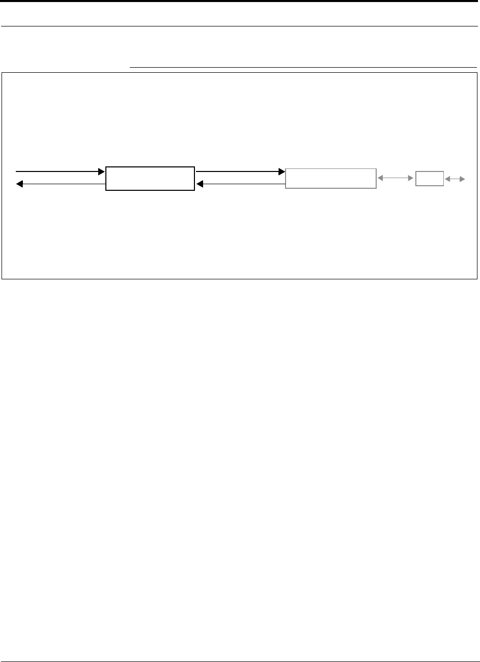
Figure 3-1
Main Hub in a Fusion System
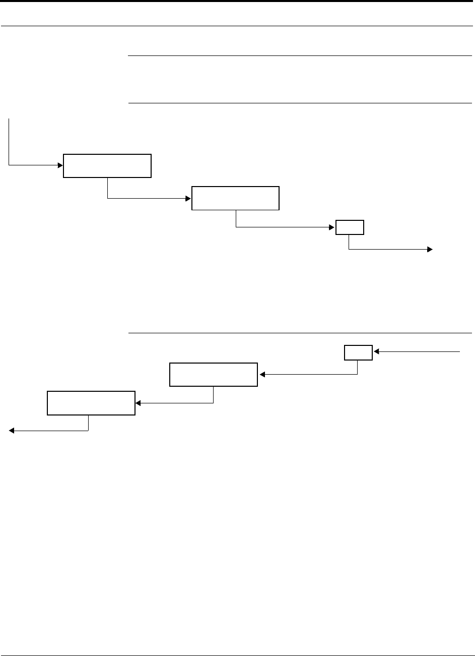
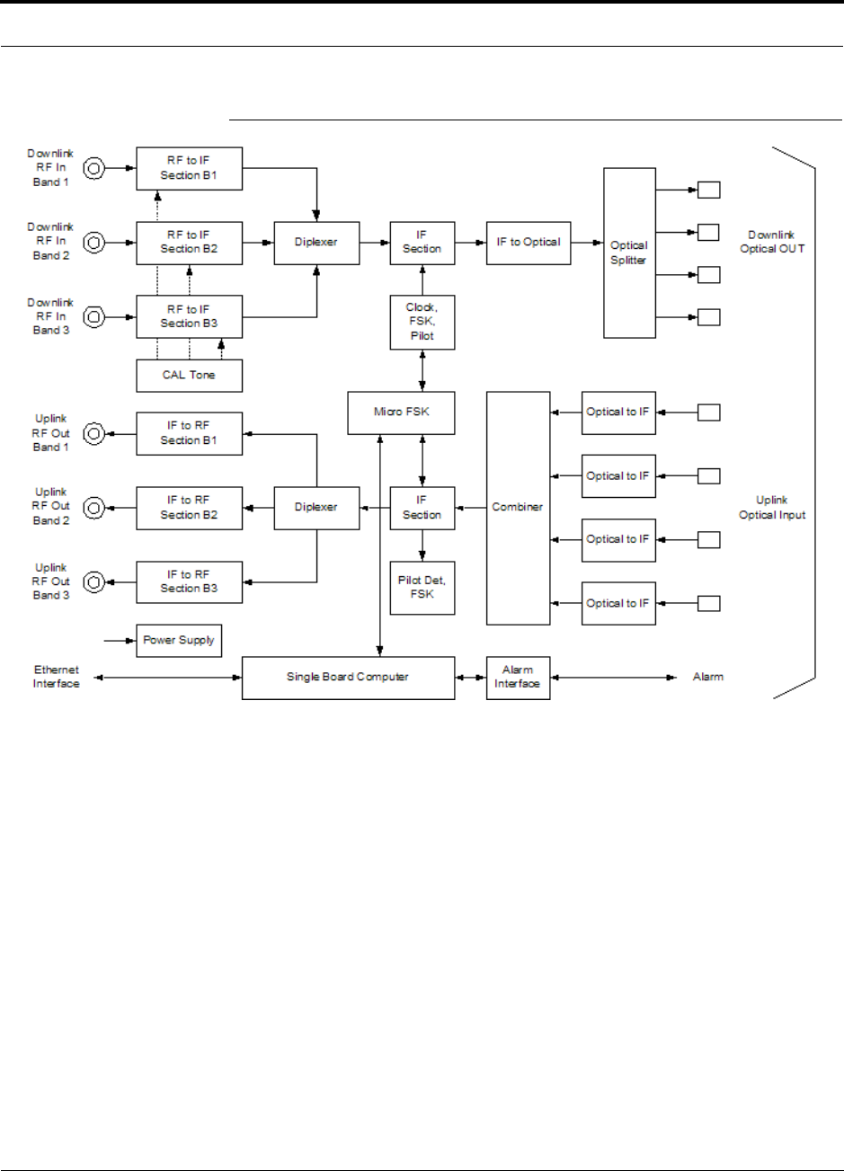
Figure 3-2 shows a detailed view of the major RF and optical functional blocks of the
Main Hub.
Fusion Main Hub
Fusion Expansion Hub RAU
Downlink Path: The Main Hub receives up to 3 individual (Band1, 2, or 3) downlink RF signals from a base station, repeater,
or MetroReach Focus system using 50 Ohm coaxial cable. It converts the signals to IF then to optical and sends them to up to
four Expansion Hubs using fiber optic cable.
The Main Hub also sends OA&M communication to the Expansion Hubs using the fiber optic cable. The Expansion Hubs, in
turn, communicate the OA&M information to the RAUs using CATV cable.
Uplink Path: The Main Hub receives uplink optical signals from up to four Expansion Hubs using fiber optic cables. It con-
verts the signals to IF then to RF and sends them to the respective Band1, 2, or 3 base station, repeater, or MetroReach
Focus system using 50 Ohm coaxial cable.
The Main Hub also receives status information from the Expansion Hubs and all RAUs using the fiber optic cable.
Downlink to Main Hub
Uplink from Main Hub
Downlink from Main Hub
Uplink to Main Hub
RF1, 2, and 3
RF1, 2, and 3
Help Hot Line (U.S. only): 1-800-530-9960 3-3
D-620610-0-20 Rev A
CONFIDENTIAL
Fusion Main Hub Overview
Figure 3-2
Main Hub Block Diagram
Fusion Main Hub Front Panel
3-4 InterReach Fusion Installation, Operation, and Reference Manual
CONFIDENTIAL
D-620610-0-20 Rev A
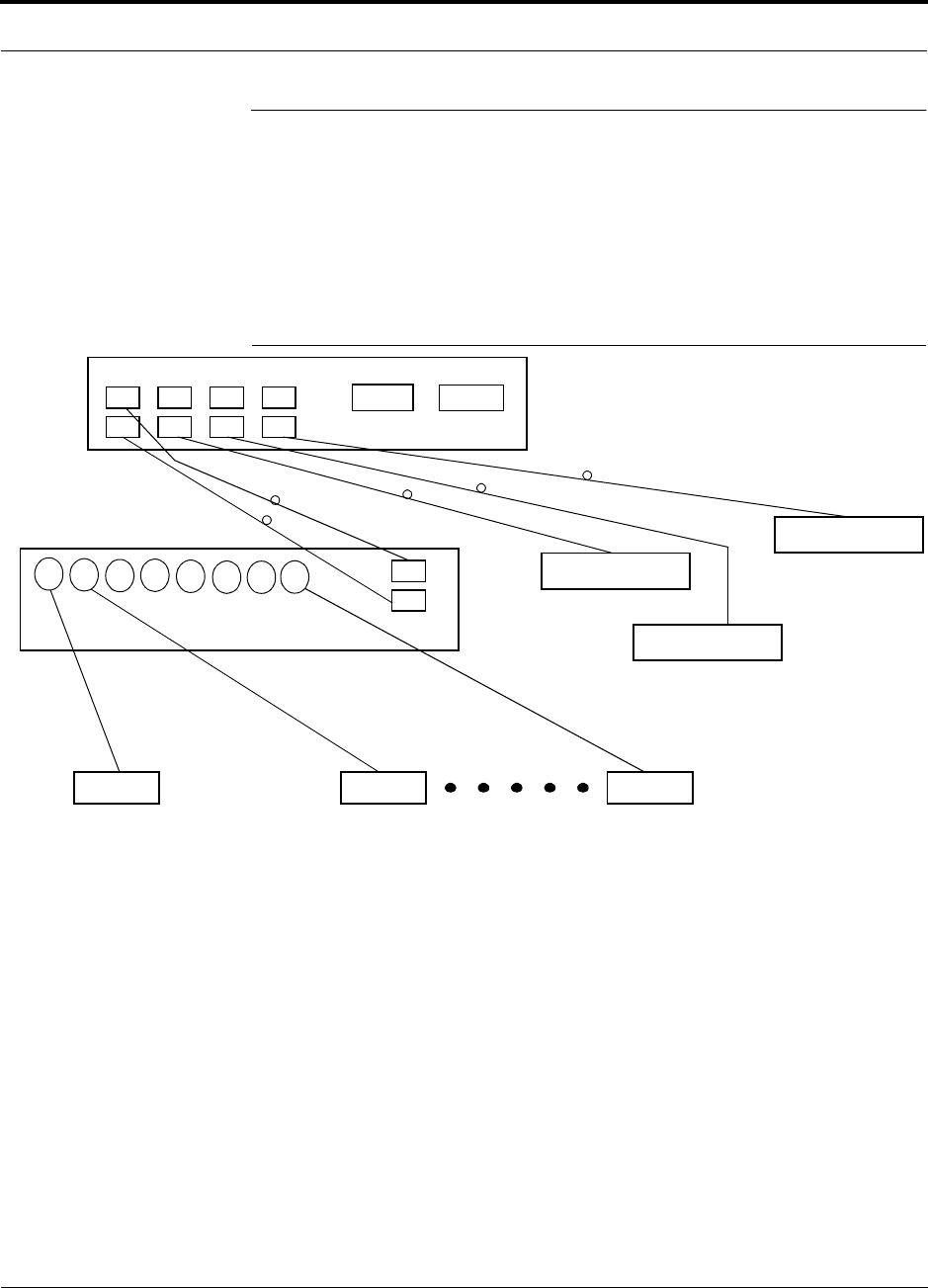
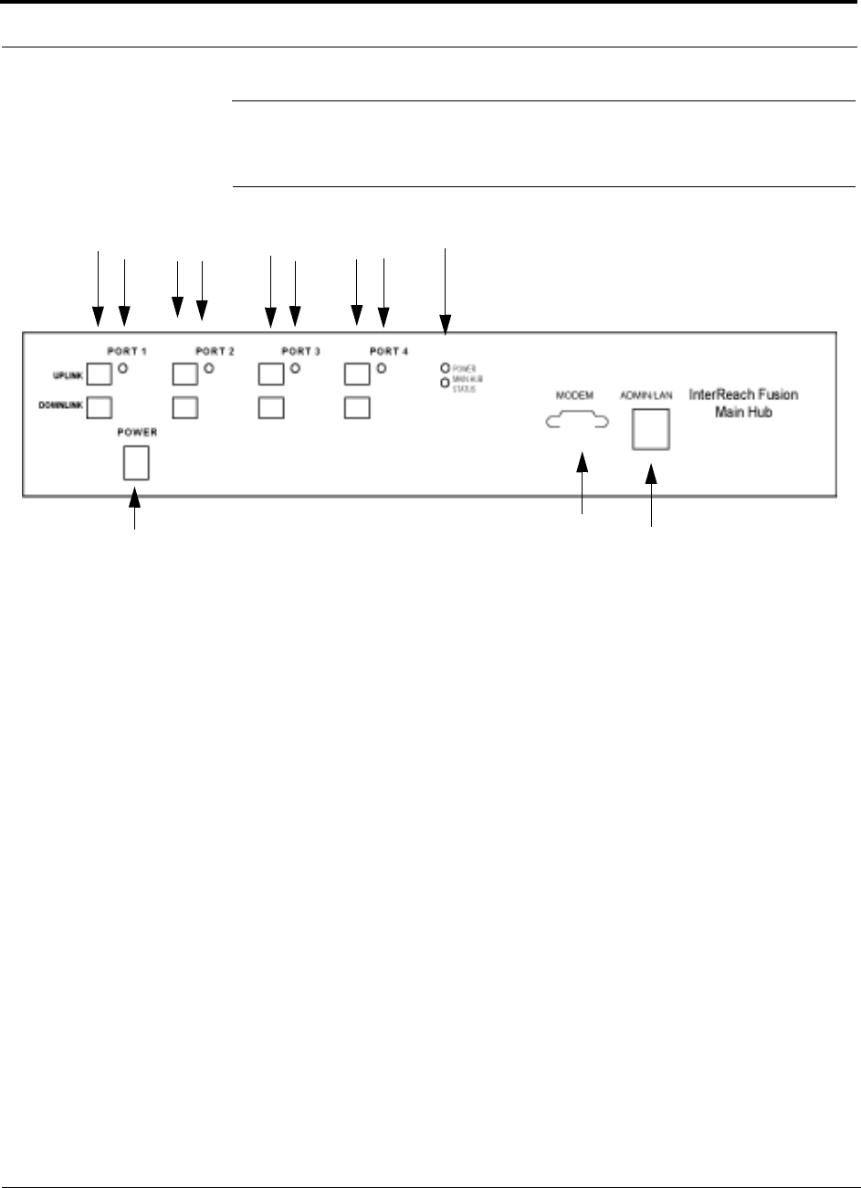
3.2 Fusion Main Hub Front Panel
Figure 3-3
Fusion Main Hub Front Panel
1.
Four fiber optic ports (labeled
PORT 1
,
PORT 2
,
PORT 3
,
PORT 4
)
• One standard female SC/APC connector per port for MMF/SMF input (labeled
UPLINK
)
• One standard female SC/APC connector per port for MMF/SMF output
(labeled
DOWNLINK
)
2.
Four sets of fiber port LEDs (one set per port)
• One LED per port for port link status and downstream unit status
3.
One set of unit status LEDs
• One LED for unit power status (labeled
POWER
)
• One LED for unit status (labeled
MAIN HUB STATUS
)
4.
One 9-pin D-sub male connector for system remote dial-up communication and
diagnostics using a modem (labeled
MODEM
)
5.
One RJ-45 female connector for system communication and diagnostics using a
PC/laptop with direct connect or using a LAN switch (labeled
ADMIN/LAN
)
6.
Power switch
12
3
6
45
121212
Help Hot Line (U.S. only): 1-800-530-9960 3-5
D-620610-0-20 Rev A
CONFIDENTIAL
Fusion Main Hub Front Panel
3.2.1 Optical Fiber Uplink/Downlink Ports
The optical fiber uplink/downlink ports transmit and receive optical signals between
the Main Hub and up to four Expansion Hubs using industry-standard SMF or MMF
cable. There are four fiber ports on the front panel of the Main Hub; one port per
Expansion Hub. Each fiber port has two female SC/APC connectors:
• Optical Fiber Uplink Connector
This connector (labeled
UPLINK
) is used to receive the uplink optical signals from
an Expansion Hub.
• Optical Fiber Downlink Connector
This connector (labeled
DOWNLINK
) is used to transmit the downlink optical sig-
nals to an Expansion Hub.
CAUTION: To avoid damaging the Main Hub’s fiber connector ports,
use only SC/APC fiber cable connectors when using either single-mode
or multi-mode fiber. Additionally, it is critical to system performance
that only SC/APC fiber connectors are used throughout the fiber network, includ-
ing fiber distribution panels.
3.2.2 Communications RS-232 Serial Connector
Remote Monitoring
Use a standard serial cable to connect a modem to the 9-pin D-sub male serial con-
nector for remote monitoring or configuring. The cable typically has a DB-9 female
and a DB-25 male connector. Refer to Appendix A.6 on page A-11 for the cable
pinout diagram.
Remote monitoring is also available by connecting the RJ-45 (ADMIN/LAN) port to
a LAN switch for remote Ethernet LAN access or direct dial-up router access.
Local Monitoring
Use a crossover Ethernet cable (PN-4069-ADB) to connect a laptop or PC to the
RJ-45 female connector for local monitoring or configuring using the AdminBrowser
resident software. The cable typically has a RJ-45 male connector on both ends. Refer
to Appendix A.5 on page A-10 for the cable pinout.
3.2.3 Main Hub LED Indicators
The unit’s front panel LEDs indicate faults and commanded or fault lockouts. The
LEDs do not indicate warnings or whether the system test has been performed. Use the
LEDs to provide basic information only, or as a backup when you are not using Admin-
Browser.
Fusion Main Hub Front Panel
3-6 InterReach Fusion Installation, Operation, and Reference Manual
CONFIDENTIAL
D-620610-0-20 Rev A
Upon power up, the Main Hub goes through a 20-second test to check the LED
lamps. During this time, the LEDs blink through the states shown in Table 3-1, letting
you visually verify that the LED lamps and the firmware are functioning properly.
Upon completion of initialization, the LEDs stay in one of the first two states shown
in Table 3-1.
The Main Hub automatically sends the program bands command to all connected
RAUs. A mismatched band causes a fault message to be displayed in AdminBrowser
and places the RAU in a disabled condition.
NOTE: Refer to Section 9.3.2 for troubleshooting using the LEDs.
NOTE: AdminBrowser should be used for troubleshooting the system.
Only use LEDs for backup or confirmation. However, if there are communi-
cation problems within the system, the LEDs may provide additional infor-
mation that is not available using AdminBrowser.
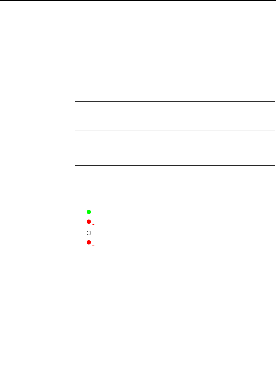
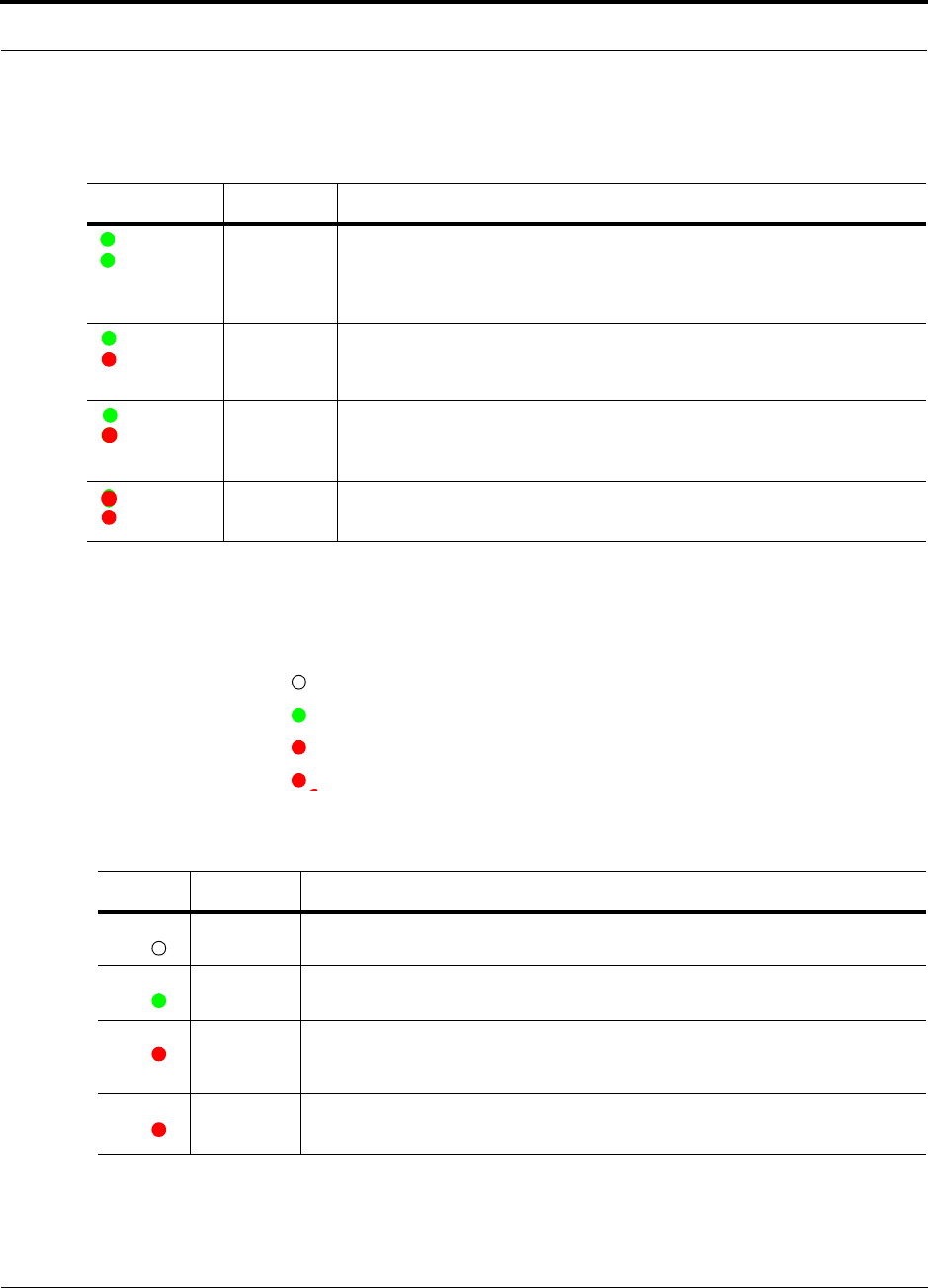
Unit Status LEDs
The Main Hub has one pair of status LEDs, labeled
POWER
and
STATUS
, which can
be in one of the states shown in Table 3-1. These LEDs can be:
steady green
steady red
off - no color (valid only during 90 second power cycle)
flashing red (60 ppm)
There is no off state when the unit’s power is on.
Help Hot Line (U.S. only): 1-800-530-9960 3-7
D-620610-0-20 Rev A
CONFIDENTIAL
Fusion Main Hub Front Panel
Fiber Port LEDs
The Main Hub has one fiber port LED for each of the four fiber ports. The LED can
be in one of the states shown in Table 3-2. This LED can be:
off
steady green
steady red
flashing red (60 ppm)
Table 3-1
Fusion Hub Status LED States
LED State Indicates
Green
Green
• The Main Hub is connected to power and all power supplies are operating.
• The Main Hub is not reporting a fault; however, the system test may need to
be performed or a warning condition may exist. Use AdminBrowser to deter-
mine this.
Green
Red
• The Main Hub is connected to power and all power supplies are operating.
Use AdminBrowser to power status.
• The Main Hub is reporting a fault or lockout condition.
Green
Red
(60-ppm)
• The Main Hub is connected to power and all power supplies are operating.
• The Main Hub DL input signal level is too high.
Red
Red
• One or more power supplies are out-of-specification.
Table 3-2
Fusion Hub Port LED States
LED State Indicates
Off • The Expansion Hub is not connected.
Green
• The Expansion Hub is connected.
• There are no faults from the Expansion Hub or any connected RAU.
Red
(60 PPM)
• There was a loss of communications with the Expansion Hub.
Red
(Steady)
• The Expansion Hub is disconnected.
• The Expansion Hub or any connected RAU reported a fault or lockout condition.
POWER
STATUS
POWER
STATUS
POWER
STATUS
POWER
STATUS
PORT
PORT
PORT
PORT
Fusion Main Hub Rear Panel
3-8 InterReach Fusion Installation, Operation, and Reference Manual
CONFIDENTIAL
D-620610-0-20 Rev A
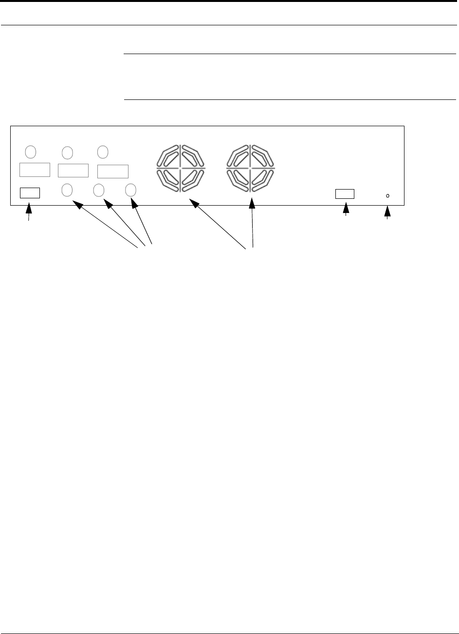
3.3 Fusion Main Hub Rear Panel
Figure 3-4
Fusion Main Hub Rear Panel
1.
AC power cord connector
2.
Two air exhaust vents
3.
Three N-type, female connectors for each band (Band 1, Band 2, and Band 3):
• Uplink (labeled
UL1, UL2,
and
UL3
)
• Downlink (labeled
DL1, DL2,
and
DL3
)
4.
One 9-pin D-sub female connector for contact alarm monitoring (labeled
ALARMS
)
5.
Ground lug for connecting unit to frame ground (labeled
GROUND
)
3.3.1 Fusion Main Hub Rear Panel Connectors
3.3.1.1 9-pin D-sub Connector
The 9-pin D-sub connector (labeled
ALARMS
) provides a contact alarm for fault and
warning system alarm monitoring.
Table lists the function of each pin on the 9-pin D-sub connector.
1
2
3
Band 1 Band 2 Band 3
UL1 UL2 UL3
DL1 DL2 DL3
45
AC Power
Alarms

Help Hot Line (U.S. only): 1-800-530-9960 3-9
D-620610-0-20 Rev A
CONFIDENTIAL
Fusion Main Hub Rear Panel
This interface can both generate two source contact alarms (Fault and Warning) and
sense 3 single external alarm contacts (Alarm Sense Input 1 through 3).
3.3.1.2 N-type Female Connectors
There are two 50 Ohm N-type connector pairs for each of the 3 bands on the rear
panel of the Hub:
• The
DOWNLINK
connector receives downlink RF signals from a repeater, local
base station, or MetroReach Focus system.
• The
UPLINK
connector transmits uplink RF signals to a repeater, local base sta-
tion, or MetroReach Focus system.
CAUTION:The
UPLINK
and
DOWNLINK
ports cannot handle a DC power
feed from the local base station. If DC power is present, a DC block must be
used or the Fusion hub may be damaged.
Table 3-3
9-pin D-sub Pin Connector Functions
Pin Function
1 Alarm Sense Input (DC Ground)
2 Alarm Sense Input 3
3 Alarm Sense Input 2
4 Warning Source Contact (positive connection)
5 Warning Source Contact (negative connection)
6 DC Ground (common)
7 Fault Source Contact (positive connection)
8 Alarm Sense Input 1
9 Fault Source Contact (negative connection)

Main Hub Specifications
3-10 InterReach Fusion Installation, Operation, and Reference Manual
CONFIDENTIAL
D-620610-0-20 Rev A
3.4 Main Hub Specifications
Table 3-4
Main Hub Specifications
Specification Description
Enclosure Dimensions (H
×
W
×
D)
a
:
a. Excluding angle brackets for the 19” rack mounting of the Hub.
89 mm x 438 mm x 381 mm (3.5 in. x 17.25 in. x 15 in.) 2U
Weight <5.5 kg (<12 lb)
Operating Temperature 0° to +45°C (+32° to +113°F)
Non-operating Temperature –20° to +85°C (–4° to +185°F)
Operating Humidity, non-condensing 5% to 95%
External Alarm Connector
(contact closure)
1 9-pin D-sub, female
Maximum: 40 mA @ 40V DC
Typical: 4 mA @ 12V DC
ADMIN/LAN Interface Connector 1 RJ-45, female
1 9-pin D-sub, male for optional modem
Fiber Connectors 4 Pair, SC/APC
b
b. It is critical to system performance that only SC/APC fiber connectors are used throughout the fiber network, including
fiber distribution panels.
RF Connectors 6 N, female (50 Ohm), 1 Downlink/Uplink pair per band
LED Fault and Status Indicators Unit Status (1 pair):
• Power
• Main Hub Status
Downstream Unit/Link Status (1 per fiber port):
• Link/E-Hub/RAU
AC Power Rating 115/230V AC, 2/1A, 50-60 Hz
Operating Range: 90-132V AC/170-250V AC auto-ranging
Power Consumption (W) 30
MTBF 117,972 hours

Help Hot Line (U.S. only): 1-800-530-9960 3-11
D-620610-0-20 Rev A
CONFIDENTIAL
Faults, Warnings, and Status Messages
3.5 Faults, Warnings, and Status Messages
3.5.1 Description
The Fusion Main Hub monitors and reports changes or events in system performance
to:
• Ensure that fiber receivers, amplifiers and IF/RF paths are functioning properly.
• Ensure that Expansion Hubs and Remote Access Units are connected and function-
ing properly.
An event is classified as fault, warning, or status message.
• Faults are service impacting.
• Warnings indicate a possible service impact.
• Status and informational messages are generally not service impacting.
The Fusion Main Hub periodically queries attached Expansion Hub and Remote
Access Units for their status. Both faults and warnings are reported to a connected
PC/laptop running a standard browser communicating with the AdminBrowser soft-
ware. Only faults are indicated by the faceplate LEDs.
For more information regarding the events, refer to:
• Appendix C for Main Hub faults.
• Appendix C for Main Hub warnings.
• Appendix C for Main Hub status messages.
• Section 9 for troubleshooting Main Hub LEDs.
Faults, Warnings, and Status Messages
3-12 InterReach Fusion Installation, Operation, and Reference Manual
CONFIDENTIAL
D-620610-0-20 Rev A
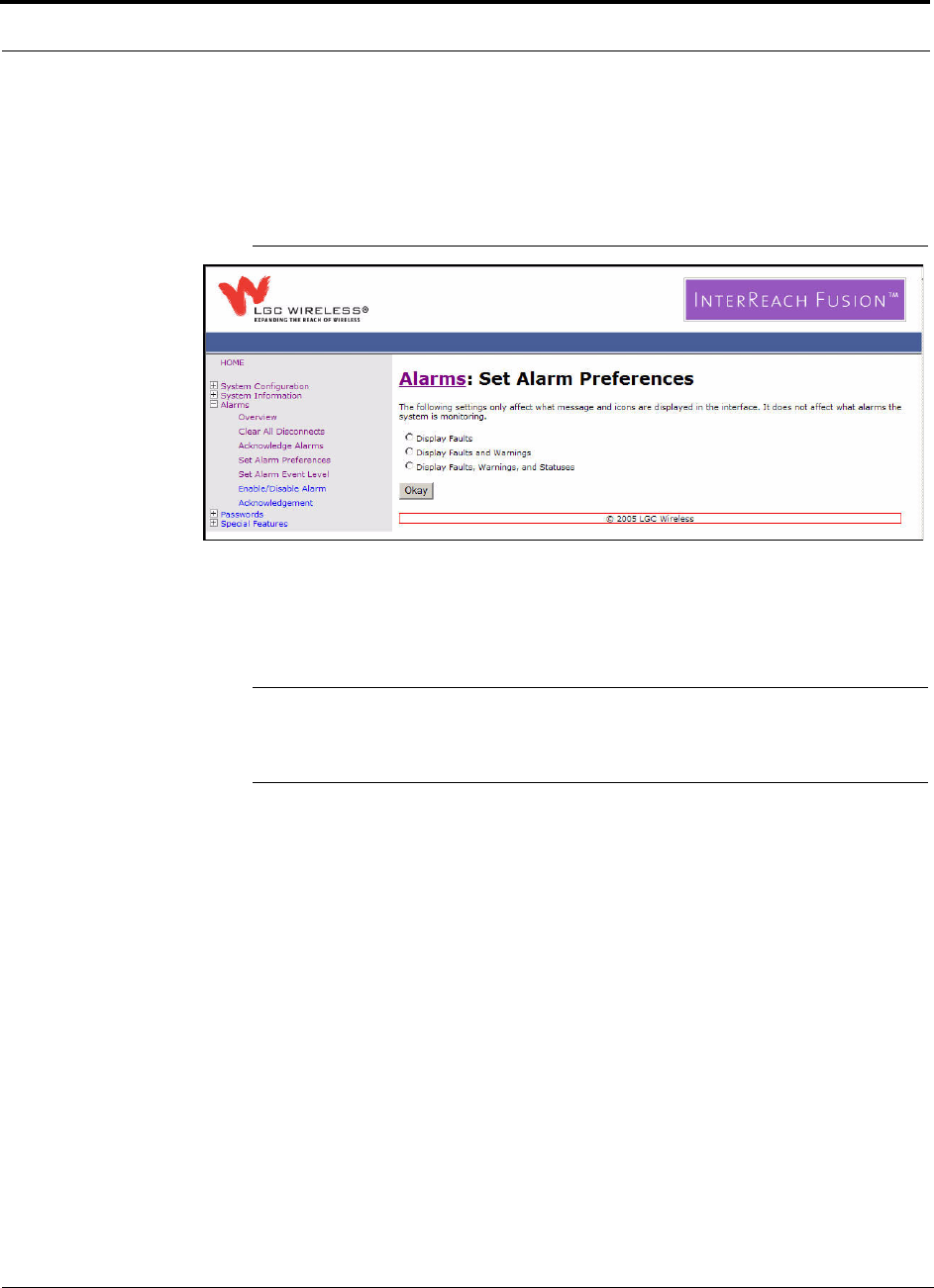
3.5.2 View Preference
AdminBrowser 1.0 or higher enables you to select (using the screen shown in
Figure 3-5) the type of events to be displayed.
Figure 3-5
Preferences Check Boxes
To modify the setting, using AdminBrowser, select Alarms Set Alarm Preference
and select the desired choice. After you click
OK
, AdminBrowser refreshes and
updates the tree view according to the new setting.
NOTE: The setting is strictly visual and only in AdminBrowser. There is no
affect on the hardware itself. By default, the event filtering is set to “Enable
viewing of Faults only”.
The only exception to when the event filtering is ignored is during the Install/Config-
ure command. All events are displayed regardless of the event filtering setting. This
ensures a smooth installation.
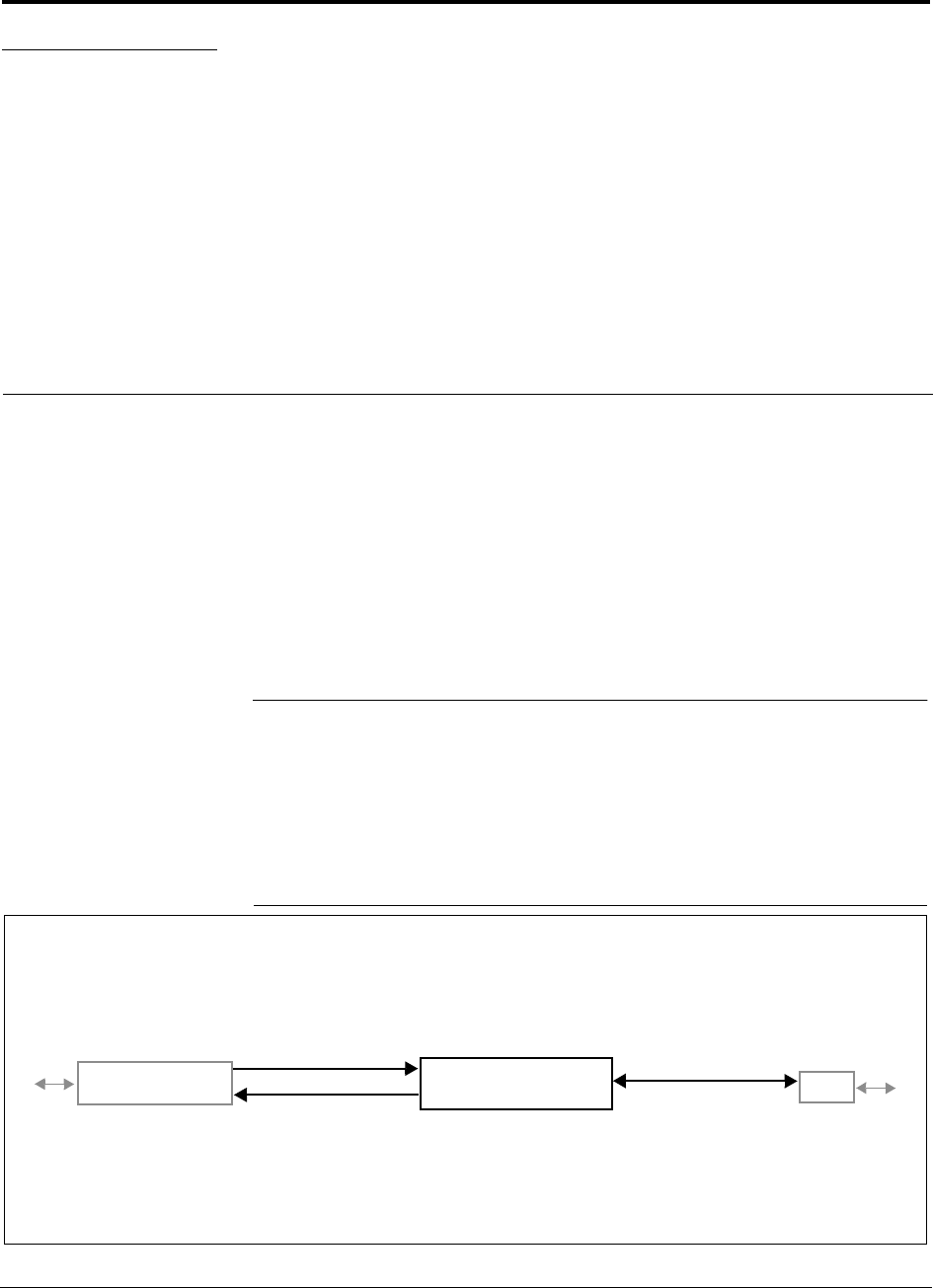
InterReach Fusion Installation, Operation, and Reference Manual 4-1
D-620610-0-20 Rev A
CONFIDENTIAL
SECTION 4
Fusion Expansion Hub
This section contains the following subsections:
• Section 4.1 Expansion Hub Overview . . . . . . . . . . . . . . . . . . . . . . . . . . . . . 4-1
• Section 4.2 Expansion Hub Front Panel . . . . . . . . . . . . . . . . . . . . . . . . . . . . 4-3
• Section 4.3 Expansion Hub Rear Panel . . . . . . . . . . . . . . . . . . . . . . . . . . . . . 4-7
• Section 4.4 Faults, Warnings, and Status Messages . . . . . . . . . . . . . . . . . . . 4-8
• Section 4.5 Expansion Hub Specifications . . . . . . . . . . . . . . . . . . . . . . . . . . 4-9
4.1 Expansion Hub Overview
The Expansion Hub acts an interface between the Main Hub and the Remote Access
Unit(s) by converting optical signals to electrical signals and vice versa, as shown in
Figure 4-1. It also supplies control signals and DC power to operate the Remote
Access Unit(s) as well as passing status information from the RAUs to the Main Hub.
Figure 4-1
Expansion Hub in a Fusion System
Fusion Expansion Hub
Fusion Main Hub
RAU
Downlink Path: The Expansion Hub receives downlink (Band1, 2, and 3) optical signals from the Main Hub using fiber
optic cable. It converts the signals to electrical and sends them to up to eight Remote Access Units (RAUs) using CATV
cables. The Expansion Hub also receives configuration information from the Main Hub using the fiber optic cable and
relays it to the RAUs using CATV cable.
Uplink Path: The Expansion Hub receives uplink (Band1, 2, and 3) IF signals from up to eight RAUs using CATV cables. It
converts the signals to optical and sends them to a Main Hub using fiber optic cable.
The Expansion Hub also receives RAU status information using CATV cable and sends it and its own status information to
the Main Hub using the fiber optic cable.
Downlink to Expansion Hub
Uplink from Expansion Hub
Downlink from Expansion Hub
Uplink to Expansion Hub
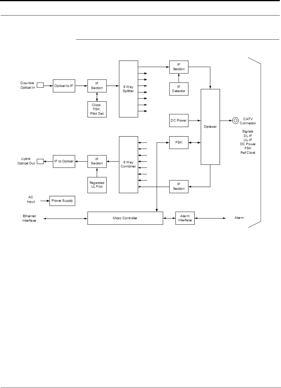
Expansion Hub Overview
4-2 InterReach Fusion Installation, Operation, and Reference Manual
CONFIDENTIAL
D-620610-0-20 Rev A
Figure 4-2
Expansion Hub Block Diagram
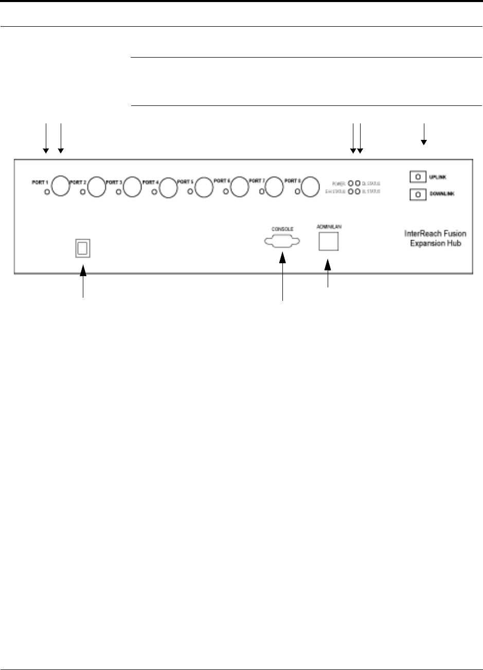
Help Hot Line (U.S. only): 1-800-530-9960 4-3
D-620610-0-20 Rev A
CONFIDENTIAL
Expansion Hub Front Panel
4.2 Expansion Hub Front Panel
Figure 4-3
Expansion Hub Front Panel
1.
One port LED per type F connector port for link status and downstream RAU sta-
tus (8 pair total).
2.
Eight CATV cable, type F connectors (labeled
PORT 1
,
2
,
3
,
4
,
5
,
6
,
7
,
8
)
3.
One pair of unit status LEDs
• One LED for unit power status (labeled
POWER
)
• One LED for unit status (labeled
E-HUB STATUS
)
4.
One set of fiber connection status LEDs
• One LED for fiber downlink status (labeled
DL STATUS
)
• One LED for fiber uplink status (labeled
UL STATUS
)
5.
One fiber optic port which has two connectors
• One standard female SC/APC connector for MMF/SMF output (labeled
UPLINK
)
• One standard female SC/APC connector for MMF/SMF input (labeled
DOWNLINK
)
6.
One 9-pin D-sub male connector for LGC factory testing (labeled
CONSOLE
)
7.
One RJ-45 female connector for system communication and diagnostics using a
PC/laptop with direct connect or using a LAN switch (labeled
ADMIN/LAN
)
8.
Power Switch
1 2 3 4 5
86
7

Expansion Hub Front Panel
4-4 InterReach Fusion Installation, Operation, and Reference Manual
CONFIDENTIAL
D-620610-0-20 Rev A
4.2.1 75 Ohm Type F Connectors
The eight type F connectors on the Expansion Hub are for the CATV cables used to
transmit and receive signals to and from RAUs. Use only 75 ohm type F connectors
on the CATV cable.
The CATV cable also delivers DC electrical power to the RAUs. The Expansion
Hub’s DC voltage output is 54V DC nominal. A current limiting circuit protects the
Hub if any port draws excessive power.
NOTE: For system performance, it is important to use only low loss solid cop-
per center conductor CATV cable with quality type F connectors that use captive
centerpin connectors. Refer to Appendix A for approved cables and connectors.
4.2.2 Manufacturing RS-232 Serial Connector
Console Port
This console port is only used by LGC Wireless manufacturing test purposes. DO
NOT CONNECT ANYTHING TO IT.
Local Monitoring
Use a crossover Ethernet cable (PN-4069-ADB) to directly connect a laptop or PC to
the RJ-45 female connector for local monitoring or configuring the Expansion Hub
and associated RAUs using the AdminBrowser-EH resident software. The cable typi-
cally has a RJ-45 male connector on both ends. Refer to Appendix A.4 on page A-8
for the cable pinout and the AdminBrowser manual.
4.2.3 Optical Fiber Uplink/Downlink Connectors
The optical fiber uplink/downlink port transmits and receives optical signals between
the Expansion Hub and the Main Hub using industry-standard SMF or MMF cable.
The fiber port has two female SC/APC connectors:
• Optical Fiber Uplink Connector
This connector (labeled
UPLINK
) is used to transmit (output) uplink optical signals
to the Main Hub.
• Optical Fiber Downlink Connector
This connector (labeled
DOWNLINK
) is used to receive (input) downlink optical sig-
nals from the Main Hub.
CAUTION: To avoid damaging the Expansion Hub’s fiber connector
ports, use only SC/APC fiber cable connectors. Additionally, use only
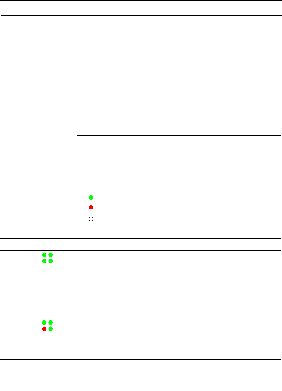
Help Hot Line (U.S. only): 1-800-530-9960 4-5
D-620610-0-20 Rev A
CONFIDENTIAL
Expansion Hub Front Panel
SC/APC fiber connectors throughout the fiber network, including fiber distribu-
tion panels. This is critical for ensuring system performance.
4.2.4 LED Indicators
The unit’s front panel LEDs indicate fault conditions and commanded or fault lockouts.
The LEDs do not indicate warnings or whether the system test has been performed.
Only use the LEDs to provide basic information or as a backup when you are not using
AdminBrowser.
Upon power up, the Expansion Hub goes through a five-second test to check the LED
lamps. During this time, the LEDs blink through the states shown in Table 4-2, letting
you visually verify that the LED lamps and the firmware are functioning properly.
NOTE: Refer to Section 9 for troubleshooting using the LEDs.
Unit Status and DL/UL Status LEDs
The Expansion Hub unit status and DL/UL status LEDs can be in one of the states
shown in Table 4-1. These LEDs can be:
steady green
steady red
off
Table 4-1
Expansion Hub Unit Status and DL/UL Status LED States
LED State Indicates
Green / Green
Green / Green
• The Expansion Hub is connected to power and all power supplies are
operating.
• The Expansion Hub is not reporting a fault or lockout condition; but
the system test may need to be performed or a warning condition
could exist (use AdminManager to determine this).
• Optical power received is above minimum (the Main Hub is con-
nected) although the cable optical loss may be greater than recom-
mended maximum.
• Optical power transmitted (uplink laser) is normal and communica-
tions with the Main Hub are normal.
Green / Green
Red / Green
• Optical power received is above minimum (the Main Hub is con-
nected) although the cable optical loss may be greater than recom-
mended maximum.
• Optical power transmitted (uplink laser) is normal and communica-
tions with the Main Hub are normal.
• The Expansion Hub is reporting a fault or commanded lockout.
POWER
EH STATUS
DL STATUS
UL STATUS
POWER
EH STATUS
DL STATUS
UL STATUS
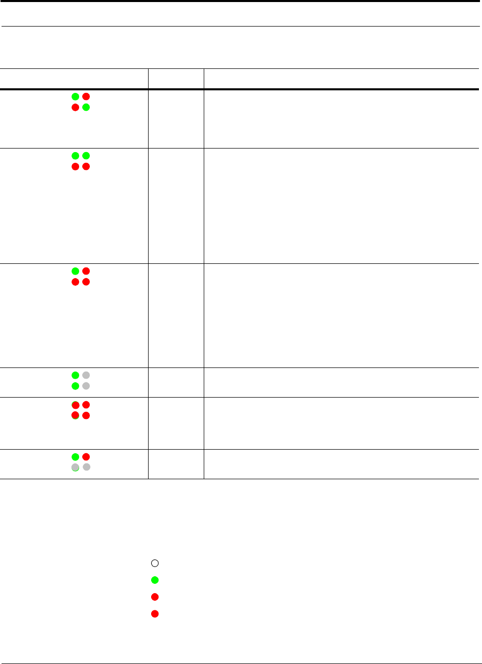
Expansion Hub Front Panel
4-6 InterReach Fusion Installation, Operation, and Reference Manual
CONFIDENTIAL
D-620610-0-20 Rev A
RJ-45 Port LEDs
The Expansion Hub has a port LED, labeled
PORT
, for each of the eight 75 Ohm,
Type F ports. The port LEDs can be in one of the states shown in Table 4-2. These
LEDs can be:
off
steady green
steady red
flashing red (60 pulses per minute [PPM])
Green / Red
Red / Green
• A fault condition was detected, optical power received is below mini-
mum.
(the Main Hub is not connected, is not powered, or the Main Hub’s
downlink laser has failed, or the downlink fiber is disconnected or
damaged.)
Green / Green
Red / Red
• The Expansion Hub is reporting a fault condition.
• Optical power received is above minimum (Main Hub is connected)
although the cable optical loss may be greater than recommended
maximum.
• Optical power transmitted is below minimum (Expansion Hub uplink
laser has failed; unable to communicate with Main Hub).
UL STATUS
LED state must be checked within the first 90 seconds after power on.
If initially green, then red after 90 seconds, it means that there is no
communication with the Main Hub. If red on power up, replace the
Expansion Hub.
Green / Red
Red / Red
• Optical power received is below minimum (the Main Hub is not con-
nected, is not powered, or the Main Hub’s downlink laser has failed,
or the downlink fiber is disconnected or damaged.)
• Optical power transmitted is below minimum (the Expansion Hub
uplink laser has failed; is unable to communicate with the Main Hub).
UL STATUS
LED state must be checked within the first 90 seconds
after power on. If initially green, then red after 90 seconds, it means
that there is no communication with the Main Hub. If red on power
up, the uplink laser has failed, replace the Expansion Hub.
Green /Off
Green / Off
• Expansion Hub is in factory test mode, return it to the factory.
Red/ Don’t
Care
Red/ Don’t
Care
• One or more power supplies are out of specification. The hub needs to
be replaced.
Green/ Red
Off/ Off
• Expansion Hub failure. The Hub must be replaced.
Table 4-1
Expansion Hub Unit Status and DL/UL Status LED States (continued)
LED State Indicates
POWER
EH STATUS
DL STATUS
UL STATUS
POWER
EH STATUS
DL STATUS
UL STATUS
POWER
EH STATUS
DL STATUS
UL STATUS
POWER
EH STATUS
DL STATUS
UL STATUS
POWER
EH STATUS
DL STATUS
UL STATUS
POWER
EH STATUS
DL STATUS
UL STATUS
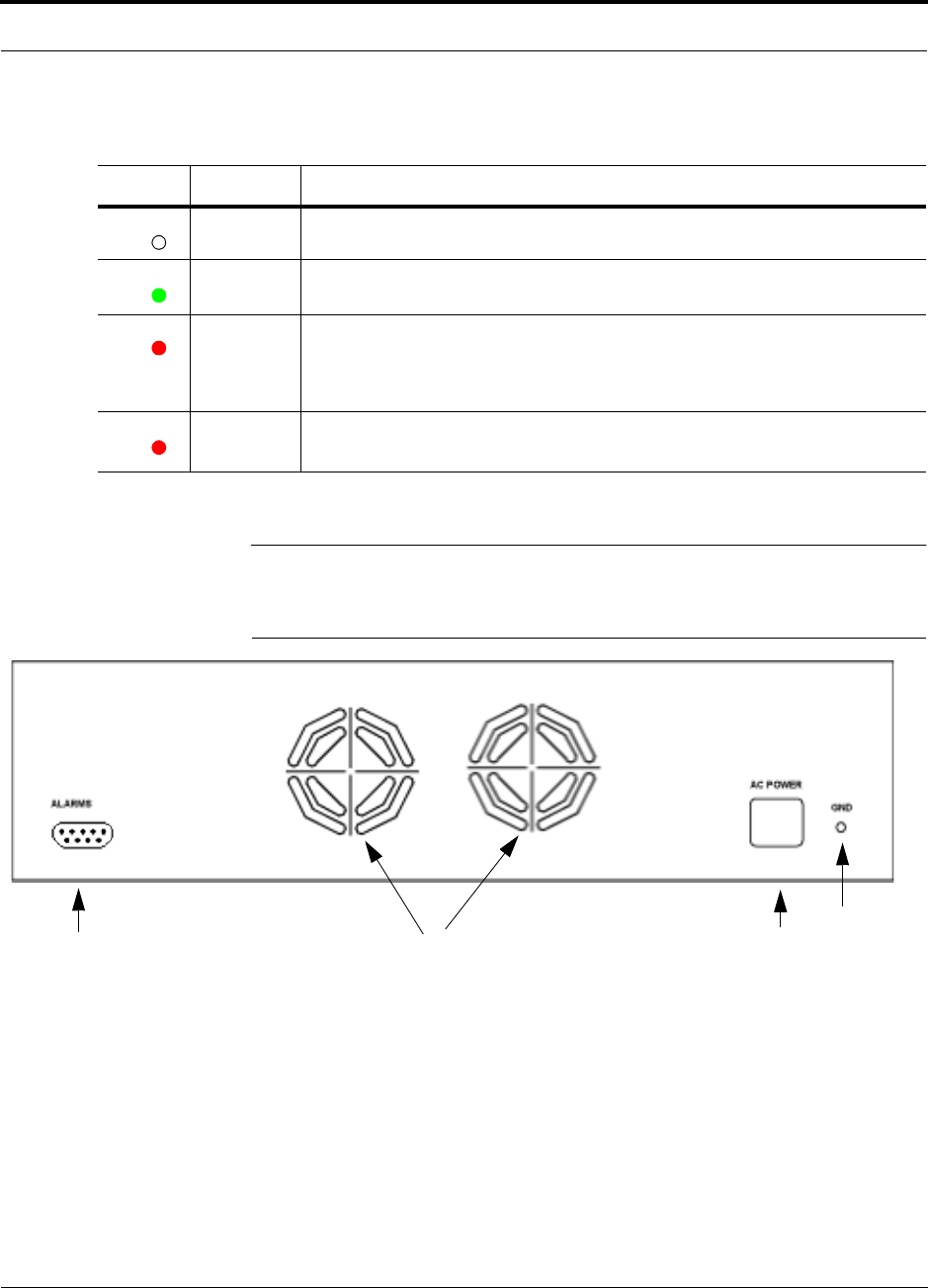
Help Hot Line (U.S. only): 1-800-530-9960 4-7
D-620610-0-20 Rev A
CONFIDENTIAL
Expansion Hub Rear Panel
4.3 Expansion Hub Rear Panel
Figure 4-4
Expansion Hub Rear Panel
1.
AC power cord connector
2.
Two air exhaust vents
3.
One 9-pin D-sub female connector for contact alarm monitoring (labeled
ALARMS
)
4.
Ground lug for connecting unit to frame ground (labeled
GROUND
)
Table 4-2
Fusion Expansion Hub Port LED States
LED State Indicates
Off • The RAU is not connected.
Green
• The RAU is connected.
• No faults from the RAU.
Red
(60 PPM)
• The RAU was disconnected.
• The RAU is not communicating.
• The RAU port power is tripped.
Red
(Steady)
• The RAU is disconnected.
• The RAU is reporting a fault or lockout condition.
PORT
PORT
PORT
PORT
1234

Faults, Warnings, and Status Messages
4-8 InterReach Fusion Installation, Operation, and Reference Manual
CONFIDENTIAL
D-620610-0-20 Rev A
Table 4-3
9-pin D-sub Pin Connector Functions
This interface can monitor three single external alarm contacts (Alarm Sense Input 1
This interface monitors the output contact closures from a Universal Power Supply
(UPS). Verify the output contact closure state (normally closed or normally open) of
the UPS, and set the appropriate contact definition using AdminBrowser.
• Faults are service impacting.
• Warnings indicate a possible service impact.
• Status messages are generally not service impacting.through 3).
4.4 Faults, Warnings, and Status Messages
Both fault and warning conditions of the Expansion Hub and attached RAUs are
reported to the Main Hub. Only faults are indicated by LEDs.
For more information, refer to Appendix C, “Faults, Warnings, Status Tables,” on
page C-1.
NOTE: You can select what type of events AdminBrowser displays. Refer
to Section 3.5.2 View Preference 3-12.
Pin Function
1 Alarm Sense Input (DC Ground)
2 Alarm Sense Input 3
3 Alarm Sense Input 2
4 N/C
5 N/C
6 DC Ground (common)
7 N/C
8 Alarm Sense Input 1
9 N/C

Help Hot Line (U.S. only): 1-800-530-9960 4-9
D-620610-0-20 Rev A
CONFIDENTIAL
Expansion Hub Specifications
4.5 Expansion Hub Specifications
Table 4-4
Expansion Hub Specifications
Specification Description
Enclosure Dimensions (H
×
W
×
D) 89 mm x 438 mm x 381 mm
(3.5 in. x 17.25 in. x 15 in.) 2U
Weight < 6.6 kg (< 14.5 lb.)
Operating Temperature 0° to +45°C (+32° to +113°F)
Non-operating Temperature –20° to +85°C (–4° to +185°F)
Operating Humidity, non-condensing 5% to 95%
CATV Connectors
a
a. It is important that you use only recommended CATV 75 Ohm cable with quality F connectors.
8 F, female (CATV - 75 Ohm)
Fiber Connectors
b
b. It is critical to system performance that only SC/APC fiber connectors are used throughout the fiber network, including
fiber distribution panels.
1 Pair, SC/APC
LED Alarm and Status Indicators Unit Status (1 pair):
• Power
• E-Hub Status
Fiber Link Status (1 pair):
• DL Status
• UL Status
Port Status (1 pair per CATV port):
• Link/RAU
External Alarm Connector (contact sense
monitor)
1 9-pin D-sub, female
AC Power (Volts) (47–63 Hz) Rating: 115/230V AC, 6/3A, 50-60 Hz
Operating Range: 90-132V AC/170-250V AC auto-ranging
Power Consumption (W) 4 RAUs: 305 typical
8 RAUs: 530 typical
MTBF 54,477 hours

Expansion Hub Specifications
4-10 InterReach Fusion Installation, Operation, and Reference Manual
CONFIDENTIAL
D-620610-0-20 Rev A

InterReach Fusion Installation, Operation, and Reference Manual 5-1
D-620610-0-20 Rev A
CONFIDENTIAL
SECTION 5
Remote Access Unit
This section contains the following subsections:
• Section 5.1 RAU Overview . . . . . . . . . . . . . . . . . . . . . . . . . . . . . . . . . . . . . . . 5-1
• Section 5.2 Remote Access Unit Connectors . . . . . . . . . . . . . . . . . . . . . . . . . 5-5
• Section 5.3 RAU LED Indicators . . . . . . . . . . . . . . . . . . . . . . . . . . . . . . . . . . 5-6
• Section 5.4 Faults and Warnings . . . . . . . . . . . . . . . . . . . . . . . . . . . . . . . . . . . 5-7
• Section 5.5 Remote Access Unit Specifications . . . . . . . . . . . . . . . . . . . . . . . 5-7
5.1 RAU Overview
The Remote Access Unit (RAU) is an active transceiver that connects to an Expan-
sion Hub using industry-standard CATV cable, which delivers RF signals, configura-
tion information, and electrical power to the RAU.
An RAU passes converted 1F to RF (Downlink) and converted RF to 1F (Uplink) sig-
nals between an Expansion Hub and an attached passive antenna where the signals
are transmitted to wireless devices as shown in Figure 5-1.
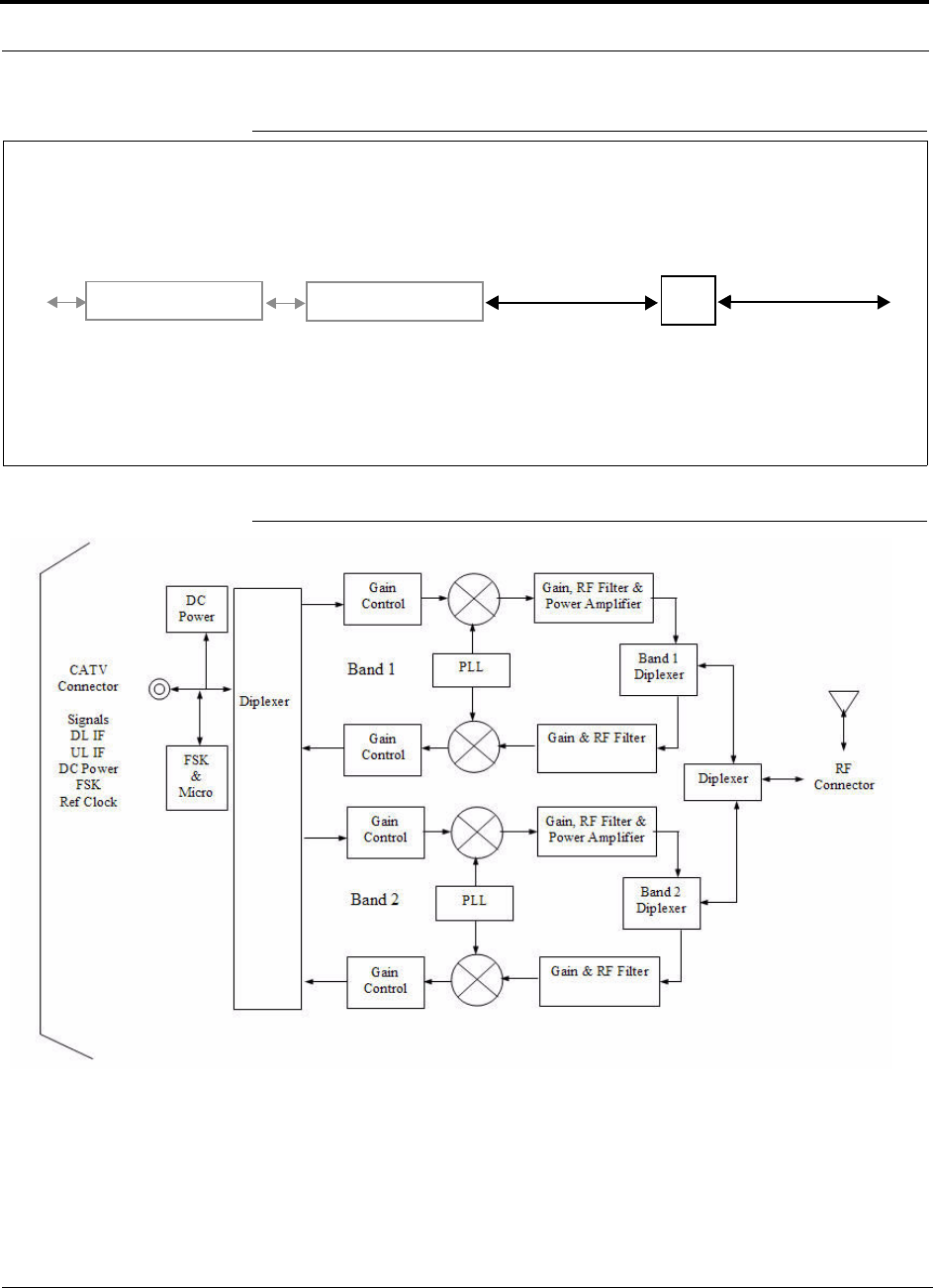
RAU Overview
5-2 InterReach Fusion Installation, Operation, and Reference Manual
CONFIDENTIAL
D-620610-0-20 Rev A
Figure 5-1
Remote Access Unit in a Fusion System
Figure 5-2
Remote Access Unit Block Diagram (Multiband)
Fusion Expansion Hub RAU
Downlink Path: The RAU receives downlink IF signals from a Fusion Hub using 75 Ohm CATV cable. It converts the sig-
nals to RF and sends them to a passive RF antenna using 50 Ohm coaxial cable. Also, the RAU receives configuration
information from the Fusion Hub using the 75 Ohm CATV cable.
Uplink Path: The RAU receives uplink RF signals from a passive RF antenna using 50 Ohm coaxial cable. It converts the
signals to IF and sends them to a Fusion Hub using 75 Ohm CATV cable. Also, the RAU sends its status information to the
Fusion Hub using CATV cable.
The RAU receives 54VDC power from the Fusion Hub port through the 75 Ohm CATV cable center pin.
Downlink to RAU
Uplink from RAU
Fusion Main Hub
Downlink to antenna
Uplink from antenna
,3*
* for FSN-809019-1 RAU when Band 3 is active.

Help Hot Line (U.S. only): 1-800-530-9960 5-3
D-620610-0-20 Rev A
CONFIDENTIAL
RAU Overview
The Fusion RAUs are manufactured to a specific set of bands: one 35 MHz Band 1
(split into two sub-bands 1A and 1B for FSN-809019-1 RAU), and one 75
MHz-Band 2. Table 5-1 lists the Fusion RAUs, the Fusion Band, and the frequency
bands they cover.
Table 5-1
Frequency Bands Covered by Fusion RAUs
Fusion
RAU
Part
Number
Fusion
Band
RF Passband
Downlink
(MHz)
Uplink
(MHz)
MAIN
HUB/
RAU
Band
RAU
Bandwidth
850/1900 FSN-8519-1 850 869–894 824–849 1 25 MHz
1900 1930–1990 1850–1910 2 60 MHz
900//1800 FSN-9018-1 900 925–960 880–915 1 35 MHz
1800 1805–1880 1710–1785 2 75 MHz
900/2100 FSN-9021-1 900 925–960 830–715 1 35 MHz
2100 2110–2170 1920–1980 2 60 MHz
800/900/
1900
FSN-809019
-1
800
SMR
851-869 806-824 1 (sub
band
1A)
18 MHz
900
SMR
935-941 896-902 3 (sub
band
1B)
6 MHz
1900
(A-G)
1930-1995 1850-1915 2 65 MHz

RAU Overview
5-4 InterReach Fusion Installation, Operation, and Reference Manual
CONFIDENTIAL
D-620610-0-20 Rev A
* Exceeding the distance of copper-clad cable will result in the attached RAU becoming
non-functional. If the distance of a cable run is at its maximum and is of concern, LGC recom-
mends the use of solid copper cable to ensure successful operation.
Table 5-2
System Gain (Loss) Relative to CATV Cable Length (All RAUs except
800/900/1900)
Cable
Type
Comm-
Scope
Part
Number
Plenum
Rated
Solid
Copper
Conductor
Copper
Clad
Conductor
Zero-loss
RF
Maximum
Length
(meters)
Distance
RF is
10dB
Below
Input RF
(meters)
RG-59
2065V Yes X 150 210
2022V Yes X 120 120*
5572R No X 110 110*
5565 No X 150 210
RG-6
2279V Yes X 170 230
2275V Yes X 170 175*
5726 No X 170 170*
5765 No X 170 230
RG-11
2293K Yes X 275 375
2285K Yes X 275 370*
5913 No X 275 370*

Help Hot Line (U.S. only): 1-800-530-9960 5-5
D-620610-0-20 Rev A
CONFIDENTIAL
Remote Access Unit Connectors
* Exceeding the distance of copper-clad cable will result in the attached RAU becoming non-functional. If
the distance of a cable run is at its maximum and is of concern, LGC recommends the use of solid copper
cable to ensure successful operation.
5.2 Remote Access Unit Connectors
5.2.1 50 Ohm Type-N Connector
The RAU has one female type-N connector. The connector is a duplexed RF
input/output port that connects to a standard 50Ω passive antenna using coaxial cable.
5.2.2 75 Ohm Type-F Connector
The RAU has one type-F female connector that connects it to a Fusion Hub using
CATV 75 Ohm cable. Use RG-59, 6, or 11 solid copper center conductor cables.
Table 5-3
System Gain (Loss) Relative to CATV Cable Length for RAUs
Cable
Type
Comm-
Scope
Part
Number
Plenum
Rated
Solid
Copper
Conductor
Copper
Clad
Conductor
Zero-loss
RF
Maximum
Length
(meters)
Distance
Where
RF is
10dB
Below
Input RF
(meters)
RG-59
2065V Yes X 150 210
2022V Yes X 80 80*
5572R No X 70 70*
5565 No X 150 210
RG-6
2279V Yes X 170 230
2275V Yes X 115 115*
5726 No X 110 110*
5765 No X 170 230
RG-11
2293K Yes X 275 375
2285K Yes X 240 240*
5913 No X 240 240*
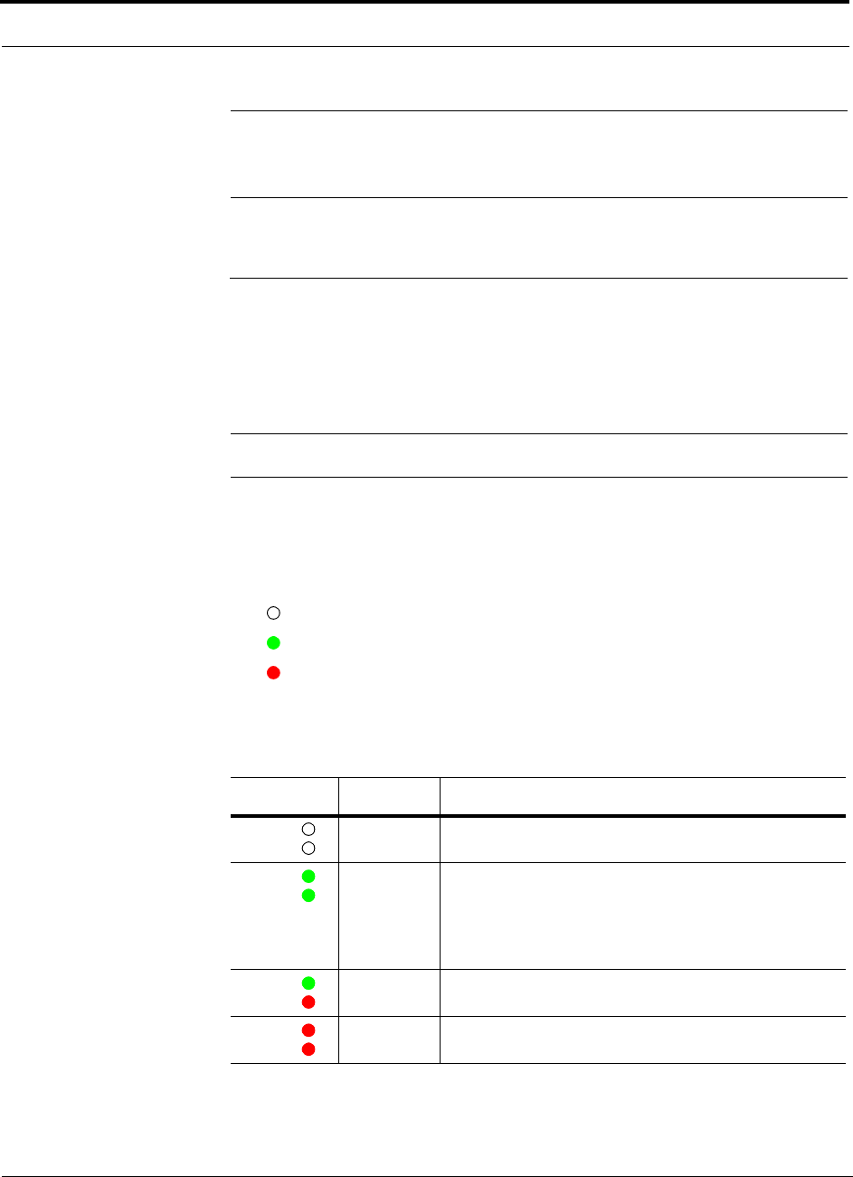
RAU LED Indicators
5-6 InterReach Fusion Installation, Operation, and Reference Manual
CONFIDENTIAL
D-620610-0-20 Rev A
NOTE: For system performance, it is important that you use only low loss,
solid copper center conductor CATV cable with quality F connectors that use
captive centerpin conductors. Refer to Appendix A for specific information.
5.3 RAU LED Indicators
Upon power up, the RAU goes through a two-second test to check the LED lamps.
During this time, the LEDs blink green/green red/red, letting you visually verify that
the LED lamps and the firmware are functioning properly.
NOTE: Refer to Section 9 for troubleshooting using the LEDs.
Status LEDs
The RAU status LEDs can be in one of the states shown in Table 5-4. These LEDs
can be:
off
steady green
steady red
There is no off state when the unit’s power is on.
Table 5-4
Remote Access Unit LED States
LED State Indicates
Off
Off
• The RAU is not receiving DC power.
Green
Green
• The RAU is powered and is not indicating a fault condi-
tion. Communication with the Fusion Hub is normal;
however, the system test may need to be performed or a
warning condition may exist (use AdminBrowser to
determine this).
Green
Red
• The RAU is indicating a fault or lockout condition, but
communication with the Fusion Hub is normal.
Red
Red
• The RAU is reporting a fault or lockout condition and is
not able to communicate with the Fusion Hub
LINK
ALARM
LINK
ALARM
LINK
ALARM
LINK
ALARM

Help Hot Line (U.S. only): 1-800-530-9960 5-7
D-620610-0-20 Rev A
CONFIDENTIAL
Faults and Warnings
5.4 Faults and Warnings
Both fault and warning conditions are reported to the Fusion Hub where they are
stored. Only faults are indicated by the faceplate LEDs.
For more information, refer to Appendix C.
5.5 Remote Access Unit Specifications
NOTE: For system performance, it is important that you use only low loss,
solid copper center conductor CATV cable with quality F connectors that use
captive centerpin conductors. Refer to Appendix A for more information.
Table 5-5
Remote Access Unit Specifications
Specification Description
Dimensions (H
×
W
×
D) 133.5 mm × 438 mm × 381 mm
(5.25 in. × 17.25 in. × 15 in.)
Weight < 2.1 kg (< 4.6 lb.)
Operating Temperature –25° to +45°C (–13° to +113°F)
Non-operating Temperature –25° to +85°C (–13° to +185°F)
Operating Humidity, non-condensing 5% to 95%
RF Connectors One Type-F, female (CATV - 75 ohms)
One Type-N, female (coaxial 50 ohms)
LED Alarm and Status Indicators Unit Status (1 pair):
• Link
• Alarm
Maximum Heat Dissipation (W) 50 typical, 64 max (from the Hub)
MTBF 211,600 hours (All Dual Band RAUs)
144,409 hours (800/900/1900 Tri-Band RAUs)

Remote Access Unit Specifications
5-8 InterReach Fusion Installation, Operation, and Reference Manual
CONFIDENTIAL
D-620610-0-20 Rev A

InterReach Fusion Installation, Operation, and Reference Manual 6-1
D-620610-0-20 Rev A
CONFIDENTIAL
SECTION 6
Designing a Fusion Solution
This section contains the following subsections:
• Section 6.1 Overview . . . . . . . . . . . . . . . . . . . . . . . . . . . . . . . . . . . . . . . . . . . 6-1
• Section 6.2 Downlink RSSI Design Goal . . . . . . . . . . . . . . . . . . . . . . . . . . . . 6-3
• Section 6.3 Maximum Output Power per Carrier . . . . . . . . . . . . . . . . . . . . . . 6-4
• Section 6.4 System Gain . . . . . . . . . . . . . . . . . . . . . . . . . . . . . . . . . . . . . . . . 6-11
• Section 6.5 Estimating RF Coverage . . . . . . . . . . . . . . . . . . . . . . . . . . . . . . 6-14
• Section 6.6 Link Budget Analysis . . . . . . . . . . . . . . . . . . . . . . . . . . . . . . . . . 6-25
• Section 6.7 Optical Power Budget . . . . . . . . . . . . . . . . . . . . . . . . . . . . . . . . 6-37
• Section 6.8 Connecting a Main Hub to a Base Station . . . . . . . . . . . . . . . . . 6-38
6.1 Overview
Designing a Fusion solution is a matter of determining coverage and capacity needs.
This requires the following steps:
1.
Determine the wireless service provider’s requirements: Refer to Section 6.2,
“Downlink RSSI Design Goal,” on page 6-3.
The following information is typically provided by the service provider:
• Frequency (for example, 1900 MHz)
• Band (for example, “A-F” band in the PCS spectrum)
• Protocol (for example, CDMA, GSM, 1xRTT, GPRS, and so on)
• Number of sectors and peak capacity per sector (translates to the number of RF
carriers that the system will have to transmit)
• Downlink RSSI design goal (RSSI, received signal strength at the wireless
handset, for example, –85 dBm)

Overview
6-2 InterReach Fusion Installation, Operation, and Reference Manual
CONFIDENTIAL
D-620610-0-20 Rev A
The design goal is always a stronger signal than the mobile phone needs. It
includes inherent factors which affect performance.
• RF source (base station or bidirectional amplifier or repeater), type of equip-
ment if possible.
2.
Determine the downlink power per carrier from the RF source through the
DAS: Refer to Section 6.3, “Maximum Output Power per Carrier,” on page
6-4.
The maximum power per carrier is a function of modulation type, the number of
RF carriers, signal quality issues, regulatory emissions requirements, and Fusion’s
RF performance. Power per carrier decreases as the number of carriers increases.
3.
Develop an RF link budget: Refer to Section 6.5, “Estimating RF Coverage,”
on page 6-14.
Knowing both the power per carrier and RSSI design goal, you can develop an RF
downlink link budget which estimates the allowable path loss from an RAU’s
antenna to the wireless handset.
allowable path loss = power per carrier + antenna gain – design goal
Satisfactory performance can be expected as long as path loss is below this level.
4.
Determine the in-building environment: Refer to Section 6.5, “Estimating
RF Coverage,” on page 6-14.
• Determine which areas of the building require coverage (entire building, public
areas, parking levels, and so on.)
• Obtain floor plans to determine floor space of building and the wall layout of
the proposed areas to be covered. Floor plans are also useful when you are
selecting antenna locations.
• If possible, determine the building’s construction materials (sheetrock, metal,
concrete, and so on.)
• Determine the type of environment:
– Open layout (for example, a convention center)
– Dense, close walls (for example, a hospital)
– Mixed use (for example, an office building with hard wall offices and cubi-
cles)
5.
Determine the appropriate estimated path loss slope that corresponds to the
type of building and its layout, and estimate the coverage distance for each
RAU: Refer to Section 6.5, “Estimating RF Coverage,” on page 6-14.
Use the path loss slope (PLS), which gives a value to the RF propagation charac-
teristics within the building, to convert the RF link budget into an estimate of the
coverage distance per antenna. This helps establish the quantities of Fusion equip-
ment you need. The actual path loss slope that corresponds to the specific RF
environment inside the building can also be determined empirically by perform-
ing an RF site-survey of the building. This involves transmitting a calibrated tone
for a fixed antenna and making measurements with a mobile antenna throughout
the area surrounding the transmitter.

Help Hot Line (U.S. only): 1-800-530-9960 6-3
D-620610-0-20 Rev A
CONFIDENTIAL
Downlink RSSI Design Goal
6.
Determine the items required to connect to the base station: Refer to
Section 6.8, “Connecting a Main Hub to a Base Station,” on page 6-38.
Once you know the quantities of Fusion equipment to be used, you can determine
the accessories (combiners/dividers, surge suppressors, repeaters, attenuators, cir-
culators, and so on.) required to connect the system to the base station.
The individual elements that must be considered in designing a Fusion solution are
explained in the following sections.
NOTE: Access the LGC Wireless Customer Portal at LGCWireless.com for
on-line dimensioning and design tools.
6.2 Downlink RSSI Design Goal
Wireless service providers typically provide a minimum downlink signal level and an
associated confidence factor when specifying coverage requirements. These two fig-
ures of merit are a function of wireless handset sensitivity and margins for fading and
body loss. Wireless handset sensitivity is the weakest signal that the handset can pro-
cess reliably and is a combination of the thermal noise in the channel, noise figure of
the handset receiver front end and minimum required SNR. Fade margins for multi-
path fading (fast or small-scale) and log-normal shadow fading (slow or large-scale)
are determined by the desired confidence factor, and other factors. Downlink RSSI
design goal calculations for the GSM protocol are shown below for a 95% area cover-
age confidence factor.
Downlink design goals on the order of –85 dBm are typical for protocols, such as
GSM and iDEN. Wireless service providers may choose a higher level to ensure that
in-building signal dominates any macro signal that may be leaking into the building.
Noise Power
10 Log (KT)+10 Log (200 KHz); K=1.38X10
–23
, T=300 degrees Kelvin
–121 dBm
Wireless Handset Noise Figure 8 dB
Required SNR 9 dB
Multipath Fade Margin
95% Reliability for Rician K=6 dB
6 dB
Log-normal Fade Margin
95% Area/87% Edge Reliability for 35 dB PLS and 9 dB Sigma
10 dB
Body Attenuation + 3 dB
Downlink RSSI Design Goal (P
DesignGoal
)
Signal level received by wireless handset at edge of coverage area
–85 dBm
Maximum Output Power per Carrier
6-4 InterReach Fusion Installation, Operation, and Reference Manual
CONFIDENTIAL
D-620610-0-20 Rev A
6.3 Maximum Output Power per Carrier
The following tables show the recommended maximum power per carrier out of the
RAU 50 Ohm Type-N connector for different frequencies, protocols, and numbers of
carriers. These maximum levels are dictated by RF signal quality and regulatory
emissions issues. In general, as the number of RF carrier increases, the maximum
power per carrier decreases. If these levels are exceeded, signal quality will be
degraded and/or regulator requirements will be violated. The maximum input power
to the Hub is determined by subtracting the system gain from the maximum output
power of the RAU. System gain is software selectable from 0 dB to 15 dB in 1 dB
steps. Additionally, both the uplink and downlink gain of each RAU can be reduced
by 10 dB in 1 dB steps.
When connecting a Hub to a base station or repeater, attenuation on the downlink is
typically required to avoid exceeding Fusion’s maximum output power recommenda-
tions.
WARNING: Exceeding the maximum input power may cause perma-
nent damage to the Hub. Do not exceed the maximum composite input
power of 1W (+30 dBm) to the Hub at any time.
NOTE: These specifications are for downlink power at the RAU output (excluding
antenna).

Help Hot Line (U.S. only): 1-800-530-9960 6-5
D-620610-0-20 Rev A
CONFIDENTIAL
Maximum Output Power per Carrier
6.3.1 850 MHz Cellular
Cellular Power per Carrier
No. of
Carriers
Power per Carrier (dBm)
AMPS TDMA GSM EDGE CDMA WCDMA
1 16.5 16.5 16.5 16.5 16 15
2
16.5 16.5 13.5 13.5 13 11
3
16.5 15.0 11.5 11.5 11 8
4
13.5 13 10.0 10.0 10.0 6.5
5
12.0 11.5 9.0 9.0 9.0 5.0
6
10.5 10.5 8.5 8.5 8.0
7
9.5 9.5 8.0 8.0 7.5
8
8.5 8.5 7.5 7.5 7.0
9
8.0 8.0 7.0 7.0
10
7.0 7.5 6.5 6.5
11
7.0 7.0 6.5 6.5
12
6.5 6.5 6.0 6.0
13
6.0 6.5 6.5 5.5
14
5.5 6.0 5.5 5.5
15
5.5 5.5 5.0 5.0
16
5.0 5.5 5.0 5.0
20
4.0 4.5 4.5 4.0
30
2.0 2.5 3.0 2.0
Note: Operation at or above these output power levels may prevent Fusion from meeting RF performance specifications or FCC Part 15 and EN55022
emissions requirements.

Maximum Output Power per Carrier
6-6 InterReach Fusion Installation, Operation, and Reference Manual
CONFIDENTIAL
D-620610-0-20 Rev A
6.3.2 800 MHz or 900 MHz SMR
Table 6-1
Power per Carrier
No. of
Carriers
Power per Carrier (dBm) - 800MHz/900 MHz
iDEN Analog FM CQPSK C4FM
DataTac/
Mobitex
POCSAG/
REFLEX
1 16.6/14.5 24.0/23.0 21.0/19.0 24.0/23.0 24.0/23.0 23.0
2
13.0/11.0 19.0/17.0 16.0/14.0 18.5/16.5 18.5/16.5 16.5
3
10.5/8.5 15.5/13.5 13.5/11.5 15.0/13.0 15.0/13.0 13.0
4
9.0/7.0 12.5/10.0 11.5/9.5 12/510.5 12.5/10.5 10.5
5
8.0/6.0 11.0/9.0 10.0/8.0 10.5/8.5
6
7.0/5.0 9.5/7.5 8.5/6.5 9.0/7.0
7
6.0/4.0 8.5/6.5 8.0/6.0 8.0/6.0
8
5.5/3.5 7.5/5.5 7.0/5.0 7.5/5.5
9
5.0/3.0 7.0/8.0 6.5/4.5 6.5/4.5
10
4.5/2.5 6.0/4.0 6.0/4.0 6.0/4.0
11
4.0/2.0
12
3.5/1.5
13
3.0/1.0
14
3.0/1.0
15
2.5/0.5
16
2.0/0
Note: Operation at or above these output power levels may prevent Fusion from meeting RF performance specifications or FCC Part 15 and EN55022 emissions requirements.

Help Hot Line (U.S. only): 1-800-530-9960 6-7
D-620610-0-20 Rev A
CONFIDENTIAL
Maximum Output Power per Carrier
6.3.3 900 MHz EGSM and EDGE
Table 6-2
GSM/EGSM and EDGE Power per Carrier
No. of
Carriers
Power per Carrier (dBm)
GSM EDGE
1 16.0 16.0
2 13.0 13.0
3 11.0 11.0
4 10.0 10.0
5 9.0 9.0
6 8.0 8.0
7 7.5 7.5
8 7.0 7.0
9 6.5 6.5
10 6.0 6.0
11 5.5 5.5
12 5.0 5.0
13 5.0 5.0
14 4.5 4.5
15 4.0 4.0
16 4.0 4.0
20 3 3
30 1 1
Note: Operation at or above these output power levels may prevent Fusion
from meeting RF performance specifications or FCC Part 15 and EN55022
emissions requirements.

Maximum Output Power per Carrier
6-8 InterReach Fusion Installation, Operation, and Reference Manual
CONFIDENTIAL
D-620610-0-20 Rev A
6.3.4 1800 MHz DCS
Table 6-3
DCS Power per Carrier
No. of
Carriers
Power per Carrier (dBm)
GSM EDGE
1 16.5 16.5
2 14.5 14.5
3 12.5 12.5
4 11.5 11.5
5 10.5 10.5
6 9.5 9.5
7 9.0 9.0
8 8.5 8.0
9 8.0 7.5
10 7.5 7.0
11 7.0 6.5
12 6.5 6.0
13 6.5 6.0
14 6.0 5.5
15 5.5 5.0
16 5.5 5.0
20 4.5 4.0
30 2.5 2.0
Note: Operation at or above these output power levels may pre-
vent Fusion from meeting RF performance specifications or FCC
Part 15 and EN55022 emissions requirements.
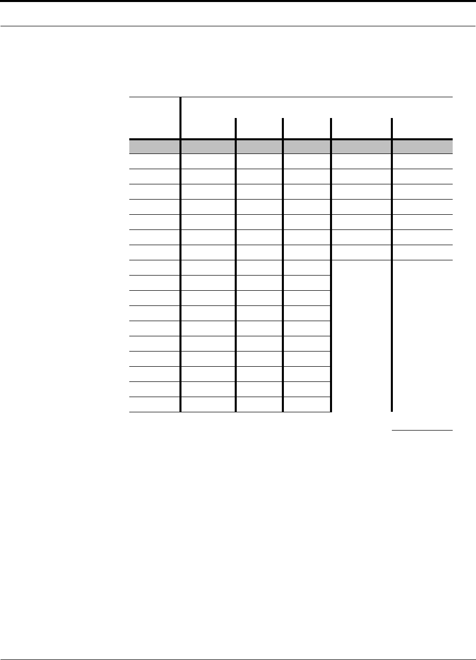
Help Hot Line (U.S. only): 1-800-530-9960 6-9
D-620610-0-20 Rev A
CONFIDENTIAL
Maximum Output Power per Carrier
6.3.5 1900 MHz PCS
Table 6-4
PCS Power per Carrier
No. of
Carriers
Power per Carrier (dBm)
TDMA GSM EDGE CDMA WCDMA
1 16.5 16.5 16.5 16.0 15.0
2
16.5 15.5 15.5 13.0 11.0
3
15.0 13.5 13.5 11.0 8.0
4
13.0 12.0 12.0 10.0 6.5
5
11.5 11.0 10.5 9.0 5.0
6
10.5 10.5 9.5 8.0
7
9.5 10.0 9.0 7.5
8
8.5 9.0 8.0 7.0
9
8.0 8.5 7.5
10
7.5 8.0 7.0
11
7.0 7.5 6.5
12
6.5 7.0 6.0
13
6.5 6.5 6.0
14
6.0 6.5 5.5
15
5.5 6.0 5.0
16
5.5 5.5 5.0
20
4.5 4.5 4.0
30
2.5 3.0 2.0
Note: Operation at or above these output power levels may prevent Fusion from meeting RF perfor-
mance specifications or FCC Part 15 and EN55022 emissions requirements.

Maximum Output Power per Carrier
6-10 InterReach Fusion Installation, Operation, and Reference Manual
CONFIDENTIAL
D-620610-0-20 Rev A
6.3.6 2.1 GHz UMTS
Designing for Capacity Growth
Fusion systems are deployed to enhance in-building coverage and/or to off-load
capacity from a macro cell site. In many instances, subscriber usage increases with
time and the wireless provider responds by increasing the load on the installed Fusion
system. For example, the initial deployment might only require two RF carriers, but
four RF carriers may be needed in the future based on capacity growth forecasts.
There are two options for dealing with this scenario:
1.
Design the initial coverage with a maximum power per carrier for four RF carri-
ers. This will likely result in additional RAUs.
2.
Design the initial coverage for two RF carriers, but reserve RAU ports on the Hub
for future use. These ports can be used to fill potential coverage holes once the
power per carrier is lowered to accommodate the two additional carriers.
Table 6-5
UMTS Power per Carrier
No. of
Carriers
Power per
Carrier (dBm)
WCDMA
1
15.0
2 11.0
3 8.0
4 6.5
5 5.0
6 4.0
7 3.0
Note: measurements taken with no baseband clipping.
Note: Operation at or above these output power levels may prevent Fusion from meet-
ing RF performance specifications or FCC Part 15 and EN55022 emissions require-
ments.

Help Hot Line (U.S. only): 1-800-530-9960 6-11
D-620610-0-20 Rev A
CONFIDENTIAL
System Gain
6.4 System Gain
The system gain of the Fusion defaults to 0 dB or can be set up to 15 dB in 1 dB
increments. In addition, uplink and downlink gains of each RAU can be indepen-
dently decreased by 10 dB in one dB steps using AdminBrowser.
The recommended maximum lengths of CATV cable are as follows:
• For RG-59 cable 150 meters for CommScope PN 2065V.
• For RG-6 cable 170 meters for CommScope PN 2279V.
• For RG-11 cable 275 meters for CommScope PN 2293K.
If the maximum distance is not required, then copper-clad over steel center-conductor
cable may be use to reduce cable costs.
If the CATV cable is longer than the recommended distance per cable type, the gain
of the system will decrease, as shown in Table 6-6 and Table 6-7.

System Gain
6-12 InterReach Fusion Installation, Operation, and Reference Manual
CONFIDENTIAL
D-620610-0-20 Rev A
* Exceeding the distance of copper-clad cable will result in the attached RAU becoming non-functional. If
the distance of a cable run is at its maximum and is of concern, LGC recommends the use of solid copper
cable to ensure successful operation.
Table 6-6
System Gain (Loss) Relative to CATV Cable Length (All RAUs except
800/900/1900)
Cable
Type
Comm-
Scope
Part
Number
Plenum
Rated
Solid
Copper
Conductor
Copper
Clad
Conductor
Zero-loss
RF
Maximum
Length
(meters)
Distance
Where
RF is
10dB
Below
Input RF
(meters)
RG-59
2065V Yes X 150 210
2022V Yes X 120 120*
5572R No X 110 110*
5565 No X 150 210
RG-6
2279V Yes X 170 230
2275V Yes X 170 175*
5726 No X 170 170*
5765 No X 170 230
RG-11
2293K Yes X 275 375
2285K Yes X 275 370*
5913 No X 275 370*

Help Hot Line (U.S. only): 1-800-530-9960 6-13
D-620610-0-20 Rev A
CONFIDENTIAL
System Gain
* Exceeding the distance of copper-clad cable will result in the attached RAU becoming non-functional. If
the distance of a cable run is at its maximum and is of concern, LGC recommends the use of solid copper
cable to ensure successful operation.
Table 6-7
System Gain (Loss) Relative to CATV Cable Length for 800/900/1900
RAUs
Cable
Type
Comm-
Scope
Part
Number
Plenum
Rated
Solid
Copper
Conductor
Copper
Clad
Conductor
Zero-loss
RF
Maximum
Length
(meters)
Distance
Where
RF is
10dB
Below
Input RF
(meters)
RG-59
2065V Yes X 150 210
2022V Yes X 80 80*
5572R No X 70 70*
5565 No X 150 210
RG-6
2279V Yes X 170 230
2275V Yes X 115 115*
5726 No X 110 110*
5765 No X 170 230
RG-11
2293K Yes X 275 375
2285K Yes X 240 240*
5913 No X 240 240*
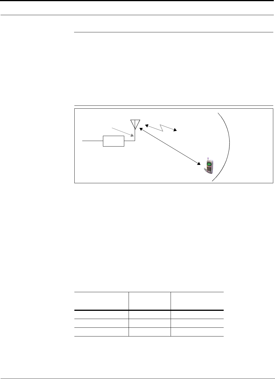
Estimating RF Coverage
6-14 InterReach Fusion Installation, Operation, and Reference Manual
CONFIDENTIAL
D-620610-0-20 Rev A
6.5 Estimating RF Coverage
The maximum output power per carrier (based on the number and type of RF carriers
being transmitted) and the minimum acceptable received power at the wireless device
(that is, the RSSI design goal) essentially establish the RF downlink budget and, con-
sequently, the maximum allowable path loss (APL) between the RAU’s antenna and
the wireless device. Since in-building systems, such as the Fusion, are generally
downlink-limited, this approach is applicable in the majority of deployments.
Figure 6-1
Determining APL between the Antenna and the Wireless Device
APL = (P – L
coax
+ G) – RSSI (1)
where:
• APL = the maximum allowable path loss in dB
• P = the power per carrier transmitted by the RAU in dBm
• L
coax
= the coaxial cable loss between the RAU and passive antenna in dB
• G = the gain of the passive antenna in dBi
Coaxial cable is used to connect the RAU to an antenna. Table 6-8 lists coaxial cable
loss for various cable lengths.
You can calculate the distance, d, corresponding to the maximum allowable path loss
using equations introduced in the following sections.
Table 6-8
Coaxial Cable Losses (
L
coax)
Length of Cable
(.195 in. diameter)
Loss at
850 MHz (dB)
Loss at
1900 MHz (dB)
0.9 m (3 ft) 0.6 0.8
1.8 m (6 ft) 1.0 1.5
3.0 m (10 ft) 1.5 2.3
RAU
P = power per Distance = d
G = Antenna Gain
RSSI = power at the
wireless device
carrier from the RAU
L
coax
= Coaxial cable loss

Help Hot Line (U.S. only): 1-800-530-9960 6-15
D-620610-0-20 Rev A
CONFIDENTIAL
Estimating RF Coverage
6.5.1 Path Loss Equation
In-building path loss obeys the distance power law
1
in equation (2):
PL = 20log
10
(4πd
0
f/c) + 10nlog
10
(d/d
0
) +
Χ
s
(2)
where:
• PL is the path loss at a distance, d, from the antenna
• d = the distance expressed in meters
• d
0
= free-space path loss distance in meters
• f = the operating frequency in Hertz.
• c = the speed of light in a vacuum (3.0 × 10
8
m/sec).
•n = the path loss exponent and depends on the building “clutter” and frequency
of operation
•
Χ
s
= a normal random variable that depends on partition material and geome-
tries inside the building and is accounted for by the log-normal fade margin
used in the downlink RSSI design goal calculation
As a reference, Table 6-9 provides estimates of signal loss for some RF barriers
1
.
1. Rappaport, Theodore S. Wireless Communications, Principles, and Practice. Prentice Hall PTR, 1996.
Table 6-9
Average Signal Loss of Common Building Materials
Partition Type Loss (dB) Frequency (MHz)
Metal wall 26 815
Aluminum siding 20 815
Foil insulation 4 815
Cubicle walls 1.4 900
Concrete block wall 13 1300
Concrete floor 10 1300
Sheetrock 1 to 2 1300
Light machinery 3 1300
General machinery 7 1300
Heavy machinery 11 1300
Equipment racks 7 1300
Assembly line 6 1300
Ceiling duct 5 1300
Metal stairs 5 1300

Estimating RF Coverage
6-16 InterReach Fusion Installation, Operation, and Reference Manual
CONFIDENTIAL
D-620610-0-20 Rev A
6.5.2 RAU Coverage Distance
Use equations (1) and (2), on pages 6-14 and 6-15, respectively, to estimate the dis-
tance from the antenna to where the RF signal decreases to the minimum acceptable
level at the wireless device.
With d
0
set to one meter and path loss slope (PLS) defined as 10n, Equation (2) can
be simplified to:
PL(d) = 20log
10
(4πf/c) + PLS·log
10
(d) (3)
Table 6-10 gives the value of the first term of Equation (3) (that is., (20log
10
(4πf/c))
for various frequency bands.
Table 6-10
Frequency Bands and the Value of the First Term in Equation (3)
Frequency
Band (MHz) Mid-Band
Frequency
(MHz) 20log
10
(4πf/c)
Uplink Downlink
800 MHz SMR 806-824 851-869 838 30.9
900 MHz SMR 896-902 935-941 919 31.9
850 MHz Cellular 824–849 869–894 859 31.1
900 MHz GSM 890–915 935–960 925 31.8
900 MHz EGSM 880–915 925–960 920 31.7
1800 MHz DCS 1710–1785 1805–1880 1795 37.5
1900 MHz PCS 1850–1910 1930–1990 1920 38.1
2.1 GHz UMTS 1920–1980 2110–2170 2045 38.7

Help Hot Line (U.S. only): 1-800-530-9960 6-17
D-620610-0-20 Rev A
CONFIDENTIAL
Estimating RF Coverage
Table 6-11 shows estimated PLS for various environments that have different “clut-
ter” (that is, objects that attenuate the RF signals, such as walls, partitions, stairwells,
equipment racks, and so.).
By setting the path loss to the maximum allowable level (PL = APL), equation (3) can
be used to estimate the maximum coverage distance of an antenna connected to an
RAU, for a given frequency and type of in-building environment.
d = 10^((APL - 20log
10
(4πf/c))/PLS) (4)
For reference, Tables 6-13 through 6-17 show the distance covered by an antenna for
various in-building environments. The following assumptions were made:
• Path loss Equation (4)
• 6 dBm output per carrier at the RAU output
• 3 dBi antenna gain
• RSSI design goal = –85 dBm (typical for narrowband protocols, but not for
spread-spectrum protocols)
Table 6-11
Estimated Path Loss Slope for Different In-Building Environments
Environment Type Example
PLS for
850/900 MHz
PLS for
1800/1900 MHz
Open Environment
very few RF obstructions
Parking Garage, Convention Center 33.7 30.1
Moderately Open Environment
low-to-medium amount of RF
obstructions
Warehouse, Airport, Manufacturing 35 32
Mildly Dense Environment
medium-to-high amount of RF
obstructions
Retail, Office Space with approxi-
mately 80% cubicles and 20% hard
walled offices
36.1 33.1
Moderately Dense Environment
medium-to-high amount of RF
obstructions
Office Space with approximately
50% cubicles and 50% hard walled
offices
37.6 34.8
Dense Environment
large amount of RF obstructions
Hospital, Office Space with approxi-
mately 20% cubicles and 80% hard
walled offices
39.4 38.1

Estimating RF Coverage
6-18 InterReach Fusion Installation, Operation, and Reference Manual
CONFIDENTIAL
D-620610-0-20 Rev A
Table 6-12
Approximate Radiated Distance from Antenna
for 800 MHz SMR Applications
Environment Type
Distance from Antenna
Meters Feet
Open Environment 75 244
Moderately Open Environment 64 208
Mildly Dense Environment 56 184
Moderately Dense Environment 48 156
Dense Environment 40 131
Table 6-13
Approximate Radiated Distance from Antenna
for 850 MHz Cellular Applications
Environment Type
Distance from Antenna
Meters Feet
Open Environment 73 241
Moderately Open Environment 63 205
Mildly Dense Environment 55 181
Moderately Dense Environment 47 154
Dense Environment 39 129
Table 6-14
Approximate Radiated Distance from Antenna
for 900 MHz SMR Applications
Facility
Distance from Antenna
Meters Feet
Open Environment 70 230
Moderately Open Environment 60 197
Mildly Dense Environment 53 174
Moderately Dense Environment 45 148
Dense Environment 38 125

Help Hot Line (U.S. only): 1-800-530-9960 6-19
D-620610-0-20 Rev A
CONFIDENTIAL
Estimating RF Coverage
Table 6-15
Approximate Radiated Distance from Antenna
for 900 MHz EGSM Applications
Facility
Distance from Antenna
Meters Feet
Open Environment 70 231
Moderately Open Environment 60 197
Mildly Dense Environment 53 174
Moderately Dense Environment 45 149
Dense Environment 38 125
Table 6-16
Approximate Radiated Distance from Antenna
for 1800 MHz DCS Applications
Facility
Distance from Antenna
Meters Feet
Open Environment 75 246
Moderately Open Environment 58 191
Mildly Dense Environment 50 166
Moderately Dense Environment 42 137
Dense Environment 30 100

Estimating RF Coverage
6-20 InterReach Fusion Installation, Operation, and Reference Manual
CONFIDENTIAL
D-620610-0-20 Rev A
Table 6-17
Approximate Radiated Distance from Antenna
for 1900 MHz PCS Applications
Facility
Distance from Antenna
Meters Feet
Open Environment 72 236
Moderately Open Environment 56 183
Mildly Dense Environment 49 160
Moderately Dense Environment 40 132
Dense Environment 29 96
Table 6-18
Approximate Radiated Distance from Antenna
for 2.1 GHz UMTS Applications
Facility
Distance from Antenna
Meters Feet
Open Environment 69 226
Moderately Open Environment 54 176
Mildly Dense Environment 47 154
Moderately Dense Environment 39 128
Dense Environment 28 93

Help Hot Line (U.S. only): 1-800-530-9960 6-21
D-620610-0-20 Rev A
CONFIDENTIAL
Estimating RF Coverage
6.5.3 Examples of Design Estimates
Example Design Estimate for an 850 MHz TDMA Application
1.
Design goals:
• Cellular (859 MHz = average of the lowest uplink and the highest downlink
frequency in 800 MHz Cellular band)
• TDMA provider
• 12 TDMA carriers in the system
• –85 dBm design goal (to 95% of the building) — the minimum received power
at the wireless device
• Base station with simplex RF connections
2.
Power Per Carrier: The tables in Section 6.3, “Maximum Output Power per Car-
rier,” on page 6-4 provide maximum power per carrier information. The 850 MHz
TDMA table (on page 6-5) indicates that Fusion can support 10 carriers with a
recommended maximum power per carrier of 7.0 dBm. The input power should
be set to the desired output power minus the system gain.
3.
Building information:
• Eight floor building with 9,290 sq. meters (100,000 sq. ft.) per floor; total
74,322 sq. meters (800,000 sq. ft.).
• Walls are sheetrock construction, suspended ceiling tiles.
• Antennas used will be omni-directional, ceiling mounted.
• Standard office environment, 50% hard wall offices and 50% cubicles.
4.
Link Budget: In this example, a design goal of –85 dBm is used. Suppose 3 dBi
omni-directional antennas are used in the design. Then, the maximum RF propa-
gation loss should be no more than 94.5 dB (6.5 dBm + 3 dBi + 85 dBm) over
95% of the area being covered. It is important to note that a design goal such as
–85 dBm is usually derived taking into account multipath fading and log-normal
shadowing characteristics. Thus, this design goal will only be met “on average”
over 95% of the area being covered. At any given point, a fade may bring the sig-
nal level underneath the design goal.
Note that this method of calculating a link budget is only for the downlink path.
For information to calculate link budgets for both the downlink and uplink paths,
refer to Section 6.6 on page 6-25.
5.
Path Loss Slope: For a rough estimate, Table 6-11, “Estimated Path Loss Slope for
Different In-Building Environments” on page 6-17, shows that a building with 50%
hard wall offices and 50% cubicles, at 859 MHz, has an approximate path loss slope
(PLS) of 37.6. Given the RF link budget of 95.5 dB, the distance of coverage from
each RAU will be 52 meters (170.6 ft). This corresponds to a coverage area of
8,494 sq. meters (91,425 sq. ft.) per RAU (refer to Section 6.5.1 for details on path
loss estimation). For this case we assumed a circular radiation pattern, though the
actual area covered depends upon the pattern of the antenna and the obstructions in
the facility.

Estimating RF Coverage
6-22 InterReach Fusion Installation, Operation, and Reference Manual
CONFIDENTIAL
D-620610-0-20 Rev A
Equipment Required: Since you know the building size, you can now estimate
the Fusion equipment quantities that will be needed. Before any RF levels are
tested in the building, you can estimate that two antennas per level will be needed.
This assumes no propagation between floors. If there is propagation, you may not
need antennas on every floor.
a.
2 antennas per floor × 8 floors = 16 RAUs
b.
16 RAUs ÷ 8 (maximum 8 RAUs per Expansion Hub) = 2 Expansion Hubs
c.
2 Expansion Hubs ÷ 4 (maximum 4 Expansion Hubs per Main Hub) = 1 Main
Hub
Check that the fiber and CATV cable distances are as recommended. If the dis-
tances differ, use the tables in Section 6.4, “System Gain,” on page 6-11 to deter-
mine system gains or losses. The path loss may need to be recalculated to assure
adequate signal levels in the required coverage distance.
The above estimates assume that all cable length requirements are met. If Expansion
Hubs cannot be placed so that the RAUs are within the distance requirement, addi-
tional Expansion Hubs may need to be placed closer to the required RAUs locations.
An RF Site Survey and Building Evaluation is required to accurately establish the
Fusion equipment quantities required for the building. The site survey measures the
RF losses within the building to determine the actual PLS, which are used in the final
path loss formula to determine the actual requirements of the Fusion system.

Help Hot Line (U.S. only): 1-800-530-9960 6-23
D-620610-0-20 Rev A
CONFIDENTIAL
Estimating RF Coverage
Example Design Estimate for an 1900 MHz CDMA Application
1.
Design goals:
• PCS (1920 MHz = average of the lowest uplink and the highest downlink fre-
quency in 1900 MHz PCS band)
• CDMA provider
• 8 CDMA carriers in the system
• –85 dBm design goal (to 95% of the building) — the minimum received power
at the wireless device
• Base station with simplex RF connections
2.
Power Per Carrier: The tables in Section 6.3, “Maximum Output Power per Car-
rier,” on page 6-4 provide maximum power per carrier information. The 1900
MHz CDMA table (on page 6-9) indicates that Fusion can support eight carriers
with a recommended maximum power per carrier of 6.5 dBm. The input power
should be set to the desired output power minus the system gain.
3.
Building information:
• 16 floor building with 9,290 sq. meters (100,000 sq. ft.) per floor; total
148,640 sq. meters (1,600,000 sq. ft.).
• Walls are sheetrock construction, suspended ceiling tiles.
• Antennas used are omni-directional, ceiling mounted.
• Standard office environment, 80% hard wall offices and 20% cubicles.
4.
Link Budget: In this example, a design goal of –85 dBm is used. Suppose 3 dBi
omni-directional antennas are used in the design. Then, the maximum RF propa-
gation loss should be no more than 94.5 dB (6.5 dBm + 3 dBi + 85 dBm) over
95% of the area being covered. It is important to note that a design goal such as
–85 dBm is usually derived taking into account multipath fading and log-normal
shadowing characteristics. Thus, this design goal will only be met “on average”
over 95% of the area being covered. At any given point, a fade may bring the sig-
nal level underneath the design goal.
Note that this method of calculating a link budget is only for the downlink path.
For information to calculate link budgets for both the downlink and uplink paths,
refer to Section 6.6 on page 6-25.
5.
Path Loss Slope: For a rough estimate, Table 6-11, “Estimated Path Loss Slope for
Different In-Building Environments” on page 6-17, shows that a building with 80%
hard wall offices and 20% cubicles, at 1920 MHz, has an approximate path loss
slope (PLS) of 38.1. Given the RF link budget of 94.5 dB, the distance of coverage
from each RAU will be 30.2 meters (99 ft). This corresponds to a coverage area
of 2,868 sq. meters (30,854 sq. ft.) per RAU (refer to Section 6.5.1 for details on
path loss estimation). For this case we assumed a circular radiation pattern, though
the actual area covered depends upon the pattern of the antenna and the obstructions
in the facility.

Estimating RF Coverage
6-24 InterReach Fusion Installation, Operation, and Reference Manual
CONFIDENTIAL
D-620610-0-20 Rev A
6.
Equipment Required: Since you know the building size, you can now estimate
the Fusion equipment quantities needed. Before you test any RF levels in the
building, you can estimate that four antennas per level will be needed. This
assumes no propagation between floors. If there is propagation, you may not need
antennas on every floor.
a.
4 antennas per floor × 16 floors = 64 RAUs
b.
64 RAUs ÷ 8 (maximum 8 RAUs per Expansion Hub) = 8 Expansion Hubs
c.
8 Expansion Hubs ÷ 4 (maximum 4 Expansion Hubs per Main Hub) = 2 Main
Hubs
Check that the fiber and Cat-5/5E/6 cable distances are as recommended. If the
distances differ, use the tables in Section 6.4, “System Gain,” on page 6-11 to
determine system gains or losses. The path loss may need to be recalculated to
assure adequate signal levels in the required coverage distance.
The above estimates assume that all cable length requirements are met. If Expansion
Hubs cannot be placed so that the RAUs are within the distance requirement, addi-
tional Expansion Hubs may need to be placed closer to the required RAUs locations.
An RF Site Survey and Building Evaluation is required to accurately establish the
Fusion equipment quantities required for the building. The site survey measures the
RF losses within the building to determine the actual PLS, used in the final path loss
formula to determine the actual requirements of the Fusion system.
Help Hot Line (U.S. only): 1-800-530-9960 6-25
D-620610-0-20 Rev A
CONFIDENTIAL
Link Budget Analysis
6.6 Link Budget Analysis
A link budget is a methodical way to account for the gains and losses in an RF system
so that the quality of coverage can be predicted. The end result can often be stated as
a “design goal” in which the coverage is determined by the maximum distance from
each RAU before the signal strength falls beneath that goal.
One key feature of the link budget is the maximum power per carrier explained in
Section 6.3. While the maximum power per carrier is important as far as emissions
and signal quality requirements are concerned, it is critical that the maximum signal
into the Main Hub never exceed 1W (+30 dBm). Composite power levels above this
limit will cause damage to the Main Hub.
WARNING: Exceeding the maximum input power of 1W (+30 dBm)
could cause permanent damage to the Main Hub.
NOTE: Visit the LGC Wireless customer portal at LGCWireless.com for
the on-line Link Budget Tool.
6.6.1 Elements of a Link Budget for Narrowband Standards
The link budget represents a typical calculation that might be used to determine how
much path loss can be afforded in a Fusion design. This link budget analyzes both the
downlink and uplink paths. For most configurations, the downlink requires lower
path loss and is therefore the limiting factor in the system design. It is for this reason
that a predetermined “design goal” for the downlink is sufficient to predict coverage
distance.
The link budget is organized in a simple manner: the transmitted power is calculated,
the airlink losses due to fading and body loss are summed, and the receiver sensitivity
(minimum level a signal can be received for acceptable call quality) is calculated. The
maximum allowable path loss (in dB) is the difference between the transmitted
power, less the airlink losses, and the receiver sensitivity. From the path loss, the
maximum coverage distance can be estimated using the path loss formula presented
in Section 6.5.1.
Table 6-19 provides link budget considerations for narrowband systems.

Link Budget Analysis
6-26 InterReach Fusion Installation, Operation, and Reference Manual
CONFIDENTIAL
D-620610-0-20 Rev A
Table 6-19
Link Budget Considerations for Narrowband Systems
Consideration Description
BTS Transmit Power The power per carrier transmitted from the base station output
Attenuation between
BTS and Fusion
This includes all losses: cable, attenuator, splitter/combiner, and so forth.
On the downlink, attenuation must be chosen so that the maximum power per carrier going into the
Main Hub does not exceed the levels given in Section 6.3.
On the uplink, attenuation is chosen to keep the maximum uplink signal and noise level low enough
to prevent base station alarms but small enough not to cause degradation in the system sensitivity.
If the Fusion noise figure minus the attenuation is at least 10 dB higher than the BTS noise figure,
the system noise figure is approximately that of Fusion alone. Refer to Section 6.8 for ways to inde-
pendently set the uplink and downlink attenuations between the base station and Fusion.
Antenna Gain The radiated output power includes antenna gain. For example, if you use a 3 dBi antenna at the
RAU that is transmitting 0 dBm per carrier, the effective radiated power (relative to an isotropic radi-
ator) is 3 dBm per carrier.
BTS Noise Figure This is the effective noise floor of the base station input (usually base station sensitivity is this effec-
tive noise floor plus a certain C/I ratio).
Fusion Noise Figure This is Fusion’s uplink noise figure, which varies depending on the number of Expansion Hubs and
RAUs, and the frequency band. Fusion’s uplink noise figure is specified for a 1-1-8 configuration.
Thus, the noise figure for a Fusion system (or multiple systems whose uplink ports are power com-
bined) is NF(1-1-8) + 10*log(# of Expansion Hubs). This represents an upper-bound because the
noise figure is lower if any of the Expansion Hub’s RAU ports are not used.
Thermal Noise This is the noise level in the signal bandwidth (BW).
Thermal noise power = –174 dBm/Hz + 10Log(BW).
Required C/I ratio For each wireless standard, a certain C/I (carrier to interference) ratio is needed to obtain acceptable
demodulation performance. For narrowband systems, (TDMA, GSM, EDGE, iDEN, AMPS) this
level varies from about 9 dB to 20 dB.
Mobile Transmit
Power
The maximum power the mobile can transmit (power transmitted at highest power level setting).
Multipath Fade
Margin
This margin allows for a certain level of fading due to multipath interference. Inside buildings there
is often one or more fairly strong signals and many weaker signals arriving from reflections and dif-
fraction. Signals arriving from multiple paths add constructively or destructively. This margin
accounts for the possibility of destructive multipath interference. In RF site surveys the effects of
multipath fading are typically not accounted for because such fading is averaged out over power
level samples taken over many locations.
Protocol
Signal
Bandwidth
Thermal
Noise
TDMA 30 kHz –129 dBm
GSM 200 kHz –121 dBm
iDEN 25 kHz –130 dBm

Help Hot Line (U.S. only): 1-800-530-9960 6-27
D-620610-0-20 Rev A
CONFIDENTIAL
Link Budget Analysis
Log-normal Fade
Margin
This margin adds an allowance for RF shadowing due to objects obstructing the direct path between
the mobile equipment and the RAU. In RF site surveys, the effects of shadowing are partially
accounted for since it is characterized by relatively slow changes in power level.
Body Loss This accounts for RF attenuation caused by the user’s head and body.
Minimum Received
Signal Level
This is also referred to as the “design goal”. The link budget says that you can achieve adequate cov-
erage if the signal level is, on average, above this level over 95% of the area covered, for example.
Table 6-19
Link Budget Considerations for Narrowband Systems (continued)
Consideration Description

Link Budget Analysis
6-28 InterReach Fusion Installation, Operation, and Reference Manual
CONFIDENTIAL
D-620610-0-20 Rev A
6.6.2 Narrowband Link Budget Analysis for a Microcell Application
• c = a + b
• f = c + d + e
• j = g + h + i
• n = k + l + m
• k: in this example, k represents the thermal noise for a TDMA signal, which
has a bandwidth of 30 kHz
• p = f – j – n
Table 6-20
Narrowband Link Budget Analysis: Downlink
Line Downlink
Transmitter
a. BTS transmit power per carrier (dBm) 33
b. Attenuation between BTS and Fusion (dB) –23
c. Power into Fusion (dBm) 10
d. Fusion gain (dB) 0
e. Antenna gain (dBi) 3
f. Radiated power per carrier (dBm) 13
Airlink
g. Multipath fade margin (dB) 6
h. Log-normal fade margin with 9 dB std. deviation, 95% area coverage,
87% edge coverage
10
i. Body loss (dB) 3
j. Airlink losses (not including facility path loss) 19
Receiver
k. Thermal noise (dBm/30 kHz) –129
l. Mobile noise figure (dB) 7
m. Required C/I ratio (dB) 17
n. Minimum received signal (dBm) –105
p. Maximum path loss (dB) +99

Help Hot Line (U.S. only): 1-800-530-9960 6-29
D-620610-0-20 Rev A
CONFIDENTIAL
Link Budget Analysis
• e: enter the noise figure and gain of each system component (a, b, c, and d) into
the standard cascaded noise figure formula
• i = f + e + g – h
• m = j + k + l
• p = n – m – i
Therefore, the system is downlink limited but the downlink and uplink are almost
balanced, which is a desirable condition.
Table 6-21
Narrowband Link Budget Analysis: Uplink
Line Uplink
Receiver
a. BTS noise figure (dB) 4
b. Attenuation between BTS and Fusion (dB) –10
c. Fusion gain (dB) 0
d. Fusion noise figure (dB) 1-4-32 22
e. System noise figure (dB) 22.6
f. Thermal noise (dBm/30 kHz) –129
g. Required C/I ratio (dB) 12
h. Antenna gain (dBi) 3
i. Receive sensitivity (dBm) –97.4
Airlink
j. Multipath fade margin (dB) 6
k. Log-normal fade margin with 9 dB std. deviation, 95% area coverage,
87% edge coverage
10
l. Body loss (dB) 3
m. Airlink losses (not including facility path loss) 19
Transmitter
n. Mobile transmit power (dBm) 28
p. Maximum path loss (dB) 106.4
F
sys
= F
1
+ + + ....
F
2
– 1
G
1
F
3
– 1
G
1
G
2
where
F = 10
(See Rappaport, Theodore S. Wireless Communications, Principles, and Practice. Prentice Hall PTR, 1996.)
(Noise Figure/10)
G = 10
(Gain/10)

Link Budget Analysis
6-30 InterReach Fusion Installation, Operation, and Reference Manual
CONFIDENTIAL
D-620610-0-20 Rev A
6.6.3 Elements of a Link Budget for CDMA Standards
A CDMA link budget is slightly more complicated because you must consider the
spread spectrum nature of CDMA. Unlike narrowband standards such as TDMA and
GSM, CDMA signals are spread over a relatively wide frequency band. Upon recep-
tion, the CDMA signal is de-spread. In the de-spreading process the power in the
received signal becomes concentrated into a narrow band, whereas the noise level
remains unchanged. Hence, the signal-to-noise ratio of the de-spread signal is higher
than that of the CDMA signal before de-spreading. This increase is called processing
gain. For IS-95 and J-STD-008, the processing gain is 21 dB or 19 dB depending on
the user data rate (9.6 Kbps for rate set 1 and 14.4 Kbps for rate set 2, respectively).
Because of the processing gain, a CDMA signal (comprising one Walsh code channel
within the composite CDMA signal) can be received at a lower level than that
required for narrowband signals. A reasonable level is –95 dBm, which results in
about –85 dBm composite as shown below.
An important issue to keep in mind is that the downlink CDMA signal is composed of
many orthogonal channels: pilot, paging, sync, and traffic. The composite power
level is the sum of the powers from the individual channels. Table 6-22 shows an
example.
This table assumes that there are 15 active traffic channels operating with 50% voice
activity (so that the total power adds up to 100%). Notice that the pilot and sync chan-
nels together contribute about 25% of the power. When measuring the power in a
CDMA signal you must be aware that if only the pilot and sync channels are active,
the power level will be about 6 to 7 dB lower than the maximum power level you can
expect when all voice channels are active. The implication is that if only the pilot and
sync channels are active, and the maximum power per carrier table says that you
should not exceed 10 dBm for a CDMA signal, for example, then you should set the
attenuation between the base station and the Main Hub so that the Main Hub receives
3 dBm (assuming 0 dB system gain).
An additional consideration for CDMA systems is that the uplink and downlink paths
should be gain and noise balanced. This is required for proper operation of soft-hand-
off to the outdoor network as well as preventing excess interference that is caused by
mobiles on the indoor system transmitting at power levels that are not coordinated
with the outdoor mobiles. This balance is achieved if the power level transmitted by
the mobiles under close-loop power control is similar to the power level transmitted
under open-loop power control. The open-loop power control equation is
P
TX
+ P
RX
= –73 dBm (for Cellular, IS-95)
Table 6-22
Distribution of Power within a CDMA Signal
Channel Walsh Code Number Relative Power Level
Pilot 0 20% –7.0 dB
Sync 32 5% –13.3 dB
Primary Paging 1 19% –7.3 dB
Traffic 8–31, 33–63 9% (per traffic channel) –10.3 dB

Help Hot Line (U.S. only): 1-800-530-9960 6-31
D-620610-0-20 Rev A
CONFIDENTIAL
Link Budget Analysis
P
TX
+ P
RX
= –76 dBm (for PCS, J-STD-008)
where P
TX
is the mobile’s transmitted power and P
RX
is the power received by the
mobile.
The power level transmitted under closed-loop power control is adjusted by the base
station to achieve a certain E
b
/N
0
(explained in Table 6-23 on page 6-31). The differ-
ence between these power levels, ∆
P
, can be estimated by comparing the power radi-
ated from the RAU, P
downink
, to the minimum received signal, P
uplink
, at the RAU:
∆
P
= P
downink
+ P
uplink
+ 73 dBm (for Cellular)
∆
P
= P
downink
+ P
uplink
+ 76 dBm (for PCS)
It’s a good idea to keep –12 dB < ∆
P
< 12 dB.
Table 6-23 provides link budget considerations for CDMA systems.
Table 6-23
Additional Link Budget Considerations for CDMA
Consideration Description
Multipath Fade
Margin
The multipath fade margin can be reduced (by at least 3 dB) by using different lengths of optical fiber (this
is called “delay diversity”). The delay over fiber is approximately 5µS/km. If the difference in fiber
lengths to Expansion Hubs with overlapping coverage areas produces at least 1 chip (0.8µS) delay of one
path relative to the other, then the multipaths’ signals can be resolved and processed independently by the
base station’s rake receiver. A CDMA signal traveling through 163 meters of MMF cable is delayed by
approximately one chip.
Power per car-
rier, downlink
This depends on how many channels are active. For example, the signal is about 7 dB lower if only the
pilot, sync, and paging channels are active compared to a fully-loaded CDMA signal. Furthermore, in the
CDMA forward link, voice channels are turned off when the user is not speaking. On average this is
assumed to be about 50% of the time. So, in the spreadsheet, both the power per Walsh code channel (rep-
resenting how much signal a mobile will receive on the Walsh code that it is de-spreading) and the total
power are used.
The channel power is needed to determine the maximum path loss, and the total power is needed to deter-
mine how hard the Fusion system is being driven.
The total power for a fully-loaded CDMA signal is given by (approximately):
total power =
voice channel power
+ 13 dB + 10log
10
(50%)
= voice channel power + 10 dB
Information Rate This is simply
10log
10
(9.6 Kbps) = 40 dB for rate set 1
10log
10
(14.4 Kbps) = 42 dB for rate set 2
Process Gain The process of de-spreading the desired signal boosts that signal relative to the noise and interference.
This gain needs to be included in the link budget. In the following formulas, P
G
= process gain:
P
G
= 10log
10
(1.25 MHz / 9.6 Kbps) = 21 dB rate set 1
P
G
= 10log
10
(1.25 MHz / 14.4 Kbps) = 19 dB rate set 2
Note that the process gain can also be expressed as 10log
10
(CDMA bandwidth) minus the information
rate.

Link Budget Analysis
6-32 InterReach Fusion Installation, Operation, and Reference Manual
CONFIDENTIAL
D-620610-0-20 Rev A
Other CDMA Issues
• Never combine multiple sectors (more than one CDMA signal at the same fre-
quency) into a Fusion system. The combined CDMA signals will interfere with
each other.
• Try to minimize overlap between in-building coverage areas that utilize different
sectors, as well as in-building coverage and outdoor coverage areas. This is impor-
tant because any area in which more than one dominant pilot signal (at the same
frequency) is measured by the mobile will result in soft-handoff. Soft-handoff
decreases the overall network capacity by allocating multiple channel resources to
a single mobile phone.
Eb/No This is the energy-per-bit divided by the received noise and interference. It’s the CDMA equivalent of sig-
nal-to-noise ratio (SNR). This figure depends on the mobile’s receiver and the multipath environment. For
example, the multipath delays inside a building are usually too small for a rake receiver in the mobile (or
base station) to resolve and coherently combine multipath components. However, if artificial delay can be
introduced by, for instance, using different lengths of cable, then the required E
b
/N
o
is lower and the mul-
tipath fade margin in the link budget can be reduced in some cases.
If the receiver noise figure is NF (dB), then the receive sensitivity (dBm) is given by:
P
sensitivity
=
NF + E
b
/N
o
+ thermal noise in a 1.25 MHz band – P
G
= NF +
E
b
/N
o
– 113 (dBm/1.25 MHz) – P
G
Noise Rise On the uplink, the noise floor is determined not only by the Fusion system, but also by the number of
mobiles that are transmitting. This is because when the base station attempts to de-spread a particular
mobile’s signal, all other mobile signals appear to be noise. Because the noise floor rises as more mobiles
try to communicate with a base station, the more mobiles there are, the more power they have to transmit.
Hence, the noise floor rises rapidly:
noise rise = 10log
10
(1 / (1 – loading))
where loading is the number of users as a percentage of the theoretical maximum number of users.
Typically, a base station is set to limit the loading to 75%. This noise ratio must be included in the link
budget as a worst-case condition for uplink sensitivity. If there are less users than 75% of the maximum,
then the uplink coverage will be better than predicted.
Hand-off Gain CDMA supports soft hand-off, a process by which the mobile communicates simultaneously with more
than one base station or more than one sector of a base station. Soft hand-off provides improved receive
sensitivity because there are two or more receivers or transmitters involved. A line for hand-off gain is
included in the CDMA link budgets worksheet although the gain is set to 0 dB because the in-building
system will probably be designed to limit soft-handoff.
Table 6-23
Additional Link Budget Considerations for CDMA (continued)
Consideration Description

Help Hot Line (U.S. only): 1-800-530-9960 6-33
D-620610-0-20 Rev A
CONFIDENTIAL
Link Budget Analysis
6.6.4 CDMA Link Budget Analysis for a Microcell Application
Table 6-24
CDMA Link Budget Analysis: Downlink
Line Downlink
Transmitter
a. BTS transmit power per traffic channel (dBm) 30.0
b. Voice activity factor 50%
c. Composite power (dBm) 40.0
d. Attenuation between BTS and Fusion (dB) –24
e. Power per channel into Fusion (dBm) 9.0
f. Composite power into Fusion (dBm) 16.0
g. Fusion gain (dB) 0.0
h. Antenna gain (dBi) 3.0
i. Radiated power per channel (dBm) 12.0
j. Composite radiated power (dBm) 19.0
Airlink
k. Handoff gain (dB) 0.0
l. Multipath fade margin (dB) 6.0
m. Log-normal fade margin with 9 dB std. deviation, 95% area cover-
age, 87% edge coverage
10.0
n. Additional loss (dB) 0.0
o. Body loss (dB) 3.0
p. Airlink losses (not including facility path loss) 19.0
Receiver
q. Mobile noise figure (dB) 7.0
r. Thermal noise (dBm/Hz) –174.0
s. Receiver interference density (dBm/Hz) –167.0
t. Information ratio (dB/Hz) 41.6
u. Required Eb/(N
o
+l
o
) 7.0
v. Minimum received signal (dBm) –118.4
w. Maximum path loss (dB) +99.4

Link Budget Analysis
6-34 InterReach Fusion Installation, Operation, and Reference Manual
CONFIDENTIAL
D-620610-0-20 Rev A
• b and c: see notes in Table 6-23 regarding power per carrier, downlink
• e = a + d
• f = c + d
• i = e + g + h
• j = f + g + h
• p = –k + l + m + n + o
• s = q + r
• v = s + t + u
• w = j – p – v
• x = j (downlink) + m (uplink) + P
where
P = Ptx + Prx = –73 dB for Cellular
–76 dB for PCS

Help Hot Line (U.S. only): 1-800-530-9960 6-35
D-620610-0-20 Rev A
CONFIDENTIAL
Link Budget Analysis
Table 6-25
CDMA Link Budget Analysis: Uplink
Line Uplink
Receiver
a. BTS noise figure (dB) 3.0
b. Attenuation between BTS and Fusion (dB) –30.0
c. Fusion gain (dB) 0.0
d. Fusion noise figure (dB) 22.0
e. System noise figure (dB) 33.3
f. Thermal noise (dBm/Hz) –174.0
g. Noise rise 75% loading (dB) 6.0
h. Receiver interference density (dBm/Hz) –134.6
i. Information rate (dB/Hz) 41.6
j. Required Eb/(N
o
+l
o
) 5.0
k. Handoff gain (dB) 0.0
l. Antenna gain (dBi) 3.0
m. Minimum received signal (dBm) –91.1
Airlink
n. Multipath fade margin (dB) 6.0
o. Log-normal fade margin with 9 dB std. deviation, 95% area cover-
age, 87% edge coverage
10.0
p. Additional loss (dB) 0.0
q. Body loss (dB) 3.0
r. Airlink losses (not including facility path loss) 19.0
Transmitter
s. Mobile transmit power (dBm) 28.0
t. Maximum path loss (dB) 100.1

Link Budget Analysis
6-36 InterReach Fusion Installation, Operation, and Reference Manual
CONFIDENTIAL
D-620610-0-20 Rev A
• e: enter the noise figure and gain of each system component (a, b, c, and d) into
the standard cascaded noise figure formula
• h = e + f + g
• m = h + i + j –k – l
• r = n + o + p + q
• t = s – r – m
6.6.5 Considerations for Re-Radiation (Over-the-Air) Systems
Fusion can be used to extend the coverage of the outdoor network by connecting to a
roof-top donor antenna pointed toward an outdoor base station. Additional consider-
ations for such an application of Fusion are:
• Sizing the gain and output power requirements for a bi-directional amplifier
(repeater).
• Ensuring that noise radiated on the uplink from the in-building system does not
cause the outdoor base station to become desensitized to wireless handsets in the
outdoor network.
• Filtering out signals that lie in adjacent frequency bands. For instance, if you are
providing coverage for Cellular B-band operation it may be necessary to filter out
the A, A’ and A” bands which may contain strong signals from other outdoor base
stations.
Further information on these issues can be found in LGC Wireless’ application notes
for re-radiation applications.
F
sys
= F
1
+ + + ....
F
2
– 1
G
1
F
3
– 1
G
1
G
2
where
F = 10
(See Rappaport, Theodore S. Wireless Communications, Principles, and Practice. Prentice Hall PTR, 1996.)
(Noise Figure/10)
G = 10
(Gain/10)

Help Hot Line (U.S. only): 1-800-530-9960 6-37
D-620610-0-20 Rev A
CONFIDENTIAL
Optical Power Budget
6.7 Optical Power Budget
Fusion uses SC/APC connectors. The connector losses associated with mating to
these connectors is accounted for in the design and should not be included as ele-
ments of the optical power budget. The reason is that when the optical power budget
is defined, measurements are taken with these connectors in place.
The Fusion optical power budget for both multi-mode and single-mode fiber
cable is 3.0 dB (optical).
The maximum loss through the fiber can not exceed 3 dB (optical). The maximum
lengths of the fiber cable should not exceed 500m
(1,640 ft)
for multi-mode and 6 km
(19,685 ft)
for single-mode. Both the optical budget and the maximum cable length
must be taken into consideration when designing the system.
NOTE: It is critical to system performance that only SC/APC fiber connectors are
used throughout the fiber network, including fiber distribution panels.

Connecting a Main Hub to a Base Station
6-38 InterReach Fusion Installation, Operation, and Reference Manual
CONFIDENTIAL
D-620610-0-20 Rev A
6.8 Connecting a Main Hub to a Base Station
The Fusion system supports up to three RF sources: one for Band 1, one for Band 2,
and one for Band 3. This section explains how each band can be connected to its asso-
ciated base station.
Each Fusion Main Hub band has separate system gain parameters. For example, Band
1 can be set for +5 dB of downlink system gain while Band 2 can have +15 dB of
downlink system gain. Thus, each band can be configured as a separate system to
allow for full integration to its associated base station.
When connecting each of the Fusion Main Hub bands to its base station, the follow-
ing equipment may be required: circulators, filter diplexers, directional couplers,
combiner/splitters, attenuators, coax cables, and connectors. In addition, use the fol-
lowing considerations to achieve optimal performance:
1.
The downlink power from the base stations must be attenuated enough so that the
power radiated by the RAU does not exceed the maximum power per carrier listed
in Section 6.3, “Maximum Output Power per Carrier,” on page 6-4.
2.
The uplink attenuation should be small enough that the sensitivity of the overall
system is limited by Fusion, not by the attenuator. However, some base stations
trigger alarms if the noise or signal levels are too high. In this case the attenuation
must be large enough to prevent this from happening.
CAUTION:The
UPLINK
and
DOWNLINK
ports cannot handle a DC power
feed from a BTS. If DC power is present, a DC block must be used or the
Fusion main hub may be damaged.
If, in an area covered by Fusion, a mobile phone indicates good signal strength but
consistently has difficulty completing calls, it is possible that the attenuation between
Fusion and the base station needs to be adjusted. In other words, it is possible that if
the uplink is over-attenuated, the downlink power will provide good coverage, but the
uplink coverage distance will be small.
When there is an excessive amount of loss between the Fusion Main Hub uplink and
its associated band’s base station, the uplink system gain can be increased to as much
as 15 dB to prevent a reduction in the overall system sensitivity.
6.8.1 Uplink Attenuation
The attenuation between the Main Hub’s uplink port and the associated band’s base
station reduces both the noise level and the desired signals out of Fusion. Setting the
attenuation on the uplink is a trade-off between keeping the noise and maximum sig-
nal levels transmitted from Fusion to the base station receiver low while not reducing
the SNR (signal-to-noise ratio) of the path from the RAU inputs to the base station

Help Hot Line (U.S. only): 1-800-530-9960 6-39
D-620610-0-20 Rev A
CONFIDENTIAL
Connecting a Main Hub to a Base Station
inputs. This SNR can not be better than the SNR of Fusion by itself, although it can
be significantly worse.
A good rule of thumb is to set the uplink attenuation such that the noise level out of
Fusion is within 10 dB of the base station’s sensitivity.
6.8.2 RAU Attenuation and ALC
The RAU attenuation and ALC are set using the AdminBrowser Edit Unit Proper-
ties screen.
Embedded within the uplink RF front-end of each Fusion RAU band is an ALC cir-
cuit. This ALC circuit protects the Fusion system from overload and excessive inter-
modulation products due to high-powered mobiles or other signal sources that are
within the supported frequency band and are in close proximity to the RAU.
Each individual Band (1, 2, or 3) of a Fusion RAU has an uplink ALC circuit that
operates as a feedback loop. A power detector measures the level of each band’s
uplink RF input and if that level exceeds –30 dBm, an RF attenuator is activated. The
level of attenuation is equal to the amount that the input exceeds –30 dBm. The fol-
lowing sequence describes the operation of the ALC circuit, as illustrated in
Figure 6-2.
1.
The RF signal level into either Band of the RAU rises above the activation thresh-
old (–30 dBm), causing that ALC loop to enter into the attack phase.
2.
During the attack phase, the ALC loop increases the attenuation (0 to 30 dB) until
the detector reading is reduced to the activation threshold. The duration of this
attack phase is called the attack time.
3.
After the attack time, the ALC loop enters the hold phase and maintains a fixed
attenuation so long as the high-level RF signal is present.
4.
The RF signal level drops below the release threshold (–45 dBm) and the ALC
loop enters the release phase.
5.
During the release phase, the ALC loop holds the attenuation for a fixed period
then quickly releases the attenuation.
An important feature of the ALC loop is that in Step 3, the attenuation is maintained
at a fixed level until the signal drops by a significant amount. This prevents the ALC
loop from tracking variations in the RF signal itself and distorting the waveform
modulation.
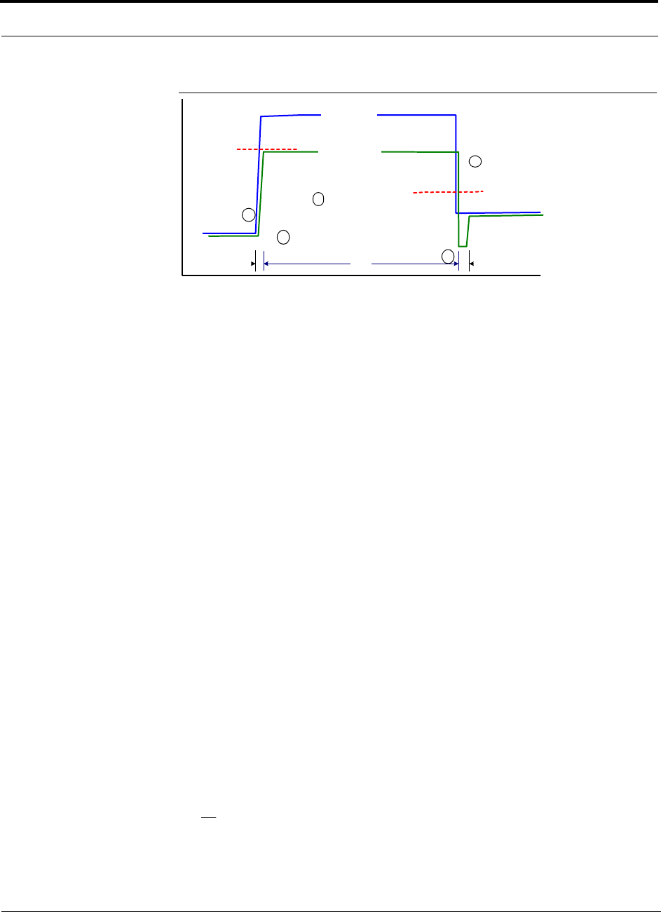
Connecting a Main Hub to a Base Station
6-40 InterReach Fusion Installation, Operation, and Reference Manual
CONFIDENTIAL
D-620610-0-20 Rev A
Figure 6-2
ALC Operation
6.8.2.1 Using the RAU 10 dB Attenuation Setting
Each RAU band can, independently of the other RAUs in a system, have its uplink or
downlink gain attenuated by 10dB in 1dB steps for each RAU band (1, 2, or 3). This
is accomplished by selecting the appropriate UPLINK and/or DOWNLINK attenua-
tion for each RAU band in the Edit Unit Properties screen of AdminBrowser for the
selected RAU.
•Downlink Attenuation: The downlink attenuator provides a mechanism to reduce
the signal strength from an RAU band. For instance, this could be for an RAU
band located near a window in a tall building that is causing excessive leakage to
the macro-network. In such a case it is important to attenuate the downlink only.
The uplink should not be attenuated. If the uplink is attenuated, the uplink sensitiv-
ity is reduced and mobile phones in the area of that RAU band will have to trans-
mit at a higher power. This would increase interference to the outdoor network
from such mobiles.
•Uplink Attenuation: The uplink attenuator attenuates environmental noise picked
up by an RAU band located in an area where heavy electrical machinery is operat-
ing. In such environments the electrical noise can be quite high and it is useful to
reduce the amount of such noise that gets propagated through the distributed
antenna system. Attenuating the uplink of an RAU band located in areas of high
electrical noise helps preserve the sensitivity of the rest of the system.
The effect of activating the uplink or downlink attenuators is to reduce the coverage
area of the adjusted RAU band. The coverage radius will be reduced by roughly a fac-
tor of 2. More specifically, if d is the coverage distance without attenuation and d’ is
the coverage radius with the attenuation, then
where PLS is path loss slope (dBm).
Input Signal
Level
Activation
Level
-30dBm
Release
Level
-45dBm
Output Signal
Level
Time
Hold
Phase
Release
Phase
Attack
Phase
1
2
3
4
5
PLSdB
d
d
/10
10
'
=

Help Hot Line (U.S. only): 1-800-530-9960 6-41
D-620610-0-20 Rev A
CONFIDENTIAL
Connecting a Main Hub to a Base Station
6.8.2.2 Using the Uplink ALC Setting
Uplink automatic level control (UL ALC) circuitry for each band within the RAU
provides automatic level control on high-power signals in the uplink path. This func-
tionality is required to prevent RF signal compression caused by a single or multiple
wireless devices in very close proximity to the RAU band. Compression causes signal
degradation and, ultimately, dropped calls and data errors, and should be prevented.
Two settings are available to optimize UL ALC performance:
•Multiple Operators: Use when more than one operator and/or protocol is present
in the Fusion system’s band frequency or adjacent frequency bands. This setting is
most commonly used.
•Single Operator and Protocol: Use when only one operator and protocol is
on-the-air within the Fusion system’s configured and adjacent frequency bands.
This setting is seldom used.

Connecting a Main Hub to a Base Station
6-42 InterReach Fusion Installation, Operation, and Reference Manual
CONFIDENTIAL
D-620610-0-20 Rev A