ADC Telecommunications FSN-809019-2 InterReach Fusion FSN-809019-2 User Manual fusionBOOK
ADC Telecommunications Inc. InterReach Fusion FSN-809019-2 fusionBOOK
Contents
- 1. User Manual Part One
- 2. User Manual Part Two
User Manual Part Two

InterReach Fusion Installation, Operation, and Reference Manual 7-1
D-620610-0-20 Rev A
CONFIDENTIAL
SECTION 7
Installing Fusion
This section contains the following subsections:
• Section 7.1 Installation Requirements . . . . . . . . . . . . . . . . . . . . . . . . . . . . . . . 7-1
• Section 7.2 Safety Precautions . . . . . . . . . . . . . . . . . . . . . . . . . . . . . . . . . . . . 7-3
• Section 7.3 Preparing for System Installation . . . . . . . . . . . . . . . . . . . . . . . . . 7-6
• Section 7.4 Fusion Installation Procedures . . . . . . . . . . . . . . . . . . . . . . . . . . 7-10
• Section 7.5 Splicing Fiber Optic Cable . . . . . . . . . . . . . . . . . . . . . . . . . . . . . 7-37
• Section 7.6 Interfacing the Fusion Main Hub to an RF Source . . . . . . . . . . 7-39
• Section 7.7 Connecting Contact Alarms to a Fusion System . . . . . . . . . . . . 7-49
• Section 7.8 Alarm Monitoring Connectivity Options . . . . . . . . . . . . . . . . . . 7-57
7.1 Installation Requirements
Before and during installation, keep in mind these sources of potential problems:
• Faulty cabling/connector
• Dirty connectors and ports
• Malfunction of one or more Fusion components
• Antenna, base station, or repeater problem
• External RF interface
• Tripped circuit breaker
• Equipment is not grounded
• Using a crossover Ethernet cable that does not support full hardware handshaking
when using AdminBrowser

Installation Requirements
7-2 InterReach Fusion Installation, Operation, and Reference Manual
CONFIDENTIAL
D-620610-0-20 Rev A
NOTE: Faulty cabling is the cause of a vast majority of problems. All CATV cable
should be tested to TIA-570-B specifications.
7.1.1 Component Location Requirements
Fusion components are intended to be installed in indoor locations only.
If outdoor installation is desired, such as a parking garage, the Fusion components
must be installed in the appropriate environmental enclosures.
7.1.2 Cable and Connector Requirements
Fusion equipment operates over the following:
• CATV 75 Ohm cable with F connectors
• Single-mode fiber (SMF) or multi-mode (MMF) cable with SC/APC fiber connec-
tors throughout the fiber network, including fiber distribution panels
These cables are widely-used, industry standards for the cable TV industry. The regu-
lations and guidelines for Fusion cable installation are identical to those specified by
the TIA/EIA 568-B standard and the TIA/EIA/570-A standards.
LGC Wireless recommends solid copper center conductor, plenum-rated CATV cable
and connectors for conformity to building codes, standards, and to ensure stated per-
formance of maximum distance and RF specifications.
CommScope 2065V cable or equivalent is required for RG-59.
CommScope 2279V cable or equivalent is required for RG-6.
CommScope 2293K cable may also be used for RG-11.
NOTE: Refer to Appendix A for more information related to 75 Ohm
CATV.
LGC Wireless recommends connectors with fixed centerpins to ensure proper seating
and to eliminate oxidation, which occurs with bare center conductors. Recommended
connectors are as follows:
CANARE Connectors
• FP-C4F for commScope 2065V cable
• FP-C55A for CommScope 2279V cable
• FP-C71A for CommScope 2293K cable

Help Hot Line (U.S. only): 1-800-530-9960 7-3
D-620610-0-20 Rev A
CONFIDENTIAL
Safety Precautions
NOTE: The proper crimp tool and die must be matched by the connector
type.
7.1.3 Distance Requirements
Table 7-1 shows the distances between Fusion components and related equipment.
7.2 Safety Precautions
7.2.1 Installation Guidelines
Use the following guidelines when installing LGC Wireless equipment:
1.
Provide sufficient airflow and cooling to the equipment to prevent heat build-up
from exceeding the maximum ambient air temperature specification. Do not com-
promise the amount of airflow required for safe operation of the equipment.
2.
If you are removing the system, turn it off and remove the power cord first. There
are no user-serviceable parts inside the components.
Table 7-1
Distance Requirements
Equipment
Combination Cable Type Cable Length Additional Information
Repeater/BTS to
Fusion Main Hub
Coaxial; N male
connectors
3–6 m (10–20 ft) typical Limited by loss and noise.
Refer to your link budget
calculation.
10 m (33 ft) maximum Limited by CE Mark require-
ments.
Fusion Expansion
Hub to RAU
CATV 75 Ohm;
shielded F male con-
nectors
• Minimum: 10 meters (33 ft)
• Maximum:
150 meters (492 ft) for RG-59;
170 meters (558 ft) for RG-6;
275 meters (902 ft) for RG-11
Refer to Table 5-1 and Table 5-2.
Refer to “System Gain” on
page 6-11.
Main Hub to Expan-
sion Hub
Multi-mode fiber:
Single-mode fiber:
SC/APC male con-
nectors
500 m (1640 ft.) maximum
6 km (19,685 ft.) maximum
Limited by 3 dB optical
attenuation
RAU to passive
antenna
Coaxial; N male
connectors
1–3.5 m (3–12 ft) typical Limited by loss and noise.
Refer to your link budget
calculation.

Safety Precautions
7-4 InterReach Fusion Installation, Operation, and Reference Manual
CONFIDENTIAL
D-620610-0-20 Rev A
3.
The internal power supplies have internal fuses that are not user replaceable. Con-
sider the worst-case power consumption shown on the product labels when provi-
sioning the equipment’s AC power source and distribution.
4.
Verify that the Hub is grounded properly using the AC power cord third wire
ground.
NOTE: Be careful with the mechanical loading of the rack mounted hub.
Mount the equipment in the rack in such a way that a hazardous condition,
due to uneven mechanical loading, does not result,.
7.2.2 General Safety Precautions
The following precautions apply to LGC Wireless products:
• The units have no user-serviceable parts. Faulty or failed units are fully replaceable
through LGC Wireless. Please contact us at:
1-800-530-9960 (U.S. only)
+1-408-952-2400 (International)
• Although modeled after an Ethernet/LAN architecture and connectivity, the units
are not intended to connect to Ethernet data hubs, routers, cards, or other similar
data equipment.
• When you connect the fiber optic cable, take the same precaution as if installing
Ethernet network equipment. All optical fiber SC/APC connectors should be
cleaned according to the cable manufacturer’s instructions.
• When you connect a radiating antenna to an RAU, firmly hand-tighten the N con-
nector – DO NOT over-tighten the connector.
WARNING: To reduce the risk of fire or electric shock, do not
expose this equipment to rain or moisture. The components are
intended for indoor use only. Do not install the RAU outdoors. Do not
connect an RAU to an antenna that is located outdoors where it could
be subject to lightning strikes, power crosses, or wind.
• The Expansion Hub and RAU units are designed for intra-building cabling only.
Outdoor routing of any cabling to these units shall not exceed 140 feet.
NOTE: Outdoor cables farther than 140 feet must be installed with proper
lightning protection.

Help Hot Line (U.S. only): 1-800-530-9960 7-5
D-620610-0-20 Rev A
CONFIDENTIAL
Safety Precautions
7.2.3 Fiber Port Safety Precautions
The following are suggested safety precautions for working with fiber ports. For
information about system compliance with safety standards, refer to Appendix B.
WARNING: Observe the following warning about viewing fiber
ends in ports. Do not stare with unprotected eyes at the connector
ends of the fibers or the ports of the hubs. Invisible infrared radia-
tion is present at the front panel of the Main Hub and the Expansion
Hub. Do not remove the fiber port dust caps unless the port is going
to be used. Do not stare directly into a fiber port.
•Test fiber cables: When you test fiber optic cables, connect the optical power
source last and disconnect it first. Use Class 1 test equipment.
•Fiber ends: Cover any unconnected fiber ends with an approved cap. Do not use
tape.
•Broken fiber cables: Do not stare with unprotected eyes at any broken ends of the
fibers. Laser light emitted from fiber sources can cause eye injury. Avoid contact
with broken fibers; they are sharp and can pierce the skin. Report any broken fiber
cables and have them replaced.
•Cleaning: Be sure the connectors are clean and free of dust or oils. Use only
approved methods for cleaning optical fiber connectors.
•Modifications: Do not make any unauthorized modifications to this fiber optic
system or associated equipment.
•Live work: Live work is permitted because LGC Wireless equipment is a Class 1
hazard.
•Signs: No warning signs are required.
•Class 1 laser product: The system meets the criteria for a Class 1 laser product
per IEC 60825-1: 1993+A1:+A2:2001 and IEC106825-2.
Complies with 21 CFR 1040.10 and 1040.11 except for deviations pursuant to
Laser Notice No. 50, dated July 26, 2001.
The hazard level at all locations within the equipment is Hazard Level 1.
•CAUTION: Use of controls or adjustments or performance of procedures other
than those specified herein may result in hazardous radiation exposure.
This mark appears on the front panel of the
Main Hub and the Expansion Hub.
CLASS 1
LASER PRODUCT
CLASS 1
LASER PRODUCT

Preparing for System Installation
7-6 InterReach Fusion Installation, Operation, and Reference Manual
CONFIDENTIAL
D-620610-0-20 Rev A
7.3 Preparing for System Installation
7.3.1 Pre-Installation Inspection
Follow this procedure before installing Fusion equipment:
1.
Verify the number of packages received against the packing list.
2.
Check all packages for external damage; report any external damage to the ship-
ping carrier. If there is damage, a shipping agent should be present before you
unpack and inspect the contents because damage caused during transit is the
responsibility of the shipping agent.
3.
Open and check each package against the packing list. If any items are missing,
contact LGC Wireless customer service (refer to Section 7.2.2 on page 7-4).
4.
If damage is discovered at the time of installation, contact the shipping agent.
7.3.2 Installation Checklist
Table 7-2
Installation Checklist
Installation Requirement Consideration
Floor Plans Installation location of equipment clearly marked
System Design Used to verify frequency bands after installation
Power available:
Fusion Main Hub (AC)
Fusion Expansion Hub (AC)
To RAU (DC)
Hub’s power cord is 2 m (6.5 ft) long.
115/230V, 2/1A, 50–60 Hz
115/230V, 6/3A, 50-60 Hz
54V (from the Hub)
Rack space available
(Main and Expansion Hub)
89 mm (3.5 in.) high (2U)
Wallmount Fusion Main Hub Hub must be mounted on 3/4” plywood backboard.
Clearance for air circulation:
Fusion Main or Expansion Hub
RAU
76 mm (3 in.) front and rear, 51 mm (2 in.) sides
76 mm (3 in.) all around
Suitable operating environment:
Fusion Main or Expansion Hub
RAUs
Indoor location only
0° to +45°C (+32° to +113°F)
5% to 95% non-condensing humidity
–25° to +45°C (–13° to +113°F)
5% to 95% non-condensing humidity
Donor Antenna-to-Fusion Configuration (for each Fusion Band)
Donor Antenna Installed, inspected; N-male to N-male coaxial cable to lightning arrestor/surge
suppressor
Lightning Arrestor or
Surge Suppressor
Installed between roof-top antenna and repeater; N-male to N-male 50 Ohm coax-
ial cable and outdoor cables longer than 140 feet.
Repeater Installed between lightning arrestor/surge suppressor and Hub; N-male to N-male
coaxial cable. The Repeater must be a UL listed product.

Help Hot Line (U.S. only): 1-800-530-9960 7-7
D-620610-0-20 Rev A
CONFIDENTIAL
Preparing for System Installation
Attenuator Installed between the circulator and the Hub downlink port to prevent overload.
Optionally, it may be installed between the uplink port and the circulator.
Circulator or Duplexer Installed between the repeater and the Hub uplink and downlink ports
Base Station-to-Fusion Configuration (for each Fusion Band)
Base Station Installed, inspected; verify RF power (see tables in Section 6.3 on page 6-4);
N-male to N-male coaxial cable
Attenuator Attenuation may be required to achieve the desired RF output at the RAU, and the
desired uplink noise floor level
Circulator or Duplexer When using a duplex BTS: Installed between the BTS and the Hub uplink and
downlink ports. Not used with a simplex BTS
Connecting Multiple Fusion Main Hubs Together
5-port Alarm Daisy-Chain Cable
(PN 4024-3)
For contact alarm monitoring of fault and warning alarms. Used to feed the alarms
from multiple Fusion Main Hubs into a BTS or MetroReach Focus. N.C. Opera-
tion.
Cabling
Coaxial: repeater, base station,
Smart Source to Fusion Main
Hub
Coax approved; N-type male connectors.
Coaxial: RAU to passive
antennas
Use low-loss cable; N male connector; typical 1 m (3.3 ft) using RG142 coaxial
cable.
Fiber: Main Hub to Expansion
Hubs
SC/APC (angle-polished) male connectors for entire fiber run (can use SC/APC
pigtails, PN 4012SCAPC-10 for MMF or 4013SCAPC-10 for SMF);
Use jumper fiber cables for collocated Main and Expansion Hubs (3 m/10 ft.):
Multi-mode: PN 401SCAPC-10
Single-mode: PN 4018SCAPC-10
Distance limited by optical loss of 3 dB
Multi-mode up to 500 m (1640 ft.)
Single-mode up to 6 km (19,685 ft.)
CATV TIA-570-B approved; centerpin F male connectors. CATV cable must be screened
and it must be grounded at both connector ends. The RAU will be damaged if it is
mis-wired.
Tie-off cables to avoid damaging the connectors because of cable strain.
Fusion Expansion Hub to RAUs • Minimum: 0 meters (0 ft)
• Maximum: RG-59: 150 meters (472 ft) *
RG-8: 170 meters (558 ft)
RG-11: 275 meters (902 ft)
* Refer to Appendix A for CATV cable requirements.
Table 7-2
Installation Checklist (continued)
Installation Requirement Consideration

Preparing for System Installation
7-8 InterReach Fusion Installation, Operation, and Reference Manual
CONFIDENTIAL
D-620610-0-20 Rev A
7.3.3 Tools and Materials Required
Configuring the System
PC/laptop running
standard browser software
Refer to the AdminBrowser User Manual (PN D-620607-0020)
Miscellaneous
Cross-over Ethernet cable Male connectors; Fusion Main Hub to a PC/laptop running a standard browser to
the Fusion AdminBrowser software; local connection or LAN switch connector
for remote connections.
Straight-through cable Female/male connectors; Fusion Main Hub to a modem for a remote connection.
Distances
Fusion Main Hub is within 3–6m
(10–20 ft) of connecting
repeater/BTS/MetroReach
If longer distance, determine the loss of the cable used for this connection and
adjust the RF signal for each Band into the Fusion Main Hub accordingly. This can
be done by readjusting the power from the base station, or by changing the attenu-
ation value between the base station/repeater and the Hub Bands (1 and 2).
Table 7-3
Tools and Materials Required for Component Installation
Description
Cable ties
Screwdriver
Mounting screws and spring nuts
Screws, anchors (for mounting RAUs)
Drill
Fiber connector cleaning kit
Fusion splicer
Splicing tool kit (including snips, cladding strippers, fiber cleaver, isopropyl alcohol,
lint-free wipes)
Fusion splicing sleeves
Table 7-2
Installation Checklist (continued)
Installation Requirement Consideration

Help Hot Line (U.S. only): 1-800-530-9960 7-9
D-620610-0-20 Rev A
CONFIDENTIAL
Preparing for System Installation
7.3.4 Optional Accessories
Table 7-4
Optional Accessories for Component Installation
Description
Wall-mount bracket (PN 4712)
When using this bracket with an Fusion Main Hub, the Hub’s mounting bracket must
be moved to the alternate mounting position (refer to the procedure on page
page 7-11).
Cable management (Cable manager: PN 4759; Tie wrap bar: PN 4757)
Splice trays
Pigtails with SC/APC connectors, 3 m (10 ft.)
Multi-mode fiber SC/APC pigtail: PN 402SCAPC-10
Single-mode fiber SC/APC pigtail: PN 4013SCAPC-10
Jumper cable when Main and Expansion Hubs are collocated, 3 m (10 ft.)
Multi-mode fiber SC/APC: PN 4018SCAPC-10
Teltone Line Sharing Switch (M-394-B-01)
When using a single POTS line with multiple Fusion Main Hub/Modems: Connect up
to four modems to a line sharing switch; switches can be cascaded to accommodate up
to 16 modems per POTS line
Alarm Cables:
5-port Alarm Daisy-Chain Cable (PN 4024-3)
Alarm Sense Adapter Cable (PN 4025-1)

Fusion Installation Procedures
7-10 InterReach Fusion Installation, Operation, and Reference Manual
CONFIDENTIAL
D-620610-0-20 Rev A
7.4 Fusion Installation Procedures
The following procedures assume that the system is new from the factory and that it
has not been programmed with bands.
If you are replacing components in a pre-installed system with either new units or
units that may already be programmed (for example, re-using units from another sys-
tem), refer to Section 8.
• Installing a Fusion Main Hub . . . . . . . . . . . . . . . . . . . . . . . . . . . . . . . . . . . . . . 7-11
• Installing a Fusion Main Hub in a Rack . . . . . . . . . . . . . . . . . . . . . . . . . . . 7-11
• Using the Wall Rack-Mounting Option . . . . . . . . . . . . . . . . . . . . . . . . . . . 7-13
• Installing an Optional Cable Manager in the Rack . . . . . . . . . . . . . . . . . . 7-12
• Installing a Main Hub Using the 12” Wall-Mounted Rack (PN 4712) . . . 7-12
• Installing a Fusion Main Hub Directly to the Wall . . . . . . . . . . . . . . . . . . 7-14
• Connecting the Fiber Cables to the Main Hub . . . . . . . . . . . . . . . . . . . . . . 7-15
• Powering On the Main Hub . . . . . . . . . . . . . . . . . . . . . . . . . . . . . . . . . . . . 7-18
• Installing Expansion Hubs . . . . . . . . . . . . . . . . . . . . . . . . . . . . . . . . . . . . . . . . 7-20
• Installing an Expansion Hub in a Rack . . . . . . . . . . . . . . . . . . . . . . . . . . . 7-20
• Installing an Expansion Hub Using the 12” Wall-Mounted Rack . . . . . . . 7-21
• Installing a Fusion Expansion Hub Directly to the Wall . . . . . . . . . . . . . . 7-22
• Installing an Optional Cable Manager in the Rack . . . . . . . . . . . . . . . . . . 7-23
• Powering On the Expansion Hub . . . . . . . . . . . . . . . . . . . . . . . . . . . . . . . . 7-23
• Connecting the Fiber Cables to the Expansion Hub . . . . . . . . . . . . . . . . . . 7-24
• Connecting the 75 Ohm CATV Cables . . . . . . . . . . . . . . . . . . . . . . . . . . . 7-25
• Troubleshooting Expansion Hub LEDs During Installation . . . . . . . . . . . 7-26
• Installing RAUs . . . . . . . . . . . . . . . . . . . . . . . . . . . . . . . . . . . . . . . . . . . . . . . . 7-27
• Installing RAUs . . . . . . . . . . . . . . . . . . . . . . . . . . . . . . . . . . . . . . . . . . . . . 7-27
• Installing Passive Antennas . . . . . . . . . . . . . . . . . . . . . . . . . . . . . . . . . . . . 7-27
• Connecting the Antenna to the RAU . . . . . . . . . . . . . . . . . . . . . . . . . . . . . 7-29
• Connecting the CATV Cable . . . . . . . . . . . . . . . . . . . . . . . . . . . . . . . . . . . 7-29
• Troubleshooting Using RAU LEDs During Installation . . . . . . . . . . . . . . 7-30
• Installing RAUs in a Multiple Operator System . . . . . . . . . . . . . . . . . . . . 7-31
• Configuring the System . . . . . . . . . . . . . . . . . . . . . . . . . . . . . . . . . . . . . . . . . . 7-31
• Connecting the PC to the Fusion Main Hub to Run AdminBrowser . . . . . 7-31
• Programming the Fusion Main Hub Using AdminBrowser . . . . . . . . . . . . 7-32
• Fusion Splicing of Fiber and Pigtail . . . . . . . . . . . . . . . . . . . . . . . . . . . . . . . . . 7-37
Help Hot Line (U.S. only): 1-800-530-9960 7-11
D-620610-0-20 Rev A
CONFIDENTIAL
Fusion Installation Procedures
The following procedures assume that the system is installed and programmed.
• Interfacing the Fusion Main Hub to an RF Source . . . . . . . . . . . . . . . . . . . . . 7-39
• Connecting a Single Fusion Main Hub to an RF Source . . . . . . . . . . . . . . 7-39
• Connecting a Fusion Main Hub to a Roof-top Antenna . . . . . . . . . . . . . . . 7-43
• Connecting Multiple Fusion Main Hubs to an RF Source . . . . . . . . . . . . . 7-44
• Connecting Multiple Fusion Main Hubs to a Duplex Repeater or BTS . . 7-47
• Connecting Contact Alarms to a Fusion System . . . . . . . . . . . . . . . . . . . . . . . 7-49
• Alarm Source . . . . . . . . . . . . . . . . . . . . . . . . . . . . . . . . . . . . . . . . . . . . . . . 7-50
• Alarm Sense . . . . . . . . . . . . . . . . . . . . . . . . . . . . . . . . . . . . . . . . . . . . . . . . 7-53
• Alarm Cables . . . . . . . . . . . . . . . . . . . . . . . . . . . . . . . . . . . . . . . . . . . . . . . 7-55
• Alarm Monitoring Connectivity Options . . . . . . . . . . . . . . . . . . . . . . . . . . . . . 7-57
• Direct Connection . . . . . . . . . . . . . . . . . . . . . . . . . . . . . . . . . . . . . . . . . . . . 7-57
• Modem Connection . . . . . . . . . . . . . . . . . . . . . . . . . . . . . . . . . . . . . . . . . . 7-58
• 100 BASE-T Port Expander Connection . . . . . . . . . . . . . . . . . . . . . . . . . . 7-67
• POTS Line Sharing Switch Connection . . . . . . . . . . . . . . . . . . . . . . . . . . . 7-68
• Ethernet LAN Connection . . . . . . . . . . . . . . . . . . . . . . . . . . . . . . . . . . . . . 7-70
• SNMP Interface . . . . . . . . . . . . . . . . . . . . . . . . . . . . . . . . . . . . . . . . . . . . . 7-71
7.4.1 Installing a Fusion Main Hub
CAUTION: Install Fusion Main Hubs in indoor locations only.
Installing a Fusion Main Hub in a Rack
The Fusion Main Hub (2U high) mounts in a standard 19 in. (483 mm) equipment
rack. Allow clearance of 76 mm (3 in.) front and rear, and 51 mm (2 in.) on both sides
for air circulation. No top or bottom clearance is required.
Fusion Installation Procedures
7-12 InterReach Fusion Installation, Operation, and Reference Manual
CONFIDENTIAL
D-620610-0-20 Rev A
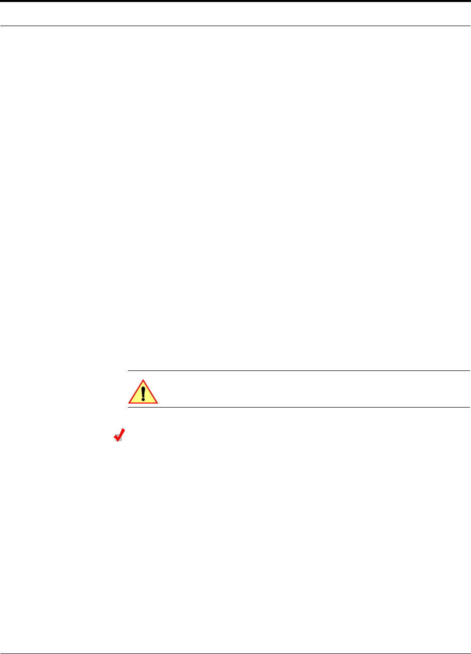
Figure 7-1
Flush Mounting Bracket Detail
Consideration:
• The Fusion Main Hub is shipped with #10-32 mounting screws. Another common
rack thread is #12-24. Confirm that the mounting screws match the rack’s threads.
To install the Hub in a rack:
1.
Insert spring nuts into rack where needed or use existing threaded holes.
2.
Place the Hub into the rack from the front.
3.
Align the flange holes with the spring nuts installed in Step 1.
4.
Insert the mounting screws in the appropriate positions in the rack.
5.
Tighten the mounting screws.
Installing an Optional Cable Manager in the Rack
• Using the screws provided, fasten the cable manager to the rack, immediately
above or below the Main Hub.
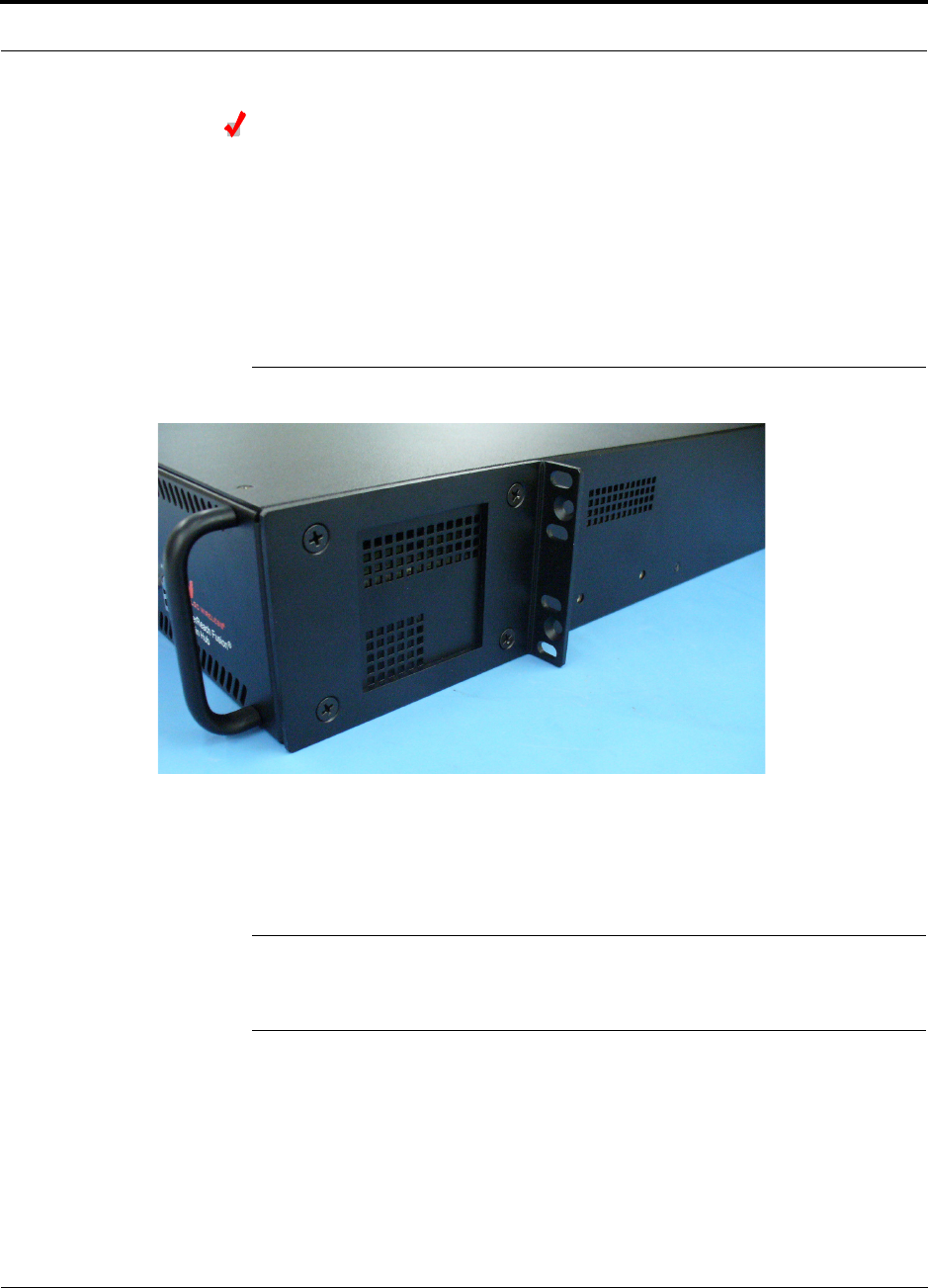
Installing a Main Hub Using the 12” Wall-Mounted Rack (PN 4712)
Considerations:
• The rack-mounting brackets on the Fusion Main Hub must be moved to the
recessed mounting position (shown in Figure 7-2) to allow for the required 76 mm
(3 in.) rear clearance.
Help Hot Line (U.S. only): 1-800-530-9960 7-13
D-620610-0-20 Rev A
CONFIDENTIAL
Fusion Installation Procedures
• The maximum weight the bracket can hold is 22.5 kg (50 lbs).
• The bracket is designed to accommodate a Fusion Main Hub (12 lbs.) or an Expan-
sion Hub (14.5 lbs.).
• The wall mount bracket should be securely mounted to wall, using the four key slot
mounting holes on the bracket.
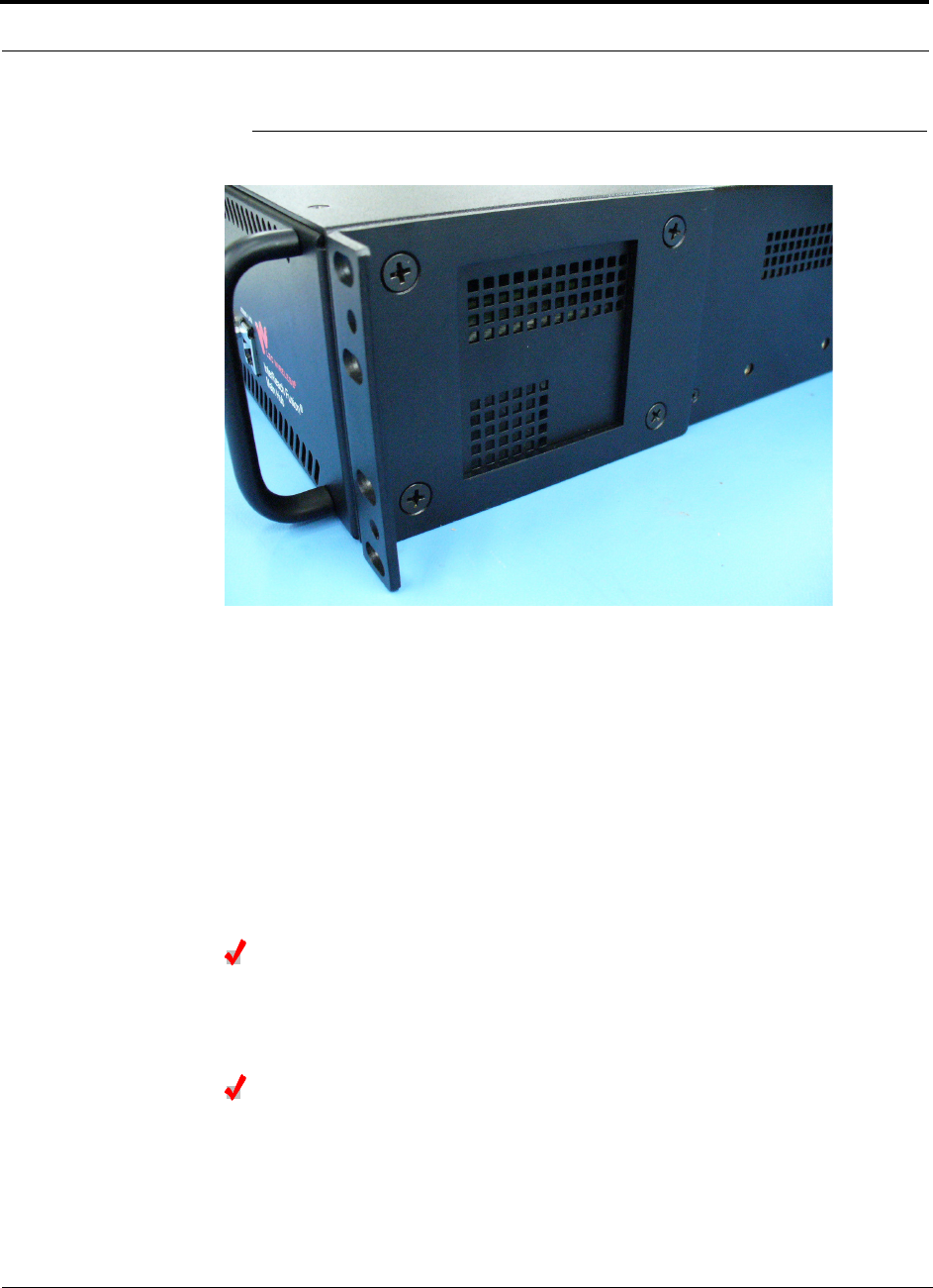
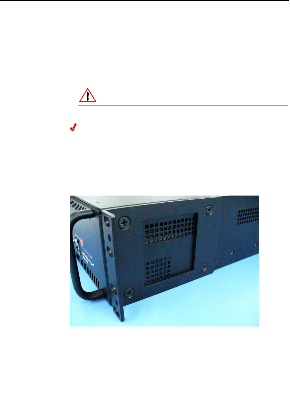
Using the Wall Rack-Mounting Option
You can flip the rack mounting brackets, as shown in Figure 7-2, so the hub can be
mounted 76 mm (3 in.) forward in the rack.
Figure 7-2
Bracket Detail For Wall Mount Rack (PN 4712)
To install the Hub to the wall-mounted rack:
1.
Attach the wall bracket (PN 4712) to wall the using #10 Pan Head wood screws,
1-1/2” minimum length for mounting in wood studs or 3/4“thick plywood.
The bracket must be positioned so that the Hub will be in a horizontal position
when it is installed. (Refer to Figure 7-2.)
NOTE: If wall stud spacing of 16” is not available, LGC recommends that
3/4” plywood be pre-installed to the wall. You can then attach the bracket to
the plywood using the wood screws.
2.
Remove both of the rack mounting brackets from the Hub.
3.
Reattach each of the rack mounting brackets to the recessed wall mount position.
4.
Install the Hub in the rack using the rack mounting screws.
Fusion Installation Procedures
7-14 InterReach Fusion Installation, Operation, and Reference Manual
CONFIDENTIAL
D-620610-0-20 Rev A
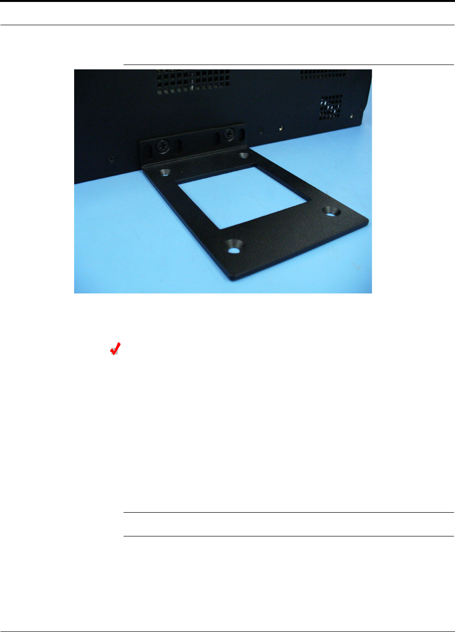
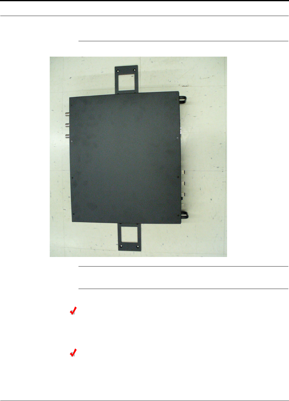
Installing a Fusion Main Hub Directly to the Wall
To install the Hub directly to the wall:
1.
Pre-install 3/4” plywood to the wall.
2.
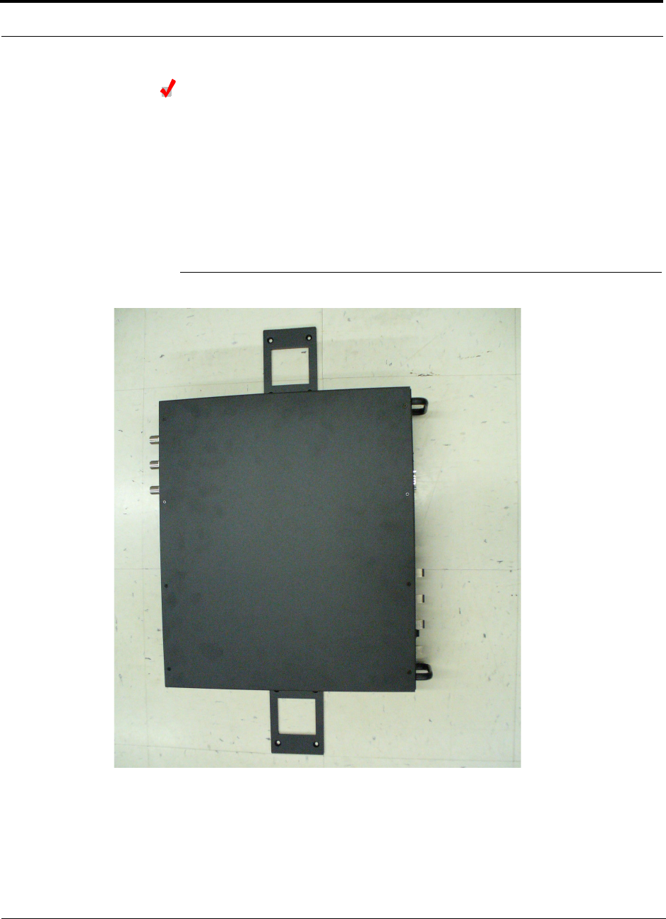
Mount both of the rack mounting brackets using #10-32 machine screws (refer to
illustration Figure 7-4).
3.
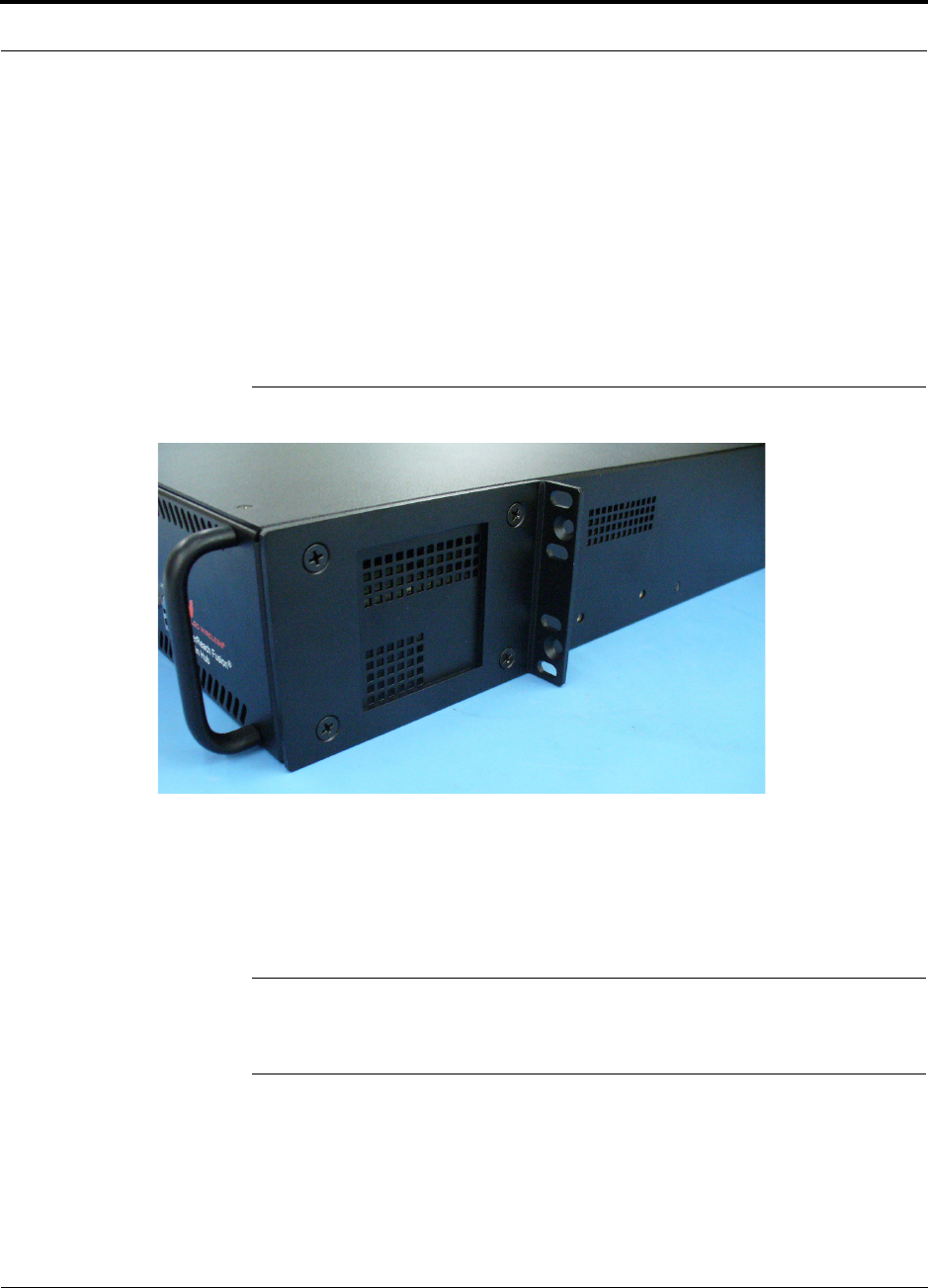
Attach the Hub to the wall so the mounting brackets are orientated at the top and
bottom of the wall mounted hub. (Refer to Figure 7-3.)
Figure 7-3
Installing Directly to the Wall
Use two #10 Pan Head wood screws, 1-1/2” length, to secure each bracket to the
plywood. In this orientation the enclosure fans shall face to the left.
Help Hot Line (U.S. only): 1-800-530-9960 7-15
D-620610-0-20 Rev A
CONFIDENTIAL
Fusion Installation Procedures
Figure 7-4
Using Hub Rack-Mounting Brackets for Direct Wall Installation
Connecting the Fiber Cables to the Main Hub
Considerations:
• Before connecting the fiber cables, confirm that their optical loss does not exceed
the 3 dB optical budget.
• If you are using fiber distribution panels, confirm that the total optical loss of fiber
cable, from the Main Hub through distribution panels and patch cords to the
Expansion Hub, does not exceed the optical budget.
• Make sure the fiber cable’s connectors are SC/APC (angle-polished). Using any
other connector type will result in degraded system performance and may damage
the equipment. (You can use an SC/APC pigtail if the fiber cable’s connectors are
not SC/APC. Refer to“Fusion Splicing of Fiber and Pigtail” on page 7-37. Or, you
can change the fiber’s connector to SC/APC.)
NOTE: Observe all Fiber Port Safety Precautions listed in Section 7.2.3 on page 7-5.

Fusion Installation Procedures
7-16 InterReach Fusion Installation, Operation, and Reference Manual
CONFIDENTIAL
D-620610-0-20 Rev A
To clean the fiber ports:
You can clean the Hub’s fiber ports using canned compressed air or isopropyl alcohol
and foam tipped swabs.
Considerations:
• If using compressed air:
• The air must be free of dust, water, and oil.
• Hold the can level during use.
• If using isopropyl alcohol and foam tipped swabs:
• Use only 98% pure or more alcohol
Procedure using compressed air:
1.
Remove the port’s dust cap.
2.
Spray the compressed air away from the unit for a few seconds to clean out the
nozzle and then blow dust particles out of each fiber port.
Procedure using isopropyl alcohol:
1.
Remove the connector’s dust cap.
2.
Dip a 2.5mm lint-free, foam-tipped swab in isopropyl alcohol and slowly insert
the tip into the connector.
3.
Gently twist the swab to clean the port.
4.
Insert a dry swab into the port to dry it.
Additionally, you can use compressed air after the alcohol has completely evapo-
rated.
To clean the fiber ends:
Be sure that the fiber cable’s SC/APC connectors are clean and free of dust and oils.
You need lint-free cloths, isopropyl alcohol, and compressed air
1.
Moisten a lint-free cloth with isopropyl alcohol.
2.
Gently wipe the fiber end with the moistened cloth.
3.
Using a dry lint-free cloth, gently wipe the fiber end.
4.
Spray the compressed air away from the connector for a few seconds to clean out
the nozzle and then use it to completely dry the connector.
To test the fiber cables:
Perform cable testing and record the results. Test results are required for the final
As-Built Document.
To connect the fiber cables:
The fiber cable is labeled with either
1
or
2
, or is color-coded. In addition to these
labels, you should add a code that identifies which port on the Main Hub is being

Help Hot Line (U.S. only): 1-800-530-9960 7-17
D-620610-0-20 Rev A
CONFIDENTIAL
Fusion Installation Procedures
used and which Expansion Hub the cables are intended for. This differentiates the
connectors for proper connection between the Main Hub and Expansion Hubs.
For example:
First pair to Main Hub port 1: 11 (uplink), 12 (downlink);
Second pair to Main Hub port 2: 21 (uplink), 22 (downlink);
Third pair to Main Hub port 3: 31 (uplink), 32 (downlink); and so on.
If the fiber jumper is labeled with
1
or
2
:
1.
Connect
1
s to
UPLINK
ports on the Main Hub.
2.
Connect
2
s to
DOWNLINK
ports on the Main Hub.
3.
Record which cable number and port number you connected to
UPLINK
and
DOWNLINK
.
This information is needed when connecting the other end of the fiber cable to the
Expansion Hub’s fiber ports.
The fiber port LEDs should be off, indicating that the Expansion Hub(s) are not
connected.
If the fiber jumper is color-coded (for example, “blue” or “red”):
1.
Connect “blue” to
UPLINK
ports on the Main Hub.
2.
Connect “red” to
DOWNLINK
ports on the Main Hub.
3.
Record which color and port number you connected to
UPLINK
and
DOWNLINK
.
This information is needed when connecting the other end of the fiber cable to the
Expansion Hub’s fiber ports.
The fiber port LEDs should be off, indicating that the Expansion Hub(s) are not
connected.

Fusion Installation Procedures
7-18 InterReach Fusion Installation, Operation, and Reference Manual
CONFIDENTIAL
D-620610-0-20 Rev A
Powering On the Main Hub
1.
Connect the AC power cord to the Main Hub.
2.
Plug the power cord into an AC power outlet.
3.
Turn on the power to the Main Hub and check that all the LED lamps are func-
tioning properly.
Upon power-up, the LEDs blinks for five seconds as a visual check that they are
functioning. After the five-second test:
LED states during power on will vary, depending on whether Expansion Hubs are
connected. Refer to Table 7-5 for possible combinations.
Table 7-5
Troubleshooting Main Hub LEDs During Installation
During
Installation
Power On LED State Action Impact
1.
Main Hub
power is
On with no
Expansion
Hubs con-
nected.
POWER
Off Check AC power; check that the Main Hub power-on
switch is on; replace the Main Hub
The Main Hub is not
powering on.
POWER
Red Replace the Main Hub The power supply is
out-of-specification.
PORT
LEDs are on
but they
didn’t blink
through all
states
Replace the Main Hub. The micro controller is
not resetting properly;
flash memory cor-
rupted.
PORT
Red The port is unusable; replace the Main Hub when
possible.
Fiber sensor fault, do
not use the port.
Off

Help Hot Line (U.S. only): 1-800-530-9960 7-19
D-620610-0-20 Rev A
CONFIDENTIAL
Fusion Installation Procedures
2.
Main Hub
power is
On with
Expansion
Hubs con-
nected and
powered
on.
PORT
Off • If the port LEDs do not illuminate, check the fiber
uplink for excessive optical loss.
• If Expansion Hub’s
DL STATUS
LED is red:
• Verify that the fiber is connected to the correct
port (that is, uplink/downlink)
• Swap the uplink and downlink cables.
• Connect the fiber pair to another port. If the sec-
ond port’s LEDs do not illuminate Green/Red,
replace the Main Hub.
• If the second port works, flag the first port as
unusable; replace the Main Hub when possible.
No uplink optical
power, the Expansion
Hub is not recognized
as being present.
No communication
with the Expansion
Hub.
PORT
Red (60 ppm) • If the Expansion Hub
DL STATUS
LED is red,
check the downlink fiber cable for excessive opti-
cal loss.
• Connect the fiber pair to another port. If the sec-
ond port’s LEDs do not illuminate Green/Red,
replace the Main Hub.
• If the second port works, flag the first port as
unusable; replace the Main Hub when possible.
No communication
with the Expansion
Hub.
PORT
Red The Expansion Hub or connected RAU reports a fault
Use AdminManager to determine the problem.
The Expansion Hub or
one or more RAUs are
off-line.
Table 7-5
Troubleshooting Main Hub LEDs During Installation (continued)
During
Installation
Power On LED State Action Impact
Fusion Installation Procedures
7-20 InterReach Fusion Installation, Operation, and Reference Manual
CONFIDENTIAL
D-620610-0-20 Rev A
7.4.2 Installing Expansion Hubs
The Expansion Hub (2U high) can be installed in a standard 19 in. (483 mm) equip-
ment rack or in a wall-mountable equipment rack that is available from LGC Wire-
less. Allow a clearance of 76 mm (3 in.) front and rear and 51 mm (2 in.) sides for air
circulation. No top and bottom clearance is required.
CAUTION: Install Expansion Hubs in indoor locations only.
Installing an Expansion Hub in a Rack
Consideration:
• The Expansion Hub is shipped with #10-32 mounting screws. Another common
rack thread is #12-24. Confirm that the mounting screws match the rack’s threads.
Figure 7-5
Flush Mounting Bracket Detail
To install the hub in a rack:
1.
Insert spring nuts into the rack where needed or use existing threaded holes.
2.
Place the Expansion Hub into the rack from the front.
3.
Align the flange holes with the spring nuts installed in Step 1.
4.
Insert the mounting screws in the appropriate positions in the rack.
5.
Tighten the mounting screws.
Help Hot Line (U.S. only): 1-800-530-9960 7-21
D-620610-0-20 Rev A
CONFIDENTIAL
Fusion Installation Procedures
Installing an Expansion Hub Using the 12” Wall-Mounted Rack
Considerations:
• The rack (PN4712) is 305 mm (12 in.) deep. The Expansion Hub is 381 mm (15
in.) deep. You must move the rack mounting brackets on the Expansion Hub, as
shown in Figure 7-6) to the center mounting position to allow for the 76 mm (3 in.)
rear clearance that is required.
• The maximum weight the rack can hold is 22.5 kg (50 lbs).
Figure 7-6
Bracket Detail For Wall Mount Rack (PN 4712)
To install the hub in a wall-mounted rack:
1.
Attach the equipment rack to the wall using the screws that are provided.
The rack must be positioned so that the Expansion Hub will be in a horizontal
position when it is installed.
NOTE: If wall stud spacing of 16” is not available, LGC recommends that
3/4” plywood be pre-installed to the wall. You can then attach the bracket to
the plywood using the wood screws.
2.
Remove both of the rack mounting brackets from the Hub.
3.
Reattach each of the rack mounting brackets to the recessed wall mount position
(Figure 7-6).
4.
Install the Hub in the rack using the rack mounting screws.
5.
Tighten the mounting screws.
Fusion Installation Procedures
7-22 InterReach Fusion Installation, Operation, and Reference Manual
CONFIDENTIAL
D-620610-0-20 Rev A
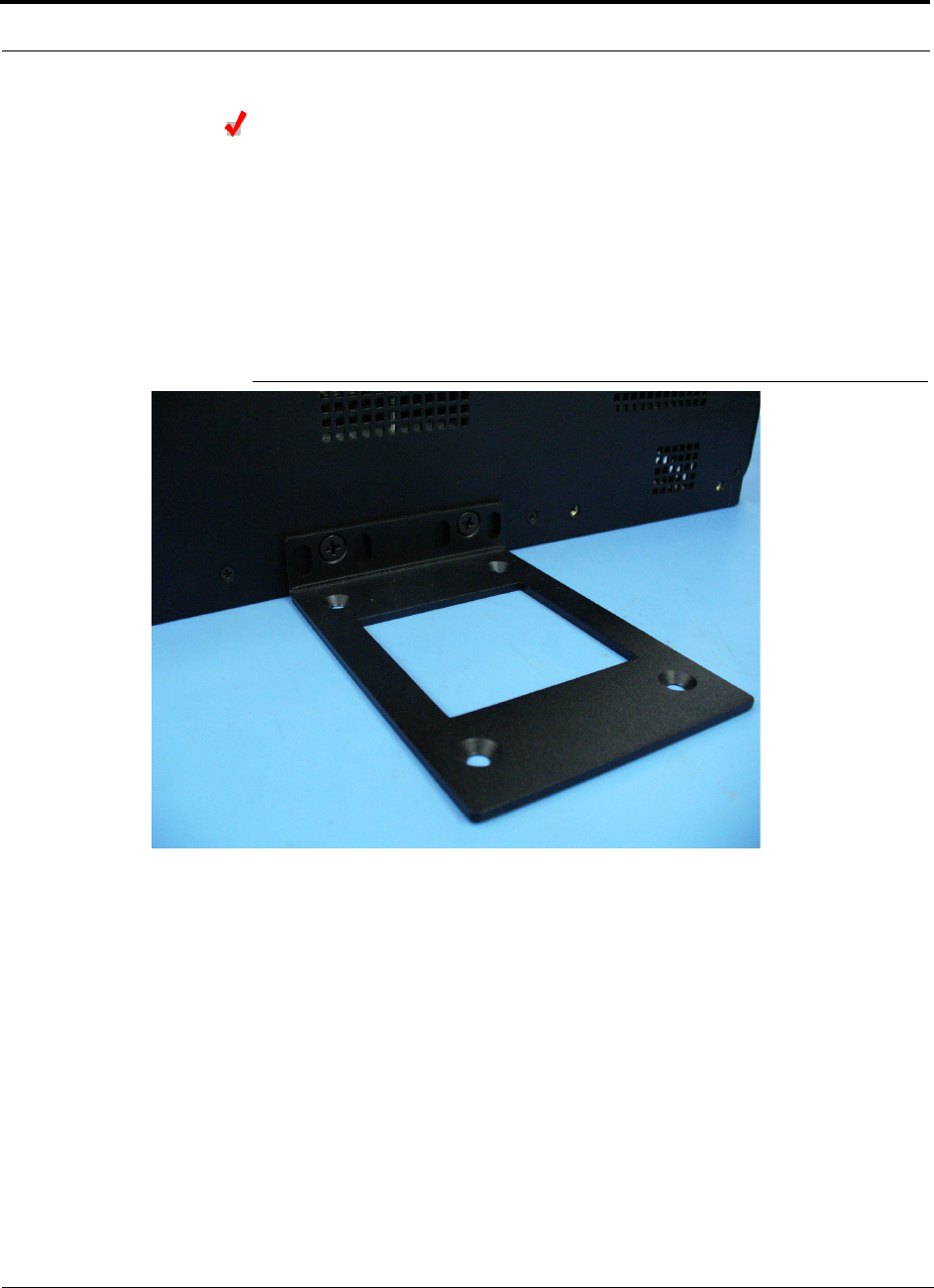
Installing a Fusion Expansion Hub Directly to the Wall
To install the Hub directly to the wall:
1.
Pre-install 3/4” plywood to the wall.
2.
Mount both of the rack mounting brackets using #10-32 machine screws (refer to
illustration Figure 7-7).
3.
Attach the Hub to the wall so the mounting brackets are orientated at the top and
bottom of the wall mounted hub. (Refer to Figure 7-8.)
Figure 7-7
Using Hub Rack-Mounting Brackets for Direct Wall Installation
Help Hot Line (U.S. only): 1-800-530-9960 7-23
D-620610-0-20 Rev A
CONFIDENTIAL
Fusion Installation Procedures
Figure 7-8
Installing Directly to the Wall
NOTE: Leave the dust caps on the fiber ports until you are ready to connect the fiber
optic cables.
Installing an Optional Cable Manager in the Rack
• Using the screws provided, fasten the cable manager to the rack, immediately
above or below the Expansion Hub.
Powering On the Expansion Hub
1.
Connect the AC power cord to the Expansion Hub.
2.
Plug the power cord into an AC power outlet.

Fusion Installation Procedures
7-24 InterReach Fusion Installation, Operation, and Reference Manual
CONFIDENTIAL
D-620610-0-20 Rev A
3.
Turn on the power to the Expansion Hub and check that all the LED lamps are
functioning properly.
Upon power-up, the LEDs blinks for five seconds as a visual check that they are
functioning. After the five-second test:
• The
POWER
and
UL STATUS
LEDs should be green.
– If the uplink fiber is not connected, the
UL STATUS
LED turns red indicating
that there is no communication with the Main Hub.
• The
E-HUB STATUS
and
DL STATUS
LEDs should be red.
• All port LEDs should be off because no RAUs are connected yet.
Connecting the Fiber Cables to the Expansion Hub
Considerations:
• Before connecting the fiber cables, confirm that their optical loss does not exceed
3 dB optical budget. RL is less than -60dB.
• If fiber distribution panels are used, confirm that the total optical loss of fiber
cable, from the Main Hub through distribution panels and patch cords to the
Expansion Hub, does not exceed the optical budget.
• Make sure the fiber cable’s connectors are SC/APC (angle-polished).Using any
other connector type will result in degraded system performance and may damage
the equipment. (You can use an SC/APC pigtail if the fiber cable’s connectors are
not SC/APC, refer to “Fusion Splicing of Fiber and Pigtail” on page 7-37, or
replace the connectors.)
NOTE: Observe all Fiber Port Safety Precautions listed in Section 7.2.3 on page 7-5.
To connect the fiber cables:
The fiber cable is labeled with either
1
or
2
, or is color-coded. For proper connection
between the Main Hub ports and the Expansion Hub ports, refer to the numbering or
color-coded connections you recorded when installing the Main Hub(s).
If the fiber jumper is labeled with
1
or
2
:
1.
Connect
2
to
DOWNLINK
on Expansion Hub.
The
DL STATUS
LED should turn green as soon as you connect the fiber. If it does
not, there is a downlink problem. Make sure you are connecting the correct cable
to the port.
2.
Connect
1
to
UPLINK
on Expansion Hub.
The
UL STATUS
LED turns green on the first Main Hub communication. It may
take up to 20 seconds to establish communication.
The Expansion Hub’s
E-HUB STATUS
LED turns green when the Main Hub sends
it the frequency band command.

Help Hot Line (U.S. only): 1-800-530-9960 7-25
D-620610-0-20 Rev A
CONFIDENTIAL
Fusion Installation Procedures
If the
UL STATUS
and
E-HUB STATUS
LEDs do not turn green/green, check the
Main Hub LEDs. Refer to page 7-18, item 2 in Table 7-5.
If the fiber jumper is color-coded (for example, “blue” or “red”):
1.
Connect “red” to
DOWNLINK
on Expansion Hub.
The
DL STATUS
LED should turn green as soon as you connect the fiber. If it does
not, there is a downlink problem. Make sure you are connecting the correct cable
to the port.
2.
Connect “blue” to
UPLINK
on Expansion Hub.
The
UL STATUS
LED turns green on the first Main Hub communication. It may
take up to 20 seconds to establish communication.
The Expansion Hub’s
E-HUB STATUS
LED turns green when the Main Hub sends
it the frequency band command.
If the
UL STATUS
and
E-HUB STATUS
LEDs do not turn green/green, check the
Main Hub LEDs. See page 7-18, item 2 in Table 7-5.
Connecting the 75 Ohm CATV Cables
Considerations:
• Verify that the cable has been tested and the test results are recorded. This informa-
tion is required for the As-Built Document.
• Verify that only captive centerpin F connectors are used on the solid copper center
conductor CATV cable from CommScope (or equivalent).
• Verify that the CATV cable is labeled with:
• Fusion Expansion Hub port number being used
• RAU identifier
• Carrier (for multiple operator systems)
To connect the CATV cables:
1.
Connect the CATV cables to the F ports according to the labels on the cables.
The
STATUS
LEDs should be off because the RAUs are not connected at the other
end of the CATV cable.
2.
Record which cable you are connecting to which port (that is, from the label on
the cable).
This information is required for the As-Built Document.
3.
Tie-off the cables or use the optional cable manager to avoid damaging the con-
nectors because of cable strain.

Fusion Installation Procedures
7-26 InterReach Fusion Installation, Operation, and Reference Manual
CONFIDENTIAL
D-620610-0-20 Rev A
Troubleshooting Expansion Hub LEDs During Installation
• All Expansion Hub
PORT
LEDs with RAUs connected should indicate Green/Red.
This indicates that the RAU is powered on and communication has been estab-
lished.
• The Expansion Hub
UL STATUS
LED should be Green.
Table 7-6
Troubleshooting Expansion Hub LEDs During Installation
During
Installation LED State Action Impact
1.
Expansion
Hub power
is On and no
RAUs are
connected
POWER
Off Check AC power; make sure the
Expansion Hub power-on switch
is on; replace the Expansion Hub.
The Expansion Hub is not
powering on.
PORT
LEDs are on but
didn’t blink through
all states.
Replace the Expansion Hub. The Microcontroller is not
resetting properly; flash
memory corrupted.
PORT
Flashing Red
(6 PPM)
Port unusable; replace the Expan-
sion Hub when possible.
Current sensor fault; do not
use the port.
UL STATUS
Red, after power-up
blink
Replace the Expansion Hub. The Expansion Hub laser is
not operational; no uplink
between the Expansion Hub
and Main Hub.
UL STATUS
Red
Check the Main Hub LEDs
Refer to page 7-18, item 2 in
Table 7-5.
Use AdminBrowser to determine
the problem.
No communication with
Main Hub.
DL STATUS
Red Check the downlink fiber for opti-
cal power; verify that the cables
are connected to correct ports
(that is, uplink/downlink)
Check the Main Hub LEDs. Refer
to page 7-18, item 2 in Table 7-5.
No downlink between the
Expansion Hub and Main
Hub.
2.
Expansion
Hub power
is On and
RAUs are
connected
PORT
Off Check the CATV cable. Power is not getting to the
RAU.
PORT
Flashing Red
(60 PPM)
Test the CATV cable. If the cable
tests OK, try another port. If the
second port’s LEDs are Red/Off,
replace the RAU. If the second
RAU doesn’t work; replace the
Expansion Hub.
Power levels to RAU are not
correct; communications are
not established.
If the second port works, flag
the first port as unusable;
replace EH when possible.
PORT
Red Use AdminBrowser to determine
the problem.
RAU is off-line.

Help Hot Line (U.S. only): 1-800-530-9960 7-27
D-620610-0-20 Rev A
CONFIDENTIAL
Fusion Installation Procedures
7.4.3 Installing RAUs
CAUTION: Install RAUs in indoor locations only. Do not con-
nect an antenna that is installed in an outdoor location to an RAU.
For outdoor installations, a protective enclosure is required.
Installing RAUs
Mount all RAUs in the locations marked on the floor plans.
Considerations:
• Install 800 iDEN and 850/1900 MHz RAUs so that their antennas will be separated
by enough space to reduce signal interference between the 800 and 850 bands.
Refer to Section , “800/850 MHz Isolation Requirements,” on page 7-27 for rec-
ommended distance between antennas.
• You can place the unit, without its fastening hardware, on a flat surface, such as a
shelf, desk, cabinet, or any other horizontal surface that allows stable placement
with the mounting base facing down to the mounting surface. For mounting to
other locations (that is, walls, ceilings, poles) the RAU must be securely mounted
using the 4 slotted mounting holes provided with #6 diameter fasteners. This
method of mounting must securely hold a minimum of 7 lbs. load.
• Attach the RAU securely to a stationary object (that is, a wall, pole, or ceiling tile).
• For proper ventilation:
• Keep at least
76 mm (3 in.)
clearance around the RAU to ensure proper venting.
• Do not stack RAUs on top of each other.
• Always mount the RAU with the solid face (containing the mounting holes)
against the mounting surface.
Installing Passive Antennas
Refer to the manufacturer’s installation instructions to install passive antennas.
Location
Passive antennas are usually installed below the ceiling. If they are installed above
the ceiling, you must consider the additional loss due to the ceiling material when
estimating the antenna coverage area.
800/850 MHz Isolation Requirements
When deploying any RF system, give special attention to preventing receiver block-
ing or desensitization by out-of-band transmitters. Typically, sharp filters in the
receiver front-end will reduce the interfering transmitters to tolerable levels. In select
cases, the interferers may occupy a frequency band that is directly adjacent to the
receiving band and cannot be adequately rejected by filtering. The only recourse in
Fusion Installation Procedures
7-28 InterReach Fusion Installation, Operation, and Reference Manual
CONFIDENTIAL
D-620610-0-20 Rev A
these situations is to provide sufficient isolation by physically separating the interfer-
ing transmitters and receivers.
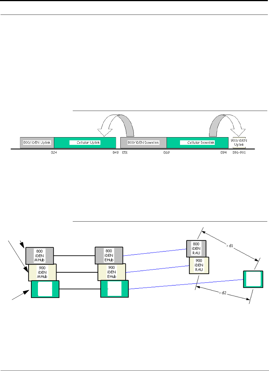
iDEN occupies spectrum at both 800 MHz and 900 MHz (Tx:806–825/Rx:851–870
and Tx:896–901/Rx:935–940), while the Cellular A and B carriers share a single 850
MHz block (Tx:869–894/Rx:824–849). The combination of these frequency bands,
800/900 MHz iDEN and 850 MHz Cellular, result in uplink (BTS receive) bands that
are adjacent to downlink (BTS transmit) bands. Figure 7-9 depicts these nearly con-
tiguous bands, with arrows indicating the interfering downlink and receiving uplink
bands.
Figure 7-9
800/850 MHz Spectrum
Installation of an in-building distributed antenna system (DAS) to provide coverage
for both 800/900 MHz iDEN and 850 MHz Cellular must account for these down-
link-to-uplink interference issues and provide adequate isolation.
LGC offers the following guidelines toward achieving the proper amount of isolation
when deploying LGC Wireless Unison DAS products.
Figure 7-10
Guideline for Unison RAU Antenna Placement
800 MHz iDEN Downlink and 850 MHz Cellular Uplink
A 2 MHz frequency gap (851 – 849 MHz) separates the 800 iDEN downlink and 850
Cellular uplink frequency bands. Because of this narrow spacing, 800 iDEN down-
link intermodulation products may fall within the 850 Cellular uplink band. In addi-
tion, 800 iDEN downlink signals near the lower edge of the band at 851 MHz may
850 850
850
Cellular
MHub
FSN-809019-1 RAU
FSN-8519-1 RAU
850
Cellular
RAU
850
EHub
Cellular
Help Hot Line (U.S. only): 1-800-530-9960 7-29
D-620610-0-20 Rev A
CONFIDENTIAL
Fusion Installation Procedures
cause the 850 Cellular uplink automatic level control (ALC) circuitry in the RAU to
engage and thereby reduce uplink gain.
To prevent either of these conditions, use the following guidelines:
• In-band 800 iDEN intermodulation products < -90dBm
• Lower frequency 800 iDEN signals < –30dBm for Fusion
Given a typical DAS configuration (4 iDEN carriers, omni-directional antennas, line
of sight), these guidelines translate to an antenna spacing (d1) of 6 – 9 meters.
850 MHz Cellular Downlink and 900 MHz iDEN Uplink
A 2 MHz frequency gap (896 – 894 MHz) separates the 850 Cellular downlink and
900 iDEN uplink frequency bands. Because of this narrow spacing, 850 Cellular
downlink intermodulation products may fall within the 900 iDEN uplink band. In
addition, 850 Cellular downlink signals near the upper edge of the band at 894 MHz
may cause the 900 iDEN uplink ALC to engage and thereby reduce uplink gain.
To prevent either of these conditions, use the following guidelines:
• In-band 850 Cellular intermodulation products < -90dBm
• Upper frequency 850 Cellular signals < –30dBm for Fusion
Given a typical DAS configuration (6 CDMA carriers for Fusion, omni-directional
antennas, line of sight), these guidelines translate to an antenna spacing (d2) of 8-14
meters.
Spacing between RAUs FSN-8519-1 and FSN-809019-1 should be in a range of from
8 to 14 meters.
Connecting the Antenna to the RAU
Connect a passive multi-band antenna to the N connector on the RAU using coaxial
cable with the least amount of loss possible.
CAUTION: Firmly hand-tighten the N connector – DO NOT
over-tighten the connector.
Connecting the CATV Cable
Considerations:
• Verify that the cable has been tested and the test results are recorded. This informa-
tion is required for the As-Built Document.
• Verify that only captive centerpin 75 Ohm Type-F connectors are used on the solid
copper center conductor CATV 75 Ohm cable.
• Verify that the CATV cable is labeled with:

Fusion Installation Procedures
7-30 InterReach Fusion Installation, Operation, and Reference Manual
CONFIDENTIAL
D-620610-0-20 Rev A
• Fusion Main Hub port number being used
• RAU identifier
• Carrier (for multiple operator systems)
To connect the CATV cable:
1.
Connect the CATV cables to the F female port on the RAU according to the label
on the cable.
Power is supplied by the Fusion Main Hub over the CATV cable conductors.
Upon power up, the LEDs will blink for two seconds as a visual check that they
are functioning. After the two-second test:
• The
LINK
LED should be green indicating it is receiving power and communi-
cations from the Fusion Main Hub.
• The
ALARM
LED should be red until the Fusion Main Hub issues the band
command, within about 20 seconds, then it should be green.
2.
Record which cable you are connecting to the RAU (from the label on the cable).
This information is required for the As-Built Document.
3.
Tie-off cables or use the optional cable manager to avoid damaging the connectors
because of cable strain.
7.4.3.1 Troubleshooting Using RAU LEDs During Installation
• The
LINK
LED should be green and remain green for longer than 90 seconds. The
ALARM
LEDs are red when the system band has not been programmed.
Table 7-7
Troubleshooting RAU LEDs During Installation
During
Installation LED State Action Impact
The RAU is connected
to the Fusion Expan-
sion Hub, which is
powered on
LINK
Off Check CATV cable. No power to the RAU.
ALARM
Off
LINK
Green • Check CATV cable
• Check Hub LEDs
Refer to page 7-26, item 2 in
Table 7-6.
• Use AdminBrowser to determine the
problem.
The RAU is off-line.
ALARM
Red
LINK
Red from
green, after
cables are
connected for
60 seconds
• Check CATV cable.
• Check the Hub LEDs.
• Use AdminBrowser to determine the
problem.
No communications
between the RAU and the
Hub.
ALARM
Red

Help Hot Line (U.S. only): 1-800-530-9960 7-31
D-620610-0-20 Rev A
CONFIDENTIAL
Fusion Installation Procedures
7.4.3.2 Installing RAUs in a Multiple Operator System
When installing both iDEN and Cellular systems in parallel, either as dual-band or
multiple operator systems, you must take special provision to assure that the individ-
ual RAUs do not interfere with each other.
The 850/1900 MHz and 800/900/1900 MHz RAU’s antennas must be separated
by at least 8 meters (26 feet) to assure that the iDEN downlink signals do not
interfere with the Cellular uplink signals.
7.4.4 Configuring the System
Before the system can operate properly, use AdminBrowser to program the Fusion
Main Hub with the frequency bands that are to be distributed. The Hub must be pro-
grammed with the same frequencies as the RAU used.
NOTE: The frequency bands should automatically be set on power up and
this step should not be required.
Considerations:
• The AdminBrowser software, described in the AdminBrowser User Manual
(PN D-620607-0-20), must be running on a PC/laptop.
• Crossover Ethernet cable with male connectors required.
Connecting the PC to the Fusion Main Hub to Run AdminBrowser
1.
Connect the AC power cord to the Hub.
Make sure the Hub is grounded through the ground lug on the AC power and
the frame ground lug as required. The warranty does not cover damage
caused when an ungrounded Hub is powered on.
2.
Plug the power cord into an AC power outlet.
3.
Verify that all cables are properly connected on the Hub.
4.
Turn on the power to the Hub.
All LEDs blink through the power up sequence. At each port where an RAU is
detected (drawing current), the port LEDs lights green. The Fusion
STATUS
LED
is orange during system boot and should turn green after about 90 seconds if it
finds no faults. This state indicates the band’s are not programmed and provides
feedback on the status of the RAU connections.
The LEDs blink for 20 seconds as a visual check that they are functioning.
5.
Connect the cross-over Ethernet cable to the PC/laptop and then to the
RJ-45
100-BASE-T
port on the Hub’s front panel.
Fusion Installation Procedures
7-32 InterReach Fusion Installation, Operation, and Reference Manual
CONFIDENTIAL
D-620610-0-20 Rev A
Programming the Fusion Main Hub Using AdminBrowser
• Connect the provided TCP/IP crossover cable to the laptop and then to the
Admin/LAN
RJ-45
port on the Fusion Main Hub’s front panel.
• Turn on the laptop and start the Fusion Main Hub.
Windows 2000
1.
Right-click
My Network Places
and select
Properties
.
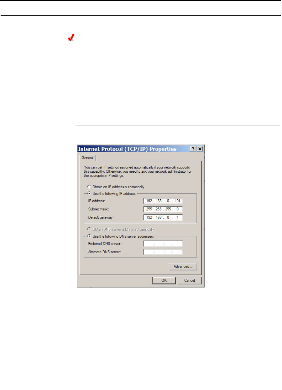
2.
Highlight
Internet Protocol (TCP/IP)
and click
Properties
. A screen similar to
the Figure 7-11 appears.
Figure 7-11
Internet Protocol (TCP/IP) Properties Window
3.
Make note of the current IP address, Subnet mask, and Default gateway, if they
are configured. You will need to re-enter them after you have configured the
Fusion Main Hub.
4.
Select
Use the following IP address
.
5.
Change the
IP address
to 192.168.0.101
6.
Change the
Subnet mask
to 255.255.255.0
7.
Change the
Default gateway
to 192.168.0.1
8.
Click
OK
twice. You may be asked if you want to reboot your computer. If so,
click
Yes
.
Help Hot Line (U.S. only): 1-800-530-9960 7-33
D-620610-0-20 Rev A
CONFIDENTIAL
Fusion Installation Procedures
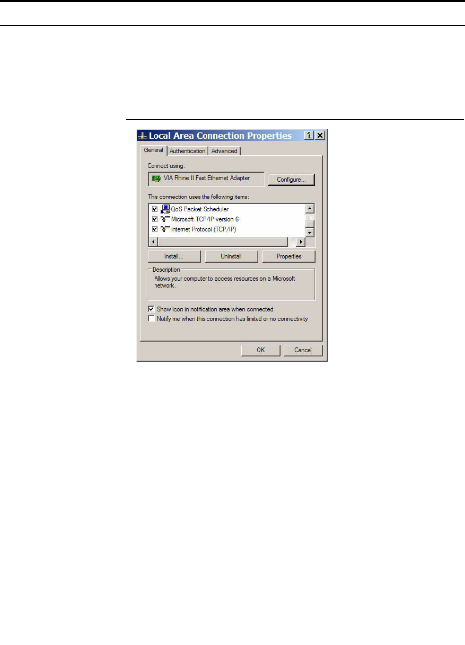
Windows XP
1.
Click
Start>Settings>Network Connections>Local Area Connection
. The win-
dow shown in Figure 7-12 appears.
Figure 7-12
Local Area Connection Properties Window
2.
In the
This connection uses the following items
, scroll down to and select
Internet Protocol (TCP/IP)
and click
Properties
.
3.
Perform steps 3 through 8 in the preceding section.
Using AdminBrowser
1.
Launch your web browser, type
Https://192.168.0.100
in the URL line, and click
Go
.
2.
When AdminBrowser appears, log in using the default password: password.
Fusion Installation Procedures
7-34 InterReach Fusion Installation, Operation, and Reference Manual
CONFIDENTIAL
D-620610-0-20 Rev A
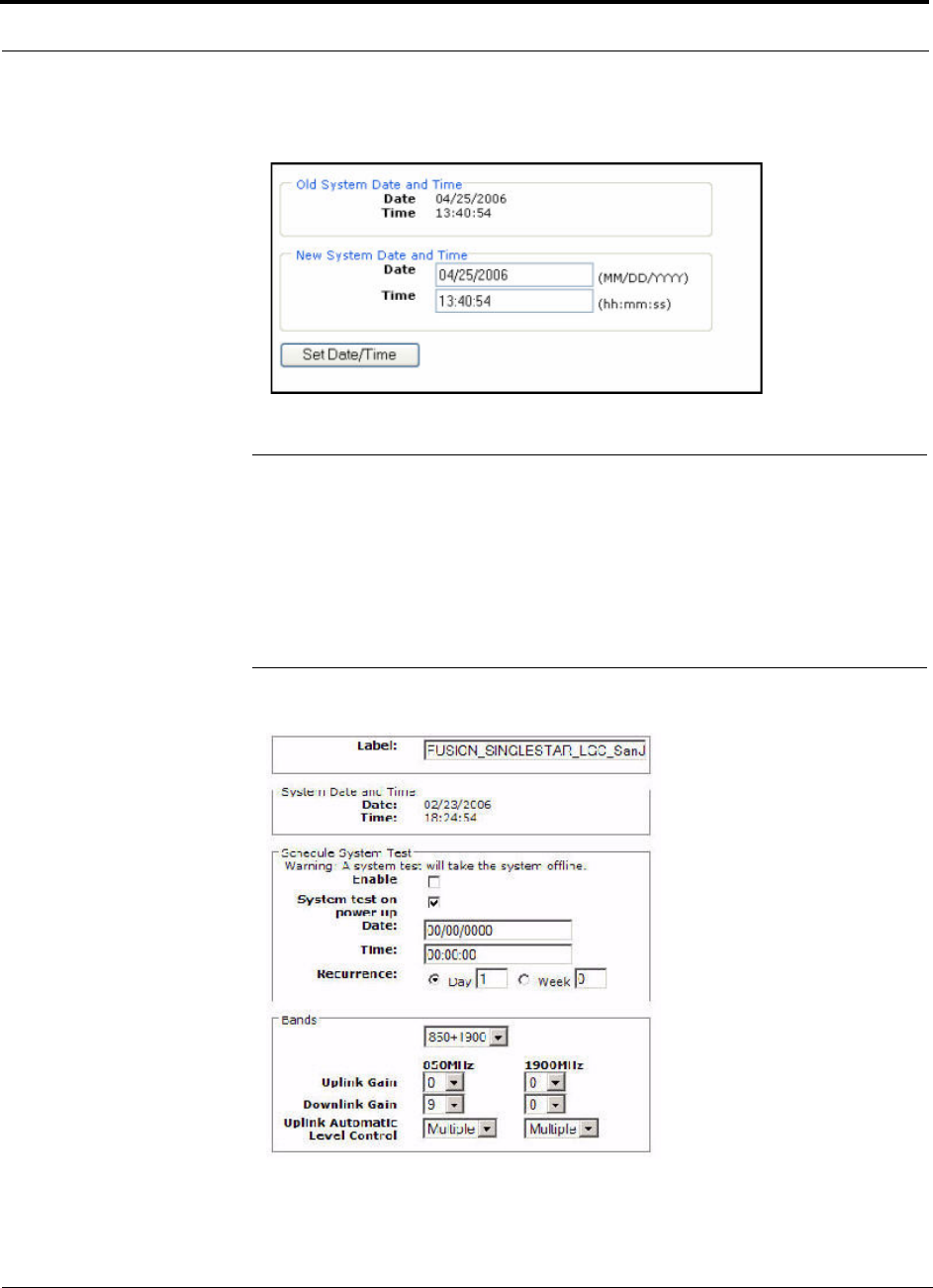
3.
Click System Configuration and then click Set Date/Time. A page similar to
Figure 7-13 appears.
Figure 7-13
Set Time and Date Window
4.
Enter the desired time and date in the format indicated on the page and click Set
Date/Time. A page appears requiring you to reboot the system for the new date
and time to take effect.
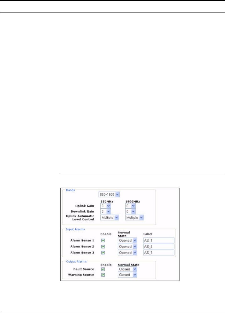
5.
Select the Fusion Main Hub and click Install/Configure System. A screen similar
to the Figure 7-14 appears.
Figure 7-14
AdminBrowser Configuration Window
6.
If desired, type in a label.
Help Hot Line (U.S. only): 1-800-530-9960 7-35
D-620610-0-20 Rev A
CONFIDENTIAL
Fusion Installation Procedures
The label is the system name displayed next to the icons and used in messages.It
can be up to 32 characters long depending upon the firmware version.
The default system label is “Fusion” and will be used if you enter nothing.
7.
Type in a Date and Time or leave the current system date and time unchanged.
Enter time is a 24-hour format.
8.
Use the next section to schedule a System Test.
This section allows you to do the following:
• Click the check box to enable this feature.
• Click the check box to cause system test on power up.
• Enter values to schedule the date and time of the next system test.
• Enter values to specify the recurrence of the test by day or by week.
Schedule System Test allows periodic, automatic execution of the system
end-to-end test. Just like Perform System Test, a Schedule System Test suspends
normal service for the duration of the test; calls are dropped, and no new calls can
be established during the test. Test duration depends on the configuration (number
of RAUs) and requires one or two minutes to complete.
After completion of the system test, the scheduled system test time is updated to
the next test time, and an event log entry is made.
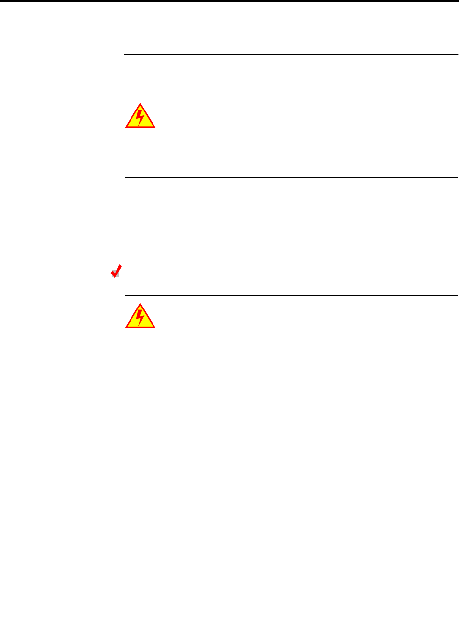
9.
Use the scroll bar on the left side of the page to scroll down to view the rest of the
page as shown in Figure 7-15.
Figure 7-15
AdminBrowser Configuration Window (continued)
10.
In the Band area, do the following:

Fusion Installation Procedures
7-36 InterReach Fusion Installation, Operation, and Reference Manual
CONFIDENTIAL
D-620610-0-20 Rev A
• You should not have to select the bands. The system self configures the band
by validating that all the RAUs connected are the same type.
• Use the pull-down to specify the Uplink and Downlink gain for each band. You
can set system gain within the specified range in 1 dB increments.
• Use the pull-down to set the Uplink Automatic Level Control to either “Single”
or “Multiple” for each band in the system. (The default is “Multiple.”
11.
In the Input/Output Alarms area, do the following for each Alarm Sense:
• Enable each Alarm Sense by using the check box.
• Use the pull-down to set the Normal State to Closed or Opened. (The default is
“Closed.”
• Assign a label to each alarm sense.
12.
When you have completed inputting the desired information, click
Install System
to configure the system.
During configuration all disconnect statuses are cleared for attached RAUs; the
frequency band, gain, and system label are set; logs are cleared; the system test is
performed; and finally the system tree is refreshed. The icons should be:
Indicating that the band is correctly set.
Indicating that communications are OK.
If there are problems, the icons will be different and a message is displayed in the
Messages pane.
13.
Connect the Main Hub to the RF source (for example, BTS or BDA).
Do not exceed the maximum input RF power (1 Watt) to the Fusion Main
Hub. Exceeding the limit could cause permanent damage to the Hub.
CAUTION:Only carriers and their approved installers or LGC-authorized
installers are allowed to connect to the RF source. Serious damage to the
equipment can occur if it is over-driven.
The Fusion system should now be operational. Using a mobile phone, walk your
site and test the signal strength.
14.
Make sure to change the TCP/IP setting in your laptop back to their original val-
ues.
NOTE: NOTE: LGC Wireless’ equipment is designed to operate in the
licensed frequency bands of mobile, cellular, and PCS operators. In the
USA, the EU, and most countries this equipment may only be used by the
licensee, his authorized agents or those with written authorization to do so.
Similarly, unauthorized use is illegal, and subjects the owner to the corre-

Help Hot Line (U.S. only): 1-800-530-9960 7-37
D-620610-0-20 Rev A
CONFIDENTIAL
Splicing Fiber Optic Cable
sponding legal sanctions of the national jurisdiction involved. Ownership of
LGC Wireless equipment carries no automatic right of use.
7.5 Splicing Fiber Optic Cable
The fiber cable must have SC/APC connectors for the entire run. If it does not, you
can splice a pigtail, which has SC/APC connectors, to the fiber cable.
LGC offers two pigtails: one for single-mode fiber (PN 4013SCAPC-3) and one for
multi-mode fiber (PN 4012SCAPC-3).
LGC Wireless recommends fusion splices because they have the lowest splice loss
and return loss. Mechanical splices have higher losses and higher back reflection than
fusion splices and are not recommended.
Using a fusion splicer involves fusing together two butted and cleaved ends of fiber.
The fusion splicer aligns the fibers and maintains alignment during the fusion pro-
cess. Fusion splices have very low loss (typically less than 0.05 dB) and very low
back reflection (return loss). Fusion splices should be organized in a splice tray
designed to store and protect the splices.
Fusion Splicing of Fiber and Pigtail
Before you begin, make sure the fusion splicer is set to the proper mode (that is, sin-
gle- or multi-mode).
To fusion splice the fiber optic cable to the SC/APC pigtail: Option A
1.
Secure both the fiber cable and the SC/APC pigtail in a splice tray that is installed
immediately adjacent to the Hub.
2.
Prepare the fiber end by cutting back the polyethylene jacket, the kevlar or fiber-
glass strength members, the extruded coating, and the buffer coating in order to
expose the “bare fiber” – cladding plus core.
Ensure that sufficient slack is maintained in order to be able to reach the fusion
splicer.
3.
Clean the unclad fiber core using isopropyl alcohol and lint-free wipes.
4.
Cleave the unclad fiber to the length prescribed by the fusion splicer’s specifica-
tion sheets.
5.
Repeat steps 2 through 4 for the SC/APC pigtail.
6.
Pass the splice sleeve onto the fiber strand.
7.
Position both fiber ends in the fusion splicer and complete splice in accordance
with the fusion splicer’s operation instructions.

Splicing Fiber Optic Cable
7-38 InterReach Fusion Installation, Operation, and Reference Manual
CONFIDENTIAL
D-620610-0-20 Rev A
8.
Ensure that the estimated loss for the splice as measured by the fusion splicer is
0.10 dB or better.
9.
Slide the fusion splicing sleeve over the point of the fusion splice.
10.
Place the sleeve and fused fiber into the fusion splicer’s heater.
11.
Allow time for the splice sleeve to cure.
12.
Return fiber splice to the splice tray, store the sleeve in a splice holder within the
tray, and store excess cable length in accordance with the tray manufacture’s
directions.
After successfully testing the fiber, plug the SC/APC pigtail into the proper opti-
cal port on the Hub.
To fusion splice the fiber optic cable to the SC/APC pigtail: Option B
1.
Secure both the fiber cable and the SC/APC pigtail in a splice tray portion of a
fiber distribution panel.
2.
Prepare the fiber end by cutting back the polyethylene jacket, the kevlar or fiber-
glass strength members, the extruded coating, and the buffer coating in order to
expose the “bare fiber” – cladding plus core.
Ensure that sufficient slack is maintained in order to be able to reach the fusion
splicer.
3.
Clean the unclad fiber core using isopropyl alcohol and lint-free wipes.
4.
Cleave the unclad fiber to the length prescribed by the fusion splicer’s specifica-
tion sheets.
5.
Repeat steps 2 through 4 for the SC/APC pigtail.
6.
Pass the splice sleeve onto the fiber strand.
7.
Position both fiber ends in the fusion splicer and complete splice in accordance
with the fusion splicer’s operation instructions.
8.
Ensure that the estimated loss for the splice as measured by the fusion splicer is
0.10 dB or better.
9.
Slide the fusion splicing sleeve over the point of the fusion splice.
10.
Place the sleeve and fused fiber into the fusion splicer’s heater.
11.
Allow time for the splice sleeve to cure.
12.
Return fiber splice to the splice tray, store the sleeve in a splice holder within the
tray, and store excess cable length in accordance with the tray manufacture’s
directions.
13.
After successfully testing the fiber cable, plug the SC/APC pigtail into the back
side of the SC/APC bulkhead in the Fiber Distribution Panel.
Install a SC/APC patch cord between the front side of the SC/APC bulkhead and
the proper optical port on the Hub.
NOTE: Refer to Section 9 for troubleshooting.
Help Hot Line (U.S. only): 1-800-530-9960 7-39
D-620610-0-20 Rev A
CONFIDENTIAL
Interfacing the Fusion Main Hub to an RF Source
7.6 Interfacing the Fusion Main Hub to an RF Source
WARNING: Only LGC personnel or LGC-authorized installation per-
sonnel should connect the Fusion Main Hub to its Band associated base
station or repeater. Exceeding the maximum input power could cause
failure of the Fusion Main Hub (refer to Section 5.2 on page 5-4 for maximum
power specifications). If the maximum composite power is too high, attenuation
is required.
7.6.1 Connecting a Single Fusion Main Hub to an RF Source
The Fusion system supports three RF sources, one for Band 1, Band 2, and Band 3.
This section explains how each Band can be connected to its associated RF source.
Connecting a Fusion Main Hub to an In-Building BTS
WARNING: Only LGC personnel or LGC-authorized installation per-
sonnel should connect the Fusion Main Hub to a base station or
repeater. Exceeding the maximum input power could cause failure of
the Fusion Main Hub (refer to Section 5.2 on page 5-4 for maximum power spec-
ifications). If the maximum composite power is too high, attenuation is required.
CAUTION:The
UPLINK
and
DOWNLINK
ports cannot handle a DC power
feed from the base station. If DC power is present, a DC block must be used
or the hub may be damaged.
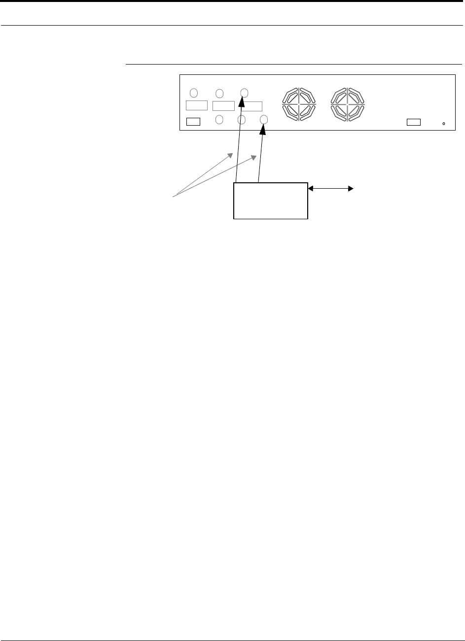
Connecting a Simplex Base Station to a Fusion Main Hub RF Band:
1.
Connect an N-male to N-male coaxial cable to the transmit simplex connector on
the base station.
2.
Connect the other end of the N-male to N-male coaxial cable to the
DOWNLINK
connector on the Hub for the corresponding Band 1, Band 2, or Band 3.
3.
Connect an N-male to N-male coaxial cable to the receive simplex connector on
the base station.
4.
Connect the other end of the N-male to N-male coaxial cable to the
UPLINK
con-
nector on the Hub for the corresponding Band 1, Band 2, or Band 3.
Interfacing the Fusion Main Hub to an RF Source
7-40 InterReach Fusion Installation, Operation, and Reference Manual
CONFIDENTIAL
D-620610-0-20 Rev A
Figure 7-16
Simplex Base Station to a Fusion Main Hub
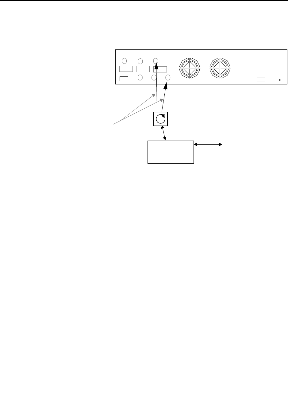
Connecting a Duplex Base Station to a Fusion Main Hub:
When connecting to a duplex base station, use a circulator or duplexer between it and
the Fusion Main Hub.
You can insert attenuators between the circulator or duplexer and Hub as needed.
1.
Connect an N-male to N-male coaxial cable to the duplex connector on the base
station.
2.
Connect the other N-male connector or duplexer to a circulator.
3.
Connect an N-male to N-male coaxial cable to the
DOWNLINK
connector on the
Hub for Band 1, Band 2, and Band 3.
4.
Connect the other end of the N-male coaxial cable to the transmit connector on the
circulator.
5.
Connect an N-male to N-male coaxial cable to the
UPLINK
connector on the Hub
for Band 1, Band 2, and Band 3.
6.
Connect the other end of the N-male coaxial cable to the receive connector on the
circulator.
N-male to N-male
Coaxial Cable
Base Station
Simplex T1/E1 to
Mobile
Switching
Center
Insert attenuator, if needed
Note: This applies to either Band 1, Band 2, and Band 3.
Band 1 Band 2 Band 3
UL1 UL2 UL3
DL1 DL2 DL3
AC Power
Alarms
Band 3
Help Hot Line (U.S. only): 1-800-530-9960 7-41
D-620610-0-20 Rev A
CONFIDENTIAL
Interfacing the Fusion Main Hub to an RF Source
Figure 7-17
Duplex Base Station to a Fusion Main Hub
N-male to N-male
Coaxial Cable
Base Station
Duplex T1/E1 to
Mobile
Switching
Center
Insert attenuator, if needed N-male to N-male
Coaxial Cable
Note: This applies to either Band 1, Band 2, Band 3.
Band 1 Band 2 Band 3
UL1 UL2 UL3
DL1 DL2 DL3
AC Power
Alarms
Circulator
Interfacing the Fusion Main Hub to an RF Source
7-42 InterReach Fusion Installation, Operation, and Reference Manual
CONFIDENTIAL
D-620610-0-20 Rev A
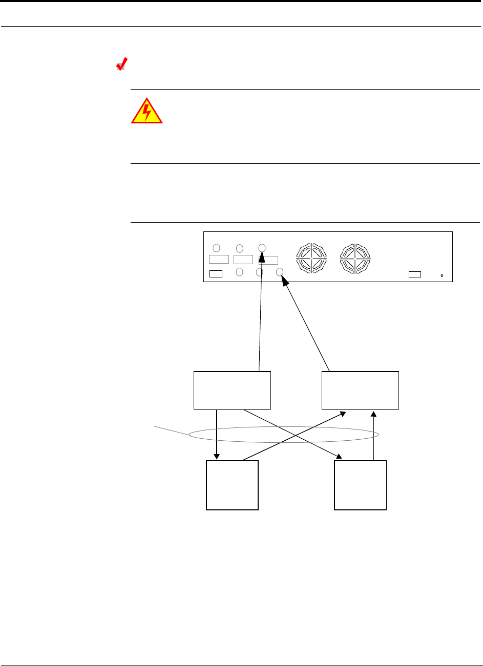
Connecting a Fusion Main Hub RF Band to Multiple BTSs
WARNING: Only LGC personnel or LGC-authorized installation per-
sonnel should connect the Fusion Main Hub to a base station or
repeater. Exceeding the maximum input power could cause failure of
the Fusion Main Hub (refer to Section 5.2 on page 5-4 for maximum power spec-
ifications). If the maximum composite power is too high, attenuation is required.
You can use power combiner/splitters to connect a Fusion Main Hub RF Band to mul-
tiple base stations, as shown in Figure 7-18.
Figure 7-18
Connecting a Fusion Main Hub to Multiple Base Stations
N-male to N-male
Coaxial Jumper Cables
N-male to N-male
Coaxial Jumper Cable
to Repeater or
Base Station
between Combiner/Splitter and
N-male to N-male
Coaxial Jumper Cables
between Combiner/Splitter and
Fusion Main Hub’s Uplink Port Fusion Main Hub’s Downlink Port for
2 x 1 Power
Combiner/Splitter
2 x 1 Power
Combiner/Splitter
BTS 1
UL DL
BTS 2
UL DL
Insert attenuators, if needed
for each on Band 1, Band 2, or Band 3 either Band 1, Band 2, or Band 3
Band 1 Band 2 Band 3
UL1 UL2 UL3
DL1 DL2 DL3
AC Power
Alarms
Help Hot Line (U.S. only): 1-800-530-9960 7-43
D-620610-0-20 Rev A
CONFIDENTIAL
Interfacing the Fusion Main Hub to an RF Source
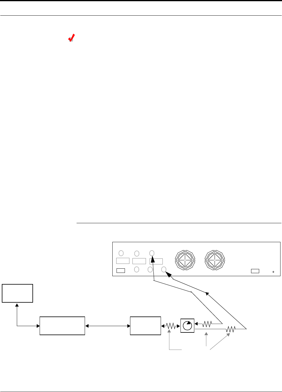
Connecting a Fusion Main Hub to a Roof-top Antenna
LGC Wireless recommends that you use a lightning arrestor or surge protector in a
roof-top antenna configuration. Insert the lightning arrestor or surge protector
between the roof-top antenna and the repeater connected to the Fusion Main Hub RF
Band.
1.
Connect an N-male to N-male coaxial cable to the roof-top antenna.
2.
Connect the other end of the N-male to N-male coaxial cable to the grounded
surge suppressor.
3.
Connect an N-male to N-male coaxial cable to the grounded surge suppressor.
4.
Connect the other end of the N-male to N-male coaxial cable to the repeater.
5.
Connect an N-male to N-male coaxial cable to the repeater.
6.
Connect the other end of the N-male to N-male coaxial cable to the circulator
1
connector.
7.
Connect an N-male to N-male coaxial cable to the circulator
2
connector.
8.
Connect the other end of the N-male to N-male coaxial cable to the
DOWNLINK
connector on the Hub for either Band 1, Band 2, or Band 3.
Attenuation may be required to achieve the desired RF output at the RAU.
9.
Connect an N-male to N-male coaxial cable to the circulator
3
connector.
10.
Connect the other end of the N-male to N-male coaxial cable to the
UPLINK
con-
nector on the Hub for either Band 1, Band 2, or Band 3.
Figure 7-19
Connecting a Fusion Main Hub to a Roof-top Antenna
Roof-top
Antenna
Grounded
Surge Suppressor Repeater
N-male to N-male
Coaxial Cables
N-male to N-male
Coaxial Cable
N-male to N-male
Coaxial Cable Circulator
Attenuator
(optional)
Note: This applies to either Band 1, Band 2, or Band 3.
Band 1 Band 2 Band 3
UL1 UL2 UL3
DL1 DL2 DL3
AC Power
Alarms
12
3

Interfacing the Fusion Main Hub to an RF Source
7-44 InterReach Fusion Installation, Operation, and Reference Manual
CONFIDENTIAL
D-620610-0-20 Rev A
Connecting a Fusion Main Hub to MetroReach Focus
Refer to the MetroReach Focus manual for information.
7.6.2 Connecting Multiple Fusion Main Hubs to an RF Source
You can use power combiner/splitters as splitters to connect multiple Fusion Main
Hubs in order to increase the total number of RAUs in a system. You can also use
power combiner/splitters to combine base station channels in order to increase the
number of RF carriers the system transports.
Connecting Multiple Fusion Main Hubs to a Simplex Repeater or
BTS
WARNING: Only LGC personnel or LGC-authorized installation per-
sonnel should connect the Fusion Main Hub to a base station or
repeater. Exceeding the maximum input power could cause failure of
the Fusion Main Hub (refer to Section 5.2 on page 5-4 for maximum power spec-
ifications). If the maximum composite power is too high, attenuation is required.
Considerations:
• 2 hybrid power combiner/splitters; one for uplink and one for downlink (2x1 for
two Fusion Main Hubs, 3x1 for three, 4x1 for four, and so on.)
• 1 N-male to N-male coaxial jumper cable between each power combiner/splitter
and the base station
• 2 N-male to N-male coaxial jumper cables between each power combiner/splitter
and each Fusion Main Hub RF Band (either Band 1 or Band 2)
Procedure:
1.
Connect the power combiner/splitters to the repeater or base station using N-male
to N-male coaxial jumper cables:
a.
From the first power combiner/splitter to the repeater or base station
UPLINK
b.
From the second power combiner/splitter to the repeater or base station
DOWNLINK
2.
Connect the power combiner/splitters to the Hubs:
a.
From the first Hub’s
UPLINK
port (Band 1, Band 2, or Band 3) to the first
power combiner/splitter
b.
From the first Hub’s
DOWNLINK
port (Band 1, Band 2, or Band 3) to the sec-
ond power combiner/splitter
c.
From the second Hub’s
UPLINK
port (Band 1, Band 2, or Band 3) to the first
power combiner/splitter
d.
From the second Hub’s
DOWNLINK
port (Band 1, Band 2, or Band 3) to the
second power combiner/splitter

Help Hot Line (U.S. only): 1-800-530-9960 7-45
D-620610-0-20 Rev A
CONFIDENTIAL
Interfacing the Fusion Main Hub to an RF Source
NOTE: Connections should not cross Bands. For example, all Band 1 connections
should be made to the same hybrid power combiner/splitter connected to the repeater
BTS that matches the Band 1 frequency.
3.
Check Hub LEDs.
After connecting and powering on the Hub, check all LEDs to ensure that the sys-
tem is operating properly.
Make sure the Hub is grounded. The warranty does not cover damage caused
when an ungrounded Hub is powered on.
NOTE: Use a 50 ohm terminator on any unused power combiner/splitter ports.
Figure 7-20 shows how to connect two Main Hubs to a simplex repeater or base sta-
tion. Connecting two Hubs increases the total number of supportable RAUs from 8 to
16.
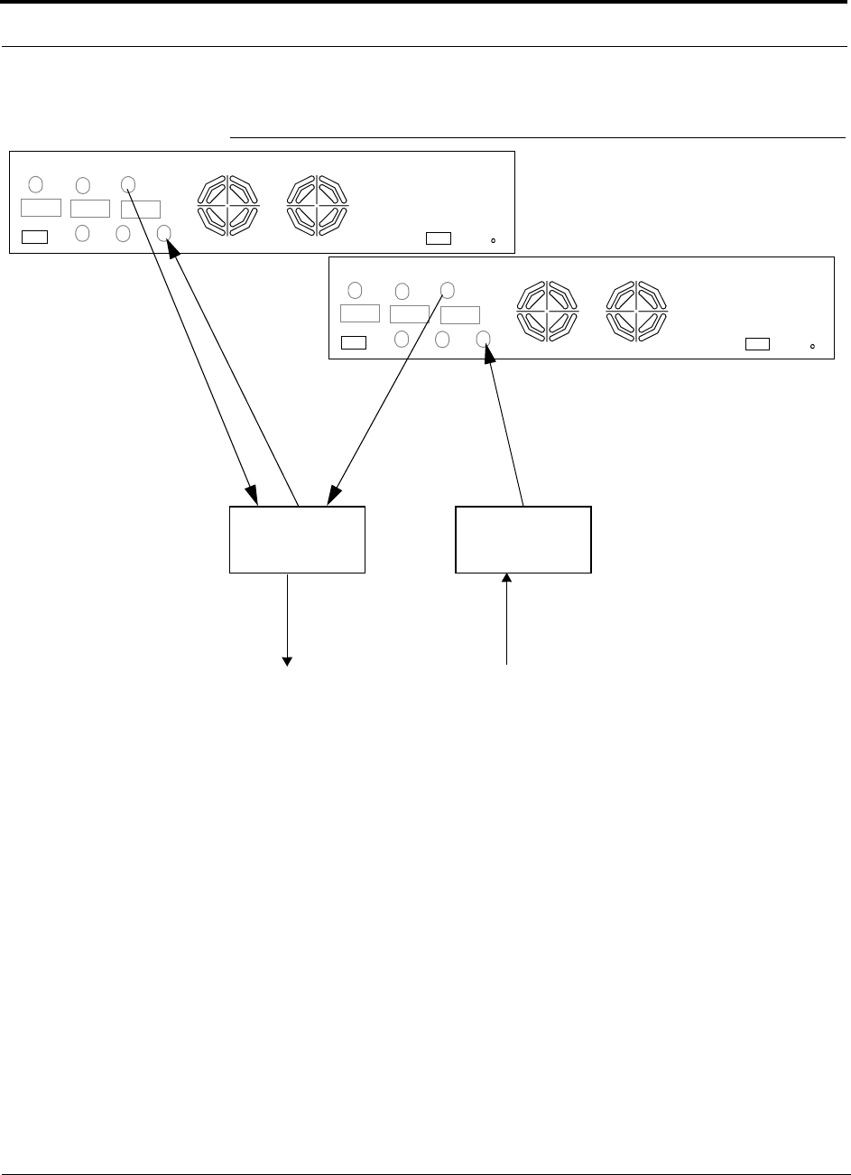
Interfacing the Fusion Main Hub to an RF Source
7-46 InterReach Fusion Installation, Operation, and Reference Manual
CONFIDENTIAL
D-620610-0-20 Rev A
Figure 7-20
Connecting Two Fusion Main Hub’s RF Band Ports to a Simplex
Repeater or Base Station
N-male to N-male
Coaxial Jumper Cables
N-male to N-male
Coaxial Jumper Cable
to Repeater or
Base Station
2 x 1 Power
Combiner/Splitter
N-male to N-male
Coaxial Jumper Cable
to Repeater or
Base Station
between Combiner/Splitter and
N-male to N-male
Coaxial Jumper Cables
between Combiner/Splitter and
Fusion Main Hub’s Uplink Port for
Fusion Main Hub’s Downlink Port for
2 x 1 Power
Combiner/Splitter
either Band, Band 2, Band 3
either Band 1, Band 2, Band 3
Band 1 Band 2 Band 3
UL1 UL2 UL3
DL1 DL2 DL3
AC Power
Alarms
Band 1 Band 2 Band 3
UL1 UL2 UL3
DL1 DL2 DL3
AC Power
Alarms

Help Hot Line (U.S. only): 1-800-530-9960 7-47
D-620610-0-20 Rev A
CONFIDENTIAL
Interfacing the Fusion Main Hub to an RF Source
Connecting Multiple Fusion Main Hubs to a Duplex Repeater or
BTS
WARNING: Only LGC personnel or LGC-authorized installation per-
sonnel should connect the Fusion Main Hub to a base station or
repeater. Exceeding the maximum input power could cause failure of
the Fusion Main Hub (refer to Section 5.2 on page 5-4 for maximum power spec-
ifications). If the maximum composite power is too high, attenuation is required.
Considerations:
• 2 hybrid power combiner/splitters; one for uplink and one for downlink (2x1 for
two Fusion Main Hubs, 3x1 for three, 4x1 for four, and so.)
• 2 N-male to N-male coaxial jumper cables to connect each Fusion Main Hub’s RF
Band to the power combiner/splitters
• 1 circulator
• 1 N-male to N-male coaxial jumper cable between each circulator and the repeater
or base station
• 1 N-male to N-male coaxial jumper cable between each circulator and power com-
biner/splitter
Procedure:
1.
Connect the circulator to the repeater or base station using one N-male to N-male
coaxial jumper cable.
2.
Connect each power combiner/splitter to the circulator using one N-male to
N-male coaxial jumper cable per combiner/splitter.
3.
Connect the power combiner/splitter to the Hubs using N-male to N-male coaxial
jumper cable:
a.
From the first Hub’s
UPLINK
(Band 1, Band 2, or Band 3) port to the first
power combiner/splitter
b.
From the first Hub’s
DOWNLINK
(Band 1, Band 2, or Band 3) port to the sec-
ond power combiner/splitter
c.
From the second Hub’s
UPLINK
(Band 1, Band 2, or Band 3) port to the first
power combiner/splitter
d.
From the second Hub’s
DOWNLINK
(Band 1, Band 2, or Band 3) port to the
second power combiner/splitter
NOTE: Connections should not cross Bands. For example, all Band 1 connections
should be made to the same hybrid power combiner/splitter connected to the repeater
BTS that matches the Band 1 frequency.
4.
Check Hub LEDs.
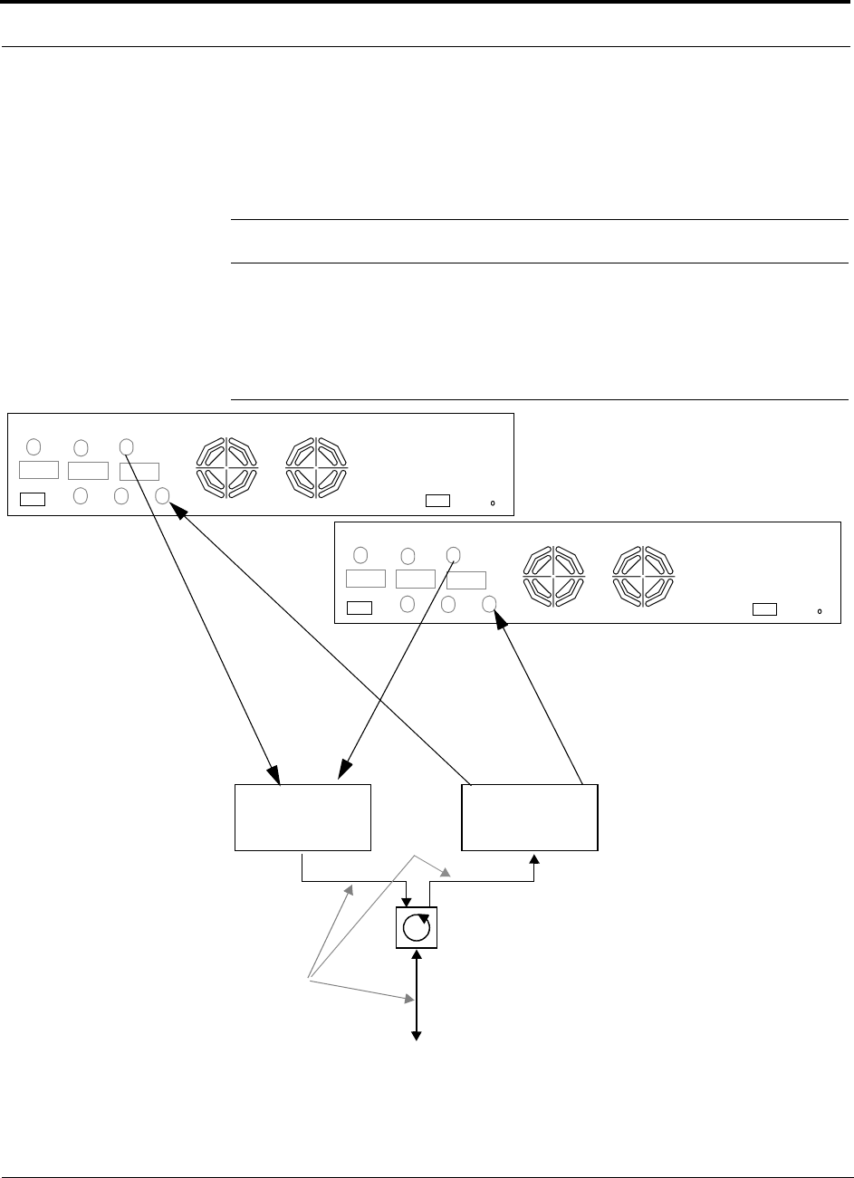
Interfacing the Fusion Main Hub to an RF Source
7-48 InterReach Fusion Installation, Operation, and Reference Manual
CONFIDENTIAL
D-620610-0-20 Rev A
After connecting and powering on the Hub, check all LEDs to ensure that the sys-
tem is operating properly.
Make sure the Main Hub is grounded. The warranty does not cover damage
caused when an ungrounded Hub is powered on.
NOTE: Use a 50 ohm terminator on any unused power combiner/splitter ports.
Figure 7-21 shows how to connect two Hubs to a duplex repeater or base station. You
need to use one circulator and one more coaxial jumper cable, as shown.
Figure 7-21
Connecting Two Fusion Main Hub’s RF Band Ports to a Duplex
Repeater or Base Station
N-male to N-male
Coaxial Jumper Cables
2 x 1 Power
Combiner/Splitter
between Combiner/Splitter and
N-male to N-male
Coaxial Jumper Cables
between Combiner/Splitter and
Fusion Main Hub’s Uplink Port
Fusion Main Hub’s Downlink Port for
2 x 1 Power
Combiner/Splitter
N-male to N-male
Coaxial Jumper Cable
N-male to N-male
Coaxial Jumper Cable
Circulator
N-male to N-male
Coaxial Jumper Cable
to Repeater or
Base Station
Insert attenuator, if needed
for either Band 1, Band 2,
either Band 1, Band 2, or Band 3
or Band 3
Band 1 Band 2 Band 3
UL1 UL2 UL3
DL1 DL2 DL3
AC Power
Alarms
Band 1 Band 2 Band 3
UL1 UL2 UL3
DL1 DL2 DL3
AC Power
Alarms

Help Hot Line (U.S. only): 1-800-530-9960 7-49
D-620610-0-20 Rev A
CONFIDENTIAL
Connecting Contact Alarms to a Fusion System
7.7 Connecting Contact Alarms to a Fusion System
The Fusion Main Hub can generate (source) two contact alarms as well as sense three
external contact alarm.
• Alarm Source (refer to Section 7.7.1 on page 7-50)
The Fusion Main Hub has two alarm contacts, fault (major) and warning (minor).
These contacts are normally-closed (NC) and will open when an internal alarm is
detected.
NOTE: The contact can be changed to normally-open (NO) with Admin-
Browser. This is not recommended since no alarm would be sent if power to
the Fusion Main Hub fails.
• Fault is activated when any faults or disconnects are detected.
• Warning is activated when any warning conditions are detected except lockout
or when the end-to-end system test is not valid.
• Alarm Sense (refer to Section 7.7.2 on page 7-53)
The Fusion Main Hub can monitor 3 external alarm contacts. Each port can be con-
figured for normally-open (NO) or normally-closed (NC) contacts. The interface
expects a set of floating contacts, and an external voltage source is not required for
this interface. Use AdminBrowser to monitor the port status.
Table 7-8 lists the alarm types, equipment to which the Fusion Main Hub is con-
nected, cable(s) used, and the faults and warnings that are detected.
Table 7-8
Alarm Types
Note that Unison and MetroReach Focus support only faults (major errors).
Alarm
Type
Fusion
Connected to Cable(s) Used Errors Detected
Source MetroReach 5-port Alarm Daisy-Chain Cable Faults
Source BTS 5-port Alarm Daisy-Chain Cable Faults and Warnings
In addition, a custom daisy-chain cable-to-BTS interface
cable is required. Make this interface cable to the desired
length and with the appropriate pin placement.
Sense Unison 5-port Alarm Daisy-Chain Cable
and the Alarm Sense Adapter
Cable
Faults
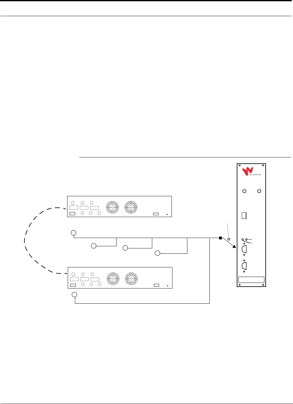
Connecting Contact Alarms to a Fusion System
7-50 InterReach Fusion Installation, Operation, and Reference Manual
CONFIDENTIAL
D-620610-0-20 Rev A
Do not mix Unison and Fusion Main Hubs in the same daisy-chain. You can
daisy-chain multiple Unison Hubs together and use the Alarm Sense Adapter Cable to
connect the chain to a Fusion Main Hub, which will act as an alarm sensor.
7.7.1 Alarm Source
Fusion always acts as an alarm source, no matter what type of equipment you are con-
necting to. Refer to Section 7.7.2 on page 7-53 if you want Fusion to sense Unison
contact closures or other external alarms.
Using MetroReach Focus to Monitor Fusion
When you connect MetroReach Focus to the Fusion, the Fusion Main Hub is the out-
put of the alarms (alarm source) and Focus is the input (alarm sense), as shown in
Figure 7-22. Focus supports only faults (major errors).
Figure 7-22
Connecting MetroReach to Fusion
RF OUT
DOWNLINK
RF IN
UPLINK
FIBER
UPLINK
DOWNLINK
ALARM
RS-232C
MetroReach
Focus
RFM
Alarm
Sense
Alarm
Source
Alarm
Source
5-port Alarm Daisy-Chain Cable
May need
9-pin Adapter,
which ships
with the cable
Fusion Main Hub
Band 1 Band 2 Band 3
UL1 UL2 UL3
DL1 DL2 DL3
AC Power
Alarms
Band 1 Band 2 Band 3
UL1 UL2 UL3
DL1 DL2 DL3
AC Power
Alarms
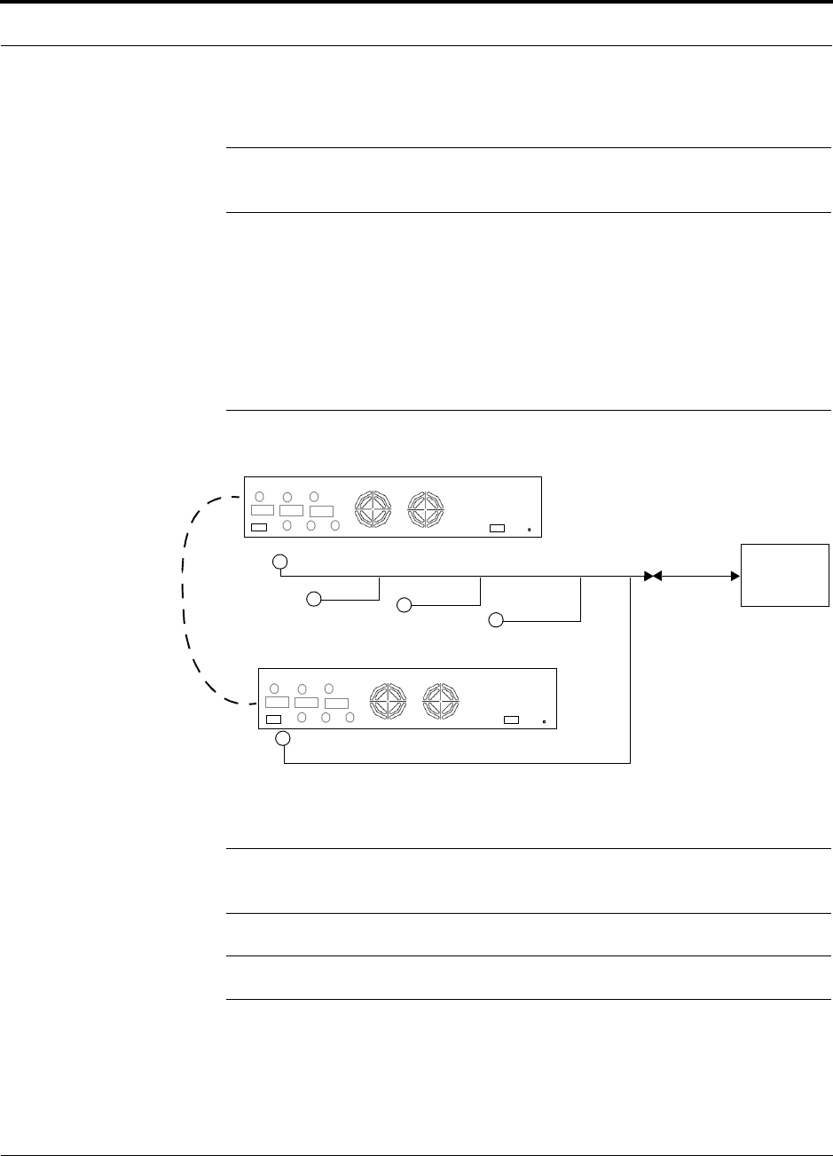
Help Hot Line (U.S. only): 1-800-530-9960 7-51
D-620610-0-20 Rev A
CONFIDENTIAL
Connecting Contact Alarms to a Fusion System
Using a Base Station to Monitor Fusion
NOTE: The BTS must be configured, by the carrier, for contact closure monitoring
prior to connecting a Fusion Main Hub to it.
When you connect a BTS to Fusion, the Fusion Main Hub is the output of the alarms
(alarm source) and the BTS is the input (alarm sense), as shown in Figure 7-23. An
interface cable is required between the daisy-chain cable and the BTS. Because BTS
alarm interface pinouts and Fusion-to-BTS distances vary, this cable is often custom
and wired on-site. Refer to Section 3.2.1 for Alarm Contact details (Normally
Closed).
Figure 7-23
Using a BTS to Monitor Fusion
NOTE: For normally open contacts, the fault and warning contacts need to
be wired in parallel with other Main Hubs.
NOTE: LGC Wireless does not recommend using normally open contacts.
BTS
Interface
Cable
Alarm
Sense
Alarm
Source
Alarm
Source
5-port Alarm Daisy-Chain Cable
Fusion Main Hub
(custom made, on-site)
Band 1 Band 2 Band 3
UL1 UL2 UL3
DL1 DL2 DL3
AC Power
Alarms
Band 1 Band 2 Band 3
UL1 UL2 UL3
DL1 DL2 DL3
AC Power
Alarms
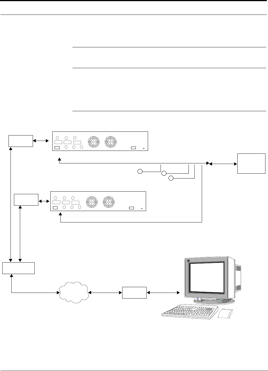
Connecting Contact Alarms to a Fusion System
7-52 InterReach Fusion Installation, Operation, and Reference Manual
CONFIDENTIAL
D-620610-0-20 Rev A
Using a Base Station and AdminBrowser to Monitor Fusion
NOTE: The BTS must be configured, by the carrier, for contact closure monitoring
prior to connecting a Fusion Main Hub to it.
In order to take full advantage of Fusion’s OA&M capabilities you can use LGC
Wireless’ AdminBrowser software in addition to a BTS to monitor the system, as
shown in Figure 7-24. Refer to Section 7.8.6 for SNMP optional feature capabilities.
Figure 7-24
Using a BTS and AdminBrowser to Monitor Fusion
Line Switch
Straight-through modem cable connected
to Fusion Main Hub’s front panel serial port
PSTN
Modem
PC running
Standard Browser
Software
BTS
Interface
Cable
Alarm
Sense
Alarm
Source
Alarm
Source
5-port Alarm Daisy-Chain Cable
Fusion Main Hub
Modem
Modem
Band 1 Band 2 Band 3
UL1 UL2 UL3
DL1 DL2 DL3
AC Power
Alarms
Band 1 Band 2 Band 3
UL1 UL2 UL3
DL1 DL2 DL3
AC Power
Alarms
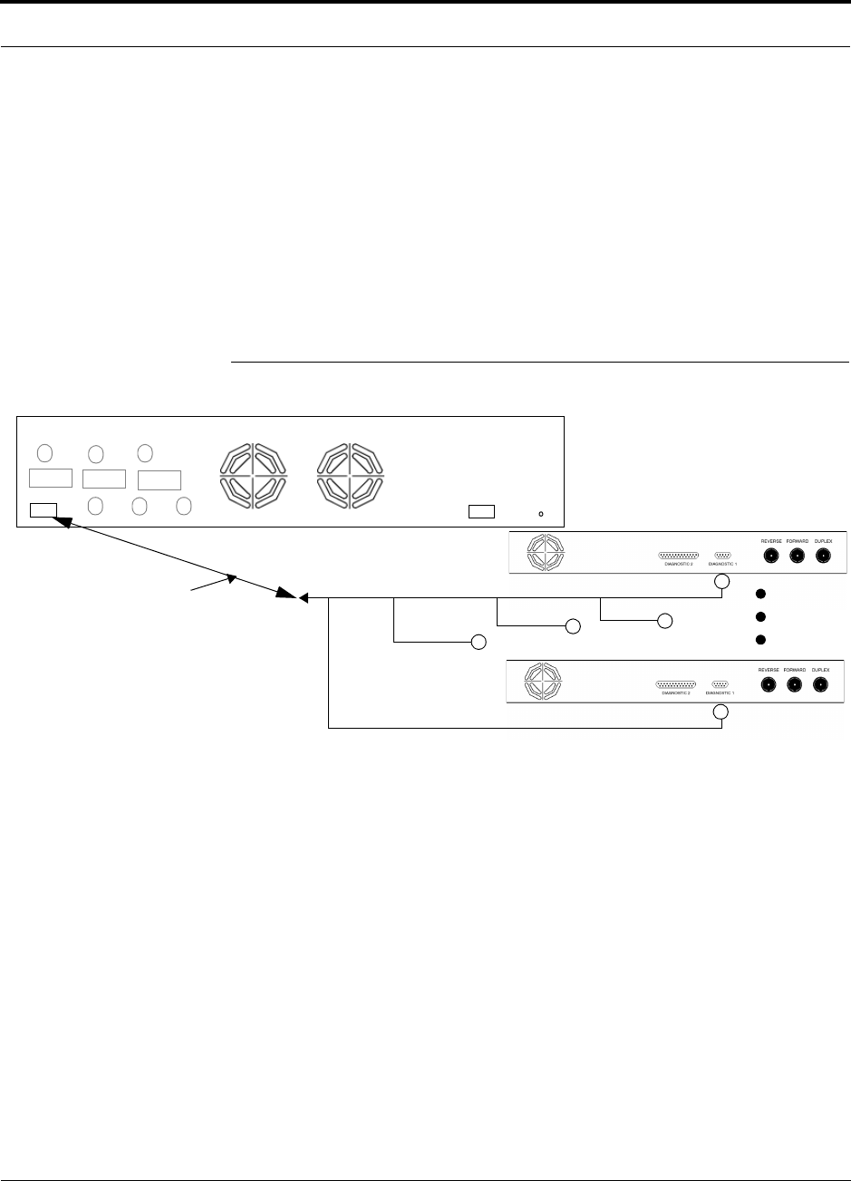
Help Hot Line (U.S. only): 1-800-530-9960 7-53
D-620610-0-20 Rev A
CONFIDENTIAL
Connecting Contact Alarms to a Fusion System
7.7.2 Alarm Sense
Use AdminBrowser to enable the Fusion system for “alarm sense” when connecting
to the contact closure of Unison Main Hubs or other external alarms (refer to Set
Contact Sense Properties in the AdminBrowser User Manual).
Using Fusion to Monitor Unison
When you connect Unison to Fusion, the Fusion Main Hub is the input of the alarms
(alarm sense) and the Unison is the output (alarm source), as shown in Figure 7-25.
The input alarm sense needs to be set to normally closed (NC).
Figure 7-25
Using Fusion to Monitor Unison
Unison supports only faults. You must use the Alarm Sense Adapter Cable (refer to
page 7-56) to interface the daisy-chain cable to Fusion. The adapter cable is required
because it translates the Unison fault pinout to the sense input pins on the Fusion
Main Hub.
Up to 5 Unison Main Hubs
Fusion Main Hub
Alarm
Sense Alarm
Source
Alarm
Source
Alarm Sense
Adapter Cable
5-port Alarm Daisy-Chain Cable
Band 1 Band 2 Band 3
UL1 UL2 UL3
DL1 DL2 DL3
AC Power
Alarms

Connecting Contact Alarms to a Fusion System
7-54 InterReach Fusion Installation, Operation, and Reference Manual
CONFIDENTIAL
D-620610-0-20 Rev A
Figure 7-26
Alarm Sense Contacts
8
1
Diagnostic I
External
Equipment
Contacts
+5V
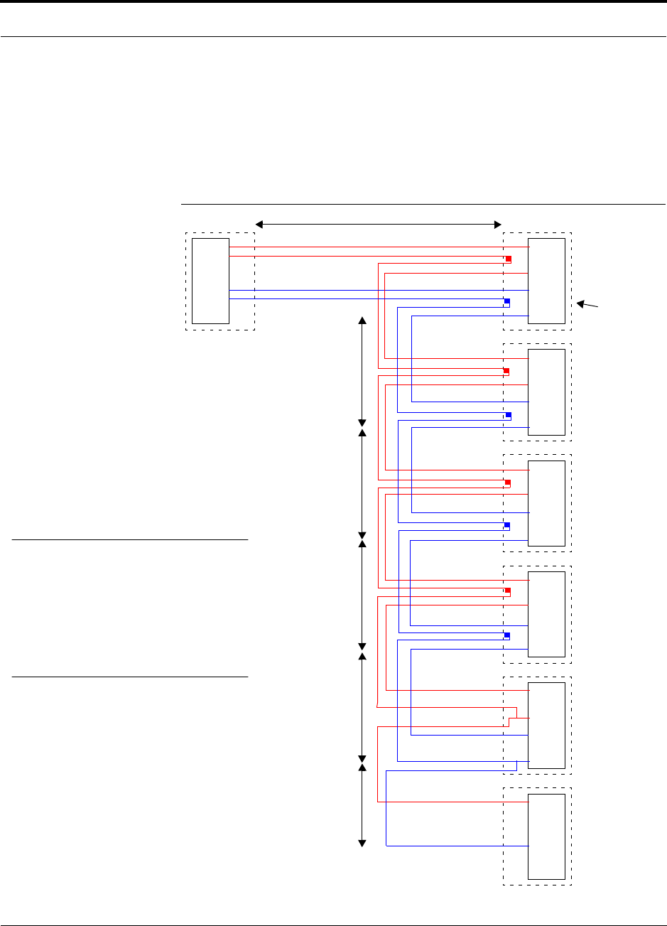
Help Hot Line (U.S. only): 1-800-530-9960 7-55
D-620610-0-20 Rev A
CONFIDENTIAL
Connecting Contact Alarms to a Fusion System
7.7.3 Alarm Cables
5-port Alarm Daisy-Chain Cable
Figure 7-27 shows the 5-port Alarm Daisy-Chain Cable (PN 4024-3), which supports
fault and warning conditions.
Figure 7-27
5-port Alarm Daisy-Chain Cable
DB-9 female to
Base Station,
MetroReach Focus,
or
J1
Female
J2
Male
J3
Male
J4
Male
J5
Male
J6
Male
J7
Female
Terminator
Splice
Splice
Splice
Splice
Splice
Splice
Splice
Splice
7
9
4
5
7
9
4
5
7
9
4
5
7
9
4
5
7
9
4
5
7
4
1.2 meters (4 feet)
.5 meter
(1.5 feet)
DB-9 male to Fusion,
Unison, MetroReach
Focus, Alarm Port
DB-9 male to Fusion,
Unison, MetroReach
Focus Alarm Port
DB-9 male to Fusion,
Unison, MetroReach
Focus Alarm Port
DB-9 male to Fusion,
Unison, MetroReach
Focus Alarm Port
Option 1: DB-9 to Fusion,
Unison, MetroReach
Focus
Alarm Port.
J7 not used
Option 2: Use J2-J5
for alarm ports. J6 is used
to connect to an additional
Alarm Daisy-Chain Cable.
J7 is not used.
Option 3: Connect
fewer than 5 ports and
terminate the daisy chain
by connecting J7 to the
lowest unused port.
Connector
Hood
.5 meter
(1.5 feet)
.5 meter
(1.5 feet)
.5 meter
(1.5 feet)
.25 meter
(.75 feet)
the Alarm Sense
Adapter Cable when
connecting Unison
NOTE: Do not daisy-chain Fusion
Main Hubs with Unison or
MetroReach Focus if you want both
faults and warnings from Fusion. Only
faults are reported if you combine
Fusion with Unison or MetroReach in
the same daisy chain.
7
9
4
5
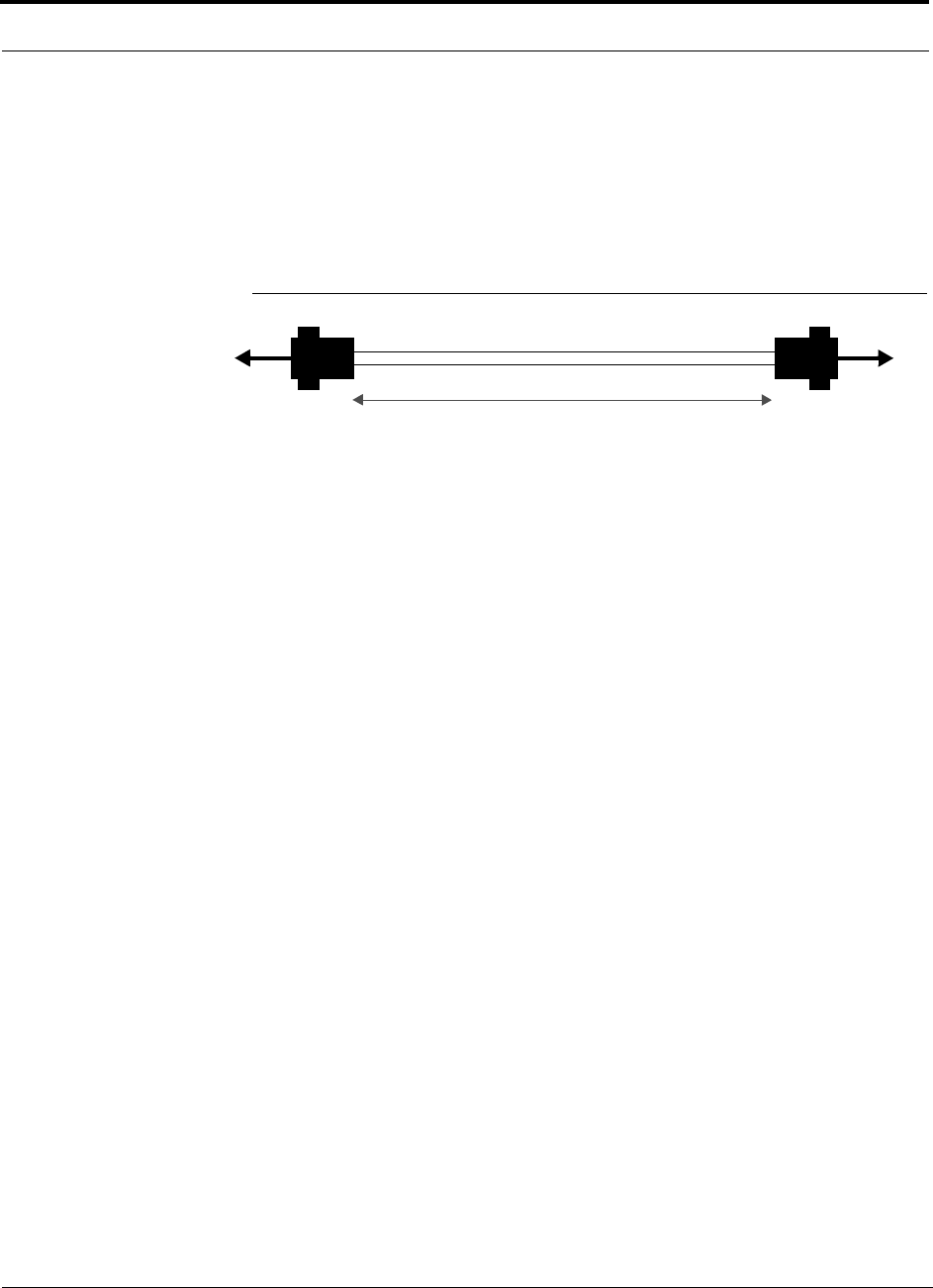
Connecting Contact Alarms to a Fusion System
7-56 InterReach Fusion Installation, Operation, and Reference Manual
CONFIDENTIAL
D-620610-0-20 Rev A
Alarm Sense Adapter Cable
The alarm sense adapter cable (PN 4025-1) translates the Unison fault pinout to the
sense input pins on the Fusion Main Hub. You must use this adapter cable, illustrated
in Figure 7-28, with the 5-port Alarm Daisy-Chain Cable when connecting Unison to
Fusion.
Figure 7-28
Alarm Sense Adapter Cable
J8
1
8
J9
7
9
To Fusion To Daisy-Chain Cable
3 feet
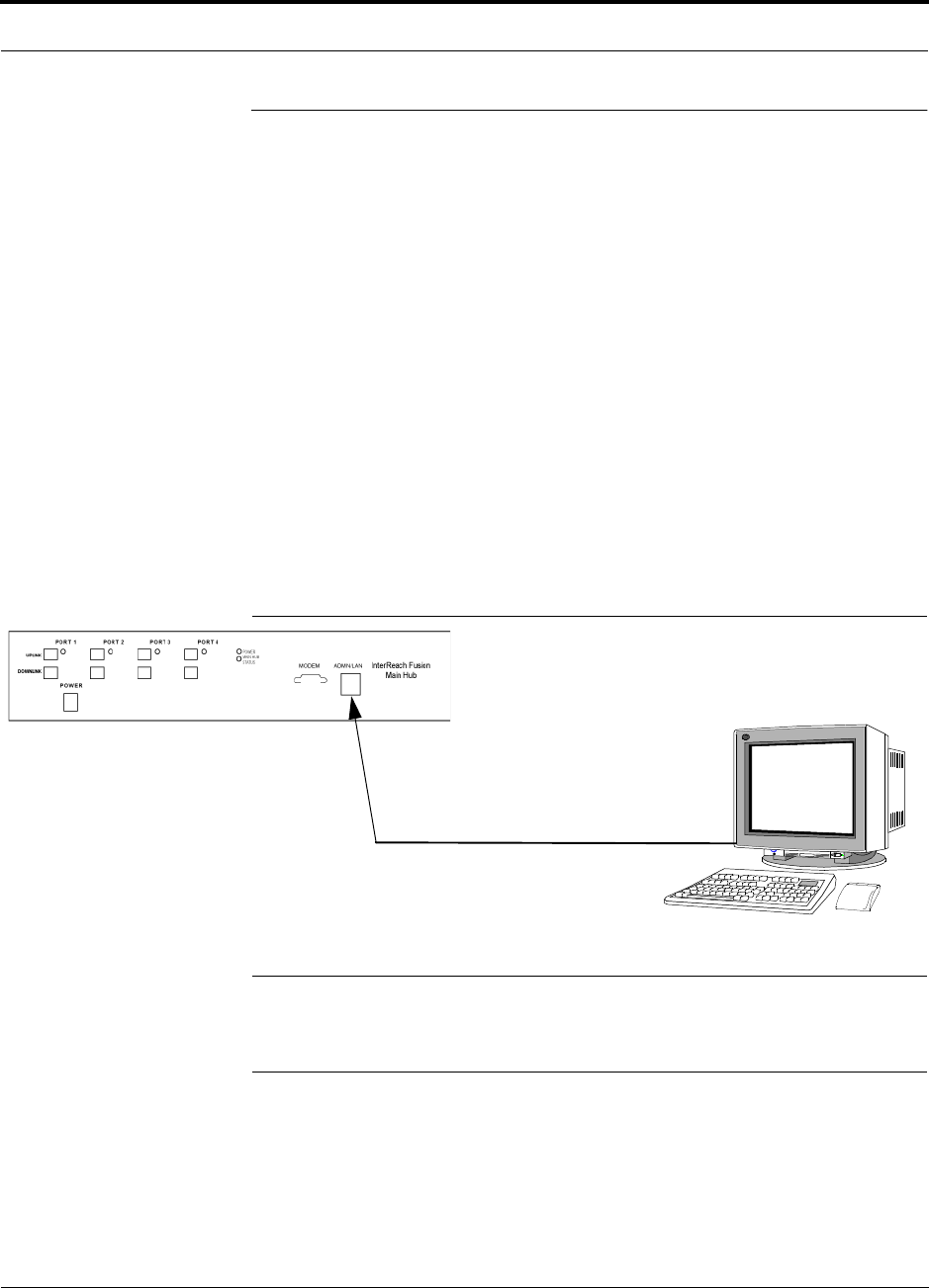
Help Hot Line (U.S. only): 1-800-530-9960 7-57
D-620610-0-20 Rev A
CONFIDENTIAL
Alarm Monitoring Connectivity Options
7.8 Alarm Monitoring Connectivity Options
The following connectivity options are described:
• Section 7.8.1 Direct Connection . . . . . . . . . . . . . . . . . . . . . . . . . . . . . . . . . . . 7-57
• Section 7.8.2 Modem Connection . . . . . . . . . . . . . . . . . . . . . . . . . . . . . . . . . . 7-58
• Section 7.8.3 100 BASE-T Port Expander Connection . . . . . . . . . . . . . . . . . 7-67
• Section 7.8.4 POTS Line Sharing Switch Connection . . . . . . . . . . . . . . . . . . 7-68
• Section 7.8.5 Ethernet LAN Connection . . . . . . . . . . . . . . . . . . . . . . . . . . . . . 7-70
• Section 7.8.6 SNMP Interface . . . . . . . . . . . . . . . . . . . . . . . . . . . . . . . . . . . . . 7-71
Note that the only accessory available through LGC Wireless is the Ethernet
cross-over 100 BASE-T cable, which is provided with AdminBrowser.
7.8.1 Direct Connection
In this configuration, the PC connects directly to the
RJ-45 100 BASE-T
port on the
Fusion Main Hub’s front panel using a cross-over cable.
Figure 7-29
OA&M Direct Connection
NOTE: The cross-over cable provided with the Fusion Main Hub supports
full hardware handshaking, which is required. Refer to Appendix A.4 on
page A-8 for cable wiring information.
PC running
Software
Cross-over 100 BASE-T Cable
Standard Browser
AdminBrower is resident
in Fusion.
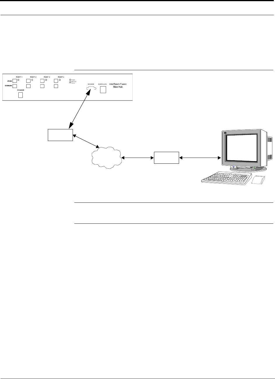
Alarm Monitoring Connectivity Options
7-58 InterReach Fusion Installation, Operation, and Reference Manual
CONFIDENTIAL
D-620610-0-20 Rev A
7.8.2 Modem Connection
In this configuration, the PC and the Fusion Main Hub connect to modems and com-
municate using a standard dial-up telephone connection.
Figure 7-30
OA&M Modem Connection
NOTE: Refer to Appendix A.3 on page A-7 for the modem cable wiring informa-
tion.
Modem switch settings are as follows for US Robotics modem:
• PC-side: 3, 4 and 8 Down (“ON” position)
• Fusion Hub-side: 1, 4 , 5 and 8 Down (“ON” position)
7.8.2.1 Setting Up Fusion Modem Using AdminBrowser
Use the following steps to set up a PPP Dial-In on Fusion:
1.
Start AdminBrowser as explained in the AdminBrowser manual.
2.
Select System Configuration.
3.
Select Setup Modem Connection. The window shown in Figure 7-31 appears.
Straight-through
modem cable
PC running
Software
Standard Browser
Modem
Straight-through modem cable
PSTN
Modem
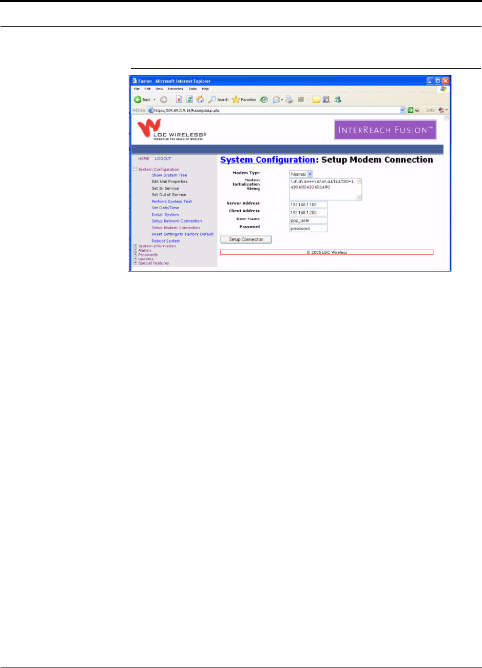
Help Hot Line (U.S. only): 1-800-530-9960 7-59
D-620610-0-20 Rev A
CONFIDENTIAL
Alarm Monitoring Connectivity Options
Figure 7-31
Default Dial-in Settings (Fusion Hub)
4.
Make the desired changes.
5.
Click Setup Connection.
7.8.2.2 Setting Up a PC Modem Using Windows
Use the following sets to set up a dial-up connection on your PC:
1.
Click Start, Settings, Network Connections. The window shown in Figure 7-32
appears.
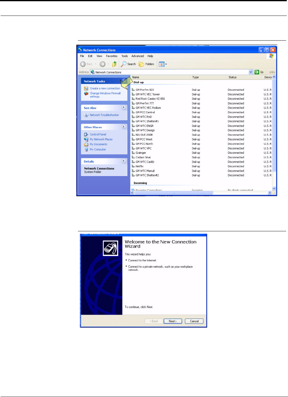
Alarm Monitoring Connectivity Options
7-60 InterReach Fusion Installation, Operation, and Reference Manual
CONFIDENTIAL
D-620610-0-20 Rev A
Figure 7-32
Network Connections Window
2.
Click Create a new connection. The window shown in Figure 7-33 appears.
Figure 7-33
New Connection Wizard - Welcome Window
3.
Click Next. The window shown in Figure 7-34 appears.
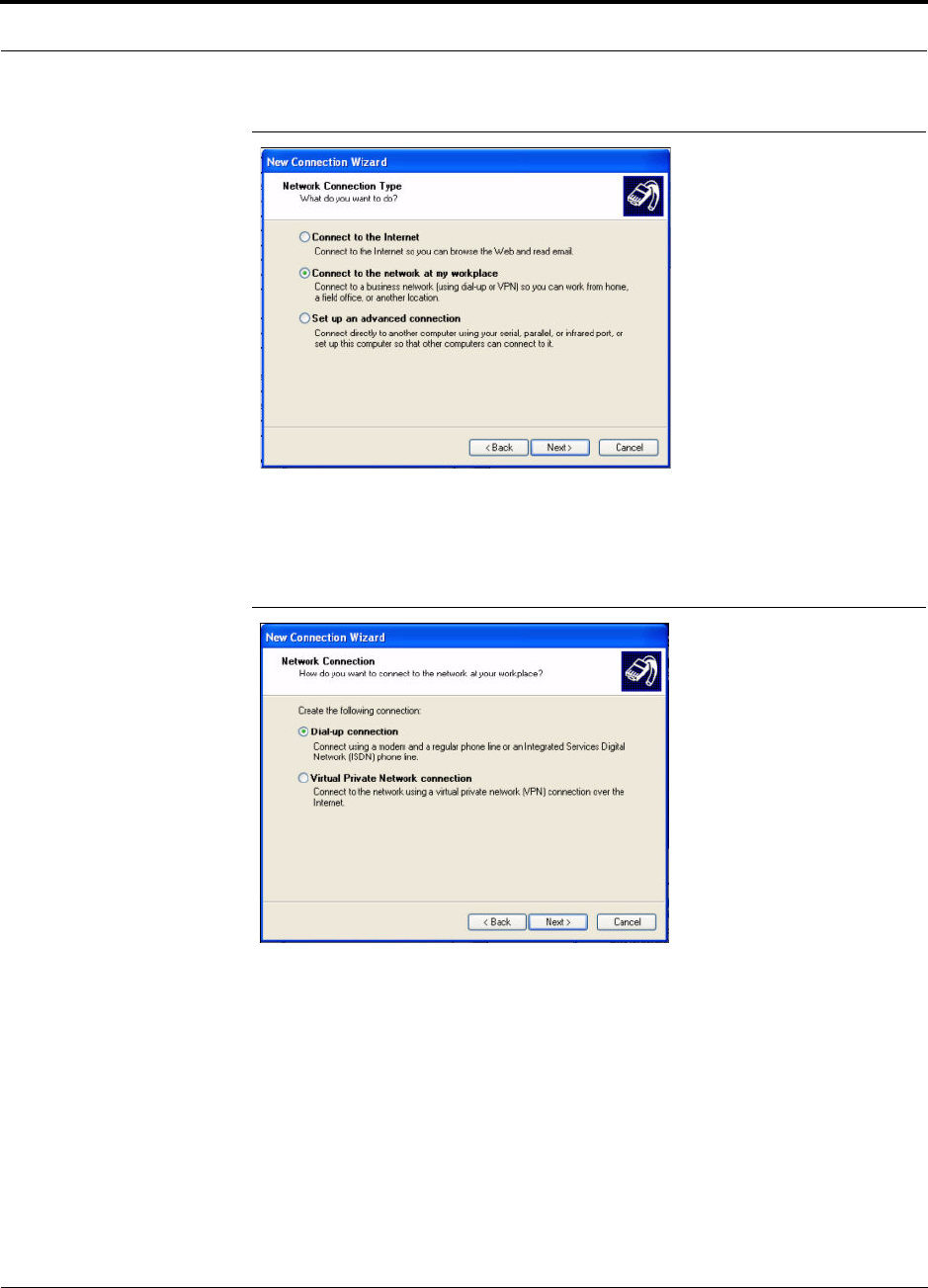
Help Hot Line (U.S. only): 1-800-530-9960 7-61
D-620610-0-20 Rev A
CONFIDENTIAL
Alarm Monitoring Connectivity Options
Figure 7-34
New Connection Wizard - Network Connection Type Window
4.
Select Connect to the network at my workplace and click Next. The window
shown in Figure 7-35 appears.
Figure 7-35
New Connection Wizard - Network Connection Window
5.
Select Dial-up connection and click Next. The window shown in Figure 7-36
appears.
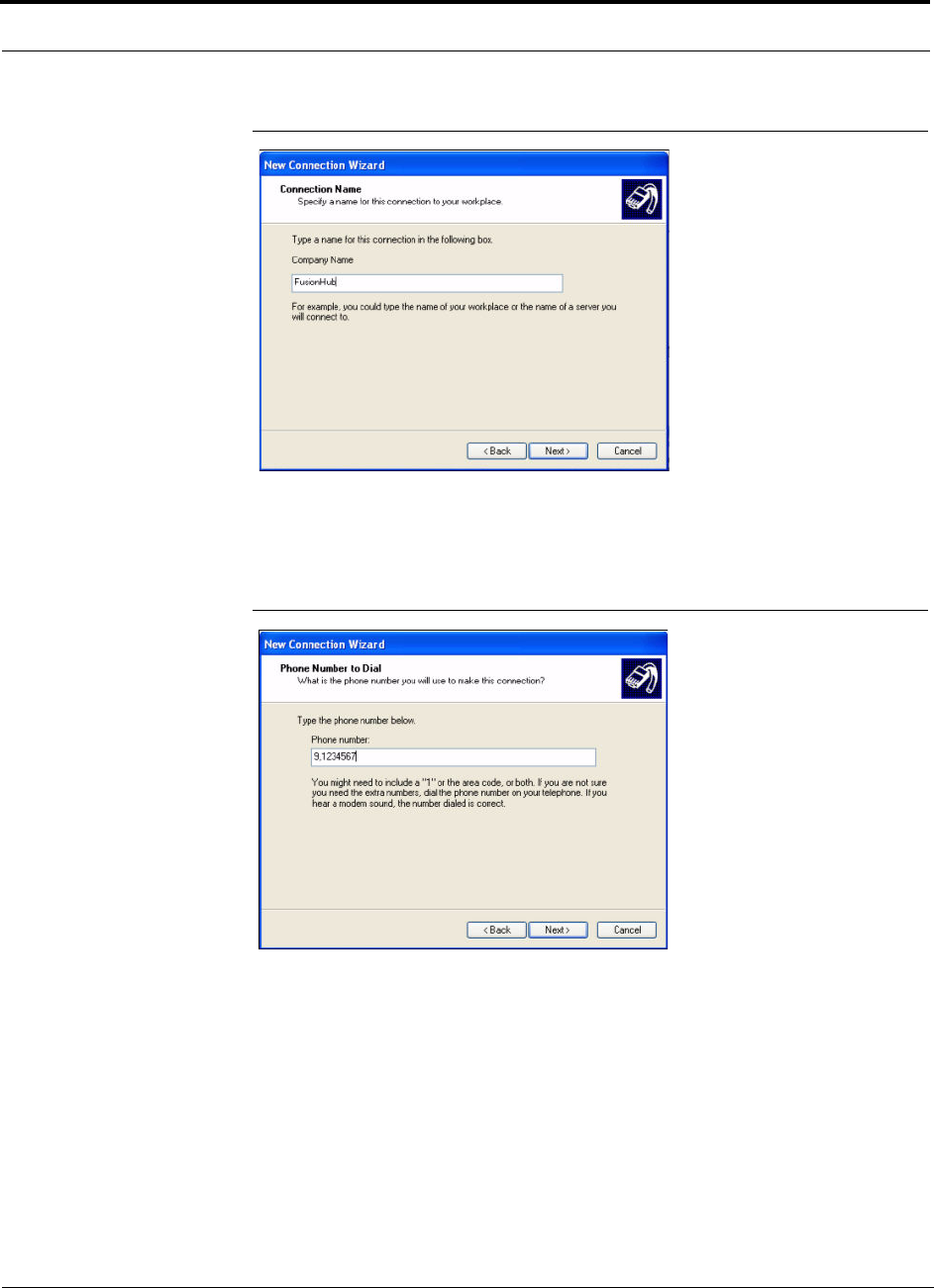
Alarm Monitoring Connectivity Options
7-62 InterReach Fusion Installation, Operation, and Reference Manual
CONFIDENTIAL
D-620610-0-20 Rev A
Figure 7-36
New Connection Wizard - Connection Name Window
6.
Type a name for this connection and click Next. The window shown in
Figure 7-37 appears.
Figure 7-37
New Connection Wizard - Phone Number to Dial Window
7.
Type the desired dial in phone number and click Next. The window shown in
Figure 7-38 appears.
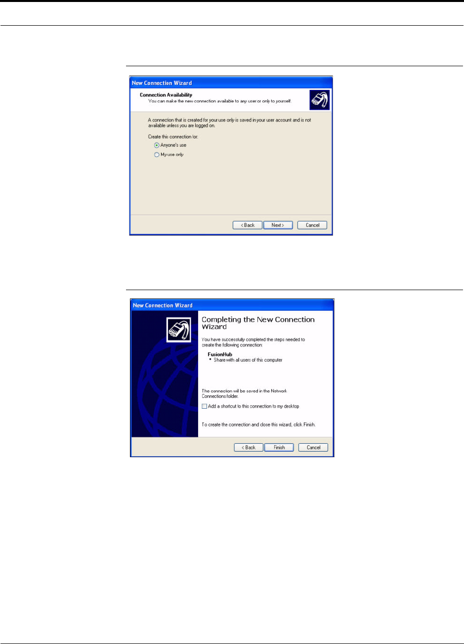
Help Hot Line (U.S. only): 1-800-530-9960 7-63
D-620610-0-20 Rev A
CONFIDENTIAL
Alarm Monitoring Connectivity Options
Figure 7-38
New Connection Wizard - Connection Availability Window
8.
Select Anyone’s use and click Next. The window shown in Figure 7-39 appears.
Figure 7-39
New Connection Wizard - Completing New Connection Window
9.
Click Finish. The window shown in Figure 7-40 appears.
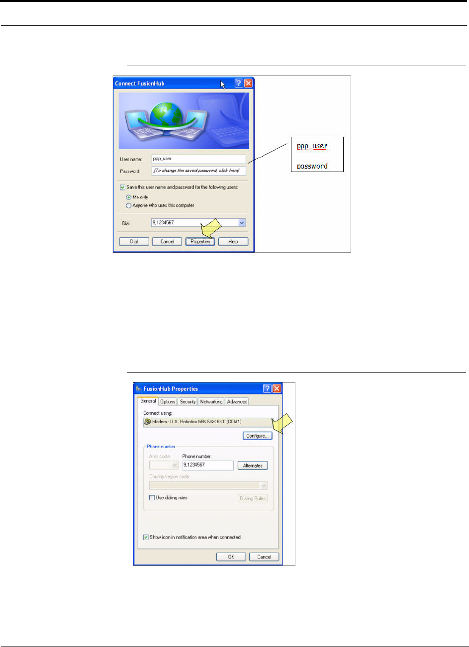
Alarm Monitoring Connectivity Options
7-64 InterReach Fusion Installation, Operation, and Reference Manual
CONFIDENTIAL
D-620610-0-20 Rev A
Figure 7-40
Connect Fusion Hub Window
10.
Type a password as indicated and click Properties. The window shown in
Figure 7-41 appears.
The default parameters are as follows:
• User name: pppuser
• Password (one word, all lower case): password
Figure 7-41
Fusion Hub Properties Window
11.
Click Configure... The window shown in Figure 7-42 appears.
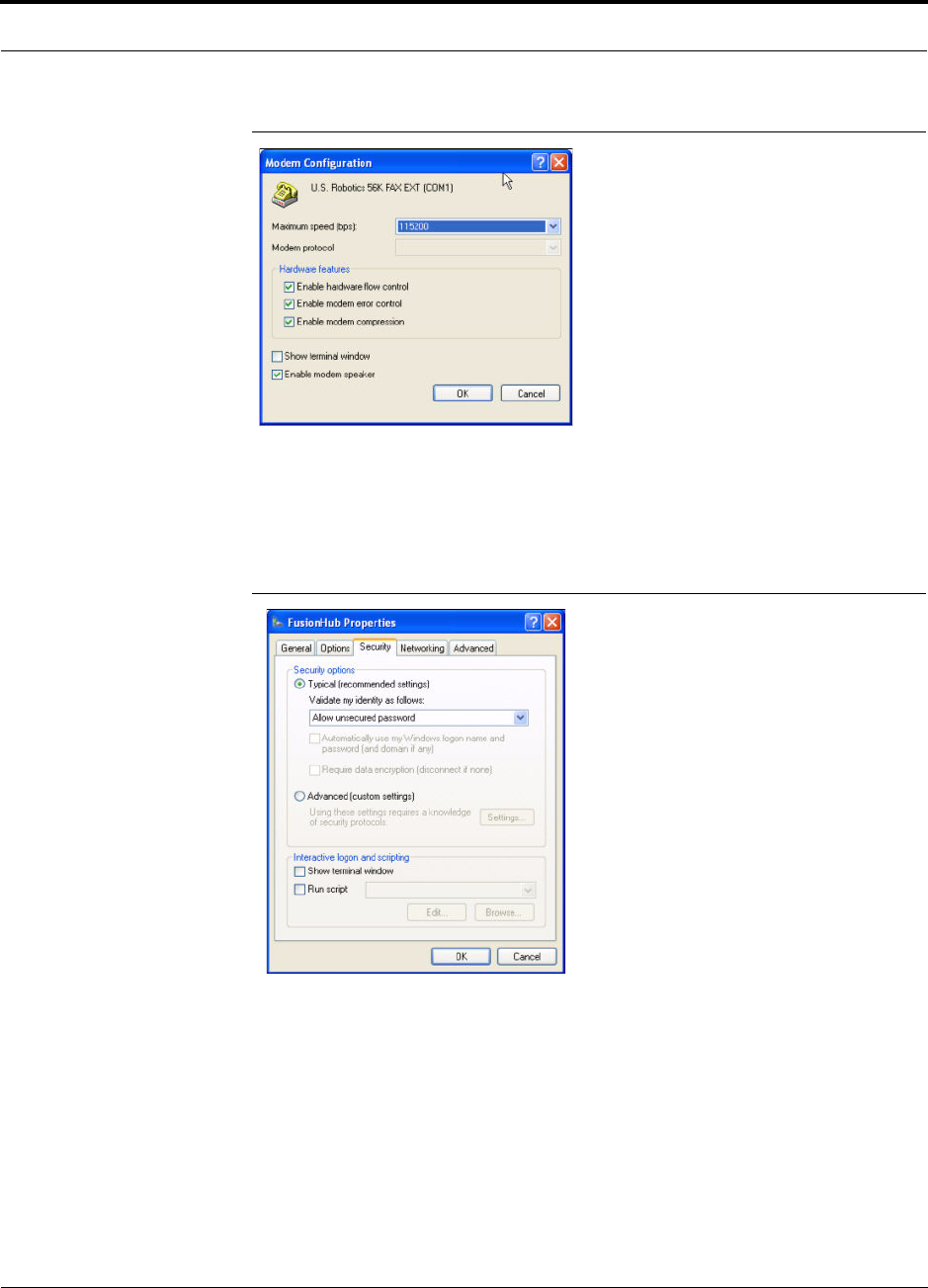
Help Hot Line (U.S. only): 1-800-530-9960 7-65
D-620610-0-20 Rev A
CONFIDENTIAL
Alarm Monitoring Connectivity Options
Figure 7-42
Modem Configuration Window
12.
Select the modem speed and other parameters for your modem as desired and
click OK.
13.
Select the Security tab. The window shown in Figure 7-43 appears.
Figure 7-43
Fusion Hub Properties - Security Tab Window
14.
Select Typical and then click the Networking tab. The window shown in
Figure 7-44 appears.
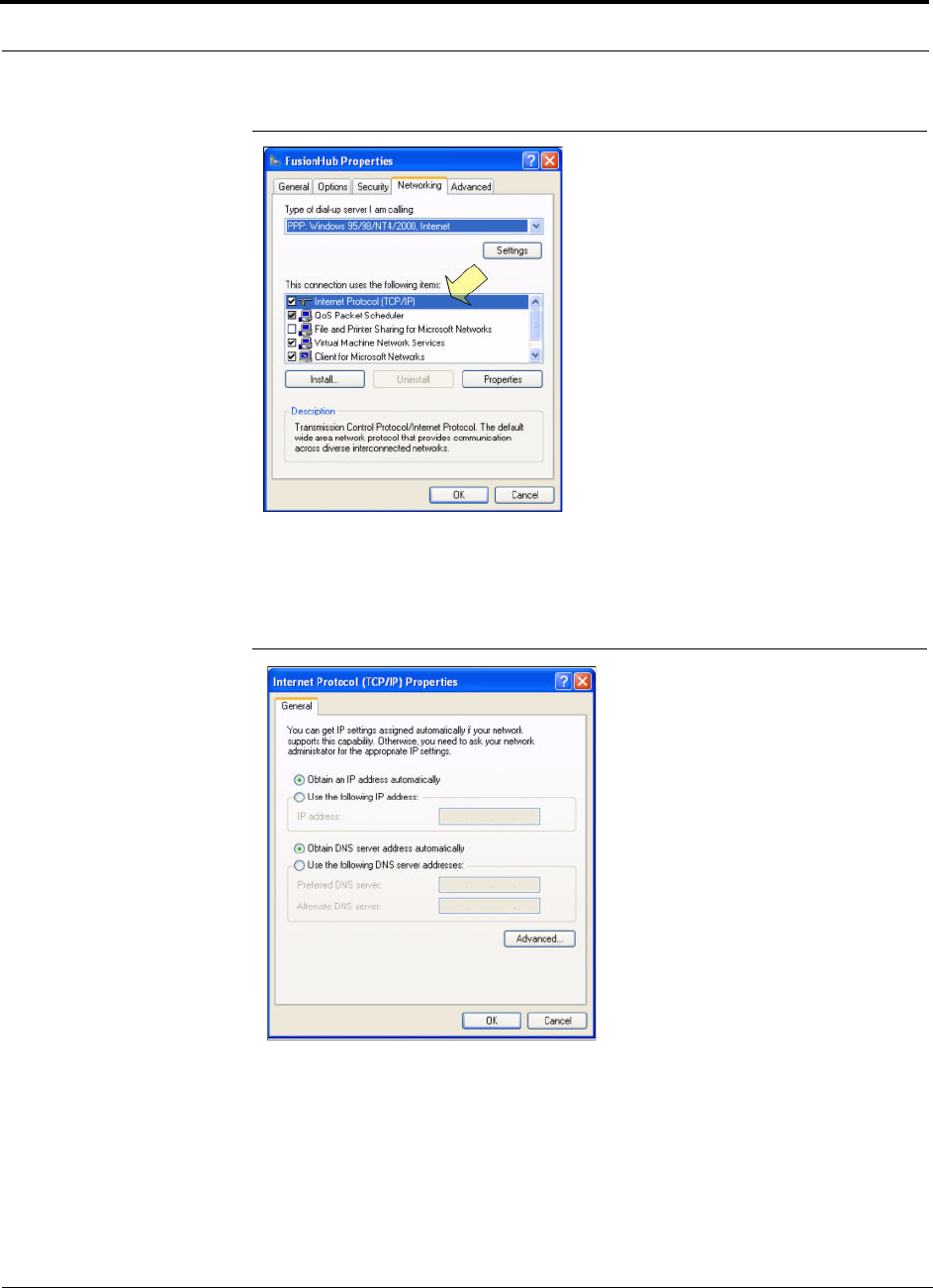
Alarm Monitoring Connectivity Options
7-66 InterReach Fusion Installation, Operation, and Reference Manual
CONFIDENTIAL
D-620610-0-20 Rev A
Figure 7-44
Fusion Hub Properties - Networking Tab Window
15.
Select Internet Protocol (TCP/IP) as shown and click Properties. The window
shown in Figure 7-45 appears.
Figure 7-45
Internet Protocol Properties Window
16.
Select Obtain an IP address automatically and Obtain DNS server address
automatically and click OK.
17.
To connect to the Fusion Hub over the Dial-up connection, start you web browser
and type the server IP address configured in Section 7.8.2.1 in the address bar.
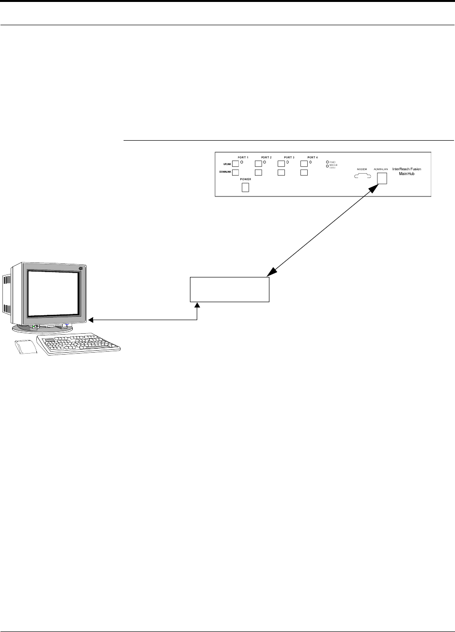
Help Hot Line (U.S. only): 1-800-530-9960 7-67
D-620610-0-20 Rev A
CONFIDENTIAL
Alarm Monitoring Connectivity Options
7.8.3 100 BASE-T Port Expander Connection
In this configuration a LAN switch is used to allow the connection of multiple
devices to a single PC with a 100 BASE-T port. Testing was performed with a Link-
sys 4-port switch. A standard RJ-45 Ethernet cable must be made to connect the LAN
switch to the Fusion Main Hub.
Figure 7-46
OA&M Connection using a 232 Port Expander
LAN switch
100 BASE-T Ethernet connection
RJ-45 male to RJ-45 male
100 BASE-T Cable
PC running
Software
Standard Browser
AdminBrowser software is resident
in Fusion.
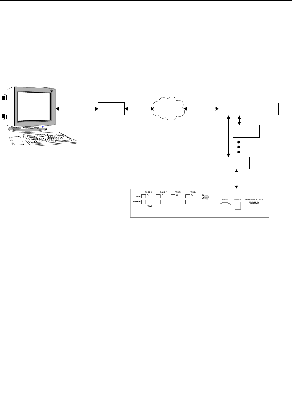
Alarm Monitoring Connectivity Options
7-68 InterReach Fusion Installation, Operation, and Reference Manual
CONFIDENTIAL
D-620610-0-20 Rev A
7.8.4 POTS Line Sharing Switch Connection
Using a line sharing switch, you can connect up to four modems to a single telephone
line. Testing was performed with a Teltone Line Sharing Switch, model number
M-394-B-01.
Figure 7-47
OA&M Connection Using a POTS Line Sharing Switch
Up to 16 modems can be monitored using a single telephone line by cascading line
sharing switches, as shown in Figure 7-48.
Modem
PSTN
Line Sharing Switch
Up to 4 modems
per Switch
Modem
Modem
Straight-through
modem cable
Straight-through
modem cable
PC running
Software
Standard Browser
Standard phone cable
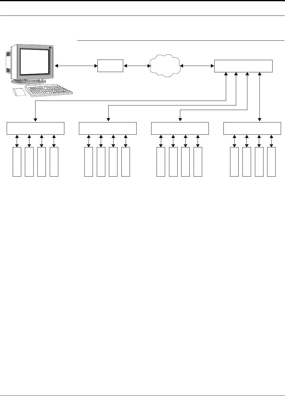
Help Hot Line (U.S. only): 1-800-530-9960 7-69
D-620610-0-20 Rev A
CONFIDENTIAL
Alarm Monitoring Connectivity Options
Figure 7-48
Cascading Line Sharing Switches
Modem
PSTN
Line Sharing Switch
Line Sharing Switch Line Sharing Switch Line Sharing Switch Line Sharing Switch
M
o
d
e
m
M
o
d
e
m
M
o
d
e
m
M
o
d
e
m
M
o
d
e
m
M
o
d
e
m
M
o
d
e
m
M
o
d
e
m
M
o
d
e
m
M
o
d
e
m
M
o
d
e
m
M
o
d
e
m
M
o
d
e
m
M
o
d
e
m
M
o
d
e
m
M
o
d
e
m
Straight-through
modem cable
Straight-
through
modem
cables
PC running
Software
Standard Browser
Standard phone cable
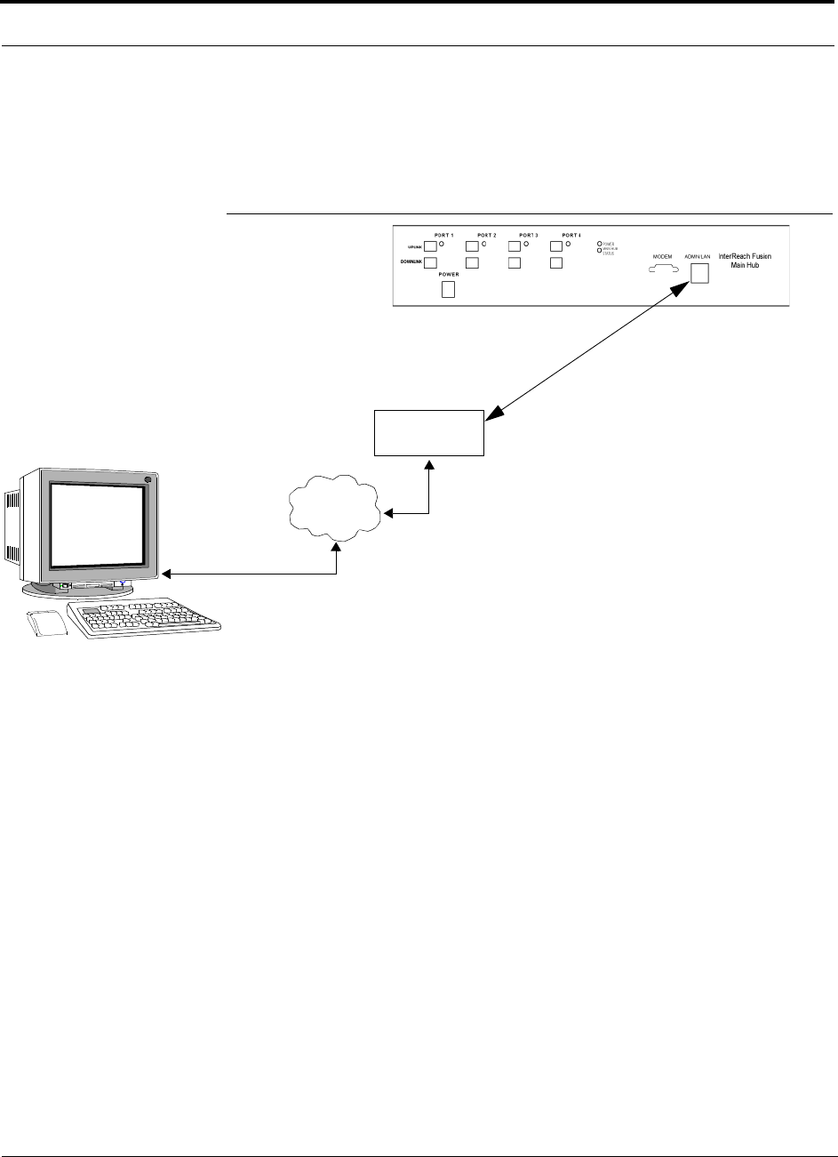
Alarm Monitoring Connectivity Options
7-70 InterReach Fusion Installation, Operation, and Reference Manual
CONFIDENTIAL
D-620610-0-20 Rev A
7.8.5 Ethernet LAN Connection
An Ethernet LAN connection can be used to communicate between the PC and
Fusion. Testing was performed with an Linksys 4-port LAN switch.
Figure 7-49
OA&M Connection Using Ethernet and ENET/232 Serial Hub
LAN
Switch
TCP/IP
Ethernet
100 BASE-T Cable
RJ-45 to RJ-45 male
Ethernet
PC running
Software
Standard Browser
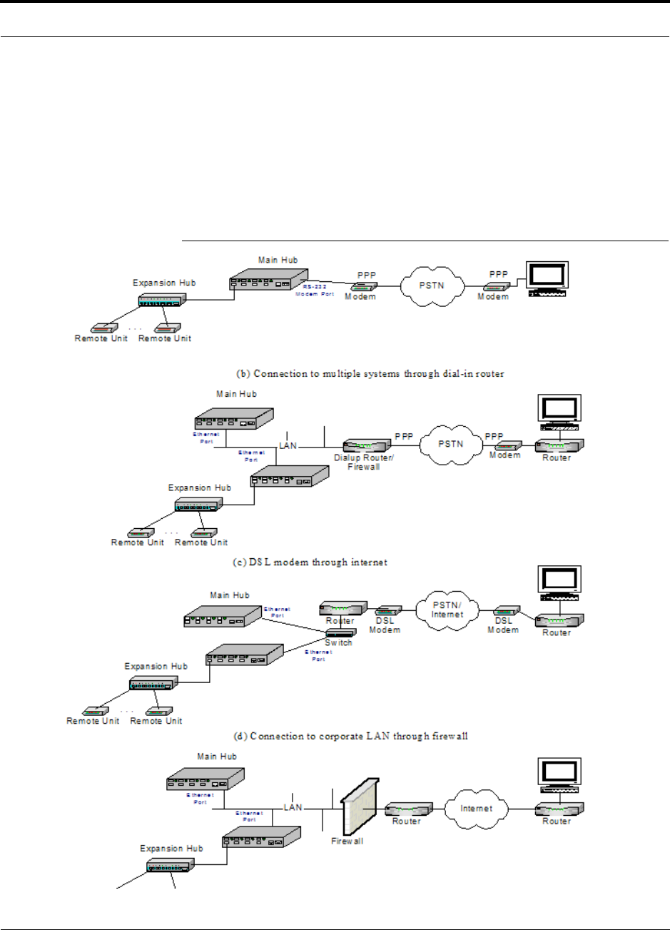
Help Hot Line (U.S. only): 1-800-530-9960 7-71
D-620610-0-20 Rev A
CONFIDENTIAL
Alarm Monitoring Connectivity Options
7.8.6 SNMP Interface
Faults and warnings can also be diagnosed with SNMP using a standard (NMS) net-
work management system (optional). SNMP resident software in Fusion provides
SNMP interactions for Traps and Notification.
The Fusion SNMP includes a MIB for integrating into the Network Management Sys-
tem (NMS) and supports SNMPv1 and SNMPv2c.
Figure 7-50
Fusion SNMP Configuration Options

Alarm Monitoring Connectivity Options
7-72 InterReach Fusion Installation, Operation, and Reference Manual
CONFIDENTIAL
D-620610-0-20 Rev A

InterReach Fusion Installation, Operation, and Reference Manual 8-1
D-x620610-0-20 Rev A
CONFIDENTIAL
SECTION 8
Replacing Fusion Components
This section contains the following subsections:
• Section 8.1 Replacing an RAU . . . . . . . . . . . . . . . . . . . . . . . . . . . . . . . . . . . . 8-1
• Section 8.2 Replacing a Fusion Expansion Hub . . . . . . . . . . . . . . . . . . . . . . . 8-3
• Section 8.3 Replacing a Fusion Main Hub . . . . . . . . . . . . . . . . . . . . . . . . . . . 8-4
8.1 Replacing an RAU
Be aware that the new RAU must support the same bands as the one you are replac-
ing. If the RAU is of the wrong band combination, it will not operate properly in the
system.
Replacing an RAU
1.
Using AdminBrowser, log in and click
S
YSTEM
I
NFORMATION
.
2.
Click
S
HOW
S
YSTEM
T
REE
, select Fusion Main Hub, and click
G
ET
S
YSTEM
I
NFOR
-
MATION
.
All system settings for Hubs and RAUs will be displayed. Write down or save the
Uplink and Downlink Attenuation setting so you can set the new RAU with the
same settings.
3.
Click
C
ANCEL
to close the window.
4.
Verify that the new RAU is of the same frequency bands as the one replaced.
5.
Disconnect the CATV cable and antenna cable from the unit to be replaced.
6.
Install the new RAU.
7.
Connect the antenna cable and then the CATV cable to the new RAU.
8.
Click
S
YSTEM
C
ONFIGURATION
.
9.
Click
S
HOW
S
YSTEM
T
REE
.
10.
Select the Fusion RAU replaced and click
E
DIT
U
NIT
P
ROPERTIES
.

Replacing an RAU
8-2 InterReach Fusion Installation, Operation, and Reference Manual
CONFIDENTIAL
D-x620610-0-20 Rev A
11.
Set the attenuation of each band as the old RAU was programmed and click
S
AVE
P
ROPERTIES
.
Perform System Test
When convenient, perform System Test to optimize performance.
During System Test, the entire system is temporarily off-line and no RF is
being transmitted.
Checking the RAU’s LEDs
1.
The RAU’s
LINK
and
ALARM
LEDs should blink (green/red) on power up.
• If the LEDs do not blink on power up, replace the RAU.
2.
After several seconds both LEDs should change to green, which indicates that the
unit has been successfully replaced, there is communication with the Hub, and the
RAU band is correct.
a.
If the
LINK
LED remains green and the
ALARM
LED remains red, verify that
the RAU model is correct for the intended frequency band.
– Disconnect the cable and then reconnect it once; doing this more than once
will not change the result.
b.
If both LEDs still don’t change to green, use AdminBrowser to determine the
exact nature of the fault and see a recommendation of how to correct it.
c.
If both LEDs turn red (after 90 seconds), the Hub has terminated communica-
tions.

Help Hot Line (U.S. only): 1-800-530-9960 8-3
D-x620610-0-20 Rev A
CONFIDENTIAL
Replacing a Fusion Expansion Hub
8.2 Replacing a Fusion Expansion Hub
Replacing a Fusion Expansion Hub
1.
Turn off the power to the Expansion Hub.
2.
Disconnect all CATV cables, both fiber cables, and the AC power cord.
3.
Replace the Expansion Hub with a new one.
4.
Connect the AC power cord, all CATV cables, and both fiber cables – remember-
ing to clean and correctly connect the uplink and downlink fiber.
5.
Turn on the power to the Expansion Hub.
AdminBrowser Tasks
• The Main Hub automatically issues the band setting.
• When convenient, use AdminBrowser to perform System Test in order to optimize
performance.
During System Test, the entire system is temporarily off-line and no RF is
being transmitted. For a fully loaded system (one Main Hub, four Expansion
Hubs, and 32 RAUs), it can take up to 1.5 minutes to complete the test.
Checking the Expansion Hub’s LEDs
• The LEDs should blink through all states on power up.
• If the LEDs do not blink on power up, replace the Expansion Hub.
• If the LEDs do not illuminate at all, make sure the AC power cable is con-
nected.
• The
UL STATUS
and
DL STATUS
LEDs should be green.
• The
E-HUB STATUS
and
POWER
LEDs should be green.
• For each CATV port that has an RAU connected the LEDs should be green.
It can take several seconds for each CATV connection for the LEDs to display
properly.
NOTE: Refer to Section 9 for troubleshooting using the LEDs.

Replacing a Fusion Main Hub
8-4 InterReach Fusion Installation, Operation, and Reference Manual
CONFIDENTIAL
D-x620610-0-20 Rev A
8.3 Replacing a Fusion Main Hub
You must record the system configuration settings from the old Fusion Main Hub’s
memory before replacing the unit. You will program the new Main Hub with this
information. If the Main Hub is programmed incorrectly, the system will not work. If
the Hub to be replaced is not functioning and you cannot use AdminBrowser, get the
configuration settings from the As-Built Document that was created as part of the
original installation.
Replacing a Fusion Main Hub
1.
Using AdminBrowser, log in, click
S
YSTEM
I
NFORMATION
, click
S
HOW
S
YSTEM
T
REE
, select Fusion Hub, click
G
ET
S
YSTEM
I
NFORMATION
.
2.
Turn off the power to the Fusion Main Hub.
3.
Disconnect all cables and the AC power cord.
4.
Replace the Main Hub with a new one.
5.
Connect the AC power cord and all cables.
6.
Connect the crossover Ethernet cable to the PC and then to the Main Hub’s front
panel 100Base-T connector. ADMIN/LAN port)
7.
Start the standard browser on the PC to communicate with AdminBrowser soft-
ware.
8.
Turn on the power to the Main Hub.
9.
Observe the LEDs after turning on the power.
All the LEDs blink during the initial power up sequence. All LEDs should turn
green after the power on sequence is complete. Power up sequence takes between
1 and 2 minutes depending on the number of RAUs.
Configure the New Fusion Main Hub
1.
Using AdminBrowser and log in to the Main Hub.
2.
Click
S
YSTEM
C
ONFIGURATION
.
3.
Click
S
ET
D
ATE
/T
IME
and enter the current date and time.
4.
Click
S
ET
D
ATE
/T
IME
.
5.
Follow the instructions to eventually reboot the system to set the date and time.
6.
Using AdminBrowser, log in and click
S
YSTEM
C
ONFIGURATION
.
7.
Click
I
NSTALL
S
YSTEM
.
8.
Set the new Main Hub parameters from the old Main Hub and click
I
NSTALL
S
YS
-
TEM
(that is, uplink and downlink gain, system labels, and so on).
9.
Follow the instructions to perform a System Test.

Help Hot Line (U.S. only): 1-800-530-9960 8-5
D-x620610-0-20 Rev A
CONFIDENTIAL
Replacing a Fusion Main Hub
10.
Click
S
YSTEM
C
ONFIGURATION
and click on
S
ETUP
N
ETWORK
C
ONNECTION
OR
M
ODEM
C
ONNECTION
if the Main Hub has Network or Modem equipment con-
nected to it.
During System Test, the entire system is temporarily off-line and no RF is
being transmitted.
Checking the Main Hub’s LEDs
• The LEDs should blink through a 5-second test on power up.
• If the LEDs do not blink on power up, replace the Main Hub.
• If the LEDs do not illuminate at all, make sure the AC power cable is con-
nected.
• For each fiber optic port that has a connected Expansion Hub, which has been pro-
grammed with a band, the
PORT
LED should be green.
• Refer to Section 9.3, “Troubleshooting,” on page 9-3 for more LED states.
NOTE: If there is no communication between the Main Hub and the Expansion
Hubs, use the AdminBrowser to isolate system problems.

Replacing a Fusion Main Hub
8-6 InterReach Fusion Installation, Operation, and Reference Manual
CONFIDENTIAL
D-x620610-0-20 Rev A

InterReach Fusion Installation, Operation, and Reference Manual 9-1
D-620610-0-20 Rev A
CONFIDENTIAL
SECTION 9
Maintenance, Troubleshooting,
and Technical Assistance
This section contains the following subsections:
• Section 9.1 Service . . . . . . . . . . . . . . . . . . . . . . . . . . . . . . . . . . . . . . . . . . . . . 9-1
• Section 9.2 Maintenance . . . . . . . . . . . . . . . . . . . . . . . . . . . . . . . . . . . . . . . . . 9-2
• Section 9.3 Troubleshooting . . . . . . . . . . . . . . . . . . . . . . . . . . . . . . . . . . . . . . 9-3
• Section 9.4 Troubleshooting CATV . . . . . . . . . . . . . . . . . . . . . . . . . . . . . . . 9-10
• Section 9.5 Technical Assistance . . . . . . . . . . . . . . . . . . . . . . . . . . . . . . . . . 9-10
9.1 Service
There are no user-serviceable parts in any of the Fusion components. Faulty or failed
components are fully replaceable through LGC Wireless. All units should be replaced
and returned to the factory for service if needed.
Address 2540 Junction Avenue
San Jose, California
95134-1902 USA
Phone 1-408-952-2400
Fax 1-408-952-2410
Help Hot Line 1-800-530-9960 (U.S. only)
+1-408-952-2400 (International)
Web Address http://www.lgcwireless.com
e-mail lgccustomersupport@lgcwireless.com

Maintenance
9-2 InterReach Fusion Installation, Operation, and Reference Manual
CONFIDENTIAL
D-620610-0-20 Rev A
9.2 Maintenance
Keep the fiber ports clean and free of dust. No other periodic maintenance of the
Fusion equipment is required.
To clean the fiber ports:
You can clean the Hub’s fiber ports using canned compressed air or isopropyl alcohol
and cotton swabs.
Considerations:
• If you use compressed air:
• The air must be free of dust, water, and oil.
• Hold the can level during use.
• If using isopropyl alcohol and foam-tipped swab:
• Use only 98% pure or more alcohol.
Procedure using compressed air:
1.
Remove the connector’s dust cap.
2.
Spray the compressed air away from the unit for a few seconds to clean out the
nozzle and then blow dust particles out of each fiber port.
Procedure using isopropyl alcohol:
1.
Remove the connector’s dust cap.
2.
Dip a 2.5mm lint-free, foam-tipped swab in isopropyl alcohol and slowly insert
the tip into the connector.
3.
Gently twist the swab to clean the connector.
4.
Insert a dry swab to dry the connector.
Additionally, you can use compressed air after the alcohol has completely evapo-
rated.

Help Hot Line (U.S. only): 1-800-530-9960 9-3
D-620610-0-20 Rev A
CONFIDENTIAL
Troubleshooting
9.3 Troubleshooting
NOTE: Fusion has no user-serviceable parts. Faulty or failed units are fully
replaceable through LGC Wireless.
Sources of potential problems include:
• Faulty cabling/connector
• Malfunction of one or more Fusion components
• Antenna, base station, or repeater problem
• External RF interface
• Tripped circuit breaker
• Equipment is not grounded
• Using an Ethernet crossover cable that does not support full hardware handshaking
when using AdminBrowser
NOTE: Faulty cabling is the cause of a vast majority of problems. All CATV 75
Ohm cable should be tested to TIA-570-B specifications. The RAU will be damaged
if the cable connector is not installed properly.
You must use AdminBrowser for troubleshooting the system, use the LEDs only as
backup or for confirmation.
If you cannot determine the cause of a problem after following the recommended pro-
cedures, call LGC Wireless customer help hot line:
1-800-530-9960 (U.S. only)
+1-408-952-2400 (International)
Or, email us at lgccustomersupport@lgcwireless.com.
Please provide the following information:
• Serial number of the unit
• Description of the problem
• Using AdminBrowser 1.00, access Special Features, then the Get Service
Information window. Save and email this file to LGC Wireless.
• What is the length of the CATV cable? What type is it (for example RG-6)?
• Status of the LEDs on the unit
• Was the unit power cycled?

Troubleshooting
9-4 InterReach Fusion Installation, Operation, and Reference Manual
CONFIDENTIAL
D-620610-0-20 Rev A
9.3.1 Troubleshooting Using AdminBrowser
Use AdminBrowser software to determine the current faults and warnings for all of
the units in the system. To troubleshoot, start with the Fusion Main Hub’s faults AND
warnings, then proceed to each of the Expansion Hubs, finishing with each of the
RAUs.
NOTE: AdminBrowser v1.00 displays events (faults, warnings, or status
messages) depending on your view preference. To change your view prefer-
ence, refer to Section 3.3.2, “View Preference,” on page 3-10.
System Troubleshooting
Using AdminBrowser, click
S
YSTEM
I
NFORMATION
, then click
G
ET
F
AULTS
, W
ARNINGS
AND
S
TATUSES
. This gives the present status of the system, depending upon View
Preferences for all components.
Faults usually impact service; warnings may impact service; status messages contain
information that should not be ignored, but indicate conditions that do not generally
impact service.
NOTE: System commands can take longer to execute compared to compo-
nent commands.
NOTE: This RAU icon indicates there is fault on the RAU. This icon
indicates a disconnected device. You cannot request status on a discon-
nected device.
9.3.1.1 Troubleshooting Recommendations
Some actions that you can take, depending on the device fault or warning include, are
as follows:
a.
Hardware faults on Expansion Hub.
– Try swapping fiber with another Expansion Hub at the Main Hub.
– Try cleaning the fiber and the fiber ports with alcohol foam tip swab and
compressed air. See Section , “To clean the fiber ports:,” on page -2.
– Power cycle the Expansion Hub.
b.
Under Alarms, click
C
LEAR
A
LL
D
ISCONNECTS
at the Fusion Main Hub.

Help Hot Line (U.S. only): 1-800-530-9960 9-5
D-620610-0-20 Rev A
CONFIDENTIAL
Troubleshooting
c.
Power cycle the Fusion Main Hub.
d.
RAU hardware faults. Try moving a working CATV to the suspect port and
verifying that the RAU comes up OK.
e.
Try isolating the system components:
– Check to see if the whole system is effected or a portion of the system.
– If the whole system is effected, disconnect the DAS system from the RF
source and see if the RF source is working.
– Continue to isolate by disabling portions of the system. Under System Con-
figuration, click
S
HOW
S
YSTEM
T
REE
and select a component. Then click
S
ET
O
UT
OF
S
ERVICE
/S
ET
IN
S
ERVICE
.
9.3.1.2 Fault/Warning/Status Indications
Once all of the units are powered on and the cable connections are made, the faults
from each unit can be requested using AdminBrowser. Start with the Fusion Main
Hub and work downstream.
Resolve all faults first and then check the warnings. Take appropriate action to
resolve the faults, as indicated in the following tables. In cases where there is more
than one possible cause, they are listed from the “most likely” to the “least likely”
cause. Actions are listed in the order that they should be performed; not all actions
may need to be done.
NOTE: If you have a red
STATUS
LED without a fault message, it probably
indicates that the unit is locked out.
Refer to Appendix C for tables containing Fault, Warning, and Status messages and
their meanings.
9.3.2 Troubleshooting Using LEDs
The following troubleshooting guide is from the perspective that all Fusion equip-
ment is installed, their cables are connected, and they are powered on; it is assumed
that the system was operating normally before the problem to be diagnosed occurred.
Always use AdminBrowser, if possible, to troubleshoot the system. The Fusion Main
Hub and Expansion Hub LEDs are for backup troubleshooting. The RAU LEDs prob-
ably will not provide additional information for troubleshooting.

Troubleshooting
9-6 InterReach Fusion Installation, Operation, and Reference Manual
CONFIDENTIAL
D-620610-0-20 Rev A
9.3.2.1 Troubleshooting Main Hub LEDs During Normal Operation
All of the Main Hub’s LEDs should be green during normal operation. If any LEDs
are red, get status using AdminBrowser to determine the exact cause and recommen-
dations.
Table 9-1
Troubleshooting Main Hub Port LEDs During Normal Operation
During
Normal
Operation
Main Hub
Port LEDs State Action Impact
Expansion
Hub Not
Connected
PORT
Red If the Expansion Hub was discon-
nected accidentally, re-connect the
cables. The LEDs should change to
Green/Red (then Green/Green, after
20 seconds, if the Main Hub band
has been programmed).
When the Expansion Hub is to be
removed from service permanently,
use AdminBrowser’s ‘Clear All Dis-
connect Status’ command to clear all
disconnect states to no connect
states.
The Expansion Hub was previously
connected, but it is not currently con-
nected; the Expansion Hub uplink
cable disconnected.
AdminBrowser clears all disconnects
caused by installation as part of the
clean-up process. After installation,
power cycle the Main Hub or use
AdminBrowser’s “Clear All Discon-
nect Status” command.
Changes the Main Hub’s port LEDs to
Off/Off.
Expansion
Hub
Connected
PORT
Red 60
ppm)
Use AdminBrowser to determine the
exact cause of the Main Hub’s faults.
Lost communication with Expansion
Hub; could be Expansion Hub problem
or fiber cable problem.
The Expansion Hub communication
problems delay MH responses to
AdminBrowser commands, resulting in
command time-outs. You can discon-
nect the offending Expansion Hub ini-
tially to obtain status from the rest of
the system, then connect the Expansion
Hub and resolve the communication
problem.
PORT
Red The Expansion Hub or connected
RAU reports a fault condition; use
AdminBrowser to determine the
exact cause of the Expansion Hub
and RAU’s faults.
Degraded performance or unit may be
off-line.
Depends on fault condition.

Help Hot Line (U.S. only): 1-800-530-9960 9-7
D-620610-0-20 Rev A
CONFIDENTIAL
Troubleshooting
Table 9-2
Troubleshooting Main Hub Status LEDs During Normal Operation
During
Normal
Operation
Main Hub
Status
LEDs State Action Impact
At Any
Time
MAIN HUB
STATUS
Red Use AdminBrowser to determine the
exact cause of the fault.
Power cycle one time. If the fault
remains, replace the Main Hub.
Internal Main Hub fault.
Use AdminBrowser to check if the
Main Hub is commanded
Out-of-Service (every Expansion
Hub port status LED will be red as
well).
A power cycle will not clear a com-
manded Out-of-Service, you must
use AdminBrowser to clear this
state.
The Main Hub and all downstream
units are off-line.
MAIN HUB
STATUS
Flashing
Red
(60ppm(
Reduce input signal power. Signal compression.
At Any
Time
POWER
Red Replace the Main Hub. One or more power supplies are out of
specification.

Troubleshooting
9-8 InterReach Fusion Installation, Operation, and Reference Manual
CONFIDENTIAL
D-620610-0-20 Rev A
9.3.2.2 Troubleshooting Expansion Hub LEDs During Normal Operation
• All of the Expansion Hub
LINK
and
E-HUB/RAU
LEDs that have RAUs connected
should be Green/Green, indicating that the RAU is powered on, communication is
established, and operation is normal.
• The
POWER
,
EHUB STATUS
,
DL STATUS
, and
UL STATUS
LEDs should all be Green.
Table 9-3
Troubleshooting Expansion Hub Port LEDs During Normal
Operation
During
Normal
Operation
Expansion
Hub Port
LEDs State Action Impact
RAU is not
connected
PORT
Off If the RAU was disconnected acci-
dentally, re-connect the CATV
cable. The Expansion Hub’s port
LEDs should change to Green/Red
(then Green/Green, after 20 sec-
onds, if the Main Hub is connected,
powered on, and has band pro-
grammed).
Use AdminBrowser’s “Clear All
Disconnect Status” command if
you are permanently removing the
RAU from service. The Expansion
Hub’s port LEDs should change to
Off/Off.
The RAU was previously connected,
but it is not currently connected; the
RAU cable is disconnected.
RAU is
connected
PORT
Red Disconnect/reconnect the CATV
cable to force power-on reset to the
RAU. If the port LEDs remain Red
check for the exact cause of Expan-
sion Hub faults using Admin-
Browser.
Lost communications with the RAU.
The RAU could have powered down
due to over current; cable could have
been damaged.
PORT
Flashing
Red (60
ppm)
The RAU reports a fault condition;
check for the exact cause of Expan-
sion Hub and RAU faults using
AdminBrowser.
Depends on the fault condition.
PORT
Flashing
Red (60
ppm)
The Expansion Hub reports no con-
nection, cable shorts, or a current
port trap condition.
Expansion Hub communications with
the RAU. The Expansion Hub is at
fault. The cable could have been dam-
aged. The cable leads may be shorted.

Help Hot Line (U.S. only): 1-800-530-9960 9-9
D-620610-0-20 Rev A
CONFIDENTIAL
Troubleshooting
Table 9-4
Troubleshooting Expansion Hub Status LEDs During Normal
Operation
During
Normal
Operation
Expansion
Hub
Status
LEDs State Action Impact
At Any Time
UL STATUS
Red Check uplink fiber for optical loss.
Power cycle Expansion Hub one
time to check uplink laser.
No communications between the Main
Hub and the Expansion Hub.
Uplink laser failure.
DL STATUS
Red Check the downlink fiber for opti-
cal loss
No communications with the Main Hub.
E-H
STATUS
Red If either the
UL STATUS
or the
DL
STATUS
are also red, see above.
Cycle power on the Expansion
Hub. If fault remains, replace the
Expansion Hub.
Internal Expansion Hub fault (including
either of the above
UL STATUS
or
DL
STATUS
states).
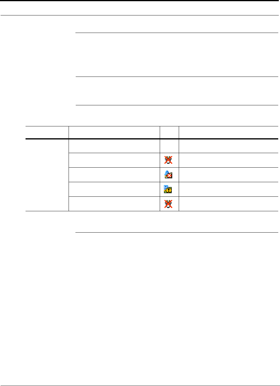
Troubleshooting CATV
9-10 InterReach Fusion Installation, Operation, and Reference Manual
CONFIDENTIAL
D-620610-0-20 Rev A
9.4 Troubleshooting CATV
The following table summarizes CATV problems, as reported by AdminBrowser if a
cable is cut or miswired.
NOTE: Recommended minimum and maximum CATV cable lengths vary
depending upon the type of CATV cable used. Refer to Section 6.1.2, “Cable
and Connector Requirements,” on page 6-2.
9.5 Technical Assistance
Call our help hot line for technical assistance:
1-800-530-9960 (U.S. only)
+1-408-952-2400 (International)
lgccustomersupport@lgcwireless.com
Leave your name and phone number and an LGC Wireless customer service repre-
sentative will return your call within an hour. Be prepared to provide the following
information when you receive the return call:
• Company name
• End user name
• Type of system, model number, frequency
• Approximate time in service (warranty), sales order number
• Description of problem
• LED status
• AdminBrowser faults, warnings, and status messages
Table 9-5
Summary of CATV Cable Wiring Problems
Problem Type Message Icon Impact
Loose connec-
tor, shorted con-
ductor or
improper con-
nection to the
shield.
None
High phase noise, degraded signal on both
Downlink and Uplink (high bit error rate)
• No communication with RAUn
RAU unable to communicate with Hub,
degraded performance or RAU off-line
• Portn UL RF path loss is too high
Increased ripple in the uplink path, decreased
UL gain, or no UL gain
• The DL RF path loss is too high
Increased ripple in the downlink path, RAU
off-line
• RAUn over current or port short
RAU will not power on.

InterReach Fusion Installation, Operation, and Reference Manual A-1
D-620610-0-20 Rev A
CONFIDENTIAL
APPENDIX A
Cables and Connectors
A.1 75 Ohm CATV Cable
• Connects the Expansion Hub to the RAU(s)
• Transmits multiband (downlink) and receives (uplink) IF signals
• Delivers DC electrical power to the RAUs. The Fusion Hub’s DC voltage output is
54V DC nominal. A current limiting circuit is used to protect the Hub if it reaches
its current limit
• Carries configuration and status information
• Use 75 Ohm type-F connectors with captive centerpins
• Lengths:
RG-59:
• Minimum: 0 meters (0 ft.)
• Maximum: 150 meters (492 ft.)
RG-6:
• Minimum: 0 meters (0 ft.)
• Maximum: 170 meters (558 ft.)
RG-11:
• Minimum: 0 meters (0 ft.)
• Maximum: 275 meters (902 ft.)
Recommended minimum and maximum CATV cable lengths vary depending upon
which CATV cable you use.
Be sure to test cable termination before installing the cable.
CommScope CATV cable or equivalent is required:
CommScope 20655V for RG-59. This cable is illustrated in Figure A-1.
CommScope 2279V for RG-6. This cable is illustrated in Figure A-2.
CommScope 2293K for RG-11.This cable is illustrated in Figure A-3.
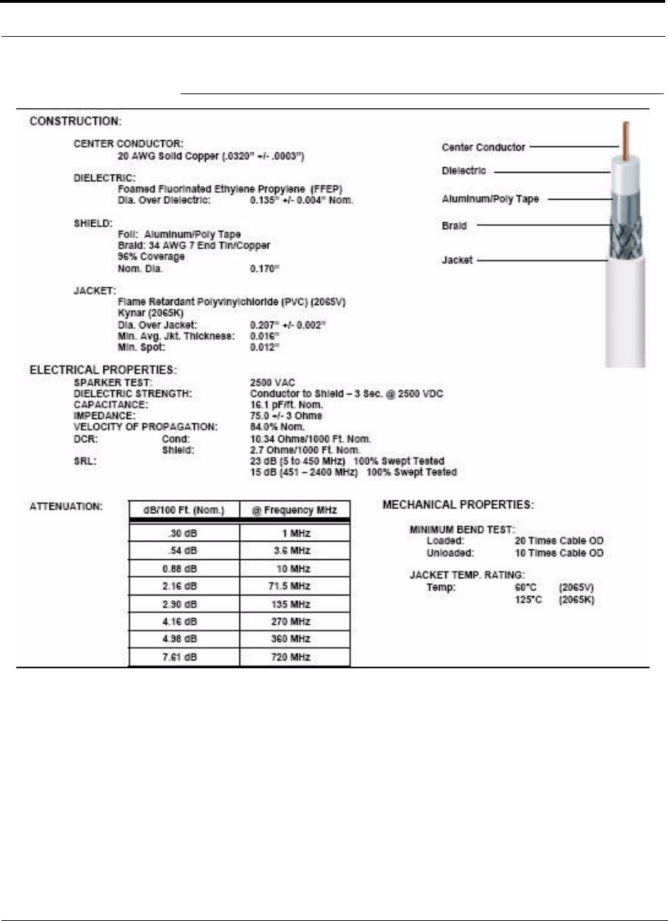
A-2 InterReach Fusion Installation, Operation, and Reference Manual
CONFIDENTIAL
D-620610-0-20 Rev A
Figure A-1
CommScope 2065V for RG-59
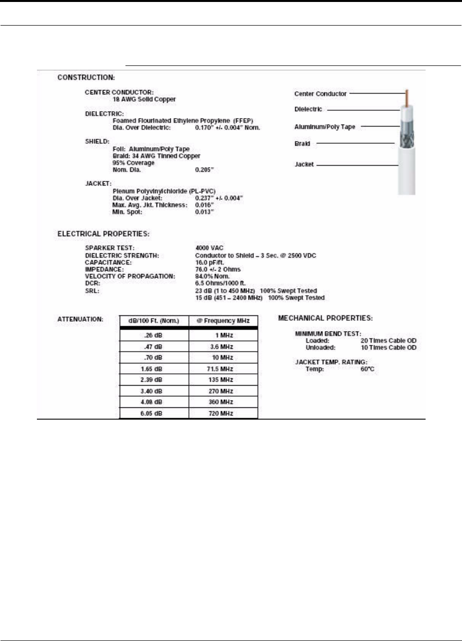
Help Hot Line (U.S. only): 1-800-530-9960 A-3
D-620610-0-20 Rev A
CONFIDENTIAL
Figure A-2
CommScope 2279V for RG-6
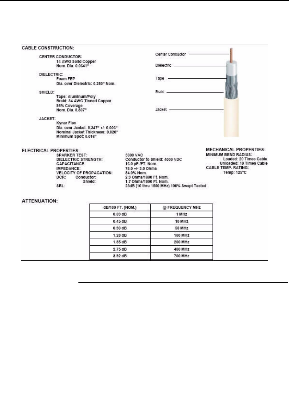
A-4 InterReach Fusion Installation, Operation, and Reference Manual
CONFIDENTIAL
D-620610-0-20 Rev A
Figure A-3
CommScope 2293K for RG-11
NOTE: LGC Wireless requires solid copper center conductor CATV cable for
proper DC voltage to the RAU and maximum distances.

Help Hot Line (U.S. only): 1-800-530-9960 A-5
D-620610-0-20 Rev A
CONFIDENTIAL
Use the following connectors and tools to prepare the cable ends:
CommScope cable part number: 2065V
Canare part number: F connector FP-C4F
Crimp Tool TC-1, Crimp Die TCD-4C, Cable Strip preparation tool TS100E
CommScope cable part number: 2279V
Canare part number: F connector FP-C55A
Crimp Tool TC-1, Crimp Die TCD-35CA, Cable Strip preparation tool TS100E
CommScope cable part number: 2293V
Canare part number: F connector FP-C71A
Crimp Tool TC-1, Crimp Die TCD-7CA, Cable Strip preparation tool TS100E
If the maximum distance is not required, then copper-clad over steel-center conductor
cable may be used to reduce cable costs.
Table A-2 shows CommScope cable choices of plenum, non-plenum, solid copper
conductor, and copper-clad over-steel conductor cable with their part numbers and
maximum distances.

A-6 InterReach Fusion Installation, Operation, and Reference Manual
CONFIDENTIAL
D-620610-0-20 Rev A
* Exceeding the distance of copper-clad cable will result in the attached RAU becoming
non-functional. If the distance of a cable run is at its maximum and is of concern, LGC recom-
mends the use of solid copper cable to ensure successful operation.
Table A-1
System Gain (Loss) Relative to CATV Cable Length (All RAUs except
800/900/1900)
Cable
Type
Comm-
Scope
Part
Number
Plenum
Rated
Solid
Copper
Conductor
Copper
Clad
Conductor
Zero-loss
RF
Maximum
Length
(meters)
Distance
Where
RF is
10dB
Below
Input RF
(meters)
RG-59
2065V Yes X 150 210
2022V Yes X 120 120*
5572R No X 110 110*
5565 No X 150 210
RG-6
2279V Yes X 170 230
2275V Yes X 170 175*
5726 No X 170 170*
5765 No X 170 230
RG-11
2293K Yes X 275 375
2285K Yes X 275 370*
5913 No X 275 370*

Help Hot Line (U.S. only): 1-800-530-9960 A-7
D-620610-0-20 Rev A
CONFIDENTIAL
* Exceeding the distance of copper-clad cable will result in the attached RAU becoming non-functional. If
the distance of a cable run is at its maximum and is of concern, LGC recommends the use of solid copper
cable to ensure successful operation.
Table A-2
System Gain (Loss) Relative to CATV Cable Length for 800/900/1900
RAUs
Cable
Type
Comm-
Scope
Part
Number
Plenum
Rated
Solid
Copper
Conductor
Copper
Clad
Conductor
Zero-loss
RF
Maximum
Length
(meters)
Distance
Where
RF is
10dB
Below
Input RF
(meters)
RG-59
2065V Yes X 150 210
2022V Yes X 80 80*
5572R No X 70 70*
5565 No X 150 210
RG-6
2279V Yes X 170 230
2275V Yes X 115 115*
5726 No X 110 110*
5765 No X 170 230
RG-11
2293K Yes X 275 375
2285K Yes X 240 240*
5913 No X 240 240*

A-8 InterReach Fusion Installation, Operation, and Reference Manual
CONFIDENTIAL
D-620610-0-20 Rev A
A.2Fiber Optical Cables
• Connects the Main Hub to Expansion Hub(s)
• Transmits (downlink) and receives (uplink) optical signals
• Carries configuration and status information
• Use industry-standard 62.5µm/125µm MMF or Corning SMF-28 fiber, or equiva-
lent.
• SC/APC (angle-polished) connectors are required throughout the fiber network
(port-to-port), including fiber distribution panels
• Distances:
• Multi-mode Fiber: up to 500 m (1,640 ft) – 3 dB optical loss maximum
• Single-mode Fiber: up to
6 km (19,685 ft)
– 3 dB optical loss maximum
A.3 Coaxial Cable
• Connects a Fusion Hub to a repeater or base station (N-type connectors)
• Connects an RAU to a passive antenna (N-type connectors)
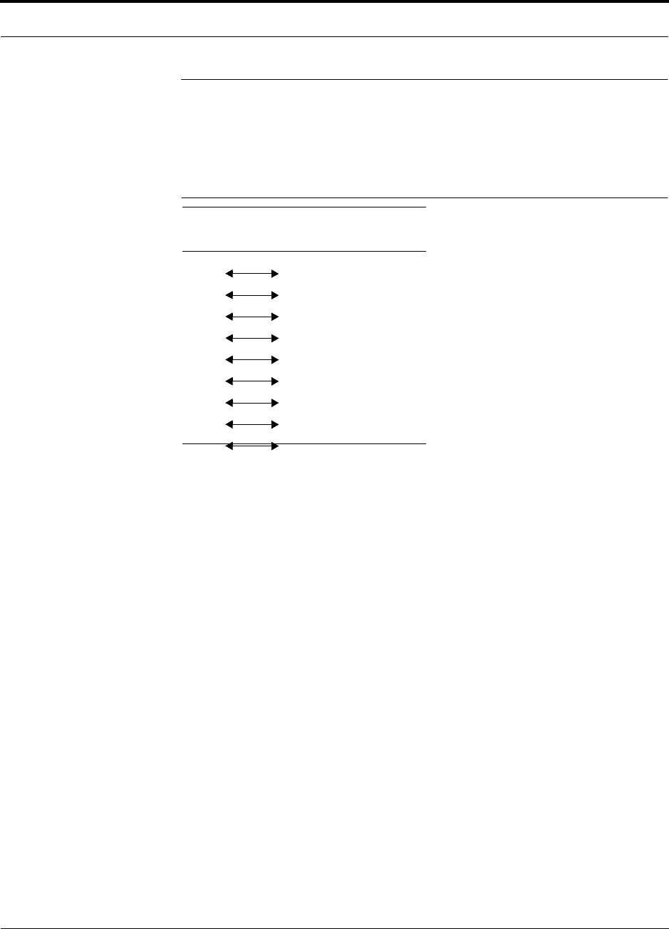
Help Hot Line (U.S. only): 1-800-530-9960 A-9
D-620610-0-20 Rev A
CONFIDENTIAL
A.4 Standard Modem Cable
This cable (PN 4028-10) connects a modem to the Fusion Hub’s front panel serial
port.
Figure A-1
Standard Modem Cable Pinout
DB-9 Connector
Pin
DB-25 Connector
Pin
1
2
3
4
5
6
7
8
9
8
3
2
20
7
6
4
5
22
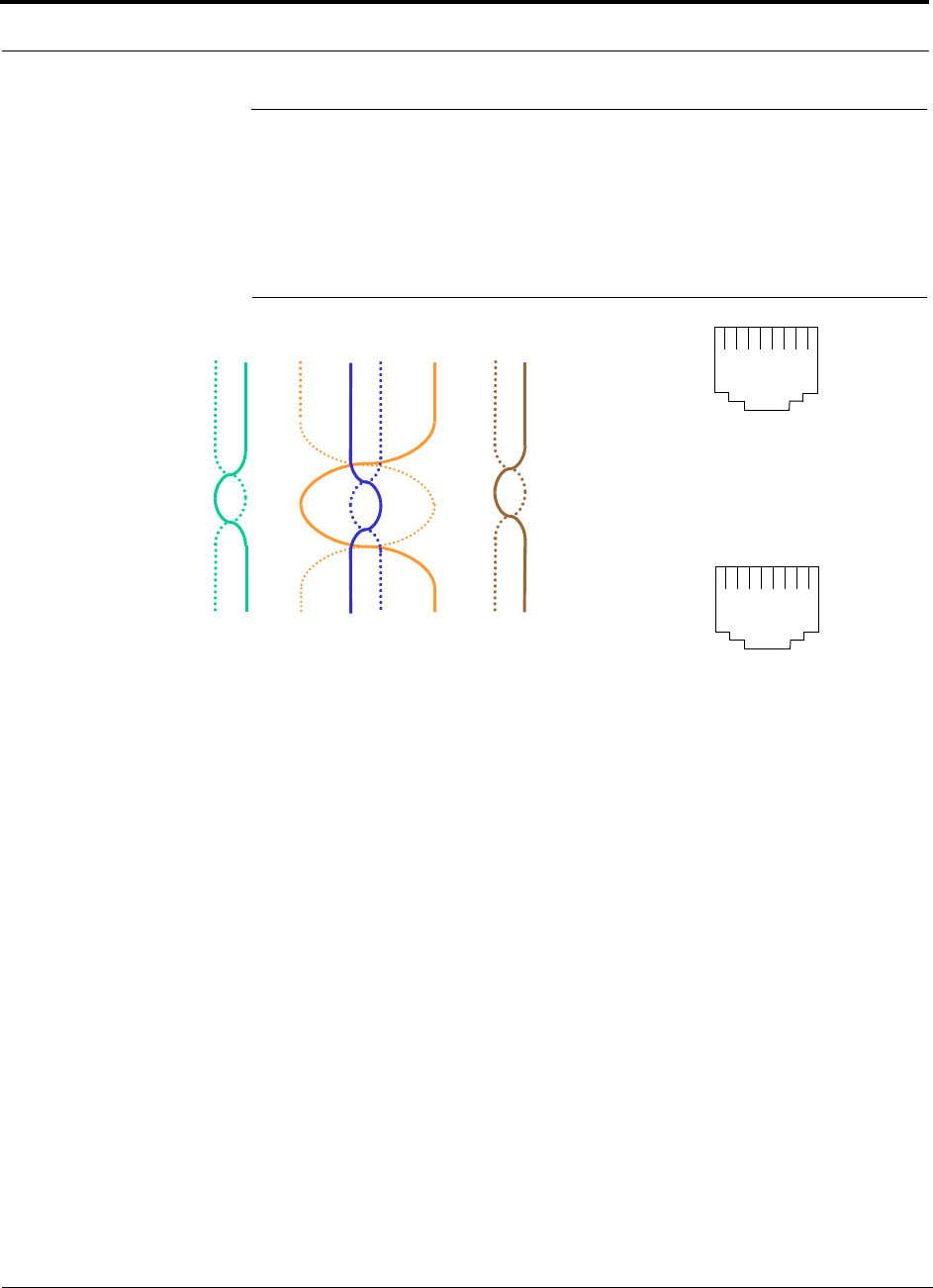
A-10 InterReach Fusion Installation, Operation, and Reference Manual
CONFIDENTIAL
D-620610-0-20 Rev A
A.5 TCP/IP Cross-over Cable
A TCP/IP cross-over cable (PN 4069-ADB) is used to connect a standard browser PC
to the AdminBrowser with a Fusion Hub. A cable is included with the Fusion Hub.
The pinouts for this cable are illustrated in Figure A-2.
Figure A-2
Wiring Map for TCP/IP Cable
1 2 3 4 5 6 7 8
Brown
Brown/
White
Blue Blue/
White
Green/
White
Green Orange
Orange/
White
Top View of the Wiring Map for Category 5 (CAT 5) UTP Cable
(TIA/EIA 568-A Standard)
Straight Connect
RJ-45 Port
12345678
W-G
G
W-O
BL
W-BL
O
W-BR
BR
RJ-45 Port
12345678
W-O
O
W-G
BL
W-BL
G
W-BR
BR
36 1 45 2 78
Connector 1
Connector 2
(586A)
(586B)
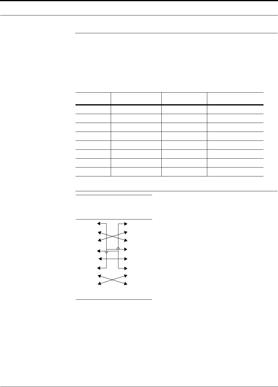
Help Hot Line (U.S. only): 1-800-530-9960 A-11
D-620610-0-20 Rev A
CONFIDENTIAL
A.6 DB-25 to DB-9 Null Modem Cable
Use a DB-9 female to DB-9 female null modem cable to connect the craft person’s
PC/Laptop to the RS-232 port on the front of the Fusion Hub for IP address configu-
ration. Table A-3 lists the cable pinout and Figure A-3 shows a diagram of its wiring.
Figure A-3
DB-9 Female to DB-9 Female Null Modem Cable Diagram
Table A-3
DB-9 Female to DB-9 Female Null Modem Cable Pinout
From Signal To Signal
P1-4 DTR P2-6, P2-1 DSR, DCD
P1-6 DSR P1-1, P2-4 DCD, DTR
P1-3 TXD P2-2 RXD
P1-2 RXD P2-3 TXD
P1-5 GND P2-5 GND
P1-7 RTS P2-8 CTS
P1-8 CTS P2-7 RTS
P1-9 N/C N/C N/C
Note that for each DB-9 connector, pins 1 and 6 are tied together and sent to pin 4
of the opposite connector, providing the required handshake signals.
DB-9
Connector
Pin
DB-9
Connector
Pin
1
2
3
4
5
6
7
8
9
1
2
3
4
5
6
7
8
9

A-12 InterReach Fusion Installation, Operation, and Reference Manual
CONFIDENTIAL
D-620610-0-20 Rev A

InterReach Fusion Installation, Operation, and Reference Manual B-1
D-620610-0-20 Rev A
CONFIDENTIAL
APPENDIX B
Compliance
B.1 Fusion System Approval Status
InterReach Fusion has been approved as shown below.
800 SMR/iDEN Products
• Safety: UL 60950, 3rd Edition
• EMC: FCC part 15 class A
• Radio: FCC Part90
850 Cellular Products
• Safety: CB scheme evaluation to IEC 60950, 3rd Edition with all national devia-
tions.
• EMC: FCC part 15 class A
• Radio: FCC Part 22
900 Paging/SMR/iDEN Products
• Safety: UL 60950, 3rd Edition
• EMC: FCC part 15 class A
• Radio: FCC Part 90
1800 DCS Products-Pending
• Safety: CB scheme evaluation to IEC 60950, 3rd Edition with all national devia-
tions.
• EMC: EN 301 489-8 V.1.2.1 (2002-08)
• Radio: EN 502 V.8.1.2 (2001-07)

B-2 InterReach Fusion Installation, Operation, and Reference Manual
CONFIDENTIAL
D-620610-0-20 Rev A
900 GSM/EGSM Products-Pending
• Safety: CB scheme evaluation to IEC 60950, 3rd Edition with all national devia-
tions.
• Radio: EN 301 502 V.8.1.2 (2001-07)
• EMC: EN 301 489-8 V.1.2.1 (2002-08)
1900 PCS Products
• Safety: CB scheme evaluation to IEC 60950, 3rd Edition with all national devia-
tions.
• EMC: FCC part 15 class A
• Radio: FCC part 24
2100 UMTS Products-Pending
• Safety: CB scheme evaluation to IEC 60950, 3rd Edition with all national devia-
tions.
• EMC: ETSI TS 125 113 125 113 (2005-12)
• Radio: EN 301 908-11 V2.3.1 (2004-10)
InterReach Fusion Main Hub and Expansion Hub
• Safety: CB scheme evaluation to IEC 60950-1, First Edition with all national devi-
ations.
• EMC: FCC part 15 class A
• Radio: EN 301 502 V.8.1.2 (2001-07)
• EMC: EN 301 489-8 V.1.2.
• EMC: ETSI TS 125 113 125 113 (2005-12)
• Radio: FCC Part 22H
• Radio: FCC part 24
• Radio: EN 301 908-11 V2.3.1 (2004-10)
• EMC: CISPR 22A
• EMC: CISPR 24
NOTE: for Canadian customers, the Manufacturer’s rated output power
1
of
this equipment is for single carrier operation. For situations when multiple
carrier signals are present, the rating would have to be reduced by 3.5 dB,
especially where the output signal is re-radiated and can cause interference

Help Hot Line (U.S. only): 1-800-530-9960 B-3
D-620610-0-20 Rev A
CONFIDENTIAL
to adjacent band users. This power reduction is to be by means of input
power or gain reduction and not by an attenuator at the output of the device.
NOTE: This device complies with Part 15 of the FCC Rules. Operation is
subject to the following two conditions: (1) this device may not cause harm-
ful interference, and (2) this device must accept any interference received,
including interference that may cause undesired operation.
B.2 Human Exposure to RF
The U.S. Federal Communications Commission (FCC) has developed guidelines for
evaluation of human exposure to RF emissions. The guidelines incorporate limits for
Maximum Permissible Exposure (MPE) for power density of transmitters operating
at frequencies between 300 kHz and 100 GHz. Limits have been set for portable,
mobile, and fixed equipment. LGC products fall in the category of fixed equipment;
products intended to be permanently secured and exposures are evaluated for dis-
tances greater than 20cm (7 7/8”). Portable devices fall into exposures of less than
20cm, are SAR evaluations are used.
Antenna gain is restricted to 1.5 W ERP (2.49 W EIRP) in order to satisfy RF expo-
sure compliance requirements. If higher than 1.5 W ERP, routine MPE evaluation is
needed. The antennas should be installed to provide at least 20 cm from all persons to
satisfy MPE requirements of FCC Part 2, 2.1091.
Basic MPE evaluation is performed by taking the maximum power output of the
equipment, the gain of the antenna to be used, and distance from the antenna, refer-
enced in FCC OET Bulletin 65 “Evaluation Compliance with FCC Guidelines for
Human Exposure to Radio Frequency for Electric Fields”.
LGC products transmit well below the FCC power density limits. FCC defines power
output limits
at 20cm distance for various frequency ranges:
• Over 300 mHz to 1.5 GHz the limit is determined by frequency/1500
• Above 1.5 GHz the limit is 1mW/cm2
The basic equation for determining power density is:
S = PG / 4πR
2
1. “Manufacturer’s rated output power” refers to Fusion’s downlink P1dB. The power per carrier tables take into account this
power reduction for multiple carriers.

B-4 InterReach Fusion Installation, Operation, and Reference Manual
CONFIDENTIAL
D-620610-0-20 Rev A
Where S is power density in mW/cm2
PG, the transmitted power from the antenna identified as EIRP (Equivalent Isotropi-
cally Radiated Power), is the product of power output of device and antenna gain, in
mW.
R is the distance of interest from the antenna.
Typical Installation Example:
Assuming an antenna is placed on a 10 foot ceiling, for a person 6 feet tall, the dis-
tance from antenna to body is 4 feet (112 cm.).
For a PCS 1900 or Cell 850 remote unit, the maximum power output, according to the
power table in Section 6.3 Maximum Output Power per Carrier on page 6-4, is 16.5
dB.
Assuming a 7 dBi antenna is used, PG in the equation is equal to 23.5 dB (224 mW)
EIRP.
Using S = PG/4
π
R
2
S = 224/(4x3.14) x (122)
2
= 0.001 mW/cm
2
Also, assuming a minimum distance of 20 cm according to FCC regulations”
S = 224/(4 x 3.14) x (20)
2
= 0.04 mW/cm
2

InterReach Fusion Installation, Operation, and Referencer Manual C-1
D-620610-0-20 Rev A
CONFIDENTIAL
APPENDIX C
Faults, Warnings, Status Tables
This appendix contains the following sections:
• Section C.1 Faults Reported by Fusion Main/SingleStar Hubs . . . . . . . . . . . A-1
• Section C.2 Faults Reported for System CPU . . . . . . . . . . . . . . . . . . . . . . . . A-5
• Section C.3 Faults for Fusion Expansion Hubs . . . . . . . . . . . . . . . . . . . . . . . A-6
• Section C.4 Faults for RAUs . . . . . . . . . . . . . . . . . . . . . . . . . . . . . . . . . . . . . A-9
• Section C.5 Warning/Status Messages for Fusion Main/SingleStar Hubs . . A-10
• Section C.6 Warning/Status Messages for System CPUs . . . . . . . . . . . . . . A-15
• Section C.7 Warning/Status Messages for Fusion Expansion Hubs . . . . . . A-16
• Section C.8 Warning /Status Messages for RAUs . . . . . . . . . . . . . . . . . . . . A-19
The following tables contain messages for all versions of firmware, but all messages
are not displayed by a given firmware version.
C.1 Faults Reported by Fusion Main/SingleStar Hubs
Faults indicate service-impacting conditions and should be given immediate atten-
tion.
Once all of the units are powered on and the cable connections are made, the faults
from each unit can be requested using AdminBrowser. Start with the Fusion Main
Hub and work downstream.
Resolve all faults first and then check the warnings. Take appropriate action to
resolve the faults, as indicated in the following tables. In cases where there is more
than one possible cause, they are listed from the “most likely” to the “least likely”
cause. Actions are listed in the order that they should be performed; not all actions
may need to be done.

C-2 InterReach Fusion Installation, Operation, and Referencer Manual
CONFIDENTIAL
D-620610-0-20 Rev A
NOTE: If you have a red
STATUS
LED without a fault message, it probably
indicates that the unit is locked out.
Table C-1
Fault Messages for Fusion Main/SingleStar Hubs
Message
Number Description Reason/Action
{MF01} Software error occurred and recovered. If this happens repeatedly, replace the Hub.
{MF02} Software error occurred and recovered. If this happens repeatedly, replace the Hub.
{MF03} Software error occurred and recovered. If this happens repeatedly, replace the Hub.
{MF04} Software reset occurred and recovered,
or firmware download.
If this happens repeatedly, replace the Hub.
{MF05} Software error occurred and recovered. If this happens repeatedly, replace the Hub.
{MF06} Problem detected in the Hub. Internal
communication reset.
Contact LGC Wireless Support for more information.
{MF07} Hub power cycle. Hub power cycle.
{MF08} Internal communications failure. No internal communications in preceding 15 minutes.
{MF09} Hardware Reset. Commanded hardware power on reset
{MF10} Band not programmed. Use AdminBrowser to program the band.
{MF11} Hardware failure (DL Pilot PLL). Cycle power once. If fault persists, replace the Hub
{MF12} Hardware failure (DL Pilot Too High). Cycle power once. If fault persists, replace the Hub.
{MF13} Hardware failure (DL Pilot Too Low). Cycle power once. If fault persists, replace the Hub.
{MF14} Hardware failure (54 VDC). 54 VDC power supply is out of range, replace the Hub
{MF15} Hardware failure (RF VDC Power). Loss of DC power to RF circuits, replace the Hub.
{MF16} Self Lockout (All Bands). Hub has shutdown the system due to an internal fault.
System is offline.
{MF17} Hardware failure (DL PLL Band 1). Cycle power once. If fault persists, replace the Hub.
{MF18} Hardware failure (UL PLL Band 1). Cycle power once. If fault persists, replace the Hub
{MF19} Commanded Out-of-service (Band 1). Band 1 commanded out-of-service by User.
{MF20} Problem detected in the Hub. Contact LGC Wireless Support for more information.
{MF21} Problem detected in the Hub. Contact LGC Wireless Support for more information.
{MF22} Problem detected in the Hub. Contact LGC Wireless Support for more information.
{MF23} Problem detected in the Hub Contact LGC Wireless Support for more information.
{MF24} Problem detected in the Hub. Contact LGC Wireless Support for more information.
{MF25} Hardware failure (DL PLL Band 2). Cycle power once. If fault persists, replace the Hub.
{MF26} Hardware failure (UL PLL Band 2). Cycle power once. If fault persists, replace the Hub.
{MF27} Commanded Out-of-service (Band 2). Band 2 commanded out-of-service by User.
{MF28} Problem detected in the Hub. Contact LGC Wireless Support for more information.
{MF29} Problem detected in the Hub. Contact LGC Wireless Support for more information.
{MF30} Problem detected in the Hub. Contact LGC Wireless Support for more information.
{MF31} Problem detected in the Hub. Contact LGC Wireless Support for more information.
{MF32} Problem detected in the Hub. Contact LGC Wireless Support for more information.
{MF33} Hardware failure (DL PLL Band 3). Cycle power once. If fault persists, replace the Hub.

Help Hot Line (U.S. only): 1-800-530-9960 C-3
D-620610-0-20 Rev A
CONFIDENTIAL
{MF34} Hardware failure (UL PLL Band 3). Cycle power once. If fault persists, replace the Hub.
{MF35} Commanded Out-of-service (Band 3). Band 3 commanded out-of-service by User.
{MF36} Problem detected in the Hub. Contact LGC Wireless Support for more information.
{MF37} Problem detected in the Hub Contact LGC Wireless Support for more information.
{MF38} Problem detected in the Hub. Contact LGC Wireless Support for more information.
{MF39} Problem detected in the Hub. Contact LGC Wireless Support for more information.
{MF40} Problem detected in the Hub. Contact LGC Wireless Support for more information.
{MF41} Hardware failure (Optical Power Out). Cycle power once. If the fault persists, replace the
Hub.
{MF42} Problem detected in the Hub Contact LGC Wireless Support for more information.
{MF43} Problem detected in the Hub. Contact LGC Wireless Support for more information.
{MF44} Problem detected in the Hub. Contact LGC Wireless Support for more information
{MF45} Problem detected in the Hub. Contact LGC Wireless Support for more information.
{MF46} Problem detected in the Hub. Contact LGC Wireless Support for more information.
{MF47} Problem detected in the Hub Contact LGC Wireless Support for more information.
{MF48} Problem detected in the Hub. Contact LGC Wireless Support for more information.
{MD129} Port 1 Disconnected. Unit is disconnected.
{MD130} Port 2 Disconnected. Unit is disconnected.
{MD131} Port 3 Disconnected. Unit is disconnected.
{MD132} Port 4 Disconnected. Unit is disconnected.
{MD133} Port 5 Disconnected. Unit is disconnected.
{MD134} Port 6 Disconnected. Unit is disconnected.
{MD135} Port 7 Disconnected. Unit is disconnected.
{MD136} Port 8 Disconnected. Unit is disconnected.
{MC137} Port 1 No Communications. No communications with remote unit.
{MC138} Port 2 No Communications. No communications with remote unit.
{MC139} Port 3 No Communications. No communications with remote unit.
{MC140} Port 4 No Communications. No communications with remote unit.
{MC141} Port 5 No Communications. No communications with remote unit.
{MC142} Port 6 No Communications. No communications with remote unit.
{MC143} Port 7 No Communications. No communications with remote unit.
{MC144} Port 8 No Communications. No communications with remote unit.
{MT145} Port 1 Cable Fault. Possible electrical short in the coax cable, or RAU
problem.
{MT146} Port 2 Cable Fault. Possible electrical short in the coax cable, or RAU
problem.
{MT147} Port 3 Cable Fault. Possible electrical short in the coax cable, or RAU
problem.
{MT148} Port 4 Cable Fault. Possible electrical short in the coax cable, or RAU
problem.
{MT149} Port 5 Cable Fault. Possible electrical short in the coax cable, or RAU
problem.
Table C-1
Fault Messages for Fusion Main/SingleStar Hubs (continued)
Message
Number Description Reason/Action

C-4 InterReach Fusion Installation, Operation, and Referencer Manual
CONFIDENTIAL
D-620610-0-20 Rev A
{MT150} Port 6 Cable Fault. Possible electrical short in the coax cable, or RAU
problem.
{MT151} Port 7 Cable Fault. Possible electrical short in the coax cable, or RAU
problem.
{MT152} Port 8 Cable Fault. Possible electrical short in the coax cable, or RAU
problem.
{MT153} Port 1 Trip. Remote Unit is drawing too much current.
{MT154} Port 2 Trip. Remote Unit is drawing too much current.
{MT155} Port 3 Trip. Remote Unit is drawing too much current.
{MT156} Port 4 Trip. Remote Unit is drawing too much current.
{MT157} Port 5 Trip. Remote Unit is drawing too much current.
{MT158} Port 6 Trip. Remote Unit is drawing too much current.
{MT159} Port 7 Trip. Remote Unit is drawing too much current.
{MT160} Port 8 Trip. Remote Unit is drawing too much current.
{MF161} Problem detected in the Hub. Contact LGC Wireless Support for more information.
{MF162} Problem detected in the Hub. Contact LGC Wireless Support for more information.
{MF163} Problem detected in the Hub. Contact LGC Wireless Support for more information.
{MF164} Problem detected in the Hub. Contact LGC Wireless Support for more information.
{MF165} Problem detected in the Hub. Contact LGC Wireless Support for more information.
{MF166} Problem detected in the Hub. Contact LGC Wireless Support for more information.
{MF167} Problem detected in the Hub. Contact LGC Wireless Support for more information.
{MF168} Problem detected in the Hub. Contact LGC Wireless Support for more information.
{MF169} Problem detected in the Hub. Contact LGC Wireless Support for more information.
{MF170} Problem detected in the Hub. Contact LGC Wireless Support for more information.
{MF171} Problem detected in the Hub. Contact LGC Wireless Support for more information.
{MF172} Problem detected in the Hub. Contact LGC Wireless Support for more information.
{MF173} Problem detected in the Hub. Contact LGC Wireless Support for more information.
{MF174} Problem detected in the Hub. Contact LGC Wireless Support for more information.
{MF175} Problem detected in the Hub. Contact LGC Wireless Support for more information.
{MF176} Problem detected in the Hub. Contact LGC Wireless Support for more information.
Table C-1
Fault Messages for Fusion Main/SingleStar Hubs (continued)
Message
Number Description Reason/Action

Help Hot Line (U.S. only): 1-800-530-9960 C-5
D-620610-0-20 Rev A
CONFIDENTIAL
C.2 Faults Reported for System CPU
Table C-2
Faults for System CPU
Message
Number Description Reason/Action
{SF01} No internal communications. No internal communications in preceding 2 minutes.
Power cycle to clear.
{SF02} Problem detected in the system CPU. System CPU performed self reboot to clear.
{SF03} Problem detected in the system CPU. System CPU performed self reboot to clear.
{SF04} Problem detected in the system CPU. Contact LGC Wireless Support for more information.
{SF05} Problem detected in the system CPU. Contact LGC Wireless Support for more information.
{SF06} Problem detected in the system CPU. Contact LGC Wireless Support for more information.
{SF07} Problem detected in the system CPU. Contact LGC Wireless Support for more information.
{SF08} Problem detected in the system CPU. Contact LGC Wireless Support for more information.
{SF09} Problem detected in the system CPU. Contact LGC Wireless Support for more information.
{SF10} Problem detected in the system CPU. Contact LGC Wireless Support for more information.
{SF11} Problem detected in the system CPU. Contact LGC Wireless Support for more information.
{SF12} Problem detected in the system CPU. Contact LGC Wireless Support for more information.
{SF13} Problem detected in the system CPU. Contact LGC Wireless Support for more information.
{SF14} Problem detected in the system CPU. Contact LGC Wireless Support for more information.
{SF15} Problem detected in the system CPU. Contact LGC Wireless Support for more information.
{SF16} Problem detected in the system CPU. Contact LGC Wireless Support for more information.
{SF17} Problem detected in the system CPU. Contact LGC Wireless Support for more information.
{SF18} Problem detected in the system CPU. Contact LGC Wireless Support for more information.
{SF19} Problem detected in the system CPU. Contact LGC Wireless Support for more information.
{SF20} Problem detected in the system CPU. Contact LGC Wireless Support for more information.
{SF21} Problem detected in the system CPU. Contact LGC Wireless Support for more information.
{SF22} Problem detected in the system CPU. Contact LGC Wireless Support for more information.
{SF23} Problem detected in the system CPU. Contact LGC Wireless Support for more information.
{SF24} Problem detected in the system CPU. Contact LGC Wireless Support for more information.
{SF25} Problem detected in the system CPU. Contact LGC Wireless Support for more information.
{SF26} Problem detected in the system CPU. Contact LGC Wireless Support for more information.
{SF27} Problem detected in the system CPU. Contact LGC Wireless Support for more information.
{SF28} Problem detected in the system CPU. Contact LGC Wireless Support for more information.
{SF29} Problem detected in the system CPU. Contact LGC Wireless Support for more information.
{SF30} Problem detected in the system CPU. Contact LGC Wireless Support for more information.
{SF31} Problem detected in the system CPU. Contact LGC Wireless Support for more information.
{SF32} Problem detected in the system CPU. Contact LGC Wireless Support for more information.

C-6 InterReach Fusion Installation, Operation, and Referencer Manual
CONFIDENTIAL
D-620610-0-20 Rev A
C.3 Faults for Fusion Expansion Hubs
Table C-3
Fault Messages for Fusion Expansion Hubs
Message
Number Description Reason/Action
{EF01} Software error occurred
and recovered.
If this happens repeatedly, replace the Hub.
{EF02} Software reset occurred
and recovered, or firm-
ware download.
If this happens repeatedly, replace the Hub.
{EF03} Software reset occurred
and recovered.
If this happens repeatedly, replace the Hub.
{EF04} Software reset occurred
and recovered.
If this happens repeatedly, replace the Hub.
{EF05} Software error occurred
and recovered.
If this happens repeatedly, replace the Hub.
{EF06} Firmware download. Firmware download.
{EF07} Hub power cycle. Hub power cycle.
{EF08} MH communications fail-
ure.
No communications from MH in THE preceding 90 seconds.
{EF09} MH communications fail-
ure.
EH uplink messages not getting to the MH.
{EF10} Hardware failure (PLL). Cycle power once. If the fault persists, replace the Hub.
{EF11} Hardware failure (54
VDC).
54 VDC power supply is out of range, replace the Hub.
{EF12} Problem detected in the
EH.
Contact LGC Wireless Support for more information.
{EF13} Band not programmed. Cycle power once. If the fault persists, replace the Hub.
{EF14} Low optical input power. Check downlink fiber connections.
{EF15} Hardware failure (Optical
Output Power).
Cycle power once. If the fault persists, replace the Hub.
{EF16} Self Lockout (All Bands). The Hub has shutdown the system due to an internal fault. The sys-
tem is offline.
{EF17} Commanded Out-of-ser-
vice (Band 1).
Band 1 commanded out-of-service by the user.
{EF18} Fault lockout (Band 1). Band 1 out-of-service due to an MH fault.
{EF19} Problem detected in the
EH.
Contact LGC Wireless Support for more information.
{EF20} Problem detected in the
EH.
Contact LGC Wireless Support for more information.
{EF21} Problem detected in the
EH.
Contact LGC Wireless Support for more information.
{EF22} Problem detected in the
EH.
Contact LGC Wireless Support for more information.
{EF23} Problem detected in the
EH.
Contact LGC Wireless Support for more information.
{EF24} Problem detected in the
EH.
Contact LGC Wireless Support for more information.
{EF25} Commanded Out-of-ser-
vice (Band 2).
Band 2 commanded out-of-service by the user.

Help Hot Line (U.S. only): 1-800-530-9960 C-7
D-620610-0-20 Rev A
CONFIDENTIAL
{EF26} Fault lockout (Band 2). Band 2 out-of-service due to MH fault.
{EF27} Problem detected in the
EH.
Contact LGC Wireless Support for more information.
{EF28} Problem detected in the
EH.
Contact LGC Wireless Support for more information.
{EF29} Problem detected in the
EH.
Contact LGC Wireless Support for more information.
{EF30} Problem detected in the
EH.
Contact LGC Wireless Support for more information.
{EF31} Problem detected in the
EH.
Contact LGC Wireless Support for more information.
{EF32} Problem detected in the
EH.
Contact LGC Wireless Support for more information.
{EF33} Commanded Out-of-ser-
vice (Band 3).
Band 3 commanded out-of-service by the user.
{EF34} Fault lockout (Band 3). Band 3 out-of-service due to an MH fault.
{EF35} Problem detected in the
EH.
Contact LGC Wireless Support for more information.
{EF36} Problem detected in the
EH.
Contact LGC Wireless Support for more information.
{EF37} Problem detected in the
EH.
Contact LGC Wireless Support for more information.
{EF38} Problem detected in the
EH.
Contact LGC Wireless Support for more information.
{EF39} Problem detected in the
EH.
Contact LGC Wireless Support for more information.
{EF40} Problem detected in the
EH.
Contact LGC Wireless Support for more information.
{ED129} Port 1 Disconnected. Unit is disconnected.
{ED130} Port 2 Disconnected. Unit is disconnected.
{ED131} Port 3 Disconnected. Unit is disconnected.
{ED132} Port 4 Disconnected. Unit is disconnected.
{ED133} Port 5 Disconnected. Unit is disconnected.
{ED134} Port 6 Disconnected. Unit is disconnected.
{ED135} Port 7 Disconnected. Unit is disconnected.
{ED136} Port 8 Disconnected. Unit is disconnected.
{EC137} Port 1 No Communica-
tions.
No communications with remote unit.
{EC138} Port 2 No Communica-
tions.
No communications with remote unit.
{EC139} Port 3 No Communica-
tions.
No communications with remote unit.
{EC140} Port 4 No Communica-
tions.
No communications with remote unit.
{EC141} Port 5 No Communica-
tions.
No communications with remote unit.
{EC142} Port 6 No Communica-
tions.
No communications with remote unit.
Table C-3
Fault Messages for Fusion Expansion Hubs (continued)
Message
Number Description Reason/Action

C-8 InterReach Fusion Installation, Operation, and Referencer Manual
CONFIDENTIAL
D-620610-0-20 Rev A
{EC143} Port 7 No Communica-
tions.
No communications with remote unit.
{EC144} Port 8 No Communica-
tions.
No communications with remote unit.
{ET145} Port 1 Cable Fault. Possible electrical short in the coaxial cable, or an RAU problem.
{ET146} Port 2 Cable Fault. Possible electrical short in the coaxial cable, or an RAU problem.
{ET147} Port 3 Cable Fault. Possible electrical short in the coaxial cable, or an RAU problem.
{ET148} Port 4 Cable Fault. Possible electrical short in the coaxial cable, or an RAU problem.
{ET149} Port 5 Cable Fault. Possible electrical short in the coaxial cable, or an RAU problem.
{ET150} Port 6 Cable Fault. Possible electrical short in the coaxial cable, or an RAU problem.
{ET151} Port 7 Cable Fault. Possible electrical short in the coaxial cable, or an RAU problem.
{ET152} Port 8 Cable Fault. Possible electrical short in the coaxial cable, or an RAU problem.
{ET153} Port 1 Trip. The Remote Unit is drawing too much current.
{ET154} Port 2 Trip. The Remote Unit is drawing too much current.
{ET155} Port 3 Trip. The Remote Unit is drawing too much current.
{ET156} Port 4 Trip. The Remote Unit is drawing too much current.
{ET157} Port 5 Trip. The Remote Unit is drawing too much current.
{ET158} Port 6 Trip. The Remote Unit is drawing too much current.
{ET159} Port 7 Trip. The Remote Unit is drawing too much current.
{ET160} Port 8 Trip. The Remote Unit is drawing too much current.
Table C-3
Fault Messages for Fusion Expansion Hubs (continued)
Message
Number Description Reason/Action

Help Hot Line (U.S. only): 1-800-530-9960 C-9
D-620610-0-20 Rev A
CONFIDENTIAL
C.4 Faults for RAUs
Table C-4
Faults for RAUs
Message
Number Description Reason/Action
{RF01} Software error occurred and recovered. If this happens repeatedly, replace the RAU.
{RF02} Software error occurred and recovered. If this happens repeatedly, replace the RAU.
{RF03} Software error occurred and recovered. If this happens repeatedly, replace the RAU.
{RF04} Software reset occurred and recovered,
or firmware download.
If this happens repeatedly, replace the RAU.
{RF05} Software error occurred and recovered. If this happens repeatedly, replace the RAU.
{RF06} Problem detected in the RAU. Contact LGC Wireless Support for more information.
{RF07} RAU power cycle. RAU power cycle.
{RF08} Problem detected in the RAU. Contact LGC Wireless Support for more information.
{RF09} Invalid band. The RAU doesn't support programmed band. Check the
RAU type against the band programmed in the hub.
{RF10} Low input DC voltage. Check the coaxial cable for high RF loss. Try another
Hub port. If the fault persists, replace the RAU. If the
fault clears, mark the Hub port as unusable and replace
the Hub when possible.
{RF11} Hardware Failure (DL PLL Band 1). Cycle power once. If the fault persists, replace the RAU.
{RF12} Hardware Failure (DL PLL Band 2). Cycle power once. If the fault persists, replace the RAU.
{RF13} Hardware Failure (DL PLL Band 3). Cycle power once. If the fault persists, replace the RAU.
{RF14} Hardware Failure (UL PLL Band 1). Cycle power once. If the fault persists, replace the RAU.
{RF15} Hardware Failure (UL PLL Band 2). Cycle power once. If the fault persists, replace the RAU.
{RF16} Hardware Failure (UL PLL Band 3). Cycle power once. If the fault persists, replace the RAU.
{RF17} Hardware Failure (PA Band 1). Cycle power once. If the fault persists, replace the RAU.
{RF18} Hardware Failure (PA Band 2). Cycle power once. If the fault persists, replace the RAU.
{RF19} Hardware Failure (PA Band 3). Cycle power once. If the fault persists, replace the RAU.
{RF20} Hardware Failure (UL Pilot). Cycle power once. If the fault persists, replace the RAU.
{RL21} Commanded Out-of-service (Band 1). Band 1 commanded out-of-service by User. Command
In-Service on Band 1 to restore service.
{RL22} Commanded Out-of-service (Band 2). Band 2 commanded out-of-service by User. Command
In-Service on Band 2 to restore service.
{RL23} Commanded Out-of-service (Band 3). Band 3 commanded out-of-service by User. Command
In-Service on Band 3 to restore service.
{RF24} Problem detected in the RAU. Contact LGC Wireless Support for more information.
{RX25} Commanded shutdown (Band 1). Check the status of hub to which the RAU is connected.
{RX26} Commanded shutdown (Band 2). Check the status of hub to which the RAU is connected.
{RX27} Commanded shutdown (Band 3). Check the status of the hub to which the RAU is con-
nected.
{RF28} Internal shutdown (Band 1). RAU Fault condition in band 1 path (or common path).
{RF29} Internal shutdown (Band 2). RAU Fault condition in band 2 path (or common path).
{RF30} Internal shutdown (Band 3). RAU Fault condition in band 3 path (or common path).
{RF31} Problem detected in the system. Contact LGC Wireless Support for more information.
{RF32} Problem detected in the RAU. Contact LGC Wireless Support for more information.

C-10 InterReach Fusion Installation, Operation, and Referencer Manual
CONFIDENTIAL
D-620610-0-20 Rev A
C.5 Warning/Status Messages for Fusion
Main/SingleStar Hubs
Warning Messages
Warnings alert you to conditions that indicate possible service impact. Warnings are
displayed in the Messages pane in red lettering.
Before addressing warnings, ensure that all faults are resolved. Take appropriate
action to resolve the warnings, as indicated in the following tables.
NOTE: AdminBrowser v0000007 or higher displays events (faults, warn-
ings, or status messages) depending on your view preference. To change
your view preference, refer to Section 3.3.2, “View Preference,” on page
3-10.
Status Messages
Status messages alert you to conditions that are important, but generally do not
impact service. Status messages alert you to conditions that are important, but gener-
ally do not impact service. Status messages are displayed in the Messages pane in
blue lettering.
NOTE: AdminBrowser v0000007 or higher displays events (faults, warn-
ings, or status messages) depending on your view preference. To change
your view preference, refer to Section 3.3.2, “View Preference,” on page
3-10.
NOTE: The icons displayed in the system status tree assume that there are
no other faults, warnings, or status present.
In Table C-5, the message number is in the following form:
[Mnn]/X where nn equals the message number, and X equals the default of either Sta-
tus (S) or Warning (W).

Help Hot Line (U.S. only): 1-800-530-9960 C-11
D-620610-0-20 Rev A
CONFIDENTIAL
Table C-5
Warnings/Status Messages for Fusion Main/SingleStar Hubs
Message
Number/
Default Description Reason/Action
[M01]/S Fan 1 failure. Check the fan for rotation, air flow blockage, and dust.
Replace the Hub on high temperature warning.
[M02]/S Fan 2 failure. Check the fan for rotation, air flow blockage, and dust.
Replace the Hub on high temperature warning.
[M03]/S 54 VDC Pwr Supply Fan failure. Check the fan for rotation, air flow blockage, and dust.
Replace the Hub on high temperature warning.
[M04]/W 5 VDC Monitor. DC power out of range, replace the Hub.
[M05]/W 9 VDC Monitor. DC power out of range, replace the Hub.
[M06]/W 54 VDC Monitor. DC power out of range, replace the Hub.
[M07]/W 3 VDC Monitor. DC power out of range, replace the Hub.
[M08]/W 12 VDC Monitor. DC power out of range, replace the Hub.
[M09]/W Temperature High. Reduce ambient temperature, check for air flow blockage,
fan rotation.
[M10]/W -5 VDC Monitor. DC power is out of range, replace the Hub.
[M11]/W High laser current. Output laser failure possible, replace the Hub when possi-
ble.
[M12]/W DL path loss is too high Replace the Hub.
[M13]/S Low input optical (Port 1). Check the uplink fiber.
[M14]/S Low input optical (Port 2). Check the uplink fiber.
[M15]/S Low input optical (Port 3). Check the uplink fiber.
[M16]/S Low input optical (Port 4). Check the uplink fiber.
[M17]/S Hardware failure (Test Tone PLL
Band 1).
Unable to perform DL system test.
[M18]/S Hardware failure (Test Tone Too
High Band 1).
Unable to perform DL system test.
[M19]/S Hardware failure (Test Tone Too
Low Band 1).
Unable to perform DL system test.
[M20]/W Overdrive limiter active (Band 1). Reduce input signal power to avoid potential component
damage.
[M21]/W CEMark limiter at maximum
(Band 1).
Reduce input signal power to avoid drop in system gain.
[M22]/W No DL test tone (Band 1). Hub DL gain is low.
[M23]/S No UL test tone (Band 1). Hub UL path gain is low.
[M24]/S Problem detected in the system. Contact LGC Wireless Support for more information.
[M25]/S Hardware failure (Test Tone PLL
Band 2).
Unable to perform DL system test. Replace the hub when
possible.
[M26]/S Hardware failure (Test Tone Too
High Band 2).
Unable to perform DL system test. Replace the hub when
possible.
[M27]/S Hardware failure (Test Tone Too
Low Band 2).
Unable to perform DL system test. Replace the hub when
possible.
[M28]/W Overdrive limiter active (Band 2). Reduce input signal power to avoid potential component
damage.
[M29]/W CEMark limiter at maximum
(Band 2).
Reduce input signal power to avoid drop in system gain.

C-12 InterReach Fusion Installation, Operation, and Referencer Manual
CONFIDENTIAL
D-620610-0-20 Rev A
[M30]/W No DL test tone (Band 2). Hub DL path gain is low.
[M31]/S No UL test tone (Band 2). Hub UL path gain is low.
[M32]/S Problem detected in the system. Contact LGC Wireless Support for more information.
[M33]/S Hardware failure (Test Tone PLL
Band 3).
Unable to perform DL system test.
[M34]/S Hardware failure (Test Tone Too
High Band 3).
Unable to perform DL system test.
[M35]/S Hardware failure (Test Tone Too
Low Band 3).
Unable to perform DL system test.
[M36]/W Overdrive limiter active (Band 3). Reduce input signal power to avoid potential component
damage.
[M37]/W CEMark limiter at maximum
(Band 3).
Reduce input signal power to avoid drop in system gain.
[M38]/W No DL test tone (Band 3). Hub DL path gain is low.
[M39]/S No UL test tone (Band 3). Hub UL path gain is low.
[M40]/S Problem detected in the Hub. Contact LGC Wireless Support for more information.
[M41]/W Port 1 No DL test tone (Band 1). Hub/Port DL path gain is low.
[M42]/W Port 2 No DL test tone (Band 1). Hub/Port DL path gain is low.
[M43]/W Port 3 No DL test tone (Band 1). Hub/Port DL path gain is low.
[M44]/W Port 4 No DL test tone (Band 1). Hub/Port DL path gain is low.
[M45]/W Port 5 No DL test tone (Band 1). Hub/Port DL path gain is low.
[M46]/W Port 6 No DL test tone (Band 1). Hub/Port DL path gain is low.
[M47]/W Port 7 No DL test tone (Band 1). Hub/Port DL path gain is low.
[M48]/W Port 8 No DL test tone (Band 1). Hub/Port DL path gain is low.
[M49]/W Port 1 No DL test tone (Band 2). Hub/Port DL path gain is low.
[M50]/W Port 2 No DL test tone (Band 2). Hub/Port DL path gain is low.
[M51]/W Port 3 No DL test tone (Band 2). Hub/Port DL path gain is low.
[M52]/W Port 4 No DL test tone (Band 2). Hub/Port DL path gain is low.
[M53]/W Port 5 No DL test tone (Band 2). Hub/Port DL path gain is low.
[M54]/W Port 6 No DL test tone (Band 2). Hub/Port DL path gain is low.
[M55]/W Port 7 No DL test tone (Band 2). Hub/Port DL path gain is low.
[M56]/W Port 8 No DL test tone (Band 2). Hub/Port DL path gain is low.
[M57]/W Port 1 No DL test tone (Band 3). Hub/Port DL path gain is low.
[M58]/W Port 2 No DL test tone (Band 3). Hub/Port DL path gain is low.
[M59]/W Port 3 No DL test tone (Band 3). Hub/Port DL path gain is low.
[M60]/W Port 4 No DL test tone (Band 3). Hub/Port DL path gain is low.
[M61]/W Port 5 No DL test tone (Band 3). Hub/Port DL path gain is low.
[M62]/W Port 6 No DL test tone (Band 3). Hub/Port DL path gain is low.
[M63]/W Port 7 No DL test tone (Band 3). Hub/Port DL path gain is low.
[M64]/W Port 8 No DL test tone (Band 3). Hub/Port DL path gain is low.
[M65]/S No UL test tone (Band 1). Hub/Port UL path gain is low.
Table C-5
Warnings/Status Messages for Fusion Main/SingleStar Hubs
Message
Number/
Default Description Reason/Action

Help Hot Line (U.S. only): 1-800-530-9960 C-13
D-620610-0-20 Rev A
CONFIDENTIAL
[M66]/S Problem detected in the Hub. Contact LGC Wireless Support for more information.
[M67]/S Problem detected in the Hub. Contact LGC Wireless Support for more information.
[M68]/S No UL test tone (Port 4/Band 1). Hub/Port UL path gain is low.
[M69]/S No UL test tone (Band 2). Hub/Port UL path gain is low.
[M70]/S No UL test tone (Port 2/Band 2). Hub/Port UL path gain is low.
[M71]/S No UL test tone (Port 3/Band 2). Hub/Port UL path gain is low.
[M72]/S No UL test tone (Port 4/Band 2). Hub/Port UL path gain is low.
[M73]/S No UL test tone (Band 3). Hub/Port UL path gain is low.
[M74]/S No UL test tone (Port 2/Band 3). Hub/Port UL path gain is low.
[M75]/S No UL test tone (Port 3/Band 3). Hub/Port UL path gain is low.
[M76]/S No UL test tone (Port 4/Band 3). Hub/Port UL path gain is low.
[M77]/S Problem detected in the Hub. Contact LGC Wireless Support for more information.
[M78]/S Problem detected in the Hub. Contact LGC Wireless Support for more information.
[M79]/S Problem detected in the Hub. Contact LGC Wireless Support for more information.
[M80]/S Problem detected in the Hub. Contact LGC Wireless Support for more information.
[M81]/W Port 1 DL path loss is high. If the problem is on more than one port, replace the Hub.
Switch the cable connection to a different hub port until the
Hub can be replaced.
[M82]/W Port 2 DL path loss is high. If the problem is on more than one port, replace the Hub.
Switch the cable connection to a different hub port until the
Hub can be replaced.
[M83]/W Port 3 DL path loss is high. If the problem is on more than one port, replace the Hub.
Switch the cable connection to a different hub port until the
Hub can be replaced.
[M84]/W Port 4 DL path loss is high. If the problem is on more than one port, replace the Hub.
Switch the cable connection to a different hub port until the
Hub can be replaced.
[M85]/W Port 5 DL path loss is high. If the problem is on more than one port, replace the Hub.
Switch the cable connection to a different hub port until the
Hub can be replaced.
[M86]/W Port 6 DL path loss is high. If the problem is on more than one port, replace the Hub.
Switch the cable connection to a different hub port until the
Hub can be replaced.
[M87]/W Port 7 DL path loss is high. If the problem is on more than one port, replace the Hub.
Switch the cable connection to a different hub port until the
Hub can be replaced.
[M88]/W Port 8 DL path loss is high. If the problem is on more than one port, replace the Hub.
Switch the cable connection to a different hub port until the
Hub can be replaced.
[M89]/W Port 1 UL path loss is high. Check the cable for high RF loss. Switch the cable connec-
tion to a different hub port. If the problem on more than one
port, replace the Hub, otherwise replace the RAU.
[M90]/W Port 2 UL path loss is high. Check the cable for high RF loss. Switch the cable connec-
tion to a different hub port. If the problem is on more than
one port, replace the Hub, otherwise replace the RAU.
[M91]/W Port 3 UL path loss is high. Check the cable for high RF loss. Switch the cable connec-
tion to a different hub port. If the problem is on more than
one port, replace the Hub, otherwise replace the RAU.
Table C-5
Warnings/Status Messages for Fusion Main/SingleStar Hubs
Message
Number/
Default Description Reason/Action

C-14 InterReach Fusion Installation, Operation, and Referencer Manual
CONFIDENTIAL
D-620610-0-20 Rev A
[M92]/W Port 4 UL path loss is high. Check the cable for high RF loss. Switch the cable connec-
tion to a different hub port. If the problem is on more than
one port, replace the Hub, otherwise replace the RAU.
[M93]/W Port 5 UL path loss is high. Check the cable for high RF loss. Switch the cable connec-
tion to a different hub port. If the problem is on more than
one port, replace the Hub, otherwise replace the RAU.
[M94]/W Port 6 UL path loss is high. Check the cable for high RF loss. Switch the cable connec-
tion to a different hub port. If the problem is on more than
one port, replace the Hub, otherwise replace the RAU.
[M95]/W Port 7 UL path loss is high. Check the cable for high RF loss. Switch the cable connec-
tion to a different hub port. If the problem is on more than
one port, replace the Hub, otherwise replace the RAU.
[M96]/W Port 8 UL path loss is high. Check the cable for high RF loss. Switch the cable connec-
tion to a different hub port. If the problem is on more than
one port, replace the Hub, otherwise replace the RAU.
[M97]/W Port 1 UL path exceeds maximum
gain.
If the problem is common to more than one port, replace
the Hub, otherwise check the RAU.
[M98]/W Port 2 UL path exceeds maximum
gain.
If the problem is common to more than one port, replace
the Hub, otherwise check the RAU.
[M99]/W Port 2 UL path exceeds maximum
gain.
If the problem is common to more than one port, replace
the Hub, otherwise check the RAU.
[M100]/W Port 2 UL path exceeds maximum
gain.
If the problem is common to more than one port, replace
the Hub, otherwise check the RAU.
[M101]/W Port 2 UL path exceeds maximum
gain.
If the problem is common to more than one port, replace
the Hub, otherwise check the RAU.
[M102]/W Port 2 UL path exceeds maximum
gain.
If the problem is common to more than one port, replace
the Hub, otherwise check the RAU.
[M103]/W Port 2 UL path exceeds maximum
gain.
If the problem is common to more than one port, replace
the Hub, otherwise check the RAU.
[M104]/W Port 8 UL path exceeds maximum
gain.
If the problem is common to more than one port, replace
the Hub, otherwise check the RAU.
[M105]/W Port 1 54 VDC Power Enabled. Caution: Port 54 VDC power may be present at the output.
[M106]/W Port 2 54 VDC Power Enabled. Caution: Port 54 VDC power may be present at the output.
[M107]/W Port 3 54 VDC Power Enabled. Caution: Port 54 VDC power may be present at the output.
[M108]/W Port 4 54 VDC Power Enabled. Caution: Port 54 VDC power may be present at the output.
[M109]/W Port 5 54 VDC Power Enabled. Caution: Port 54 VDC power may be present at the output.
[M110]/W Port 6 54 VDC Power Enabled. Caution: Port 54 VDC power may be present at the output.
[M111]/W Port 7 54 VDC Power Enabled. Caution: Port 54 VDC power may be present at the output.
[M112]/W Port 8 54 VDC Power Enabled. Caution: Port 54 VDC power may be present at the output.
Table C-5
Warnings/Status Messages for Fusion Main/SingleStar Hubs
Message
Number/
Default Description Reason/Action

Help Hot Line (U.S. only): 1-800-530-9960 C-15
D-620610-0-20 Rev A
CONFIDENTIAL
C.6 Warning/Status Messages for System CPUs
In Table C-6, the message number is in the following form:
[Snn]/X where nn equals the message number, and X equals the default of either Sta-
tus (S) or Warning (W).
Table C-6
Warning/Status Messages for System CPUs
Message
Number/
Default Description Reason/Action
[S01]/W Alarm Input 1. Check equipment connected to alarm input 1.
[S02]/W Alarm Input 2. Check equipment connected to alarm input 2.
[S03]/W Alarm Input 3. Check equipment connected to alarm input 3.
[S04]/S Problem detected in the system CPU. Retrieve the TTL and erase.
[S05]/S Problem detected in the system CPU. Contact LGC Wireless Support for more information.
[S06]/S Problem detected in the system CPU. Contact LGC Wireless Support for more information.
[S07]/S Problem detected in the system CPU. Contact LGC Wireless Support for more information.
[S08]/S Problem detected in the system CPU. Contact LGC Wireless Support for more information.
[S09]/S Time-tagged Log is full. Retrieve the TTL and erase.
[S10]/S Problem detected in the system CPU. Contact LGC Wireless Support for more information.
[S11]/S Problem detected in the system CPU. Contact LGC Wireless Support for more information.
[S12]/S Problem detected in the system CPU. Contact LGC Wireless Support for more information.
[S13]/S Problem detected in the system CPU. Contact LGC Wireless Support for more information.
[S14]/S Problem detected in the system CPU. Contact LGC Wireless Support for more information.
[S15]/S Problem detected in the system CPU. Contact LGC Wireless Support for more information.
[S16]/S Problem detected in the system CPU. Contact LGC Wireless Support for more information.

C-16 InterReach Fusion Installation, Operation, and Referencer Manual
CONFIDENTIAL
D-620610-0-20 Rev A
C.7 Warning/Status Messages for Fusion Expansion
Hubs
Table C-7
Warning/Status Message for Fusion Expansion Hubs
Message
Number
/Default Description Reason/Action
[E01]/W Alarm Input 1. Check the equipment connected to alarm input 1.
[E02]/W Alarm Input 2. Check the equipment connected to alarm input 2.
[E03]/W Alarm Input 3. Check the equipment connected to alarm input 3.
[E04]/S Problem detected in the EH. Contact LGC Wireless Support for more information.
[E05]/W SNMP Trap #1. TBD.
[E06]/W SNMP Trap #2. TBD.
[E07]/W SNMP Trap #3. TBD.
[E08]/S Problem detected in the EH. Contact LGC Wireless Support for more information.
[E09]/S Fan 1 failure. Check the fan for proper rotation, air flow blockage, and dust
accumulation. Replace the Hub on high temperature warning.
[E10]/S Fan 2 failure. Check the fan for proper rotation, air flow blockage, and dust
accumulation. Replace the Hub on high temperature warning.
[E11]/W -5 VDC Monitor. DC power out of range, replace the Hub.
[E12]/W 5 VDC Monitor. DC power out of range, replace the Hub.
[E13]/W 9 VDC Monitor. DC power out of range, replace the Hub.
[E14]/W 54 VDC Pwr Supply failure. DC port power supply out of range, replace the Hub.
[E15]/W 3 VDC Monitor. DC power out of range, replace the Hub.
[E16]/W 12 VDC Monitor. DC power out of range, replace the Hub.
[E17]/W Temperature High. Reduce the ambient temperature, check for air flow blockage,
fan rotation.
[E18]/W DL path exceeds maximum gain. If the problem is common to more than one port, replace the
MH, otherwise check the EH.
[E19]/W DL path loss is high. Check the cable for high RF loss. Switch the cable connec-
tion to a different MH port. If the problem is on more than
one port, replace the EH, otherwise replace the RAU.
[E20]/W Hardware Failure (High UL
Pilot).
Cycle power once. If the fault persists, replace the EH.
[E21]/W Hardware Failure (Low UL
Pilot).
Cycle power once. If the fault persists, replace the EH.
[E22]/W Low optical input power. Check the downlink fiber connection.
[E23]/W High laser current. Contact LGC Wireless Support for more information.
[E24]/S Problem detected in the EH. Contact LGC Wireless Support for more information.
[E25]/W Port 1 No DL test tone (Band 1). Hub/Port DL path gain is low.
[E26]/W Port 2 No DL test tone (Band 1). Hub/Port DL path gain is low.
[E27]/W Port 3 No DL test tone (Band 1). Hub/Port DL path gain is low.
[E28]/W Port 4 No DL test tone (Band 1). Hub/Port DL path gain is low.
[E29]/W Port 5 No DL test tone (Band 1). Hub/Port DL path gain is low.
[E30]/W Port 6 No DL test tone (Band 1). Hub/Port DL path gain is low.
[E31]/W Port 7 No DL test tone (Band 1). Hub/Port DL path gain is low.

Help Hot Line (U.S. only): 1-800-530-9960 C-17
D-620610-0-20 Rev A
CONFIDENTIAL
[E32]/W Port 8 No DL test tone (Band 1). Hub/Port DL path gain is low.
[E33]/W Port 1 No DL test tone (Band 2). Hub/Port DL path gain is low.
[E34]/W Port 2 No DL test tone (Band 2). Hub/Port DL path gain is low.
[E35]/W Port 3 No DL test tone (Band 2). Hub/Port DL path gain is low.
[E36]/W Port 4 No DL test tone (Band 2). Hub/Port DL path gain is low.
[E37]/W Port 5 No DL test tone (Band 2). Hub/Port DL path gain is low.
[E38]/W Port 6 No DL test tone (Band 2). Hub/Port DL path gain is low.
[E39]/W Port 7 No DL test tone (Band 2). Hub/Port DL path gain is low.
[E40]/W Port 8 No DL test tone (Band 2). Hub/Port DL path gain is low.
[E41]/W Port 1 No DL test tone (Band 3). Hub/Port DL path gain is low.
[E42]/W Port 2 No DL test tone (Band 3). Hub/Port DL path gain is low.
[E43]/W Port 3 No DL test tone (Band 3). Hub/Port DL path gain is low.
[E44]/W Port 4 No DL test tone (Band 3). Hub/Port DL path gain is low.
[E45]/W Port 5 No DL test tone (Band 3). Hub/Port DL path gain is low.
[E46]/W Port 6 No DL test tone (Band 3). Hub/Port DL path gain is low.
[E47]/W Port 7 No DL test tone (Band 3). Hub/Port DL path gain is low.
[E48]/W Port 8 No DL test tone (Band 3). Hub/Port DL path gain is low.
[E49]/W Port 1 DL path loss is high. If the problem is on more than one port, replace the Hub.
Switch the cable connection to a different hub port until the
Hub can be replaced.
[E50]/W Port 2 DL path loss is high. If the problem is on more than one port, replace the Hub.
Switch the cable connection to a different hub port until the
Hub can be replaced.
[E51]/W Port 3 DL path loss is high. If the problem is on more than one port, replace the Hub.
Switch the cable connection to a different hub port until the
Hub can be replaced.
[E52]/W Port 4 DL path loss is high. If the problem is on more than one port, replace the Hub.
Switch the cable connection to a different hub port until the
Hub can be replaced.
[E53]/W Port 5 DL path loss is high. If the problem is on more than one port, replace the Hub.
Switch the cable connection to a different hub port until the
Hub can be replaced.
[E54]/W Port 6 DL path loss is high. If the problem is on more than one port, replace the Hub.
Switch the cable connection to a different hub port until the
Hub can be replaced.
[E55]/W Port 7 DL path loss is high. If the problem is on more than one port, replace the Hub.
Switch the cable connection to a different hub port until the
Hub can be replaced.
[E56]/W Port 8 DL path loss is high. If the problem is on more than one port, replace the Hub.
Switch the cable connection to a different hub port until the
Hub can be replaced.
[E57]/W Port 1 UL path loss is high. Check the cable for high RF loss. Switch the cable connec-
tion to a different hub port. If the problem is on more than
one port, replace the Hub, otherwise replace the RAU.
[E58]/W Port 2 UL path loss is high. Check the cable for high RF loss. Switch the cable connec-
tion to a different hub port. If the problem is on more than
one port, replace the Hub, otherwise replace the RAU.
Table C-7
Warning/Status Message for Fusion Expansion Hubs (continued)
Message
Number
/Default Description Reason/Action

C-18 InterReach Fusion Installation, Operation, and Referencer Manual
CONFIDENTIAL
D-620610-0-20 Rev A
[E59]/W Port 3 UL path loss is high. Check the cable for high RF loss. Switch the cable connec-
tion to a different hub port. If the problem is on more than
one port, replace the Hub, otherwise replace the RAU.
[E60]/W Port 4 UL path loss is high. Check the cable for high RF loss. Switch the cable connec-
tion to a different hub port. If the problem is on more than
one port, replace the Hub, otherwise replace the RAU.
[E61]/W Port 5 UL path loss is high. Check the cable for high RF loss. Switch the cable connec-
tion to a different hub port. If the problem is on more than
one port, replace the Hub, otherwise replace the RAU.
[E62]/W Port 6 UL path loss is high. Check the cable for high RF loss. Switch the cable connec-
tion to a different hub port. If the problem is on more than
one port, replace the Hub, otherwise replace the RAU.
[E63]/W Port 7 UL path loss is high. Check the cable for high RF loss. Switch the cable connec-
tion to a different hub port. If the problem is on more than
one port, replace the Hub, otherwise replace the RAU.
[E64]/W Port 8 UL path loss is high. Check the cable for high RF loss. Switch the cable connec-
tion to a different hub port. If the problem is on more than
one port, replace the Hub, otherwise replace the RAU.
[E65]/W Port 1 UL path exceeds maxi-
mum gain.
If the problem is common to more than one port, replace the
Hub, otherwise check RAU.
[E66]/W Port 2 UL path exceeds maxi-
mum gain.
If the problem is common to more than one port, replace the
Hub, otherwise check RAU.
[E67]/W Port 3 UL path exceeds maxi-
mum gain.
If the problem is common to more than one port, replace the
Hub, otherwise check RAU.
[E68]/W Port 4 UL path exceeds maxi-
mum gain.
If the problem is common to more than one port, replace the
Hub, otherwise check RAU.
[E69]/W Port 5 UL path exceeds maxi-
mum gain.
If the problem is common to more than one port, replace the
Hub, otherwise check RAU.
[E70]/W Port 6 UL path exceeds maxi-
mum gain.
If the problem is common to more than one port, replace the
Hub, otherwise check RAU.
[E71]/W Port 7 UL path exceeds maxi-
mum gain.
If problem is common to more than one port, replace the Hub,
otherwise check RAU.
[E72]/W Port 8 UL path exceeds maxi-
mum gain.
If the problem is common to more than one port, replace the
Hub, otherwise check RAU.
[E73]/W Port 1 54 VDC Power Enabled. Caution: Port 54 VDC power may be present at the output.
[E74]/W Port 2 54 VDC Power Enabled. Caution: Port 54 VDC power may be present at the output.
[E75]/W Port 3 54 VDC Power Enabled. Caution: Port 54 VDC power may be present at the output.
[E76]/W Port 4 54 VDC Power Enabled. Caution: Port 54 VDC power may be present at the output.
[E77]/W Port 5 54 VDC Power Enabled. Caution: Port 54 VDC power may be present at the output.
[E78]/W Port 6 54 VDC Power Enabled. Caution: Port 54 VDC power may be present at the output.
[E79]/W Port 7 54 VDC Power Enabled. Caution: Port 54 VDC power may be present at the output.
[E80]/W Port 8 54 VDC Power Enabled. Caution: Port 54 VDC power may be present at the output.
Table C-7
Warning/Status Message for Fusion Expansion Hubs (continued)
Message
Number
/Default Description Reason/Action

Help Hot Line (U.S. only): 1-800-530-9960 C-19
D-620610-0-20 Rev A
CONFIDENTIAL
C.8 Warning /Status Messages for RAUs
In Table C-8, the message number is in the following form:
[Rnn]/X where nn equals the message number, and X equals the default of either Sta-
tus (S) or Warning (W).
Table C-8
Warning/Status Messages for RAUs
Message
Number
Default Description Reason/Action
[R01]/W Temperature High. Check RAU location for excessive temperature; check for
air flow blockage and/or incorrect installation. Move the
RAU to a cooler environment.
[R02]/W No communications from Hub. Check the cable for high RF loss. Switch the cable connec-
tion to a different hub port. If the problem persists, replace
the RAU.
[R03]/W DL RF path loss is too high. Check the cable for high RF loss. Switch the cable connec-
tion to a different hub port. If the problem persists, replace
the RAU.
[R04]/W DL RF path exceeds maximum
gain.
Check the Hub for proper operation; switch the cable con-
nection to a different hub port. If the problem persists,
replace the RAU.
[R05]/S DL RF path problem (Band 1). Unable to complete the DL system end-to-end test, replace
the RAU when possible.
[R06]/S DL RF path problem (Band 2). Unable to complete the DL system end-to-end test, replace
the RAU when possible.
[R07]/S DL RF path problem (Band 3). Unable to complete the DL system end-to-end test, replace
the RAU when possible.
[R08]/S System test required. Run system test.
[R09]/W Antenna Disconnected. Check RAU antenna connection; re-run system test.
[R10]/S UL RF path problem (Band 1). Unable to complete the UL system end-to-end test, replace
the RAU when possible.
[R11]/S UL RF path problem (Band 2). Unable to complete the UL system end-to-end test, replace
the RAU when possible.
[R12]/S UL RF path problem (Band 3). Unable to complete the UL system end-to-end test, replace
the RAU when possible.
[R13]/S Problem detected in the RAU. Contact LGC Wireless Support for more information.
[R14]/S Problem detected in the RAU. Contact LGC Wireless Support for more information.
[R15]/S Problem detected in the RAU. Contact LGC Wireless Support for more information.
[R16]/S Problem detected in the RAU. Contact LGC Wireless Support for more information.

C-20 InterReach Fusion Installation, Operation, and Referencer Manual
CONFIDENTIAL
D-620610-0-20 Rev A