ADC Telecommunications FSN-809019-2 InterReach Fusion FSN-809019-2 User Manual fusionBOOK
ADC Telecommunications Inc. InterReach Fusion FSN-809019-2 fusionBOOK
UserManual.wiki
>
ADC Telecommunications
>
FSN-809019-2 User Manual
>
User Manual Part Two
Contents
1.
User Manual Part One
2.
User Manual Part Two
User Manual Part Two
Navigation menu
Upload a User Manual
Namespaces
Wiki Guide
HTML
PDF
Info
Views
User Manual
Discussion / Help
Navigation
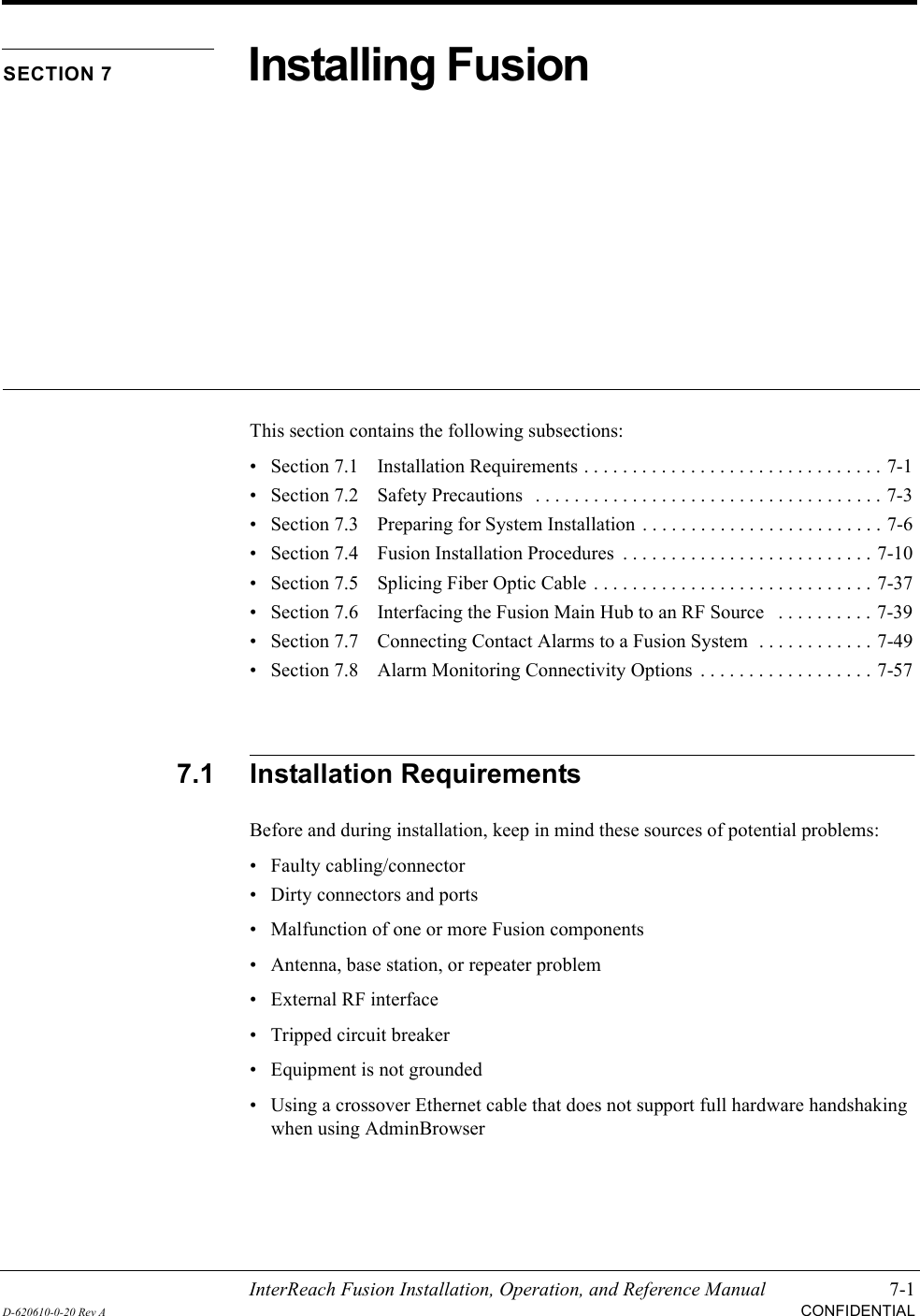
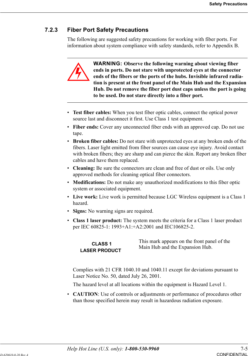
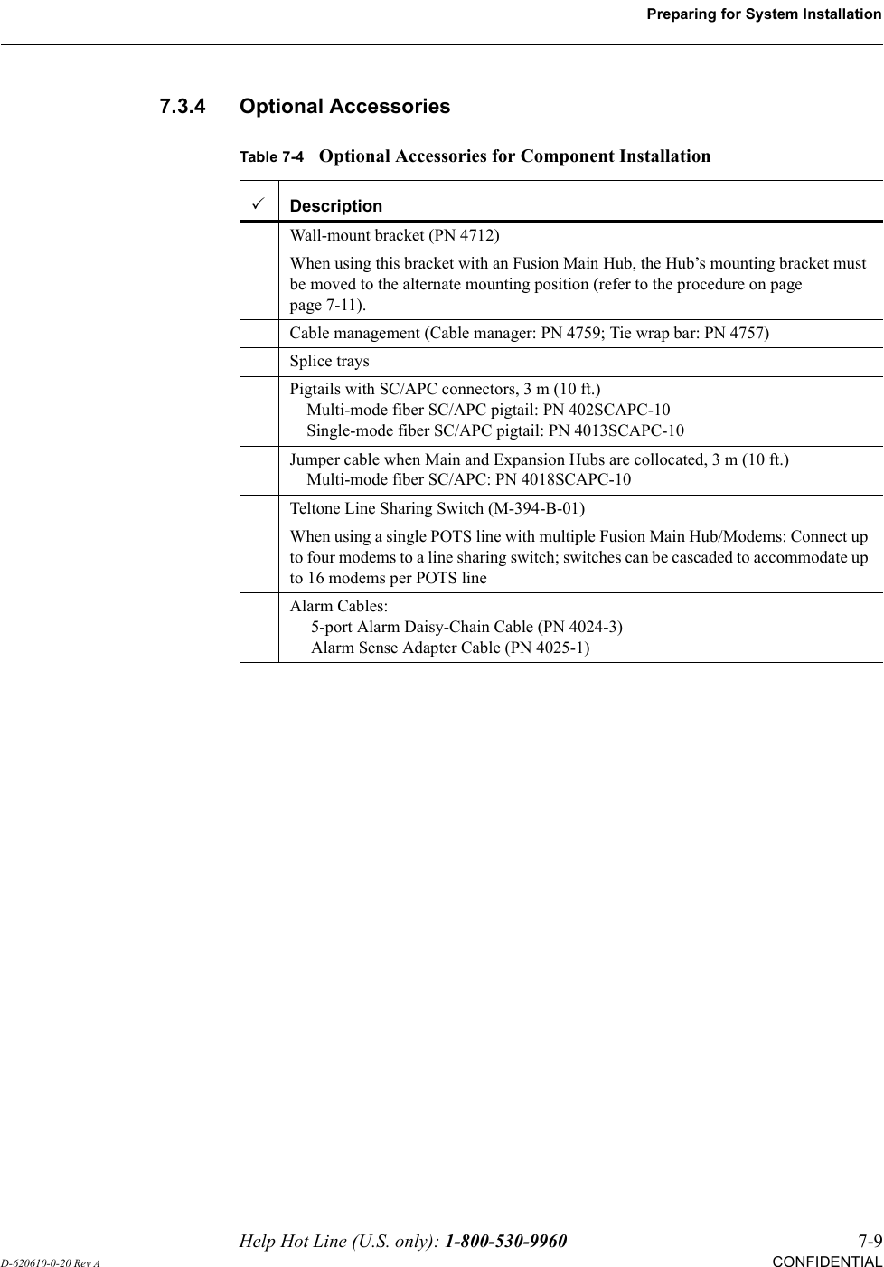
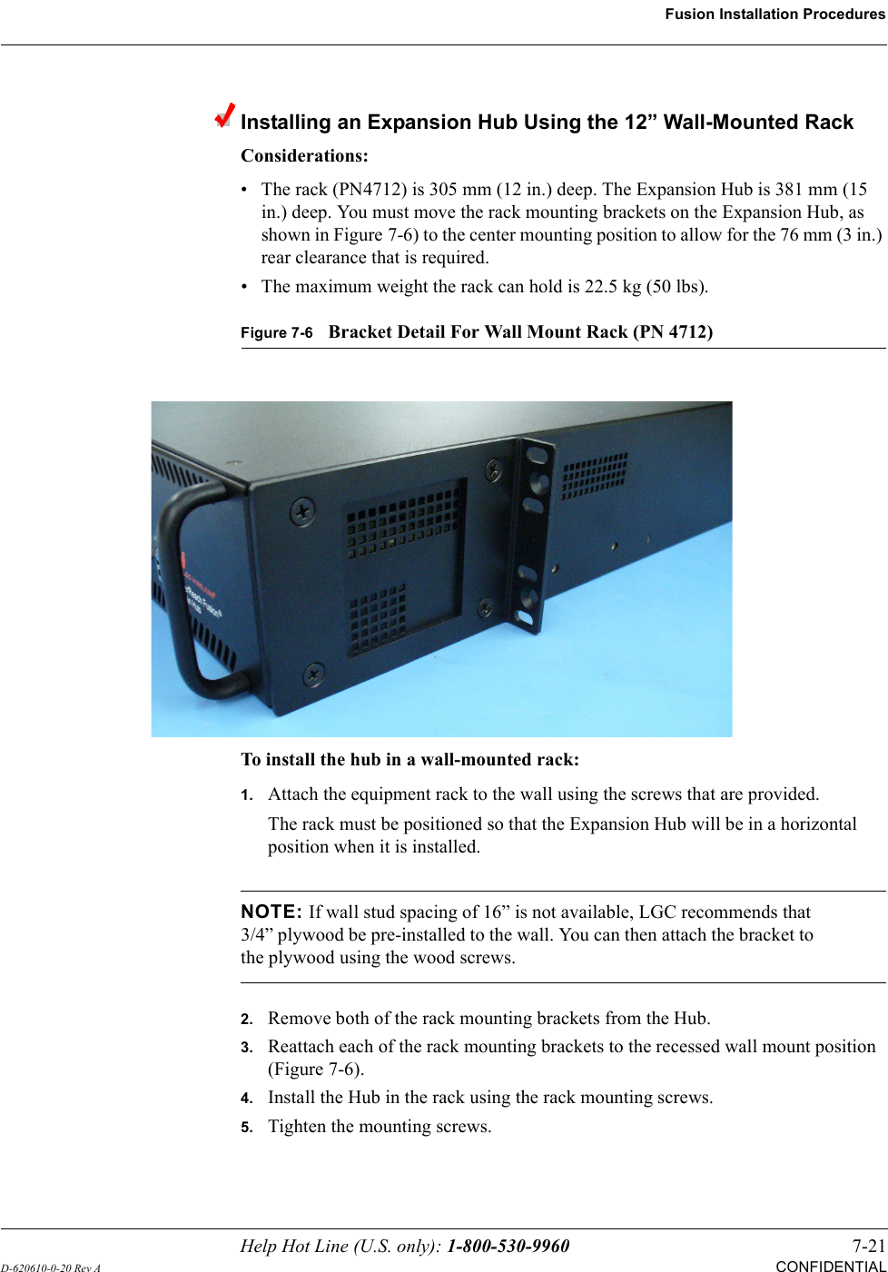
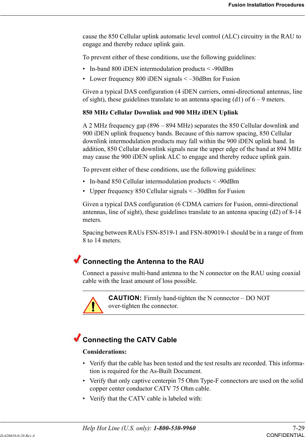
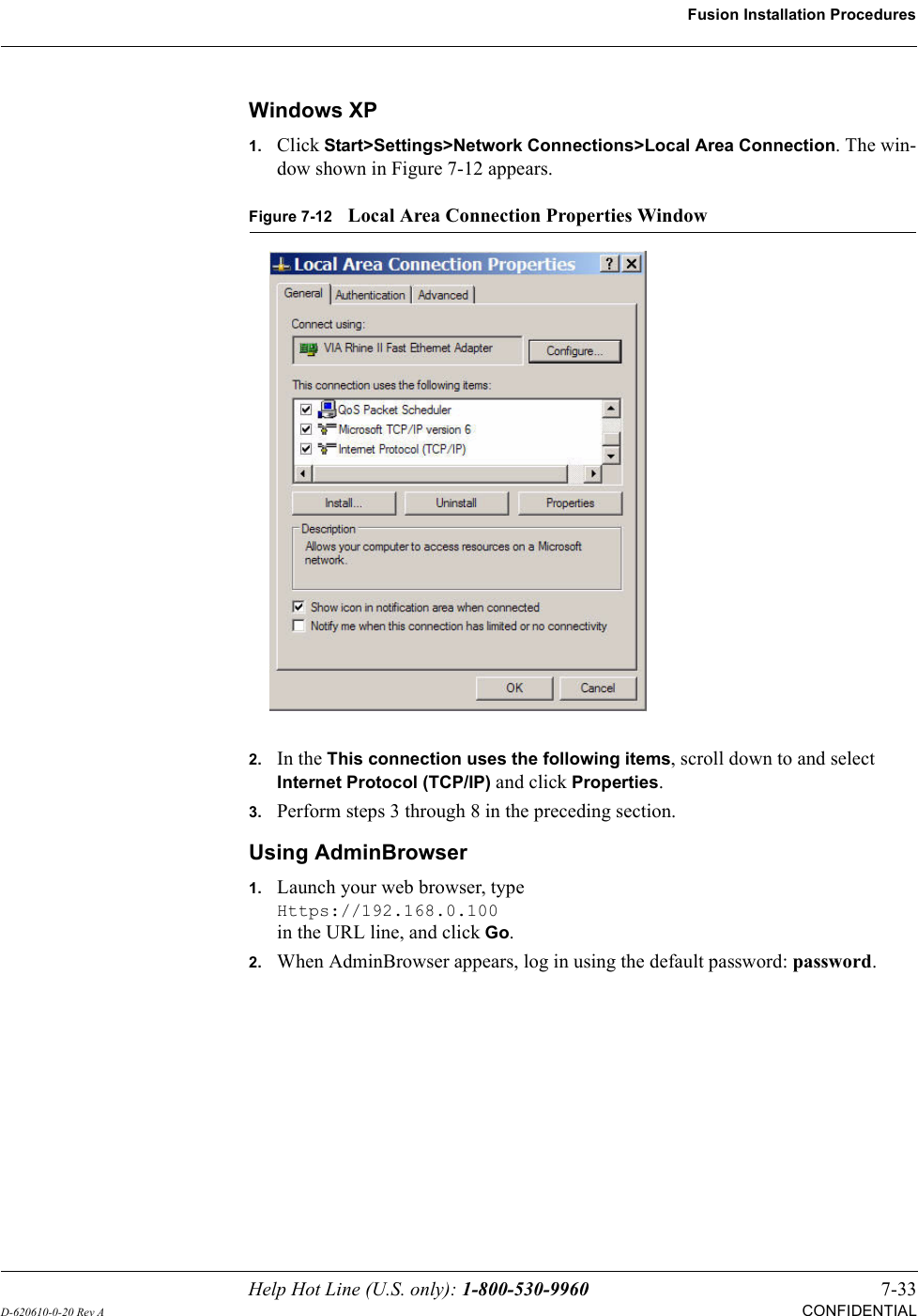
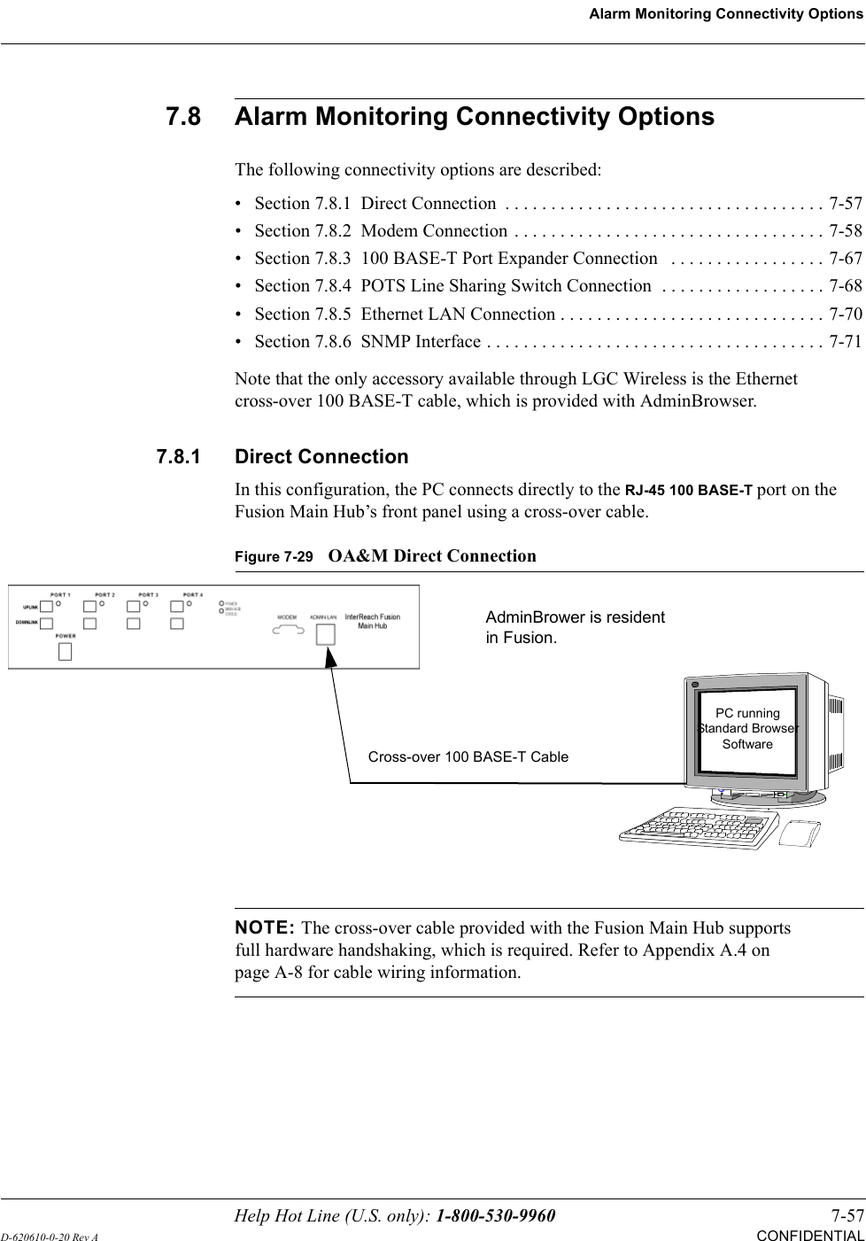
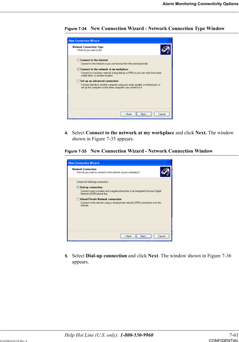
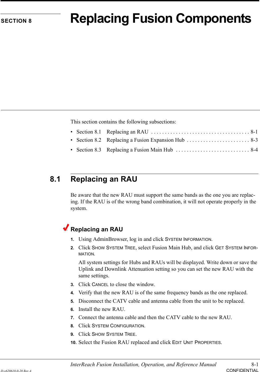
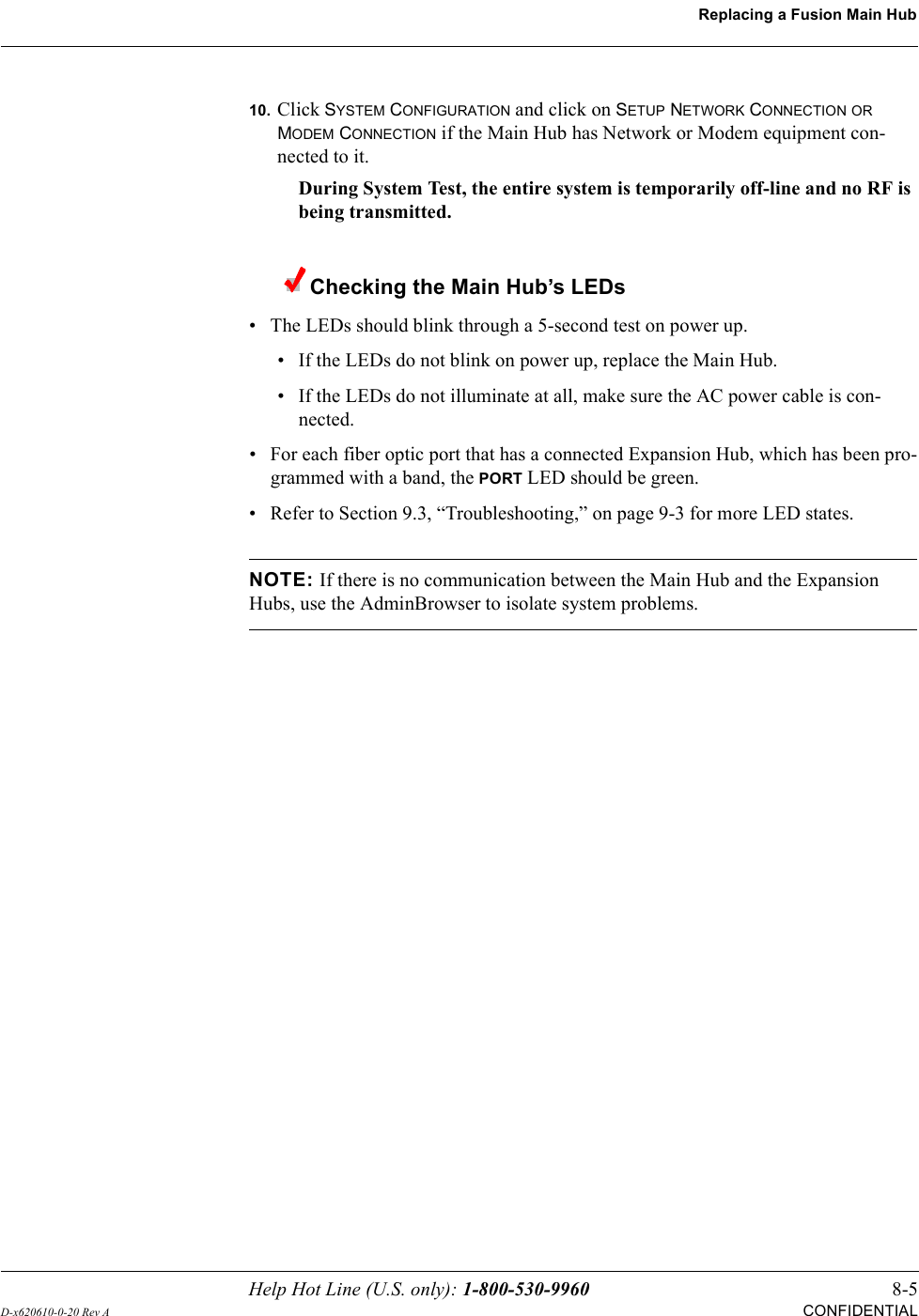
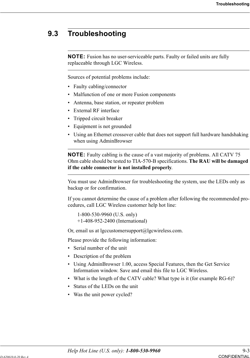

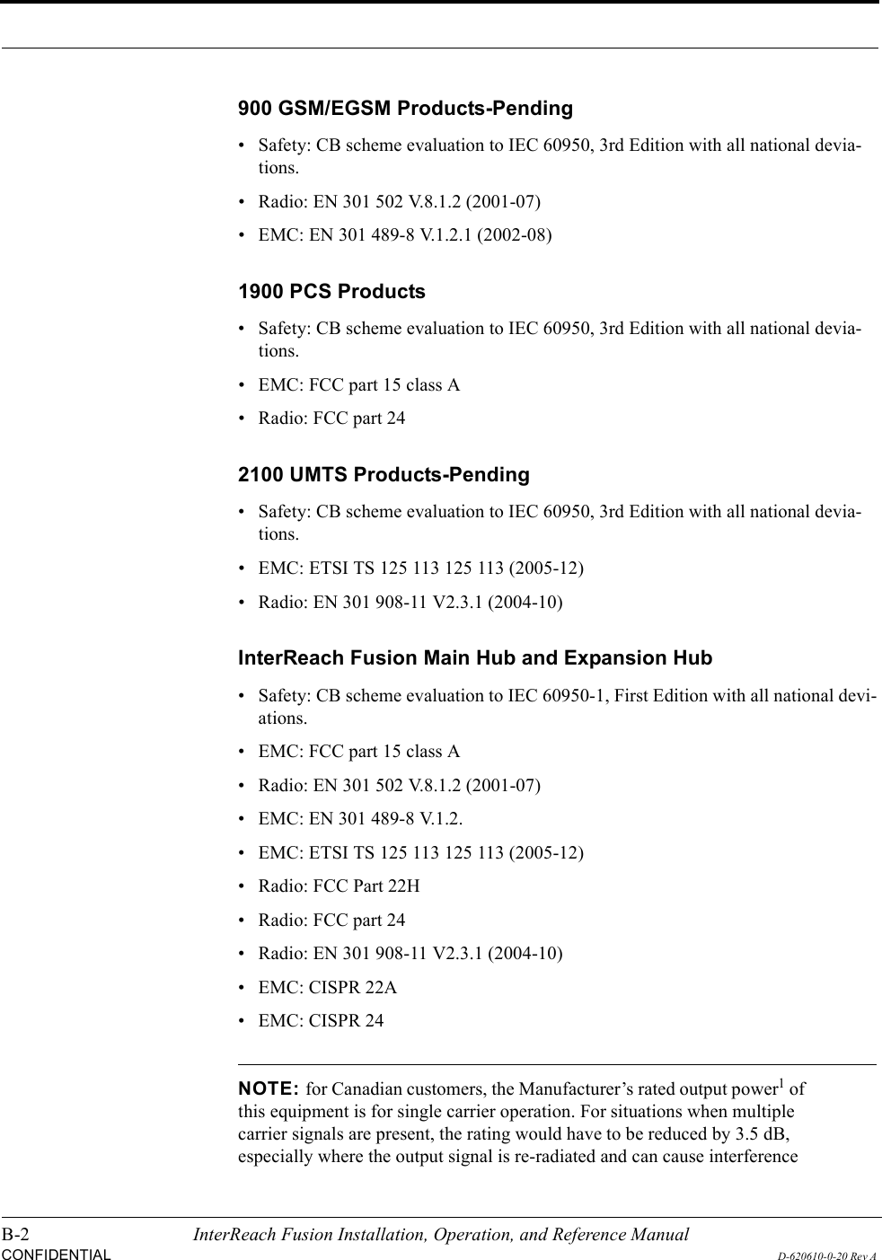
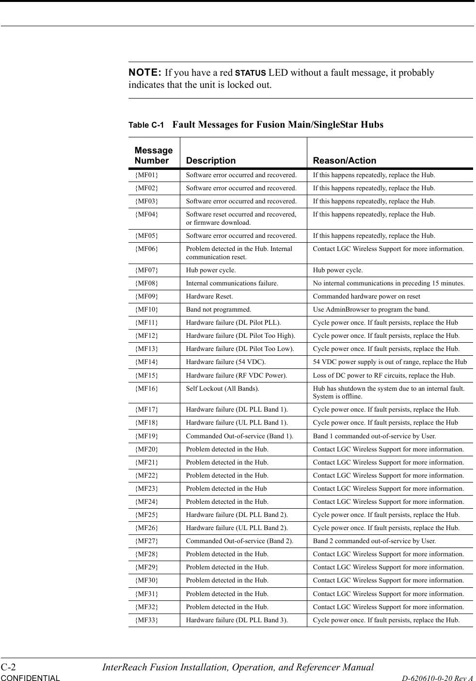
![C-10 InterReach Fusion Installation, Operation, and Referencer ManualCONFIDENTIALD-620610-0-20 Rev AC.5 Warning/Status Messages for Fusion Main/SingleStar HubsWarning MessagesWarnings alert you to conditions that indicate possible service impact. Warnings are displayed in the Messages pane in red lettering.Before addressing warnings, ensure that all faults are resolved. Take appropriate action to resolve the warnings, as indicated in the following tables.NOTE: AdminBrowser v0000007 or higher displays events (faults, warn-ings, or status messages) depending on your view preference. To change your view preference, refer to Section 3.3.2, “View Preference,” on page 3-10.Status MessagesStatus messages alert you to conditions that are important, but generally do not impact service. Status messages alert you to conditions that are important, but gener-ally do not impact service. Status messages are displayed in the Messages pane in blue lettering.NOTE: AdminBrowser v0000007 or higher displays events (faults, warn-ings, or status messages) depending on your view preference. To change your view preference, refer to Section 3.3.2, “View Preference,” on page 3-10.NOTE: The icons displayed in the system status tree assume that there are no other faults, warnings, or status present.In Table C-5, the message number is in the following form:[Mnn]/X where nn equals the message number, and X equals the default of either Sta-tus (S) or Warning (W).](https://usermanual.wiki/ADC-Telecommunications/FSN-809019-2.User-Manual-Part-Two/User-Guide-869356-Page-114.png)
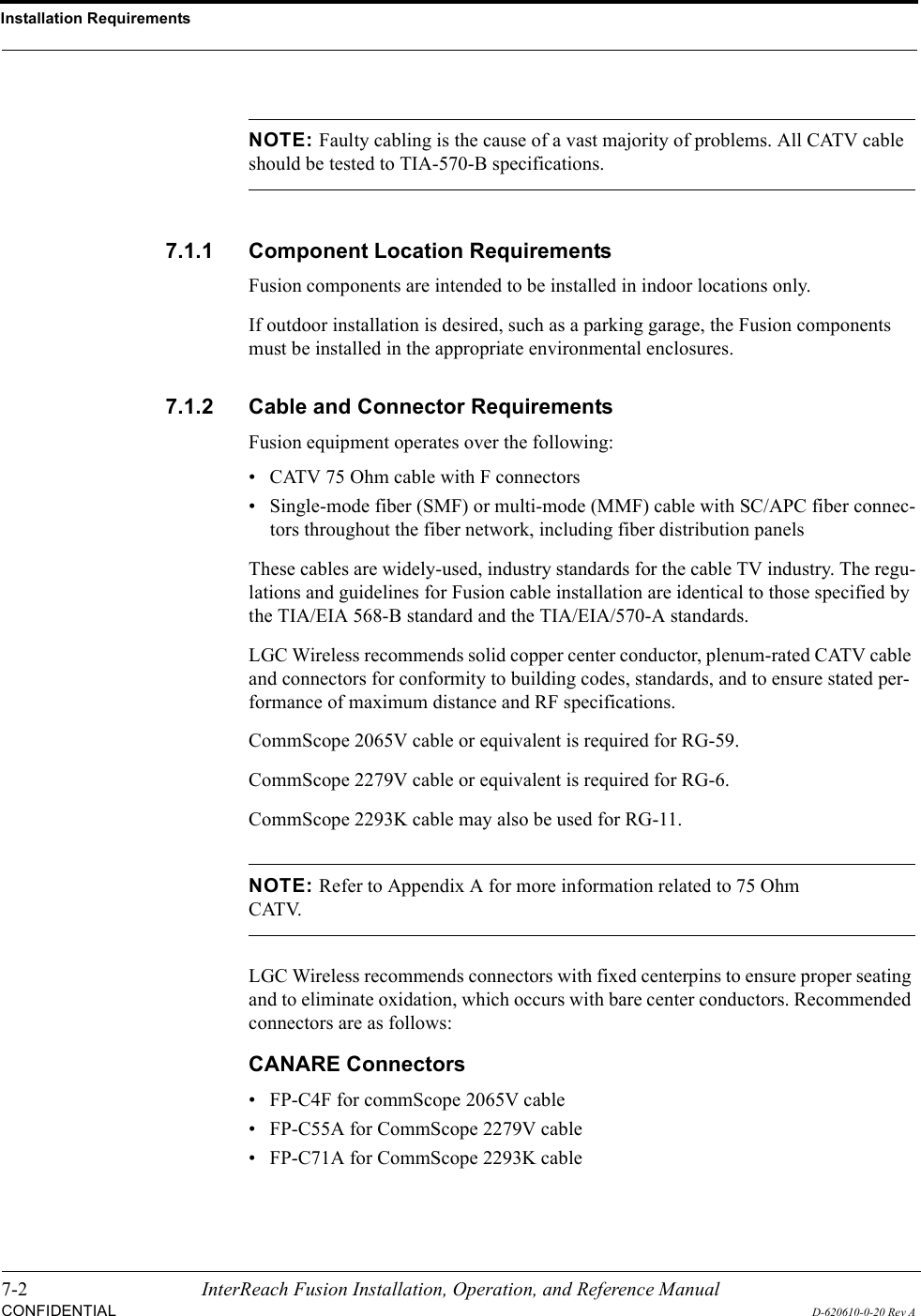
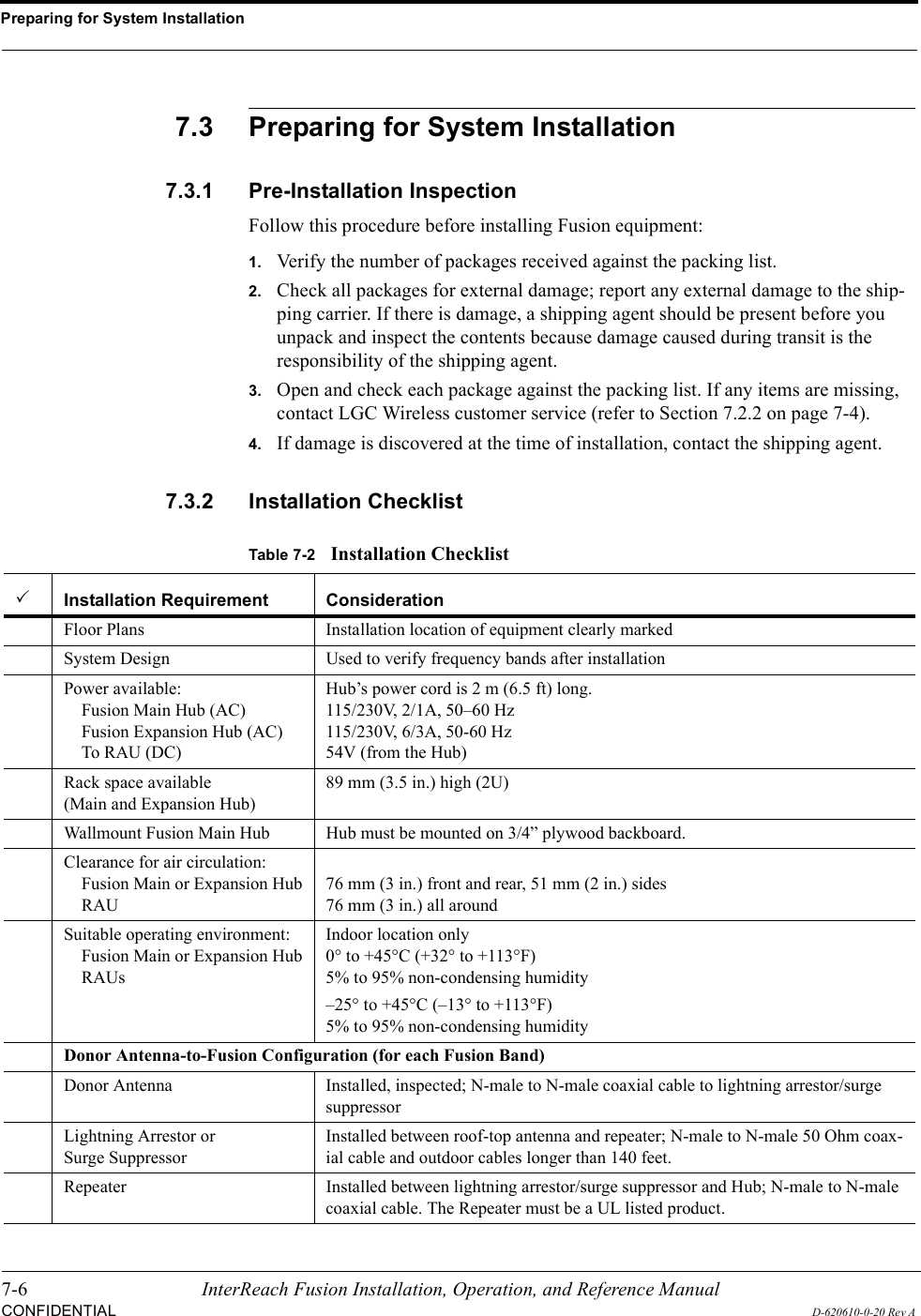
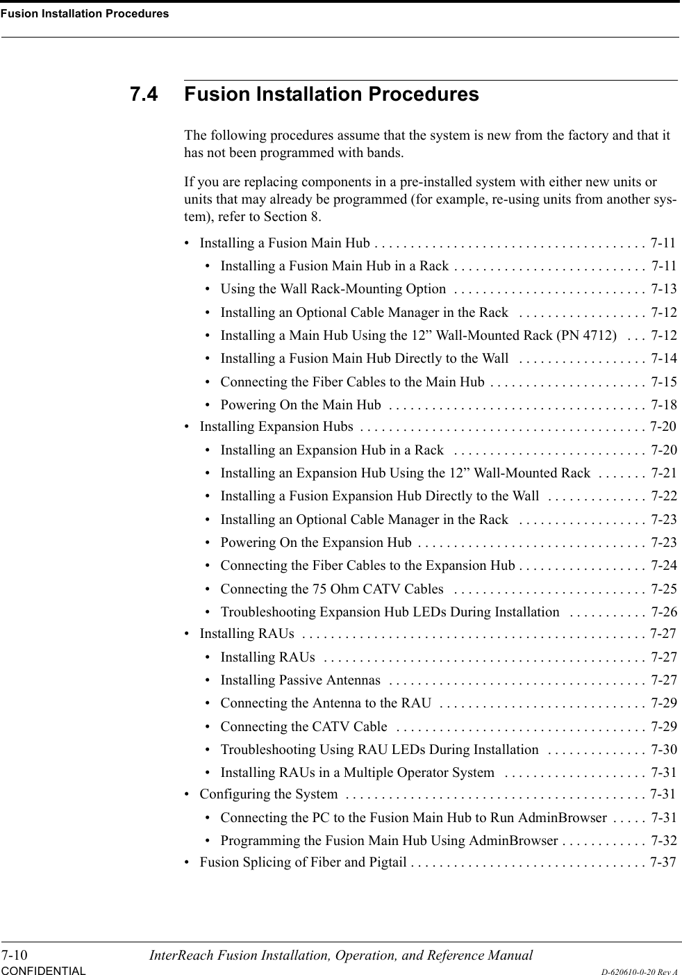
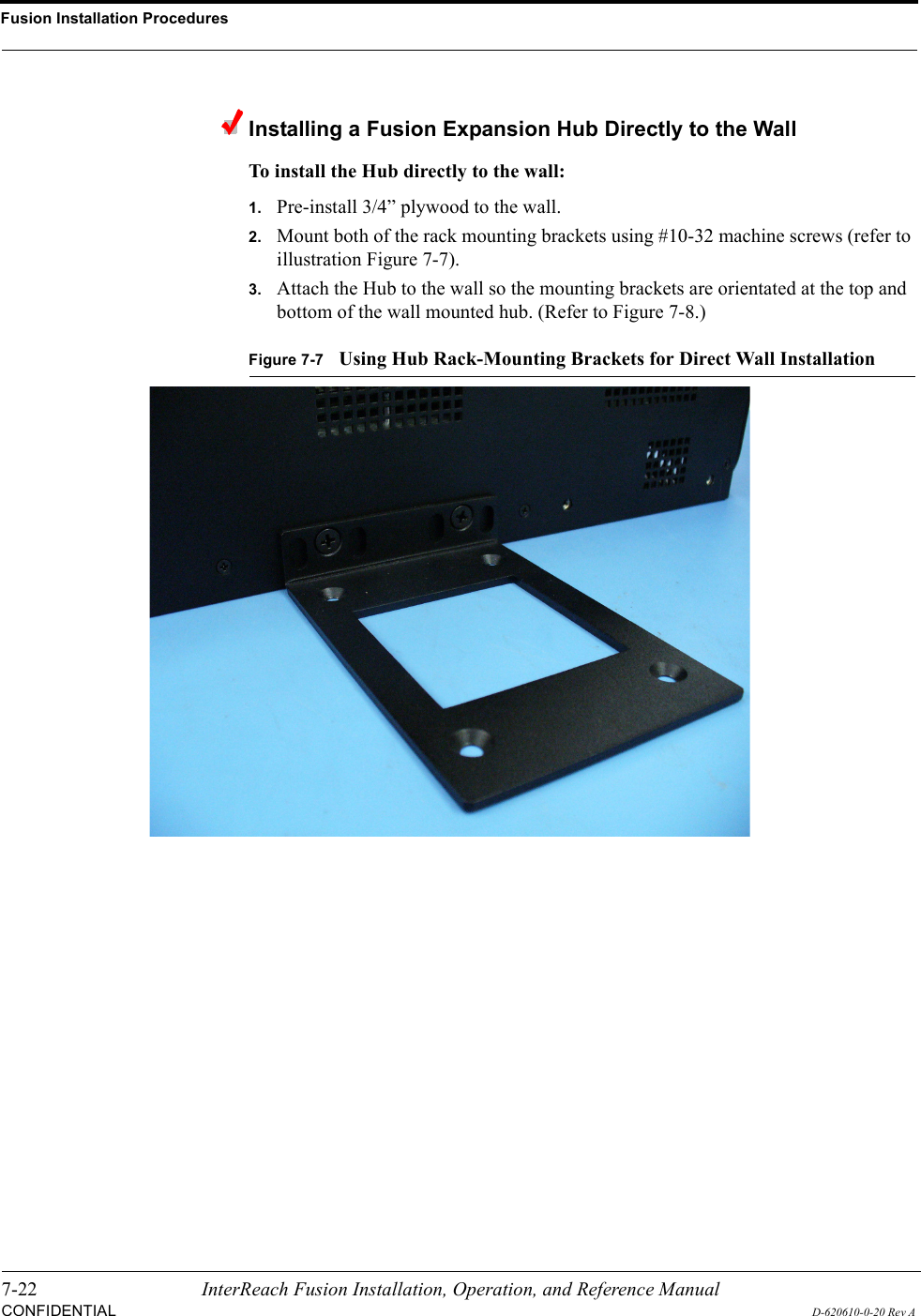
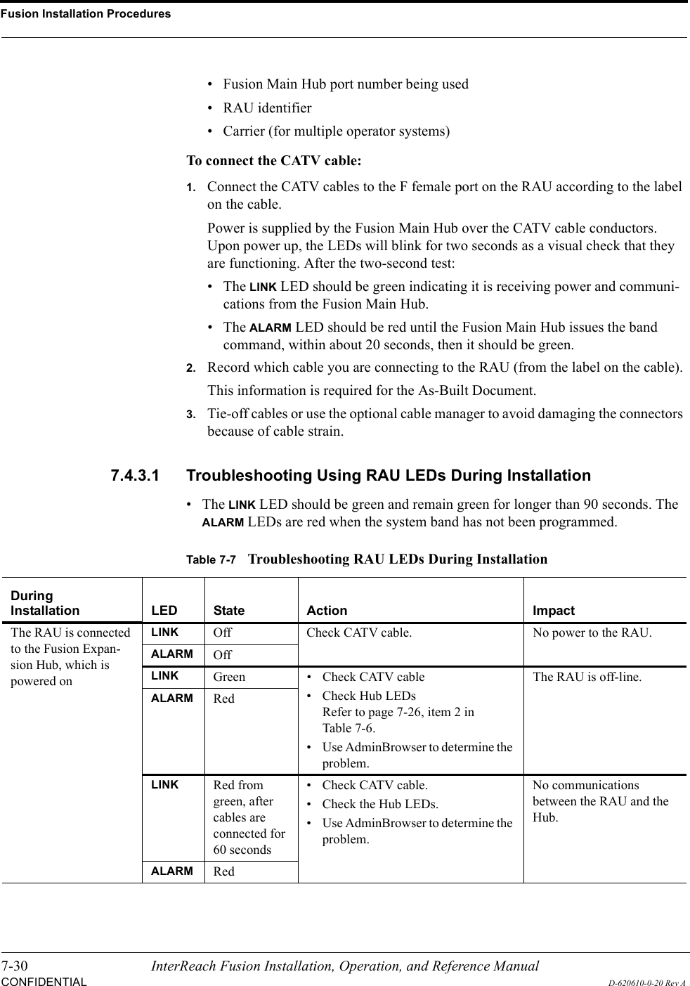
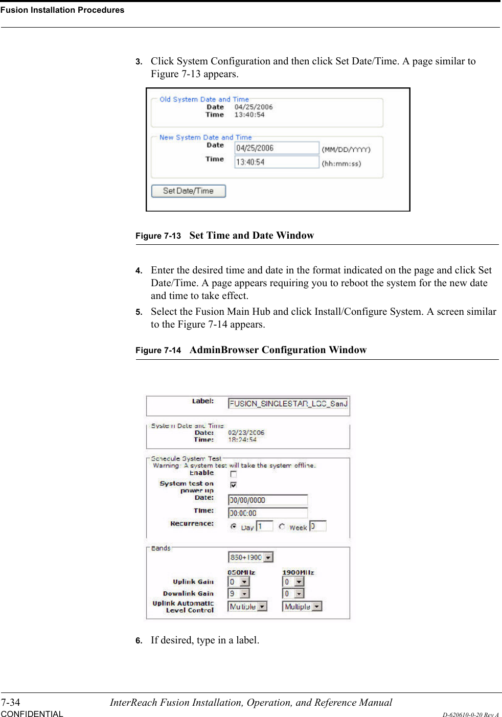
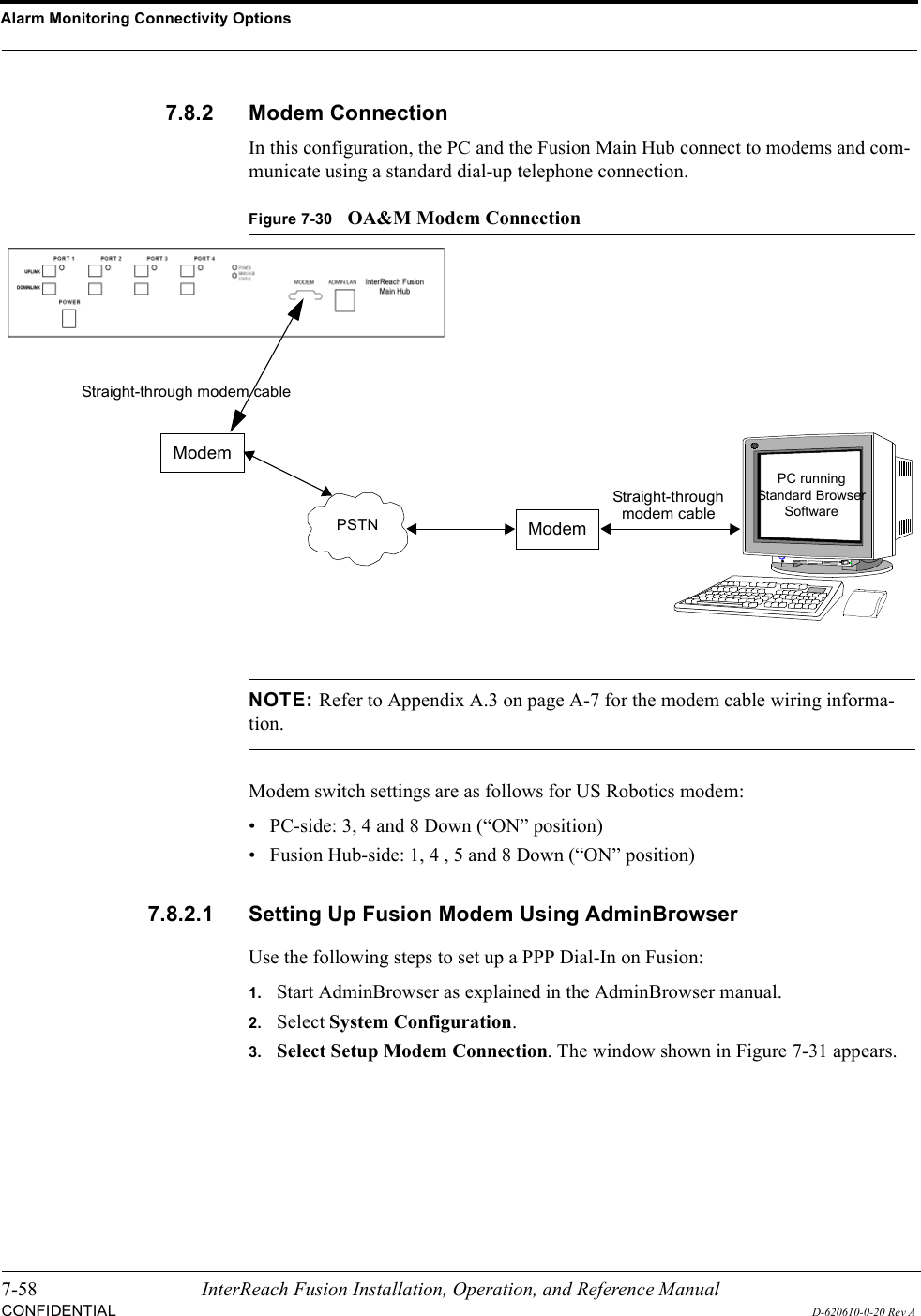
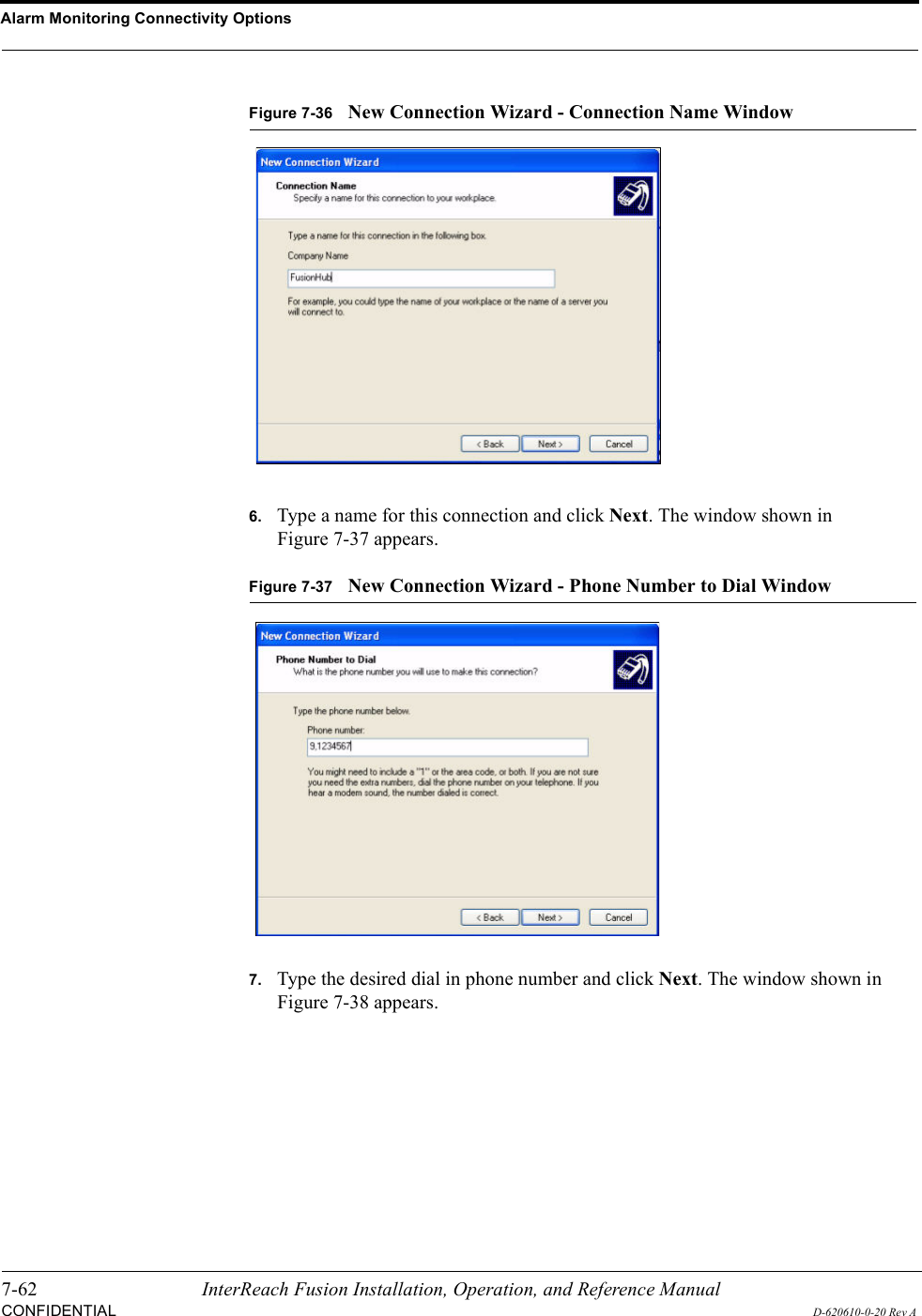
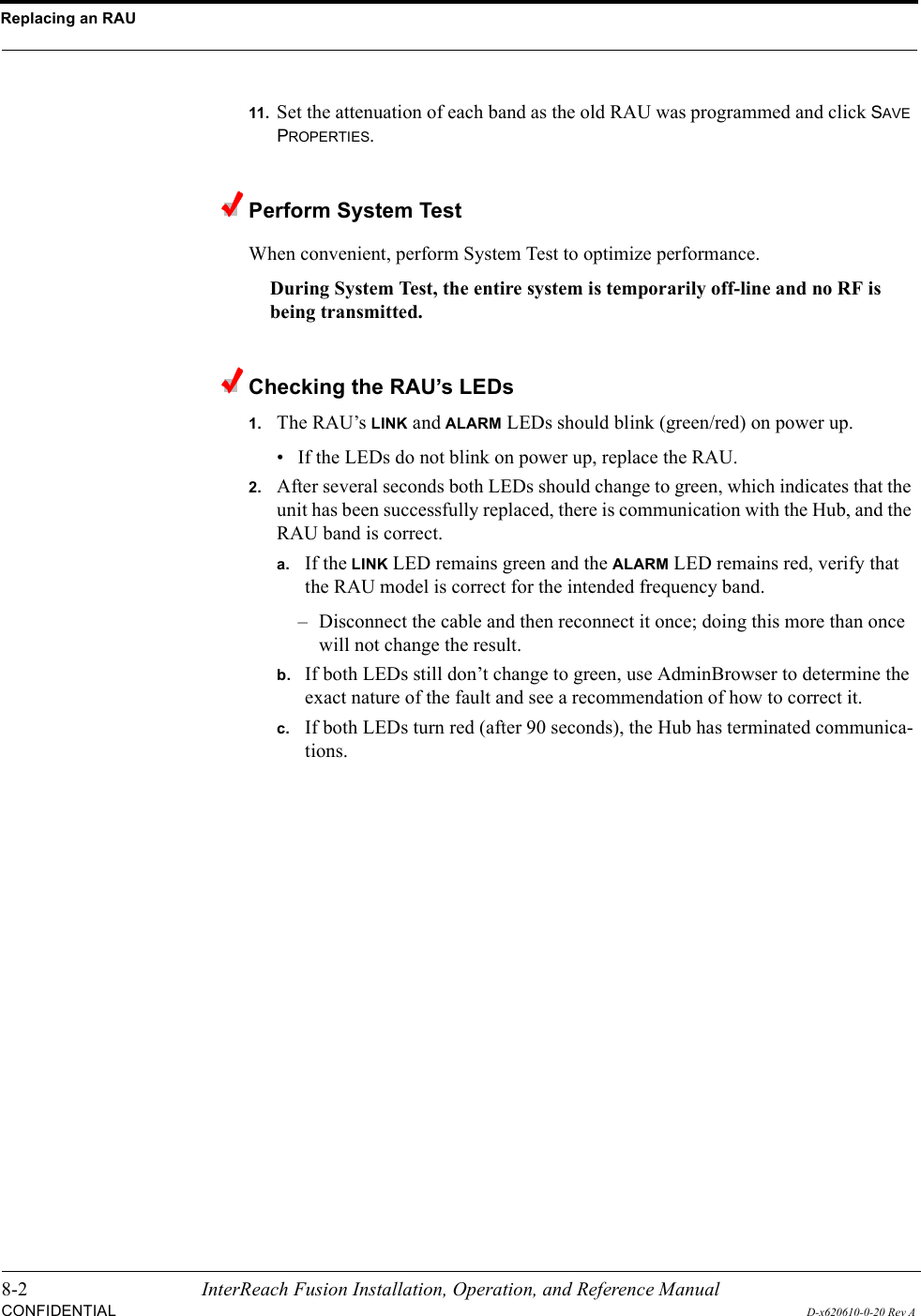
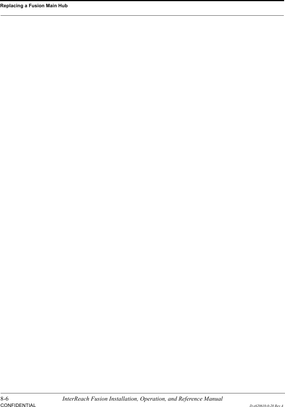
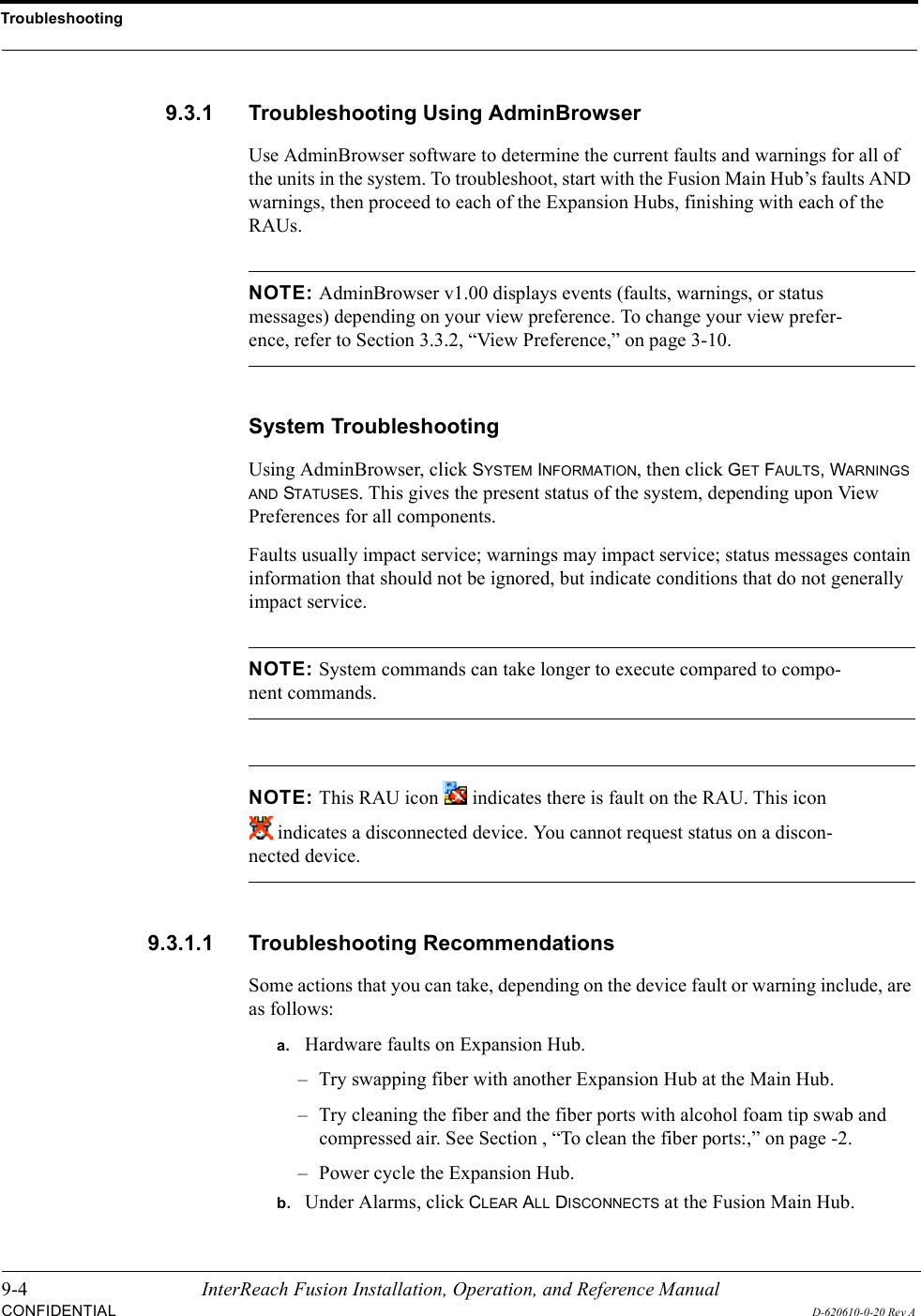
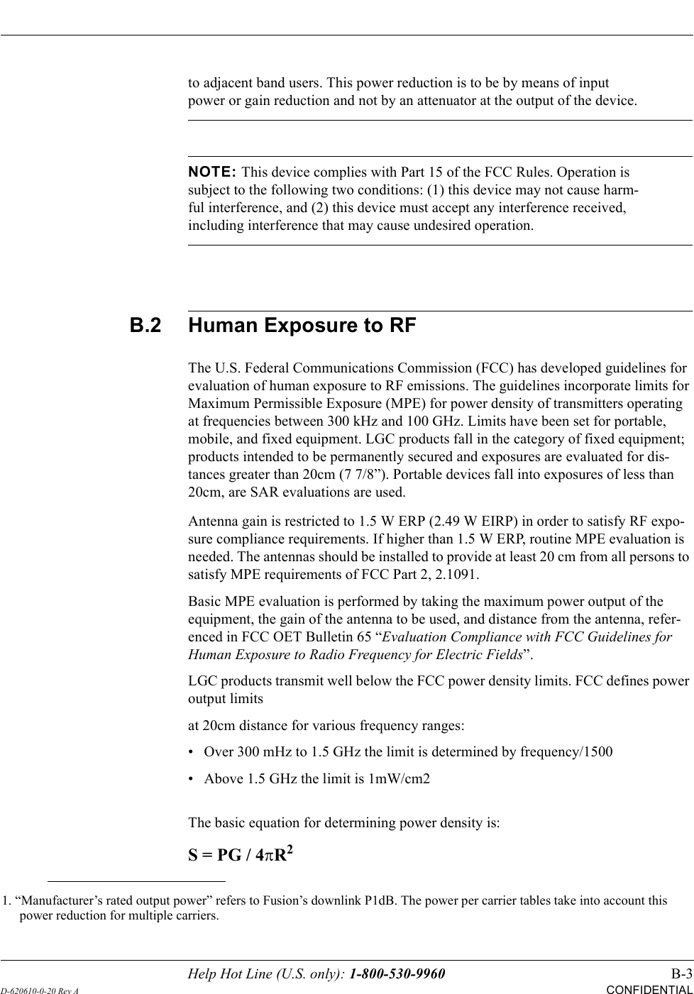
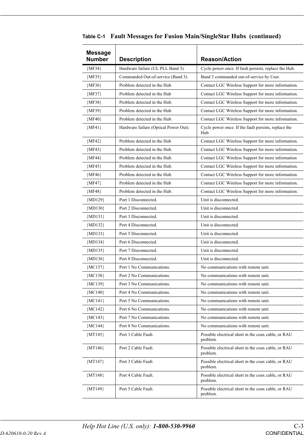
![Help Hot Line (U.S. only): 1-800-530-9960 C-11D-620610-0-20 Rev ACONFIDENTIALTable C-5Warnings/Status Messages for Fusion Main/SingleStar HubsMessage Number/Default Description Reason/Action[M01]/S Fan 1 failure. Check the fan for rotation, air flow blockage, and dust. Replace the Hub on high temperature warning.[M02]/S Fan 2 failure. Check the fan for rotation, air flow blockage, and dust. Replace the Hub on high temperature warning.[M03]/S 54 VDC Pwr Supply Fan failure. Check the fan for rotation, air flow blockage, and dust. Replace the Hub on high temperature warning.[M04]/W 5 VDC Monitor. DC power out of range, replace the Hub.[M05]/W 9 VDC Monitor. DC power out of range, replace the Hub.[M06]/W 54 VDC Monitor. DC power out of range, replace the Hub.[M07]/W 3 VDC Monitor. DC power out of range, replace the Hub.[M08]/W 12 VDC Monitor. DC power out of range, replace the Hub.[M09]/W Temperature High. Reduce ambient temperature, check for air flow blockage, fan rotation.[M10]/W -5 VDC Monitor. DC power is out of range, replace the Hub.[M11]/W High laser current. Output laser failure possible, replace the Hub when possi-ble.[M12]/W DL path loss is too high Replace the Hub.[M13]/S Low input optical (Port 1). Check the uplink fiber.[M14]/S Low input optical (Port 2). Check the uplink fiber.[M15]/S Low input optical (Port 3). Check the uplink fiber.[M16]/S Low input optical (Port 4). Check the uplink fiber.[M17]/S Hardware failure (Test Tone PLL Band 1).Unable to perform DL system test.[M18]/S Hardware failure (Test Tone Too High Band 1).Unable to perform DL system test.[M19]/S Hardware failure (Test Tone Too Low Band 1).Unable to perform DL system test.[M20]/W Overdrive limiter active (Band 1). Reduce input signal power to avoid potential component damage.[M21]/W CEMark limiter at maximum (Band 1).Reduce input signal power to avoid drop in system gain.[M22]/W No DL test tone (Band 1). Hub DL gain is low.[M23]/S No UL test tone (Band 1). Hub UL path gain is low.[M24]/S Problem detected in the system. Contact LGC Wireless Support for more information.[M25]/S Hardware failure (Test Tone PLL Band 2).Unable to perform DL system test. Replace the hub when possible.[M26]/S Hardware failure (Test Tone Too High Band 2).Unable to perform DL system test. Replace the hub when possible.[M27]/S Hardware failure (Test Tone Too Low Band 2).Unable to perform DL system test. Replace the hub when possible.[M28]/W Overdrive limiter active (Band 2). Reduce input signal power to avoid potential component damage.[M29]/W CEMark limiter at maximum (Band 2).Reduce input signal power to avoid drop in system gain.](https://usermanual.wiki/ADC-Telecommunications/FSN-809019-2.User-Manual-Part-Two/User-Guide-869356-Page-115.png)
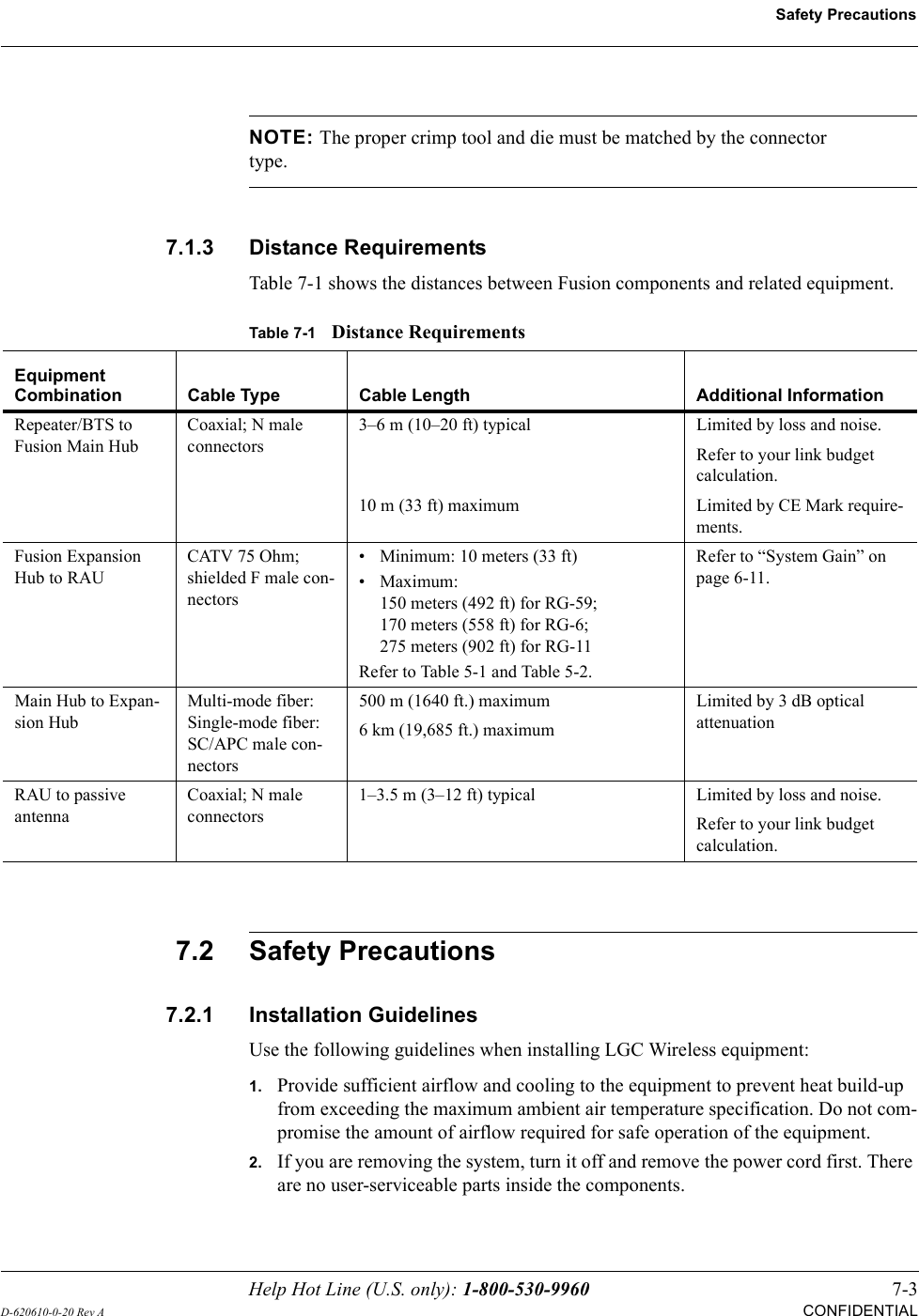
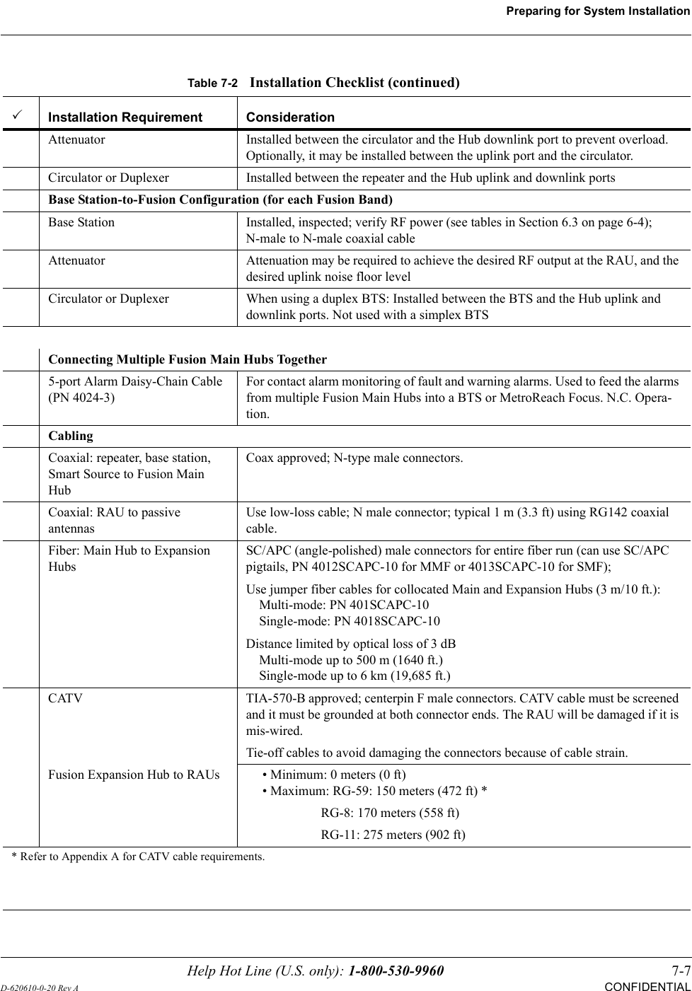
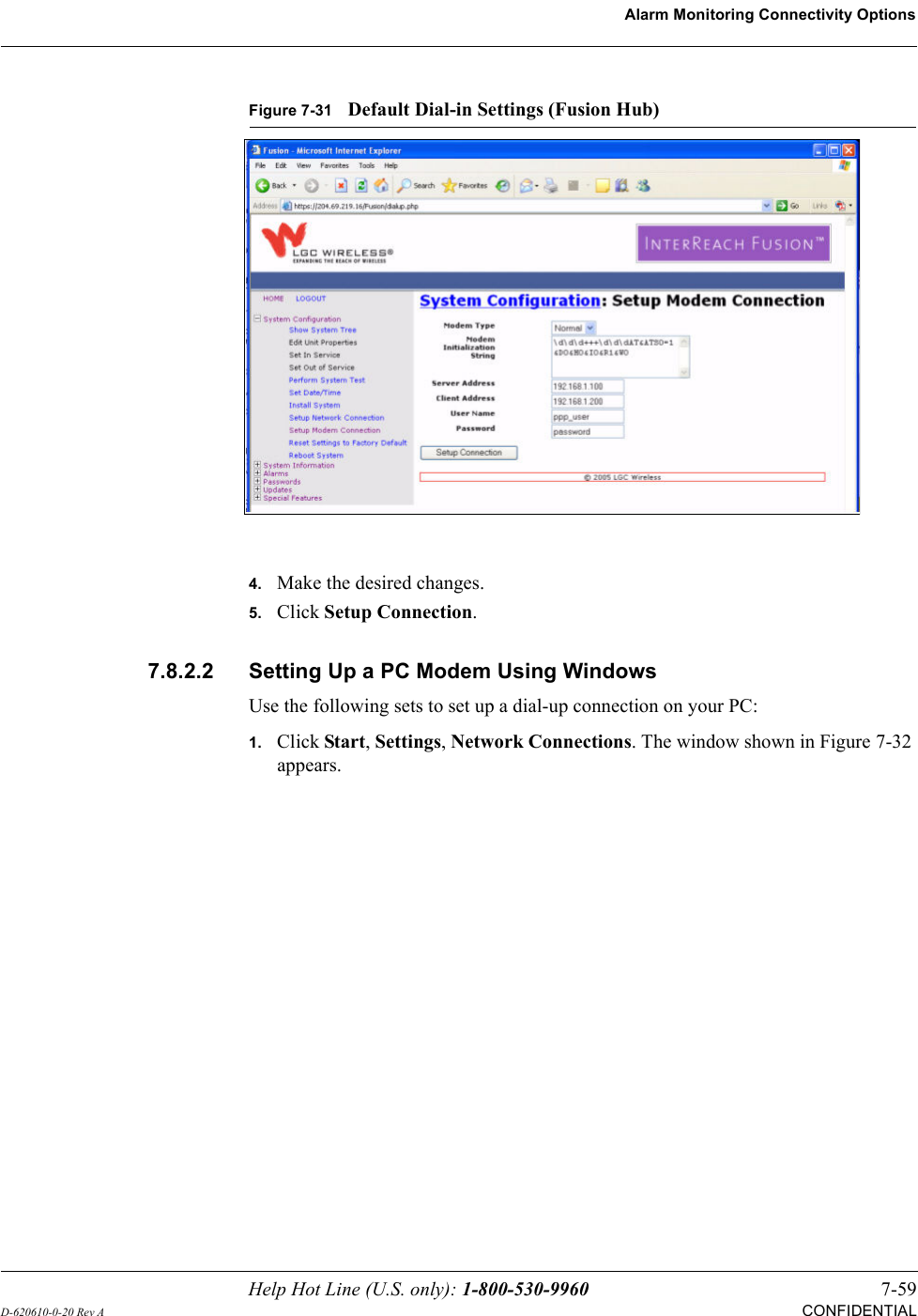
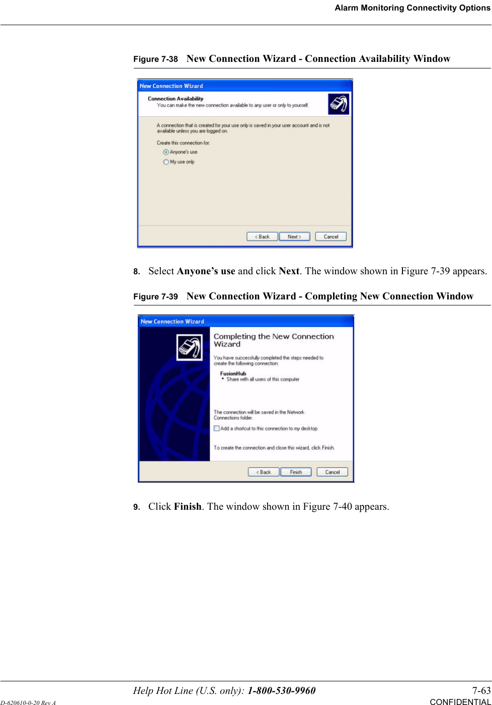
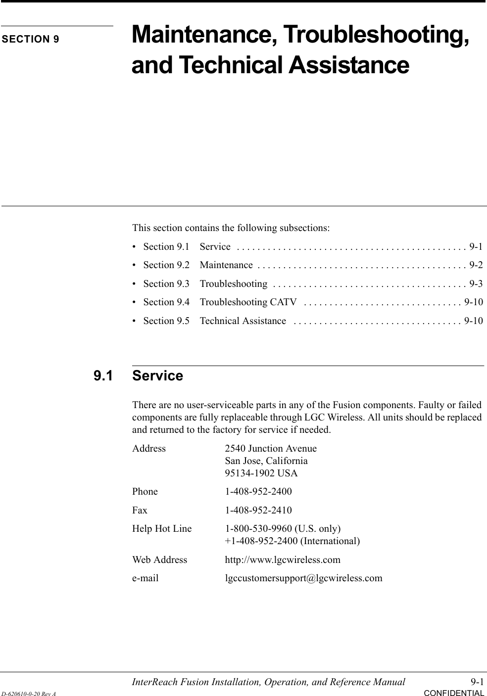
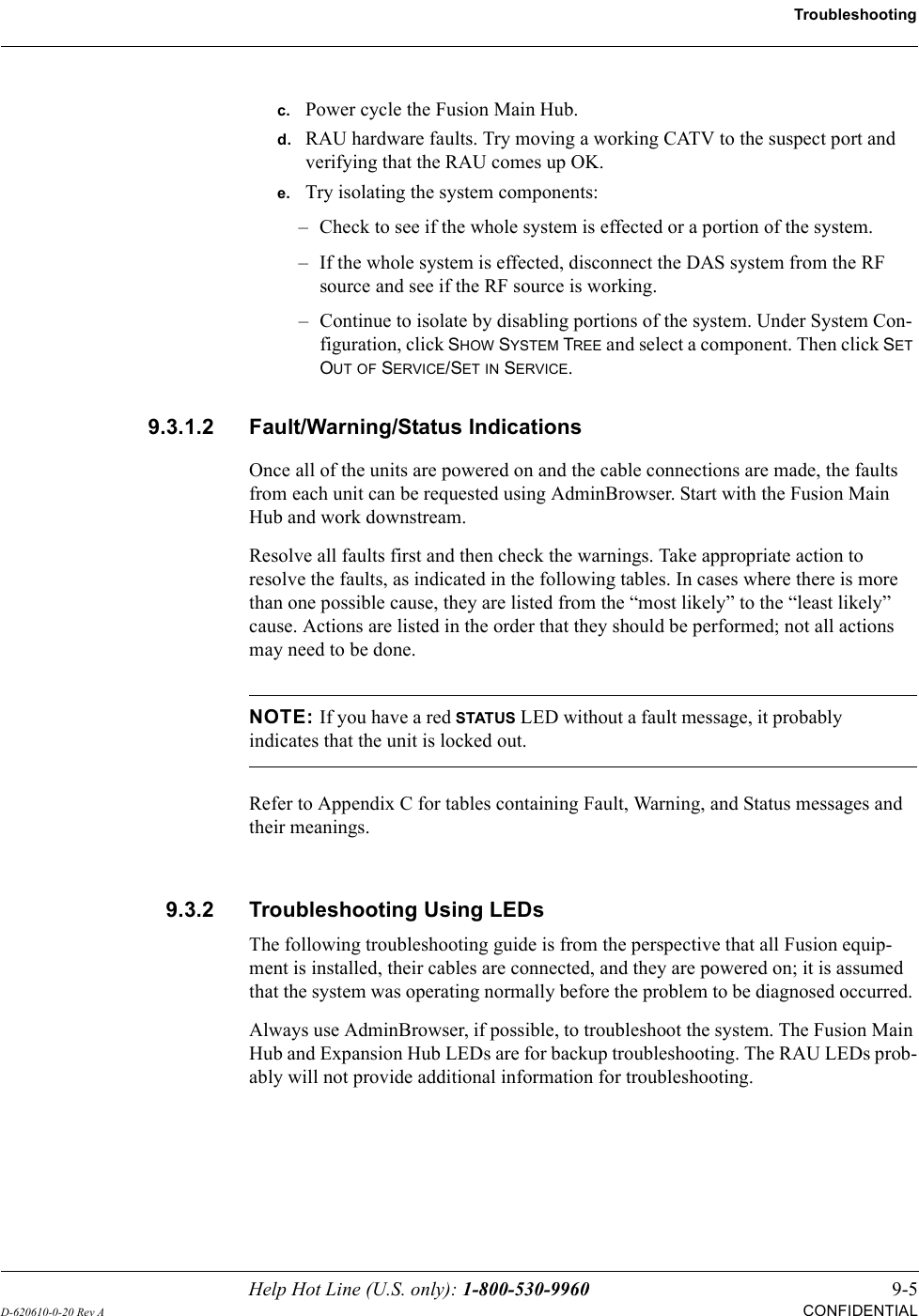
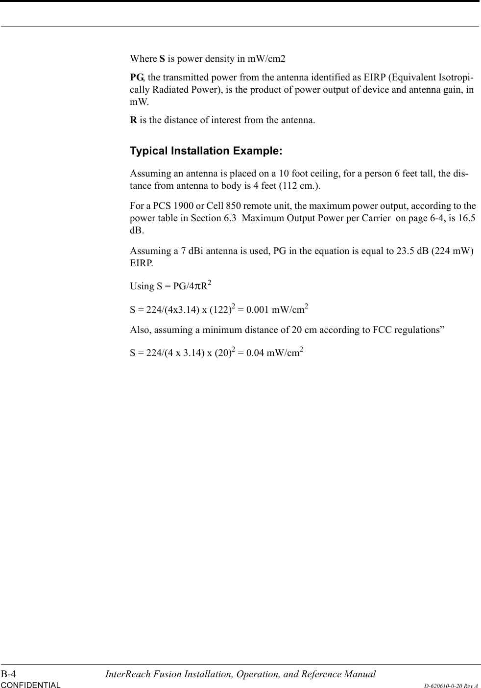
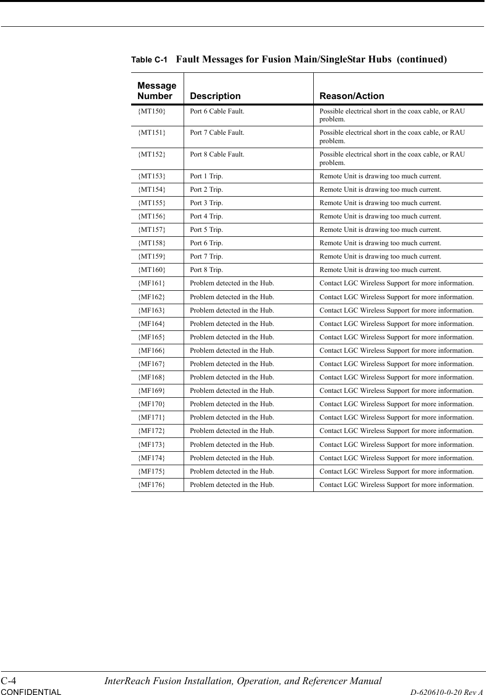
![C-12 InterReach Fusion Installation, Operation, and Referencer ManualCONFIDENTIALD-620610-0-20 Rev A[M30]/W No DL test tone (Band 2). Hub DL path gain is low.[M31]/S No UL test tone (Band 2). Hub UL path gain is low.[M32]/S Problem detected in the system. Contact LGC Wireless Support for more information.[M33]/S Hardware failure (Test Tone PLL Band 3).Unable to perform DL system test.[M34]/S Hardware failure (Test Tone Too High Band 3).Unable to perform DL system test.[M35]/S Hardware failure (Test Tone Too Low Band 3).Unable to perform DL system test.[M36]/W Overdrive limiter active (Band 3). Reduce input signal power to avoid potential component damage.[M37]/W CEMark limiter at maximum (Band 3).Reduce input signal power to avoid drop in system gain.[M38]/W No DL test tone (Band 3). Hub DL path gain is low.[M39]/S No UL test tone (Band 3). Hub UL path gain is low.[M40]/S Problem detected in the Hub. Contact LGC Wireless Support for more information.[M41]/W Port 1 No DL test tone (Band 1). Hub/Port DL path gain is low.[M42]/W Port 2 No DL test tone (Band 1). Hub/Port DL path gain is low.[M43]/W Port 3 No DL test tone (Band 1). Hub/Port DL path gain is low.[M44]/W Port 4 No DL test tone (Band 1). Hub/Port DL path gain is low.[M45]/W Port 5 No DL test tone (Band 1). Hub/Port DL path gain is low.[M46]/W Port 6 No DL test tone (Band 1). Hub/Port DL path gain is low.[M47]/W Port 7 No DL test tone (Band 1). Hub/Port DL path gain is low.[M48]/W Port 8 No DL test tone (Band 1). Hub/Port DL path gain is low.[M49]/W Port 1 No DL test tone (Band 2). Hub/Port DL path gain is low.[M50]/W Port 2 No DL test tone (Band 2). Hub/Port DL path gain is low.[M51]/W Port 3 No DL test tone (Band 2). Hub/Port DL path gain is low.[M52]/W Port 4 No DL test tone (Band 2). Hub/Port DL path gain is low.[M53]/W Port 5 No DL test tone (Band 2). Hub/Port DL path gain is low.[M54]/W Port 6 No DL test tone (Band 2). Hub/Port DL path gain is low.[M55]/W Port 7 No DL test tone (Band 2). Hub/Port DL path gain is low.[M56]/W Port 8 No DL test tone (Band 2). Hub/Port DL path gain is low.[M57]/W Port 1 No DL test tone (Band 3). Hub/Port DL path gain is low.[M58]/W Port 2 No DL test tone (Band 3). Hub/Port DL path gain is low.[M59]/W Port 3 No DL test tone (Band 3). Hub/Port DL path gain is low.[M60]/W Port 4 No DL test tone (Band 3). Hub/Port DL path gain is low.[M61]/W Port 5 No DL test tone (Band 3). Hub/Port DL path gain is low.[M62]/W Port 6 No DL test tone (Band 3). Hub/Port DL path gain is low.[M63]/W Port 7 No DL test tone (Band 3). Hub/Port DL path gain is low.[M64]/W Port 8 No DL test tone (Band 3). Hub/Port DL path gain is low.[M65]/S No UL test tone (Band 1). Hub/Port UL path gain is low.Table C-5Warnings/Status Messages for Fusion Main/SingleStar Hubs Message Number/Default Description Reason/Action](https://usermanual.wiki/ADC-Telecommunications/FSN-809019-2.User-Manual-Part-Two/User-Guide-869356-Page-116.png)
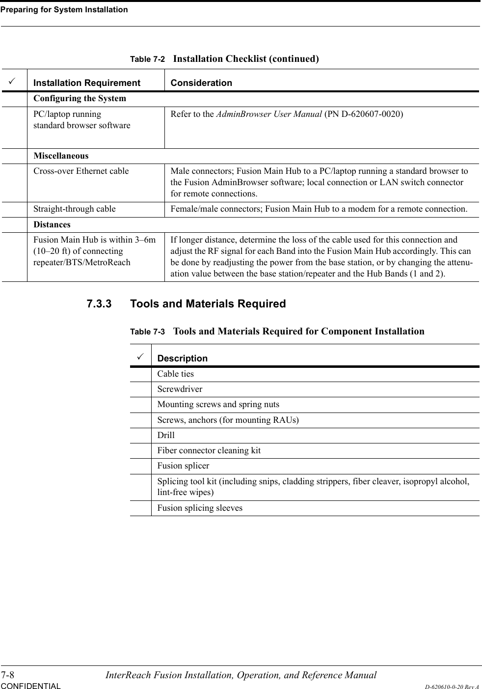
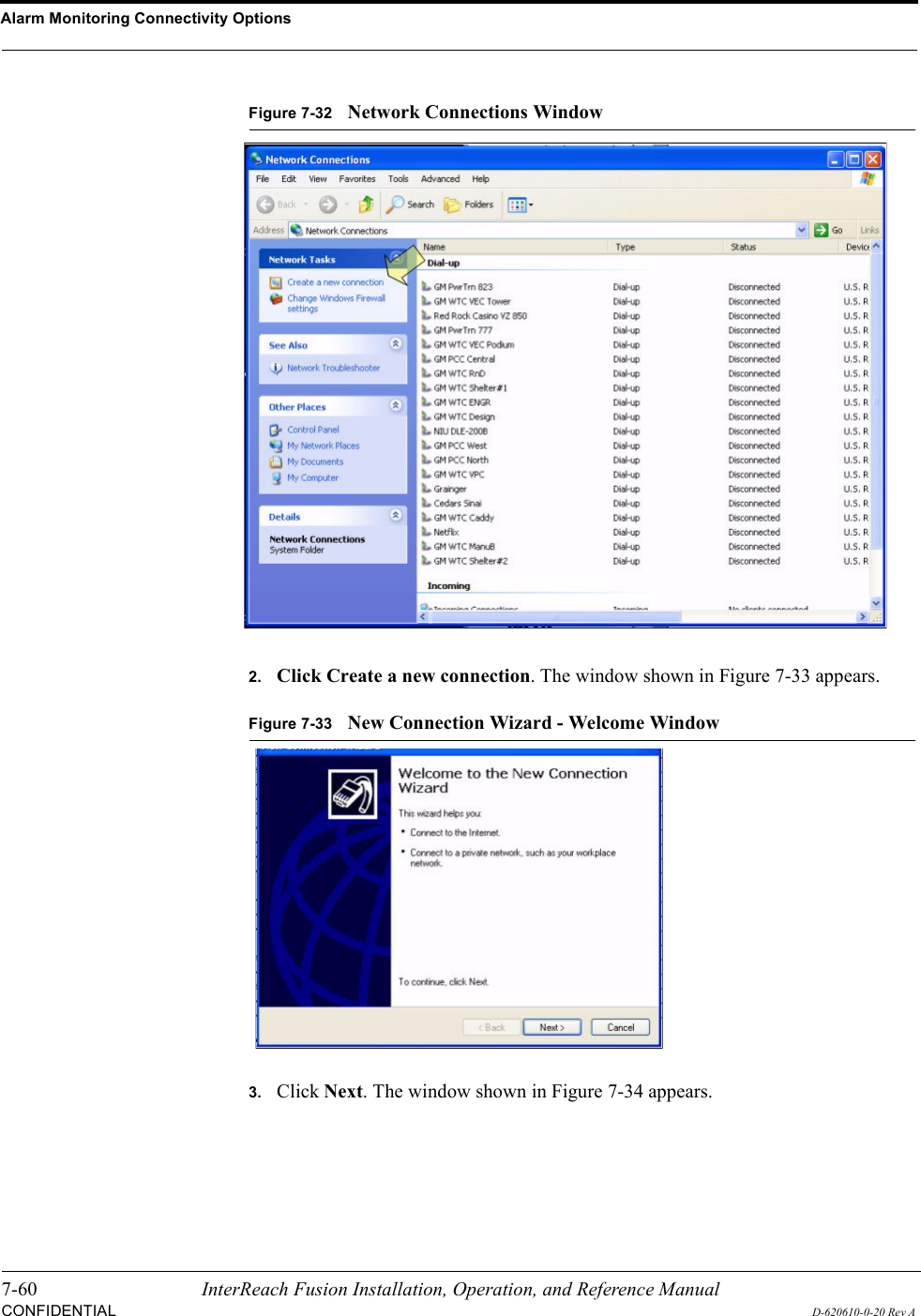
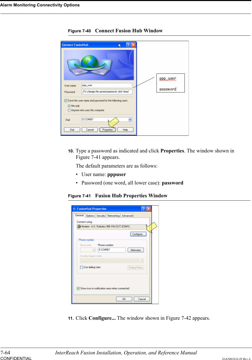
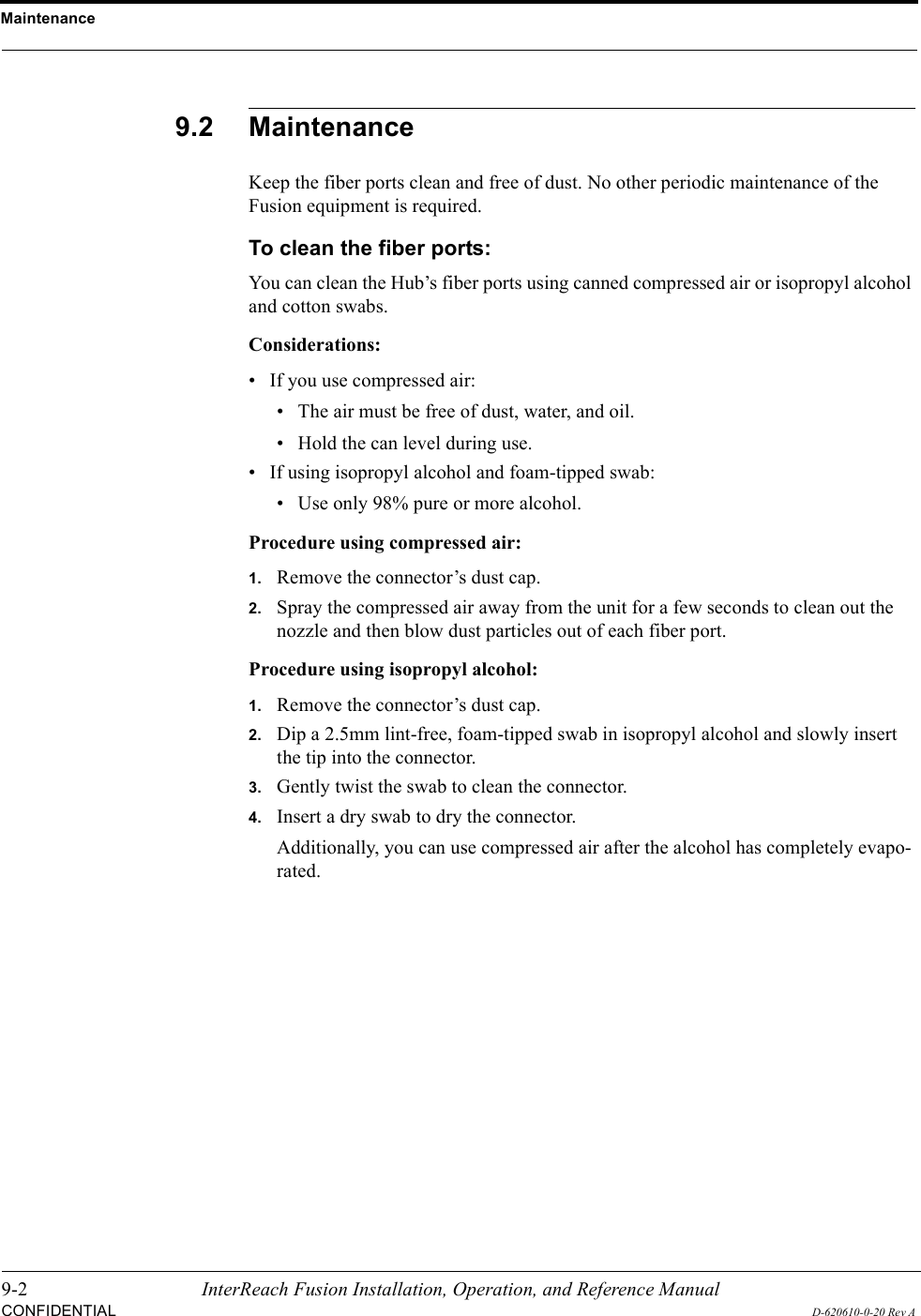
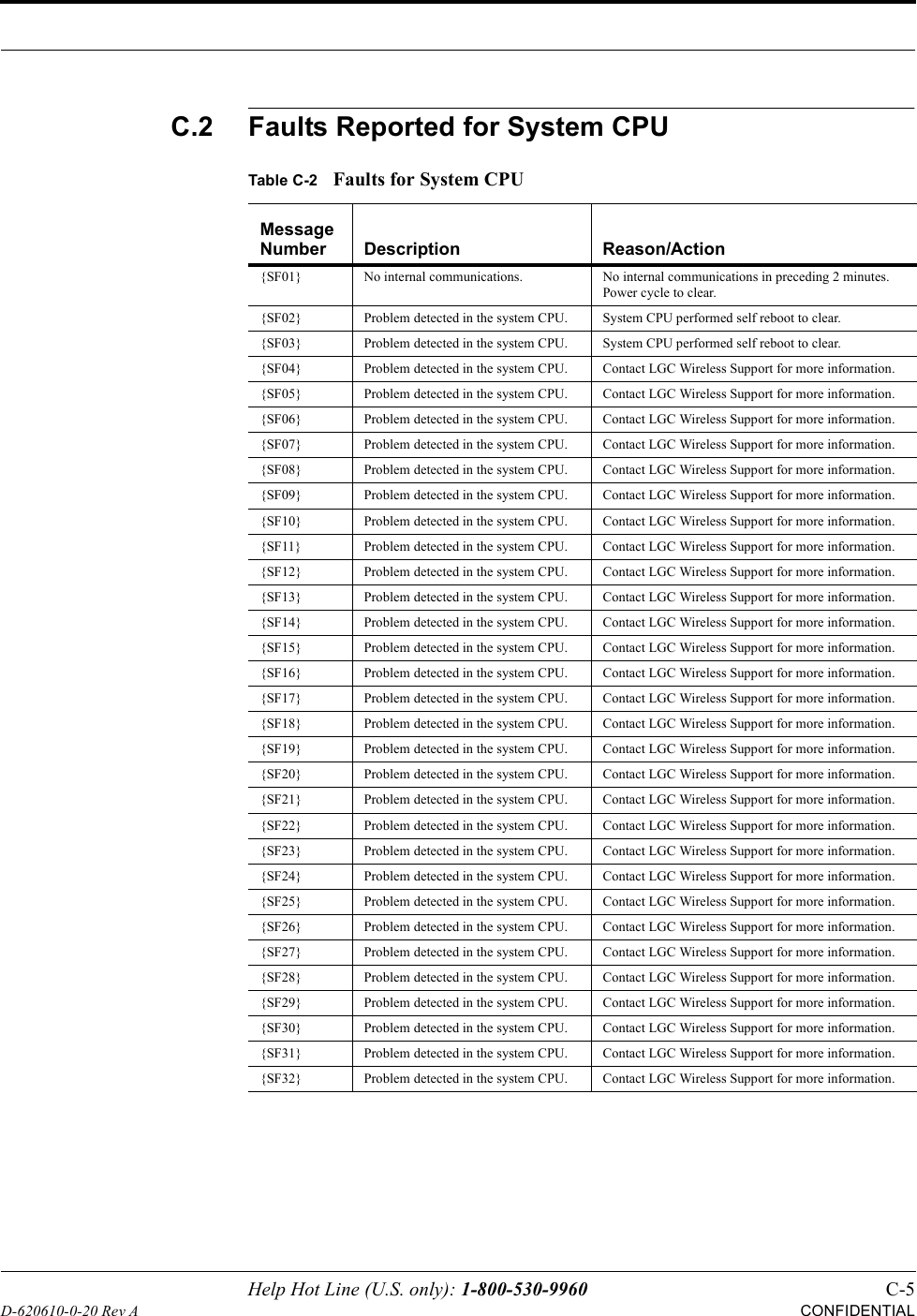
![Help Hot Line (U.S. only): 1-800-530-9960 C-13D-620610-0-20 Rev ACONFIDENTIAL[M66]/S Problem detected in the Hub. Contact LGC Wireless Support for more information.[M67]/S Problem detected in the Hub. Contact LGC Wireless Support for more information.[M68]/S No UL test tone (Port 4/Band 1). Hub/Port UL path gain is low.[M69]/S No UL test tone (Band 2). Hub/Port UL path gain is low.[M70]/S No UL test tone (Port 2/Band 2). Hub/Port UL path gain is low.[M71]/S No UL test tone (Port 3/Band 2). Hub/Port UL path gain is low.[M72]/S No UL test tone (Port 4/Band 2). Hub/Port UL path gain is low.[M73]/S No UL test tone (Band 3). Hub/Port UL path gain is low.[M74]/S No UL test tone (Port 2/Band 3). Hub/Port UL path gain is low.[M75]/S No UL test tone (Port 3/Band 3). Hub/Port UL path gain is low.[M76]/S No UL test tone (Port 4/Band 3). Hub/Port UL path gain is low.[M77]/S Problem detected in the Hub. Contact LGC Wireless Support for more information.[M78]/S Problem detected in the Hub. Contact LGC Wireless Support for more information.[M79]/S Problem detected in the Hub. Contact LGC Wireless Support for more information.[M80]/S Problem detected in the Hub. Contact LGC Wireless Support for more information.[M81]/W Port 1 DL path loss is high. If the problem is on more than one port, replace the Hub. Switch the cable connection to a different hub port until the Hub can be replaced.[M82]/W Port 2 DL path loss is high. If the problem is on more than one port, replace the Hub. Switch the cable connection to a different hub port until the Hub can be replaced.[M83]/W Port 3 DL path loss is high. If the problem is on more than one port, replace the Hub. Switch the cable connection to a different hub port until the Hub can be replaced.[M84]/W Port 4 DL path loss is high. If the problem is on more than one port, replace the Hub. Switch the cable connection to a different hub port until the Hub can be replaced.[M85]/W Port 5 DL path loss is high. If the problem is on more than one port, replace the Hub. Switch the cable connection to a different hub port until the Hub can be replaced.[M86]/W Port 6 DL path loss is high. If the problem is on more than one port, replace the Hub. Switch the cable connection to a different hub port until the Hub can be replaced.[M87]/W Port 7 DL path loss is high. If the problem is on more than one port, replace the Hub. Switch the cable connection to a different hub port until the Hub can be replaced.[M88]/W Port 8 DL path loss is high. If the problem is on more than one port, replace the Hub. Switch the cable connection to a different hub port until the Hub can be replaced.[M89]/W Port 1 UL path loss is high. Check the cable for high RF loss. Switch the cable connec-tion to a different hub port. If the problem on more than one port, replace the Hub, otherwise replace the RAU.[M90]/W Port 2 UL path loss is high. Check the cable for high RF loss. Switch the cable connec-tion to a different hub port. If the problem is on more than one port, replace the Hub, otherwise replace the RAU.[M91]/W Port 3 UL path loss is high. Check the cable for high RF loss. Switch the cable connec-tion to a different hub port. If the problem is on more than one port, replace the Hub, otherwise replace the RAU.Table C-5Warnings/Status Messages for Fusion Main/SingleStar Hubs Message Number/Default Description Reason/Action](https://usermanual.wiki/ADC-Telecommunications/FSN-809019-2.User-Manual-Part-Two/User-Guide-869356-Page-117.png)
![C-14 InterReach Fusion Installation, Operation, and Referencer ManualCONFIDENTIALD-620610-0-20 Rev A[M92]/W Port 4 UL path loss is high. Check the cable for high RF loss. Switch the cable connec-tion to a different hub port. If the problem is on more than one port, replace the Hub, otherwise replace the RAU.[M93]/W Port 5 UL path loss is high. Check the cable for high RF loss. Switch the cable connec-tion to a different hub port. If the problem is on more than one port, replace the Hub, otherwise replace the RAU.[M94]/W Port 6 UL path loss is high. Check the cable for high RF loss. Switch the cable connec-tion to a different hub port. If the problem is on more than one port, replace the Hub, otherwise replace the RAU.[M95]/W Port 7 UL path loss is high. Check the cable for high RF loss. Switch the cable connec-tion to a different hub port. If the problem is on more than one port, replace the Hub, otherwise replace the RAU.[M96]/W Port 8 UL path loss is high. Check the cable for high RF loss. Switch the cable connec-tion to a different hub port. If the problem is on more than one port, replace the Hub, otherwise replace the RAU.[M97]/W Port 1 UL path exceeds maximum gain.If the problem is common to more than one port, replace the Hub, otherwise check the RAU.[M98]/W Port 2 UL path exceeds maximum gain.If the problem is common to more than one port, replace the Hub, otherwise check the RAU.[M99]/W Port 2 UL path exceeds maximum gain.If the problem is common to more than one port, replace the Hub, otherwise check the RAU.[M100]/W Port 2 UL path exceeds maximum gain.If the problem is common to more than one port, replace the Hub, otherwise check the RAU.[M101]/W Port 2 UL path exceeds maximum gain.If the problem is common to more than one port, replace the Hub, otherwise check the RAU.[M102]/W Port 2 UL path exceeds maximum gain.If the problem is common to more than one port, replace the Hub, otherwise check the RAU.[M103]/W Port 2 UL path exceeds maximum gain.If the problem is common to more than one port, replace the Hub, otherwise check the RAU.[M104]/W Port 8 UL path exceeds maximum gain.If the problem is common to more than one port, replace the Hub, otherwise check the RAU.[M105]/W Port 1 54 VDC Power Enabled. Caution: Port 54 VDC power may be present at the output.[M106]/W Port 2 54 VDC Power Enabled. Caution: Port 54 VDC power may be present at the output.[M107]/W Port 3 54 VDC Power Enabled. Caution: Port 54 VDC power may be present at the output.[M108]/W Port 4 54 VDC Power Enabled. Caution: Port 54 VDC power may be present at the output.[M109]/W Port 5 54 VDC Power Enabled. Caution: Port 54 VDC power may be present at the output.[M110]/W Port 6 54 VDC Power Enabled. Caution: Port 54 VDC power may be present at the output.[M111]/W Port 7 54 VDC Power Enabled. Caution: Port 54 VDC power may be present at the output.[M112]/W Port 8 54 VDC Power Enabled. Caution: Port 54 VDC power may be present at the output.Table C-5Warnings/Status Messages for Fusion Main/SingleStar Hubs Message Number/Default Description Reason/Action](https://usermanual.wiki/ADC-Telecommunications/FSN-809019-2.User-Manual-Part-Two/User-Guide-869356-Page-118.png)
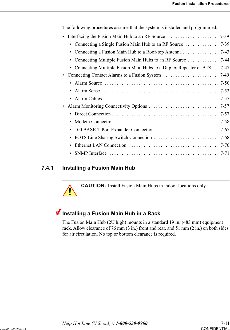
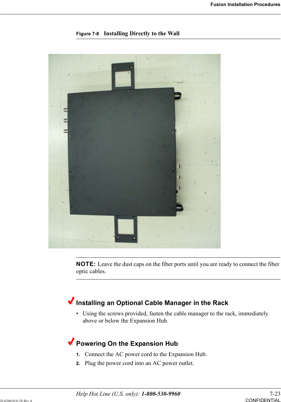
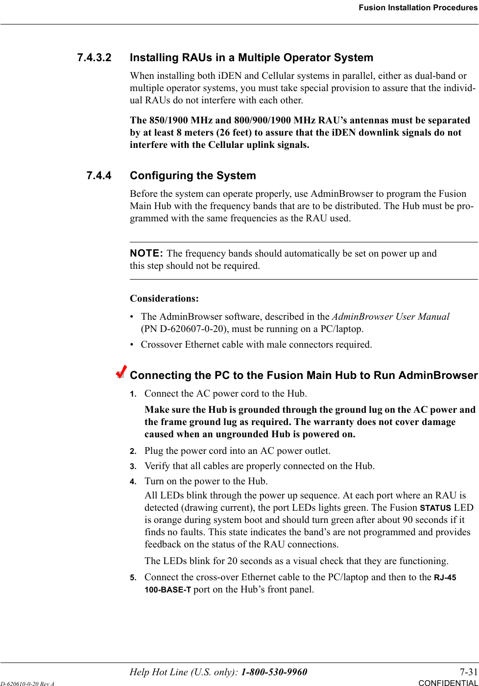
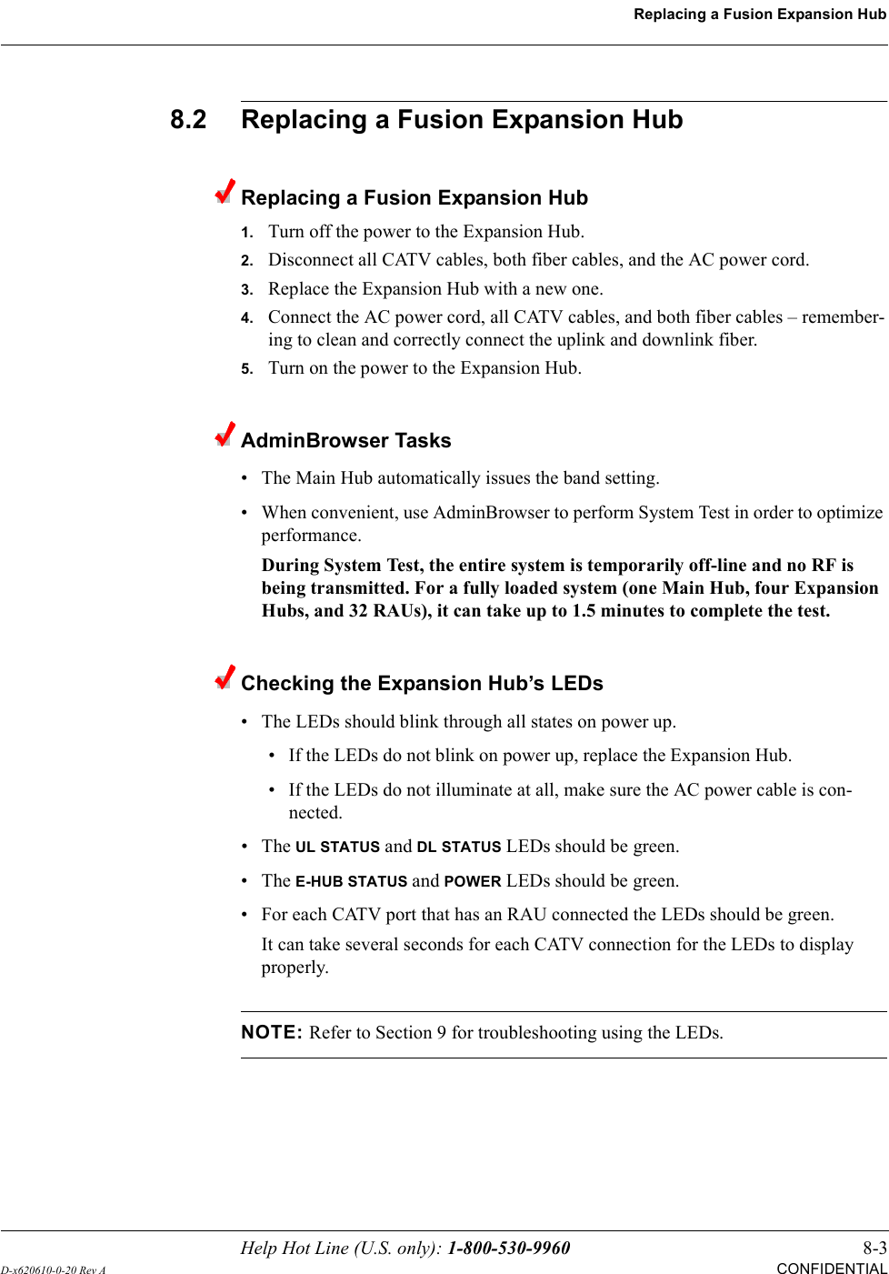
![Help Hot Line (U.S. only): 1-800-530-9960 C-15D-620610-0-20 Rev ACONFIDENTIALC.6 Warning/Status Messages for System CPUsIn Table C-6, the message number is in the following form:[Snn]/X where nn equals the message number, and X equals the default of either Sta-tus (S) or Warning (W).Table C-6Warning/Status Messages for System CPUsMessage Number/Default Description Reason/Action[S01]/W Alarm Input 1. Check equipment connected to alarm input 1.[S02]/W Alarm Input 2. Check equipment connected to alarm input 2.[S03]/W Alarm Input 3. Check equipment connected to alarm input 3.[S04]/S Problem detected in the system CPU. Retrieve the TTL and erase.[S05]/S Problem detected in the system CPU. Contact LGC Wireless Support for more information.[S06]/S Problem detected in the system CPU. Contact LGC Wireless Support for more information.[S07]/S Problem detected in the system CPU. Contact LGC Wireless Support for more information.[S08]/S Problem detected in the system CPU. Contact LGC Wireless Support for more information.[S09]/S Time-tagged Log is full. Retrieve the TTL and erase.[S10]/S Problem detected in the system CPU. Contact LGC Wireless Support for more information.[S11]/S Problem detected in the system CPU. Contact LGC Wireless Support for more information.[S12]/S Problem detected in the system CPU. Contact LGC Wireless Support for more information.[S13]/S Problem detected in the system CPU. Contact LGC Wireless Support for more information.[S14]/S Problem detected in the system CPU. Contact LGC Wireless Support for more information.[S15]/S Problem detected in the system CPU. Contact LGC Wireless Support for more information.[S16]/S Problem detected in the system CPU. Contact LGC Wireless Support for more information.](https://usermanual.wiki/ADC-Telecommunications/FSN-809019-2.User-Manual-Part-Two/User-Guide-869356-Page-119.png)
![C-16 InterReach Fusion Installation, Operation, and Referencer ManualCONFIDENTIALD-620610-0-20 Rev AC.7 Warning/Status Messages for Fusion Expansion HubsTable C-7Warning/Status Message for Fusion Expansion Hubs Message Number /Default Description Reason/Action[E01]/W Alarm Input 1. Check the equipment connected to alarm input 1.[E02]/W Alarm Input 2. Check the equipment connected to alarm input 2.[E03]/W Alarm Input 3. Check the equipment connected to alarm input 3.[E04]/S Problem detected in the EH. Contact LGC Wireless Support for more information.[E05]/W SNMP Trap #1. TBD.[E06]/W SNMP Trap #2. TBD.[E07]/W SNMP Trap #3. TBD.[E08]/S Problem detected in the EH. Contact LGC Wireless Support for more information.[E09]/S Fan 1 failure. Check the fan for proper rotation, air flow blockage, and dust accumulation. Replace the Hub on high temperature warning.[E10]/S Fan 2 failure. Check the fan for proper rotation, air flow blockage, and dust accumulation. Replace the Hub on high temperature warning.[E11]/W -5 VDC Monitor. DC power out of range, replace the Hub.[E12]/W 5 VDC Monitor. DC power out of range, replace the Hub.[E13]/W 9 VDC Monitor. DC power out of range, replace the Hub.[E14]/W 54 VDC Pwr Supply failure. DC port power supply out of range, replace the Hub.[E15]/W 3 VDC Monitor. DC power out of range, replace the Hub.[E16]/W 12 VDC Monitor. DC power out of range, replace the Hub.[E17]/W Temperature High. Reduce the ambient temperature, check for air flow blockage, fan rotation.[E18]/W DL path exceeds maximum gain. If the problem is common to more than one port, replace the MH, otherwise check the EH.[E19]/W DL path loss is high. Check the cable for high RF loss. Switch the cable connec-tion to a different MH port. If the problem is on more than one port, replace the EH, otherwise replace the RAU.[E20]/W Hardware Failure (High UL Pilot).Cycle power once. If the fault persists, replace the EH.[E21]/W Hardware Failure (Low UL Pilot).Cycle power once. If the fault persists, replace the EH.[E22]/W Low optical input power. Check the downlink fiber connection.[E23]/W High laser current. Contact LGC Wireless Support for more information.[E24]/S Problem detected in the EH. Contact LGC Wireless Support for more information.[E25]/W Port 1 No DL test tone (Band 1). Hub/Port DL path gain is low.[E26]/W Port 2 No DL test tone (Band 1). Hub/Port DL path gain is low.[E27]/W Port 3 No DL test tone (Band 1). Hub/Port DL path gain is low.[E28]/W Port 4 No DL test tone (Band 1). Hub/Port DL path gain is low.[E29]/W Port 5 No DL test tone (Band 1). Hub/Port DL path gain is low.[E30]/W Port 6 No DL test tone (Band 1). Hub/Port DL path gain is low.[E31]/W Port 7 No DL test tone (Band 1). Hub/Port DL path gain is low.](https://usermanual.wiki/ADC-Telecommunications/FSN-809019-2.User-Manual-Part-Two/User-Guide-869356-Page-120.png)
![Help Hot Line (U.S. only): 1-800-530-9960 C-17D-620610-0-20 Rev ACONFIDENTIAL[E32]/W Port 8 No DL test tone (Band 1). Hub/Port DL path gain is low.[E33]/W Port 1 No DL test tone (Band 2). Hub/Port DL path gain is low.[E34]/W Port 2 No DL test tone (Band 2). Hub/Port DL path gain is low.[E35]/W Port 3 No DL test tone (Band 2). Hub/Port DL path gain is low.[E36]/W Port 4 No DL test tone (Band 2). Hub/Port DL path gain is low.[E37]/W Port 5 No DL test tone (Band 2). Hub/Port DL path gain is low.[E38]/W Port 6 No DL test tone (Band 2). Hub/Port DL path gain is low.[E39]/W Port 7 No DL test tone (Band 2). Hub/Port DL path gain is low.[E40]/W Port 8 No DL test tone (Band 2). Hub/Port DL path gain is low.[E41]/W Port 1 No DL test tone (Band 3). Hub/Port DL path gain is low.[E42]/W Port 2 No DL test tone (Band 3). Hub/Port DL path gain is low.[E43]/W Port 3 No DL test tone (Band 3). Hub/Port DL path gain is low.[E44]/W Port 4 No DL test tone (Band 3). Hub/Port DL path gain is low.[E45]/W Port 5 No DL test tone (Band 3). Hub/Port DL path gain is low.[E46]/W Port 6 No DL test tone (Band 3). Hub/Port DL path gain is low.[E47]/W Port 7 No DL test tone (Band 3). Hub/Port DL path gain is low.[E48]/W Port 8 No DL test tone (Band 3). Hub/Port DL path gain is low.[E49]/W Port 1 DL path loss is high. If the problem is on more than one port, replace the Hub. Switch the cable connection to a different hub port until the Hub can be replaced.[E50]/W Port 2 DL path loss is high. If the problem is on more than one port, replace the Hub. Switch the cable connection to a different hub port until the Hub can be replaced.[E51]/W Port 3 DL path loss is high. If the problem is on more than one port, replace the Hub. Switch the cable connection to a different hub port until the Hub can be replaced.[E52]/W Port 4 DL path loss is high. If the problem is on more than one port, replace the Hub. Switch the cable connection to a different hub port until the Hub can be replaced.[E53]/W Port 5 DL path loss is high. If the problem is on more than one port, replace the Hub. Switch the cable connection to a different hub port until the Hub can be replaced.[E54]/W Port 6 DL path loss is high. If the problem is on more than one port, replace the Hub. Switch the cable connection to a different hub port until the Hub can be replaced.[E55]/W Port 7 DL path loss is high. If the problem is on more than one port, replace the Hub. Switch the cable connection to a different hub port until the Hub can be replaced.[E56]/W Port 8 DL path loss is high. If the problem is on more than one port, replace the Hub. Switch the cable connection to a different hub port until the Hub can be replaced.[E57]/W Port 1 UL path loss is high. Check the cable for high RF loss. Switch the cable connec-tion to a different hub port. If the problem is on more than one port, replace the Hub, otherwise replace the RAU.[E58]/W Port 2 UL path loss is high. Check the cable for high RF loss. Switch the cable connec-tion to a different hub port. If the problem is on more than one port, replace the Hub, otherwise replace the RAU.Table C-7Warning/Status Message for Fusion Expansion Hubs (continued)Message Number /Default Description Reason/Action](https://usermanual.wiki/ADC-Telecommunications/FSN-809019-2.User-Manual-Part-Two/User-Guide-869356-Page-121.png)
![C-18 InterReach Fusion Installation, Operation, and Referencer ManualCONFIDENTIALD-620610-0-20 Rev A[E59]/W Port 3 UL path loss is high. Check the cable for high RF loss. Switch the cable connec-tion to a different hub port. If the problem is on more than one port, replace the Hub, otherwise replace the RAU.[E60]/W Port 4 UL path loss is high. Check the cable for high RF loss. Switch the cable connec-tion to a different hub port. If the problem is on more than one port, replace the Hub, otherwise replace the RAU.[E61]/W Port 5 UL path loss is high. Check the cable for high RF loss. Switch the cable connec-tion to a different hub port. If the problem is on more than one port, replace the Hub, otherwise replace the RAU.[E62]/W Port 6 UL path loss is high. Check the cable for high RF loss. Switch the cable connec-tion to a different hub port. If the problem is on more than one port, replace the Hub, otherwise replace the RAU.[E63]/W Port 7 UL path loss is high. Check the cable for high RF loss. Switch the cable connec-tion to a different hub port. If the problem is on more than one port, replace the Hub, otherwise replace the RAU.[E64]/W Port 8 UL path loss is high. Check the cable for high RF loss. Switch the cable connec-tion to a different hub port. If the problem is on more than one port, replace the Hub, otherwise replace the RAU.[E65]/W Port 1 UL path exceeds maxi-mum gain.If the problem is common to more than one port, replace the Hub, otherwise check RAU.[E66]/W Port 2 UL path exceeds maxi-mum gain.If the problem is common to more than one port, replace the Hub, otherwise check RAU.[E67]/W Port 3 UL path exceeds maxi-mum gain.If the problem is common to more than one port, replace the Hub, otherwise check RAU.[E68]/W Port 4 UL path exceeds maxi-mum gain.If the problem is common to more than one port, replace the Hub, otherwise check RAU.[E69]/W Port 5 UL path exceeds maxi-mum gain.If the problem is common to more than one port, replace the Hub, otherwise check RAU.[E70]/W Port 6 UL path exceeds maxi-mum gain.If the problem is common to more than one port, replace the Hub, otherwise check RAU.[E71]/W Port 7 UL path exceeds maxi-mum gain.If problem is common to more than one port, replace the Hub, otherwise check RAU.[E72]/W Port 8 UL path exceeds maxi-mum gain.If the problem is common to more than one port, replace the Hub, otherwise check RAU.[E73]/W Port 1 54 VDC Power Enabled. Caution: Port 54 VDC power may be present at the output.[E74]/W Port 2 54 VDC Power Enabled. Caution: Port 54 VDC power may be present at the output.[E75]/W Port 3 54 VDC Power Enabled. Caution: Port 54 VDC power may be present at the output.[E76]/W Port 4 54 VDC Power Enabled. Caution: Port 54 VDC power may be present at the output.[E77]/W Port 5 54 VDC Power Enabled. Caution: Port 54 VDC power may be present at the output.[E78]/W Port 6 54 VDC Power Enabled. Caution: Port 54 VDC power may be present at the output.[E79]/W Port 7 54 VDC Power Enabled. Caution: Port 54 VDC power may be present at the output.[E80]/W Port 8 54 VDC Power Enabled. Caution: Port 54 VDC power may be present at the output.Table C-7Warning/Status Message for Fusion Expansion Hubs (continued)Message Number /Default Description Reason/Action](https://usermanual.wiki/ADC-Telecommunications/FSN-809019-2.User-Manual-Part-Two/User-Guide-869356-Page-122.png)
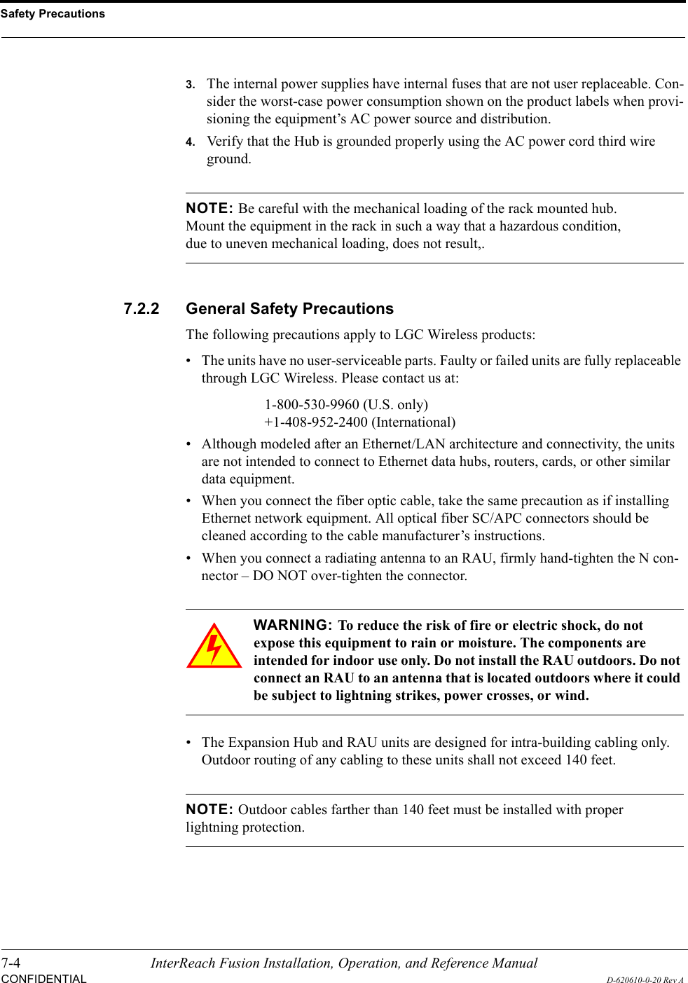
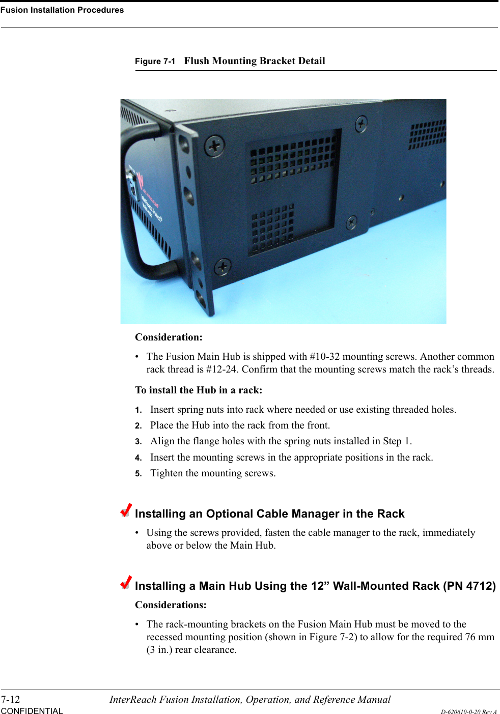
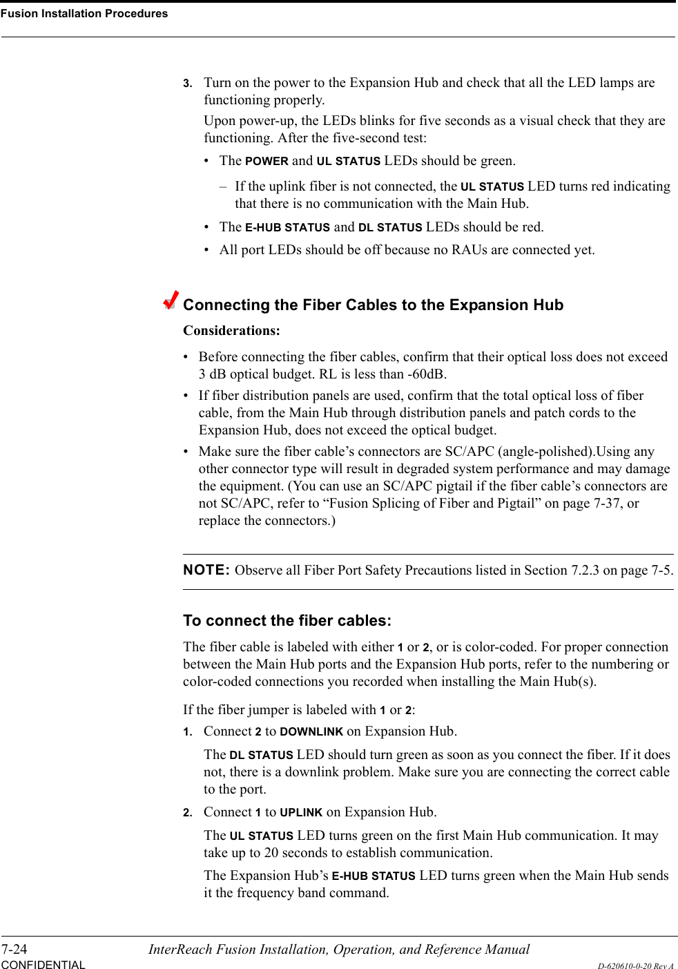
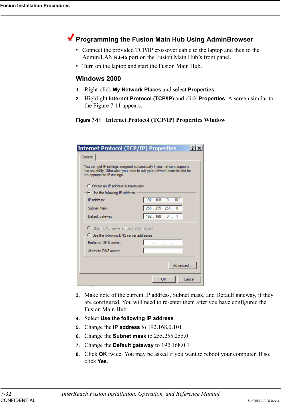
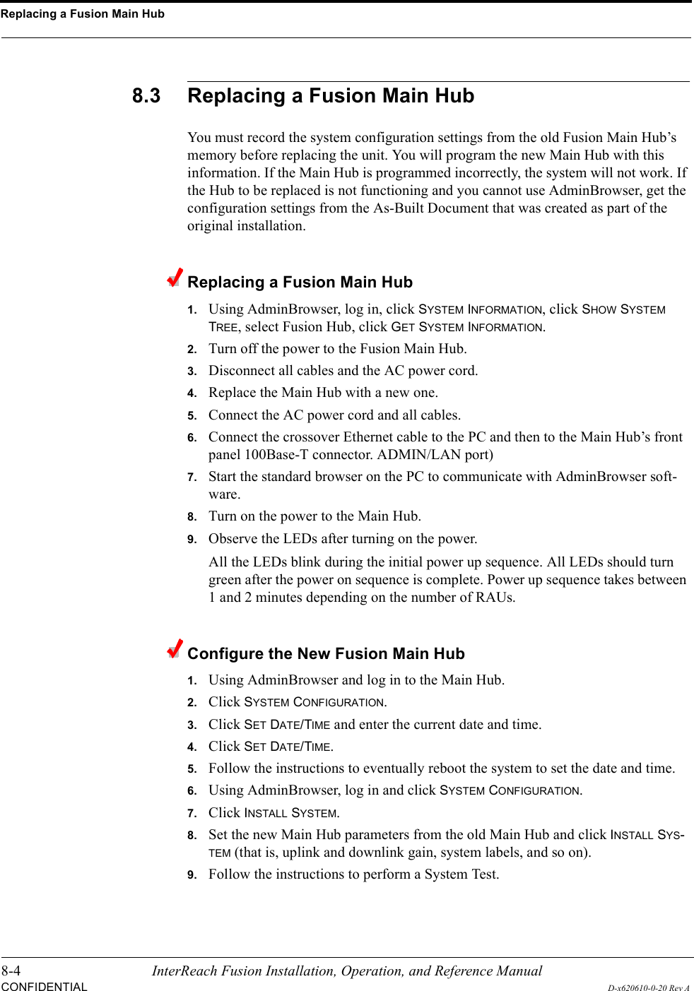
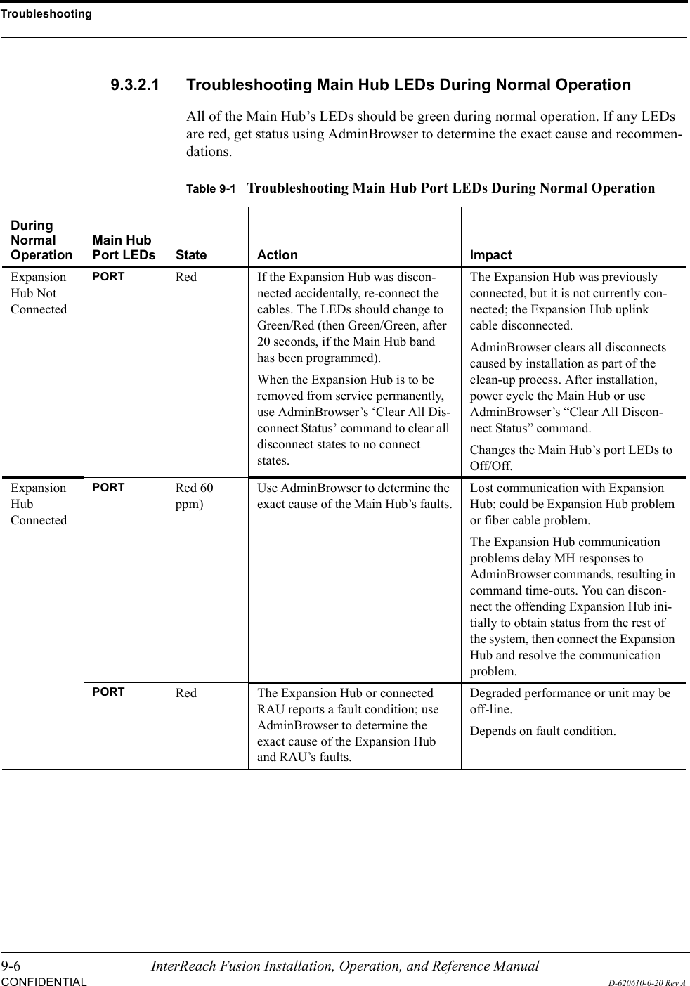
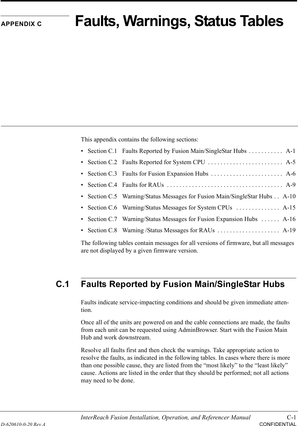
![Help Hot Line (U.S. only): 1-800-530-9960 C-19D-620610-0-20 Rev ACONFIDENTIALC.8 Warning /Status Messages for RAUsIn Table C-8, the message number is in the following form:[Rnn]/X where nn equals the message number, and X equals the default of either Sta-tus (S) or Warning (W).Table C-8Warning/Status Messages for RAUsMessage NumberDefault Description Reason/Action[R01]/W Temperature High. Check RAU location for excessive temperature; check for air flow blockage and/or incorrect installation. Move the RAU to a cooler environment.[R02]/W No communications from Hub. Check the cable for high RF loss. Switch the cable connec-tion to a different hub port. If the problem persists, replace the RAU.[R03]/W DL RF path loss is too high. Check the cable for high RF loss. Switch the cable connec-tion to a different hub port. If the problem persists, replace the RAU.[R04]/W DL RF path exceeds maximum gain.Check the Hub for proper operation; switch the cable con-nection to a different hub port. If the problem persists, replace the RAU.[R05]/S DL RF path problem (Band 1). Unable to complete the DL system end-to-end test, replace the RAU when possible.[R06]/S DL RF path problem (Band 2). Unable to complete the DL system end-to-end test, replace the RAU when possible.[R07]/S DL RF path problem (Band 3). Unable to complete the DL system end-to-end test, replace the RAU when possible.[R08]/S System test required. Run system test.[R09]/W Antenna Disconnected. Check RAU antenna connection; re-run system test.[R10]/S UL RF path problem (Band 1). Unable to complete the UL system end-to-end test, replace the RAU when possible.[R11]/S UL RF path problem (Band 2). Unable to complete the UL system end-to-end test, replace the RAU when possible.[R12]/S UL RF path problem (Band 3). Unable to complete the UL system end-to-end test, replace the RAU when possible.[R13]/S Problem detected in the RAU. Contact LGC Wireless Support for more information.[R14]/S Problem detected in the RAU. Contact LGC Wireless Support for more information.[R15]/S Problem detected in the RAU. Contact LGC Wireless Support for more information.[R16]/S Problem detected in the RAU. Contact LGC Wireless Support for more information.](https://usermanual.wiki/ADC-Telecommunications/FSN-809019-2.User-Manual-Part-Two/User-Guide-869356-Page-123.png)