ADC Telecommunications PRSM074C FlexWave™ Prism - 40 Watt 700 Upper C - Band User Manual 77073
ADC Telecommunications Inc FlexWave™ Prism - 40 Watt 700 Upper C - Band 77073
Contents
- 1. Prism Brochure
- 2. Manual part 1
- 3. Manual part 2
- 4. Manual part 3
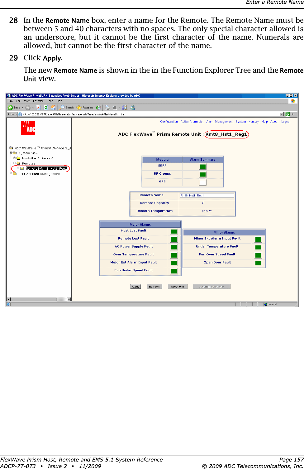
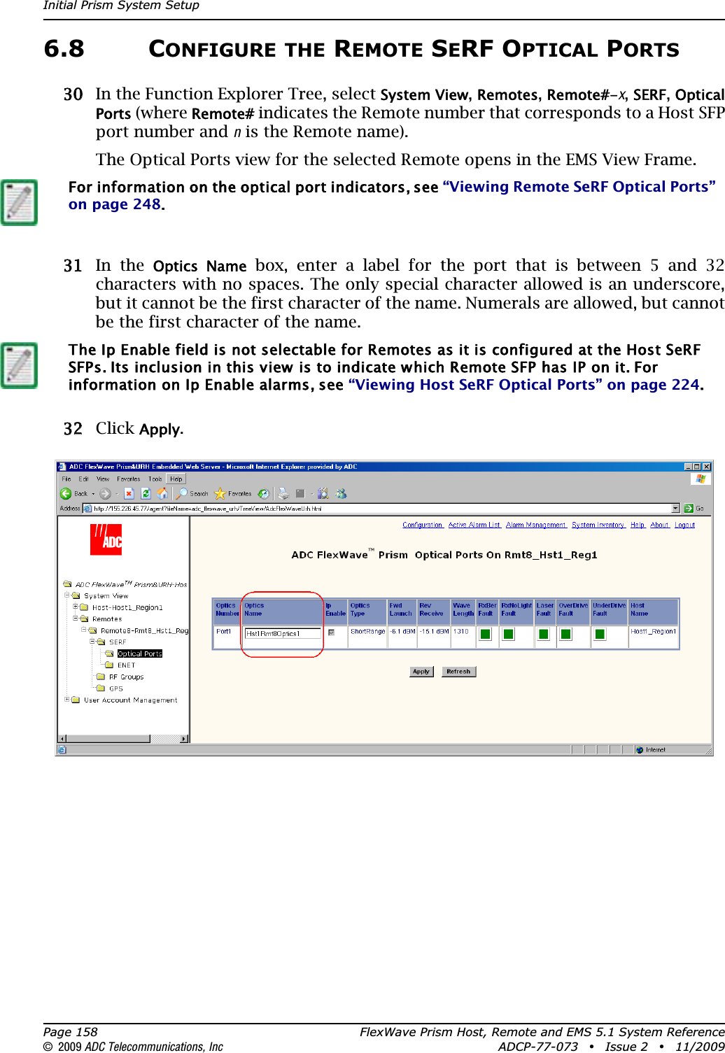
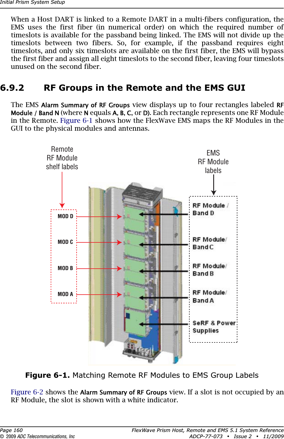
Manual part 2
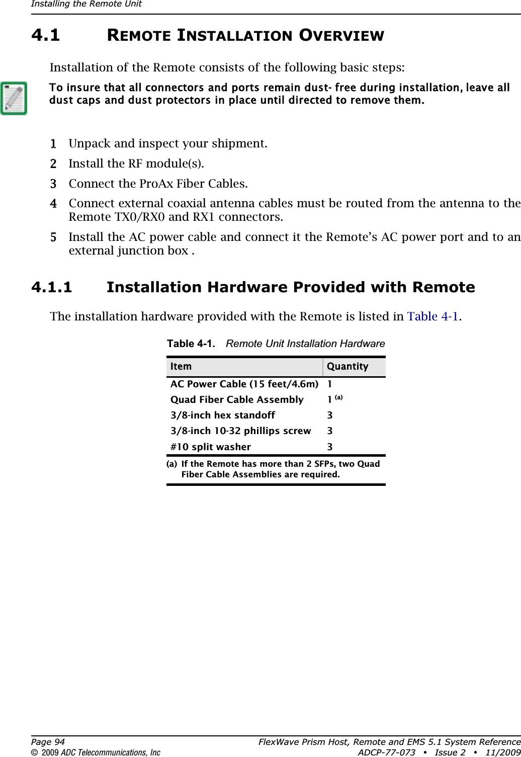
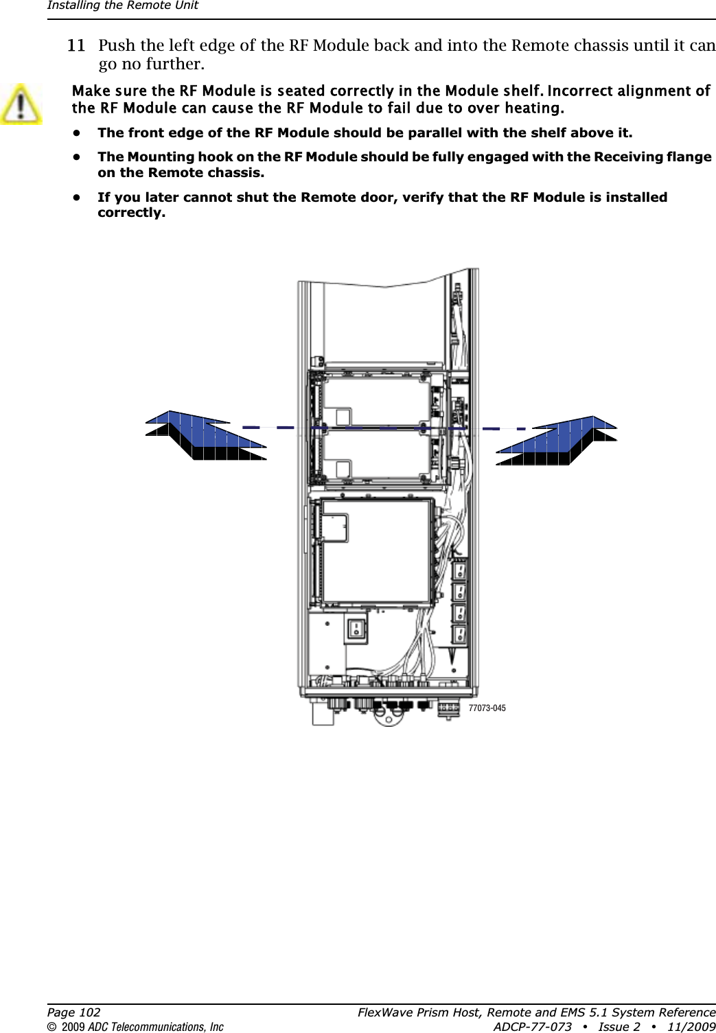
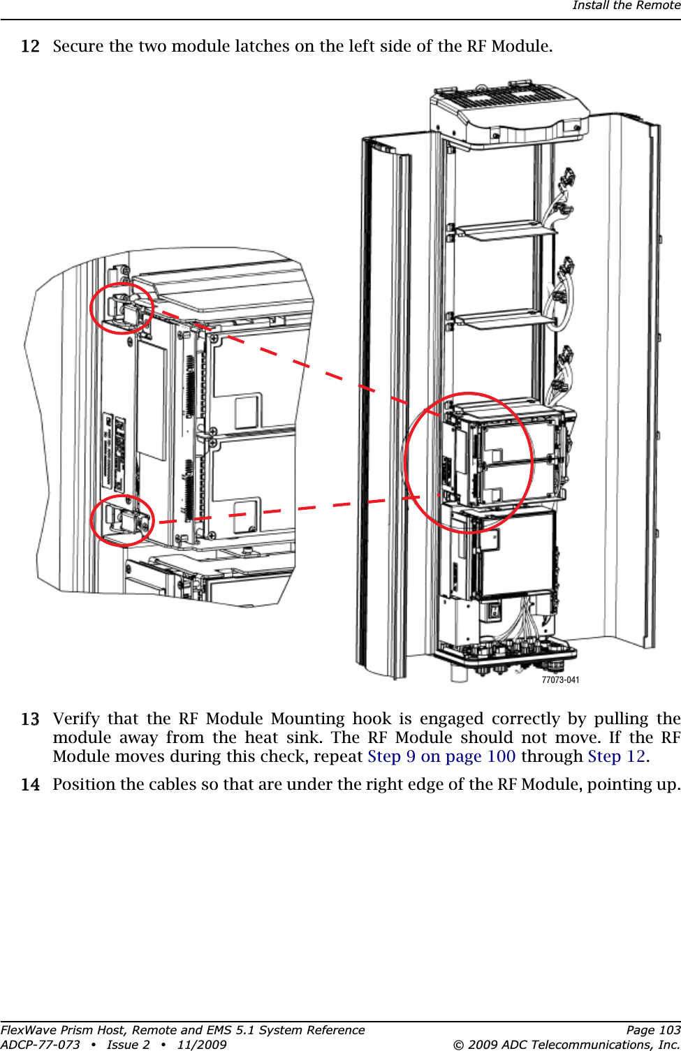
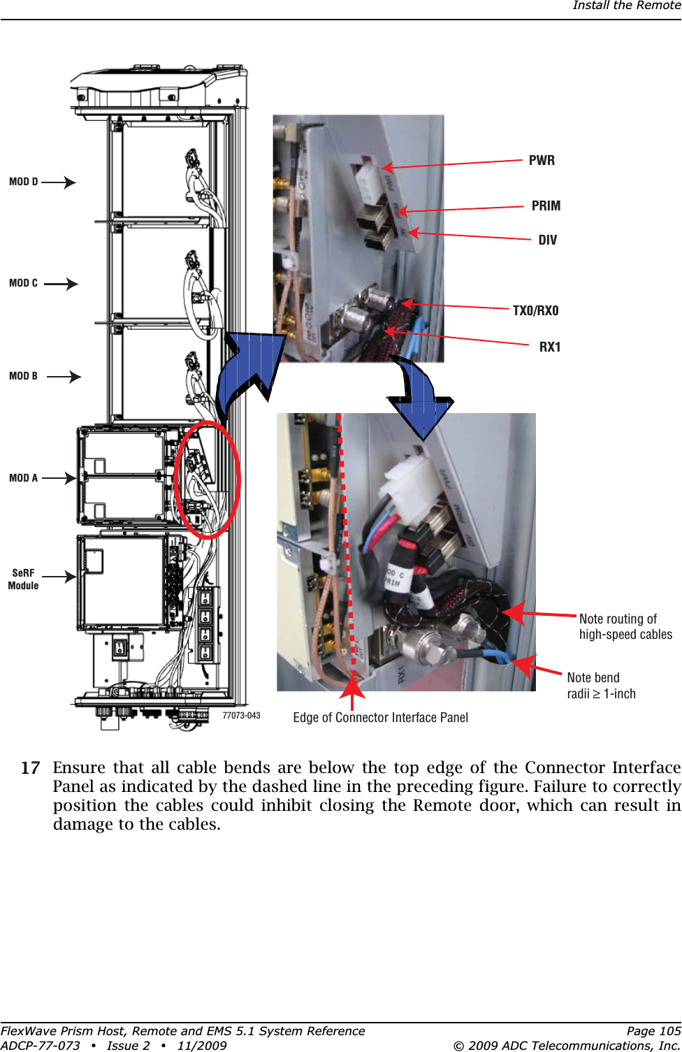
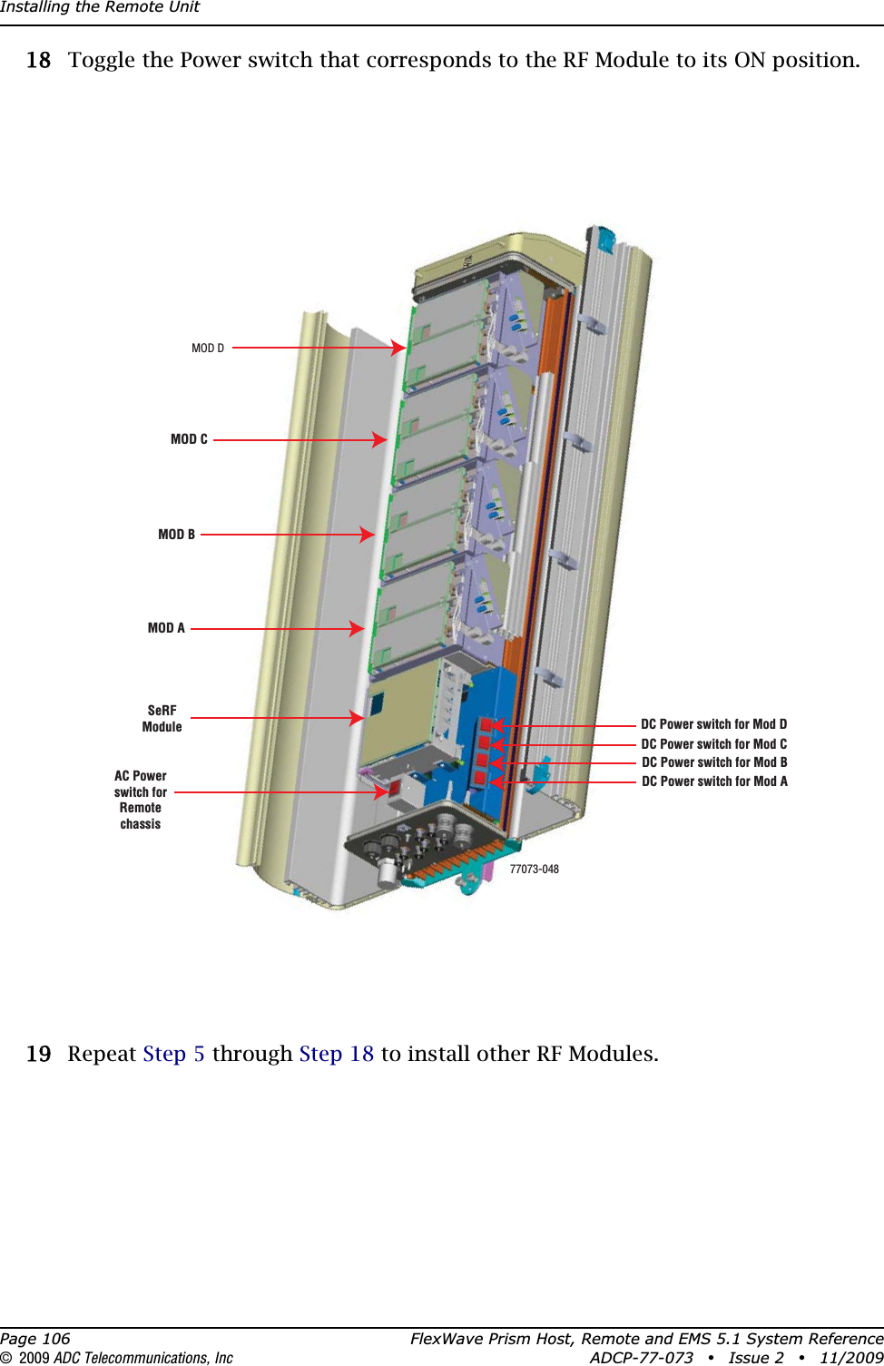
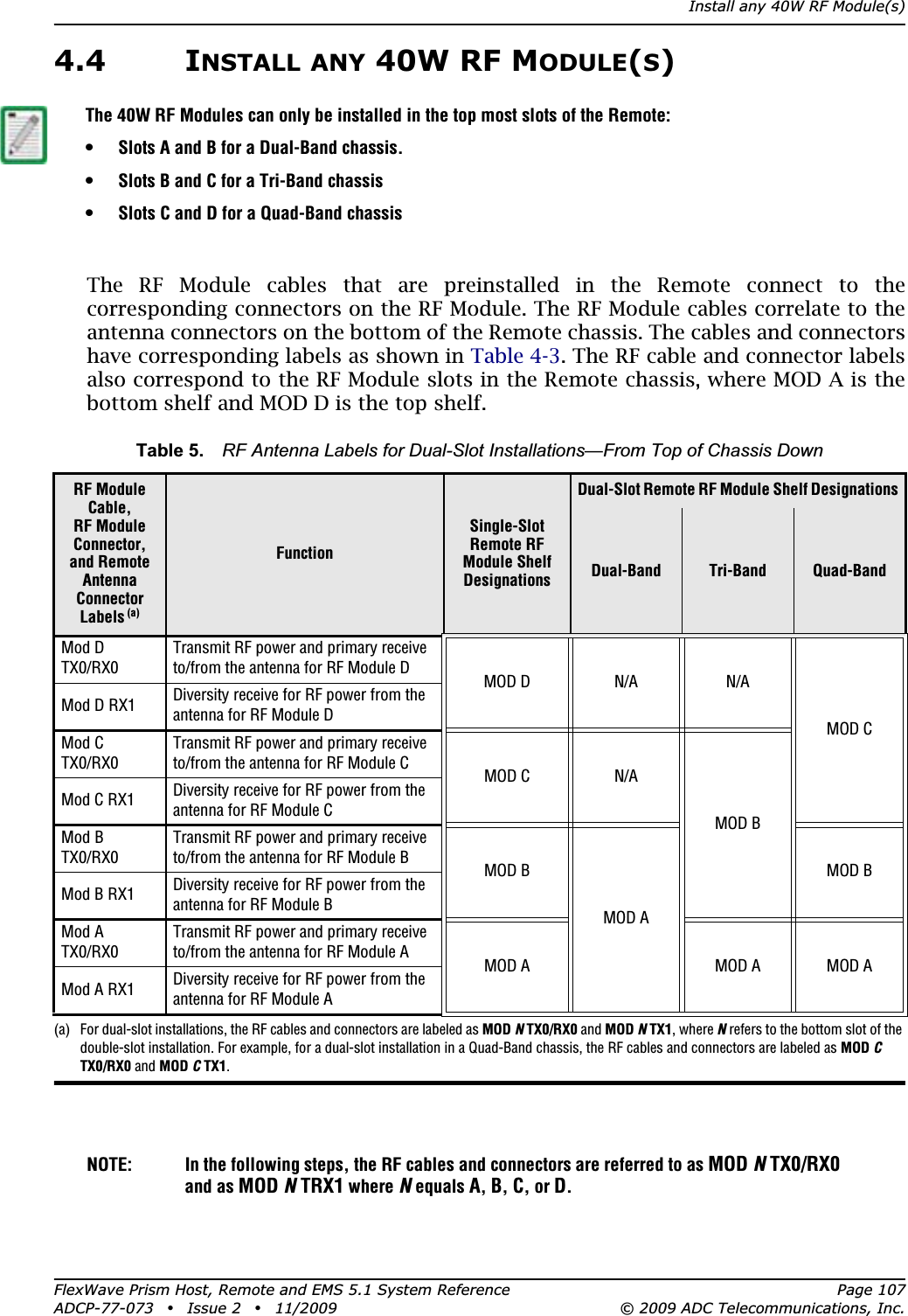
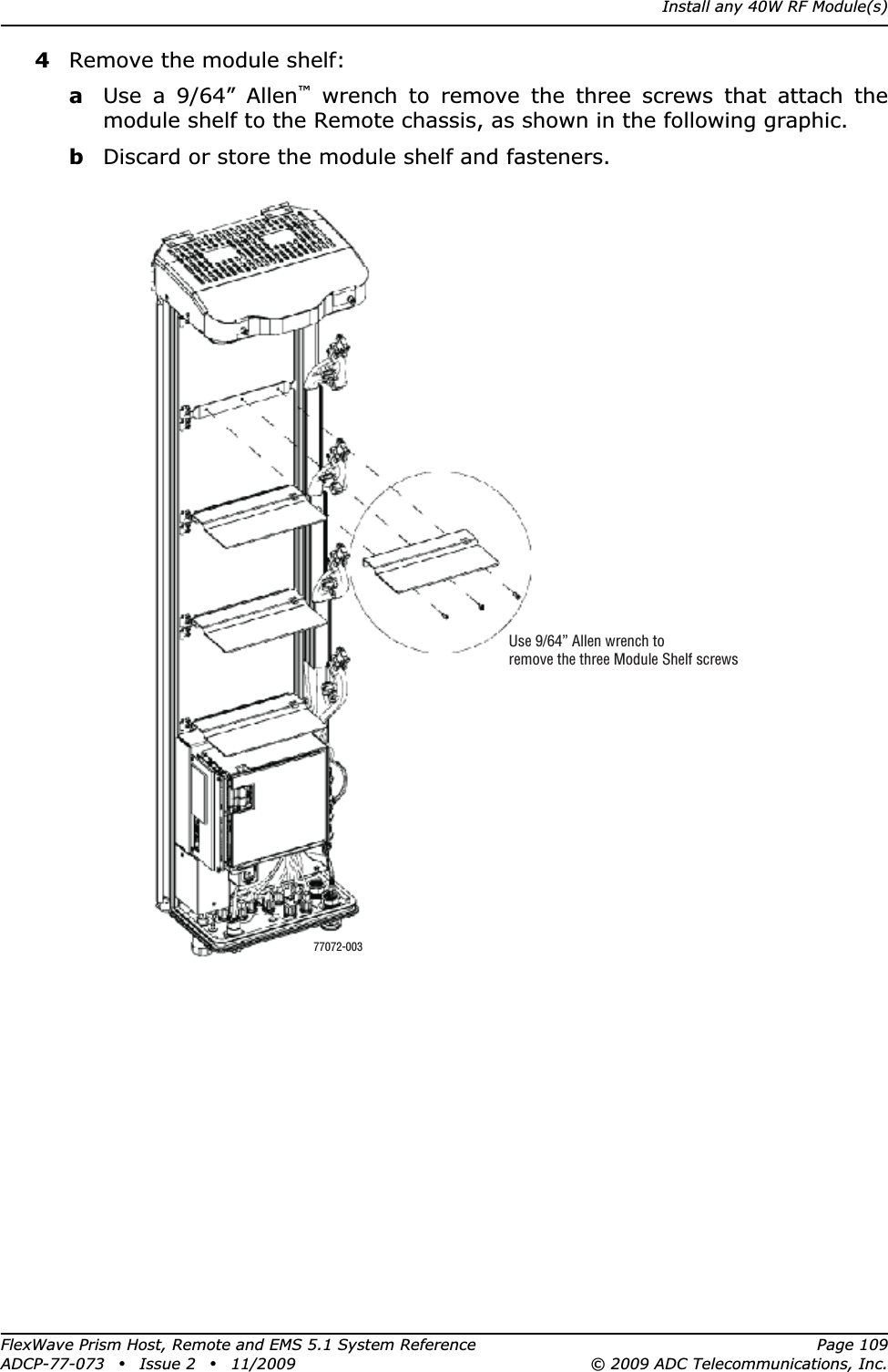
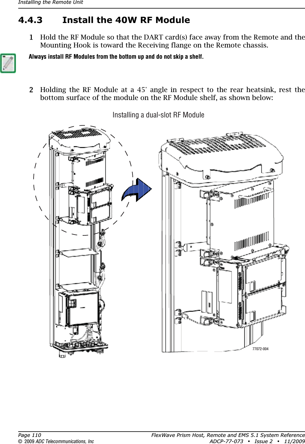
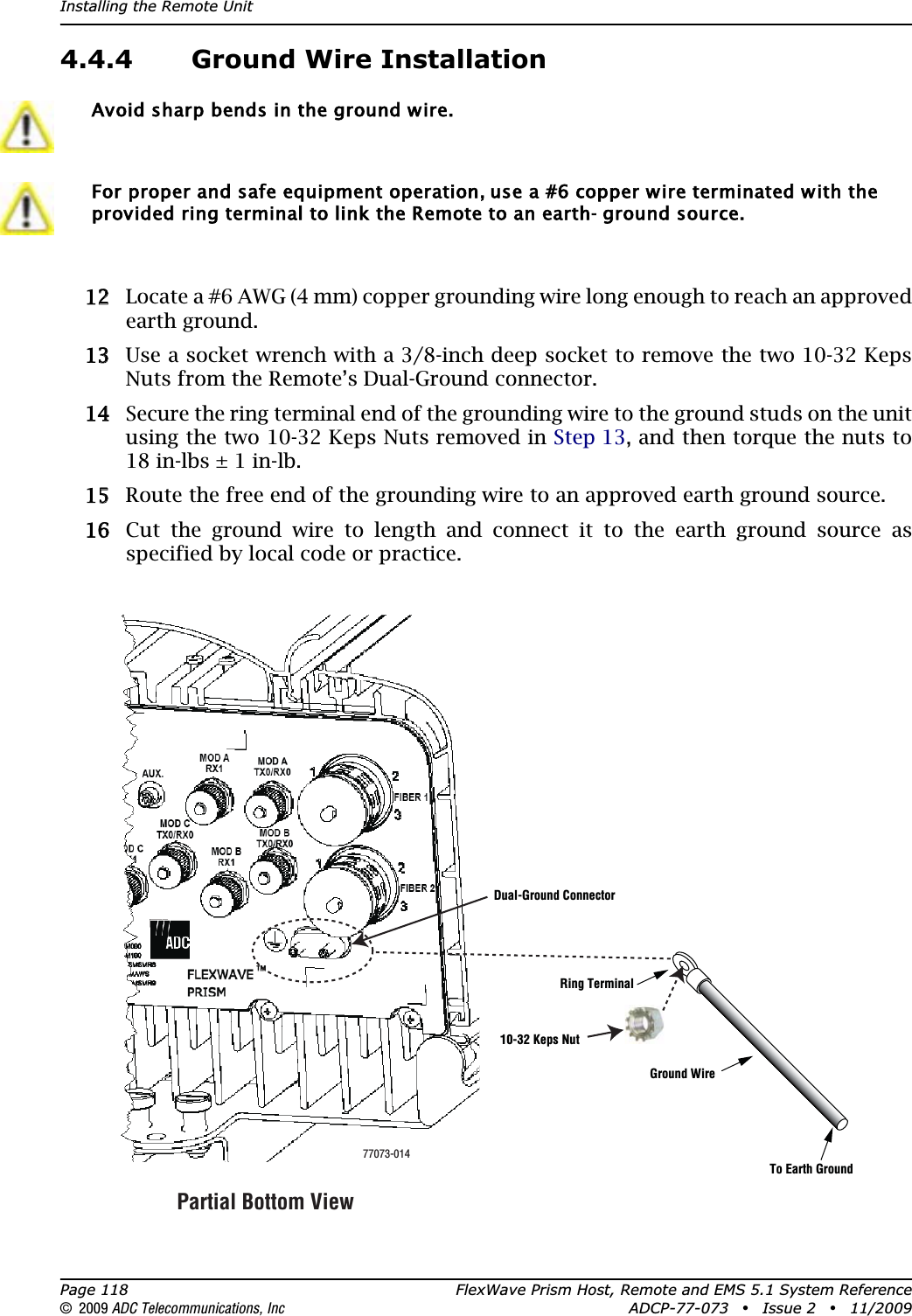
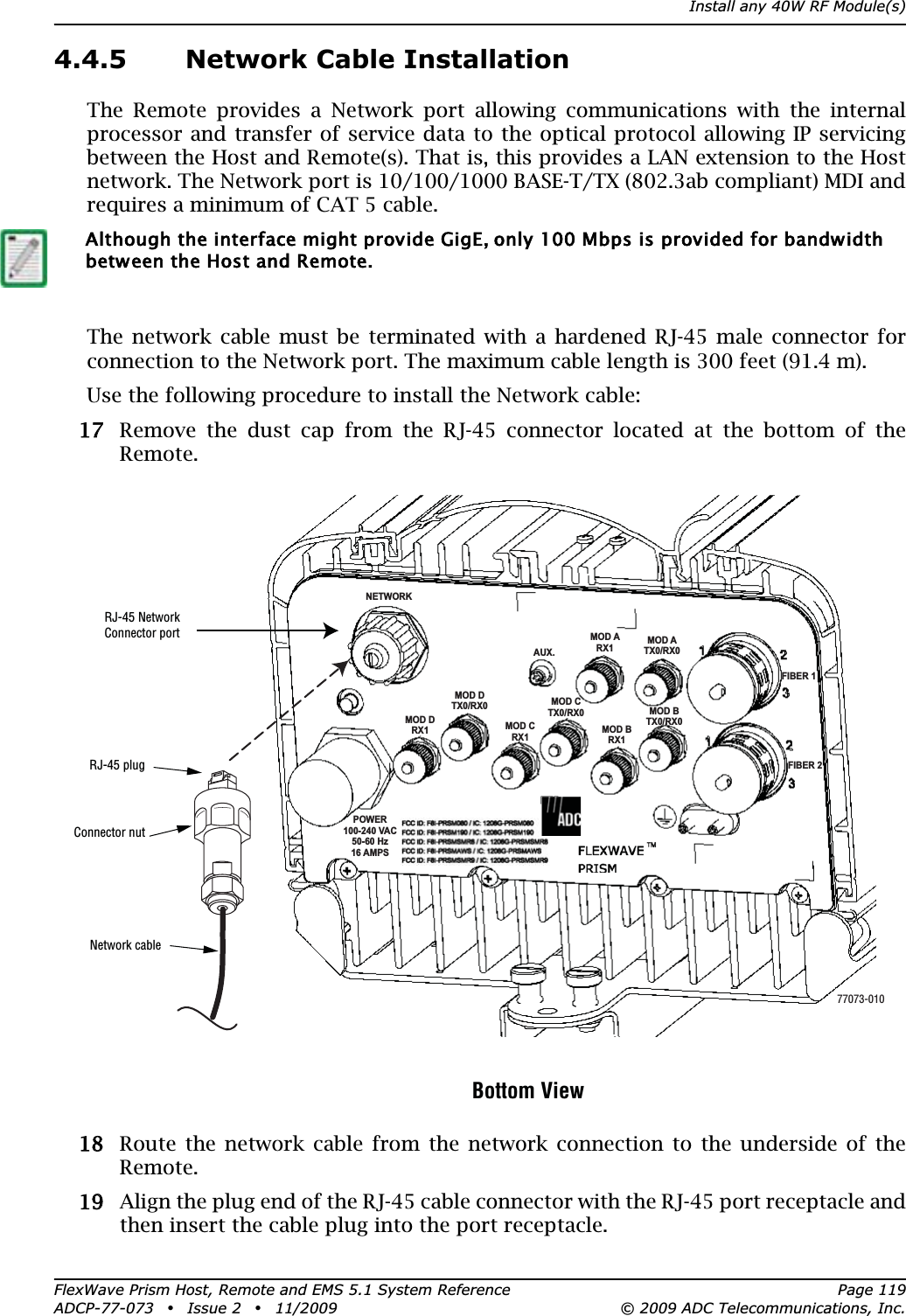
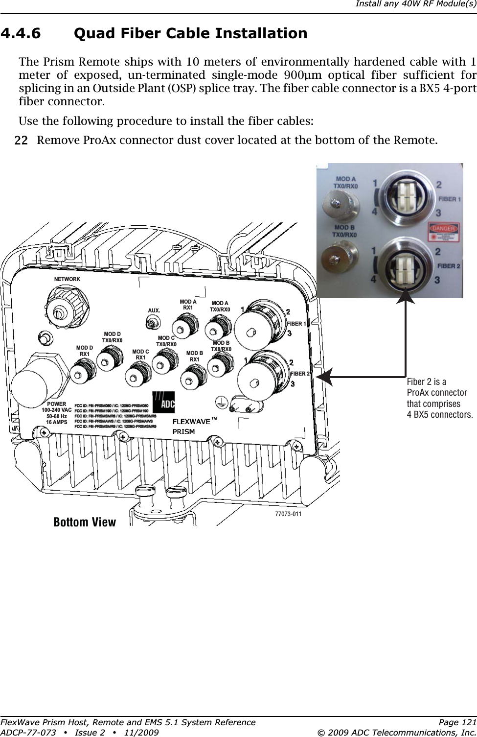
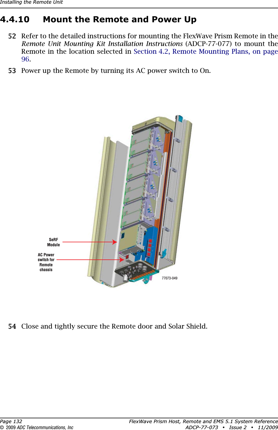
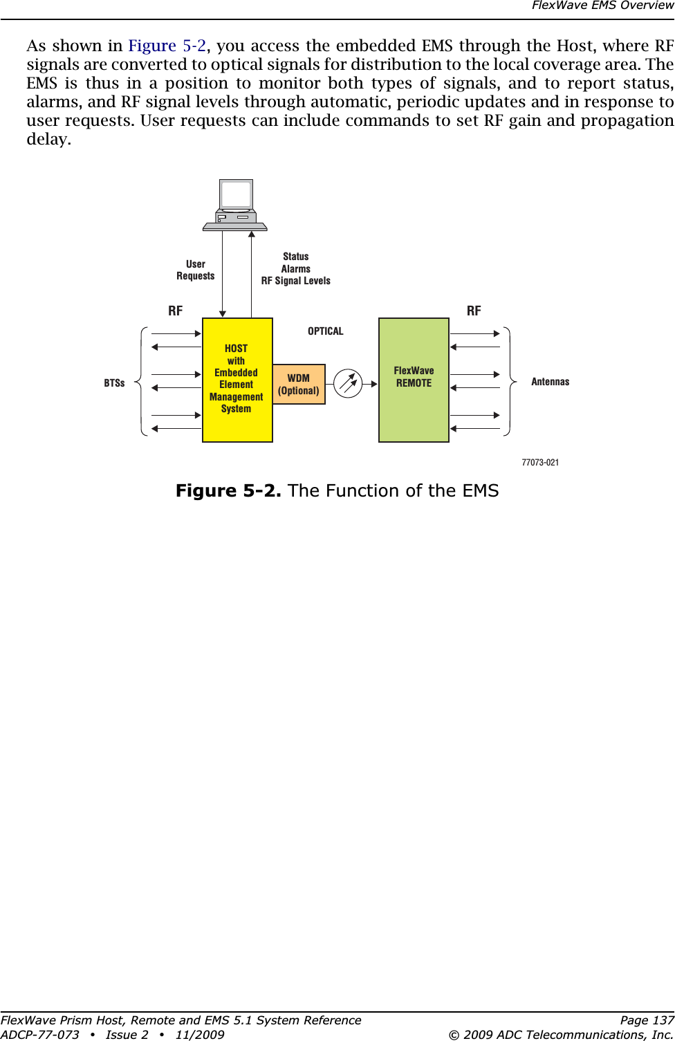
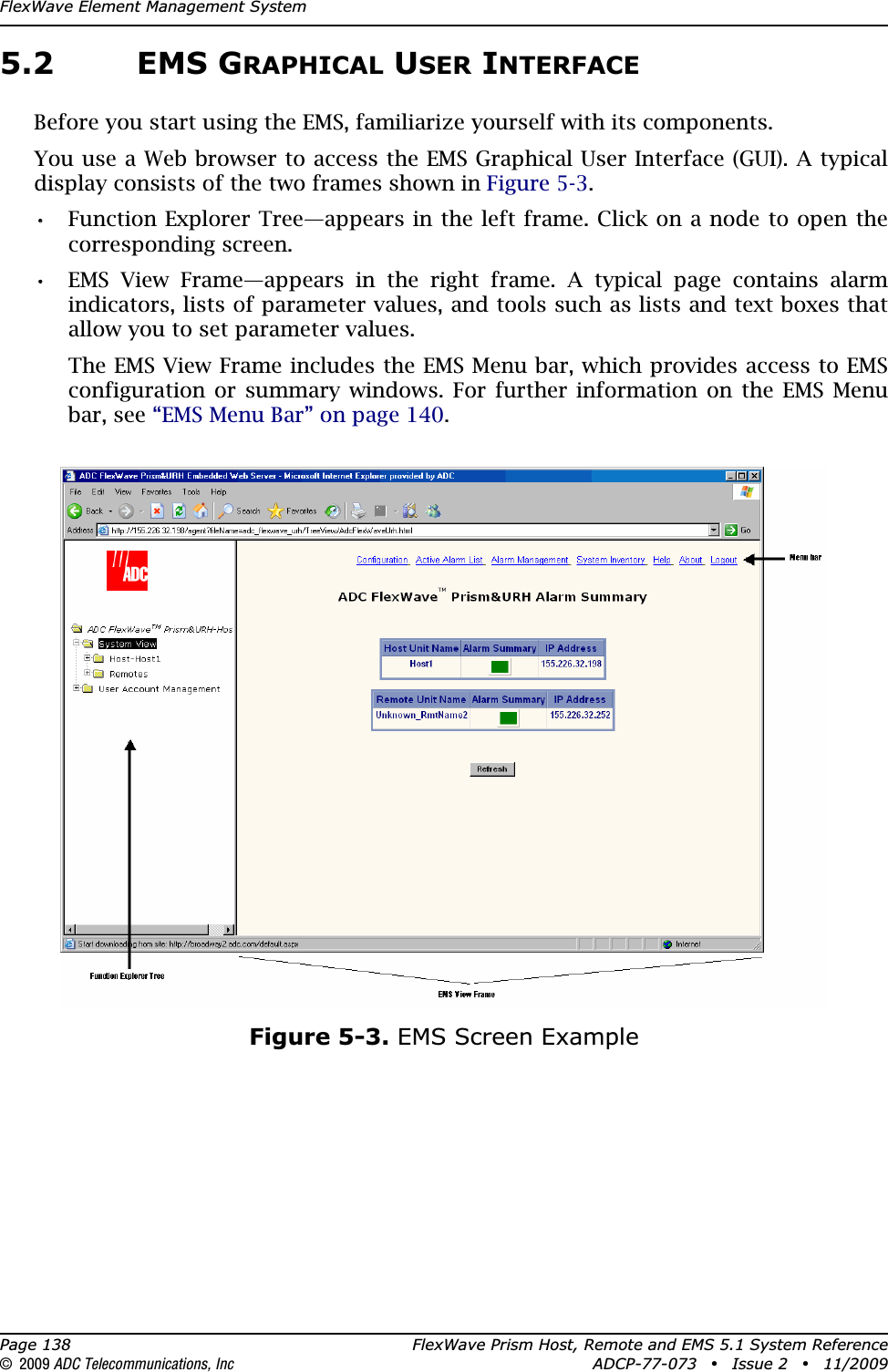
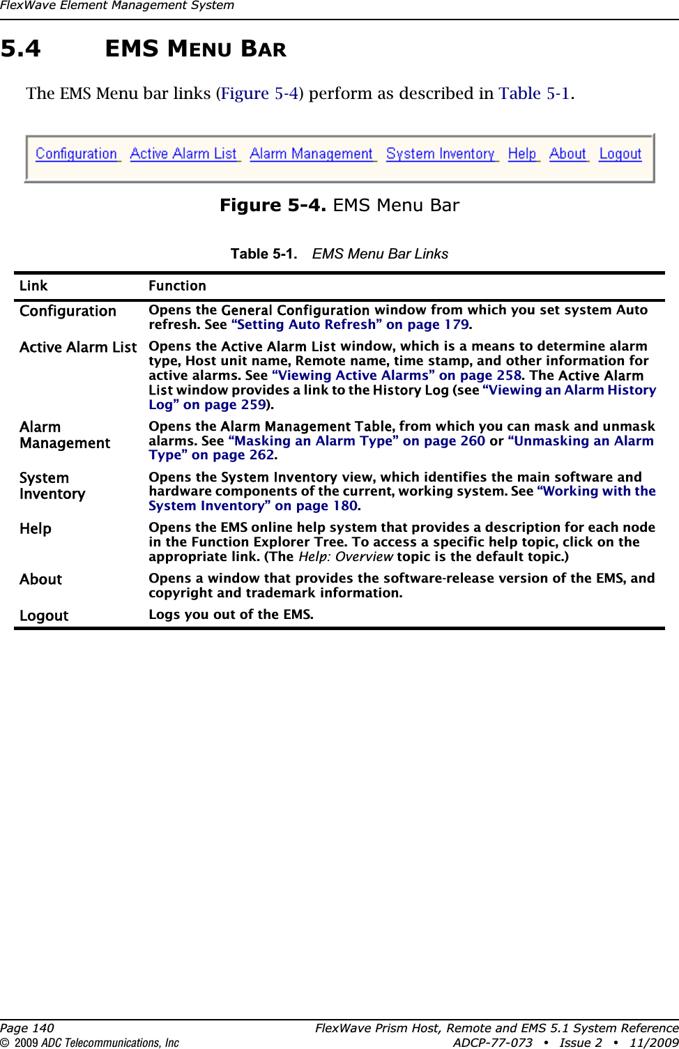
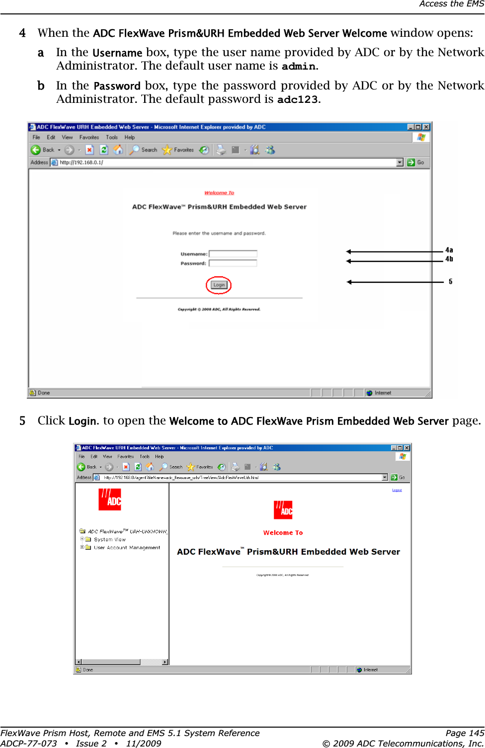
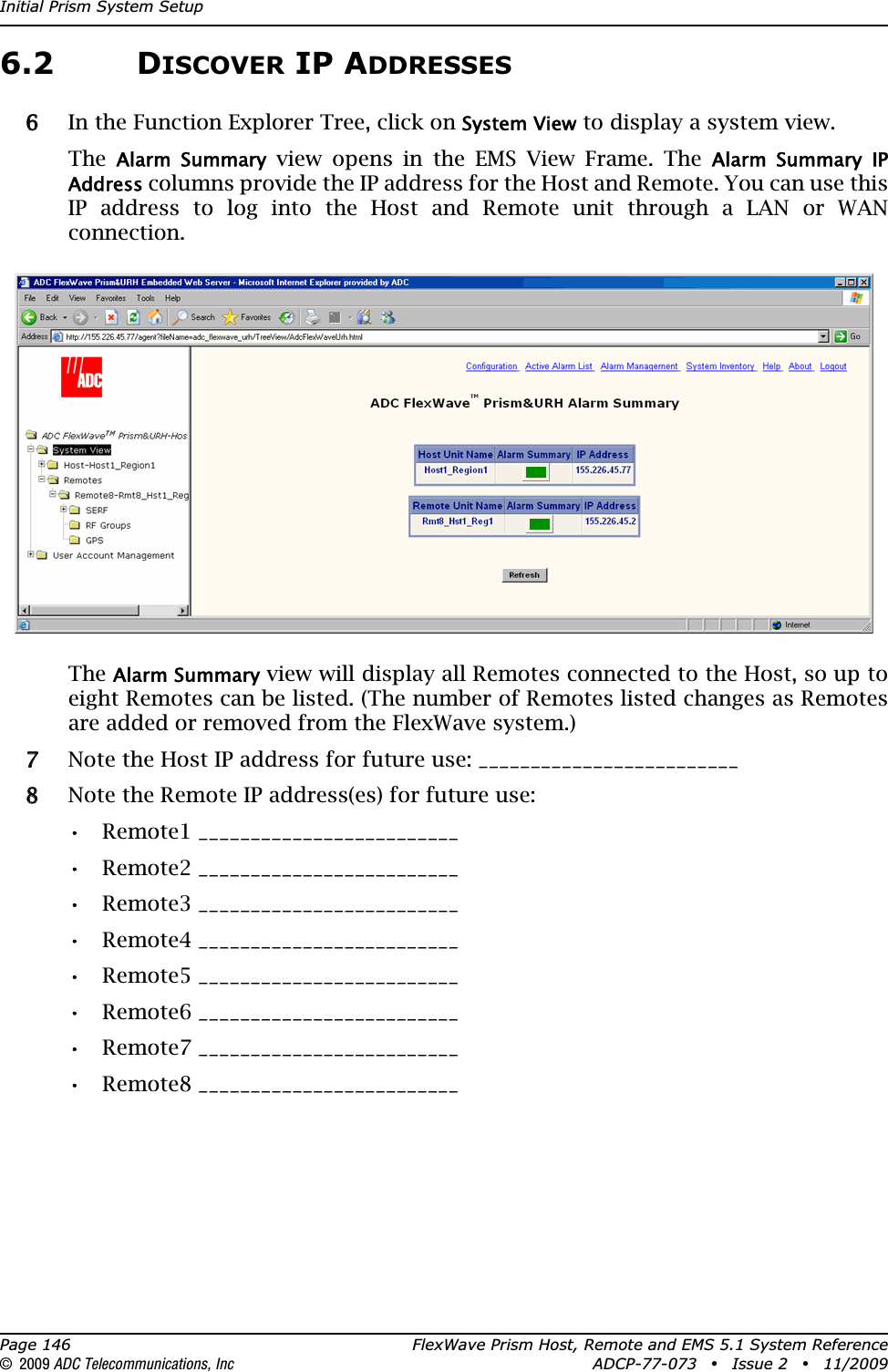
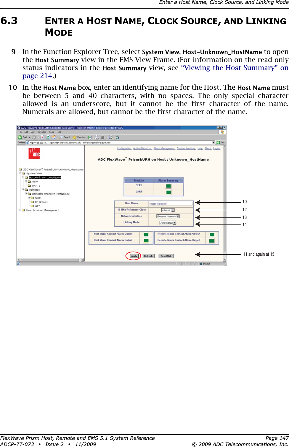
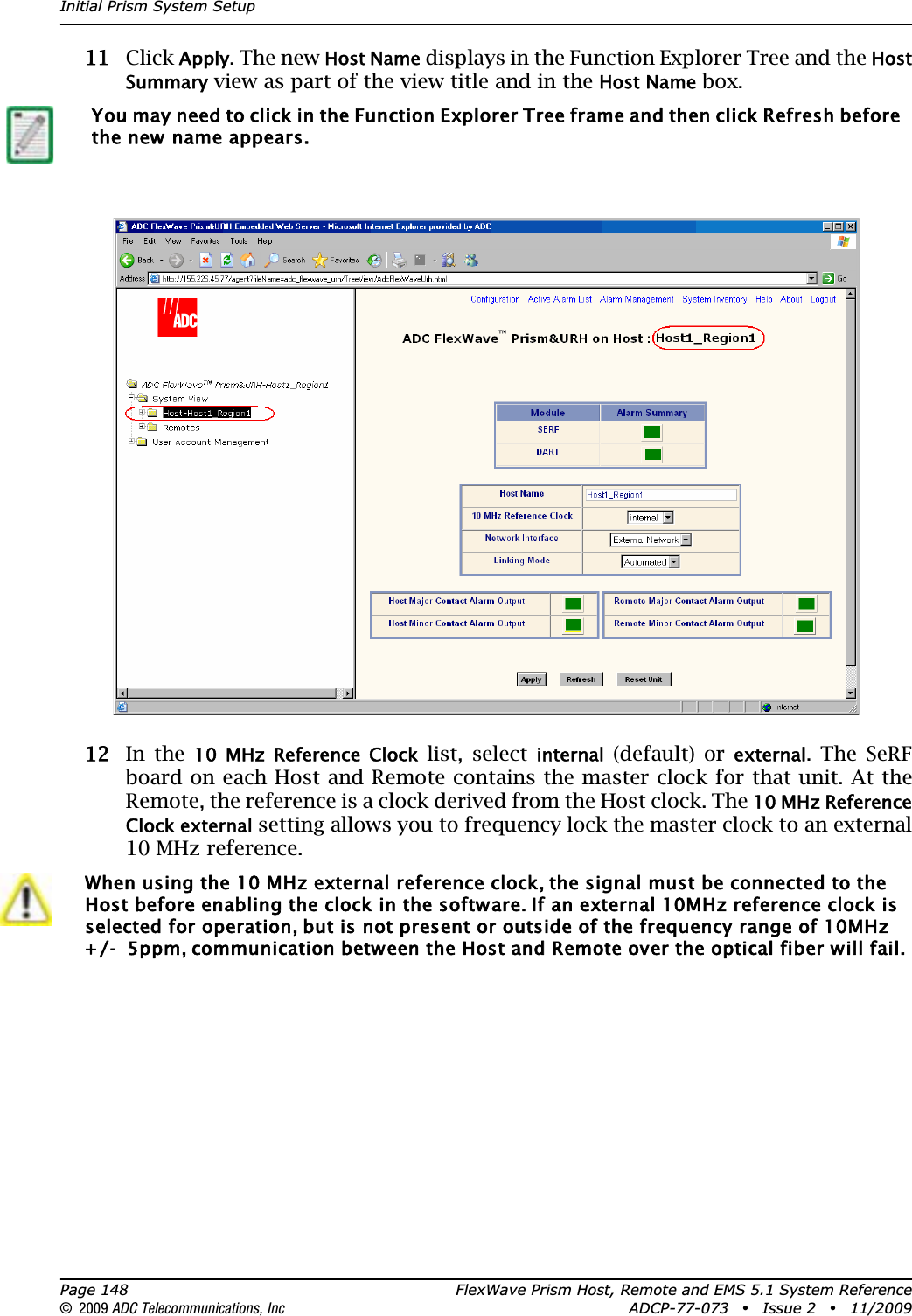
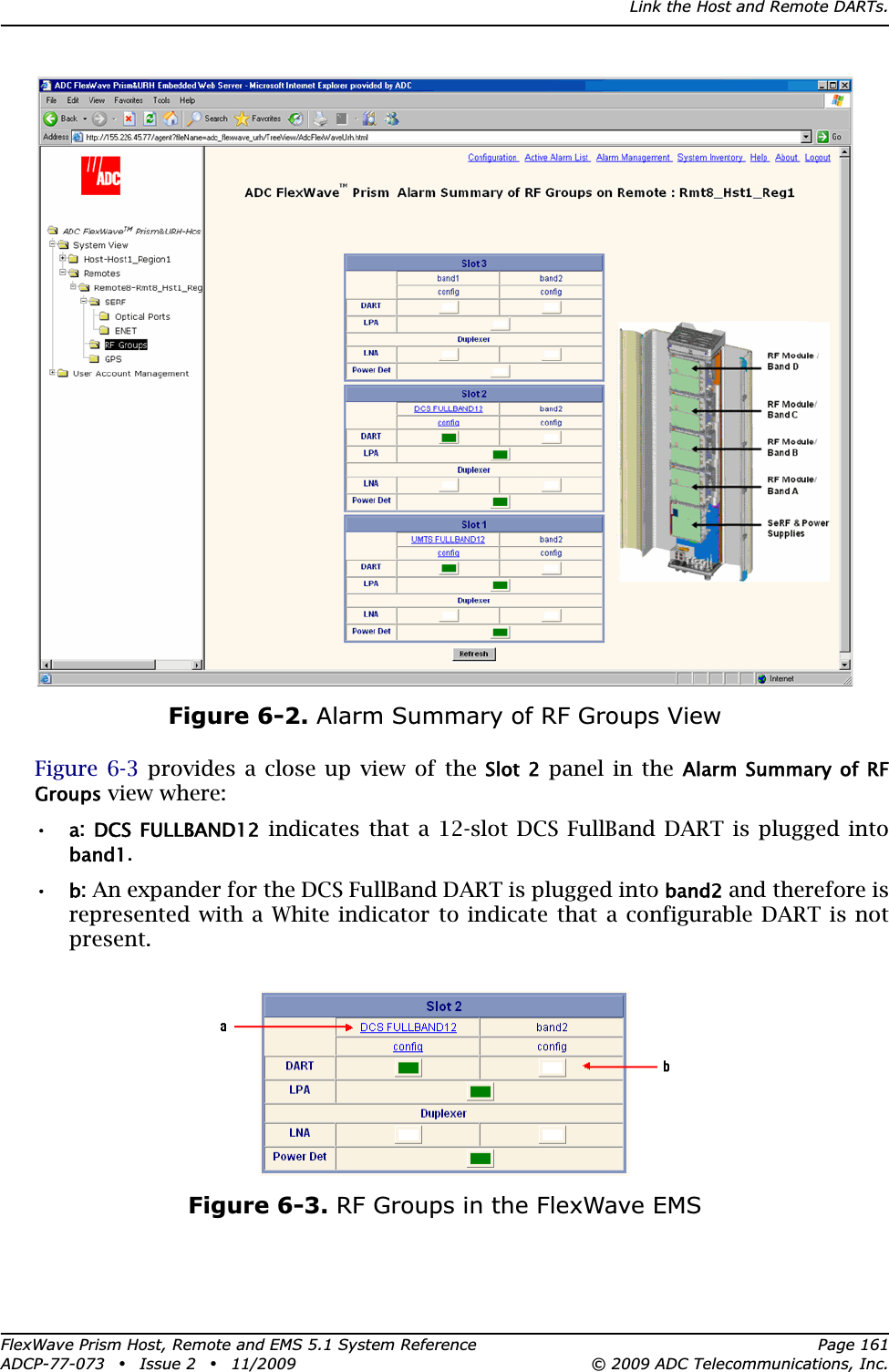
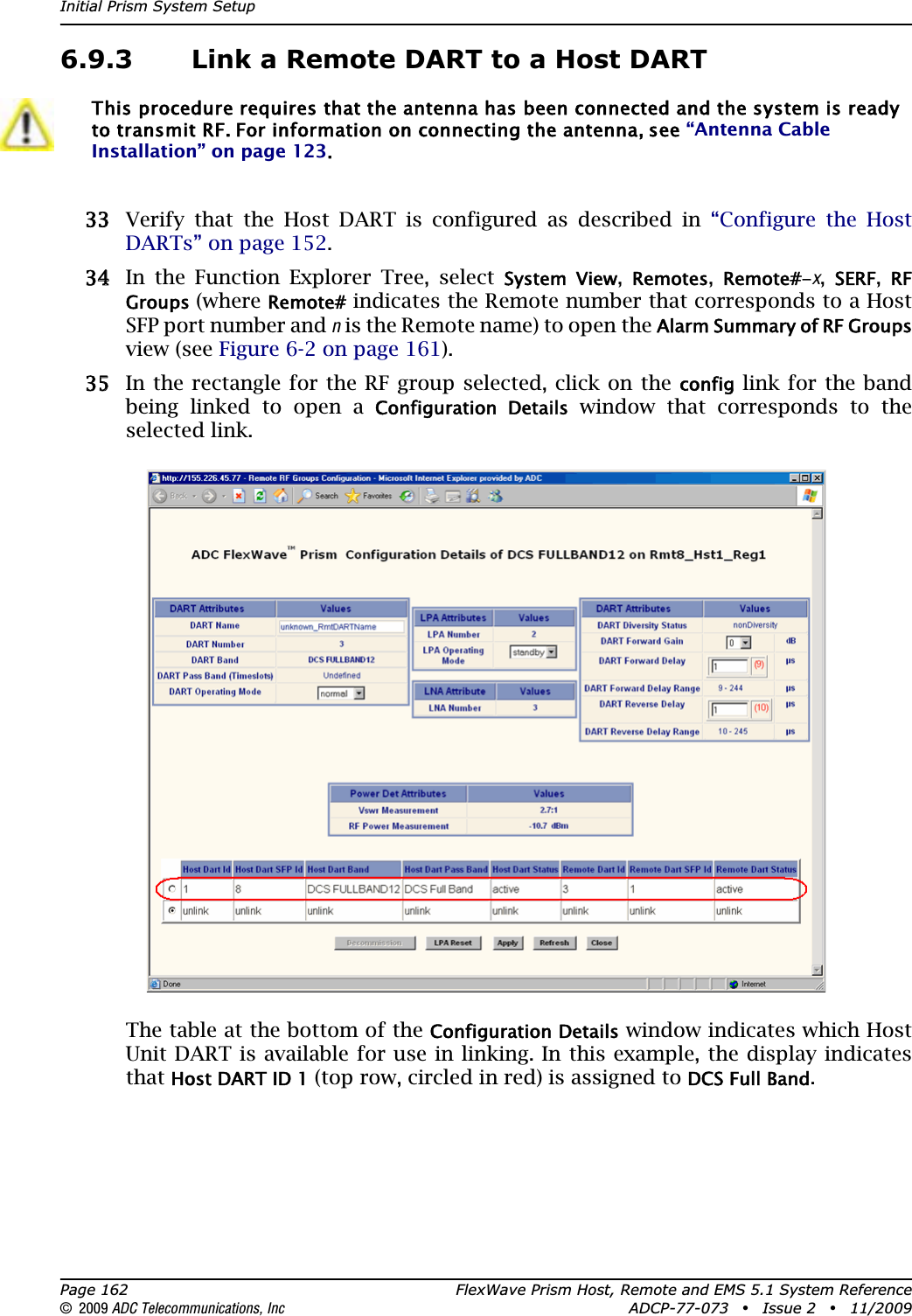
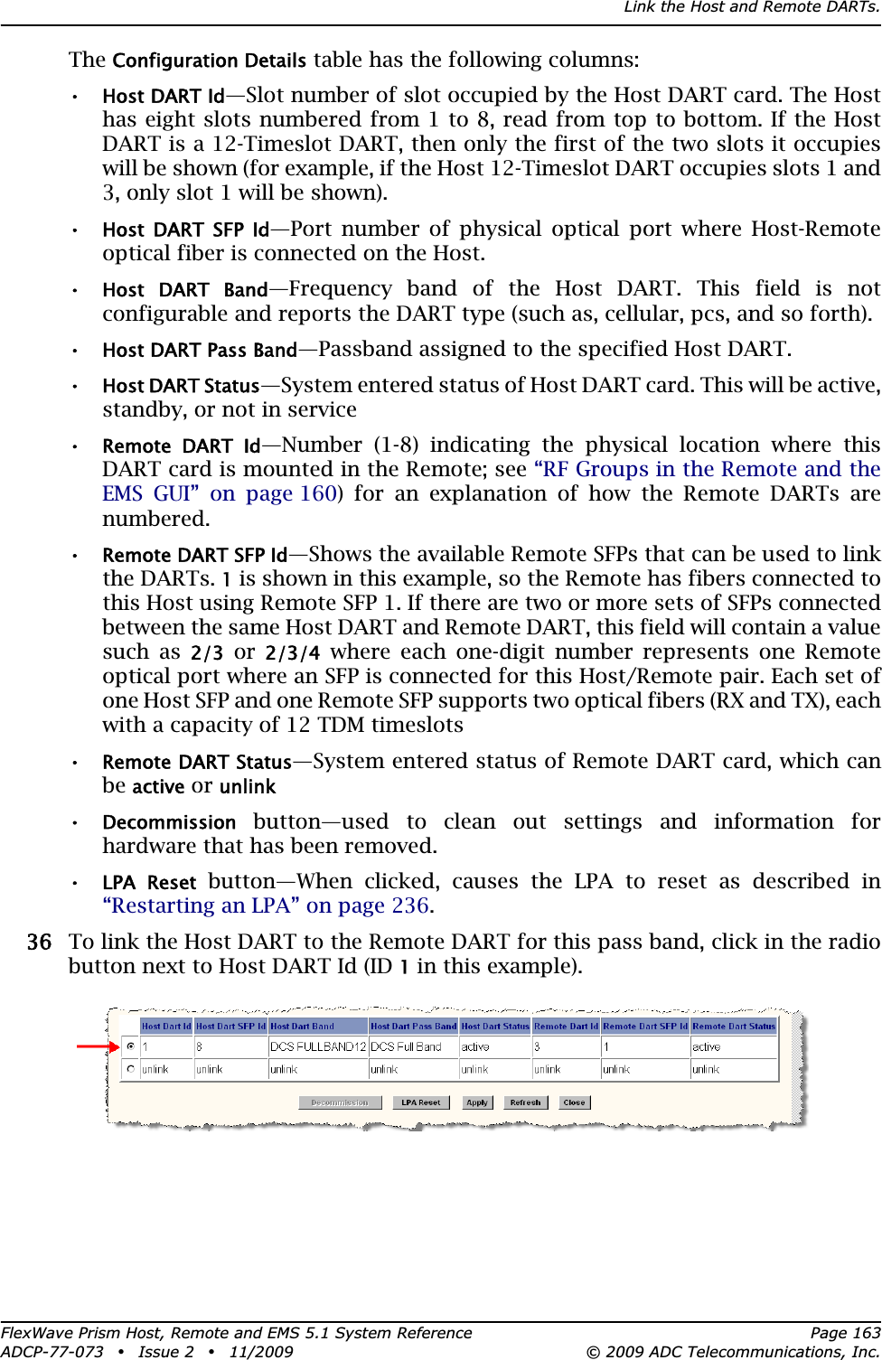
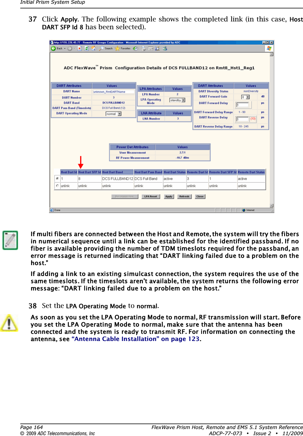
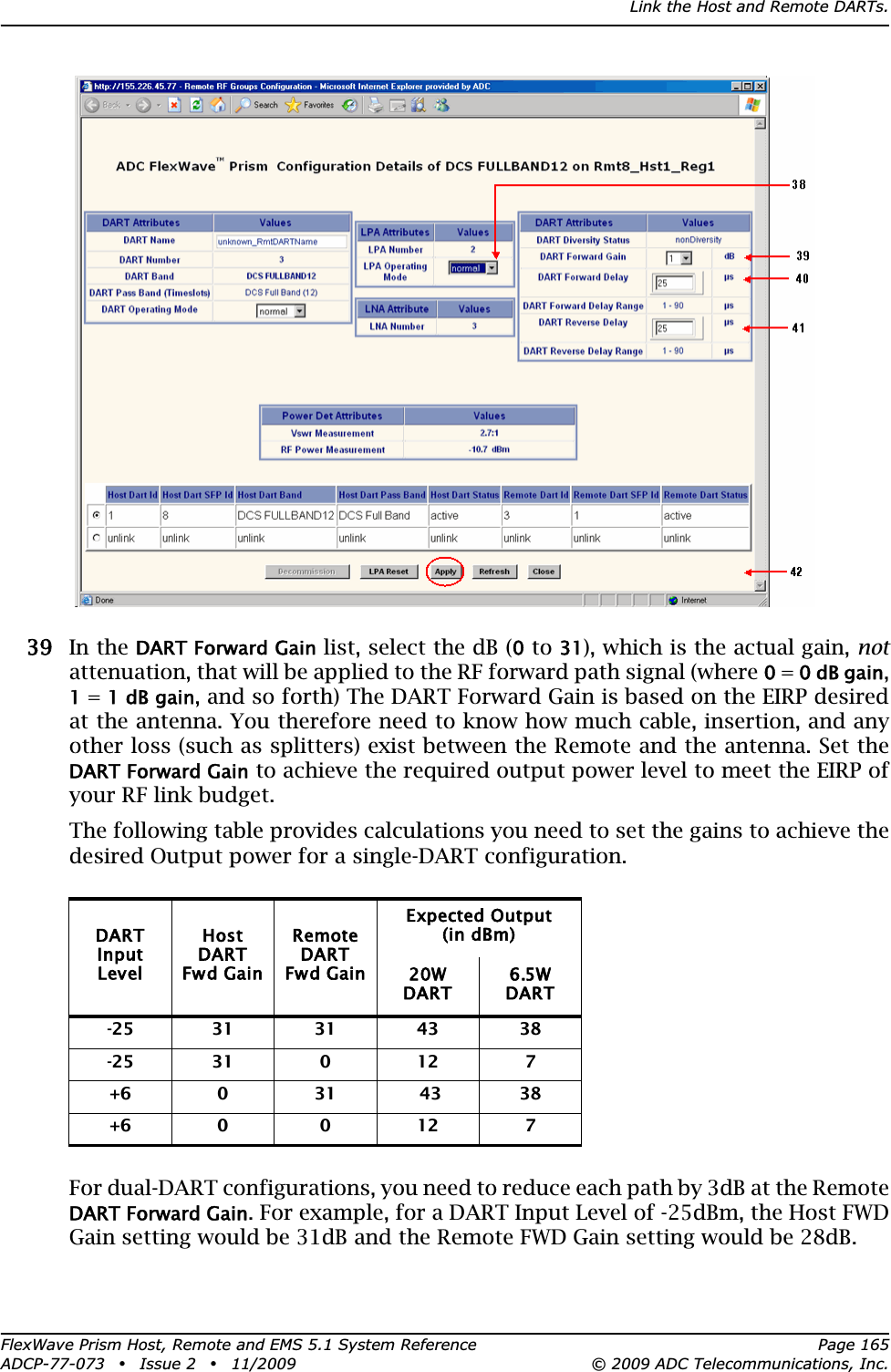
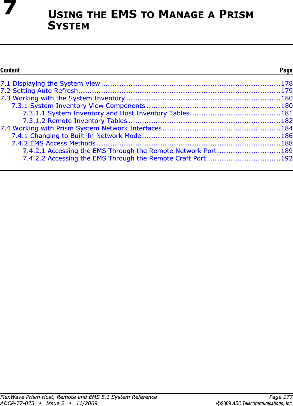
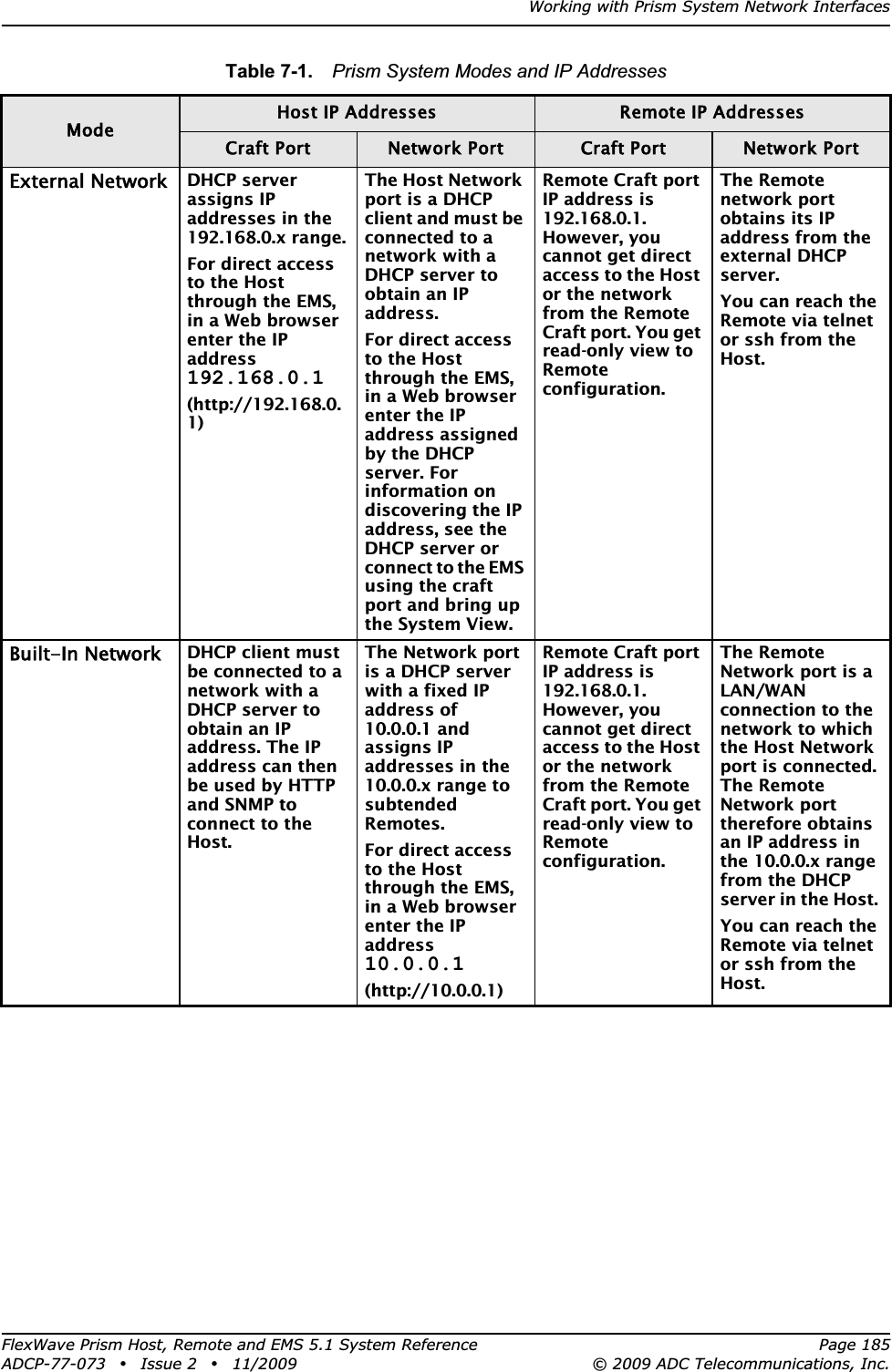
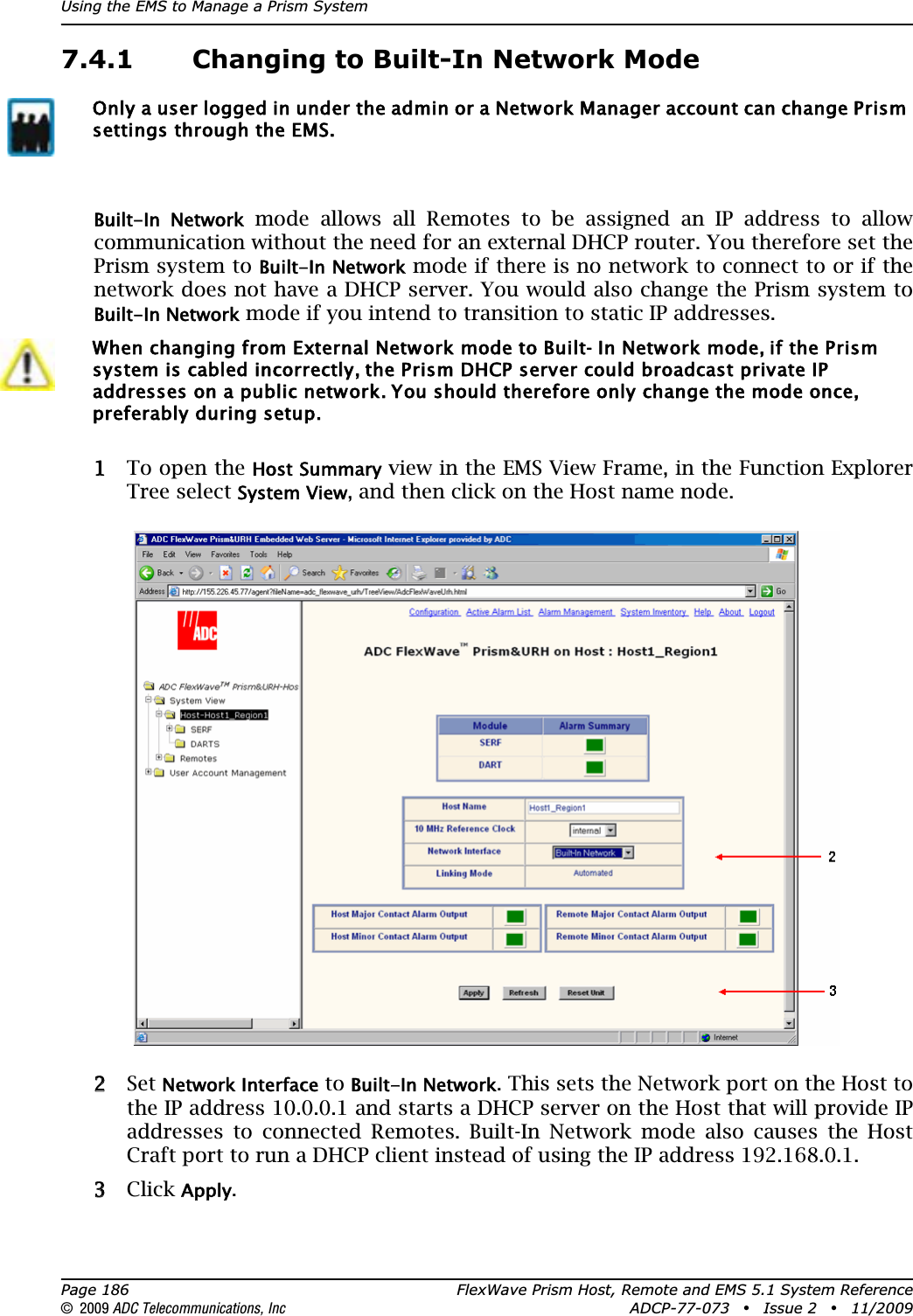
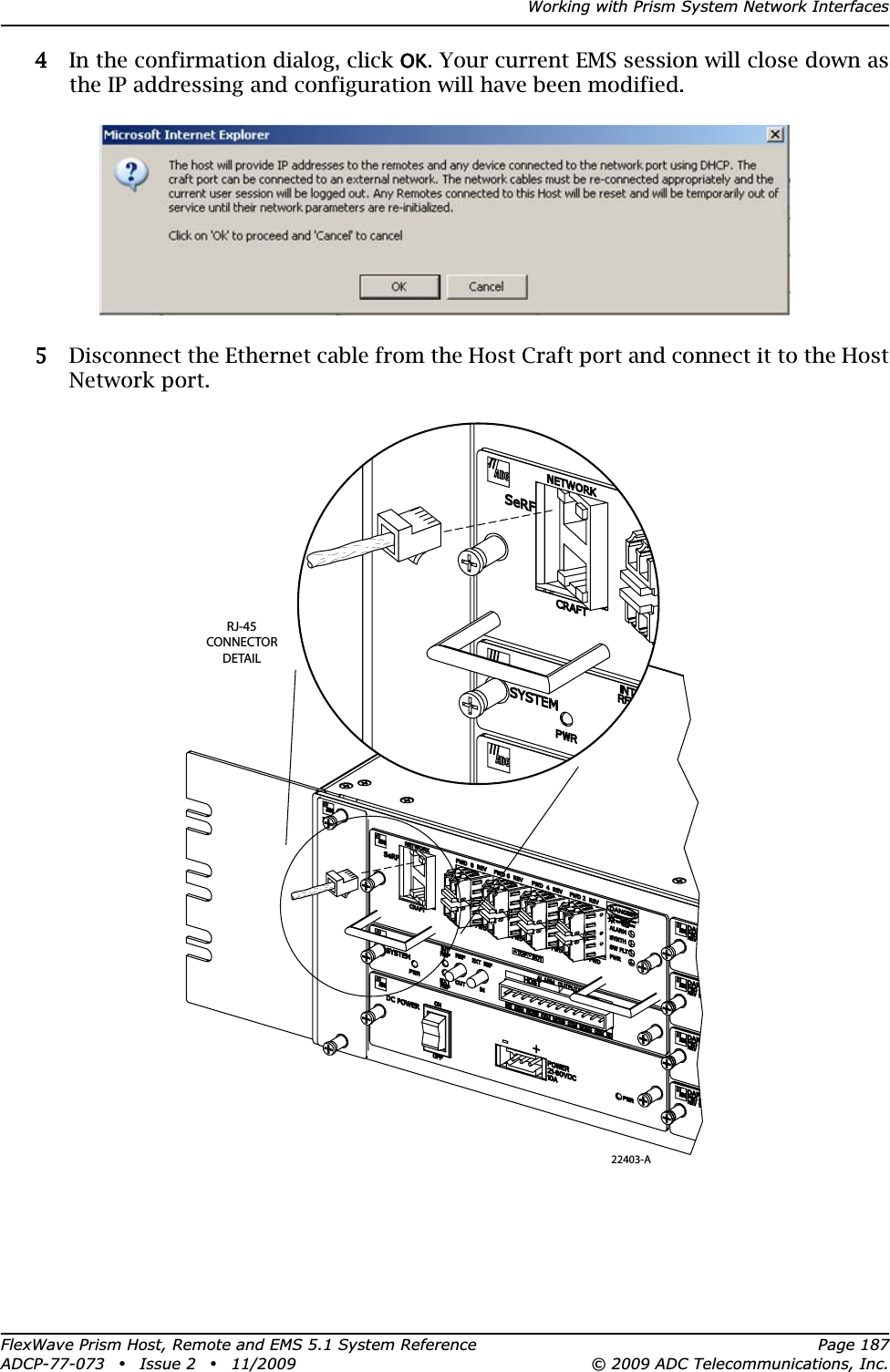
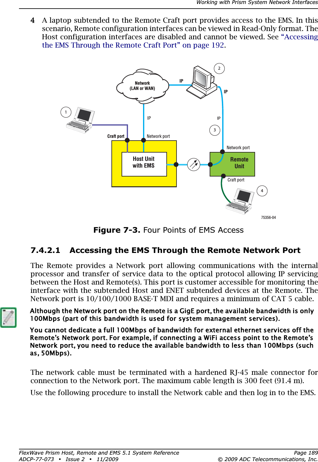
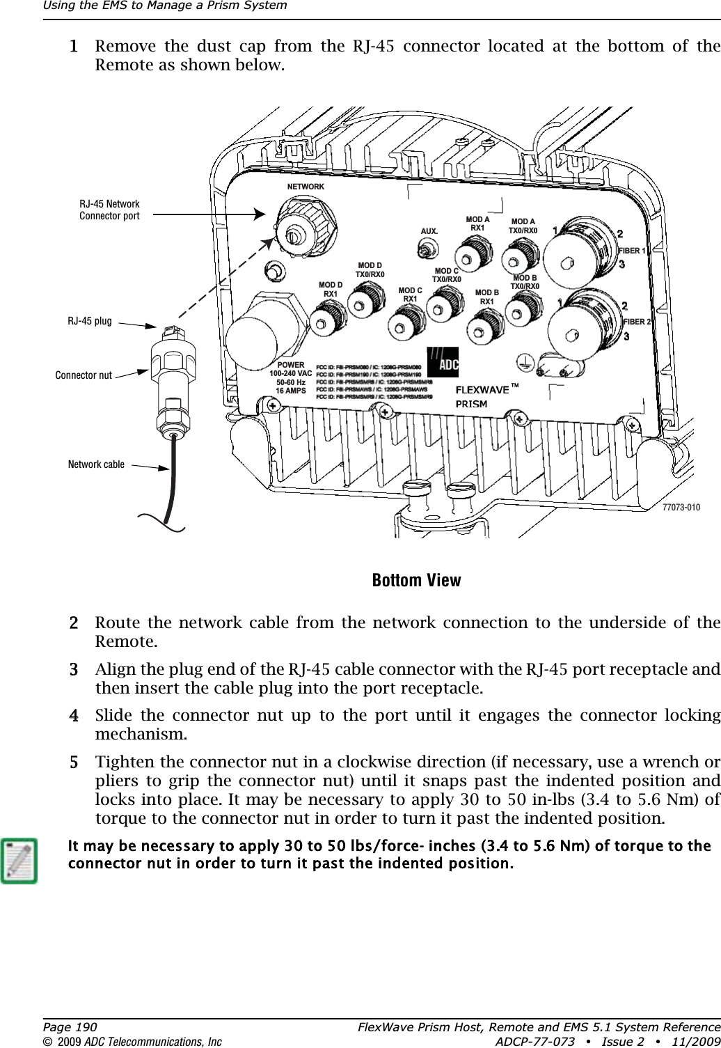
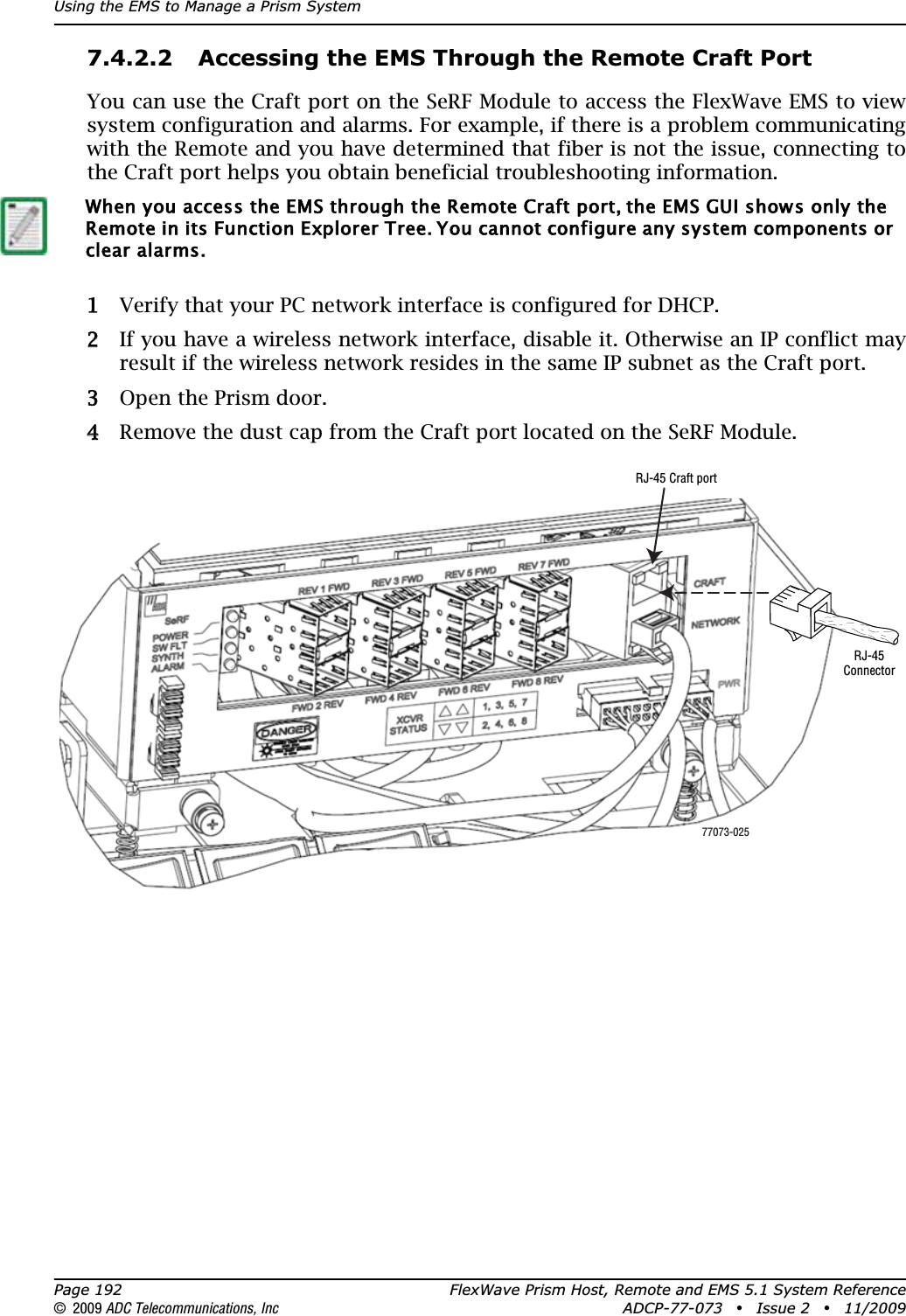
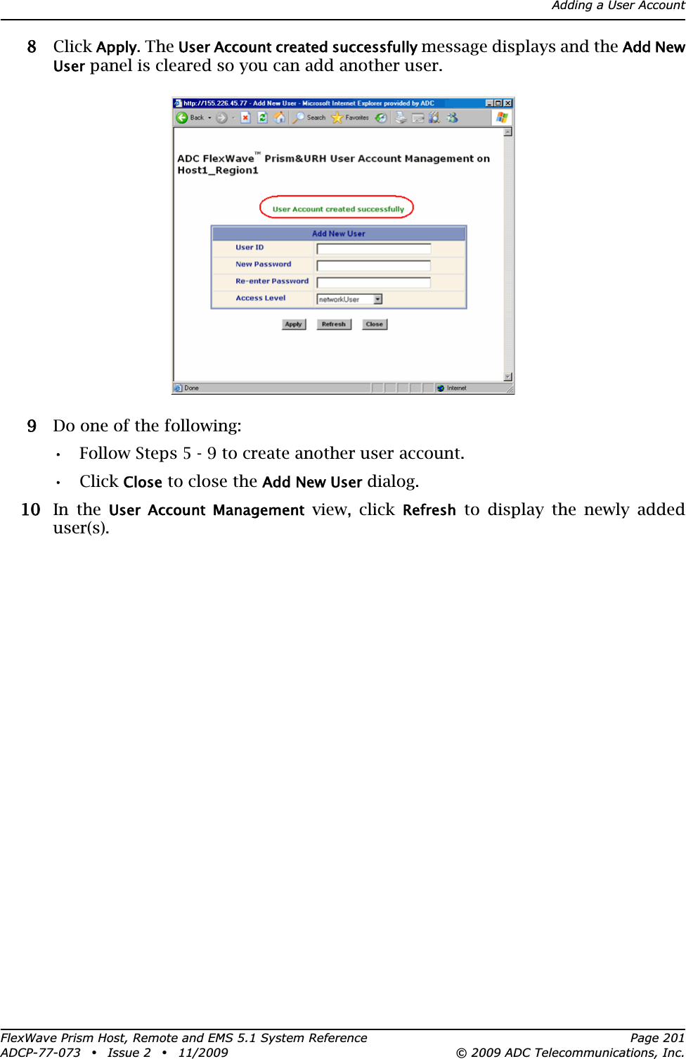
![Install any 40W RF Module(s)FlexWave Prism Host, Remote and EMS 5.1 System Reference Page 131ADCP-77-073 • Issue 2 • 11/2009 © 2009 ADC Telecommunications, Inc.4.4.9.2 Power Consumption TablesTable 4-2. SeRF Module Power ConsumptionSeRF ModulePower Consumption per ModuleNominal (W) @ 25C Maximum (W)SeRF Module (1 SFP)[add 1.25W for each SFP added]36 38Table 4-3. RF Module Power ConsumptionPrism RF Module DescriptionPower Consumption per ModuleNominal (W)@ 25C Maximum (W)Single or Dual SuperDARTRF Module10W GSM900 Non-Diversity 299 337Diversity 321 35915.8W GSM1800 Non-Diversity 299 33715.8W UMTS Non-Diversity 285 35020W PCS or 20W AWS Non-Diversity 299 368Classic DARTRF Module20W PCS or 20W AWS Non-Diversity 292 358Diversity 314 3816.5W CELL or 6.5W ESMRNon-Diversity 195 196Diversity 218 22020W CELL Non-Diversity 271 327Diversity 293 350](https://usermanual.wiki/ADC-Telecommunications/PRSM074C.Manual-part-2/User-Guide-1476800-Page-39.png)