ADC Telecommunications PRSM074C FlexWave™ Prism - 40 Watt 700 Upper C - Band User Manual 77073
ADC Telecommunications Inc FlexWave™ Prism - 40 Watt 700 Upper C - Band 77073
Contents
- 1. Prism Brochure
- 2. Manual part 1
- 3. Manual part 2
- 4. Manual part 3
Manual part 2

FlexWave Prism Host, Remote and EMS 5.1 System Reference Page 93
ADCP-77-073 • Issue 2 • 11/2009 ©2009 ADC Telecommunications, Inc.
4INSTALLING THE REMOTE UNIT
4.1 Remote Installation Overview ............................................................................. 94
4.1.1 Installation Hardware Provided with Remote.................................................. 94
4.1.2 Required Tools and Materials....................................................................... 95
4.2 Remote Mounting Plans...................................................................................... 96
4.3 Install the Remote............................................................................................. 97
4.3.1 Unpack and Inspect the Remote and Components .......................................... 97
4.3.2 Install the Remote RF Module(s) .................................................................. 98
4.4 Install any 40W RF Module(s) ............................................................................107
4.4.1 Prepare the Remote and RF Module.............................................................108
4.4.2 Remove Module Shelf(s)............................................................................108
4.4.3 Install the 40W RF Module .........................................................................110
4.4.4 Ground Wire Installation............................................................................118
4.4.5 Network Cable Installation .........................................................................119
4.4.6 Quad Fiber Cable Installation .....................................................................121
4.4.7 Antenna Cable Installation .........................................................................123
4.4.8 AC Power Wiring Installation ......................................................................125
4.4.9 Determine the Circuit Breaker or Fuse for Remote.........................................129
4.4.9.1 Power Consumption ..........................................................................129
4.4.9.2 Power Consumption Tables.................................................................131
4.4.10 Mount the Remote and Power Up ..............................................................132
Content Page

Installing the Remote Unit
Page 94 FlexWave Prism Host, Remote and EMS 5.1 System Reference
© 2009 ADC Telecommunications, Inc ADCP-77-073 • Issue 2 • 11/2009
4.1 REMOTE INSTALLATION OVERVIEW
Installation of the Remote consists of the following basic steps:
11 Unpack and inspect your shipment.
22 Install the RF module(s).
33 Connect the ProAx Fiber Cables.
44 Connect external coaxial antenna cables must be routed from the antenna to the
Remote TX0/RX0 and RX1 connectors.
55 Install the AC power cable and connect it the Remote’s AC power port and to an
external junction box .
4.1.1 Installation Hardware Provided with Remote
The installation hardware provided with the Remote is listed in Table 4-1.
To insure that all connectors and ports remain dust- free during installation, leave all
dust caps and dust protectors in place until directed to remove them.
Table 4-1. Remote Unit Installation Hardware
Item Quantity
AC Power Cable (15 feet/4.6m) 1
Quad Fiber Cable Assembly 1 (a)
(a) If the Remote has more than 2 SFPs, two Quad
Fiber Cable Assemblies are required.
3/8-inch hex standoff 3
3/8-inch 10-32 phillips screw 3
#10 split washer 3

Remote Installation Overview
FlexWave Prism Host, Remote and EMS 5.1 System Reference Page 95
ADCP-77-073 • Issue 2 • 11/2009 © 2009 ADC Telecommunications, Inc.
4.1.2 Required Tools and Materials
The following tools are required in order to complete the procedures in this
instruction:
•• Socket Wrench and 3/8-inch Deep Socket
•• Wire cutters
•• Wire stripper
•• Compression pliers for splicing grounding cable
•• Tools for installing exterior AC circuit
•• Tool kit for attaching N-Type connectors to coaxial cable
•• Fiber cleaning kit
The following materials are required in order to complete the installation procedures:
•• #6 AWG (4 mm) copper wire and splice
•• #10 ring terminal for attaching #6 grounding wire to bottom of unit
•• Connector for attaching #6 grounding wire to approved earth ground source
•• Junction box, conduit, fasteners, connectors, and wire to install an exterior AC
circuit.
•• N-Type male connectors
•• RJ-45 connector (if making a permanent external network cable connection)

Installing the Remote Unit
Page 96 FlexWave Prism Host, Remote and EMS 5.1 System Reference
© 2009 ADC Telecommunications, Inc ADCP-77-073 • Issue 2 • 11/2009
4.2 REMOTE MOUNTING PLANS
The FlexWave Prism Remote Unit has a low profile design that requires minimal real
estate for installation. The basic dimensions and weights of the Remote are listed in
Table 4-2.
The Prism Remote should be mounted on a utility pole, mast, or on a flat surface. A
mounting kit is available for each unit. Installation consists of securing the bracket
to the mounting surface (wood, concrete, or steel) and then hanging the unit from the
bracket. The Remote should only be mounted in a restricted access location.
Detailed instructions for mounting the FlexWave Prism Remote are in the Remote Unit
Mounting Kit Installation Instructions (ADCP-77-077).
Table 4-2. Remote Dimensions
Remote Configuration Depth Width Height Weight of Fully
Populated Units
Single- Band 10.51
"
12.15
"
22.50" <65 lbs
Double Band 10.51
"
12.15
"
30.50" <96 lbs
Triple Band 10.51
"
12.15
"
38.46" <127 lbs
Quad- Band 10.51
"
12.15
"
49.60" <165 lbs
Install the Remote
FlexWave Prism Host, Remote and EMS 5.1 System Reference Page 97
ADCP-77-073 • Issue 2 • 11/2009 © 2009 ADC Telecommunications, Inc.
4.3 INSTALL THE REMOTE
This chapter guides you through installing a Prism Remote, which requires 63 steps
that are divided into 9 sections. Follow the steps in the order in which they are
provided.
4.3.1 Unpack and Inspect the Remote and Components
This section provides instructions for opening the shipping boxes, verifying that all
parts have been received, and verifying that no shipping damage has occurred. Use
the following procedure to unpack and inspect the Host and any accessories:
Unpack and inspect the various components as follows:
11 Inspect the exterior of the shipping container(s) for evidence of rough handling
that may have damaged the components in the container.
22 Unpack each container while carefully checking the contents for damage and
verify with the packing slip.
33 If damage is found or parts are missing, file a claim with the commercial carrier
and notify ADC Customer Service (see “Contacting ADC” on page 335). Save the
damaged cartons for inspection by the carrier.
44 Save all shipping containers for use if the equipment requires shipment at a
future date.
This is restricted access equipment and only service personnel should open and operate
this equipment using appropriate tools
Wet conditions increase the potential for receiving an electrical shock when installing or
using electrically- powered equipment. To prevent electrical shock, never install or use
electrical equipment in a wet location or during a lightning storm.
Installation of the Remote may proceed separately from the installation of the
corresponding Host.

Installing the Remote Unit
Page 98 FlexWave Prism Host, Remote and EMS 5.1 System Reference
© 2009 ADC Telecommunications, Inc ADCP-77-073 • Issue 2 • 11/2009
4.3.2 Install the Remote RF Module(s)
The RF Module cables that are pre installed in the Remote connect to the
corresponding connectors on the RF Module. The RF Module cables correlate to the
antenna connectors on the bottom of the Remote chassis. The cables and connectors
have corresponding labels as shown in Table 4-3. The RF cable and connector labels
also correspond to the RF Module slots in the Remote chassis, where MOD A is the
bottom shelf and MOD D is the top shelf.
Table 4-3. RF Antenna Labels
Remote RF
Module
Shelf
RF Module Cable,
RF Module
Connector, and
Remote Antenna
Connector Labels
Function
MOD A Mod A TX0/RX0 Transmit RF power and primary receive to/from the antenna
for RF Module A
Mod A RX1 Diversity receive for RF power from the antenna for RF
Module A
MOD B Mod B TX0/RX0 Transmit RF power and primary receive to/from the antenna
for RF Module B
Mod B RX1 Diversity receive for RF power from the antenna for RF
Module B
MOD C Mod C TX0/RX0 Transmit RF power and primary receive to/from the antenna
for RF Module C
Mod C RX1 Diversity receive for RF power from the antenna for RF
Module C
MOD D Mod D TX0/RX0 Transmit RF power and primary receive to/from the antenna
for RF Module D
Mod D RX1 Diversity receive for RF power from the antenna for RF
Module D
Install the Remote
FlexWave Prism Host, Remote and EMS 5.1 System Reference Page 99
ADCP-77-073 • Issue 2 • 11/2009 © 2009 ADC Telecommunications, Inc.
In the following steps, the RF cables and connectors are referred to as
MOD
N
TX0/RX0
and as
MOD
N
TRX1
where
N
equals
A
,
B
,
C
, or
D
.
55 Unpack and inspect the RF Module as described in “Unpack and Inspect the
Remote and Components” on page 97.
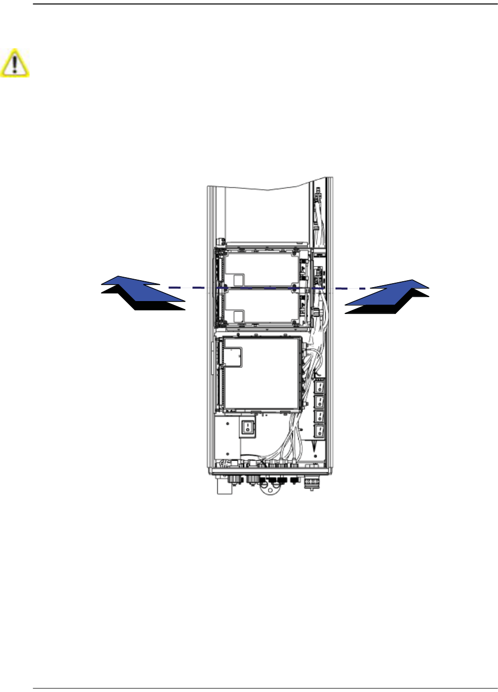
66 Open the Remote enclosure.
77 Remove release liners, if present, from the thermal pads on the RF Module prior
to installing the module into the Remote chassis.
Thermal pads are located as follows:
•• one large pad on the back surface (LPA)
•• up to two on the front surface (DARTs)
•• two on the left side for the (RDI).
88 Hold the RF Module so that the DART card(s) face away from the Remote and the
Mounting Hook is toward the Receiving flange on the Remote chassis.
Handle the RF Module with care during installation. Be especially careful to not damage
the thermal- interface material (TIM), which is attached to the LPA. If the TIM is damaged,
the LPA can overheat. Before installing the RF Module, check to see if the heatsink
material is gouged or cracked. If the TIM is damaged, do not install the RF Module and
contact ADC for assistance (see “Contacting ADC” on page 335 for contact information).
If the thermal- interface material is damaged, the installation and use of the RF Module
may void the warranty of the RF Module.
The thermal pads are very sensitive to mishandling—do not nick, scratch, or ding them.
Always install RF Modules from the bottom up and do not skip a shelf.
Installing the Remote Unit
Page 100 FlexWave Prism Host, Remote and EMS 5.1 System Reference
© 2009 ADC Telecommunications, Inc ADCP-77-073 • Issue 2 • 11/2009
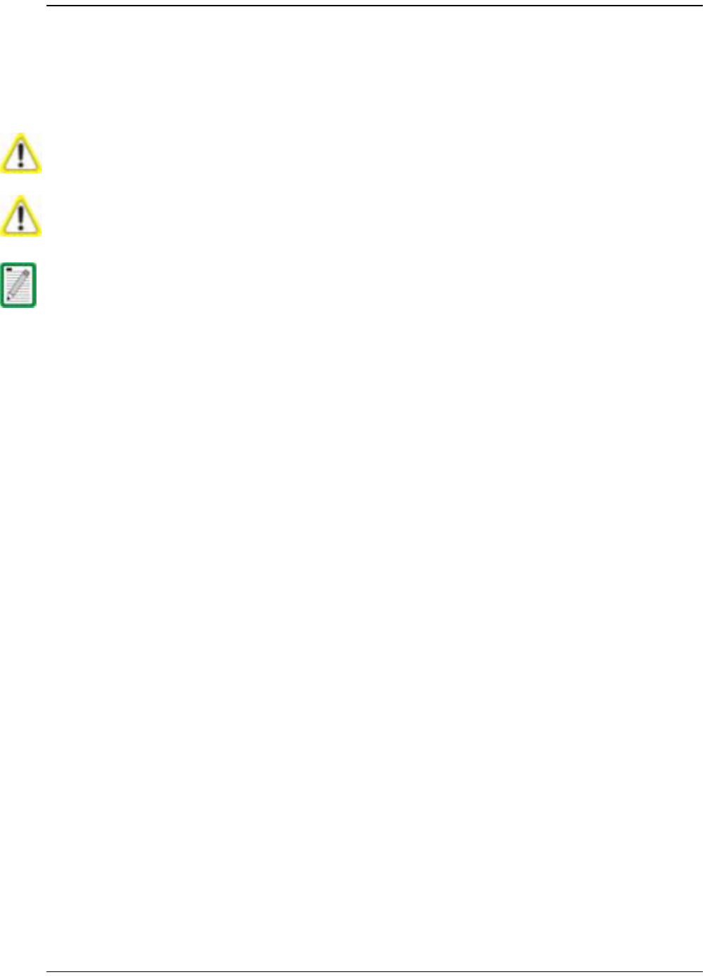
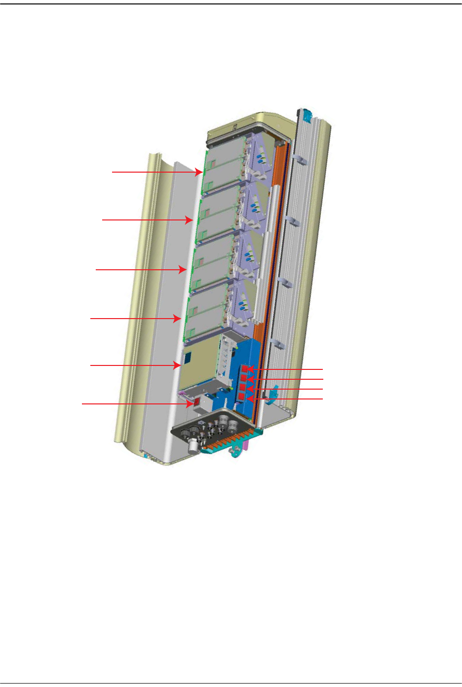
99 Holding the RF Module at a 45° angle in respect to the rear heatsink, rest the
bottom surface of the module on the RF Module shelf.
SeRF Module
MOD A
MOD B
MOD C
MOD D
77073-040
Install the Remote
FlexWave Prism Host, Remote and EMS 5.1 System Reference Page 101
ADCP-77-073 • Issue 2 • 11/2009 © 2009 ADC Telecommunications, Inc.
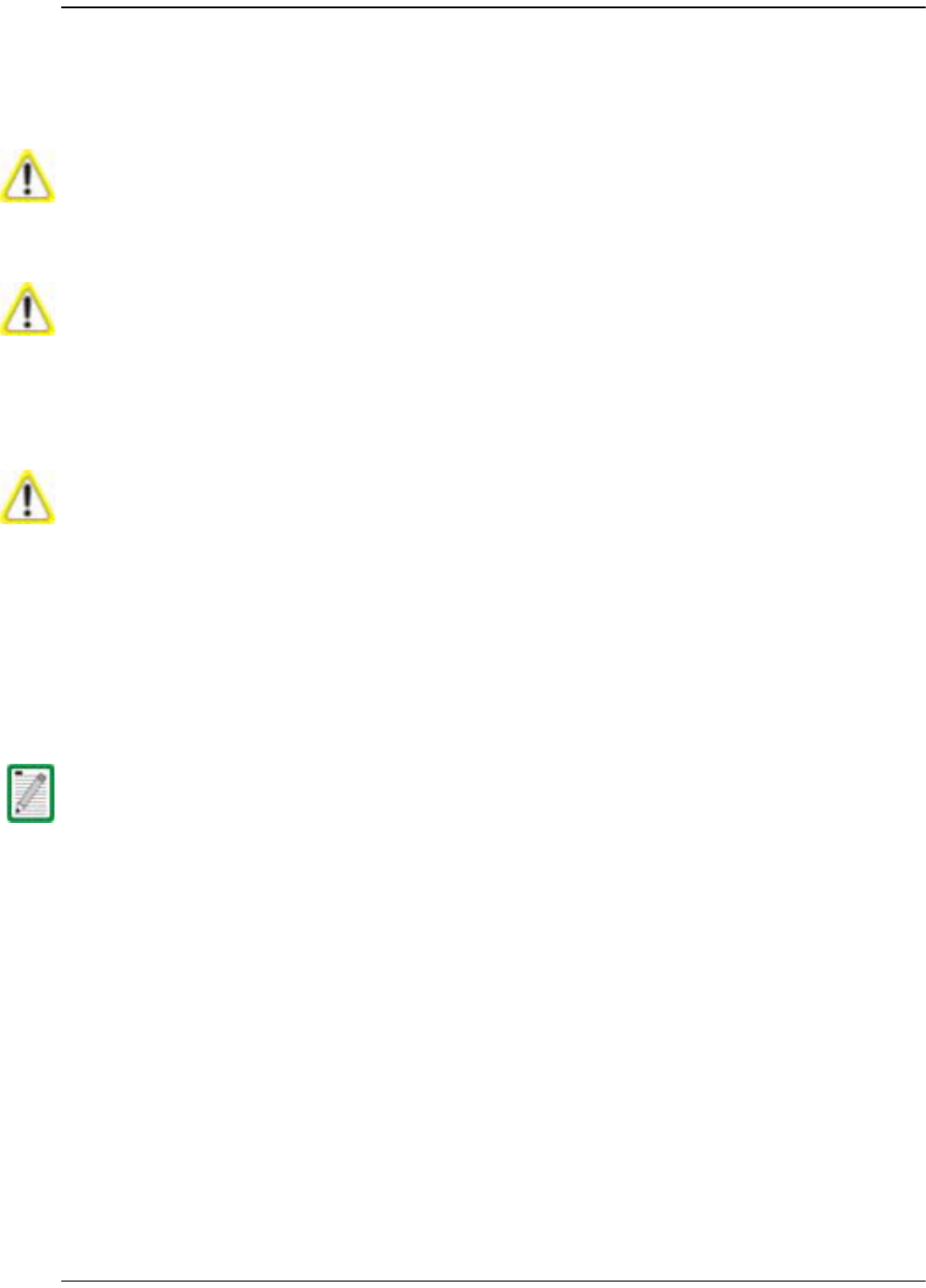
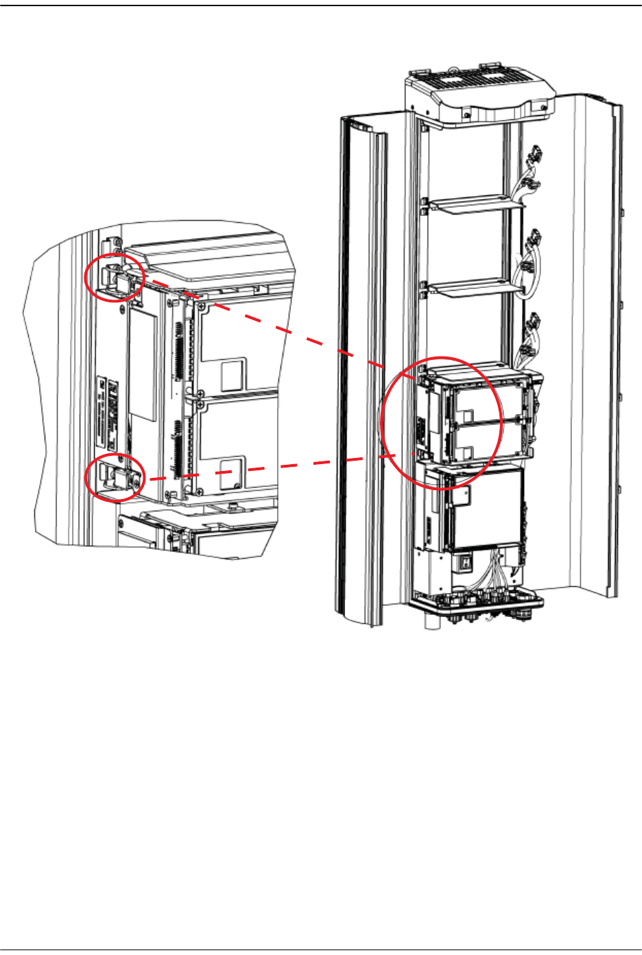
100 Aligning the mounting hook on the module with the receiving flange on the
Remote heat sink, and slide the RF Module in toward the flange until it can go no
further.
RF Module
Mounting hook
Chassis
Receiving
flange
77073-044
Installing the Remote Unit
Page 102 FlexWave Prism Host, Remote and EMS 5.1 System Reference
© 2009 ADC Telecommunications, Inc ADCP-77-073 • Issue 2 • 11/2009
111 Push the left edge of the RF Module back and into the Remote chassis until it can
go no further.
Make sure the RF Module is seated correctly in the Module shelf. Incorrect alignment of
the RF Module can cause the RF Module to fail due to over heating.
• The front edge of the RF Module should be parallel with the shelf above it.
• The Mounting hook on the RF Module should be fully engaged with the Receiving flange
on the Remote chassis.
• If you later cannot shut the Remote door, verify that the RF Module is installed
correctly.
77073-045
Install the Remote
FlexWave Prism Host, Remote and EMS 5.1 System Reference Page 103
ADCP-77-073 • Issue 2 • 11/2009 © 2009 ADC Telecommunications, Inc.
122 Secure the two module latches on the left side of the RF Module.
133 Verify that the RF Module Mounting hook is engaged correctly by pulling the
module away from the heat sink. The RF Module should not move. If the RF
Module moves during this check, repeat Step 9 on page 100 through Step 12.
144 Position the cables so that are under the right edge of the RF Module, pointing up.
77073-041

Installing the Remote Unit
Page 104 FlexWave Prism Host, Remote and EMS 5.1 System Reference
© 2009 ADC Telecommunications, Inc ADCP-77-073 • Issue 2 • 11/2009
155 Follow these rules when connecting the RF Module cables:
•• At each RF Module shelf, the Power (PWR) cable and two high-speed-data
cables will always be provided.
•• If you are installing a Non-Diversity Chassis, only one RF cable labeled
MOD
N
TX0/RX0
will be populated.
•• Always connect the high-speed-data cable labeled
DIV
. This protects against
the cable getting caught in the chassis door.
•• If you are installing a Diversity Chassis, both RF cables labeled
MOD
N
TX0/RX0
and
MOD
N
RX1
will be populated.
•• For Diversity modules, all cables are to be connected.
•• If you order a Non-Diversity RF Module and are installing it in a Diversity
chassis, connect it as if it was being installed into a Non-Diversity chassis.
•• When you order a Dual SuperDART module, connect both high-speed data
cables (
PRIM
and
DIV
) and the
RF TX0/RX0
cable.
•• Adhere to a minimum bend radius of 1" for all RF cables from the integrated
cable guide to the module.
•• Maintain adequate strain relief distances from connection points to the
module.
166 Working from the bottom connector up, connect the RF Module cables.
aa If this is a Diversity chassis, connect the RF Diversity cable labeled
MOD
N
RX1
to the
RX1
connector and turn the thumbscrew to secure the cable to the
chassis.
bb Connect the RF cable labeled
MOD
N
TX0/RX0
to the
TX0/RX0
connector and
turn the thumbscrew to secure the cable to the chassis.
cc Connect the
MOD N DIV
high-speed-data cable to the
DIV
connector. This
connects the Remote SeRF interface board (RSI) to the Diversity DART.
dd Connect the
MOD N PRIM
high-speed cable to the
PRIM
connector. This connects
the RSI to the Primary DART.
ee Connect the Power cable to the
PWR
connector. This connects the RF Module to
the DC power connection.
Always connect the Diversity high- speed- data cable, even for non- diversity modules.
This prevents the cable from getting caught between the chassis door and the RF
Module.
Install the Remote
FlexWave Prism Host, Remote and EMS 5.1 System Reference Page 105
ADCP-77-073 • Issue 2 • 11/2009 © 2009 ADC Telecommunications, Inc.
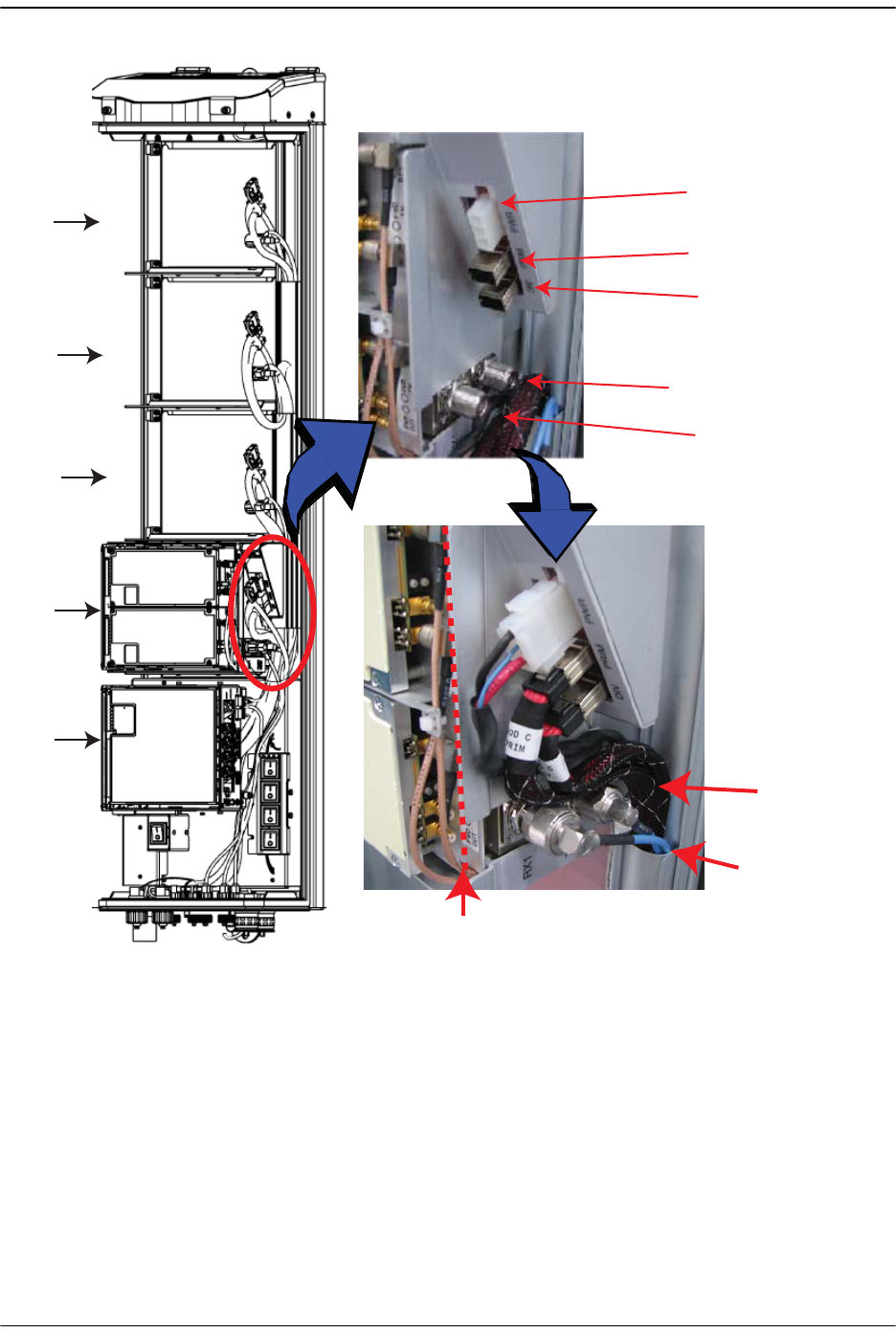
177 Ensure that all cable bends are below the top edge of the Connector Interface
Panel as indicated by the dashed line in the preceding figure. Failure to correctly
position the cables could inhibit closing the Remote door, which can result in
damage to the cables.
MOD A
MOD D
MOD C
MOD B
SeRF
Module
TX0/RX0
RX1
DIV
PRIM
PWR
77073-043
Note routing of
high-speed cables
Note bend
radii ≥ 1-inch
Edge of Connector Interface Panel
Installing the Remote Unit
Page 106 FlexWave Prism Host, Remote and EMS 5.1 System Reference
© 2009 ADC Telecommunications, Inc ADCP-77-073 • Issue 2 • 11/2009
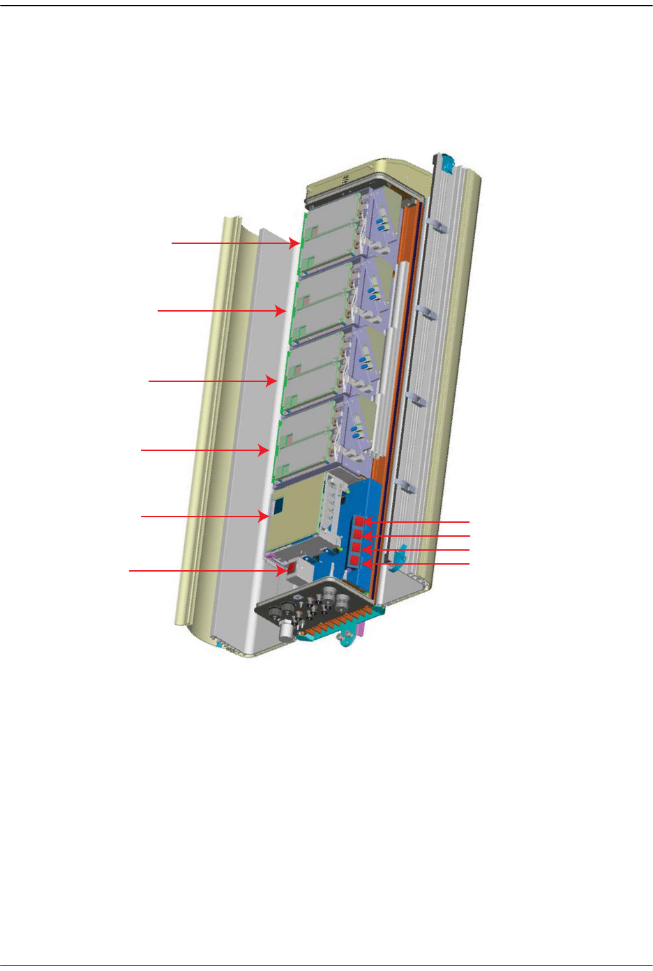
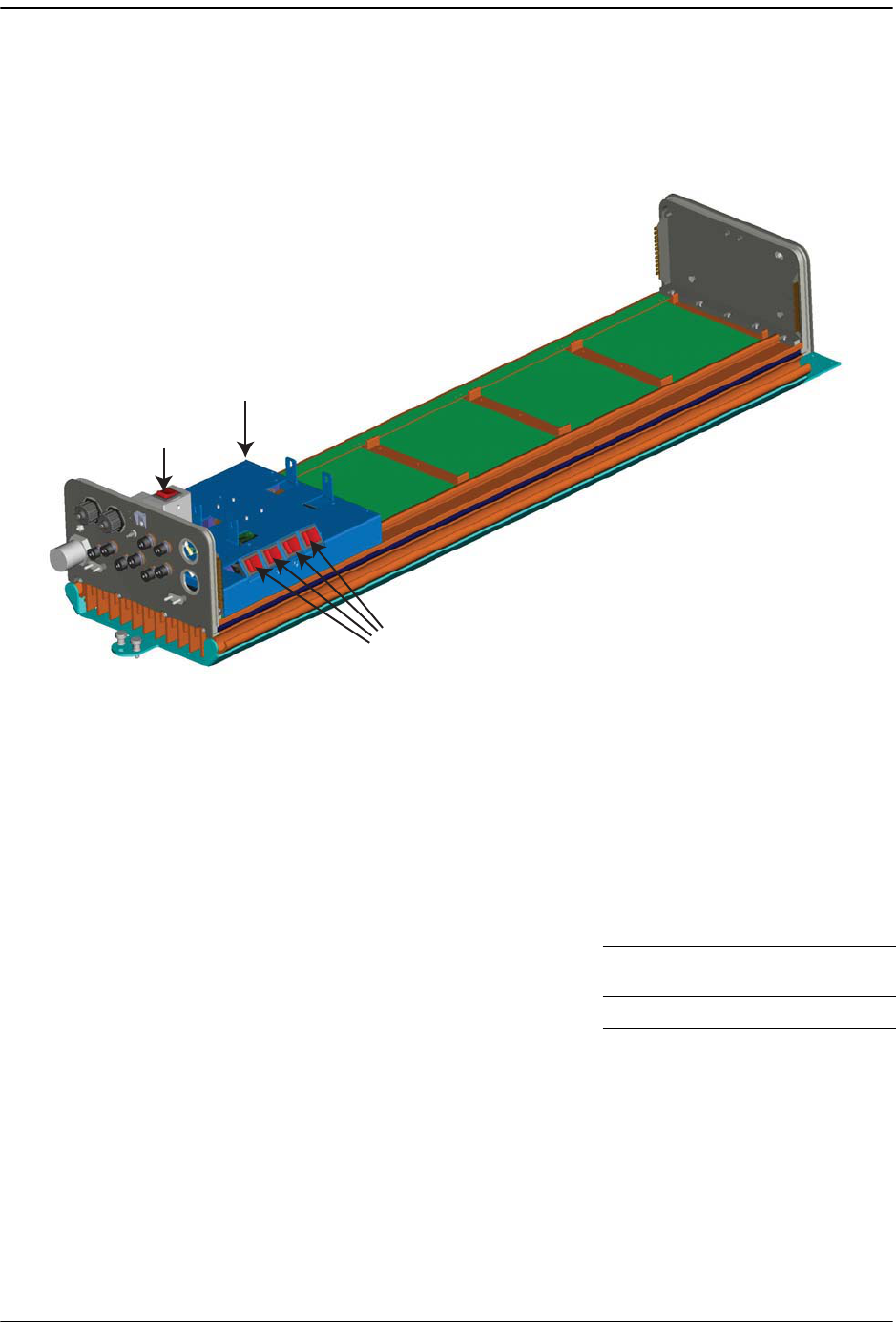
188 Toggle the Power switch that corresponds to the RF Module to its ON position.
199 Repeat Step 5 through Step 18 to install other RF Modules.
MOD A
SeRF
Module
AC Power
switch for
Remote
chassis
DC Power switch for Mod A
DC Power switch for Mod B
DC Power switch for Mod C
DC Power switch for Mod D
MOD B
MOD C
MOD D
77073-048

Install any 40W RF Module(s)
FlexWave Prism Host, Remote and EMS 5.1 System Reference Page 107
ADCP-77-073 • Issue 2 • 11/2009 © 2009 ADC Telecommunications, Inc.
4.4 INSTALL ANY 40W RF MODULE(S)
The RF Module cables that are preinstalled in the Remote connect to the
corresponding connectors on the RF Module. The RF Module cables correlate to the
antenna connectors on the bottom of the Remote chassis. The cables and connectors
have corresponding labels as shown in Table 4-3. The RF cable and connector labels
also correspond to the RF Module slots in the Remote chassis, where MOD A is the
bottom shelf and MOD D is the top shelf.
NOTE: In the following steps, the RF cables and connectors are referred to as MOD N TX0/RX0
and as MOD N TRX1 where N equals A,B,C, or D.
The 40W RF Modules can only be installed in the top most slots of the Remote:
• Slots A and B for a Dual-Band chassis.
• Slots B and C for a Tri-Band chassis
• Slots C and D for a Quad-Band chassis
Table 5. RF Antenna Labels for Dual-Slot Installations—From Top of Chassis Down
RF Module
Cable,
RF Module
Connector,
and Remote
Antenna
Connector
Labels (a)
(a) For dual-slot installations, the RF cables and connectors are labeled as MOD N TX0/RX0 and MOD N TX1, where N refers to the bottom slot of the
double-slot installation. For example, for a dual-slot installation in a Quad-Band chassis, the RF cables and connectors are labeled as MOD C
TX0/RX0 and MOD C TX1.
Function
Single-Slot
Remote RF
Module Shelf
Designations
Dual-Slot Remote RF Module Shelf Designations
Dual-Band Tri-Band Quad-Band
Mod D
TX0/RX0
Transmit RF power and primary receive
to/from the antenna for RF Module D MOD D N/A N/A
MOD C
Mod D RX1 Diversity receive for RF power from the
antenna for RF Module D
Mod C
TX0/RX0
Transmit RF power and primary receive
to/from the antenna for RF Module C MOD C N/A
MOD B
Mod C RX1 Diversity receive for RF power from the
antenna for RF Module C
Mod B
TX0/RX0
Transmit RF power and primary receive
to/from the antenna for RF Module B MOD B
MOD A
MOD B
Mod B RX1 Diversity receive for RF power from the
antenna for RF Module B
Mod A
TX0/RX0
Transmit RF power and primary receive
to/from the antenna for RF Module A MOD A MOD A MOD A
Mod A RX1 Diversity receive for RF power from the
antenna for RF Module A

Installing the Remote Unit
Page 108 FlexWave Prism Host, Remote and EMS 5.1 System Reference
© 2009 ADC Telecommunications, Inc ADCP-77-073 • Issue 2 • 11/2009
4.4.1 Prepare the Remote and RF Module
1Unpack and inspect the RF Module as described in “Unpack and Inspect the
Remote and Components” on page 97.
2Open the Remote enclosure.
3Remove release liners, if present, from the thermal pads on the RF Module prior
to installing the module into the Remote chassis.
CAUTION! The thermal pads are very sensitive to mishandling—do not nick, scratch, or ding them.
Thermal pads are located as follows:
•one large pad on the back surface (LPA)
•up to two on the front surface (DARTs)
•one on the left side for the (RDI).
4.4.2 Remove Module Shelf(s)
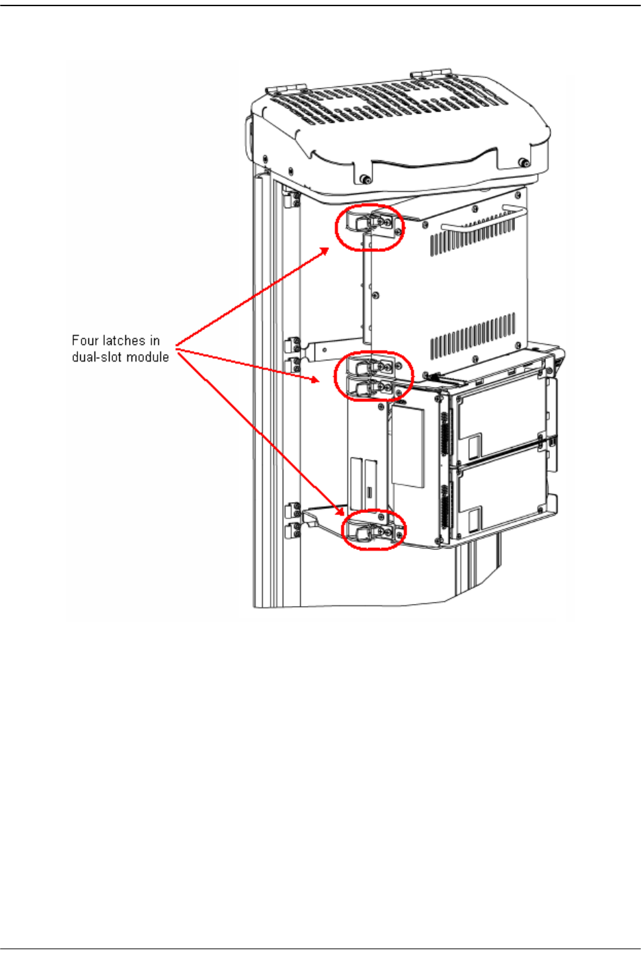
The module shelf for the upper module as defined in Table 4-3 on page 98 must
be removed prior to installation of the dual-slot module:
•Module D Shelf for a Quad-Band chassis
•Module C Shelf for a Tri-Band chassis
•Module B Shelf for a Dual-Band chassis
Handle the RF Module with care during installation. Be especially careful to not damage the thermal-interface
material (TIM), which is attached to the LPA. If the TIM is damaged, the LPA can overheat. Before installing the
RF Module, check to see if the heatsink material is gouged or cracked. If the TIM is damaged, do not install the
RF Module and contact ADC for assistance (see “Contacting ADC” on page 335 for contact information).
If the thermal-interface material is damaged, the installation and use of the RF Module may void the warranty
of the RF Module.
Install any 40W RF Module(s)
FlexWave Prism Host, Remote and EMS 5.1 System Reference Page 109
ADCP-77-073 • Issue 2 • 11/2009 © 2009 ADC Telecommunications, Inc.
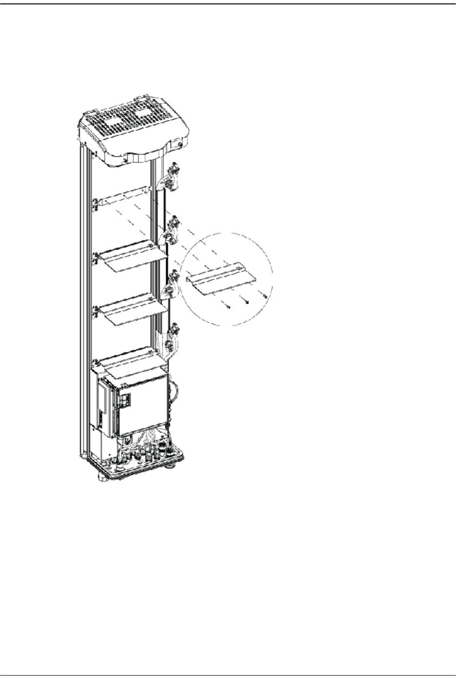
4Remove the module shelf:
aUse a 9/64” Allen™ wrench to remove the three screws that attach the
module shelf to the Remote chassis, as shown in the following graphic.
bDiscard or store the module shelf and fasteners.
Use 9/64” Allen wrench to
remove the three Module Shelf screws
77072-003
Installing the Remote Unit
Page 110 FlexWave Prism Host, Remote and EMS 5.1 System Reference
© 2009 ADC Telecommunications, Inc ADCP-77-073 • Issue 2 • 11/2009
4.4.3 Install the 40W RF Module
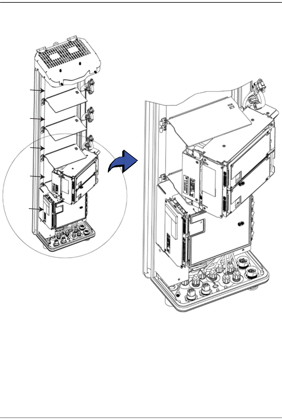
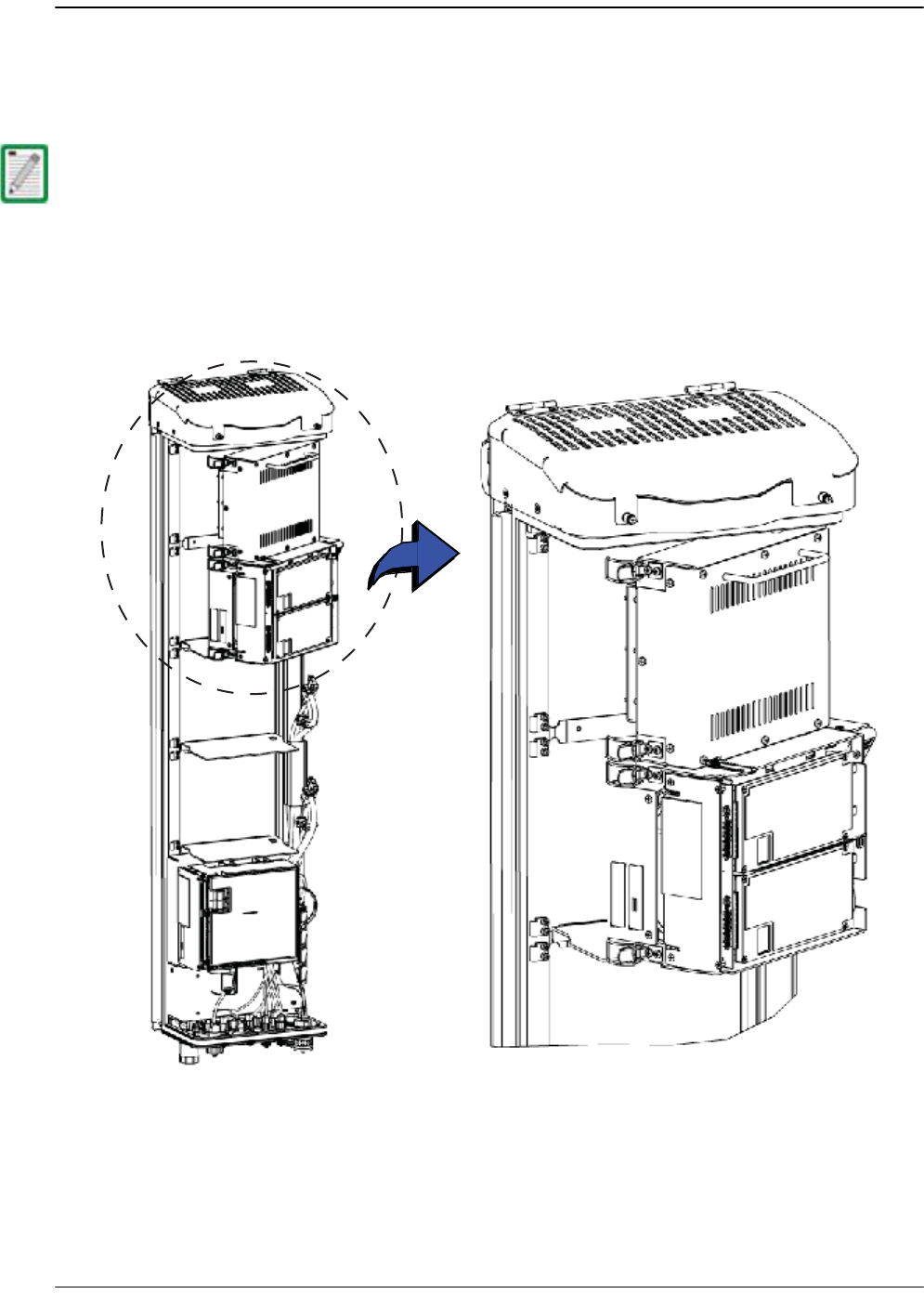
11 Hold the RF Module so that the DART card(s) face away from the Remote and the
Mounting Hook is toward the Receiving flange on the Remote chassis.
22 Holding the RF Module at a 45° angle in respect to the rear heatsink, rest the
bottom surface of the module on the RF Module shelf, as shown below:
Always install RF Modules from the bottom up and do not skip a shelf.
Installing a dual-slot RF Module
77072-004
Install any 40W RF Module(s)
FlexWave Prism Host, Remote and EMS 5.1 System Reference Page 111
ADCP-77-073 • Issue 2 • 11/2009 © 2009 ADC Telecommunications, Inc.
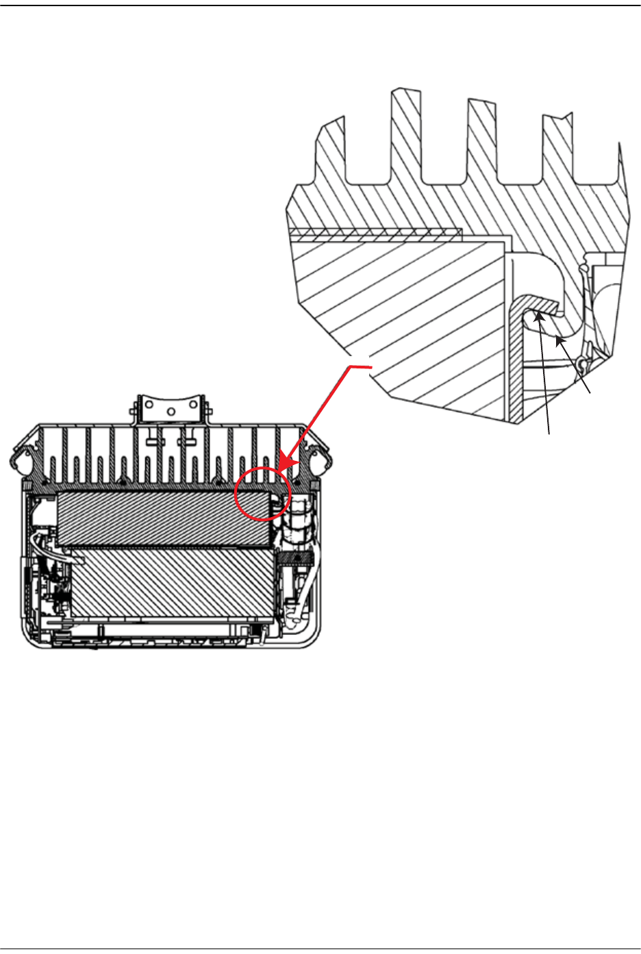
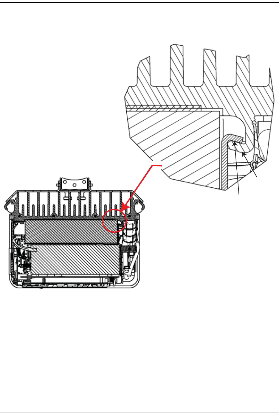
3Aligning the mounting hook on the module with the receiving flange on the
Remote heat sink, and slide the RF Module in toward the flange until it can go
no further.
RF Module
Mounting hook
Chassis
Receiving
flange
77073-044
Installing the Remote Unit
Page 112 FlexWave Prism Host, Remote and EMS 5.1 System Reference
© 2009 ADC Telecommunications, Inc ADCP-77-073 • Issue 2 • 11/2009
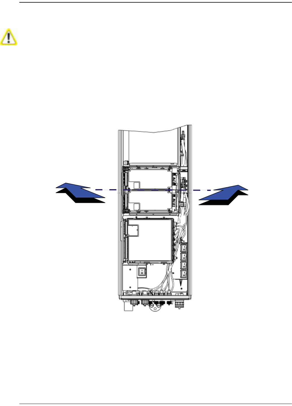
4Push the left edge of the RF Module back and into the Remote chassis until it
can go no further.
Make sure the RF Module is seated correctly in the Module shelf. Incorrect alignment of the RF Module can
cause the RF Module to fail due to over heating.
• The front edge of the RF Module should be parallel with the shelf above it.
• The Mounting hook on the RF Module should be fully engaged with the Receiving flange on the Remote
chassis.
• If you later cannot shut the Remote door, verify that the RF Module is installed correctly.
77072-008
In Steps 9 and 10, you engaged the right side of the RF Module with the Remote chassis.
In Step 11, you set the left edge of the RF Module into the Remote chassis.
By the end of Step 11, the front edge of the RF Module should be parallel with the shelf above it.
Now in Step 12, you are pushing the RF Module back into the chassis until it can go no further.
Install any 40W RF Module(s)
FlexWave Prism Host, Remote and EMS 5.1 System Reference Page 113
ADCP-77-073 • Issue 2 • 11/2009 © 2009 ADC Telecommunications, Inc.
5Secure the four module latches on the left side of the RF Module.
6Verify that the RF Module Mounting hook is engaged correctly by pulling the
module away from the heat sink. The RF Module should not move. If the RF
Module moves during this check, repeat Step 9 on page 100 through Step 12.
7Position the cables so that are under the right edge of the RF Module, pointing
up.

Installing the Remote Unit
Page 114 FlexWave Prism Host, Remote and EMS 5.1 System Reference
© 2009 ADC Telecommunications, Inc ADCP-77-073 • Issue 2 • 11/2009
8Follow these rules when connecting the RF Module cables:
•At each RF Module shelf, the Power (PWR) cable and two high-speed-data
cables will always be provided.
•If you are installing a module into a Non-Diversity Chassis, only one RF
cable labeled MOD N TX0/RX0 will be populated.
•High-speed data cables labeled PRIM and DIV should always either be
connected or strain relieved to adjacent cables. This protects against the
cable getting caught in the chassis door.
•If you order a Non-Diversity RF Module and are installing it in a Diversity
chassis, connect it as if it was being installed into a Non-Diversity chassis.
•Connect both high-speed data cables (PRIM and DIV) and the RF TX0/RX0
cable.
•Adhere to a minimum bend radius of 1" for all RF cables from the integrated
cable guide to the module.
•Maintain adequate strain relief distances from connection points to the
module.
•When installing dual-slot RF modules:
– The upper RF Module shelf will either not be present (factory installed
module) or will be removed prior to installation (field installed module).
– For dual-slot modules, only the RF cable labeled MOD N TX0/RX0 on the
lower module slot will be connected to the module connector TX0/RX0.
–The MOD N RX1 cable should be secured to the cable bundle using the
provided cable tie.
– Ensure that the MOD N RX1 cable and connector are secured so that they
will not be pinched or prevent the Remote door from closing.
– The Power (PWR) cable and two high-speed-data cables of the upper RF
Module slot will not be used. Connect the RF cable labeled MOD N RX1 to
the connector labeled N/C on the upper half of the double-slot module.
Use one of the provided cable ties to secure the MOD N TX0/RX0 RF cable,
both high-speed data cables and the Power (PWR) cable to the RF cable
labeled MOD N RX1, ensuring that the cable bundle will not be pinched or
prevent the Remote door from closing.

Install any 40W RF Module(s)
FlexWave Prism Host, Remote and EMS 5.1 System Reference Page 115
ADCP-77-073 • Issue 2 • 11/2009 © 2009 ADC Telecommunications, Inc.
9Working from the bottom connector up, connect the RF Module cables.
aConnect the RF cable labeled MOD N TX0/RX0 to the TX0/RX0 connector and turn
the thumbscrew to secure the cable to the chassis.
bConnect the MOD N PRIM high-speed cable to the PRIM connector. This
connects the RSI to the Primary DART.
cConnect the Power cable to the PWR connector. This connects the RF Module
to the DC power connection.
dThe Power (PWR) cable and two high-speed-data cables of the upper RF
Module shelf are not be used in a dual-slot installation. Connect the RF cable
labeled MOD N RX1 of the upper RF Module shelf to the connector labeled N/C
on the upper half of the dual-slot module. Use one of the provided cable
ties to secure the MOD N TX0/RX0 RF cable, both high-speed data cables and
the Power (PWR) cable to the RF cable labeled MOD N RX1, ensuring that the
cable bundle will not be pinched or prevent the Remote door from closing.
Always connect the Diversity high-speed-data cable, even for non-diversity modules. This prevents the cable
from getting caught between the chassis door and the RF Module.
Installing the Remote Unit
Page 116 FlexWave Prism Host, Remote and EMS 5.1 System Reference
© 2009 ADC Telecommunications, Inc ADCP-77-073 • Issue 2 • 11/2009
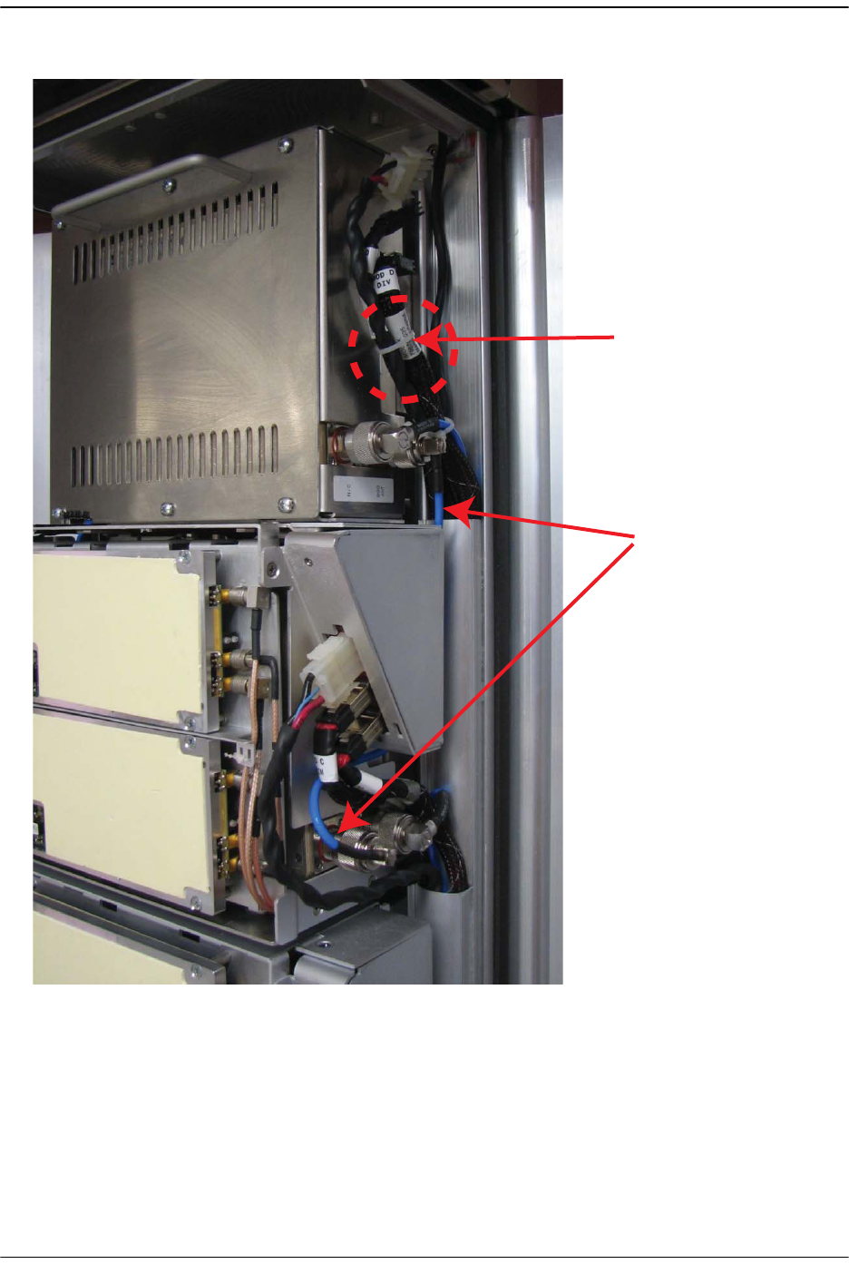
The following graphic shows cable connections for a dual-slot RF Module.
10 Ensure that all cable bends are below the top edge of the Connector Interface
Panel as indicated by the dashed line in the preceding figure. Failure to
correctly position the cables could inhibit closing the Remote door, which can
result in damage to the cables.
Cable connections
for a dual-slot RF Module
Tie wrap
Factory-installed
RX1 cable
77072-007
Install any 40W RF Module(s)
FlexWave Prism Host, Remote and EMS 5.1 System Reference Page 117
ADCP-77-073 • Issue 2 • 11/2009 © 2009 ADC Telecommunications, Inc.
11 Toggle the Power switch that corresponds to the RF Module to its ON position.
MOD A
SeRF
Module
AC Power
switch for
Remote
chassis
DC Power switch for Mod A
DC Power switch for Mod B
DC Power switch for Mod C
DC Power switch for Mod D
MOD B
MOD C
MOD D
77079-002
For Dual-Card RF Modules, use the
Power switch for the lower module.
For example, to power up a
Dual-Card RF Module in combined
slots C+D in a Quad-Band chassis,
turn ON DC Power switch for Mod C;
leave the DC Power switch for Mod D OFF.
Installing the Remote Unit
Page 118 FlexWave Prism Host, Remote and EMS 5.1 System Reference
© 2009 ADC Telecommunications, Inc ADCP-77-073 • Issue 2 • 11/2009
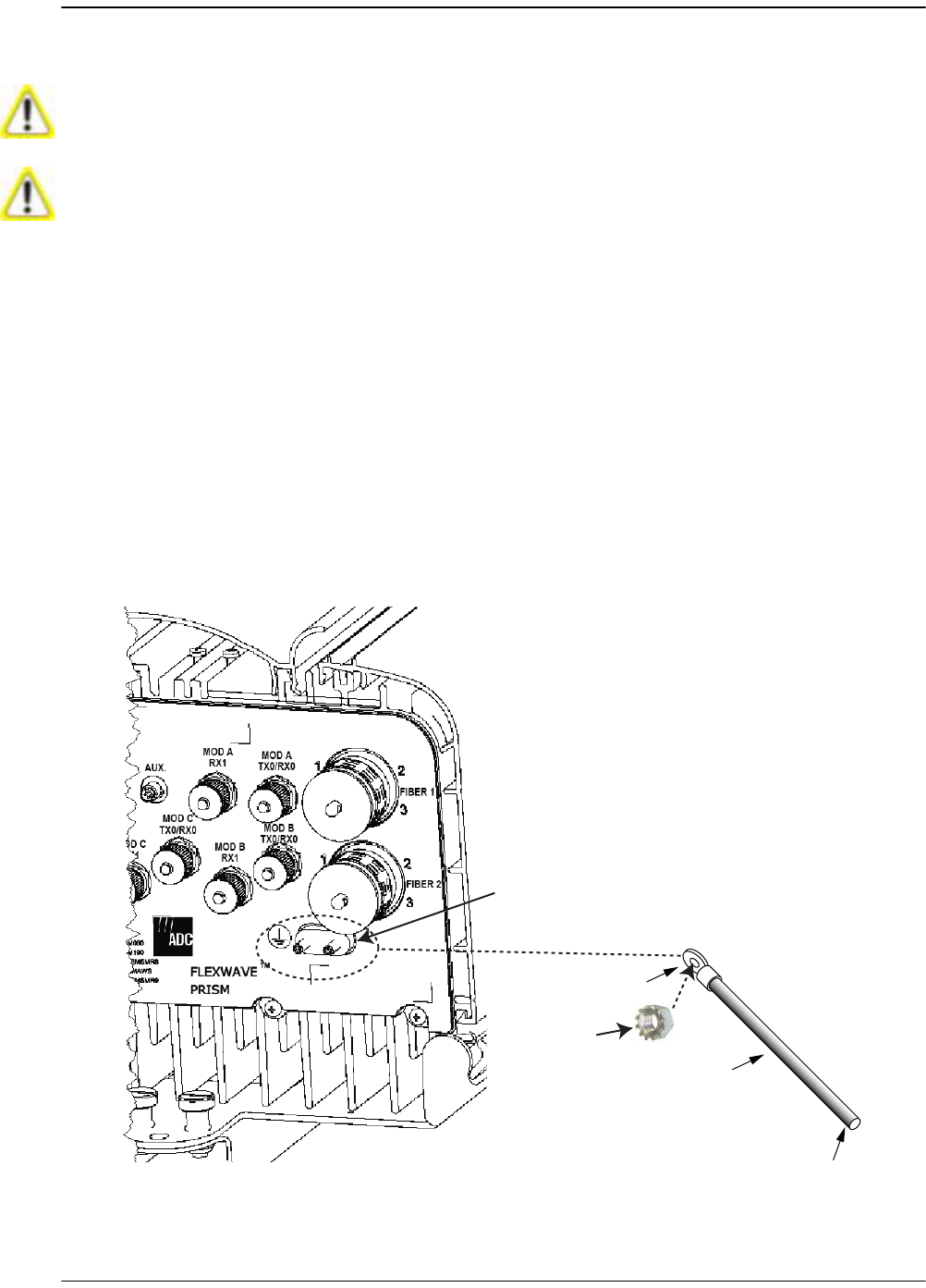
4.4.4 Ground Wire Installation
122 Locate a #6 AWG (4 mm) copper grounding wire long enough to reach an approved
earth ground.
133 Use a socket wrench with a 3/8-inch deep socket to remove the two 10-32 Keps
Nuts from the Remote’s Dual-Ground connector.
144 Secure the ring terminal end of the grounding wire to the ground studs on the unit
using the two 10-32 Keps Nuts removed in Step 13, and then torque the nuts to
18 in-lbs ± 1 in-lb.
155 Route the free end of the grounding wire to an approved earth ground source.
166 Cut the ground wire to length and connect it to the earth ground source as
specified by local code or practice.
Avoid sharp bends in the ground wire.
For proper and safe equipment operation, use a #6 copper wire terminated with the
provided ring terminal to link the Remote to an earth- ground source.
Partial Bottom View
Dual-Ground Connector
77073-014
To Earth Ground
Ground Wire
10-32 Keps Nut
Ring Terminal
Install any 40W RF Module(s)
FlexWave Prism Host, Remote and EMS 5.1 System Reference Page 119
ADCP-77-073 • Issue 2 • 11/2009 © 2009 ADC Telecommunications, Inc.
4.4.5 Network Cable Installation
The Remote provides a Network port allowing communications with the internal
processor and transfer of service data to the optical protocol allowing IP servicing
between the Host and Remote(s). That is, this provides a LAN extension to the Host
network. The Network port is 10/100/1000 BASE-T/TX (802.3ab compliant) MDI and
requires a minimum of CAT 5 cable.
The network cable must be terminated with a hardened RJ-45 male connector for
connection to the Network port. The maximum cable length is 300 feet (91.4 m).
Use the following procedure to install the Network cable:
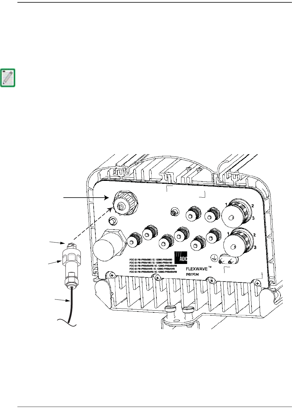
177 Remove the dust cap from the RJ-45 connector located at the bottom of the
Remote.
188 Route the network cable from the network connection to the underside of the
Remote.
199 Align the plug end of the RJ-45 cable connector with the RJ-45 port receptacle and
then insert the cable plug into the port receptacle.
Although the interface might provide GigE, only 100 Mbps is provided for bandwidth
between the Host and Remote.
NETWORK
AUX.
MOD A
RX1
MOD A
TX0/RX0
FIBER 1
FIBER 2
MOD B
TX0/RX0
MOD B
RX1
MOD C
TX0/RX0
MOD D
TX0/RX0
MOD C
RX1
MOD D
RX1
POWER
100-240 VAC
50-60 Hz
16 AMPS
RJ-45 Network
Connector port
Network cable
Connector nut
RJ-45 plug
Bottom View
77073-010

Installing the Remote Unit
Page 120 FlexWave Prism Host, Remote and EMS 5.1 System Reference
© 2009 ADC Telecommunications, Inc ADCP-77-073 • Issue 2 • 11/2009
200 Slide the connector nut up to the port until it engages the connector locking
mechanism.
211 Tighten the connector nut in a clockwise direction (if necessary, use a wrench or
pliers to grip the connector nut) until it snaps past the indented position and
locks into place. It may be necessary to apply 30 to 50 in-lbs (3.4 to 5.6 Nm) of
torque to the connector nut in order to turn it past the indented position.
Install any 40W RF Module(s)
FlexWave Prism Host, Remote and EMS 5.1 System Reference Page 121
ADCP-77-073 • Issue 2 • 11/2009 © 2009 ADC Telecommunications, Inc.
4.4.6 Quad Fiber Cable Installation
The Prism Remote ships with 10 meters of environmentally hardened cable with 1
meter of exposed, un-terminated single-mode 900μm optical fiber sufficient for
splicing in an Outside Plant (OSP) splice tray. The fiber cable connector is a BX5 4-port
fiber connector.
Use the following procedure to install the fiber cables:
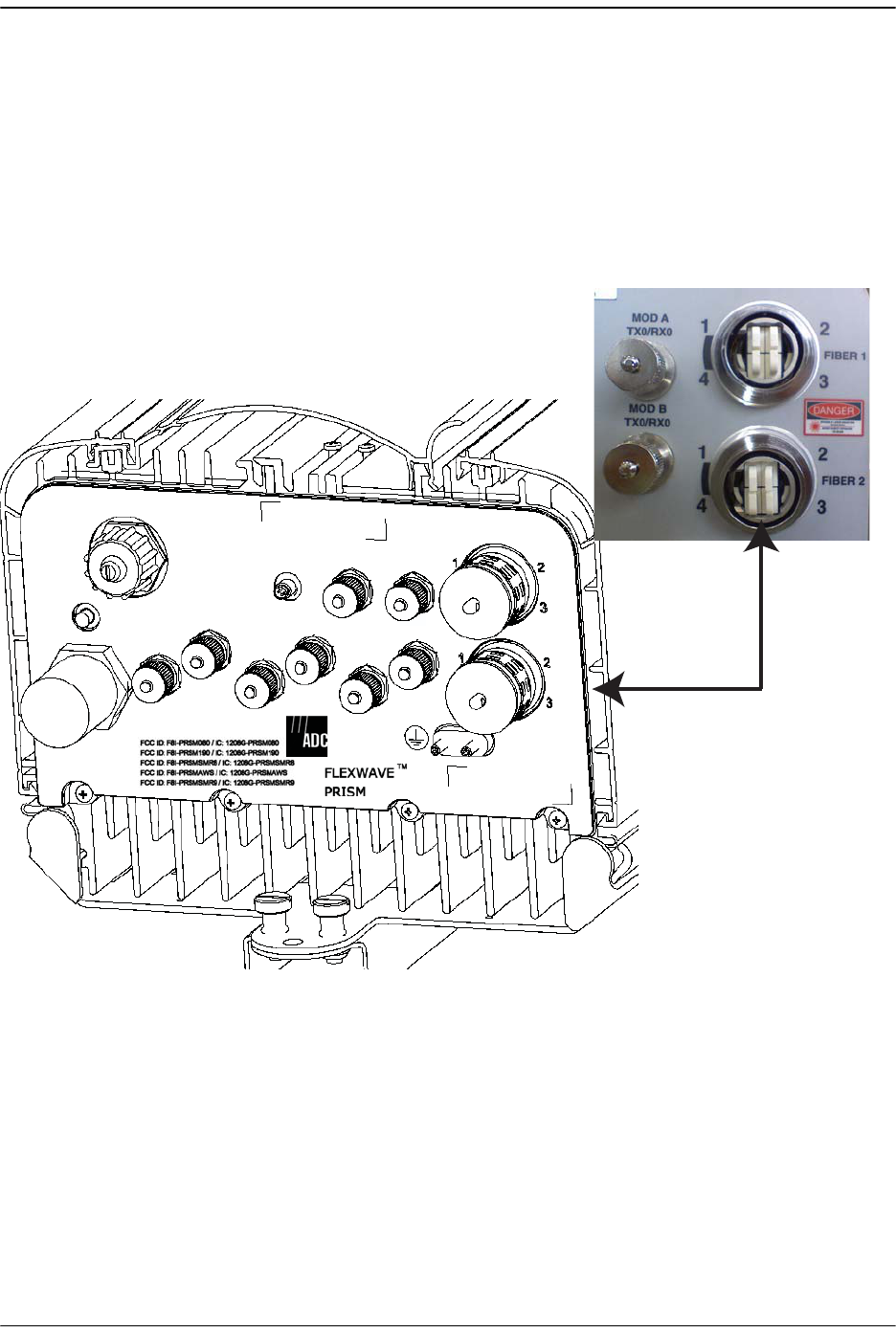
222 Remove ProAx connector dust cover located at the bottom of the Remote.
NETWORK
AUX.
MOD A
RX1
MOD A
TX0/RX0
FIBER 1
FIBER 2
MOD B
TX0/RX0
MOD B
RX1
MOD C
TX0/RX0
MOD D
TX0/RX0
MOD C
RX1
MOD D
RX1
POWER
100-240 VAC
50-60 Hz
16 AMPS
77073-011
Fiber 2 is a
ProAx connector
that comprises
4 BX5 connectors.
Bottom View
Installing the Remote Unit
Page 122 FlexWave Prism Host, Remote and EMS 5.1 System Reference
© 2009 ADC Telecommunications, Inc ADCP-77-073 • Issue 2 • 11/2009
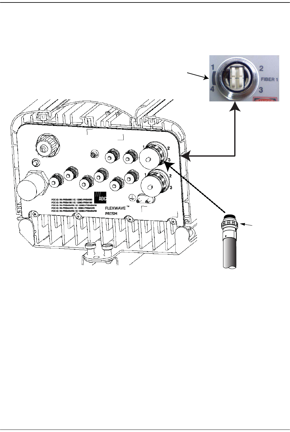
233 Remove the dust cap from the fiber cable BX5 connector (FIBER 1).
244 Align the plug end of the BX5 cable connector with the BX5 port receptacle and
then insert the cable plug into the port receptacle as shown below, and then slide
the strain relief boot over the connector.
NETWORK
AUX.
MOD A
RX1
MOD A
TX0/RX0
FIBER 1
FIBER 2
MOD B
TX0/RX0
MOD B
RX1
MOD C
TX0/RX0
MOD D
TX0/RX0
MOD C
RX1
MOD D
RX1
POWER
100-240 VAC
50-60 Hz
16 AMPS
BX5 CABLE
CONNECTOR
77073-012
Fiber 1 is a
ProAx connector
that comprises
4 BX5 connectors
Bottom View
Shaded area is the
Alignment Key for
the BX5 cable
connector
Install any 40W RF Module(s)
FlexWave Prism Host, Remote and EMS 5.1 System Reference Page 123
ADCP-77-073 • Issue 2 • 11/2009 © 2009 ADC Telecommunications, Inc.
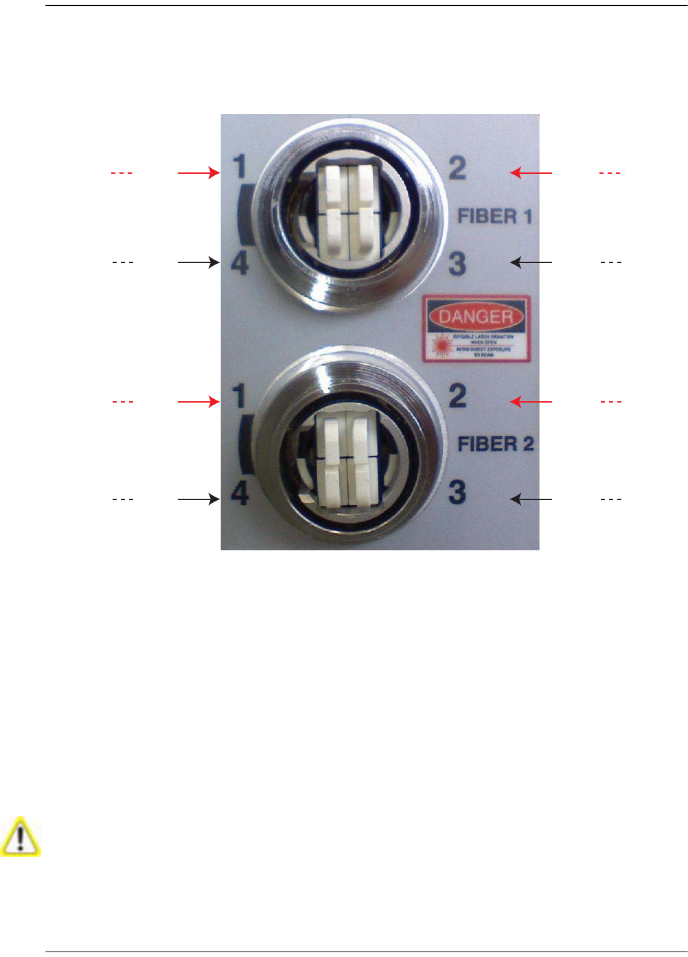
255 Route the fiber cable from the underside of the Remote to the OSP box. Observe
the fiber numbers and their positions in the quad cable connector as shown
below. The fibers at the other end of the fiber cable are numbered with the same
numbering scheme.
266 Secure fiber cable in place following local practices.
277 If a second fiber cable assembly is required (for example, your Prism system has
three SFPs to handle up to 280 MHz of RF bandwidth), complete Step 22 through
Step 26 to add the second fiber cable assembly, only this time, connect to the
Fiber 2 ProAx connector located at the bottom of the Remote as shown in Step 22.
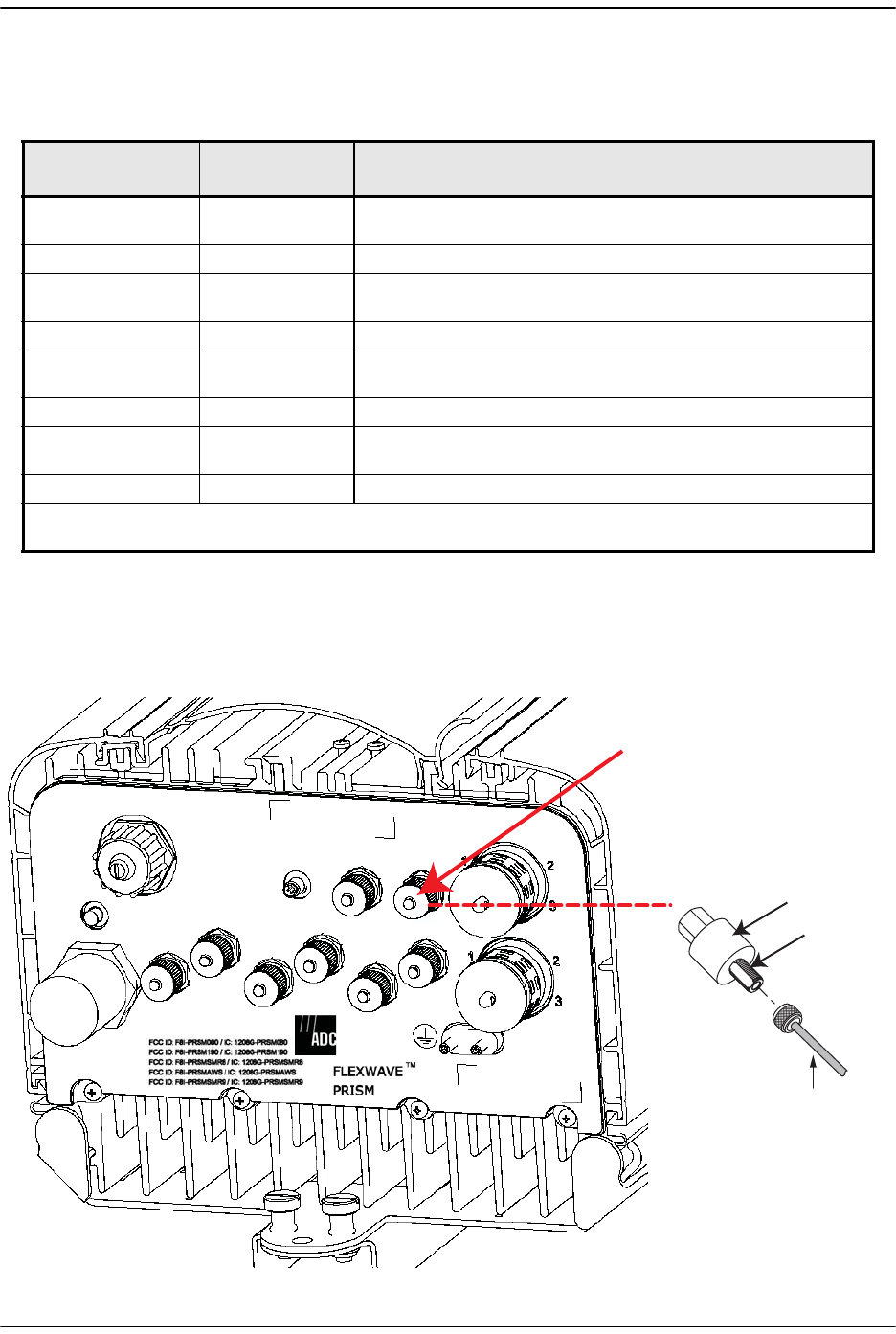
4.4.7 Antenna Cable Installation
Coaxial antenna cables must be routed from the antenna to the Prism Remote. The
cables must be terminated with an N-Type male connector for connection to the
Remote antenna port or the lightning surge suppressor (accessory).
To comply with Maximum Permissible Exposure (MPE) requirements, the maximum
composite output from the antenna cannot exceed 1640 Watts EIRP and the antenna
must be permanently installed in a fixed location that provides at least 6 meters (20 feet)
of separation from all persons.
REV
Fiber 4
SFP2SFP2
77073=047
SFP3SFP3 FWD
Fiber 1
SFP1SFP1 FWD
Fiber 1 SFP1SFP1
REV
Fiber 2
SFP3SFP3
REV
Fiber 2
SFP2SFP2
FWD
Fiber 3
SFP4SFP4
FWD
Fiber 3
SFP4SFP4 REV
Fiber 4
Installing the Remote Unit
Page 124 FlexWave Prism Host, Remote and EMS 5.1 System Reference
© 2009 ADC Telecommunications, Inc ADCP-77-073 • Issue 2 • 11/2009
Refer to Table 4-1 for the relationship between antenna numbers and Remote RF
modules.
Use the following procedure to install the antenna cable(s):
288 Remove the dust cap from the N-type female connector located on the underside
of the unit as shown below.
Table 4-1. Antenna Connectors
Antenna
Connector Label
RF Module Function of Connection Point
Mod A TX0/RX02RF Module A Transmit RF power and primary receive to/from the
antenna
Mod A RX1 RF Module A Diversity receive for RF power from the antenna
Mod B TX0/RX0 RF Module B Transmit RF power and primary receive to/from the
antenna
Mod B RX1 RF Module B Diversity receive for RF power from the antenna
Mod C TX0/RX0 RF Module C Transmit RF power and primary receive to/from the
antenna
Mod C RX1 RF Module C Diversity receive for RF power from the antenna
Mod D TX0/RX0 RF Module D Transmit RF power and primary receive to/from the
antenna
Mod D RX1 RF Module D Diversity receive for RF power from the antenna
2Mod A/RF Module A is the bottommost Module in a Remote and Mod D/RF Module D is the
topmost module in a Quad-Band Remote.
NETWORK
AUX.
MOD A
RX1
MOD A
TX0/RX0
FIBER 1
FIBER 2
MOD B
TX0/RX0
MOD B
RX1
MOD C
TX0/RX0
MOD D
TX0/RX0
MOD C
RX1
MOD D
RX1
POWER
100-240 VAC
50-60 Hz
16 AMPS
Bottom View
Antenna
cable
Lightning
Surge Suppressor
(ships with RF Module)
Surge port
connector
N-type female
Antenna port
for Module A
77073-013
Install any 40W RF Module(s)
FlexWave Prism Host, Remote and EMS 5.1 System Reference Page 125
ADCP-77-073 • Issue 2 • 11/2009 © 2009 ADC Telecommunications, Inc.
299 If specified, connect a lightning surge suppressor (accessory) to the antenna port.
300 Connect a ground wire to the lightning surge suppressor. Connect the ground wire
to an approved earth ground.
311 Route the coaxial antenna cable from the antenna to the underside of the Remote.
322 Cut the antenna cable to the required length and terminate with an N-type male
connector.
333 Connect the antenna cable to the lightning surge suppressor or to the antenna
port; apply 15 in-lbs (1.7 Nm) of torque.
344 Repeat the Step 28 through Step 33 for the remaining antenna cables.
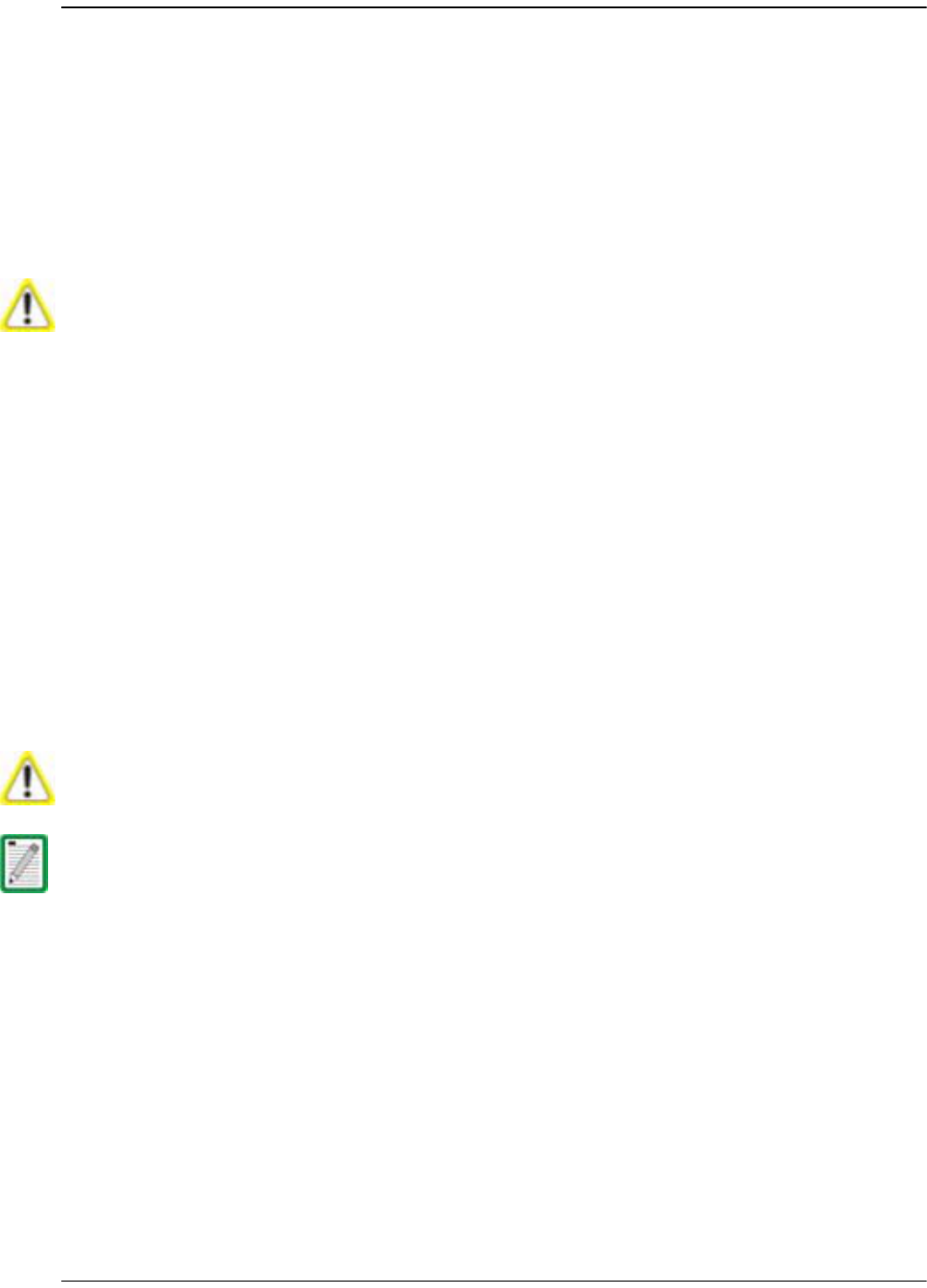
4.4.8 AC Power Wiring Installation
A 15-foot, 3-wire cable with connectors is provided for the AC power connections.
The connector end of the cable connects to the AC power port located on the bottom
of the unit. The stub end of the cable must be routed to an external junction box (not
provided) for permanent connection to the AC power system wiring.
The AC power source must supply between 100 and 240 VAC, 50 or 60 Hz,
single-phase power through a circuit breaker or fuse. The AC power cable provides
three wire leads for line, neutral, and ground connections. The power cable is rated
for indoor or outdoor use and must not be placed within electrical conduit as this will
impede the cooling of the cable during usage. The electrical junction box and any
conduit, wire, and fittings required must be provided by the installer.
The antenna cable connections must be weather proofed (sealed) for outdoor
installations.
Use extreme caution when working with high voltage AC power. Ensure all power is
disconnected before working on power circuits.
All electrical work must comply with local codes and requirements. A locally licensed
electrical contractor is best qualified to perform this work. For additional information,
consult with the ADC Technical Assistance Center (see “Contacting ADC” on page 335).
Installing the Remote Unit
Page 126 FlexWave Prism Host, Remote and EMS 5.1 System Reference
© 2009 ADC Telecommunications, Inc ADCP-77-073 • Issue 2 • 11/2009
Use the following procedure to install the AC power wiring:
355 Locate the AC power cable that is provided separately with the Remote.
366 Route the power cable between the AC power port, located on the underside of
the Remote and the nearest AC power junction box as shown below. It may be
necessary to install a new junction box if an existing junction box is not available.
377 Secure the cable between the AC power port and the AC power junction box per
local practice. Leave sufficient slack in the cable to allow it to be easily connected
and disconnected from the AC power port.
388 Install any AC power supply wires that may be required between the AC junction
box and the AC circuit breaker box.
The power cable is rated for indoor or outdoor use and must not be placed within
electrical conduit as this will impede the cooling of the cable during usage. The cable
run distance to the AC power source must not exceed 100 feet.
It is recommended that an AC outlet be installed near the Remote for powering tools
and test equipment. This outlet must include a GFCI device for protection.
An appropriate disconnect device, as well as branch circuit protection, must be provided
as part of the installation.
Remote enclosure
77073-071
AC power junction box
AC power cable
AC power wires routed
to circuit breaker panel
Install any 40W RF Module(s)
FlexWave Prism Host, Remote and EMS 5.1 System Reference Page 127
ADCP-77-073 • Issue 2 • 11/2009 © 2009 ADC Telecommunications, Inc.
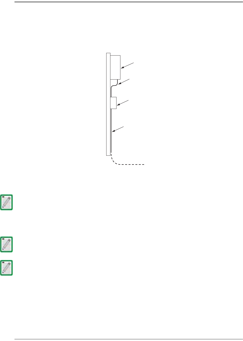
399 Connect the AC power cable wires to the AC power supply wires. Refer to the
following graphic to identify the color code and wire designations.
400 At the AC box, connect the AC power supply load wires to a circuit breaker or fuse.
411 Connect the ground wire to an approved earth ground.
422 Place the circuit breaker in the ON position and then test the connector end of the
AC power cable for proper voltage levels and correct polarity.
433 When testing is complete, place the circuit breaker in the OFF position.
For proper and safe equipment operation, an approved earth ground connection must
be provided and maintained.
AC power cord
provided with Remote Black
Green/Yellow
White
Line
Ground
Neutral
120 VAC power
wiring
120 VAC CONNECTIONS
Black
Green/Yellow
White
Line 1
Ground
Line 2
240 VAC power
wiring
240 VAC CONNECTIONS
77073-072
Connector Pin Designations
Pin 1 - Green/Yellow
Pin 2 - White
Pin 3 - Black
End view of
connector
12
3
AC power cord
provided with Remote
Installing the Remote Unit
Page 128 FlexWave Prism Host, Remote and EMS 5.1 System Reference
© 2009 ADC Telecommunications, Inc ADCP-77-073 • Issue 2 • 11/2009
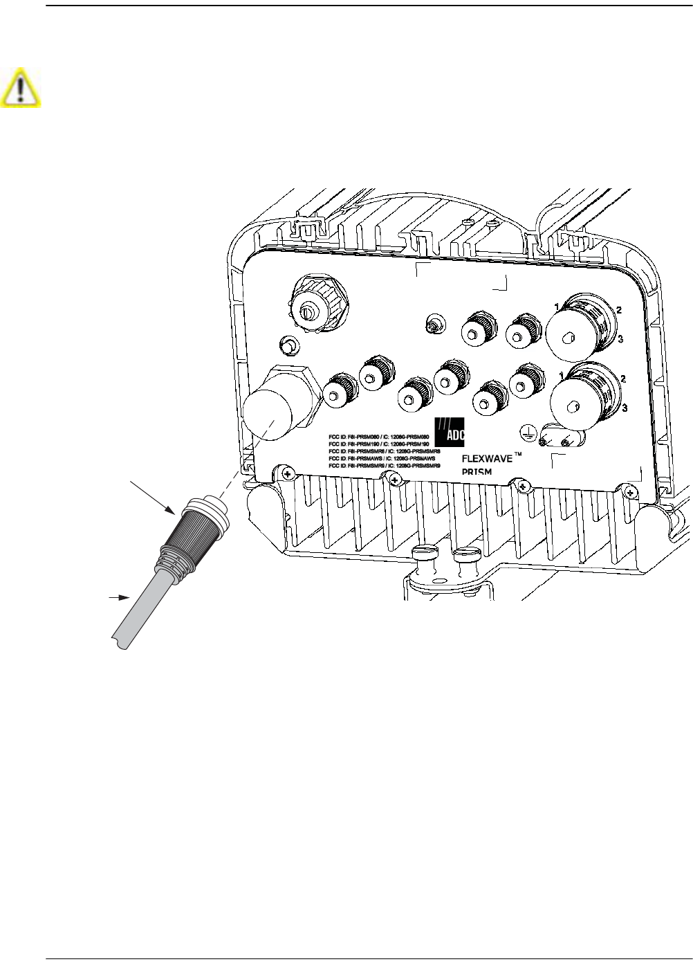
444 Remove the dust cap from the AC power port located on the bottom of the Remote
as shown below.
455 Connect the power cable connector to the AC power port.
466 Tighten coupling nut until the green band at the top of the connector body is
visible.
While trying to connect the AC power cable to the Remote AC power port, it is possible
for the line terminal on the cable connector to contact the ground pin on the power port.
If the AC cable is energized, this will result in a direct short to ground for the AC power.
To avoid possible personal injury and equipment damage, always turn the AC power off
before connecting the AC power cable to the AC power port.
NETWORK
AUX.
MOD A
RX1
MOD A
TX0/RX0
FIBER 1
FIBER 2
MOD B
TX0/RX0
MOD B
RX1
MOD C
TX0/RX0
MOD D
TX0/RX0
MOD C
RX1
MOD D
RX1
POWER
100-240 VAC
50-60 Hz
16 AMPS
77073-015
Bottom View
Power
cable
Green band will be
visible when coupling —
Nut is tightened
Install any 40W RF Module(s)
FlexWave Prism Host, Remote and EMS 5.1 System Reference Page 129
ADCP-77-073 • Issue 2 • 11/2009 © 2009 ADC Telecommunications, Inc.
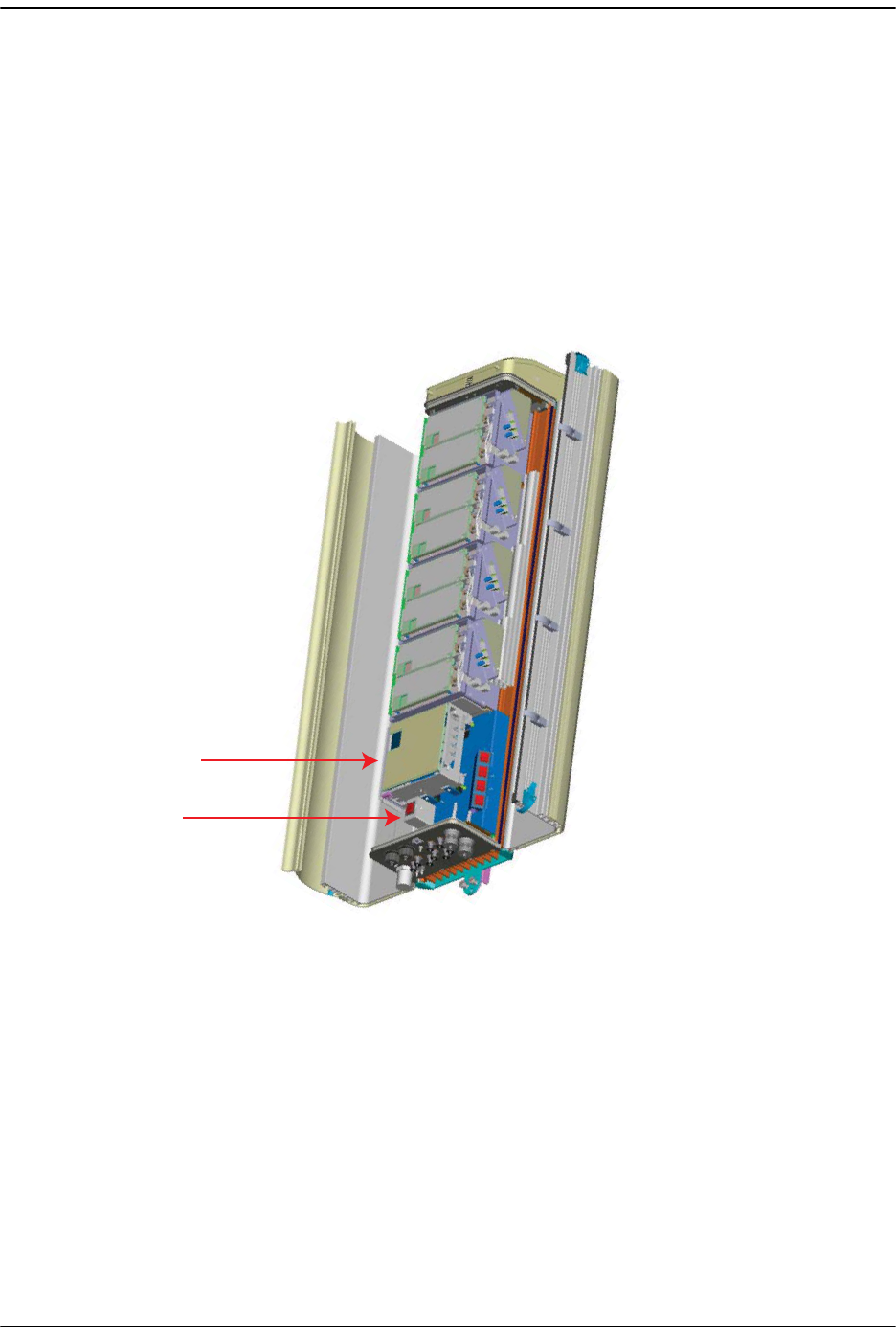
4.4.9 Determine the Circuit Breaker or Fuse for Remote
The Prism Remote supports power input from a 90 to 240 VAC power supply as
shown below.
4.4.9.1 Power Consumption
Do the following to determine the maximum power consumption, which determines
the circuit breaker or fuse to use.
477 Review the Remote order to determine the information listed below and then use
this information to find the power consumption from Table 4-2 and Table 4-3:
• RF bandwidth?
• DART type (Classic, Single SuperDART or Dual
SuperDART)
• Diversity or Non-Diversity?
Power module
AC switch
DC switches (4)

Installing the Remote Unit
Page 130 FlexWave Prism Host, Remote and EMS 5.1 System Reference
© 2009 ADC Telecommunications, Inc ADCP-77-073 • Issue 2 • 11/2009
488 Enter the power consumption in the spaces provided below.
499 For the total RF Module power consumption, calculate the power consumption
from Table 4-3 on page 131 for each RF Module present in the Remote (RF Module
A - D), add the Watts, and then enter the total in the Total Power Consumption
field.
500 Divide the total Watts by the input Voltage to determine the current (Amperes)
requirements.
511 Determine the circuit breaker or fuse size based on local codes and practices.
Circuit breaker or fuse size must be 20 Amps or less.
SeRF Module power consumption from Table 4-2 _________Watts
Additional SFPs _____ x 1.25W _________Watts
RF Module A power consumption from Table 4-3 _________Watts
RF Module B power consumption from Table 4-3 _________Watts
RF Module C power consumption from Table 4-3 _________Watts
RF Module D power consumption from Table 4-3 _________Watts
TOTAL POWER CONSUMPTION _________Watts
Watts
= Amps
Volts

Install any 40W RF Module(s)
FlexWave Prism Host, Remote and EMS 5.1 System Reference Page 131
ADCP-77-073 • Issue 2 • 11/2009 © 2009 ADC Telecommunications, Inc.
4.4.9.2 Power Consumption Tables
Table 4-2. SeRF Module Power Consumption
SeRF Module
Power Consumption per Module
Nominal (W) @ 25C Maximum (W)
SeRF Module (1 SFP)
[add 1.25W for each SFP
added]
36 38
Table 4-3. RF Module Power Consumption
Prism RF Module Description
Power Consumption per Module
Nominal (W)@
25C Maximum (W)
Single or Dual
SuperDART
RF Module
10W GSM900 Non-Diversity 299 337
Diversity 321 359
15.8W GSM1800 Non-Diversity 299 337
15.8W UMTS Non-Diversity 285 350
20W PCS or 20W AWS Non-Diversity 299 368
Classic DART
RF Module
20W PCS or 20W AWS Non-Diversity 292 358
Diversity 314 381
6.5W CELL or
6.5W ESMR
Non-Diversity 195 196
Diversity 218 220
20W CELL Non-Diversity 271 327
Diversity 293 350
Installing the Remote Unit
Page 132 FlexWave Prism Host, Remote and EMS 5.1 System Reference
© 2009 ADC Telecommunications, Inc ADCP-77-073 • Issue 2 • 11/2009
4.4.10 Mount the Remote and Power Up
522 Refer to the detailed instructions for mounting the FlexWave Prism Remote in the
Remote Unit Mounting Kit Installation Instructions (ADCP-77-077) to mount the
Remote in the location selected in Section 4.2, Remote Mounting Plans, on page
96.
533 Power up the Remote by turning its AC power switch to On.
544 Close and tightly secure the Remote door and Solar Shield.
SeRF
Module
AC Power
switch for
Remote
chassis
77073-049

FlexWave Prism Host, Remote and EMS 5.1 System Reference Page 133
ADCP-77-073 • Issue 2 • 11/2009 © 2009 ADC Telecommunications, Inc.
PART III
SYSTEM SETUP AND MANAGEMENT

Page 134 FlexWave Prism Host, Remote and EMS 5.1 System Reference
© 2009 ADC Telecommunications, Inc ADCP-77-073 • Issue 2 • 11/2009
Intentionally Blank Page

FlexWave Prism Host, Remote and EMS 5.1 System Reference Page 135
ADCP-77-073 • Issue 2 • 11/2009 ©2009 ADC Telecommunications, Inc.
5FLEXWAVE ELEMENT MANAGEMENT SYSTEM
5.1 FlexWave EMS Overview ...................................................................................136
5.2 EMS Graphical User Interface.............................................................................138
5.3 Product Identity ...............................................................................................139
5.4 EMS Menu Bar .................................................................................................140
5.5 EMS Alarm Indications ......................................................................................141
5.6 EMS System Requirements ................................................................................142
This chapter introduces the ADC FlexWave Prism Element Management System (EMS).
Content Page
FlexWave Element Management System
Page 136 FlexWave Prism Host, Remote and EMS 5.1 System Reference
© 2009 ADC Telecommunications, Inc ADCP-77-073 • Issue 2 • 11/2009
5.1 FLEXWAVE EMS OVERVIEW
The ADC FlexWave EMS is an embedded software application that is accessed through
an internet connection using a Web browser and provides a Graphical User Interface
(GUI) for control and monitoring of a Prism system.
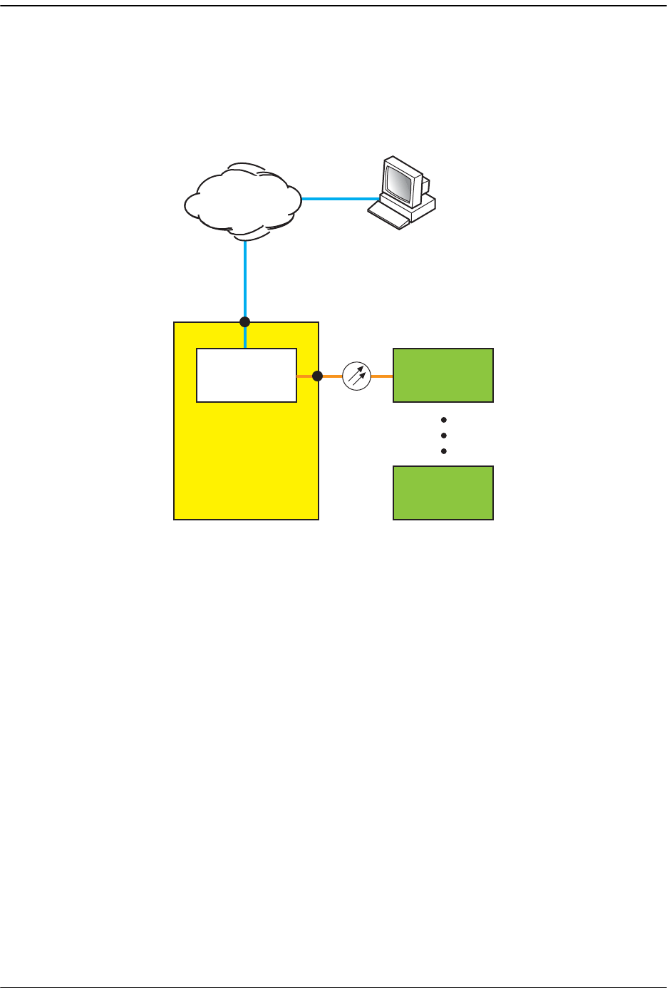
Figure 5-1. Typical FlexWave Prism System
EMS
IP
IP
Windows 2000 or Windows XP
computer running
Internet Explorer 6.0
WEB
REMOTE
REMOTE
77073-020
HOST
UP TO 8
FlexWave EMS Overview
FlexWave Prism Host, Remote and EMS 5.1 System Reference Page 137
ADCP-77-073 • Issue 2 • 11/2009 © 2009 ADC Telecommunications, Inc.
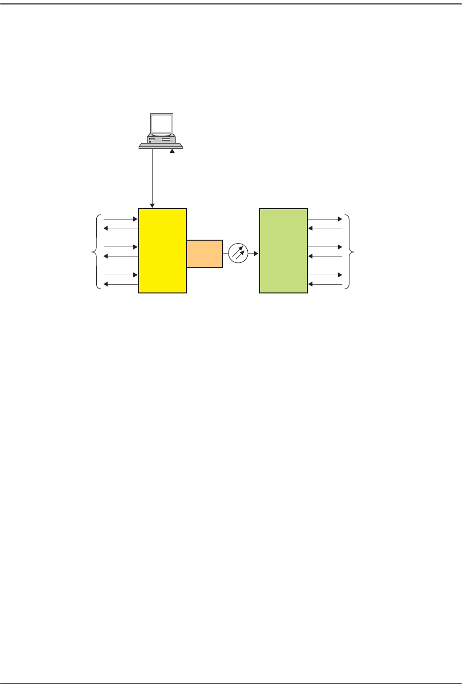
As shown in Figure 5-2, you access the embedded EMS through the Host, where RF
signals are converted to optical signals for distribution to the local coverage area. The
EMS is thus in a position to monitor both types of signals, and to report status,
alarms, and RF signal levels through automatic, periodic updates and in response to
user requests. User requests can include commands to set RF gain and propagation
delay.
Figure 5-2. The Function of the EMS
HOST
with
Embedded
Element
Management
System
FlexWave
REMOTE
BTSs Antennas
RFRF
OPTICAL
WDM
(Optional)
User
Requests
Status
Alarms
RF Signal Levels
77073-021
FlexWave Element Management System
Page 138 FlexWave Prism Host, Remote and EMS 5.1 System Reference
© 2009 ADC Telecommunications, Inc ADCP-77-073 • Issue 2 • 11/2009
5.2 EMS GRAPHICAL USER INTERFACE
Before you start using the EMS, familiarize yourself with its components.
You use a Web browser to access the EMS Graphical User Interface (GUI). A typical
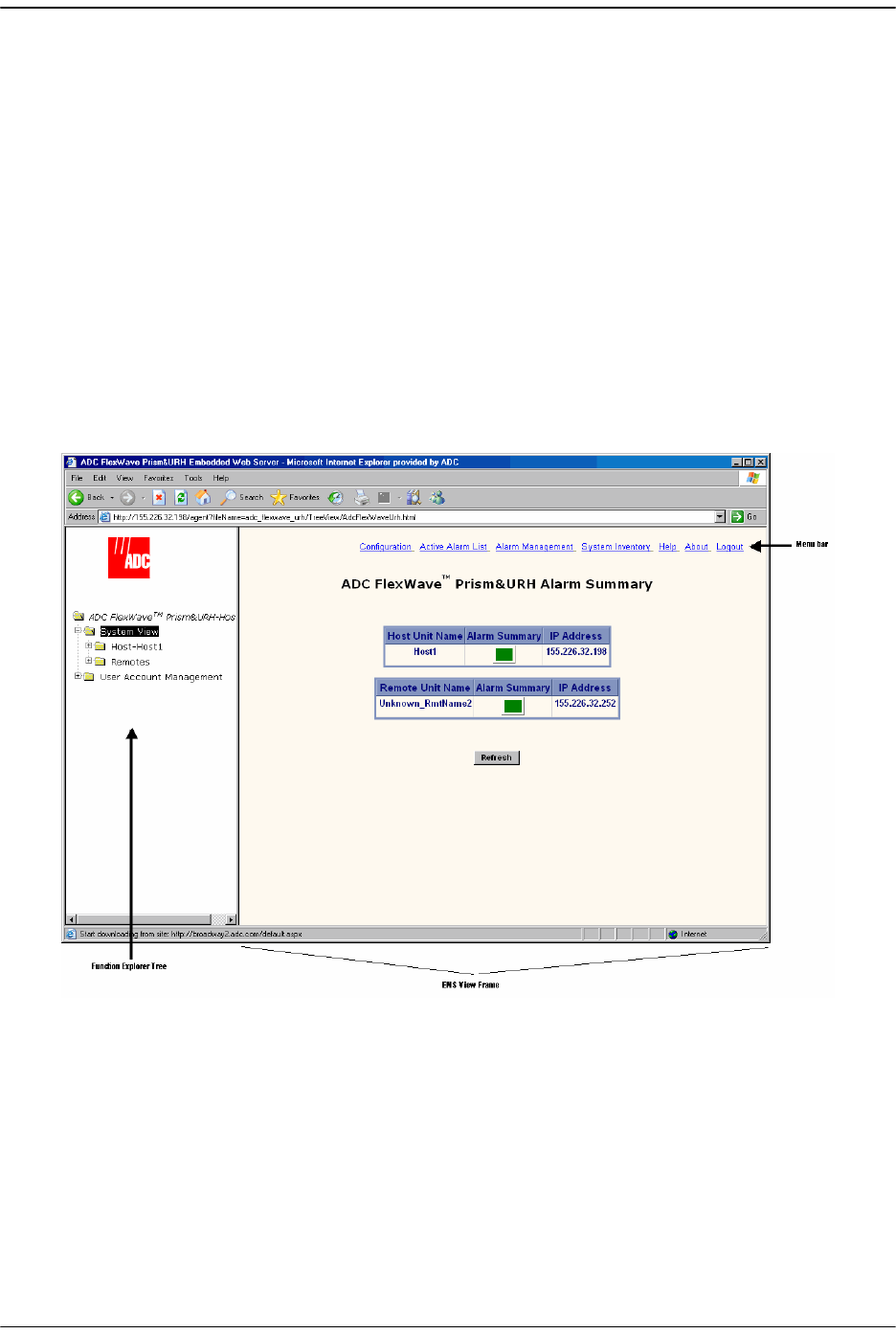
display consists of the two frames shown in Figure 5-3.
•• Function Explorer Tree—appears in the left frame. Click on a node to open the
corresponding screen.
•• EMS View Frame—appears in the right frame. A typical page contains alarm
indicators, lists of parameter values, and tools such as lists and text boxes that
allow you to set parameter values.
The EMS View Frame includes the EMS Menu bar, which provides access to EMS
configuration or summary windows. For further information on the EMS Menu
bar, see “EMS Menu Bar” on page 140.
Figure 5-3. EMS Screen Example

Product Identity
FlexWave Prism Host, Remote and EMS 5.1 System Reference Page 139
ADCP-77-073 • Issue 2 • 11/2009 © 2009 ADC Telecommunications, Inc.
5.3 PRODUCT IDENTITY
The FlexWave Prism system comprises a mix of URH Hosts and Prism Remotes. The
system components are therefore identified as follows in the EMS:
•• Login screens—
ADC FlexWave
™
Prism&URH
•• Summary views—
ADC FlexWave
™
Prism&URH
•• Host views—
ADC FlexWave
™
Prism&URH on Host
•• Remote views refer to the Remote type:
–A
ADC FlexWave
™
Prism Remote Unit
–A
ADC FlexWave
™
URH Remote Unit
FlexWave Element Management System
Page 140 FlexWave Prism Host, Remote and EMS 5.1 System Reference
© 2009 ADC Telecommunications, Inc ADCP-77-073 • Issue 2 • 11/2009
5.4 EMS MENU BAR
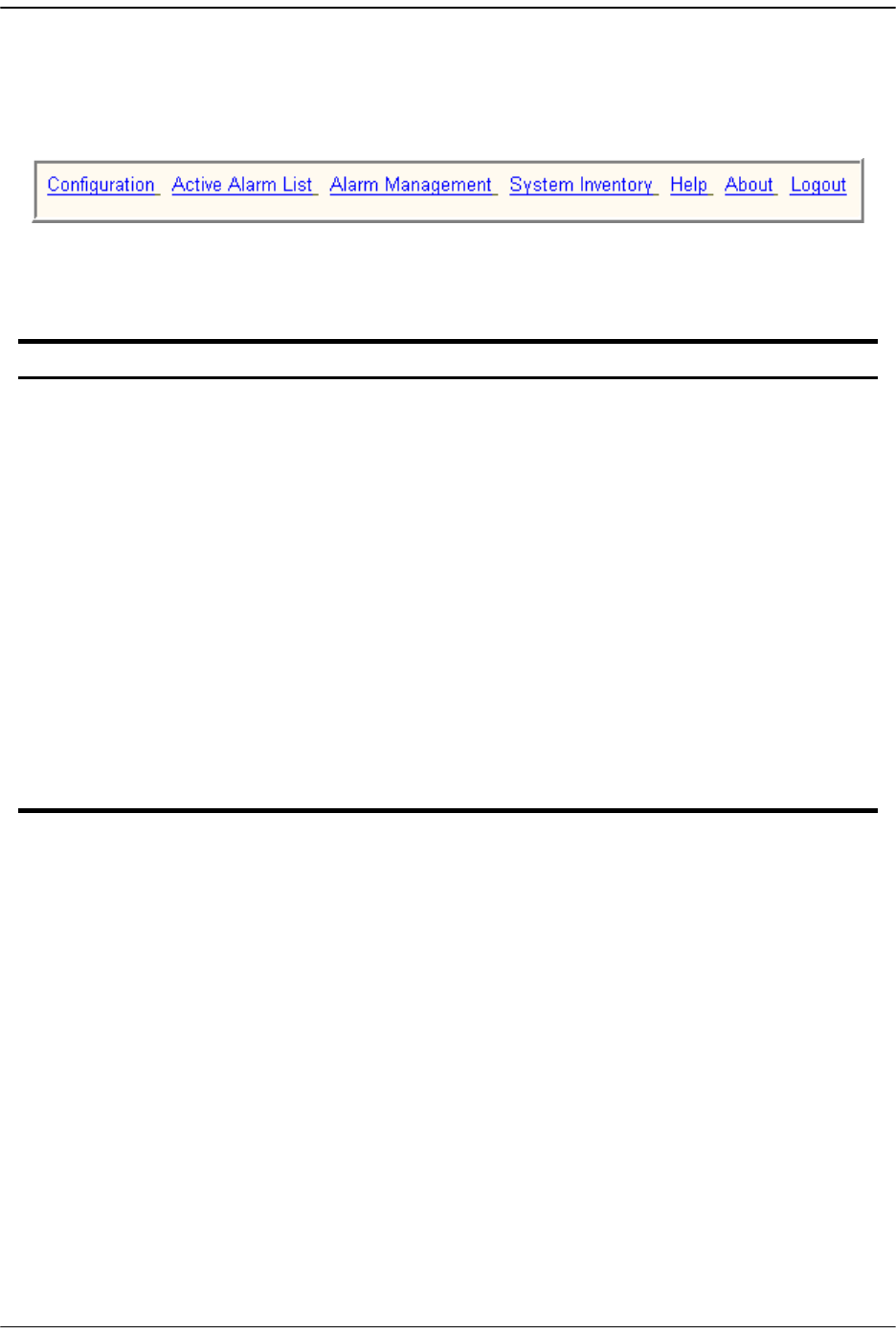
The EMS Menu bar links (Figure 5-4) perform as described in Table 5-1.
Figure 5-4. EMS Menu Bar
Table 5-1. EMS Menu Bar Links
Link Function
Configuration
Opens the General Configuration window from which you set system Auto
refresh. See “Setting Auto Refresh” on page 179.
Active Alarm List
Opens the Active Alarm List window, which is a means to determine alarm
type, Host unit name, Remote name, time stamp, and other information for
active alarms. See “Viewing Active Alarms” on page 258. The Active Alarm
List window provides a link to the History Log (see “Viewing an Alarm History
Log” on page 259).
Alarm
Management
Opens the Alarm Management Table, from which you can mask and unmask
alarms. See “Masking an Alarm Type” on page 260 or “Unmasking an Alarm
Type” on page 262.
System
Inventory
Opens the System Inventory view, which identifies the main software and
hardware components of the current, working system. See “Working with the
System Inventory” on page 180.
Help
Opens the EMS online help system that provides a description for each node
in the Function Explorer Tree. To access a specific help topic, click on the
appropriate link. (The Help: Overview topic is the default topic.)
About
Opens a window that provides the software-release version of the EMS, and
copyright and trademark information.
Logout
Logs you out of the EMS.
EMS Alarm Indications
FlexWave Prism Host, Remote and EMS 5.1 System Reference Page 141
ADCP-77-073 • Issue 2 • 11/2009 © 2009 ADC Telecommunications, Inc.
5.5 EMS ALARM INDICATIONS
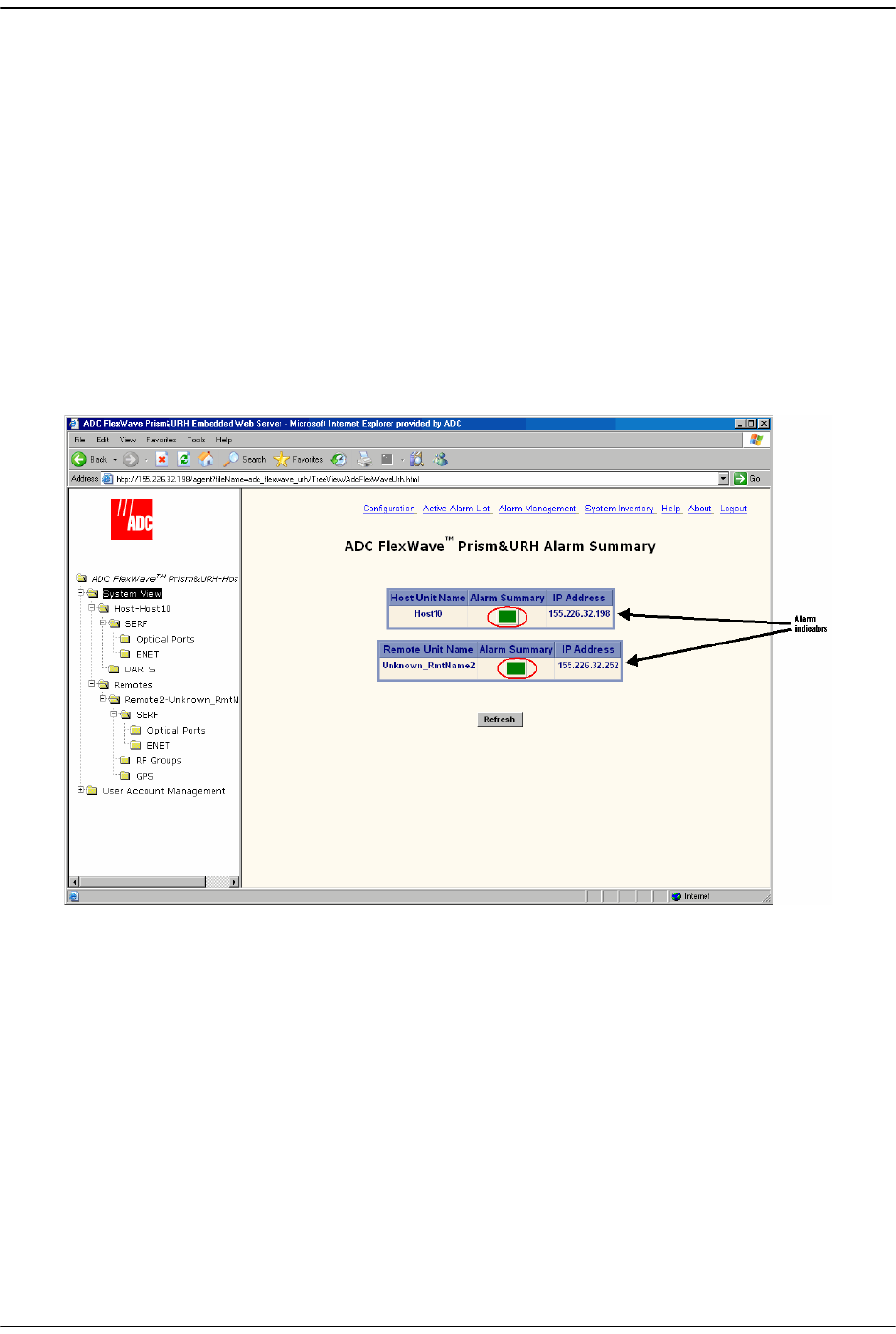
Some EMS parameter values are associated with alarms. When a parameter enters an
alarm state, an alarm status indicator is activated where the color of the indicates the
alarm severity (Figure 5-5):
•• Red status indicator—major alarm
•• Yellow status indicator—minor alarm
•• Green status indicator—normal (okay) state
•• White status indicator—a device or component is not communicating, but is in the
EMS database
•• Grey status indicator—alarm is masked.
Figure 5-5. Example of Alarm Indicators
For further information on EMS alarms, see “Managing Alarms” on page 257.

FlexWave Element Management System
Page 142 FlexWave Prism Host, Remote and EMS 5.1 System Reference
© 2009 ADC Telecommunications, Inc ADCP-77-073 • Issue 2 • 11/2009
5.6 EMS SYSTEM REQUIREMENTS
The computer that you use to remotely access the EMS must meet the following
minimum requirements:
•• Windows 2000 or Windows XP operating system
•• Internet Explorer version 6.0. When a direct connection is made, an internet
connection is not needed, but the user interface still displays in a Web browser.
•• Network Interface Card (NIC)
•• Ethernet cable with RJ-45 connectors.
The EMS database can also be accessed remotely using an SNMP manager. In this case,
the user interface varies depending on the SNMP manager, but the underlying
parameters, parameter values, and alarms are the same as in the standard EMS
interface.

FlexWave Prism Host, Remote and EMS 5.1 System Reference Page 143
ADCP-77-073 • Issue 2 • 11/2009 ©2009 ADC Telecommunications, Inc.
6INITIAL PRISM SYSTEM SETUP
6.1 Access the EMS................................................................................................144
6.2 Discover IP Addresses.......................................................................................146
6.3 Enter a Host Name, Clock Source, and Linking Mode .............................................147
6.4 Set the Clock Priority Level ................................................................................150
6.5 Provision the Host SeRF Optical Ports..................................................................151
6.6 Configure the Host DARTs .................................................................................152
6.7 Enter a Remote Name.......................................................................................156
6.8 Configure the Remote SeRF Optical Ports.............................................................158
6.9 Link the Host and Remote DARTs. ......................................................................159
6.9.1 Use of Multi Fibers ....................................................................................159
6.9.2 RF Groups in the Remote and the EMS GUI ..................................................160
6.9.3 Link a Remote DART to a Host DART ...........................................................162
6.10 Conclude Initial System Setup..........................................................................167
6.11 (Optional) Configuring Multi-Host Systems for Manual Mode .................................168
6.11.1 Set the Multi-Host System to Manual Mode.................................................168
6.11.2 Configure the Host DARTs ........................................................................168
6.11.3 Configure the Remote DARTs....................................................................173
This chapter guides you through an initial Prism system setup, which requires that
you follow the steps in the order given. There are 42 steps in this process that are
divided into 10 sections.
Content Page
Only a user logged in under the admin account can complete the initial Prism setup
through the EMS.
Initial Prism System Setup
Page 144 FlexWave Prism Host, Remote and EMS 5.1 System Reference
© 2009 ADC Telecommunications, Inc ADCP-77-073 • Issue 2 • 11/2009
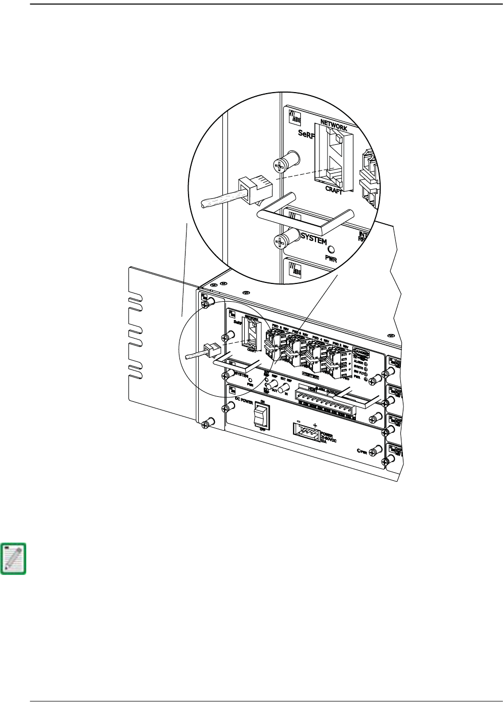
6.1 ACCESS THE EMS
11 Use an Ethernet CAT 5 cable with RJ-45 connectors to connect a laptop to the Craft
port of the Host, as shown in the following figure.
22 Connect your computer and start a Web browser.
33 In the Web browser URL field, enter the following IP address: 192.168.0.1
If you have configured your Prism system with static IP addresses, enter the assigned
IP address instead of 192.168.0.1.
77073-075
RJ-45
Connector
Detail

Access the EMS
FlexWave Prism Host, Remote and EMS 5.1 System Reference Page 145
ADCP-77-073 • Issue 2 • 11/2009 © 2009 ADC Telecommunications, Inc.
44 When the
ADC FlexWave Prism&URH Embedded Web Server Welcome
window opens:
aa In the
Username
box, type the user name provided by ADC or by the Network
Administrator. The default user name is admin.
bb In the
Password
box, type the password provided by ADC or by the Network
Administrator. The default password is adc123.
55 Click
Login
. to open the
Welcome to ADC FlexWave Prism Embedded Web Server
page.
Initial Prism System Setup
Page 146 FlexWave Prism Host, Remote and EMS 5.1 System Reference
© 2009 ADC Telecommunications, Inc ADCP-77-073 • Issue 2 • 11/2009
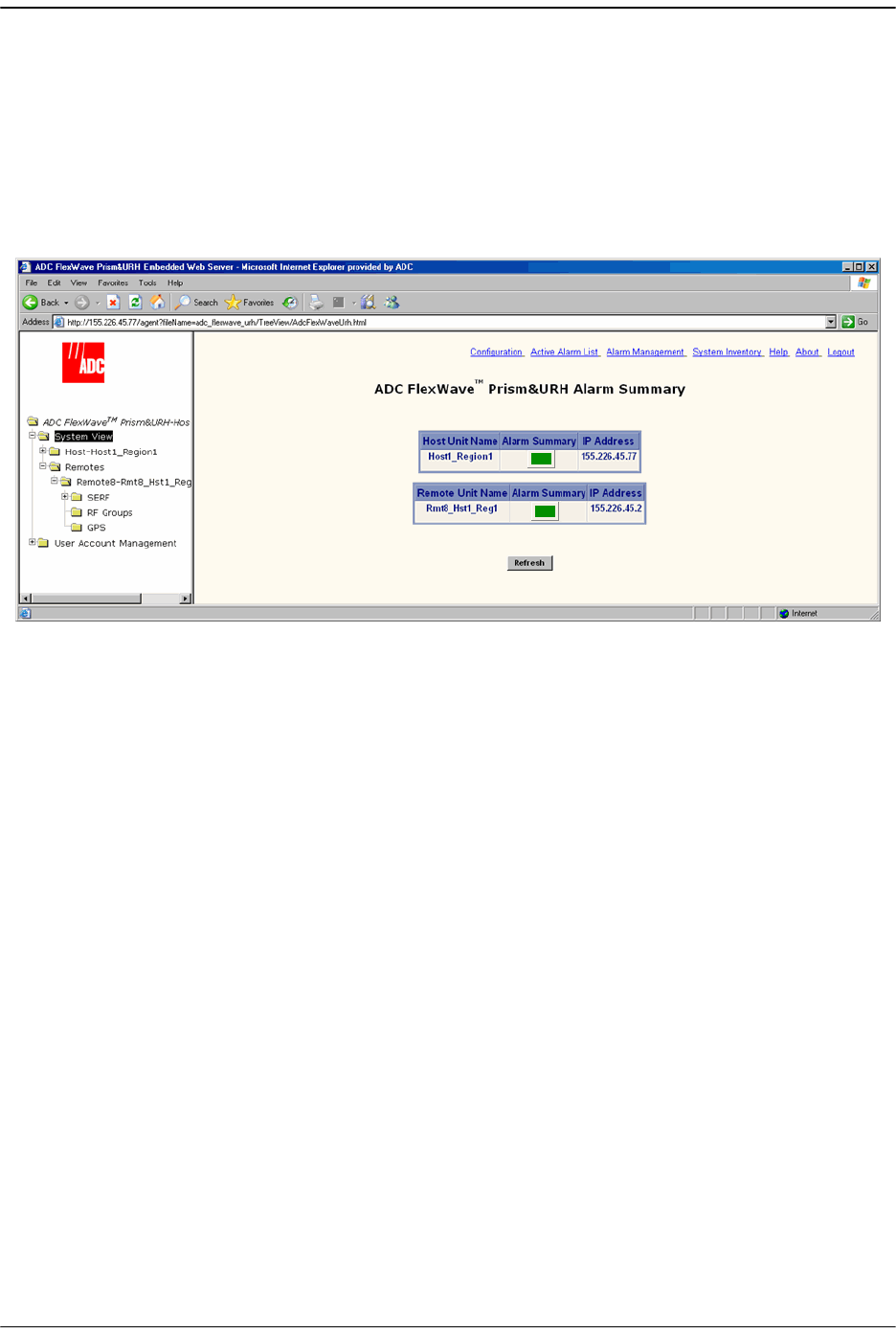
6.2 DISCOVER IP ADDRESSES
66 In the Function Explorer Tree, click on
System View
to display a system view.
The
Alarm Summary
view opens in the EMS View Frame. The
Alarm Summary IP
Address
columns provide the IP address for the Host and Remote. You can use this
IP address to log into the Host and Remote unit through a LAN or WAN
connection.
The
Alarm Summary
view will display all Remotes connected to the Host, so up to
eight Remotes can be listed. (The number of Remotes listed changes as Remotes
are added or removed from the FlexWave system.)
77 Note the Host IP address for future use: _________________________
88 Note the Remote IP address(es) for future use:
•• Remote1 _________________________
•• Remote2 _________________________
•• Remote3 _________________________
•• Remote4 _________________________
•• Remote5 _________________________
•• Remote6 _________________________
•• Remote7 _________________________
•• Remote8 _________________________
Enter a Host Name, Clock Source, and Linking Mode
FlexWave Prism Host, Remote and EMS 5.1 System Reference Page 147
ADCP-77-073 • Issue 2 • 11/2009 © 2009 ADC Telecommunications, Inc.
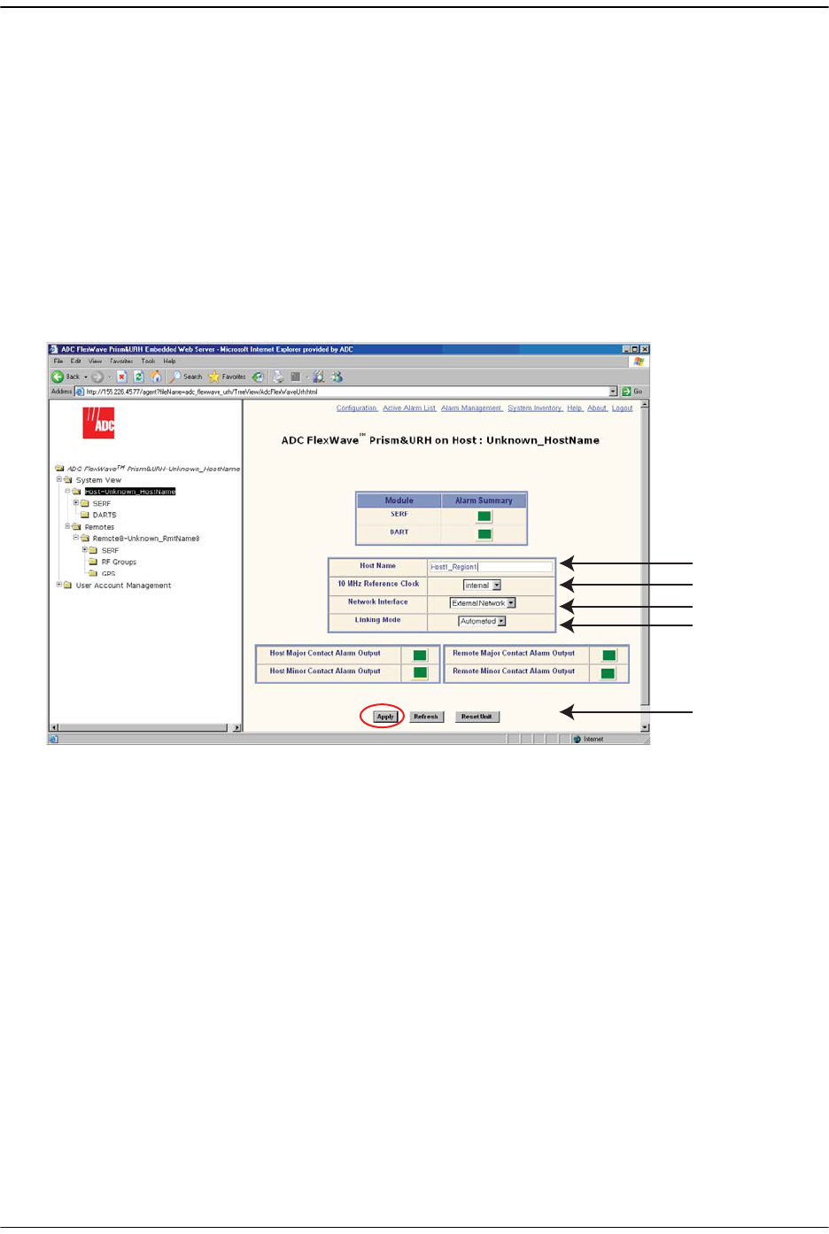
6.3 ENTER A HOST NAME, CLOCK SOURCE,AND LINKING
MODE
99 In the Function Explorer Tree, select
System View
,
Host-Unknown_HostName
to open
the
Host Summary
view in the EMS View Frame. (For information on the read-only
status indicators in the
Host Summary
view, see “Viewing the Host Summary” on
page 214.)
100 In the
Host Name
box, enter an identifying name for the Host. The
Host Name
must
be between 5 and 40 characters, with no spaces. The only special character
allowed is an underscore, but it cannot be the first character of the name.
Numerals are allowed, but cannot be the first character of the name.
10
12
13
14
11 and again at 15
Initial Prism System Setup
Page 148 FlexWave Prism Host, Remote and EMS 5.1 System Reference
© 2009 ADC Telecommunications, Inc ADCP-77-073 • Issue 2 • 11/2009
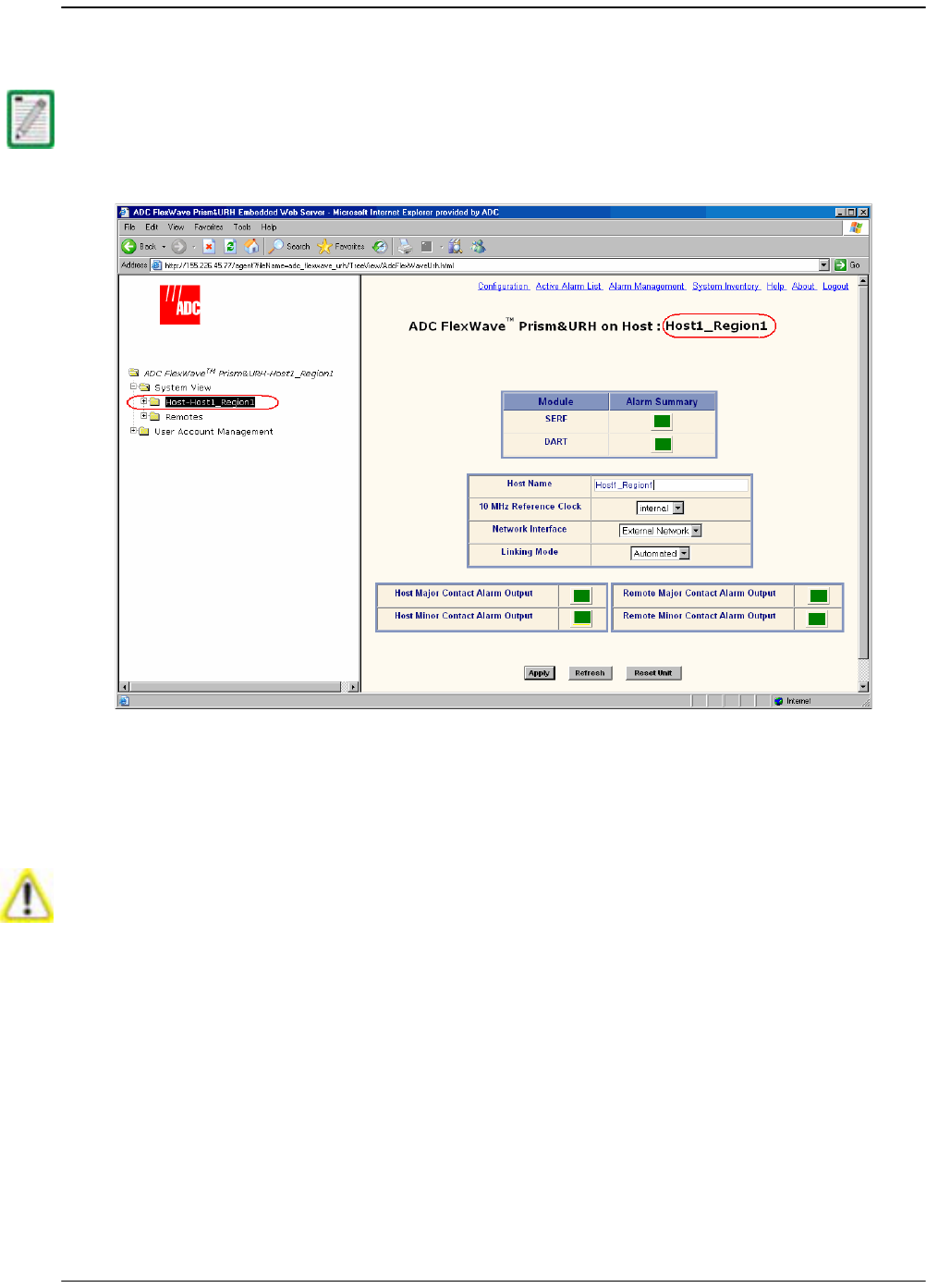
111 Click
Apply
. The new
Host Name
displays in the Function Explorer Tree and the
Host
Summary
view as part of the view title and in the
Host Name
box.
122 In the
10 MHz Reference Clock
list, select
internal
(default) or
external
. The SeRF
board on each Host and Remote contains the master clock for that unit. At the
Remote, the reference is a clock derived from the Host clock. The
10 MHz Reference
Clock external
setting allows you to frequency lock the master clock to an external
10 MHz reference.
You may need to click in the Function Explorer Tree frame and then click Refresh before
the new name appears.
When using the 10 MHz external reference clock, the signal must be connected to the
Host before enabling the clock in the software. If an external 10MHz reference clock is
selected for operation, but is not present or outside of the frequency range of 10MHz
+ /- 5ppm, communication between the Host and Remote over the optical fiber will fail.

Enter a Host Name, Clock Source, and Linking Mode
FlexWave Prism Host, Remote and EMS 5.1 System Reference Page 149
ADCP-77-073 • Issue 2 • 11/2009 © 2009 ADC Telecommunications, Inc.
133 Skip setting the
Network Interface
parameter—do not change this setting during
this procedure. Refer to “Changing to Built-In Network Mode” on page 186 for
information on setting the
Network Interface
.
144 In the
Linking Mode
list, keep the default setting of
Automated.
In Automated
Linking mode, the Host passes its
DART Pass Band
and
DART Diversity Status
to
connected Remotes. For a Multi-Host system, you must select
Manual
as this allows
you to manually set
DART Pass Band
and
DART Diversity Status
. If you are setting up
a Multi-Host system, leave the
Linking Mode
set to
Automated
, complete the initial
setup, and then complete “(Optional) Configuring Multi-Host Systems for Manual
Mode” on page 168.
155 Click
Apply
to save the
10 MHz Reference Clock
and
Linking Mode
changes.
Initial Prism System Setup
Page 150 FlexWave Prism Host, Remote and EMS 5.1 System Reference
© 2009 ADC Telecommunications, Inc ADCP-77-073 • Issue 2 • 11/2009
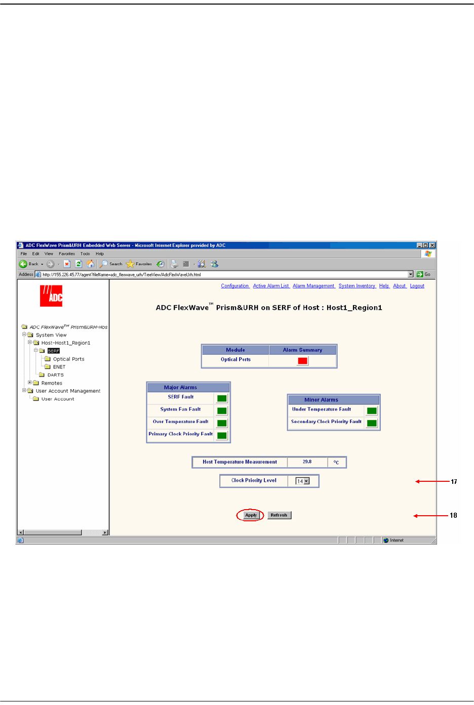
6.4 SET THE CLOCK PRIORITY LEVEL
166 In the Function Explorer Tree, select
System View
,
Host-
x,
SERF
(where
-
x is the Host
name) to open the
Prism on SERF of Host
-n view in the EMS View Frame.
177 In the
Clock Priority Level
list, set the Clock Priority Level for the Host. This is in
effect a Master/Slave setting in that the Host in a multi-Host system with the
highest
Clock Priority Level
(CPL) will provide the Master Clock on the fibers. All
other Hosts and Remotes will recover clocks from higher levels. The highest level
is
1
, the lowest level is
14
.
0
and
15
are “no level” settings that results in a zero
pattern being played on the fiber, which effectively shuts it down. The default is
14
.
In a Multi-Host system, each Host must have a unique CPL. If one or more Host is
set to the same CPL, an alarm will be generated.
188 Click
Apply
.
For information on the SeRF alarm indicators, see “Viewing the Host SeRF
Summary” on page 222.
Provision the Host SeRF Optical Ports
FlexWave Prism Host, Remote and EMS 5.1 System Reference Page 151
ADCP-77-073 • Issue 2 • 11/2009 © 2009 ADC Telecommunications, Inc.
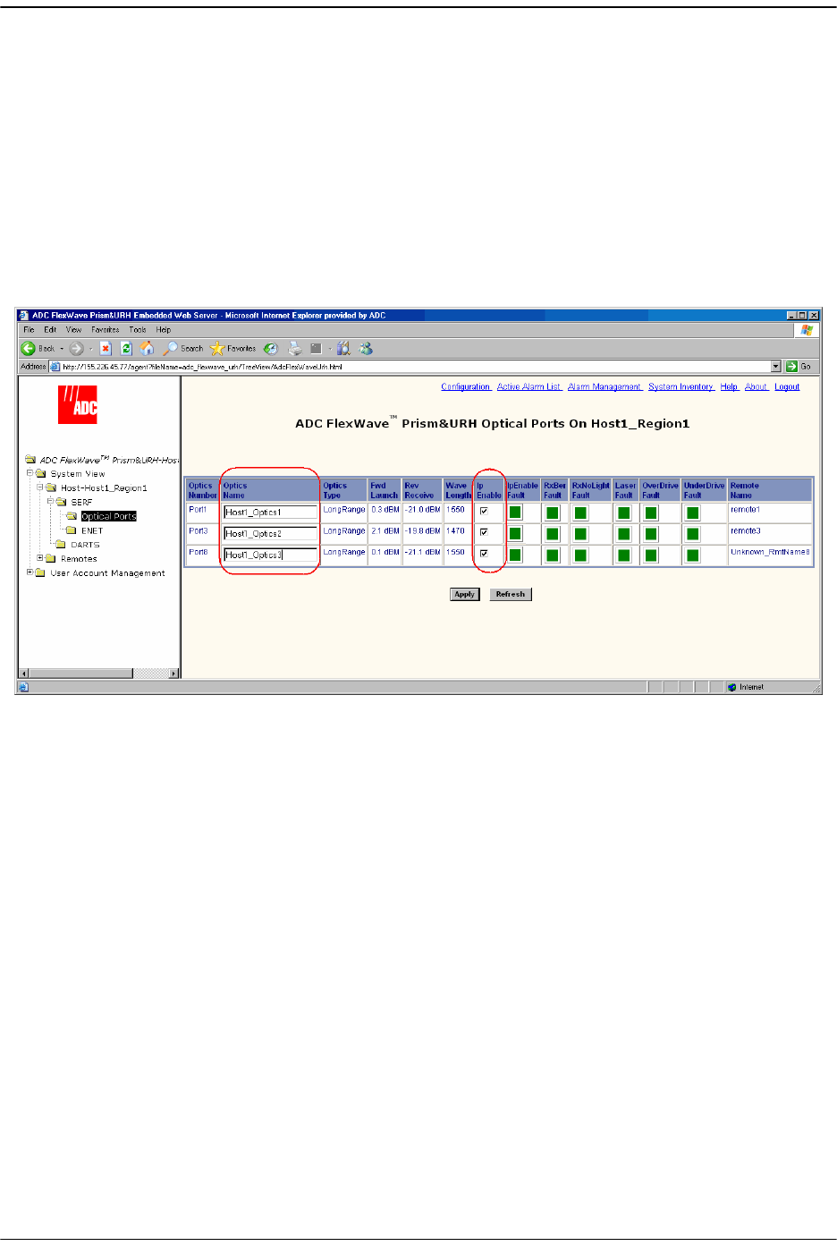
6.5 PROVISION THE HOST SERF OPTICAL PORTS
There can be up to eight Host SeRF optical ports that correspond to the eight physical
ports on the Host. Labeling the Host SeRF Optical Ports provides for easier off-site
management.
199 In the Function Explorer Tree, select
System View
,
Host-
x,
SERF
,
Optical Ports
(where
-
x is the Host name) to open the
Optical Ports
view for the Host in the EMS View
Frame. The default
Optics Name
for the Optical ports is
UNKNOWN_SFPNAME
. (For
information on the status indicators in the
Optical Ports
view, see “Viewing Host
SeRF Optical Ports” on page 224.)
200 In the
Optics Name
box, enter a label for the selected Optics port. The
Optics Name
must be between 5 and 32 characters with no spaces. The only special character
allowed is an underscore, but it cannot be the first character of the name.
Numerals are allowed, but cannot be the first character of the name.
211 Select
Ip Enable
to configure the Small Form-Factor Pluggable (SFP) for exchange of
management traffic. By default
Ip Enable
is not selected. If
Ip Enable
is left
unselected, the SFP cannot exchange management traffic. How you set
Ip Enable
is
dependent on the system configuration:
•• In a multifiber scenario, do not enable IP on both SFPs from the same Host to
the same Remote. Typically, the first SFP on the Host that goes to that Remote
is used as the IP enabled port for management communications.
•• In a Multi-Host system, multiple fibers connected to a Remote come from
different Hosts. However, a Remote can accept an IP connection from only one
Host and only one Host can “own” the Remote for the purposes of provisioning
and monitoring. When a second Host attempts to establish an IP connection,
this second connection fails and an IP Conflict alarm is triggered. You
therefore select
Ip Enable
only for the Host that manages the Remote so that
only one of the fibers connected to the Remote will have IP.
222 Click
Apply
.
Initial Prism System Setup
Page 152 FlexWave Prism Host, Remote and EMS 5.1 System Reference
© 2009 ADC Telecommunications, Inc ADCP-77-073 • Issue 2 • 11/2009
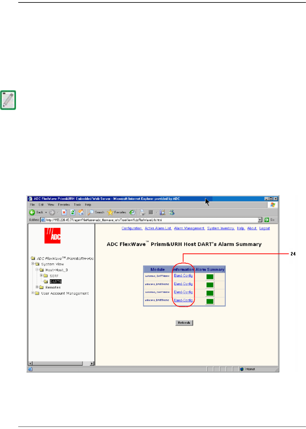
6.6 CONFIGURE THE HOST DARTS
Configuring a Host DART provides information required for the DART to operate in
RF transmission. Each DART is configured in hardware to operate within a specific RF
band such as PCS or Cellular; the passband is a software-defined sub-band of the
hardware-defined band. Forward and reverse path gain, diversity status, and
operating mode may also be set when a Host DART is configured. The same settings
are applied to the Remote DART when linked to the Host DART. The Host has eight
slots for DART cards.
233 In the Function Explorer Tree, select
System View
,
Host-
x,
SERF
,
DARTS
(where
-
x is
the Host name) to open the
DART’s Alarm Summary
view in the EMS View Frame.
The
DART’s Alarm Summary
view displays all the Host DARTS that are present,
starting from slot 1 at the top of the list and working sequentially down to last
DART, which can be slots 1-8.
244 In the
Information
column, click on the
Band-Config
link for the DART to be
configured.
If you are setting up a multi- host system, go to “(Optional) Configuring Multi-Host
Systems for Manual Mode” on page 168.
Configure the Host DARTs
FlexWave Prism Host, Remote and EMS 5.1 System Reference Page 153
ADCP-77-073 • Issue 2 • 11/2009 © 2009 ADC Telecommunications, Inc.
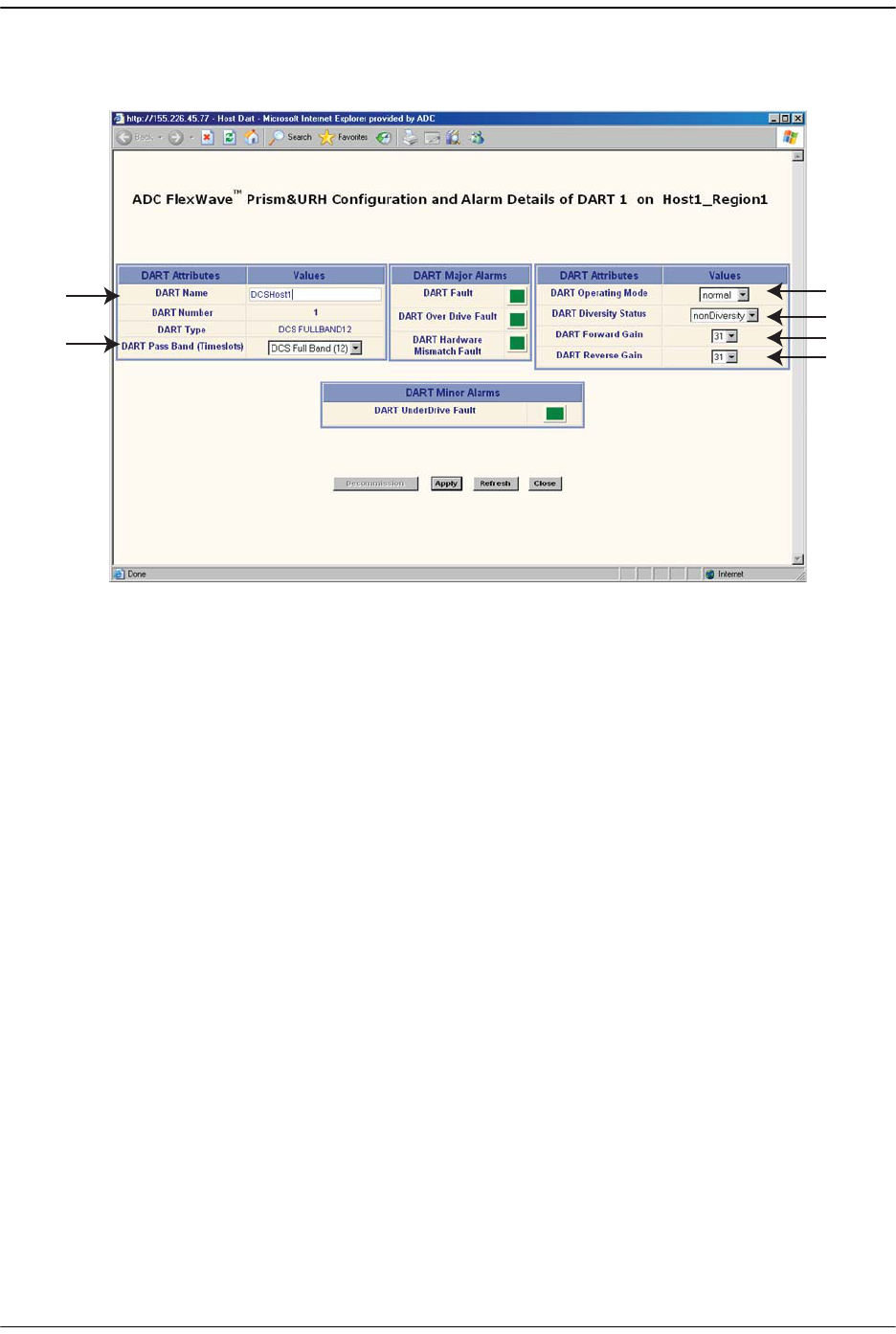
255 In the
Configuration and Alarm Details of DART n
window that opens, set the
DART
Attributes
:
aa In the
DART Name
box, enter a name for the DART between 5 and 32 characters
with no spaces. The only special character allowed is an underscore, but it
cannot be the first character of the name. Numerals are allowed, but cannot be
the first character of the name.
bb In the
DART Pass Band (Timeslots)
list, select the DART Pass Band to be
supported by this DART. The list will include only those pass bands that are
valid selections for the DART band. For example, if the DART band is
“cellular,” only cell pass bands are listed.
cc In the
DART Operating Mode
list, select one of the following:
•
Standby
—forces the RF function to be muted in the Host and its linked
Remote.
•
Normal
—allows the system to operate normally (RF function not forced to
be muted), assuming all other system components are in proper working
order. (Default setting.)
The mode
Undefined
is not user selectable, and indicates that the EMS is
unaware of the current mode.
dd In the
DART Diversity Status
list, select
nonDiversity
or
diversity
. For a diversity
application, one DART will be configured
nonDiversity
for the primary
FWD/REV path signal and the other DART will be configured
Diversity
. This
selection therefore determines whether the DART card being configured will
carry the primary or secondary RF path.
a
b
c
d
e
f
Initial Prism System Setup
Page 154 FlexWave Prism Host, Remote and EMS 5.1 System Reference
© 2009 ADC Telecommunications, Inc ADCP-77-073 • Issue 2 • 11/2009
For dual DART configurations, such as dual-pcs, smr800/smr900 and
dual-aws, both DARTs must have
DART Diversity Status
set to
nonDiversity
.
ee In the
DART Forward Gain
list, set this value (0 to 31 dB) based upon the fully
loaded forward path signal level from the Base Station. The Host DART expects
signal levels from
-25
to
+5 dBm
. If the fully loaded signal is +5 dBm, then the
DART forward gain should be set to 0 dB, if the fully loaded signal is -25 dBm,
then the DART Forward Gain should be set to 30 dB. The equation is:
DART Forward Gain = 5 - fullyLoadedBasestationSignal.
ff Set the
DART Reverse Gain
value to achieve the required gain from the input to
the Remote to the output of the Host DART. The range is:
•
5
to
36 dB
for Cellular, SMR800, SMR900, Narrowband PCS & Narrowband
AWS DARTs
•
0
to
31 dB
for Fullband GSM1800, UMTS, Fullband AWS, and EGSM900
The diversity status of the Host DART will extend to the Remote DART connected to it.
For further information, see “Link the Host and Remote DARTs.” on page 159.
If you are setting up the system when no calls are going through, you must allow
headroom for a fully loaded forward path. For CDMA protocols, the difference from
unloaded to fully loaded is typically 8dB, so if the unloaded signal is - 15dBm, then the
fully loaded input would be - 7 dBm and the Host Forward Gain should be set to 5- (- 7)
= 12 dB.
The same rules applies for GSM carriers, except that the unloaded to loaded is
determined by the equation 10*log10(# RF Channels). So if there are 4 GSM RF Channels,
then the loaded forward path is 6 dB above unloaded.
If sufficient headroom is not present, then the LPA can be over- powered causing a Loss
Of Service.
When configured correctly, the Host DART Forward input can handle peaks of 14dB
above the BTS signal level. For example, if the fully loaded CDMA carrier is - 25dBm, then
peaks up to - 11 dBm can be handled (CDMA peak to average is typically 10- 12 dB). If
the peaks exceed the 14 dB of headroom, then Automatic Level Control (ALC) will occur
to prevent over- driving the A/D Converter.

Configure the Host DARTs
FlexWave Prism Host, Remote and EMS 5.1 System Reference Page 155
ADCP-77-073 • Issue 2 • 11/2009 © 2009 ADC Telecommunications, Inc.
When setting the
DART Reverse Gain
value, the following rules must be
observed:
nThe
DART Reverse Gain
setting can be used to overcome losses from the Host
DART to the BTS. If you want unity reverse path gain and the losses to the
BTS are 20 dB, then the Reverse Gain should be set to 20 dB.
nIf you want to match the URH noise floor to the BTS noise floor, then the
noise floors for both the URH and the BTS must be known. Use the
DART
Reverse Gain
to match these to optimize the reverse path. For example, if the
BTS has a noise floor of -114 dBm/30 kHz and the URH has a single Remote
noise floor of -124 dBm/30kHz, and there is 2 dB of loss from the Host
DART to the BTS, then the Reverse path gain should be set to 12 dB.
nSimulcast changes the actual REV gain level by 20log(n) where n = the
number of simulcast links. For example, if REV gain is set to 10dB in a 2:1
simulcast configuration, the actual REV gain is only 4dB (10dB - 6dB). If REV
gain is set to 20dB in a 4:1 simulcast, the actual gain is 8dB (20dB - 12dB).
The Noise Floor of the URH goes up of 10*log10(n), where n = simulcast #.
For example, the single node Remote noise floor is -124 dBm/30kHz
(Before any Reverse path gain), then the noise floor for two remotes is -121
dBm, for 4 remotes it is -118 dBm/30kHz and for 8 remotes it is -115 dBm.
nDual PCS uplink splitting causes a 3 dB degradation in the noise figure.
266 Click
Apply
and then
Close
.
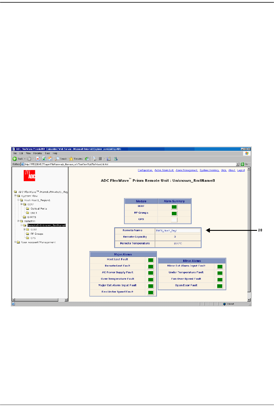
Initial Prism System Setup
Page 156 FlexWave Prism Host, Remote and EMS 5.1 System Reference
© 2009 ADC Telecommunications, Inc ADCP-77-073 • Issue 2 • 11/2009
6.7 ENTER A REMOTE NAME
A Remote becomes known to the EMS when an optical fiber is connected from the
Host to the Remote and IP has been enabled as described in “Provision the Host SeRF
Optical Ports” on page 151. The Remote appears as
Remote_Unknown_RmtName
in the
the EMS Function Explorer Tree of functions and can be renamed using the following
procedure.
Remotes are assigned a number from
1
through
8
that correspond to the physical SFP
port assignment on the Host. For example, SFP port 3 is
Remote3
.
277 In the Function Explorer Tree, select
System View
,
Remotes
,
Remote#-
x(where
Remote#
indicates the Remote number that corresponds to a Host SFP port
number and n is the Remote name).
Remote-Unknown_RmtName
is the default
Remote name until it is user-defined.
The
Remote Unit
view opens in the EMS View Frame. (For information on the alarms
shown in the
Remote Unit
view, see “Monitoring a Remote Unit” on page 240.)
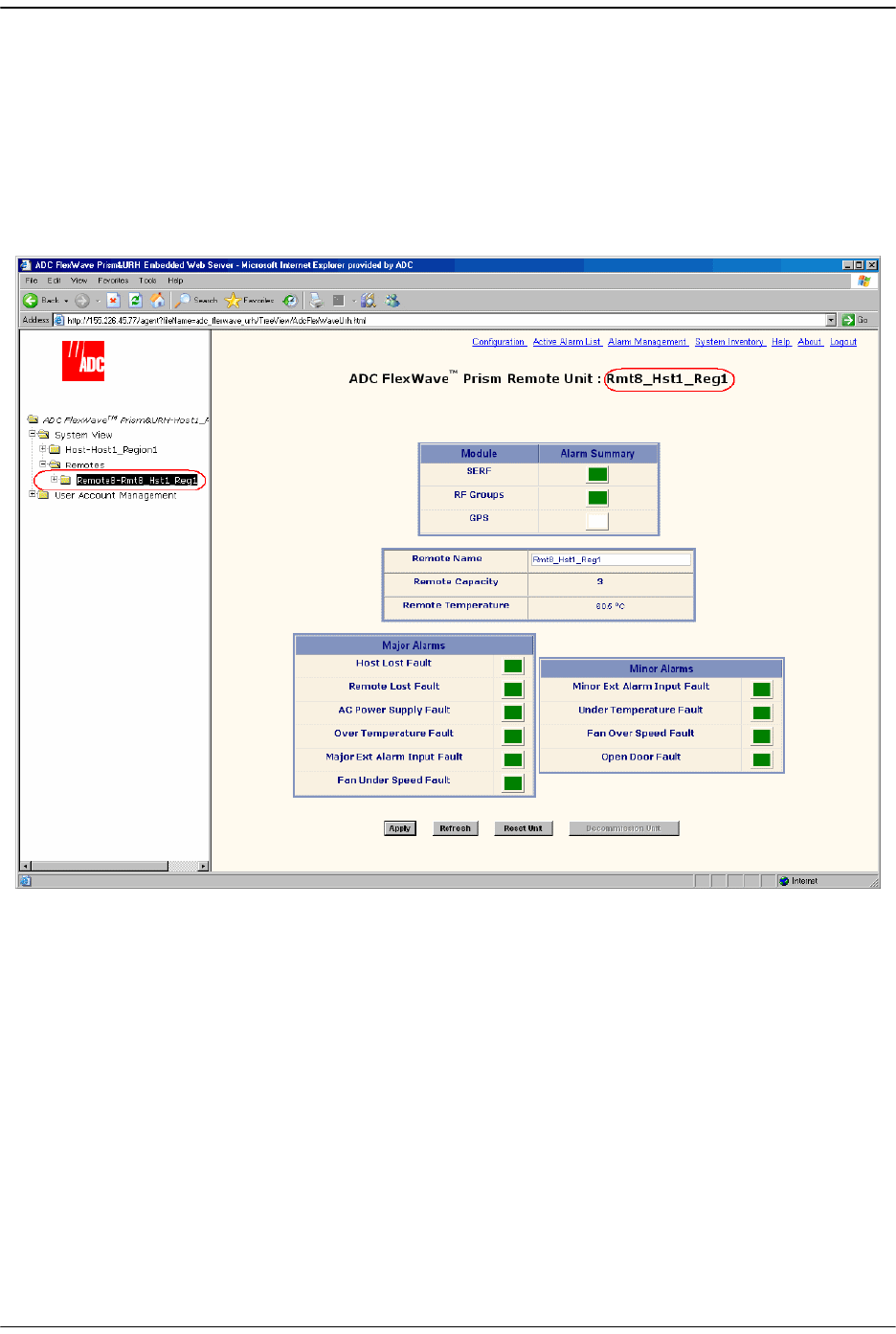
Enter a Remote Name
FlexWave Prism Host, Remote and EMS 5.1 System Reference Page 157
ADCP-77-073 • Issue 2 • 11/2009 © 2009 ADC Telecommunications, Inc.
288 In the
Remote Name
box, enter a name for the Remote. The Remote Name must be
between 5 and 40 characters with no spaces. The only special character allowed is
an underscore, but it cannot be the first character of the name. Numerals are
allowed, but cannot be the first character of the name.
299 Click
Apply
.
The new
Remote Name
is shown in the in the Function Explorer Tree and the
Remote
Unit
view.
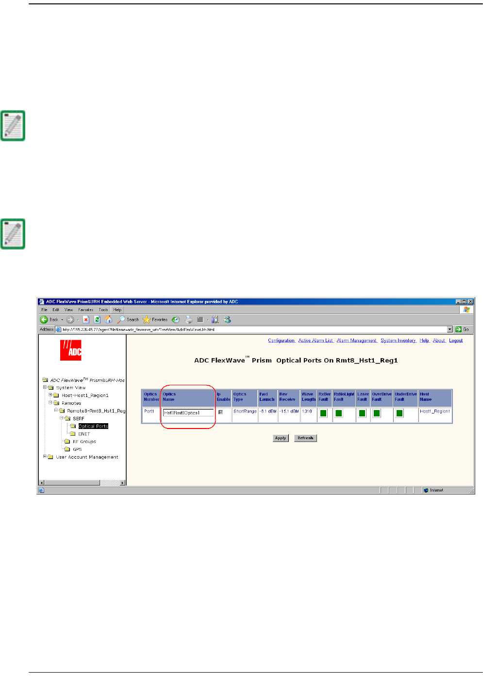
Initial Prism System Setup
Page 158 FlexWave Prism Host, Remote and EMS 5.1 System Reference
© 2009 ADC Telecommunications, Inc ADCP-77-073 • Issue 2 • 11/2009
6.8 CONFIGURE THE REMOTE SERF OPTICAL PORTS
300 In the Function Explorer Tree, select
System View
,
Remotes
,
Remote#-
x,
SERF
,
Optical
Ports
(where
Remote#
indicates the Remote number that corresponds to a Host SFP
port number and n is the Remote name).
The Optical Ports view for the selected Remote opens in the EMS View Frame.
311 In the
Optics Name
box, enter a label for the port that is between 5 and 32
characters with no spaces. The only special character allowed is an underscore,
but it cannot be the first character of the name. Numerals are allowed, but cannot
be the first character of the name.
322 Click
Apply
.
For information on the optical port indicators, see “Viewing Remote SeRF Optical Ports”
on page 248.
The Ip Enable field is not selectable for Remotes as it is configured at the Host SeRF
SFPs. Its inclusion in this view is to indicate which Remote SFP has IP on it. For
information on Ip Enable alarms, see “Viewing Host SeRF Optical Ports” on page 224.

Link the Host and Remote DARTs.
FlexWave Prism Host, Remote and EMS 5.1 System Reference Page 159
ADCP-77-073 • Issue 2 • 11/2009 © 2009 ADC Telecommunications, Inc.
6.9 LINK THE HOST AND REMOTE DARTS.
“Linking” establishes an association in software between a particular Host DART and
a particular Remote DART, enabling the two DARTs to act as an operational unit in
providing one RF band. There are four pre-requisites to this procedure:
•• The Host DART and Remote DART must be connected through the optical fiber
and be communicating with each other.
•• The Host DART card must be configured as described in “Configure the Host
DARTs” on page 152.
•• The Host and Remote DARTs must be of the same type (such as, Cellular or PCS).
•• There must be a sufficient number of fiber timeslots available in order to
accommodate the requested passband (for example, PCS A band requires 3
timeslots).
In the Remote DART configuration page, all Host DARTs are listed that have the same
band as the Remote DART. A link is established by selecting a Host DART to be paired
with the Remote DART.
6.9.1 Use of Multi Fibers
The EMS provides the ability to install “multi fibers” between a Host and Remote. This
means that, in addition to the minimum two fibers (RX and TX) in the Host to Remote
connection, one or more additional fiber pairs are installed. This is done to increase
the bandwidth between the Host and Remote. Each fiber pair can handle
approximately 75 Mbps of RF bandwidth.
Each fiber is capable of supporting 12 TDM timeslots:
•• Classic DARTs or Single SuperDARTs support up to 35 MHz of RF
– Cellular
–SMR800
–SMR900
– PCS Narrowband
–AWS Narrowband
–EGSM900
•• Dual SuperDARTs support up to 75 MHz of RF
– GSM1800
–UMTS
–AWS Fullband
If you are setting up a multi- host system, go to “(Optional) Configuring Multi-Host
Systems for Manual Mode” on page 168.
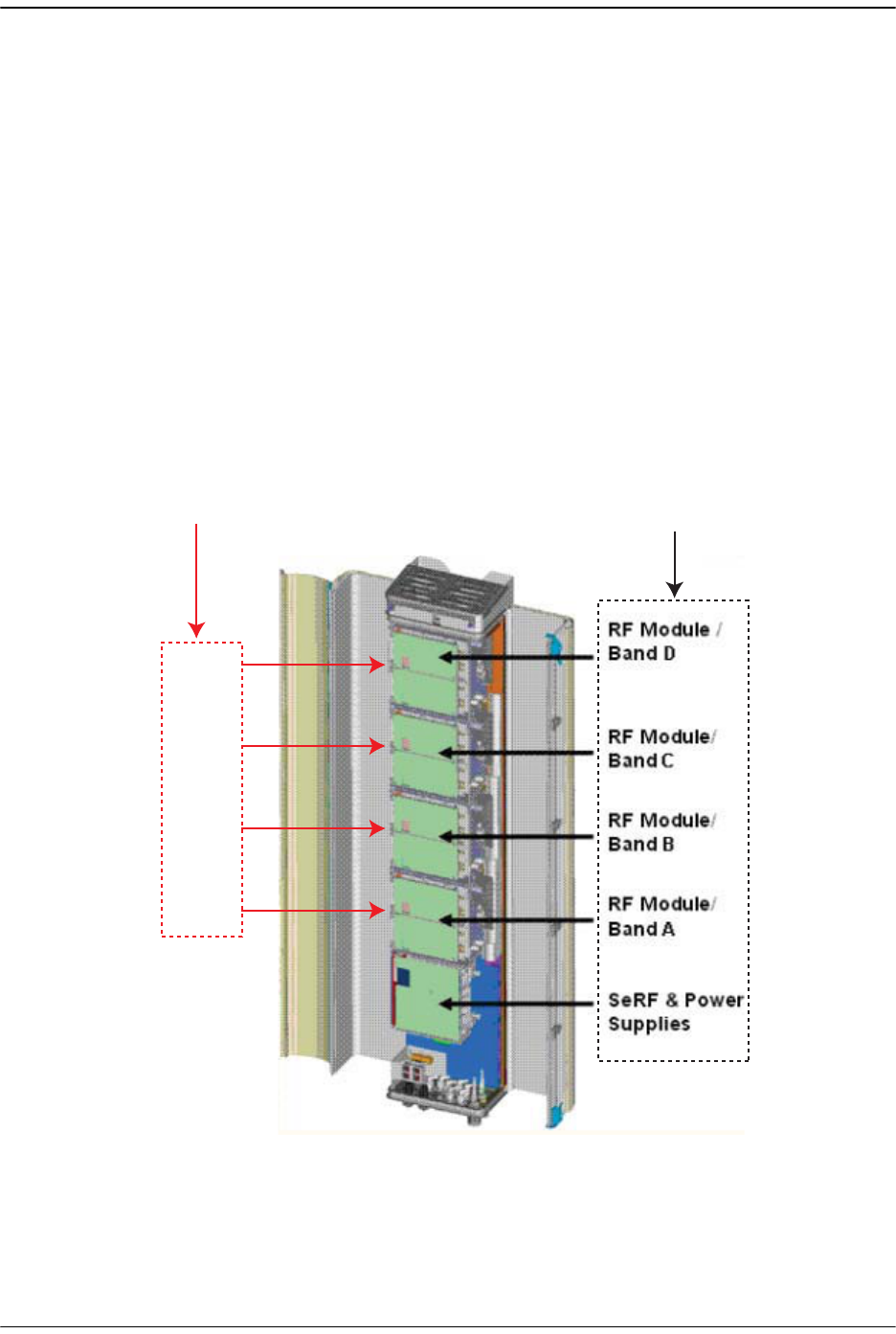
Initial Prism System Setup
Page 160 FlexWave Prism Host, Remote and EMS 5.1 System Reference
© 2009 ADC Telecommunications, Inc ADCP-77-073 • Issue 2 • 11/2009
When a Host DART is linked to a Remote DART in a multi-fibers configuration, the
EMS uses the first fiber (in numerical order) on which the required number of
timeslots is available for the passband being linked. The EMS will not divide up the
timeslots between two fibers. So, for example, if the passband requires eight
timeslots, and only six timeslots are available on the first fiber, the EMS will bypass
the first fiber and assign all eight timeslots to the second fiber, leaving four timeslots
unused on the second fiber.
6.9.2 RF Groups in the Remote and the EMS GUI
The EMS
Alarm Summary of RF Groups
view displays up to four rectangles labeled
RF
Module / Band N
(where
N
equals
A
,
B
,
C
, or
D)
. Each rectangle represents one RF Module
in the Remote. Figure 6-1 shows how the FlexWave EMS maps the RF Modules in the
GUI to the physical modules and antennas.
Figure 6-1. Matching Remote RF Modules to EMS Group Labels
Figure 6-2 shows the
Alarm Summary of RF Groups
view. If a slot is not occupied by an
RF Module, the slot is shown with a white indicator.
MOD A
MOD B
MOD C
MOD D
Remote
RF Module
shelf labels
EMS
RF Module
labels
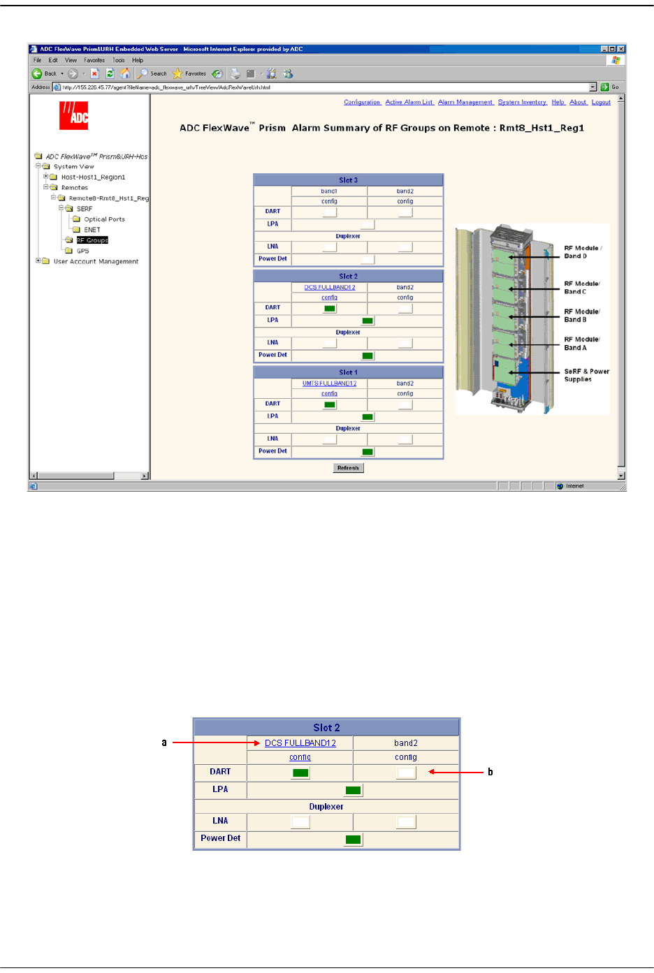
Link the Host and Remote DARTs.
FlexWave Prism Host, Remote and EMS 5.1 System Reference Page 161
ADCP-77-073 • Issue 2 • 11/2009 © 2009 ADC Telecommunications, Inc.
Figure 6-2. Alarm Summary of RF Groups View
Figure 6-3 provides a close up view of the
Slot 2
panel in the
Alarm Summary of RF
Groups
view where:
•
a
:
DCS FULLBAND12
indicates that a 12-slot DCS FullBand DART is plugged into
band1
.
•
b
: An expander for the DCS FullBand DART is plugged into
band2
and therefore is
represented with a White indicator to indicate that a configurable DART is not
present.
Figure 6-3. RF Groups in the FlexWave EMS
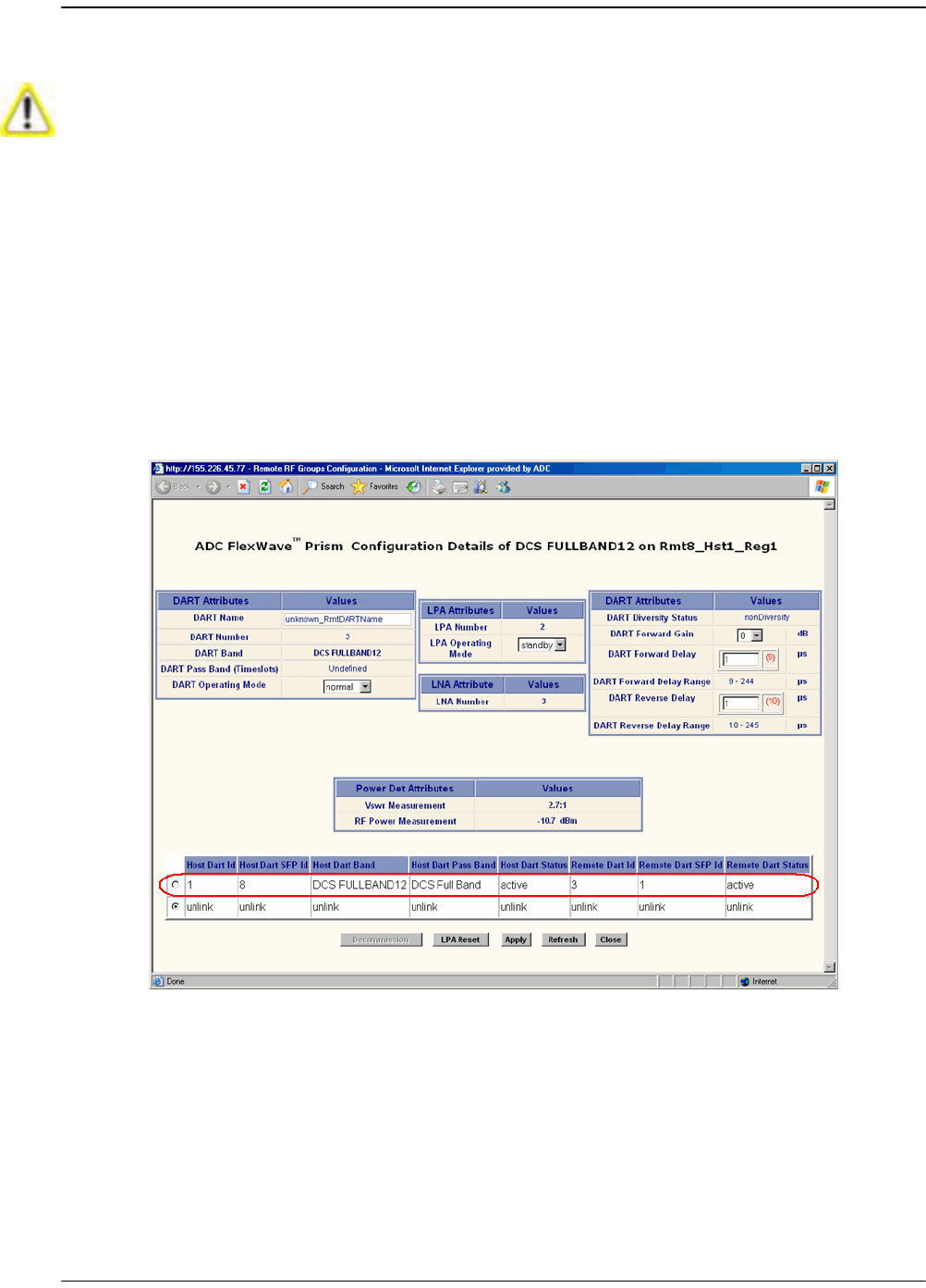
Initial Prism System Setup
Page 162 FlexWave Prism Host, Remote and EMS 5.1 System Reference
© 2009 ADC Telecommunications, Inc ADCP-77-073 • Issue 2 • 11/2009
6.9.3 Link a Remote DART to a Host DART
333 Verify that the Host DART is configured as described in “Configure the Host
DARTs” on page 152.
344 In the Function Explorer Tree, select
System View
,
Remotes
,
Remote#-
x,
SERF
,
RF
Groups
(where
Remote#
indicates the Remote number that corresponds to a Host
SFP port number and n is the Remote name) to open the
Alarm Summary of RF Groups
view (see Figure 6-2 on page 161).
355 In the rectangle for the RF group selected, click on the
config
link for the band
being linked to open a
Configuration Details
window that corresponds to the
selected link.
The table at the bottom of the
Configuration Details
window indicates which Host
Unit DART is available for use in linking. In this example, the display indicates
that
Host DART ID 1
(top row, circled in red) is assigned to
DCS Full Band
.
This procedure requires that the antenna has been connected and the system is ready
to transmit RF. For information on connecting the antenna, see “Antenna Cable
Installation” on page 123.
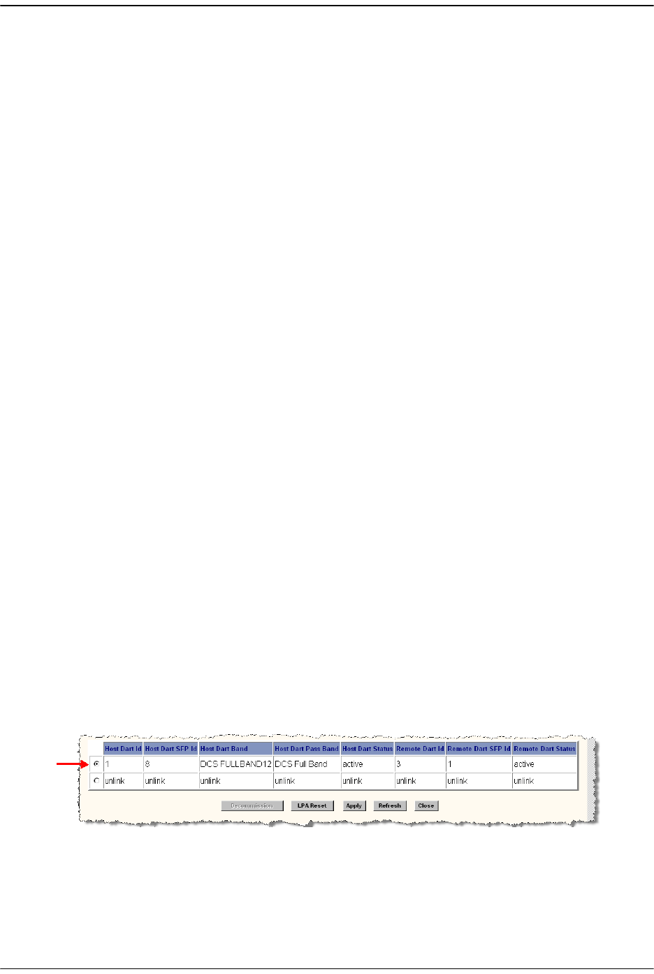
Link the Host and Remote DARTs.
FlexWave Prism Host, Remote and EMS 5.1 System Reference Page 163
ADCP-77-073 • Issue 2 • 11/2009 © 2009 ADC Telecommunications, Inc.
The
Configuration Details
table has the following columns:
•
Host DART Id
—Slot number of slot occupied by the Host DART card. The Host
has eight slots numbered from 1 to 8, read from top to bottom. If the Host
DART is a 12-Timeslot DART, then only the first of the two slots it occupies
will be shown (for example, if the Host 12-Timeslot DART occupies slots 1 and
3, only slot 1 will be shown).
•
Host DART SFP Id
—Port number of physical optical port where Host-Remote
optical fiber is connected on the Host.
•
Host DART Band
—Frequency band of the Host DART. This field is not
configurable and reports the DART type (such as, cellular, pcs, and so forth).
•
Host DART Pass Band
—Passband assigned to the specified Host DART.
•
Host DART Status
—System entered status of Host DART card. This will be active,
standby, or not in service
•
Remote DART Id
—Number (1-8) indicating the physical location where this
DART card is mounted in the Remote; see “RF Groups in the Remote and the
EMS GUI” on page 160) for an explanation of how the Remote DARTs are
numbered.
•
Remote DART SFP Id
—Shows the available Remote SFPs that can be used to link
the DARTs.
1
is shown in this example, so the Remote has fibers connected to
this Host using Remote SFP 1. If there are two or more sets of SFPs connected
between the same Host DART and Remote DART, this field will contain a value
such as
2/3
or
2/3/4
where each one-digit number represents one Remote
optical port where an SFP is connected for this Host/Remote pair. Each set of
one Host SFP and one Remote SFP supports two optical fibers (RX and TX), each
with a capacity of 12 TDM timeslots
•
Remote DART Status
—System entered status of Remote DART card, which can
be
active
or
unlink
•
Decommission
button—used to clean out settings and information for
hardware that has been removed.
•
LPA Reset
button—When clicked, causes the LPA to reset as described in
“Restarting an LPA” on page 236.
366 To link the Host DART to the Remote DART for this pass band, click in the radio
button next to Host DART Id (ID
1
in this example).
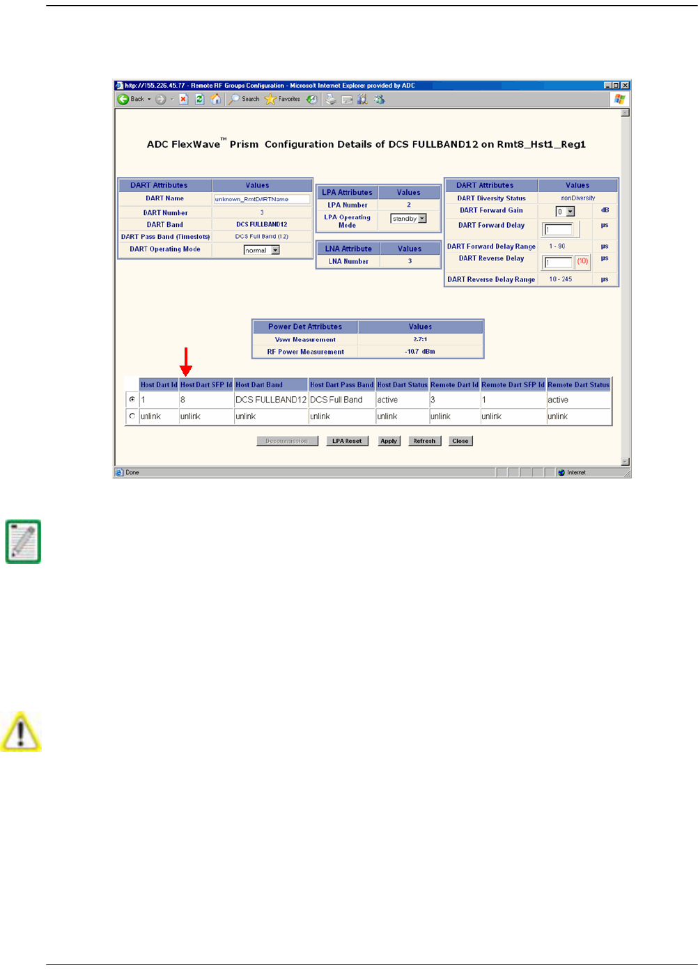
Initial Prism System Setup
Page 164 FlexWave Prism Host, Remote and EMS 5.1 System Reference
© 2009 ADC Telecommunications, Inc ADCP-77-073 • Issue 2 • 11/2009
377 Click
Apply
. The following example shows the completed link (in this case,
Host
DART SFP Id 8
has been selected).
388 Set the
LPA Operating Mode
to
normal
.
If multi fibers are connected between the Host and Remote, the system will try the fibers
in numerical sequence until a link can be established for the identified passband. If no
fiber is available providing the number of TDM timeslots required for the passband, an
error message is returned indicating that “DART linking failed due to a problem on the
host.”
If adding a link to an existing simulcast connection, the system requires the use of the
same timeslots. If the timeslots aren't available, the system returns the following error
message: “DART linking failed due to a problem on the host.”
As soon as you set the LPA Operating Mode to normal, RF transmission will start. Before
you set the LPA Operating Mode to normal, make sure that the antenna has been
connected and the system is ready to transmit RF. For information on connecting the
antenna, see “Antenna Cable Installation” on page 123.
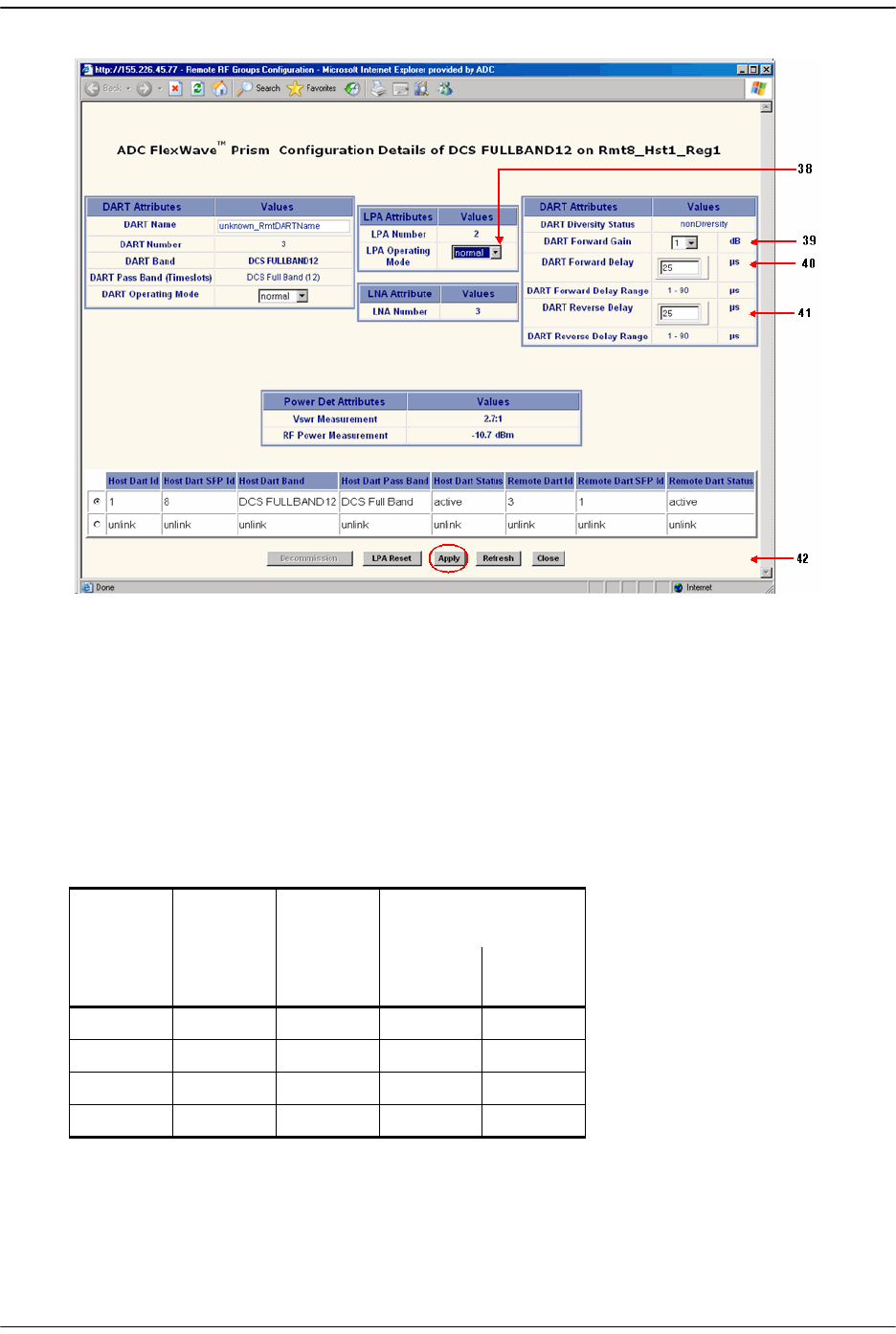
Link the Host and Remote DARTs.
FlexWave Prism Host, Remote and EMS 5.1 System Reference Page 165
ADCP-77-073 • Issue 2 • 11/2009 © 2009 ADC Telecommunications, Inc.
399 In the
DART Forward Gain
list, select the dB (
0
to
31
), which is the actual gain, not
attenuation, that will be applied to the RF forward path signal (where
0
=
0 dB gain
,
1
=
1 dB gain
, and so forth) The DART Forward Gain is based on the EIRP desired
at the antenna. You therefore need to know how much cable, insertion, and any
other loss (such as splitters) exist between the Remote and the antenna. Set the
DART Forward Gain
to achieve the required output power level to meet the EIRP of
your RF link budget.
The following table provides calculations you need to set the gains to achieve the
desired Output power for a single-DART configuration.
For dual-DART configurations, you need to reduce each path by 3dB at the Remote
DART Forward Gain
. For example, for a DART Input Level of -25dBm, the Host FWD
Gain setting would be 31dB and the Remote FWD Gain setting would be 28dB.
DART
Input
Level
Host
DART
Fwd Gain
Remote
DART
Fwd Gain
Expected Output
(in dBm)
20W
DART
6.5W
DART
-25 31 31 43 38
-25 31 012 7
+6 031 43 38
+6 0 0 12 7

Initial Prism System Setup
Page 166 FlexWave Prism Host, Remote and EMS 5.1 System Reference
© 2009 ADC Telecommunications, Inc ADCP-77-073 • Issue 2 • 11/2009
400 In the
DART Forward Delay
box, set in microseconds the actual delay that will be
applied to the RF forward path signal. The minimum delay required is calculated.
The acceptable range of delays is 88us. If you attempt to set the delay to a value
outside the allowed range, the DART uses either the minimum or maximum,
dependant on whether the DART is exceeding the set delay (too high or low).
Be aware of simulcast links. Observe the minimum delay required for the longest
link, and set the delay to the same value for all simulcast nodes in the same
connection based on this value.
Here is an example:
•• Fiber has 8 usec per mile of fiber.
•• Remote 1 has 5 miles of fiber (40 usec of fiber delay).
•• Remote 2 has 10 miles of fiber (80 usec of fiber delay).
•• Remotes are set to Cellular A"/A Band which has 8 usec of system delay. The
delay ranges will therefore be:
– Remote 1 delay (48-136)
– Remote 2 delay (88-176)
The system calculates these delay values—this is a typical example based on the fiber
lengths provided. You select a delay value that’s within the range calculated by the
system.
Set the delays to the same values for all nodes in the network in order to:
•• Optimize simulcast
•• Make BTS datafill changes simple (same delay offsets for all nodes)
•• Simplify E-911 integration (same delay offsets for all nodes)
Delays cannot be shortened; they can only be lengthened. The recommended
approach is to normalize all Remotes to the longer minimum delay. In this
example the delay would therefore have to be 88 usec.
411 In the
DART Reverse Delay
box, set in microseconds the actual delay that will be
applied to the RF reverse path signal. The actual delay of the RF path will be within
1 usec. For E-911 TDOA applications, the reverse path delay must be measured to
achieve the +/- 50 nsec delay accuracy specified for DAS networks. The FWD and
REV delay values are usually the same because the fiber path between the two is
typically the same.
422 Click
Apply
.

Conclude Initial System Setup
FlexWave Prism Host, Remote and EMS 5.1 System Reference Page 167
ADCP-77-073 • Issue 2 • 11/2009 © 2009 ADC Telecommunications, Inc.
6.10 CONCLUDE INITIAL SYSTEM SETUP
The FlexWave system is now ready for use and further configuration as described in
this document.
The default admin user account has unrestricted access to all EMS user accounts and
management capabilities. To protect against unauthorized access to the Prism network,
as soon as possible, the user assigned the admin role should follow the process
described “Changing Your Own Password” on page 208 to change the password for the
default admin user.

Initial Prism System Setup
Page 168 FlexWave Prism Host, Remote and EMS 5.1 System Reference
© 2009 ADC Telecommunications, Inc ADCP-77-073 • Issue 2 • 11/2009
6.11 (OPTIONAL) CONFIGURING MULTI-HOST SYSTEMS
FOR MANUAL MODE
When the Prism system is set to Automated linking mode, you establish a link in the
Configuration Details
window by selecting the Host DART to link to and then clicking
Apply
(see “Link a Remote DART to a Host DART” on page 162). The link is then
established on both the Host and Remote ends, using the fiber and the timeslots that
are automatically selected by the FlexWave EMS. The Remote DART also automatically
adopts the Host DART's pass band and diversity setting.
Multi-Host systems must be set to Manual linking mode so each side of the link (Host
and Remote) can be established independently. The Network Administrator must also
manually specify the fiber, timeslots, pass band, and diversity status for each end.
There is no system crosscheck to validate the selections—so the setup described in
this section should be performed only by an administrator who is very familiar with
the concepts involved.
6.11.1 Set the Multi-Host System to Manual Mode
11 In the Function Explorer Tree, select
System View
,
Host-Unknown_HostName
to open
the
Host Summary
view in the EMS View Frame. (For information on the read-only
status indicators in the
Host Summary
view, see “Viewing the Host Summary” on
page 214.)
22 In the
Linking Mode
list, select
Manual
.
33 Click
Apply
.
6.11.2 Configure the Host DARTs
44 In the Function Explorer Tree, select
System View
,
Host-
x,
SERF
,
DARTS
(where
-
x is
the Host name) to open the
DART’s Alarm Summary
view in the EMS View Frame.
The
DART’s Alarm Summary
view displays all the Host DARTS that are present,
starting from slot 1 at the top of the list and working sequentially down to last
DART, which can be slots 1-8.
55 In the
Information
column, click on the
Band-Config
link for the DART to be
configured.
You can only switch between the Automated and Manual modes when there are no active
links in the system. Once a link is established the mode is locked and selections in the
Linking Mode list are disabled. All active links must be unlinked to enable the selections
in the Linking Mode list.
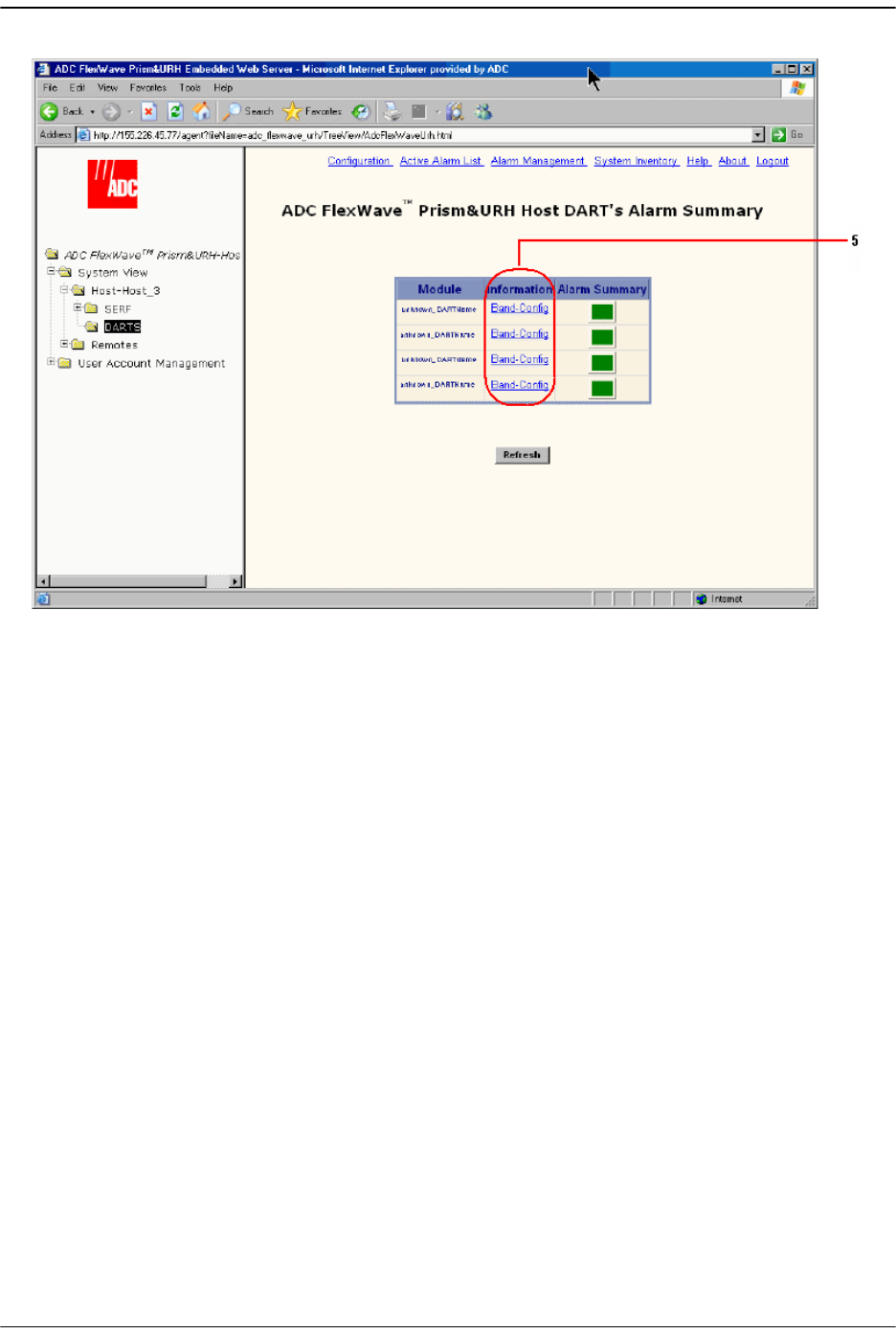
(Optional) Configuring Multi-Host Systems for Manual Mode
FlexWave Prism Host, Remote and EMS 5.1 System Reference Page 169
ADCP-77-073 • Issue 2 • 11/2009 © 2009 ADC Telecommunications, Inc.
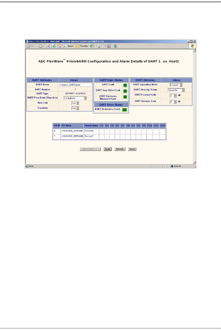
Initial Prism System Setup
Page 170 FlexWave Prism Host, Remote and EMS 5.1 System Reference
© 2009 ADC Telecommunications, Inc ADCP-77-073 • Issue 2 • 11/2009
66 In the
Configuration and Alarm Details of DART n
window that opens, set the
DART
Attributes
. The table at the bottom of the
Configuration and Alarm Details of DART n
window shows how many SFPs have been discovered that are available for
linking—their corresponding timeslots are blank.
aa In the
DART Name
box, enter a name for the DART between 5 and 32 characters
with no spaces. The only special character allowed is an underscore, but it
cannot be the first character of the name. Numerals are allowed, but cannot be
the first character of the name.
bb In the
DART Pass Band (Timeslots)
list, select the DART Pass Band to be
supported by this DART. The list will include only those pass bands that are
valid selections for the DART band. For example, if the DART band is
“cellular,” only cell pass bands are listed.
cc In the
New Link
list, select the SFP ID for the fiber to be used to communicate
with the Remote for the DART's RF. Only the IDs of fiber with enough available
contiguous timeslots for the selected passband will be available in the
New Link
list. The table in the lower part of the screen shows which fibers are available
and which timeslots on the fibers are in use. Be careful to select a fiber to the
Remote to which you want to link.
dd In the
Timeslots
list, select the timeslots on the fiber that will carry the RF. The
Timeslots
list displays the range of timeslots that can be used—only unused
timeslots will be available for selection. If the DART is already linked to a
Remote, the
Timeslots
list comprises the timeslots being used for that previous
link. If you are linking to more than one Remote, the same timeslots must be
used on all fibers for this DART.
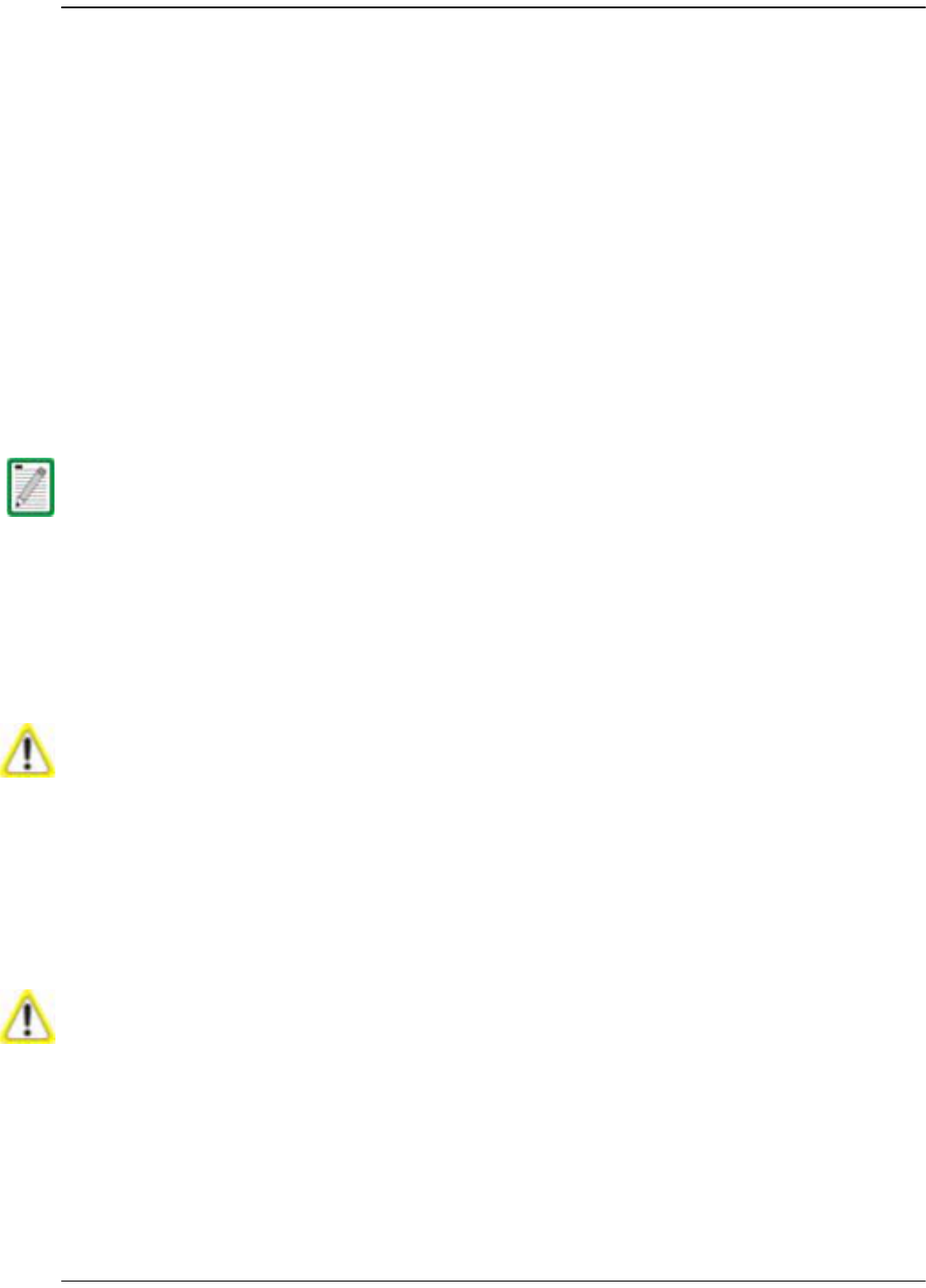
(Optional) Configuring Multi-Host Systems for Manual Mode
FlexWave Prism Host, Remote and EMS 5.1 System Reference Page 171
ADCP-77-073 • Issue 2 • 11/2009 © 2009 ADC Telecommunications, Inc.
ee In the
DART Operating Mode
list, select one of the following:
•
Standby
—forces the RF function to be muted in the Host and its linked
Remote.
•
Normal
—allows the system to operate normally (RF function not forced to
be muted), assuming all other system components are in proper working
order. (Default setting.)
The mode
Undefined
is not user selectable, and indicates that the EMS is
unaware of the current mode.
ff In the
DART Diversity Status
list, select
nonDiversity
or
diversity
. For a diversity
application, one DART will be configured
nonDiversity
for the primary
FWD/REV path signal and the other DART will be configured
Diversity
. This
selection therefore determines whether the DART card being configured will
carry the primary or secondary RF path.
For dual DART configurations, such as dual-pcs, smr800/smr900 and
dual-aws, both DARTs must have
DART Diversity Status
set to
nonDiversity
.
gg In the
DART Forward Gain
list, set this value (0 to 31 dB) based upon the fully
loaded forward path signal level from the Base Station. The Host DART expects
signal levels from
-25
to
+5 dBm
. If the fully loaded signal is +5 dBm, then the
DART forward gain should be set to 0 dB, if the fully loaded signal is -25 dBm,
then the DART Forward Gain should be set to 30 dB. The equation is:
DART Forward Gain = 5 - fullyLoadedBasestationSignal.
The diversity status of the Host DART will not extend to the Remote DART connected to
it. You must explicitly configure the Remote DART to have the same diversity status as
the Host DART.
If you are setting up the system when no calls are going through, you must allow
headroom for a fully loaded forward path. For CDMA protocols, the difference from
unloaded to fully loaded is typically 8dB, so if the unloaded signal is - 15dBm, then the
fully loaded input would be - 7 dBm and the Host Forward Gain should be set to 5- (- 7)
= 12 dB.
The same rules applies for GSM carriers, except that the unloaded to loaded is
determined by the equation 10*log10(# RF Channels). So if there are 4 GSM RF Channels,
then the loaded forward path is 6 dB above unloaded.
If sufficient headroom is not present, then the LPA can be over- powered causing a Loss
Of Service.
When configured correctly, the Host DART Forward input can handle peaks of 14dB
above the BTS signal level. For example, if the fully loaded CDMA carrier is - 25dBm, then
peaks up to - 11 dBm can be handled (CDMA peak to average is typically 10- 12 dB). If
the peaks exceed the 14 dB of headroom, then Automatic Level Control (ALC) will occur
to prevent over- driving the A/D Converter.
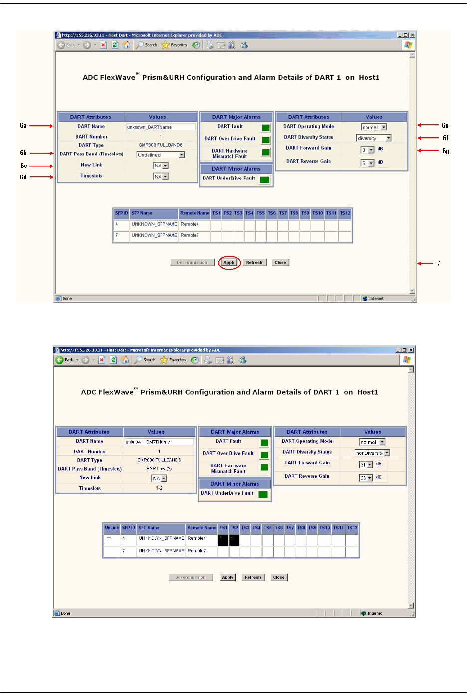
Initial Prism System Setup
Page 172 FlexWave Prism Host, Remote and EMS 5.1 System Reference
© 2009 ADC Telecommunications, Inc ADCP-77-073 • Issue 2 • 11/2009
77 Click
Apply
.

(Optional) Configuring Multi-Host Systems for Manual Mode
FlexWave Prism Host, Remote and EMS 5.1 System Reference Page 173
ADCP-77-073 • Issue 2 • 11/2009 © 2009 ADC Telecommunications, Inc.
88 Click
Close
.
6.11.3 Configure the Remote DARTs
99 Login to the web server on the Host that is managing the Remote (that is, the Host
has IP enabled to the remote). This may be the Host you are currently logged into
or could be a different Host in the Multi-Host group.
100 In the Function Explorer Tree, select
System View
,
Remotes
,
Remote#-
x,
SERF
,
RF
Groups
(where
Remote#
indicates the Remote number that corresponds to a Host
SFP port number and n is the Remote name) to open the
Alarm Summary of RF Groups
view (see Figure 6-2 on page 161).
111 In the rectangle for the RF group selected, click on the
config
link for the band
being linked to open a
Configuration Details
window that corresponds to the
selected link.
122 In the
Configuration Details of DART n on Remote
Nwindow that opens, set the
DART
Attributes
. The table at the bottom of the
Configuration and Alarm Details of DART n
window shows how many SFPs have been discovered that are available for
linking—their corresponding timeslots are blank.
aa In the
DART Name
box, enter a name for the DART between 5 and 32 characters
with no spaces. The only special character allowed is an underscore, but it
cannot be the first character of the name. Numerals are allowed, but cannot be
the first character of the name.
bb In the
DART Pass Band (Timeslots)
list, select the DART Pass Band to be
supported by this DART. The list will include only those pass bands that are
valid selections for the DART band. For example, if the DART band is
“cellular,” only cell pass bands are listed.
cc In the
New Link
list, select the SFP that you want to link.
dd In the
Timeslots
list, select the timeslot for the SFP. If the DART is already
linked, the
Timeslots
list is read-only and displays the range of timeslots
occupied by the DART.
ee In the
DART Operating Mode
list, select one of the following:
•
Standby
—forces the RF function to be muted in the Host and its linked
Remote.
•
Normal
—allows the system to operate normally (RF function not forced to
be muted), assuming all other system components are in proper working
order. (Default setting.)
The mode
Undefined
is not user selectable, and indicates that the EMS is
unaware of the current mode.
ff In the
DART Diversity Status
list, select
nonDiversity
or
diversity
. For a diversity
application, one DART will be configured
nonDiversity
for the primary
To unlink a Host DART from a Remote, click on the checkbox in the fiber timeslot table
for the Remote being unlinked, and then click Apply.
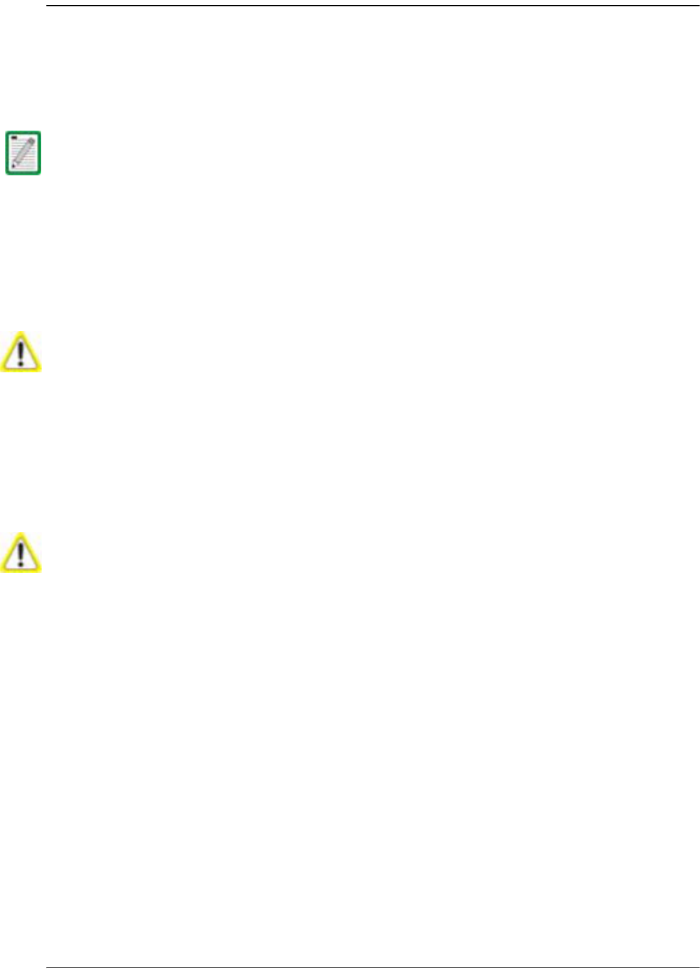
Initial Prism System Setup
Page 174 FlexWave Prism Host, Remote and EMS 5.1 System Reference
© 2009 ADC Telecommunications, Inc ADCP-77-073 • Issue 2 • 11/2009
FWD/REV path signal and the other DART will be configured
Diversity
. This
selection therefore determines whether the DART card being configured will
carry the primary or secondary RF path.
For dual DART configurations, such as dual-pcs, smr800/smr900 and
dual-aws, both DARTs must have
DART Diversity Status
set to
nonDiversity
.
gg In the
DART Forward Gain
list, set this value (0 to 31 dB) based upon the fully
loaded forward path signal level from the Base Station. The Host DART expects
signal levels from
-25
to
+5 dBm
. If the fully loaded signal is +5 dBm, then the
DART forward gain should be set to 0 dB, if the fully loaded signal is -25 dBm,
then the DART Forward Gain should be set to 30 dB. The equation is:
DART Forward Gain = 5 - fullyLoadedBasestationSignal.
hh In the
DART Forward Delay
box, set in microseconds the actual delay that will be
applied to the RF forward path signal. The minimum delay required is
calculated. The acceptable range of delays is 88us. If you attempt to set the
delay to a value outside the allowed range, the DART uses either the minimum
or maximum, dependant on whether the DART is exceeding the set delay (too
high or low).
Be aware of simulcast links. Observe the minimum delay required for the
longest link, and set the delay to the same value for all simulcast nodes in the
same connection based on this value.
Here is an example:
•• Fiber has 8 usec per mile of fiber.
•• Remote 1 has 5 miles of fiber (40 usec of fiber delay).
•• Remote 2 has 10 miles of fiber (80 usec of fiber delay).
The diversity status, fiber, and timeslots of the Host DART must match the Remote
DART linked to it.
If you are setting up the system when no calls are going through, you must allow
headroom for a fully loaded forward path. For CDMA protocols, the difference from
unloaded to fully loaded is typically 8dB, so if the unloaded signal is - 15dBm, then the
fully loaded input would be - 7 dBm and the Host Forward Gain should be set to 5- (- 7)
= 12 dB.
The same rules applies for GSM carriers, except that the unloaded to loaded is
determined by the equation 10*log10(# RF Channels). So if there are 4 GSM RF Channels,
then the loaded forward path is 6 dB above unloaded.
If sufficient headroom is not present, then the LPA can be over- powered causing a Loss
Of Service.
When configured correctly, the Host DART Forward input can handle peaks of 14dB
above the BTS signal level. For example, if the fully loaded CDMA carrier is - 25dBm, then
peaks up to - 11 dBm can be handled (CDMA peak to average is typically 10- 12 dB). If
the peaks exceed the 14 dB of headroom, then Automatic Level Control (ALC) will occur
to prevent over- driving the A/D Converter.
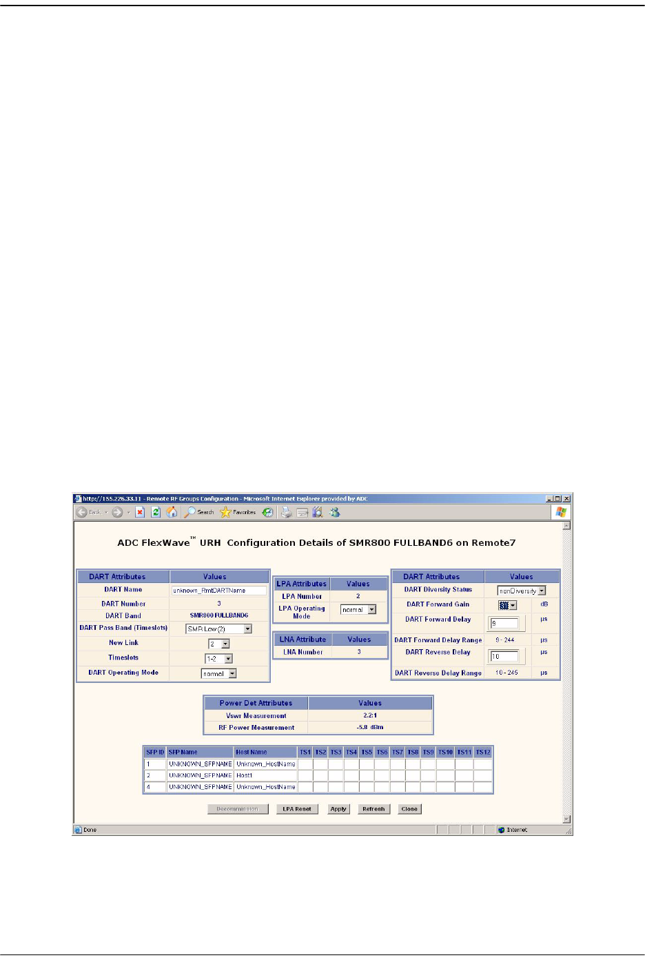
(Optional) Configuring Multi-Host Systems for Manual Mode
FlexWave Prism Host, Remote and EMS 5.1 System Reference Page 175
ADCP-77-073 • Issue 2 • 11/2009 © 2009 ADC Telecommunications, Inc.
•• Remotes are set to Cellular A"/A Band which has 8 usec of system delay.
The delay ranges will therefore be:
– Remote 1 delay (48-136)
– Remote 2 delay (88-176)
The system calculates these delay values—this is a typical example based
on the fiber lengths provided. You select a delay value that’s within the
range calculated by the system.
Set the delays to the same values for all nodes in the network in order to:
•• Optimize simulcast
•• Make BTS datafill changes simple (same delay offsets for all nodes)
•• Simplify E-911 integration (same delay offsets for all nodes)
Delays cannot be shortened; they can only be lengthened. The
recommended approach is to normalize all Remotes to the longer
minimum delay. In this example the delay would therefore have to be 88
usec.
ii In the
DART Reverse Delay
box, set in microseconds the actual delay that will be
applied to the RF reverse path signal. The actual delay of the RF path will be
within 1 usec. For E-911 TDOA applications, the reverse path delay must be
measured to achieve the +/- 50 nsec delay accuracy specified for DAS
networks. The FWD and REV delay values are usually the same because the
fiber path between the two is typically the same.
133 Click
Apply
.
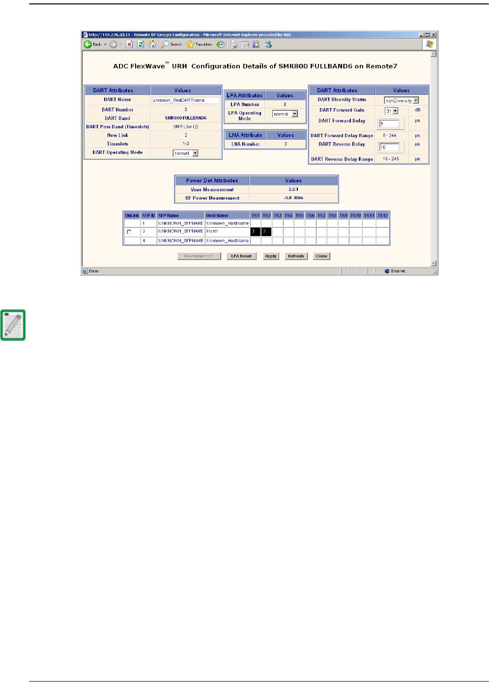
Initial Prism System Setup
Page 176 FlexWave Prism Host, Remote and EMS 5.1 System Reference
© 2009 ADC Telecommunications, Inc ADCP-77-073 • Issue 2 • 11/2009
144 Click
Close
.
To unlink the Remote DART, click on the checkbox in the fiber timeslot table (at the
bottom of the window) in the Unlink column and then click Apply.

FlexWave Prism Host, Remote and EMS 5.1 System Reference Page 177
ADCP-77-073 • Issue 2 • 11/2009 ©2009 ADC Telecommunications, Inc.
7USING THE EMS TO MANAGE A PRISM
SYSTEM
7.1 Displaying the System View ...............................................................................178
7.2 Setting Auto Refresh.........................................................................................179
7.3 Working with the System Inventory ....................................................................180
7.3.1 System Inventory View Components ...........................................................180
7.3.1.1 System Inventory and Host Inventory Tables........................................181
7.3.1.2 Remote Inventory Tables ...................................................................182
7.4 Working with Prism System Network Interfaces....................................................184
7.4.1 Changing to Built-In Network Mode.............................................................186
7.4.2 EMS Access Methods.................................................................................188
7.4.2.1 Accessing the EMS Through the Remote Network Port............................189
7.4.2.2 Accessing the EMS Through the Remote Craft Port ................................192
Content Page
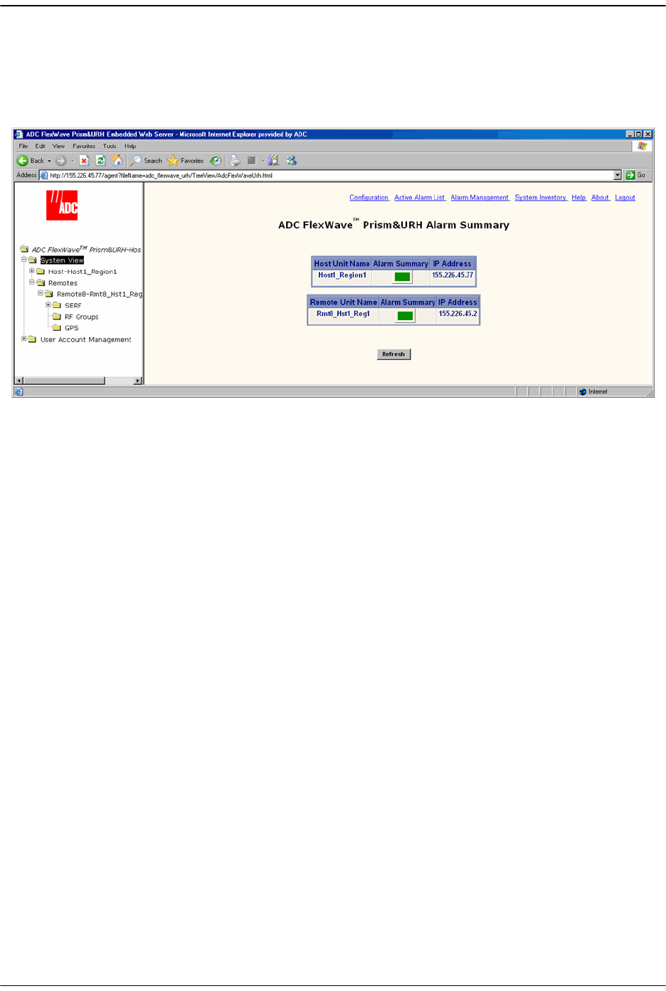
Using the EMS to Manage a Prism System
Page 178 FlexWave Prism Host, Remote and EMS 5.1 System Reference
© 2009 ADC Telecommunications, Inc ADCP-77-073 • Issue 2 • 11/2009
7.1 DISPLAYING THE SYSTEM VIEW
In the Function Explorer Tree, click on
System View
to open the system view, which is
labeled as the
Alarm Summary
, in the EMS View Frame.
The
Alarm Summary
provides a top-level view of the Prism system, which identifies the
Host and all Remotes known to the EMS by their IP addresses and provides a
summary alarm status indicator for each unit.
•
Host Unit Name
—name entered by user or
Unknown_HostName
if no name has been
entered. Current summary alarm state of Host is indicated by status indicator in
same row.
•
Alarm Summary
indicator—indicates if the state of the unit:
– Green indicates a Normal state
– Yellow indicates that a Minor alarm is active, and is the highest-level active
alarm
– Red indicates that a Major alarm is active.
•
Remote Unit Name
—name entered by user or
Unknown_RmtName
if no name has
been entered. Summary alarm state is indicated by status indicator in same row.
•
IP Address
(Host/Remote)—IP Address of the Host/Remote. If logged into a Remote
that is not connected to a Host, the Host IP Address will appear as
NOT_CONNECTED
, and the Remote IP Address will appear as
0.0.0.0
if the remote
is setup for DHCP. If a static IP address has been assigned to the Remote, the
actual IP address for the Remote will display when the Host is not connected.
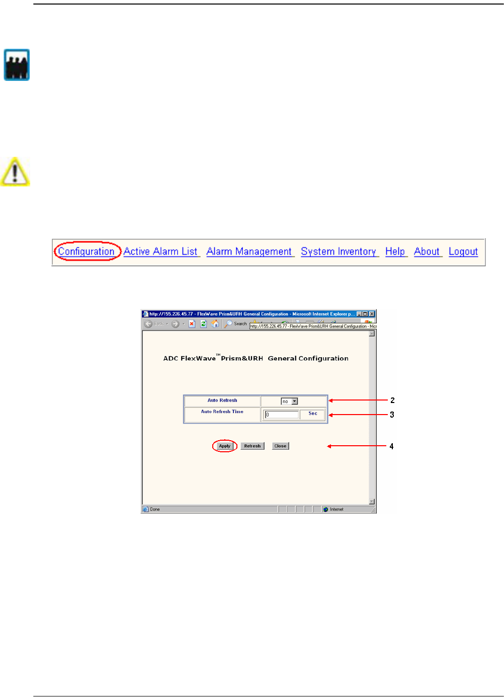
Setting Auto Refresh
FlexWave Prism Host, Remote and EMS 5.1 System Reference Page 179
ADCP-77-073 • Issue 2 • 11/2009 © 2009 ADC Telecommunications, Inc.
7.2 SETTING AUTO REFRESH
Auto Refresh is intended for use after the Prism system has been configured during
initial setup and you want to monitor system performance without having to trigger
manual page refreshes.
11 In the EMS Menu bar, click
Configuration.
The
General Configuration
window opens.
22 In the
Auto Refresh
list, select
yes
to set the EMS pages to auto refresh.
33 In the
Auto Refresh Time
box, enter the number of seconds (
1
-
1800
) between EMS
auto refreshes.
44 Click
Apply
.
Only a user logged in under the admin or a Network Manager account can change Prism
settings through the EMS.
Do not set Auto Refresh until after the initial Prism system setup described in “Initial
Prism System Setup” on page 143. If you apply Auto Refresh before initial system setup,
entered configurations can be lost.
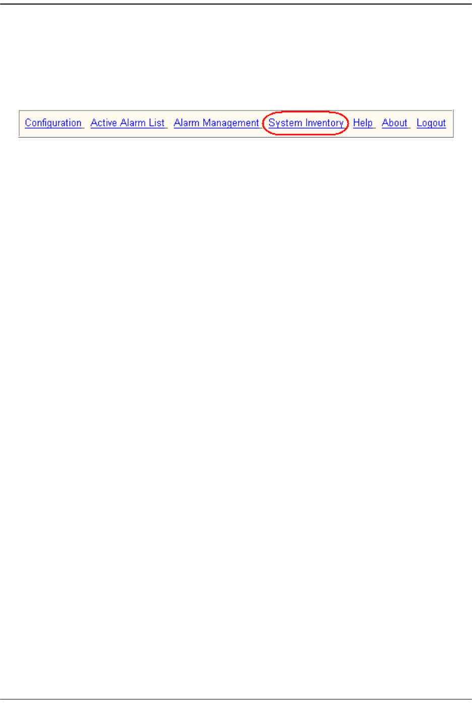
Using the EMS to Manage a Prism System
Page 180 FlexWave Prism Host, Remote and EMS 5.1 System Reference
© 2009 ADC Telecommunications, Inc ADCP-77-073 • Issue 2 • 11/2009
7.3 WORKING WITH THE SYSTEM INVENTORY
The
System Inventory
view identifies the main software and hardware components of
the current, working system.
11 To open the
System Inventory
view, in the EMS Menu bar, click
System Inventory.
22 Confirm that the Host and its Remotes are operating at the same software revision
by looking at the values displayed in the
Compact Flash SwVer
column.
33 Confirm that all installed devices are displayed in the
Hardware Inventory
table:
•• Host
–SeRFs
–DART
–System card
•• Remotes
– One RSI per connected Remote
– One SeRF per connected Remote
•• Remote RF Modules
–One RDI
– Power Detector
– One or two DARTs, depending on configuration.
– One or two LNAs, depending on configuration.
7.3.1 System Inventory View Components
The
System Inventory
view is a too long to present in one graphic. This document
therefore presents the
System Inventory
view in two sections:
•“System Inventory and Host Inventory Tables” on page 181 describes the two
tables at the top of the view.
•“Remote Inventory Tables” on page 182 describes the tables at the bottom of the
view.
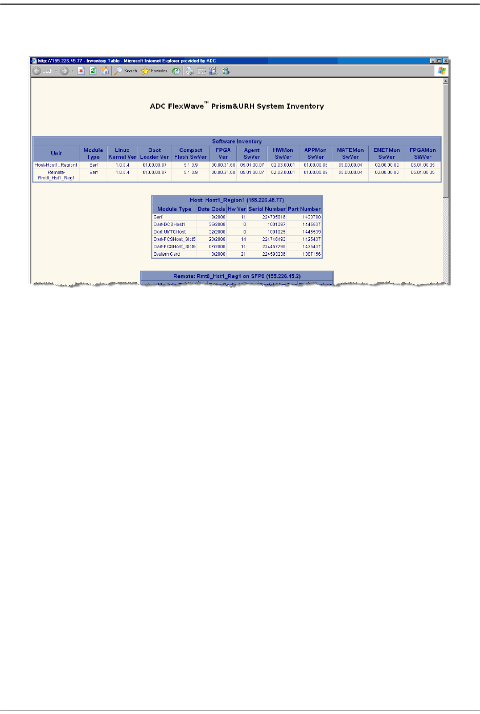
Working with the System Inventory
FlexWave Prism Host, Remote and EMS 5.1 System Reference Page 181
ADCP-77-073 • Issue 2 • 11/2009 © 2009 ADC Telecommunications, Inc.
7.3.1.1 System Inventory and Host Inventory Tables
Figure 7-1. System Inventory and Host Inventory Tables
The
System Inventory
table provides the following information:
•
Unit
—Host or Remote name
•
Module Type
—Host or Remote as listed in the row labeled as
Host
or
Remote
•
Linux Kernel Ver
—Version of the Linux Kernel on the Host or Remote
•
Boot Loader Ver
—Version of the Boot Loader on the Host or Remote
•
Compact Flash SwVer
—Version of the Compact Flash (Host or Remote, refer to the
row labeled for the Host or Remote). The version of the Compact Flash drives all
other software versions.
•
FPGA Ver
—Version of the FPGA on the Host or Remote SeRF (refer to the row
labeled for the Host or Remote)
•
Agent SwVer
—Version of the Agent on the Host or Remote (refer to the row labeled
for the Host or Remote)
•
HWMon SwVer
—Software Version of the Hardware Monitor process running on the
Host or Remote
•
APPMon SwVer
—Software Version of the Application Monitor process running on
the Host or Remote
•
MATEMon SwVer
—Software Version of the Mate Monitor process running on the
Host or Remote
•
ENETMon SwVer
—Software Version of the Ethernet Monitor process running on the
Host or Remote
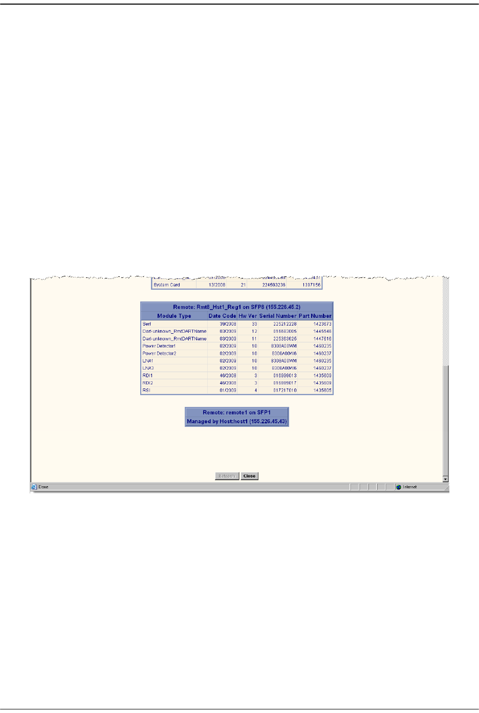
Using the EMS to Manage a Prism System
Page 182 FlexWave Prism Host, Remote and EMS 5.1 System Reference
© 2009 ADC Telecommunications, Inc ADCP-77-073 • Issue 2 • 11/2009
•
FPGAMon SWVer
—Software Version of the FPGA Monitor process running on the
Host or Remote
The
Host
table provides the following information:
•
Title
—Name of the Host in the format of
Host: HostName (xxx.xxx.xxx.xxx)
where:
–
HostName
is the default or user-assigned name for the Host
–
xxx.xxx.xxx.xxx
is the Host IP address
•
Module Type
—Type of module (such as SeRF, DART).
•
Date Code
—Date code for the module
•
Hw Ver
—Version of the module hardware
•
Serial Number
—Unique serial number for the module
•
Part Number
—ADC part number for the module
7.3.1.2 Remote Inventory Tables
Figure 7-2. Remote Inventories

Working with the System Inventory
FlexWave Prism Host, Remote and EMS 5.1 System Reference Page 183
ADCP-77-073 • Issue 2 • 11/2009 © 2009 ADC Telecommunications, Inc.
The
Remote Inventory
tables, of which there can be up to eight, comprise the following
information:
•
Title
—Name of the Remote in the format of
Remote: RemoteName (xxx.xxx.xxx.xxx)
,
where
–
RemoteName
is the default or user-assigned name for the Remote
–
xxx.xxx.xxx.xxx
is the Remote IP address
•
Module Type
—Type of module (such as LNA, SeRF, DART).
•
Date Code
—Date code for the module
•
Hw Ver
—Version of the module hardware
•
Serial Number
—Unique serial number for the module
•
Part Number
—ADC part number for the module
Using the EMS to Manage a Prism System
Page 184 FlexWave Prism Host, Remote and EMS 5.1 System Reference
© 2009 ADC Telecommunications, Inc ADCP-77-073 • Issue 2 • 11/2009
7.4 WORKING WITH PRISM SYSTEM NETWORK
INTERFACES
You use the EMS to configure the Prism system for one of the two different modes
listed below, which affects how you configure the network interface of the Network
and Craft ports and how you access the system through the EMS. In each mode, the
Host and its subtended Remotes require the same configuration. Both modes require
a DHCP server, which assigns an IP address to the Host and its subtended Remotes.
•
External Network
mode—is the default mode. The Host and subtended Remotes are
DHCP clients and expect IP addresses to be assigned by an external DHCP server
through a network Ethernet connector. If there is no external DHCP server, the
Host will not be able to communicate with any connected Remotes.
The Host Craft port has a DHCP server that you can use to communicate with the
Host directly. The IP address for the Host Craft port is 192.168.0.1. You can access
the EMS via the Craft port, but if the Network port is not connected to an external
DHCP server, the Remotes will not be visible to you.
•
Built-in Network
mode—
Built-In Network
mode is best suited for when there is no
network to connect to or if the Prism network does not have a DHCP server. In
Built-In Network mode, the functionality of the Network port and the Craft port
are swapped. You connect a laptop to the Host Network port, which is assigned a
default fixed IP address of 10.0.0.1 and all subtended network interfaces obtain a
DHCP address in this same subnet. Alternatively, in Built-In Network mode you
can connect the Craft port to an external DHCP server from which the Craft port
obtains its IP address.
Table 7-1 describes how the system mode affects the IP address for the Host and
subtended Remotes.
Static Mode—You also have the option of giving the devices on your Prism system static
IP addresses. Contact ADC for further information (see “Contacting ADC” on page 335).
There are potential problems in switching between the External Network and Built- In
Network modes. If cabled incorrectly your DHCP server could provide private IP
addresses on a public network. Set the Prism system mode once and then do not change
it.

Working with Prism System Network Interfaces
FlexWave Prism Host, Remote and EMS 5.1 System Reference Page 185
ADCP-77-073 • Issue 2 • 11/2009 © 2009 ADC Telecommunications, Inc.
Table 7-1. Prism System Modes and IP Addresses
Mode
Host IP Addresses Remote IP Addresses
Craft Port Network Port Craft Port Network Port
External Network
DHCP server
assigns IP
addresses in the
192.168.0.x range.
For direct access
to the Host
through the EMS,
in a Web browser
enter the IP
address
192.168.0.1
(http://192.168.0.
1)
The Host Network
port is a DHCP
client and must be
connected to a
network with a
DHCP server to
obtain an IP
address.
For direct access
to the Host
through the EMS,
in a Web browser
enter the IP
address assigned
by the DHCP
server. For
information on
discovering the IP
address, see the
DHCP server or
connect to the EMS
using the craft
port and bring up
the System View.
Remote Craft port
IP address is
192.168.0.1.
However, you
cannot get direct
access to the Host
or the network
from the Remote
Craft port. You get
read-only view to
Remote
configuration.
The Remote
network port
obtains its IP
address from the
external DHCP
server.
You can reach the
Remote via telnet
or ssh from the
Host.
Built-In Network
DHCP client must
be connected to a
network with a
DHCP server to
obtain an IP
address. The IP
address can then
be used by HTTP
and SNMP to
connect to the
Host.
The Network port
is a DHCP server
with a fixed IP
address of
10.0.0.1 and
assigns IP
addresses in the
10.0.0.x range to
subtended
Remotes.
For direct access
to the Host
through the EMS,
in a Web browser
enter the IP
address
10.0.0.1
(http://10.0.0.1)
Remote Craft port
IP address is
192.168.0.1.
However, you
cannot get direct
access to the Host
or the network
from the Remote
Craft port. You get
read-only view to
Remote
configuration.
The Remote
Network port is a
LAN/WAN
connection to the
network to which
the Host Network
port is connected.
The Remote
Network port
therefore obtains
an IP address in
the 10.0.0.x range
from the DHCP
server in the Host.
You can reach the
Remote via telnet
or ssh from the
Host.
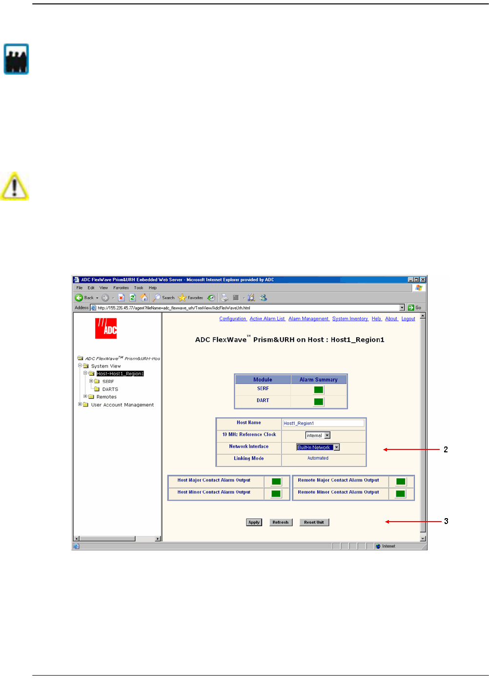
Using the EMS to Manage a Prism System
Page 186 FlexWave Prism Host, Remote and EMS 5.1 System Reference
© 2009 ADC Telecommunications, Inc ADCP-77-073 • Issue 2 • 11/2009
7.4.1 Changing to Built-In Network Mode
Built-In Network
mode allows all Remotes to be assigned an IP address to allow
communication without the need for an external DHCP router. You therefore set the
Prism system to
Built-In Network
mode if there is no network to connect to or if the
network does not have a DHCP server. You would also change the Prism system to
Built-In Network
mode if you intend to transition to static IP addresses.
11 To open the
Host Summary
view in the EMS View Frame, in the Function Explorer
Tree select
System View
, and then click on the Host name node.
22 Set
Network Interface
to
Built-In Network
. This sets the Network port on the Host to
the IP address 10.0.0.1 and starts a DHCP server on the Host that will provide IP
addresses to connected Remotes. Built-In Network mode also causes the Host
Craft port to run a DHCP client instead of using the IP address 192.168.0.1.
33 Click
Apply
.
Only a user logged in under the admin or a Network Manager account can change Prism
settings through the EMS.
When changing from External Network mode to Built- In Network mode, if the Prism
system is cabled incorrectly, the Prism DHCP server could broadcast private IP
addresses on a public network. You should therefore only change the mode once,
preferably during setup.
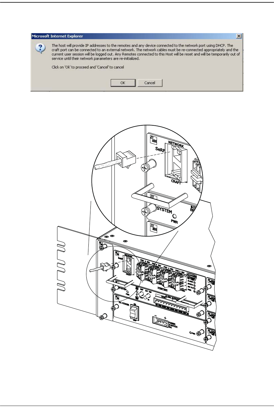
Working with Prism System Network Interfaces
FlexWave Prism Host, Remote and EMS 5.1 System Reference Page 187
ADCP-77-073 • Issue 2 • 11/2009 © 2009 ADC Telecommunications, Inc.
44 In the confirmation dialog, click
OK
. Your current EMS session will close down as
the IP addressing and configuration will have been modified.
55 Disconnect the Ethernet cable from the Host Craft port and connect it to the Host
Network port.
22403-A
RJ-45
CONNECTOR
DETAIL

Using the EMS to Manage a Prism System
Page 188 FlexWave Prism Host, Remote and EMS 5.1 System Reference
© 2009 ADC Telecommunications, Inc ADCP-77-073 • Issue 2 • 11/2009
66 Connect the free end of the Ethernet cable to the computer’s port. Leave your
computer in DHCP mode. It will automatically receive an IP address in the
10.0.0.0/24 subnet from the Host Network port.
77 Open a Web browser and in its URL field, enter the Host IP address: 10.0.0.1
88 When the
Connect to
dialog opens:
aa Enter the
User name
provided by ADC or by the Network Administrator. The
default is admin.
bb Enter the
Password
provided by ADC or by the Network Administrator. The
default is adc123.
99 Click
OK
. The
Welcome to ADC FlexWave Prism Embedded Web Server
page opens.
7.4.2 EMS Access Methods
The FlexWave EMS has four access methods that are listed below and as shown and
numbered in Figure 7-3.
11 A laptop subtended to the Craft port on the Host provides direct access to the
EMS. In this scenario the Host and the Remote can be configured and monitored
through the EMS. This is the default access scenario during initial configuration
and commissioning as described in “Access the EMS” on page 144.
22 A personal computer with a Web browser connected through the internet or
intranet to the Network port on the Host. This method provides a remote user
access to the EMS through a Local Area Network (LAN) or Wide Area Network
(WAN). In this scenario the Host and subtended Remotes can be configured and
monitored through the EMS. After initial system setup, this is the default access
method.
33 A personal computer with a Web browser connected to the Network port on the
Remote provides a remote user a LAN connection to the Host network interface,
which provides access to the EMS. See “Accessing the EMS Through the Remote
Network Port” on page 189.
It can take a while for the system to update the interfaces (can be up to 30 minutes, but
typically is no more than 10 minutes). If the Remotes already have a DHCP IP address
from an external network and you change it to built- in (in a different subnet), it can take
30 minutes for the Remote to request an update from an external IP address to the
10.0.0.x IP address. During this transient period, there will not be communication with
the Remotes.
The Host will also take awhile to change from an external IP address to the 10.0.0.1 Ip
address, so a period of no communication with the Host can be expected as well.
EMS Access Methods 1 and 2 are true for the default External Network mode described
in this chapter. If your Prism system is set to Built- in Network mode, then the
definitions for EMS Access Methods 1 and 2 for the Host Network and Craft ports are
are switched.
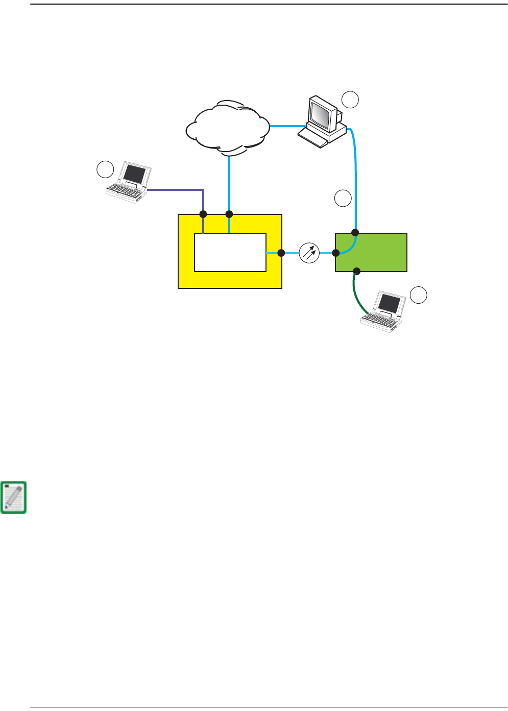
Working with Prism System Network Interfaces
FlexWave Prism Host, Remote and EMS 5.1 System Reference Page 189
ADCP-77-073 • Issue 2 • 11/2009 © 2009 ADC Telecommunications, Inc.
44 A laptop subtended to the Remote Craft port provides access to the EMS. In this
scenario, Remote configuration interfaces can be viewed in Read-Only format. The
Host configuration interfaces are disabled and cannot be viewed. See “Accessing
the EMS Through the Remote Craft Port” on page 192.
Figure 7-3. Four Points of EMS Access
7.4.2.1 Accessing the EMS Through the Remote Network Port
The Remote provides a Network port allowing communications with the internal
processor and transfer of service data to the optical protocol allowing IP servicing
between the Host and Remote(s). This port is customer accessible for monitoring the
interface with the subtended Host and ENET subtended devices at the Remote. The
Network port is 10/100/1000 BASE-T MDI and requires a minimum of CAT 5 cable.
The network cable must be terminated with a hardened RJ-45 male connector for
connection to the Network port. The maximum cable length is 300 feet (91.4 m).
Use the following procedure to install the Network cable and then log in to the EMS.
Although the Network port on the Remote is a GigE port, the available bandwidth is only
100Mbps (part of this bandwidth is used for system management services).
You cannot dedicate a full 100Mbps of bandwidth for external ethernet services off the
Remote’s Network port. For example, if connecting a WiFi access point to the Remote’s
Network port, you need to reduce the available bandwidth to less than 100Mbps (such
as, 50Mbps).
Host Unit
with EMS
Craft port Network port
Network port
IP
IP
IP
IP
2
Network
(LAN or WAN)
1
3
4
Remote
Unit
Craft port
75356-04
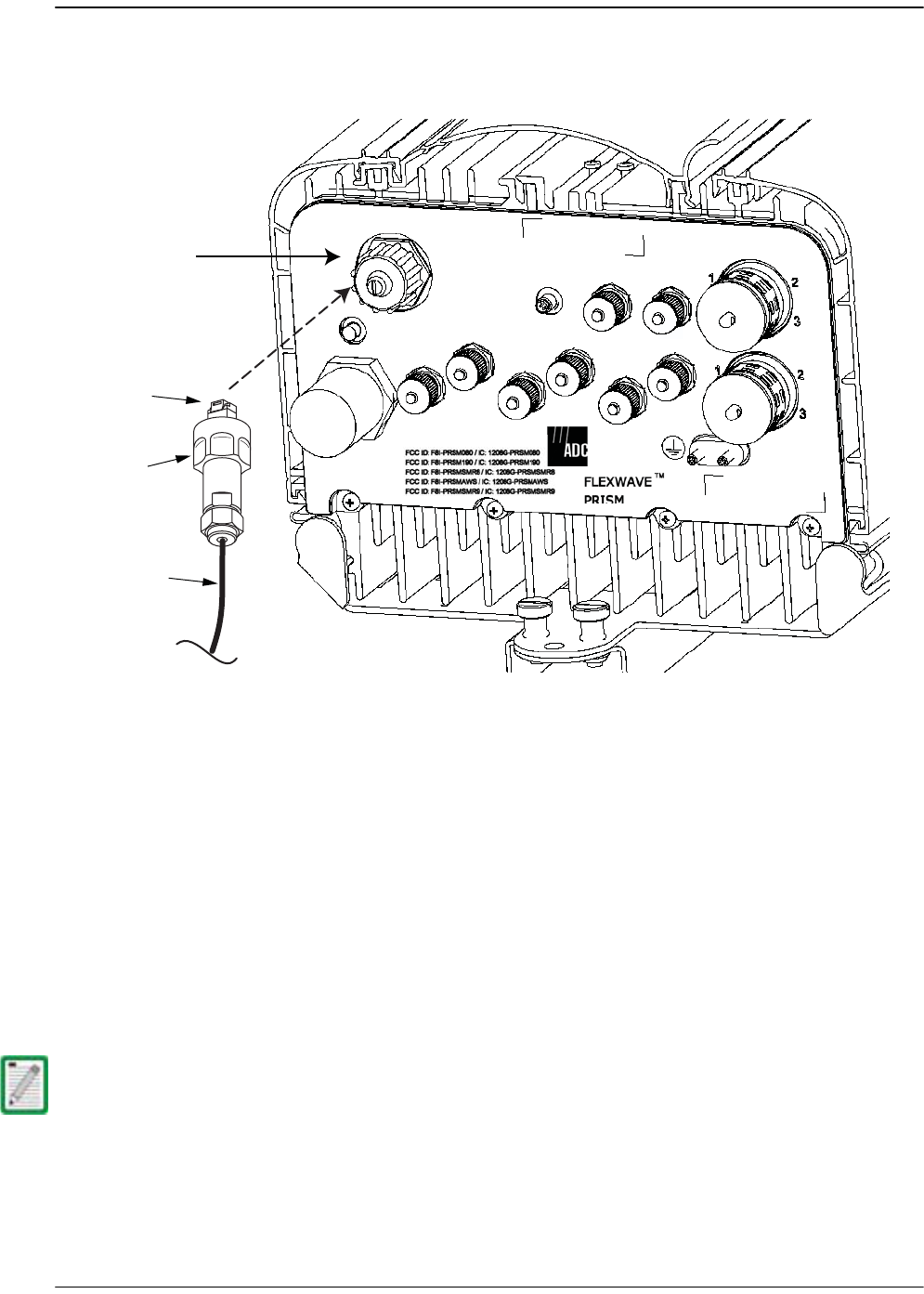
Using the EMS to Manage a Prism System
Page 190 FlexWave Prism Host, Remote and EMS 5.1 System Reference
© 2009 ADC Telecommunications, Inc ADCP-77-073 • Issue 2 • 11/2009
11 Remove the dust cap from the RJ-45 connector located at the bottom of the
Remote as shown below.
22 Route the network cable from the network connection to the underside of the
Remote.
33 Align the plug end of the RJ-45 cable connector with the RJ-45 port receptacle and
then insert the cable plug into the port receptacle.
44 Slide the connector nut up to the port until it engages the connector locking
mechanism.
55 Tighten the connector nut in a clockwise direction (if necessary, use a wrench or
pliers to grip the connector nut) until it snaps past the indented position and
locks into place. It may be necessary to apply 30 to 50 in-lbs (3.4 to 5.6 Nm) of
torque to the connector nut in order to turn it past the indented position.
It may be necessary to apply 30 to 50 lbs/force- inches (3.4 to 5.6 Nm) of torque to the
connector nut in order to turn it past the indented position.
NETWORK
AUX.
MOD A
RX1
MOD A
TX0/RX0
FIBER 1
FIBER 2
MOD B
TX0/RX0
MOD B
RX1
MOD C
TX0/RX0
MOD D
TX0/RX0
MOD C
RX1
MOD D
RX1
POWER
100-240 VAC
50-60 Hz
16 AMPS
RJ-45 Network
Connector port
Network cable
Connector nut
RJ-45 plug
Bottom View
77073-010

Working with Prism System Network Interfaces
FlexWave Prism Host, Remote and EMS 5.1 System Reference Page 191
ADCP-77-073 • Issue 2 • 11/2009 © 2009 ADC Telecommunications, Inc.
66 Connect your computer and start a Web browser.
77 In the URL field for the Web browser, enter the IP address of the EMS Host:
•• If the Prism system is set to
External Network
mode, enter IP Address obtained
from the DHCP server. (Your computer also receives an IP address from the
external DHCP server connected to the Host.
•• If the Prism system is set to
Built-In Network
mode, enter 10.0.0.1 . (The
Remote Network port is a LAN extension from the Host Network port. Your
computer receives an IP address in the 10.0.0.0/24 subnet from the Host.)
88 When the
Connect to
dialog opens:
aa Enter the
User name
provided by ADC or by the Network Administrator. The
default is admin.
bb Enter the
Password
provided by ADC or by the Network Administrator. The
default is adc123.
99 Click
OK
. The
Welcome to ADC FlexWave Prism Embedded Web Server
page opens.
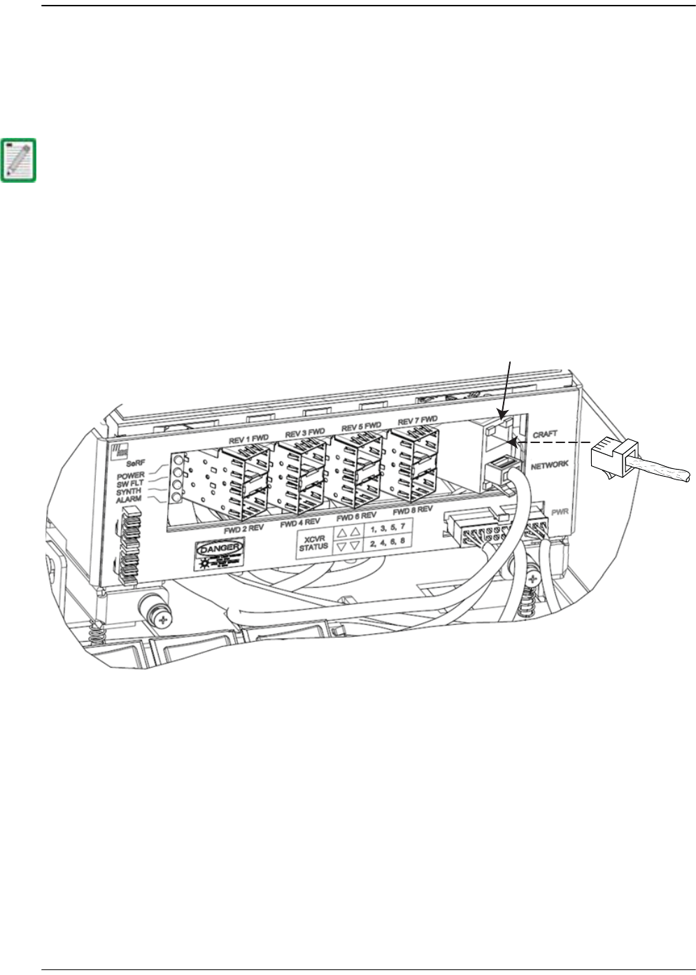
Using the EMS to Manage a Prism System
Page 192 FlexWave Prism Host, Remote and EMS 5.1 System Reference
© 2009 ADC Telecommunications, Inc ADCP-77-073 • Issue 2 • 11/2009
7.4.2.2 Accessing the EMS Through the Remote Craft Port
You can use the Craft port on the SeRF Module to access the FlexWave EMS to view
system configuration and alarms. For example, if there is a problem communicating
with the Remote and you have determined that fiber is not the issue, connecting to
the Craft port helps you obtain beneficial troubleshooting information.
11 Verify that your PC network interface is configured for DHCP.
22 If you have a wireless network interface, disable it. Otherwise an IP conflict may
result if the wireless network resides in the same IP subnet as the Craft port.
33 Open the Prism door.
44 Remove the dust cap from the Craft port located on the SeRF Module.
When you access the EMS through the Remote Craft port, the EMS GUI shows only the
Remote in its Function Explorer Tree. You cannot configure any system components or
clear alarms.
77073-025
RJ-45 Craft port
RJ-45
Connector

Working with Prism System Network Interfaces
FlexWave Prism Host, Remote and EMS 5.1 System Reference Page 193
ADCP-77-073 • Issue 2 • 11/2009 © 2009 ADC Telecommunications, Inc.
55 Use an Ethernet CAT 5 cable with RJ-45 connectors to connect a laptop to the Craft
port.
66 Connect your computer and start a Web browser.
77 Verify that the laptop is receiving an IP address in the 192.168.0.0/24 subnet (that
is, 192.168.0.100 or 192.168.0.99 and so forth).
88 In the URL field for the Web browser, enter the IP address of the Craft port
(defaults to 192.168.0.1).
99 When the
Connect to
dialog opens enter viewer in the
User name
box and in the
Password
box.
100 Click
OK
. The
Welcome to ADC FlexWave Prism Embedded Web Server
page opens.
The user name (viewer) and password (viewer) used to access the EMS through the
Remote Craft port cannot be changed.

Using the EMS to Manage a Prism System
Page 194 FlexWave Prism Host, Remote and EMS 5.1 System Reference
© 2009 ADC Telecommunications, Inc ADCP-77-073 • Issue 2 • 11/2009
Intentionally Blank Page

FlexWave Prism Host, Remote and EMS 5.1 System Reference Page 195
ADCP-77-073 • Issue 2 • 11/2009 ©2009 ADC Telecommunications, Inc.
8MANAGING USER ACCOUNTS
8.1 FlexWave EMS User Accounts.............................................................................196
8.2 Viewing User Accounts ......................................................................................197
8.3 Adding a User Account ......................................................................................198
8.4 Changing a User Access Level ............................................................................202
8.5 Changing the Password of Another User ..............................................................206
8.6 Changing Your Own Password ............................................................................208
8.7 Deleting a User Account ....................................................................................210
Content Page

Managing User Accounts
Page 196 FlexWave Prism Host, Remote and EMS 5.1 System Reference
© 2009 ADC Telecommunications, Inc ADCP-77-073 • Issue 2 • 11/2009
8.1 FLEXWAVE EMS USER ACCOUNTS
The EMS provides security, which can be broadly classified as:
•
User Authentication
, which defines the way a user is identified prior to being
allowed to log on to the EMS. User Authentication ensures that only known users
have access by providing a method of identifying each user through a user ID and
password.
•
User Authorization
, which involves managing the user’s privileges in the Prism
network management infrastructure. Authorization is based on the concept of
user access system configuration restrictions.
There are three user-access levels that can be assigned by the admin:
•• admin—the default user account that has unrestricted access to all EMS user
accounts and management capabilities. To protect against unauthorized access to
the Prism network, the user assigned the admin role should follow the process
described in “Changing Your Own Password” on page 208 to change the password
for the admin user account.
•• Network Manager—has read and write access to all system functions except user
account management.
•• Network User—has read only permissions into the system.
There are also two default user-access levels for the Remote that cannot be deleted
or changed:
•• Operator—has Read and Write access to only the Prism Remote functions, all
other operations are Read Only. (This user is not available on URH Remotes.)
•• Viewer—has Read Only rights for Prism and URH Remotes.
FlexWave EMS prevents a login in which the user enters an invalid User ID or
password.
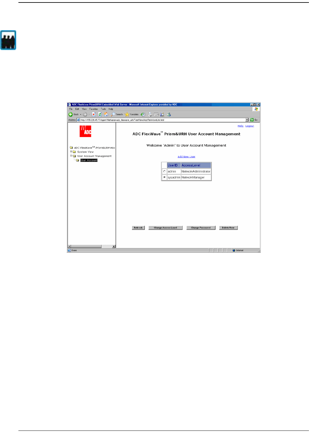
Viewing User Accounts
FlexWave Prism Host, Remote and EMS 5.1 System Reference Page 197
ADCP-77-073 • Issue 2 • 11/2009 © 2009 ADC Telecommunications, Inc.
8.2 VIEWING USER ACCOUNTS
In the Function Explorer Tree, click on
User Account Management, User Account
to open
the
User Account Management
view in the EMS View Frame with a table that lists all
current user accounts.
The
User Account Management
view has the following elements:
•
Add New User
link—Opens the
Add New User
dialog (see “Adding a User Account”
on page 198).
•• Select radio button—Selects the user whose account the admin wants to manage.
•
UserID
column—Lists users by the User ID entered into the EMS by the admin.
•
AccessLevel
column—identifies the user’s access level.
•
Refresh
button—updates the
User Account Management
view
•
Change Access Level
button—opens the
Change Access Level
window (see “Changing
a User Access Level” on page 202).
•
Change Password
button—opens the
Change Password Settings
view (“Changing the
Password of Another User” on page 206)
•
Delete User
button—allows the admin to delete a user account (see “Deleting a User
Account” on page 210).
Only a user logged in under the admin account can view all existing user accounts.
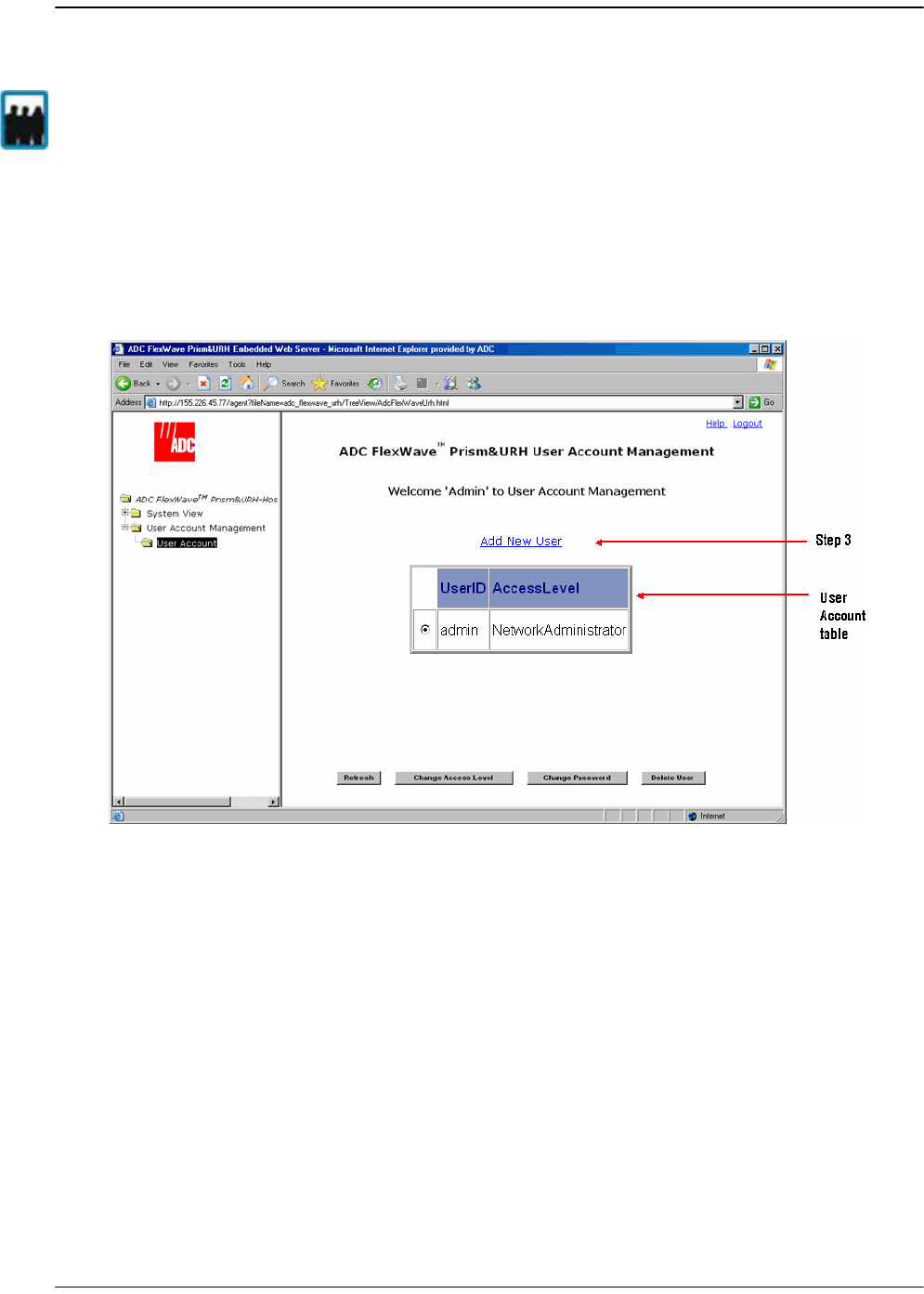
Managing User Accounts
Page 198 FlexWave Prism Host, Remote and EMS 5.1 System Reference
© 2009 ADC Telecommunications, Inc ADCP-77-073 • Issue 2 • 11/2009
8.3 ADDING A USER ACCOUNT
The FlexWave EMS limits the number of users to 50.
11 In the Function Explorer Tree, click on
User Account Management, User Account
to
open the
User Account Management
view in the EMS View Frame with a table that
lists all current user accounts.
Only a user logged in under the admin account can add user accounts.
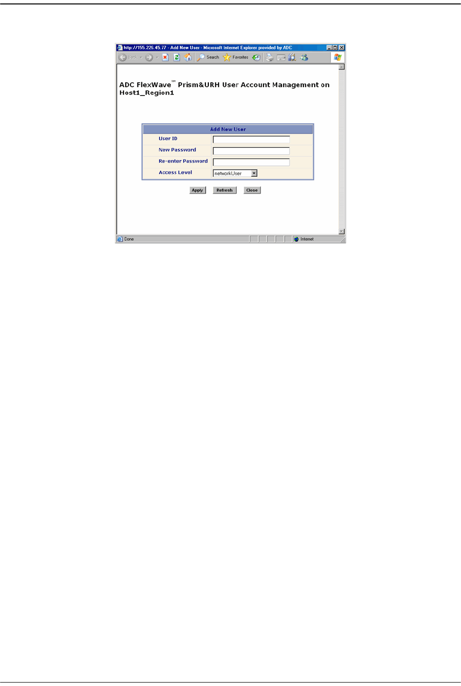
Adding a User Account
FlexWave Prism Host, Remote and EMS 5.1 System Reference Page 199
ADCP-77-073 • Issue 2 • 11/2009 © 2009 ADC Telecommunications, Inc.
22 Click on
Add New User
to open the
Add New User
dialog.
33 Verify that the Host name in the
User Account Management
view heading is correct.
In the graphic above, a user account will be added to
Host1_Region1
.
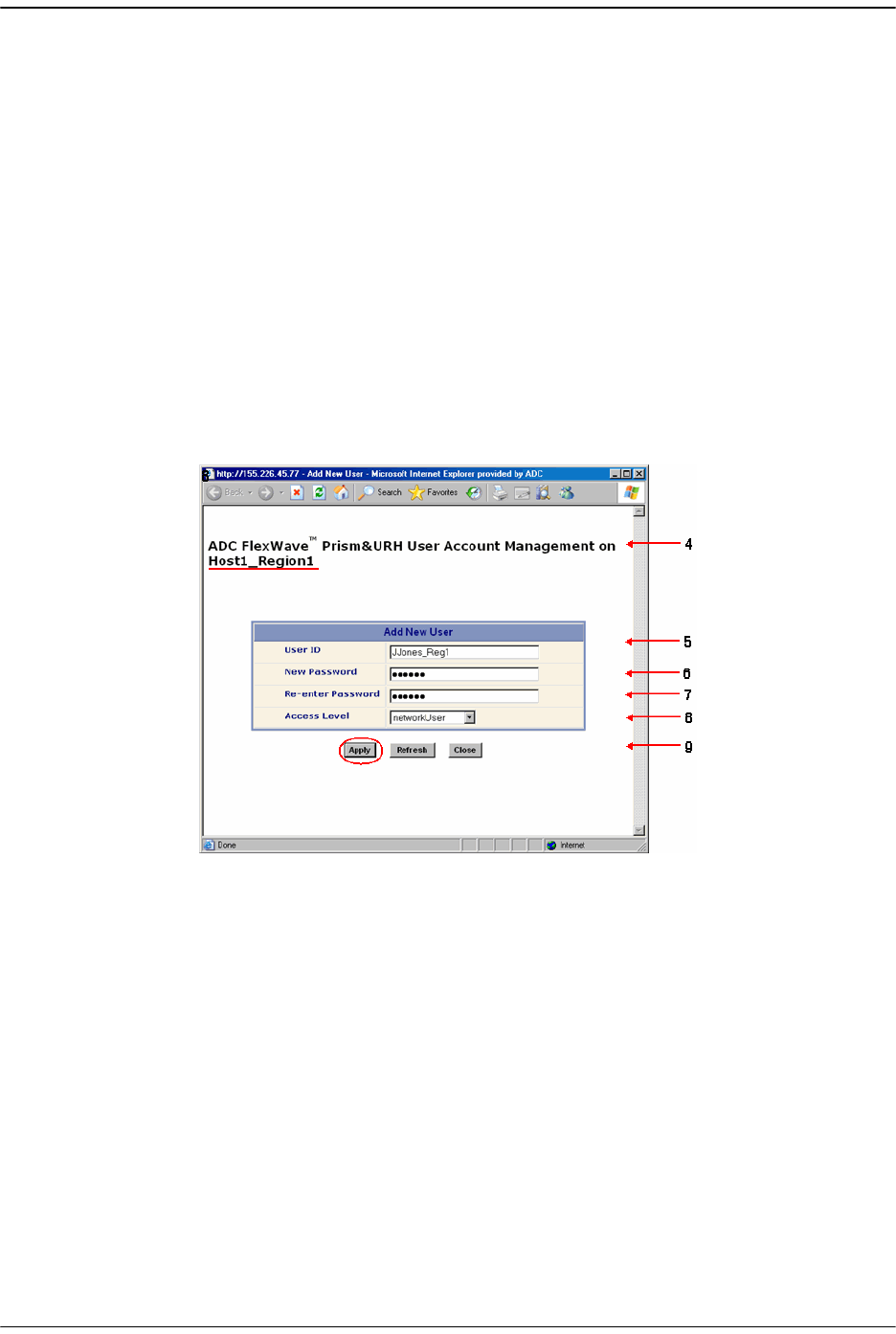
Managing User Accounts
Page 200 FlexWave Prism Host, Remote and EMS 5.1 System Reference
© 2009 ADC Telecommunications, Inc ADCP-77-073 • Issue 2 • 11/2009
44 In the
User ID
box, type a name by which the user can be identified. No less than 5
or more than 32 characters may be entered. No spaces are allowed. The only
special character allowed is an underscore, which cannot be the first character of
the name. Numerals are allowed, but cannot be the first character of the name.
55 In the
New Password
box, create a password for the new user. A password must be
between 6 and 12 alphanumeric characters and cannot contain spaces.
66 In the
Re-enter Password
box, retype the new user’s password.
77 In the
Access Level
list, select the security level for the user. The system supports
only one Network Administrator (admin) account, so the new user
Access Level
can
therefore only be one of the following:
•
networkManager
—assigns the role of Network Manager, which provides read
and write access to all system functions except user account management.
•
networkUser
—assigns the role of Network User, which provides read only
permission.
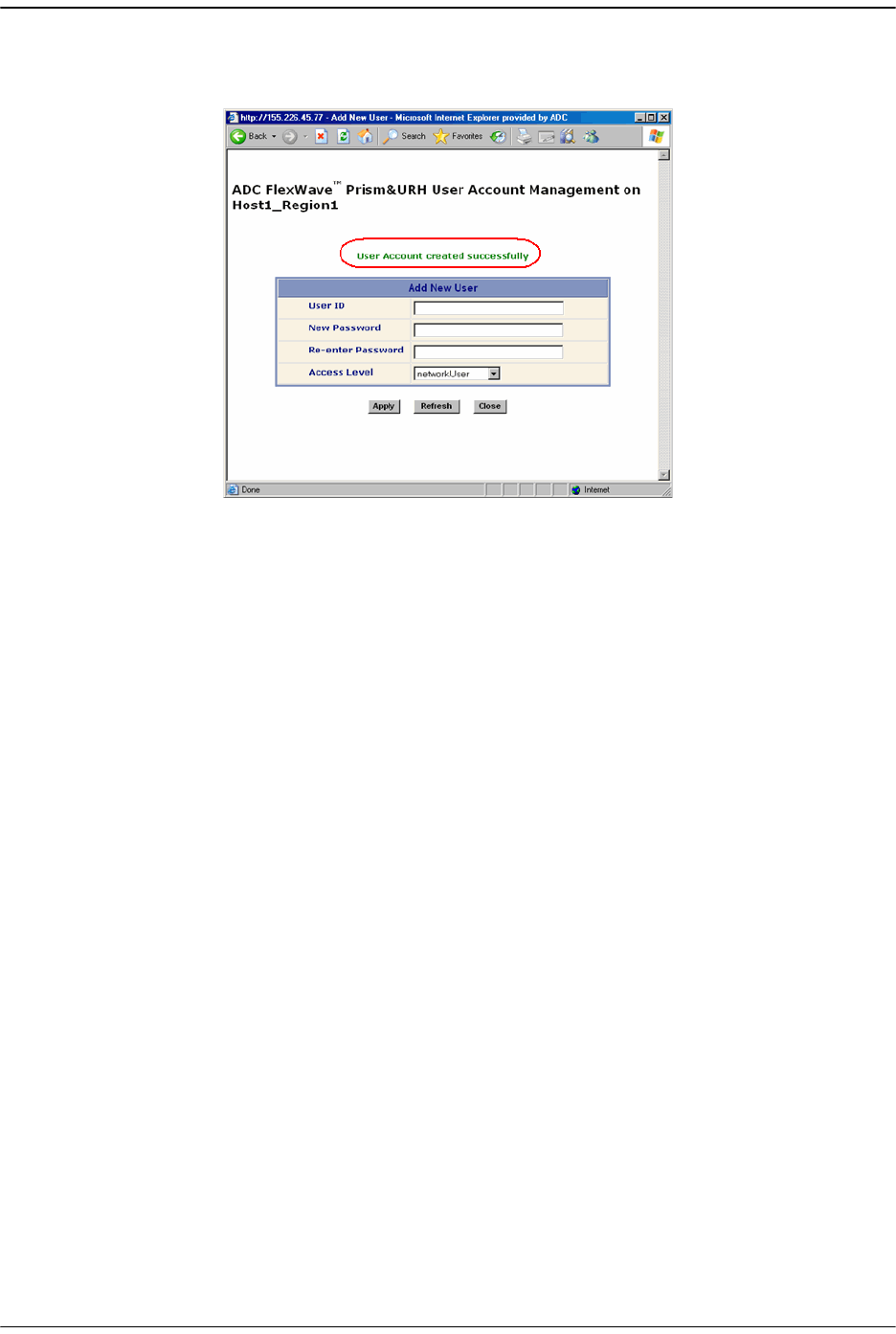
Adding a User Account
FlexWave Prism Host, Remote and EMS 5.1 System Reference Page 201
ADCP-77-073 • Issue 2 • 11/2009 © 2009 ADC Telecommunications, Inc.
88 Click
Apply
. The
User Account created successfully
message displays and the
Add New
User
panel is cleared so you can add another user.
99 Do one of the following:
•• Follow Steps 5 - 9 to create another user account.
•• Click
Close
to close the
Add New User
dialog.
100 In the
User Account Management
view, click
Refresh
to display the newly added
user(s).

Managing User Accounts
Page 202 FlexWave Prism Host, Remote and EMS 5.1 System Reference
© 2009 ADC Telecommunications, Inc ADCP-77-073 • Issue 2 • 11/2009
8.4 CHANGING A USER ACCESS LEVEL
11 In the Function Explorer Tree, click on
User Account Management, User Account
to
open the
User Account Management
view in the EMS View Frame with a table that
lists all current user accounts.
22 Click the radio button that corresponds to the user whose account is to be edited.
Only a user logged in under the admin account can change a user Access Level.
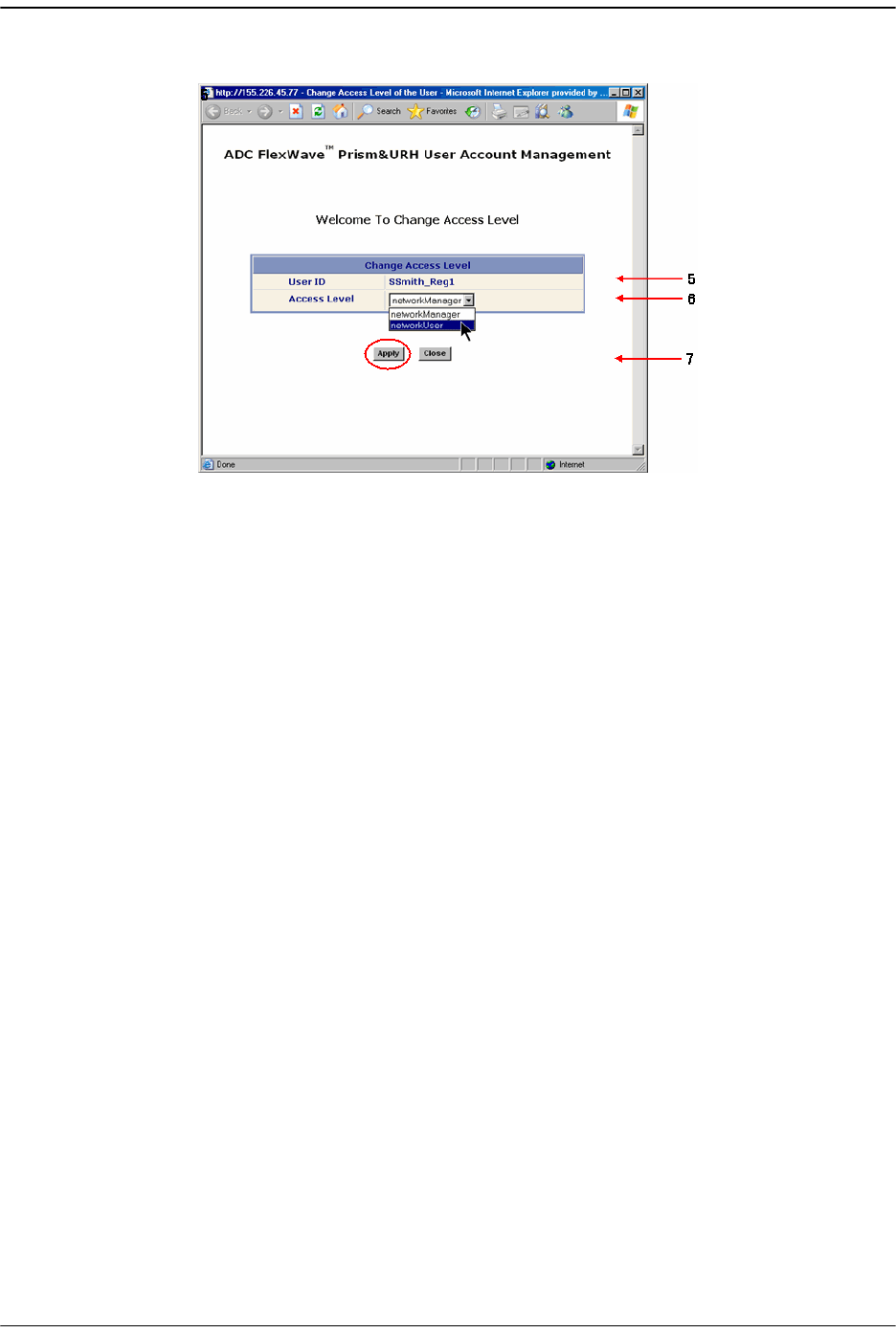
Changing a User Access Level
FlexWave Prism Host, Remote and EMS 5.1 System Reference Page 203
ADCP-77-073 • Issue 2 • 11/2009 © 2009 ADC Telecommunications, Inc.
33 Click
Change Access Level
to open the
Change Access Level
window.
44 Verify that the correct user is listed in the
User ID
field.
55 Select a new access level. The system has three access levels, but supports only
one admin (Network Administrator) account. The revised user
Access Level
can
therefore only be one of the following:
•
networkManager
—has read and write access to all system functions except user
account management.
•
networkUser
—has read only permissions into the system.
66 Click
Apply
.
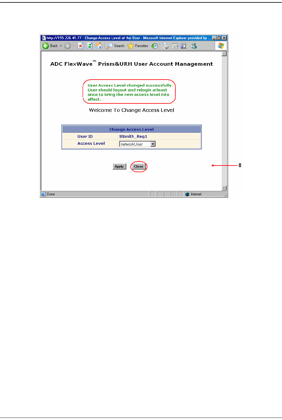
Managing User Accounts
Page 204 FlexWave Prism Host, Remote and EMS 5.1 System Reference
© 2009 ADC Telecommunications, Inc ADCP-77-073 • Issue 2 • 11/2009
The
User Account Management
window opens showing the new Access Level and
stating that the Access Level has been changed.
77 In the
Change Access Level
window, click
Close
.
88 In the
User Account Management
view, click
Refresh
.
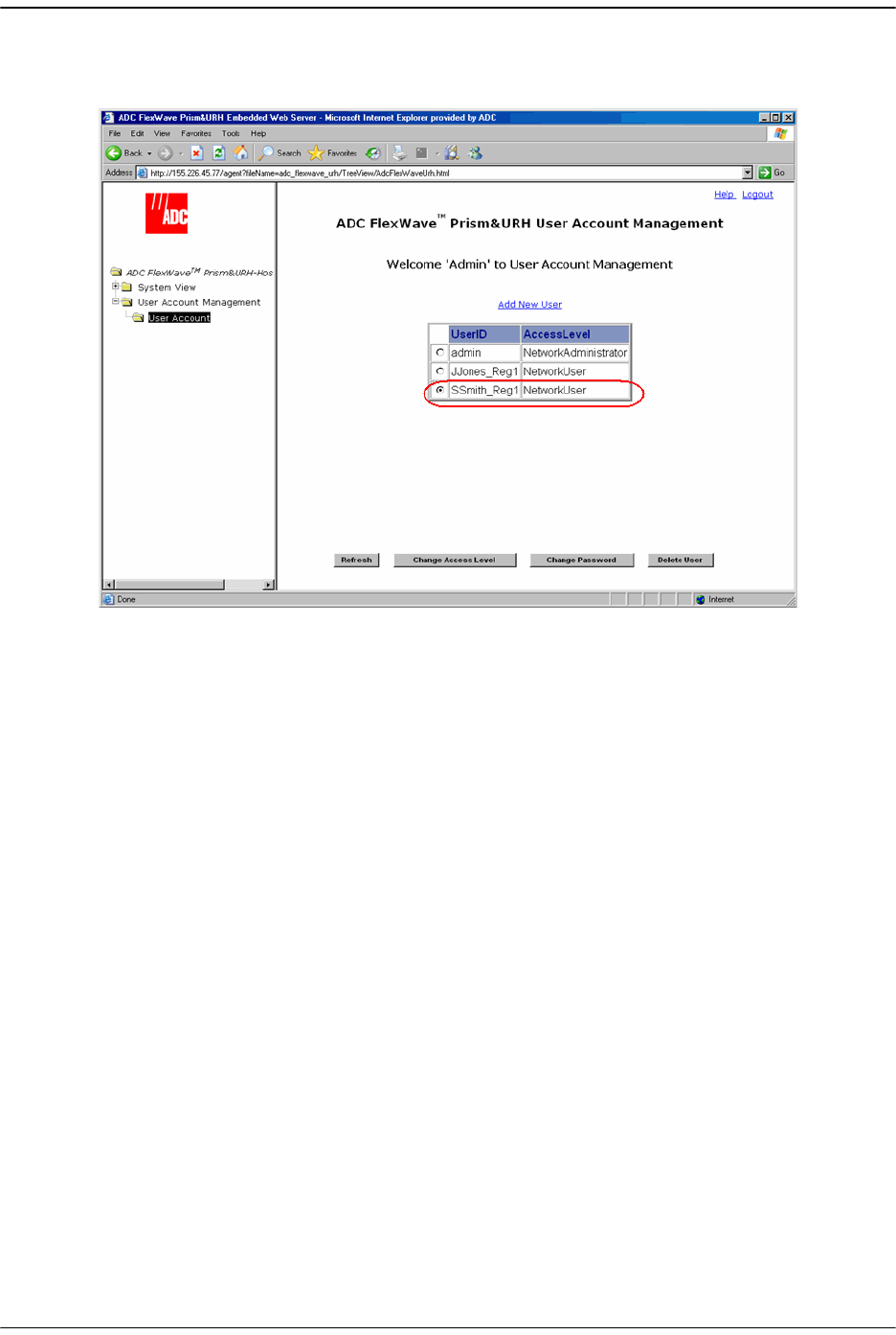
Changing a User Access Level
FlexWave Prism Host, Remote and EMS 5.1 System Reference Page 205
ADCP-77-073 • Issue 2 • 11/2009 © 2009 ADC Telecommunications, Inc.
The new access level assigned to the user is listed in the
AccessLevel
column that
corresponds to the
UserID
.
99 If the user was logged on to the system during this procedure, the user needs to
log off and then log back on again to put the new access level into effect.
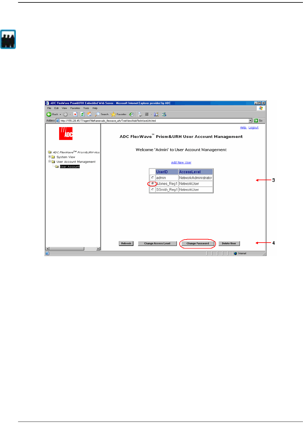
Managing User Accounts
Page 206 FlexWave Prism Host, Remote and EMS 5.1 System Reference
© 2009 ADC Telecommunications, Inc ADCP-77-073 • Issue 2 • 11/2009
8.5 CHANGING THE PASSWORD OF ANOTHER USER
11 In the Function Explorer Tree, click on
User Account Management, User Account
to
open the
User Account Management
view in the EMS View Frame with a table that
lists all current user accounts.
22 Click the radio button that corresponds to the user account for which you want
to change the password.
33 Click
Change Password
to open the
Change Password Settings
window.
Only a user logged in under the admin account can change the password for another
user. All users can change their own password (see “Changing Your Own Password” on
page 208).
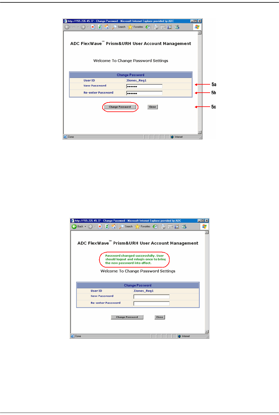
Changing the Password of Another User
FlexWave Prism Host, Remote and EMS 5.1 System Reference Page 207
ADCP-77-073 • Issue 2 • 11/2009 © 2009 ADC Telecommunications, Inc.
44 In the
Change Password Settings
window, do the following:
aa In the
New Password
box, type a new password. A password must be between 6
and 12 alphanumeric or special characters, but cannot contain spaces.
bb In the
Re-enter Password
box, retype the new password.
cc Click
Change Password
.
The password changed successfully message displays:
55 Click
Close
to close the
Change Password Settings
window.
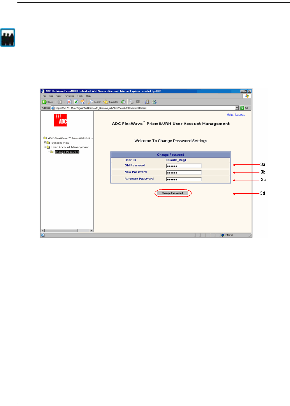
Managing User Accounts
Page 208 FlexWave Prism Host, Remote and EMS 5.1 System Reference
© 2009 ADC Telecommunications, Inc ADCP-77-073 • Issue 2 • 11/2009
8.6 CHANGING YOUR OWN PASSWORD
11 In the Function Explorer Tree, select
User Account Management, Change Password
to
open the
Change Password Settings
view in the EMS View Frame.
22 Do the following in the
Change Password Settings
view:
aa In the
Old Password
box, type your current password.
bb In the
New Password
box, type the new password. A password must be between
6 and 12 alphanumeric or special characters, but cannot contain spaces.
cc In the
Re-enter Password
box, retype the new password.
dd Click
Change Password
.
All users can change their own password. Only a user logged in under the admin account
can change the password for another user (see “Changing the Password of Another
User” on page 206).
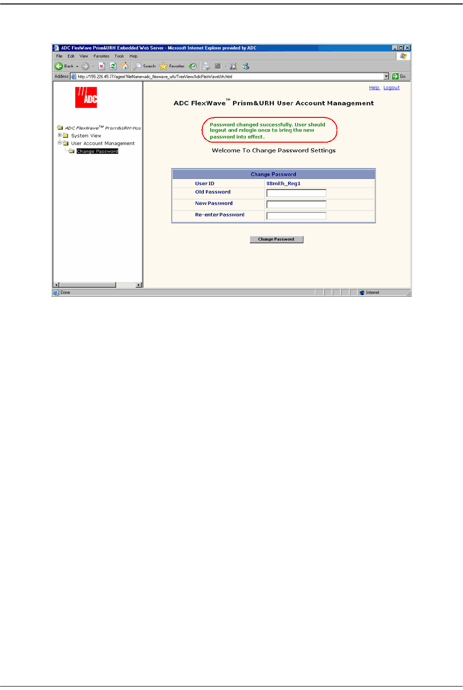
Changing Your Own Password
FlexWave Prism Host, Remote and EMS 5.1 System Reference Page 209
ADCP-77-073 • Issue 2 • 11/2009 © 2009 ADC Telecommunications, Inc.
The password changed successfully message displays:
33 Log out of the EMS and then log back in to set your new password.
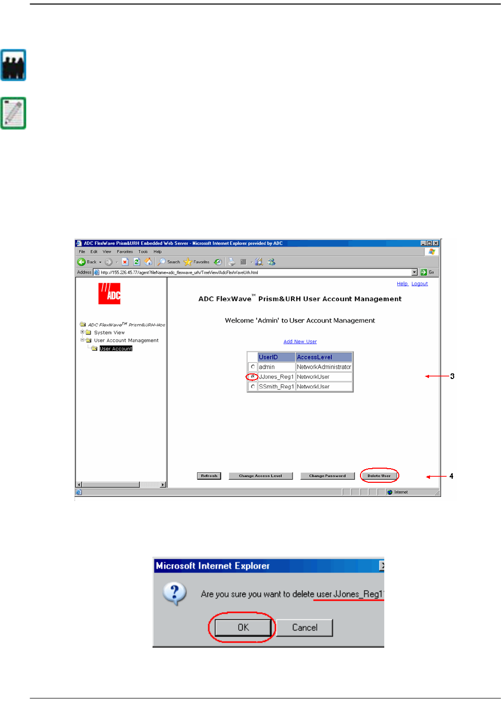
Managing User Accounts
Page 210 FlexWave Prism Host, Remote and EMS 5.1 System Reference
© 2009 ADC Telecommunications, Inc ADCP-77-073 • Issue 2 • 11/2009
8.7 DELETING A USER ACCOUNT
11 In the Function Explorer Tree, click on
User Account Management, User Account
to
open the
User Account Management
view in the EMS View Frame.
22 Click the radio button that corresponds to the user account to be deleted.
33 Click
Delete User
.
44 In the confirmation dialog, verify that you selected the correct user to delete, and
then click
OK
.
Only a Network Administrator can delete a user account.
The default Network Administrator account with the User ID of admin cannot be deleted.
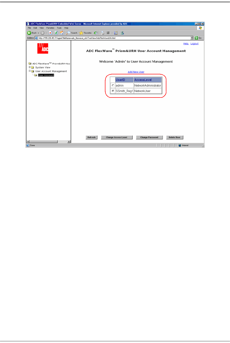
Deleting a User Account
FlexWave Prism Host, Remote and EMS 5.1 System Reference Page 211
ADCP-77-073 • Issue 2 • 11/2009 © 2009 ADC Telecommunications, Inc.
The user account is removed from the EMS.

Managing User Accounts
Page 212 FlexWave Prism Host, Remote and EMS 5.1 System Reference
© 2009 ADC Telecommunications, Inc ADCP-77-073 • Issue 2 • 11/2009
Intentionally Blank Page