ADC Telecommunications PRSM074C FlexWave™ Prism - 40 Watt 700 Upper C - Band User Manual 77073
ADC Telecommunications Inc FlexWave™ Prism - 40 Watt 700 Upper C - Band 77073
Contents
- 1. Prism Brochure
- 2. Manual part 1
- 3. Manual part 2
- 4. Manual part 3
Manual part 3

FlexWave Prism Host, Remote and EMS 5.1 System Reference Page 213
ADCP-77-073 • Issue 2 • 11/2009 ©2009 ADC Telecommunications, Inc.
9MANAGING HOST UNITS
9.1 Viewing the Host Summary................................................................................214
9.2 Resetting the Host Unit .....................................................................................215
9.3 Viewing Host SeRF Ethernet Ports.......................................................................217
9.4 Decommissioning a DART in a Host.....................................................................220
9.5 Viewing the Host SeRF Summary........................................................................222
9.6 Viewing Host SeRF Optical Ports.........................................................................224
9.7 Viewing Host DART Alarms ................................................................................226
Content Page
Managing Host Units
Page 214 FlexWave Prism Host, Remote and EMS 5.1 System Reference
© 2009 ADC Telecommunications, Inc ADCP-77-073 • Issue 2 • 11/2009
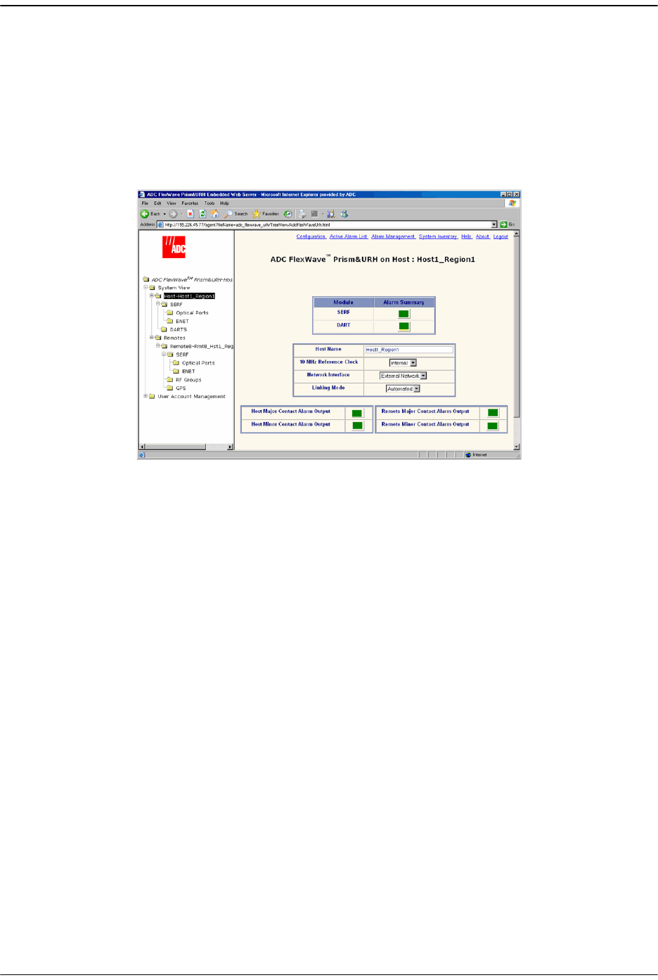
9.1 VIEWING THE HOST SUMMARY
This section describes the read-only status indicators in the Host Summary view. For
information on setting Host attributes, see “Enter a Host Name, Clock Source, and
Linking Mode” on page 147 and “Changing to Built-In Network Mode” on page 186.
To open the
Host Summary
view in the EMS View Frame, in the Function Explorer Tree
select
System View
, and then click on the Host name node.
The read-only status indicators are:
•
SERF
—Current summary alarm state of Host SeRF card. Red indicates that a major
alarm exists for some component module of the SeRF. Yellow indicates a minor
alarm.
•
DART
—Current summary alarm state is indicated by status indicator on same row
of page. Red indicates that a major alarm exists for the DART. Yellow indicates a
minor alarm.
•
Host Major Contact Alarm Output
—Dry alarm NO/NC contact (labeled ALARM
OUTPUTS HOST) on the Host. Current state of major alarm contacts is indicated
by Alarm Summary status indicator on same row of page.
•
Host Minor Contact Alarm Output
—Dry alarm NO/NC contact (labeled ALARM
OUTPUTS HOST) on the Host. Current state of minor alarm contacts is indicated
by Alarm Summary status indicator on same row of page.
•
Remote Major Contact Alarm Output—
Red indicates Host NO/NC major alarm
contacts are in an alarm position. These connections are typically wired to a local
alarm alert system. This status indicator is red when a major alarm is present on
any Remote connected to the Host.
•
Remote Minor Contact Alarm Output—
Red indicates that Host NO/NC minor alarm
contacts are in an alarm position. These connections are typically wired to a local
alarm alert system. This status indicator is red when a minor alarm is present on
any Remote connected to Host.
Resetting the Host Unit
FlexWave Prism Host, Remote and EMS 5.1 System Reference Page 215
ADCP-77-073 • Issue 2 • 11/2009 © 2009 ADC Telecommunications, Inc.
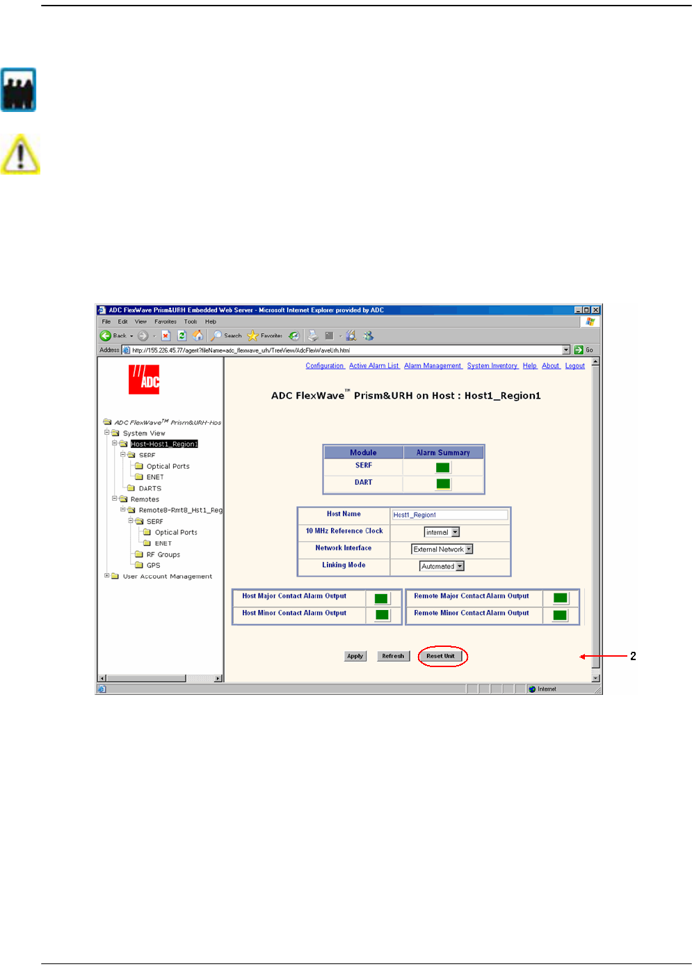
9.2 RESETTING THE HOST UNIT
11 In the Function Explorer Tree, select
System View
, and then click on the Host name
node to open the
Host Summary
view in the EMS View Frame.
22 Click
Reset Unit
.
Only a user logged in under the admin or a Network Manager account can change Prism
system settings through the EMS.
Resetting the Host Unit results in a Loss of Service condition for the Host and connected
Remotes until the Host comes back up. Depending on the system configuration, it can
take 5 to 20 minutes for management communication to be restored.
Managing Host Units
Page 216 FlexWave Prism Host, Remote and EMS 5.1 System Reference
© 2009 ADC Telecommunications, Inc ADCP-77-073 • Issue 2 • 11/2009
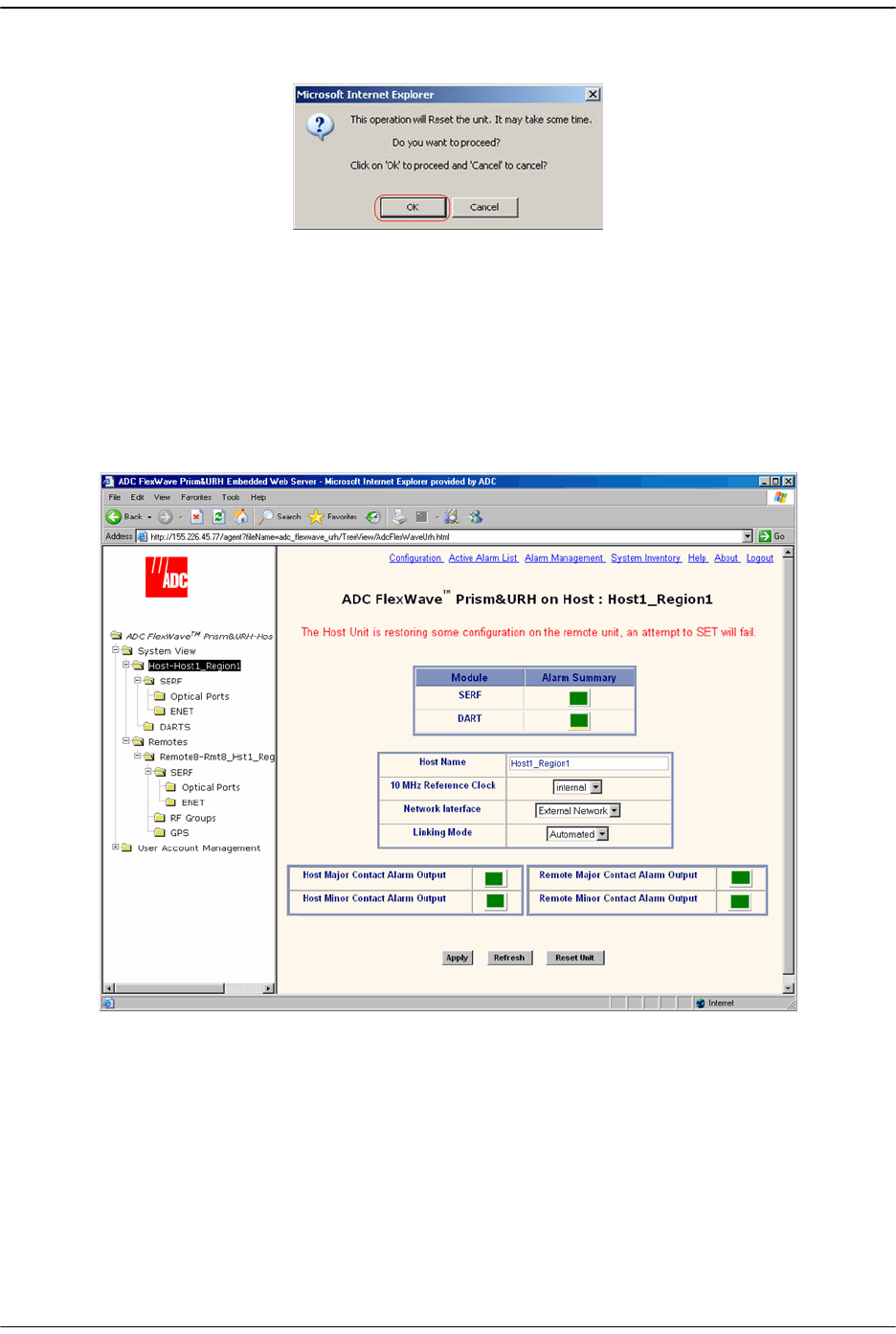
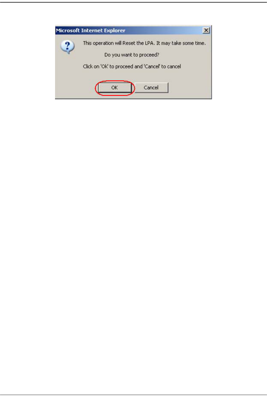
33 In the confirmation dialog, click
OK
.
Once you click OK, the confirmation dialog closes and the Host reboots. It will
take some time for the Host to retrieve data from connected Remotes and to
reconfigure data on the Remotes. During this time, an alert message displays in
the
Host Summary
view and on any other page where data can be set. Any attempt
to SET will fail. You cannot make configuration changes while this message is
displayed. Wait until the message clears before continuing with configuration
settings.
Viewing Host SeRF Ethernet Ports
FlexWave Prism Host, Remote and EMS 5.1 System Reference Page 217
ADCP-77-073 • Issue 2 • 11/2009 © 2009 ADC Telecommunications, Inc.
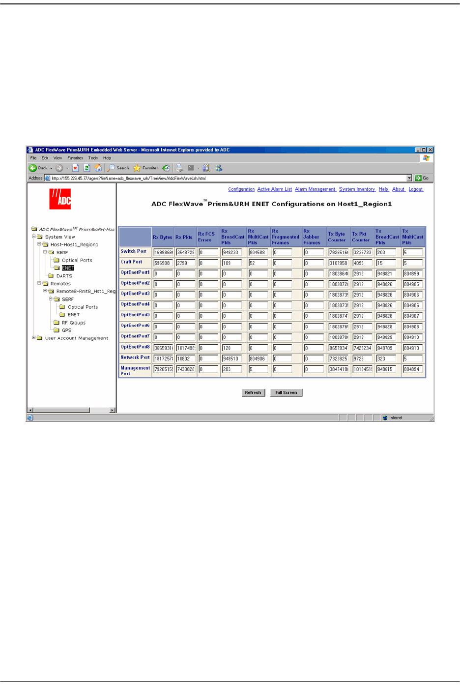
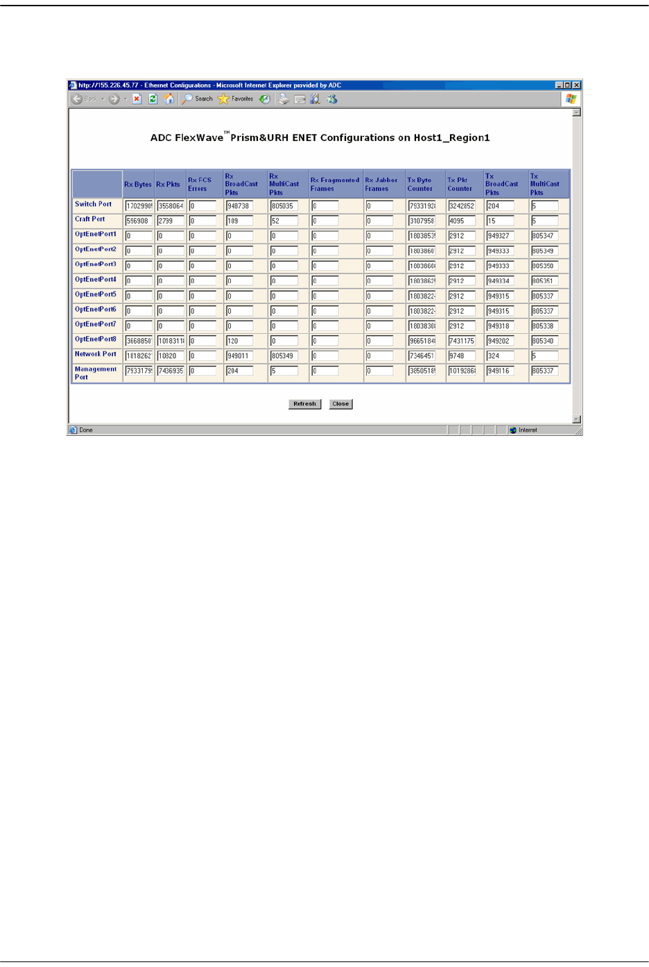
9.3 VIEWING HOST SERF ETHERNET PORTS
The Host
ENET Configurations
view is a summary of throughput and number of errors
on the twelve Ethernet (ENET) ports on the Host SeRF card. These ports consist of
eight ports used for connection to Remotes and four ports used for system
management and maintenance functions.
11 In the Function Explorer Tree, select
System View
,
Host-
x,
SERF
,
ENET
(where
-
x is the
Host name) to open the
ENET Configurations
view in the EMS View Frame.
Managing Host Units
Page 218 FlexWave Prism Host, Remote and EMS 5.1 System Reference
© 2009 ADC Telecommunications, Inc ADCP-77-073 • Issue 2 • 11/2009
22 (Optional) To enlarge the view, click Full Screen to open a separate window that
shows only the
ENET Configurations
table.
33 To update the counters, click
Refresh
.
The
ENET Configurations
view lists the Ethernet ports and their corresponding
status.
•• The row headers in the first column are as follows:
–
Switch Port
—on card processor's connection to the switch on the SeRF card
–
Craft Port
—on card processor's connection to the PHY port labeled Craft
–
OptEnetPort1-8
—Ethernet switch interface to SFP 1-8
–
Network Port
—Ethernet switch interface to on-card processor
–
Management Port
—switch interface to the PHY port labeled Network
•• The column headers, from left to right, are as follows:
–
Rx Bytes
—Receive byte counter. Increments by the byte count of frames
received, including those in bad packets, excluding preamble and SFD but
including FCS bytes
–
Rx Pkts
—Receive packet counter. Increments for each frame received
packet (including bad packets, all unicast, broadcast, and multicast
packets)
–
Rx FSC Errors
—Receive FCS error counter. Increments for each frame
received that has an integral 64 to 1518 length and contains a frame check
sequence error

Viewing Host SeRF Ethernet Ports
FlexWave Prism Host, Remote and EMS 5.1 System Reference Page 219
ADCP-77-073 • Issue 2 • 11/2009 © 2009 ADC Telecommunications, Inc.
–
Rx BroadCast Pkts
—Receive broadcast packet counter. Increments for each
broadcast good frame of lengths 64 to 1518 (non VLAN) or 1522 (VLAN),
excluding multicast frames. Does not include range/length errors
–
Rx MultiCast Pkts
—Receive multicast packet counter. Increments for each
multicast good frame of lengths 64 to 1518 (non VLAN) or 1522 (VLAN),
excluding broadcast frames. This count does not include range/length
errors
–
Rx Fragmented Frames
—Receive fragments counter. Increments for each
frame received that is less than 64 bytes and contains an invalid FCS. This
includes integral and non-integral lengths
–
Rx Jabber Frames
—Receive jabber counter. Increments for frames received
that exceed 1518 (non VLAN) or 1522 (VLAN) bytes and contain an invalid
FCS. This includes alignment errors
–
Tx Byte Counter
—Transmit byte counter. Increments by the number of bytes
that were put on the wire including fragments of frames that were involved
with collisions. This count does not include preamble/SFD or jam bytes.
This counter does not count if the frame is truncated
–
Tx Pkt Counter
—Transmit packet counter. Increments for each transmitted
packet (including bad packets, excessive deferred packets, excessive
collision packets, late collision packets, all unicast, broadcast, and
multicast packets)
–
Tx BroadCast Pkts.
—Transmit broadcast packet counter. Increments for
each broadcast frame transmitted (excluding multicast frames)
–
Tx MultiCast Pkts.
—Transmit multicast packet counter. Increments for each
multicast valid frame transmitted (excluding broadcast frames)
Managing Host Units
Page 220 FlexWave Prism Host, Remote and EMS 5.1 System Reference
© 2009 ADC Telecommunications, Inc ADCP-77-073 • Issue 2 • 11/2009
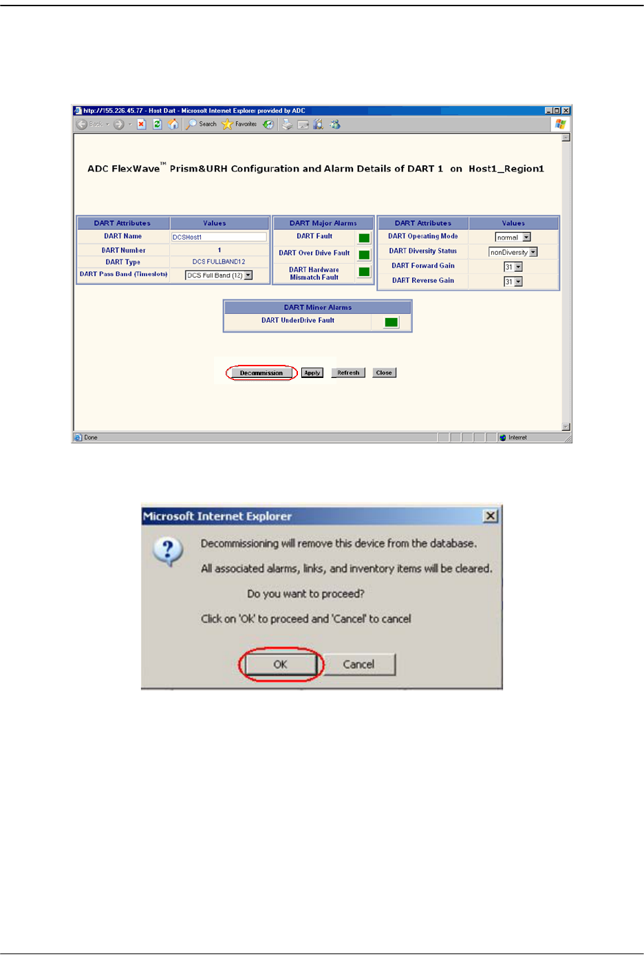
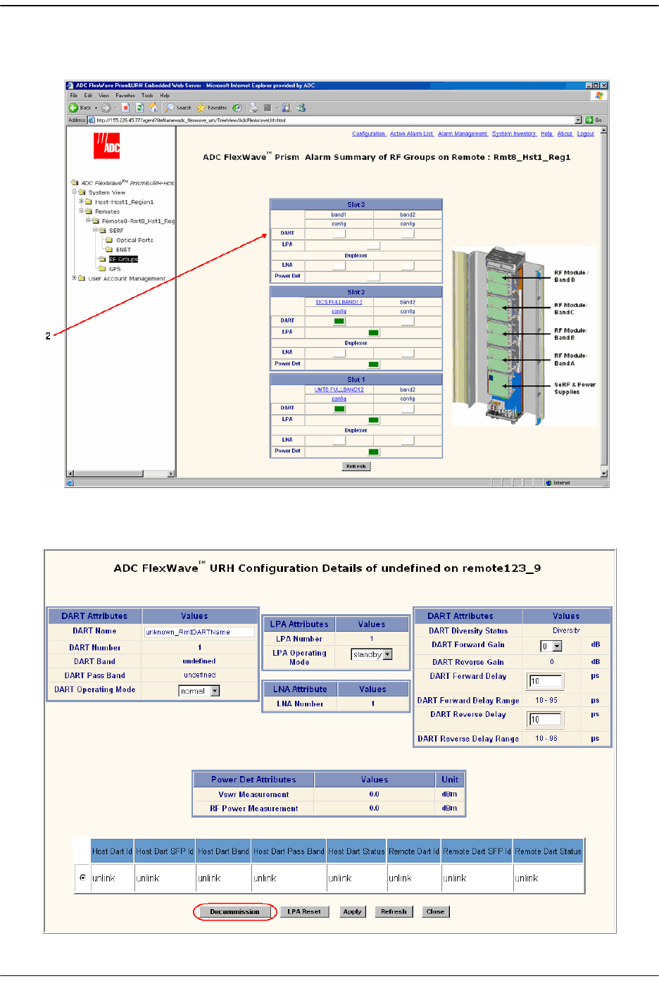
9.4 DECOMMISSIONING A DART IN A HOST
The
Decommission
button is available only when a DART has already been physically
removed. You use the
Decommission
button to remove DART configuration settings
and to delete DART alarms from EMS alarm summaries. Entries in the Alarm History
Log, however, are preserved.
11 In the Function Explorer Tree, select
System View
,
Host-
x,
SERF
,
DARTS
(where
-
x is
the Host name) to open the
DART’s Alarm Summary
view in the EMS View Frame.
Only a user logged in under the admin or a Network Manager account can change Prism
system settings through the EMS.
This procedure is for decommissioning a DART in a Host. For information on
decommissioning a DART in a Remote, see “Decommissioning an RF Module in a Remote”
on page 232.
Decommission a DART only if it has been permanently removed from the Remote and
will not be replaced with another DART. When a DART is taken out of service, this
procedure removes information about the DART (such as associated alarms, links, and
inventory) from the EMS database.
You must delete any RF links before you can decommission a Host DART. The FlexWave
system prevents a decommission if RF links are in place.
Decommissioning a DART in a Host
FlexWave Prism Host, Remote and EMS 5.1 System Reference Page 221
ADCP-77-073 • Issue 2 • 11/2009 © 2009 ADC Telecommunications, Inc.
22 In the
Information
column, click on the
Band-Config
link for the DART to be
decommissioned. The
Configuration and Alarm Details
window opens.
33 In the
Configuration and Alarm Details
window, click the
Decommission
button.
44 In the confirmation dialog, click
OK
.
Managing Host Units
Page 222 FlexWave Prism Host, Remote and EMS 5.1 System Reference
© 2009 ADC Telecommunications, Inc ADCP-77-073 • Issue 2 • 11/2009
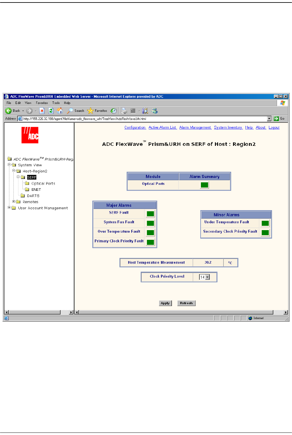
9.5 VIEWING THE HOST SERF SUMMARY
The
Host SERF
page provides a summary for the SeRF (Serial Radio Frequency) card
located in the Host. The Host SeRF card contains the processor chip where the EMS
software documented in this manual resides. The SeRF controls communication
between the Host and the Remotes, and maintains the system configuration settings.
In the Function Explorer Tree, select
System View
,
Host-
x,
SERF
(where
-
x is the Host
name) to open the
Prism on SERF of Host
-n view in the EMS View Frame.
The
Prism on SERF of Host
-n view has the following elements:
•
Optical Ports
—alarm status indicator for Host optical ports. Red indicates that an
alarm exists for at least one of the eight optical ports on the SeRF card. Yellow
indicates a minor alarm.
•
SERF Fault
—state of the SeRF. Red indicates that either the SeRF clock source is
unacceptable or the SeRF card FPGA is not programmed.
•
System Fan Fault
—state of the Host chassis fan. Red indicates that the Host chassis
fan is spinning too slowly.

Viewing the Host SeRF Summary
FlexWave Prism Host, Remote and EMS 5.1 System Reference Page 223
ADCP-77-073 • Issue 2 • 11/2009 © 2009 ADC Telecommunications, Inc.
•
Over Temperature Fault
—Red indicates that the current chassis-internal
temperature of the Host is above its operating limits. Fault threshold is
90° C
.
•
Primary Clock Priority Fault
—Indicates that there is another Host in a Multi-Host
system that has the same Clock Priority Level (CPL) as this Host. All Hosts that are
in conflict generate this alarm. When all Hosts with this alarm are provisioned
with unique CPLs, the alarm clears. Service is disrupted on all systems when this
alarm is present. The
Primary Clock Priority Fault
is a Major alarm.
•
Under Temperature Fault
—Yellow indicates that the current chassis-internal
temperature of the Host is below its operating limits. Fault threshold is
-40° C
.
•
Secondary Clock Priority Fault
—In a three-Host system, indicates that the Clock
Priority Level for the Host managing the Remote has been changed. All Hosts in
the system generate this alarm. When all Hosts with this alarm are provisioned
with unique CPLs, the alarm clears. Service is not disrupted, but could become
disrupted if the host providing the clock becomes unavailable. The
Secondary Clock
Priority Fault
is a Minor alarm.
•
Host Temperature Measurement
—Gives the current chassis-internal temperature in
degrees Centigrade detected by the Host.
For corrective actions for alarm states, refer to “Troubleshooting Alarms” on
page 264. For information on setting the Clock Priority Level, see “Set the Clock
Priority Level” on page 150.
Managing Host Units
Page 224 FlexWave Prism Host, Remote and EMS 5.1 System Reference
© 2009 ADC Telecommunications, Inc ADCP-77-073 • Issue 2 • 11/2009
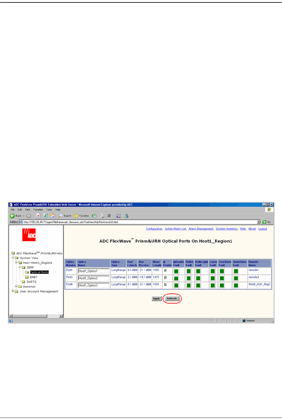
9.6 VIEWING HOST SERF OPTICAL PORTS
The
Host Optical Ports
view shows the current usage and alarm status of the optical
ports on the Host plus the current values of some key operating parameters. The Host
has eight optical ports, but the
Host Optical Ports
view only shows active ports
(physically connected to a Remote). Each port in the page represents one set of
forward and reverse paths between a Host and Remote. Physically, this may have
been accomplished with two fibers through that port or with a single fiber (if WDM is
used). Each physical port contains an SFP transceiver with two connectors.
The
Host Optical Ports
view provides a link that can be used to enter or edit the name
for a Host optical port (see “Enter a Host Name, Clock Source, and Linking Mode” on
page 147).
For corrective actions for alarm states, refer to “Troubleshooting Alarms” on
page 264.
To access the
Host Optical Ports
view, in the Function Explorer Tree, select
System View
,
Host-
x,
SERF
,
Optical Ports
(where
-
x is the Host name).
The
Optical Ports
view for
Host
-n opens in the EMS View Frame, which only shows the
Receive power level from the Remote unit (REV path). To see the Receive power level
in the FWD path (from the Host to the Remote), you must open the
Optical Ports
view
for the desired Remote as described in “Viewing Remote SeRF Optical Ports” on
page 248.

Viewing Host SeRF Optical Ports
FlexWave Prism Host, Remote and EMS 5.1 System Reference Page 225
ADCP-77-073 • Issue 2 • 11/2009 © 2009 ADC Telecommunications, Inc.
The following informational columns are provided in the
Optical Ports
table.
•
Optics Number
—System assigned port number. This is a link to the
Port
Configuration Page
for this particular port.
•
Optics Name
—user entered port name or
UNKNOWN_SFPName
, which indicates that
no name has been entered.
•
Optics Type
—indicates that the laser range, which is
LongRange
to meet 3Gbps
optical transmission requirements.
•
Fwd Launch
—Launch power level in dBm of forward path signal. The minimum
FWD launch power is -2 dBm, and the maximum is 3 dBm.
•
Rev Receive
—Receive power level in dBm of reverse path signal, which incorporates
the launch power of the Remote Unit SFP plus all optical losses (insertion losses,
fiber cable loss, and so forth). The minimum REV launch power is -27 dBm, and
the maximum is -9 dBm.
•
Wave Length
—Number displayed is wave length transmitted through this port:
– Non-duplex and WDM configurations: 1550 nm fwd, 1310 rev
– CWDM configurations can be one of eight wavelengths: 1470, 1490, 1510,
1530, 1550, 1570, 1590, 1610.
•
IpEnable Fault
—An attempt to enable IP on a fiber (Host) to a Remote that already
has IP enabled on another fiber (Host) has been made. The alarm is cleared if IP is
disabled on the fiber. It is also cleared if IP becomes enabled. This latter condition
can occur if the fiber that was already carrying IP later has IP disabled, or if the
fiber otherwise becomes disabled. For information on setting Ip Enable, see
“Configure the Remote SeRF Optical Ports” on page 158.
•
RxBer Fault
—Yellow indicates that too many errors have been received on the
receiving fiber. Fault threshold is
0.00001
. Threshold cannot be changed.
•
RxNoLight Fault
—Red indicates that no light is detected on the receiving fiber. Fault
threshold is below
-34dBm
.
•
Laser Fault
—Red indicates that the forward path laser is faulty.
•
OverDrive Fault
—Red indicates power of signal received on the fiber is too strong.
Fault threshold is
-9dBm
. Threshold cannot be changed.
•
UnderDrive Fault
—Yellow indicates power of signal received on fiber is too weak.
Fault threshold is
-27dBm
. Threshold cannot be changed.
•
Remote Name
—name of the Remote connected to this Optics port.
Managing Host Units
Page 226 FlexWave Prism Host, Remote and EMS 5.1 System Reference
© 2009 ADC Telecommunications, Inc ADCP-77-073 • Issue 2 • 11/2009
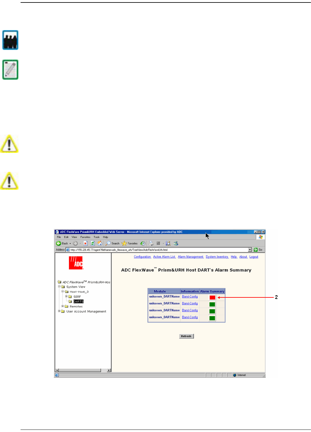
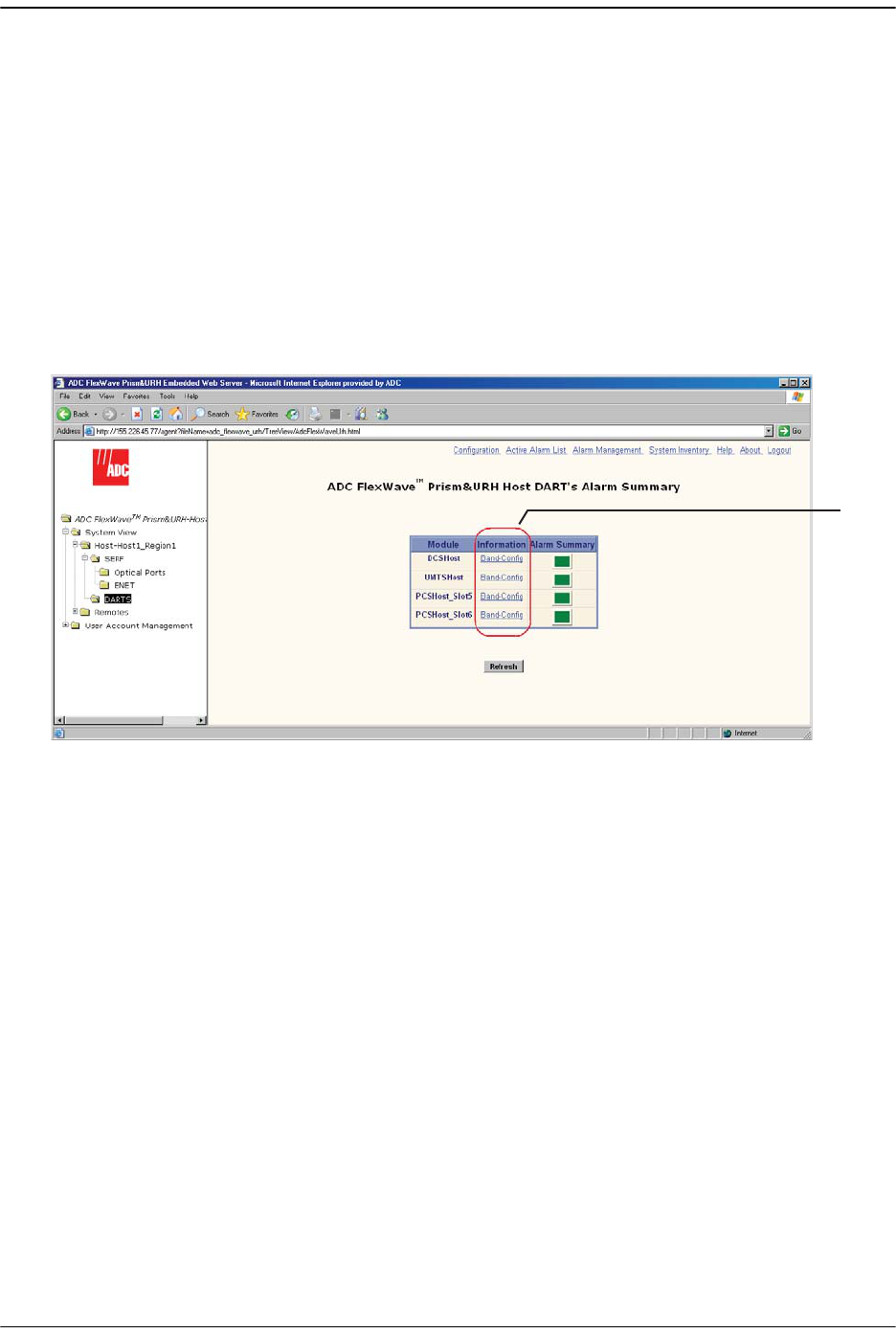
9.7 VIEWING HOST DART ALARMS
A Host may support up to eight DART cards. Each DART card provides one RF band
for up to eight Remotes. The DART card converts between serial (optical) and RF data
in both forward and reverse directions. The
Prism Host DART’s Alarm Summary
view lists
all DART cards currently installed in the Host and provides an alarm summary status
indicator for each card. This page also provides a link, for each DART card, to a more
detailed page that can be used to configure the DART card and obtain alarm details
(for more information, see “Configure the Host DARTs” on page 152).
11 In the Function Explorer Tree, select
System View
,
Host-
x,
SERF
,
DARTS
(where
-
x is
the Host name) to open the
Host DART’s Alarm Summary
view in the EMS View
Frame.
22 In the
Information
column, click on the
Band-Config
link for the DART that you want
to monitor. The
Configuration and Alarm Details of DART
n
on Host-
x window opens
(where
DART
n corresponds to the DART whose
Band-Config
link you selected).
2
Viewing Host DART Alarms
FlexWave Prism Host, Remote and EMS 5.1 System Reference Page 227
ADCP-77-073 • Issue 2 • 11/2009 © 2009 ADC Telecommunications, Inc.
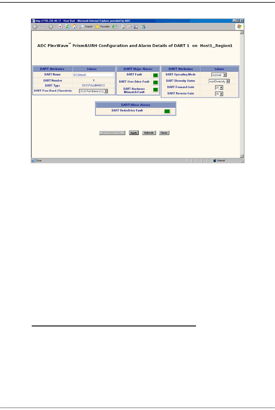
The
Configuration and Alarm Details of DART
n
on Host-
x window shows the following
Host DART alarms:
•
DART Fault
—Summary alarm state of the DART card. Red indicates a problem
with passing RF.
•
DART Over Drive Fault
—Red indicates that the RF signal received from the BTS
is too strong. Fault threshold is
+20dBm
.
•
DART Hardware Mismatch Fault
—Red indicates that the DART type doesn't match
the assigned Pass Band. Examples: After assigning the Pass Band, if the DART
is changed with another DART type, then the
DART Hardware Mismatch Fault
occurs. Or, if you swap DART types (such as, from GSM1800 to UMTS), the
DART Hardware Mismatch Fault
is raised as the stored database has one DART
type configured, and the new hardware doesn't match it.
•
DART UnderDrive Fault
—Yellow indicates that the power of the signal received
on the RF input to the DART is 20 dB below the optimal input level. For
example:
33 Click
Refresh
to update the alarm summary. For corrective actions for alarm states,
refer to “Troubleshooting Alarms” on page 264.
Host Forward
DART Gain
Maximum RMS
Input Power
UnderDrive
Threshold
30 dB -25 dBm -45 dBm
20 dB -15 dBm -35 dBm
10 dB -5 dBm -25 dBm
0 dB +5 dBm -15 dBm

Managing Host Units
Page 228 FlexWave Prism Host, Remote and EMS 5.1 System Reference
© 2009 ADC Telecommunications, Inc ADCP-77-073 • Issue 2 • 11/2009
Intentionally Blank Page

FlexWave Prism Host, Remote and EMS 5.1 System Reference Page 229
ADCP-77-073 • Issue 2 • 11/2009 ©2009 ADC Telecommunications, Inc.
10 MANAGING REMOTE UNITS
10.1 Viewing Remote SeRF Ethernet Ports.................................................................230
10.2 Decommissioning an RF Module in a Remote ......................................................232
10.3 Configuring Dual-Slot LPAs ..............................................................................235
10.4 Restarting an LPA ...........................................................................................236
10.4.1 Identify the LPA Fault ..............................................................................236
10.4.2 Reset the LPA.........................................................................................238
10.5 Monitoring a Remote Unit ................................................................................240
10.6 Decommissioning a Remote Unit.......................................................................244
10.7 Resetting a Remote Unit..................................................................................246
10.8 Viewing Remote SeRF Alarms...........................................................................248
10.9 Viewing Remote SeRF Optical Ports...................................................................248
10.10 Viewing an Alarm Summary of the Remote RF Groups .......................................250
10.11 Viewing RF Band Alarm Details .......................................................................252
10.12 Viewing Remote GPS Alarms and Location Parameters .......................................255
Content Page
Managing Remote Units
Page 230 FlexWave Prism Host, Remote and EMS 5.1 System Reference
© 2009 ADC Telecommunications, Inc ADCP-77-073 • Issue 2 • 11/2009
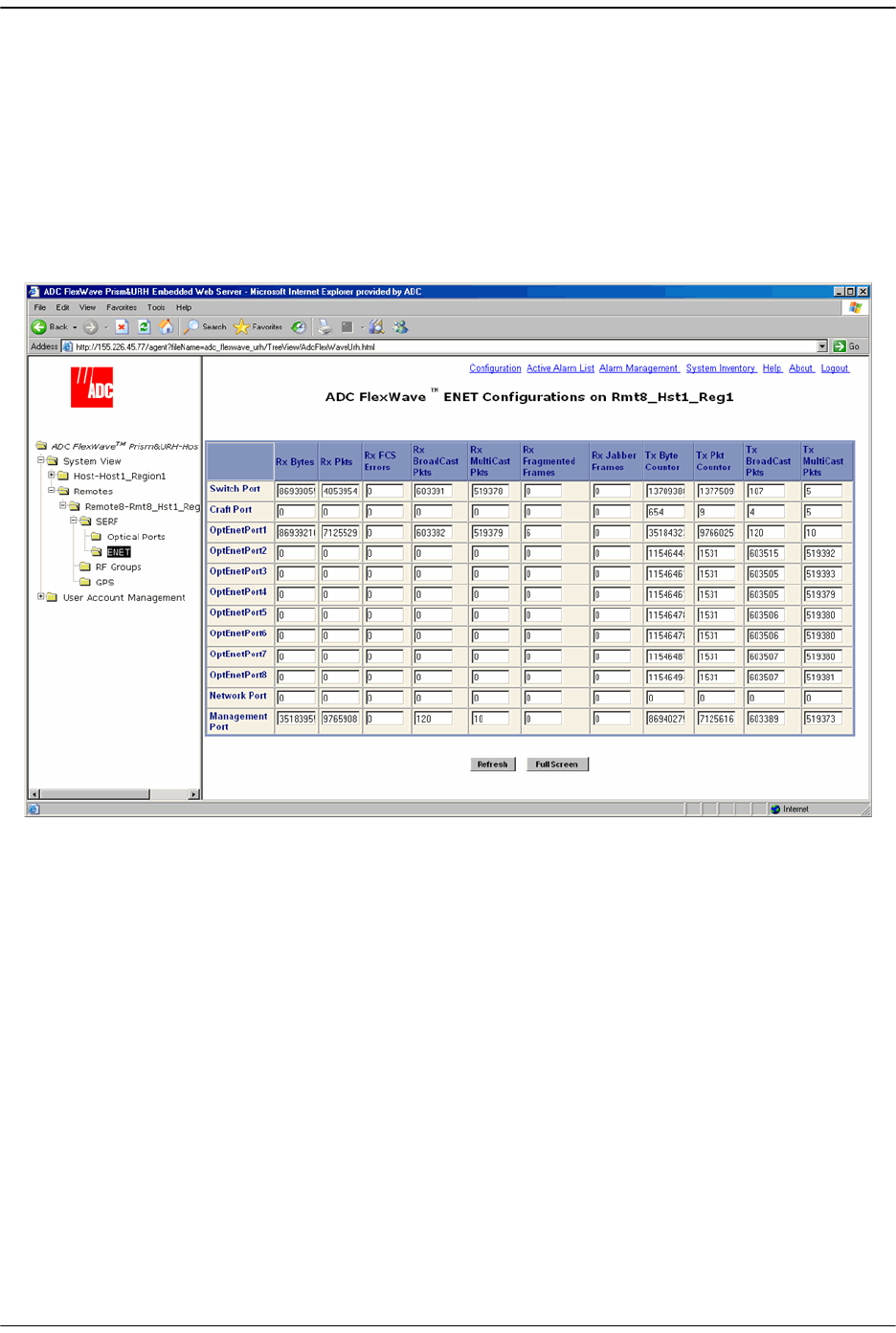
10.1 VIEWING REMOTE SERF ETHERNET PORTS
The Remote SERF ENET page is a summary of throughput and number of errors on
the twelve Ethernet (ENET) ports on the Remote SeRF card. These ports, located on
the front side of the SeRF card, consist of eight ports used for connection to Remotes
and four ports used for system management and maintenance functions.
To open the
ENET Configurations
view in the EMS View Frame, in the Function Explorer
Tree select
System View
,
Remotes
,
SERF
,
ENET
.
The
ENET Configurations
view lists the Ethernet ports and their corresponding status.
•
Switch Port
—on card processor's connection to the switch on the SeRF card
•
Craft Port
—on card processor's connection to the PHY port labeled Craft
•
OptEnetPort1-8
—Ethernet switch interface to SFP 1-8
•
Network Port
—Ethernet switch interface to on-card processor
•
Management Port
—switch interface to the PHY port labeled Network
•
Rx Bytes
—Receive byte counter. Increments by the byte count of frames received,
including those in bad packets, excluding preamble and SFD but including FCS
bytes
•
Rx Pkts
—Receive packet counter. Increments for each frame received packet
(including bad packets, all unicast, broadcast, and multicast packets)
•
Rx FSC Errors
—Receive FCS error counter. Increments for each frame received that
has an integral 64 to 1518 length and contains a frame check sequence error

Viewing Remote SeRF Ethernet Ports
FlexWave Prism Host, Remote and EMS 5.1 System Reference Page 231
ADCP-77-073 • Issue 2 • 11/2009 © 2009 ADC Telecommunications, Inc.
•
Rx BroadCast Pkts
—Receive broadcast packet counter. Increments for each
broadcast good frame of lengths 64 to 1518 (non VLAN) or 1522 (VLAN),
excluding multicast frames. Does not include range/length errors
•
Rx MultiCast Pkts
—Receive multicast packet counter. Increments for each multicast
good frame of lengths 64 to 1518 (non VLAN) or 1522 (VLAN), excluding
broadcast frames. This count does not include range/length errors
•
Rx Fragmented Frames
—Receive fragments counter. Increments for each frame
received that is less than 64 bytes and contains an invalid FCS. This includes
integral and non-integral lengths
•
Rx Jabber Frames
—Receive jabber counter. Increments for frames received that
exceed 1518 (non VLAN) or 1522 (VLAN) bytes and contain an invalid FCS. This
includes alignment errors
•
Tx Byte Counter
—Transmit byte counter. Increments by the number of bytes that
were put on the wire including fragments of frames that were involved with
collisions. This count does not include preamble/SFD or jam bytes. This counter
does not count if the frame is truncated
•
Tx Pkt Counter
—Transmit packet counter. Increments for each transmitted packet
(including bad packets, excessive deferred packets, excessive collision packets,
late collision packets, all unicast, broadcast, and multicast packets)
•
Tx BroadCast Pkts.
—Transmit broadcast packet counter. Increments for each
broadcast frame transmitted (excluding multicast frames)
•
Tx MultiCast Pkts.
—Transmit multicast packet counter. Increments for each
multicast valid frame transmitted (excluding broadcast frames)

Managing Remote Units
Page 232 FlexWave Prism Host, Remote and EMS 5.1 System Reference
© 2009 ADC Telecommunications, Inc ADCP-77-073 • Issue 2 • 11/2009
10.2 DECOMMISSIONING AN RF MODULE IN A REMOTE
The
Decommission
button is available only when a RF Module and hence the DART(s)
have already been physically removed. You use the
Decommission
button when an RF
Module and its DART(s) have taken out of service. This procedure removes all
information about this RF Module (such as associated alarms, links, and inventory)
from the EMS database. Entries in the Alarm History Log, however, are preserved.
11 In the Function Explorer Tree, select
System View
,
Remotes
,
Remote#-
x,
SERF
,
Optical
Ports
(where
Remote#
indicates the Remote number that corresponds to a Host SFP
port number and n is the Remote name).
The
Alarm Summary of RF Groups
view opens in the EMS View Frame. For a
description of the RF Groups, see “RF Groups in the Remote and the EMS GUI” on
page 160.
Only a user logged in under the admin or a Network Manager account can change Prism
system settings through the EMS.
Decommission a RF Module only if it has been permanently removed from the Remote
and will not be replaced with another DART.
This procedure is for decommissioning a Remote’s RF Modules, which contain the
Remote DARTS. For information on decommissioning a DART in a Host, see
“Decommissioning a DART in a Host” on page 220.
Decommissioning an RF Module in a Remote
FlexWave Prism Host, Remote and EMS 5.1 System Reference Page 233
ADCP-77-073 • Issue 2 • 11/2009 © 2009 ADC Telecommunications, Inc.
22 In the rectangle for the RF group selected, click on the
config
link for the band
whose DART needs to be decommissioned.
33 In the
Configuration Details
window, click the
Decommission
button.

Managing Remote Units
Page 234 FlexWave Prism Host, Remote and EMS 5.1 System Reference
© 2009 ADC Telecommunications, Inc ADCP-77-073 • Issue 2 • 11/2009
44 In the confirmation dialog, click
OK
.
Configuring Dual-Slot LPAs
FlexWave Prism Host, Remote and EMS 5.1 System Reference Page 235
ADCP-77-073 • Issue 2 • 11/2009 © 2009 ADC Telecommunications, Inc.
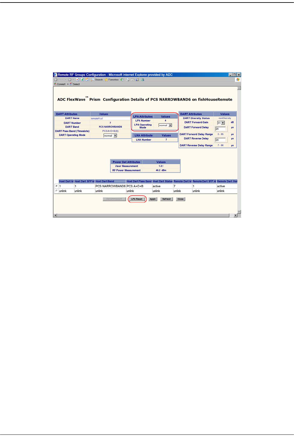
10.3 CONFIGURING DUAL-SLOT LPAS
Both LPAs in a dual-slot 40W module can be controlled from the
Configuration Details
window, which allows you to set the
LPA Operating Mode
, enable/disable a LPA, or
reset a LPA, as shown below:
The following rules apply to the dual-slot LPA installation:
•• For the second LPA, the GUI displays it in an RF group by itself. There will be no
DART in the RF group. However, you will be able to view alarms and configuration
for the RF group in case of dual LPA setup. For the “missing” DART, default values
will display. You cannot configure the missing DARTs, but can set the LPA mode
and reset the LPA.
•• User-initiated configuration of dual LPAs is simulataneous for both the LPAs. If
one of the LPAs is placed into
standby
, both go into standby. If one is placed into
normal
mode, both go into
normal
mode.
•• User initiated LPA resets are simulataneous. If one LPA is reset, so is the other.
•• Alarm handling for the two LPAs occurs independently. If one alarms and goes
into
standby
, the second LPA continues in its current state. Automatic alarm
recovery is also handled independently.
Managing Remote Units
Page 236 FlexWave Prism Host, Remote and EMS 5.1 System Reference
© 2009 ADC Telecommunications, Inc ADCP-77-073 • Issue 2 • 11/2009
10.4 RESTARTING AN LPA
You use the
LPA Reset
button to bring an LPA back into service (restart) that stopped
because of an LPA alarm.
This section comprises a 6-step process that is broken into 2 sections that first
identifies the fault and then resets the LPA.
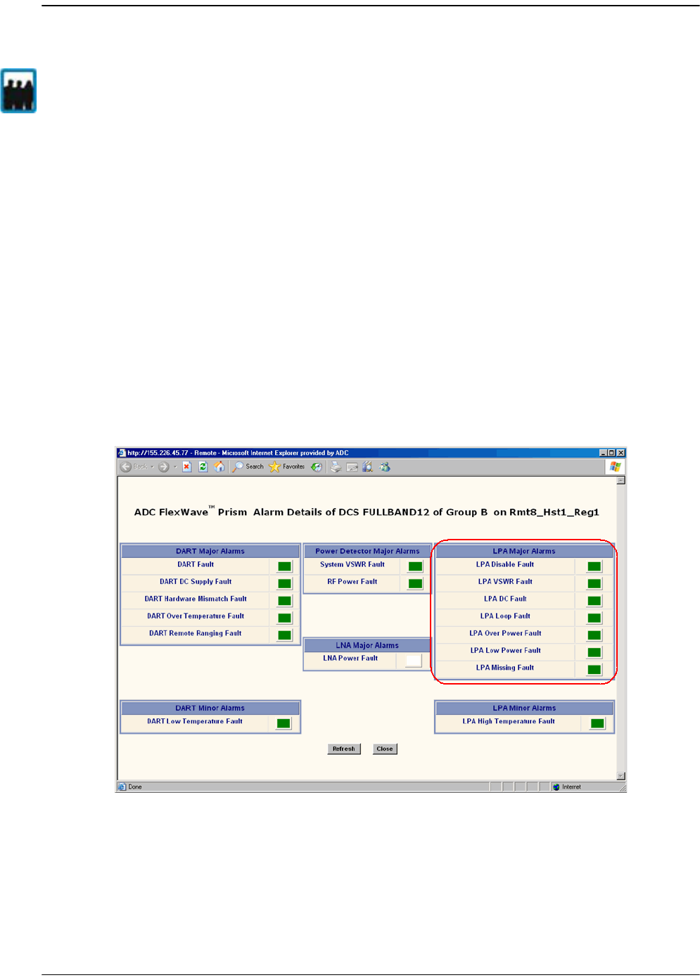
10.4.1 Identify the LPA Fault
11 In the Function Explorer Tree, select
System View
,
Remotes
,
Remote#-
x,
RF Groups
(where
Remote#
indicates the Remote number that corresponds to a Host SFP port
number and n is the Remote name).
22 In the rectangle for the RF group selected, click on the
band
link for the band
whose LPA needs to be reset. The
Alarm Details of DART-
x
of Group
x
on Remote#-
x
window opens (where x is the DART, Group or Remote name).
An LPA Reset is necessary when any of the alarms listed below have occurred.
•
LPA Disable Fault
—Red indicates that the Linear Power Amplifier is disabled
because it encountered a problem. Check for a corresponding LPA fault listed in
this section (such as
LPA Loop Fault
,
LPA Over Power Fault
, and so forth), then correct
the LPA fault. If LPA Reset does not clear this alarm, the corresponding RF Module
Only a user logged in under the admin or a Network Manager account can change Prism
system settings through the EMS.

Restarting an LPA
FlexWave Prism Host, Remote and EMS 5.1 System Reference Page 237
ADCP-77-073 • Issue 2 • 11/2009 © 2009 ADC Telecommunications, Inc.
may need to be replaced. Contact ADC Technical Assistance for further help (see
“Contacting ADC” on page 335).
•
LPA VSWR Fault
—Red indicates an internal VSWR fault state of the LPA. Check the
Remote’s antenna connection. If the connection is good and a subsequent LPA
reset does not clear the alarm, inspect the blue cable going from the
corresponding Remote Antenna port to the Duplexer—verify that the connection
is tight. If this doesn't clear the fault, the Duplexer may need to be replaced. Notify
ADC Technical Support (see “Contacting ADC” on page 335).
•
LPA DC Fault
—Red indicates that the voltage level inside the LPA is outside its
acceptable range. If the LPA Reset does not clear this alarm, contact ADC
Technical Assistance for further help as the RF Module that contains the LPA or
the Power supply within the SeRF Module may need to be replaced (see
“Contacting ADC” on page 335).
•
LPA Loop Fault
—Red indicates that the LPA is not sure of the feedback loop, so it
has placed itself into a safe state. You can attempt to recover the LPA by reducing
forward gain by 10dB on both DART cards, resetting the LPA, then restoring GAIN.
If the reset does not work, contact ADC Technical Support (see “Contacting ADC”
on page 335).
•
LPA Over Power Fault
—Red indicates that the power level inside the LPA is high
enough to damage the LPA. Reduce the Remote Forward Gain (see “Link the Host
and Remote DARTs.” on page 159), then reset the LPA.
•
LPA Low Power Fault
—Red indicates that the internal gain of the LPA does not meet
specifications. In addition to an LPA Reset, try putting the LPA into standby and
then back to enable to see if this clears this fault. If neither troubleshooting step
clears this alarm, the corresponding RF Module may need to be replaced. contact
ADC Technical Assistance for further help (see “Contacting ADC” on page 335).
•LPA Missing Fault—Red indicates that the LPA is missing. This fault cannot be cleared
with an LPA Reset.
Managing Remote Units
Page 238 FlexWave Prism Host, Remote and EMS 5.1 System Reference
© 2009 ADC Telecommunications, Inc ADCP-77-073 • Issue 2 • 11/2009
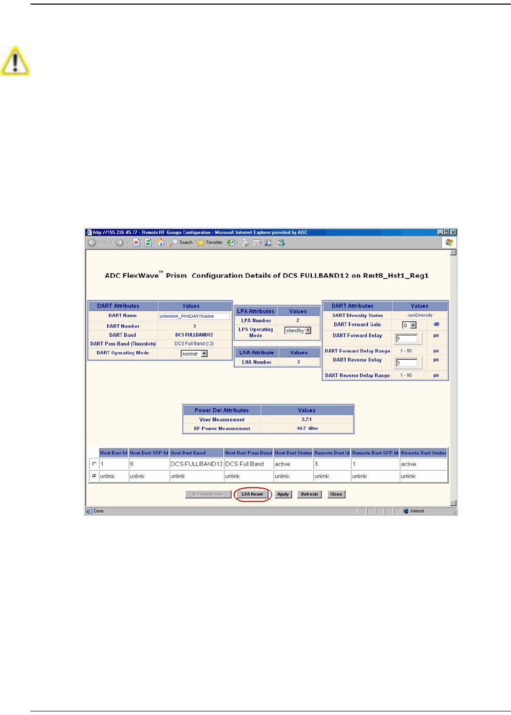
10.4.2 Reset the LPA
33 In the Function Explorer Tree, select
System View
,
Remotes
,
Remote#-
x,
SERF
,
RF
Groups
(where
Remote#
indicates the Remote number that corresponds to a Host
SFP port number and n is the Remote name).
44 In the rectangle for the RF group selected, click on the
config
link for the band
whose LPA needs to be reset.
55 In the
Configuration Details
window, click the
LPA Reset
button.
Once an LPA Reset is started, Loss of Service occurs. It take approximately 10 to 20
seconds before the LPA signal recovers. The GUI RF power reading will take longer
depending on the number of Remotes equipped—for a fully loaded Prism system with 8
Remotes the power reading could take several minutes to update.
Restarting an LPA
FlexWave Prism Host, Remote and EMS 5.1 System Reference Page 239
ADCP-77-073 • Issue 2 • 11/2009 © 2009 ADC Telecommunications, Inc.
66 In the LPA Reset caution dialog, click OK.
Managing Remote Units
Page 240 FlexWave Prism Host, Remote and EMS 5.1 System Reference
© 2009 ADC Telecommunications, Inc ADCP-77-073 • Issue 2 • 11/2009
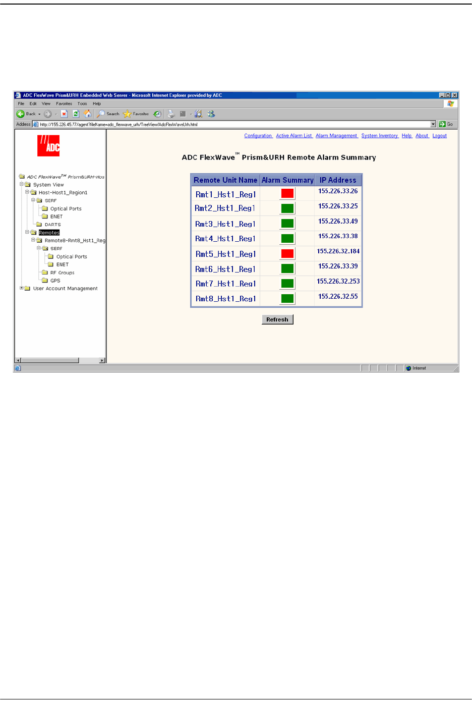
10.5 MONITORING A REMOTE UNIT
11 In the Function Explorer Tree, select
System View
,
Remotes
to open the top level
Remote Alarm Summary
view in the EMS View Frame.
22 If the Alarm Summary status indicator for any Remote is red or yellow, indicating
that an alarm exists for that Remote, in the Function Explorer Tree, select the node
that corresponds to that Remote. In the preceding example, you would click on
the remote node labeled
Rmt1_Hst1_Reg1
.
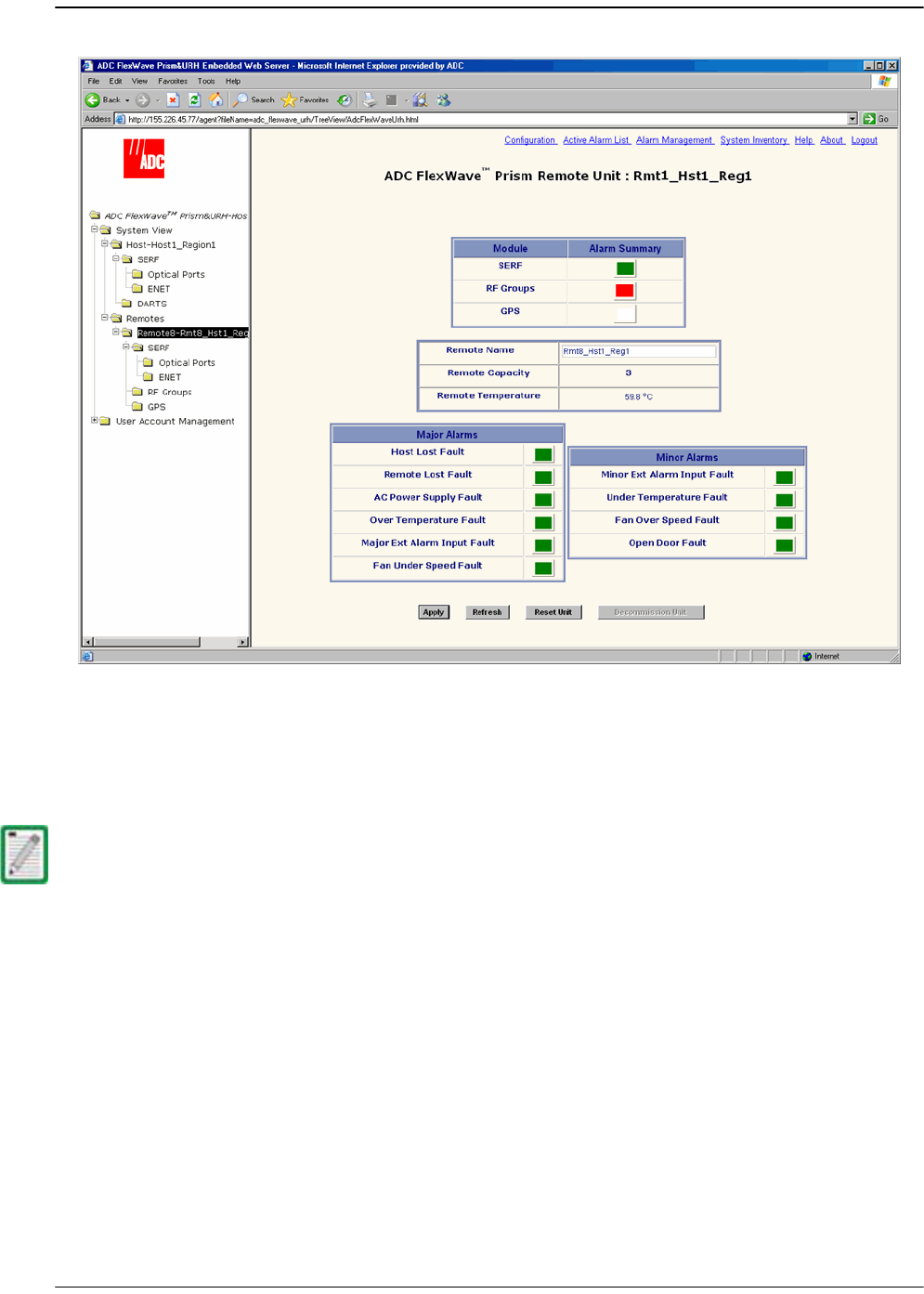
This opens the
Prism Remote Unit Remote
-n summary that corresponds to the
selected Remote (
Remote
-n).
Monitoring a Remote Unit
FlexWave Prism Host, Remote and EMS 5.1 System Reference Page 241
ADCP-77-073 • Issue 2 • 11/2009 © 2009 ADC Telecommunications, Inc.
33 If the
SERF
or
RF Groups Alarm Summary
status indicator is red or yellow, you must
go another level lower in the Function Explorer Tree for this same Remote to select
the page for the SeRF or RF Groups. For more information on these displays, see
“Viewing Remote SeRF Alarms” on page 248 or “Viewing Remote SeRF Optical
Ports” on page 248.
The GPS alarm is not supported at present; this status indicator will be white.

Managing Remote Units
Page 242 FlexWave Prism Host, Remote and EMS 5.1 System Reference
© 2009 ADC Telecommunications, Inc ADCP-77-073 • Issue 2 • 11/2009
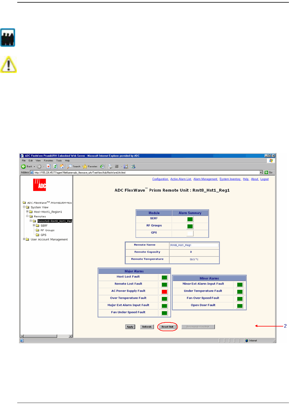
44 If any status indicator in the
Major Alarms
or
Minor Alarms
table is red or yellow,
refer to the following list:
•
Remote Capacity
—Number of slots for RF Modules in the remote. Each RF
Module comprises up to two Classic DARTS or Single SuperDARTs or one Dual
SuperDART.
•
Remote Temperature
field—Currently detected internal temperature of the
Remote (measured near the SeRF board).
•
Host Lost Fault
status indicator—Red indicates Remote has lost contact with
Host.
•
Remote Lost Fault
status indicator—Red indicates that the Host is unable to
communicate with the Remote.
•
AC Power Supply Fault
status indicator—Red indicates Remote power supply has
failed.
•
Over Temperature Fault
status indicator—Red indicates internal temperature in
Remote is over its functional operating limit. Fault threshold is
84°C
.
•
Fan Under Speed Fault
—Red indicates that the speed of the Remote fan is not
high enough for the internal functional temperature of the Remote.
•
Under Temperature Fault
status indicator—Yellow indicates that the internal
temperature within the Remote is under the operating limit. Fault threshold is
-40°C
.
•
Fan Over Speed Fault
—Yellow indicates that the Remote fan is not necessary for
the current internal temperature of the Remote, but the fan is spinning (Minor
alarm).
•
Open Door Fault
—Yellow status indicator for this Minor alarm, which indicates
that the door to the Remote is open.
•
Apply
button—When clicked, causes Remote Name entry to be applied
•
Refresh
button—When clicked, causes page to be reloaded from Host
DART ID 8
RF Slot 4
DART ID 7
DART ID 6
RF Slot 3
DART ID 5
DART ID 4
RF Slot 2
DART ID 3
DART ID 2
RF Slot 1
DART ID 1
SERF Board

Monitoring a Remote Unit
FlexWave Prism Host, Remote and EMS 5.1 System Reference Page 243
ADCP-77-073 • Issue 2 • 11/2009 © 2009 ADC Telecommunications, Inc.
•
Reset Unit
button—When clicked, causes the Remote to reboot. This causes a
Loss of Service until Remote has returned to normal operation. Typical down
time is two to four minutes. See “Resetting a Remote Unit” on page 246.
•
Decommission Unit
button—When clicked, deletes any configuration settings
for that Remote and removes all corresponding alarms from the EMS alarm
summaries (see “Decommissioning a Remote Unit” on page 244).
The use of the Reset Unit button causes Loss of Service and should not be used unless
other troubleshooting processes have been followed and did not fix the issue being
experienced at the Remote.
Managing Remote Units
Page 244 FlexWave Prism Host, Remote and EMS 5.1 System Reference
© 2009 ADC Telecommunications, Inc ADCP-77-073 • Issue 2 • 11/2009
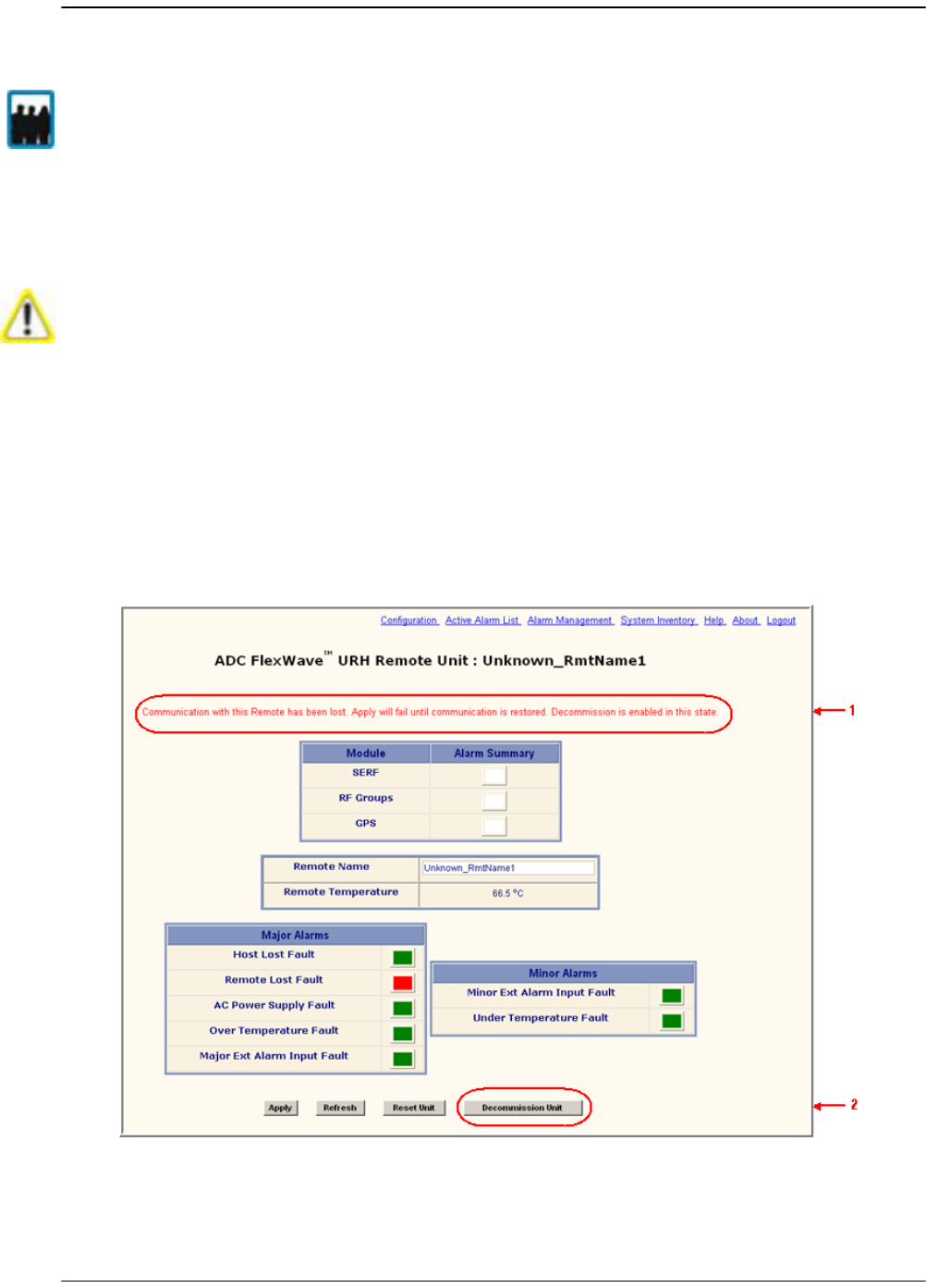
10.6 DECOMMISSIONING A REMOTE UNIT
The
Decommission
button is available only when a Remote has already been physically
removed from the system. You use the
Decommission
button to delete alarms related
to the removed Remote from the EMS alarm summaries.
11 If the system is configured for manual linking mode, remove any RF links to the
DART.
22 In the Function Explorer Tree, select the node that corresponds to the Remote that
has been physically removed from the Prism system.
This opens the
Prism Remote Unit Remote
-n summary that corresponds to the
selected Remote (
Remote
-n). There should be a statement that communication
with the Remote has been lost.
Only a user logged in under the admin or a Network Manager account can change Prism
system settings through the EMS.
Decommission a Remote only if it has been permanently removed from the Remote and
will not be replaced with another Remote. This procedure removes all information about
this Remote (such as associated alarms, links, and inventory) from the EMS database.
Decommissioning a Remote Unit
FlexWave Prism Host, Remote and EMS 5.1 System Reference Page 245
ADCP-77-073 • Issue 2 • 11/2009 © 2009 ADC Telecommunications, Inc.
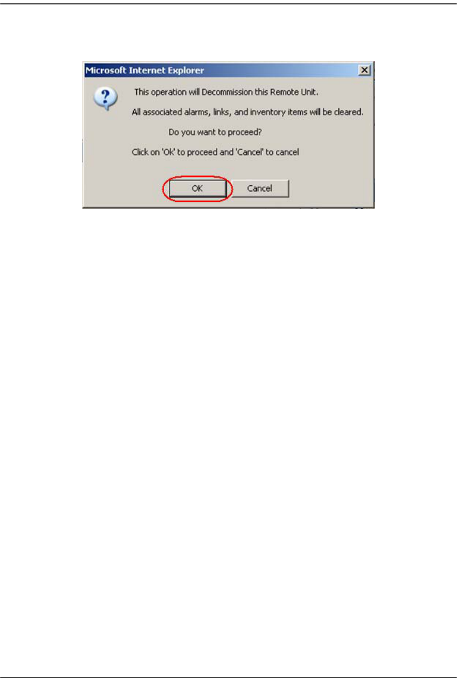
33 Click
Decommission Unit
.
44 In the confirmation dialog, click
OK
.
Managing Remote Units
Page 246 FlexWave Prism Host, Remote and EMS 5.1 System Reference
© 2009 ADC Telecommunications, Inc ADCP-77-073 • Issue 2 • 11/2009
10.7 RESETTING A REMOTE UNIT
If communication and/or reverse-path fiber is lost to the Remote, a Remote Reset can
be attempted.
11 In the Function Explorer Tree, select the node that corresponds to the Remote that
you want to reset. This opens the
Prism Remote Unit Remote
-n summary that
corresponds to the selected Remote (
Remote
-n).
22 Click the
Reset Unit
button.
Only a user logged in under the admin or a Network Manager account can change Prism
system settings through the EMS.
Resetting the Remote causes Loss of Service and should not be used unless other
troubleshooting processes have been followed and did not fix the issue being
experienced at the Remote.

Resetting a Remote Unit
FlexWave Prism Host, Remote and EMS 5.1 System Reference Page 247
ADCP-77-073 • Issue 2 • 11/2009 © 2009 ADC Telecommunications, Inc.
33 In the confirmation dialog, click OK.
The Remote reboots (resets), which causes a Loss of Service until the Remote has
returned to normal operation. Typical down time is two to four minutes.
Managing Remote Units
Page 248 FlexWave Prism Host, Remote and EMS 5.1 System Reference
© 2009 ADC Telecommunications, Inc ADCP-77-073 • Issue 2 • 11/2009
10.8 VIEWING REMOTE SERF ALARMS
To open the
Prism on SERF of Remote
-n view in the EMS View Frame, in the Function
Explorer Tree select
System View
,
Remotes
,
Remote#-
x,
SERF
(where
Remote#
indicates
the Remote number that corresponds to a Host SFP port number and n is the Remote
name).
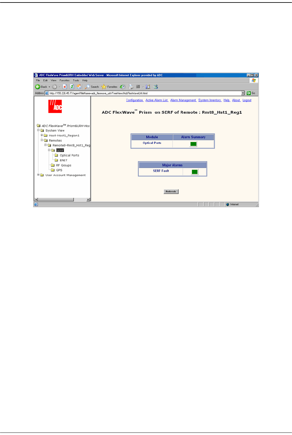
The
Prism on SERF of Remote
-n view provides an alarm summary for the SeRF card on
the identified Remote.
•
Optical Ports
status indicator—Summary alarm status indicator for Remote optical
ports. Red indicates no light (such as the RxNolight Fault) or a laser fault.
•
SERF Fault
status indicator—Summary alarm status indicator for Remote SeRF
card. Red indicates that an alarm exists for the Remote SeRF card.
10.9 VIEWING REMOTE SERF OPTICAL PORTS
The
Optical Ports On Remote
-n view shows the current usage and alarm status of the
optical ports on the Remote, plus current values of operating parameters. The
Optical
Ports On Remote
-n view only shows the ports that are in current use (that is, they have
a fiber and connector plugged into them with the other end of the fiber being
connected to Remote).
To open the
Optical Ports On Remote
-n view in the EMS View Frame, in the Function
Explorer Tree select
System View
,
Remotes
,
Remote#-
x,
SERF
,
Optical Ports
(where
Remote#
indicates the Remote number that corresponds to a Host SFP port number
and n is the Remote name).
Viewing Remote SeRF Optical Ports
FlexWave Prism Host, Remote and EMS 5.1 System Reference Page 249
ADCP-77-073 • Issue 2 • 11/2009 © 2009 ADC Telecommunications, Inc.
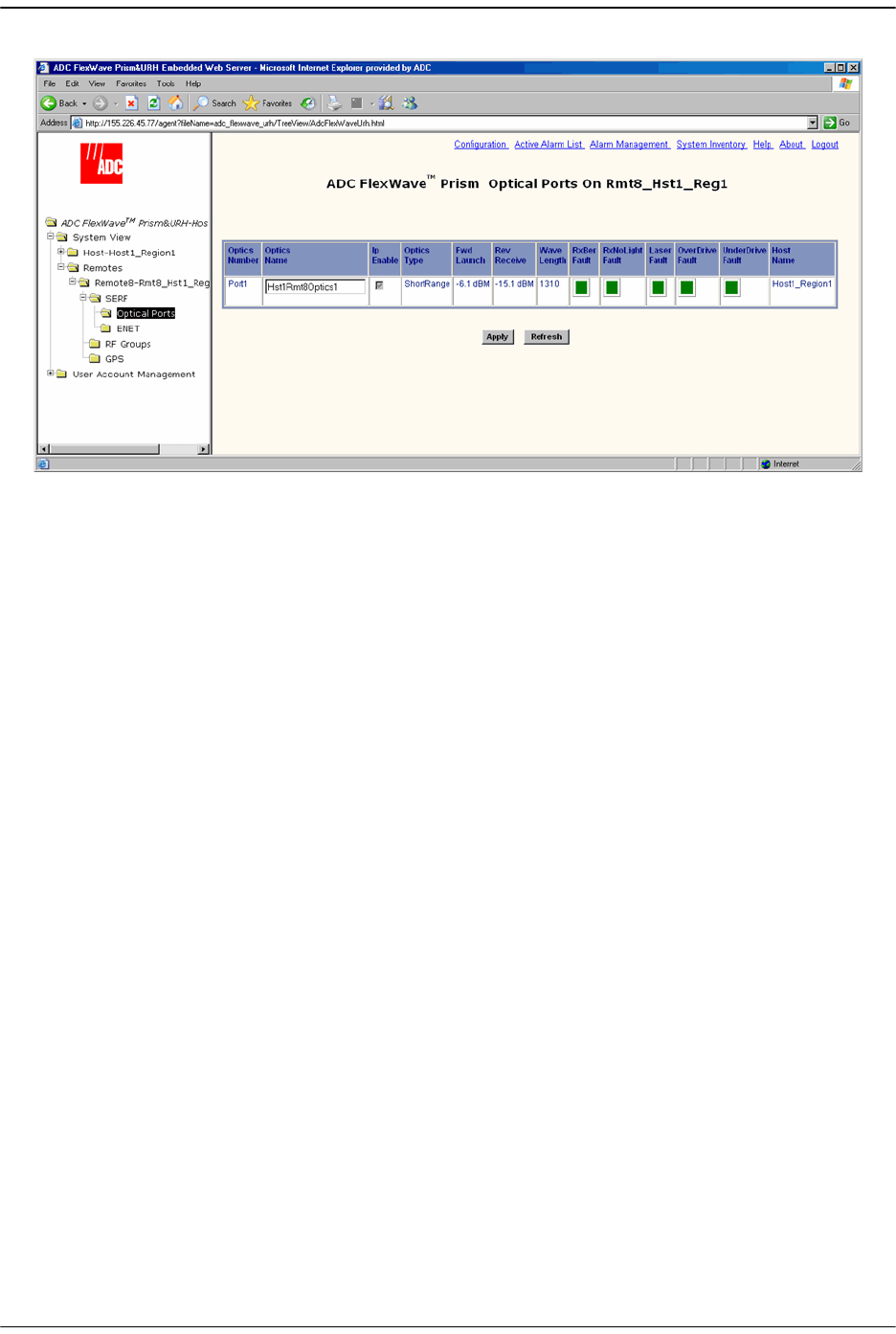
The
Optical Ports On Remote
-n view provides an alarm summary for the SeRF card on
the identified Remote.
•
Optics Number
—System-assigned port number and link to the
Port Configuration
Page
for this particular port
•
Optics Name
—User-entered port name or
UNKNOWN_SFPName
indicating no name
has been entered
•
Ip Enable
—Disabled for Remotes. This parameter indicates if the link is carrying IP
traffic. It can only be set on the Host as described in “Configure the Remote SeRF
Optical Ports” on page 158.
•
Optics Type
—Laser range, which is
LongRange
to meet 3Gbps optical transmission
requirements.
•
Fwd Launch
—Launch power in dB of REV path signal, from the Remote to the Host.
•
Rev Receive
—Launch power in dB of receive level of the FWD path, from the Host
to the Remote. The minimum REV launch power is -27 dBm, and the maximum is
-9 dBm.
•
Wave Length
—Number displayed is wave length transmitted through this port
•
RxBer Fault
—Yellow indicates that there ware too many errors on the receiving
fiber. Fault threshold is
0.00001
.
•
RxNoLight Fault
—Red indicates that no light is detected on the receiving fiber
•
Laser Fault
—Red indicates reverse path laser is not sending light
•
OverDrive Fault
—Red indicates forward path optical signal is too strong. Fault
threshold is
-9dBm
.
•
UnderDrive Fault
—Yellow indicates forward path optical signal is too weak. The
underdrive is from -28dBm to -33dBm. Fault threshold is
-27dBm
.
•
Host Name
—Name of the Host at the other end of the fiber.
Managing Remote Units
Page 250 FlexWave Prism Host, Remote and EMS 5.1 System Reference
© 2009 ADC Telecommunications, Inc ADCP-77-073 • Issue 2 • 11/2009
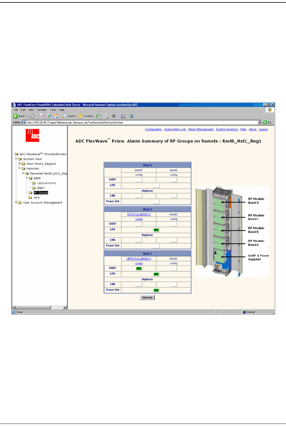
10.10 VIEWING AN ALARM SUMMARY OF THE REMOTE RF
GROUPS
The
Alarm Summary of RF Groups of Remote-
n view provides an alarm summary for the
four RF groups on a particular Remote (
Remote-
n).
To open the
Alarm Summary of RF Groups of Remote-
n view in the EMS View Frame, in
the Function Explorer Tree select
System View
,
Remotes
,
Remote#-
x,
RF Groups
(where
Remote#
indicates the Remote number that corresponds to a Host SFP port number
and n is the Remote name).
To understand how the EMS maps the RF Groups in the Remote to their
representation in the GUI, see “RF Groups in the Remote and the EMS GUI” on
page 160. The RF Group alarm indicators are listed below.
•
DART
—Summary alarm state of the DART card upconverter, downconverter and
the DART FPGA. Yellow indicates that a Minor alarm is the highest-level alarm and
Red indicates that a Major alarm exists for the DART.
•
LPA
—Summary alarm state of Linear Power Amplifier (LPA), where both LPA
indicators refer to the same LPA. Yellow indicates that a Minor alarm is the
highest-level alarm and Red indicates that a Major alarm exists for the LPA.
Viewing an Alarm Summary of the Remote RF Groups
FlexWave Prism Host, Remote and EMS 5.1 System Reference Page 251
ADCP-77-073 • Issue 2 • 11/2009 © 2009 ADC Telecommunications, Inc.
•
LNA
—Summary alarm state of the Low Noise Amplifier (LNA). Red indicates that
an active alarm exists for the LNA.
•
Power Det
—Red indicates that the LPA has been shut down. On initial
configuration, the
Power Det
indicator will be red until the link is created.
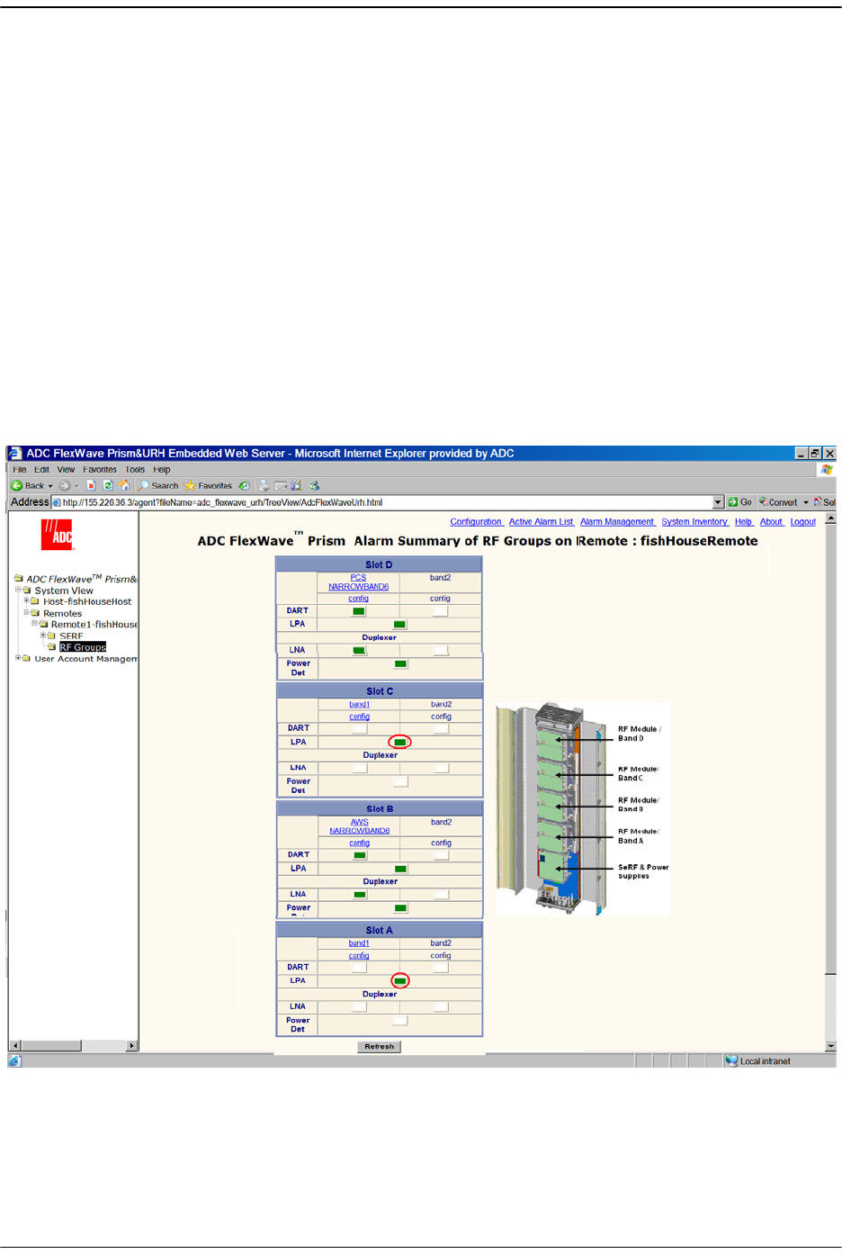
When a new dual-slot 40W RF Module is installed in a Prism system, in the
Alarm
Summary of RF Groups on Remote
window, the status of the second LPA is in the slot
below where the DART appears in the GUI.
The following figure shows:
•• 40W RF Module, PCS 1900 Non-Diversity Enclosure for Prism Remote installed in
Slots D and C. The second LPA status is shown in Slot C.
•• 40W RF Module AWS 2100 Non-Diversity Enclosure for Prism Remote installed in
Slots B and A. The second LPA status is shown in Slot A.
Managing Remote Units
Page 252 FlexWave Prism Host, Remote and EMS 5.1 System Reference
© 2009 ADC Telecommunications, Inc ADCP-77-073 • Issue 2 • 11/2009
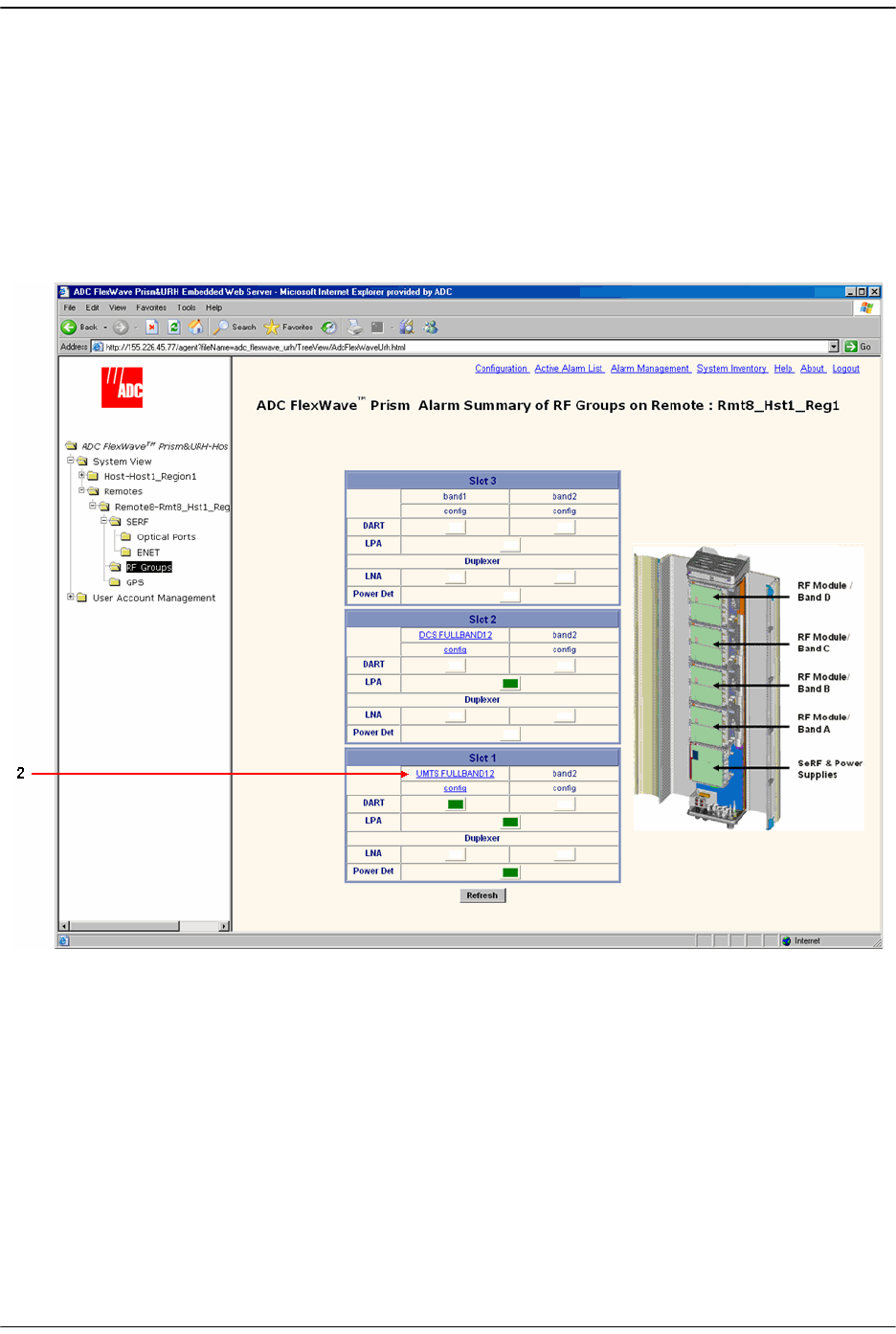
10.11 VIEWING RF BAND ALARM DETAILS
The
Alarm Summary of RF Groups of Remote-
n view shows band-specific alarm
indicators and their current values.
11 To open the
Alarm Summary of RF Groups of Remote-
n view in the EMS View Frame,
in the Function Explorer Tree select
System View
,
Remotes
,
Remote#-
x,
RF Groups
(where
Remote#
indicates the Remote number that corresponds to a Host SFP port
number and n is the Remote name).
Viewing RF Band Alarm Details
FlexWave Prism Host, Remote and EMS 5.1 System Reference Page 253
ADCP-77-073 • Issue 2 • 11/2009 © 2009 ADC Telecommunications, Inc.
22 Click on a
DART
band in the RF Groups view (upper link) to open the
Alarm Details
of DART-
n
of Group
n
on Remote-
n window.
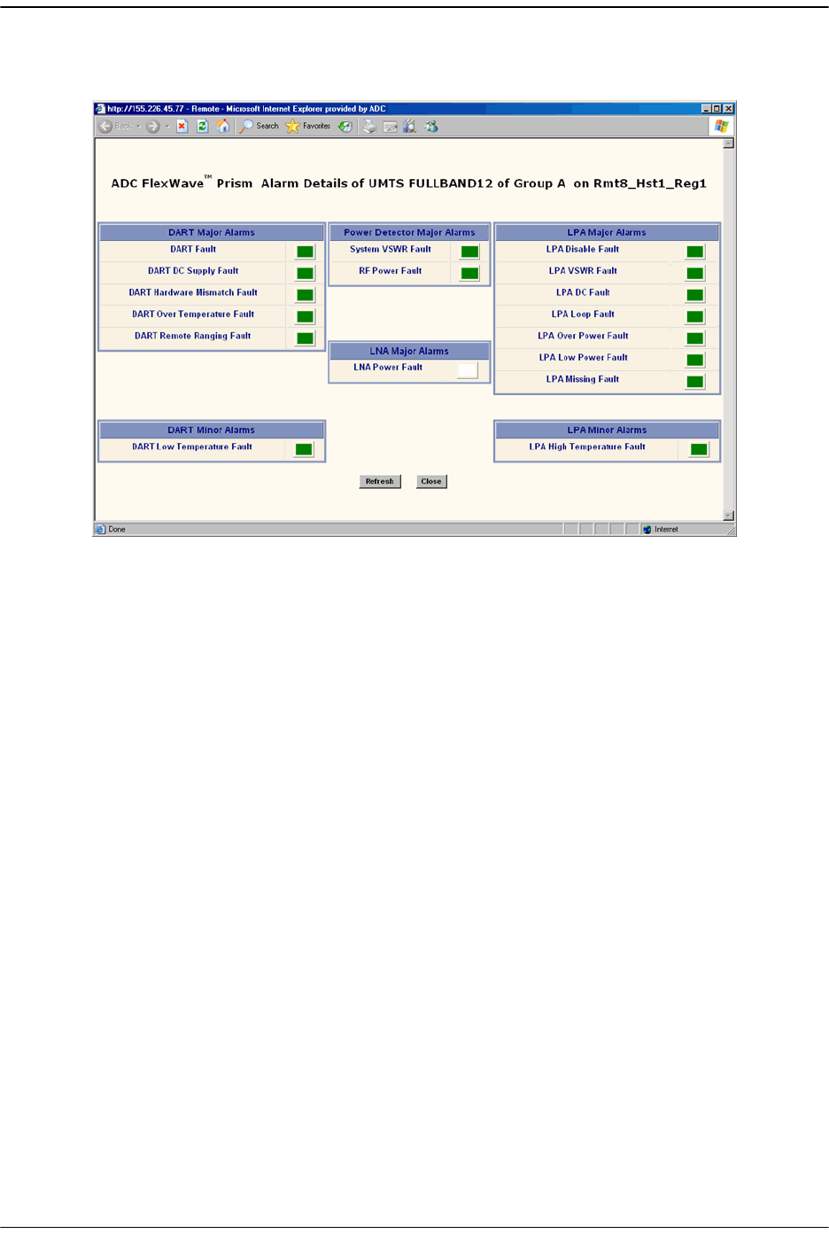
The
Alarm Details of DART-
n
of Group
n
on Remote-
n window has the the following
components. For corrective actions for alarm states, refer to “Troubleshooting
Alarms” on page 264.
• DART Major Alarms
–
DART Fault
—Summary alarm state of the DART card upconverter
downconverter and the DART FPGA. Red indicates that either the clock
source for the DART card is outside the acceptable range or the DART FPGA
is not programmed.
–
DART DC Supply Fault
—Red indicates DART card DC supply is faulted.
–
DART Hardware Mismatch Fault
—Red indicates an invalid passband
configuration for the DART.
–
DART Over Temperature Fault
—Red indicates DART card internal
temperature is too high. Fault threshold is
84°C
.
–
DART Remote Ranging Fault
—Red indicates that the Host is unable to
implement the signal delay entered in the RF Band Configuration Page
(described in “Link the Host and Remote DARTs.” on page 159).
• Power Detector Major Alarms
–
System VSWR Fault
—Red indicates a VSWR fault at the interface to the
antenna (greater than 3:1).
–
RF Power Fault
—Red indicates that the RF power measured at the antenna
output is too low. The threshold for this fault is
0 dBm
.

Managing Remote Units
Page 254 FlexWave Prism Host, Remote and EMS 5.1 System Reference
© 2009 ADC Telecommunications, Inc ADCP-77-073 • Issue 2 • 11/2009
• LNA Major Alarms
–
LNA Power Fault
—Red indicates that the Low Noise Amplifier has an internal
error.
• LPA Major Alarms
–
LPA Disable Fault
—Red indicates that the Linear Power Amplifier is disabled
because it encountered a problem.
–
LPA VSWR Fault
—Red indicates that an internal VSWR fault state of the LPA.
Fault threshold is
2
.
–
LPA DC Fault
—Red indicates that the voltage level inside the LPA is outside
its acceptable range.
–
LPA Loop Fault
—Red indicates that the feedback loop inside the LPA is not
working.
–
LPA Over Power Fault
—Red indicates that the power level inside the LPA is
high enough to damage the LPA.
–
LPA Low Power Fault
—Red indicates that the internal gain of LPA does does
not meet specification.
–
LPA Missing Fault
—Red indicates that the LPA is missing.
• DART Minor Alarms
–
DART Low Temperature Fault
—Yellow indicates DART temperature is too low.
Fault threshold is
-40°C
.
• LPA Minor Alarms
–
LPA High Temperature Fault
—Yellow indicates that the LPA internal
temperature is too high.
Viewing Remote GPS Alarms and Location Parameters
FlexWave Prism Host, Remote and EMS 5.1 System Reference Page 255
ADCP-77-073 • Issue 2 • 11/2009 © 2009 ADC Telecommunications, Inc.
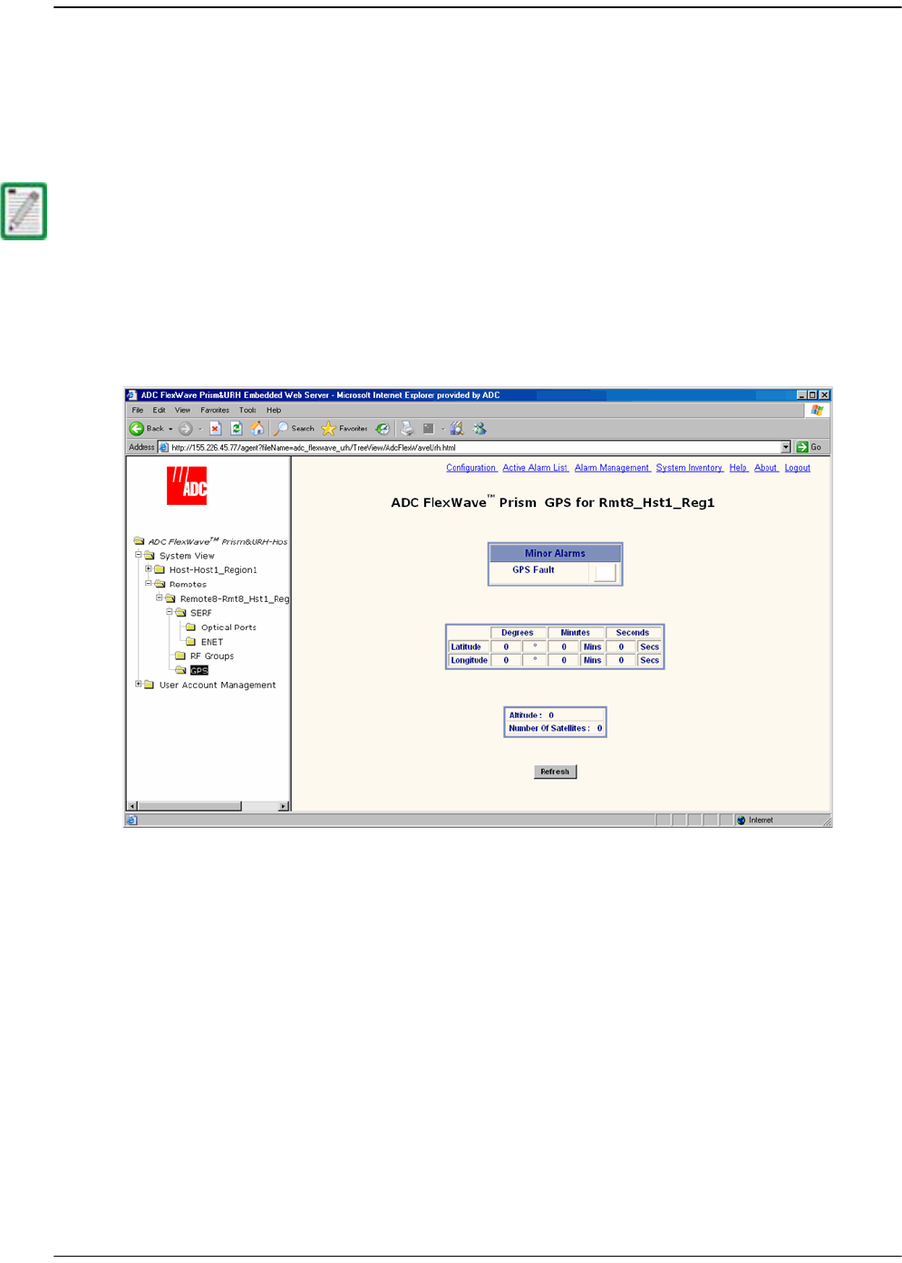
10.12 VIEWING REMOTE GPS ALARMS AND LOCATION
PARAMETERS
The
Remote GPS
(Global Positioning System) page shows the alarm status and location
parameters for the Remote GPS function.
To open the GPS summary in the EMS View Frame, in the Function Explorer Tree select
System View
,
Remotes
,
Remote#-
x,
GPS
(where
Remote#
indicates the Remote number
that corresponds to a Host SFP port number and n is the Remote name).
GPS is not supported in the software version documented in this manual so the Remote
GPS page components are not described.

Managing Remote Units
Page 256 FlexWave Prism Host, Remote and EMS 5.1 System Reference
© 2009 ADC Telecommunications, Inc ADCP-77-073 • Issue 2 • 11/2009
Intentionally Blank Page

FlexWave Prism Host, Remote and EMS 5.1 System Reference Page 257
ADCP-77-073 • Issue 2 • 11/2009 ©2009 ADC Telecommunications, Inc.
11 MANAGING ALARMS
11.1 Viewing Active Alarms .....................................................................................258
11.2 Viewing an Alarm History Log...........................................................................259
11.3 Masking an Alarm Type ...................................................................................260
11.4 Unmasking an Alarm Type ...............................................................................262
11.5 Troubleshooting Alarms...................................................................................264
Some EMS parameter values are associated with alarms. When a parameter enters an
alarm state, an alarm status indicator is activated where the color of the indicates the
alarm severity, where:
•• Red indicates a major alarm
•• Yellow indicates a minor alarm
•• Green indicates a normal (okay) state
•• Grey indicates that the alarm has been masked
•• White indicates that an associated device is unplugged or missing.
Content Page
Managing Alarms
Page 258 FlexWave Prism Host, Remote and EMS 5.1 System Reference
© 2009 ADC Telecommunications, Inc ADCP-77-073 • Issue 2 • 11/2009
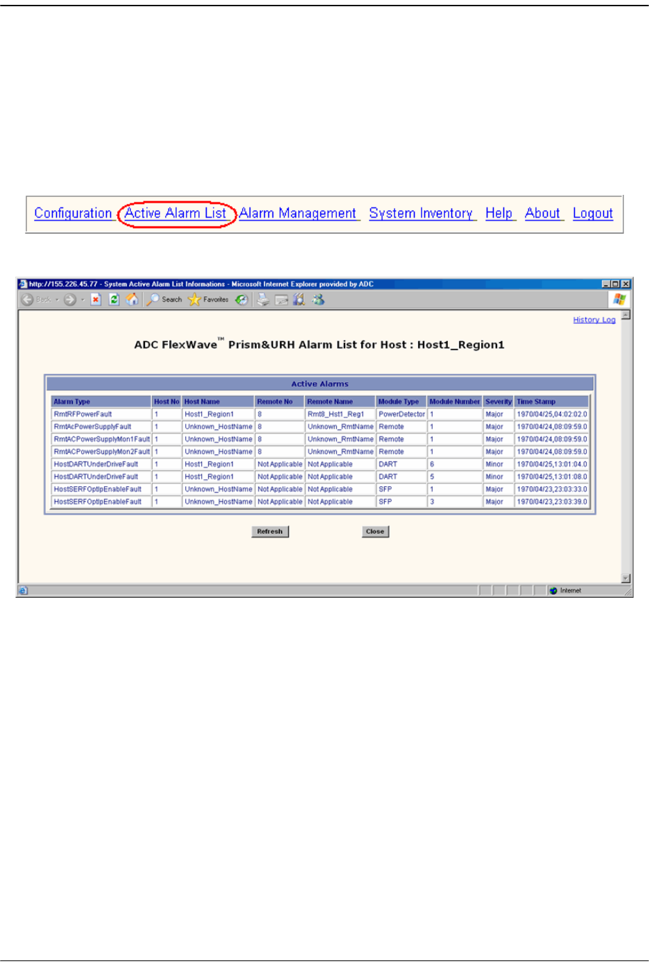
11.1 VIEWING ACTIVE ALARMS
Viewing the
Active Alarm List
window is a means to determine alarm type, Host unit
name, Remote name, time stamp, and other information for active alarms.
11 To access the EMS Menu bar, in the Function Explorer Tree, click on
System View
to
display a system view.
22 To open the
Active Alarm List
window, in the EMS Menu bar select
Active Alarm List
.
The
Active Alarm List
table provides the following information:
•
Alarm Type
—Descriptive name of alarm. For more information, refer to
“Troubleshooting Alarms” on page 264.
•
Host No
—Always “
1
”
•
Host Name
—User-defined Host name or system default
•
Remote No
—System assigned number of Remote from which alarm came
•
Remote Name
—User-defined Remote name or system default
•
Module Type
—Type of unit that is experiencing the alarm (SeRF, DART, LPA, LNA,
Power Detector, SFP)
•
Module Number
—Unit number of module experiencing the alarm condition
•
Severity
—
Major
or
Minor
•
Time Stamp
—Date and time when the alarm occurred (
YYYY:MM:DD:HH:MM:SS
)
Viewing an Alarm History Log
FlexWave Prism Host, Remote and EMS 5.1 System Reference Page 259
ADCP-77-073 • Issue 2 • 11/2009 © 2009 ADC Telecommunications, Inc.
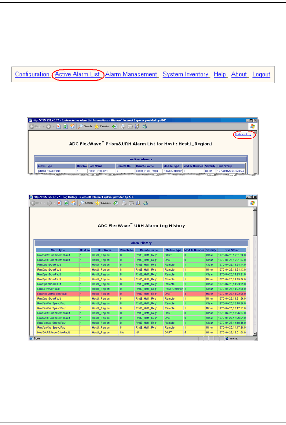
11.2 VIEWING AN ALARM HISTORY LOG
11 To access the EMS Menu bar, in the Function Explorer Tree, click on
System View
to
display a system view.
22 To open the
Active Alarm List
window, in the EMS Menu bar select
Active Alarm List
.
33 To open the
Alarm Log History
window, in the
Active Alarm List
window click the
History Log
link.
The
Alarm Log History
window components are the same as for the
Active Alarm List
window (see “Viewing Active Alarms” on page 258), except the
Alarm Log History
window includes the severity of
Clear
if the alarm condition has been cleared.
Managing Alarms
Page 260 FlexWave Prism Host, Remote and EMS 5.1 System Reference
© 2009 ADC Telecommunications, Inc ADCP-77-073 • Issue 2 • 11/2009
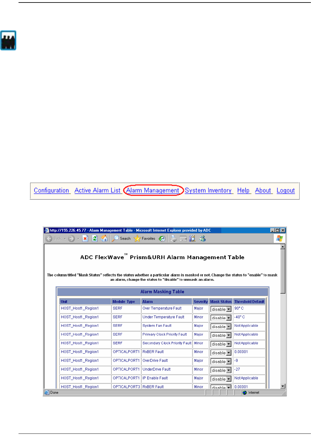
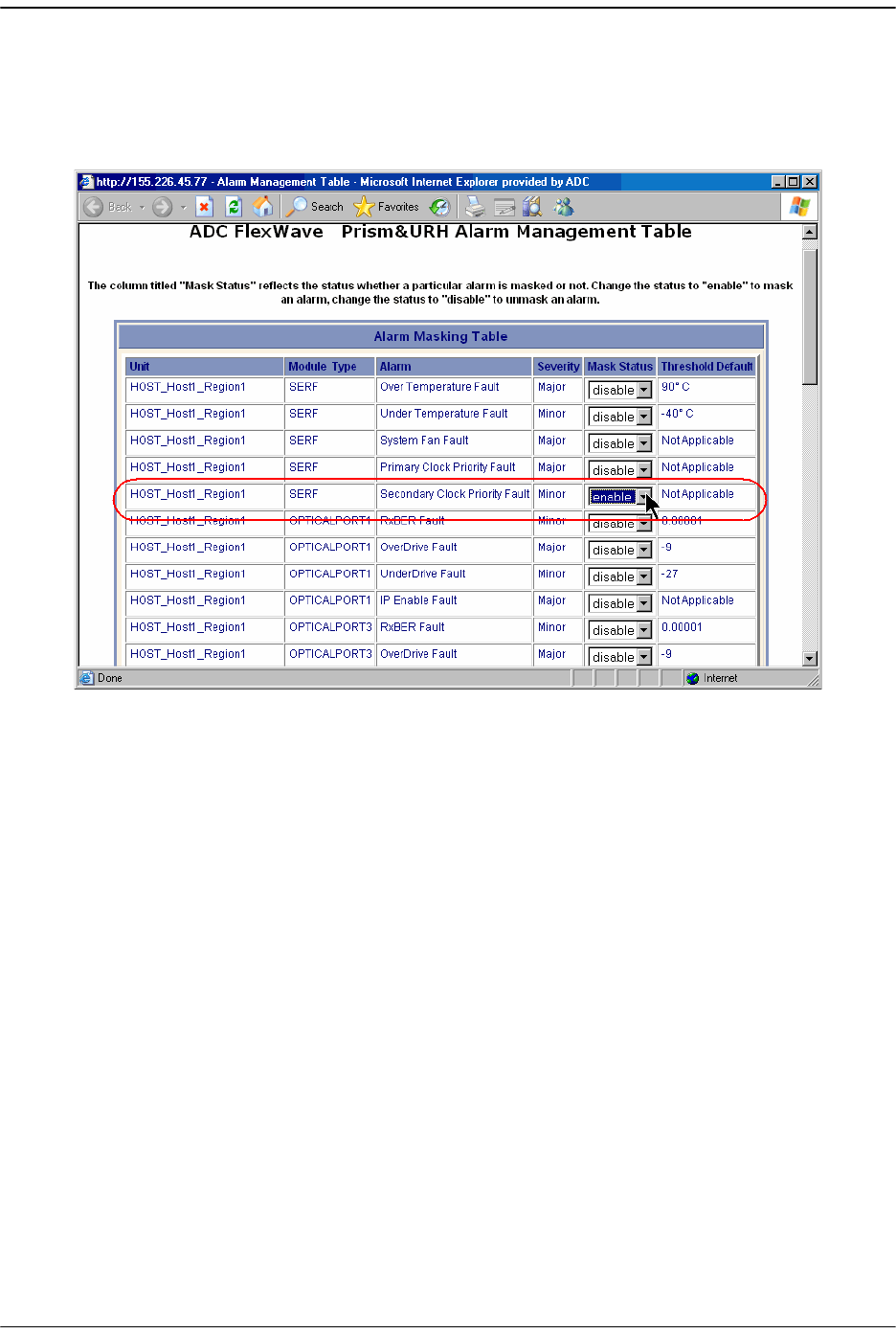
11.3 MASKING AN ALARM TYPE
Masking an alarm type causes the EMS to stop reporting alarms of that type until the
alarm is unmasked. By default all alarms are unmasked. When an alarm type is
masked (mask status enabled), the following is true:
•• The corresponding status indicator shows in gray.
•• The alarm state is not calculated into the higher level alarm summary
•• The corresponding trap is not sent to SNMP managers.
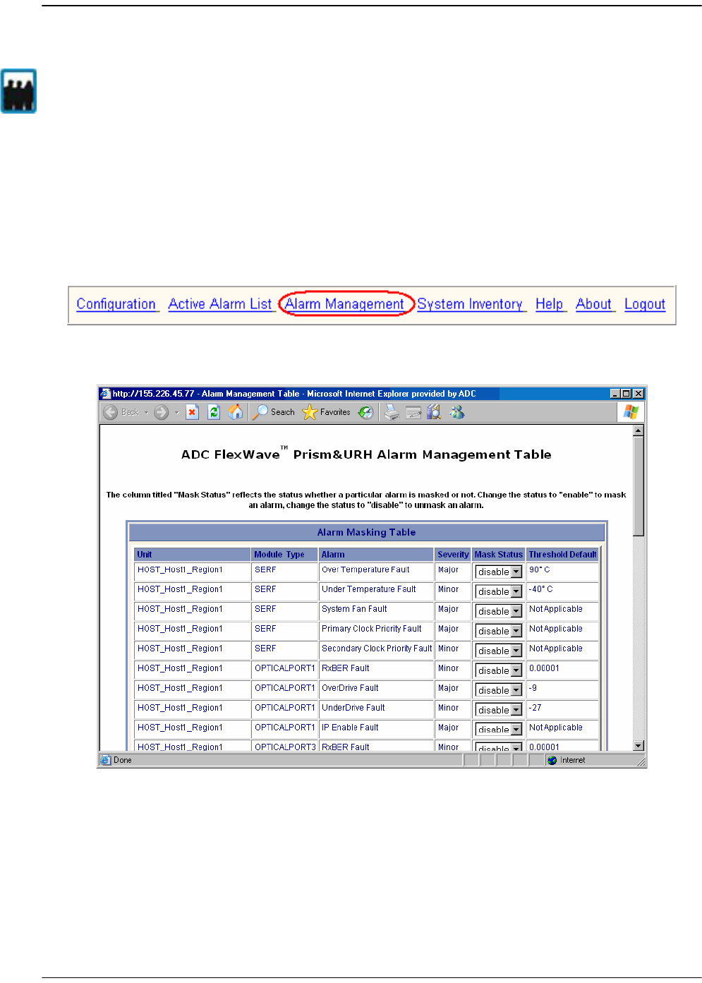
To mask an alarm:
11 To access the EMS Menu bar, in the Function Explorer Tree, click on
System View
to
display a system view.
22 In the EMS Menu bar, select
Alarm Management
.
The
Alarm Management Tabl
e window opens.
Only a user logged in under the admin or a Network Manager account can change Prism
system settings through the EMS.
Masking an Alarm Type
FlexWave Prism Host, Remote and EMS 5.1 System Reference Page 261
ADCP-77-073 • Issue 2 • 11/2009 © 2009 ADC Telecommunications, Inc.
33 Click the list in the Mask Status column for the alarm for which you want to enable
a mask, select
enable
, and then click
Apply
.
In the following graphic, a mask has been enabled for the SeRF Secondary Clock
Priority Fault.
Managing Alarms
Page 262 FlexWave Prism Host, Remote and EMS 5.1 System Reference
© 2009 ADC Telecommunications, Inc ADCP-77-073 • Issue 2 • 11/2009
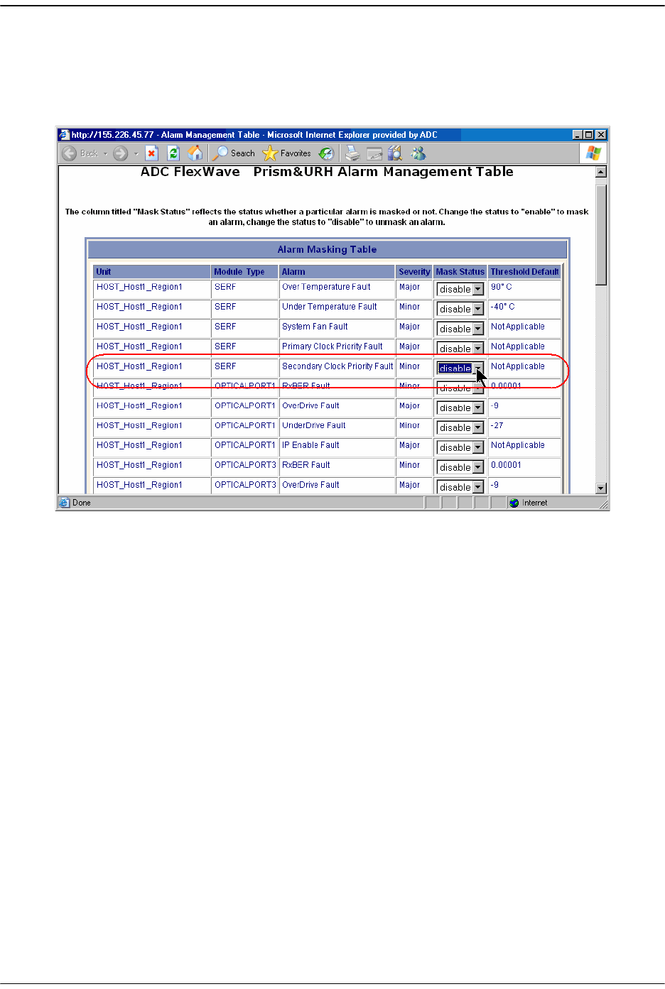
11.4 UNMASKING AN ALARM TYPE
Unmasking an alarm type causes the EMS to report alarms of that type until the alarm
is masked. By default all alarms are unmasked.
11 To access the EMS Menu bar, in the Function Explorer Tree, click on
System View
to
display a system view.
22 In the EMS Menu bar, select
Alarm Management
.
The
Alarm Management Tabl
e window opens.
Only a user logged in under the admin or a Network Manager account can change Prism
system settings through the EMS.
Unmasking an Alarm Type
FlexWave Prism Host, Remote and EMS 5.1 System Reference Page 263
ADCP-77-073 • Issue 2 • 11/2009 © 2009 ADC Telecommunications, Inc.
33 Click the list in the Mask Status column for the alarm for which you want to
disable a mask, select
disable
, and then click
Apply
.
In the following graphic, masking has been disabled for the SeRF Secondary Clock
Priority Fault.

Managing Alarms
Page 264 FlexWave Prism Host, Remote and EMS 5.1 System Reference
© 2009 ADC Telecommunications, Inc ADCP-77-073 • Issue 2 • 11/2009
11.5 TROUBLESHOOTING ALARMS
This section lists alarms that can be viewed in EMS alarm summaries.
Table 11-1. EMS Alarm Descriptions and Corrective Actions
Alarm Name Alarm
Severity
Level
Description Action
HostDARTDCSupplyFault
Major The voltage supplied
to the DART board is
too low. (Host DC
Power board accepts
21-60 Vdc and draws
up to 427.28 Watts
per Host.)
Check whether the
Vdc supply is in the
range of 21-60 Vdc.
If persistent (may be
transient on
startup), contact
ADC.
HostDARTDwnCon1SynLockFault
Major Lock state of the
first down converter
synthesizer. Causes
RF mute
When a DART is
being turned up or
after a power reset,
the DART
synthesizers may go
in and out of lock,
which may cause
this fault. Unless
this fault persists,
these transient
faults can be
ignored. If
persistent, consult
ADC, replace DART
HostDARTDwnCon2SynLockFault
Major Lock state of the
second
downconverter
synthesizer. Causes
RF mute
When a DART is
being turned up or
after a power reset,
the DART
synthesizers may go
in and out of lock,
which may cause
this fault. Unless
this fault persists,
these transient
faults can be
ignored. If
persistent, consult
ADC, replace DART

Troubleshooting Alarms
FlexWave Prism Host, Remote and EMS 5.1 System Reference Page 265
ADCP-77-073 • Issue 2 • 11/2009 © 2009 ADC Telecommunications, Inc.
HostDARTFault
Major Summary status of
DART upconverter
and/or
downconverter and
DART FPGA status.
The clock source for
the DART is outside
an acceptable range
or the DART FPGA is
not programmed.
may also occur with
the
DARTDCSupplyFault.
Inspect
Active
Alarm List
for
upconverter and/or
downconverter
alarms. If these
alarms are found
and persist, consult
ADC, replace DART.
If no
upconverter/downc
onverter alarms are
found, unplug DART
from Host, then
replug DART in Host
to reload the FPGA. If
persistent, consult
ADC, replace DART.
HostDARTHardwareMismatchFault
Major Indicates a hardware
mismatch for the
DART boards
between linked Host
and Remote
Check if a linked
DART of one type
was unplugged and
not decommissioned
then replaced with a
DART of another
type. Make sure
linked Host and
Remote DARTs are
of same type
HostDARTOverDriveFault
Major the RF signal
received from BTS is
greater than +5dBm.
The allowed range is
-25 dBm to +5 dBm.
Lower the gain on
the Host DART. If
persistent when
gain is zero, lower
power of BTS RF
signal. Maximum
power at zero gain is
+19dBm.
HostDARTUnderDriveFault
Minor When the Host input
level is 20 dB less
than the expected
Host DART Input. For
example, for 30 dB of
Host DART gain (-25
dBm expected input),
the threshold is -45
dBm. For 0 dB of
Host DART gain (+5
dBm expected input),
the threshold is -15
dBm.
Increase the gain of
the Host DART. If
persistent when
gain is at maximum,
increase power of
BTS RF signal.
HostDARTUpConSynLockFault
Major Lock state of the
upconvertor
synthesizer
If persistent, consult
ADC, replace DART
Table 11-1. EMS Alarm Descriptions and Corrective Actions (Cont.)
Alarm Name Alarm
Severity
Level
Description Action

Managing Alarms
Page 266 FlexWave Prism Host, Remote and EMS 5.1 System Reference
© 2009 ADC Telecommunications, Inc ADCP-77-073 • Issue 2 • 11/2009
HostModuleMissingFault
Major One of the pluggable
modules is missing
on the Host
Either insert a
replacement unit or
decommission the
unit
HostOverTempFault
Major The temperature of
the Host is Over its
upper limit of 84C
Check Host fan and
ambient conditions
HostSERFFault
Major Summary fault for
SeRF combining
SeRF synthesizer
and SeRF FPGA
status. Either the
clock source is not
acceptable or the
SeRF board FPGA is
not programmed.
Check for related
SeRF alarms in
Active Alarm List
and respond to
those alarms if
found. If no SeRF
alarms exists, FPGA
is faulty; consult
ADC, replace SeRF. If
SeRF is replaced, use
the same Compact
Flash to retain
system
configuration.
HostSERFOptOverDriveFault
Major The power of the
signal received from
the Remote exceeds
the maximum level
of -9dBm
Externally attenuate
Remote return path
signal or replace
Remote SFP with one
of less strength
HostSerfOptRxBerFault
Minor Too many errors on
the receiving fiber
Check fiber for kink
or sharp bend. Check
for too much gain.
Make sure the fiber
is clean.
HostSERFOptRxNoLightFault
Major No light detected
from the receiving
fiber
Check for broken or
disconnected fiber.
Check for out of
service Remote
HostSERFOptUnderDriveFault
Minor The power of the
signal received on
the fiber is below the
minimum power
level of -27dBm
Check fiber for too
much attenuation,
dirty connectors.
Check SFP type
being used (too
weak for range)
HostSERFRmtLostFault
Major Host is not receiving
messages from
connected Remote
or there is an IP
conflict causing loss
of communication
Check for optics
disconnect. Check
for Remote out of
power or out of
service
Check for IP conflict
Table 11-1. EMS Alarm Descriptions and Corrective Actions (Cont.)
Alarm Name Alarm
Severity
Level
Description Action

Troubleshooting Alarms
FlexWave Prism Host, Remote and EMS 5.1 System Reference Page 267
ADCP-77-073 • Issue 2 • 11/2009 © 2009 ADC Telecommunications, Inc.
HostSERFSynthAlarmFault
Major The configured clock
source is not
providing an
acceptable signal
If clock source is
onboard and
persists, consult
ADC, replace system
card. If clock source
is external, check
clock source,
connection
HostSysCardFanFault
Major The Host fan is
spinning too slowly
Check fan for
mechanical problem.
If not fixable,
consult ADC, replace
fan
HostUnderTempFault
Minor The temperature of
the Host is under its
lower operating limit
(-40 degrees
Fahrenheit )
Check ambient
conditions
RmtAcPowerSupplyFault
,
RmtACPowerSupplyMon1Fault
Major A power supply is in
a failed state
If persistent, consult
ADC, may have to
replace one or more
power supply
located in the SeRF
Module
RmtDARTDCSupplyFault
Major The on-board DC
voltages are out of
their valid ranges
If persistent (may be
transient on
startup), check If the
DC power switch to
the DART is in the
OFF position. If DC
power is ON, reset
set the RF Module. If
the alarm persists,
consult ADC, as you
may have to replace
RF Module
RmtDARTDwnCon1SynLockFault
Major Lock state of the
first downconverter
synthesizer
If persistent, consult
ADC, replace RF
Module
RmtDARTDwnCon2SynLockFault
Major Lock state of the
second
downconverter
synthesizer
If persistent, consult
ADC, replace RF
Module
RmtDARTFault
Major Summary fault
status of DART
upconvertor/
downconverter and
DART FPGA status
If persistent, consult
ADC, replace RF
Module
Table 11-1. EMS Alarm Descriptions and Corrective Actions (Cont.)
Alarm Name Alarm
Severity
Level
Description Action

Managing Alarms
Page 268 FlexWave Prism Host, Remote and EMS 5.1 System Reference
© 2009 ADC Telecommunications, Inc ADCP-77-073 • Issue 2 • 11/2009
RmtDARTHardwareMismatchFault
Major Indicates a hardware
mismatch for the
DART cards between
linked Host and
Remote
Check if a linked
DART of one type
was unplugged and
not decommissioned
then replaced with a
DART of another
type. Make sure
linked Host and
Remote DARTs are
of same type
RmtDARTOverTempFault
Major Indicates that
detected
temperature is
above the maximum
ambient
temperature of 50°C.
Check air flow
around Remote. If
persists, consult
ADC.
RmtDARTUnderTempFault
Minor Indicates that
detected
temperature is
below the lower
acceptable limit (-40
degrees Farenheit)
Check ambient
conditions
RmtDARTUpConSynLockFault
Major Lock state of the
upconverter
synthesizer
If persistent, consult
ADC, replace RF
Module
RmtLNAPowerFault
Major The low noise
amplifier has an
internal error
If persistent, consult
ADC, replace RF
Module
RmtLPADcFault
Major The LPA voltage
level is outside its
acceptable range.
Causes RF mute
Reset LPA and
recheck. If alarm
keeps coming back,
consult ADC, replace
RF Module
RmtLPADetectFault
Major Presence fault state
of the LPA (the LPA
cannot be detected)
If persistent, consult
ADC, replace RF
Module
RmtLPADisableFault
Major Disable state of the
LPA. The LPA is
disabled because it
encountered a
problem
See “Identify the LPA
Fault” on page 236.
If fault cannot be
corrected, replace
the RF Module
RmtLPAHighTempFault
Minor LPA is overheated Check ambient
temperature. Check
remote temperature.
Reset LPA. If
persistent, consult
ADC, replace RF
Module
Table 11-1. EMS Alarm Descriptions and Corrective Actions (Cont.)
Alarm Name Alarm
Severity
Level
Description Action

Troubleshooting Alarms
FlexWave Prism Host, Remote and EMS 5.1 System Reference Page 269
ADCP-77-073 • Issue 2 • 11/2009 © 2009 ADC Telecommunications, Inc.
RmtLPALoopFault
Major The feedback loop
inside the LPA is not
working. Causes RF
mute
Lower DART(s)
remote gain by 10dB,
reset the LPA, then
return gain to values
previously
configured. If fault
persists, replace RF
Module.
RmtLPALowPowerFault
Major Internal low power
fault state of linear
power amplifier (the
gain of one or more
internal amplifiers
does not meet
specification).
Causes RF mute
Reset LPA. If error
persists, consult
ADC, replace RF
Module
RmtLPAOverPowerFault
Internal over power
fault state of linear
power amplifier
(power level is high
enough to damage
LPA)
Reduce FWD gain,
reset the LPA, and
then monitor power
levels. Adjust gain to
acceptable values.
Reset LPA. If error
persists, consult
ADC, replace RF
Module
RmtLPAVswrFault
Major Internal VSWR fault
state of linear power
amplifier (greater
than 3:1). Causes RF
mute
Reset LPA. If error
persists, consult
ADC, replace RF
Module
RmtMajorExtAlarmInputFault
Major External major alarm
contact input
Not used
RmtMinorExtAlarmInputFault
ALARM-
TYPE
(Minor,
OK)
External minor alarm
contact input
Not used
RmtModuleMissingFault
Major One of the pluggable
modules is missing
on the Remote
Replace or
decommission the
missing module
Table 11-1. EMS Alarm Descriptions and Corrective Actions (Cont.)
Alarm Name Alarm
Severity
Level
Description Action

Managing Alarms
Page 270 FlexWave Prism Host, Remote and EMS 5.1 System Reference
© 2009 ADC Telecommunications, Inc ADCP-77-073 • Issue 2 • 11/2009
RmtNoRFPowerFault
Major The RF power
measured at the
antenna output is
too low. The
threshold for this
fault is 0 dBm.
Verify that there is
an active Host DART
Under Drive Fault,
which indicates a
loss of BTS input. If
this fault is active,
address this
problem and the
RmtNoRFPowerFault
should clear.
If there is not an
active Host DART
Under Drive Fault,
the problem may be
the result of another
LPA fault such as
VSWR or Over Power
Faults. If there are no
other faults, then
reset the Remote RF
Module. If power is
still not, present
then replace the
module.
RmtOverTempFault
Major High temperature
reading from RSI
card in Remote
Check ambient
temperature. Check
remote temperature.
If not an actual over
temperature fault,
shut down Remote,
consult ADC
RmtRangingFault
Major The configured
delay is outside the
range of what can be
supplied.
Enter a delay value
within the
permissible range
see “Link a Remote
DART to a Host
DART” on page 162
RmtSERFFault
Major Summary fault for
SeRF combining
SeRF synthesizer
and SeRF FPGA
status
Check for related
SeRF alarms in active
alarms list and
respond to those
alarms if found. If no
SeRF alarm exists,
FPGA is faulty;
consult ADC, replace
SeRF
Table 11-1. EMS Alarm Descriptions and Corrective Actions (Cont.)
Alarm Name Alarm
Severity
Level
Description Action

Troubleshooting Alarms
FlexWave Prism Host, Remote and EMS 5.1 System Reference Page 271
ADCP-77-073 • Issue 2 • 11/2009 © 2009 ADC Telecommunications, Inc.
RmtSERFHstLostFault
Major Remote not
receiving any
messages from
connected Host
There are two
possible actions:
•Check for optics
disconnect. Check
the optical link
and determine the
source of lost
communications.
If an optical meter
on the output of
the SFP
determines that
no power is being
transmitted, or
meter measuring
receive levels at
the SFP
determines the
receiver is broken,
replace SFP with
the appropriate
type for the range
of signal
supported.
•There may be an
IP conflict. For
example, if the
Host is configured
in External
Network mode but
there's not a DHCP
server running on
the network, the
Remote will not
receive an IP
address, there
therefore will not
be communication
with the Host,
which would
activate this
alarm.
RmtSERFOptLaserFault
Major SFP reports that
laser of forward
path is faulty
Replace SFP with the
appropriate type for
range of signal
supported
RmtSERFOptOverDriveFault
Major The power of the
signal received at
the Remote is too
strong
Externally attenuate
Host forward path
signal or replace
Host SFP with one of
less strength
Table 11-1. EMS Alarm Descriptions and Corrective Actions (Cont.)
Alarm Name Alarm
Severity
Level
Description Action

Managing Alarms
Page 272 FlexWave Prism Host, Remote and EMS 5.1 System Reference
© 2009 ADC Telecommunications, Inc ADCP-77-073 • Issue 2 • 11/2009
RmtSERFOptRxBERFault
Minor Too many errors on
the receiving fiber
Check fiber for kink
or sharp bend. Check
for too much gain.
Make sure the fiber
is clean.
RmtSERFOptRxNoLightFault
Major No light detected
from the receiving
fiber
Check for broken or
disconnected fiber.
Check for out of
service Host
RmtSERFOptUnderDriveFault
Minor The power of the
signal received on
the fiber is too weak
Check fiber for too
much gain, dirty
connectors. Check
SFP type being used
(too weak for range)
RmtSERFSynthAlarmFault
Major Onboard
synthesizer fault
Check clock signal
coming from Host.
Host is not
generating a proper
signal. Possibly Host
clock source is bad
or Host has bad
FPGA
RmtSystemVswrFault
Major LPA VSWR Fault Perform cable
sweeps on external
antenna cable
system. Put a load on
the Remote by
disconnecting the
external antenna
cable to determine if
the source of the
VSWR condition is
internal or external.
If it's internal,
replace the RF
Module. If it's
external,
troubleshoot and
determine source of
high VSWR reading.
RmtUnderTempFault
Minor Temperature is
below lower
acceptable limit (-40
degrees Farenheit)
Check ambient
conditions
Table 11-1. EMS Alarm Descriptions and Corrective Actions (Cont.)
Alarm Name Alarm
Severity
Level
Description Action

Troubleshooting Alarms
FlexWave Prism Host, Remote and EMS 5.1 System Reference Page 273
ADCP-77-073 • Issue 2 • 11/2009 © 2009 ADC Telecommunications, Inc.
fwuHstSERFOptIpEnableFault
Major An attempt to enable
IP on a fiber (Host) to
a Remote that
already has IP
enabled on another
fiber (Host) has been
made.
The alarm is cleared
if IP is disabled on
the fiber. It is also
cleared if an ACK is
later received from
the Remote. This
latter condition can
occur if the fiber that
was already carrying
IP later has IP
disabled, or if the
fiber otherwise
becomes disabled.
For information on
setting Ip Enable,
see “Configure the
Remote SeRF Optical
Ports” on page 158
fwuRmtFanOverSpeedFault
Minor Remote fan has an
Over Speed fault
Fan may require
replacement.
fwuRmtFanUnderSpeedFault
Major Remote fan has an
Under Speed fault
Fan may require
cleaning and/or
replacement.
fwuRmtOpenDoorFault
Minor Door on the Remote
is open
Close the Remote
door
fwuHstSysCardPrimaryCPFault
Major Primary Clock
Priority Fault
Set Primary CPL
within acceptable
range
fwuHstSysCardSecondaryCPFault
Minor Secondary Clock
Priority Fault
Set Secondary CPL
within acceptable
range
Table 11-1. EMS Alarm Descriptions and Corrective Actions (Cont.)
Alarm Name Alarm
Severity
Level
Description Action

Managing Alarms
Page 274 FlexWave Prism Host, Remote and EMS 5.1 System Reference
© 2009 ADC Telecommunications, Inc ADCP-77-073 • Issue 2 • 11/2009

FlexWave Prism Host, Remote and EMS 5.1 System Reference Page 275
ADCP-77-073 • Issue 2 • 11/2009 ©2009 ADC Telecommunications, Inc.
12 SNMP INTERFACE
12.1 EMS SNMP Interface .......................................................................................276
12.2 SNMP Overview..............................................................................................277
12.2.1 Background Information on SNMP .............................................................278
12.2.2 MIB Used by FlexWave System .................................................................280
12.3 SNMP Procedures ...........................................................................................281
12.4 Accessing the FlexWave-Prism Agent MIB ..........................................................282
12.5 Configuring the Trap Viewer.............................................................................283
12.5.1 Registering the Manager for Receiving Traps
(static—non AdventNet MIB Browser) .............................................................283
12.5.2 Registering the Manager for Receiving Traps
(dynamic—AdventNet MIB Browser) ...............................................................284
12.5.3 Viewing Traps.........................................................................................287
12.5.3.1 Date and Time Stamps ....................................................................287
12.5.3.2 Variable Bindings ............................................................................288
12.5.3.3 View the Traps................................................................................290
12.6 FlexWave-URH Agent MIB................................................................................292
12.7 Traps ............................................................................................................308
Content Page
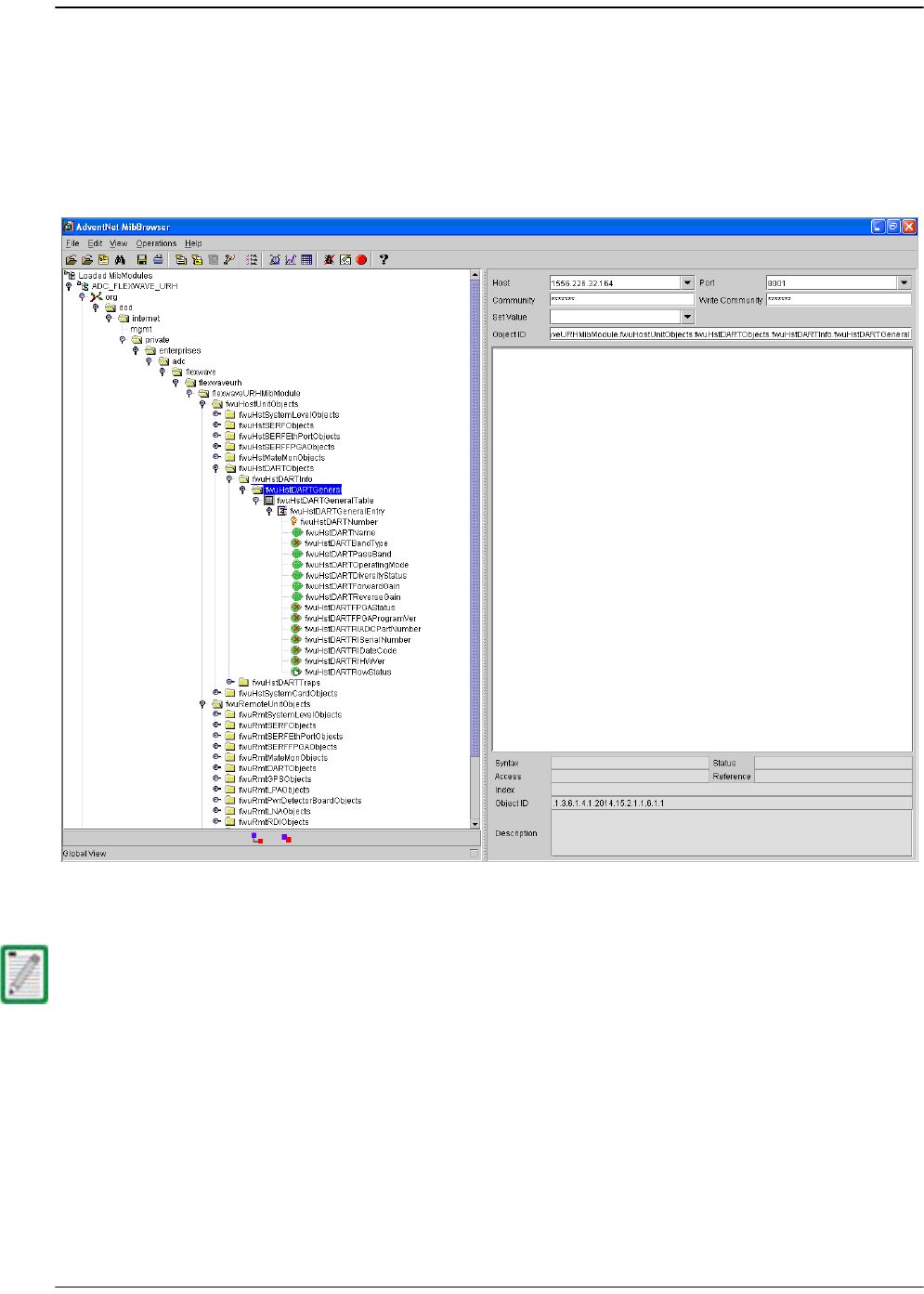
SNMP Interface
Page 276 FlexWave Prism Host, Remote and EMS 5.1 System Reference
© 2009 ADC Telecommunications, Inc ADCP-77-073 • Issue 2 • 11/2009
12.1 EMS SNMP INTERFACE
SNMP (Simple Network Management Protocol) is an international standard for remote
monitoring and control of online devices. The EMS provides an interface for those
wishing to access a Prism system using an SNMP manager such as the AdventNet
application shown in Figure 12-1.
Figure 12-1. EMS SNMP Interface Example
The FlexWave EMS SNMP interface can manage FlexWave Prism and URH units. This
document describes how to use the SNMP interface with a Prism system.
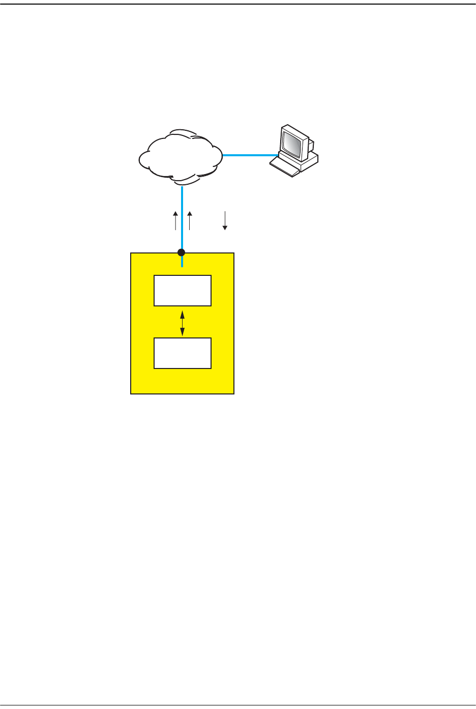
SNMP Overview
FlexWave Prism Host, Remote and EMS 5.1 System Reference Page 277
ADCP-77-073 • Issue 2 • 11/2009 © 2009 ADC Telecommunications, Inc.
12.2 SNMP OVERVIEW
The FlexWave system SNMP interface, shown schematically in Figure 12-2, allows a
remote user using an SNMP manager to access the same database as accessed by the
standard EMS interface. The database accessed is an SNMP database called a
Management Information Base (MIB).
Figure 12-2. SNMP Interface
This section describes the FlexWave system SNMP interface, and provides procedures
for using the SNMP interface to “get” and “set” system parameters and receive alarms.
In SNMP terminology, the parameters in a MIB are called “objects” and alarms are
called “traps.”
IP
IP
Web
GET/SETTRAP
75356-05
Windows 2000 or Windows XP
computer running
Internet Explorer 6.0
and/or SNMP Manager
MIB
EMS
INTERNAL
Network port
URH Host Unit

SNMP Interface
Page 278 FlexWave Prism Host, Remote and EMS 5.1 System Reference
© 2009 ADC Telecommunications, Inc ADCP-77-073 • Issue 2 • 11/2009
12.2.1 Background Information on SNMP
SNMP (Simple Network Management Protocol) is an international standard for remote
control of online devices. A typical scenario involves the devices being controlled,
remote computers (called managers) that can control them, a network connection,
and SNMP software. The SNMP software includes SNMP manager software on each
controlling computer and SNMP “proxy agent” software and one or more MIBs on
each of the controlled devices.
A MIB is a database defined in accordance with SNMP requirements. A MIB consists
of tables of objects used to exchange information between a manager and agent.
Information is exchanged using three basic operations: GET, SET, and TRAP. A
manager uses GET to obtain an object value from a MIB and SET to set an object to a
new value. A TRAP is a notification that is sent out by an agent when the value of a
trap object exceeds a threshold defining an alarm state.
In a manager browser, a MIB looks like an Explorer hierarchy of folders and files, as
shown in Figure 12-3. The items at the lowest level, analogous to files in the Explorer
view, are not files, however; they are objects that each represent one system
parameter (object) and its current value. MIB objects are arranged in tables. Each set
of objects (within a single folder) represents one such table. An object marked with a
key symbol indicates that view is the key value for that table.
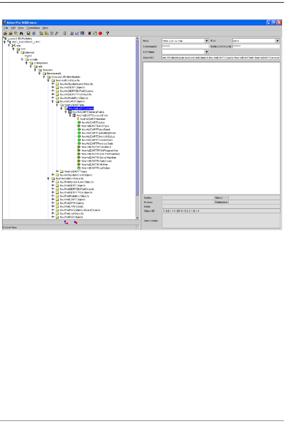
SNMP Overview
FlexWave Prism Host, Remote and EMS 5.1 System Reference Page 279
ADCP-77-073 • Issue 2 • 11/2009 © 2009 ADC Telecommunications, Inc.
Figure 12-3. MIB in MIB Browser
In the FlexWave system, the MIB accessed through the SNMP interface is the same
database as used by the EMS graphical user interface. There is therefore a one-to-one
correspondence between MIB objects and the parameters displayed in the EMS Web
pages. Likewise, there is a one-to-one correspondence between the SNMP trap objects
and the alarm indicator LEDs displayed on the EMS pages. The MIB object names and
the EMS page names for the same items differ in a way that can be easily figured out.
For example, the MIB object “fwuHstDARTPassBand” corresponds to the “Host DART
Pass Band” parameter on the Host DART Configuration and Alarm Details Page.

SNMP Interface
Page 280 FlexWave Prism Host, Remote and EMS 5.1 System Reference
© 2009 ADC Telecommunications, Inc ADCP-77-073 • Issue 2 • 11/2009
12.2.2 MIB Used by FlexWave System
The FlexWave system uses a single MIB called the ADC-FLEXWAVE-URH.mib. The MIB
resides on the SeRF card in the Host where the EMS software also runs. The SNMP
proxy agent software required for the interface with SNMP managers also resides and
runs on the Host SeRF card.
A complete list of the objects that compose the FlexWave-Prism Agent MIB are listed
in this section in two tables. Table 12-2 on Page 292 lists objects that may be accessed
for GET/SET operation. Table 12-3 on page 308 lists traps that are sent to SNMP
managers registered to receive them whenever the respective fault condition occurs.
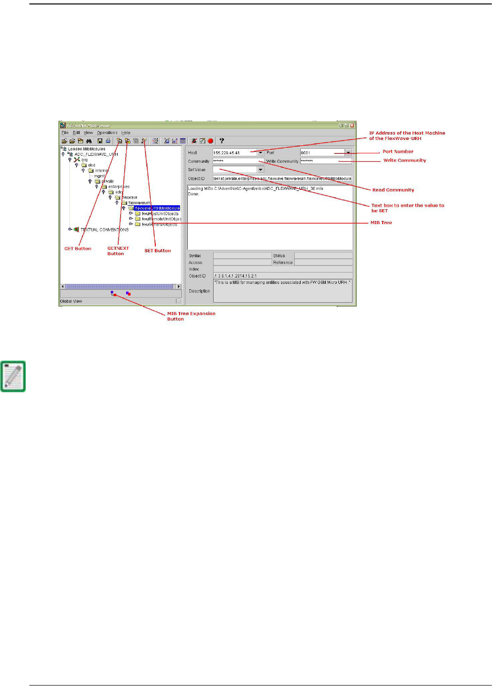
SNMP Procedures
FlexWave Prism Host, Remote and EMS 5.1 System Reference Page 281
ADCP-77-073 • Issue 2 • 11/2009 © 2009 ADC Telecommunications, Inc.
12.3 SNMP PROCEDURES
This topic contains procedures done at the SNMP manager to interact with the
FlexWave-Prism Agent MIB. Any SNMP manager may be used. These procedures are
illustrated with examples from an AdventNet MIB Browser.
Figure 12-4 shows the features of a typical MIB browser.
Figure 12-4. Typical MIB Browser
Examples shown in this chapter use the AdventNet MIB Browser. Some procedural
details may vary with another browser, but the basic steps are the same.
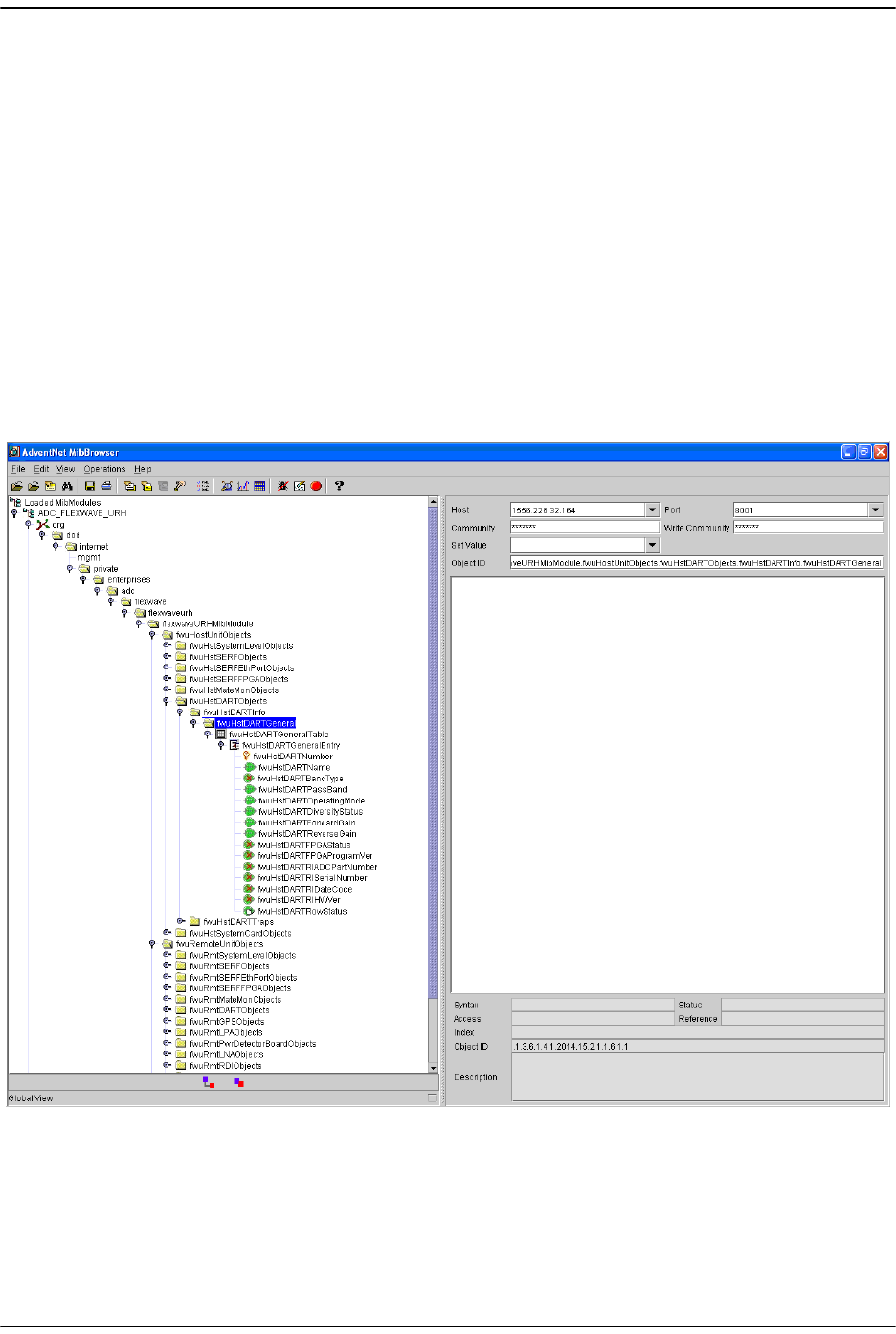
SNMP Interface
Page 282 FlexWave Prism Host, Remote and EMS 5.1 System Reference
© 2009 ADC Telecommunications, Inc ADCP-77-073 • Issue 2 • 11/2009
12.4 ACCESSING THE FLEXWAVE-PRISM AGENT MIB
The FlexWave-Prism Agent MIB can be accessed using any SNMP manager with an
active network connection. The IP address of the FlexWave-Prism Host must be
known and entered in the MIB browser.
11 On the manager computer, open the MIB Browser.
22 Load the ADC-FLEXWAVE-URH.mib file.
33 Enter the IP address of the Host of the FlexWave-Prism system in the text box
provided next to
Host
.
44 Enter the
Port number
as 8001.
55 Enter the Read Community as public and Write Community as private.
66 To see an overview the MIB content, expand the MIB tree.

Configuring the Trap Viewer
FlexWave Prism Host, Remote and EMS 5.1 System Reference Page 283
ADCP-77-073 • Issue 2 • 11/2009 © 2009 ADC Telecommunications, Inc.
12.5 CONFIGURING THE TRAP VIEWER
Configuring a trap viewer enables it to receive traps from the FlexWave system.
12.5.1 Registering the Manager for Receiving Traps
(static—non AdventNet MIB Browser)
To receive traps, the manager must first be registered with the FlexWave-Prism Agent
using the following procedure.
11 Open a telnet or ssh connection to the Host.
22 Stop the agent process with the following command: service URHagent stop
33Edit /usr/local/fwu/conf/snmp/v2managertable.txt and add a line for each
trap receiver that looks like this:
155.226.32.101 8003 SNMP_VERSION_2c public 30 5 ACTIVE
44 Start the agent process with the following command: service URHagent start
This procedure cannot be done with the AdventNet MIB Browser.
The balance of the line should be the same for all trap managers, except:
••Replace “155.226.32.101” in the example with the IP address of the computer being
used by the trap manager.
• 8003 is the destination port used. The Default SNMP trap port is 162. Any port
number is supported.
You can't use both a static and dynamic trap agent configuration. You can only use one
or the other. If you configure static, the dynamic entries will be deleted.
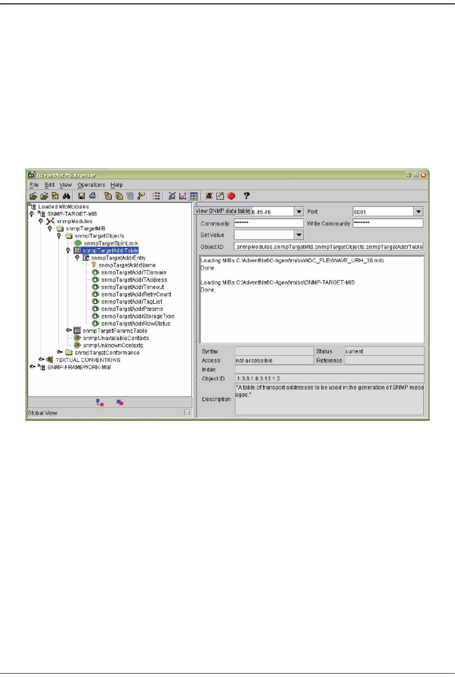
SNMP Interface
Page 284 FlexWave Prism Host, Remote and EMS 5.1 System Reference
© 2009 ADC Telecommunications, Inc ADCP-77-073 • Issue 2 • 11/2009
12.5.2 Registering the Manager for Receiving Traps
(dynamic—AdventNet MIB Browser)
To receive traps, the manager must first be registered with the FlexWave-Prism Agent
using the following procedure.
11 Open the MIB-browser and load the
SNMP-TARGET-MIB
.
22 Expand the MIB tree.
33 Set the common parameters such as
Host
,
Port and Community
, and
Write
Community
.
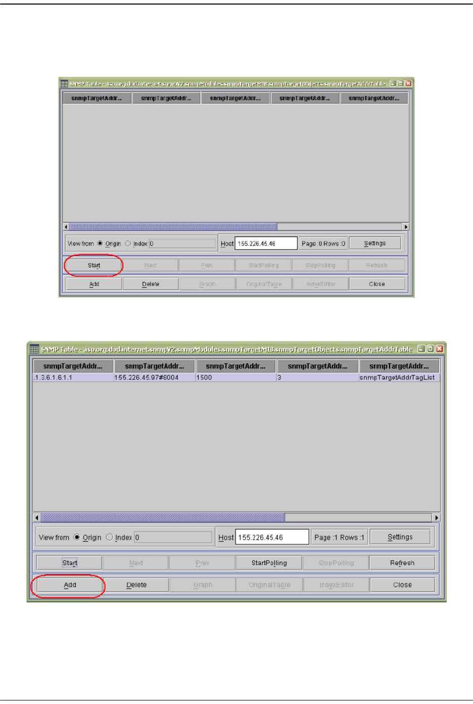
Configuring the Trap Viewer
FlexWave Prism Host, Remote and EMS 5.1 System Reference Page 285
ADCP-77-073 • Issue 2 • 11/2009 © 2009 ADC Telecommunications, Inc.
44 Select the
snmpTargetAddrTable
and then click on the
View SNMP Data Table
icon or
View -> SNMP Table
.
55 In the window that opens, click
Start
.
66 In the window that opens, click
Add
to add the manager information.
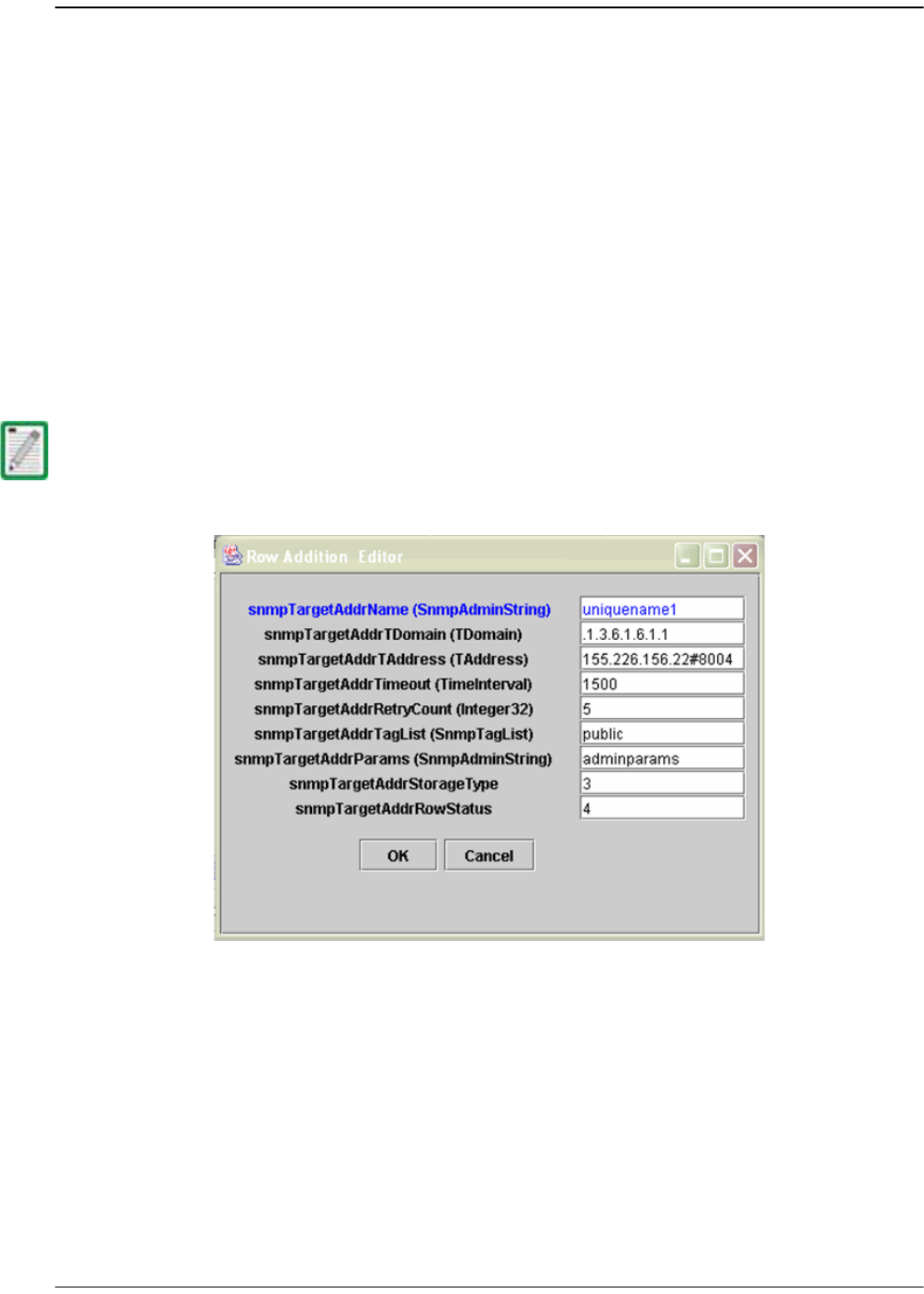
SNMP Interface
Page 286 FlexWave Prism Host, Remote and EMS 5.1 System Reference
© 2009 ADC Telecommunications, Inc ADCP-77-073 • Issue 2 • 11/2009
77 Set the manager information as follows:
•
snmpTargetAddrName
—any unique name
•
snmpTargetAddrDomain
—.1.3.6.1.6.1.1
•
snmpTargetAddrTAddress
—IP address of the machine where you want to receive
the traps, The port number should also be provided next to IP address (for
example, #8004)
•
snmpTargetAddrTimeout
—timeout value
•
snmpTargetAddrRetryCount
—retry count
•
snmpTargetAddrTagList
—any string that will be used as a community string to
view the traps; the default community string is
public
•
snmpTargetAddrParams
—any string, usually
group1
•
snmpTargetAddrStorageType
—3
88 Click
OK
.
The information given in Step 7 displays as a new row in the SNMP Table.
99 Click
Close
to close the SNMP Table.
You can't use both a static and dynamic trap agent configuration. You can only use one
or the other. If you configure dynamic, the static entries will be deleted.

Configuring the Trap Viewer
FlexWave Prism Host, Remote and EMS 5.1 System Reference Page 287
ADCP-77-073 • Issue 2 • 11/2009 © 2009 ADC Telecommunications, Inc.
12.5.3 Viewing Traps
This section describes how to view traps in the MIB Browser and how to interpret
responses.
12.5.3.1 Date and Time Stamps
The FlexWave MIB imports the date and time in the format of:
EEE, MMM dd, HH:mm:ss
Table 12-1 describes the date and time fields.
For example, Tuesday February 26 at 1:30:15 PM would be displayed as:
TUE, FEB 26, 13:30:15
Table 12-1. MIB Date and Time Stamp Fields
Field Contents Variable
EEE Three letter abbreviation for the day of the week SUN - SAT
MMM Three letter month abbreviation JAN - DEC
dd Two-digit day of the month 01-31
HH Two-digit hour for a 24-hour clock; AM/PM will not
display
00 - 23
mm Two-digit minute 00 through 59
ss Two-digit second 00 through 59

SNMP Interface
Page 288 FlexWave Prism Host, Remote and EMS 5.1 System Reference
© 2009 ADC Telecommunications, Inc ADCP-77-073 • Issue 2 • 11/2009
12.5.3.2 Variable Bindings
For Host Traps, there are 9 variable bindings:
11 sysUpTime
22 snmpTrapOID
33 fwuTrapSequenceNumber
44 fwuTrapTimeStamp
55 fwuModuleNumber
66 fwuModuleType
77 fwuHstNumber
88 fwuHstName
99 fwuNotificationStatus
For Remote Traps, there are 11 variable bindings:
11 sysUpTime
22 snmpTrapOID
33 fwuTrapSequenceNumber
44 fwuTrapTimeStamp
55 fwuModuleNumber
66 fwuModuleType
77 fwuHstNumber
88 fwuHstName
99 fwuRmtNumber
100fwuRmtName
111 fwuNotificationStatus
You can therefore determine the affected module based on the module number and
type (variable binding 5 and 6).

Configuring the Trap Viewer
FlexWave Prism Host, Remote and EMS 5.1 System Reference Page 289
ADCP-77-073 • Issue 2 • 11/2009 © 2009 ADC Telecommunications, Inc.
The module types are represented numerically as follows:
11 Host
22 Remote
33 SeRF
44DART
55 SFP
66 RSI
77 RDI
88 Power Detector
99 LPA
100 LNA
111 Duplexer
122 GPS
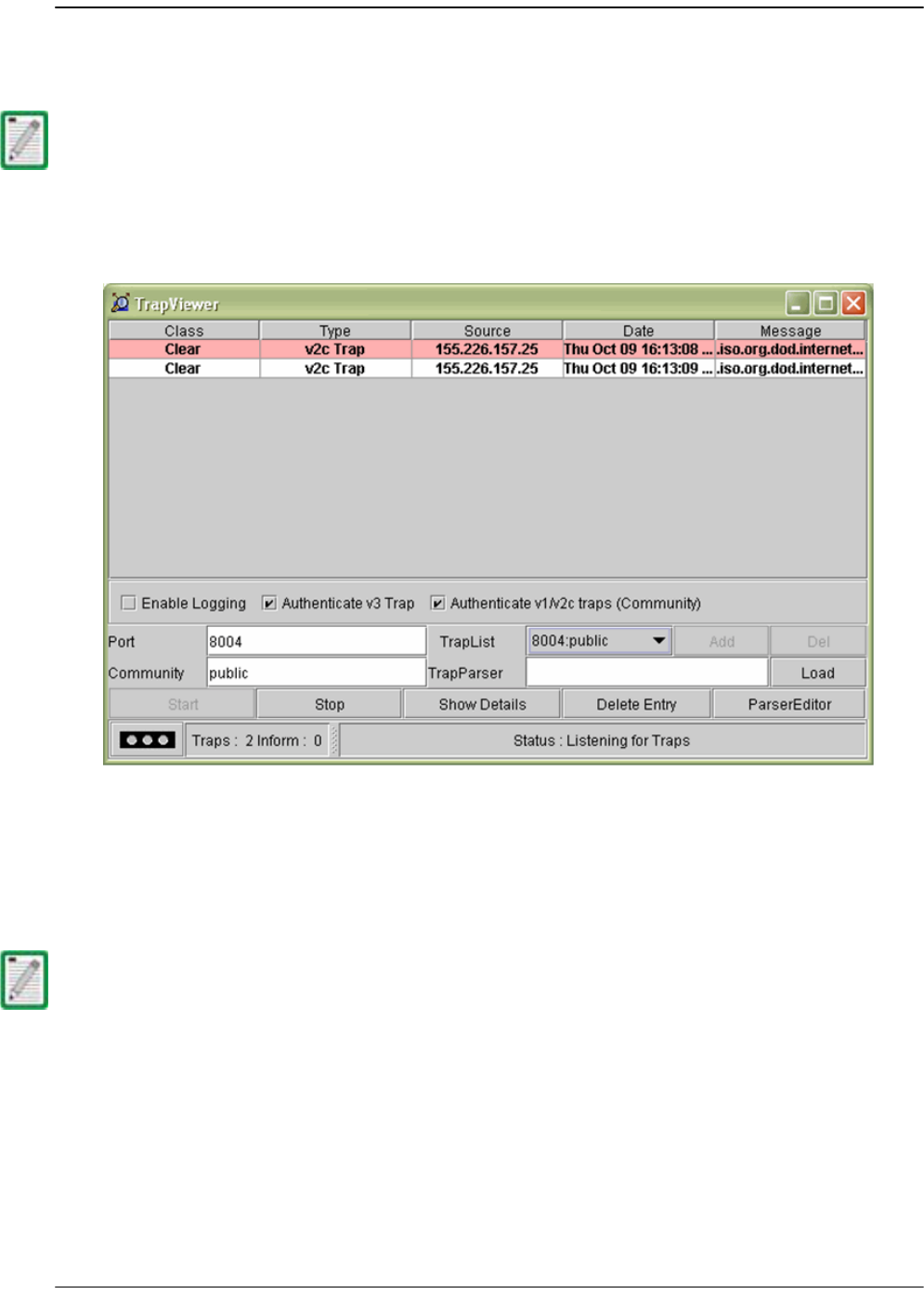
SNMP Interface
Page 290 FlexWave Prism Host, Remote and EMS 5.1 System Reference
© 2009 ADC Telecommunications, Inc ADCP-77-073 • Issue 2 • 11/2009
12.5.3.3 View the Traps
11 In the AdventNet MIB Browser, click the
Trap Viewer
icon on the Toolbar.
The
Trap Viewer
dialog opens.
22 In the
Port
box, enter the desired port number. The default is
162
.
33 (Optional) In the
Community
box, enter the community string for the incoming
traps. The default is
public
.
44 Click the
Add
button to add the
Port
and
Community
list to the
Trap
list (visible in
the
TrapList
list box).
55 Click the
Load
button to load the trap parser file.
66 Click the
Start
button. Trap Viewer begins to receive traps from the specified port
and community.
To receive traps using the manager, you must first register the manager using the
procedure in “Registering the Manager for Receiving Traps (static—non AdventNet MIB
Browser)” on page 283 or in “Registering the Manager for Receiving Traps
(dynamic—AdventNet MIB Browser)” on page 284.
The Port and Community list can be deleted by clicking the Delete Entry button.
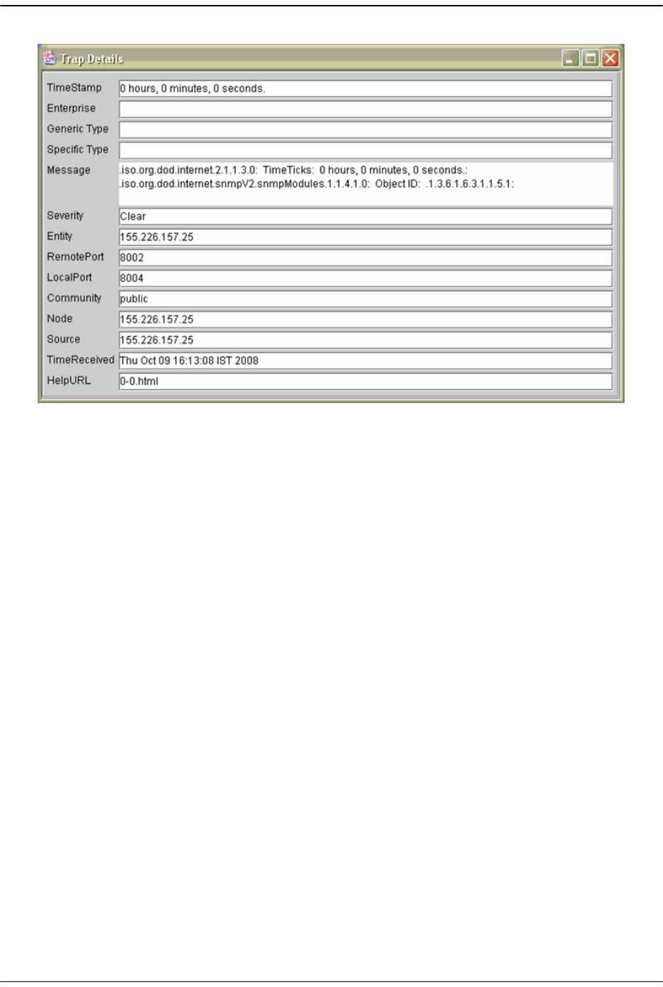
Configuring the Trap Viewer
FlexWave Prism Host, Remote and EMS 5.1 System Reference Page 291
ADCP-77-073 • Issue 2 • 11/2009 © 2009 ADC Telecommunications, Inc.
The traps when received are listed in the
Trap Table
. The trap table has the
following five columns.
•
Class
—defines the severity of the trap.
•
Type
—defines the type of the trap or the inform request.
•
Source
—represents the IP address of the source from where the traps were
sent.
•
Date
—shows the date and time when the trap was received.
•
Message
—lists the VarBind list of the trap, if any.
The status of the trap is displayed in the status pane at the bottom of the dialog
box. Moreover, the Trap count and the inform count is displayed in the status
pane.
77 To log the received traps, select the
Enable Logging
check box. All the incoming
traps are logged to a file. The default name of the log file is
trap.log
.
88 To view the details of the traps, click on the
Show Details
button. You can also
right-click the trap in the trap table and select
View Trap Details
.
99 Click
Stop
to stop listening to the port.
100 To delete a trap, select the trap and click the
Delete Entry
button. You can also
right-click the trap in the trap table and select
Delete the Selected Rows
.
Another option in
Trap Viewer
is the
ParserEditor
.
Trap Viewer
can filter the incoming
traps according to certain criterion called the Parser Criteria. The configuration of
the criterion is made possible by using the
ParserEditor
.

SNMP Interface
Page 292 FlexWave Prism Host, Remote and EMS 5.1 System Reference
© 2009 ADC Telecommunications, Inc ADCP-77-073 • Issue 2 • 11/2009
12.6 FLEXWAVE-URH AGENT MIB
Objects in the FlexWave-URH Agent MIB divide into two types:
GET
/
SET
objects and
trap objects. This section describes the
GET
/
SET
objects. For information on trap
objects, see “Traps” on page 308.
Table 12-2 lists all objects within the FlexWave-URH Agent MIB that are available for
GET and/or SET commands. Objects that are available for SET commands are also
available for GET commands.
For each SNMP syntax, there is a range of values defined in the MIB file. These are the
possible values that can be entered in a SET command and returned in a GET
command.
You can also
Enable
or
Disable
masking, which sets whether the trap will be raised
(
Disable
) or not (
Enable
). Thresholds dictate when a trap will be activated. Table 12-2
lists all FlexWave-URH Agent MIB objects for which traps, masks and thresholds are
sent to the SNMP manager.
Table 12-2. FlexWave-URH Agent MIB GET/SET Objects
Object Name Description SNMP Syntax Get
or
SET
fwuTrapSequenceNumber
Total number of traps raised
by the agent.
Counter32 GET
fwuTrapTimeStamp
Time stamp when trap was
raised.
DateAndTime GET
fwuHstOverTempFaultMask
Show masking status of Over
Temperature fault. Masking
is disabled by default. If
enabled, the trap will not be
raised.
MASKType SET
fwuHstUnderTempFaultMask
Show status of masking of
Under Temperature fault.
Masking is disabled by
default. If enabled, the trap
will not be raised.
MASKType SET
fwuHstSERFFPGAStatus
Host SeRF Card FPGA status
where 0 indicates that the
SeRF can talk to the FPGA and
1 indicates that it cannot
INTEGER GET
fwuHstSysCardRIADCPartNumber
Remote Inventory Data-ADC
Part Number
DisplayString GET
fwuHstSysCardRISerialNumber
Remote Inventory Data-Serial
Number
DisplayString GET
fwuHstSysCardRIDateCode
Remote Inventory Data-Date
Code
DisplayString GET
fwuHstSysCardRIHWVer
Remote Inventory
Data-Hardware Version
DisplayString GET

FlexWave-URH Agent MIB
FlexWave Prism Host, Remote and EMS 5.1 System Reference Page 293
ADCP-77-073 • Issue 2 • 11/2009 © 2009 ADC Telecommunications, Inc.
fwuHstSysCard10MhzRefClock
System Card Reference clock,
which can be can be internal
(0) or external (1)
INTEGER SET
fwuHstSysCardCPLevel
System Card Master Clock
Priority Level, which can be
from 0 to 15
Integer SET
fwuHstSysCardFanFaultMask
Host System Card Fan Fault
Mask. The alarm is disabled
by default. Enable the alarm
by setting it to enabled (1).
MASKType SET
fwuHstSysCardPrimaryCPFaultMask
Primary Clock Priority Fault
Mask. The alarm is disabled
by default. Enable the alarm
by setting it to enabled (1).
MASKType SET
fwuHstSysCardSecondaryCPFaultMask
Secondary Clock Priority Fault
Mask. The alarm is disabled
by default. Enable the alarm
by setting it to enabled (1).
MASKType SET
fwuHstOverTempThreshold
Host System Card Over
Temperature threshold value.
This is not user settable.
Integer32 SET
fwuHstUnderTempThreshold
Host System Card Under
Temperature Threshold
value. This is not user
settable.
Integer32 SET
fwuRmtSERFFPGAStatus
Remote SeRF Card FPGA
status where 0 indicates that
the SeRF can talk to the FPGA
and 1 indicates that it cannot
INTEGER GET
fwuRmtRSIRIADCPartNumber
Remote Inventory Data-ADC
Part Number
DisplayString GET
fwuRmtRSIRISerialNumber
Remote Inventory Data-Serial
Number
DisplayString GET
fwuRmtRSIRIDateCode
Remote Inventory Data-Date
Code
DisplayString GET
fwuRmtRSIRIHWVer
Remote Inventory
Data-Hardware Version
DisplayString GET
fwuRmtCapacity
The number of RF Modules
that can be installed in the
Remote (1 - 4)
Unsigned32 GET
fwuHstNumber
FlexWave URH Host Number HOSTNBRType GET
fwuHstName
User assigned name of the
Host. It can be 40 characters
long
DisplayString SET
Table 12-2. FlexWave-URH Agent MIB GET/SET Objects (Cont.)
Object Name Description SNMP Syntax Get
or
SET

SNMP Interface
Page 294 FlexWave Prism Host, Remote and EMS 5.1 System Reference
© 2009 ADC Telecommunications, Inc ADCP-77-073 • Issue 2 • 11/2009
fwuHstUnitReset
Host SeRF card can be reset
by setting a value of 1
INTEGER SET
fwuHstBackPlaneRev
Revision of Host back plane. DisplayString GET
fwuHstAlarmStatusSummary
Host Alarm Status Summary,
where the severity of the
alarm is:
•Normal = 1
•Minor = 2
•Major = 3
• Not Present = 0
ALARMType GET
fwuHstTempMeas
Host system temperature
value in Celsius
DisplayString GET
fwuSystemAlarmStatusSummary
System Alarm Status
Summary, where the severity
of the alarm is:
•Normal = 1
•Minor = 2
•Major = 3
• Not Present = 0
ALARMType GET
fwuHstLinkingMode
System Linking mode for
DART linking
Integer SET
fwuHstMajorContactAlarmOutput
Host Major contact output
port state
CONTACTTyp
e
GET
fwuHstMinorContactAlarmOutput
Host Minor contact output
port state
CONTACTTyp
e
GET
fwuRmtMajorContactAlarmOutput
Remote Major contact output
port state
CONTACTTyp
e
GET
fwuRmtMinorContactAlarmOutput
Remote Minor contact output
port state
CONTACTTyp
e
GET
fwuSystemAlarmSequenceNumber
Defines the index of the
Alarm Table
Unsigned32 GET
fwuSystemAlarmAgentUpTime
Agent up time TimeTicks GET
fwuSystemAlarmType
Trap OID of the Alarm OBJECT
IDENTIFIER
GET
fwuSystemAlarmHstNumber
Host number from which the
alarm has been raised
HOSTNBRType GET
fwuSystemAlarmHstName
Name of the Host from which
the alarm has been raised
DisplayString GET
fwuSystemAlarmRmtNumber
Remote number from which
the alarm has been raised
REMOTENBRT
ype
GET
Table 12-2. FlexWave-URH Agent MIB GET/SET Objects (Cont.)
Object Name Description SNMP Syntax Get
or
SET

FlexWave-URH Agent MIB
FlexWave Prism Host, Remote and EMS 5.1 System Reference Page 295
ADCP-77-073 • Issue 2 • 11/2009 © 2009 ADC Telecommunications, Inc.
fwuSystemAlarmRmtName
Remote name from which the
alarm has been raised
DisplayString GET
fwuSystemAlarmModuleType
Type of module raising the
alarm
MODULEType GET
fwuSystemAlarmModuleNumber
Identifier of the module
raising the alarm.
Integer32 GET
fwuSystemAlarmSeverity
This object gives the severity
of this Alarm notification.
•Normal = 1
•Minor = 2
•Major = 3
• Not Present = 0
ALARMType GET
fwuSystemAlarmTimeStamp
Time stamp of the Alarm DateAndTime GET
fwuHstSERFLinuxKernelVer
Linux Kernel Version of the
Host system
DisplayString GET
fwuHstSERFLinuxBootLoaderVer
Boot Loader Version of the
Host system
DisplayString GET
fwuHstSERFCompactFlashSWVer
Compact Flash Version of the
Host system
DisplayString GET
fwuHstSERFFPGAVer
Version of FPGA image
loaded on SeRF
DisplayString GET
fwuHstSERFPPCSNMPHTTPAgentSWVer
Software Version of the
HTTP/SNMP agent running on
Host
DisplayString GET
fwuHstSERFPPCHWMonSWVer
Software Version of the
Hardware Monitor process
running on the Host
DisplayString GET
fwuHstSERFPPCAPPMonSWVer
Software Version of the
Application Monitor process
running on the Host
DisplayString GET
fwuHstSERFPPCMATEMonSWVer
Software Version of the Mate
Monitor process running on
the Host
DisplayString GET
fwuHstSERFPPCENETMonSWVer
Software Version of the
Ethernet Monitor process
running on the Host
DisplayString GET
fwuHstSERFPPCFPGAMonSWVer
Software Version of the FPGA
Monitor process running on
the Host
DisplayString GET
fwuHstSERFRIDateCode
Host SeRF Inventory-Date
Code
DisplayString GET
Table 12-2. FlexWave-URH Agent MIB GET/SET Objects (Cont.)
Object Name Description SNMP Syntax Get
or
SET

SNMP Interface
Page 296 FlexWave Prism Host, Remote and EMS 5.1 System Reference
© 2009 ADC Telecommunications, Inc ADCP-77-073 • Issue 2 • 11/2009
fwuHstSERFRIHWVer
Host SeRF
Inventory-Hardware Version
DisplayString GET
fwuHstSERFRISerialNumber
Host SeRF Inventory-Serial
Number
DisplayString GET
fwuHstSERFRIADCPartNumber
Host SeRF Inventory-ADC Part
Number
DisplayString GET
fwuHstSERFOptSFPNumber
SFP Number-Optical Port
number (from 1 to 8)
INTEGER GET
fwuHstSERFOptSFPName
User defined name of the SFP
Optical Port that can be up to
32 characters long
DisplayString SET
fwuHstSERFOptSFPType
SFP Type-Optical Port Type OPTICSType GET
fwuHstSERFOptSFPTxColor
SFP wavelength in nanometer Integer32 GET
fwuHstSERFOptRevLaunchPowerMeas
Value of Host Receive
measured optical power in
dBm
DisplayString GET
fwuHstSERFOptFwdLaunchPowerMeas
Value of Host Transmit
measured optical power in
dBm
DisplayString GET
fwuHstSERFOptMateName
Name of Host Mates DisplayString GET
fwuHstSERFIPEnable
IP Enable mode for Host
carrying RF, where 1 equals
enable
Integer SET
fwuHstSERFOptRxBERFaultThreshold
Threshold Value for declaring
a Decoded word error state of
the primary wavelength
optical receiver (too many
errors)
DisplayString SET
fwuHstSERFOptOverDriveFaultThreshld
Threshold value for declaring
SFP over drive fault. This is
not user settable.
Integer32 SET
fwuHstSERFOptUnderDriveFaultThreshld
Threshold value for declaring
SFP under drive fault. This is
not user settable.
Integer32 SET
fwuHstSERFOptRxBERFaultMask
Shows the masking status of
primary wavelength optical
receiver; masking is disabled
by default; if enabled, the trap
will not be raised.
MASKType SET
fwuHstSERFOptOverDriveFaultMask
Shows the masking status of
SFP Over Drive Fault; masking
is disabled by default; if
enabled, the trap will not be
raised.
MASKType SET
Table 12-2. FlexWave-URH Agent MIB GET/SET Objects (Cont.)
Object Name Description SNMP Syntax Get
or
SET

FlexWave-URH Agent MIB
FlexWave Prism Host, Remote and EMS 5.1 System Reference Page 297
ADCP-77-073 • Issue 2 • 11/2009 © 2009 ADC Telecommunications, Inc.
fwuHstSERFOptUnderDriveFaultMask
Shows the masking status of
Under Drive Fault. Masked is
disabled by default. If
enabled, the trap will not be
raised.
MASKType SET
fwuHstSERFOptIpEnableFaultMask
Shows the masking status of
the IP Enable Fault. Masked is
disabled by default. If
enabled, the trap will not be
raised.
MASKType SET
fwuHstSERFEthPortNumber
A unique identifier for each
Ethernet port (from 1 to 12)
Unsigned32 GET
fwuHstSERFEthPortType
Identifies the type of Ethernet
port
ENETType GET
fwuHstSERFEthPortRxBytes
Receive byte counter Counter64 GET
fwuHstSERFEthPortRxPkts
Receive packet counter Counter64 GET
fwuHstSERFEthPortRxFcsErrors
Receive FCS error counter Counter64 GET
fwuHstSERFEthPortRxBroadcastPkts
Receive Broadcast packet
counter
Counter64 GET
fwuHstSERFEthPortRxMulticastPkts
Receive Multicast packet
counter
Counter64 GET
fwuHstSERFEthPortRxFragmtdFrames
Receive fragments counter Counter64 GET
fwuHstSERFEthPortRxJabbersFrames
Receive jabber counter Counter64 GET
fwuHstSERFEthPortTxByteCounter
Transmit byte counter Counter64 GET
fwuHstSERFEthPortTxPkts
Transmit packet counter Counter64 GET
fwuHstSERFEthPortTxBroadcastPkts
Transmit broadcast packet
counter
Counter64 GET
fwuHstSERFEthPortTxMulticastPkts
Transmit multicast packet
counter
Counter64 GET
fwuHstSERFEthPortSFPId
Identifier of SFP to which this
Ethernet port connects
Unsigned32 GET
fwuHstDARTNumber
A unique identifier for each
DART Card Object (from 1 to
8)
Integer32 GET
fwuHstDARTName
A user defined name for each
DART Card object that can be
up to 32 characters long
DisplayString SET
fwuHstDARTBandType
Band type of Host DART card BANDType GET
fwuHstDARTPassBand
Pass-band type of host DART
card.
PASSBANDTyp
e
SET
Table 12-2. FlexWave-URH Agent MIB GET/SET Objects (Cont.)
Object Name Description SNMP Syntax Get
or
SET

SNMP Interface
Page 298 FlexWave Prism Host, Remote and EMS 5.1 System Reference
© 2009 ADC Telecommunications, Inc ADCP-77-073 • Issue 2 • 11/2009
fwuHstDARTOperatingMode
Operating mode of Host
DART card
MODEType SET
fwuHstDARTDiversityStatus
Diversity Status of Host DART
card, where diversity is 1 and
no diversity is 0
INTEGER SET
fwuHstDARTForwardGain
Primary Gain in forward path
of Host DART card
GAINType SET
fwuHstDARTReverseGain
Primary Gain in reverse path
of Host DART card
GAINType SET
fwuHstDARTFPGAStatus
Indicates if the Host SeRF
FPGA can talk to the DART
FPGA where 0 indicates that
the SeRF can talk to the FPGA
and 1 indicates that it cannot
INTEGER GET
fwuHstDARTFPGAProgramVer
FPGA Version on the Host
DART card
DisplayString GET
fwuHstDARTRIADCPartNumber
Host DART Inventory
Data-ADC Part Number
DisplayString GET
fwuHstDARTRISerialNumber
Host DART Inventory
Data-Serial Number
DisplayString GET
fwuHstDARTRIDateCode
Host DART Inventory Data -
Date Code
DisplayString GET
fwuHstDARTRIHWVer
Host DART Inventory
Data-Hardware Version
DisplayString GET
fwuHstDARTRowStatus
Status of this conceptual row RowStatus SET
fwuHstDARTOverDriveFaultThreshold
Threshold value for Host
DART Card Over Drive. This is
not user settable.
DisplayString SET
fwuHstDARTUnderDriveFaultThreshold
Threshold value for Host
DART Card Under Drive. This
is not user settable.
DisplayString SET
fwuRmtNumber
The Remote number of
Remote connected (from 1 to
8)
INTEGER GET
fwuRmtCatalogState
Catalog state of Remote. If
fwuRmtCatalogState is
commission (2) state,
commission Remote. If it is in
normal (1) state, do not
commission Remote
CATALOGTyp
e
GET
fwuRmtName
User defined name of the
Remote, which can be up to
40 characters long
DisplayString SET
Table 12-2. FlexWave-URH Agent MIB GET/SET Objects (Cont.)
Object Name Description SNMP Syntax Get
or
SET

FlexWave-URH Agent MIB
FlexWave Prism Host, Remote and EMS 5.1 System Reference Page 299
ADCP-77-073 • Issue 2 • 11/2009 © 2009 ADC Telecommunications, Inc.
fwuRmtAlarmStatusSummary
Summary of alarm status of
all connected remote units
where:
•Normal = 1
•Minor = 2
•Major = 3
• Not Present = 0
ALARMType GET
fwuRmtTempMeasurement
Temperature of each Remote
in Celsius. This value comes
from the RSI
DisplayString GET
fwuRmtGeneralTableRowStatus
Status of this conceptual row RowStatus SET
fwuRmtType
Type of Remote: Prism or URH REMOTEType GET
fwuRmtSERFLinuxKernelVer
Linux Kernel Version of the
Remote system
DisplayString GET
fwuRmtSERFLinuxBootLoaderVer
Linux Boot loader Version of
the Remote system
DisplayString GET
fwuRmtSERFCompactFlashSWVer
Compact Flash Software
Version of the Remote system
DisplayString GET
fwuRmtSERFFPGAVer
Version of FPGA loaded on
SeRF
DisplayString GET
fwuRmtSERFPPCHWMonSWVer
Hardware monitor process
Software Version of the
Remote system
DisplayString GET
fwuRmtSERFPPCAPPMonSWVer
Application monitor process
Software Version of the
Remote system
DisplayString GET
fwuRmtSERFPPCGPSMonSWVer
GPS monitor process
Software Version of the
Remote system
DisplayString GET
fwuRmtSERFPPCSNMPHTTPAgentSWVer
SNMP agent Software Version
of the Remote system
DisplayString GET
fwuRmtSERFPPCMATEMonSWVer
Mate monitor process
Software Version of the
remote system.
DisplayString GET
fwuRmtSERFPPCENETMonSWVer
ENET monitor process
Software Version of the
Remote system
DisplayString GET
fwuRmtSERFPPCFPGAMonSWVer
FPGA monitor process
Software Version of the
Remote system
DisplayString GET
fwuRmtSERFRIDateCode
Remote SeRF Inventory-Date
Code of the Remote system
DisplayString GET
Table 12-2. FlexWave-URH Agent MIB GET/SET Objects (Cont.)
Object Name Description SNMP Syntax Get
or
SET

SNMP Interface
Page 300 FlexWave Prism Host, Remote and EMS 5.1 System Reference
© 2009 ADC Telecommunications, Inc ADCP-77-073 • Issue 2 • 11/2009
fwuRmtSERFRIHWRev
Remote SeRF Inventory -
Hardware Version of the
Remote system
DisplayString GET
fwuRmtSERFRISerialNumber
Remote SeRF Inventory-Serial
Number
DisplayString GET
fwuRmtSERFRIADCPartNumber
Remote SeRF Inventory-ADC
Part Number
DisplayString GET
fwuRmtSERFOptSFPNumber
A unique identifier of each
SFP (from 1 to 8)
INTEGER GET
fwuRmtSERFOptSFPName
User defined name of each
Remote SFP.It can be 32
character long.
DisplayString SET
fwuRmtSERFOptSFPType
SFP Type-Optical Port Type OPTICSType GET
fwuRmtSERFOptSFPColor
SFP wavelength in nanometer. Integer32 GET
fwuRmtSERFOptRevLaunchPowerMeas
Value of Remote Receive
measured optical power in
dbm
DisplayString GET
fwuRmtSERFOptFwdLaunchPowerMeas
Value of Remote Transmit
measured optical power in
dbm
DisplayString GET
fwuRmtSERFOptMateName
Name of Remote mate DisplayString GET
fwuRmtSERFIPEnable
IP Enable mode for Host
connected to the Remote that
is carrying RF, where 1 equals
enable
Integer GET
fwuRmtSERFOptRxBERFaultThreshold
Threshold Value for declaring
a Decoded word error state of
the primary wavelength
optical receiver (too many
errors). This is not user
settable.
DisplayString SET
fwuRmtSerfOptOverDriveFaultThreshld
Threshold value for declaring
SFP over drive fault. This is
not user settable.
Integer32 SET
fwuRmtSerfOptUnderDriveFaultThreshld
Threshold value for declaring
SFP under drive fault. This is
not user settable.
Integer32 SET
fwuRmtSERFOptRxBERFaultMask
Trap enable/disable for
primary wavelength optical
receiver; trap is enabled by
default; if disabled, the trap
will not be raised
MASKType SET
Table 12-2. FlexWave-URH Agent MIB GET/SET Objects (Cont.)
Object Name Description SNMP Syntax Get
or
SET

FlexWave-URH Agent MIB
FlexWave Prism Host, Remote and EMS 5.1 System Reference Page 301
ADCP-77-073 • Issue 2 • 11/2009 © 2009 ADC Telecommunications, Inc.
fwuRmtSERFOptOverDriveFaultMask
Trap enable/disable for SFP
Over Drive Fault. Trap is
enabled by default. If
disabled, the trap will not be
raised.
MASKType SET
fwuRmtSERFOptUnderDriveFaultMask
Trap enable/disable for SFP
Under Drive Fault; trap is
enabled by default; if
disabled, the trap will not be
raised
MASKType SET
fwuRmtSERFEthPortNumber
A unique identifier for each
Ethernet port (from 1 to 12)
Unsigned32 GET
fwuRmtSERFEthPortType
An identifier for the type of
Ethernet port
ENETType GET
fwuRmtSERFEthPortRxBytes
Receive byte counter Counter64 GET
fwuRmtSERFEthPortRxPkts
Receive packet counter Counter64 GET
fwuRmtSERFEthPortRxFscErrors
Receive FCS error counter Counter64 GET
fwuRmtSERFEthPortRxBroadcastPkts
Receive broadcast packet
counter
Counter64 GET
fwuRmtSERFEthPortRxMulticastPkts
Receive multicast packet
counter
Counter64 GET
fwuRmtSERFEthPortRxFragmtdFrames
Receive fragments counter Counter64 GET
fwuRmtSERFEthPortRxJabbersFrames
Receive jabber counter Counter64 GET
fwuRmtSERFEthPortTxByteCounter
Transmit byte counter Counter64 GET
fwuRmtSERFEthPortTxPkts
Transmit packet counter Counter64 GET
fwuRmtSERFEthPortTxBroadcastPkts
Transmit multicast packet
counter
Counter64 GET
fwuRmtSERFEthPortTxMulticastPkts
Transmit broadcast packet
counter
Counter64 GET
fwuRmtSERFEthSFPID
Identifier of SFP to which this
Ethernet port connects to
Unsigned32 GET
fwuRmtDARTNumber
A unique identifier for each
DART Card Object of Remote
(from 1 to 8)
Integer32 GET
fwuRmtDARTName
A user defined name for each
DART Card object of Remote,
which can be up to 32
characters
DisplayString SET
fwuRmtDARTBandType
Band type of Remote DART
card
BANDType GET
Table 12-2. FlexWave-URH Agent MIB GET/SET Objects (Cont.)
Object Name Description SNMP Syntax Get
or
SET

SNMP Interface
Page 302 FlexWave Prism Host, Remote and EMS 5.1 System Reference
© 2009 ADC Telecommunications, Inc ADCP-77-073 • Issue 2 • 11/2009
fwuRmtDARTPassBand
Pass-band type of remote
DART card.
PASSBANDTyp
e
SET
fwuRmtDARTOperatingMode
Operating mode of Remote
DART card
MODEType SET
fwuRmtDARTDiversityStatus
Diversity Status of Remote
DART card, where diversity is
1 and no diversity is 0
INTEGER SET
fwuRmtDARTForwardGain
Primary Gain in forward path
of Remote DART card
GAINType SET
fwuRmtDARTReverseGain
Primary Gain in reverse path
of Remote DART card
GAINType GET
fwuRmtDARTForwardDelay
Forward Delay for Remote
DART card Micro Seconds
(from 1 to 500). If the Forward
Delay value is not equal to
Actual Forward Delay value
then, then a Ranging fault will
be raised if the Remote DART
is Linked
DELAYType SET
fwuRmtDARTReverseDelay
Reverse Delay for Remote
DART card Micro Seconds
(from 1 to 500). If the Reverse
Delay value is not equal to the
Actual Reverse Delay value
then, then a Ranging fault will
be raised if the Remote DART
is linked
DELAYType SET
fwuRmtDARTTempMeas
Temperature value of Remote
DART card
DisplayString GET
fwuRmtDARTFPGAStatus
Indicates if the Remote SeRF
FPGA can talk to DART FPGA
where 0 indicates that the
SeRF can talk to the DART and
1 indicates that it cannot
INTEGER GET
fwuRmtDARTFPGAProgramVer
FPGA Version on the Remote
DART card
DisplayString GET
fwuRmtDARTRIADCPartNumber
Remote DART Inventory
Data-ADC Part Number
DisplayString GET
fwuRmtDARTRISerialNumber
Remote DART Inventory
Data-Serial Number
DisplayString GET
fwuRmtDARTRIDateCode
Remote DART Inventory Data
- Date Code
DisplayString GET
fwuRmtDARTRIHWVer
Remote DART Inventory
Data-Hardware Version
DisplayString GET
fwuRmtDARTGeneralTableRowStatus
Status of a row in the DART
General table
RowStatus SET
Table 12-2. FlexWave-URH Agent MIB GET/SET Objects (Cont.)
Object Name Description SNMP Syntax Get
or
SET

FlexWave-URH Agent MIB
FlexWave Prism Host, Remote and EMS 5.1 System Reference Page 303
ADCP-77-073 • Issue 2 • 11/2009 © 2009 ADC Telecommunications, Inc.
fwuRmtDARTActualForwardDelay
Forward Delay for Remote
DART
Integer32 GET
fwuRmtDARTForwardLowerboundDelay
Lower bound forward delay
value
Integer32 GET
fwuRmtDARTForwardUpperboundDelay
Upper bound delay value Integer32 GET
fwuRmtDARTActualReverseDelay
Reverse Delay for Remote
DART
Integer32 GET
fwuRmtDARTReverseLowerboundDelay
Lower bound Reverse delay
value
Integer32 GET
fwuRmtDARTReverseUpperboundDelay
Upper bound Reverse delay
value
Integer32 GET
fwuRmtDARTOverTempFaultMask
Masking status of DART over
Temp fault; masking is
disabled by default.If enabled
trap will not raised
MASKType SET
fwuRmtDARTUnderTempFaultMask
Masking status of DART
under Temp fault. Masking is
disabled by default.If enabled
trap will not raised
MASKType SET
fwuRmtDARTOverTempThreshold
Threshold value for remote
DART over temperature. This
is not user settable.
MASKType SET
fwuRmtDARTUnderTempThreshold
Threshold value for remote
DART under temperature.
This is not user settable.
MASKType SET
fwuRmtGPSLongitudeDegrees
The GPS Longitude in
Degrees (from -180 to 180)
INTEGER GET
fwuRmtGPSLongitudeMinutes
The GPS Longitude in Minutes
(from -59 to 59)
INTEGER GET
fwuRmtGPSLongitudeSeconds
The GPS Longitude in
milliseconds (from -5999 to
5999)
INTEGER GET
fwuRmtGPSLatitudeDegrees
The GPS Latitude in Degrees
(from -180 to 180)
INTEGER GET
fwuRmtGPSLatitudeMinutes
The GPS Latitude in Minutes
(from -59 to 59)
INTEGER GET
fwuRmtGPSLatitudeSeconds
The GPS Latitude in
milliseconds (from -5999 to
5999)
INTEGER GET
fwuRmtGPSAltitudeMeters
The GPS Altitude in Meters
(from -180 to 180)
INTEGER GET
fwuRmtGPSNumberOfSatellite
The Number of satellites
discovered (from -180 to 180)
INTEGER GET
Table 12-2. FlexWave-URH Agent MIB GET/SET Objects (Cont.)
Object Name Description SNMP Syntax Get
or
SET

SNMP Interface
Page 304 FlexWave Prism Host, Remote and EMS 5.1 System Reference
© 2009 ADC Telecommunications, Inc ADCP-77-073 • Issue 2 • 11/2009
fwuRmtGPSFaultMask
Shows masking status of GPS
Fault; masking is disabled by
default; if enabled, the trap
will not be raised
MASKType SET
fwuRmtLPANumber
A unique identifier for an LPA
(from 1 to 4)
Integer32 GET
fwuRmtLPAReset
Set this object to a value of 1
to cause LPA to reset itself.
Normal value is 0
INTEGER SET
fwuRmtLPAOpState
Operating mode of Remote
LPA, where normal is 0 and
standby is 1
INTEGER SET
fwuRmtPowerDetectorNumber
A unique identifier for each
power detector (from 1 to 4)
Integer32 GET
fwuRmtSystemVSWRMeas
VSWR (Voltage Standing Wave
Ratio) measurement
DisplayString GET
fwuRmtRFPowerOutputMeas
The value of Remote RF
Power Output in dBm
DisplayString GET
fwuRmtPwrDetectorBoardRIADCPartNum
Power Detector
Inventory-ADC Part Number
DisplayString GET
fwuRmtPwrDetectorBoardRISerialNum
Power Detector
Inventory-Serial Number
DisplayString GET
fwuRmtPwrDetectorBoardRIDateCode
Power Detector
Inventory-Date Code
DisplayString GET
fwuRmtPwrDetectorBoardRIHWVer
Power Detector
Inventory-Hardware Version
DisplayString GET
fwuRmtSystemVSWRFaultMask
System VSWR (Voltage
Standing Wave Ratio) Fault
MASKType SET
fwuRmtNoRFPowerFaultMask
No RF Power Fault MASKType SET
fwuRmtSystemVSWRFaultThreshold
Threshold value for System
VSWR (Voltage Standing Wave
Ratio) Fault. This is not user
settable.
Integer32 SET
fwuRmtLNANumber
A unique identifier for LNA
Objects (from 1 to 8)
Integer32 GET
fwuRmtLNAType
Remote LNA card type BANDType GET
fwuRmtLNARIADCPartNumber
LNA Inventory Data-ADC Part
Number
DisplayString GET
fwuRmtLNARISerialNumber
LNA Inventory Data-Serial
Number
DisplayString GET
fwuRmtLNARIDateCode
LNA Inventory Data-Date
Code
DisplayString GET
Table 12-2. FlexWave-URH Agent MIB GET/SET Objects (Cont.)
Object Name Description SNMP Syntax Get
or
SET

FlexWave-URH Agent MIB
FlexWave Prism Host, Remote and EMS 5.1 System Reference Page 305
ADCP-77-073 • Issue 2 • 11/2009 © 2009 ADC Telecommunications, Inc.
fwuRmtLNARIHWVer
LNA Inventory Data-Hardware
Version.
DisplayString GET
fwuRmtLNAPowerFaultMask
Shows masking status of
Remote LNA Power Fault;
masking is disabled by
default; if enabled, the trap
will not be raised
MASKType SET
fwuRmtRDINumber
A unique identifier for each
RDI (from 1 to 4)
Integer32 GET
fwuRmtRDIRIADCPartNumber
RDI Inventory Data-ADC Part
Number
DisplayString GET
fwuRmtRDIRISerialNumber
RDI Inventory Data-Serial
Number
DisplayString GET
fwuRmtRDIRIDateCode
RDI Inventory Data-Date Code DisplayString GET
fwuRmtRDIRIHWVer
RDI Inventory Data-Hardware
Version
DisplayString GET
fwuHstDARTOverDriveFaultMask
Shows masking status of
Host DART Over Drive Fault;
masking is disabled by
default; if enabled, the trap
will not be raised
MASKType SET
fwuHstDARTUnderDriveFaultMask
Shows masking status of
Host DART Under Drive Fault;
masking is disabled by
default; if enabled, the trap
will not be raised
MASKType SET
fwuRmtOverTempFaultMask
Show status of masking of
Remote over temperature
Fault; masking is disabled by
default; if enabled, the trap
will not be raised
MASKType SET
fwuRmtUnderTempFaultMask
Show status of masking of
Remote Under Temperature
Fault; masking is disabled by
default; if enabled, the trap
will not be raised
MASKType SET
fwuRmtOpenDoorFaultMask
Show status of masking of
Remote Open Door Fault;
masking is disabled by
default; if enabled, the trap
will not be raised
MASKType SET
fwuRmtFanOverSpeedFaultMask
Show status of masking of
Remote Fan Over Speed Fault;
masking is disabled by
default; if enabled, the trap
will not be raised
MASKType SET
Table 12-2. FlexWave-URH Agent MIB GET/SET Objects (Cont.)
Object Name Description SNMP Syntax Get
or
SET

SNMP Interface
Page 306 FlexWave Prism Host, Remote and EMS 5.1 System Reference
© 2009 ADC Telecommunications, Inc ADCP-77-073 • Issue 2 • 11/2009
fwuRmtFanUnderSpeedFaultMask
Show status of masking of
Remote Fan Under Speed
Fault; masking is disabled by
default; if enabled, the trap
will not be raised
MASKType SET
fwuRmtOverTempFaultThreshold
Threshold value for remote
over temperature Fault. This
is not user settable.
MASKType SET
fwuRmtUnderTempFaultThreshold
Threshold value for remote
under temperature Fault. This
is not user settable.
MASKType SET
fwuHMmonIndex
Index of mate monitor table. Integer32 GET
fwuHMmonRmtLocation
Location of Remote
connected to Host
DisplayString GET
fwuHMmonRmtIPAddress
IP addresses of Remote IpAddress GET
fwuHMmonRmtID
ID of connected Remote REMOTENBRT
ype
GET
fwuHMmonHstSideSFPID
Slot ID of the SFP at Host end. Integer32 GET
fwuHMmonRmtSideSFPID
Slot ID of the SFP used at
Remote end
Integer32 GET
fwuRMmonIndex
Index of mate monitor table Integer32 GET
fwuRMmonHstIPAddress
IP addresses of Host
connected to the Remote
IpAddress GET
fwuRMmonHstID
ID of Host connected to the
Remote
HOSTNBRType GET
fwuRMmonRmtID
ID of companion remote unit. REMOTENBRT
ype
GET
fwuRMmonHstSideSFPID
Slot ID of the SFP at Host end Integer32 GET
fwuRMmonRmtSideSFPID
Slot ID of the SFP used at
Remote end.
Integer32 GET
fwuGeoHeartbeatTimer
Specifies Heartbeat can be
sent at the timer specified
here, from 1 to 30
INTEGER SET
fwuGeoIndex
Geo objects Table Index. Unsigned32 SET
fwuGeoLatitude
Identifies the Latitude of
Remote
DisplayString SET
fwuGeoLongitude
Identifies the Longitude of
Remote
DisplayString SET
fwuGeoRmtName
Identifies the Latitude of
Remote
DisplayString GET
Table 12-2. FlexWave-URH Agent MIB GET/SET Objects (Cont.)
Object Name Description SNMP Syntax Get
or
SET

FlexWave-URH Agent MIB
FlexWave Prism Host, Remote and EMS 5.1 System Reference Page 307
ADCP-77-073 • Issue 2 • 11/2009 © 2009 ADC Telecommunications, Inc.
fwuGeoStatus
Identifies the Latitude of
Remote
INTEGER GET
fwuDARTMappingIndex
Index of the DART table. Unsigned32 GET
fwuHstID
ID of the Host HOSTNBRType SET
fwuHstDARTID
ID of DART at Host to which
the Remote DART is to be
connected (from 1 to 8)
INTEGER SET
fwuHstSFPID
ID of host side SFP ID
connected toward the remote
DART. (from 1 to 8)
INTEGER SET
fwuHstDARTPassBand
Pass-band type of Host DART
card
PASSBANDTyp
e
GET
fwuRmtID
ID of the Remote from which
DART is to be connected
REMOTENBRT
ype
SET
fwuRmtDARTID
ID of Remote DART to which
the Host DART will connect
(from 1 to 8)
INTEGER SET
fwuRmtSFPID
ID of Remote side SFP ID
connected toward the Host
DART (from 1 to 8)
INTEGER SET
fwuRmtDARTPassband
Remote side Band-PassBand
information of the linked
darts
PASSBANDTyp
e
GET
fwuHstSFPStartTimeSlot
Start timeslot on the fiber
that is carrying the DART
traffic. This is a read-write
object but it is not available
for user to do a RW operation.
Integer32 SET
fwuHstSFPEndTimeSlot
End timeslot on the fiber that
is carrying the RF traffic from
Host to Remote DART card.
This is a Read-Write object,
but is not available for user
as a Read-Write operation.
Integer32 SET
fwuMappingStatus
Status of row RowStatus SET
fwuRmtUnitReset
Provides a way to reset the
Remote SeRF card. Set to 1 to
trigger a Remote reset
INTEGER SET
Table 12-2. FlexWave-URH Agent MIB GET/SET Objects (Cont.)
Object Name Description SNMP Syntax Get
or
SET

SNMP Interface
Page 308 FlexWave Prism Host, Remote and EMS 5.1 System Reference
© 2009 ADC Telecommunications, Inc ADCP-77-073 • Issue 2 • 11/2009
12.7 TRAPS
The EMS receives traps from SNMP agents and converts them to alarms and
non-alarmed events for further processing and reporting.
For information on
GET
/
SET
objects, see “FlexWave-URH Agent MIB” on page 292.
Table 12-3. FlexWave-URH Agent MIB Traps
Trap Object Description
fwuHstSysCardFanFault
Host System Card Fan fault
fwuHstModuleMissingFault
Host Module missing fault
fwuHstOverTempFault
Host Over Temperature fault
fwuHstUnderTempFault
Host Under Temperature fault
fwuRmtModuleMissingFault
Remote Module missing fault
fwuRmtOverTempFault
Remote Over Temperature fault
fwuRmtUnderTempFault
Remote Under Temperature fault
fwuRmtOpenDoorFault
Door on the Remote is open
fwuRmtFanOverSpeedFault
Remote fan has an Over Speed fault
fwuRmtFanUnderSpeedFault
Remote fan has an Under Speed fault
fwuHstSERFSynthAlarmFault
Onboard synthesizer fault
fwuHstSERFFault
Consolidation of SeRF Onboard synthesizer fault and
SeRF FPGA Status
fwuHstSERFRmtLostFault
Remote Lost fault-Host not receiving any messages from
connected Remote
fwuHstSERFOptRxBERFault
Decoded word error state of the primary wavelength
optical receiver (too many errors)
fwuHstSERFOptRxNoLightFault
Receiving light state of the primary wavelength optical
receiver (no light)
fwuHstSERFOptLaserFault
Error state of laser forward path
fwuHstSERFOptOverDriveFault
Host SFP Over Drive fault
fwuHstSERFOptUnderDriveFault
Host SFP Under Drive fault
fwuHstSERFOptIpEnableFault
Host SFP IP Enable fault
fwuHstDARTDwnCon1SynLockFault
Lock State of the first Down Converter synthesizer
fwuHstDARTDwnCon2SynLockFault
Lock State of the second Down Converter synthesizer
fwuHstDARTUpConSynLockFault
Lock State of the Up Converter synthesizer
fwuHstDARTOverDriveFault
Host DART Card Over Drive fault. RF signal received from
BTS is too high

Traps
FlexWave Prism Host, Remote and EMS 5.1 System Reference Page 309
ADCP-77-073 • Issue 2 • 11/2009 © 2009 ADC Telecommunications, Inc.
fwuHstDARTUnderDriveFault
Host DART Card Under Drive fault. RF Signal received
from the BTS is too low
fwuHstDARTFault
This fault is a consolidated fault of
fwuHstDARTDwnCon1SynLockFault,
fwuHstDARTDwnCon2SynLockFault,
fwuHstDARTUpConSynLockFault,
fwuHstDARTFPGAStatus and fwuHstDARTDCSupplyFault
fwuHstDARTDCSupplyFault
Host DART Card DC Supply fault
fwuHstDARTHardwareMismatchFault
Indicates a hardware mismatch for the RF and optical
cards between Host and Remotes
fwuRmtAcPowerSupplyFault
Remote AC Power Supply fault. This is an aggregation of
ACPowerSupplyMonitor1,ACPowerSupplyMonitor2,
ACPowerSupplyMonitor3,ACPowerSupplyMonitor4
fwuRmtMajorExtAlarmInputFault
The remote Major Ext Alarm Input Fault
fwuRmtMinorExtAlarmInputFault
The remote Minor Ext Alarm Input Fault
fwuRmtSERFHstLostFault
Host Lost fault-Remote not receiving any messages from
connected Host
fwuRmtSERFOptRxBERFault
Decoded word error state of the primary wavelength
optical receiver (too many errors)
fwuRmtSERFOptRxNoLightFault
Receiving light state of the primary wavelength optical
receiver (no light)
fwuRmtSERFOptLaserFault
Error state of laser forward path
fwuRmtSERFOptOverDriveFault
Remote SFP Over Drive fault
fwuRmtSERFOptUnderDriveFault
Remote SFP Under Drive Fault
fwuRmtSERFSynthAlarmFault
Onboard synthesizer fault
fwuRmtSERFFault
Consolidation of SeRF Onboard synthesizer fault and
SeRF FPGA Status
fwuRmtDARTDwnCon1SynLockFault
Lock state of the first down converter synthesizer
fwuRmtDARTDwnCon2SynLockFault
Lock state of the second down converter synthesizer
fwuRmtDARTUpConSynLockFault
Lock state of the Upconverter synthesizer
fwuRmtDARTDCSupplyFault
Remote DART Card DC Supply fault
fwuRmtDARTFault
Consolidated fault for
fwuRmtDARTDwnCon1SynLockFault,
fwuRmtDARTDwnCon2SynLockFault,
fwuRmtDARTUpConSynLockFault,
fwuRmtDARTDCSupplyFault and DARTFPGAStatus
fwuRmtDARTHardwareMismatchFault
Indicate the hardware mismatch for the RF DART card
between Host and Remotes
fwuRmtRangingFault
Host cannot auto-range a connected Remote anymore
Table 12-3. FlexWave-URH Agent MIB Traps (Cont.)
Trap Object Description

SNMP Interface
Page 310 FlexWave Prism Host, Remote and EMS 5.1 System Reference
© 2009 ADC Telecommunications, Inc ADCP-77-073 • Issue 2 • 11/2009
fwuRmtDARTOverTempFault
indicates a Remote DART Card Over Temperature Fault
fwuRmtDARTUnderTempFault
Indicate the Remote DART Card Under Temperature Fault
fwuRmtGPSFault
Remote GPS fault
fwuRmtLPADisableFault
Disable state of the linear power amplifier
fwuRmtLPAOverPowerFault
Internal over power fault state of linear power amplifier
(power level is high enough to damage LPA)
fwuRmtLPAHighTempFault
Remote LPA High Temperature fault
fwuRmtLPAVswrFault
Internal VSWR fault state of linear power amplifier
(greater than 3:1)
fwuRmtLPADcFault
Remote LPA DC fault
fwuRmtLPALoopFault
Remote LPA Loop fault
fwuRmtLPALowPowerFault
Internal low power fault state of linear power amplifier
(the gain of one or more internal amplifiers does not
meet specification)
fwuRmtLPADetectFault
Presence fault state of linear power amplifier (the LPA is
missing)
fwuRmtSystemVswrFault
Remote system Vswr fault
fwuRmtNoRFPowerFault
Remote No RF Power fault
fwuRmtLNAPowerFault
Remote LNA power fault
fwuRmtFanFault
Remote system VSWR fault. This object hasn't been
implemented in this release
fwuRmtACPowerSupplyMon4Fault
AC Power monitor 4 Fault
fwuRmtACPowerSupplyMon1Fault
AC Power monitor 1 Fault
fwuRmtACPowerSupplyMon2Fault
AC Power monitor 2 Fault
fwuRmtACPowerSupplyMon3Fault
AC Power monitor 3 Fault
fwuHstSysCardPrimaryCPFault
Primary Clock Priority Fault
fwuHstSysCardSecondaryCPFault
Secondary Clock Priority Fault
Table 12-3. FlexWave-URH Agent MIB Traps (Cont.)
Trap Object Description

FlexWave Prism Host, Remote and EMS 5.1 System Reference Page 311
ADCP-77-073 • Issue 2 • 11/2009 © 2009 ADC Telecommunications, Inc.
PART IV
APPENDICES

Page 312 FlexWave Prism Host, Remote and EMS 5.1 System Reference
© 2009 ADC Telecommunications, Inc ADCP-77-073 • Issue 2 • 11/2009
Intentionally Blank Page

FlexWave Prism Host, Remote and EMS 5.1 System Reference Page 313
ADCP-77-073 • Issue 2 • 11/2009 ©2009 ADC Telecommunications, Inc.
AHOST UNIT MODULE REPLACEMENT
A.1 Host Fan Replacement Procedure .......................................................................314
A.2 Power Supply Replacement Procedure ................................................................315
A.3 System Card Replacement Procedure..................................................................317
A.4 SeRF Card Replacement Procedure .....................................................................319
A.4.1 Preserve System Configuration...................................................................319
A.4.2 Remove the SeRF Card..............................................................................322
A.4.3 Swap Compact Flash From Old SeRF Card to New SeRF Card..........................323
A.4.4 Install New SeRF Card...............................................................................324
A.5 DART Card Replacement/Installation Procedure....................................................325
A.5.1 Replacing a DART Card in the Host Chassis ..................................................325
A.5.2 Installing a New DART Card in the Host Chassis............................................325
This section provides the Host maintenance procedures. Refer to this section when
scheduled maintenance is required.
Recommendation:: The replacement interval for the Host fan is 60 months.
Content Page
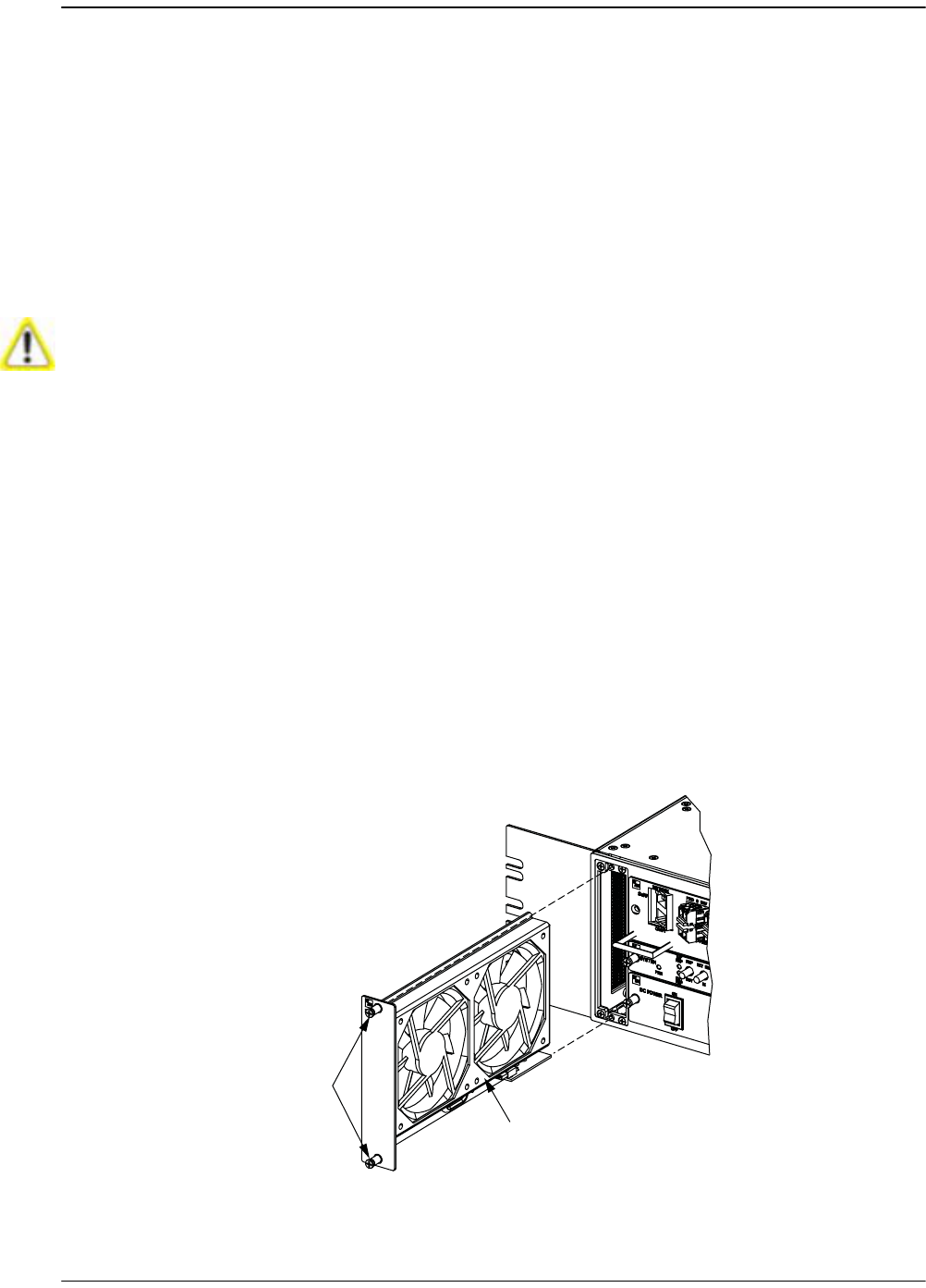
Page 314 FlexWave Prism Host, Remote and EMS 5.1 System Reference
© 2009 ADC Telecommunications, Inc ADCP-77-073 • Issue 2 • 11/2009
A.1 HOST FAN REPLACEMENT PROCEDURE
Continuous airflow for cooling is provided by a fan assembly mounted on the left side
of the Host housing. The cooling fans blow cool air into the enclosure. Heated air is
exhausted through the vent openings on the right side of the enclosure. An alarm is
generated if a high temperature condition (>90º C/122º F) occurs. The fan assembly
may be field-replaced if either fan fails. Replacement of fan assembly does not
require that the Host be turned off.
Recommendation:: The replacement interval for the Host fan is 60 months.
Use the following procedure to remove and replace the Host cooling fans:
11 Notify the NOC or alarm monitoring system operator that the fan is being
replaced.
22 Loosen the two thumb screws that secure the fan/grill assembly to the front of
the Host enclosure.
33 Carefully withdraw the fan/grill assembly from the enclosure.
44 Slide the new fan assembly into the Host chassis until it is firmly seated.
55 Secure the fan/grill assembly to the front of the enclosure using the two screws
loosened in Step 2.
66 Verify that the fans run properly following power-up.
77 Notify the NOC or alarm monitoring system operator that the fans are back in
operation.
Electronic components can be damaged by static electrical discharge. To prevent ESD
damage, slip on an Electrostatic Discharge (ESD) wrist strap and connect the ground wire
to an earth ground source. Wear the ESD wrist strap while completing each step in this
procedure.
22396-A
FAN
ASSEMBLY
THUMB
SCREWS
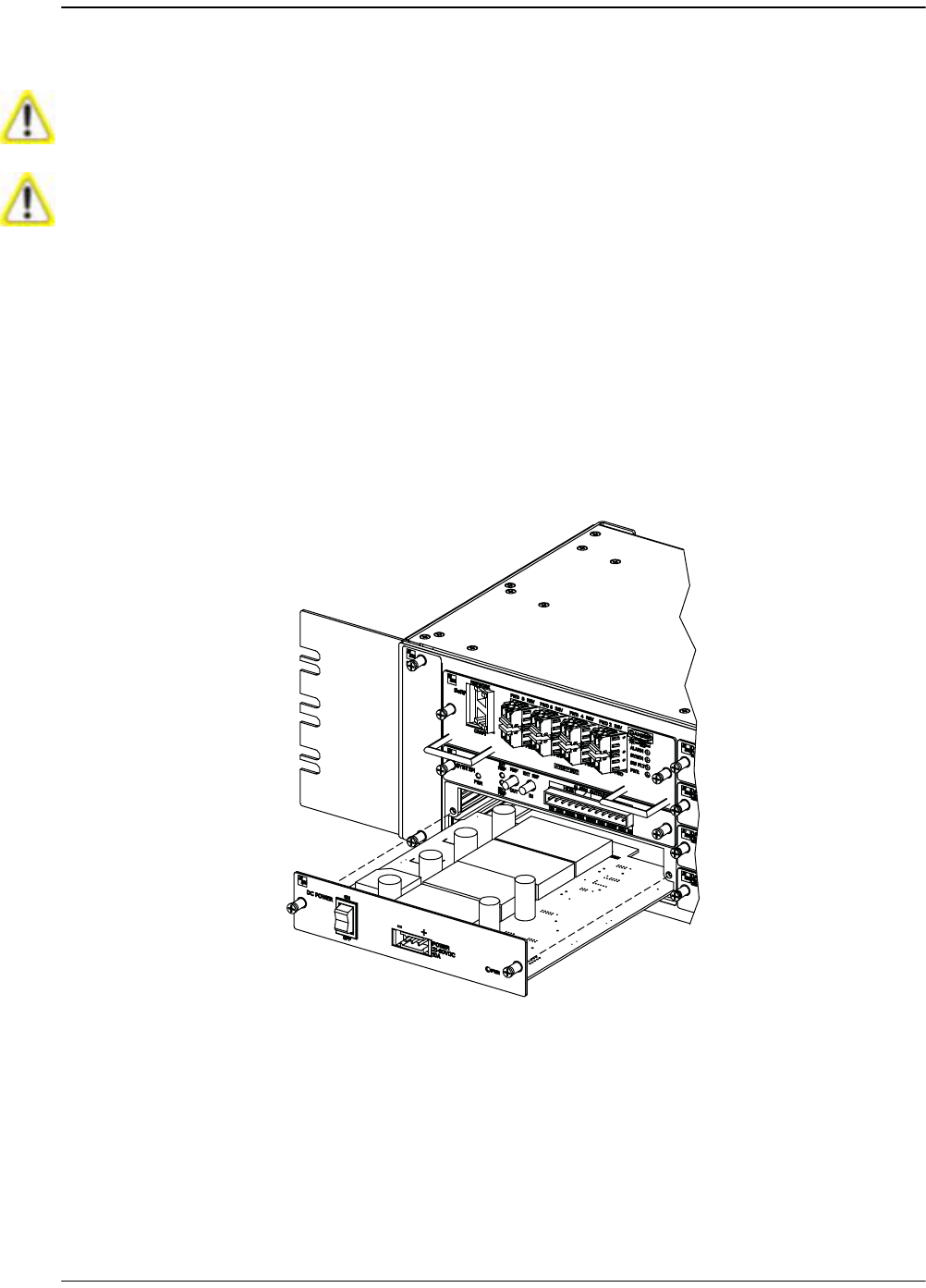
Power Supply Replacement Procedure
FlexWave Prism Host, Remote and EMS 5.1 System Reference Page 315
ADCP-77-073 • Issue 2 • 11/2009 © 2009 ADC Telecommunications, Inc.
A.2 POWER SUPPLY REPLACEMENT PROCEDURE
11 Notify the NOC or alarm monitoring system operator that the system will be out
of service for a period of time.
22 Turn power switch to the OFF position.
33 Unplug power plug by applying pressure to the left and right side of the connector
and pulling it straight out.
44 Loosen the two thumb screws that secure the Power Supply to the front of the
Host enclosure.
55 Carefully withdraw the Power Supply from the enclosure.
66 Slide replacement Power Supply into the Host chassis until it is firmly seated.
77 Secure the Power Supply to the front of the enclosure using the two thumb screws
loosened in Step 4.
88 Verify that the power switch is in its OFF position, and then plug power plug into
the power connector on the front of the Power Supply. Make certain that it is fully
seated.
Removing the power supply disables the Host and interrupts service.
Electronic components can be damaged by static electrical discharge. To prevent ESD
damage, slip on an Electrostatic Discharge (ESD) wrist strap and connect the ground wire
to an earth ground source. Wear the ESD wrist strap while completing each step in this
procedure.
22400-A

Page 316 FlexWave Prism Host, Remote and EMS 5.1 System Reference
© 2009 ADC Telecommunications, Inc ADCP-77-073 • Issue 2 • 11/2009
99 Turn power switch to the ON position.
100 Notify the NOC or alarm monitoring system operator that the system is back in
operation.
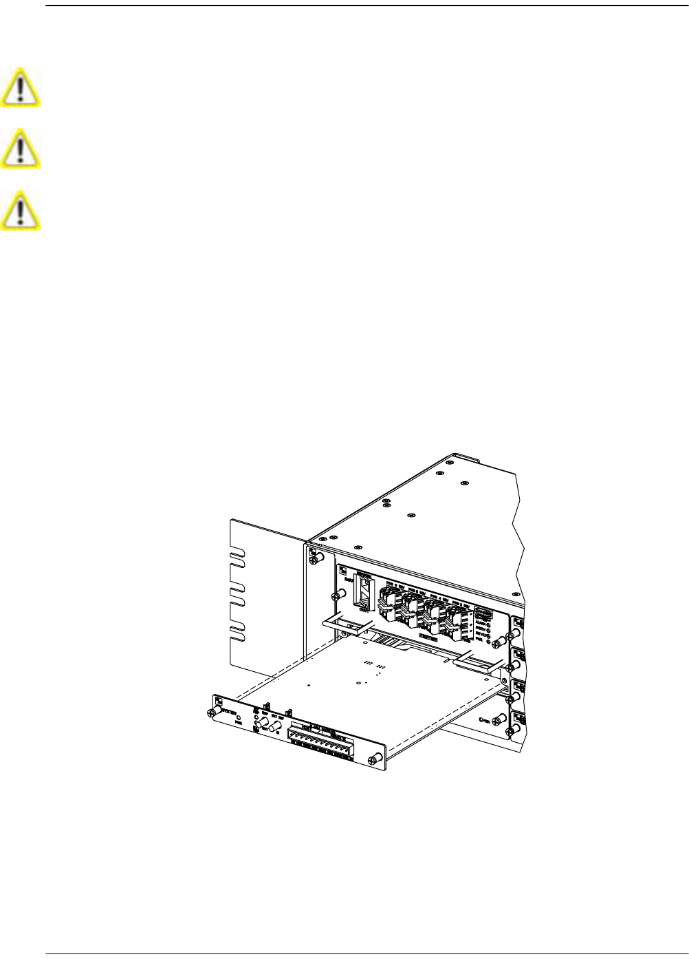
System Card Replacement Procedure
FlexWave Prism Host, Remote and EMS 5.1 System Reference Page 317
ADCP-77-073 • Issue 2 • 11/2009 © 2009 ADC Telecommunications, Inc.
A.3 SYSTEM CARD REPLACEMENT PROCEDURE
11 Notify the NOC or alarm monitoring system operator that the System Card is
being replaced.
22 If used, disconnect EXT REF cables from the front of the System Card.
33 Remove alarm plug from the front of the System Card by pressing on the lock
tabs.
44 Loosen the two thumb screws that secure the System Card to the front of the Host
enclosure.
There will be a Loss of Service during the time it takes to complete this procedure. Notify
the NOC and alarm managers before starting this process.
If the EXT REF is being used communications to other Hosts will be disrupted.
Electronic components can be damaged by static electrical discharge. To prevent ESD
damage, slip on an Electro- Static Discharge (ESD) wrist strap and connect the ground
wire to an earth ground source. Wear the ESD wrist strap while completing each step in
this procedure.
22398-A

Page 318 FlexWave Prism Host, Remote and EMS 5.1 System Reference
© 2009 ADC Telecommunications, Inc ADCP-77-073 • Issue 2 • 11/2009
55 Carefully withdraw the System Card from the enclosure.
66 Slide replacement System Card into the Host chassis until it is firmly seated.
77 Secure the System Card to the front of the enclosure using the two thumb screws
loosened in Step 4.
88 If used, connect EXT REF cables to the front of the System Card.
99 Plug alarm plug into the connector on the System Card.
100 Notify the NOC or alarm monitoring system operator that the system is back in
operation.

SeRF Card Replacement Procedure
FlexWave Prism Host, Remote and EMS 5.1 System Reference Page 319
ADCP-77-073 • Issue 2 • 11/2009 © 2009 ADC Telecommunications, Inc.
A.4 SERF CARD REPLACEMENT PROCEDURE
Replacing the SeRF card is a 14-step procedure that is broken into four sections,
Follow the steps in the order given.
A.4.1 Preserve System Configuration
11 Before you start the procedure to replace the SeRF card, decide how you will
restore the system configuration, which can be accomplished in one of two ways:
•• Option A—You can remove the Compact Flash card from the old SeRF and
install it into the new SeRF before installing the SeRF card in the Host.
•• Option B—You can reconfigure the system once the new SeRF is installed. If
you are going to reconfigure the system, before you remove the SeRF card,
record the system settings in Table A-1, including frequency bands, gain and
delay settings, module names and network information.
Removing the SeRF Card will disable the Host and interrupt service. The entire system
configuration is stored on the Compact Flash card on the SeRF. If you replace the SeRF
with a new one, the system will NOT be operational immediately following replacement.
Notify the NOC or alarm monitoring system operator that the system will be Out of
Service (OOS) for a period of time.
Table A-1. URH System Configuration
EMS VIEW PARAMETER SETTING
IP ADDRESSES
Host Network port IP address
Host Craft port IP address
Remote 1 IP address
Remote 2 IP address
Remote 3 IP address
Remote 4 IP address
Remote 5 IP address
Remote 6 IP address
Remote 7 IP address
Remote 8 IP address
HOST CONFIGURATION
Host Summary Host Name
10 MHz Reference Clock
Optical Ports view for the Host Optical Port 1 name
Optical Port 2 name
Optical Port 3 name
Optical Port 4 name

Page 320 FlexWave Prism Host, Remote and EMS 5.1 System Reference
© 2009 ADC Telecommunications, Inc ADCP-77-073 • Issue 2 • 11/2009
Optical Port 5 name
Optical Port 6 name
Optical Port 7 name
Optical Port 8 name
Configuration and Alarm Details
of DART 1
DART Name
DART Pass Band
DART Operating Mode
DART Diversity Status list
DART Forward Gain
DART Reverse Gain
Configuration and Alarm Details
of DART 2
DART Name
DART Pass Band
DART Operating Mode
DART Diversity Status list
DART Forward Gain
DART Reverse Gain
Configuration and Alarm Details
of DART 3
DART Name
DART Pass Band
DART Operating Mode
DART Diversity Status list
DART Forward Gain
DART Reverse Gain
Configuration and Alarm Details
of DART 4
DART Name
DART Pass Band
DART Operating Mode
DART Diversity Status list
DART Forward Gain
DART Reverse Gain
Configuration and Alarm Details
of DART 5
DART Name
DART Pass Band
DART Operating Mode
DART Diversity Status list
DART Forward Gain
DART Reverse Gain
Configuration and Alarm Details
of DART 6
DART Name
Table A-1. URH System Configuration (Cont.)
EMS VIEW PARAMETER SETTING

SeRF Card Replacement Procedure
FlexWave Prism Host, Remote and EMS 5.1 System Reference Page 321
ADCP-77-073 • Issue 2 • 11/2009 © 2009 ADC Telecommunications, Inc.
DART Pass Band
DART Operating Mode
DART Diversity Status list
DART Forward Gain
DART Reverse Gain
Configuration and Alarm Details
of DART 7
DART Name
DART Pass Band
DART Operating Mode
DART Diversity Status list
DART Forward Gain
DART Reverse Gain
Configuration and Alarm Details
of DART 8
DART Name
DART Pass Band
DART Operating Mode
DART Diversity Status list
DART Forward Gain
DART Reverse Gain
REMOTE CONFIGURATION
Remote Unit view Remote Name
Optical Ports view for Remote n Optics Port Name
Configuration Details window DART name
Remote Dart Id
Remote Dart SFP Id
DART Forward Gain
DART Forward Delay
DART Reverse Delay
LPA Operating Mode
Table A-1. URH System Configuration (Cont.)
EMS VIEW PARAMETER SETTING
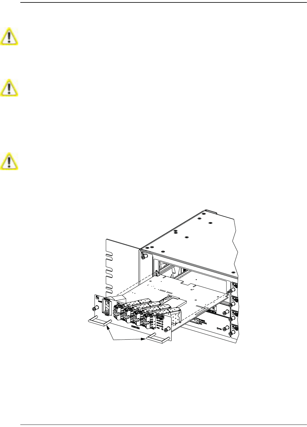
Page 322 FlexWave Prism Host, Remote and EMS 5.1 System Reference
© 2009 ADC Telecommunications, Inc ADCP-77-073 • Issue 2 • 11/2009
A.4.2 Remove the SeRF Card
22 Remove Network and Craft RJ-45 plugs from the front of the SeRF Card.
33 Remove fiber patch cord from the SFPs. Note the location of the fiber patch cords.
44 Loosen the two thumb screws that secure the System Card to the front of the Host
enclosure.
55 Use the two handles to carefully withdraw the SeRF Card from the enclosure.
Electronic components can be damaged by static electrical discharge. To prevent ESD
damage, slip on an Electrostatic Discharge (ESD) wrist strap and connect the ground wire
to an earth ground source. Wear the ESD wrist strap while completing each step in this
procedure.
This equipment uses a Class 1 Laser according to FDA/CDRH rules. Laser radiation can
seriously damage the retina of the eye. Do not look into the ends of any optical fiber. Do
not look directly into the optical transmitter of any unit or exposure to laser radiation
may result. An optical power meter should be used to verify active fibers. A protective
cap or hood MUST be immediately placed over any radiating transmitter or optical fiber
connector to avoid the potential of dangerous amounts of radiation exposure. This
practice also prevents dirt particles from entering the connector.
Improper handling can damage fiber optic cables. Do not bend fiber optic cable more
sharply than the minimum recommended bend radius specified by the cable
manufacturer. Do not apply more pulling force to the cable than specified.
22397-A
HANDLES
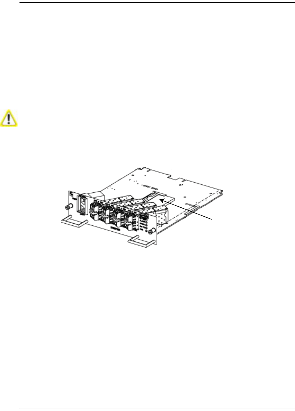
SeRF Card Replacement Procedure
FlexWave Prism Host, Remote and EMS 5.1 System Reference Page 323
ADCP-77-073 • Issue 2 • 11/2009 © 2009 ADC Telecommunications, Inc.
66 Do one of the following:
•• If you plan to reconfigure the system once the new SeRF is installed, skip to
Section A.5.2, Installing a New DART Card in the Host Chassis, on page 325.
•• If you will be removing the Compact Flash card from the old SeRF and
installing it into the new SeRF before installing the SeRF card in the Host, go
to Section A.4.3, Swap Compact Flash From Old SeRF Card to New SeRF Card,
on page 323.
A.4.3 Swap Compact Flash From Old SeRF Card to New
SeRF Card
77 Remove the Compact Flash card from the new SeRF card by gently lifting the
Compact Flash card out of its holder.
88 Slide the Compact Flash removed from the old SeRF card into the new SeRF card.
Install the Compact Flash card label side up, and with the connectors pointing
toward the middle of the SeRF card. Gently push the Compact Flash card in until
it is firmly seated.
Do not complete this procedure if you are going to reconfigure the URH system after you
install the new SeRF card—skip to “Install New SeRF Card” on page 324.
75348p2-0001
Compact Flash card
SeRF card

Page 324 FlexWave Prism Host, Remote and EMS 5.1 System Reference
© 2009 ADC Telecommunications, Inc ADCP-77-073 • Issue 2 • 11/2009
A.4.4 Install New SeRF Card
99 Slide replacement SeRF Card into the Host chassis until it is firmly seated.
100 Secure the SeRF Card to the front of the enclosure using the two thumb screws
loosened in Step 4.
111 If necessary, install new SFPs or remove them from the SeRF card removed in
Step 5 and install them in the new SeRF Card.
122 Plug fiber patch cords back into the SFPs, making sure that you return the fiber
patch cords to the position they were in prior to this procedure.
133 Plug Network and Craft RJ-45 plugs into the connector on the SeRF Card. Make
certain the fiber patch cords are inserted in the correct SFP.
144 Notify the NOC or alarm monitoring system operator that the system is back in
operation.
If you are going to swap the Compact Flash card from the old SeRF card to the new,
before starting this procedure, complete the steps in “Swap Compact Flash From Old
SeRF Card to New SeRF Card” on page 323.

DART Card Replacement/Installation Procedure
FlexWave Prism Host, Remote and EMS 5.1 System Reference Page 325
ADCP-77-073 • Issue 2 • 11/2009 © 2009 ADC Telecommunications, Inc.
A.5 DART CARD REPLACEMENT/INSTALLATION
PROCEDURE
Each DART card is spectrum specific and provides an interface between the SeRF and
the Power Amplifier. When additional service is needed another DART card can be
added to the Host. Individual DART cards may be replaced without disrupting service
to the entire remote system. Only the RF spectrum of the DART card being removed
is affected.
A.5.1 Replacing a DART Card in the Host Chassis
11 Notify the NOC or alarm monitoring system operator that the DART card is being
replaced.
22 Disconnect REF IN and OUT cables from the front of the DART card.
33 Loosen the two thumb screws that secure the DART card to the front of the Host
enclosure.
44 Carefully withdraw the DART card from the enclosure.
55 Slide replacement DART card into the Host chassis until it is firmly seated.
66 Secure the DART card to the front of the enclosure using the two thumb screws
loosened in Step 3.
77 Connect REF IN and OUT cables to the front of the DART card.
88 Notify the NOC or alarm monitoring system operator that the system is back in
operation.
A.5.2 Installing a New DART Card in the Host Chassis
11 Notify the NOC or alarm monitoring system operator that another DART card is
being added the Host.
22 Determine slot location of the new DART card. See Figure 1-6 on Page 14 for DART
card slot assignments.
If you replace or install a DART card in the Host to change the RF, its equivalent must
be replaced or added to the Remote by adding or replacing the corresponding Remote
RF Module.
Electronic components can be damaged by static electrical discharge. To prevent ESD
damage, slip on an Electrostatic Discharge (ESD) wrist strap and connect the ground wire
to an earth ground source. Wear the ESD wrist strap while completing each step in this
procedure.
Electronic components can be damaged by static electrical discharge. To prevent ESD
damage, slip on an Electrostatic Discharge (ESD) wrist strap and connect the ground wire
to an earth ground source. Wear the ESD wrist strap while completing each step in this
procedure.
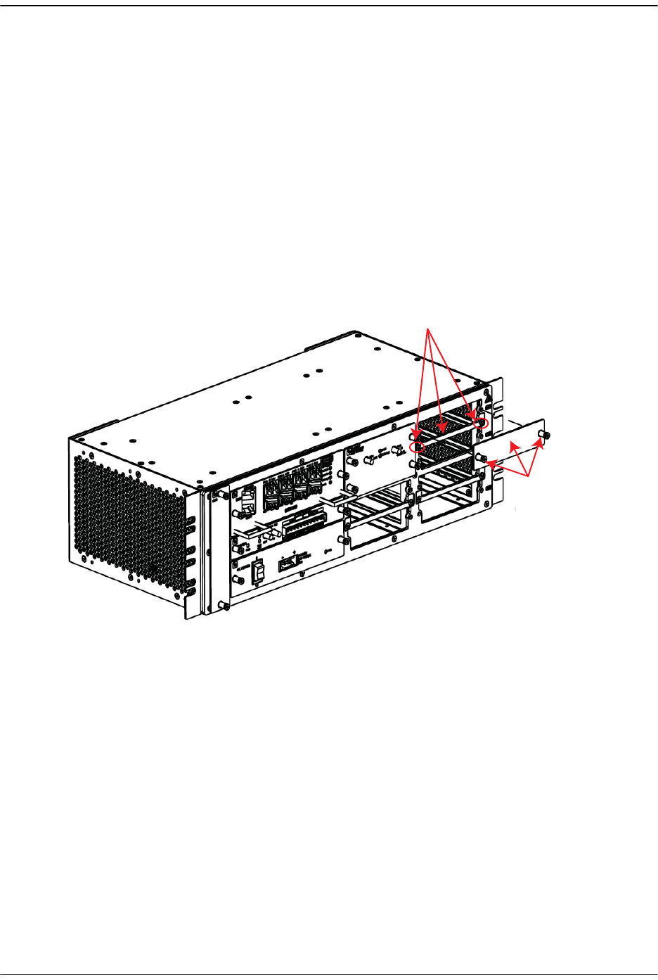
Page 326 FlexWave Prism Host, Remote and EMS 5.1 System Reference
© 2009 ADC Telecommunications, Inc ADCP-77-073 • Issue 2 • 11/2009
33 Remove from the front of the Host the blank panel that corresponds to the
selected slot location.
44 Do one of the following:
•• If you are installing a Dual SuperDART card:
aa Loosen the two retaining screws on the front of the blank panel and then
then remove the blank panel.
bb Use a Phillips screwdriver to remove the two screws from the divider bar,
and then remove the divider bar, storing the bar and screws for potential
future use.
•• If a Dual SuperDART card had previously been installed and you are now
installing a Single SuperDART or Classic DART, use two Phillips-head screws
to reinstall a divider bar.
Blank Panel with
2 Retaining Screws
Divider Bar with
2 Philips-Head Screws
77073-079
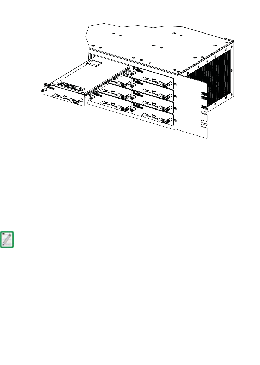
DART Card Replacement/Installation Procedure
FlexWave Prism Host, Remote and EMS 5.1 System Reference Page 327
ADCP-77-073 • Issue 2 • 11/2009 © 2009 ADC Telecommunications, Inc.
55 Slide the DART card into the Host chassis until it is firmly seated.
66 Secure the DART card to the front of the enclosure using the two thumb screws.
77 Obtain the required lengths of high performance, flexible, low loss 50-ohm coaxial
communications cable (RG-400 or equivalent) for all coaxial connections.
88 Route the forward and reverse path coaxial cables between the Host and the BTS
interface (per system design plan) and cut to the required length. Allow sufficient
slack for dressing and organizing cables at the Host and for installing an external
attenuator in the forward path link.
99 Terminate each cable with an QMA-type male connector following the connector
supplier’s recommendations.
100 If required, install an external attenuator in the forward path.
111 Connect the forward and reverse path cables as shown as shown in Step 21 in
Section 3.3.5, Coaxial Cable Connections, on page 70:
aa Connect the forward path cable to the FWD RF IN connector on the Host DART
front panel.
bb Connect the reverse path cable to the REV RF OUT connector on the Host DART
front panel.
122 Dress and secure cables at the right side of the Host.
133 Complete all remaining coaxial connections as specified in the system design
plan.
144 Notify the NOC or alarm monitoring system operator that the DART card is ready
for operation.
The composite forward path RF signal level at the Host must be between –25 and + 5
dBm. Do not connect the forward path cable until the composite forward path RF signal
level is measured and the amount of external attenuation required is determined.
22401-A

Page 328 FlexWave Prism Host, Remote and EMS 5.1 System Reference
© 2009 ADC Telecommunications, Inc ADCP-77-073 • Issue 2 • 11/2009
Intentionally Blank Page

FlexWave Prism Host, Remote and EMS 5.1 System Reference Page 329
ADCP-77-073 • Issue 2 • 11/2009 ©2009 ADC Telecommunications, Inc.
BGENERAL INFORMATION
B.1 Warranty/Software...........................................................................................329
B.2 Software Service Agreement..............................................................................329
B.3 Repair/Exchange Policy .....................................................................................329
B.4 Repair Charges ................................................................................................330
B.5 Replacement/Spare Products .............................................................................330
B.6 Returned Material.............................................................................................330
B.1 WARRANTY/SOFTWARE
The Product and Software warranty policy and warranty period for all ADC Products
is published in ADC’s Warranty/Software Handbook. Contact the Technical
Assistance Center at 1-800-366-3891, extension 73476 (in U.S.A. or Canada) or
952-917-3476 (outside U.S.A. and Canada) for warranty or software information or
for a copy of the Warranty/Software Handbook.
B.2 SOFTWARE SERVICE AGREEMENT
ADC software service agreements for some ADC Products are available at a nominal
fee. Contact the Technical Assistance Center at 1-800-366-3891, extension 73476 (in
U.S.A. or Canada) or 952-917-3476 (outside U.S.A. and Canada) for software service
agreement information.
B.3 REPAIR/EXCHANGE POLICY
All repairs of ADC Products must be done by ADC or an authorized representative.
Any attempt to repair or modify ADC Products without written authorization from
ADC voids the warranty.
If a malfunction cannot be resolved by the normal troubleshooting procedures, call
the Technical Assistance Center at 1-800-366-3891, extension 73476 (in U.S.A. or
Canada) or 952-917-3476 (outside U.S.A. and Canada). A telephone consultation can
sometimes resolve a problem without the need to repair or replace the ADC Product.
Content Page

Page 330 FlexWave Prism Host, Remote and EMS 5.1 System Reference
© 2009 ADC Telecommunications, Inc ADCP-77-073 • Issue 2 • 11/2009
If, during a telephone consultation, ADC determines the ADC Product needs repair,
ADC will authorize the return of the affected Product for repair and provide a Return
Material Authorization number and complete return shipping instructions. If time is
critical, ADC can arrange to ship the replacement Product immediately. In all cases,
the defective Product must be carefully packaged and returned to ADC.
B.4 REPAIR CHARGES
If the defect and the necessary repairs are covered by the warranty, and the applicable
warranty period has not expired, the Buyer’s only payment obligation is to pay the
shipping cost to return the defective Product. ADC will repair or replace the Product
at no charge and pay the return shipping charges.
Otherwise, ADC will charge a percentage of the current Customer Product price for
the repair or NTF (No Trouble Found). If an advance replacement is requested, the full
price of a new unit will be charged initially. Upon receipt of the defective Product,
ADC will credit Buyer with 20 percent of full price charged for any Product to be
Out-of-Warranty. Products must be returned within thirty (30) days to be eligible for
any advance replacement credit. If repairs necessitate a visit by an ADC
representative, ADC will charge the current price of a field visit plus round trip
transportation charges from Minneapolis to the Buyer’s site.
B.5 REPLACEMENT/SPARE PRODUCTS
Replacement parts, including, but not limited to, button caps and lenses, lamps,
fuses, and patch cords, are available from ADC on a special order basis. Contact the
Technical Assistance Center at 1-800-366-3891, extension 73476 (in U.S.A. or Canada)
or 952-917-3476 (outside U.S.A. and Canada) for additional information.
Spare Products and accessories can be purchased from ADC. Contact Sales
Administration at 1-800-366-3891, extension 73000 (in U.S.A. or Canada) or
1-952-938-8080 (outside U.S.A. and Canada) for a price quote and to place your order.
B.6 RETURNED MATERIAL
Contact the ADC Product Return Department at 1-800-366-3891, extension 73748 (in
U.S.A. or Canada) or 952-917-3748 (outside U.S.A. and Canada) to obtain a Return
Material Authorization number prior to returning an ADC Product.
All returned Products must have a Return Material Authorization (RMA) number
clearly marked on the outside of the package. The Return Material Authorization
number is valid for 90 days from authorization.

FlexWave Prism Host, Remote and EMS 5.1 System Reference Page 331
ADCP-77-073 • Issue 2 • 11/2009 ©2009 ADC Telecommunications, Inc.
CGLOSSARY
Alarm
A physical or functional state affecting the ability of a Host/Remote pair to function normally.
Reported by the Host/Remote pair to the EMS to notify the user that such a state exists.
Attenuation
Function applied to an RF signal to lower the signal level. Can be set for a Host/Remote pair
using an EMS window or command.
Band
RF spectrum defined as an entity for communication purposes and assignable to a service
provider for cell phones and similar devices. Examples are Cellular and PCS.
Base Transceiver Station
Signal processing station at the base of a tower or at some other location with access to the
main antenna. Its primary function is to transport RF signals between the main antenna and
cell phone users.
BTS
See Base Transceiver Station.
DART
Digital to Analog Receiver Transmitter. Interface card used in both Host and Remotes. Its
primary function is data conversion of RF to optical and vice versa. Each DART provides one
RF band.
Delay
RF propagation delay, which can be set for a linked Host DART and Remote DART using an
EMS window or command.
EMS
FlexWave Prism Element Management System, the software application documented in this
document.
ENET Port
Ethernet port capable of CAT5 transmission.

Page 332 FlexWave Prism Host, Remote and EMS 5.1 System Reference
© 2009 ADC Telecommunications, Inc ADCP-77-073 • Issue 2 • 11/2009
Forward Path
Signal path in the direction from the BTS to the cell phone.
Hypertext Transfer Protocol (HTTP)
HTTP is a is a request/response standard used by the World Wide Web in which the WWW is
a web site is the server and the end user is the client. The EMS uses HTTP to allow access to a
Host or Remote through its IP address.
Host Unit
FlexWave Prism network element that receives an RF signal from the BTS and converts it to
an optical signal to its paired Remotes.
Linear Power Amplifier(LPA)
An electronic module in the Remote. Its job is to provide a large power gain to forward path
signals.
LNA
Low Noise Amplifier. An electronic module in the Remote. The LNA amplifies the reverse path
RF signal.
Log File
EMS history file into which alarms are written as they occur. It can be used to review recent
alarms.
Mask
A software setting placed on an alarm type that causes all alarms of this type to not be reported
in the EMS. The LEDs for a masked alarm display in gray instead of the standard red, yellow,
and green.
Normal Mode
One of the operating modes of the DART and LPA. In this mode the equipment is transporting
RF signals normally.
Radio Frequency
(RF) Radio-type frequency modulation signal received at the BTS and transmitted from the
Remote to the cell phone.
Reverse Path
Signal path in the direction from the cell phone to the BTS.
Remote Unit
FlexWave Prism network element that receives an optical signal from its paired Host, converts
the optical signal to RF, and transmits the RF signal to cell phones in a local coverage area.
RF Signal Level
Measured power of the forward path and reverse path RF signals as measured in the
Host/Remote pair and reported in the EMS.

FlexWave Prism Host, Remote and EMS 5.1 System Reference Page 333
ADCP-77-073 • Issue 2 • 11/2009 © 2009 ADC Telecommunications, Inc.
Standby Mode
One of the operating modes of the DART and LPA. In this mode, RF transport is disabled and
power consumption is minimized.
Threshold
Value that defines when a reported state in the Host/Remote pair is considered to be in alarm.
URH
Universal Radio Head. This name derives from the ability of a FlexWave URH Remote to
support multiple bands of different types.

Page 334 FlexWave Prism Host, Remote and EMS 5.1 System Reference
© 2009 ADC Telecommunications, Inc ADCP-77-073 • Issue 2 • 11/2009
Intentionally Blank Page
FlexWave Prism Host, Remote and EMS 5.1 System Reference Page 335
ADCP-77-073 • Issue 2 • 11/2009 ©2009 ADC Telecommunications, Inc.
DCONTACTING ADC
13944-Q
Contents herein are current as of the date of publication. ADC reserves the right to change the contents
without prior notice. In no event shall ADC be liable for any damages resulting from loss of data,
loss of use, or loss of profits and ADC further disclaims any and all liability for indirect, incidental,
special, consequential or other similar damages. This disclaimer of liability applies to all products,
publications and services during and after the warranty period.
REPRINTS:
www.adc.com/manuals
PDF copies of manuals are available
for downloading at the following link:
PRODUCT INFORMATION AND TECHNICAL ASSISTANCE:
connectivity.tac@adc.com
wireless.tac@adc.com
euro.tac@adc.com
asiapacic.tac@adc.com
ADCP Number:
WRITE:
ADC Telecommunications (S’PORE) PTE, LTD;
100 Beach Road, #18-01, Shaw Towers.
Singapore 189702.
ADC Telecommunications, INC
PO Box 1101,
Minneapolis, MN 55440-1101, USA
ADC European Customer Service, INC
Belgicastraat 2,
1930 Zaventem, Belgium
77-073
PHONE :
U.S.A. or CANADA
Sales: 1-800-366-3891
Extension 73000
Technical Assistance: 1-800-366-3891
Connectivity Extension: 73475
Wireless Extension: 73476
EUROPE
Sales Administration: +32-2-712-65 00
Technical Assistance: +32-2-712-65 42
EUROPEAN TOLL FREE NUMBERS
Germany: 0180 2232923
UK: 0800 960236
Spain: 900 983291
France: 0800 914032
Italy: 0800 782374
ASIA/PACIFIC
Sales Administration: +65-6294-9948
Technical Assistance: +65-6393-0739
ELSEWHERE
Sales Administration: +1-952-917-3000
Technical Assistance: +1-952-917-3475

Page 336 FlexWave Prism Host, Remote and EMS 5.1 System Reference
© 2009 ADC Telecommunications, Inc ADCP-77-073 • Issue 2 • 11/2009
Intentionally Blank Page

FlexWave Prism Host, Remote and EMS 5.1 System Reference Page 337
ADCP-77-073 • Issue 2 • 11/2009 ©2009 ADC Telecommunications, Inc.
INDEX
Numerics
10 MHz Reference Clock list ................... 148
4G readiness ..............................................4
A
AC power junction box ........................... 126
AC power port ........................................ 128
AC Power Supply Fault LED .................... 242
AC power wiring, Remote ................125–128
Access
Network Manager ............................. 200
Network User ................................... 200
Access Level list ..................................... 200
Accessing
EMS ................................................. 188
FlexWave-URH Agent MIB ................ 282
AccessLevel column ............................... 197
ADC-FLEXWAVE-URH.mib ...................... 280
Add New User link .......................... 197,199
add user ................................................ 200
admin user access ................................. 196
Agent SwVer column, System Inventory table
............................................................ 181
Alarm
Major, DARTs ................................... 253
Alarm Details of DART-n of Group n on
Remote-n window ........ 236–237,253–254
Alarm Indications ...................................141
Alarm Management Table window .. 260,262
Alarm Summary indicator .......................178
Alarm Summary of RF Groups of Remote-n
view ............................................ 250–251
Alarm Type column ................................258
Alarms
Minor, DARTs ...................................254
Antenna cable, Remote .................. 123–125
Applications, FlexWave Prism .................... 5
Apply button .............................................xi
APPMon SwVER column, System Inventory
table ...................................................181
Auto Refresh list .....................................179
Auto Refresh Time box ...........................179
AWS bandwidths ................................ 24–25
B
Band-Config link ............................. 152,168
Bandwidths
AWS ............................................. 24–25
DART cards .................................. 20–23
options ......................................... 20–23
PCS .............................................. 24–25
versus timeslots .................................19

Page 338 FlexWave Prism Host, Remote and EMS 5.1 System Reference
© 2009 ADC Telecommunications, Inc ADCP-77-073 • Issue 2 • 11/2009
Boot Loader Ver column, System Inventory
table ................................................... 181
C
Canceling a procedure ............................... xi
Caution icon ...............................................x
Change Access Level button ........... 197,203
Change Access Level window ................. 203
Change password
another user .............................206–207
your own ......................................... 208
Change Password button .197,206,207,208
Change Password Settings view
changing another’s password ........... 206
changing your password .................. 208
Chassis ground
Host ...................................................69
Remote ...................................... 118–??
Class column, SNMP interface ................ 291
Clock source, setting .......................147–149
Close button ............................................. xi
Coaxial cable
install, Host ................................. 70–71
Compact Flash SwVer column, System
Inventory table ................................... 181
Components
Prism system .......................................6
Remote Unit .......................................36
Configuration and Alarm Details of Dart n on
Host-n window .................................... 226
Configuration and Alarm Details window 153,
............................................................ 170
Configuration Details table ..................... 163
Configuration link ................................... 179
Configuring Host DARTs ..................152–155
Confirmation dialog
decommissioning a Host DART .........221
decommissioning a Remote DART .... 234
decommissioning a Remote Unit ......245
delete user .......................................210
reset Host Unit .................................216
reset unit .........................................247
Connect to dialog
local login
Host ...........................................193
Remote ......................................191
remote log in ...................................188
Connectors
Remote ........................................ 47–48
Course Wavelength Division Multiplexer
System ............................................ 51–54
Craft port
Host ...................................................80
Craft Port status, Host ............................218
D
DART alarm ............................................250
DART cards
alarms
Major .........................................253
Minor .........................................254
bandwidths .................................. 20–23
configuring ............................... 152–155
decommissioning
Host ................................... 220–221
Remote ............... 232–234,244–245
install, Host .............................. 325–327
linking ...................................... 162–166
overview ...................................... 12–15
unlink ...............................................173
DART DC Supply Fault ............................253
DART Diversity Status list 153,154,171,173,
............................................................174
DART Fault
Host .................................................227
Remote ............................................253
DART Forward Delay box ........................166
DART Forward Gain list ........................... 165

FlexWave Prism Host, Remote and EMS 5.1 System Reference Page 339
ADCP-77-073 • Issue 2 • 11/2009 © 2009 ADC Telecommunications, Inc.
DART Hardware Mismatch Fault
Host ................................................. 227
Remote ............................................ 253
DART Indicator ....................................... 214
DART Low Temperature Fault ................. 254
DART Name box ......................153,170,173
DART Operating Mode list .......153,171,173
DART Over Drive Fault ........................... 227
DART Over Temperature Fault ............... 253
DART Pass Band (Timeslots) list .... 153,170,
173
DART Remote Ranging Fault .................. 253
DART Reverse Delay box ........................ 166
DART Reverse Gain list .......................... 154
DART UnderDrive Fault .......................... 227
Date Code column
Host Inventory table ........................ 182
Remote Inventory table ................... 183
Date column, SNMP interface ................. 291
Decommission button ............................ 163
Decommission Unit button ..................... 243
Decommissioning
Host DART ................................220–221
Remote DART ............232–234,244–245
Delete Entry button ................................ 291
Delete the Selected Rows ....................... 291
Delete User button ......................... 197,210
Determine power, Remote ..............129–131
Diversity reverse path ..............................17
Divider bar, Host Unit ............................ 326
Duplexer, remote .....................................40
E
E911 Support ...........................................16
E911 support ............................................16
EMS Menu bar ................................ 138,140
EMS View Frame ....................................138
Enable Logging check box ......................291
ENET Configurations view
Host ......................................... 217–219
Remote .................................... 230–231
ENETMon SwVer column, System Inventory
table ...................................................181
Ethernet CAT 5 cable ..............................142
EXT REF connections, Host ................. 78–79
F
Fan Over Speed Fault .............................242
Fan Under Speed Fault ...........................242
Fan, Host ...............................................314
Fiber Optic Transport .......................... 17–18
Finishing a procedure ................................xi
FlexWave URH EMS ................................... 4
FlexWave-URH Agent MIB
accessing .........................................282
GET/SET Objects ...................... 292–307
Traps ....................................... 308–310
Fonts .........................................................xi
Forward path optical signal .......................17
FPGA Ver column, System Inventory table ..
181
FPGAMon SWVer column, System Inventory
table ...................................................182
Function Explorer Tree ...........................138
Fwd Launch column

Page 340 FlexWave Prism Host, Remote and EMS 5.1 System Reference
© 2009 ADC Telecommunications, Inc ADCP-77-073 • Issue 2 • 11/2009
Host ................................................. 225
Remote ............................................ 249
G
General Configuration window ................ 179
Graphical User Interface, overview ........ 138
Green LED .............................................. 141
Grey LED ............................................... 141
H
Handset interface, remote ........................36
Host ....................................................... 168
Host Dart Band column .......................... 163
Host Dart Id column ............................... 163
Host Dart Pass Band column .................. 163
Host Dart SFP Id column ........................ 163
Host DART Status column ...................... 163
Host DART’s Alarm Summary view 152,168,
220,.............................................226–227
Host DARTs, configuring .................152–155
Host ENET Configurations view .......217–219
Host IP Address field .............................. 178
Host Lost Fault LED ................................ 242
Host Major Contact Alarm Output Indicator .
214
Host Minor Contact Alarm Output Indicator .
214
Host mounting brackets ..................... 66–67
Host Name box ...................................... 147
Host Name column ................................. 258
Remote ............................................ 249
Host Name, creating .......................147–149
Host Name, Function Explorer Tree ........148
Host No column ......................................258
Host SERF optical ports, labeling ............151
Host Summary view ................147–149,214
Host Temperature Measurement ............223
Host Unit
DARTs
decommissioning ............... 220–221
linking to Remote ............... 162–166
front panel ................................... 30–33
network connection ............................33
overview ............................................30
resetting .................................. 215–216
RF signal connections .........................33
specifications .....................................56
system card .......................................34
Host Unit Name field ..............................178
Hw Ver column
Host Inventory table ........................182
Remote Inventory table ...................183
HWMon SwVer column, System Inventory
table ...................................................181
I
Icons ......................................................... x
Illustrations ...............................................xi
Indoor coverage ........................................ 4
Information column ........................ 152,168
Installation
Host
chassis ground .............................69
Coaxial cable .......................... 70–71
Craft port .....................................80
EXT REF connections .............. 78–79
Optical connections ................ 72–77
Optical connections, no WDM .74–75
Optical connections, with WDM .76–
77
OSP Fiber cable ............................68
Power connections ................. 83–86
System Alarm connections ..... 81–83
WDM components .................. 90–91

FlexWave Prism Host, Remote and EMS 5.1 System Reference Page 341
ADCP-77-073 • Issue 2 • 11/2009 © 2009 ADC Telecommunications, Inc.
Host DART card ........................325–327
Host fan ........................................... 314
Host into equipment rack ............. 66–67
Host power supply ........................... 315
Host SeRF card .........................319–324
Host system card ......................317–318
Remote
AC power wiring .................125–128
Antenna cable .....................123–125
determine power ................129–131
ground wire ......................... 118–??
mounting plans ............................96
Network cable .....................119–120
Quad Fiber cable .................121–123
RF Module ............................ 98–??, 106
Installation prerequisites
Host ...................................................64
Internet Explorer ................................... 142
IP Address field ...................................... 178
Ip Enable ....................................... 151,249
setting, Remotes .............................. 158
IpEnable Fault ........................................ 225
L
Labeling
Host SERF optical ports .................... 151
Host Unit ..................................147–148
Remote .....................................156–157
Laser Fault column
Host ................................................. 225
Remote ............................................ 249
LC Attenuator ...........................................73
LEDs, alarms .......................................... 141
Lightning Surge Suppressor ..................... 50
Linear Power Amplifier, Remote ............... 41
Linking ................................................... 159
Remote DART to Host DART ......162–166
remote DART to Host DART ......162–166
Linux Kernel Ver column, System Inventory
table ................................................... 181
LNA alarm .............................................. 251
LNA Major Alarms ...................................254
LNA Power Fault .....................................254
LongRange
Host .................................................225
Remote ............................................249
Low Noise Amplifier, remote .....................40
LPA
restarting ................................. 236–239
LPA alarm ...............................................250
LPA DC Fault ..........................................254
LPA Resets .......................................237
LPA Disable Fault ....................................254
LPA Resets .......................................236
LPA High Temperature Fault ...................254
LPA Loop Fault .......................................254
LPA Resets .......................................237
LPA Low Power Fault ..............................254
LPA Resets .......................................237
LPA Major Alarms ...................................254
LPA Minor Alarms ...................................254
LPA Missing Fault ........................... 237,254
LPA Over Power Fault .............................254
LPA Resets .......................................237
LPA Reset button ............................ 163,236
LPA VSWR Fault .....................................254
LPA Resets .......................................237
M
Major alarms ..........................................141
Major Alarms table .................................242
Management Port status .........................218
Masking alarm types ..............................260
MATEMon SwVER column, System Inventory
table ...................................................181

Page 342 FlexWave Prism Host, Remote and EMS 5.1 System Reference
© 2009 ADC Telecommunications, Inc ADCP-77-073 • Issue 2 • 11/2009
Materials
Host installation .................................65
Remote installation ............................95
Menu bar ............................................... 140
Message, SNMP interface ....................... 291
MIB ........................................................ 278
MIB browser ........................................... 281
Millimeter wave backhaul ...........................4
Millimeter Wave System ...........................55
Minor alarms .......................................... 141
Minor Alarms table ................................. 242
Module Number column ......................... 258
Module Type column .............................. 258
Host Inventory table ........................ 182
Remote Inventory table ................... 183
Module Type column, System Inventory table
............................................................ 181
Mounting brackets, remote ......................46
Mounting plans, Remote ..........................96
Multi Fibers ............................................ 159
Multi-Host system
overview ...................................... 10–11
Multi-Host Systems ..................................10
N
Network cable, Remote ...................119–120
Network Interface Card .......................... 142
Network Interface list ............................. 149
Network Manager access level ............... 196
Network Manager role ............................ 200
Network Manager, assign role of ............ 200
Network Port status
Host .................................................218
Network User
assign role of ...................................200
change user role ..............................203
Network User access level ......................196
Network User role ..................................200
networkManager
add user ...........................................200
change user account ........................203
networkUser ...........................................200
change user account ........................203
New Link list
Host DARTs ......................................173
New Password box ..................200,207,208
Normal mode ..........................153,171,173
Note icon ................................................... x
O
OK button .................................................xi
Old Password box ...................................208
Open Door Fault .....................................242
Operator access level .............................196
OptEnetPort status, Host ........................218
Optical connections, Host ................... 72–77
Optical Ports alarm
Host .................................................222
Remote ............................................248
Optical Ports On Remote-n view ..... 248–249
Optical Ports view
Host ..................................151,224–225
Remote ............................................158
Optics Name column
Host .................................................225
Remote ............................................249
Optics Number column

FlexWave Prism Host, Remote and EMS 5.1 System Reference Page 343
ADCP-77-073 • Issue 2 • 11/2009 © 2009 ADC Telecommunications, Inc.
Host ................................................. 225
Remote ............................................ 249
Optics Port Name box
Host ................................................. 151
Remote ............................................ 158
Optics Type column
Host ................................................. 225
Remote ............................................ 249
OSP Fiber cable ........................................68
Outdoor coverage ......................................4
Over Temperature Fault
Host ................................................. 223
Remote LED ..................................... 242
OverDrive Fault column
Host ................................................. 225
Remote ............................................ 249
Overview
DART cards .................................. 12–15
E911 support .....................................16
Graphical User Interface .................. 138
Host Unit ...........................................30
Multi-Host systems ...................... 10–11
Prism system .......................................4
SNMP interface ................. 276,277–279
URH Element Management Software .....
136–.............................................. 137
Wavelength Division Multiplexer System
87–..................................................90
P
ParserEditor ........................................... 291
Part Number column
Host Inventory table ........................ 182
Remote Inventory table ................... 183
Passwords, changing
another user .............................206–207
your own ......................................... 208
PCS bandwidths ................................. 24–25
Power connections
Host ............................................. 83–86
Power Det alarm .................................... 251
Power Detector Major Alarms ................. 253
Power supply
remote ...............................................44
Power supply, Host .................................315
Primary Clock Priority Fault ....................223
Prism system
components ........................................ 6
Host Unit overview .............................30
overview ............................................. 4
product family .............................. 28–29
ProAx connector dust cover ....................121
Procedures ................................................xi
Q
Quad Fiber cable, Remote .............. 121–123
R
Receive broadcast packet counter
Host .................................................219
Remote ............................................231
Receive byte counter
Host .................................................218
Remote ............................................230
Receive FCS error counter
Host .................................................218
Remote ............................................230
Receive fragments counter
Host .................................................219
Remote ............................................231
Receive jabber counter
Host .................................................219
Remote ............................................231
Receive multicast packet counter
Host .................................................219
Remote ............................................231
Receive packet counter
Host .................................................218
Remote ............................................230
Red LED .................................................141

Page 344 FlexWave Prism Host, Remote and EMS 5.1 System Reference
© 2009 ADC Telecommunications, Inc ADCP-77-073 • Issue 2 • 11/2009
Re-enter Password box ...........200,207,208
Refresh button .......................................... xi
Remote Alarm Summary view ................ 240
Remote Antenna Cable Connections .........49
Remote Capacity field ............................ 242
Remote Cooling ........................................49
Remote Dart Id column .......................... 163
Remote Dart SFP Id column ................... 163
Remote Dart Status column ................... 163
Remote Fiber Connector Cable Assembly .49
Remote Grounding ...................................49
Remote IP Address field ......................... 178
Remote Lost Fault LED ........................... 242
Remote Major Contact Alarm Output
Indicator ............................................. 214
Remote Minor Contact Alarm Output
Indicator ............................................. 214
Remote Name box ................................. 157
Remote Name column ............................ 258
Remote name, entering ..................156–157
Remote No column ................................. 258
Remote Optical Port Name Configuration
window ............................................... 158
Remote RF Module Shelf ..........................98
Remote SERF ENET ................................ 230
Remote Temperature field ...................... 242
Remote Unit
connectors ................................... 47–48
DARTs
decommissioning ................232–234
linking to Host ....................162–166
mounting brackets .............................46
power supply .....................................44
resetting .................................. 246–247
RF modules .................................. 38–39
SeRF modules ....................................43
Solar Shield ........................................45
remote Unit
components .......................................36
handset interface ...............................36
Linear power Amplifier .......................41
Low Noise Amplifier ............................40
specifications .....................................57
remote unit
Duplexer ............................................40
Remote Unit Name field ......................... 178
Remote Unit view ...................................156
Replacement
Host DART card ........................ 325–327
Host SeRF card ........................ 319–324
Host system card ..................... 317–318
replacement
Host fan ...........................................314
Host power supply ...........................315
Reset Unit button ........................... 215,243
Resetting
Host unit .................................. 215–216
Remote unit ............................. 246–247
Restarting LPA ................................ 236–239
Rev Receive column
Host .................................................225
Remote ............................................249
Reverse path optical signal .......................17
RF Groups Alarm Summary LED .............241
RF Module
installation ........................... 98–??, 106
RF Module cables ....................................104
RF Modules, Remote ........................... 38–39
RF Power Fault .......................................253

FlexWave Prism Host, Remote and EMS 5.1 System Reference Page 345
ADCP-77-073 • Issue 2 • 11/2009 © 2009 ADC Telecommunications, Inc.
RF transmission
configuring Host DARTs ................... 152
RF-over-fiber transport ..............................4
Rx BroadCast Pkts counter
Host ................................................. 219
Remote ............................................ 231
Rx Bytes counter
Host ................................................. 218
Remote ............................................ 230
Rx Fragmented Frames counter
Host ................................................. 219
Remote ............................................ 231
Rx FSC Errors counter
Host ................................................. 218
Remote ............................................ 230
Rx Jabber Frames counter
Host ................................................. 219
Remote ............................................ 231
Rx MultiCast Pkts counter
Host ................................................. 219
Remote ............................................ 231
Rx Pkts counter
Host ................................................. 218
Remote ............................................ 230
RxBer Fault column
Host ................................................. 225
Remote ............................................ 249
RxNoLight Fault column
Host ................................................. 225
Remote ............................................ 249
S
Secondary Clock Priority Fault ................ 223
Select radio button ................................. 197
SeRF (Serialized RF) digital protocol ........17
SERF card, alarms, Host ........................ 222
SeRF card, Host ..............................319–324
SERF Fault alarm
Host ................................................. 222
Remote ............................................248
SERF Indicator
Host .................................................214
SERF LED
Remote ............................................241
SeRF modules, Remote ............................43
Serial Number column
Host Inventory table ........................182
Remote Inventory table ...................183
Severity column .....................................258
Show Details button ...............................291
Simple Network Management Protocol ... 278
SNMP interface ............................... 277–279
overview ..........................................276
SNMP Procedures ...................................281
accessing FlexWave-URH Agent MIB 282
registering manager for traps ... 283,284
viewing traps ........................... 287–291
snmpTargetAddrDomain .........................286
snmpTargetAddrName ............................286
snmpTargetAddrParams .........................286
snmpTargetAddrRetryCount ................... 286
snmpTargetAddrStorageType ................. 286
snmpTargetAddrTAddress ......................286
snmpTargetAddrTagList ..........................286
snmpTargetAddrTimeout ........................286
Solar Shield, Remote ................................45
Source column, SNMP interface ..............291
Specifications
Host ...................................................56
remote ...............................................57
System Nominal Optical .....................58
Standby mode .........................153,171,173

Page 346 FlexWave Prism Host, Remote and EMS 5.1 System Reference
© 2009 ADC Telecommunications, Inc ADCP-77-073 • Issue 2 • 11/2009
Starting a procedure ................................. xi
Switch Port status, Host ......................... 218
System Alarm connections, Host ........ 81–83
System card, Host ..........................317–318
System Fan Fault ................................... 222
System Inventory link ............................ 180
System Inventory view .......................... 180
System Nominal Optical specifications .....58
System Requirements ............................ 142
System VSWR Fault ............................... 253
T
Time Stamp column ............................... 258
Timeslots
versus bandwidths .............................19
Timeslots list
Host DARTs ...................................... 173
Title
Host Inventory table ........................ 182
Remote Inventory table ................... 183
Tools
Host installation .................................65
Remote installation ............................95
Transmit broadcast packet counter
Host ................................................. 219
Remote ............................................ 231
Transmit byte counter
Host ................................................. 219
Remote ............................................ 231
Transmit multicast packet counter
Host ................................................. 219
Remote ............................................ 231
Transmit packet counter
Host ................................................. 219
Remote ............................................ 231
Trap Table, SNMP interface .................... 291
Tx BroadCast Pkts counter
Host .................................................219
Remote ............................................231
Tx Byte Counter
Host .................................................219
Remote ............................................231
Tx MultiCast Pkts counter
Host .................................................219
Remote ............................................231
Tx Pkt Counter
Host .................................................219
Remote ............................................231
Type column, SNMP interface .................291
U
Undefined mode ......................153,171,173
Under Temperature Fault
Host .................................................223
Remote LED .....................................242
UnderDrive Fault column
Host .................................................225
Remote ............................................249
Uninterruptible Power Supply ...................50
Unit column, System Inventory table .....181
Unknown_HostName ..............................178
Unknown_RmtName ...............................178
UNKNOWN_SFPNAME .............................151
UNKNOWN_SFPName
Host .................................................225
Remote ............................................249
Unlink
Host DARTs ......................................173
Remote DART ...................................176
Unmasking alarm types ..........................262
Unpack
Host ...................................................66
URH on SERF of Host view .............. 222–223
set Master Clock Priority Level .........150

FlexWave Prism Host, Remote and EMS 5.1 System Reference Page 347
ADCP-77-073 • Issue 2 • 11/2009 © 2009 ADC Telecommunications, Inc.
URH on SERF of Remote view ................ 248
URH Remote Unit Remote-n summary . 240–
243
decommissioning Remote .........244–245
resetting Remote ............................. 246
User access levels .................................. 196
User Account Management node ............ 197
User Account Management view ............. 197
User Authentication ................................ 196
User Authorization ................................. 196
User documentation ...................................x
User icon ....................................................x
User ID box ........................................... 200
User ID field ........................................... 203
User roles .............................................. 200
UserID column ....................................... 197
V
View Trap Details. .................................. 291
Viewer access level ................................ 196
Viewing
Host Summary view ......................... 214
W
Wave Length column
Host ................................................. 225
Remote ............................................ 249
Wavelength Division Multiplexer System 50–
51,.................................................. 87–90
WDM components, install ................... 90–91
White LED .............................................. 141
Windows 2000 ....................................... 142
Windows XP ........................................... 142
Y
Yellow LED .............................................141

Page 348 FlexWave Prism Host, Remote and EMS 5.1 System Reference
© 2009 ADC Telecommunications, Inc ADCP-77-073 • Issue 2 • 11/2009

Website: www.adc.com