ADC Telecommunications PSM07U2D FlexWave(TM) Prism-700MHz Upper C MIMO User Manual
ADC Telecommunications Inc FlexWave(TM) Prism-700MHz Upper C MIMO
User Manual
ADC FlexWave® Prism
Element Management System 7.1
User Manual
D-620749-0-20 Rev A
Antenna
Antenna
Antenna
Quad Band
Remote Unit
Host Unit
Antenna
77073-001
ADCP-77-177 Issue 1 July 2011
Copyright
© 2011 ADC Telecommunications, Inc. All Rights Reserved.
Information contained in this document is company private to ADC Telecommunications, Inc. and shall not
be modified, used, copied, reproduced or disclosed in whole or in part without the written consent of ADC.
Trademark Information
ADC and FlexWave are registered trademarks, and InterReach Spectrum and Universal Radio Head are
trademarks of ADC Telecommunications, Inc. No right, license, or interest to such trademarks is granted
hereunder, and you agree that no such right, license, or interest shall be asserted by you with respect to such
trademark.
Other product names mentioned in this practice are used for identification purposes only and may be
trademarks or registered trademarks of their respective companies.
Disclaimer of Liability
Contents herein are current as of the date of publication. ADC reserves the right to change the contents without
prior notice. Should the content of printed user documentation shipped with product differ from
documentation provided on a product CD (inclusive of the associated Help modules), the printed user
documentation supersedes the documentation on the product CD. In no event shall ADC be liable for any
damages resulting from loss of data, loss of use, or loss of profits, and ADC further disclaims any and all liability
for indirect, incidental, special, consequential or other similar damages. This disclaimer of liability applies to
all products, publications and services during and after the warranty period.
Specific Disclaimer for High-Risk Activities
This Software Product is not specifically designed, manufactured, tested or intended for use in high-risk
activities including, without restricting the generality of the foregoing, on-line control of aircraft, air traffic,
aircraft navigation or aircraft communications; or in the design, construction, operation or maintenance of any
nuclear facility. ADC (including its affiliates) and its suppliers specifically disclaim any express or implied
warranty of fitness for such purposes or any other purposes.
Screenshots in User Documentation
Due to concurrent development of this documentation, artwork, and the FlexWave Prism EMS product, there
may be some minor discrepancies between screenshots contained in this documentation and those actually
displayed in the FlexWave Prism EMS. These discrepancies will generally be few and minor and should not
affect your understanding of FlexWave Prism EMS.

FlexWave Prism Element Management System 7.1 User Manual Page iii
ADCP-77-177 • Issue 1 • July 2011 ©2011 ADC Telecommunications, Inc.
TABLE OF CONTENTS
Preface __________________________________________________________ix
FlexWave Prism User Documentation......................................................................................... x
EMS Document Overview .........................................................................................................xi
Document Cautions and Notes.............................................................................................xi
Document Fonts................................................................................................................xi
Document Fonts................................................................................................................xi
Document Graphics ..........................................................................................................xii
Abbreviations/Acronyms ........................................................................................................ xiii
Part I: FlexWave Prism Hardware _______________________________ 1
Prism System Overview _____________________________________________ 3
Prism System Overview ...........................................................................................................4
Fiber Optic Transport..............................................................................................................10
Host Unit Overview ................................................................................................................11
Fan Module......................................................................................................................11
SeRF II Module ................................................................................................................12
SeRF II Module Ports...................................................................................................12
SeRF II Module LEDs ...................................................................................................13
Host System II Module......................................................................................................14
Host System II Module Ports and Connectors..................................................................14
Host System II Module LEDs.........................................................................................15
DC Power Module .............................................................................................................15
Prism Remote Units................................................................................................................16
PRU Ports and Connectors (Bottom of PRU)..........................................................................17
PRU Status LED (Bottom of PRU)........................................................................................18
PRU Components..............................................................................................................19
RF Module Capabilities and GUI Representation ....................................................................21
DART Modules .......................................................................................................................24
Host DARTs .....................................................................................................................26
Host DART Slots .........................................................................................................27
Host DART Connectors and LEDs...................................................................................28
Serialized RF (SeRF) Digital Protocol ...................................................................................29
Simulcast Groups .............................................................................................................30
Use of Multi Fibers............................................................................................................31
E911 Support...................................................................................................................32
Prism System Specifications ....................................................................................................33

Table of Contents
Page iv FlexWave Prism Element Management System 7.1 User Manual
© 2011 ADC Telecommunications, Inc ADCP-77-177 • Issue 1 • July 2011
Part II: System Setup ______________________________________ 37
Using the Prism EMS_______________________________________________ 39
How to Use the EMS Graphical User Interface ............................................................................40
System Tree....................................................................................................................41
System Tree Icons............................................................................................................42
EMS View Frame Elements.................................................................................................42
Unit Identification.............................................................................................................43
Viewing Parameters and Alarms .........................................................................................44
Alarm Color Codes ......................................................................................................44
Viewing Alarm Details..................................................................................................45
Sorting Tables..................................................................................................................46
Following the Procedures in this Document................................................................................47
Starting a Procedure.........................................................................................................47
Modifying Parameters........................................................................................................47
Selecting Menu Items........................................................................................................48
Using the Help Embedded in the GUI ........................................................................................49
Accessing Help.................................................................................................................49
Navigating Help................................................................................................................50
Using the Contents Tab................................................................................................50
Using the Orientation Links and Buttons.........................................................................51
Using the Index Tab....................................................................................................52
Using the Search Tab ..................................................................................................53
Initial FlexWave Prism System Setup__________________________________ 55
Minimum EMS System Requirements........................................................................................56
Access the EMS .....................................................................................................................57
Set Session Timeout...............................................................................................................59
Set Date and Time .................................................................................................................60
Set Network Connections ........................................................................................................63
Configure Basic Host Unit Properties.........................................................................................64
Label the PRU/URU.................................................................................................................66
Label the Host Optical Ports.....................................................................................................67
Label PRU/URU Optical Ports ...................................................................................................70
Configure DART Links.............................................................................................................71
Classic DART Models .........................................................................................................75
800 APAC iDEN Classic DART........................................................................................75
800 SMR Classic DART.................................................................................................75
900 SMR Classic .........................................................................................................76
2100 AWS Classic DART...............................................................................................76
Cellular Classic DART...................................................................................................77
PCS Classic DART........................................................................................................77
SuperDART Models ...........................................................................................................79
700 Lower ABC SuperDART ..........................................................................................79
700 UpperC SuperDART...............................................................................................79
2100 AWS SuperDART.................................................................................................79
EGSM 900 SuperDART.................................................................................................79
GSM 1800 SuperDART.................................................................................................80
PCS SuperDART..........................................................................................................80
UMTS SuperDART .......................................................................................................80
DART Start and Stop Frequencies .......................................................................................81
Set the Forward and Reverse Delays.........................................................................................82
Using the Linked DARTs Delay Table ...................................................................................83
Filtering the Linked DARTs Delay Table................................................................................84
Configure Host Forward Gain...................................................................................................85
Configure Host Reverse Gain ...................................................................................................88
Configure Remote Forward Gain...............................................................................................91
Configure Reverse Input Power Levels ......................................................................................94

Table of Contents
FlexWave Prism Element Management System 7.1 User Manual Page v
ADCP-77-177 • Issue 1 • July 2011 © 2011 ADC Telecommunications, Inc.
Part III: System Management ________________________________ 97
System Information _______________________________________________ 99
Get Information...................................................................................................................100
Accessing System Reports ...............................................................................................101
Viewing the Software/Firmware Report ........................................................................101
Viewing the Hardware Inventory Report.......................................................................102
Viewing the Network Report .......................................................................................104
Viewing the Linked DARTs Report................................................................................105
Viewing the Delay Report...........................................................................................106
Viewing the Fiber Report............................................................................................107
Viewing the Host RF Report........................................................................................108
Viewing the Remote RF Report....................................................................................109
Viewing the Alarms Report .........................................................................................110
IFEU + RAU Report ...................................................................................................111
Viewing the All Report ...............................................................................................112
Downloading a Report.....................................................................................................113
Get Optics Information .........................................................................................................116
Get Logs.............................................................................................................................118
System Management _____________________________________________ 121
Moving or Reconfiguring Fibers ..............................................................................................122
Edit the Properties of All Units in the System ...........................................................................123
Reset All Units to Factory Default ...........................................................................................124
Backing Up a System Configuration........................................................................................126
Restoring a Backed Up System Configuration...........................................................................128
Perform System Test............................................................................................................131
Schedule System Test ..........................................................................................................135
Schedule System Tests by Date and Time..........................................................................135
Disable a Scheduled System Test......................................................................................137
Set SNMP Trap Managers......................................................................................................138
Adding an SNMP Trap Manager.........................................................................................139
Modifying an SNMP Trap Manager.....................................................................................141
Deleting an SNMP Trap Manager.......................................................................................142
Setup SNMP .......................................................................................................................144
Activate Optional Features ....................................................................................................145
Managing Units__________________________________________________ 147
Basic Unit Views ..................................................................................................................148
View Optical Ports................................................................................................................149
Viewing DARTs ....................................................................................................................151
Viewing Network Statistics ....................................................................................................152
Editing Unit Properties..........................................................................................................153
Configuring Optical Ports.......................................................................................................153
Viewing the Status of the Host Unit ........................................................................................154
Viewing the Status of a Remote Unit.......................................................................................156
Module Status Table .......................................................................................................156
DART Status Table ....................................................................................................157
LNA Status Table ......................................................................................................158
LPA Status Table.......................................................................................................158
PD Status Table........................................................................................................159
Optical Status Table........................................................................................................159
Remote Status Table.......................................................................................................160
Remote Unit Capacity and Temperature.............................................................................160
Clearing DART Configurations................................................................................................161
Set the Capacity for a New Remote Unit RSI Board...................................................................162
Using the EMS GUI to Change the Remote Unit Capacity......................................................162
Using Telnet or ssh to Change the Remote Unit Capacity......................................................163
Rebooting a Unit..................................................................................................................164
Resetting an LPA..................................................................................................................165

Table of Contents
Page vi FlexWave Prism Element Management System 7.1 User Manual
© 2011 ADC Telecommunications, Inc ADCP-77-177 • Issue 1 • July 2011
Alarms ________________________________________________________ 167
View Current Alarms.............................................................................................................168
Clear Current Alarms............................................................................................................170
View Alarm History...............................................................................................................170
Clearing Alarm History..........................................................................................................172
Filtering the Alarm History.....................................................................................................172
Manage Alarms....................................................................................................................174
Enable and Disable Host and Remote Unit Alarms ...............................................................178
Set RF Power Low Threshold............................................................................................180
Antenna Disconnect Alarm...............................................................................................181
Manage Contact Alarms ........................................................................................................182
Acknowledge All Alarms........................................................................................................183
Clear All Disconnect Alarms...................................................................................................184
Troubleshooting Alarms ........................................................................................................185
Major Alarms—Host Unit..................................................................................................185
Major Alarms—Host Unit DARTs........................................................................................185
Major Alarms—Host SeRF Modules....................................................................................187
Major Alarms—Host Unit SFPs ..........................................................................................188
Major Alarms—Remote Units............................................................................................189
Major Alarms—PRU/URU DARTs........................................................................................189
Major Alarms—PRU/URU SeRF Modules..............................................................................191
Major Alarms—PRU/URU SFPs ..........................................................................................193
Major Alarms—PRU or URU Duplexer.................................................................................194
Major Alarms—PRU or URU LNA........................................................................................194
Major Alarms—PRU or URU LPA ........................................................................................195
Major Alarms—PRU or URU Power Detector........................................................................196
Minor Alarms—Host Unit DARTs........................................................................................197
Minor Alarms—Host Unit SeRF Module...............................................................................197
Minor Alarms—Host Unit SFPs ..........................................................................................198
Minor Alarms—PRU/URU DARTs........................................................................................198
Minor Alarms—PRU/URU SeRF Modules..............................................................................199
Minor Alarms—PRU/URU SFPs ..........................................................................................200
Minor Alarms—PRU or URU LPAs.......................................................................................200
Contact Alarms—Host System Card...................................................................................201
Contact Alarms—Remote Unit ..........................................................................................201
Users _________________________________________________________ 203
Understanding FlexWave EMS User Accounts ...........................................................................204
Manage Users Page..............................................................................................................205
Add a New User .............................................................................................................205
Change a User’s Access Level...........................................................................................207
Change a User Password .................................................................................................208
Change Your Personal Password.............................................................................................210
Recovering a Password.........................................................................................................211
Delete a User ......................................................................................................................212
Upgrading the System and Units ____________________________________ 213
Upload the Upgrade Files ......................................................................................................214
Updating a Prism System......................................................................................................216
Commit the Upgrade ............................................................................................................219
Abort an Update ..................................................................................................................220
Updating Individual Units......................................................................................................221
Special Features _________________________________________________ 225
Run Script...........................................................................................................................226
Run Command.....................................................................................................................226
Configure Feature ................................................................................................................227

Table of Contents
FlexWave Prism Element Management System 7.1 User Manual Page vii
ADCP-77-177 • Issue 1 • July 2011 © 2011 ADC Telecommunications, Inc.
Using an SNMP Interface __________________________________________ 229
SNMP Overview ...................................................................................................................230
Working with Prism MIB Files.................................................................................................231
Accessing Prism MIBs......................................................................................................233
System Date and Time MIB Format...................................................................................234
Band Types ...................................................................................................................235
Prism MIB Objects................................................................................................................236
Parameters in ADC-FLEXWAVE-URH-MIB ...........................................................................237
System-Level Parameters ..........................................................................................237
Host Unit Parameters ................................................................................................239
Host Parameters..................................................................................................239
Host SeRF Card Parameters..................................................................................240
Host SeRF Optics Parameters................................................................................243
Host SeRF ENET Switch Parameters .......................................................................245
Host SeRF FPGA Parameters .................................................................................247
Host List of Remotes Parameters ...........................................................................247
Host DART Module Parameters ..............................................................................248
Host System Card Parameters...............................................................................252
Remote Unit Parameters............................................................................................254
Remote Parameters.............................................................................................254
Prism Remote System Card...................................................................................256
Prism Remote SeRF General..................................................................................257
Prism Remote SeRF Optics....................................................................................260
Prism Remote SeRF ENET Switch...........................................................................262
Prism Remote SeRF FPGA.....................................................................................264
Prism Remote DART.............................................................................................264
Prism Remote LPA ...............................................................................................270
Prism Remote Power Detector...............................................................................272
Prism Remote LNA/Duplexer.................................................................................273
Prism Remote RDI Card........................................................................................274
Prism Remote RSI Card........................................................................................275
Common Managed Objects.........................................................................................276
Prism DART Mapping............................................................................................276
Schedule System Link Test ...................................................................................278
SNMP Settings ....................................................................................................279
Register SNMP Trap Manager ................................................................................280
Geographic Locations ................................................................................................281
GEO Objects.......................................................................................................281
GEO Table Objects...............................................................................................282
Managed Objects for Traps.........................................................................................283
Prism Input Contact Alarm Management Table.........................................................283
System Active Alarm Table ...................................................................................284
Alarm Management Table.....................................................................................287
Alarm Enable Table..............................................................................................288
Static Alarms Table..............................................................................................288
Working with SNMP Traps .....................................................................................................290
View the Traps...............................................................................................................290
Managing Traps..............................................................................................................291
Date and Time Stamps in Traps........................................................................................292
Variable Bindings............................................................................................................293
Appendix A: Upgrading an LPA______________________________________ 295
Appendix B: Duplexer Programming Utility ____________________________ 297
Appendix C: Contacting ADC/TE Connectivity __________________________ 299
Index _________________________________________________________ 301
Index of Alarms _________________________________________________ 323
Index of MIB Objects _____________________________________________ 327

Table of Contents
Page viii FlexWave Prism Element Management System 7.1 User Manual
© 2011 ADC Telecommunications, Inc ADCP-77-177 • Issue 1 • July 2011
Intentionally Blank Page

FlexWave Prism Element Management System 7.1 User Manual Page ix
ADCP-77-177 • Issue 1 • July 2011 ©2011 ADC Telecommunications, Inc.
PREFACE
FlexWave Prism User Documentation......................................................................................... x
EMS Document Overview .........................................................................................................xi
Document Cautions and Notes.............................................................................................xi
Document Fonts................................................................................................................xi
Document Fonts................................................................................................................xi
Document Graphics ..........................................................................................................xii
Abbreviations/Acronyms ........................................................................................................ xiii
The information in this document guides you through configuring an ADC®
FlexWave® Prism system through its web-based Element Management System
(EMS) Release 7.1. The EMS is an embedded software application that runs on the
Host and that may be accessed via an internet connection using a web browser.
CAUTION! The instructions in this document assume that you have already installed the FlexWave
Prism units as described in their respective installation guides (see Table 1).
The Preface describes how to use the FlexWave Prism user documentation.
Topics Page

FlexWave Prism User Documentation
Page x FlexWave Prism Element Management System 7.1 User Manual
© 2011 ADC Telecommunications, Inc ADCP-77-177 • Issue 1 • July 2011
FLEXWAVE PRISM USER DOCUMENTATION
FlexWave Prism documentation is intended for system administrators, engineers
and installers responsible for planning, administering, configuring, and
maintaining FlexWave Prism systems. The following table lists the manuals that
correspond to this FlexWave Prism release.
Title ADCP Number
FlexWave Prism Host Unit II Installation Guide 77-089
FlexWave Prism Host Unit II Module Replacement Guide 77-090
FlexWave Prism Remote Unit Installation Guide 77-072
FlexWave Prism Remote Mounting Kit Installation Instructions 77-077
FlexWave Prism Remote RF Module Installation Instructions 77-079
FlexWave Prism External CWDM Enclosure Installation Guide 77-151
FlexWave Prism Element Management System 7.1 User Manual 77-177
Accessing User Documentation on the Customer Portal
1Click on the following URL link or enter the URL into your web browser, and
then press ENTER on your keyboard:
http://www.adc.com/Americas/en_US/1268116693520
NOTE: Access to the Customer Portal requires a user account and password. If you do not have an
account, click on the registration link on the Log In page.
2On the Customer Portal Home page, click Manuals & Spec Sheets.
3On the Manuals & Spec Sheets page, click on the title of the manual that you wish
to open or download.
Document Cautions and Notes
Two types of messages, identified below, appear in the text:
CAUTION! Caution text indicates operations or steps that could cause personal injury, induce a
safety problem in a managed device, destroy or corrupt information, or interrupt or stop
services.
NOTE: Note text contains information about special circumstances.

Preface
FlexWave Prism Element Management System 7.1 User Manual Page xi
ADCP-77-177 • Issue 1 • July 2011 © 2011 ADC Telecommunications, Inc.
Document Fonts
You will find the following font conventions in use throughout the document.
•This font represents a reference to a EMS dialog box, menu item, configuration
option, or other parameter.
•<This Font> in angle brackets represents a reference to a EMS dialog box,
menu item, configuration option, or other parameter that is a variable. The text
within the angle brackets changes according to a get or set command. For
example:
–The Password for <username> has been changed message displays.
–The Password for JohnSmith has been changed message displays.
•This font represents non-variable text that you type at a prompt.
•THIS FONT represents keys that you need to press on your keyboard.
FlexWave Prism User Documentation
Page xii FlexWave Prism Element Management System 7.1 User Manual
© 2011 ADC Telecommunications, Inc ADCP-77-177 • Issue 1 • July 2011
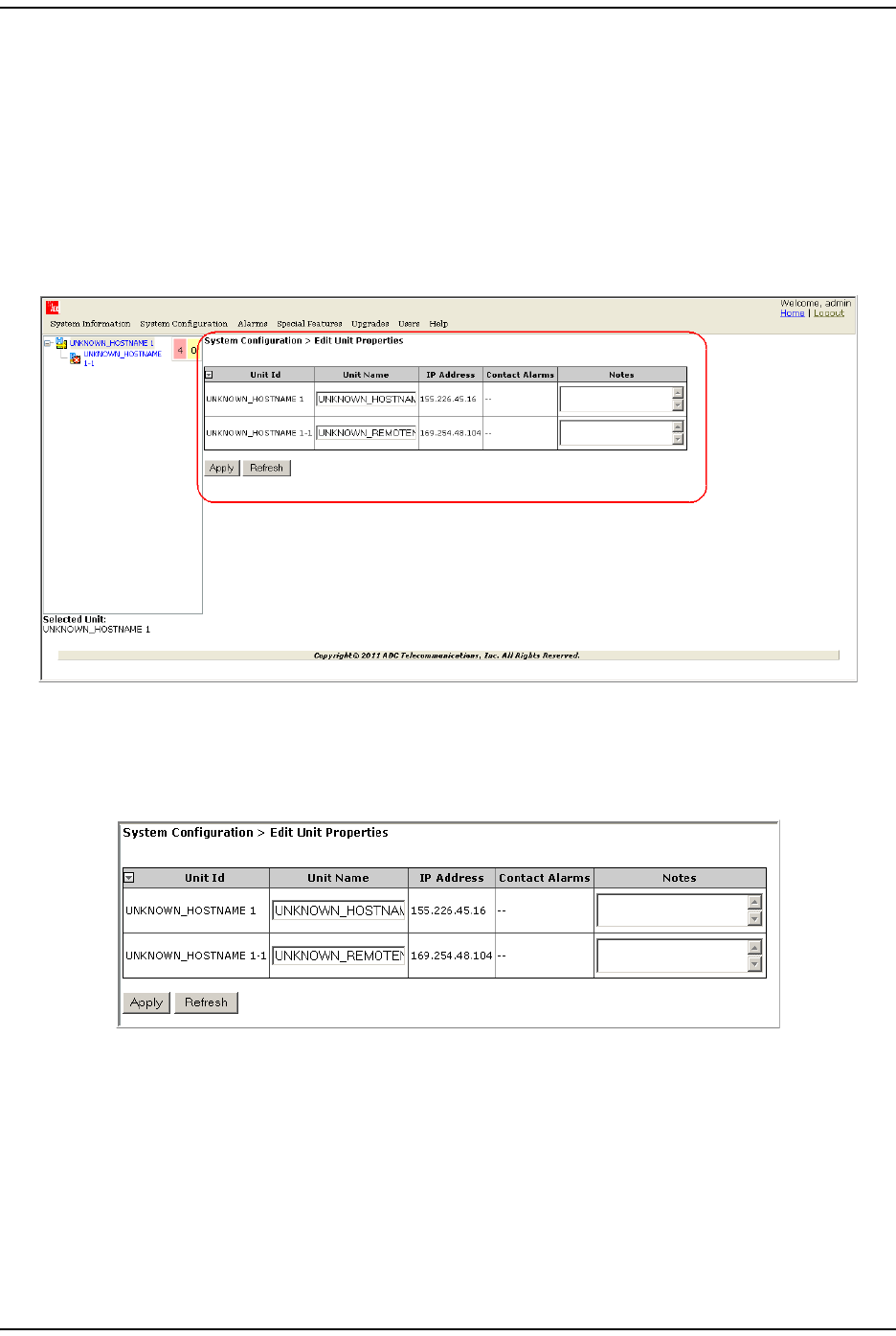
Document Graphics
This manual documents an EMS, the features of which display in a web browser
window, as described in “How to Use the EMS Graphical User Interface” on
page 40. To display the entire web browser would reduce the image size in this
document, which would reduce the document’s usability. The screen graphics will
therefore focus on the element of the web page under discussion. In most
instances, this will be the current view in the EMS View frame, which is encircled
in red in Figure 1.
Figure 1. EMS in Web Browser
For example, when discussing the Edit Unit Properties page shown in Figure 1, only
the Edit Unit Properties panel will be illustrated (see Figure 2).
Figure 2. Edit Unit Properties Panel

Preface
FlexWave Prism Element Management System 7.1 User Manual Page xiii
ADCP-77-177 • Issue 1 • July 2011 © 2011 ADC Telecommunications, Inc.
ABBREVIATIONS/ACRONYMS
This section defines abbreviations/acronyms used in this manual.
Abbreviations/Acronyms Definition
AC Alternating Current
BDA Bi-Directional Amplifier
BER Bit Error Rate
BTS Base Transceiver Station
COM Common
CWDM Coarse Wavelength Division Multiplexer
DART Digital/Analog Radio Transceiver
DAS Distributed Antenna System
db Decibels
dBm decibel measured in reference to milliwatts
DC Direct Current
EMS Element Management System
FLM Forward Link Monitoring
FWD Forward
GUI Graphical User Interface
Id Identification
IF Intermediate Frequency
LNA Low Noise Amplifier
LPA Linear Power Amplifier
MHz Megahertz
MMW Millimeter Wave
sMicroseconds
NC Normally Closed
NIC Network-Interface Connection
nm Nanometer
NO Normally Open
OSP Outside Plant
Pkt Packet
PLL Phase-Locked Loop
PRU Prism Remote Unit
RDI Remote DART Interface
REV Reverse
RF Radio Frequency
RLM Reverse Link Monitoring
RSI Remote SeRF Interface
RX Receive
SeRF Serialized RF
SFP Small Form-Factor Pluggable

Abbreviations/Acronyms
Page xiv FlexWave Prism Element Management System 7.1 User Manual
© 2011 ADC Telecommunications, Inc ADCP-77-177 • Issue 1 • July 2011
SNMP Simple Network Management Protocol
TX Transmit
UPS Uninterruptible Power Supply
URU URH Remote Unit
VLAN Virtual Local Area Network
VSWR Voltage Standing Wave Ratio
WDM Wavelength Division Multiplexer
Abbreviations/Acronyms Definition

FlexWave Prism Element Management System 7.1 User Manual Page 1
ADCP-77-177 • Issue 1 • July 2011 © 2011 ADC Telecommunications, Inc.
PART I
FLEXWAVE PRISM HARDWARE

Page 2 FlexWave Prism Element Management System 7.1 User Manual
© 2011 ADC Telecommunications, Inc ADCP-77-177 • Issue 1 • July 2011
Intentionally Blank Page

FlexWave Prism Element Management System 7.1 User Manual Page 3
ADCP-77-177 • Issue 1 • July 2011 ©2011 ADC Telecommunications, Inc.
PRISM SYSTEM OVERVIEW
Prism System Overview ...........................................................................................................4
Fiber Optic Transport..............................................................................................................10
Host Unit Overview ................................................................................................................11
Fan Module......................................................................................................................11
SeRF II Module ................................................................................................................12
SeRF II Module Ports...................................................................................................12
SeRF II Module LEDs ...................................................................................................13
Host System II Module......................................................................................................14
Host System II Module Ports and Connectors..................................................................14
Host System II Module LEDs.........................................................................................15
DC Power Module .............................................................................................................15
Prism Remote Units................................................................................................................16
PRU Ports and Connectors (Bottom of PRU)..........................................................................17
PRU Status LED (Bottom of PRU)........................................................................................18
PRU Components..............................................................................................................19
RF Module Capabilities and GUI Representation ....................................................................21
DART Modules .......................................................................................................................24
Host DARTs .....................................................................................................................26
Host DART Slots .........................................................................................................27
Host DART Connectors and LEDs...................................................................................28
Serialized RF (SeRF) Digital Protocol ...................................................................................29
Simulcast Groups .............................................................................................................30
Use of Multi Fibers............................................................................................................31
E911 Support...................................................................................................................32
Prism System Specifications ....................................................................................................33
This section provides a basic description of an ADC® FlexWave® Prism system.
Topics Page

Prism System Overview
Page 4 FlexWave Prism Element Management System 7.1 User Manual
© 2011 ADC Telecommunications, Inc ADCP-77-177 • Issue 1 • July 2011
PRISM SYSTEM OVERVIEW
ADC’s FlexWave® Prism is a compact radio head utilized for precision and macro
gap coverage, which supports up to four frequency bands, while delivering
high-performance coverage with end-to-end management. FlexWave Prism is
ideal for enhancing outdoor and indoor coverage in urban, suburban, canyons,
tunnels, campuses, stadiums and other public venues.
A Prism system offers the following features:
•ADC’s patented RF-over-fiber transport eliminates installation-dependent gain
or fiber length adjustments
•Improved manageability for installation and upgrades
•Smaller size to ease placement and zoning approvals
•4G readiness with Four Band remote, which is ideal for incorporating 2G and
3G services with needs of 4G technologies such as LTE
•The unique capability to support digital RF as well as baseband compatibility
into a single fiber pair and remote radiating point
•Support for millimeter wave backhaul
•With its unique use of wideband digital RF transport, FlexWave Prism delivers
reliable and consistent performance in all environments. Signals are not
affected by reflection, dispersion, or frequency attenuation over fiber.
FlexWave Prism delivers a reliable signal at every remote location.
The ADC FlexWave Prism family of products is a Distributed Antenna System
(DAS) that provides ADC’s patented technology—bidirectional transport of
digitized RF spectrum over fiber. The high-speed digitalization of a wideband
portion of spectrum allows for transport of RF signals over extended distances,
without the RF degradation that normally results when analog systems are
impacted by optical effects. The basic function of the FlexWave Prism platform is
to transport via fiber optic cable RF signals from a Base Transceiver Station (BTS)
to an antenna interface allowing communication to a mobile device. Multiple BTS
communication paths are allowed over a single Prism system.
A very basic Prism system consists of a Host Unit (Host) and a Prism Remote Unit
(PRU).
•The Host is a three rack unit high chassis with multiple cards that mounts in a
standard equipment rack.
•The PRU consists of multiple electronic and optical modules mounted in an
outdoor enclosure.
On an optional basis, the Prism system supports reverse path diversity. In
addition, various accessory items such as a passive Wavelength Division
Multiplexer (WDM) system and a Coarse Wavelength Division Multiplexer (CWDM)
system are available as accessories.
Control and monitoring functions are provided by the FlexWave Element
Management System (EMS).
Prism System Overview
FlexWave Prism Element Management System 7.1 User Manual Page 5
ADCP-77-177 • Issue 1 • July 2011 © 2011 ADC Telecommunications, Inc.
Examples of FlexWave Prism Systems are shown in Figure 1, Figure 2 on page 6,
and Figure 3 on page 7.
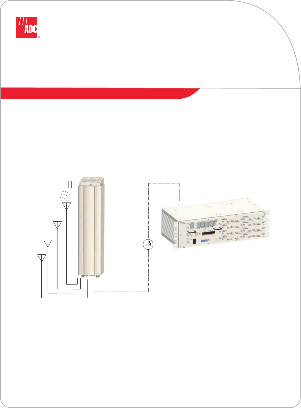
Figure 1. Three Bands to One PRU (No Simulcast)
Base Transceiver Stations
Frequency Band A
RF
Antenna
Frequency Band A
Antenna
Frequency Band B
Antenna
Frequency Band C
Host Unit
Tri-Band Remote Unit
Frequency Band B
RF
Frequency Band C
RF
Prism System Overview
Page 6 FlexWave Prism Element Management System 7.1 User Manual
© 2011 ADC Telecommunications, Inc ADCP-77-177 • Issue 1 • July 2011
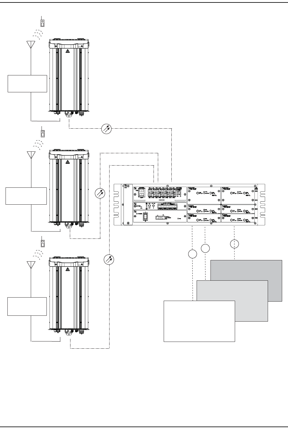
Figure 2. Multiple Point-to-Point Configuration
(One Band per PRU, Three Nodes)
Host Unit
RF
Base Transceiver Stations
Frequency Band A
Sector G
Frequency Band A
Sector B
Frequency Band A
Sector A
RF
RF
Antenna
Frequency Band A
Sector G
Antenna
Frequency Band A
Sector B
Antenna
Frequency Band A
Sector A
Three Single-Band Remotes
Prism System Overview
FlexWave Prism Element Management System 7.1 User Manual Page 7
ADCP-77-177 • Issue 1 • July 2011 © 2011 ADC Telecommunications, Inc.
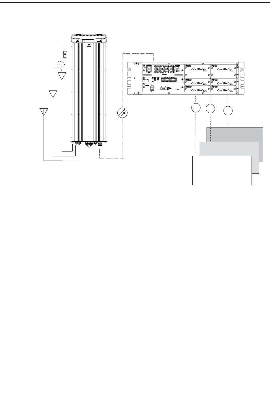
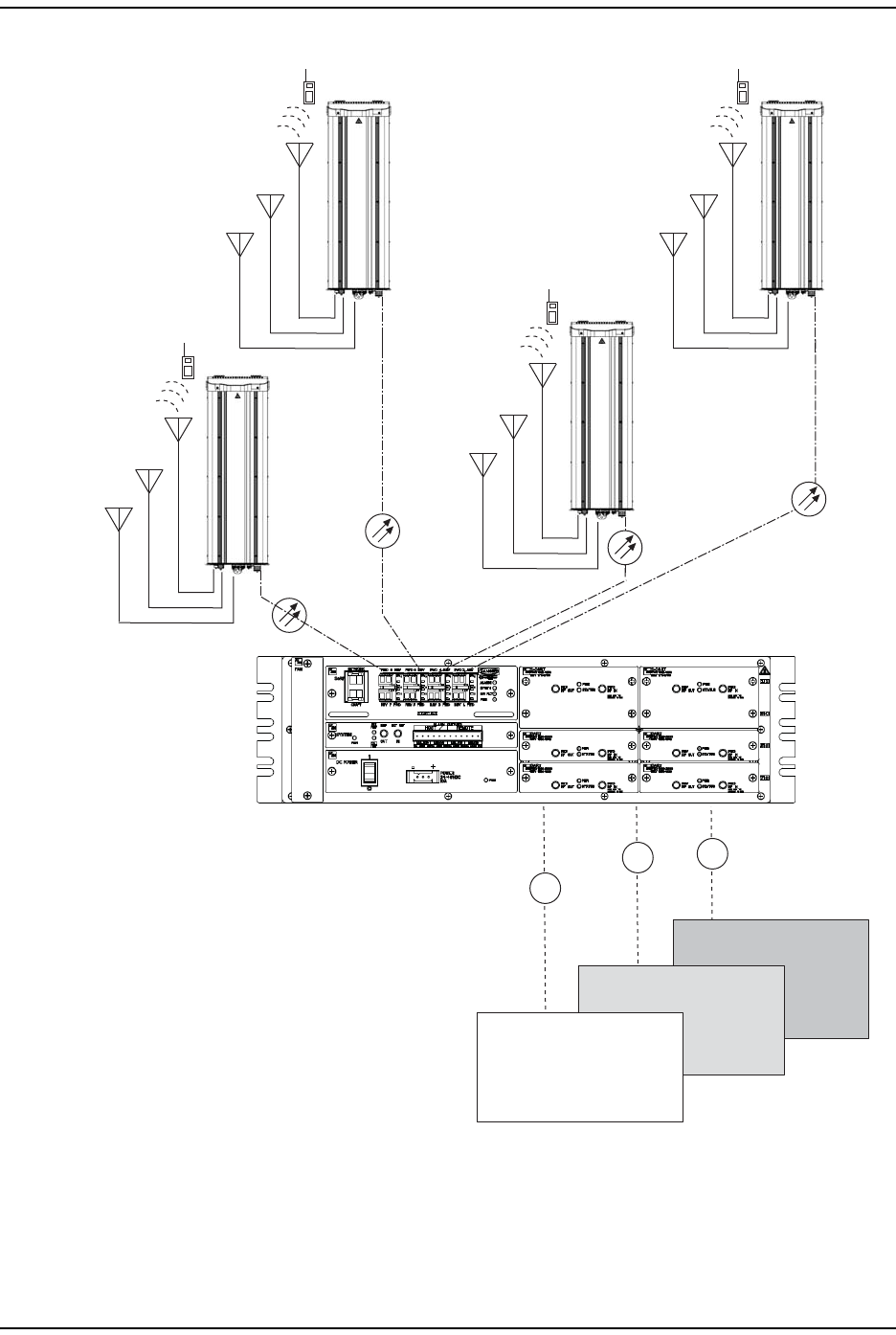
Figure 3. Four PRU Simulcast, Three Frequency Bands
Each link consists of a Host that provides the interface between the base station
RF ports and the optical fiber, and at least one Remote that provides the interface
between the optical fiber and the remote antenna.
RF
RF
Host Unit
Base Transceiver Stations
Frequency Band B
Frequency Band A
Four Tri-Band Remotes
Antenna Frequency
Band A
Antenna Frequency
Band B
Antenna Frequency
Band C
Antenna Frequency
Band A
Antenna Frequency
Band B
Antenna Frequency
Band C
Antenna Frequency
Band A
Antenna Frequency
Band B
Antenna Frequency
Band C
Antenna Frequency
Band A
Antenna Frequency
Band B
Antenna Frequency
Band C
RF
Frequency Band C
Prism System Overview
Page 8 FlexWave Prism Element Management System 7.1 User Manual
© 2011 ADC Telecommunications, Inc ADCP-77-177 • Issue 1 • July 2011
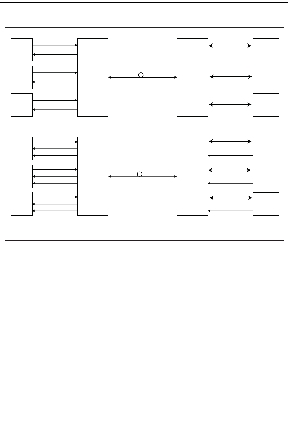
A block diagram of a point-to-point system is shown in Figure 4.
Figure 4. FlexWave Tri-Band Prism Block Diagram
FlexWave
Host
FWD RF IN
REV RF OUT
BTS 1
Antenna
Interface
BTS 1
BTS 2
BTS 3
Antenna
Interface
BTS 2
Antenna
Interface
BTS 3
NON-DIVERSITY
FWD RF IN
REV RF OUT
BTS 1
Antenna
Interface
BTS 1
BTS 2
BTS 3
Antenna
Interface
BTS 2
Antenna
Interface
BTS 3
DIVERSITY
REV DIV RF OUT REV DIV RF IN
REV DIV RF IN
REV DIV RF IN
FWD RF IN
REV RF OUT
REV DIV RF OUT
FWD RF IN
REV RF OUT
REV DIV RF OUT
FWD RF IN
REV RF OUT
FWD RF IN
REV RF OUT
FlexWave
Host
FlexWave
Remote
FlexWave
Remote
FWD RF OUT
REV RF IN
FWD RF OUT
REV RF IN
FWD RF OUT
REV RF IN
FWD RF OUT
REV RF IN
FWD RF OUT
REV RF IN
FWD RF OUT
REV RF IN
Prism System Overview
FlexWave Prism Element Management System 7.1 User Manual Page 9
ADCP-77-177 • Issue 1 • July 2011 © 2011 ADC Telecommunications, Inc.
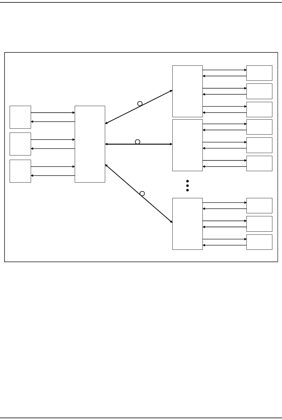
The basic function of FlexWave Prism simulcast (point-to-multipoint) is to
transport, via fiber optic cable, RF signals from a BTS to multiple antenna
interfaces allowing communication to a mobile device (see Figure 5). Up to 8
simulcast Remote Units are supported by each Host Unit.
Figure 5. System Block Diagram for Eight-Way Simulcast
FlexWave
Host
FWD RF IN
REV RF OUT
BTS 1
BTS 2
BTS 3
FWD RF IN
REV RF OUT
FWD RF IN
REV RF OUT
FlexWave
Remote 1
Antenna
Interface
BTS 1
FWD RF OUT
REV RF IN
FWD RF OUT
REV RF IN
FWD RF OUT
REV RF IN
FWD RF OUT
REV RF IN
FWD RF OUT
REV RF IN
FWD RF OUT
REV RF IN
FWD RF OUT
REV RF IN
FWD RF OUT
REV RF IN
FWD RF OUT
REV RF IN
FlexWave
Remote 2
FlexWave
Remote 8
Antenna
Interface
BTS 2
Antenna
Interface
BTS 3
Antenna
Interface
BTS 1
Antenna
Interface
BTS 2
Antenna
Interface
BTS 3
Antenna
Interface
BTS 1
Antenna
Interface
BTS 2
Antenna
Interface
BTS 8
Fiber Optic Transport
Page 10 FlexWave Prism Element Management System 7.1 User Manual
© 2011 ADC Telecommunications, Inc ADCP-77-177 • Issue 1 • July 2011
FIBER OPTIC TRANSPORT
In a FlexWave Prism system, each BTS provides the RF channel inputs and outputs
for a designated sector. Each Host may be interfaced with one or more Base
Transceiver Station (BTS).
On the forward path, the Host receives Analog RF signals from the BTS, digitizes
the designated RF bands, and then transports them over single-mode fiber to up
to 8 Remote Units. The Remote Unit(s) receives the digitized spectrum from the
Host and converts the spectrum back into an analog RF signal to be distributed via
an externally mounted antenna system.
On the reverse path, the Remote Unit digitizes the designated RF spectrum and
digitally transports it over single mode fiber or Millimeter Wave (MMW) to the
Host. The Host receives the digitized RF signals from the Remote Unit and converts
them back to Analog RF for the BTS.
In a typical Prism system the Host is connected to the Remote using two
single-mode optical fibers. One fiber is used to transport the forward path optical
signal and a second fiber is used to transport the reverse path optical signal.
Because the optical signal is digital, the input and output RF signal levels at the
Host or the Remote are not dependent on the level of the optical signal or the
length of the optical fiber. A diagram of the standard fiber optic transport system
for both a non-diversity and diversity system is shown in Figure 6.
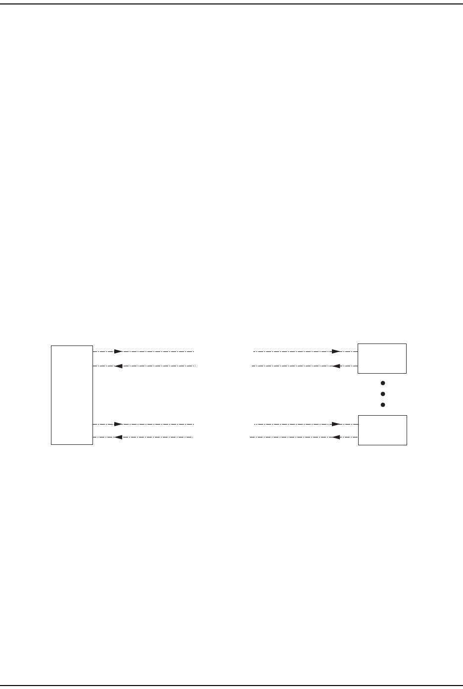
Figure 6. Standard Fiber Optic Transport Application
The maximum length of the optical links is dependent on the loss specifications of
the optical fiber and the losses imposed by the various connectors and splices. The
system provides an optical budget of 25 dB (typical) when used with 9/125
single-mode fiber. There must be at least 10 dB of optical loss to prevent
over-driving and possible damage to the optical receiver.
NOTE: The RF modulation used determines the maximum fiber length between the Host and
Remote units, which is dependent on how much delay that modulation type will handle.
77073-008
Remote
Unit
Forward Path
Reverse Path
Non-Diversity Fiber Optic Link
Forward Path
Diversity Fiber Optic Link
Reverse Path
And
Diversity Reverse Path
Host
Unit
Remote
Unit
Up To
Eight
Prism System Overview
FlexWave Prism Element Management System 7.1 User Manual Page 11
ADCP-77-177 • Issue 1 • July 2011 © 2011 ADC Telecommunications, Inc.
HOST UNIT OVERVIEW
The rack-mountable Host is typically located with the RF source—a Base
Transceiver Station (BTS). The Host is DC powered and supports up to eight BTS
interfaces through DART (Digital/Analog Radio Transceiver) cards. (For further
information on DART Modules, see “DART Modules” on page 24.)
The Host is designed for use within a non-condensing indoor environment, such
as inside a base-station shelter, Central Office, wiring closet, or a
controlled-environment cabinet. It is installed into a 19- or 23-inch, rack-mounted
chassis, that is 9-inches deep and can hold up to three units. All controls,
connectors, and indicators, except for the grounding point, are accessible on front
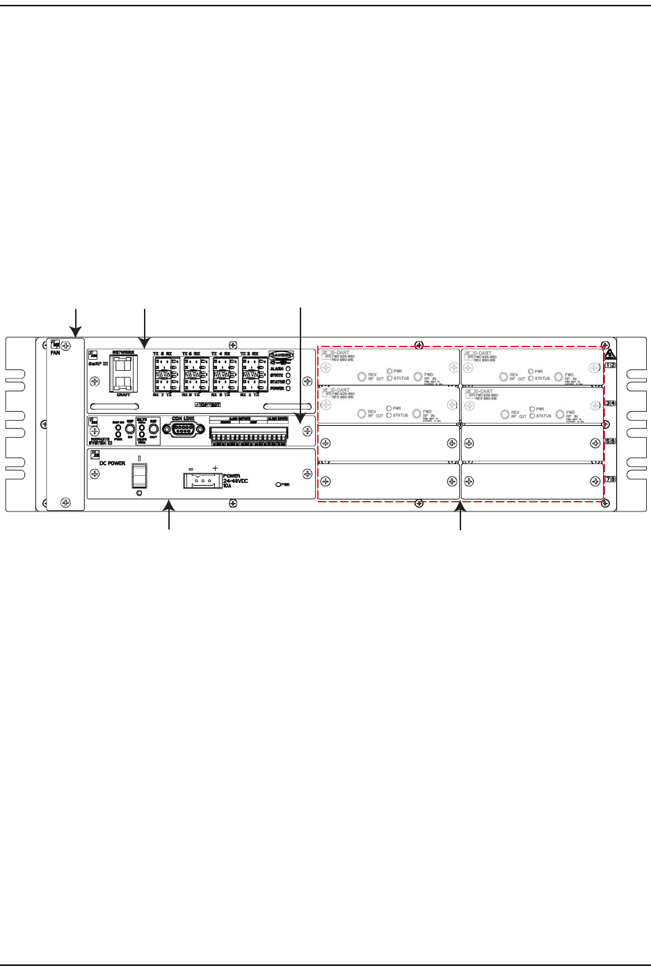
of the Host. Figure 7 shows the main elements of the Host.
Figure 7. Host Front Panel
NOTE: The Host comprises a Fan Assembly, a SeRF II Board Module, a Host System II Module,
and a DC Power Module. These modules are pre assembled in the Host chassis at the
factory. This document describes them as separate modules for reference only.
Fan Module
The Fan Module, mounted on the left side of the Host, continuously blows cool air
into the Host enclosure, and vents hot air out of the chassis on the right. An alarm
is generated if a high-temperature condition occurs. The Fan Module is field
replaceable (see the Prism Host Unit Installation Guide, ADCP-77-089).
Fan
Assembly
SeRF II
Module
System II
Board Module
DC Power
Module
Slots 1 - 8 for DART cards
(Slots 1 - 4 are occupied)
Host Unit Overview
Page 12 FlexWave Prism Element Management System 7.1 User Manual
© 2011 ADC Telecommunications, Inc ADCP-77-177 • Issue 1 • July 2011
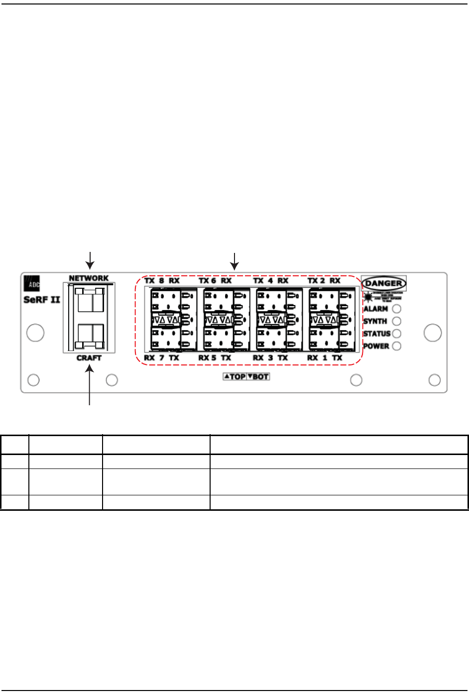
SeRF II Module
The SeRF II Module:
•manages communications and alarms
•receives digitized signals from the DART and sends the digitized RF bands to
the designated PRU
•receives digitized RF signals from the PRU and sends the digitized RF signal to
the DART for conversion from Digital RF to Analog RF for the BTS/BDA
•supports eight Small Form-factor Pluggable (SFP) optical transceivers
•provides two Ethernet interfaces.
SeRF II Module Ports
Ref # Component Device Function
1Network port RJ-45 jack (female) Networking access to an external DHCP server
2TX/RX Optical port
(1–8)
LC (flat-polished) connector
(single-mode)
Input/output connection points for Ports 1 through 8 Transmit (TX) and
Receive (RX) optical fiber pairs
3Craft port RJ-45 jack (female) Local Ethernet access to the Host
12
3
Prism System Overview
FlexWave Prism Element Management System 7.1 User Manual Page 13
ADCP-77-177 • Issue 1 • July 2011 © 2011 ADC Telecommunications, Inc.
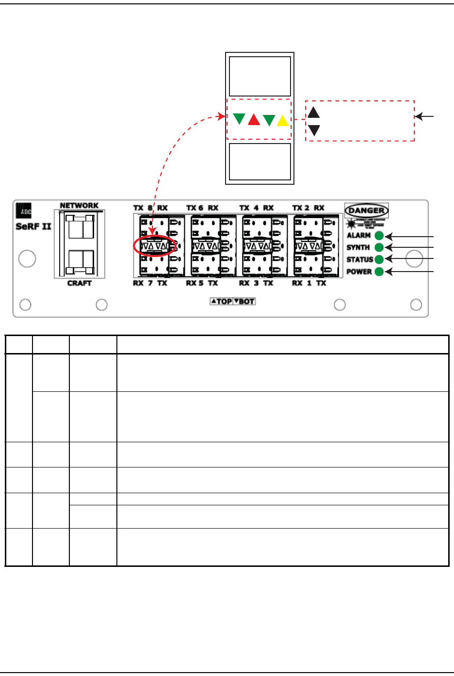
SeRF II Module LEDs
Ref # LED LED Color Description
1
SFP TX •OFF
• GREEN
•RED
• No Small Form-Factor Pluggable (SFP) present
• SFP is present and the FPGA internal Phase-Locked Loop (PLL) is locked
• SFP is present and the FPGA internal PLL is not locked
SFP RX •OFF
• GREEN
•AMBER
•RED
• No SFP present
• Receiver has locked and framed to the incoming signal
• Receiver has light, but is not locked to the incoming frequency or not framed
• Receiver has no light
2ALARM • GREEN • No major alarm is present in the system
• RED • Initial bootup sequence, or a major alarm is present in the system
3SYNTH • GREEN • Locked
• RED • Unlocked
4STATUS
• GREEN • No alarm for the SeRF II Module
• RED • Initial bootup sequence and should become GREEN within 1 minute; if RED after bootup, a
Major alarm exists for the SeRF II Module
5POWER
• GREEN • Power OK and operating properly
• RED • Power supply out of tolerance
• OFF • No power present
SFP8
Tx Rx
SFP7
Tx
Rx
LEDs for SFP in top port 1
2
3
4
5
LEDs for SFP in bottom port
Host Unit Overview
Page 14 FlexWave Prism Element Management System 7.1 User Manual
© 2011 ADC Telecommunications, Inc ADCP-77-177 • Issue 1 • July 2011
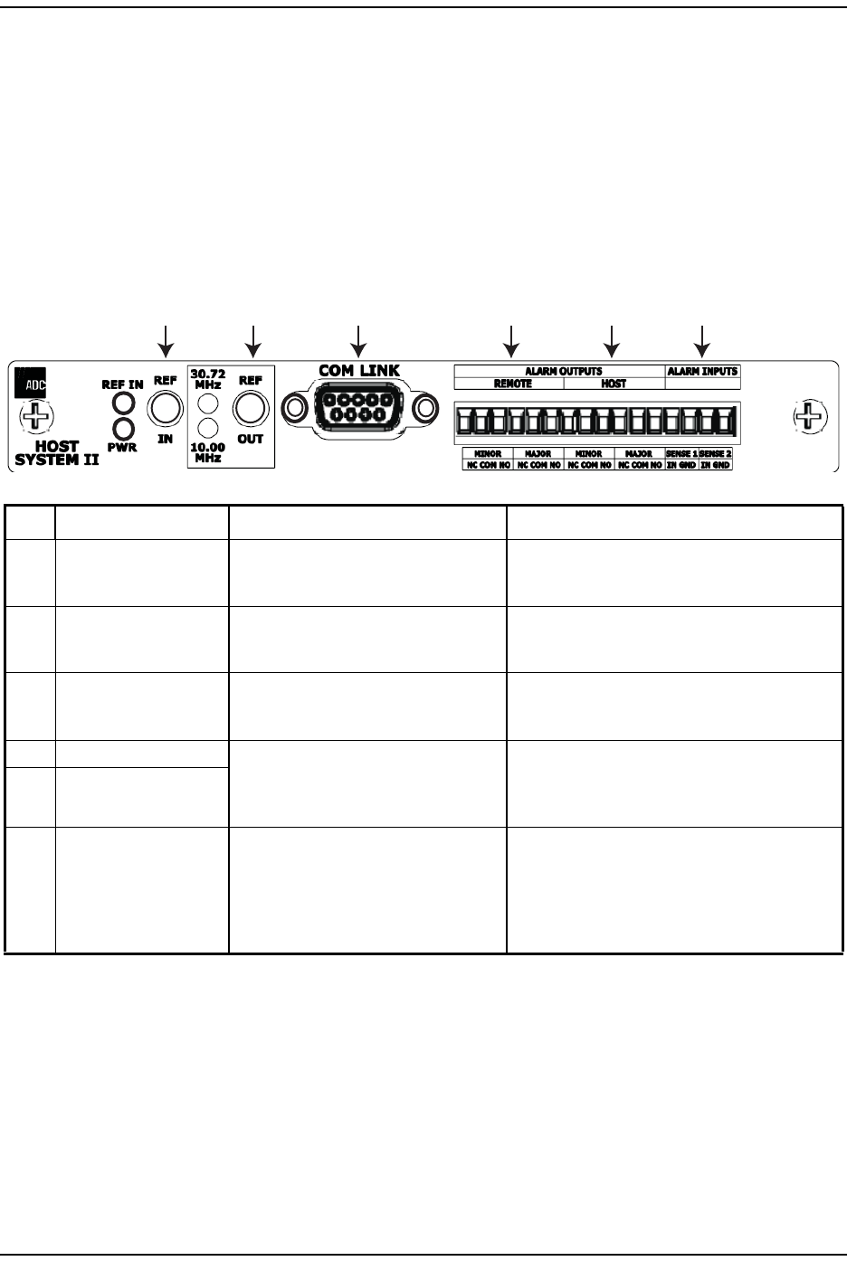
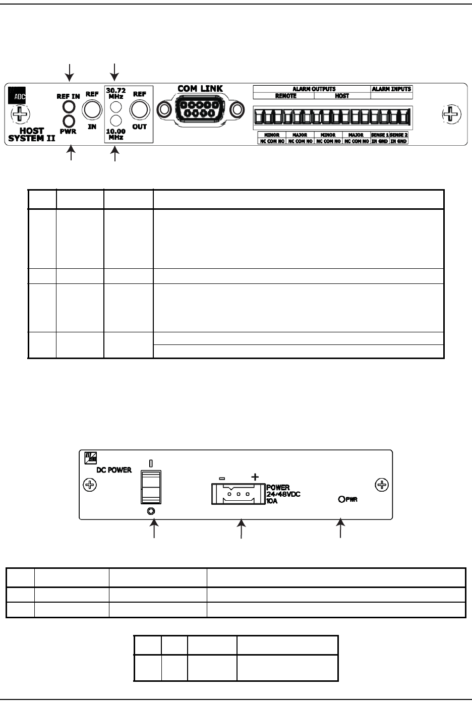
Host System II Module
The Host System II Module:
•provides output dry alarm contacts for reporting alarms to an external
management system
•can output the reference clock to a daisy-chained Host.
Host System II Module Ports and Connectors
Ref # Component Device Function
1REF IN connector QMA-Type female RF coaxial connector 10 MHz reference clock input that may be used to
synchronize between multiple Hosts in a
daisy-chain configuration.
2REF OUT connector QMA-Type female RF coaxial connector 10 MHz reference clock output that may be used to
synchronize between multiple Hosts in a
daisy-chain configuration.
3COM LINK connector DB9 female connector Not applicable to the Prism Host. The COM Link is
only used when the System II Board is configured
as a Remote System II Board.
4Alarm Outputs—PRU Twelve position terminal block.
Screw-type terminal connector
(14–26 AWG)
Connection points for a major and minor dry alarm
contacts. Includes normally closed (NC), common
(COM), and normally open (NO) wiring
connections.
5
Alarm Outputs—Host
6
Alarm Inputs
Two contact closure inputs Connection points for monitoring external devices,
which allows the Alarm connector to monitor the
output contact closures from an Uninterruptible
Power Supply (UPS) or a Bi-Directional Amplifier
(BDA). This feature is currently not supported by
Prism systems.
12 3 4 5 6
Prism System Overview
FlexWave Prism Element Management System 7.1 User Manual Page 15
ADCP-77-177 • Issue 1 • July 2011 © 2011 ADC Telecommunications, Inc.
Host System II Module LEDs
DC Power Module
The DC Power Module converts ±24 - ±48 VDC to the DC voltages used by the
Host modules.
Ref # LED LED Color Description
1REF IN
• Green • An external reference has been selected in the Prism Element Management
System GUI. Once this selection has been made in the GUI, the REF IN LED
is green, regardless of the presence of a signal on the REF IN connector.
• Off • No external reference has been selected in the Prism Element Management
System GUI.
230.72 MHz Off For this release, this LED will always be off in a Prism Host Unit.
310 MHz
• Green • The system is configured to output a 10MHz signal on the Ref Out connector.
(The input of an external 10MHz clock on the Ref In connector is indicated by
the REF In LED.)
• Off • External 10 MHz reference disabled.
4PWR • Green • Host System II board is receiving power.
• Off • Host System II board is not receiving power.
Ref # Component Device Function
1ON/OFF Switch Rocker switch Turns Host power on/off
2POWER connector Three position connector 10A connector for DC power wiring; FCC qualification meets 21-60 VDC
Ref # LED LED Color Description
3PWR • Green • DC Power Supply OK
• Red • DC Power Supply Fault
12
3
4
123
Prism Remote Units
Page 16 FlexWave Prism Element Management System 7.1 User Manual
© 2011 ADC Telecommunications, Inc ADCP-77-177 • Issue 1 • July 2011
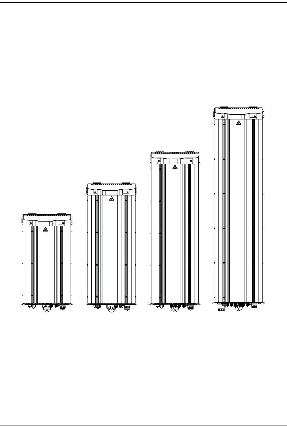
PRISM REMOTE UNITS
The Prism Remote Unit (PRU), shown in Figure 8, controls RF emissions, interfaces
with the FlexWave Host and performs the optical to electrical conversions for
transport to the antennas. The PRU is an IP-65 rated enclosure that houses the
electronic assemblies such as the RF Module Group, SeRF assembly and AC/DC
power supplies, and seals out dirt and moisture. The PRU uses fans located on the
top of each unit to cool the chassis. The antenna cable connectors, fiber
connectors, AC power connector, and the unit status indicator are located on the
bottom of the unit.
Figure 8. Prism Remote Units (PRUs)
The FlexWave Remote receives on the forward path the digitized spectrum from
the Host and converts the spectrum back into an RF signal to be distributed via an
externally mounted antenna system. On the reverse path, the Remote digitizes
the designated RF spectrum and digitally transports it over single-mode fiber or
Millimeter Wave (MMW) to the Host. The PRU also provides RF interface (antenna
port) for the antennas, and accepts AC power input.
Single-Band
Remote
Dual-Band
Remote
Tri-Band
Remote
Quad-Band
Remote
77152-007
Prism System Overview
FlexWave Prism Element Management System 7.1 User Manual Page 17
ADCP-77-177 • Issue 1 • July 2011 © 2011 ADC Telecommunications, Inc.
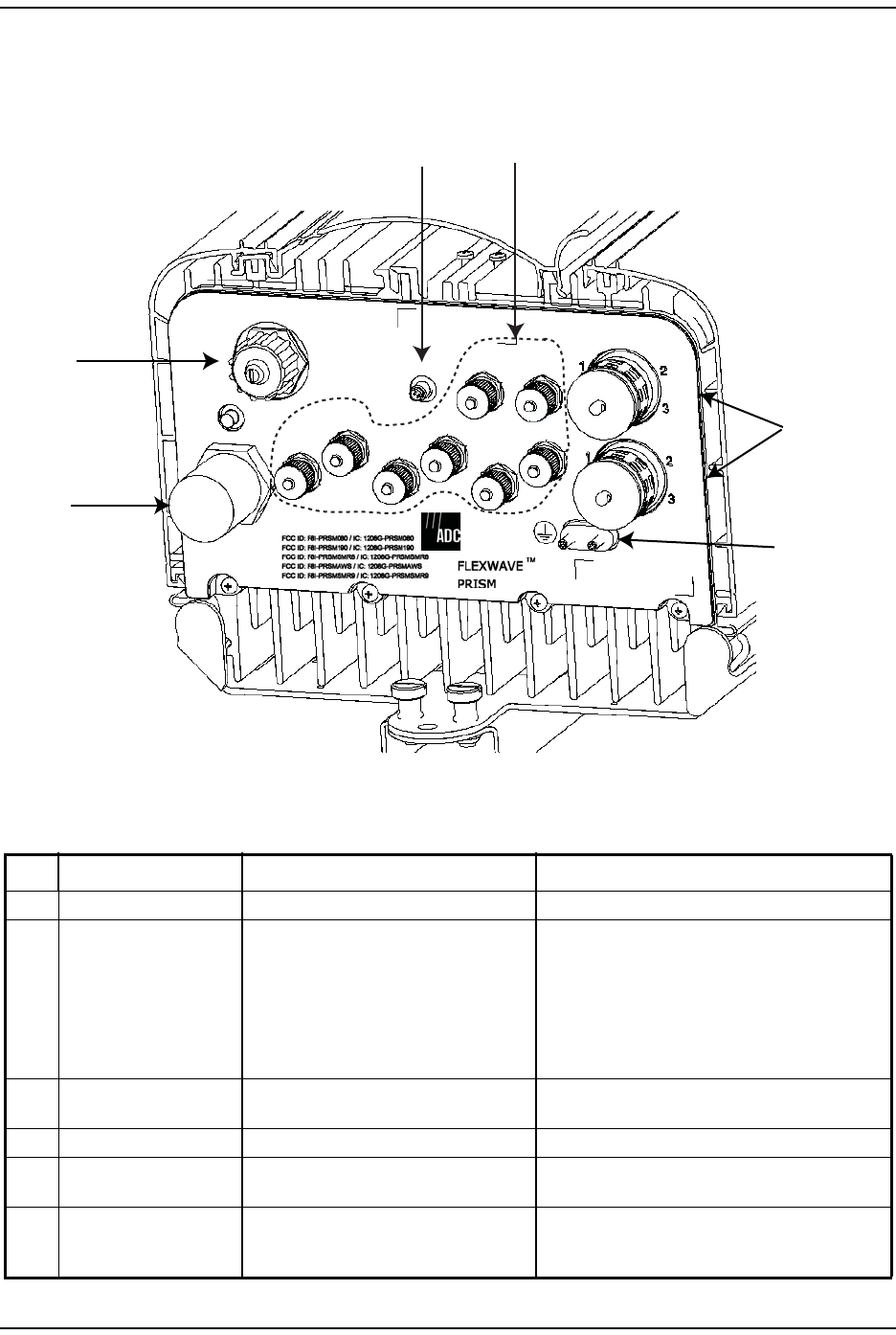
PRU Ports and Connectors (Bottom of PRU)
Ref # Component Device Function
1Aux Connector Four contact closure inputs Connection points for external alarm inputs.
2Antenna Connectors Eight 50 N-Type (female) connectors • Connection points between the PRU and up to
four antennas are labeled as Mod X TXO/RXO
(where the first X can be A, B, C, or D).
• Connection points between the PRU and
Diversity receive for RF power from the antenna
are labeled as Mod X RX1 (where the first X can
be A, B, C, or D).
3Fiber Connectors ProAx connectors that provide four BX5
connectors
Connection points between the PRU and the
Outside Plant (OSP) box.
4Dual-Ground Connector Ground connector Grounds the PRU.
5AC Power Port Sealed 3-pin port Connection point between the PRU and an AC
power junction box.
6
Network Connector Port
RJ-45 female connector IP servicing between the Host and PRU(s); allows
communications with the internal processor and
transfer of service data to the optical protocol.
NETWORK
AUX.
MOD A
RX1
MOD A
TX0/RX0
FIBER 1
FIBER 2
MOD B
TX0/RX0
MOD B
RX1
MOD C
TX0/RX0
MOD D
TX0/RX0
MOD C
RX1
MOD D
RX1
POWER
100-240 VAC
50-60 Hz
16 AMPS
Bottom of a PRU
6
5
3
4
12
Prism Remote Units
Page 18 FlexWave Prism Element Management System 7.1 User Manual
© 2011 ADC Telecommunications, Inc ADCP-77-177 • Issue 1 • July 2011
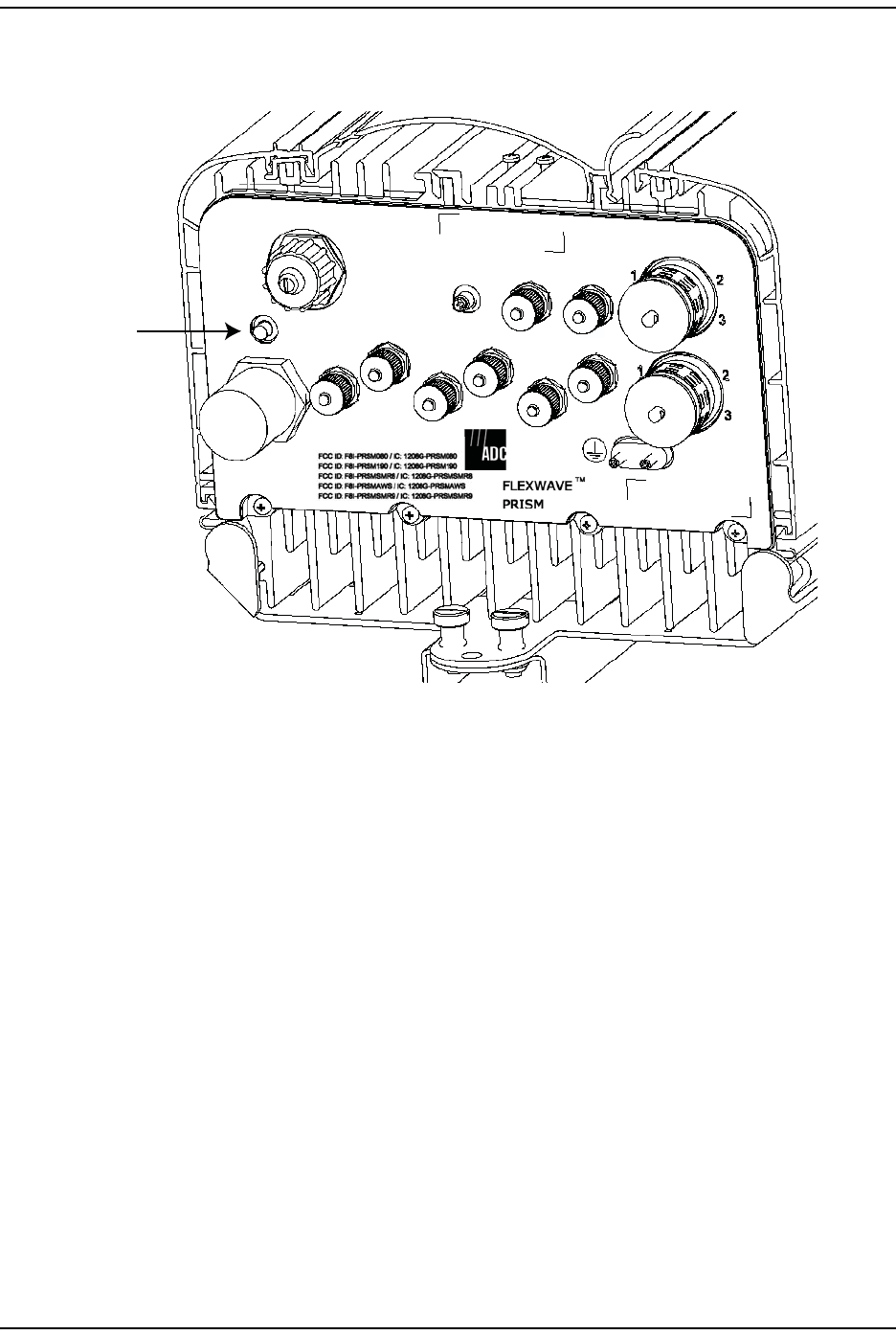
PRU Status LED (Bottom of PRU)
The PRU has a single red Status LED that is located on the bottom of the chassis.
At system startup, the PRU Status LED is red to indicate that the PRU is powering
up and that the SeRF processor does not yet control the PRU.
After start up, if the PRU Status LED is red, it indicates the presence of major
alarm(s) on the PRU. The PRU Status LED stays red until all the major alarm
conditions that exist on the PRU clear. (For information on alarms that pertain to
the PRU, see “Troubleshooting Alarms” on page 185.)
NETWORK
AUX.
MOD A
RX1
MOD A
TX0/RX0
FIBER 1
FIBER 2
MOD B
TX0/RX0
MOD B
RX1
MOD C
TX0/RX0
MOD D
TX0/RX0
MOD C
RX1
MOD D
RX1
POWER
100-240 VAC
50-60 Hz
16 AMPS
Status LED—Bottom of a PRU
Staus LED

Prism System Overview
FlexWave Prism Element Management System 7.1 User Manual Page 19
ADCP-77-177 • Issue 1 • July 2011 © 2011 ADC Telecommunications, Inc.
PRU Components
The PRU chassis is an outdoor-rated enclosure that comprises the following
components:
•Power Supplies
•SeRF Module
•Fans
•Interface connections as described in “PRU Ports and Connectors (Bottom of
PRU)” on page 17
•External Status LED (see “PRU Status LED (Bottom of PRU)” on page 18)
•Remote (AC) power and RF Module (DC) power switches
PRUs ship with specified RF Modules pre-installed. The Prism RF Modules
comprise:
•DARTs
•Linear Power Amplifier (LPA)
•Duplexer with one or two Low Noise Amplifiers (LNAs) and a Power Detector
(PD)
•Remote DART Interface (RDI) Module
For further information on the RF Modules, see “RF Module Capabilities and GUI
Representation” on page 21.
Prism Remote Units
Page 20 FlexWave Prism Element Management System 7.1 User Manual
© 2011 ADC Telecommunications, Inc ADCP-77-177 • Issue 1 • July 2011
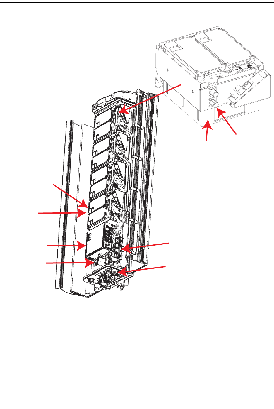
Figure 9 shows components within the Remote Unit chassis.
Figure 9. Prism Remote Unit (PRU) Components
SeRF Module
AC Power switch
Linear
Power
Amplifier
Cable connectors and Status LED
DART card
(one or two on
each RF Module)
Remote DART Interface (RDI)
(one on each RF Module)
Duplexer
DC Power switches
for RF Modules
RF Module
(one of four in this
Quad-Band Prism)
77072-009

Prism System Overview
FlexWave Prism Element Management System 7.1 User Manual Page 21
ADCP-77-177 • Issue 1 • July 2011 © 2011 ADC Telecommunications, Inc.
RF Module Capabilities and GUI Representation
A PRU comprises from one to four RF Module slots. Each RF Module can comprise
any of the following DART combinations:
•one Classic DART or one Single SuperDART
•two Classic DARTs
•two Single SuperDARTs
•one Dual SuperDART.
A PRU can therefore comprise up to eight single-slot DARTS or up to four Dual
SuperDARTs, dependent on the Remote chassis size and the number of RF
Modules installed. To link the Remote Unit DARTs to the DARTs in a Host Unit, the
DARTs must be the same type (such as, PCS to PCS).
NOTE: PRU RF Modules are not field serviceable. To replace a DART within a PRU, you must
replace the RF Module.
Prism Remote Units
Page 22 FlexWave Prism Element Management System 7.1 User Manual
© 2011 ADC Telecommunications, Inc ADCP-77-177 • Issue 1 • July 2011
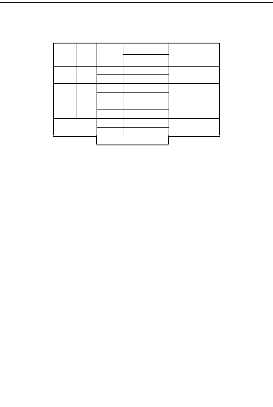
Table 1 and Figure 10 on page 23 describe how the EMS references the RF group
assignments and corresponding components of each RF Module.
NOTE: In a dual-LPA system, the Configure Remote Forward Gain page shows two values for the
LPA status, one for each LPA. Changing the LPA Mode or resetting the LPA applies to both
LPAs at the same time. For further information on setting the LPA Mode, see “Configure
Remote Forward Gain” on page 91. For further information on resetting an LPA, see
“Resetting an LPA” on page 165.
Table 1. Remote RF Group Assignments (from Top/Down)
Physical
RF Slot
RF
Group
DART
Number
LNA Number LPA
Number
Power
Detector
Number
Primary Diversity
D D 8 8 4 4
7 7
C C 6 6 3 3
5 5
B B 4 4 2 2
3 3
A A 2 2 1 1
1 1
SeRF Board
Prism System Overview
FlexWave Prism Element Management System 7.1 User Manual Page 23
ADCP-77-177 • Issue 1 • July 2011 © 2011 ADC Telecommunications, Inc.
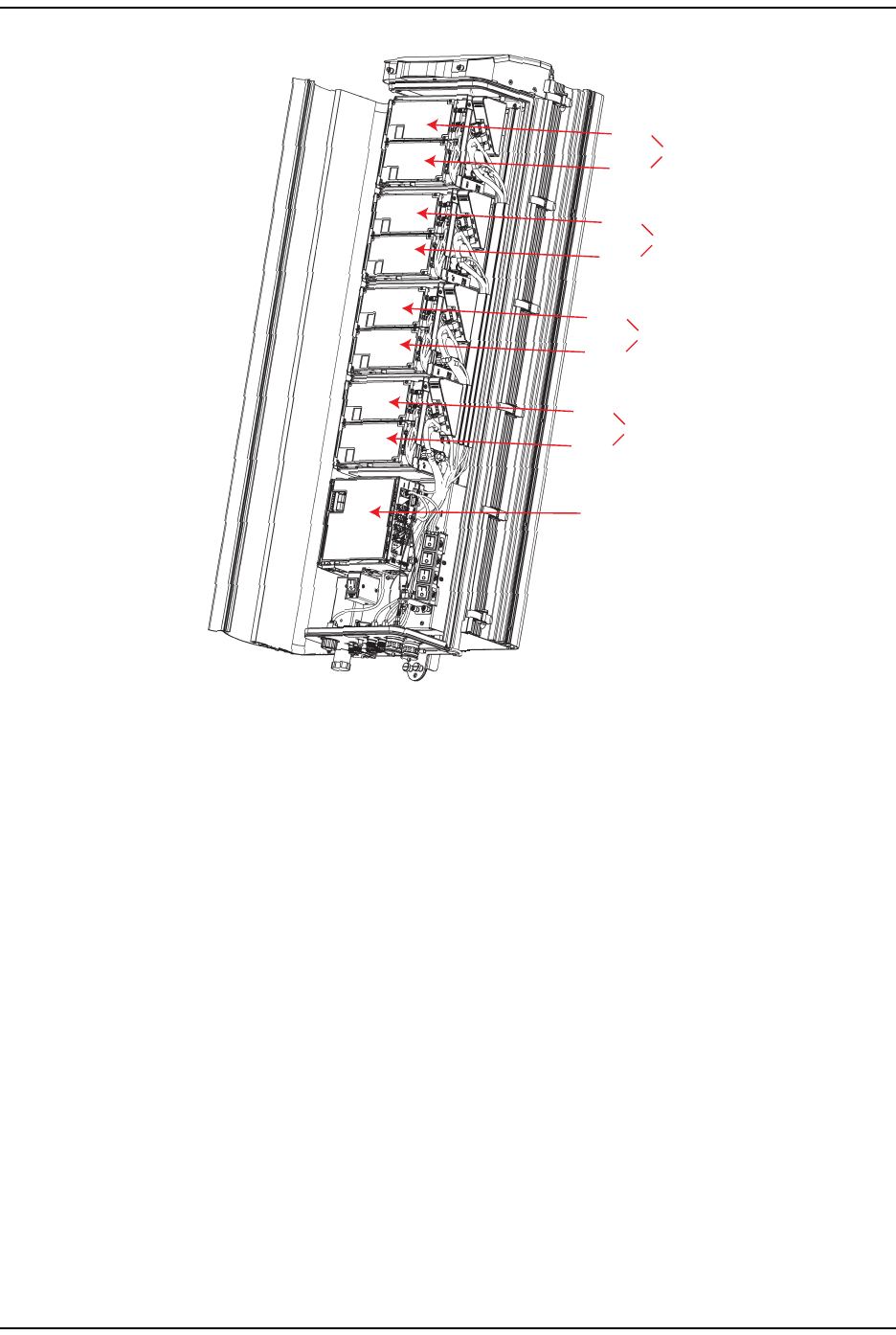
Figure 10. DART RF Groups in a Prism Remote Unit
SeRF Module
77152-010
DART 7
DART 8
Group D
DART 5
DART 6
Group C
DART 3
DART 4
Group B
DART 1
DART 2
Group A

DART Modules
Page 24 FlexWave Prism Element Management System 7.1 User Manual
© 2011 ADC Telecommunications, Inc ADCP-77-177 • Issue 1 • July 2011
DART MODULES
DART Modules:
•amplify, down-convert, filter and digitize the incoming RF signal
•convert incoming digital signal from the SeRF to analog, filter, amplify and
up-convert the frequency from Intermediate Frequency (IF) to RF
•provide a bi-directional interface between RF and the SeRF board (via FPGA,
D/A converter, and A/D converter)
•provide uplink gain
•support Simplex RF interfacing to/from the BTS
•perform adjustable delay processing.
Prism supports the following types of DART Modules:
•Classic DARTs are 6-timeslot DARTs that support up to 35 MHz contiguous
bandwidth (see Table 2).
•Single SuperDARTs are 6-timeslot DARTs that support two non-contiguous
bands in the entire frequency range of the DART, but cannot exceed 35 MHz
total RF bandwidth (see Table 3 on page 25).
•Single SuperDARTs that can support 70/75 MHz bandwidth in positions 1 or 3
when installed in a Host Unit II that has both a SeRF II Module and a Backplane
II chassis installed. (See Table 4 on page 25.)
•Dual SuperDARTs are 12-timeslot DARTs that support up to 70/75MHz with two
non-contiguous bands (see Table 4 on page 25).
NOTE: Industry Canada PCS 20 dB nominal bandwidth is less than 61.5 MHz.
NOTE: Industry Canada AWS 20 dB nominal bandwidth is less than 47.2 MHz
Table 2. Single-Slot Classic DARTs
DART Name Maximum
Bandwidth
(MHz)
Number of
Fiber Slots
800 APAC iDEN Classic 19 3
800 SMR Classic 18 3
850 Classic 25 4
900 SMR Classic 5 1

Prism System Overview
FlexWave Prism Element Management System 7.1 User Manual Page 25
ADCP-77-177 • Issue 1 • July 2011 © 2011 ADC Telecommunications, Inc.
For further information on DART Modules, see also “Host DARTs” on page 26 and
“RF Module Capabilities and GUI Representation” on page 21 (Remote RF Modules
contain Remote DARTs).
Table 3. Single-Slot SuperDARTs (1)
DART Name Maximum
Frequency
Span (MHz)
Maximum
Bandwidth
(MHz)
Maximum
Fiber Slots
1800 SGL SuperDART 75 39 6
1900 PCS SGL SuperDART 70 39 6
2100 SGL AWS SuperDART 45 39 6
2100 SGL UMTS SuperDART 60 39 6
700 LowerABC SGL SuperDART 18 3
700 UpperC SGL SuperDART 10 2
900 EGSM SGL SuperDART 35 6
(1) When using a Host Unit II with both the SeRF II and System Board II
modules, the bandwidths and fiber slots shown are only available in Host
DART Slots 1 and 3 for Single-Slot SuperDARTs.
Table 4. Dual-Slot SuperDARTs
DART Name Maximum
Bandwidth
(MHz)
Number of
Fiber Slots
1800 DL SuperDART 75 12
1900 PCS DL SuperDART 70 12
2100 DL AWS SuperDART 45 8
2100 DL UMTS SuperDART 60 12
DART Modules
Page 26 FlexWave Prism Element Management System 7.1 User Manual
© 2011 ADC Telecommunications, Inc ADCP-77-177 • Issue 1 • July 2011
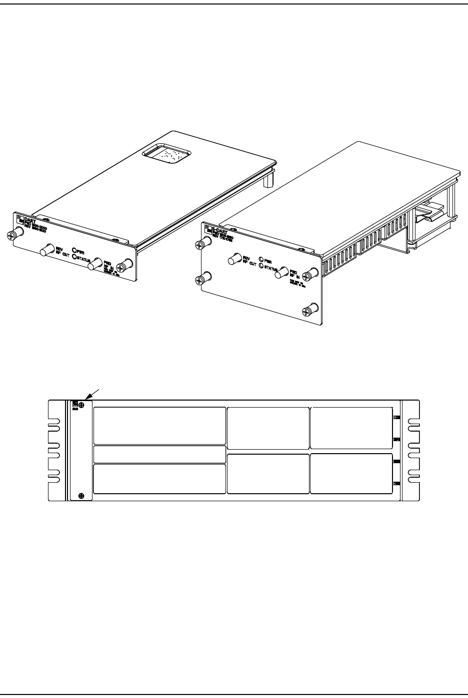
Host DARTs
The Host can support up to eight Classic DARTS and/or Single SuperDARTs or up
to four Dual SuperDARTs. Figure 11 provides generic representations of Classic
DARTS or Single SuperDARTs and Dual SuperDARTs.
Figure 11. DART Modules
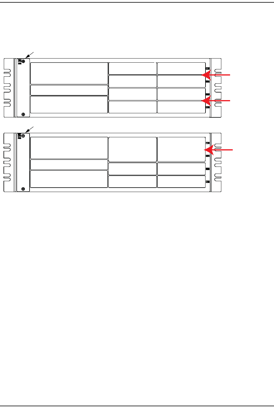
Figure 12 shows a Host that is fully loaded with Dual SuperDART Modules.
Figure 12. Host with Dual SuperDARTs
Generic representation of a
Classic DART or Single SuperDART
Generic representation of a
Dual SuperDART
77073-076
SeRF Card
System Card
Power Supply
Fan Assembly
Dual SuperDART
in Slots 1 and 3
Dual SuperDART
in Slots 2 And 4
Dual SuperDART
in Slots 5 And 7
Dual SuperDART
in Slots 6 And 8
77073-078
Prism System Overview
FlexWave Prism Element Management System 7.1 User Manual Page 27
ADCP-77-177 • Issue 1 • July 2011 © 2011 ADC Telecommunications, Inc.
Host DART Slots
Figure 13 shows the possible slot assignments for Single and Dual SuperDARTs,
and where slot-divider bars are located.
Figure 13. DART Slot Assignments in Host Chassis
Possible slot assignments for Single and Dual SuperDARTs are listed below.
•A Classic DART or Single SuperDART can be installed in each of the eight slots
in the Host.
•Single-Slot SuperDARTs plugged into slots 1 or 3 of a Host that has both a SeRF
II Module and a Backplane II chassis installed can pass 12 fiber slots like a
dual-slot SuperDART.
•Dual SuperDARTs require that slot divider bars be removed as their size
requires two-slot combinations, which are available in the following vertical
groupings:
–Slots 1 and 3
–Slots 2 and 4
–Slots 5 and 7
–Slots 6 and 8.
•Dual SuperDARTs cannot occupy horizontal slot combinations:
–Slots 3 and 5
–Slots 4 and 6.
•Any combination of DARTs may be installed.
SeRF Card
System Card
Power Supply
Single-Slot DART
in Slot 1
Single-Slot DART
in Slot 3
Single-Slot DART
in Slot 2
Single-Slot DART
in Slot 4
Single-Slot DART
in Slot 7
Single-Slot DART
in Slot 5
Single-Slot DART
in Slot 8
Single-Slot DART
in Slot 6
Fan Assembly
Divider bars between
Slots 1 and 3
and Slots 2 and 4
Divider bars between
Slots 5 and 7
and Slots 6 and 8
SeRF Card
System Card
Power Supply
Fan Assembly
77073-077
Dual-Slot DART
in Slots 1 and 3
Dual-Slot DART
in Slots 2 and 4
Single-Slot DART
in Slot 7
Single-Slot DART
in Slot 5
Single-Slot DART
in Slot 8
Single-Slot DART
in Slot 6
Divider bars between
Slots 1 and 3 and
Slots 2 and 4 removed
to accommodate
Dual-Slot DARTs
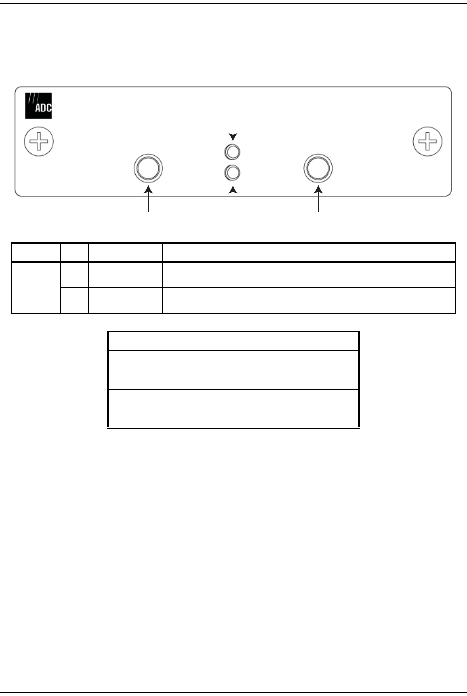
DART Modules
Page 28 FlexWave Prism Element Management System 7.1 User Manual
© 2011 ADC Telecommunications, Inc ADCP-77-177 • Issue 1 • July 2011
Host DART Connectors and LEDs
Only RF DART Modules can be installed in the Host Unit.
DART Type Ref # Component Device Function
Host RF 2FWD RF IN QMA-Type female RF
coaxial connector
Input connection point for the forward path RF coaxial
cable to the BTS
4REV RF OUT QMA-Type female RF
coaxial connector
Output connection point for the reverse path RF
coaxial cable to the BTS
Ref # LED LED Color Description
1PWR • Green • Card is powered.
• Red • Problem with onboard power
• Off • No power present at card.
3STATUS •Green •OK
•Red •Major Alarm
• Yellow • Automatic Level Control active
1
4 3 2
Host RF DART
REV
RF OUT
FWD
RF IN
PWR
STATUS
S-DART
FWD 925-960
REV 880-915
FWD NOT TO
EXCEED +5 dBm

Prism System Overview
FlexWave Prism Element Management System 7.1 User Manual Page 29
ADCP-77-177 • Issue 1 • July 2011 © 2011 ADC Telecommunications, Inc.
Serialized RF (SeRF) Digital Protocol
The SeRF (Serialized RF) digital protocol consists of digitized RF, Fast Ethernet,
and Host to Remote communication and management. The protocol provides you
with full access to the 100BASE-T (Ethernet) connection between the Host and
each Remote, and the ability to provision the RF spectrum of the DARTs. The
digitized RF portion of the SeRF protocol is divided into 12 timeslots, with each
timeslot representing roughly 5 MHz of digitized RF spectrum. Utilizing the full 12
timeslots yields between 60 and 75 MHz of total digitized RF on each SeRF Small
Form-Factor Pluggable (SFP) laser connection (single fiber pair).
The available RF bandwidth per timeslot is shown in Table 5.
For example, a user who wishes to transport PCS A block, Cellular A, and AWS B
block, the system would require the following:
PCS A 15MHz, 3 timeslots
Cellular A 10MHz, 2 timeslots
AWS B 10MHz, 2 timeslots
__________________________
Total = 35MHz, 7 timeslots
Each fiber pair supports 12 timeslots, or up to 75 MHz of bandwidth. Table 5 shows
the maximum bandwidth versus the number of timeslots.
If more than 70 MHz is required per Remote, up to three additional fiber pairs can
be brought to the Remote to get up to up to 280MHz per Remote (or 300MHz if all
four are GSM-1800).
Table 5. Available RF Bandwidth
Number of
Timeslots
Maximum Contiguous
RF Bandwidth (MHz)
Classic
DARTs
Single and Dual
SuperDARTs
1 5 6
212.5 12
3 20 18
4 25 25
6 35 39
8--- 45
12 --- 60-75

DART Modules
Page 30 FlexWave Prism Element Management System 7.1 User Manual
© 2011 ADC Telecommunications, Inc ADCP-77-177 • Issue 1 • July 2011
Simulcast Groups
Simulcast combining occurs when more than one Remote DART is linked to the
same Host DART. The gains of the reverse signals are reduced before summation
to prevent over-flow when the digital signals are added together. This simulcast
gain reduction is accomplished as a function of the number of Remote DARTs
linked to the Host DART (N) and the selected Reverse Gain Mode:
•Mode 1 (Noise Floor Matching)—uses an algorithm that normalizes the noise floor of
all Remote Units.
•Mode 2 (Legacy Prism/URH)—reduces the gain by 20*log10(N).
•Mode 1 (Noise Floor Matching) uses an algorithm that normalizes the noise floor
of all Remote Units.
•Mode 2 (Legacy Prism/URH)—reduces the gain by 20*log10(N).
Table 6 illustrates gain reduction for Mode 1 and Mode 2.
Simulcast groups are restricted to using the same timeslots on the fibers to each
Remote. For example, if the first link established in a simulcast group is using
timeslots 1-3 on a fiber for the PCS A passband, timeslots 1-3 must be used for
that passband on each of the other Remotes in the simulcast group. If timeslots
1-3 are not available on a Remote's fiber, the Remote cannot be added to the
simulcast group.
To minimize timeslot conflicts, simulcast groups should be configured before other
passbands. If a conflict occurs while attempting to link a DART, an error message
displays indicating that the DART linking failed. The DART using the conflicting
timeslots must be unlinked to allow the DART in the simulcast group to be linked.
Table 6. Reverse Gain Mode and Gain Reduction
# Remote
DARTs
Reduction (dB)
Mode 1 Mode 2
1 0 0
23.0 6.0
34.7 9.5
46.0 12.0
57.0 14.0
67.8 15.6
78.3 16.9
89.0 18.0

Prism System Overview
FlexWave Prism Element Management System 7.1 User Manual Page 31
ADCP-77-177 • Issue 1 • July 2011 © 2011 ADC Telecommunications, Inc.
Use of Multi Fibers
The EMS provides the ability to install “multi fibers” between a Host and Remote.
This means that, in addition to the minimum single fiber pair (RX and TX) in the
Host to Remote connection, one or more additional fiber pairs are installed. This
is done to increase the bandwidth or number of timeslots between the Host and
Remote.
Each fiber pair can handle approximately 75 MHz of RF bandwidth and each fiber
is capable of supporting 12 timeslots, as described in “DART Modules” on page 24.
When a Host DART is linked to a Remote DART in a multi-fibers configuration, the
EMS uses the first fiber (in numerical order) on which the required number of
timeslots is available for the passband being linked. The EMS will not divide up the
timeslots between two fibers. So, for example, if the passband requires eight
timeslots, and only six timeslots are available on the first fiber, the EMS will bypass
the first fiber and assign all eight timeslots to the second fiber, leaving four
timeslots unused on the second fiber.
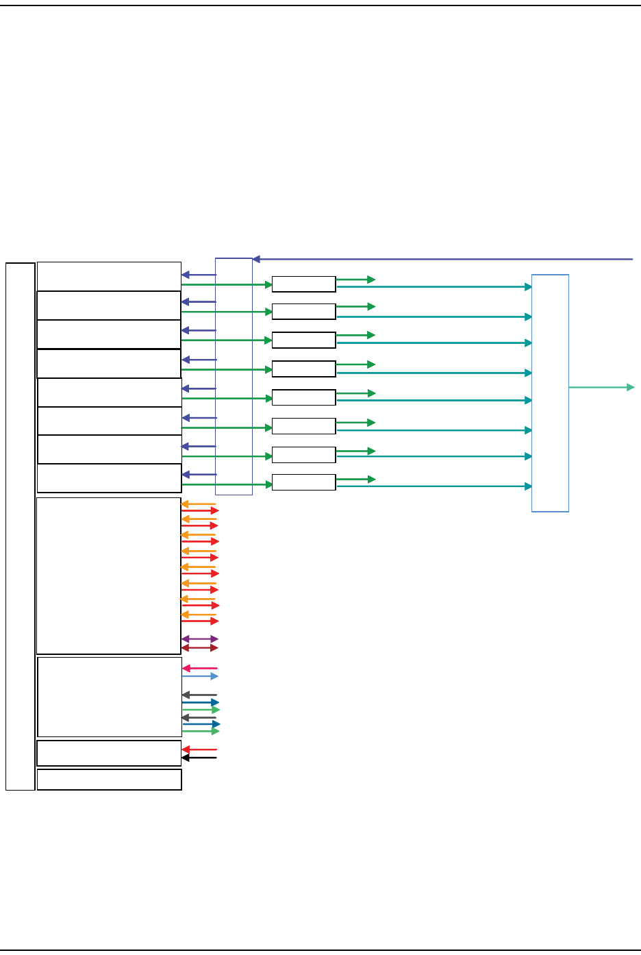
DART Modules
Page 32 FlexWave Prism Element Management System 7.1 User Manual
© 2011 ADC Telecommunications, Inc ADCP-77-177 • Issue 1 • July 2011
E911 Support
The DART type determines the maximum number of links, where there can be up
up to 8 Classic DARTs or Single SuperDARTs that support 35MHz each, or up to 4
Dual SuperDARTs that support up to 75MHz each.
E911 support may be achieved by using a configuration similar to the one shown
in Figure 14. Remote simulcasting in this configuration requires analog splitting
and combining to and from the individual Host DARTs. External analog
splitting/combining ensures that the E911 system receives uplink signals from
each Remote location before they are combined with uplink signals from the other
Remotes in the simulcast.
Figure 14. 8:1 Analog Simulcast U-TDoA E911 Support Diagram
NOTE: When external E911 equipment is required, simulcasting must be accomplished via
external RF splitting and combining. The DARTs will then be in a point-to-point
configuration, as opposed to point-to-multipoint.
2:1 Splitter
2:1 Splitter
2:1 Splitter
2:1 Splitter
2:1 Splitter
2:1 Splitter
2:1 Splitter
2:1 Splitter
8:18:1
DART Board (1)
DART Board (2)
DART Board (3)
DART Board (4)
DART Board (5)
DART Board (6)
DART Board (7)
DART Board (8)
SeRF Board
System Board
Power Board
Fan Assembly
2:1 Splitter
2:1 Splitter
2:1 Splitter
2:1 Splitter
2:1 Splitter
2:1 Splitter
2:1 Splitter
2:1 Splitter
E911
E911
E911
E911
E911
E911
E911
E911
B
A
C
K
P
L
A
N
E
B
O
A
R
D
BTS REV
BTS FWD
77152-003

Prism System Overview
FlexWave Prism Element Management System 7.1 User Manual Page 33
ADCP-77-177 • Issue 1 • July 2011 © 2011 ADC Telecommunications, Inc.
PRISM SYSTEM SPECIFICATIONS
Table 7. RF and Optical Specifications
Parameter Specification aRemarks
RF Specifications
Supported Frequency Blocks 1-8 per Host Unit
Bandwidth 1.5 to 75 MHz non-contiguous
Supported Frequency Bands • 850 Cellular
• 1900 PCS
• 700 LowerABC
• 700 UpperC
• 2100 AWS
• 800/900 E-SMR
• 900 GSM
• 1800 DCS
• 2100 UMTS
Propagation Delay
System Delay <12 microseconds
Delay Management Digital Manual or Automatic
Reverse Path Noise Figure Noise Figure Input
Typical Maximum IP3
Normal Mode 5 dB 6 dB >-8 dBm
High Gain Mode - Classic DARTs 4 dB 5 dB >-12 dBm
High Gain Mode - SuperDARTs 3 dB 4 dB >-14 dBm
System Gain Standard High Gain
Mode Mode
Classic DARTs 36 dB 38 dB
SuperDARTs 30 dB 36 dB
Optical Budget for optical BER of 10–6 Standard Optional
26 dB 13 dB
Digital Transport Rate 3.072 Gbps
Optical power levels Minimum Maximum
Intermediate Range Launch Power -5 dBm 1 dBm
Intermediate Range Receive Power -18 dBm 1 dBm
Long Range Launch Power -2 dBm 3 dBm
Long Range Receive Power -27 dBm -9 dBm
Transceiver Wavelengths For information on transceiver
transmissions with a CWDM, see the
ADC FlexWave Prism Coarse
Wavelength Division Multiplexer User
Manual (ADCP-75-353).
Transmits 1550 nm signal
Receives 1550 or 1310 nm signal

Prism System Specifications
Page 34 FlexWave Prism Element Management System 7.1 User Manual
© 2011 ADC Telecommunications, Inc ADCP-77-177 • Issue 1 • July 2011
Optical - Host II and Remote Units
Fiber type 9/125, single-mode
Number of fibers required up to 75 MHz RF per fiber pair
(or fiber if using WDM).
Assumes RF bandwidth does not
exceed 3 Gbps data rate capacity of
the fiber.
Optical - WDM
WDM Passband 1310 nm ± 20 nm
1550 nm ± 20 nm
Forward path insertion loss Host WDM Remote WDM
0.7 dB 0.3 dB
Does not include connector loss
Reverse path insertion loss Host WDM Remote WDM
0.3 dB 0.7 dB
Does not include connector loss
Isolation > 30 dB minimum
Return loss (Reflectance) < –50 dB All input ports
aAll specifications apply after a five minute warm-up period.
Table 8. Host Unit II Technical Specifications
Parameter Specification Notes
Power
DC Power ±21 – ±60 Vdc floating
Power consumption Maximum: 320 Watts
Nominal: 202 Watts
Current rating for maximum system
(eight DARTs and eight SFPs)
7.5 Amps @ 48Vdc
15 Amps @ 24Vdc
Connectors and Ports
RF coaxial cable connectors 50 ohm QMA – type (female) 50 ohms input/output impedance
Network and Craft connectors RJ–45 jack
External alarm connector Screw-type terminals Normally Open (NO), Common (COM), and
Normally Closed (NC) relay contacts
Optical ports SFP transceivers Industry standard LC (UPC); Host and WDM
Physical Specifications
Dimensions
Inches
Millimeters
Height x Width x Depth
5.17 17.26 9.5
131.3 438.4 241.3
Width dimension does not include the
mounting brackets for 19- or 23-inch racks.
Mounting 19- or 23-inch rack EIA or WECO
Weight 20 lbs. (9.1 kg)
Environmental Environmentally controlled outdoor cabinet
Weather resistance Indoor installation only
Operating temperature 0º to 50º C (32º to 122ºF)
Storage temperature –40º to 70º C (–40º to 158ºF)
Humidity 10% to 90% No condensation
Reliability at 25ºC MTBF 200,000 hours Excluding fans
Table 7. RF and Optical Specifications (Cont.)
Parameter Specification aRemarks

Prism System Overview
FlexWave Prism Element Management System 7.1 User Manual Page 35
ADCP-77-177 • Issue 1 • July 2011 © 2011 ADC Telecommunications, Inc.
Table 9. Remote Unit Technical Specifications
Parameter Specification Remarks
Enclosure dimensions Height x Width x Depth
Single-Band Inches
Centimeters
25.2 12.2 11.2
64 x 30.99 x 28.45
• Dimension for width includes the
mounting brackets.
• To have adequate clearance to open
the Remote chassis door, allow a
minimum of 7 inches at the left, right
and front of each Remote.
Dual-Band Inches
Centimeters
33.2 12.2 11.2
84.3 x 30.99 x 28.45
Tri-Band Inches
Centimeters
41.2 12.2 11.2
104.6 x 30.99 x 28.45
Quad-Band Inches
Centimeters
52.4 12.2 11.2
133.10 x 30.99 x 28.45
Mounting Wall, Pole, Inside Pole, and Vault
Weight Unpopulated Populated • “Unpopulated” weight includes the
Solar shields, which are always
present.
• “Populated” weight is the weight of the
chassis that has the SeRF Module and
RF Modules installed.
Single-Band Pounds
Kilograms
65 83
29 38
Dual-Band Pounds
Kilograms
81 117
37 53 kg
Tri-Band Pounds
Kilograms
97 151
44 68 kg
Quad-Band Pounds
Kilograms
116 188
53 85 kg
Outside Ambient
Temperature Rating -40° C to +50° C (-40º F to +122º F)
Storage Temperature -40° C to +70° C (-40º F to +158º F)
Humidity 10% to 90% non-condensing
Weather Resistance IP-65 Indoor or outdoor installation
Lightning Protection 20kA IEC 1000-45 8/30 ìs Waveform Provided by external lightning protector,
which is an accessory.
Cooling Fan, IP-55
Operating Voltage Range 10 - 28 Vdc
Operating Temperature Range -10 - 70°C (14°F - 158°F)
Storage Temperature Range -40 - 70°C (-40°F - 158°F)
Connectors
Network port RJ-45 female connector
AC power connector Sealed 3-pin Connection point for the AC power cord
Antenna cable connector 50 ohm N-Type (female) 50 ohms input/output impedance
Voltage input 100 to 240 VAC, 50 to 60 Hz Operating range 90 to 265 VAC
Current rating 15 AMPS
Encapsulation PBT Encapsulated Motor and Control PCB
Bearings Abec 3, double shielded, chrome ball bearings
Continuous Duty Life-Cycle 50,000 hours at 25°C (77°F)
Safety UL/C-UL File E137077, TUV

Prism System Specifications
Page 36 FlexWave Prism Element Management System 7.1 User Manual
© 2011 ADC Telecommunications, Inc ADCP-77-177 • Issue 1 • July 2011
Intentionally Blank Page

FlexWave Prism Element Management System 7.1 User Manual Page 37
ADCP-77-177 • Issue 1 • July 2011 © 2011 ADC Telecommunications, Inc.
PART II
SYSTEM SETUP

Page 38 FlexWave Prism Element Management System 7.1 User Manual
© 2011 ADC Telecommunications, Inc ADCP-77-177 • Issue 1 • July 2011
Intentionally Blank Page

FlexWave Prism Element Management System 7.1 User Manual Page 39
ADCP-77-177 • Issue 1 • July 2011 ©2011 ADC Telecommunications, Inc.
USING THE PRISM EMS
How to Use the EMS Graphical User Interface ............................................................................40
System Tree....................................................................................................................41
System Tree Icons............................................................................................................42
EMS View Frame Elements.................................................................................................42
Unit Identification.............................................................................................................43
Viewing Parameters and Alarms .........................................................................................44
Alarm Color Codes ......................................................................................................44
Viewing Alarm Details..................................................................................................45
Sorting Tables..................................................................................................................46
Following the Procedures in this Document................................................................................47
Starting a Procedure.........................................................................................................47
Modifying Parameters........................................................................................................47
Selecting Menu Items........................................................................................................48
Using the Help Embedded in the GUI ........................................................................................49
Accessing Help.................................................................................................................49
Navigating Help................................................................................................................50
Using the Contents Tab................................................................................................50
Using the Orientation Links and Buttons.........................................................................51
Using the Index Tab....................................................................................................52
Using the Search Tab ..................................................................................................53
This section provides a basic description of the Prism Element Management
System (EMS).
Topics Page
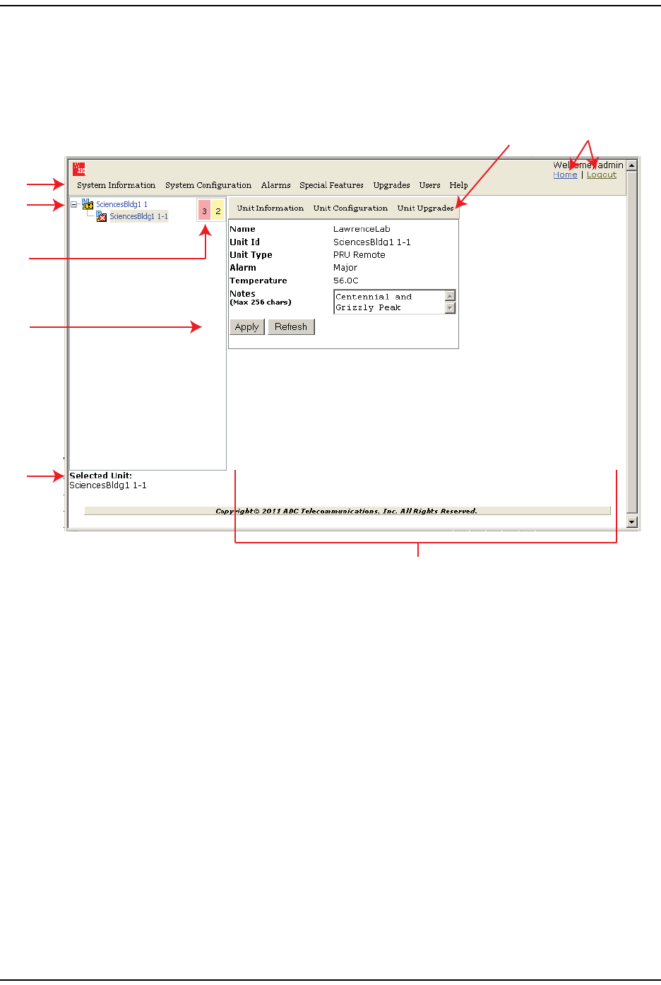
How to Use the EMS Graphical User Interface
Page 40 FlexWave Prism Element Management System 7.1 User Manual
© 2011 ADC Telecommunications, Inc ADCP-77-177 • Issue 1 • July 2011
HOW TO USE THE EMS GRAPHICAL USER INTERFACE
You use a web browser to access the EMS Graphical User Interface (GUI) shown
in Figure 15 and described in Table 10.
Figure 15. EMS Graphical User Interface
1
3
2
4
5
87
6
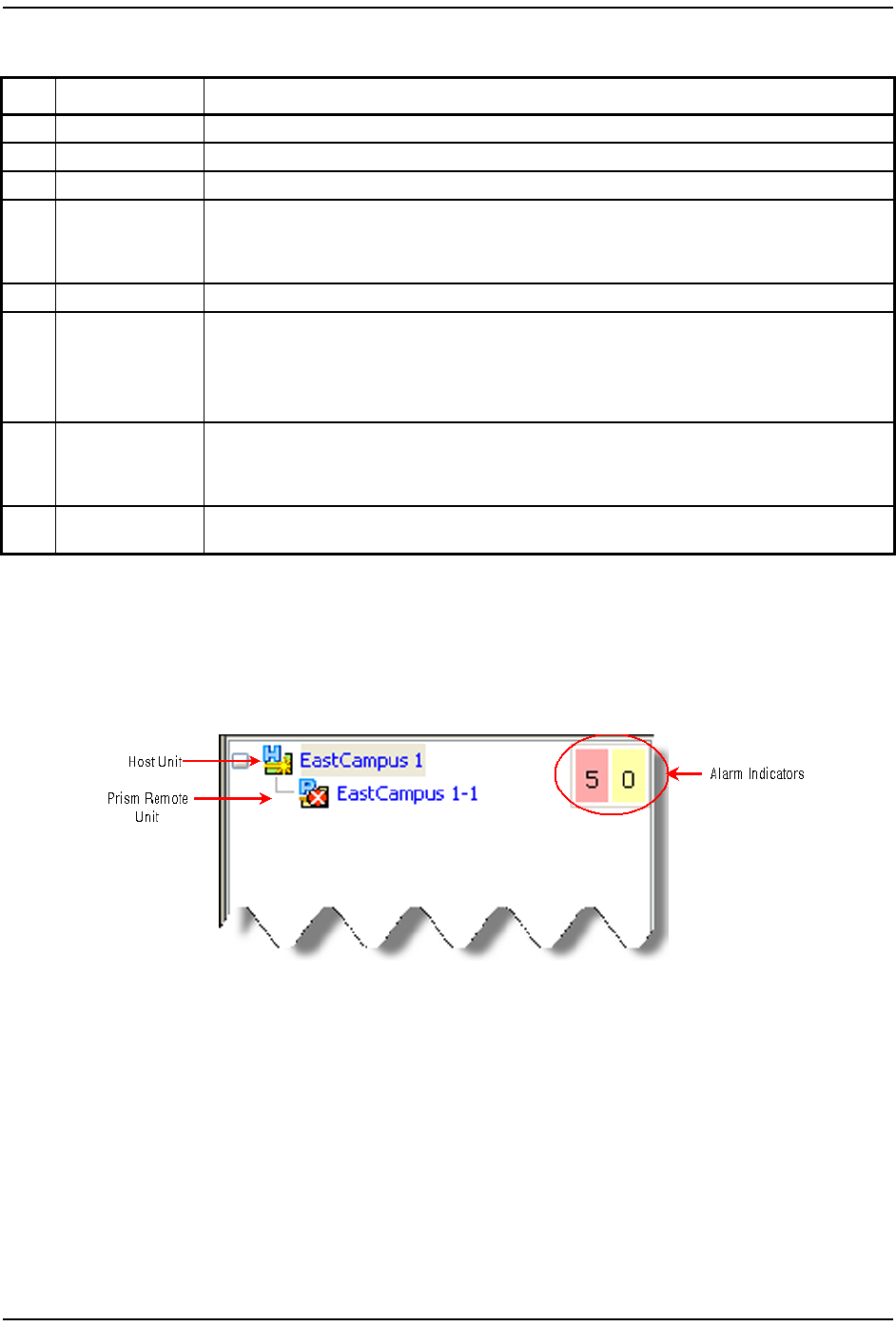
Using the Prism EMS
FlexWave Prism Element Management System 7.1 User Manual Page 41
ADCP-77-177 • Issue 1 • July 2011 © 2011 ADC Telecommunications, Inc.
System Tree
The System Tree displays a Prism system as device icons within a hierarchical tree
that is automatically organized by Unit ID:
You click on a node to navigate to a web page within the EMS View Frame that
corresponds to the selected unit.
The Alarm indicators in the upper-right corner of the System Tree let you know
how many active alarms there are, and at what severity level. In the preceding
figure, the Alarm indicators show:
•5 active Major alarms, as indicated by the red box
•0 active Minor alarms, as indicated by the yellow box.
Table 10. GUI Components
ID # Component Description
1System Menu bar Provides access to menus that allow you to configure or view system settings and alarms.
2System Tree See “System Tree” on page 41.
3Alarm indicators Provides a visual view of the number of active alarms and their severity level.
4Operational buttons
Execute the command for which the button is labeled:
•Apply—Applies your configuration changes without closing the dialog.
•Refresh—Updates status information to reflect current conditions.
5Unit Identifier Identifies which system component is selected in the System Tree.
6EMS View Frame
Provides the work space in which you access a Prism EMS web page specific to a unit or function.
NOTE: You can use your keyboard to navigate through the EMS pages:
•SPACE key on the keyboard scrolls down by a page
•SHIFT+SCROLL scrolls up one page.
7Orientation links
Provides links that allow you to navigate within the GUI:
•Home—returns you to the Home page
•Logout—logs you out of the EMS.
8Unit Menu bar Provides access to menus that allow you to configure or view settings and alarms that pertain to the
unit that is actively selected in the System Tree.
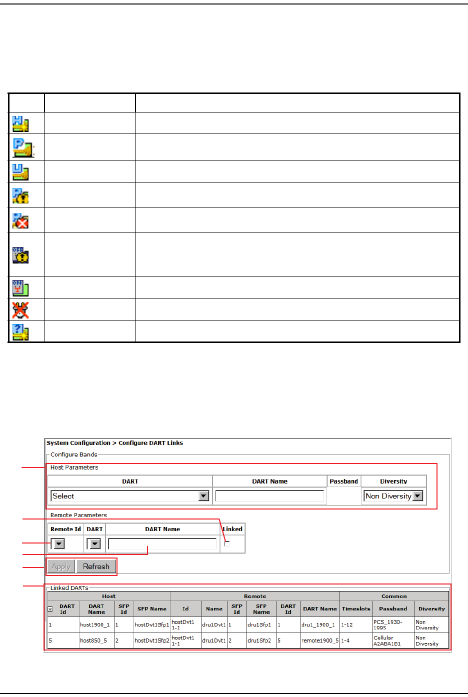
How to Use the EMS Graphical User Interface
Page 42 FlexWave Prism Element Management System 7.1 User Manual
© 2011 ADC Telecommunications, Inc ADCP-77-177 • Issue 1 • July 2011
System Tree Icons
Table 11 describes the icons used in the System Tree.
EMS View Frame Elements
Figure 16 and Table 12 describe the different elements found within the EMS View
Frame.
Figure 16. Elements within a View Frame
Table 11. System Tree Icons
Icon Unit/State Description
Host Host Unit; normal status
PRU Prism Remote Unit; normal status
URU Universal Radio Head Remote Unit; normal status
Minor Alarm State A yellow caution overlay on a unit icon indicates that the unit has an active Minor alarm. If
the icon is blinking, the alarm is unacknowledged.
Major Alarm State A red danger overlay on a unit icon indicates that the unit has an active Major alarm. If the
icon is blinking, the alarm is unacknowledged.
Contact Alarm State
Indicates a Contact Alarm state:
• Static—the alarm is acknowledged.
• Blinking—the alarm is unacknowledged.
No Contact Alarm State Indicates a No Contact Alarm state.
Disconnect Indicates that the unit is disconnected. Applicable only to PRUs and URUs.
Unknown Unit Identifies a unit that the EMS has found but cannot recognize.
1
2
3
4
5
6
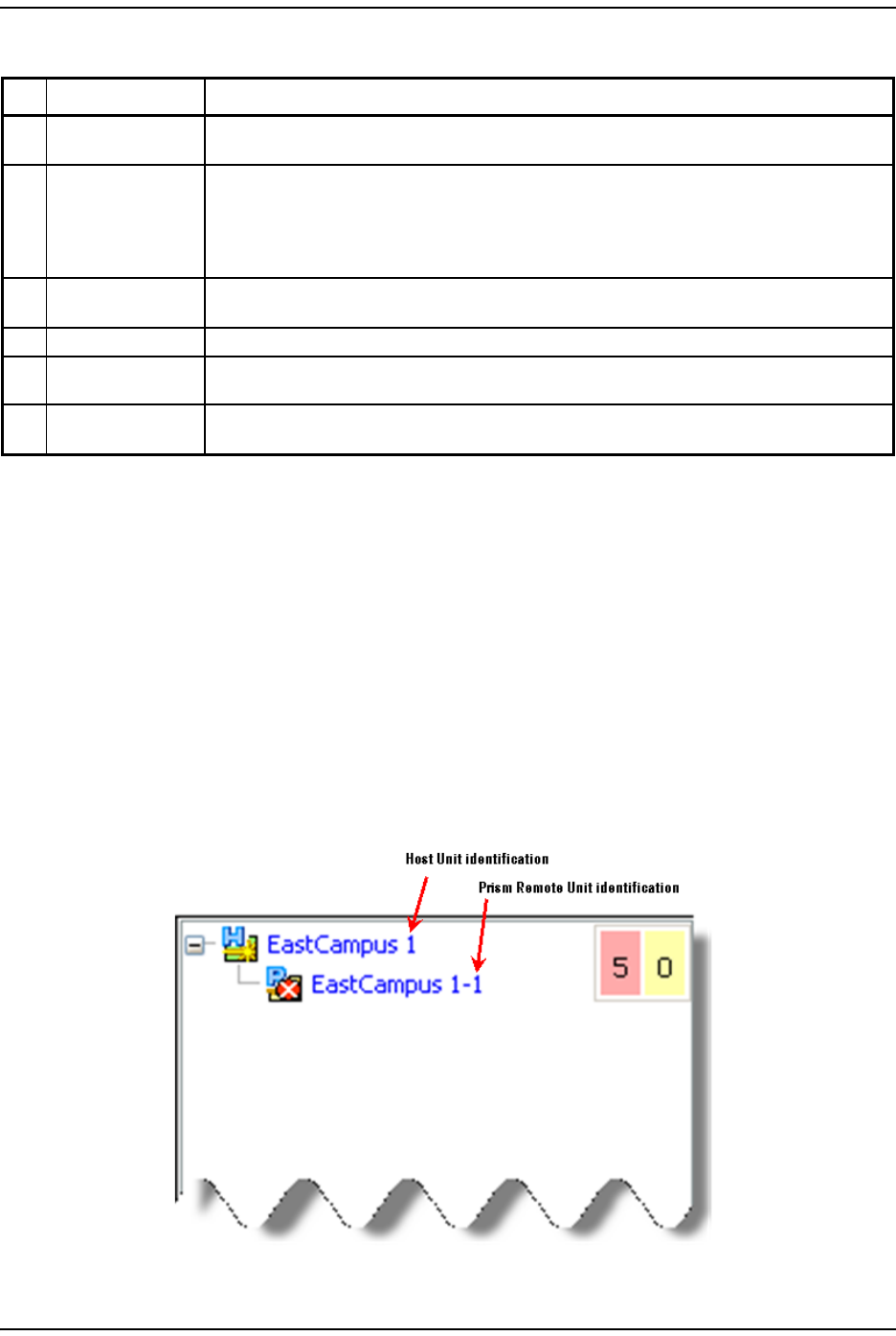
Using the Prism EMS
FlexWave Prism Element Management System 7.1 User Manual Page 43
ADCP-77-177 • Issue 1 • July 2011 © 2011 ADC Telecommunications, Inc.
NOTE: The View Frame is designed to update its contents within a web browser approximately
every 20 seconds.
Unit Identification
Figure 17 shows the Unit ID in the System Tree. The Unit ID is the hostname
(user-defined label) plus the layer address. The layered address is H-R, so the Unit
ID is <hostname>H-R, where:
•H—Host # is always 1
•R—Remote Unit # (PRU or URU), which can be 1 - 8 and is based on the SFP
port number to which the Remote Unit is connected
Figure 17. System Tree Unit IDs
Table 12. View Frame Elements
ID # Element Description
1Panel A panel is a grouping of fields or parameters enclosed within a grey box, with the panel title in the
upper-left corner.
2Selection box/Radio
button
A square box is a selection box that you click on to select or deselect an option. When selected, a
checkmark displays in the box. When the option is deselected, the box is empty.
If the selection box is round, it is referred to as a radio button. When a radio button is selected, the
round “button” is filled in. When a radio button is deselected, its circle is empty.
3List A menu that lists the options for the corresponding parameter. Click on the down arrow to display
the list.
4Text box A text box allows you to enter custom information for the corresponding field.
5Operational buttons Execute the command for which the button is labeled. When a button is greyed out, that function is
not available.
6Table A table collects information that corresponds to the EMS View Frame and provides it in table format.
The table is enclosed within a panel, with the table title in the upper-left corner.
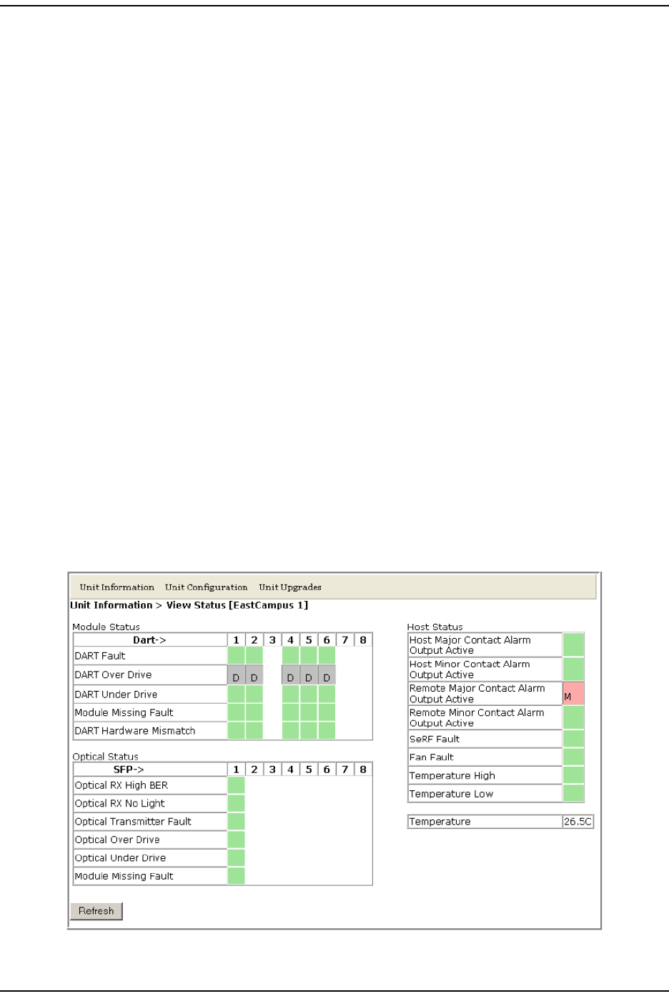
How to Use the EMS Graphical User Interface
Page 44 FlexWave Prism Element Management System 7.1 User Manual
© 2011 ADC Telecommunications, Inc ADCP-77-177 • Issue 1 • July 2011
Viewing Parameters and Alarms
You can view any parameter or alarm by navigating to the page in which the
parameter or alarm resides. To quickly find information about a parameter or
alarm:
•All parameters are listed alphabetically in this manual’s Index.
•All alarms are listed alphabetically in this manual’s Index of Alarms.
•All traps are listed alphabetically in this manual’s Index of Traps.
Alarm Color Codes
Alarms are color coded in the GUI according to the level of the alarm:
•Green—No alarm
•Blue—Information alarm, which provides information on a successful user
action, such as a change in a forward or reverse delay setting
•Yellow—Minor alarm
•Red—Major alarm
•Gray—the alarm has been disabled; see “Enable and Disable Host and Remote
Unit Alarms” on page 178
•White—a device has not been installed. For example, in Figure 18, which shows
the Unit Information > View Status page, the Module Status table shows that a DART
has not been installed in slots 3, 7, or 8. The Optical Status table shows that SFPs
are not installed in Optical ports 2 through 8.
Figure 18. Understanding Color Codes for Empty Slots