ADC Telecommunications PSMAWS2D FWP-A4MT000MOD User Manual
ADC Telecommunications Inc FWP-A4MT000MOD
User Manual
TECP-77-141 Issue 2 August 2012
300001744178 Rev B
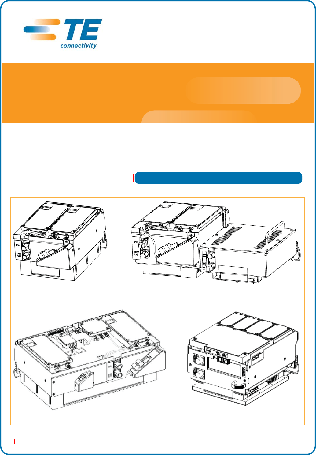
Dual-Band Dual-Slot RF Module
Single-Slot RF Module
Dual-Slot 40W RF Module HDM RF Module
FlexWave Prism®
RF Modules for Prism Remote Units
Installation Guide
Copyright
© 2012 TE Connectivity, Inc. All Rights Reserved.
Information contained in this document is company private to TE Connectivity Ltd., and shall not be modified,
used, copied, reproduced or disclosed in whole or in part without the written consent of TE.
Trademark Information
FlexWave, FlexWave Prism, InterReach Spectrum, InterReach Unison, Universal Radio Head, TE
Connectivity, and TE connectivity (logo) are trademarks.
All other logos, products and/or company names referred to herein might be trademarks of their respective
owners.
Disclaimer of Liability
Contents herein are current as of the date of publication. TE reserves the right to change the contents without
prior notice. Should the content of printed user documentation shipped with product differ from documentation
provided on a product CD (inclusive of the associated Help modules), the printed user documentation
supersedes the documentation on the product CD. In no event shall TE be liable for any damages resulting
from loss of data, loss of use, or loss of profits, and TE further disclaims any and all liability for indirect,
incidental, special, consequential or other similar damages. This disclaimer of liability applies to all products,
publications and services during and after the warranty period.
Specific Disclaimer for High-Risk Activities
This Product is not specifically designed, manufactured, tested or intended for use in high-risk activities
including, without restricting the generality of the foregoing, on-line control of aircraft, air traffic, aircraft
navigation or aircraft communications; or in the design, construction, operation or maintenance of any nuclear
facility. TE (including its affiliates) and its suppliers specifically disclaim any express or implied warranty of
fitness for such purposes or any other purposes.

FlexWave Prism RF Modules for Prism Remote Units Installation Guide Page 1
TECP-77-141 • Issue 1 • April 2012 ©2012 TE Connectivity Ltd.
TABLEOFCONTENTS
Topics Page
Preface .................................................................................................................................................................2
RevisionHistory...................................................................................................................................................... 2
FlexWavePrismUserDocumentation.................................................................................................................... 2
AccessingUserDocumentationontheCustomerPortal ...................................................................................................3
DocumentCautionsandNotes...........................................................................................................................................3
StandardsCertification........................................................................................................................................... 4
OverviewofRFModulesforPrismRemoteUnits..................................................................................................5
RFModuleComponents......................................................................................................................................... 8
DuplexerandLowNoiseAmplifier .....................................................................................................................................9
LinearPowerAmplifiers .....................................................................................................................................................9
DigitalProcessingModule ................................................................................................................................................10
RFModuleCables .............................................................................................................................................................10
RFModuleCablesforSingle‐Card,Dual‐Card,andHDMRFModules................................................... 10
RFModuleCablesforDual‐SlotInstallations......................................................................................... 12
PrismRemoteUnitRFGroupAssignments ......................................................................................................................13
PRURFModuleTypes .......................................................................................................................................... 16
PrismRemoteUnitSingle‐andDual‐CardRFModules ....................................................................................................16
PrismRemoteUnitHDMRFModules ..............................................................................................................................17
PrismRemoteUnitDual‐Slot40WRFModules................................................................................................................18
InstalltheRFModule(s)......................................................................................................................................19
SafetyPrecautions................................................................................................................................................ 19
GuardAgainstDamagefromElectro‐StaticDischarge......................................................................................... 20
UnpackandInspecttheRFModule ..................................................................................................................... 20
RemoveReleaseLinersfromtheRFModule ....................................................................................................... 21
Dual‐SlotModulesOnly—RemovetheModuleSlotShelf ................................................................................... 23
InstalltheRFModuleintothePrismRemoteChassis.......................................................................................... 24
SecureRFModuleLatches ................................................................................................................................... 32
ConnectLatchesonSingle‐SlotandHDMRFModules ....................................................................................................33
ConnectLatchesonDual‐BandDual‐SlotRFModules .....................................................................................................34
LatchesonDual‐Slot40WRFModules.............................................................................................................................35
VerifythattheRFModuleMountingHookisEngaged ....................................................................................................35
ConnecttheRFModuleCables ............................................................................................................................ 36
PowerontheRFModule...................................................................................................................................... 42
ContactingTEConnectivity .................................................................................................................................43
ContactingTEConnectivitybyTelephone............................................................................................................ 43
OnlineAccesstoTEConnectivity ......................................................................................................................... 43

Preface
Page 2 FlexWave Prism RF Modules for Prism Remote Units Installation Guide
© 2012 TE Connectivity Ltd TECP-77-141 • Issue 1 • April 2012
PREFACE
ThismanualprovidestheinformationyouneedtoinstallTEConnectivityFlexWavePrism®RF
ModulesintoaPrismRemoteUnit(PRU).Installationinstructionsareprovidedforthefollowing
PrismRemoteUnitRFModules:
•Single‐SlotRFModules,whichincludestheHDMRFModules
•Dual‐SlotRFModules
–Dual‐CardRFModules
–40WRFModules.
NOTE: ThisinstallationguidedocumentstheRFModulesthatarecompatiblewiththeFlexWavePrism
RemoteUnit,whichisdesignedforoutdooruse.ForinformationontheRFModulesdesignedfor
usewiththeFlexWavePrismIndoorRemoteUnits(IRUs),seetheFlexWavePrismIndoorRemote
UnitInstallationGuide(TECP‐77‐197).
RevisionHistory
Table 1. Revision History
Issue Document Date Technical Updates
1April 2012 Original
2December 2012 •Updated Table 2 on page 3 with new Prism user documentation list.
•Updated Table 3 on page 7 to add new RF Modules.
•Removed the Specifications section, which included the RF and Optical Specifications and the
Frequency and Composite Output Power at Antenna Port (dBm) for Prism Remote Units tables; to
access these performance specifications, refer to the Flexwave Prism Performance Specifications
(TECP-77-201).
•Updated “Contacting TE Connectivity” on page 43.
FlexWavePrismUserDocumentation
FlexWavePrismuserdocumentationisintendedforsystemadministrators,engineersand
installersresponsibleforplanning,administering,configuring,andmaintainingFlexWavePrism
systems.Table2onpage3liststhemanualsthatcorrespondtothefeaturesoftheFlexWave
PrismRFModulesdescribedinthisinstallationguide.

Table2.FlexWavePrismUserDocumentation
Title Catalog Number
ElementManagementSystem7.3and7.4UserGuideTECP-77-212
HostUnitIIInstallationGuide TECP-77-206
HostUnitExpansionUnitInstallationGuide TECP-77-202
HostUnitIIandHostUnitExpansionUnitModuleReplacementGuide TECP-77-207
PrismRemoteUnitInstallationGuide TECP-77-142
RFModulesforPrismRemoteUnitsInstallationGuide(1)TECP-77-141
IndoorRemoteUnitInstallationGuide TECP-77-197
OADMSpliceBoxInstallationGuide TECP-77-208
CoarseWavelengthDivisionMultiplexerUserGuide TECP-77-209
FlexwavePrismPerformanceSpecifications TECP-77-201
1 The Prism Remote RF Modules and Remote Mounting Kit are designed for use only in the Prism Remote
Unit (PRU). The IRU RF Modules and mounting options are described in the FlexWave Prism Indoor
Remote Unit Installation Guide (TECP-77-197).
FlexWave Prism User Documentation
FlexWave Prism RF Modules for Prism Remote Units Installation Guide Page 3
TECP-77-141 • Issue 1 • April 2012 © 2012 TE Connectivity Ltd.
AccessingUserDocumentationontheCustomerPortal
1ClickonthefollowingURLlinkorentertheURLintoyourwebbrowser,andthenpressEnter
onyourkeyboard:
http://www.adc.com/Americas/en_US/1268116693520
NOTE: AccesstotheCustomerPortalrequiresauseraccountandpassword.Ifyoudonothavean
account,clickontheregistrationlinkontheLogInpage.
2OntheCustomerPortalHomepage,clickManuals&SpecSheets.
3OntheManuals&SpecSheetspage,clickonthetitleofthemanualthatyouwishtoopenor
download.
DocumentCautionsandNotes
Twotypesofmessages,identifiedbelow,appearinthetext:
CAUTION! Cautiontextindicatesoperationsorstepsthatcouldcausepersonalinjury,induceasafety
probleminamanageddevice,destroyorcorruptinformation,orinterruptorstopservices.
NOTE: Notetextcontainsinformationaboutspecialcircumstances.

Preface
Page 4 FlexWave Prism RF Modules for Prism Remote Units Installation Guide
© 2012 TE Connectivity Ltd TECP-77-141 • Issue 1 • April 2012
StandardsCertification
FCC:ThisequipmentcomplieswiththeapplicablesectionsofTitle47CFRPart15(HostUnit),Part
22(800MHzCellular),Part24(1900MHz‐PCS),Part90(800/900‐SMR),andPart27(2100
MHz‐AWS)&(700MHz‐LTE).
IC:ThisequipmentcomplieswiththeapplicablesectionsofRSS‐131.Theterm“IC:”beforethe
radiocertificationnumberonlysignifiesthatIndustryCanadaTechnicalSpecificationsweremet.
TheManufacturer'sratedoutputpowerofthisequipmentisforsinglecarrieroperation.For
situationswhenmultiplecarriersignalsarepresent,theratingwouldhavetobereducedby3.5
dB,especiallywheretheoutputsignalisre‐radiatedandcancauseinterferencetoadjacentband
users.Thispowerreductionistobebymeansofinputpowerorgainreductionandnotbyan
attenuatorattheoutputofthedevice.
Note:TocomplywithMaximumPermissibleExposure(MPE)requirements,themaximum
compositeoutputfromtheantennacannotexceed1000WattsERP(LTE,CellularandSMR),the
antennacannotexceed1640WattsEIRP(PCSandAWS),andtheantennamustbepermanently
installedinafixedlocationthatprovidesatleast6meters(20feet)ofseparationfromallpersons.
UL/CUL:Thiswillbeinstalledinarestrictedaccesslocation.ThisequipmentcomplieswithType
4,perULandCUL50,StandardforEnclosuresforElectricalEquipment.Thisequipmentprovides
thedegreeofprotectionspecifiedbyIP66asdefinedinIECPublication529.
FDA/CDRH:ThisequipmentusesaClass1LASERaccordingtoFDA/CDRHRules.Thisproduct
conformstoallapplicablestandardsof21CFRPart1040.
Caution:Modificationsnotexpresslyapprovedbythepartyresponsibleforcompliancecould
voidtheuser'sauthoritytooperatetheequipment.
EUHarmonizedStandards:MeetsessentialrequirementsofR&TTE1999/5/EC.
•Article3.1a—Theprotectionofthehealthandthesafetyoftheuserandanyotherperson,
includingtheobjectiveswithrespecttosafetyrequirementscontainedinDirective
2006/95/EC,butwithnovoltagelimitapplying.
•Article3.1b—Theprotectionrequirementswithrespecttoelectromagneticcompatibility
containedinDirective2004/108/EC.
•Article3.2—Inaddition,radioequipmentshallbesoconstructedthatiteffectivelyuses
thespectrumallocatedtoterrestrial/spaceradiocommunicationandorbitalresourcesso
astoavoidharmfulinterference.
EMCStandards:EN55022andEN55024(CEmarked)
SafetyStandards:
•IEC60950‐1,FirstEdition(CEmarked)
•UL60950‐1(FilenumberE174166)(USAandCanada)
Standards Certification
FlexWave Prism RF Modules for Prism Remote Units Installation Guide Page 5
TECP-77-141 • Issue 1 • April 2012 © 2012 TE Connectivity Ltd.
OVERVIEWOFRFMODULESFORPRISMREMOTEUNITS
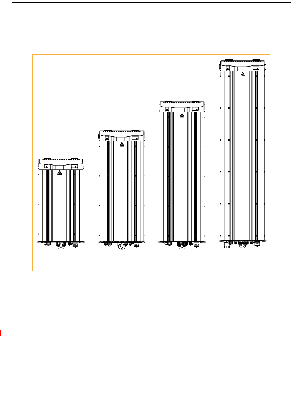
Figure1illustratesthePrismRemoteUnit(PRU),whichcontrolsRFemissions,interfaceswith
theFlexWaveHost.
Single-Band
Remote
Dual-Band
Remote
Tri-Band
Remote
Quad-Band
Remote
Figure1.Prism Remote Units
ThePRUhasfromonetofourRFModuleslots,dependingonthePRUmodel.Thatis,the
Single‐BandPRUhasoneRFModuleslot,andtheQuad‐BandPRUhasfourRFModuleslots.APRU
cansupportuptofourRFModules.
ThefunctionofthePRURFModulesontheForwardPathisto:
•convertthedigitizedRFtransportedfromtheHosttoAnalogRF
•amplifytheAnalogRFsignal
•providesignalfiltering.
ThefunctionofthePRURFModulesontheReversePathisto:
•converttheAnalogRFfromthehandsettoDigitalRFfortransporttotheHost
•providesignalfiltering.

Overview of RF Modules for Prism Remote Units
Page 6 FlexWave Prism RF Modules for Prism Remote Units Installation Guide
© 2012 TE Connectivity Ltd TECP-77-141 • Issue 1 • April 2012
EachRFModulecansupportanyofthefollowingDARTcombinations:
•oneClassicDARToroneSingleSuperDART
•twoClassicDARTs
•twoSingleSuperDARTs
•oneDualSuperDART
•oneortwosetsofTxorRxBoards(HDM)
–HDM‐850hasoneset
–HDM‐700hastwosets.
EachRFModulewillhaveuptotwo6‐TimeslotDARTsorone12‐TimeslotDARTsperRFModule.
TheRFModulesarefieldreplaceable,butcannotbeservicedinthefield.
Table3onpage7liststhePrismRemoteUnitRFModulesthataresupportedinthisinstallation
guide.

Table3.SupportedFlexWavePrismRFModulesforPrismRemoteUnits(PRUs)
Catalog Number Description
10W 900 P-GSM Module, Diversity, SGL SD
10w 900 P-GSM Module, Non-Diversity, SGL SD
10W APAC EGSM (885-915) MODULE, SGL SD
10W, EGSM 900, DIVERSITY, SGL SD
10W, EGSM 900, NON-DIVERSITY, SGL SD
20W 2100 UMTS MODULE, DIV Ready, SGL SD
20W 700 Lower ABC MODULE, NON-DIVERSITY, SGL SD
20W AWS MODULE, DIVERSITY, SGL SD
20W AWS MODULE, NON-DIVERSITY, SGL SD
20W PCS MODULE, DIVERSITY, SGL SD
20W PCS MODULE, NON-DIVERSITY, SGL SD
20W RF Module, AWS 2100 12S Enclosure
20W RF Module, AWS 2100 Diversity Enclosure
20W RF Module, AWS 2100 Non-Diversity Enclosure
20W RF Module, PCS 1900 12S Enclosure
20W RF Module, PCS 1900 Diversity Enclosure
20W RF Module, PCS 1900 Non-Diversity Enclosure
20W WIDEBAND CELL MODULE, DIVERSITY, CLASSIC
20W WIDEBAND CELL MODULE, NON-DIVERSITY, Classic
20W, GSM 1800, DIVERSITY, SGL SD
20W, GSM 1800, NON-DIVERSITY, DL SD
20W, GSM 1800, NON-DIVERSITY, SGL SD
20W, UMTS 2100, DIVERSITY, SGL SD
20W, UMTS 2100, NON-DIVERSITY, DL SD
20W, UMTS 2100, NON-DIVERSITY, SGL SD
40W 700 Upper C MODULE, NON-DIVERSITY, SGL SD (SGL-SLOT)
40W AWS MODULE, NON-DIVERSITY, CLASSIC
40W AWS MODULE, NON-DIVERSITY, SGL SD (DUAL-SLOT)
40W PCS MODULE, NON-DIVERSITY, CLASSIC (DUAL-SLOT)
40W PCS MODULE, NON-DIVERSITY, SGL SD (DUAL-SLOT)
40W WIDEBAND CELL MODULE, NON-DIVERSITY, (SGL-SLOT)
6.5W 800 SMR MODULE, NON-DIVERSITY, CLASSIC
6.5W 800/900 ESMR MODULE, NON-DIVERSITY, CLASSIC
6.5W APAC iDEN Module, Non-Diversity, Classic (Extended 1 MHz)
700 LTE, UPPER C, 20W MODULE, SISO, SGL SD
DUAL 20W 700 LOWER ABC MODULE, MIMO
DUAL 20W 700 UPPER C MODULE, MIMO
DUAL 20W 850/1900 RF MODULE, (SGL BAY)
DUAL 20W 2100 RF MODULE, MIMO, (SGL BAY)
40W AWS MODULE, NON-DIVERSITY, SGL SD (SGL-Bay)
PRISM, 40W PCS MODULE, NON-DIVERSITY, SGL SD (SGL BAY)
Standards Certification
FlexWave Prism RF Modules for Prism Remote Units Installation Guide Page 7
TECP-77-141 • Issue 1 • April 2012 © 2012 TE Connectivity Ltd.
FWP-K226000MOD
FWP-K216000MOD
FWP-F216000MOD
FWP-6226000MOD
FWP-6216000MOD
FWP-9416D00MOD
FWP-L416000MOD
FWP-A426000MOD
FWP-A416000MOD
FWP-8426000MOD
FWP-8416000MOD
FWP-A41S000MOD
FWP-A420000MOD
FWP-A410000MOD
FWP-841S000MOD
FWP-8420000MOD
FWP-8410000MOD
FWP-B420000MOD
FWP-B410000MOD
FWP-7426000MOD
FWP-741S000MOD
FWP-7416000MOD
FWP-9426000MOD
FWP-941S000MOD
FWP-9416000MOD
FWP-U816100MOD
FWP-A810000MOD
FWP-A816000MOD
FWP-8810000MOD
FWP-8816000MOD
FWP-B810100MOD
FWP-4210000MOD
FWP-D210000MOD
FWP-I210000MOD
FWP-U416000MOD
FWP-L4MT000MOD
FWP-U4MT000MOD
FWP-C4MT000MOD
FWP-A4MT000MOD
FWP-A81T000MOD
FWP-881T000MOD
Overview of RF Modules for Prism Remote Units
Page 8 FlexWave Prism RF Modules for Prism Remote Units Installation Guide
© 2012 TE Connectivity Ltd TECP-77-141 • Issue 1 • April 2012
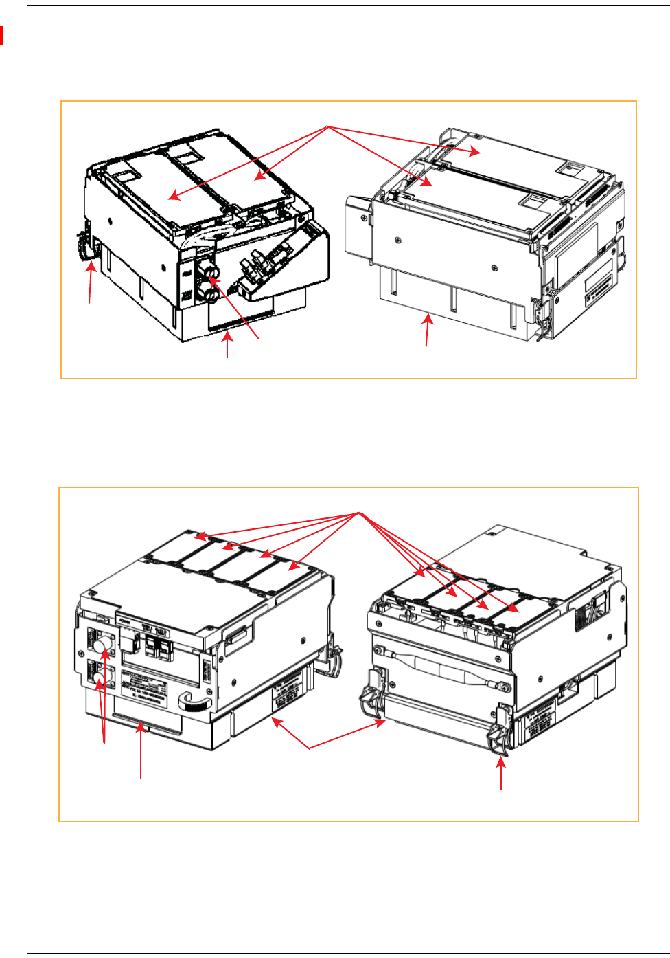
RFModuleComponents
Figure2showstypicalRFModulecomponents,usingtheSingle‐SlotRFModuleasanexample.
Mounting
latch
Mounting hook
Duplexer Power Amplifier (PA)
DARTs
Figure2.PRU Single-Slot RF Module Components
Figure3showsthecomponentsofanHDMRFModule.
Duplexers Power Amplifier
Mounting latch
Mounting hook
Tx and Rx Cards
Figure3.HDM RF Module Components

RF Module Components
FlexWave Prism RF Modules for Prism Remote Units Installation Guide Page 9
TECP-77-141 • Issue 1 • April 2012 © 2012 TE Connectivity Ltd.
DuplexerandLowNoiseAmplifier
TheRFModuleprovidesthePRUwithaninternalDuplexerthatisoptimizedtoprovidethe
desiredRFband‐passfilteringandin‐bandequipmentisolationbetweenFWDandREVpaths.
TheDuplexerprovidesthefilteringnecessarytothetransmitandreceivepathstotheconnected
antenna.
TheDuplexerforthePrismRemoteUnitSingle‐andDual‐CardRFModulesandtheDual‐Slot40W
RFModulescontainsuptotwoREVpathLowNoiseAmplifiers(LNAforPRIand/orSECreverse
paths).EachLNAprovidesthePrismreversepathwithnominal30dBREVgainandsystemNFof
5dBperRXpath.
TheDuplexerforanHDMRFModuledoesnothaveaLowNoiseAmplifier.
Duplexersarenotfieldserviceable.
LinearPowerAmplifiers
TheLinearPowerAmplifier(LPA)isahighqualitybroadbandRFamplifierusedforachieving
Prismproduct‐ratedpowerforthePRUTxforwardpathspectrumRF.ThePAsarepass‐band
specific,withthemaximumcompositeTxpowerlevels,and>10dBinstantaneouspeakpower
ratinglistedin:
•Table4forSingle‐Card,Dual‐Card,andHDMRFModules
•Table5onpage10forDual‐Slot40WRFModules.
TheLPAishousedwithintheRFModule,andisnotfieldserviceable.
Table4.LPAMaximumCompositeTxPowerLevelsforSingle‐Card,Dual‐Card,andHDMRFModules
Passband Maximum
dBm
Watts Instantaneous
Bandwidth
(MHz)
AWS 2100 +43 20 45
Cellular 850 +43 20 25
+46 40 25
EGSM 900 +40 10 35
DCS 1800 +42 15.8 75
LTE 700 Lower ABC +43 20 18
+46 40 18
LTE 700 Upper C +43 20 10
+46 40 10
PCS 1900 +43 20 70
PGSM 900 +40 10 25
SMR 800 +38 6.5 18
SMR 900 +38 6.5 5
UMTS 2100 +42 15.8 60

Table5.LPAMaximumCompositeTxPowerLevelsforDual‐Slot40WRFModules
Passband Maximum
dBm
Watts Instantaneous
Bandwidth (MHz)
PCS 1900 +46 40 70
AWS 2100 +46 40 45
Overview of RF Modules for Prism Remote Units
Page 10 FlexWave Prism RF Modules for Prism Remote Units Installation Guide
© 2012 TE Connectivity Ltd TECP-77-141 • Issue 1 • April 2012
DigitalProcessingModule
TheDigitalProcessingModule(DPM)isfoundonlyintheHDMRFModules.TheDPMprovides
theprimaryprocessingandlogicfunctionsfortheHDMRFModule.Italsoprovidestheprimary
powerinterfacefortheHDMRFModule,andconversionofthenative28VDCvoltagetolower
voltagesasnecessaryforfunctionality.
TheDPMhasaTransmit(Tx)BoardandaReceive(Rx)Board:
•TxBoard—providesbandspecificfilteringfortheintendedTransmitpath.
•RxBoard—providesbandspecificfilteringfortheintendedReceivepath.
RFModuleCables
TheRFModulecablesthatarepre‐installedinthePRUconnecttothecorrespondingconnectors
ontheRFModule.TheRFModulecablescorrelatetotheantennaconnectorsonthebottomofthe
PRUchassis.
RFModuleCablesforSingle‐Card,Dual‐Card,andHDMRFModules
TheRFcableandconnectorlabelsalsocorrespondtotheRFModuleslotsinthePRUchassis,
whereMODAisthebottomslotandMODDisthetopslot.Intheinstallationsteps,theRFcables
andconnectorsarereferredtoasMODNTX0/RX0andasMODNTRX1whereNequalsA,B,C,orD.
ThecablesandconnectorshavecorrespondinglabelsasshowninTable6forSingle‐Card,
Dual‐Card,andHDMRFModules.

Table6.RFAntennaLabelsforSingle‐Card,Dual‐Card,andHDMRFModules—FromTopofChassisDown
RF Module
Cable,
RF Module
Connector,
and Remote
Antenna
Connector
Label
Function
Single-Slot
Remote Unit RF
Module Slot
Designations
Dual-Slot Remote Unit RF Module Slot
Designations
Dual-Band Tri-Band Quad-Band
Mod D
TX0/RX0
Transmit RF power and primary receive
to/from the antenna for RF Module D
MOD D N/A N/A MOD C
Mod D
TX1/RX1
Diversity receive for RF power from the
antenna for RF Module D
Mod C
TX0/RX0
Transmit RF power and primary receive
to/from the antenna for RF Module C
MOD C N/A MOD B
Mod C
TX1/RX1
Diversity receive for RF power from the
antenna for RF Module C
Mod B
TX0/RX0
Transmit RF power and primary receive
to/from the antenna for RF Module B
MOD B MOD A MOD B
Mod B
TX1/RX1
Diversity receive for RF power from the
antenna for RF Module B
Mod A
TX0/RX0
Transmit RF power and primary receive
to/from the antenna for RF Module A
MOD A MOD A MOD A
Mod A
TX1/RX1
Diversity receive for RF power from the
antenna for RF Module A
RF Module Components
FlexWave Prism RF Modules for Prism Remote Units Installation Guide Page 11
TECP-77-141 • Issue 1 • April 2012 © 2012 TE Connectivity Ltd.

Overview of RF Modules for Prism Remote Units
Page 12 FlexWave Prism RF Modules for Prism Remote Units Installation Guide
© 2012 TE Connectivity Ltd TECP-77-141 • Issue 1 • April 2012
RFModuleCablesforDual‐SlotInstallations
ForDual‐Slotinstallations,theRFcablesandconnectorsarelabeledasMODNTX0/RX0andMODN
TX1/RX1,whereNreferstothebottomslotofthedouble‐slotinstallation.Forexample,fora
Dual‐SlotinstallationinaQuad‐Bandchassis,theRFcablesandconnectorsarelabeledasMODC
TX0/RX0andMODCTX1/RX1.
ThecablesandconnectorshavecorrespondinglabelsasshowninTable7onpage12for
Dual‐Slot40WRFModules.
Table7.RFAntennaLabelsforDual‐Slot40WRFModules(TopofChassisDown)
RF Module
Cable,
RF Module
Connector,
and Remote
Antenna
Connector
Labels
Function
Slots for 40W RF Modules (a) (b)
Dual-Band Tri-Band Quad-Band
Mod D
TX0/RX0
Transmit RF power and primary receive
to/from the antenna for RF Module D
N/A N/A Slots C and D
Mod D RX1 Diversity receive for RF power from the
antenna for RF Module D
Mod C
TX0/RX0
Transmit RF power and primary receive
to/from the antenna for RF Module C
N/A N/A
Mod C RX1 Diversity receive for RF power from the
antenna for RF Module C
Mod B
TX0/RX0
Transmit RF power and primary receive
to/from the antenna for RF Module B
Slots A and B Slots A and B Slots A and B
Mod B RX1 Diversity receive for RF power from the
antenna for RF Module B
Mod A
TX0/RX0
Transmit RF power and primary receive
to/from the antenna for RF Module A
Mod A RX1 Diversity receive for RF power from the
antenna for RF Module A
(a) N/A indicates that the slot cannot be used for a Dual-Slot 40W RF Module
(b) Install the Dual-Slot 40W RF Module in the lower-most slot in the chassis. If, however, if two Dual-SLot
40W RF Modules are present, install the 2100 Module in the lower-most slot and the 1900 Module in the
upper-most slot.
RF Module Components
FlexWave Prism RF Modules for Prism Remote Units Installation Guide Page 13
TECP-77-141 • Issue 1 • April 2012 © 2012 TE Connectivity Ltd.
PrismRemoteUnitRFGroupAssignments
A Prism Remote Unit (PRU) comprises from one to four RF Module slots. Figure 4
illustrates the numbering of RF Module slots and DARTs.
Prism Quad-Band Remote Unit
with Single-Card RF Modules
SeRF Module
DART 7
DART 8
Group D
DART 5
DART 6
Group C
DART 3
DART 4
Group B
DART 1
DART 2
Group A
Figure 4. DART RF Groups in a Prism Remote Unit (PRU)
Overview of RF Modules for Prism Remote Units
Page 14 FlexWave Prism RF Modules for Prism Remote Units Installation Guide
© 2012 TE Connectivity Ltd TECP-77-141 • Issue 1 • April 2012
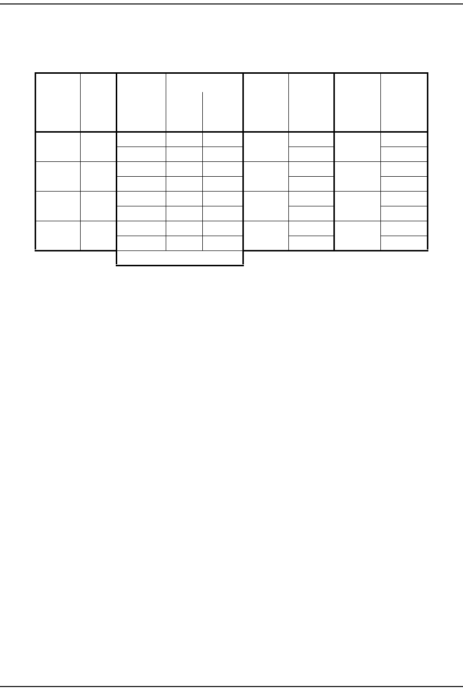
Table 8 lists how the FlexWave Prism EMS references the RF group assignments
and corresponding components of each RF Module.
Table 8. Remote Unit RF Group Assignments (from Top/Down)
Physical
RF Slot
RF
Group
DART
Number
LNA Number LPA
Number
for Single
LPA
LPA
Number
for Dual
LPAs
Power
Detector
Number
for Single
PD
Power
Detector
Number
for Dual
PDs
Primary Diversity
D D 8 8 7878
7 7 7 7
C C 6 6 5656
5 5 5 5
B B 4 4 3434
3 3 3 3
A A 2 2 1212
1 1 1 1
SeRF Board
NOTE: In a dual-LPA system, the Configure Remote Forward Gain page shows two values for the LPA
status, one for each LPA. Changing the LPA Mode or resetting the LPA applies to both LPAs at the
same time.
CAUTION! Should your system experience an LPA problem, refer to Table 8 to ensure that you apply new
settings or troubleshoot the correct RF Module.
CAUTION! If you use a customized SNMP polling for system status, you must change your LPA indexing
scheme.
RF Module Components
FlexWave Prism RF Modules for Prism Remote Units Installation Guide Page 15
TECP-77-141 • Issue 1 • April 2012 © 2012 TE Connectivity Ltd.
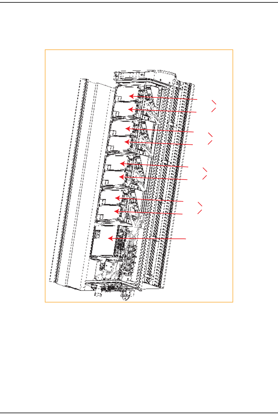
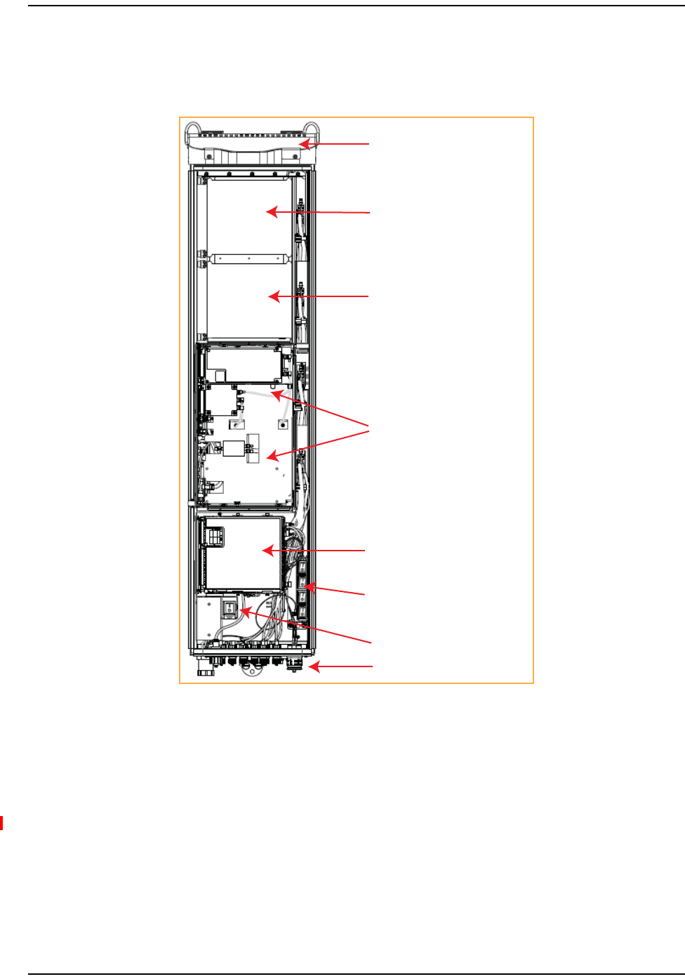
TheDual‐Slot40WRFModuleoccupiestwoslotsinaPrismRemote.Figure5showsthemain
componentsinaPrismenclosure,witha40WRFModuleoccupyingSlotsAandB.Thecontrolling
DARTwillalwaysbeintheupperslot(BorD),andthesecondLPAisalwaysinthelowerslot(A
orC).
Dual-slot 40W RF Module
in Slot B (upper slot) and
Slot A (lower slot) with the
controlling DART in Slot B
and the second DART in Slot A
AC power switch
Four DC power switches
SeRF Module and Power supplies
Slot C (empty for future use)
Slot D (empty for future use)
Fans
Connectivity panel with Status LED
Figure5.Dual-Slot 40W RF Module in a Quad-Band Prism Remote
NOTE: IfaDual‐Slot40WRFModuleAWS2100andaDual‐Slot40WRFModulePCS1900areboth
installedinaQuad‐BandRemote,itisrecommendedthatthePCS1900beinstalledin
upper‐mostslot,andtheAWS2100beinstalledinthelower‐mostslot.
NOTE: Toaccommodatetwo‐slotmodules,youneedtoremoveamoduleslotshelfasdescribedin
“Dual‐SlotModulesOnly—RemovetheModuleSlotShelf”onpage23.
Overview of RF Modules for Prism Remote Units
Page 16 FlexWave Prism RF Modules for Prism Remote Units Installation Guide
© 2012 TE Connectivity Ltd TECP-77-141 • Issue 1 • April 2012
PRURFModuleTypes
ThePRURFModulesareavailableinthefollowingformats,andasdescribedinthefollowing
sections:
•“PrismRemoteUnitSingle‐andDual‐CardRFModules”onpage16
•“PrismRemoteUnitHDMRFModules”onpage17
•“PrismRemoteUnitDual‐Slot40WRFModules”onpage18.
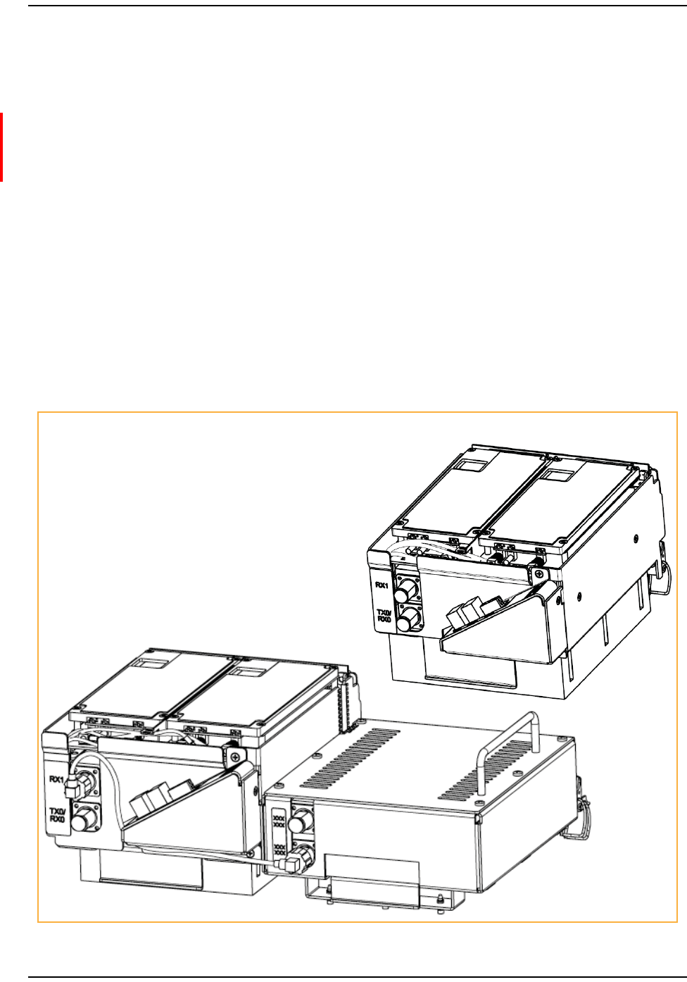
PrismRemoteUnitSingle‐andDual‐CardRFModules
Figure6showsexamplesofPRUSingle‐andDual‐SlotRFModules,bothofwhichhavetwo
DARTs.APRUSingle‐andDual‐CardRFModulecomprises:
•oneDART
•oneDuplexerwithoneortwointernalLowNoiseAmplifiers(LNAs)
•oneLinearPowerAmplifier(LPA)
Dual-Band Dual-Slot RF Module
Single-Slot Dual-Card RF Module
•oneRemoteDARTInterface(RDI)board.
Figure6.Single- and Dual-Slot RF Modules
PRU RF Module Types
FlexWave Prism RF Modules for Prism Remote Units Installation Guide Page 17
TECP-77-141 • Issue 1 • April 2012 © 2012 TE Connectivity Ltd.
PrismRemoteUnitHDMRFModules
PRUHDMRFModules(Figure7)aredesignedfor850Cellfrequencies.Theinitialreleaseofthe
HDMRFModuleisaSingleInputSingleOutput(SISO)Configurationthat
•interfacesoneHostDART—eitherClassicorSuperDART
•supportstwonon‐contiguousRFslicesupto25MHztotalbandwidth—SuperDARTonly
•supportsupto40WRFoutputpower.
Figure7.HDM RF Module
ThecomponentsofaPRUHDMRFModuleisdependentonthemoduletype,aslistedinTable9.
Table9.ComponentsofPRUHDMRFModules
RF Module Type DPM LPA Duplexer Rx Card Tx Card
SISO 1 1 1 1 1
Diversity* 1 1 2 2 1
MIMO* 1 2 2 2 2
* Not supported in this release.
Overview of RF Modules for Prism Remote Units
Page 18 FlexWave Prism RF Modules for Prism Remote Units Installation Guide
© 2012 TE Connectivity Ltd TECP-77-141 • Issue 1 • April 2012
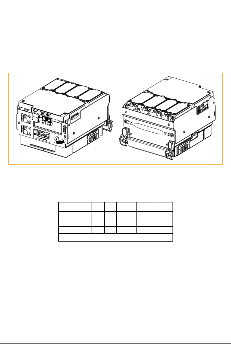
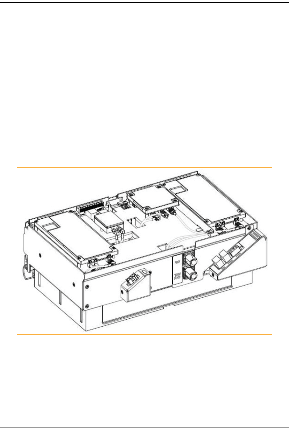
PrismRemoteUnitDual‐Slot40WRFModules
TheFlexWavePRUDual‐Slot40WRFModule(Figure2)isdesignedforAWSandPCSfrequencies.
ThePrismRemote40WRFModulecomprises:
•oneDART
•twoPowerAmplifiers(PAs)
•oneRemoteDARTInterface(RDI)board.
ThePrismRemote40WRFDiversityModulecomprises:
•twoDARTs
•twoPowerAmplifiers(PAs)
•twoRDIboards.
NOTE: ThismanualdescribeshowtoinstallthePCS1900andAWS2100Non‐DiversityRFModules.
Figure8.Dual-Slot 40W RF Module

Safety Precautions
FlexWave Prism RF Modules for Prism Remote Units Installation Guide Page 19
TECP-77-141 • Issue 1 • April 2012 © 2012 TE Connectivity Ltd.
INSTALLTHERFMODULE(S)
Thefollowing8sectionscomprise16stepsthatguideyouthroughtheinstallationofanRF
ModuleintoaPRUchassis.TheprocesstoinstallthefourdifferenttypesofRFModulesis
basicallythesame.
NOTE: Inthefollowingsteps,theRFcablesandconnectorsarereferredtoasMODNTX0/RX0andas
MODNTRX1whereNequalsA,B,C,orD.
SafetyPrecautions
CAUTION! Thisisrestrictedaccessequipmentandonlyqualifiedservicepersonnelshouldserviceand
operatethisequipmentusingappropriatetools.
CAUTION! Wetconditionsincreasethepotentialforreceivinganelectricalshockwheninstallingorusing
electrically‐poweredequipment.Topreventelectricalshock,neverinstalloruseelectrical
equipmentinawetlocationorduringalightningstorm.
CAUTION! Alwaysallowsufficientfiberlengthtopermitroutingofpatchcordsandpigtailswithoutsevere
bends.Fiberopticpatchcordsorpigtailsmaybepermanentlydamagedifbentorcurvedtoa
radiusoflessthan2inches(5.1cm).
CAUTION! ExteriorsurfacesofthePrismRemoteUnitmaybehot.Usecautionduringservicing.
CAUTION! Servicepersonnelmustconfirmthattheperimetergasketanddoor‐to‐doorgasketsareinplace
whenclosingthePrismdoorsafterservicing.
CAUTION! ThisequipmentusesaClass1LaseraccordingtoFDA/CDRHrules.Laserradiationcanseriously
damagetheretinaoftheeye.Donotlookintotheendsofanyopticalfiber.Donotlookdirectly
intotheopticaltransceiverofanydigitalunitorexposuretolaserradiationmayresult.An
opticalpowermetershouldbeusedtoverifyactivefibers.AprotectivecaporhoodMUSTbe
immediatelyplacedoveranyradiatingtransceiveroropticalfiberconnectortoavoidthe
potentialofdangerousamountsofradiationexposure.Thispracticealsopreventsdirtparticles
fromenteringtheadapterorconnector.
CAUTION! ThissystemisanRFTransmitterandcontinuouslyemitsRFenergy.Maintain3foot(91.4cm)
minimumclearancefromtheantennawhilethesystemisoperating.Whereverpossible,shut
downtheRANbeforeservicingtheantenna.

Install the RF Module(s)
Page 20 FlexWave Prism RF Modules for Prism Remote Units Installation Guide
© 2012 TE Connectivity Ltd TECP-77-141 • Issue 1 • April 2012
GuardAgainstDamagefromElectro‐StaticDischarge
CAUTION! Electro‐StaticDischarge(ESD)candamageelectroniccomponents.TopreventESDdamage,
alwayswearanESDwriststrapwhenworkingwiththeIRUorwhenhandlinganyofits
components.ConnectthegroundwireontheESDwriststraptoanearthgroundsourcebefore
touchingtheIRUoranyofitscomponents.Wearthewriststraptheentiretimethatyouwork
withtheIRUanditscomponents.
CAUTION! PlacethePRismRFModulesinanti‐staticpackingmaterialwhentransportingorstoringthem.
UnpackandInspecttheRFModule
1UnpackandinspecttheRFModule.
aInspecttheexterioroftheshippingcontainer(s)forevidenceofroughhandlingthatmay
havedamagedthecomponentsinthecontainer.
bUnpackeachcontainerwhilecarefullycheckingthecontentsfordamageandverifywith
thepackingslip.
cIfdamageisfoundorpartsaremissing,fileaclaimwiththecommercialcarrierandnotify
TECustomerService(see“ContactingTEConnectivity”onpage43).Savethedamaged
cartonsforinspectionbythecarrier.
dSaveallshippingcontainersforuseiftheequipmentrequiresshipmentatafuturedate.
CAUTION! HandletheRFModulewithcareduringinstallation.Beespeciallycarefultonotdamagethe
thermal‐interfacematerial(TIM),whichisattachedtotheLPA.IftheTIMisdamaged,theLPA
canoverheat.BeforeinstallingtheRFModule,checktoseeiftheheatsinkmaterialisgougedor
cracked.IftheTIMisdamaged,donotinstalltheRFModuleandcontactTEConnectivityfor
assistance(see“ContactingTEConnectivity”onpage43forcontactinformation).
CAUTION! Ifthethermal‐interfacematerialisdamaged,theinstallationanduseoftheRFModulemayvoid
thewarrantyoftheRFModule.
Remove Release Liners from the RF Module
FlexWave Prism RF Modules for Prism Remote Units Installation Guide Page 21
TECP-77-141 • Issue 1 • April 2012 © 2012 TE Connectivity Ltd.
RemoveReleaseLinersfromtheRFModule
NOTE: ReleaseLinersarepresentonfrontandbackofnewmodules.
2OpenthePRUenclosure.
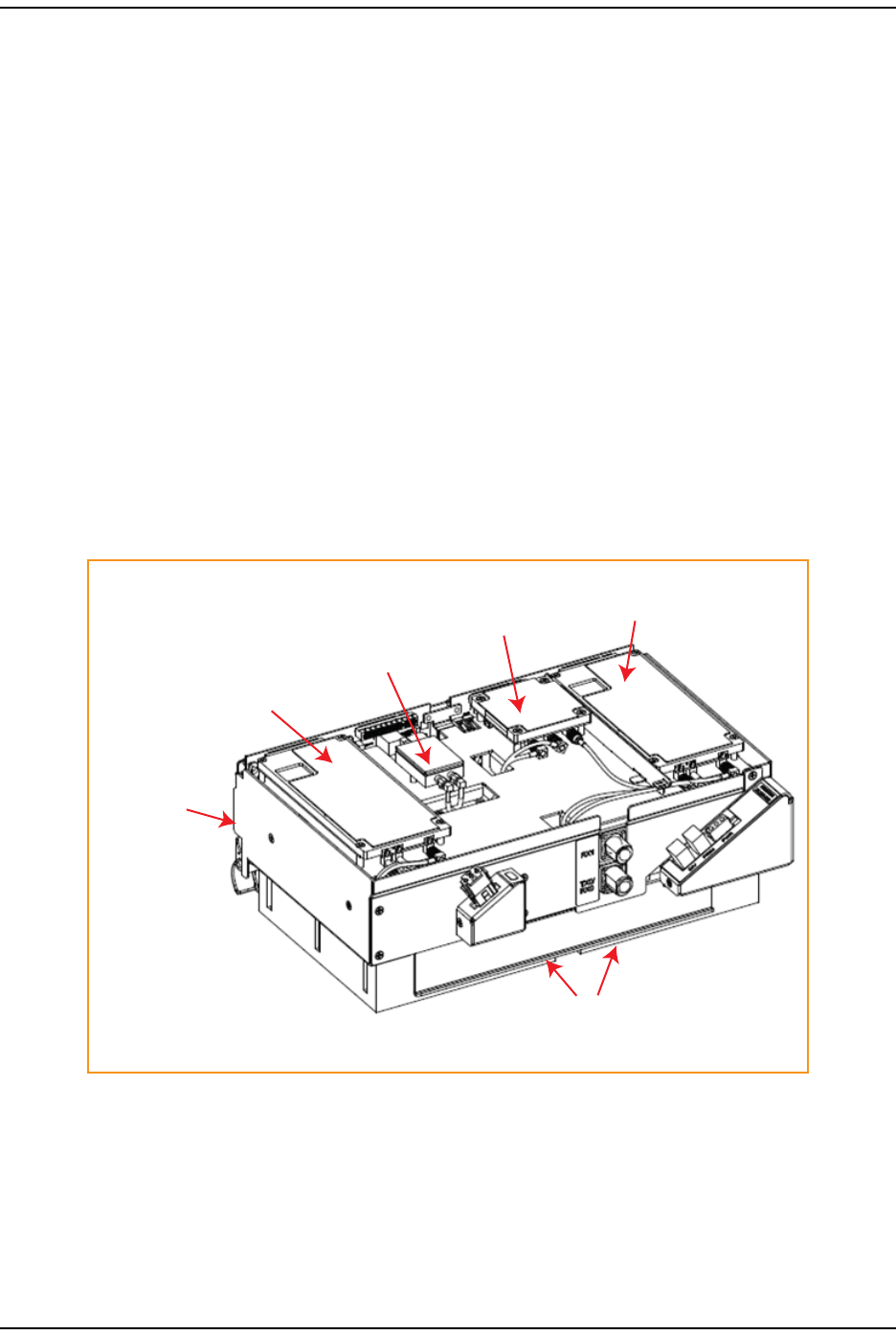
3Removereleaseliners,ifpresent,fromthethermalpadsontheRFModulepriortoinstalling
themoduleintothePRUchassis.
CAUTION! Thethermalpadsareverysensitivetomishandling—donotnick,scratch,ordingthem.
FormostRFModules,thethermalpadsarelocatedaslistedbelowandasshowninFigure9,
whichshowsaDual‐Slot40WRFModule.
•onelargepadonthebacksurfaceofeachLinearPowerAmplifier(LPA)
•uptotwoonthefrontsurface(DARTs)
•oneontheleftsideforthe(RDI)
•oneonthevectormodulatorboard
One large
thermal pad on each PA
(bottom of the LPA)
One thermal pad
for the RDI
One thermal pad
for each DART
One thermal pad
for each DART
One thermal pad
for RF Power
Combiner
One thermal pad
for Vector
Modulator
•oneontheRFpowercombiner.
Figure9.Thermal Pads on a Dual-Slot 40W RF Module
Install the RF Module(s)
Page 22 FlexWave Prism RF Modules for Prism Remote Units Installation Guide
© 2012 TE Connectivity Ltd TECP-77-141 • Issue 1 • April 2012
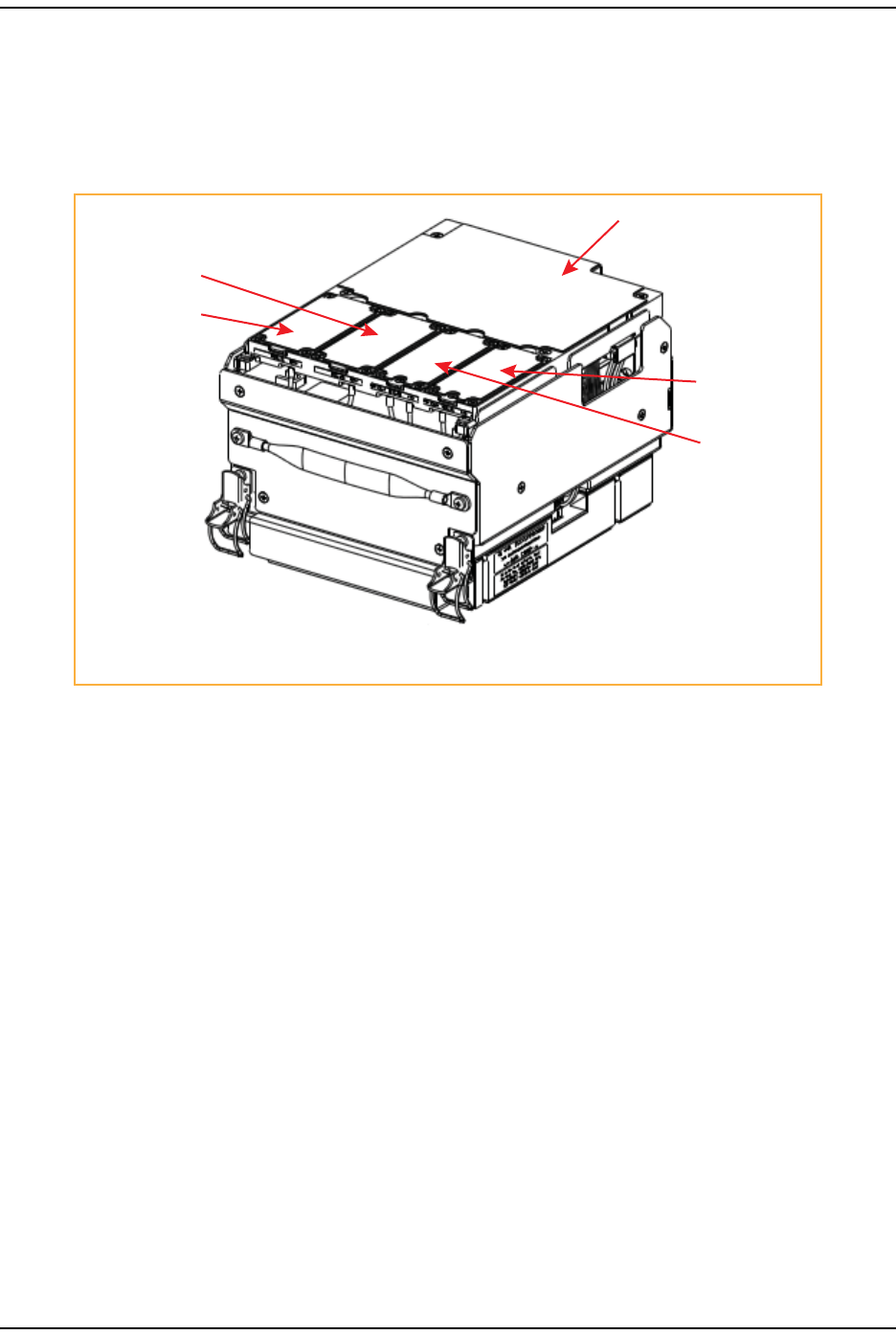
ForHDMRFModules,thethermalpadsarelocatedaslistedbelowandasshowninFigure10.
•onepadforeachRxandTxboard
•onelargepadovertheDPM
•oneforeachPowerAmplifier(PA),whichisonthebottomoftheHDMRFModule.
DPM Thermal Pad
Tx A Thermal Pad
Tx B Thermal Pad
Rx A Thermal Pad
Rx B Thermal Pad
2.9796 in2.9796 in
NOTE: Tx and Rx cards are paired: Tx A ony pairs with Rx A and Tx B only pairs with Rx B.
Figure10.Thermal Pads on an HDM RF Module
Dual-Slot Modules Only—Remove the Module Slot Shelf
FlexWave Prism RF Modules for Prism Remote Units Installation Guide Page 23
TECP-77-141 • Issue 1 • April 2012 © 2012 TE Connectivity Ltd.
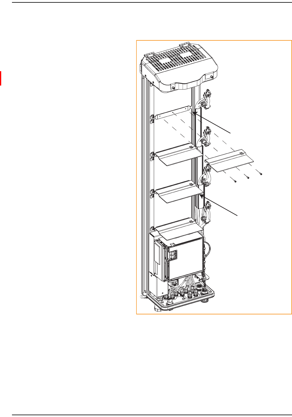
Dual‐SlotModulesOnly—RemovetheModuleSlotShelf
4ForDual‐SlotRFModulesonly.
Use 9/64” Allen Wrench to
remove the three module-shelf screws
Remove Module D Shelf for
Dual-Band Dual-Slot RF Modules
Remove Module B Shelf for
Dual-Slot 40W RF Modules
IfyouareinstallingaDual‐SlotRF
Module,youmustremoveamodule
slotshelffromthePRUchassisto
accommodatethemodule’ssize.
(Forfurtherinformation,Table6
onpage11.)
Removetheshelfasappropriatefor
theRFModule:
•ForaDual‐Slot40WRFModule,
removetheModuleBShelf.
•ForaDual‐BandDual‐SlotRF
Module,removeModuleD
Shelf.
Toremovethemoduleshelf:
aUsea9/64”Allen™wrenchto
removethethreescrewsthat
attachthemoduleshelftothe
PRUchassis,asshowninthe
followinggraphic.
bDiscardorstorethemodule
shelfandfasteners.

Install the RF Module(s)
Page 24 FlexWave Prism RF Modules for Prism Remote Units Installation Guide
© 2012 TE Connectivity Ltd TECP-77-141 • Issue 1 • April 2012
InstalltheRFModuleintothePrismRemoteChassis
Recommendation: InstallDual‐BandDual‐Slotmodulesinthetwoupper‐mostslotsofthePRU.
Recommendation: InstallDual‐Slot40Wmodulesinthebottom‐mostslotsofthePRU.
Recommendation: IfbothaDual‐SlotAWS210040WRFModuleandaDual‐SlotPCS190040W
RFModuleareinstalledinaQuad‐BandPRU,installtheAWS2100Modulein
thelower‐mostslotofthePRU.
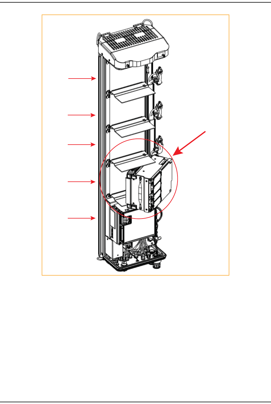
5HoldtheRFModulesothattheDARTcard(s)faceawayfromthePRUandtheMountingHook
istowardtheReceivingflangeonthePRUchassis.
NOTE: AlwaysinstallRFModulesfromthebottomup.Donotskipaslot.
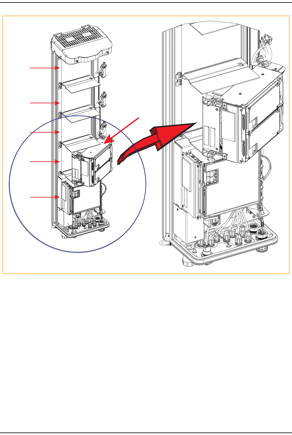
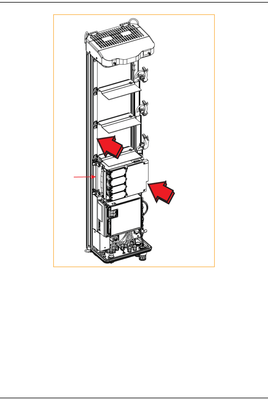
6HoldingtheRFModuleata45°angleinrespecttotherearheatsink,restthebottomsurface
ofthemoduleontheRFModuleshelf,asshowninoneofthefollowinggraphics,andas
applicabletotheRFModule.
•Single‐SlotRFModule:Figure11onpage25
•HDMRFModule:Figure12onpage26
•Dual‐BandDual‐SlotRFModule:Figure13onPage27
•Dual‐Slot40WRFModule:Figure14onPage28.
RF MOD C
RF MOD D
SeRF
Module
RF MOD A
RF MOD B
Single-Slot
RF Module
Heat Sink
Install the RF Module into the Prism Remote Chassis
FlexWave Prism RF Modules for Prism Remote Units Installation Guide Page 25
TECP-77-141 • Issue 1 • April 2012 © 2012 TE Connectivity Ltd.
Figure11.Installing a Single-Slot RF Module
RF MOD C
RF MOD D
SeRF
Module
RF MOD A
RF MOD B
HDM RF Module
Install the RF Module(s)
Page 26 FlexWave Prism RF Modules for Prism Remote Units Installation Guide
© 2012 TE Connectivity Ltd TECP-77-141 • Issue 1 • April 2012
Figure12.Installing an HDM RF Module
Installing a Dual-Band
Dual-Slot RF Module
Install the RF Module into the Prism Remote Chassis
FlexWave Prism RF Modules for Prism Remote Units Installation Guide Page 27
TECP-77-141 • Issue 1 • April 2012 © 2012 TE Connectivity Ltd.
Figure13.Installing a Dual-Band Dual-Slot RF Module
Install the RF Module(s)
Page 28 FlexWave Prism RF Modules for Prism Remote Units Installation Guide
© 2012 TE Connectivity Ltd TECP-77-141 • Issue 1 • April 2012
Figure14.Installing a Dual-Slot 40W RF Module
Install the RF Module into the Prism Remote Chassis
FlexWave Prism RF Modules for Prism Remote Units Installation Guide Page 29
TECP-77-141 • Issue 1 • April 2012 © 2012 TE Connectivity Ltd.
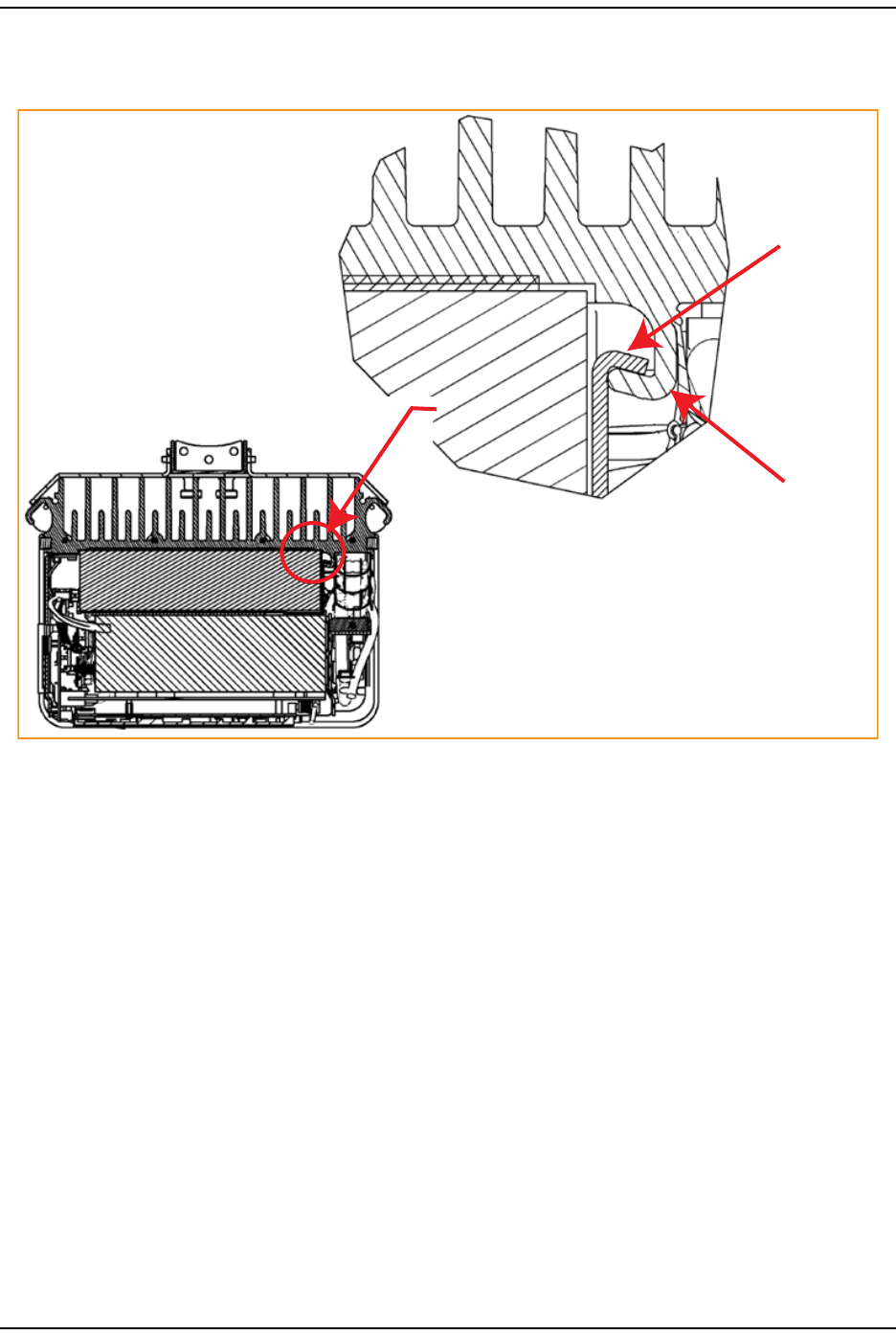
7AligntheMountingHookonthemodulewiththereceivingflangeonthePRUheatsink,and
thenslidetheRFModuleintowardtheflangeuntilitcangonofurther.
RF Module
Mounting hook
Chassis
Receiving
flange
Install the RF Module(s)
Page 30 FlexWave Prism RF Modules for Prism Remote Units Installation Guide
© 2012 TE Connectivity Ltd TECP-77-141 • Issue 1 • April 2012
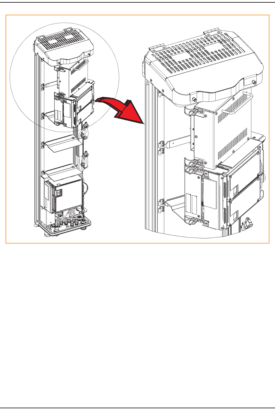
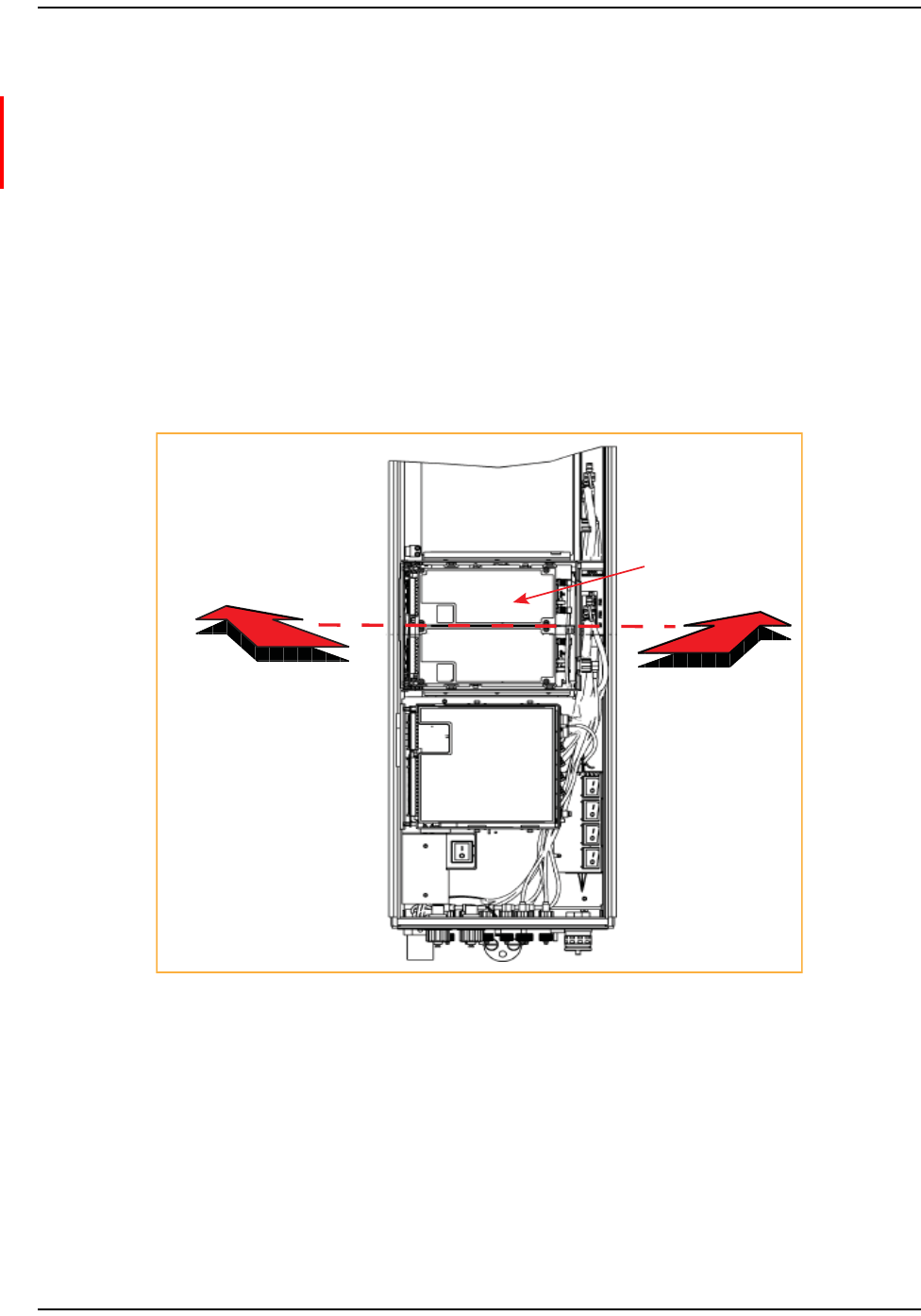
8PushtheleftedgeoftheRFModulebackandintothePRUchassisuntilitcangonofurther,as
showninthefollowinggraphics:
•ForSingle‐SlotRFmodules,seeFigure15onpage30.
•ForHDMRFmodules,seeFigure16onpage31.
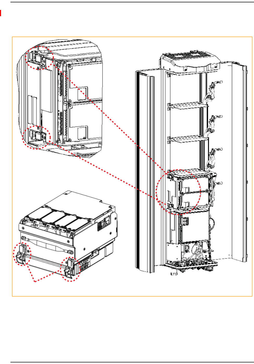
•ForDual‐SlotRFmodules,seeFigure17onpage32,whichusestheDual‐Slot40WRF
Moduleasanexample.
CAUTION! MakesuretheRFModuleisseatedcorrectlyintheModuleshelf.IncorrectalignmentoftheRF
ModulecancausetheRFModuletofailduetooverheating.
•ThefrontedgeoftheRFModuleshouldbeparallelwiththeshelfaboveit.
•TheMountingHookontheRFModuleshouldbefullyengagedwiththeReceivingflangeon
thePRUchassis.
•IfyoulatercannotshutthePRUdoor,verifythattheRFModuleisinstalledcorrectly.
Push the RF Module
back into the chassis
until it can go no further.
Single-Slot
RF Module
Figure15.Seating a Single-Slot RF Module
Push the HDM RF Module
back into the chassis
until it can go no further.
HDM
RF Module
Install the RF Module into the Prism Remote Chassis
FlexWave Prism RF Modules for Prism Remote Units Installation Guide Page 31
TECP-77-141 • Issue 1 • April 2012 © 2012 TE Connectivity Ltd.
Figure16.Seating an HDM RF Module
Push the RF Module back
into the chassis until it can
go no further.
Install the RF Module(s)
Page 32 FlexWave Prism RF Modules for Prism Remote Units Installation Guide
© 2012 TE Connectivity Ltd TECP-77-141 • Issue 1 • April 2012
Figure17.Seating a Dual-Slot RF Module
SecureRFModuleLatches
9TosecurethemodulelatchesontheleftsideoftheRFModule,dooneofthefollowing,as
appropriatefortheRFModulebeinginstalled:
•“ConnectLatchesonSingle‐SlotandHDMRFModules”onpage33
•“ConnectLatchesonDual‐BandDual‐SlotRFModules”onpage34.
Secure RF Module Latches
FlexWave Prism RF Modules for Prism Remote Units Installation Guide Page 33
TECP-77-141 • Issue 1 • April 2012 © 2012 TE Connectivity Ltd.
ConnectLatchesonSingle‐SlotandHDMRFModules
ForSingle‐SlotandHDMRFModules,securetwolatches,asshowninFigure18.
Two latches on Single-Slot
RF Modules
Two latches on
HDM RF Modules
Figure18.Latches on Single-Slot and HDM RF Modules
Install the RF Module(s)
Page 34 FlexWave Prism RF Modules for Prism Remote Units Installation Guide
© 2012 TE Connectivity Ltd TECP-77-141 • Issue 1 • April 2012
ConnectLatchesonDual‐BandDual‐SlotRFModules
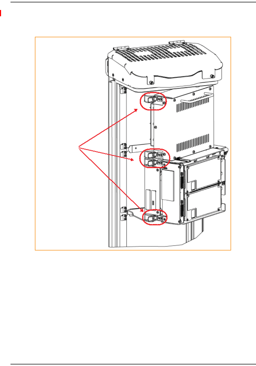
ForDual‐BandDual‐SlotRFModules,securefourlatches,asshowninFigure19.
Four latches in a
Dual-Band Dual-Slot
RF Module
Figure19.Dual-Band Dual-Slot RF Module Latches
Secure RF Module Latches
FlexWave Prism RF Modules for Prism Remote Units Installation Guide Page 35
TECP-77-141 • Issue 1 • April 2012 © 2012 TE Connectivity Ltd.
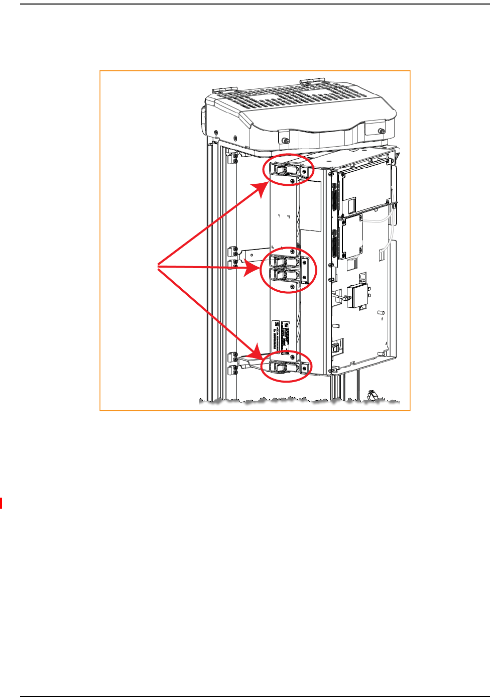
LatchesonDual‐Slot40WRFModules
ForDual‐Slot40WRFModules,securefourlatches,asshowninFigure20.
Four latches
in a Dual-Slot
40W RF Module
Figure20.Dual-Slot 40W RF Module Latches
VerifythattheRFModuleMountingHookisEngaged
10 VerifythattheRFModuleMountingHookisengagedcorrectlybypullingthemoduleaway
fromtheheatsink.TheRFModuleshouldnotmove.IftheRFModulemovesduringthischeck,
repeatStep6onpage24throughStep9.

Install the RF Module(s)
Page 36 FlexWave Prism RF Modules for Prism Remote Units Installation Guide
© 2012 TE Connectivity Ltd TECP-77-141 • Issue 1 • April 2012
ConnecttheRFModuleCables
11 PositionthecablessothattheyareundertherightedgeoftheRFModule,pointingup.
12 FollowtheruleslistedbelowwhenconnectingtheRFModulecables.
•AlwaysprovidedateachRFModuleshelfarefivecables:
–onePower(PWR)cable
–twoRFcables(TX0/RX0)and(TX1/RX1)
–twohigh‐speed‐datacables,whichinthisdocumentarereferredtoasLow‐Voltage
DifferentialSignaling(LVDS)cables.
•LVDScableslabeledPRIMandDIVshouldalwayseitherbeconnectedorstrainrelievedto
adjacentcables.Thisprotectsagainstthecablegettingcaughtinthechassisdoor.
•MakesurethetwoLVDScablesarefullyseatedandlockedintotheirconnectors.
•IfyouareinstallingamoduleintoaDiversityChassis,bothRFcableslabeledMODN
TX0/RX0andMODNTX1/RX1willbepopulated.
•ForDiversitymodules,allcablesaretobeconnected.
•WhenyouorderaDualSuperDARTmodule,connectbothLVDScables(PRIMandDIV)and
theRFTX0/RX0cable.
•Adheretoaminimumbendradiusof1‐inchforallRFcablesfromtheintegratedcable
guidetothemodule.
•Maintainadequatestrainreliefdistancesfromconnectionpointstothemodule.
•WheninstallingDual‐SlotRFmodules:
–TheupperRFModuleshelfwilleithernotbepresent(factoryinstalledmodule)orwill
beremovedpriortoinstallation(fieldinstalledmodule).
–ForDual‐Slotmodules,onlytheRFcablelabeledMODNTX0/RX0onthelowermodule
slotwillbeconnectedtothemoduleconnectorTX0/RX0.
–TheMODNTX1/RX1cableshouldbesecuredtothecablebundleusingtheprovided
cabletie.
–EnsurethattheMODNTX1/RX1cableandconnectoraresecuredsothattheywillnot
bepinchedorpreventthePRUdoorfromclosing.
–ThePower(PWR)cableandtwoLVDScablesoftheupperRFModuleslotwillnotbe
used.ConnecttheRFcablelabeledMODNTX1/RX1totheconnectorlabeledN/Conthe
upperhalfofthedouble‐slotmodule.Useoneoftheprovidedcabletiestosecurethe
MODNTX0/RX0RFcable,bothLVDScablesandthePower(PWR)cabletotheRFcable
labeledMODNTX1/RX1,ensuringthatthecablebundlewillnotbepinchedorprevent
thePRUdoorfromclosing.

Connect the RF Module Cables
FlexWave Prism RF Modules for Prism Remote Units Installation Guide Page 37
TECP-77-141 • Issue 1 • April 2012 © 2012 TE Connectivity Ltd.
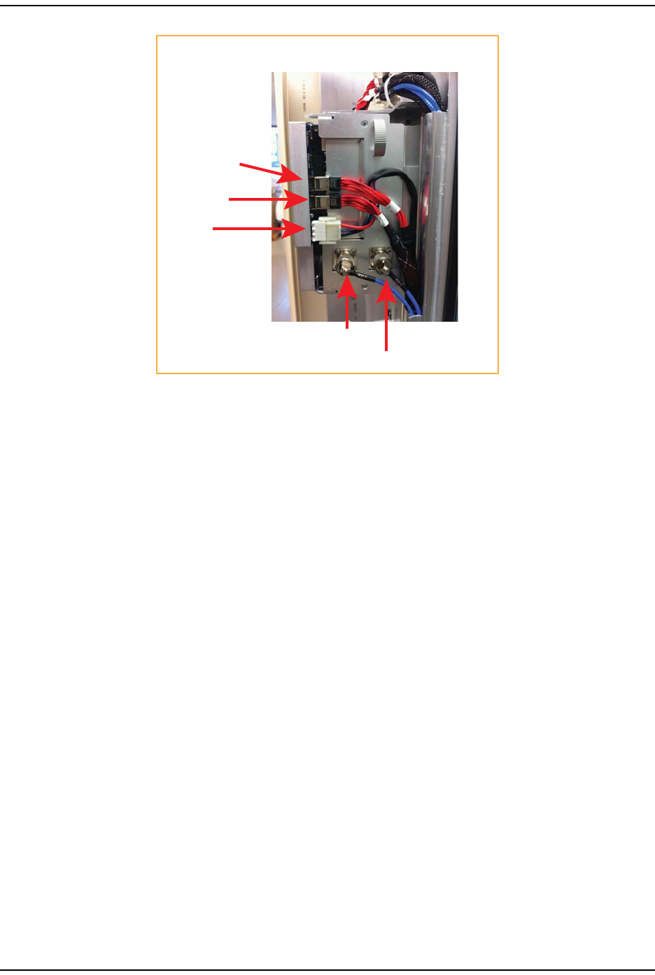
13 Workingfromthebottomconnectorup,connecttheRFModulecables.
aIfthisisaDiversitychassis:
•ForSingle‐Slotinstallationsonly—connecttheRFDiversitycablelabeledMODN
TX1/RX1totheTX1/RX1connectorandturnthethumbscrewtosecurethecabletothe
chassis.
•ForDual‐Slotinstallationsonly—theTX1/RX1connectorispre‐populated.Donot
removethefactoryconnectiontoRX1.Instead,securetheMODNTX1/RX1cabletothe
cablebundleusingoneoftheprovidedcableties.EnsurethattheMODNTX1/RX1cable
andconnectoraresecuredsotheywillnotbepinchedorpreventthedoorfrom
closing.
bConnecttheRFcablelabeledMODNTX0/RX0totheTX0/RX0connectorandturnthe
thumbscrewtosecurethecabletothechassis.
cForSingle‐Slotinstallationsonly—connecttheMODNDIVLVDScabletotheDIV
connector.ThisconnectstheRemoteUnitSeRF(RSI)interfaceboardtotheDiversity
DART.MakesurethatyouheartheLVDScablelockintotheDIVconnectorwithanaudible
click.GiveagentletugontheLVDScable—ifyoudonotpresstheunlocklever,theLVDS
cableshouldnotcomeoutoftheconnector.
NOTE: AlwaysconnecttheDiversityLVDScable.Thispreventsthecablefromgettingcaughtbetween
thechassisdoorandtheRFModule.
dConnecttheMODNPRIMLVDScabletothePRIMconnector.ThisconnectstheRSItothe
PrimaryDART.
eConnectthePowercabletothePWRconnector.ThisconnectstheRFModuletotheDC
powerconnection.
fForDual‐Slotinstallationsonly—thePower(PWR)cableandtwoLVDScablesofthe
upperRFModuleshelfarenotbeused.ConnecttheRFcablelabeledMODNTX1/RX1ofthe
upperRFModuleshelftotheconnectorlabeledN/ContheupperhalfoftheDual‐Slot
module.UseoneoftheprovidedcabletiestosecuretheMODNTX0/RX0RFcable,both
LVDScablesandthePower(PWR)cabletotheRFcablelabeledMODNTX1/RX1,ensuring
thatthecablebundlewillnotbepinchedorpreventthePRUdoorfromclosing.
RefertothegraphicthatcorrespondstotheRFModulebeinginstalled:
•Single‐SlotRFModule:Figure21onPage38
•HDMRFModule:Figure22onpage39
•Dual‐BandDual‐SlotRFModule:Figure23onPage40
•Dual‐Slot40WRFModule:Figure24onPage41.
MOD A
MOD D
MOD C
MOD B
SeRF
Module
TX0/RX0
RX1
DIV
PRIM
PWR
Note routing of
high-speed cables
Note bend
radii ≥ 1-inch
Edge of Connector Interface Panel
Cable connections for a Single-Slot RF Module
Install the RF Module(s)
Page 38 FlexWave Prism RF Modules for Prism Remote Units Installation Guide
© 2012 TE Connectivity Ltd TECP-77-141 • Issue 1 • April 2012
Figure21.Cable Connections for Single-Slot RF Modules
Cable connections for an HDM RF Module
TX0/RX0
TX1/RX1
POWER
DATA 1 (DIV)
DATA 0 (PRIM)
Connect the RF Module Cables
FlexWave Prism RF Modules for Prism Remote Units Installation Guide Page 39
TECP-77-141 • Issue 1 • April 2012 © 2012 TE Connectivity Ltd.
Figure22.Cable Connections for HDM RF Modules
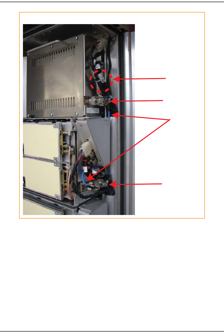
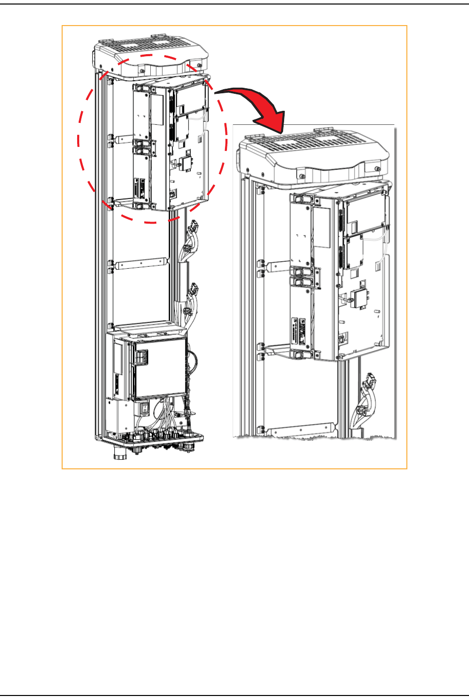
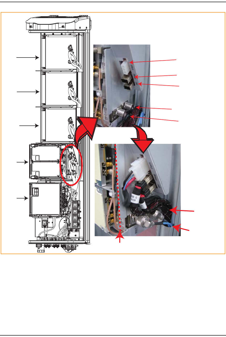
Cable Connections for a Dual-Slot RF Module
Tie wrap
Factory-installed
RX1 cable
Two N-Type
RF connectors
Two N-Type
RF connectors
Install the RF Module(s)
Page 40 FlexWave Prism RF Modules for Prism Remote Units Installation Guide
© 2012 TE Connectivity Ltd TECP-77-141 • Issue 1 • April 2012
Figure23.Cable Connections for Dual-Band Dual-Slot RF Modules
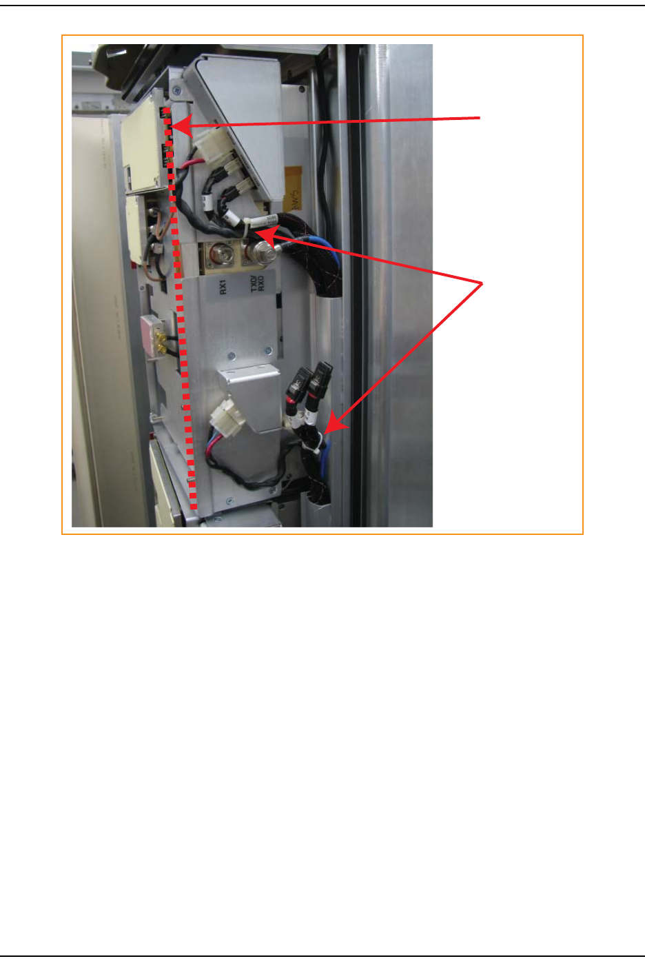
Tie wrap around
factory-installed
RX1 cable
Keep cable bends
behind the edge
of the Connector
Interface Panel
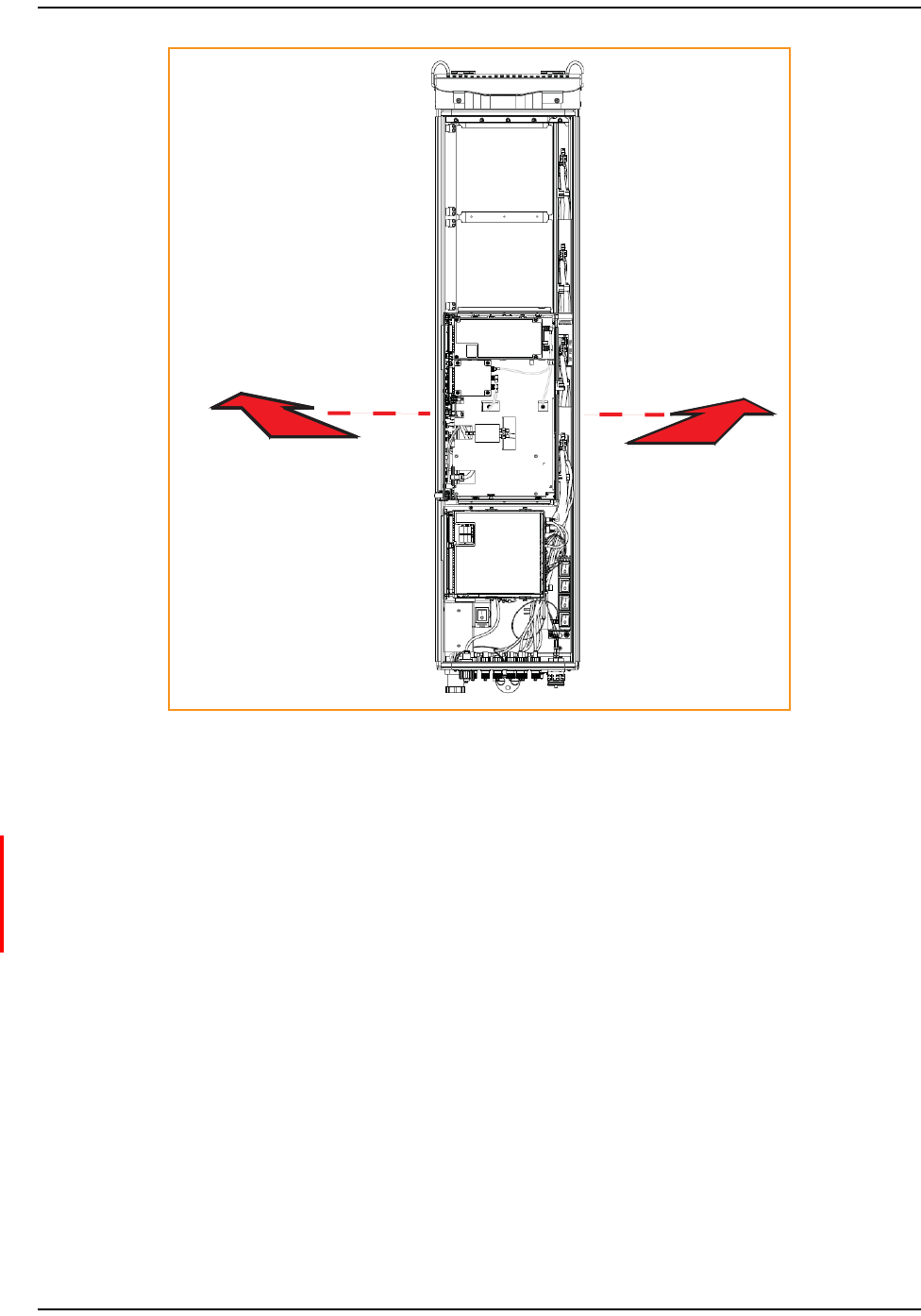
Connect the RF Module Cables
FlexWave Prism RF Modules for Prism Remote Units Installation Guide Page 41
TECP-77-141 • Issue 1 • April 2012 © 2012 TE Connectivity Ltd.
Figure24.Cable Connections for Dual-Slot 40W RF Modules
14 EnsurethatallcablebendsarebelowthetopedgeoftheConnectorInterfacePanelas
indicatedbythedashedlineintheprecedingfigure.Failuretocorrectlypositionthecables
couldinhibitclosingthePRUdoor,whichcanresultindamagetothecables.
Install the RF Module(s)
Page 42 FlexWave Prism RF Modules for Prism Remote Units Installation Guide
© 2012 TE Connectivity Ltd TECP-77-141 • Issue 1 • April 2012
PowerontheRFModule
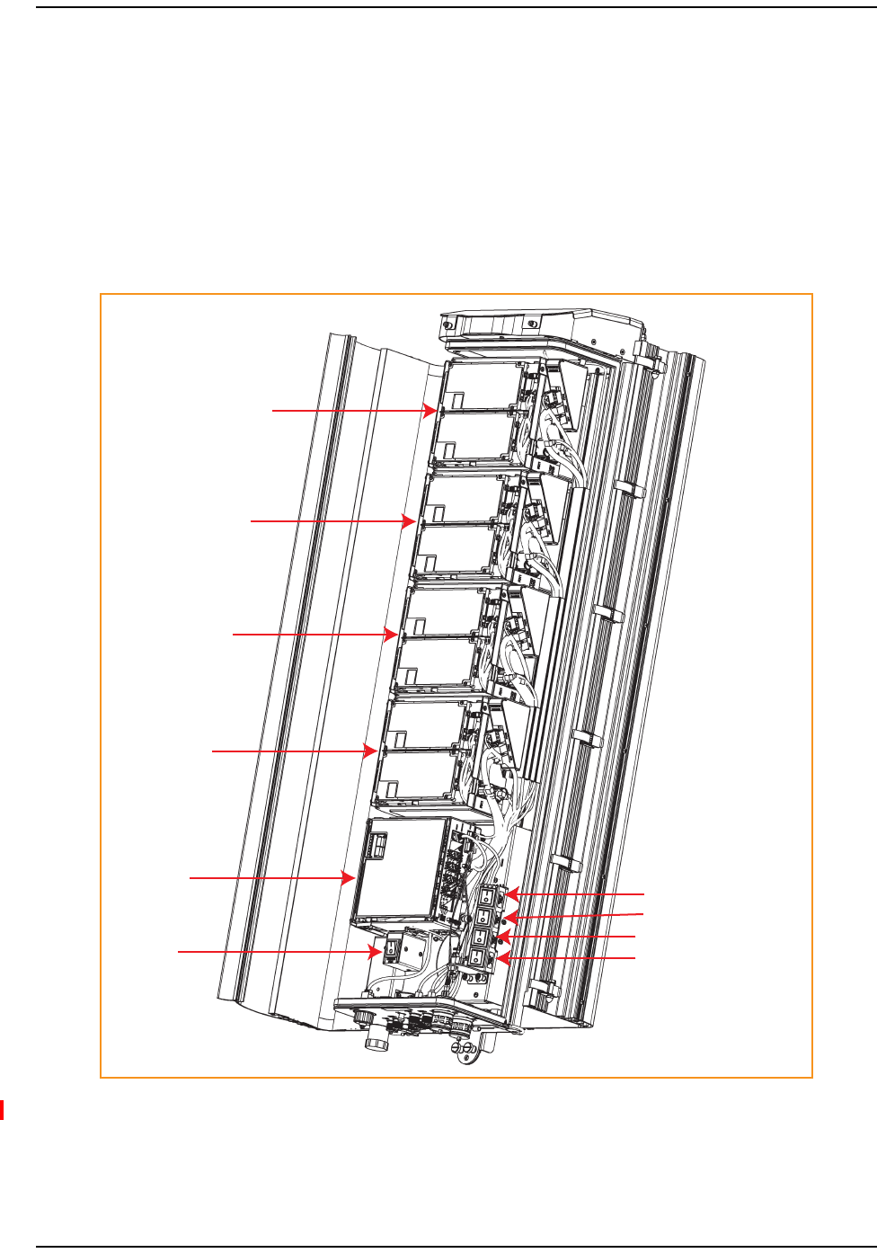
15 FollowtheruleslistedbelowtotogglethePowerswitchthatcorrespondstotheRFModule
toitsONposition.
•ForDual‐SlotRFModules,usethePowerswitchforthelowermodule.Forexample,to
powerupaDual‐SlotRFModuleincombinedslotsC+DinaQuad‐Bandchassis,turnON
DCPowerswitchforModC;leavetheDCPowerswitchforModDOFF.
•ADual‐Slot40WRFModuleusesthePowerSuppliesinbothslots.IftheDual‐Slot40WRF
ModuleisinstalledinslotsC+D,turnONthePowerswitchforModCandModD.
MOD A
SeRF
Module
AC Power
switch for
Remote
chassis
DC Power switch for Mod A
DC Power switch for Mod B
DC Power switch for Mod C
DC Power switch for Mod D
MOD B
MOD C
MOD D
16 RepeatStep1throughStep15toinstallotherRFModules.

Contacting TE Connectivity by Telephone
FlexWave Prism RF Modules for Prism Remote Units Installation Guide Page 43
TECP-77-141 • Issue 1 • April 2012 © 2012 TE Connectivity Ltd.
CONTACTINGTECONNECTIVITY
ContactingTEConnectivitybyTelephone
Sales
Asia Pacific +65-6294-9948
France 0800 914032
Germany 0180 2232923
Italy 0800 782374
Spain 900 983291
United Kingdom 0800 960236
USA or Canada 1-800-366-3891
Extension 73000
Connectivity Extension 73475
Wireless Extension 73476
Technical Support
USA or Canada 1-800-530-9960
Elsewhere +1-952-917-0761
OnlineAccesstoTEConnectivity
Customer Portal
https://www.te.com/commerce/uso/myaccount.do
Technical Support for Wireless Products
http://www.te.com/WirelessSupport

Contacting TE Connectivity
Page 44 FlexWave Prism RF Modules for Prism Remote Units Installation Guide
© 2012 TE Connectivity Ltd TECP-77-141 • Issue 1 • April 2012