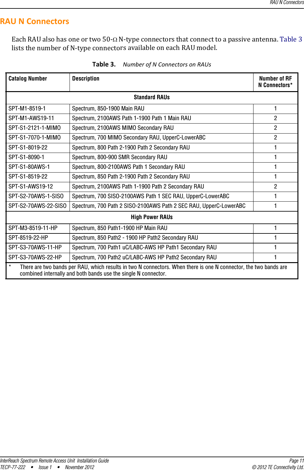
ADC Telecommunications S2191-011 The main function is to retransmits signals from and to the mobiles. User Manual InterReach Spectrum Remote Access Unit Installation Guide
ADC Telecommunications Inc. The main function is to retransmits signals from and to the mobiles. InterReach Spectrum Remote Access Unit Installation Guide
FCC RE0.6 MANUAL_Spectrum_RAU_Installation_Guide_FCC
![TECP-77-222 Issue 1 November 2012300001759666 Rev AMain Remote Access UnitSecondary Remote Access UnitInterReach Spectrum™ Remote Access Unit Installation Guide](https://usermanual.wiki/ADC-Telecommunications/S2191-011/User-Guide-1881965-Page-1.png)
![Copyright© 2012 TE Connectivity, Inc. All Rights Reserved.Information contained in this document is company private to TE Connectivity Ltd., and shall not be modified, used, copied, reproduced or disclosed in whole or in part without the written consent of TE.Trademark InformationFlexWave, FlexWave Prism, InterReach Spectrum, Universal Radio Head, TE Connectivity, and TE connectivity (logo) are trademarks.All other logos, products and/or company names referred to herein might be trademarks of their respective owners. Disclaimer of LiabilityContents herein are current as of the date of publication. TE reserves the right to change the contents without prior notice. Should the content of printed user documentation shipped with product differ from documentation provided on a product CD (inclusive of the associated Help modules), the printed user documentation supersedes the documentation on the product CD. In no event shall TE be liable for any damages resulting from loss of data, loss of use, or loss of profits, and TE further disclaims any and all liability for indirect, incidental, special, consequential or other similar damages. This disclaimer of liability applies to all products, publications and services during and after the warranty period.Specific Disclaimer for High-Risk ActivitiesThis Product is not specifically designed, manufactured, tested or intended for use in high-risk activities including, without restricting the generality of the foregoing, on-line control of aircraft, air traffic, aircraft navigation or aircraft communications; or in the design, construction, operation or maintenance of any nuclear facility. TE (including its affiliates) and its suppliers specifically disclaim any express or implied warranty of fitness for such purposes or any other purposes.Screenshots in User DocumentationDue to concurrent development of this documentation, artwork, and the InterReach Spectrum Element Management System (EMS), there may be some minor discrepancies between screenshots contained in this documentation and those actually displayed in the InterReach Spectrum EMS. These discrepancies will generally be few and minor and should not affect your understanding of InterReach Spectrum EMS.](https://usermanual.wiki/ADC-Telecommunications/S2191-011/User-Guide-1881965-Page-2.png)
![InterReach Spectrum Remote Access Unit Installation Guide Page 1TECP-77-222 • Issue 1 • November 2012 ©2012 TE Connectivity Ltd.TABLEOFCONTENTSTopics PagePreface .................................................................................................................................................................2InterReachSpectrumUserDocumentation ........................................................................................................... 2AccessingUserDocumentationontheTECustomerPortal...............................................................................................3DocumentCautionsandNotes...........................................................................................................................................3StandardsCertification........................................................................................................................................... 4ProductOverview.................................................................................................................................................5MainRemoteAccessUnits..................................................................................................................................... 7MRAUPorts,Cable,andConnectors ..................................................................................................................................7MRAULEDs .........................................................................................................................................................................8SecondaryRemoteAccessUnits ............................................................................................................................ 9SRAUPorts,Cable,andConnectors....................................................................................................................................9SRAULEDs.........................................................................................................................................................................10RAUNConnectors................................................................................................................................................ 11InstalltheRAUsandAntennas............................................................................................................................12MounttheRAUsandAntennas............................................................................................................................ 12GeneralSafetyPrecautions .................................................................................................................................. 12ConnecttheIFEUtotheMRAU............................................................................................................................14ConnecttheMRAUtoSRAUs ............................................................................................................................... 16ConfiguretheMRAUsandSRAUs......................................................................................................................... 18AppendixA:Specifications..................................................................................................................................19RemoteAccessUnitSpecifications ...................................................................................................................... 19SpectrumSystemSpecifications........................................................................................................................... 19CompositePowerOutofRAU .............................................................................................................................. 21AppendixB:75‐OhmCATVCable........................................................................................................................24CATVCableRequirements.................................................................................................................................... 24Belden1695ACoaxSpecifications ....................................................................................................................... 25Description .......................................................................................................................................................................25OverallPhysicalCharacteristics ........................................................................................................................................25OverallNominalElectricalCharacteristics........................................................................................................................26Belden7732ACoaxSpecifications ....................................................................................................................... 27Description .......................................................................................................................................................................27OverallPhysicalCharacteristics ........................................................................................................................................27OverallNominalElectricalCharacteristics........................................................................................................................28AppendixC:OmniAntenna.................................................................................................................................29AppendixD:ContactingTEConnectivity .............................................................................................................30ContactingTEConnectivitybyTelephone............................................................................................................ 30OnlineAccesstoTEConnectivity ......................................................................................................................... 30](https://usermanual.wiki/ADC-Telecommunications/S2191-011/User-Guide-1881965-Page-3.png)
![Preface Page 2 InterReach Spectrum Remote Access Unit Installation Guide© 2012 TE Connectivity Ltd TECP-77-222 • Issue 1 • November 2012PREFACEThismanualprovidesinstallationinstructionsforInterReachSpectrum®RemoteAccessUnits(RAUs).Table1liststhestandardRAUsthataresupportedinthisdocument.Table1.SupportedSpectrumStandardRemoteAccessUnitsCatalog Number DescriptionStandard RAUsSPT-M1-8519-1 Spectrum, 850-1900 Main RAUSPT-S1-8519-22 Spectrum, 850 Path 2-1900 Path 2 Secondary RAUSPT-S1-8090-1 Spectrum, 800-900 SMR Secondary RAUSPT-S1-80AWS-1 Spectrum, 800-2100AWS Path 1 Secondary RAUSPT-S1-8019-22 Spectrum, 800 Path 2-1900 Path 2 Secondary RAUSPT-S2-70AWS-1-SISO Spectrum, 700 SISO-2100AWS Path 1 SEC RAU, UpperC-LowerABCSPT-S2-70AWS-22-SISO Spectrum, 700 Path 2 SISO-2100AWS Path 2 SEC RAU, UpperC-LowerABCSPT-S1-7070-1-MIMO Spectrum, 700 MIMO Secondary RAU, UpperC-LowerABC SPT-M1-AWS19-11 Spectrum, 2100AWS Path 1-1900 Path 1 Main RAU SPT-S1-AWS19-12 Spectrum, 2100AWS Path 1-1900 Path 2 Secondary RAU SPT-S1-2121-1-MIMO Spectrum, 2100AWS MIMO Secondary RAUHigh Power RAUsSPT-M3-8519-11-HP Spectrum, 850 Path1-1900 HP Main RAUSPT-S3-8519-22-HP Spectrum, 850 Path2 - 1900 HP Path2 Secondary RAUSPT-S3-70AWS-11-HP Spectrum, 700 Path1 uC/LABC-AWS HP Path1 Secondary RAUSPT-S3-70AWS-22-HP Spectrum, 700 Path2 uC/LABC-AWS HP Path2 Secondary RAUInterReachSpectrumUserDocumentationTheInterReachSpectrumuserdocumentationisintendedforsystemadministrators,engineersandinstallersresponsibleforplanning,administering,configuring,andmaintainingTEConnectivityInterReachSpectrumsystems.Table1liststhemanualsthatcorrespondtothisInterReachSpectrumrelease.Table2.InterReachSpectrumUserDocumentationTitle TECP Number InterReachSpectrumElementManagementSystem8.1UserManual TECP-77-215InterReachSpectrumHostUnitInstallationGuide TECP-77-220InterReachSpectrumExpansionModuleGroupInstallationGuide TECP-77-221InterReachSpectrumRemoteAccessUnitInstallationGuide TECP-77-222FlexWavePrismOADMSpliceBoxInstallationGuide TECP-77-208](https://usermanual.wiki/ADC-Telecommunications/S2191-011/User-Guide-1881965-Page-4.png)
![InterReach Spectrum User DocumentationInterReach Spectrum Remote Access Unit Installation Guide Page 3TECP-77-222 • Issue 1 • November 2012 © 2012 TE Connectivity Ltd.AccessingUserDocumentationontheTECustomerPortalAccesstotheCustomerPortalrequiresauseraccountandpassword.Ifyoudonothaveanaccount,clickontheregistrationlinkontheLogInpage.1ClickonthefollowingURLlinkorentertheURLintoyourwebbrowser,andthenpressEnteronyourkeyboard:https://www.te.com/commerce/uso/myaccount.do2ClickMy Account > TE/Wireless Portal.3OntheCustomerPortalHomepage,clickManualsandDataSheets.4IntheManuals and Data Sheets Sectionspanel,clickontheproductnameofthedocumentyouneedtoaccess.5Clickonthetitleofthemanualthatyouneedtoopen/download.DocumentCautionsandNotesTwotypesofmessages,identifiedbelow,appearinthetext:CAUTION! Cautiontextindicatesoperationsorstepsthatcouldcausepersonalinjury,induceasafetyprobleminamanageddevice,destroyorcorruptinformation,orinterruptorstopservices.NOTE: Notetextcontainsinformationaboutspecialcircumstances.](https://usermanual.wiki/ADC-Telecommunications/S2191-011/User-Guide-1881965-Page-5.png)
![https://www.te.com/commerce/uso/myaccount.do">](https://usermanual.wiki/ADC-Telecommunications/S2191-011/User-Guide-1881965-Page-6.png)
![FCC: ThisequipmentcomplieswiththeapplicablesectionsofTitle47CFR,Part22(800MHzCellular),Part24(1900MHz‐PCS),Part90(800/900‐SMR),andPart27(700MHz,2100MHz‐AWS).Thisdevicecomplieswithpart15oftheFCCRules.Operationissubjecttotheconditionthatthisdevicedoesnotcauseharmfulinterference.NOTE: The U.S. Federal Communications Commission (FCC) has developed guidelines for evaluation of human exposure to RF emissions. The guidelines incorporate limits for Maximum Permissible Exposure (MPE) for power density of transmitter operating at frequencies between 300 kHz and 100 GHz. Limits have been set for portable, mobile, and fixed equipment. TE Connectivity products fall in the category of fixed equipment; products intended to be permanently secured and exposures are evaluated for distances greater than 40cm (15.75”). Portable devices fall into exposures of less than 20cm, where SAR evaluations are used. Antenna gain is restricted to 390mW ERP (. 8 30mW EIRP) in order to satisfy RF exposure compliance requirements. If higher than 38 5mW ERP, routine MPE evaluation is needed. The antennas should be installed to provide at least 40cm from all persons to satisfy MPE requirements of FCC Part 2, 2.1091. UL/CUL: Thiswillbeinstalledinarestrictedaccesslocation.Thisequipmentcomplies,perULandCUL50,StandardforEnclosuresforElectricalEquipment.UL/CUL: ThisequipmentcomplieswithULandCUL60950‐1StandardforSafetyforInformationTechnologyEquipment,includingElectricalBusinessEquipment.UL/CUL: AllInterReachSpectrumRAUsarePlenumratedandsuitableforuseinenvironmentalairspaceinaccordancewithSection300‐22(C)oftheNationalElectricalCode,andSections2‐128,12‐010(3)and12‐100oftheCanadianElectricalCode,Part1,CSAC22.1.UL: ThisequipmentisULPlenumratedunderUL2043.CAUTION! Modifications not expressly approved by the party responsible for compliance could void the user's authority to operate the equipment.](https://usermanual.wiki/ADC-Telecommunications/S2191-011/User-Guide-1881965-Page-7.png)
![Standards CertificationInterReach Spectrum Remote Access Unit Installation Guide Page 5TECP-77-222 • Issue 1 • November 2012 © 2012 TE Connectivity Ltd.PRODUCTOVERVIEWInterReachSpectrumsupportsupto8bandsinasinglesystem.Eachantennalocationsupportsthosebandsinmodular,grouppairings.EachlocationincludesaMainRemoteAccessUnit(MRAU)thatcanpoweruptothreeadditionalSecondaryRAUs(SRAUs),eachofwhichsupporttwopoweramplifierpairsforatotalofeightamplifiers.MRAUsandSRAUsaregroupedlogicallybasedoncommonserviceprovidergroupingsandinclude:850/1900,700/700MIMO,800/900SMR,700SISO/AWS,and800/AWS.AddingfrequencyisassimpleasplugginginanSRAUtotheexistingMRAU.RAUsareavailableintwodifferentoutputpoweroptions:StandardandHighPower.Thesecanbe“mixedandmatched”onasystemtomeetthespecificneedsofavenue.SinceSpectrumcanbeconfiguredtosupportasmanyasfourcascadedrunsofsixteentotalExpansionModuleGroups,thesystemconfigurationpossibilitiesareseeminglyendlessandcanscaletosinglesystemsthatincludeasmanyas128MRAUlocations,witheachofthoselocationssupportingbetweenoneandeightRFbands.Andeachofthosebandlocationsoffers26dBm(P1dB)or31dBm(P1dB)ofoutputpowerbasedonselectingstandardorHighPower(HP)RAUs.ThesystemmaybescaledtoaddnewbandsorRAUlocationsitesas‐neededandoffersgreatserviceflexibilityandperformancerelativetoshared,wide‐bandamplifiersystems.EachserviceprovidermaycontroltheirbandofinterestandenjoythepredictabilityinconsistentserviceateachRAUlocationindependentofwhatotheroperatorsaredoingorthelengththesignaltravelstotheservicearea.TheRAUsaretypicallymountedaboveceilingtilesorinout‐of‐sightlocationsascloseaspossibletotheservicearea.](https://usermanual.wiki/ADC-Telecommunications/S2191-011/User-Guide-1881965-Page-8.png)
![Product Overview Page 6 InterReach Spectrum Remote Access Unit Installation Guide© 2012 TE Connectivity Ltd TECP-77-222 • Issue 1 • November 2012Figure1illustrateshowRFandIFsignalsaresentbetweenSpectrumunitsandmodules.LINK STATUSSECONDARYREVSECONDARYFWDSECONDARYREVSECONDARYFWDLINK STATUSREV IF OUT REV SECONDARY PORTS 1 2 3FWD SECONDARY PORTS 1 2 3FWD IF INLINK STATUSHostSRAUMRAUPowerSupplyIFEUDRUIFRFOmniAntennaRFRFxx xxxx xxxx xxxxx xxxx xxxx xxxxREMOTESYSTEM IIIF DARTXXXXXXXXXXBW XX MHzFWDIF OUTREVIF INPWRSTATUSREMOTEIF DARTXXXXXXXXXXBW XX MHzFWDIF OUTREVIF INPWRSTATUSREMOTEIF DARTXXXXXXXXXXBW XX MHzFWDIF OUTREVIF INPWRSTATUSREMOTEIF DARTXXXXXXXXXXBW XX MHzFWDIF OUTREVIF INPWRSTATUSREMOTEIFIFHOSTSYSTEM IIRF DARTSMR900FWD 935-940REV 896-901REVRF OUTFWDRF INFWD NOT TOEXCEED +5 dBmPWRSTATUSHOSTRF DARTSMR900FWD 935-940REV 896-901REVRF OUTFWDRF INFWD NOT TOEXCEED +5 dBmPWRSTATUSHOSTRF DARTSMR900FWD 935-940REV 896-901REVRF OUTFWDRF INFWD NOT TOEXCEED +5 dBmPWRSTATUSHOSTRF DARTSMR900FWD 935-940REV 896-901REVRF OUTFWDRF INFWD NOT TOEXCEED +5 dBmPWRSTATUSHOSTNOTE: Units shown are not to scale.NOTE: AllFWDportsonallModulesarecolor‐codedredandallREVportsarecolor‐codedblue,whichmakestheDRU,IFEU,andRAUcablingprocesseasiertocomplete.Figure1.REV and FWD Signals for the RAUNOTE: ThisbookreferstotheOmniAntenna(4214‐M727),whichistheantennathatTEConnectivityrecommends.Otherantennasmaybeused.ForfurtherinformationontheOmniAntenna,see“AppendixC:OmniAntenna”onpage29.](https://usermanual.wiki/ADC-Telecommunications/S2191-011/User-Guide-1881965-Page-9.png)
![Main Remote Access UnitsInterReach Spectrum Remote Access Unit Installation Guide Page 7TECP-77-222 • Issue 1 • November 2012 © 2012 TE Connectivity Ltd.MainRemoteAccessUnitsTheMainRemoteAccessUnit(MRAU)receivesFWDIFsignalsfromanIFExpansionUnit(IFEU),whichispartoftheSpectrumExpansionModuleGroup,using75CATVcable.TheMRAUconvertstheIFsignalstoRFandsendsthemtoapassiveRFantennausing50coaxialcable.TheMRAUalsoreceivesconfigurationinformationandpowerfromandsendsitsstatusinformationtotheIFEU.TheMRAUreceivesREVRFsignalsfromapassiveRFantennausing50coaxialcable.ItconvertsthesignalstoIFandsendsthemtotheIFEUusing75CATVcable.MRAUPorts,Cable,andConnectorsREV IF OUT REV SECONDARY PORTS 1 2 3FWD SECONDARY PORTS 1 2 3FWD IF INLINK STATUS1 236 54Ref # Component Device Function1RF SubMiniature version A (SMA) cable (1)50 RF SMA-to-SMA cable Connects two RF bands together when there is only one N-type connector on the RAU.For cases when there is an N-type connector for each RF band (700MIMO or PCS/AWS), there will not be an SMA cable.2Antenna port(s) 50 N-type connector Connects to an antenna. See Table 3 on page 11.3FWD IF IN connector F connector port Connects to the IFEU FWD Module IF OUT connector via CATV cable.4FWD SECONDARY PORTS (1 - 3) F connector ports Connect to a SRAU SECONDARY FWD connector via CATV cable.5REV SECONDARY PORTS (1 - 3) F connector ports Connect to a SRAU SECONDARY REV connector via CATV cable.6REV IF OUT connector F connector port Connects to the IFEU REV Module IF IN connector via CATV cable.(1) The AWS/PCS MRAUs does NOT have an RF SMA cable, and has two Antenna ports.](https://usermanual.wiki/ADC-Telecommunications/S2191-011/User-Guide-1881965-Page-10.png)
![Product Overview Page 8 InterReach Spectrum Remote Access Unit Installation Guide© 2012 TE Connectivity Ltd TECP-77-222 • Issue 1 • November 2012MRAULEDsREV IF OUT REV SECONDARY PORTS 1 2 3FWD SECONDARY PORTS 1 2 3FWD IF INLINK STATUS4152 3Ref # LED LED Color Description1FWD SECONDARY PORT (1 - 3)2LINK3STATUS4REV SECONDARY PORT(1 - 3)5FWD IF IN• Green • Downstream unit correctly connected; unit has no alarms or a Minor alarm is active.• Blinking Green • SRAU or band is set out-of-service.• Yellow • FWD cable connected to SRAU, no REV cable connected.• Blinking Yellow • FWD and REV cables are not connected to the same port number (incorrectly paired).• Red • Major alarm in downstream unit, fault lockout, or SRAU disconnected.• Off • No SRAU previously connected.• Green • MRAU receiving communications from the IFEU.• Red • MRAU has not received communications from the IFEU for more than 90 seconds.• Off • During initial power up, MRAU is powering up and waiting for IFEU communications.• Green • Unit has no alarms or a Minor alarm is active.•Blinking Green • Unit or band is set out-of-service.• Red • Major alarm detected.• Green • Downstream unit correctly connected, unit has no alarms or minor alarm• Blinking Green • SRAU or band is set out-of-service.• Blinking Yellow • FWD and REV cables are not connected to the same port number (incorrectly paired).• Red • Major alarm in downstream unit, fault lockout, or SRAU disconnected.• Off • No SRAU previously connected.• Green • MRAU is powered on correctly.•Yellow orBlinking Yellow• There is an IFEU FWD connection, but there is no IFEU REV connection or the IFEU REV connection is paired incorrectly.• Off • Cable is not connected to the IFEU FWD port.](https://usermanual.wiki/ADC-Telecommunications/S2191-011/User-Guide-1881965-Page-11.png)
![Secondary Remote Access UnitsInterReach Spectrum Remote Access Unit Installation Guide Page 9TECP-77-222 • Issue 1 • November 2012 © 2012 TE Connectivity Ltd.SecondaryRemoteAccessUnitsASecondaryRemoteAccessUnit(SRAU)receivesFWDIFsignalsfromtheMRAU,using75CATVcable.TheSRAUconvertstheIFsignalstoRFandsendsthemtoapassiveRFantennausing50coaxialcable.TheSRAU,throughtheMRAU,alsoreceivesconfigurationinformationandpowerfromandsendsitsstatusinformationtotheIFEU.TheSRAUreceivesREVRFsignalsfromapassiveRFantennausing50coaxialcable.ItconvertsthesignalstoIFandsendsthemtotheMRAUusing75CATVcable.SRAUPorts,Cable,andConnectors1423LINK STATUSSECONDARYREVSECONDARYFWDSECONDARYREVSECONDARYFWDLINK STATUSRef #Component Device Function1SECONDARY REV connector F connector port Connects to one of the MRAU REV SECONDARY ports (1 - 3) via CATV cable.2RF SMA cable (1) 50 RF SMA-to-SMA cableConnects two RF bands together when there is only one N-type connector on the RAU.For cases when there is an N-type connector for each RF band (700MIMO or PCS/AWS), there will not be an SMA cable.3Antenna port(s) 50 N-type connector Connects to an antenna. See Table 3 on page 11.4SECONDARY FWD connector F connector port Connects to one of the MRAU FWD SECONDARY ports (1 - 3) via CATV cable.(1) The 700 MIMO SRAUs does NOT have an RF SMA cable, and has two Antenna ports.](https://usermanual.wiki/ADC-Telecommunications/S2191-011/User-Guide-1881965-Page-12.png)
![Product Overview Page 10 InterReach Spectrum Remote Access Unit Installation Guide© 2012 TE Connectivity Ltd TECP-77-222 • Issue 1 • November 2012SRAULEDsLINK STATUSSECONDARYREVSECONDARYFWDSECONDARYREVSECONDARYFWDLINK STATUS312Ref # LED LED Color Description1 LINK2STATUS3SECONDARY FWD•Green •SRAU receiving communications from the IFEU.• Red • SRAU has not received communications from the IFEU for more than 90 seconds.• Off • During initial power up, SRAU is powering up and waiting for IFEU communications.• Green • Unit has no alarms or a Minor alarm is active.•Blinking Green • Unit or band is set out-of-service.• Red • Major alarm detected.• Green • SRAU is powered on correctly.•Yellow orBlinking Yellow• There is an MRAU FWD connection, but there is no MRAU REV connection or the MRAU REV connection is paired incorrectly.• Off • Cable is not connected to the MRAU FWD port.](https://usermanual.wiki/ADC-Telecommunications/S2191-011/User-Guide-1881965-Page-13.png)
![RAU N ConnectorsInterReach Spectrum Remote Access Unit Installation Guide Page 11TECP-77-222 • Issue 1 • November 2012 © 2012 TE Connectivity Ltd.RAUNConnectorsEachRAUalsohasoneortwo50‐N‐typeconnectorsthatconnecttoapassiveantenna.Table3liststhenumberofN‐typeconnectorsavailableoneachRAUmodel.Table3.NumberofNConnectorsonRAUsCatalog Number Description Number of RFN Connectors*Standard RAUsSPT-M1-8519-1 Spectrum, 850-1900 Main RAU 1SPT-M1-AWS19-11 Spectrum, 2100AWS Path 1-1900 Path 1 Main RAU 2SPT-S1-2121-1-MIMO Spectrum, 2100AWS MIMO Secondary RAU 2SPT-S1-7070-1-MIMO Spectrum, 700 MIMO Secondary RAU, UpperC-LowerABC 2SPT-S1-8019-22 Spectrum, 800 Path 2-1900 Path 2 Secondary RAU 1SPT-S1-8090-1 Spectrum, 800-900 SMR Secondary RAU 1SPT-S1-80AWS-1 Spectrum, 800-2100AWS Path 1 Secondary RAU 1SPT-S1-8519-22 Spectrum, 850 Path 2-1900 Path 2 Secondary RAU 1SPT-S1-AWS19-12 Spectrum, 2100AWS Path 1-1900 Path 2 Secondary RAU 2SPT-S2-70AWS-1-SISO Spectrum, 700 SISO-2100AWS Path 1 SEC RAU, UpperC-LowerABC 1SPT-S2-70AWS-22-SISO Spectrum, 700 Path 2 SISO-2100AWS Path 2 SEC RAU, UpperC-LowerABC 1High Power RAUsSPT-M3-8519-11-HP Spectrum, 850 Path1-1900 HP Main RAU 1SPT-8519-22-HP Spectrum, 850 Path2 - 1900 HP Path2 Secondary RAU 1SPT-S3-70AWS-11-HP Spectrum, 700 Path1 uC/LABC-AWS HP Path1 Secondary RAU 1SPT-S3-70AWS-22-HP Spectrum, 700 Path2 uC/LABC-AWS HP Path2 Secondary RAU 1* There are two bands per RAU, which results in two N connectors. When there is one N connector, the two bands are combined internally and both bands use the single N connector.](https://usermanual.wiki/ADC-Telecommunications/S2191-011/User-Guide-1881965-Page-14.png)
![Install the RAUs and Antennas Page 12 InterReach Spectrum Remote Access Unit Installation Guide© 2012 TE Connectivity Ltd TECP-77-222 • Issue 1 • November 2012INSTALLTHERAUSANDANTENNASFollowthestepsintheorderprovidedtoinstalltheRAUsandantennas.MounttheRAUsandAntennasGeneralSafetyPrecautionsCAUTION! Wetconditionsincreasethepotentialforreceivinganelectricalshockwheninstallingorusingelectricallypoweredequipment.Topreventelectricalshock,neverinstalloruseelectricalequipmentinawetlocationorduringalightningstorm.CAUTION! ThissystemisaRFTransmitterandcontinuouslyemitsRFenergy.Maintainaminimum8‐inch(20cm)clearancefromtheantennawhilethesystemisoperating.Wheneverpossible,shutdowntheRANbeforeservicingtheantenna.NOTE: RAUsaresuitableforuseinenvironmentalairspaceinaccordancewithSection300‐22(c)oftheNationalElectricalCode,andSections2‐128,12‐010(3)and12‐100oftheCanadianElectricalCode,Part1,CSAC22.1.CAUTION! InstallRAUsinindoorlocationsonly.DonotconnectanantennainstalledinanoutdoorlocationtoaRAU,unlessitisinanapprovedAOCweatherproofNEMA4housing.CAUTION! AttachallRAUssecurelytoastationaryobject(thatis,awall,pole,orceilingbrackets).TomountaRAUsecurelytoawall,ceilingbracket,orpole,use#6diameterfastenersinthefourslottedmountingholes.CAUTION! Dothefollowingtomaintainproperventilation:•Keepatleast76mm(3‐inch)clearancearoundtheRAU.•DonotstackRAUsontopofeachother.•AlwaysmounttheRAUwiththesolidface(containingthemountingholes)againstthemountingsurface.NOTE: YoucanplacetheRAU,withoutitsfasteninghardware,onaflatsurface,suchasashelf,desk,cabinet,oranyotherhorizontalsurfacethatallowsstableplacement,withthemountingbasefacingdowntothemountingsurface.CAUTION! IfinstallingtheRAUonaflatsurface,thesurfacemustbeabletoholdaminimum7‐poundloadsecurely.](https://usermanual.wiki/ADC-Telecommunications/S2191-011/User-Guide-1881965-Page-15.png)
![General Safety PrecautionsInterReach Spectrum Remote Access Unit Installation Guide Page 13TECP-77-222 • Issue 1 • November 2012 © 2012 TE Connectivity Ltd.Dothefollowing,intheorderpresented,tomounttheRAUsandantennas:1MountallMRAUandSRAUsinthelocationsmarkedonthefloorplans.2Installthepassiveantennasaccordingtothemanufacturer’sinstallationinstructions.NOTE: Itiscommonpracticetoinstallpassiveantennasbelowtheceiling.Ifyouinstallapassiveantennaabovetheceiling,whenestimatingtheantennacoveragearea,accountforadditionallossduetotheceilingmaterial.3Connectapassivemulti‐bandantennatotheNconnectoroneachRAUusingcoaxialcablewiththeleastamountoflosspossible.(See“AppendixC:OmniAntenna”onpage29forinformationontheOmniAntennaports.)Omni AntennaFalse CeilingSRAU N1REV IF OUT REV SECONDARY PORTS 1 2 3FWD SECONDARY PORTS 1 2 3FWD IF INLINK STATUSLINK STATUSSECONDARYREVSECONDARYFWDMRAU N1Coaxial cableCoaxial cableCAUTION! Firmlyhand‐tightentheNconnector.DONOTover‐tightentheconnector.](https://usermanual.wiki/ADC-Telecommunications/S2191-011/User-Guide-1881965-Page-16.png)
![Install the RAUs and Antennas Page 14 InterReach Spectrum Remote Access Unit Installation Guide© 2012 TE Connectivity Ltd TECP-77-222 • Issue 1 • November 2012ConnecttheIFEUtotheMRAUNOTE: TheIFEUshouldbepoweredupbeforestartingthisprocedure;seetheInterReachSpectrumExpansionModuleGroupInstallationGuide(TECP‐77‐167).4FollowtheserulesfortheCATVcableswhenconnectingtheIFEUtotheMRAU:•TheFWDandREVcablesshouldbeclosetothesamelength.•TheFWDandREVcablesshouldbethesamecabletype(bothRG6orbothRG11).•ApairofCATVcablesconnectseachMRAUtotheIFEU.TheIFEUREVModuleIFINportandtheIFEUFWDModuleIFOUTportmustmatch.Forexample,ifIFEUREVModuleIFINPort3isused,useIFEUFWDModuleIFOUTPort3.•Referto“AppendixB:75‐OhmCATVCable”onpage24forinformationonmaximumRG‐6orRG‐11CATVcablelengths.5TestthecableterminationforeachCATVcablebeforeinstallingit.6ConnectFconnectorCATVcablesontheIFEUandMRAU,intheordergivenbelow.IftheLEDsdonotperformasdescribedinthisprocedure,referto“MRAULEDs”onpage8.aConnectaCATVcablefromoneoftheIFEUFWDModuleIFOUTconnectors(1‐8)totheMRAUFWDIFINconnector.bConfirmthattheMRAUFWDIFINLEDisyellow,whichindicatesacorrectphysicalconnection.cConnectaCATVcablefromtheIFEUREVModuleIFINconnector(1‐8)totheMRAUREVIFOUTconnector,makingsurethatyoupairtheportusedtothesameportnumberselectedinStep6a.Iftheconnectioniscorrect,theMRAUpowersupandtheMRAUFWDIFINLEDturnsgreen.](https://usermanual.wiki/ADC-Telecommunications/S2191-011/User-Guide-1881965-Page-17.png)
![REV IF OUT REV SECONDARY PORTS 1 2 3FWD SECONDARY PORTS 1 2 3FWD IF INLINK STATUSIFEUStep 6aTo an antennaMRAUStep 6bStep 6cKEY: IFEU FWD Module IF OUT connector to MRAU FWD IF IN connectorIFEU REV Module IF IN connector to MRAU REV IF OUT connectorConnect the IFEU to the MRAUInterReach Spectrum Remote Access Unit Installation Guide Page 15TECP-77-222 • Issue 1 • November 2012 © 2012 TE Connectivity Ltd.](https://usermanual.wiki/ADC-Telecommunications/S2191-011/User-Guide-1881965-Page-18.png)
![Install the RAUs and Antennas Page 16 InterReach Spectrum Remote Access Unit Installation Guide© 2012 TE Connectivity Ltd TECP-77-222 • Issue 1 • November 2012ConnecttheMRAUtoSRAUsCAUTION! Topreventinterference,donotinstallan850/1900MRAUantennanearan800/900SRAU.The850MHzbandmustbe20feetawayfromthe800/1900SRAU’spassiveantenna.7Useoneofthefollowing6’and20’CATVRG6jumpers,availableforpurchasefromTEConnectivity,toconnectanMRAUtoSRAUs.TE Connectivity Part NumberDescription Note300469-0 6’ RG-6 Cable; F Male to F Male CATV cable that connects the MRAU to SRAUs. Two cables required per SRAU.300469-1 20’ RG-6 Cable; F Male to F Male CATV cable that connects the MRAU to SRAUs. Two cables required per SRAU.8TestthecableterminationforeachCATVcablebeforeinstallingit.9ConnectFconnectorCATVcablesfromtheMRAUtoanSRAU,intheordergivenbelow.IftheLEDsdonotperformasdescribedinthisprocedure,referto“SRAULEDs”onpage10.aConnectaCATVcablefromanMRAUFWDSECONDARYPORT(1,2,or3)FconnectortotheSRAUSECONDARYFWDFconnector.bConfirmthattheSRAUSECONDARYFWDLEDisyellow,whichindicatesacorrectphysicalconnection.cConnectaCATVcablefromanMRAUREVSECONDARYPORT(1,2,or3)FconnectortotheSRAUSECONDARYREVFconnector,matchingthesameportnumberselectedinStep9a.Thatis,ifinStep9ayouconnectedanFconnectortotheMRAUFWDSECONDARYPORT1,thepairedCATVcablemustconnecttotheMRAUREVSECONDARYPORT1.Iftheconnectioniscorrect,theSRAUpowersupandtheSRAUSECONDARYFWDLEDturnsgreen.](https://usermanual.wiki/ADC-Telecommunications/S2191-011/User-Guide-1881965-Page-19.png)
![MRAUREV IF OUT REV SECONDARY PORTS 1 2 3FWD SECONDARY PORTS 1 2 3FWD IF INLINK STATUSKEY: MRAU FWD Secondary port to SRAU Secondary FWD portMRAU REV Secondary port to SRAU Secondary REV portLINK STATUSSECONDARYREVSECONDARYFWDSECONDARYREVSECONDARYFWDLINK STATUSSRAUTo an antennaTo an antennaTo an IFEUREV ModuleIF IN connector(1 - 8)To an IFEUFWD ModuleIF OUT connector(1 - 8)Step 9aStep 9bStep 9cConnect the MRAU to SRAUsInterReach Spectrum Remote Access Unit Installation Guide Page 17TECP-77-222 • Issue 1 • November 2012 © 2012 TE Connectivity Ltd.](https://usermanual.wiki/ADC-Telecommunications/S2191-011/User-Guide-1881965-Page-20.png)
![Install the RAUs and Antennas Page 18 InterReach Spectrum Remote Access Unit Installation Guide© 2012 TE Connectivity Ltd TECP-77-222 • Issue 1 • November 201210 RepeatStep9toinstalluptotwomoreSRAUs,aspersystemdesign.REV IF OUT REV SECONDARY PORTS 1 2 3FWD SECONDARY PORTS 1 2 3FWD IF INLINK STATUSLINK STATUSSECONDARYREVSECONDARYFWDLINK STATUSSECONDARYREVSECONDARYFWDLINK STATUSSECONDARYREVSECONDARYFWDMRAUSRAU1SRAU2SRAU3To an IFEU FWD ModuleIF OUT connector (1 - 8)To an IFEU REV ModuleIF IN connector (1 - 8)To an antennaTo an antennaTo an antennaTo an antennaKEY: FWD REVConfiguretheMRAUsandSRAUsRefertotheInterReachSpectrum™ElementManagementSystem7.3UserManual(TECP‐77‐200)forinformationonhowtoconfiguretheMRAUsandSRAUs.](https://usermanual.wiki/ADC-Telecommunications/S2191-011/User-Guide-1881965-Page-21.png)
![Remote Access Unit SpecificationsInterReach Spectrum Remote Access Unit Installation Guide Page 19TECP-77-222 • Issue 1 • November 2012 © 2012 TE Connectivity Ltd.APPENDIXA:SPECIFICATIONSRemoteAccessUnitSpecificationsOperatingTemp ‐25°Cto+50°CStorageTemperature ‐40°Cto+70°CHumidity 10%to95%non‐condensingDimensions 11.50"x9.00"x3.50"Weight 7.49PoundsPowerSource +54Vdc(fromIFEU)SpectrumSystemSpecificationsLow/MediumPowerLevel700‐900MHzTypicalLow/MediumPowerLevel1900‐2100MHzTypicalHighPowerLevel1900‐2100MHzTypicalTX RX TX RX TX RXAveragegainwith180mCATVat25°C(77°F)(dB)401/43230 401/43230 48 30Ripplewith180mCATV(dB) 2.5 3.0 3.5 4.0 3.5 4.0OutputIP3(dBm) 38 38 43InputIP3(dBm) ‐8 ‐8 ‐8Output1dBCompressionPoint(dBm) 26 26 31NoiseFigure1HU‐1EMG‐8RAUs(dB) 17 17 17NoiseFigure1HU‐4EMG‐32RAUs(dB) 23 23 231 LowPowerisdefinedhereasaStandardMRAUusedwithStandardSRAUs.2 MediumPowerisdefinedhereasaHighPowerMRAUusedwithStandardSRAUs.RFSpecificationSupportedFrequencyBlocks 2perRemoteAntennaUnit;1‐8perHostUnitBandwidth 1.5to75MHznon‐contiguousFrequencyBandSupported 850Cellular;800iDEN;900iDEN;1900PCS;2100AWS;700UpperCLowerABCPropagationDelaySystemDelay <12microsecondsDelayManagementDigital (ManualorAutomatic)](https://usermanual.wiki/ADC-Telecommunications/S2191-011/User-Guide-1881965-Page-22.png)
![RF FrequencyTX RX850 CellBandwidth 869-894 824-849Gain (dB) 40 30800 SMRBandwidth 851-869 806-824Gain (dB) 40 30900 SMRBandwidth 935-940 896-901Gain (dB) 40 301900 PCSBandwidth 1930-1995 1850-1915Gain (dB) 40 302100 AWSBandwidth 2110-2155 1710-1755Gain (dB) 40 30700 Upper CBandwidth 746-756 776-786Gain (dB) 40 30700 Lower ABCBandwidth 728-746 698-716Gain (dB) 40 30Appendix A: Specifications Page 20 InterReach Spectrum Remote Access Unit Installation Guide© 2012 TE Connectivity Ltd TECP-77-222 • Issue 1 • November 2012NominalPassbandGains](https://usermanual.wiki/ADC-Telecommunications/S2191-011/User-Guide-1881965-Page-23.png)
![Composite Power Out of RAUInterReach Spectrum Remote Access Unit Installation Guide Page 21TECP-77-222 • Issue 1 • November 2012 © 2012 TE Connectivity Ltd.CompositePowerOutofRAUTable4.LowPowerLevel:StandardMRAUwithSRAUsPower per Carrier (dBm) per BandRF Frequency Number of RF CarriersTX RX 1 P-out2 P-out4 P-Out8 P-outStandard MRAUs:850 Cell 869-894 824-84926.0 20.0 14.0 9.0 GSM•SPT-M1-8519-1 23.0 17.5 12.0 8.0 EDGE•SPT-M1-AWS19-11 15.0 12.0 9.0 6.0 CDMA15.0 12.0 9.0 6.0 WCDMAStandard SRAUs 15.0 12.0 9.0 6.0 LTE•SPT-S1-8090-1800 SMR 851-869 806-82417.5 14.0 10.0 6.5 iDEN•SPT-S1-7070-1-MIMO 26.0 19.5 13.5 8.5 APCO 25 C4FM•SPT-S1-80AWS-1 15.0 12.0 9.0 6.0 CDMA•SPT-S2-70AWS-1-SISO 15.0 12.0 9.0 6.0 LTE•SPT-S2-70AWS-22-SISO 900 SMR 935-940 896-901 17.5 14.0 10.0 6.5 iDEN•SPT-S1-AWS19-12 26.0 20.0 13.5 9.0 APCO 25 C4FM•SPT-S1-2121-1-MIMO1900 PCS 1930-1995 1850-191526.0 20.0 14.0 9.0 GSM•SPT-S1-8019-22 23.0 17.5 12.0 8.0 EDGE•SPT-S1-8519-22 15.0 12.0 9.0 6.0 CDMA15.0 12.0 9.0 6.0 WCDMA15.0 12.0 9.0 6.0 LTE2100 AWS 2110-2155 1710-1755 15.0 12.0 9.0 6.0 WCDMA15.0 12.0 9.0 6.0 LTE700 Upper C 746-756 776-786 15.0 12.0 9.0 6.0 LTE700 Lower ABC 728-746 698-716](https://usermanual.wiki/ADC-Telecommunications/S2191-011/User-Guide-1881965-Page-24.png)
![Table5.MediumPowerLevel:HighPowerMRAUs1usedwithStandardSRAUsPower per Carrier (dBm) per BandRF Frequency Number of RF CarriersTX RX 1 P-out2 P-out4 P-Out8 P-out850 Cell 869-894 824-84926.0 20.0 14.0 9.0 GSM23.0 17.5 12.0 8.0 EDGE18.0 15.0 12.0 9.0 CDMA18.0 15.0 12.0 9.0 WCDMAStandard SRAUs 18.0 15.0 12.0 9.0 LTE•SPT-S1-8090-1800 SMR 851-869 806-82417.5 14.0 10.0 6.5 iDEN•SPT-S1-7070-1-MIMO 26.0 19.5 13.5 8.5 APCO 25 C4FM•SPT-S1-80AWS-1 18.0 15.0 12.0 9.0 CDMA•SPT-S2-70AWS-1-SISO 18.0 15.0 12.0 9.0 LTE•SPT-S2-70AWS-22-SISO 900 SMR 935-940 896-901 17.5 14.0 10.0 6.5 iDEN•SPT-S1-AWS19-12 26.0 19.5 13.5 8.5 APCO 25 C4FM•SPT-S1-2121-1-MIMO1900 PCS 1930-1995 1850-191526.0 20.0 14.0 9.0 GSM•SPT-S1-8019-22 23.0 17.5 12.0 8.0 EDGE•SPT-S1-8519-22 18.0 15.0 12.0 9.0 CDMA18.0 15.0 12.0 9.0 WCDMA18.0 15.0 12.0 9.0 LTE2100 AWS 2110-2155 1710-1755 18.0 15.0 12.0 9.0 WCDMA18.0 15.0 12.0 9.0 LTE700 Upper C 746-756 776-786 18.0 15.0 12.0 9.0 LTE700 Lower ABC 728-746 698-716Appendix A: Specifications Page 22 InterReach Spectrum Remote Access Unit Installation Guide© 2012 TE Connectivity Ltd TECP-77-222 • Issue 1 • November 20121 SeepowerpercarrierofHPMRAUfromTable6onpage23.](https://usermanual.wiki/ADC-Telecommunications/S2191-011/User-Guide-1881965-Page-25.png)
![Table6.HighPowerLevel:HighPowerMRAUwithHighPowerSRAUsPower per Carrier (dBm) per BandRF Frequency Number of RF CarriersTX RX 1 P-out2 P-out4 P-Out8 P-out850 Cell 869-894 824-84926.0 20.0 14.0 9.0 GSMHigh Power MRAU 23.0 17.5 12.0 8.0 EDGE•SPT-M3-8519-11-HP 18.0 15.0 12.0 9.0 CDMA18.0 15.0 12.0 9.0 WCDMAHigh Power SRAUs 18.0 15.0 12.0 9.0 LTE•SPT-S3-70AWS-11-HP800 SMR 851-869 806-82417.5 14.0 10.0 6.5 iDEN•SPT-S3-70AWS-22-HP 26.0 19.5 13.5 8.5 APCO 25 C4FM•SPT-S3-8519-22-HP 18.0 15.0 12.0 9.0 CDMA18.0 15.0 12.0 9.0 LTE900 SMR 935-940 896-901 17.5 14.0 10.0 6.5 iDEN26.0 19.5 13.5 8.5 APCO 25 C4FM1900 PCS 1930-1995 1850-191526.0 23.0 19.0 14.0 GSM26.0 22.5 17.0 13.0 EDGE23.0 20.0 17.0 14.0 CDMA23.0 20.0 17.0 14.0 WCDMA23.0 20.0 17.0 14.0 LTE2100 AWS 2110-2155 1710-1755 23.0 20.0 17.0 14.0 WCDMA23.0 20.0 17.0 14.0 LTE700 Upper C 746-756 776-786 18.0 15.0 12.0 9.0 LTE700 Lower ABC 728-746 698-716Composite Power Out of RAUInterReach Spectrum Remote Access Unit Installation Guide Page 23TECP-77-222 • Issue 1 • November 2012 © 2012 TE Connectivity Ltd.](https://usermanual.wiki/ADC-Telecommunications/S2191-011/User-Guide-1881965-Page-26.png)
![Appendix B: 75-Ohm CATV Cable Page 24 InterReach Spectrum Remote Access Unit Installation Guide© 2012 TE Connectivity Ltd TECP-77-222 • Issue 1 • November 2012APPENDIXB:75‐OHMCATVCABLEThe75‐OhmCATVCable:•connectstheIFEUtoMRAU(s)andtheMRAU(s)totheSRAU(s)•transmits(FWD)multibandandreceives(REV)IFsignals•deliversDCelectricalpowertotheRAUs.TheSpectrumIFEUDCvoltageoutputis+54Vdcnominal.IftheIFEUreachesitscurrentlimit,acurrent‐limitingcircuitprotectsit.•carriesconfigurationandstatusinformation•uses75type‐Fconnectorswithcaptivecenterpins.CATVCableRequirementsBeldenCATVcableorequivalentisrequired(seeFigure2).•FortheRG‐6cable,useaBelden1695ACoax.•FortheRG‐11cable,useaBelden7732ACoax.RG-11Belden 1695A CoaxRG-6Belden 7732A CoaxNOTE: TEConnectivityrequiressolidcoppercenterconductorCATVcableforproperDCvoltagetotheRAUandmaximumdistances.Figure2.Belden 1695A and 7732A Coax Cables•UseRG‐6orRG‐11CATVcablebetweentheIFEUandMRAU,thetypicallengthsofwhicharelistedbelow.Cable TypeMinimum Length Maximum LengthMeters Feet Meters FeetRG-6 0 0 125 410RG-11 0 0 180 590](https://usermanual.wiki/ADC-Telecommunications/S2191-011/User-Guide-1881965-Page-27.png)
![Belden 1695A Coax SpecificationsInterReach Spectrum Remote Access Unit Installation Guide Page 25TECP-77-222 • Issue 1 • November 2012 © 2012 TE Connectivity Ltd.•UseonlyRG‐6CATVcablebetweentheMRAUandSRAU,thelengthsofwhicharelistedbelow.RG-6 Cable Meters FeetTypical 26.56800/900 iDEN to 850 CELL 619.68800 AWS to 850 CELL 619.68Belden1695ACoaxSpecificationsDescriptionRG‐6/Utype,18AWGsolid0.040‐inchbarecopperconductor,plenum,foamFEPinsulation,Duofoil®+tinnedcopperbraidshield(95%coverage),Flamarrest®jacket.OverallPhysicalCharacteristicsConductor OneCoax18AWGSolidstrandingBareCopper(BC)conductormaterial0.040‐inchdiameterInsulation Teflon®FoamFluorinatedEthylenePropylene(FFEP)0.170‐inchdiameterOuterShieldLayer1Duofoil®TapeAluminumFoil‐PolyesterTape‐AluminumFoil100%coverageOuterShieldLayer2BraidTinnedCopper(TC)95%coverageOuterJacket Flamarrest®LowSmokePolyvinylChloride(LSPVC)OverallCabling 0.234‐inchoverallnominaldiameter](https://usermanual.wiki/ADC-Telecommunications/S2191-011/User-Guide-1881965-Page-28.png)
![Appendix B: 75-Ohm CATV Cable Page 26 InterReach Spectrum Remote Access Unit Installation Guide© 2012 TE Connectivity Ltd TECP-77-222 • Issue 1 • November 2012OverallNominalElectricalCharacteristicsCharacteristicImpedance 75.000Inductance 0.103H/ft.CapacitanceConductortoShield 16.100(pF/ft.)VelocityofPropagation 82(%)Delay 1.240(ns/ft.)ConductorDCResistance 6.400@20°C(/1000ft.)OuterShieldDCResistance 2.800@20°C(/1000ft.)AttenuationFreq. (MHz) Attenuation (dB/100 ft.)1.000 0.2403.580 0.4505.000 0.5507.000 0.65010.000 0.75067.500 1.74071.500 1.78088.500 1.940100.000 2.100135.000 2.400143.000 2.500180.000 2.800270.000 3.400360.000 4.000540.000 5.200720.000 6.100750.000 6.2001000.000 7.3001500.000 9.2002000.000 10.9002250.000 11.6003000.000 13.700](https://usermanual.wiki/ADC-Telecommunications/S2191-011/User-Guide-1881965-Page-29.png)
![Belden 7732A Coax SpecificationsInterReach Spectrum Remote Access Unit Installation Guide Page 27TECP-77-222 • Issue 1 • November 2012 © 2012 TE Connectivity Ltd.Belden7732ACoaxSpecificationsDescriptionRG‐11/Utype,14AWGsolid0.064‐inchbarecopperconductor,plenum,foamFEPinsulation,Duofoil®+tinnedcopperbraidshield(95%coverage),fluorocopolymerjacket.OverallPhysicalCharacteristicsConductor OneCoax18AWGSolidstrandingBareCopper(BC)conductormaterial0.064‐inchdiameterInsulation Teflon®FoamFluorinatedEthylenePropylene(FFEP)0.274‐inchdiameterOuterShieldLayer1Duofoil®TapeAluminumFoil‐PolyesterTape‐AluminumFoil100%coverageOuterShieldLayer2BraidTinnedCopper(TC)95%coverageOuterJacket Fluorocopolymer(PVDF)OverallCabling 0.348‐inchoverallnominaldiameter](https://usermanual.wiki/ADC-Telecommunications/S2191-011/User-Guide-1881965-Page-30.png)
![Appendix B: 75-Ohm CATV Cable Page 28 InterReach Spectrum Remote Access Unit Installation Guide© 2012 TE Connectivity Ltd TECP-77-222 • Issue 1 • November 2012OverallNominalElectricalCharacteristicsCharacteristicImpedance 75.000Inductance 0.091H/ft.CapacitanceConductortoShield 16.300(pF/ft.)VelocityofPropagation 83(%)Delay 1.220(ns/ft.)ConductorDCResistance 2.500@20°C(/1000ft.)OuterShieldDCResistance 1.600@20°C(/1000ft.)AttenuationFreq. (MHz) Attenuation (dB/100 ft.)1.000 0.1503.580 0.2605.000 0.3007.000 0.34010.000 0.40067.500 1.20071.500 1.24088.500 1.400100.000 1.500135.000 1.780143.000 1.840180.000 2.090270.000 2.600360.000 3.100540.000 3.890720.000 4.570750.000 4.6801000.000 5.5001500.000 6.9102000.000 8.1302250.000 9.2003000.000 10.200](https://usermanual.wiki/ADC-Telecommunications/S2191-011/User-Guide-1881965-Page-31.png)
![Belden 7732A Coax SpecificationsInterReach Spectrum Remote Access Unit Installation Guide Page 29TECP-77-222 • Issue 1 • November 2012 © 2012 TE Connectivity Ltd.APPENDIXC:OMNIANTENNATheOmniAntenna(4214‐0727),showninFigure3,isaroundradomewiththefollowingspecifications:Figure3.Omni AntennaPort 1 Port 2 Port 3Gain, typical 2 dBi @ 698-960 MHz 2 dBi @ 698-960 MHz 3 dBi @1710-2170 MHz3 dBi @ 1710-2170 MHz 3 dBi @ 1710-2170 MHz 3 dBi @ 2496-2690 MHzNominal impedance 50 OhmPolarization VerticalVSWR < 2:1Port-to-port isolation >15 dB min, 22 dB typicalPower rating 5 WattMechanicalDimension of Antenna (DxH) 215 x 72 mmWeight Less than or equal to 1.65 lbs (0.75kg), including pigtailsConnector N (male)Cable (pigtail) length 6 feet, plenum rated cableColor White, UV protected plastic for outdoor useMounting hardware Screws, anchor, and butterfly nut for ceiling tile mountEnvironmentalOperating temperature - 40°C to + 65°CShipping and Handling ISTA Procedure 1AIngress protection IP-42Flammability UL94V0 (Materials)Compliance ROHS compliantNOTE: TwoantennasperRAUisrequiredforMIMOperformance.](https://usermanual.wiki/ADC-Telecommunications/S2191-011/User-Guide-1881965-Page-32.png)
![Appendix D: Contacting TE Connectivity Page 30 InterReach Spectrum Remote Access Unit Installation Guide© 2012 TE Connectivity Ltd TECP-77-222 • Issue 1 • November 2012APPENDIXD:CONTACTINGTECONNECTIVITYContactingTEConnectivitybyTelephoneSalesAsia Pacific +65-6294-9948France 0800 914032Germany 0180 2232923Italy 0800 782374Spain 900 983291United Kingdom 0800 960236USA or Canada 1-800-366-3891Extension 73000Connectivity Extension 73475Wireless Extension 73476Technical SupportUSA or Canada 1-800-530-9960Elsewhere +1-952-917-0761OnlineAccesstoTEConnectivityCustomer Portalhttps://www.te.com/commerce/uso/myaccount.doTechnical Support for Wireless Productshttp://www.te.com/WirelessSupport](https://usermanual.wiki/ADC-Telecommunications/S2191-011/User-Guide-1881965-Page-33.png)