ADC Telecommunications UNS-IDEN-1 InterReach Unison IDEN User Manual unison
ADC Telecommunications Inc. InterReach Unison IDEN unison
UserManual.wiki
>
ADC Telecommunications
>
UNS-IDEN-1 User Manual
>
User Manual 1
Contents
1.
User Manual 1
2.
User Manual 2
3.
Users Manual
User Manual 1
Navigation menu
Upload a User Manual
Namespaces
Wiki Guide
HTML
PDF
Info
Views
User Manual
Discussion / Help
Navigation


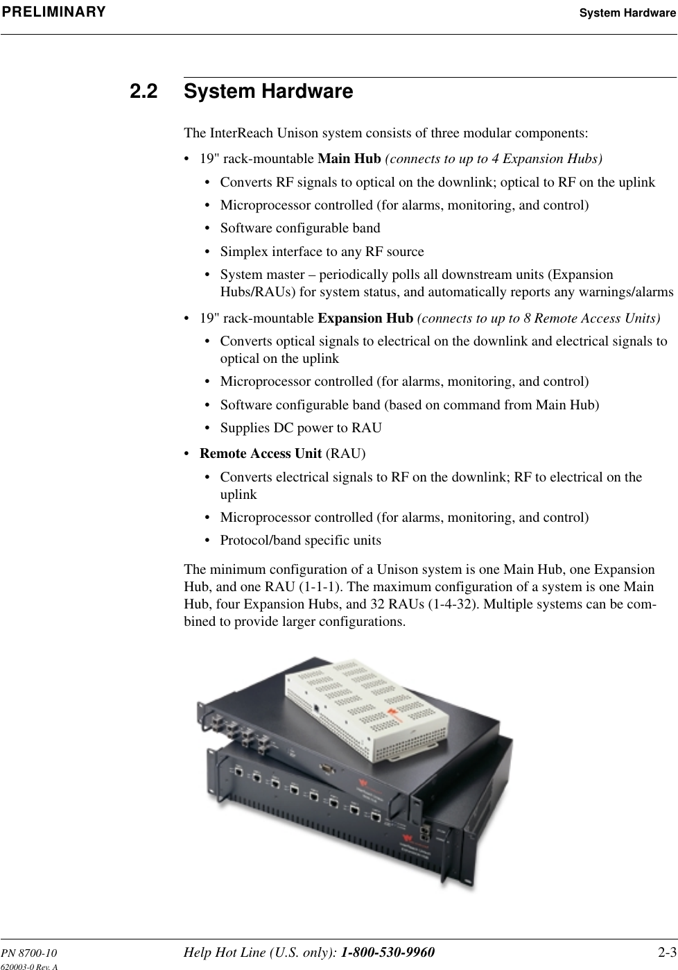
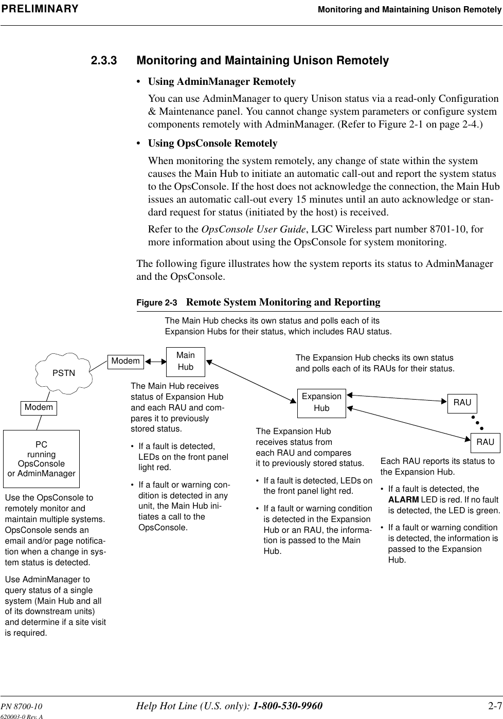
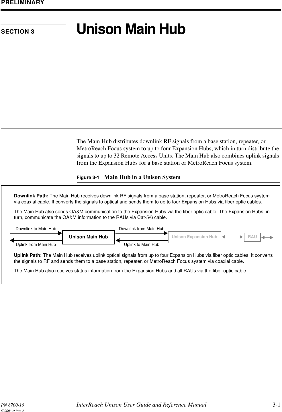
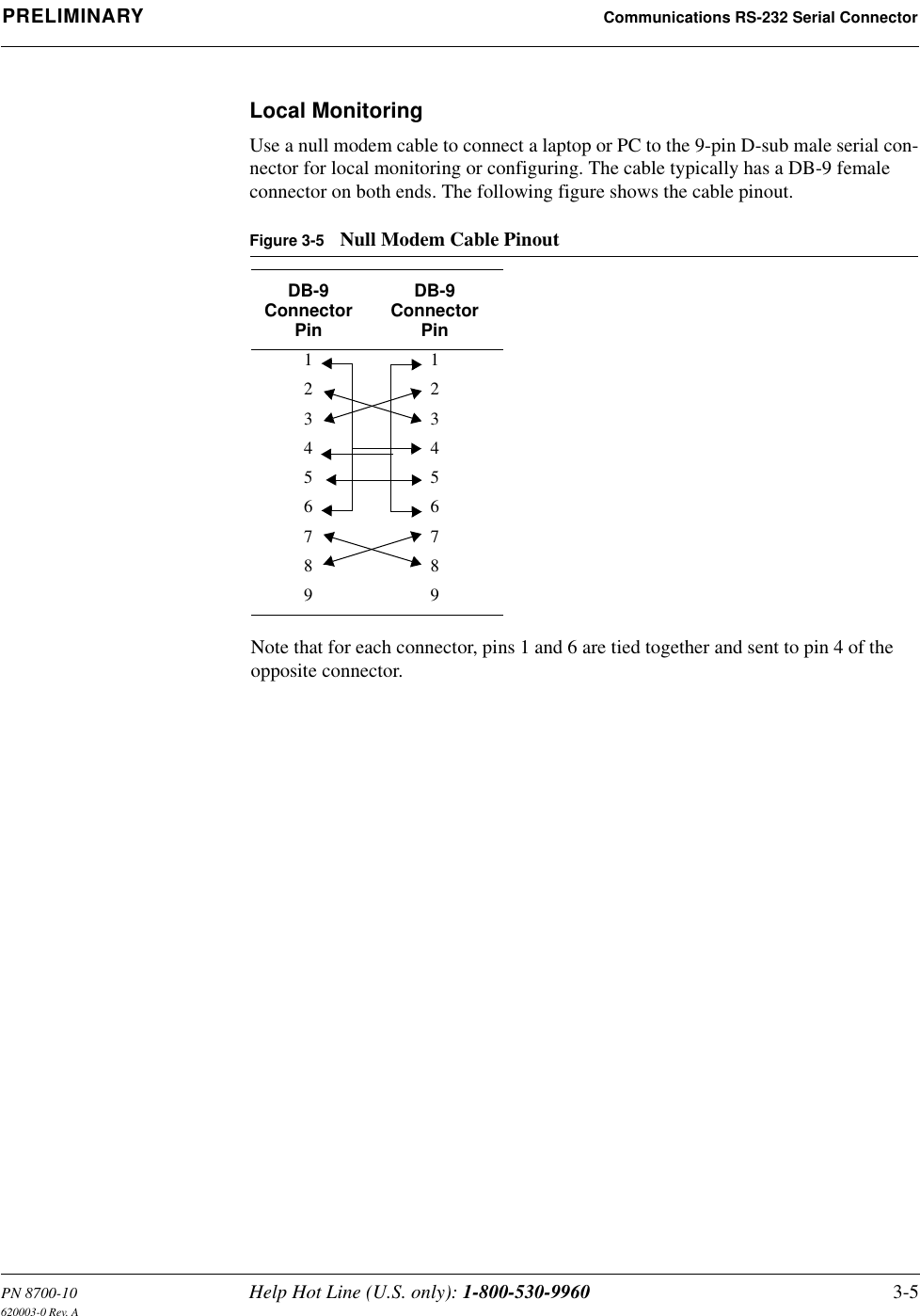
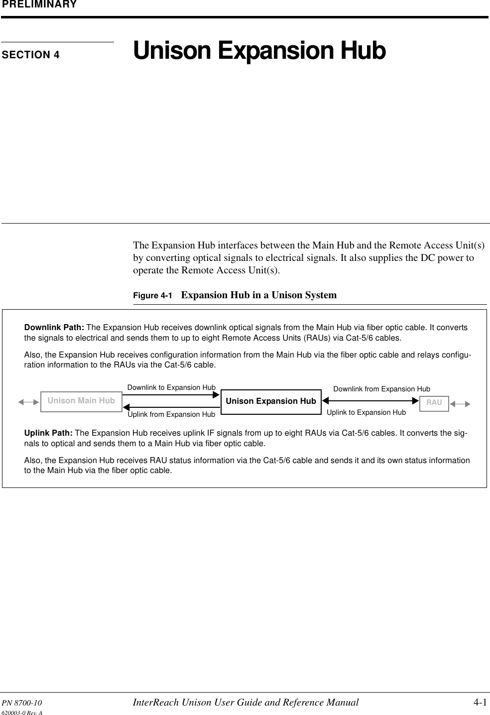
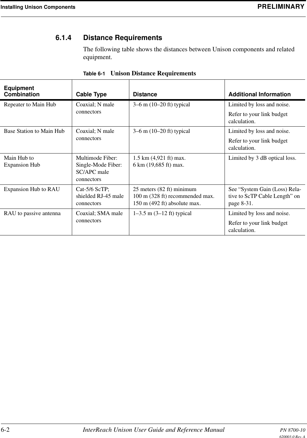
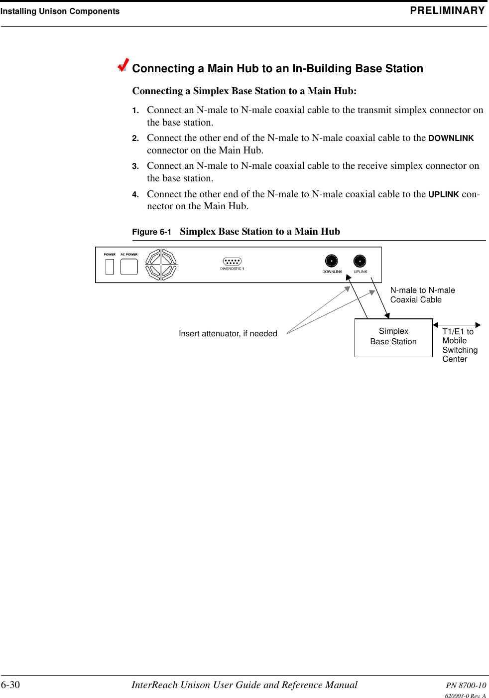
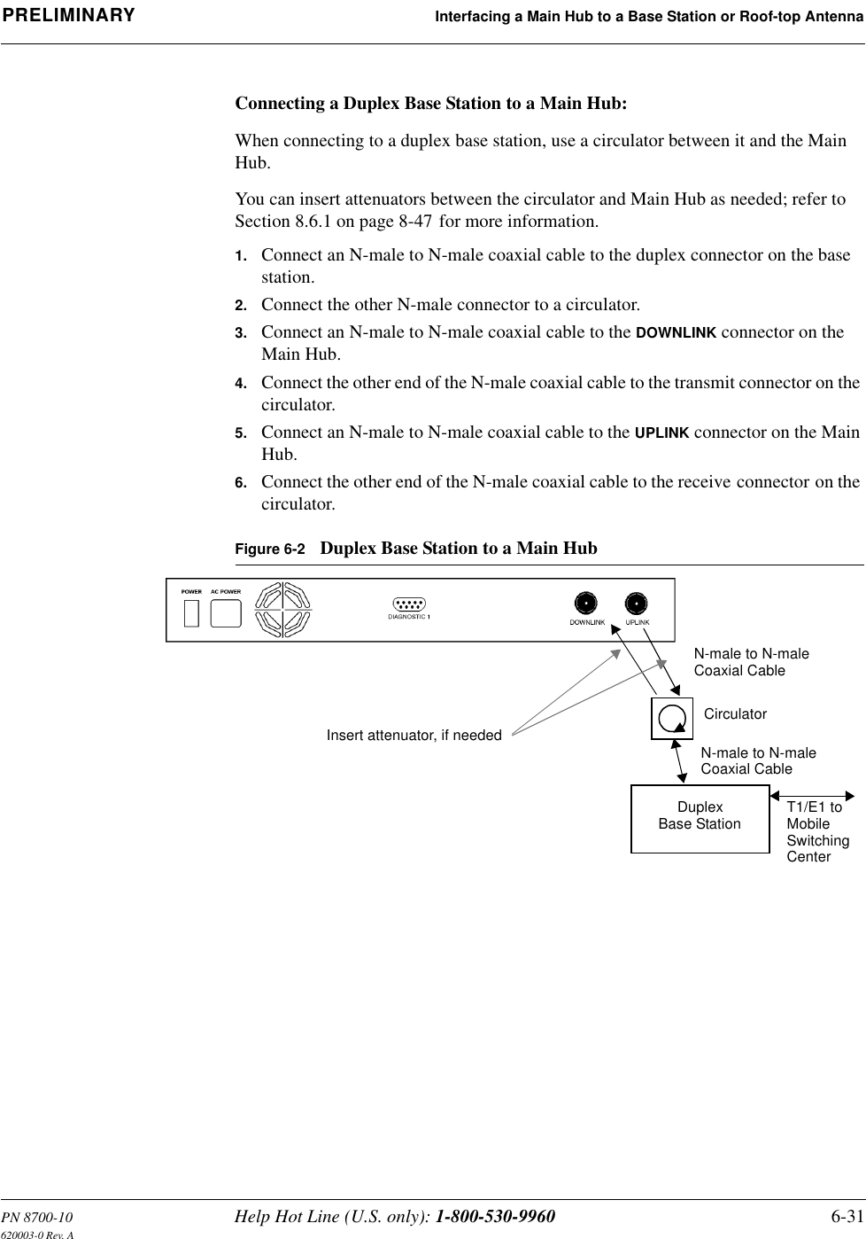
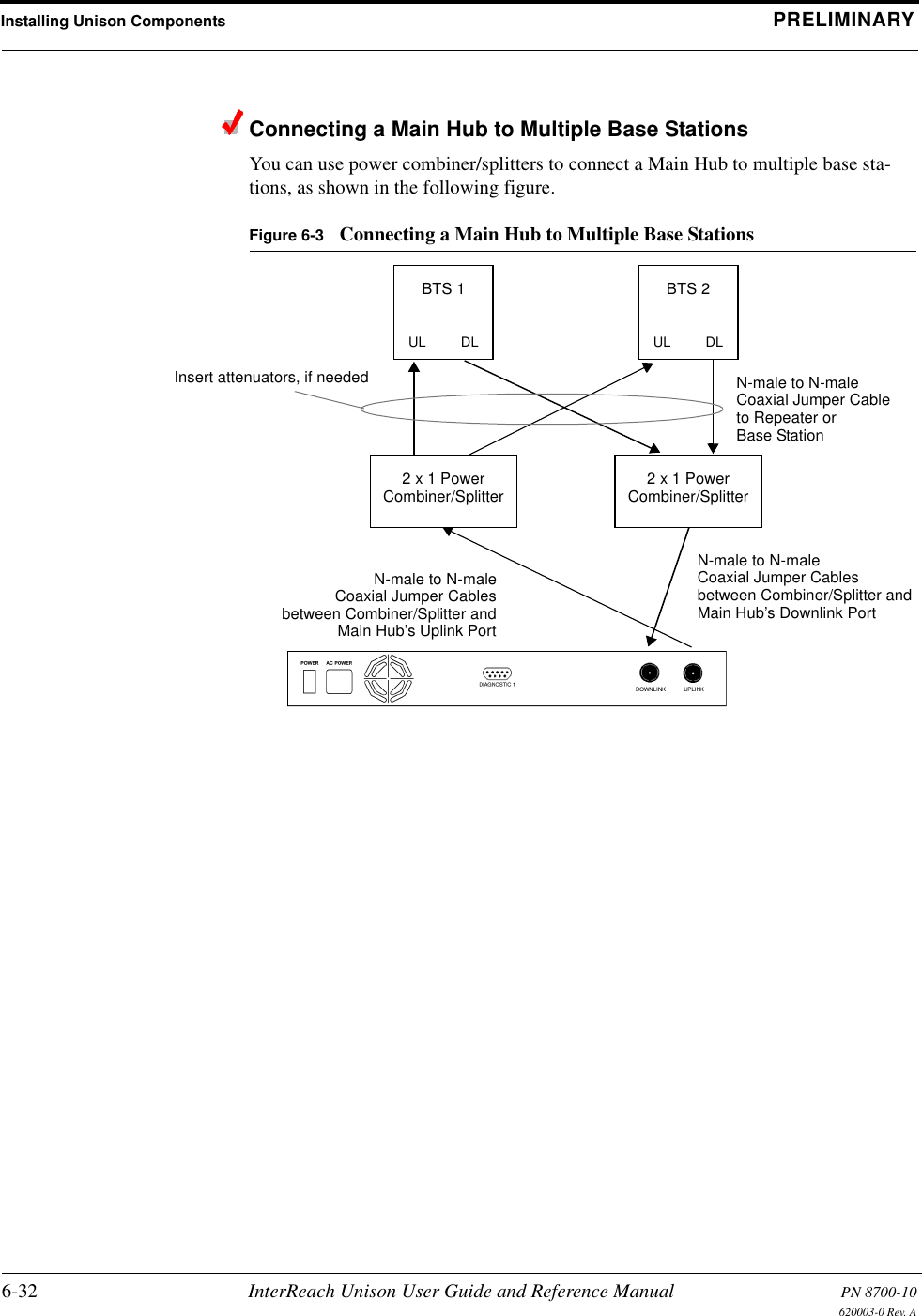
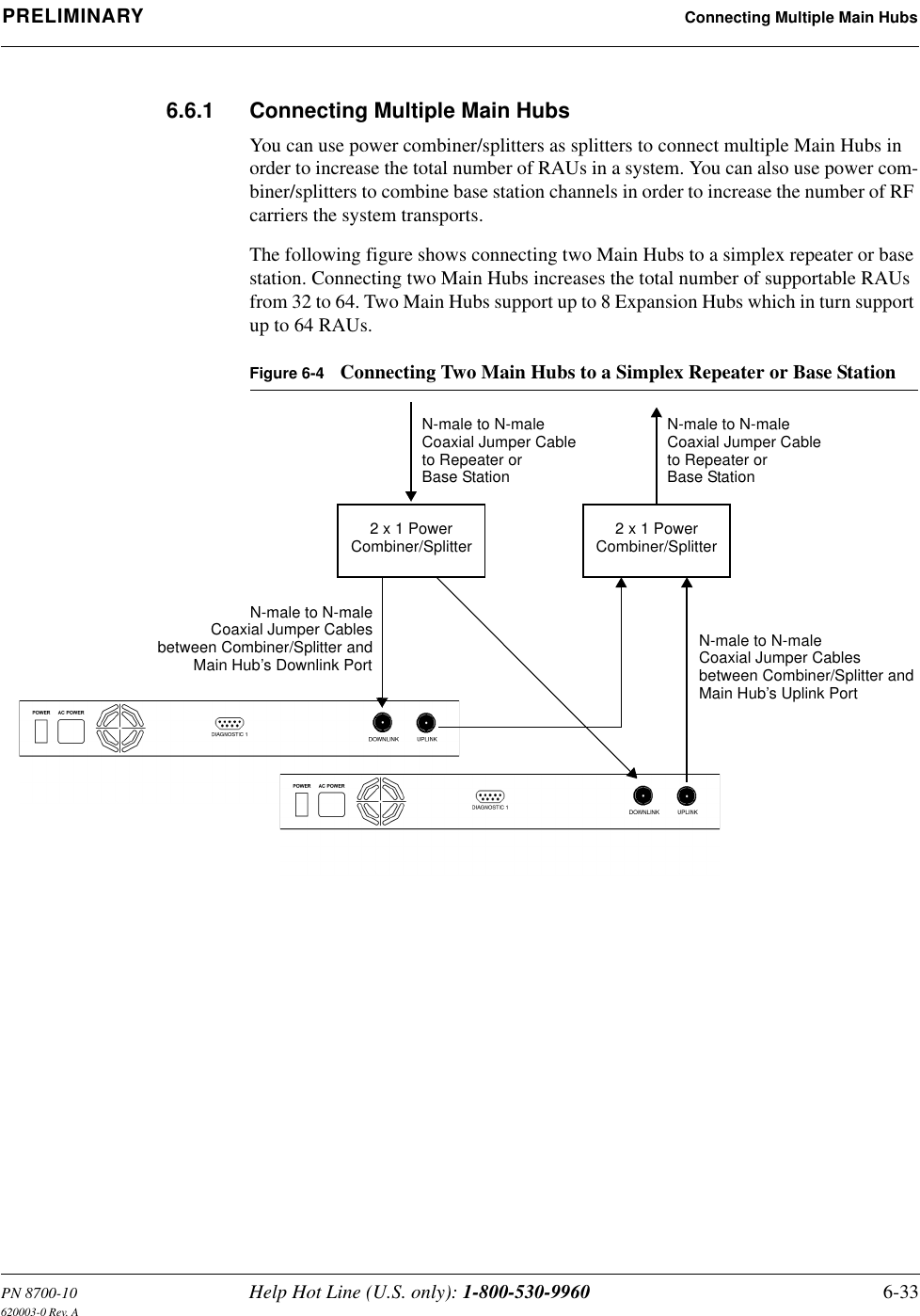
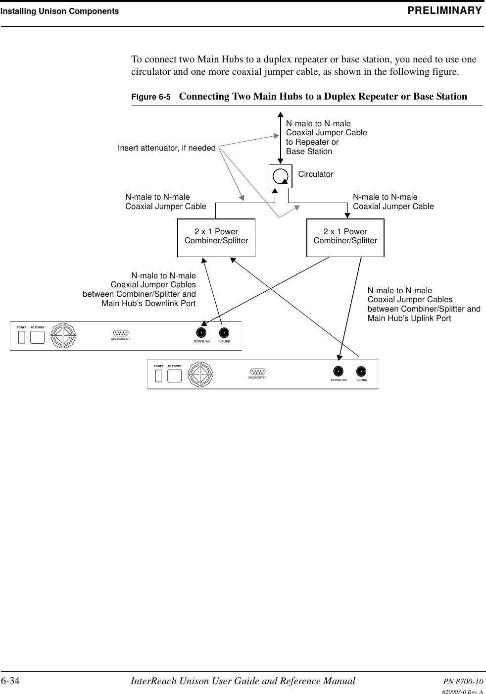
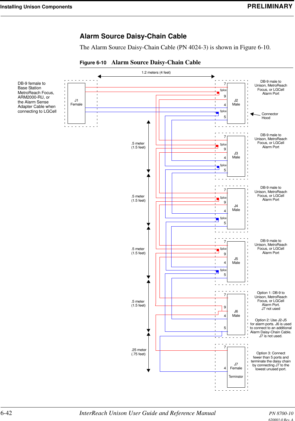
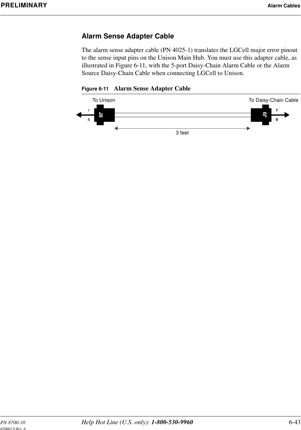
![InterReach™ Unison System Description PRELIMINARY2-2 InterReach Unison User Guide and Reference Manual PN 8700-10620003-0 Rev. AKey System Features•Superior RF performance, particularly in the areas of IP3 and noise figure.•High downlink composite power (+26 dBm), IP3 (+38 dBm) and low uplink noise figure (22 dB for a system with 8 RAUs), enables support of a large number of channels and larger coverage footprint per antenna.• The Main Hub and the Expansion Hub are software configurable. Thus, the fre-quency band can be field configured.• The system supports flexible cabling alternatives, allowing the use of either mul-timode or single-mode fiber (in addition to standard Cat-5 or Cat-6 [Cat-5/6] twisted pair). Cabling type can be selected to meet the resident cabling infrastruc-ture of the facility and unique building topologies.•Extended system “reach”. Using multimode fiber, fiber runs can be as long as 1.5 kilometers. Alternately, with single mode fiber the fiber run can be as long as 6 kilometers (creating a total system “wingspan” of 12 kilometers). And the Cat-5/6 twisted pair cable run can be up to 100 meters recommended maximum (150 meters with RF performance degradation).•Flexible RF configuration capabilities, including:• System gain:– Ability to manually set gain in 1 dB steps on both downlink and uplink.• RAU:– RAU uplink and downlink gain can be attenuated 10 dB.– Uplink level control protects the system from input overload and can be optimized for either a single operator or multi-operators/protocols.– VSWR check on RAU reports if there is a problem with the antenna.• The system firmware effectively “future proofs” the product. When any modi-fications are made to the product, including the addition of new software capabili-ties/services, systems that have already been installed can be upgraded simply by downloading new firmware (either locally or remotely).•Extensive OA&M capabilities, including fault isolation to the field replaceable unit, automatic reporting of all warnings and alarms, and user-friendly graphi-cal-user interface OA&M software packages.](https://usermanual.wiki/ADC-Telecommunications/UNS-IDEN-1.User-Manual-1/User-Guide-173752-Page-22.png)