ADC Telecommunications UNS-IDEN-1 InterReach Unison IDEN User Manual unison
ADC Telecommunications Inc. InterReach Unison IDEN unison
Contents
- 1. User Manual 1
- 2. User Manual 2
- 3. Users Manual
User Manual 1
PN 8700-10
620003-0 Rev. A
Installation, Operation, and Reference Manual
InterReach Unison
TM
®

InterReach Unison User Guide and Reference Manual PN 8700-10
620003-0 Rev. A
This manual is produced for use by LGC Wireless personnel, licensees, and customers. The
information contained herein is the property of LGC Wireless. No part of this document
may be reproduced or transmitted in any form or by any means, electronic or mechanical,
for any purpose, without the express written permission of LGC Wireless.
LGC Wireless reserves the right to make changes, without notice, to the specifications and
materials contained herein, and shall not be responsible for any damages caused by reliance
on the material as presented, including, but not limited to, typographical and listing errors.
Your comments are welcome – they help us improve our products and documentation.
Please address your comments to LGC Wireless, Inc. corporate headquarters in San Jose,
California:
Address 2540 Junction Avenue
San Jose, California
95134-1902 USA
Attn: Marketing Dept.
Phone 1-408-952-2400
Fax 1-408-952-2410
Help Hot Line 1-800-530-9960 (U.S. only)
+1-408-952-2400 (International)
+44(0) 1223 597812 (Europe)
Web Address http://www.lgcwireless.com
e-mail info@lgcwireless.com
service@lgcwireless.com
Copyright © 2001 by LGC Wireless, Inc. Printed in USA. All rights reserved.
Trademarks
All trademarks identified by ™ or ® are trademarks or registered trademark of LGC
Wireless, Inc. All other trademarks belong to their respective owners.

PN 8700-10 InterReach Unison User Guide and Reference Manual
620003-0 Rev. A
Limited Warranty
Seller warrants articles of its manufacture against defective materials or workmanship for a
period of one year from the date of shipment to Purchaser, except as provided in any warranty
applicable to Purchaser on or in the package containing the Goods (which warranty takes
precedence over the following warranty). The liability of Seller under the foregoing warranty
is limited, at Seller’s option, solely to repair or replacement with equivalent Goods, or an
appropriate adjustment not to exceed the sales price to Purchaser, provided that (a) Seller is
notified in writing by Purchaser, within the one year warranty period, promptly upon
discovery of defects, with a detailed description of such defects, (b) Purchaser has obtained a
Return Materials Authorization (RMA) from Seller, which RMA Seller agrees to provide
Purchaser promptly upon request, (c) the defective Goods are returned to Seller,
transportation and other applicable charges prepaid by the Purchaser, and (d) Seller’s
examination of such Goods discloses to its reasonable satisfaction that defects were not
caused by negligence, misuse, improper installation, improper maintenance, accident or
unauthorized repair or alteration or any other cause outside the scope of Purchaser’s warranty
made hereunder. Notwithstanding the foregoing, Seller shall have the option to repair any
defective Goods at Purchaser’s facility. The original warranty period for any Goods that have
been repaired or replaced by seller will not thereby be extended. In addition, all sales will be
subject to standard terms and conditions on the sales contract.

InterReach Unison User Guide and Reference Manual PN 8700-10
620003-0 Rev. A

PN8700-10 InterReach Unison User Guide and Reference Manual i
620003-0 Rev. A
PRELIMINARY
Table of Contents
SECTION 1 General Information . . . . . . . . . . . . . . . . . . . . . . 1-1
1.1 Purpose and Scope . . . . . . . . . . . . . . . . . . . . . . . . . . . . . . . . . 1-2
1.2 Conventions in this Manual . . . . . . . . . . . . . . . . . . . . . . . . . . 1-3
1.3 Acronyms in this Manual . . . . . . . . . . . . . . . . . . . . . . . . . . . . 1-4
1.4 Standards Conformance . . . . . . . . . . . . . . . . . . . . . . . . . . . . . 1-6
1.5 Related Publications . . . . . . . . . . . . . . . . . . . . . . . . . . . . . . . . 1-6
SECTION 2 InterReach™ Unison System Description . . . . 2-1
2.1 System Overview . . . . . . . . . . . . . . . . . . . . . . . . . . . . . . . . . . 2-1
2.2 System Hardware . . . . . . . . . . . . . . . . . . . . . . . . . . . . . . . . . . 2-3
2.3 System OA&M Capabilities . . . . . . . . . . . . . . . . . . . . . . . . . . 2-4
2.3.1 OA&M Software . . . . . . . . . . . . . . . . . . . . . . . . . . . . . . . . . . . 2-5
2.3.2 Configuring, Maintaining, and Monitoring Unison Locally . . 2-5
2.3.3 Monitoring and Maintaining Unison Remotely . . . . . . . . . . . 2-7
2.3.4 Using Alarm Contact Closures . . . . . . . . . . . . . . . . . . . . . . . . 2-8
2.4 System Connectivity . . . . . . . . . . . . . . . . . . . . . . . . . . . . . . . . 2-9
2.5 System Operation . . . . . . . . . . . . . . . . . . . . . . . . . . . . . . . . . 2-10
2.6 System Specifications . . . . . . . . . . . . . . . . . . . . . . . . . . . . . . 2-11
2.6.1 Physical Specifications . . . . . . . . . . . . . . . . . . . . . . . . . . . . . 2-11
2.6.2 Environmental Specifications . . . . . . . . . . . . . . . . . . . . . . . . 2-12
2.6.3 Operating Frequencies . . . . . . . . . . . . . . . . . . . . . . . . . . . . . . 2-12
2.6.4 RF End-to-End Performance . . . . . . . . . . . . . . . . . . . . . . . . . 2-13
SECTION 3 Unison Main Hub . . . . . . . . . . . . . . . . . . . . . . . . 3-1
3.1 Main Hub Front Panel . . . . . . . . . . . . . . . . . . . . . . . . . . . . . . 3-3
3.1.1 Optical Fiber Uplink/Downlink Ports . . . . . . . . . . . . . . . . . . . 3-4
3.1.2 Communications RS-232 Serial Connector . . . . . . . . . . . . . . 3-4
3.1.3 LED Indicators . . . . . . . . . . . . . . . . . . . . . . . . . . . . . . . . . . . . 3-6
3.2 Main Hub Rear Panel . . . . . . . . . . . . . . . . . . . . . . . . . . . . . . . 3-8
3.2.1 Main Hub Rear Panel Connectors . . . . . . . . . . . . . . . . . . . . . . 3-9
3.2.1.1 N-type Female Connectors . . . . . . . . . . . . . . . . . . . . . . 3-9
3.2.1.2 9-pin D-sub Connector . . . . . . . . . . . . . . . . . . . . . . . . . 3-9
3.3 Faults and Warnings . . . . . . . . . . . . . . . . . . . . . . . . . . . . . . . 3-10
3.4 Main Hub Specifications . . . . . . . . . . . . . . . . . . . . . . . . . . . 3-11

PRELIMINARY
ii InterReach Unison User Guide and Reference Manual PN8700-10
620003-0 Rev. A
SECTION 4 Unison Expansion Hub . . . . . . . . . . . . . . . . . . . . 4-1
4.1 Expansion Hub Front Panel . . . . . . . . . . . . . . . . . . . . . . . . . . 4-3
4.1.1 RJ-45 Connectors . . . . . . . . . . . . . . . . . . . . . . . . . . . . . . . . . . . 4-4
4.1.2 Optical Fiber Uplink/Downlink Connectors . . . . . . . . . . . . . . 4-4
4.1.3 LED Indicators . . . . . . . . . . . . . . . . . . . . . . . . . . . . . . . . . . . . . 4-5
4.2 Expansion Hub Rear Panel . . . . . . . . . . . . . . . . . . . . . . . . . . . 4-7
4.3 Faults and Warnings . . . . . . . . . . . . . . . . . . . . . . . . . . . . . . . . 4-8
4.4 Expansion Hub Specifications . . . . . . . . . . . . . . . . . . . . . . . . 4-9
SECTION 5 Unison Remote Access Unit . . . . . . . . . . . . . . . 5-1
5.1 Remote Access Unit Connectors . . . . . . . . . . . . . . . . . . . . . . . 5-3
5.1.1 SMA Connector . . . . . . . . . . . . . . . . . . . . . . . . . . . . . . . . . . . . 5-3
5.1.2 RJ-45 Port . . . . . . . . . . . . . . . . . . . . . . . . . . . . . . . . . . . . . . . . 5-3
5.2 LED Indicators . . . . . . . . . . . . . . . . . . . . . . . . . . . . . . . . . . . . 5-3
5.3 Faults and Warnings . . . . . . . . . . . . . . . . . . . . . . . . . . . . . . . . 5-4
5.4 Remote Access Unit Specifications . . . . . . . . . . . . . . . . . . . . 5-5
SECTION 6 Installing Unison Components . . . . . . . . . . . . . 6-1
6.1 Installation Requirements . . . . . . . . . . . . . . . . . . . . . . . . . . . . 6-1
6.1.1 Component Location Requirements . . . . . . . . . . . . . . . . . . . . 6-1
6.1.2 Cable and Connector Requirements . . . . . . . . . . . . . . . . . . . . 6-1
6.1.3 Neutral Host System Requirements . . . . . . . . . . . . . . . . . . . . . 6-1
6.1.4 Distance Requirements . . . . . . . . . . . . . . . . . . . . . . . . . . . . . . 6-2
6.2 Safety Precautions . . . . . . . . . . . . . . . . . . . . . . . . . . . . . . . . . . 6-3
6.2.1 Installation Guidelines . . . . . . . . . . . . . . . . . . . . . . . . . . . . . . . 6-3
6.2.2 General Safety Precautions . . . . . . . . . . . . . . . . . . . . . . . . . . . 6-3
6.2.3 Fiber Port Safety Precautions . . . . . . . . . . . . . . . . . . . . . . . . . 6-4
6.3 Preparing for System Installation . . . . . . . . . . . . . . . . . . . . . . 6-5
6.3.1 Pre-Installation Inspection . . . . . . . . . . . . . . . . . . . . . . . . . . . . 6-5
6.3.2 Installation Checklist . . . . . . . . . . . . . . . . . . . . . . . . . . . . . . . . 6-6
6.3.3 Tools and Materials Required . . . . . . . . . . . . . . . . . . . . . . . . . 6-8
6.3.4 Optional Accessories . . . . . . . . . . . . . . . . . . . . . . . . . . . . . . . . 6-8
6.4 Unison Component Installation Procedures . . . . . . . . . . . . . . 6-9
6.4.1 Installing RAUs and Passive Antennas . . . . . . . . . . . . . . . . . 6-11
6.4.1.1 Installing RAUs in a Neutral Host System . . . . . . . . . 6-13
6.4.2 Installing Expansion Hubs . . . . . . . . . . . . . . . . . . . . . . . . . . . 6-14
6.4.2.1 Troubleshooting Expansion Hub LEDs During
Installation . . . . . . . . . . . . . . . . . . . . . . . . . . . . . . . . . . 6-21
6.4.2.2 Installing Expansion Hubs in a Neutral Host System . 6-21
6.4.3 Installing a Main Hub . . . . . . . . . . . . . . . . . . . . . . . . . . . . . . 6-22
6.4.4 Installing Main Hubs in a Neutral Host System . . . . . . . . . . 6-23
6.5 Starting and Configuring the System . . . . . . . . . . . . . . . . . . 6-24
6.5.1 Troubleshooting Main Hub LEDs During Installation . . . . . 6-27
6.6 Interfacing a Main Hub to a Base Station or Roof-top
Antenna . . . . . . . . . . . . . . . . . . . . . . . . . . . . . . . . . . . . . . . . . 6-29
6.6.1 Connecting Multiple Main Hubs . . . . . . . . . . . . . . . . . . . . . . 6-33
6.7 Connecting Contact Alarms to a Unison System . . . . . . . . . 6-37
6.7.1 Alarm Source . . . . . . . . . . . . . . . . . . . . . . . . . . . . . . . . . . . . . 6-38

PRELIMINARY
PN8700-10 InterReach Unison User Guide and Reference Manual iii
620003-0 Rev. A
6.7.2 Alarm Sense . . . . . . . . . . . . . . . . . . . . . . . . . . . . . . . . . . . . . 6-40
6.7.3 Alarm Cables . . . . . . . . . . . . . . . . . . . . . . . . . . . . . . . . . . . . . 6-41
SECTION 7 Installing and Using the AdminManager
Software . . . . . . . . . . . . . . . . . . . . . . . . . . . . . . . . 7-1
7.1 Installing the AdminManager Software . . . . . . . . . . . . . . . . . 7-2
7.1.1 PC/Laptop Requirements . . . . . . . . . . . . . . . . . . . . . . . . . . . . 7-2
7.2 Installation Wizard . . . . . . . . . . . . . . . . . . . . . . . . . . . . . . . . 7-13
7.2.1 Step 1: Verify Hardware . . . . . . . . . . . . . . . . . . . . . . . . . . . . 7-14
7.2.1.1 Description of Step 1 Panel . . . . . . . . . . . . . . . . . . . . . 7-15
7.2.2 Step 2: Set Operation Band . . . . . . . . . . . . . . . . . . . . . . . . . . 7-16
7.2.2.1 Description of Step 2 Panel . . . . . . . . . . . . . . . . . . . . . 7-18
7.2.3 Step 3: Configure System Parameters . . . . . . . . . . . . . . . . . . 7-20
7.2.3.1 Description of Step 3 Panel . . . . . . . . . . . . . . . . . . . . . 7-21
7.2.4 Step 4: Final System Test . . . . . . . . . . . . . . . . . . . . . . . . . . . 7-22
7.2.4.1 Description of Step 4 Panel . . . . . . . . . . . . . . . . . . . . . 7-23
7.2.5 Finish Panel . . . . . . . . . . . . . . . . . . . . . . . . . . . . . . . . . . . . . . 7-24
7.2.5.1 Description of Finish Panel . . . . . . . . . . . . . . . . . . . . . 7-24
7.3 Configuration & Maintenance Panel . . . . . . . . . . . . . . . . . . 7-25
7.3.1 Window Description . . . . . . . . . . . . . . . . . . . . . . . . . . . . . . . 7-26
7.3.2 Options when Connected Locally . . . . . . . . . . . . . . . . . . . . . 7-29
7.3.3 Read-Only Options when Connected Remotely . . . . . . . . . . 7-34
7.4 Upgrading Firmware . . . . . . . . . . . . . . . . . . . . . . . . . . . . . . . 7-38
7.5 System Status Tree . . . . . . . . . . . . . . . . . . . . . . . . . . . . . . . . 7-39
7.5.1 System Status Tree Icons . . . . . . . . . . . . . . . . . . . . . . . . . . . . 7-39
SECTION 8 Designing a Unison Solution . . . . . . . . . . . . . . . 8-1
8.1 Maximum Output Power per Carrier at RAU . . . . . . . . . . . . . 8-3
8.2 Estimating RF Coverage . . . . . . . . . . . . . . . . . . . . . . . . . . . . 8-19
8.2.1 Path Loss Equation . . . . . . . . . . . . . . . . . . . . . . . . . . . . . . . . 8-20
8.2.2 Coverage Distance . . . . . . . . . . . . . . . . . . . . . . . . . . . . . . . . . 8-21
8.2.3 Examples of Design Estimates . . . . . . . . . . . . . . . . . . . . . . . 8-27
8.3 System Gain . . . . . . . . . . . . . . . . . . . . . . . . . . . . . . . . . . . . . 8-31
8.3.1 System Gain (Loss) Relative to ScTP Cable Length . . . . . . 8-31
8.4 Link Budget Analysis . . . . . . . . . . . . . . . . . . . . . . . . . . . . . . 8-32
8.4.1 Elements of a Link Budget for Narrowband Standards . . . . 8-33
8.4.2 Narrowband Link Budget Analysis for a Microcell
Application . . . . . . . . . . . . . . . . . . . . . . . . . . . . . . . . . . . . . . 8-35
8.4.3 Elements of a Link Budget for CDMA Standards . . . . . . . . 8-37
8.4.4 Spread Spectrum Link Budget Analysis for a Microcell
Application . . . . . . . . . . . . . . . . . . . . . . . . . . . . . . . . . . . . . . 8-40
8.4.5 Considerations for Re-Radiation (over-the-air) Systems . . . 8-44
8.5 Optical Power Budget . . . . . . . . . . . . . . . . . . . . . . . . . . . . . . 8-45
8.6 Connecting a Main Hub to a Base Station . . . . . . . . . . . . . . 8-46
8.6.1 Attenuation . . . . . . . . . . . . . . . . . . . . . . . . . . . . . . . . . . . . . . 8-47
8.6.2 Uplink Attenuation . . . . . . . . . . . . . . . . . . . . . . . . . . . . . . . . 8-48
8.6.2.1 Uplink Attenuation Exception: CDMA . . . . . . . . . . . . 8-49
8.7 Designing for a Neutral Host System . . . . . . . . . . . . . . . . . . 8-50

PRELIMINARY
iv InterReach Unison User Guide and Reference Manual PN8700-10
620003-0 Rev. A
8.7.1 Capacity of the Unison Neutral Host System . . . . . . . . . . . . 8-50
8.7.2 Example Unison Neutral Host System . . . . . . . . . . . . . . . . . 8-51
SECTION 9 Replacing Unison Components in an
Operating System . . . . . . . . . . . . . . . . . . . . . . . . 9-1
9.1 Replacing an RAU . . . . . . . . . . . . . . . . . . . . . . . . . . . . . . . . . 9-1
9.2 Replacing an Expansion Hub . . . . . . . . . . . . . . . . . . . . . . . . . 9-3
9.3 Replacing a Main Hub . . . . . . . . . . . . . . . . . . . . . . . . . . . . . . 9-4
SECTION 10 Maintenance, Troubleshooting, and
Technical Assistance . . . . . . . . . . . . . . . . . . . . 10-1
10.1 Maintenance . . . . . . . . . . . . . . . . . . . . . . . . . . . . . . . . . . . . . 10-1
10.2 Troubleshooting . . . . . . . . . . . . . . . . . . . . . . . . . . . . . . . . . . 10-2
10.2.1 Fault Indications . . . . . . . . . . . . . . . . . . . . . . . . . . . . . . . . . . 10-3
10.2.2 Warning Indications . . . . . . . . . . . . . . . . . . . . . . . . . . . . . . . 10-11
10.3 LED Troubleshooting Guide . . . . . . . . . . . . . . . . . . . . . . . 10-13
10.3.1 Troubleshooting Main Hub LEDs During Normal
Operation . . . . . . . . . . . . . . . . . . . . . . . . . . . . . . . . . . . . . . . 10-14
10.3.2 Troubleshooting Expansion Hub LEDs During Normal
Operation . . . . . . . . . . . . . . . . . . . . . . . . . . . . . . . . . . . . . . . 10-15
10.4 Technical Assistance . . . . . . . . . . . . . . . . . . . . . . . . . . . . . 10-17
APPENDIX A Cables and Connectors . . . . . . . . . . . . . . . . . . . A-1
A.1 Cat-5/6 Cable (ScTP) . . . . . . . . . . . . . . . . . . . . . . . . . . . . . . .A-1
A.2 Fiber Optical Cables . . . . . . . . . . . . . . . . . . . . . . . . . . . . . . . .A-3
A.3 Coaxial Cable . . . . . . . . . . . . . . . . . . . . . . . . . . . . . . . . . . . . .A-3
APPENDIX B InterReach Unison Property Sheet . . . . . . . . . . B-1
APPENDIX C Compliance . . . . . . . . . . . . . . . . . . . . . . . . . . . . . C-1
C.1 Safety Requirements . . . . . . . . . . . . . . . . . . . . . . . . . . . . . . . . C-1
C.2 Radio/EMC Requirements . . . . . . . . . . . . . . . . . . . . . . . . . . .C-2
APPENDIX D Glossary . . . . . . . . . . . . . . . . . . . . . . . . . . . . . . . . D-1

PN8700-10 InterReach Unison User Guide and Reference Manual v
620003-0 Rev. A
PRELIMINARY
List of Figures
Figure 2-1 OA&M Communications . . . . . . . . . . . . . . . . . . . . . . . . . . . . . . . . . . . . 2-4
Figure 2-2 Local System Monitoring and Reporting . . . . . . . . . . . . . . . . . . . . . . . 2-6
Figure 2-3 Remote System Monitoring and Reporting . . . . . . . . . . . . . . . . . . . . . . 2-7
Figure 2-4 Unison’s Double Star Architecture . . . . . . . . . . . . . . . . . . . . . . . . . . . . 2-9
Figure 3-1 Main Hub in a Unison System . . . . . . . . . . . . . . . . . . . . . . . . . . . . . . . . 3-1
Figure 3-2 Main Hub Block Diagram . . . . . . . . . . . . . . . . . . . . . . . . . . . . . . . . . . . 3-2
Figure 3-3 Main Hub Front Panel . . . . . . . . . . . . . . . . . . . . . . . . . . . . . . . . . . . . . . 3-3
Figure 3-4 Standard Serial Cable Pinout . . . . . . . . . . . . . . . . . . . . . . . . . . . . . . . . . 3-4
Figure 3-5 Null Modem Cable Pinout . . . . . . . . . . . . . . . . . . . . . . . . . . . . . . . . . . . 3-5
Figure 3-6 Main Hub Rear Panel . . . . . . . . . . . . . . . . . . . . . . . . . . . . . . . . . . . . . . . 3-8
Figure 4-1 Expansion Hub in a Unison System . . . . . . . . . . . . . . . . . . . . . . . . . . . . 4-1
Figure 4-2 Expansion Hub Block Diagram . . . . . . . . . . . . . . . . . . . . . . . . . . . . . . . 4-2
Figure 4-3 Expansion Hub Front Panel . . . . . . . . . . . . . . . . . . . . . . . . . . . . . . . . . . 4-3
Figure 4-4 Expansion Hub Rear Panel . . . . . . . . . . . . . . . . . . . . . . . . . . . . . . . . . . . 4-7
Figure 5-1 Remote Access Unit in a Unison System . . . . . . . . . . . . . . . . . . . . . . . . 5-1
Figure 5-2 Remote Access Unit Block Diagram . . . . . . . . . . . . . . . . . . . . . . . . . . . 5-2
Figure 6-1 Simplex Base Station to a Main Hub . . . . . . . . . . . . . . . . . . . . . . . . . . 6-30
Figure 6-2 Duplex Base Station to a Main Hub . . . . . . . . . . . . . . . . . . . . . . . . . . . 6-31
Figure 6-3 Connecting a Main Hub to Multiple Base Stations . . . . . . . . . . . . . . . 6-32
Figure 6-4 Connecting Two Main Hubs to a Simplex Repeater or Base Station . 6-33
Figure 6-5 Connecting Two Main Hubs to a Duplex Repeater or Base Station . . 6-34
Figure 6-6 Connecting MetroReach to Unison . . . . . . . . . . . . . . . . . . . . . . . . . . . 6-38
Figure 6-7 Connecting a BTS to Unison . . . . . . . . . . . . . . . . . . . . . . . . . . . . . . . . 6-39
Figure 6-8 Connecting LGCell to Unison . . . . . . . . . . . . . . . . . . . . . . . . . . . . . . . 6-40
Figure 6-9 5-port Daisy-Chained Alarm Cable . . . . . . . . . . . . . . . . . . . . . . . . . . . 6-41
Figure 6-10 Alarm Source Daisy-Chain Cable . . . . . . . . . . . . . . . . . . . . . . . . . . . . 6-42
Figure 6-11 Alarm Sense Adapter Cable . . . . . . . . . . . . . . . . . . . . . . . . . . . . . . . . . 6-43
Figure 7-1 PC Connected to Main Hub . . . . . . . . . . . . . . . . . . . . . . . . . . . . . . . . . . 7-1

PRELIMINARY
vi InterReach Unison User Guide and Reference Manual PN8700-10
620003-0 Rev. A
Figure 7-2 AdminManager Start Window . . . . . . . . . . . . . . . . . . . . . . . . . . . . . . . 7-11
Figure 7-3 Step 1: Verify Hardware Panel . . . . . . . . . . . . . . . . . . . . . . . . . . . . . . . 7-14
Figure 7-4 Step 2: Set Operation Band . . . . . . . . . . . . . . . . . . . . . . . . . . . . . . . . . 7-16
Figure 7-5 Step 3: Configure System Parameters . . . . . . . . . . . . . . . . . . . . . . . . . 7-20
Figure 7-6 Step 4: Final System Test . . . . . . . . . . . . . . . . . . . . . . . . . . . . . . . . . . . 7-22
Figure 7-7 Finish Panel . . . . . . . . . . . . . . . . . . . . . . . . . . . . . . . . . . . . . . . . . . . . . 7-24
Figure 7-8 Configuration & Maintenance Window . . . . . . . . . . . . . . . . . . . . . . . . 7-25
Figure 7-9 Firmware Update Window . . . . . . . . . . . . . . . . . . . . . . . . . . . . . . . . . . 7-38
Figure 8-1 Determining Path Loss between the Antenna and the Wireless Device 8-19
Figure 8-2 Connecting Main Hubs to a Simplex Base Station . . . . . . . . . . . . . . . 8-46
Figure 8-3 Main Hub to Duplex Base Station or Repeater Connections . . . . . . . . 8-47
Figure A-1 Wiring Map for Cat-5/6 Cable . . . . . . . . . . . . . . . . . . . . . . . . . . . . . . . .A-2

PN8700-10 InterReach Unison User Guide and Reference Manual vii
620003-0 Rev. A
PRELIMINARY
List of Tables
Table 2-1 Cellular RF End-to-End Performance using 2 km of
Single-Mode Fiber . . . . . . . . . . . . . . . . . . . . . . . . . . . . . . . . . . . . . . . . 2-13
Table 2-2 iDEN RF End-to-End Performance using 2 km of Single-Mode Fiber 2-13
Table 2-3 GSM RF End-to-End Performance using 2 km of Single-Mode Fiber 2-14
Table 2-4 EGSM RF End-to-End Performance using 2 km of Single-Mode
Fiber . . . . . . . . . . . . . . . . . . . . . . . . . . . . . . . . . . . . . . . . . . . . . . . . . . 2-15
Table 2-5 EGSM RF End-to-End Performance using 1 km of Multimode Fiber 2-15
Table 2-6 DCS RF End-to-End Performance using 2 km of Single-Mode Fiber 2-16
Table 2-7 DCS RF End-to-End Performance using 1 km of Multimode Fiber . . 2-16
Table 2-8 PCS RF End-to-End Performance using 2 km of Single-Mode Fiber 2-17
Table 2-9 WCDMA RF End-to-End Performance using 2 km of Single-Mode
Fiber . . . . . . . . . . . . . . . . . . . . . . . . . . . . . . . . . . . . . . . . . . . . . . . . . . 2-18
Table 3-1 Main Hub Status LED States . . . . . . . . . . . . . . . . . . . . . . . . . . . . . . . . . 3-6
Table 3-2 Main Hub Port LED States . . . . . . . . . . . . . . . . . . . . . . . . . . . . . . . . . . 3-7
Table 3-3 Main Hub Specifications . . . . . . . . . . . . . . . . . . . . . . . . . . . . . . . . . . . 3-11
Table 4-1 Expansion Hub Unit Status and DL/UL Status LED States . . . . . . . . . 4-5
Table 4-2 Expansion Hub Port LED States . . . . . . . . . . . . . . . . . . . . . . . . . . . . . . 4-6
Table 4-3 Expansion Hub Specifications . . . . . . . . . . . . . . . . . . . . . . . . . . . . . . . 4-9
Table 5-1 Remote Access Unit LED States . . . . . . . . . . . . . . . . . . . . . . . . . . . . . . 5-3
Table 5-2 Remote Access Unit Specifications . . . . . . . . . . . . . . . . . . . . . . . . . . . 5-5
Table 6-1 Unison Distance Requirements . . . . . . . . . . . . . . . . . . . . . . . . . . . . . . . 6-2
Table 6-2 Installation Checklist . . . . . . . . . . . . . . . . . . . . . . . . . . . . . . . . . . . . . . . 6-6
Table 6-3 Tools and Materials Required for Component Installation . . . . . . . . . . 6-8
Table 6-4 Optional Accessories for Component Installation . . . . . . . . . . . . . . . . 6-8
Table 6-5 Troubleshooting Expansion Hub LEDs During Installation . . . . . . . . 6-21
Table 6-6 Troubleshooting Main Hub LEDs During Installation Power On . . . 6-27
Table 7-1 Configuration and Maintenance Window Options . . . . . . . . . . . . . . . 7-26
Table 7-2 Frequency Bands Adjacent to System Configured Bands . . . . . . . . . 7-31

PRELIMINARY
viii InterReach Unison User Guide and Reference Manual PN8700-10
620003-0 Rev. A
Table 7-3 System Status Tree Icons . . . . . . . . . . . . . . . . . . . . . . . . . . . . . . . . . . . 7-39
Table 8-1 800 MHz (AMPS) Power per Carrier . . . . . . . . . . . . . . . . . . . . . . . . . . 8-4
Table 8-2 800 MHz (TDMA) Power per Carrier . . . . . . . . . . . . . . . . . . . . . . . . . . 8-5
Table 8-3 800 MHz (CDMA) Power per Carrier . . . . . . . . . . . . . . . . . . . . . . . . . . 8-6
Table 8-4 800 MHz (iDEN) Power per Carrier . . . . . . . . . . . . . . . . . . . . . . . . . . . 8-7
Table 8-5 900 MHz (GSM or EGSM) Power per Carrier . . . . . . . . . . . . . . . . . . .8-8
Table 8-6 900 MHz (EDGE) Power per Carrier . . . . . . . . . . . . . . . . . . . . . . . . . . 8-9
Table 8-7 1800 MHz (DCS) Power per Carrier . . . . . . . . . . . . . . . . . . . . . . . . . . 8-10
Table 8-8 1800 MHz (EDGE) Power per Carrier . . . . . . . . . . . . . . . . . . . . . . . . 8-11
Table 8-9 1800 MHz (CDMA Korea) Power per Carrier . . . . . . . . . . . . . . . . . . 8-12
Table 8-10 1900 MHz (TDMA) Power per Carrier . . . . . . . . . . . . . . . . . . . . . . . . 8-13
Table 8-11 1900 MHz (GSM) Power per Carrier . . . . . . . . . . . . . . . . . . . . . . . . . 8-14
Table 8-12 1900 MHz (CDMA) Power per Carrier . . . . . . . . . . . . . . . . . . . . . . . . 8-15
Table 8-13 1900 MHz (EDGE) Power per Carrier . . . . . . . . . . . . . . . . . . . . . . . . 8-16
Table 8-14 2.1 GHz (WCDMA) Power per Carrier . . . . . . . . . . . . . . . . . . . . . . . . 8-17
Table 8-15 Coaxial Cable Losses . . . . . . . . . . . . . . . . . . . . . . . . . . . . . . . . . . . . . . 8-19
Table 8-16 Average Signal Loss of Common Building Materials . . . . . . . . . . . . . 8-20
Table 8-17 Estimated Path Loss Slope for Different In-Building Environments . 8-21
Table 8-18 Frequency Bands and the Value of the first Term in Equation (3) . . . 8-22
Table 8-19 Approximate Radiated Distance from Antenna
for 800 MHz Cellular Applications . . . . . . . . . . . . . . . . . . . . . . . . . . . 8-23
Table 8-20 Approximate Radiated Distance from Antenna
for 800 MHz iDEN Applications . . . . . . . . . . . . . . . . . . . . . . . . . . . . . 8-23
Table 8-21 Approximate Radiated Distance from Antenna
for 900 MHz GSM Applications . . . . . . . . . . . . . . . . . . . . . . . . . . . . . 8-24
Table 8-22 Approximate Radiated Distance from Antenna
for 900 MHz EGSM Applications . . . . . . . . . . . . . . . . . . . . . . . . . . . . 8-24
Table 8-23 Approximate Radiated Distance from Antenna
for 1800 MHz DCS Applications . . . . . . . . . . . . . . . . . . . . . . . . . . . . 8-25
Table 8-24 Approximate Radiated Distance from Antenna
for 1800 MHz CDMA (Korea) Applications . . . . . . . . . . . . . . . . . . . 8-25
Table 8-25 Approximate Radiated Distance from Antenna
for 1900 MHz PCS Applications . . . . . . . . . . . . . . . . . . . . . . . . . . . . . 8-26
Table 8-26 Approximate Radiated Distance from Antenna
for 2.1 GHz UMTS Applications . . . . . . . . . . . . . . . . . . . . . . . . . . . . 8-26
Table 8-27 System Gain (Loss) Relative to ScTP Cable Length . . . . . . . . . . . . . . 8-31
Table 8-28 Link Budget Considerations for Narrowband Systems . . . . . . . . . . . . 8-33
Table 8-29 Distribution of Power within a CDMA Signal . . . . . . . . . . . . . . . . . . 8-37
Table 8-30 Additional Link Budget Considerations for CDMA . . . . . . . . . . . . . . 8-38
Table 10-1 Main Hub Faults . . . . . . . . . . . . . . . . . . . . . . . . . . . . . . . . . . . . . . . . . 10-3

PRELIMINARY
PN8700-10 InterReach Unison User Guide and Reference Manual ix
620003-0 Rev. A
Table 10-2 Expansion Hub Faults . . . . . . . . . . . . . . . . . . . . . . . . . . . . . . . . . . . . . 10-6
Table 10-3 Remote Access Unit Faults . . . . . . . . . . . . . . . . . . . . . . . . . . . . . . . . . 10-9
Table 10-4 Main Hub Warnings . . . . . . . . . . . . . . . . . . . . . . . . . . . . . . . . . . . . . 10-11
Table 10-5 Expansion Hub Warnings . . . . . . . . . . . . . . . . . . . . . . . . . . . . . . . . . 10-12
Table 10-6 Remote Access Unit Warnings . . . . . . . . . . . . . . . . . . . . . . . . . . . . . 10-12
Table 10-7 Troubleshooting Main Hub Port LEDs During Normal Operation . . 10-14
Table 10-8 Troubleshooting Main Hub Status LEDs During Normal Operation 10-14
Table 10-9 Troubleshooting Expansion Hub Port LEDs During Normal
Operation . . . . . . . . . . . . . . . . . . . . . . . . . . . . . . . . . . . . . . . . . . . . . . 10-15
Table 10-10 Troubleshooting Expansion Hub Status LEDs During Normal
Operation . . . . . . . . . . . . . . . . . . . . . . . . . . . . . . . . . . . . . . . . . . . . . 10-16
Table A-1 Cat-5/6 Twisted Pair Assignment . . . . . . . . . . . . . . . . . . . . . . . . . . . . . A-1

PRELIMINARY
xInterReach Unison User Guide and Reference Manual PN8700-10
620003-0 Rev. A

PN 8700-10 InterReach Unison User Guide and Reference Manual 1-1
620003-0 Rev. A
PRELIMINARY
SECTION 1 General Information
This section contains the following subsections:
• Section 1.1 Purpose and Scope . . . . . . . . . . . . . . . . . . . . . . . . . . . . . . . . . . . . 1-2
• Section 1.2 Conventions in this Manual . . . . . . . . . . . . . . . . . . . . . . . . . . . . . 1-3
• Section 1.3 Acronyms in this Manual . . . . . . . . . . . . . . . . . . . . . . . . . . . . . . . 1-4
• Section 1.4 Standards Conformance . . . . . . . . . . . . . . . . . . . . . . . . . . . . . . . . 1-6
• Section 1.5 Related Publications . . . . . . . . . . . . . . . . . . . . . . . . . . . . . . . . . . . 1-6

General Information PRELIMINARY
1-2 InterReach Unison User Guide and Reference Manual PN 8700-10
620003-0 Rev. A
1.1 Purpose and Scope
This document describes the InterReachTM Unison system components and the
AdminManager software. Included is information for the installation, operation, and
maintenance of the system. Also included is information about how to use the
AdminManager software to install and configure the Unison system, as well as to per-
form other tasks such as change gain settings and check system status.
PN 8700-10 Help Hot Line (U.S. only): 1-800-530-9960 1-3
620003-0 Rev. A
PRELIMINARY Conventions in this Manual
1.2 Conventions in this Manual
The following table lists the type style conventions used in this manual.
Measurements are listed first in metric units, followed by U.S. Customary System of
units in parentheses. For example:
0° to 45°C (32° to 113°F)
The following symbols are used to highlight certain information as described.
NOTE: This format is used to emphasize text with special significance or
importance, and to provide supplemental information.
CAUTION: This format is used when a given action or omitted
action can cause or contribute to a hazardous condition. Damage to
the equipment can occur.
WARNING: This format is used when a given action or omitted action
can result in catastrophic damage to the equipment or cause injury to
the user.
Procedure
This format is used to highlight a procedure.
Convention Description
bold Used for emphasis
BOLD CAPS Used to indicate labels on equipment
SMALL CAPS Used to highlight software window buttons

General Information PRELIMINARY
1-4 InterReach Unison User Guide and Reference Manual PN 8700-10
620003-0 Rev. A
1.3 Acronyms in this Manual
Acronym Definition
AGC automatic gain control
ALC automatic level control
AMPS Advanced Mobile Phone Service
BTS base transceiver station
Cat-5/6 Category 5 or Category 6 (twisted pair cable)
CDMA code division multiple access
CDPD cellular digital packet data
dB decibel
dBm decibels relative to 1 milliwatt
DC direct current
DCS Digital Communications System
DL downlink
EDGE Enhanced Data Rates for Global Evolution
EGSM Extended Global Standard for Mobile Communications
EH Expansion Hub
GHz gigahertz
GPRS General Packet Radio Service
GSM Groupe Speciale Mobile (now translated in English as Global Standard
for Mobile Communications)
Hz hertz
IF intermediate frequency
iDEN Integrated Digital Enhanced Network (Motorola variant of TDMA
wireless)
LAN local area network
LO local oscillator
mA milliamps
MBS microcellular base station
MH Main Hub
MHz megahertz
MMF multi-mode fiber
MTBF mean time between failures
NF noise figure
nm nanometer
OA&M operation, administration, and maintenance

PN 8700-10 Help Hot Line (U.S. only): 1-800-530-9960 1-5
620003-0 Rev. A
PRELIMINARY Acronyms in this Manual
PCS Personal Communication Services
PLL phase-locked loop
PLS path loss slope
RAU Remote Access Unit
RF radio frequency
RSSI received signal strength indicator
SC/APC fiber optic connector complying with NTT SC standard, angle-polished
SMA sub-miniature A connector (coaxial cable connector type)
SMF single-mode fiber
ST straight tip (fiber optic cable connector type)
ScTP screened twisted pair
TDMA time division multiple access
UL uplink; Underwriters Laboratories
uW microwatts
UMTS Universal Mobile Telecommunications System
UPS uninterruptable power supply
Wwatt
WCDMA wideband code division multiple access
Acronym Definition

General Information PRELIMINARY
1-6 InterReach Unison User Guide and Reference Manual PN 8700-10
620003-0 Rev. A
1.4 Standards Conformance
• Utilizes the TIA/EIA 568-A Ethernet cabling standards for ease of installation.
• See Appendix C for compliance information.
1.5 Related Publications
•MetroReach Focus Configuration, Installation, and Reference Manual; LGC
Wireless part number 8500-10
•LGCell Version 4.0 Installation, Operation, and Reference Manual; LGC Wireless
part number 8100-50
•OpsConsole User Guide; LGC Wireless part number 8701-10
•ARM2000 Installation, Operation, and Reference Manual; LGC Wireless part
number 8305-10
•LGC Wireless Accessories Catalog; LGC Wireless part number 8600-10
•Neutral Host System Planning Guide; LGC Wireless part number 9000-10

PN 8700-10 InterReach Unison User Guide and Reference Manual 2-1
620003-0 Rev. A
PRELIMINARY
SECTION 2 InterReach™ Unison System
Description
2.1 System Overview
InterReach™ Unison is an intelligent fiber optic wireless networking system that is
designed to handle both wireless voice and data communications and provide
high-quality, ubiquitous, seamless access to the Cellular or Personal Communications
Services (PCS) network in any public or private facility, including:
• Campus environments
•Airports
• Office buildings
• Shopping Malls
• Hospitals
• Public Facilities (convention centers, sports venues, etc.)
Unlike other wireless distribution alternatives, Unison is an intelligent active system,
using microprocessors to enable key capabilities such as software-selectable band set-
tings, automatic gain control, ability to incrementally adjust downlink/uplink gain,
end-to-end alarming of all components and the associated cable infrastructure, and a
host of additional capabilities.
The Unison system supports major Cellular/PCS standards and air interface protocols
in use around the world, including:
• Frequencies: 800 MHz, 900 MHz, 1800 MHz, 1900 MHz, 2100 MHz
• Protocols: AMPS, TDMA, CDMA, DCS, GSM, EGSM, iDEN, CDPD, EDGE,
GPRS, WCDMA

InterReach™ Unison System Description PRELIMINARY
2-2 InterReach Unison User Guide and Reference Manual PN 8700-10
620003-0 Rev. A
Key System Features
•Superior RF performance, particularly in the areas of IP3 and noise figure.
•High downlink composite power (+26 dBm), IP3 (+38 dBm) and low uplink
noise figure (22 dB for a system with 8 RAUs), enables support of a large number
of channels and larger coverage footprint per antenna.
• The Main Hub and the Expansion Hub are software configurable. Thus, the fre-
quency band can be field configured.
• The system supports flexible cabling alternatives, allowing the use of either mul-
timode or single-mode fiber (in addition to standard Cat-5 or Cat-6 [Cat-5/6]
twisted pair). Cabling type can be selected to meet the resident cabling infrastruc-
ture of the facility and unique building topologies.
•Extended system “reach”. Using multimode fiber, fiber runs can be as long as
1.5 kilometers. Alternately, with single mode fiber the fiber run can be as long as
6 kilometers (creating a total system “wingspan” of 12 kilometers). And the
Cat-5/6 twisted pair cable run can be up to 100 meters recommended maximum
(150 meters with RF performance degradation).
•Flexible RF configuration capabilities, including:
• System gain:
– Ability to manually set gain in 1 dB steps on both downlink and uplink.
• RAU:
– RAU uplink and downlink gain can be attenuated 10 dB.
– Uplink level control protects the system from input overload and can be
optimized for either a single operator or multi-operators/protocols.
– VSWR check on RAU reports if there is a problem with the antenna.
• The system firmware effectively “future proofs” the product. When any modi-
fications are made to the product, including the addition of new software capabili-
ties/services, systems that have already been installed can be upgraded simply by
downloading new firmware (either locally or remotely).
•Extensive OA&M capabilities, including fault isolation to the field replaceable
unit, automatic reporting of all warnings and alarms, and user-friendly graphi-
cal-user interface OA&M software packages.

PN 8700-10 Help Hot Line (U.S. only): 1-800-530-9960 2-3
620003-0 Rev. A
PRELIMINARY System Hardware
2.2 System Hardware
The InterReach Unison system consists of three modular components:
• 19" rack-mountable Main Hub (connects to up to 4 Expansion Hubs)
• Converts RF signals to optical on the downlink; optical to RF on the uplink
• Microprocessor controlled (for alarms, monitoring, and control)
• Software configurable band
• Simplex interface to any RF source
• System master – periodically polls all downstream units (Expansion
Hubs/RAUs) for system status, and automatically reports any warnings/alarms
• 19" rack-mountable Expansion Hub (connects to up to 8 Remote Access Units)
• Converts optical signals to electrical on the downlink and electrical signals to
optical on the uplink
• Microprocessor controlled (for alarms, monitoring, and control)
• Software configurable band (based on command from Main Hub)
• Supplies DC power to RAU
•Remote Access Unit (RAU)
• Converts electrical signals to RF on the downlink; RF to electrical on the
uplink
• Microprocessor controlled (for alarms, monitoring, and control)
• Protocol/band specific units
The minimum configuration of a Unison system is one Main Hub, one Expansion
Hub, and one RAU (1-1-1). The maximum configuration of a system is one Main
Hub, four Expansion Hubs, and 32 RAUs (1-4-32). Multiple systems can be com-
bined to provide larger configurations.
InterReach™ Unison System Description PRELIMINARY
2-4 InterReach Unison User Guide and Reference Manual PN 8700-10
620003-0 Rev. A
2.3 System OA&M Capabilities
The InterReach Unison is microprocessor controlled and contains firmware which
enables much of the OA&M functionality.
Complete alarming, down to the field replaceable unit (i.e., Main Hub, Expansion
Hub, Remote Access Unit) and the cabling infrastructure, is available. All events
occurring in a system, defined as a Main Hub and all of its associated Expansion
Hubs and Remote Access Units, are automatically reported to the Main Hub. The
Main Hub monitors system status and communicates that status using the following
methods:
• Normally closed (NC) alarm contact closures can be tied to standard NC alarm
monitoring systems or directly to a base station for alarm monitoring.
• The Main Hub’s front panel serial port connects directly to a PC (for local access)
or to a modem (for remote access).
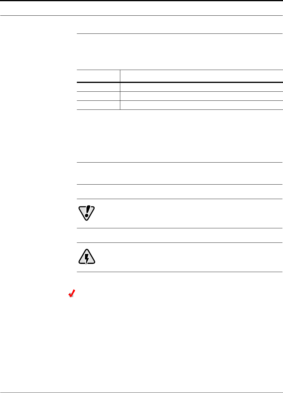
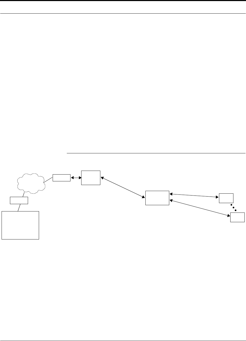
Figure 2-1 OA&M Communications
PSTN
RS-232
RS-232 Ethernet
PC/Laptop
running
Modem
Main Hub
Modem
Main Hub
TCP/IP
RS-232
ENET/232
Converter
Cat-5/6
RS-232
SC/APC
Main Hub
SC/APC
RJ-45
Expansion Hub
RJ-45
Remote Access Unit
Fiber
Main Hub
AdminManager
or OpsConsole
AdminManager can only initiate
communications with a remotely
modem calls.
Use the OpsConsole for monitoring
and receiving communications from
installed system; it cannot receive
remotely installed systems.

PN 8700-10 Help Hot Line (U.S. only): 1-800-530-9960 2-5
620003-0 Rev. A
PRELIMINARY OA&M Software
2.3.1 OA&M Software
The AdminManager software runs on a Laptop PC which is either directly connected
to the DB-9 RS-232 male connector on the Main Hub’s front panel or is remotely
communicating through a modem that is connected to the DB-9 connector on the
Main Hub’s rear panel. The AdminManager communicates with one Main Hub, and
its downstream units, at a time.
• Connected locally, you can access the Installation Wizard which lets you configure
a newly installed system, or access the Configuration Panel which lets you query
system status, configure a newly added or swapped unit, or change system parame-
ters.
• Connected remotely, AdminManager initiates communications with the Main
Hub. You can access a read-only Configuration & Maintenance panel which lets
you check system status to help you determine if an on-site visit is required.
Refer to Section 7 for information about installing and using the AdminManager soft-
ware.
Alternately, an LGC Wireless OA&M software application called the OpsConsole is
available separately. The OpsConsole lets you manage, monitor, and maintain multi-
ple sites and systems from a centralized location. This software is described in the
OpsConsole User Guide, LGC Wireless part number 8701-10.
2.3.2 Configuring, Maintaining, and Monitoring Unison Locally
Each Main Hub, Expansion Hub, and RAU in the system constantly monitors itself
and its downstream units for internal fault and warning conditions. The results of the
monitoring are stored in memory and compared against new results.
The Expansion Hubs monitor their RAUs and store their status in memory. The Main
Hub monitors its Expansion Hubs and stores their status and the status of the RAUs in
its memory. When a unit detects a change in status, a fault or warning is reported.
Faults are indicated locally by red status LEDs, and faults and warnings are reported
to the Main Hub and displayed on a PC/laptop, via the Main Hub’s serial port, that is
running the AdminManager software.
Using AdminManager locally, you can install a new system or new components,
change system parameters, and query system status. The following figure illustrates
how the system reports its status to AdminManager.
InterReach™ Unison System Description PRELIMINARY
2-6 InterReach Unison User Guide and Reference Manual PN 8700-10
620003-0 Rev. A
Figure 2-2 Local System Monitoring and Reporting
Main
Hub
Expansion
Hub
The Main Hub checks its own status and polls each of its
Expansion Hubs for their status, which includes RAU status.
The Expansion Hub checks its own status
and polls each of its RAUs for their status.
Each RAU reports its status to
the Expansion Hub.
• If a fault is detected, the
ALARM LED is red. If no fault
is detected, the LED is green.
• If a fault or warning condition
is detected, the information is
passed to the Expansion
Hub.
The Expansion Hub
receives status from
each of its RAUs and compares
it to previously stored status.
• LEDs on the front panel of the
Expansion Hub light red if a fault
is detected in itself or an RAU.
• If a fault or warning condition is
detected in the Expansion Hub
or an RAU, the information is
passed to the Main Hub.
The Main Hub receives
status of the Expansion Hubs
and each of their RAUs, and
compares it to previously
stored status.
• LEDs on the front panel of
the Main Hub light red if a
fault is detected in any unit.
• If a fault or warning condi-
tion is detected in any unit,
the Main Hub reports it to
the AdminManager.
PC/Laptop
running
AdminManager
Use the Admin-
Manager to query
units for their status
or get current warn-
ing and alarm con-
ditions.
RAU
RAU
PN 8700-10 Help Hot Line (U.S. only): 1-800-530-9960 2-7
620003-0 Rev. A
PRELIMINARY Monitoring and Maintaining Unison Remotely
2.3.3 Monitoring and Maintaining Unison Remotely
• Using AdminManager Remotely
You can use AdminManager to query Unison status via a read-only Configuration
& Maintenance panel. You cannot change system parameters or configure system
components remotely with AdminManager. (Refer to Figure 2-1 on page 2-4.)
• Using OpsConsole Remotely
When monitoring the system remotely, any change of state within the system
causes the Main Hub to initiate an automatic call-out and report the system status
to the OpsConsole. If the host does not acknowledge the connection, the Main Hub
issues an automatic call-out every 15 minutes until an auto acknowledge or stan-
dard request for status (initiated by the host) is received.
Refer to the OpsConsole User Guide, LGC Wireless part number 8701-10, for
more information about using the OpsConsole for system monitoring.
The following figure illustrates how the system reports its status to AdminManager
and the OpsConsole.
Figure 2-3 Remote System Monitoring and Reporting
Expansion
Hub
The Expansion Hub checks its own status
and polls each of its RAUs for their status.
Each RAU reports its status to
the Expansion Hub.
• If a fault is detected, the
ALARM LED is red. If no fault
is detected, the LED is green.
• If a fault or warning condition
is detected, the information is
passed to the Expansion
Hub.
The Expansion Hub
receives status from
each RAU and compares
it to previously stored status.
• If a fault is detected, LEDs on
the front panel light red.
• If a fault or warning condition
is detected in the Expansion
Hub or an RAU, the informa-
tion is passed to the Main
Hub.
The Main Hub receives
status of Expansion Hub
and each RAU and com-
pares it to previously
stored status.
• If a fault is detected,
LEDs on the front panel
light red.
• If a fault or warning con-
dition is detected in any
unit, the Main Hub ini-
tiates a call to the
OpsConsole.
Use the OpsConsole to
remotely monitor and
maintain multiple systems.
OpsConsole sends an
email and/or page notifica-
tion when a change in sys-
tem status is detected.
Use AdminManager to
query status of a single
system (Main Hub and all
of its downstream units)
and determine if a site visit
is required.
RAU
RAU
Modem
Modem
Main
Hub
PC
running
OpsConsole
The Main Hub checks its own status and polls each of its
Expansion Hubs for their status, which includes RAU status.
or AdminManager
PSTN

InterReach™ Unison System Description PRELIMINARY
2-8 InterReach Unison User Guide and Reference Manual PN 8700-10
620003-0 Rev. A
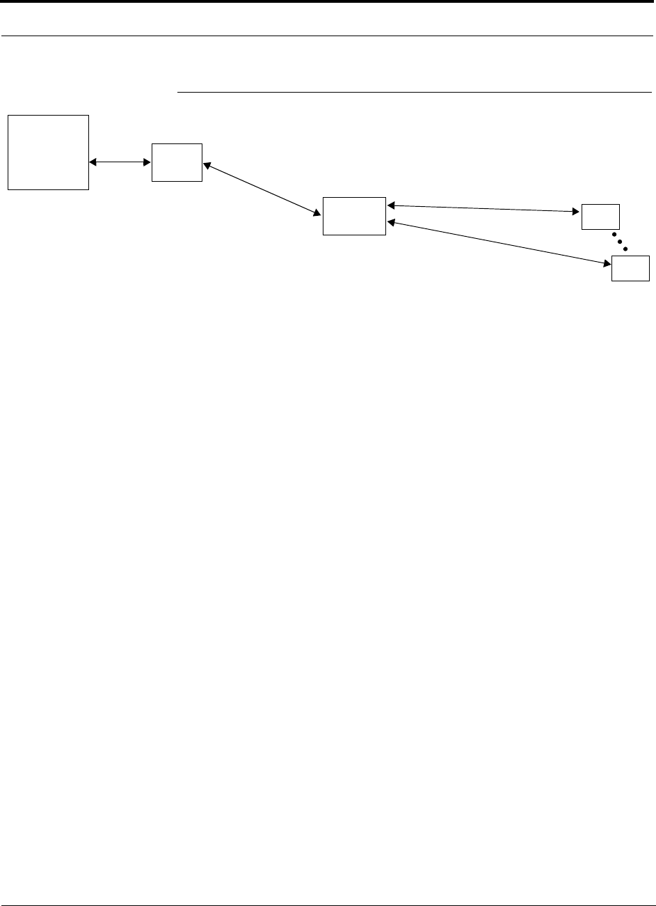
2.3.4 Using Alarm Contact Closures
The DB-9 female connector on the rear panel of the Main Hub can be connected to a
local base station or to a daisy-chained series of Unison, LGCell, and/or MetroReach
Focus systems.
• When you connect MetroReach Focus or a BTS to Unison, the Unison Main Hub
is the output of the alarms (alarm source) and Focus is the input (alarm sense).
• When you connect LGCell to Unison, the Unison Main Hub is the input of the
alarms (alarm sense) and the LGCell is the output (alarm source).
Refer to Section 6.7 on page 6-37 for information on how to connect other equipment
to a Unison system for monitoring.
PN 8700-10 Help Hot Line (U.S. only): 1-800-530-9960 2-9
620003-0 Rev. A
PRELIMINARY System Connectivity
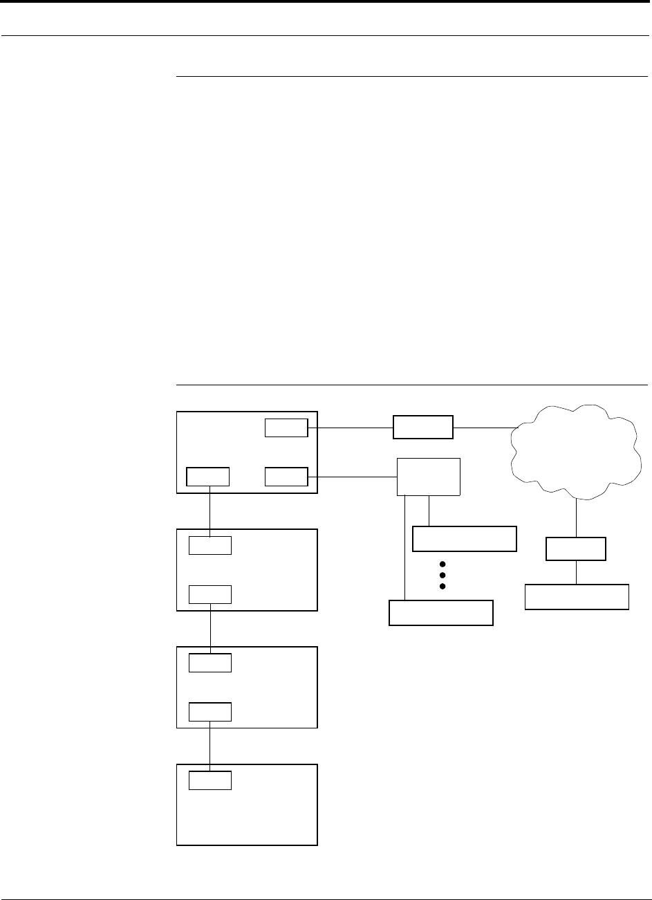
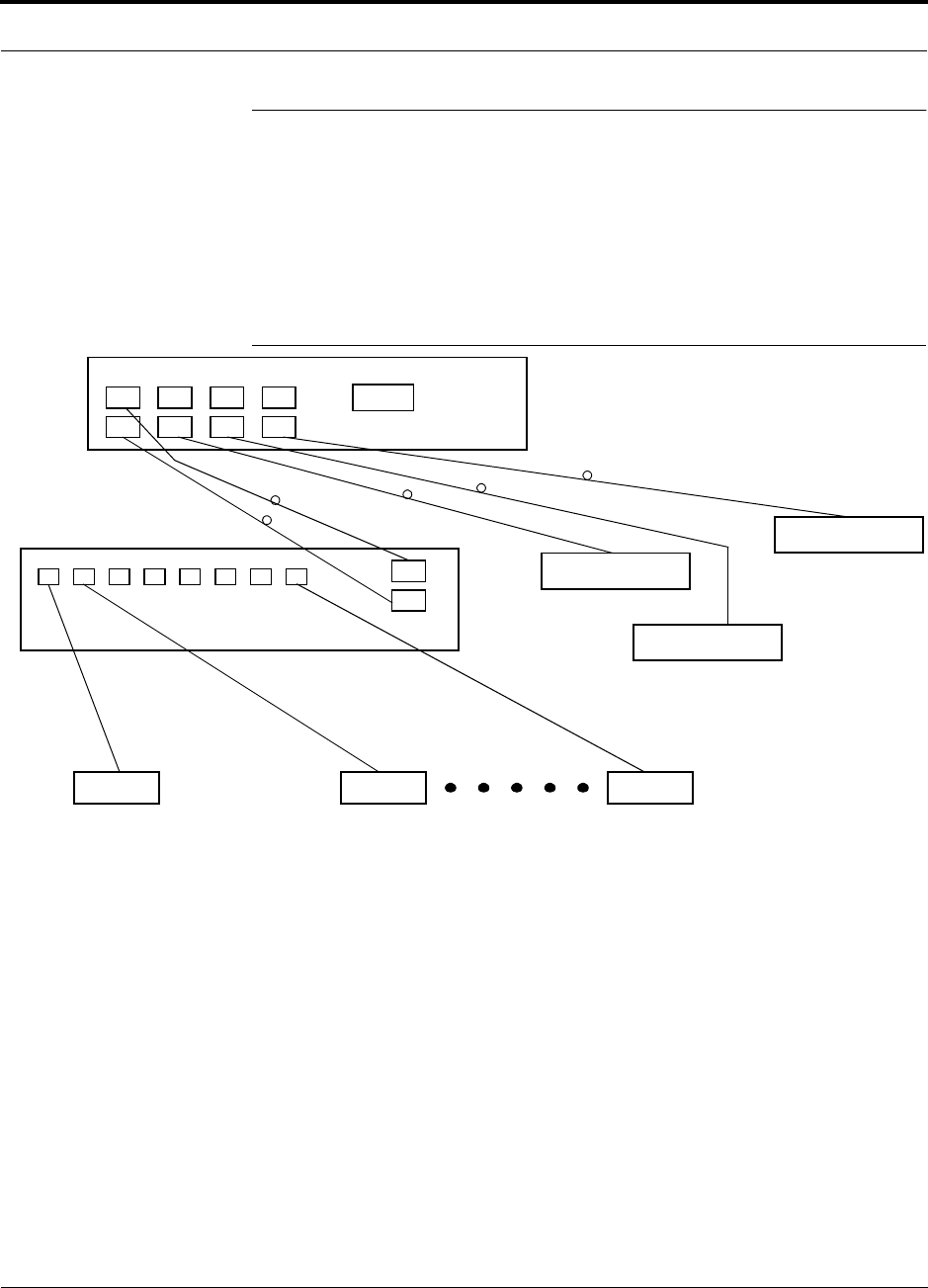
2.4 System Connectivity
The double star architecture of the Unison system, illustrated in the following figure,
provides excellent system scalability and reliability. The system requires only one
pair of fiber for 8 antenna points. This makes any system expansion, such as adding
an extra antenna for additional coverage, potentially as easy as pulling an extra
twisted pair (instead of pulling additional fiber).
Figure 2-4 Unison’s Double Star Architecture
Main Hub
RS-232
PORT 1 PORT 2 PORT 3 PORT 4
Expansion Hub Expansion Hub
Fiber
Expansion Hub
Expansion Hub
Cat-5/6Cat-5/6 Cat-5/6
up to 8 RAUs per Expansion Hub
RAU RAU RAU
InterReach™ Unison System Description PRELIMINARY
2-10 InterReach Unison User Guide and Reference Manual PN 8700-10
620003-0 Rev. A
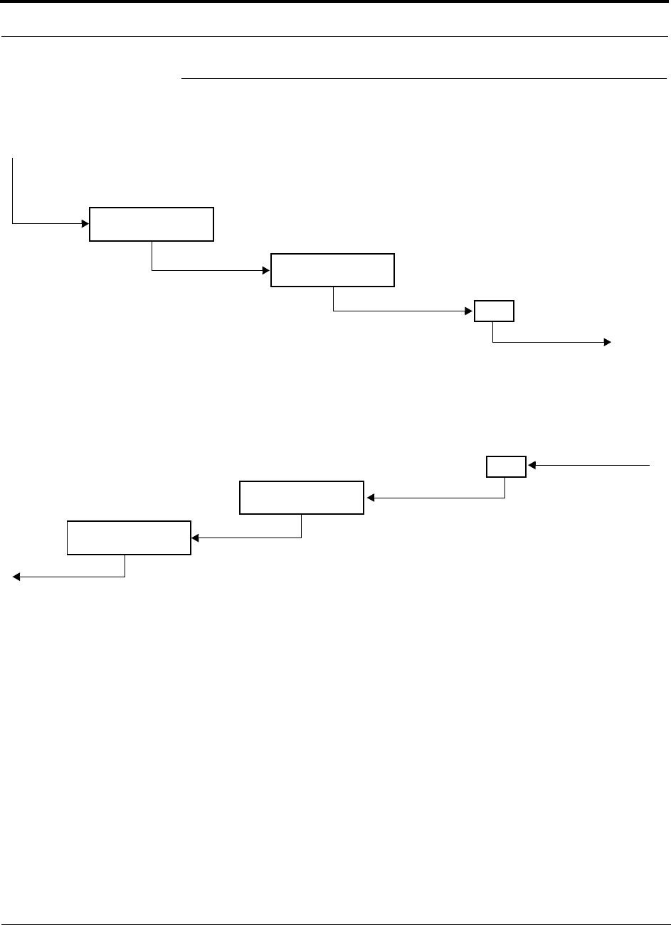
2.5 System Operation
• Downlink (Base Station to Wireless Devices)
• Uplink (Wireless Devices to Base Station)
Main Hub
RAU
The Main Hub receives downlink RF signals
from a base station via coaxial cable
The Main Hub converts the RF signals to IF, then
to optical signals and sends them to Expansion
Hubs (up to four) via optical fiber cable.
The Expansion Hub converts the optical sig-
nals to electrical signals and sends them to
RAUs (up to eight) via Cat-5/6 cable.
The RAU converts the IF signals
to RF and sends them to passive
antennas via coaxial cable.
Expansion Hub
Main Hub
RAU
The Main Hub sends
uplink RF signals to a
base station via coaxial
cable
The Main Hub receives
the optical signals from
the Expansion Hubs (up
to four) via optical fiber
cables and converts
them to RF signals.
The Expansion Hub
receives the IF signals
from the RAUs (up to
eight) via Cat-5/6
cables and converts
them to optical signals.
The RAU receives uplink RF
signals from the passive
antenna via coaxial cable and
converts them to IF signals.
Expansion Hub

PN 8700-10 Help Hot Line (U.S. only): 1-800-530-9960 2-11
620003-0 Rev. A
PRELIMINARY System Specifications
2.6 System Specifications
2.6.1 Physical Specifications
Parameter Main Hub Expansion Hub Remote Antenna Unit
RF Connectors 2 N-type, female 8 shielded RJ-45, female
(Cat-5/6)
1 shielded RJ-45, female
(Cat-5/6)
1 SMA, male (coaxial)
External Alarm Connector
(contact closure)
1 9-pin D-sub, female — —
Serial Interface Connector 1 9-pin D-sub, male — —
Fiber Connectors 4 Pair, SC/APC 1 Pair, SC/APC —
LED Alarm and
Status Indicators
Unit Status (1 pair):
•Power
• Main Hub Status
Downstream Unit Status
(1 pair per fiber port):
•Link
•E-Hub/RAU
Unit Status (1 pair):
•Power
•E-Hub Status
Fiber Link Status (1 pair):
•DL Status
•UL Status
RAU/Link Status
(1 pair per RJ-45 port):
•Link
•RAU
Unit Status (1 pair):
•Link
•Alarm
AC Power (Volts) Rating: 100–240V, 0.5A,
50–60 Hz
Operating Range: 85–250V,
2.4–0.8A, 47–63 Hz
Rating: 115/230V, 5/2.5A,
50–60 Hz
Operating Range:
90–132V/170–250V
auto-ranging,
2.2–1.5A/1.2–0.8A, 47–63 Hz
—
DC Power (Volts) — — 36V (from the Expansion
Hub)
Power Consumption (W) 30 260 (includes 8 RAUs) 11
Enclosure Dimensions*
(height × width × depth)
*Excluding angle-brackets for 19'' rack mounting of hubs.
44.5 mm × 438 mm × 305 mm
(1.75 in. × 17.25 in. × 12 in.)
89 mm × 438 mm × 305 mm
(3.5 in. × 17.25 in. × 12 in.)
44 mm × 305 mm × 158 mm
(1.7 in. × 12 in. × 6.2 in.)
Weight < 3 kg
(< 6.5 lb)
< 5 kg
(< 11 lb)
< 1 kg
(< 2 lb)
MTBF 106,272 hours 78,998 hours 282,207 hours

InterReach™ Unison System Description PRELIMINARY
2-12 InterReach Unison User Guide and Reference Manual PN 8700-10
620003-0 Rev. A
2.6.2 Environmental Specifications
2.6.3 Operating Frequencies
Parameter Main Hub and Expansion Hub RAU
Operating Temperature 0° to +45°C (+32° to +113°F) –25° to +45°C (–13° to +113°F)
Non-operating Temperature –20° to +85°C (–4° to +185°F) –25° to +85°C (–13° to +185°F)
Operating Humidity; non-condensing 5% to 95% 5% to 95%
Freq.
Band Unison
Band Description
RF Passband
Downlink (MHz) Uplink (MHz)
PCS PCS1 A & D Band 1930–1950 1850–1870
PCS PCS2 D & B Band 1945–1965 1865–1885
PCS PCS3 B & E Band 1950–1970 1870–1890
PCS PCS4 E & F Band 1965–1975 1885–1895
PCS PCS5 F & C Band 1970–1990 1890–1910
DCS DCS1 DCS1 Band 1805–1842.5 1710–1747.5
DCS DCS2 DCS2 Band 1842.5–1880 1747.5–1785
DCS DCS3 DCS3 Band 1840–1875 1745–1780
Cellular CELL – 869–894 824–849
iDEN iDEN – 851–869 806–824
EGSM EGSM – 925–960 880–915
GSM GSM – 935–960 890–915
UMTS UMTS1 – 2110–2145 1920–1955
UMTS UMTS2 – 2125–2160 1935–1970
UMTS UMTS3 – 2135–2170 1945–1980

PN 8700-10 Help Hot Line (U.S. only): 1-800-530-9960 2-13
620003-0 Rev. A
PRELIMINARY RF End-to-End Performance
2.6.4 RF End-to-End Performance
Cellular
Table 2-1 Cellular RF End-to-End Performance using 2 km of Single-Mode
Fiber
Parameter
Typical
Downlink Uplink
Average gain with 75 m Cat-5/6 at 25°C (77°F)*
*The system gain is adjustable in 1 dB steps from 0 to 15 dB, and the gain of each RAU can be attenuated 10 dB in one step.
15 dB 15 dB
Ripple with 75 m Cat-5/6 3 dB 3.5 dB
Output IP3 40 dBm
Input IP3†
†For two tones into one RAU, IP3 higher in other circumstances.
–7 dBm
Output 1 dB Compression Point 27 dBm
AMPS output power per carrier when 30 carriers are present 0.7 dBm
TDMA output power per carrier when 16 carriers are present 4.0 dBm
CDMA output power per carrier when 6 carriers are present 7.8 dBm
Noise Figure with 1 MH – 1 EH – 8 RAUs configuration 15 dB
Noise Figure with 1 MH – 4 EHs – 32 RAUs configuration 21 dB
Table 2-2 Cellular RF End-to-End Performance using 1 km of Multimode Fiber
Parameter
Typical
Downlink Uplink
Average gain with 75 m Cat-5/6 at 25°C (77°F)*
*The system gain is adjustable in 1 dB steps from 0 to 15 dB, and the gain of each RAU can be attenuated 10 dB in one step.
15 dB 15 dB
Ripple with 75 m Cat-5/6 3 dB 3.5 dB
Output IP3 37 dBm
Input IP3†
†For two tones into one RAU, IP3 higher in other circumstances.
–10 dBm
Output 1 dB Compression Point 27 dBm
AMPS output power per carrier when 30 carriers are present 0.7 dBm
TDMA output power per carrier when 16 carriers are present 4.0 dBm
CDMA output power per carrier when 6 carriers are present 7.8 dBm
Noise Figure with 1 MH – 1 EH – 8 RAUs configuration 15 dB
Noise Figure with 1 MH – 4 EHs – 32 RAUs configuration 21 dB

InterReach™ Unison System Description PRELIMINARY
2-14 InterReach Unison User Guide and Reference Manual PN 8700-10
620003-0 Rev. A
iDEN
GSM
Table 2-3 iDEN RF End-to-End Performance using 2 km of Single-Mode Fiber
Parameter
Typical
Downlink Uplink
Average gain with 75 m Cat-5/6 at 25°C (77°F)*
*The system gain is adjustable in 1 dB steps from 0 to 15 dB, and the gain of each RAU can be attenuated 10 dB in one step.
15 dB 15 dB
Ripple with 75 m Cat-5/6 2 dB 3 dB
Output IP3 38 dBm
Input IP3 –16 dBm
Output 1 dB Compression Point 26 dBm
Output power per carrier when 6 carriers are present 6.4 dBm
Noise Figure with 1 MH – 1 EH – 8 RAUs configuration 17 dB
Noise Figure with 1 MH – 4 EHs – 32 RAUs configuration 23 dB
Table 2-4 GSM RF End-to-End Performance using 2 km of Single-Mode Fiber
Parameter
Typical
Downlink Uplink
Average gain with 75 m Cat-5/6 at 25°C (77°F)*
*The system gain is adjustable in 1 dB steps from 0 to 15 dB, and the gain of each RAU can be attenuated 10 dB in one step.
15 dB 15 dB
Ripple with 75 m Cat-5/6 2 dB 3 dB
Output IP3 38 dBm
Input IP3 –16 dBm
Output 1 dB Compression Point 26 dBm
GSM output power per carrier when 12 carriers are present 5.0 dBm
Noise Figure with 1 MH – 1 EH – 8 RAUs configuration 17 dB
Noise Figure with 1 MH – 4 EHs – 32 RAUs configuration 23 dB

PN 8700-10 Help Hot Line (U.S. only): 1-800-530-9960 2-15
620003-0 Rev. A
PRELIMINARY RF End-to-End Performance
EGSM
Table 2-5 EGSM RF End-to-End Performance using 2 km of Single-Mode Fiber
Parameter
Typical
Downlink Uplink
Average gain with 75 m Cat-5/6 at 25°C (77°F)*
*The system gain is adjustable in 1 dB steps from 0 to 15 dB, and the gain of each RAU can be attenuated 10 dB in one step.
15 dB 15 dB
Ripple with 75 m Cat-5/6 3 dB 4 dB
Output IP3 38 dBm
Input IP3 –7 dBm
Output 1 dB Compression Point 26 dBm
Noise Figure with 1 MH – 1 EH – 8 RAU configuration 16 dB
Noise Figure with 1 MH – 4 EH – 32 RAU configuration 22 dB
Table 2-6 EGSM RF End-to-End Performance using 1 km of Multimode Fiber
Parameter
Typical
Downlink Uplink
Average gain with 75 m Cat-5/6 at 25°C (77°F)*
*The system gain is adjustable in 1 dB steps from 0 to 15 dB, and the gain of each RAU can be attenuated 10 dB in one step.
15 dB 15 dB
Ripple with 75 m Cat-5/6 3 dB 4 dB
Output IP3 38 dBm
Input IP3 –10 dBm
Output 1 dB Compression Point 26 dBm
Noise Figure with 1 MH – 1 EH – 8 RAUs configuration 16 dB
Noise Figure with 1 MH – 4 EHs – 32 RAUs configuration 22 dB

InterReach™ Unison System Description PRELIMINARY
2-16 InterReach Unison User Guide and Reference Manual PN 8700-10
620003-0 Rev. A
DCS
Table 2-7 DCS RF End-to-End Performance using 2 km of Single-Mode Fiber
Parameter
Typical
Downlink Uplink
Average gain with 75 m Cat-5/6 at 25°C (77°F)*
*The system gain is adjustable in 1 dB steps from 0 to 15 dB, and the gain of each RAU can be attenuated 10 dB in one step.
15 dB 15 dB
DCS1 & DCS2 Ripple with 75 m Cat-5/6 2.5 dB 5 dB
DCS3 & center 35MHz of DCS or DCS2 Ripple with 75 m
Cat-5/6
2 dB 2 dB
Output IP3 37 dBm
Input IP3 –15 dBm
Output 1 dB Compression Point 25 dBm
Noise Figure with 1 MH – 1 EH – 8 RAUs configuration 17 dB
Noise Figure with 1 MH – 4 EHs – 32 RAUs configuration 23 dB
Table 2-8 DCS RF End-to-End Performance using 1 km of Multimode Fiber
Parameter
Typical
Downlink Uplink
Average gain with 75 m Cat-5/6 at 25°C (77°F)*
*The system gain is adjustable in 1 dB steps from 0 to 15 dB, and the gain of each RAU can be attenuated 10 dB in one step.
15 dB 15 dB
DCS1 & DCS2 Ripple with 75 m Cat-5/6 2.5 dB 5 dB
DCS3 & center 35MHz of DCS or DCS2 Ripple with 75 m
Cat-5/6
2 dB 2 dB
Output IP3 37 dBm
Input IP3 –17 dBm
Output 1 dB Compression Point 25 dBm
Noise Figure with 1 MH – 1 EH – 8 RAUs configuration 17 dB
Noise Figure with 1 MH – 4 EHs – 32 RAUs configuration 23 dB

PN 8700-10 Help Hot Line (U.S. only): 1-800-530-9960 2-17
620003-0 Rev. A
PRELIMINARY RF End-to-End Performance
PCS
Table 2-9 PCS RF End-to-End Performance using 2 km of Single-Mode Fiber
Parameter
Typical
Downlink Uplink
Average gain with 75 m Cat-5/6 at 25°C (77°F)*
*The system gain is adjustable in 1 dB steps from 0 to 15 dB, and the gain of each RAU can be attenuated 10 dB in one step..
15 dB 15 dB
Ripple with 75 m Cat-5/6 2.5 dB 3 dB
Output IP3 38 dBm
Input IP3 –12 dBm
Output 1 dB Compression Point 26 dBm
TDMA output power per carrier when 16 carriers are present 4.0 dBm
GSM output power per carrier when 16 carriers are present 4.2 dBm
CDMA output power per carrier when 8 carriers are present 7.8 dBm
Noise Figure with 1 MH – 1 EH – 8 RAUs configuration 16 dB
Noise Figure with 1 MH – 4 EHs – 32 RAUs configuration 22 dB
Table 2-10 PCS RF End-to-End Performance using 1 km of Multimode Fiber
Parameter
Typical
Downlink Uplink
Average gain with 75 m Cat-5/6 at 25°C (77°F)*
*The system gain is adjustable in 1 dB steps from 0 to 15 dB, and the gain of each RAU can be attenuated 10 dB in one step..
15 dB 15 dB
Ripple with 75 m Cat-5/6 2.5 dB 3 dB
Output IP3 36.5 dBm
Input IP3 –14 dBm
Output 1 dB Compression Point 26 dBm
TDMA output power per carrier when 16 carriers are present 4.0 dBm
GSM output power per carrier when 16 carriers are present 4.2 dBm
CDMA output power per carrier when 8 carriers are present 7.8 dBm
Noise Figure with 1 MH – 1 EH – 8 RAUs configuration 16 dB
Noise Figure with 1 MH – 4 EHs – 32 RAUs configuration 22 dB

InterReach™ Unison System Description PRELIMINARY
2-18 InterReach Unison User Guide and Reference Manual PN 8700-10
620003-0 Rev. A
WCDMA
Table 2-11 WCDMA RF End-to-End Performance using 2 km of Single-Mode
Fiber
Parameter
Typical
Downlink Uplink
Average gain with 75 m Cat-5/6 at 25°C (77°F) *
*The system gain is adjustable in 1 dB steps from 0 to 15 dB, and the gain of each RAU can be attenuated 10 dB in one step.
15 dB 15 dB
Ripple with 75 m Cat-5/6 3 dB 3 dB
Output IP3 36.5 dBm
Input IP3 –12 dBm
Output 1 dB Compression Point 26 dBm
Output power per carrier when 7 carriers are present 4.5 dBm
Noise Figure with 1 MH – 1 EH – 8 RAUs configuration 16 dB
Noise Figure with 1 MH – 4 EHs – 32 RAUs configuration 22 dB
PN 8700-10 InterReach Unison User Guide and Reference Manual 3-1
620003-0 Rev. A
PRELIMINARY
SECTION 3 Unison Main Hub
The Main Hub distributes downlink RF signals from a base station, repeater, or
MetroReach Focus system to up to four Expansion Hubs, which in turn distribute the
signals to up to 32 Remote Access Units. The Main Hub also combines uplink signals
from the Expansion Hubs for a base station or MetroReach Focus system.
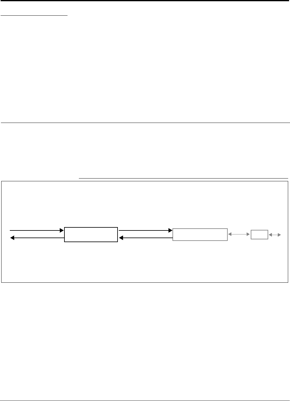
Figure 3-1 Main Hub in a Unison System
Unison Main Hub Unison Expansion Hub RAU
Downlink Path: The Main Hub receives downlink RF signals from a base station, repeater, or MetroReach Focus system
via coaxial cable. It converts the signals to optical and sends them to up to four Expansion Hubs via fiber optic cables.
The Main Hub also sends OA&M communication to the Expansion Hubs via the fiber optic cable. The Expansion Hubs, in
turn, communicate the OA&M information to the RAUs via Cat-5/6 cable.
Uplink Path: The Main Hub receives uplink optical signals from up to four Expansion Hubs via fiber optic cables. It converts
the signals to RF and sends them to a base station, repeater, or MetroReach Focus system via coaxial cable.
The Main Hub also receives status information from the Expansion Hubs and all RAUs via the fiber optic cable.
Downlink to Main Hub
Uplink from Main Hub
Downlink from Main Hub
Uplink to Main Hub
Unison Main Hub PRELIMINARY
3-2 InterReach Unison User Guide and Reference Manual PN 8700-10
620003-0 Rev. A
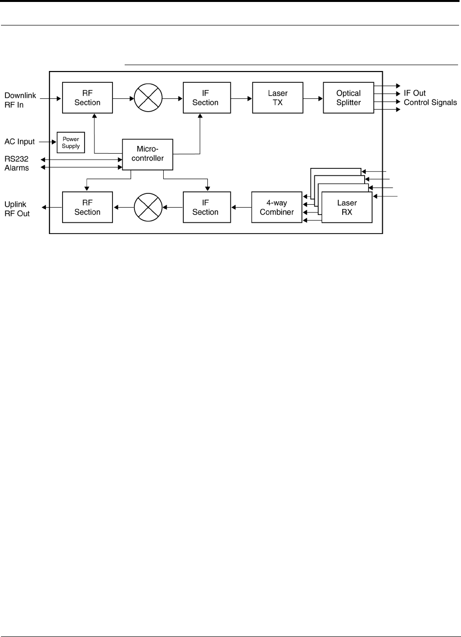
Figure 3-2 Main Hub Block Diagram
IF In
Control Signals

PN 8700-10 Help Hot Line (U.S. only): 1-800-530-9960 3-3
620003-0 Rev. A
PRELIMINARY Main Hub Front Panel
3.1 Main Hub Front Panel
Figure 3-3 Main Hub Front Panel
1. Four fiber optic ports (labeled PORT 1, PORT 2, PORT 3, PORT 4)
• One standard female SC/APC connector per port for MMF/SMF input (labeled
UPLINK)
• One standard female SC/APC connector per port for MMF/SMF output
(labeled DOWNLINK)
2. Four sets of fiber port LEDs (one set per port)
• One LED per port for port link status (labeled LINK)
• One LED per port for downstream unit status (labeled E-HUB/RAU)
3. One set of unit status LEDs
• One LED for unit power status (labeled POWER)
• One LED for unit status (labeled MAIN HUB STATUS)
4. One 9-pin D-sub male connector for system communication and diagnostics using
a PC/laptop (labeled RS-232)
1234
Unison Main Hub PRELIMINARY
3-4 InterReach Unison User Guide and Reference Manual PN 8700-10
620003-0 Rev. A
3.1.1 Optical Fiber Uplink/Downlink Ports
The optical fiber uplink/downlink ports transmit and receive optical signals between
the Main Hub and up to four Expansion Hub(s) using industry-standard SMF or
MMF cable. There are four fiber ports on the front panel of the Main Hub; one port
per Expansion Hub. Each fiber port has two female SC/APC connectors:
• Optical Fiber Uplink Connector
This connector (labeled UPLINK) is used to receive the uplink optical signals from
an Expansion Hub.
• Optical Fiber Downlink Connector
This connector (labeled DOWNLINK) is used to transmit the downlink optical sig-
nals to an Expansion Hub.
CAUTION: To avoid damaging the Main Hub’s fiber connector
ports, use only SC/APC fiber cable connectors.
3.1.2 Communications RS-232 Serial Connector
Remote Monitoring
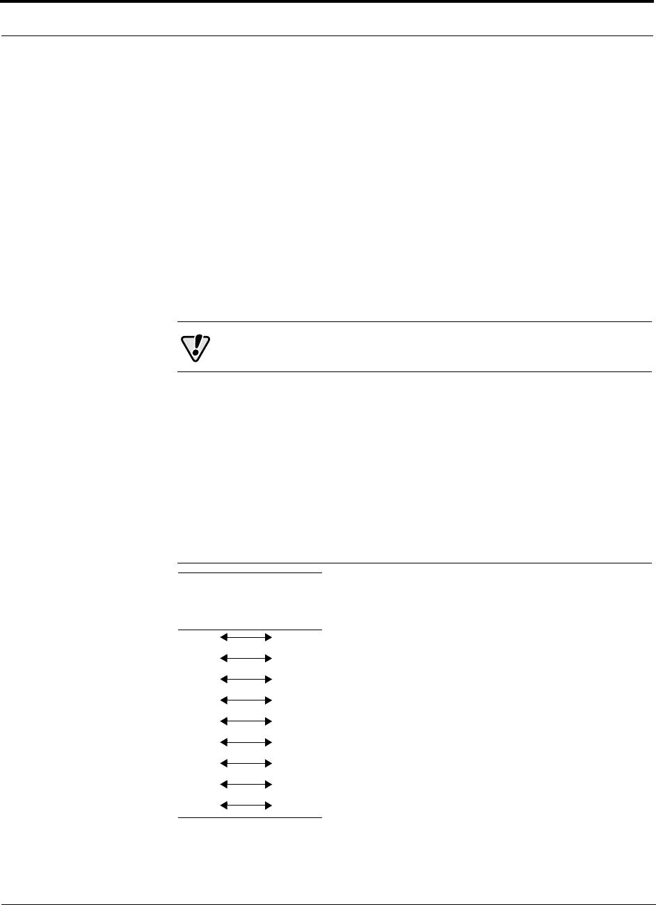
Use a standard serial cable to connect a modem to the 9-pin D-sub male serial con-
nector for remote monitoring or configuring. The cable typically has a DB-9 female
and a DB-25 male connector. The following figure shows the cable pinout.
Figure 3-4 Standard Serial Cable Pinout
DB-9
Connector
Pin
DB-25
Connector
Pin
1
2
3
4
5
6
7
8
9
8
3
2
20
7
6
4
5
22
PN 8700-10 Help Hot Line (U.S. only): 1-800-530-9960 3-5
620003-0 Rev. A
PRELIMINARY Communications RS-232 Serial Connector
Local Monitoring
Use a null modem cable to connect a laptop or PC to the 9-pin D-sub male serial con-
nector for local monitoring or configuring. The cable typically has a DB-9 female
connector on both ends. The following figure shows the cable pinout.
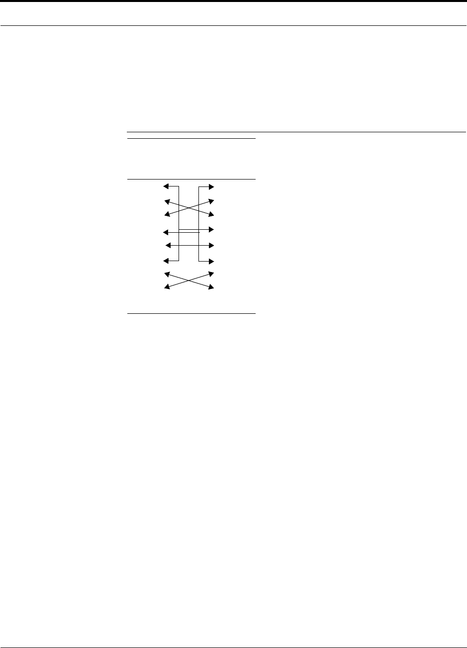
Figure 3-5 Null Modem Cable Pinout
Note that for each connector, pins 1 and 6 are tied together and sent to pin 4 of the
opposite connector.
DB-9
Connector
Pin
DB-9
Connector
Pin
1
2
3
4
5
6
7
8
9
1
2
3
4
5
6
7
8
9
Unison Main Hub PRELIMINARY
3-6 InterReach Unison User Guide and Reference Manual PN 8700-10
620003-0 Rev. A
3.1.3 LED Indicators
The unit’s front panel LEDs indicate fault conditions and commanded or fault lockouts.
The LEDs do not indicate warnings or if the system test has not been performed. Use
the LEDs as a go/no go test or as a backup when you are not using AdminManager.
Upon power up, the Main Hub goes through a five-second test to check the LED
lamps. During this time, the LEDs blink through the states shown in Table 3-2, letting
you visually verify that the LED lamps and the firmware are functioning properly.
NOTE: Refer to Section 10 for troubleshooting using the LEDs.
Unit Status LEDs
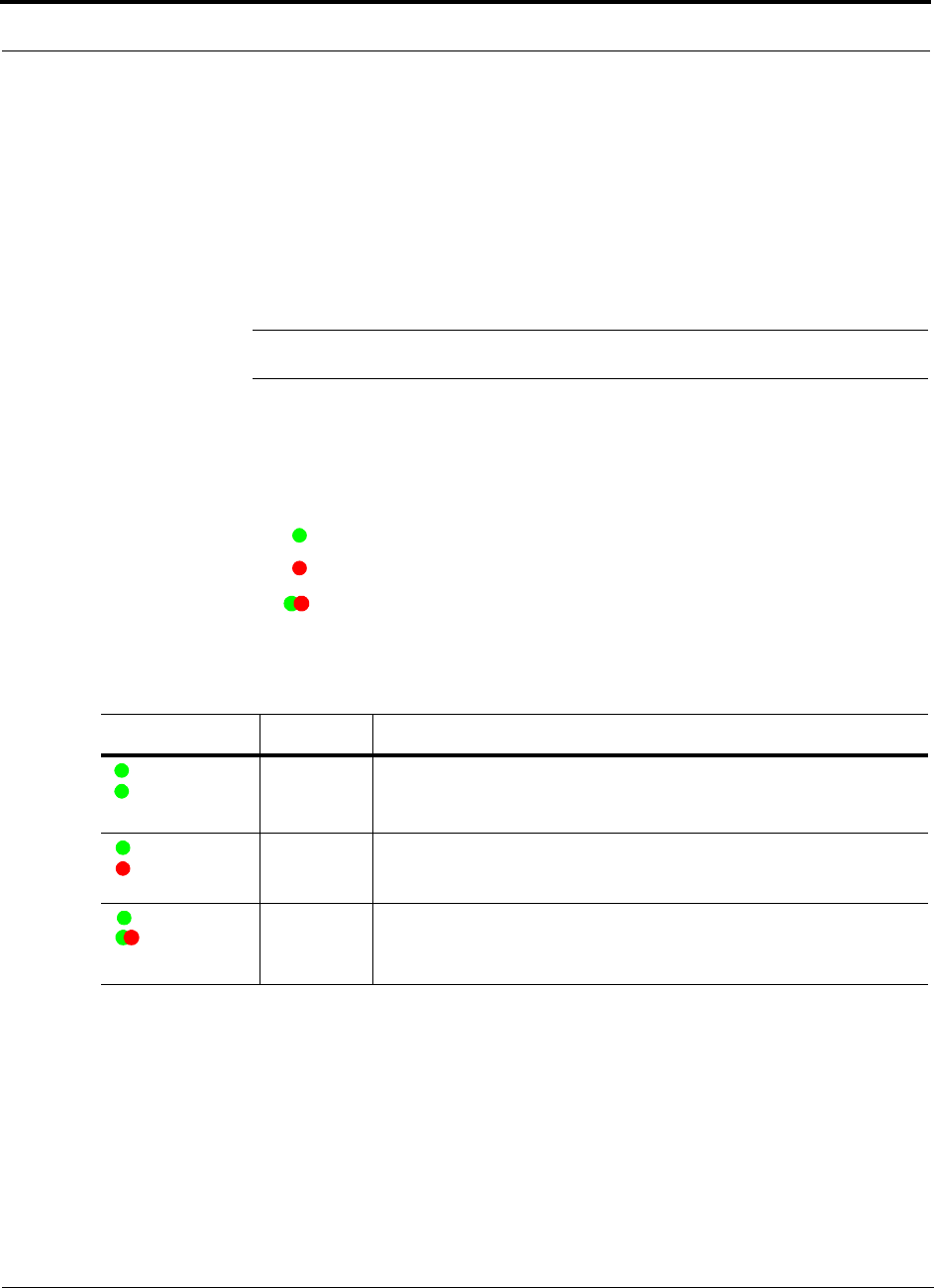
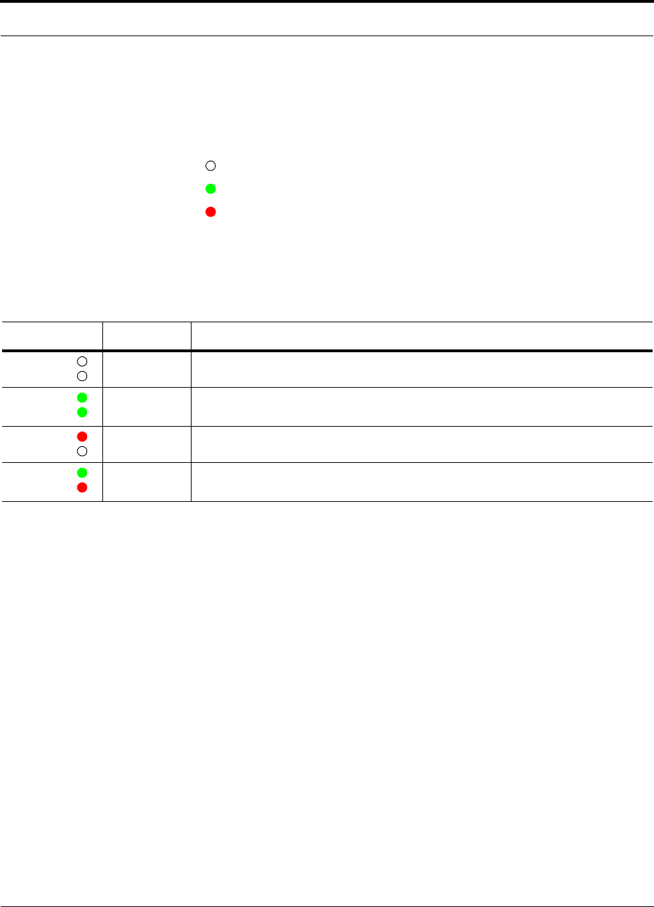
The Main Hub status LEDs can be in one of three states, as shown in Table 3-1.
These LEDs can be:
steady green
steady red
blinking green/red (alternating green/red)
There is no off state when the unit’s power is on.
Table 3-1 Main Hub Status LED States
LED State Indicates
Green
Green
• Main Hub is connected to power
• Main Hub is not reporting a fault; but the system test may need to be
performed or a warning condition could exist
Green
Red
• Main Hub is connected to power
• Main Hub is reporting a fault or lockout condition
Green
Alternating
Green/Red
• Main Hub is connected to power
• Main Hub input signal level too high
POWER
MAIN HUB
STATUS
POWER
MAIN HUB
STATUS
POWER
MAIN HUB
STATUS
PN 8700-10 Help Hot Line (U.S. only): 1-800-530-9960 3-7
620003-0 Rev. A
PRELIMINARY LED Indicators
Port LEDs
The Main Hub has one pair of fiber port LEDs for each of the four Expansion Hub
ports. The LED pairs can be in one of four states, as shown in the following table, in a
combination of the following:
off
steady green
steady red
The port LEDs indicate the status of the Expansion Hub and RAUs; however, they do
not indicate which particular unit is having a problem (i.e., the Expansion Hub vs.
one of the RAUs).
Table 3-2 Main Hub Port LED States
LED State Indicates
Off
Off
• Expansion Hub not connected
Green
Green
• Expansion Hub connected, communications normal
• No faults from Expansion Hub or any connected RAU
Red
Off
• Loss of communications with Expansion Hub
Green
Red
• Expansion Hub connected
• Fault or lockout reported by Expansion Hub or any connected RAU
LINK
E-HUB/RAU
LINK
E-HUB/RAU
LINK
E-HUB/RAU
LINK
E-HUB/RAU
Unison Main Hub PRELIMINARY
3-8 InterReach Unison User Guide and Reference Manual PN 8700-10
620003-0 Rev. A
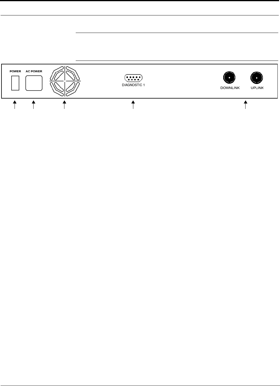
3.2 Main Hub Rear Panel
Figure 3-6 Main Hub Rear Panel
1. Power on/off switch
2. AC power cord connector
3. Fan exhaust vent
4. One 9-pin D-sub female connector for contact closure monitoring (labeled
DIAGNOSTIC 1)
5. Two N-type, female connectors:
• Downlink (labeled DOWNLINK)
• Uplink (labeled UPLINK)
1 2 3 4 5

PN 8700-10 Help Hot Line (U.S. only): 1-800-530-9960 3-9
620003-0 Rev. A
PRELIMINARY Main Hub Rear Panel Connectors
3.2.1 Main Hub Rear Panel Connectors
3.2.1.1 N-type Female Connectors
There are two N-type female connectors on the rear panel of the Main Hub:
•The
UPLINK connector transmits uplink RF signals to a repeater, local base sta-
tion, or MetroReach Focus system.
•The
DOWNLINK connector receives downlink RF signals from a repeater, local
base station, or MetroReach Focus system.
3.2.1.2 9-pin D-sub Connector
The 9-pin D-sub connector (labeled DIAGNOSTIC 1) provides contact closure for
major error and minor error system alarm monitoring.
The following table lists the function of each pin on the 9-pin D-sub connector. Pin
locations are labeled on the figure.
This interface can either generate contact alarms or sense a single external alarm con-
tact.
Pin Function
1 Ground / Alarm Input
2 Reserved
3 Reserved
4 Minor Error (positive connection)
5 Minor Error (negative connection)
6 DC Ground (common)
7 Major Error (positive connection)
8 Alarm Input
9 Major Error (negative connection)

Unison Main Hub PRELIMINARY
3-10 InterReach Unison User Guide and Reference Manual PN 8700-10
620003-0 Rev. A
3.3 Faults and Warnings
The Main Hub monitors and reports changes in system performance to:
• Ensure that Expansion Hubs and Remote Access Units are connected and function-
ing properly.
• Ensure that the fiber receivers, amplifiers, and IF/RF path in the Main Hub are
functioning properly.
The Main Hub periodically polls attached Expansion Hubs and their Remote Access
Units for status. Both fault and warning conditions are reported to a connected
PC/laptop that is running the AdminManager software or to the optional remote
OpsConsole. Only faults are indicated by LEDs.
The faults and warnings that the Main Hub is responsible for monitoring and report-
ing are listed in Section 10.

PN 8700-10 Help Hot Line (U.S. only): 1-800-530-9960 3-11
620003-0 Rev. A
PRELIMINARY Main Hub Specifications
3.4 Main Hub Specifications
Table 3-3 Main Hub Specifications
Specification Description
Enclosure Dimensions (H × W × D): 44.5 mm × 438 mm × 305 mm
(1.75 in. × 17.25 in. × 12 in.)
Weight < 3 kg (< 6.5 lb)
Operating Temperature 0° to +45°C (+32° to +113°F)
Non-operating Temperature –20° to +85°C (–4° to +185°F)
Operating Humidity, non-condensing 5% to 95%
External Alarm Connector
(contact closure)
1 9-pin D-sub, female
Serial Interface Connector 1 9-pin D-sub, male
Fiber Connectors 4 Pair, SC/APC
RF Connectors 2 N-type, female
LED Fault and Status Indicators Unit Status (1 pair):
•Power
• Main Hub Status
Downstream Unit/Link Status (1 pair per fiber port):
•Link
•E-Hub/RAU
AC Power Rating: 100–240V, 0.5A, 50–60 Hz
Operating Range: 85–250V, 2.4–0.8A, 47–63 Hz
Power Consumption (W) 30
MTBF 106,272 hours

Unison Main Hub PRELIMINARY
3-12 InterReach Unison User Guide and Reference Manual PN 8700-10
620003-0 Rev. A
PN 8700-10 InterReach Unison User Guide and Reference Manual 4-1
620003-0 Rev. A
PRELIMINARY
SECTION 4 Unison Expansion Hub
The Expansion Hub interfaces between the Main Hub and the Remote Access Unit(s)
by converting optical signals to electrical signals. It also supplies the DC power to
operate the Remote Access Unit(s).
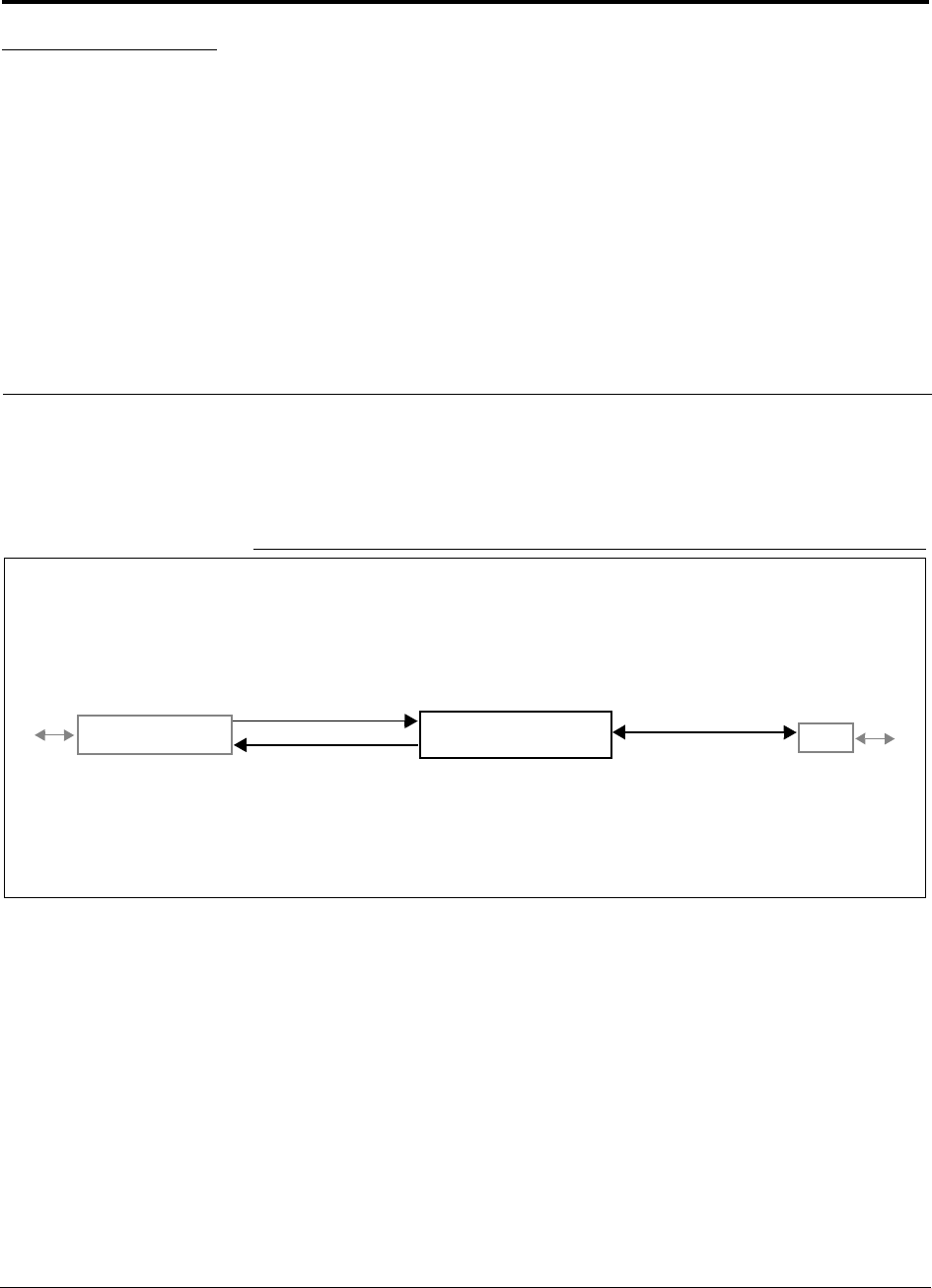
Figure 4-1 Expansion Hub in a Unison System
Unison Expansion Hub
Unison Main Hub RAU
Downlink Path: The Expansion Hub receives downlink optical signals from the Main Hub via fiber optic cable. It converts
the signals to electrical and sends them to up to eight Remote Access Units (RAUs) via Cat-5/6 cables.
Also, the Expansion Hub receives configuration information from the Main Hub via the fiber optic cable and relays configu-
ration information to the RAUs via the Cat-5/6 cable.
Uplink Path: The Expansion Hub receives uplink IF signals from up to eight RAUs via Cat-5/6 cables. It converts the sig-
nals to optical and sends them to a Main Hub via fiber optic cable.
Also, the Expansion Hub receives RAU status information via the Cat-5/6 cable and sends it and its own status information
to the Main Hub via the fiber optic cable.
Downlink to Expansion Hub
Uplink from Expansion Hub
Downlink from Expansion Hub
Uplink to Expansion Hub
Unison Expansion Hub PRELIMINARY
4-2 InterReach Unison User Guide and Reference Manual PN 8700-10
620003-0 Rev. A
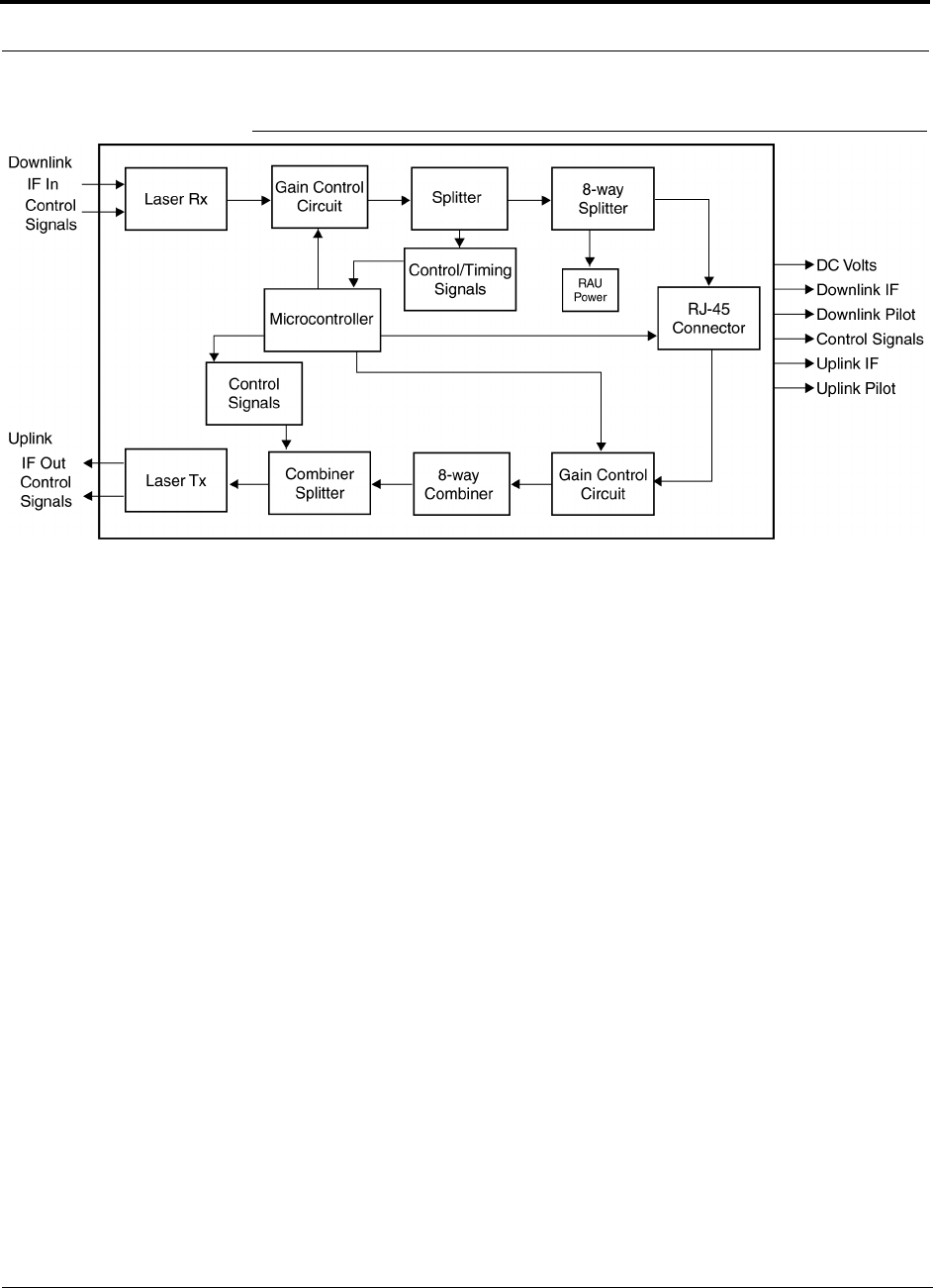
Figure 4-2 Expansion Hub Block Diagram
PN 8700-10 Help Hot Line (U.S. only): 1-800-530-9960 4-3
620003-0 Rev. A
PRELIMINARY Expansion Hub Front Panel
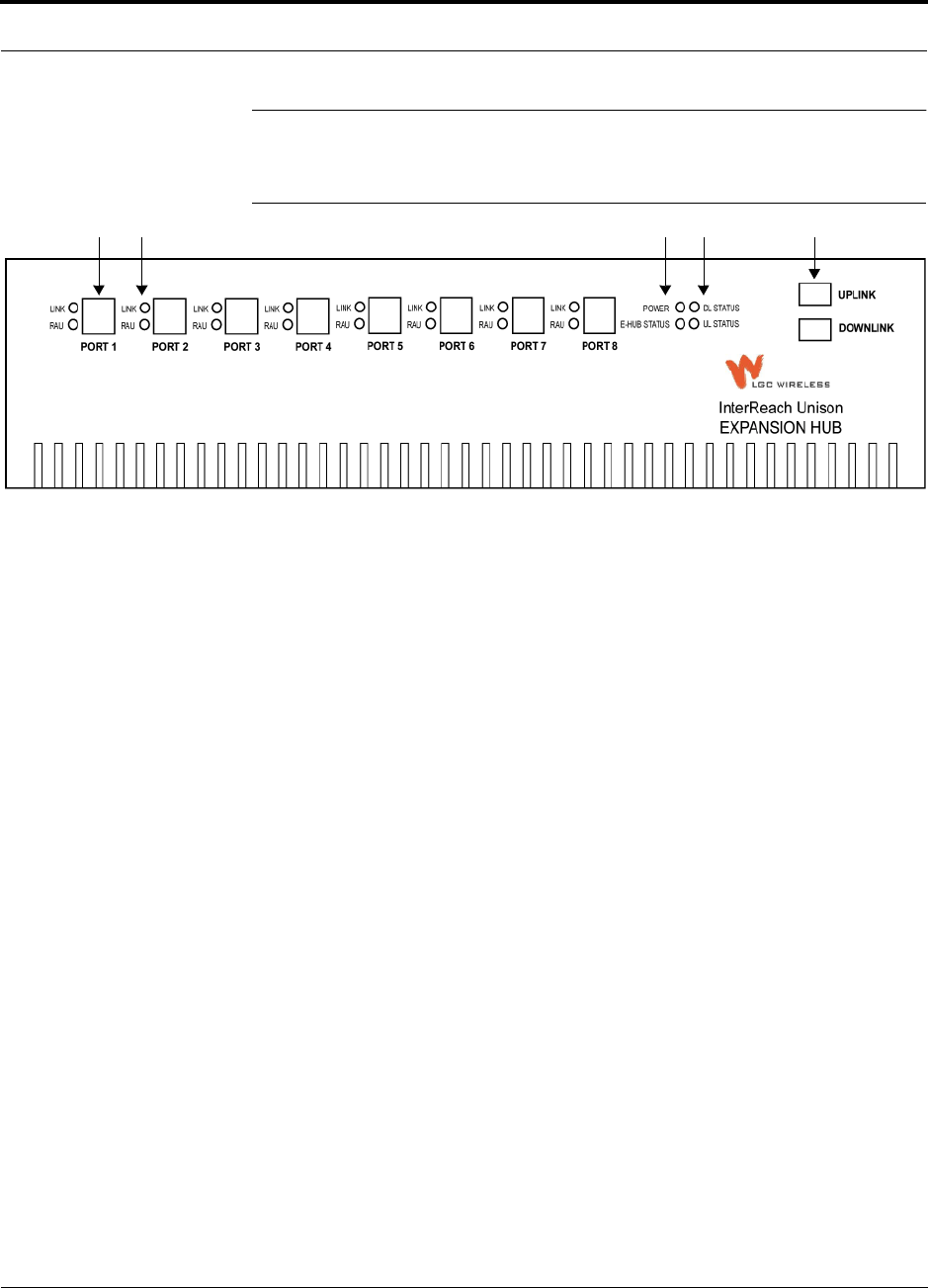
4.1 Expansion Hub Front Panel
Figure 4-3 Expansion Hub Front Panel
1. Eight standard Cat-5/6 ScTP cable RJ-45 connectors (labeled PORT 1, 2, 3, 4, 5, 6,
7, 8)
2. Eight sets of RJ-45 port LEDs (one set per port)
• One LED per port for link status (labeled LINK)
• One LED per port for downstream unit status (labeled RAU)
3. One set of unit status LEDs
• One LED for unit power status (labeled POWER)
• One LED for unit status (labeled E-HUB STATUS)
4. One set of fiber connection status LEDs
• One LED for fiber downlink status (labeled DL STATUS)
• One LED for fiber uplink status (labeled UL STATUS)
5. One fiber optic port which has two connectors
• One standard female SC/APC connector for MMF/SMF input (labeled UPLINK)
• One standard female SC/APC connector for MMF/SMF output (labeled DOWN-
LINK)
1 2 3 4 5

Unison Expansion Hub PRELIMINARY
4-4 InterReach Unison User Guide and Reference Manual PN 8700-10
620003-0 Rev. A
4.1.1 RJ-45 Connectors
The eight RJ-45 connectors on the Expansion Hub are for the Cat-5/6 ScTP cable that
is used to transmit and receive signals to and from RAUs. Use shielded RJ-45 con-
nectors on the Cat-5/6 cable.
The Cat-5/6 cable also delivers DC electrical power to the RAUs. The Expansion
Hub’s DC voltage output is 36V DC nominal. A current limiting circuit is used to
protect the Expansion Hub if any port draws excessive power.
4.1.2 Optical Fiber Uplink/Downlink Connectors
The optical fiber uplink/downlink port transmits and receives optical signals between
the Expansion Hub and the Main Hub using industry-standard SMF or MMF cable.
The fiber port has two female SC/APC connectors:
• Optical Fiber Uplink Connector
This connector (labeled UPLINK) is used to transmit (output) uplink optical signals
to the Main Hub.
• Optical Fiber Downlink Connector
This connector (labeled DOWNLINK) is used to receive (input) downlink optical sig-
nals from the Main Hub.
CAUTION: To avoid damaging the Expansion Hub’s fiber con-
nector port, use only SC/APC fiber cable connectors.
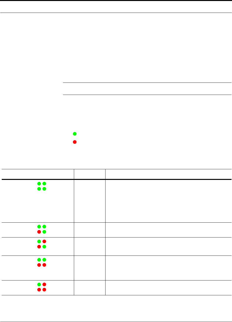
PN 8700-10 Help Hot Line (U.S. only): 1-800-530-9960 4-5
620003-0 Rev. A
PRELIMINARY LED Indicators
4.1.3 LED Indicators
The unit’s front panel LEDs indicate fault conditions and commanded or fault lockouts.
The LEDs do not indicate warnings or if the system test has not been performed. Use
the LEDs as a go/no go test or as a backup when you are not using AdminManager.
Upon power up, the Expansion Hub goes through a five-second test to check the LED
lamps. During this time, the LEDs blink through the states shown in Table 4-2, letting
you visually verify that the LED lamps and the firmware are functioning properly.
NOTE: Refer to Section 10 for troubleshooting using the LEDs.
Unit Status and DL/UL Status LEDs
The Expansion Hub unit status and DL/UL status LEDs can be in one of five states,
as shown in the following table. These LEDs can be:
steady green
steady red
There is no off state when the unit’s power is on.
Table 4-1 Expansion Hub Unit Status and DL/UL Status LED States
LED State Indicates
Green / Green
Green / Green
• Expansion Hub is connected to power
• Expansion Hub is not reporting a fault or lockout; but the system
test may need to be performed or a warning condition could exist
• Optical power in is above minimum (Main Hub is connected)
although the cable length may be longer than recommended
maximum
• Optical power out (uplink laser) is normal
Green / Green
Red / Green
• Expansion Hub is reporting a fault or commanded lockout, but
optical power in and out are normal
Green / Red
Red / Green
• Fault condition detected, optical power in is below minimum.
(Main Hub is not connected, is not powered, or Main Hub’s DL
laser has failed.)
Green / Green
Red / Red
• Expansion Hub is reporting a fault condition
• Optical power in is normal, optical power out is below minimum
(Expansion Hub uplink laser has failed; unable to communicate
with Main Hub)
Green / Red
Red / Red
• No downlink or uplink: replace Expansion Hub
POWER
E-HUB STATUS DL STATUS
UL STATUS
POWER
E-HUB STATUS DL STATUS
UL STATUS
POWER
E-HUB STATUS DL STATUS
UL STATUS
POWER
E-HUB STATUS DL STATUS
UL STATUS
POWER
E-HUB STATUS DL STATUS
UL STATUS
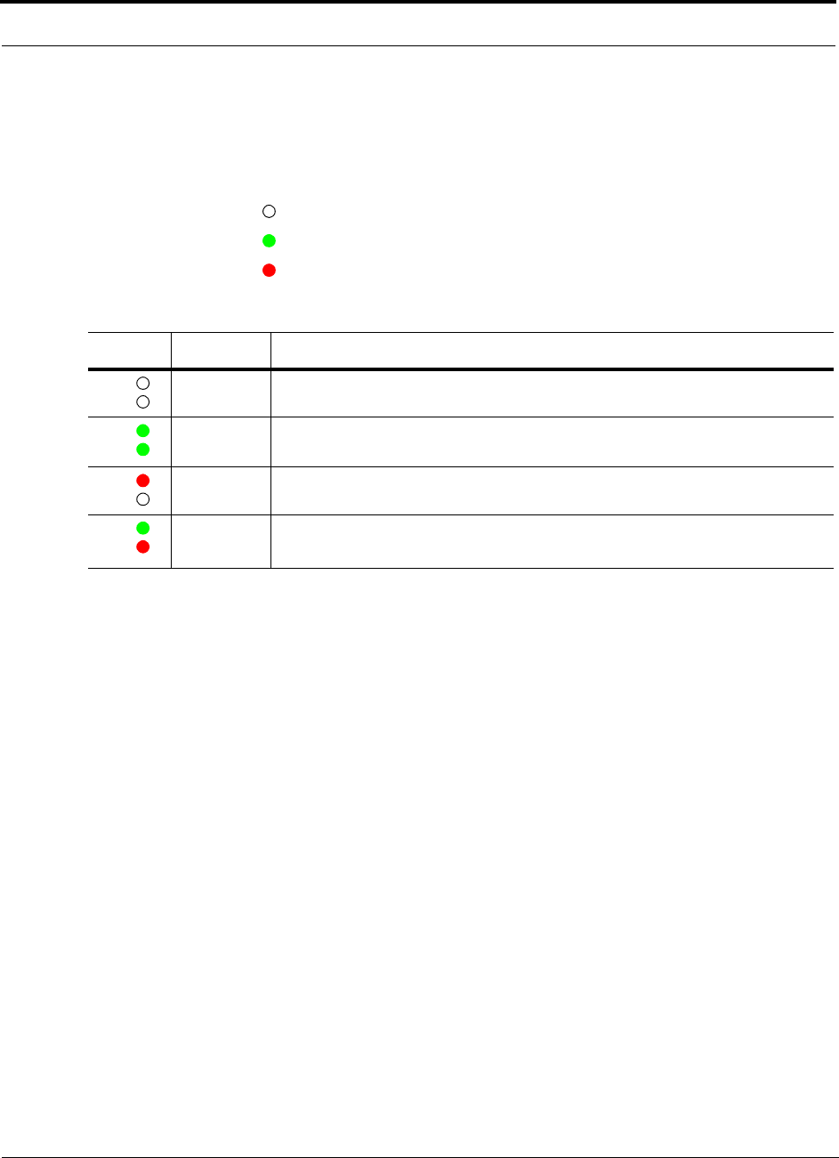
Unison Expansion Hub PRELIMINARY
4-6 InterReach Unison User Guide and Reference Manual PN 8700-10
620003-0 Rev. A
Port LEDs
The Expansion Hub has one pair of port LEDs for each of the eight RJ-45 ports. The
port LEDs can be in one of four states, as shown in the following table. These LEDs
can be:
off
steady green
steady red
Table 4-2 Expansion Hub Port LED States
LED State Indicates
Off
Off
• RAU is not connected
Green
Green
• RAU is connected
• No faults from RAU
Red
Off
• Loss of communications to RAU
Green
Red
• RAU is connected
• Fault/lockout condition reported by RAU
LINK
RAU
LINK
RAU
LINK
RAU
LINK
RAU
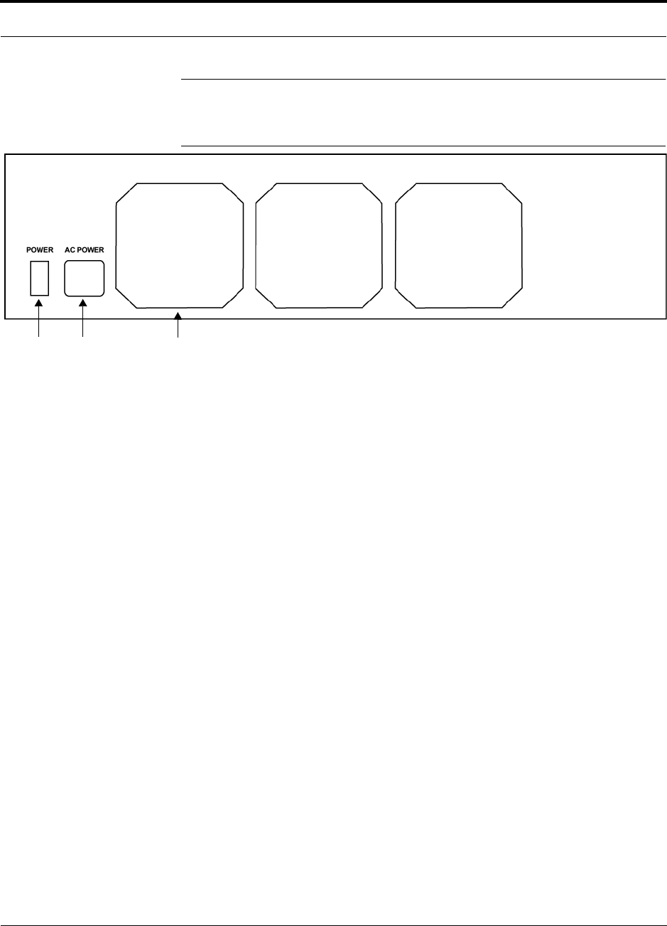
PN 8700-10 Help Hot Line (U.S. only): 1-800-530-9960 4-7
620003-0 Rev. A
PRELIMINARY Expansion Hub Rear Panel
4.2 Expansion Hub Rear Panel
Figure 4-4 Expansion Hub Rear Panel
1. Power on/off switch
2. AC power cord connector
3. Three air exhaust vents
1 2 3

Unison Expansion Hub PRELIMINARY
4-8 InterReach Unison User Guide and Reference Manual PN 8700-10
620003-0 Rev. A
4.3 Faults and Warnings
The Main Hub periodically polls attached Expansion Hubs and their Remote Access
Units for status. Both fault and warning conditions are reported to a connected
PC/laptop that is running the AdminManager software or to the optional remote
OpsConsole. Only faults are indicated by LEDs.
The faults and warnings that the Expansion Hub is responsible for monitoring and
Reporting are listed in Section 10.

PN 8700-10 Help Hot Line (U.S. only): 1-800-530-9960 4-9
620003-0 Rev. A
PRELIMINARY Expansion Hub Specifications
4.4 Expansion Hub Specifications
Table 4-3 Expansion Hub Specifications
Specification Description
Enclosure Dimensions (H × W × D) 89 mm × 438 mm × 305 mm
(3.5 in. × 17.25 in. × 12 in.)
Weight < 5 kg (< 11 lb)
Operating Temperature 0° to +45°C (+32° to +113°F)
Non-operating Temperature –20° to +85°C (–4° to +185°F)
Operating Humidity, non-condensing 5% to 95%
Cat-5/6 Connectors 8 shielded RJ-45, female (Cat-5/6)
Fiber Connectors 1 Pair, SC/APC
LED Alarm and Status Indicators Unit Status (1 pair):
•Power
• E-Hub Status
Fiber Link Status (1 pair):
•DL Status
•UL Status
RAU/Link Status (1 pair per RJ-45 port):
•Link
•RAU
AC Power (Volts) (47–63 Hz) Rating: 115/230V, 5/2.5A, 50–60 Hz
Operating Range: 90–132V/170–250V auto-ranging,
2.2–1.5A/1.2–0.8A, 47–63 Hz
Power Consumption (W) 260 (includes 8 RAUs)
MTBF 78,998 hours

Unison Expansion Hub PRELIMINARY
4-10 InterReach Unison User Guide and Reference Manual PN 8700-10
620003-0 Rev. A
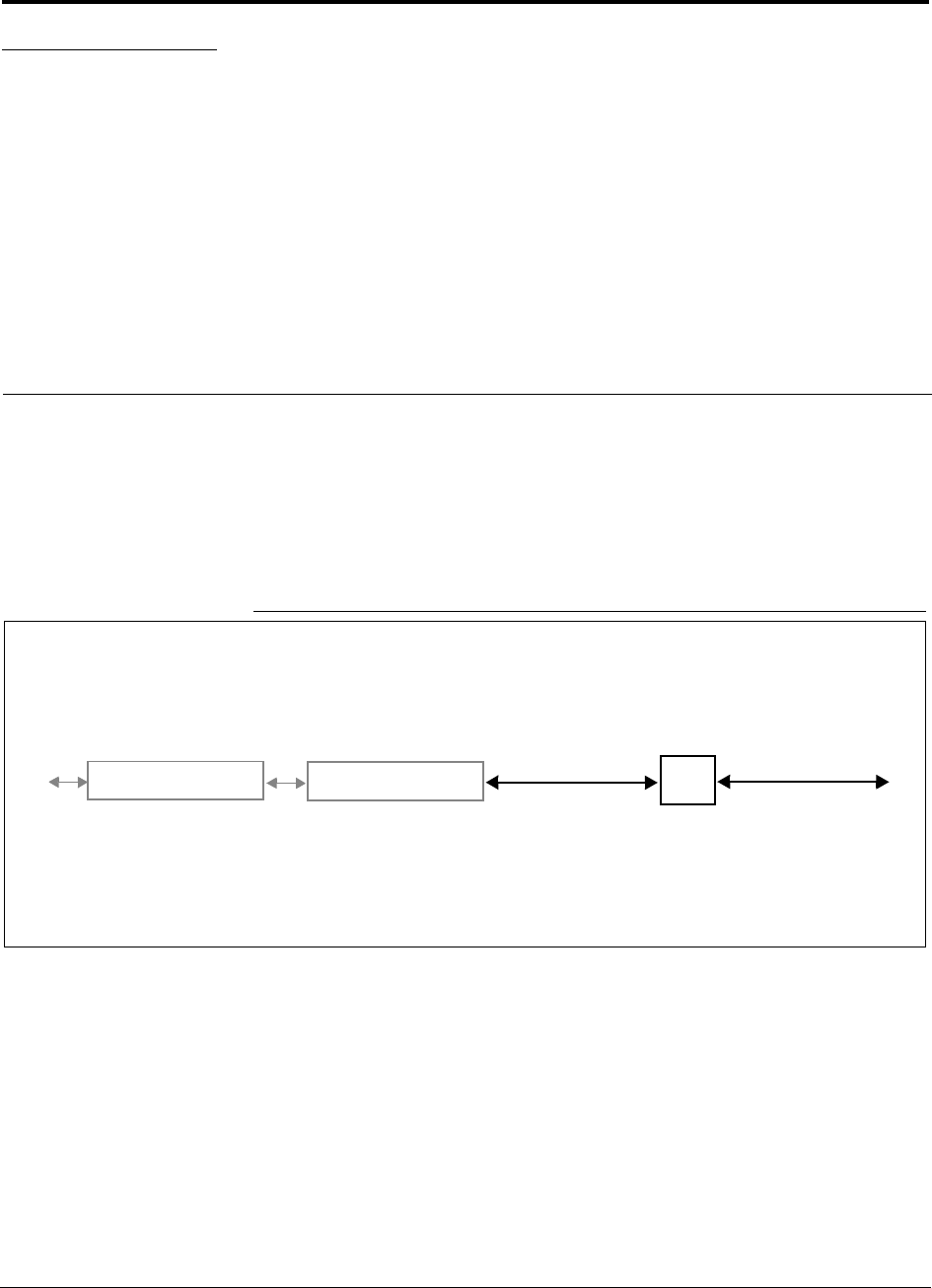
PN 8700-10 InterReach Unison User Guide and Reference Manual 5-1
620003-0 Rev. A
PRELIMINARY
SECTION 5 Unison Remote Access Unit
The Remote Access Unit (RAU) is an active transceiver that connects to an Expan-
sion Hub using industry-standard Cat-5/6 ScTP cable. The cable also delivers electri-
cal power to the RAU.
An RAU passes RF signals between an Expansion Hub and an attached passive
antenna where the signals are transmitted to wireless devices.
Figure 5-1 Remote Access Unit in a Unison System
Unison Expansion Hub RAU
Downlink Path: The RAU receives downlink IF signals from an Expansion Hub via Cat-5/6 cable. It converts the signals to
RF and sends them to a passive RF antenna via coaxial cable.
Also, the RAU receives configuration information from the Main Hub via the Cat-5/6 cable.
Uplink Path: The RAU receives uplink RF signals from a passive RF antenna via coaxial cable. It converts the signals to IF
and sends them to an Expansion Hub via Cat-5/6 cable.
Also, the RAU sends its status information to the Expansion Hub via the Cat-5/6 cable.
Downlink to RAU
Uplink from RAU
Unison Main Hub Downlink to antenna
Uplink from antenna
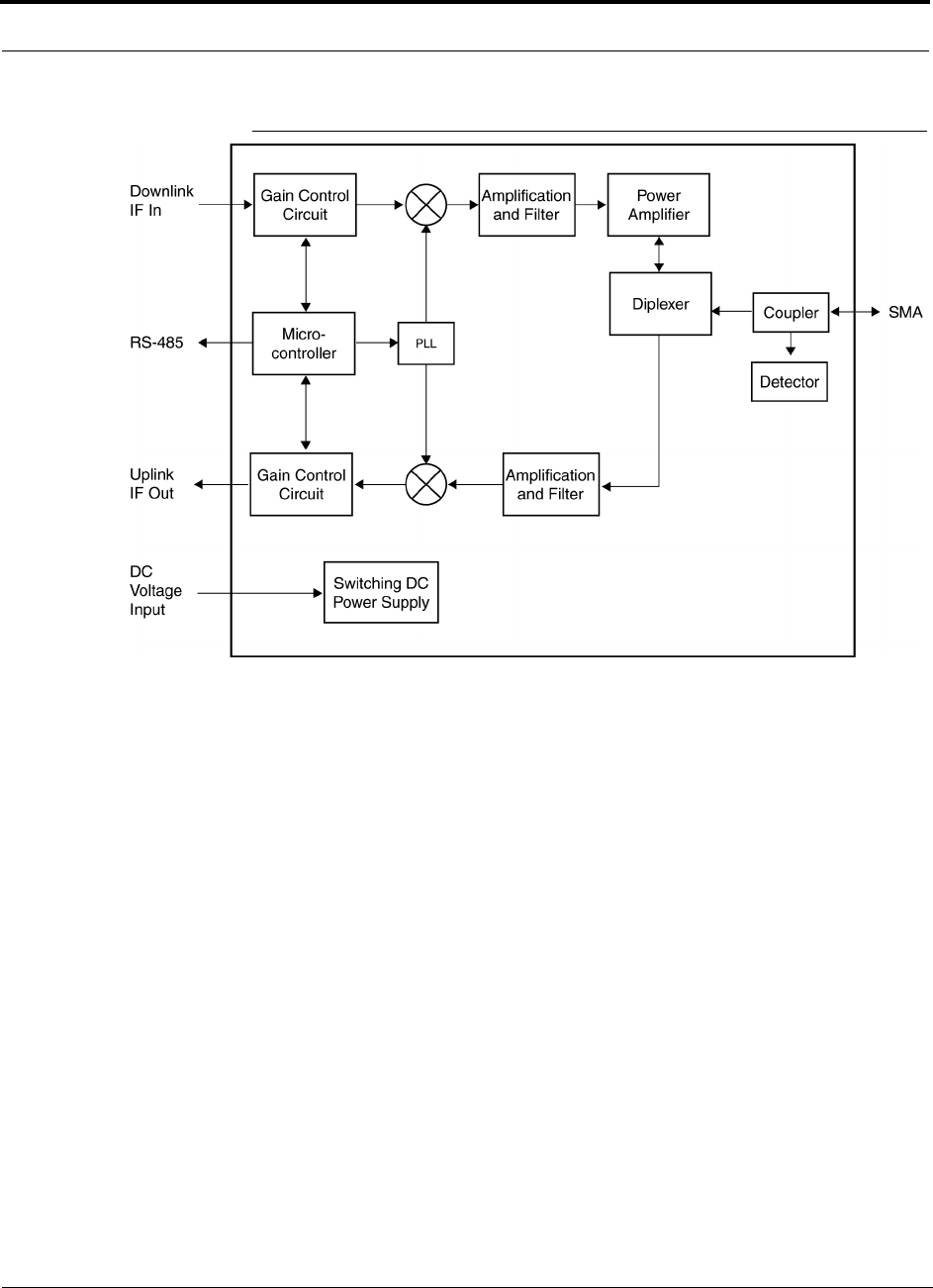
Unison Remote Access Unit PRELIMINARY
5-2 InterReach Unison User Guide and Reference Manual PN 8700-10
620003-0 Rev. A
Figure 5-2 Remote Access Unit Block Diagram
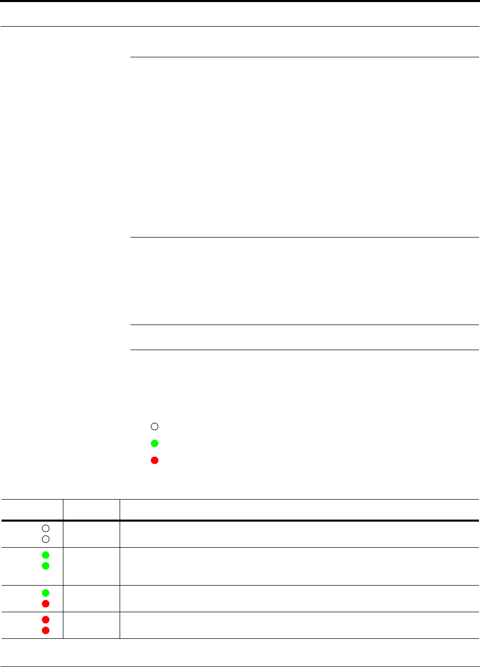
PN 8700-10 Help Hot Line (U.S. only): 1-800-530-9960 5-3
620003-0 Rev. A
PRELIMINARY Remote Access Unit Connectors
5.1 Remote Access Unit Connectors
5.1.1 SMA Connector
The RAU has one female SMA connector. The connector is a duplexed RF input/out-
put port that connects to a standard passive antenna using coaxial cable.
5.1.2 RJ-45 Port
The RAU has one RJ-45 port that connects it to an Expansion Hub using Cat-5/6
ScTP cable. Use shielded RJ-45 connectors on the Cat-5/6 cable.
5.2 LED Indicators
Upon power up, the RAU goes through a two-second test to check the LED lamps.
During this time, the LEDs blink through the states shown in Table 5-1, letting you
visually verify that the LED lamps and the firmware are functioning properly.
NOTE: Refer to Section 10 for troubleshooting using the LEDs.
Status LEDs
The RAU status LEDs can be in one of four states, as shown in the following table.
These LEDs can be:
off
steady green
steady red
Table 5-1 Remote Access Unit LED States
LED State Indicates
Off
Off
• RAU is not receiving DC power
Green
Green
• RAU is powered and is not indicating a fault condition. Communication with Expansion
Hub is normal; but the system test may need to be performed or a warning condition could
exist (use AdminManager to determine)
Green
Red
• RAU is indicating a fault or lockout condition, but communication with the Expansion Hub
is normal
Red
Red
• RAU is reporting a fault or lockout condition, and it is not able to communicate with the
Expansion Hub
LINK
ALARM
LINK
ALARM
LINK
ALARM
LINK
ALARM

Unison Remote Access Unit PRELIMINARY
5-4 InterReach Unison User Guide and Reference Manual PN 8700-10
620003-0 Rev. A
5.3 Faults and Warnings
The Main Hub periodically polls attached Expansion Hubs and their Remote Access
Units for status. Both faults and warning conditions are reported to a connected
PC/laptop that is running the AdminManager software, or to the optional remote
OpsConsole. Only faults are indicated by LEDs.
The faults and warnings that the RAU is responsible for monitoring and reporting are
listed in Section 10.

PN 8700-10 Help Hot Line (U.S. only): 1-800-530-9960 5-5
620003-0 Rev. A
PRELIMINARY Remote Access Unit Specifications
5.4 Remote Access Unit Specifications
Table 5-2 Remote Access Unit Specifications
Specification Description
Dimensions (H × W × D) 44 mm × 305 mm × 158 mm
(1.7 in. × 12 in. × 6.2 in.)
Weight < 1 kg (< 2 lb)
Operating Temperature –25° to +45°C (–13° to +113°F)
Non-operating Temperature –25° to +85°C (–13° to +185°F)
Operating Humidity, non-condensing 5% to 95%
RF Connectors 1 shielded RJ-45, female (Cat-5/6)
1 SMA, male (coaxial)
LED Alarm and Status Indicators Unit Status (1 pair): • Link • Alarm
Maximum Heat Dissipation (W) 11
MTBF 282,207 hours

Unison Remote Access Unit PRELIMINARY
5-6 InterReach Unison User Guide and Reference Manual PN 8700-10
620003-0 Rev. A

PN 8700-10 InterReach Unison User Guide and Reference Manual 6-1
620003-0 Rev. A
PRELIMINARY
SECTION 6 Installing Unison Components
6.1 Installation Requirements
6.1.1 Component Location Requirements
Unison components are intended to be installed in indoor locations only.
6.1.2 Cable and Connector Requirements
The Unison equipment operates over standard Category 5 or 6 (Cat-5/6) screened
twisted pair (ScTP) and industry-standard single-mode fiber (SMF) or multimode
fiber (MMF) cable.
These cables are widely used industry standards for Local Area Networks (LANs).
The regulations and guidelines for Unison cable installation are identical to those
specified by the TIA/EIA 568-A standard and the TIA/EIA/IS-729 supplement for
LANs.
LGC Wireless recommends plenum-rated Cat-5/6 ScTP and fiber cable and connec-
tors for conformity to building codes and standards. ScTP is required in order to meet
FCC and CE Mark emissions requirements.
6.1.3 Neutral Host System Requirements
As in any Unison system, a neutral host system requires one pair of fiber strands
between each Main Hub and each Expansion Hub, and one Cat-5/6 cable between
each Expansion Hub and each RAU. To help achieve the cost savings possible in a
neutral host system, it is advantageous to install additional cables for future growth.

Installing Unison Components PRELIMINARY
6-2 InterReach Unison User Guide and Reference Manual PN 8700-10
620003-0 Rev. A
6.1.4 Distance Requirements
The following table shows the distances between Unison components and related
equipment.
Table 6-1 Unison Distance Requirements
Equipment
Combination Cable Type Distance Additional Information
Repeater to Main Hub Coaxial; N male
connectors
3–6 m (10–20 ft) typical Limited by loss and noise.
Refer to your link budget
calculation.
Base Station to Main Hub Coaxial; N male
connectors
3–6 m (10–20 ft) typical Limited by loss and noise.
Refer to your link budget
calculation.
Main Hub to
Expansion Hub
Multimode Fiber:
Single-Mode Fiber:
SC/APC male
connectors
1.5 km (4,921 ft) max.
6 km (19,685 ft) max.
Limited by 3 dB optical loss.
Expansion Hub to RAU Cat-5/6 ScTP;
shielded RJ-45 male
connectors
25 meters (82 ft) minimum
100 m (328 ft) recommended max.
150 m (492 ft) absolute max.
See “System Gain (Loss) Rela-
tive to ScTP Cable Length” on
page 8-31.
RAU to passive antenna Coaxial; SMA male
connectors
1–3.5 m (3–12 ft) typical Limited by loss and noise.
Refer to your link budget
calculation.

PN 8700-10 Help Hot Line (U.S. only): 1-800-530-9960 6-3
620003-0 Rev. A
PRELIMINARY Safety Precautions
6.2 Safety Precautions
6.2.1 Installation Guidelines
Use the following guidelines when installing LGC Wireless equipment:
1. Provide sufficient airflow and cooling to the equipment to prevent heat build-up
from exceeding the maximum ambient air temperature specification. Do not com-
promise the amount of airflow required for safe operation of the equipment.
2. Be careful when servicing these products. If you are removing the system, turn it
off and remove the power cord first. There are no user-serviceable parts inside the
components.
3. The internal power supply has internal fuses that are not user replaceable. Con-
sider the worst-case power consumption shown on the product labels when provi-
sioning the equipment’s AC power source and distribution.
6.2.2 General Safety Precautions
The following precautions apply to LGC Wireless products:
• The units have no user-serviceable parts. Faulty or failed units are fully replaceable
through LGC Wireless. Please contact us at:
1-800-530-9960 (U.S. only)
+1-408-952-2400 (International)
+44(0) 1223 597812 (Europe)
• Although modeled after an Ethernet/LAN architecture and connectivity, the units
are not intended to connect to Ethernet data hubs, routers, cards, or other similar
data equipment.
• When you connect the fiber optic cable, take the same precaution as if installing
Ethernet network equipment. All optical fiber SC/APC connectors should be
cleaned according to the cable manufacturer’s instructions.
• When you connect a radiating antenna to an RAU, DO NOT over-tighten the SMA
connector. Firmly hand-tightening the connector is adequate.
WARNING: To reduce the risk of fire or electric shock, do not
expose this equipment to rain or moisture. The components are
intended for indoor use only. Do not install the RAU outdoors. Do not
connect an RAU to an antenna that is located outside where it could
be subject to lightning strikes, power crosses, or wind.

Installing Unison Components PRELIMINARY
6-4 InterReach Unison User Guide and Reference Manual PN 8700-10
620003-0 Rev. A
6.2.3 Fiber Port Safety Precautions
The following are suggested safety precautions for working with fiber ports. For
information about system compliance with safety standards, see Appendix C.
WARNING: Observe the following warning about viewing fiber
ends in ports. Do not stare with unprotected eyes at the connector
ends of the fibers or the ports of the hubs. Invisible infrared radia-
tion is present at the front panel of the Main Hub and the Expansion
Hub. Do not remove the fiber port dust caps unless the port is going to be used.
Do not stare directly into a fiber port.
•Test fiber cables: When you test fiber optic cables, connect the optical power
source last and disconnect it first. Use Class 1 test equipment.
•Fiber ends: Cover any unconnected fiber ends with an approved cap. Do not use
tape.
•Broken fiber cables: Do not stare with unprotected eyes at any broken ends of the
fibers. Laser light emitted from fiber sources can cause eye injury. Avoid contact
with broken fibers; they are sharp and can pierce the skin. Report any broken fiber
cables and have them replaced.
•Cleaning: Be sure the connectors are clean and free of dust or oils. Use only
approved methods for cleaning optical fiber connectors.
•Modifications: Do not make any unauthorized modifications to this fiber optic
system or associated equipment.
•Live work: Live work is permitted because LGC Wireless equipment is a Class 1
hazard.
•Signs: No warning signs are required.
•Class 1 laser product: The system meets the criteria for a Class 1 laser product
per IEC 60825-1:1998-01 and IEC 60825-2:2000-05.
•CAUTION: Use of controls or adjustments or performance of procedures other
than those specified herein may result in hazardous radiation exposure.
This label appears on the front panel of the
Main Hub and the Expansion Hub.
CLASS 1
LASER PRODUCT

PN 8700-10 Help Hot Line (U.S. only): 1-800-530-9960 6-5
620003-0 Rev. A
PRELIMINARY Preparing for System Installation
6.3 Preparing for System Installation
6.3.1 Pre-Installation Inspection
Follow this procedure before installing Unison equipment:
1. Verify the number of packages received against the packing list.
2. Check all packages for external damage; report any external damage to the ship-
ping carrier. If there is damage, a shipping agent should be present before unpack-
ing and inspecting the contents because damage caused during transit is the
responsibility of the shipping agent.
3. Open and check each package against the packing slip. If any items are missing,
contact LGC Wireless customer service.
4. If damage is discovered at the time of installation, contact the shipping agent.

Installing Unison Components PRELIMINARY
6-6 InterReach Unison User Guide and Reference Manual PN 8700-10
620003-0 Rev. A
6.3.2 Installation Checklist
Table 6-2 Installation Checklist
Installation Requirement Consideration
Floor Plans Installation location of equipment clearly marked
Power available:
Main Hub (AC)
Expansion Hub (AC)
To RAU (DC)
Power cord is 2 m (6.5 ft) long.
Rating: 100–240V, 0.5A, 50–60 Hz
Rating: 115/230V, 5/2.5A, 50–60 Hz
36V (from the Expansion Hub)
Rack space available:
Main Hub
Expansion Hub
44 mm (1.75 in.) high (1U)
89 mm (3.5 in.) high (2U)
Clearance for air circulation:
Main and Expansion Hubs
RAU
76 mm (3 in.) front and rear, 51 mm (2 in.) sides
76 mm (3 in.) all around
Suitable operating environment:
Main and Expansion Hubs
RAUs
Indoor location only
0° to +45°C (+32° to +113°F)
5% to 95% non-condensing humidity
–25° to +45°C (–13° to +113°F)
5% to 95% non-condensing humidity
Donor Antenna-to-Unison Configuration
Donor Antenna Installed, inspected; N-male to N-male coaxial cable to lightning arrestor/surge
suppressor
Lightning Arrestor or
Surge Suppressor
Installed between roof-top antenna and repeater; N-male to N-male coaxial cable
Repeater Installed between lightning arrestor/surge suppressor and Main Hub; N-male to
N-male coaxial cable
Attenuator Installed between the circulator and the Main Hub downlink port to prevent
overload. Optionally, it may be installed between the uplink port and the circula-
tor
Circulator Installed between the repeater and the Main Hub uplink and downlink ports
Base Station-to-Unison Configuration
Base Station Verify RF power (see tables in Section 8.1 on page 8-3); N-male to N-male
coaxial cable; installed, inspected
Attenuator Attenuation may be required to achieve the desired RF output at the RAU and
the desired uplink noise floor level
Circulator When using a duplex BTS: Installed between the repeater and the Main Hub
uplink and downlink ports. Not used with a simplex BTS

PN 8700-10 Help Hot Line (U.S. only): 1-800-530-9960 6-7
620003-0 Rev. A
PRELIMINARY Installation Checklist
Connecting Multiple Main Hubs Together
Power combiner/splitter N-male to N-male coaxial cables; power combiner/splitter to Main Hub and
base station or repeater
Attenuator Attenuation may be required to achieve the desired RF output at the RAU and
the desired uplink noise floor level
Circulator When using a duplex BTS: Installed between the repeater the Main Hub uplink
and downlink ports. Not used with a simplex BTS
Cabling
Coaxial: repeater or base station to
Main Hub
Coax approved; N-type male connectors
Coaxial: RAU to passive antennas Use low-loss cable; SMA male connector; typical 1 m (3.3 ft) using RG142
coaxial cable
Fiber: Main Hub to Expansion Hubs SC/APC (angle-polished) male connectors (can use SC/APC pigtails);
MMF: limited by optical loss of 3 dB, up to 1.5 km (4,921 ft);
SMF: limited by optical loss of 3 dB, up to 6 km (19,685 ft)
Cat-5/6 ScTP: Expansion Hub to
RAUs
TIA/EIA 568-A approved; shielded RJ-45 male connectors
• Absolute Minimum: 10 meters (33 ft)
• Recommended Minimum: 25 meters (82 ft)
• Recommended Maximum: 100 meters (328 ft)
• Absolute Maximum: 150 meters (492 ft)
Tie-off cables to avoid damaging the connectors because of cable strain
Daisy-chain cable For contact alarm monitoring: connecting up to 5 LGCell systems to Unison, or
connecting up to 5 Unison systems to MetroReach Focus or to a base station
Alarm Sense Adapter Cable If connecting LGCell to Unison
Null modem cable Female connectors; Main Hub to a laptop that is running the AdminManager
software; local connection
Straight-through cable Female/male connectors; Main Hub to a modem; remote connection
Configuring System
Laptop running AdminManager
software
Refer to requirements in Section 7.1.1, “PC/Laptop Requirements,” on page 7-2
Distances
Main Hub is within 3–6m (10–20 ft)
of connecting repeater
If longer distance, determine the loss of the cable used for this connection and
adjust the RF signal into the Main Hub accordingly. This can be done by read-
justing the power from the base station, or by changing the attenuation value
between the base station/repeater and the Main Hub
Main Hub is within 3–6m (10–20 ft)
of connecting base station
Main Hub is within correct distance of Expansion Hub(s);
SMF and MMF optical link budget: 3 dB
Table 6-2 Installation Checklist (continued)
Installation Requirement Consideration

Installing Unison Components PRELIMINARY
6-8 InterReach Unison User Guide and Reference Manual PN 8700-10
620003-0 Rev. A
6.3.3 Tools and Materials Required
6.3.4 Optional Accessories
Table 6-3 Tools and Materials Required for Component Installation
Description
Cable ties
Philips screwdriver
Mounting screws and spring nuts
Fiber cleaning supplies
Compressed air
Screws, anchors, pipe clamp, etc. (for mounting RAUs)
Drill
Fusion splicer
Fiber connector cleaning kit
Splicing tool kit (including: snips, cladding strippers, fiber cleaver, isopropyl alcohol,
lint-free wipes)
Fusion splicing sleeves
Table 6-4 Optional Accessories for Component Installation
Description
Wall-mount equipment rack(s) (PN 4712)
Cable management (Cable manager: PN 4759; Tie wrap bar: PN 4757)
Splice trays
Pigtails with SC/APC connector:
Multimode Fiber SC/APC Pigtail (PN 4012SCAPC-3)
Single-mode Fiber SC/APC Pigtail (PN 4013SCAPC-3)
Alarm Cables:
5-port Daisy-Chain Alarm Cable (PN 4022-5)
Alarm Source Daisy-Chain Cable (PN 4024-3)
Alarm Sense Adapter Cable (PN 4025-1)
RAU Dust Cover

PN 8700-10 Help Hot Line (U.S. only): 1-800-530-9960 6-9
620003-0 Rev. A
PRELIMINARY Unison Component Installation Procedures
6.4 Unison Component Installation Procedures
The following procedures assume that the system is new from the factory and that it
has not been programmed with a band.
If you are replacing components in a pre-installed system with either new units or
units that may already be programmed (i.e., re-using units from another system), refer
to Section 9.
• Installing RAUs and Passive Antennas . . . . . . . . . . . . . . . . . . . . . . . . . . . . . . 6-11
• Installing RAUs . . . . . . . . . . . . . . . . . . . . . . . . . . . . . . . . . . . . . . . . . . . . . 6-11
• Installing Passive Antennas . . . . . . . . . . . . . . . . . . . . . . . . . . . . . . . . . . . . 6-12
• Connecting the Antenna to the RAU . . . . . . . . . . . . . . . . . . . . . . . . . . . . . 6-12
• Testing and Connecting the ScTP Cable . . . . . . . . . . . . . . . . . . . . . . . . . . 6-13
• Installing RAUs in a Neutral Host System . . . . . . . . . . . . . . . . . . . . . . . . . 6-13
• Installing Expansion Hubs . . . . . . . . . . . . . . . . . . . . . . . . . . . . . . . . . . . . . . . . 6-14
• Installing an Expansion Hub in a Rack . . . . . . . . . . . . . . . . . . . . . . . . . . . 6-14
• Installing an Expansion Hub in a Wall-Mounted Rack . . . . . . . . . . . . . . . 6-15
• Installing an Optional Cable Manager in the Rack . . . . . . . . . . . . . . . . . . 6-15
• Powering On the Expansion Hub . . . . . . . . . . . . . . . . . . . . . . . . . . . . . . . . 6-16
• Testing and Connecting the Fiber Cables . . . . . . . . . . . . . . . . . . . . . . . . . . 6-16
• Connecting the ScTP Cables . . . . . . . . . . . . . . . . . . . . . . . . . . . . . . . . . . . 6-20
• Checking the RJ-45 Port LEDs . . . . . . . . . . . . . . . . . . . . . . . . . . . . . . . . . 6-20
• Installing Expansion Hubs in a Neutral Host System . . . . . . . . . . . . . . . . 6-21
• Installing a Main Hub . . . . . . . . . . . . . . . . . . . . . . . . . . . . . . . . . . . . . . . . . . . . 6-22
• Installing a Main Hub in a Rack . . . . . . . . . . . . . . . . . . . . . . . . . . . . . . . . . 6-22
• Installing an Optional Cable Manager in the Rack . . . . . . . . . . . . . . . . . . 6-22
• Starting and Configuring the System . . . . . . . . . . . . . . . . . . . . . . . . . . . . . . . . 6-24
• Connecting a Laptop and Starting the AdminManager Software . . . . . . . 6-24
• Powering On the Main Hub . . . . . . . . . . . . . . . . . . . . . . . . . . . . . . . . . . . . 6-24
• Connecting the Fiber Cables to the Main Hub . . . . . . . . . . . . . . . . . . . . . . 6-25
• Checking the Main Hub’s Fiber Port LEDs . . . . . . . . . . . . . . . . . . . . . . . . 6-26
• Configuring the Unison System . . . . . . . . . . . . . . . . . . . . . . . . . . . . . . . . . 6-28
• Installing Main Hubs in a Neutral Host System . . . . . . . . . . . . . . . . . . . . . 6-23

Installing Unison Components PRELIMINARY
6-10 InterReach Unison User Guide and Reference Manual PN 8700-10
620003-0 Rev. A
The following procedures assume that the system is installed and programmed.
• Interfacing a Main Hub to a Base Station or Roof-top Antenna . . . . . . . . . . . 6-29
• Connecting a Main Hub to a Roof-top Antenna . . . . . . . . . . . . . . . . . . . . . 6-29
• Connecting a Main Hub to an In-Building Base Station . . . . . . . . . . . . . . 6-30
• Connecting a Main Hub to Multiple Base Stations . . . . . . . . . . . . . . . . . . 6-32
• Connecting Multiple Main Hubs . . . . . . . . . . . . . . . . . . . . . . . . . . . . . . . . . . . 6-33
• Connecting Multiple Main Hubs to a Simplex Repeater or Base Station . 6-35
• Connecting Multiple Main Hubs to a Duplex Repeater or Base Station . . 6-36
• Connecting Contact Alarms to a Unison System . . . . . . . . . . . . . . . . . . . . . . . 6-37
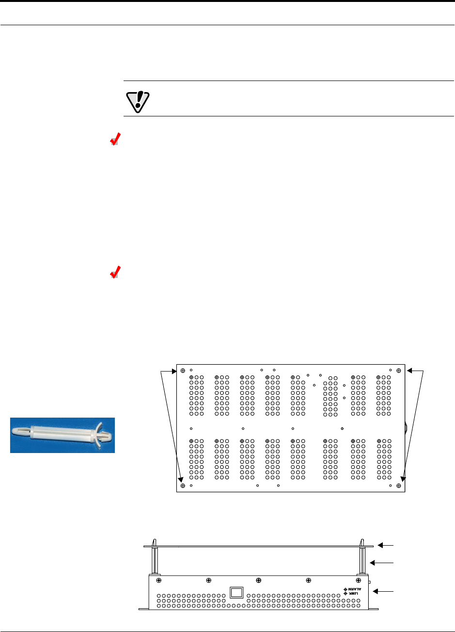
PN 8700-10 Help Hot Line (U.S. only): 1-800-530-9960 6-11
620003-0 Rev. A
PRELIMINARY Installing RAUs and Passive Antennas
6.4.1 Installing RAUs and Passive Antennas
CAUTION: Install RAUs in indoor locations only.
Installing RAUs
Mount all RAUs in the locations marked on the floor plans.
Considerations:
• Install iDEN and 800 MHz cellular RAUs so that their antennas will be at
least 6 to 8 meters (20 to 26 feet) apart.
• Keep at least 76 mm (3 in.) clearance around the RAU to ensure proper venting
• Always mount the RAU with the unpainted mounting face against the mounting
surface
Attaching the Optional RAU Dust Cover
Use the optional RAU dust cover when installing the RAU in an area where excessive
dust or debris could enter its venting holes.
To attach the optional RAU dust cover:
1. Firmly insert the four mounting pegs into the four corners on the top side of the
RAU, as shown in the following diagram.
2. Position the dust cover over the mounting pegs and press to snap into place.
The following diagram shows a side view of the dust cover attached to the RAU.
Insert
mountng
pegs
Insert
mountng
pegs
Insert this end
of mounting peg
into the RAU
Insert this end
of mounting peg
into the dust cover
Dust Cover
Mounting Peg
RAU

Installing Unison Components PRELIMINARY
6-12 InterReach Unison User Guide and Reference Manual PN 8700-10
620003-0 Rev. A
Installing Passive Antennas
Refer to the manufacturer’s installation instructions to install passive antennas.
Passive antennas are usually installed below the ceiling. If they are installed above
the ceiling, the additional loss due to the ceiling material must be considered when
estimating the antenna coverage area.
Considerations:
• Use coaxial cable with the least amount of loss possible.
• Keep iDEN and 800 MHz cellular antennas at least 6 to 8 meters (20 to 26 ft)
apart.
Connecting the Antenna to the RAU
Connect a passive antenna to the SMA male connector on the RAU using coaxial
cable.
CAUTION:When connecting to the SMA female connector on
the RAU and passive antenna, DO NOT over-tighten the connec-
tor. Firmly hand-tightening the connector is adequate.

PN 8700-10 Help Hot Line (U.S. only): 1-800-530-9960 6-13
620003-0 Rev. A
PRELIMINARY Installing RAUs and Passive Antennas
Testing and Connecting the ScTP Cable
Consideration:
• Before connecting the ScTP cable to the RAU, confirm that it meets TIA/EIA
568-A standard and the TIA/EIA/IS-729 supplement.
To test and connect the ScTP cable:
1. Perform cable testing.
Test results are required for the final As-Built Document.
Cable length:
– Absolute Minimum: 10 m (33 ft)
– Recommended Minimum: 25 m (82 ft)
– Recommended Maximum: 100 m (328 ft)
– Absolute Maximum: 150 m (492 ft)
2. Label the cable and make a note of the designation.
This information is needed when connecting the cable to the Expansion Hub.
3. Connect the cable to the RJ-45 female port on the RAU.
Power is supplied by the Expansion Hub. Because the Expansion Hub is not yet
connected, no LEDs will illuminate.
6.4.1.1 Installing RAUs in a Neutral Host System
When installing both iDEN and cellular systems in parallel, either as dual-band or
neutral host systems, special provision must be taken to assure that the individual
RAUs do not interfere with each other.
The 800 MHz cellular and iDEN RAU’s antennas must be separated by 6 to 8
meters (20 to 26 feet) to assure that the iDEN downlink signals do not interfere
with the cellular uplink signals.

Installing Unison Components PRELIMINARY
6-14 InterReach Unison User Guide and Reference Manual PN 8700-10
620003-0 Rev. A
6.4.2 Installing Expansion Hubs
The Expansion Hub (2U high) can mount in a standard 19 in. (483 mm) equipment
rack or in a wall-mountable equipment rack that is available from LGC Wireless.
Allow clearance of 76 mm (3 in.) front and rear and 51 mm (2 in.) sides for air circu-
lation.
Install the Expansion Hub in a horizontal position only.
CAUTION: Install Expansion Hubs in indoor locations only.
Installing an Expansion Hub in a Rack
Consideration:
• The Expansion Hub is shipped with #10-32 mounting screws. Another common
rack thread is #12-24. Confirm that the mounting screws match the rack’s threads.
• If you want to move the mounting brackets to a mid-mounting position, see Install-
ing an Expansion Hub in a Wall-Mounted Rack on page 6-15.
To install the hub in a rack:
1. Insert spring nuts into the rack where needed or use existing threaded holes.
2. Place the Expansion Hub into the rack from the front.
3. Align the flange holes with the spring nuts installed in Step 1.
4. Insert the mounting screws in the appropriate positions in the rack.
5. Tighten the mounting screws.
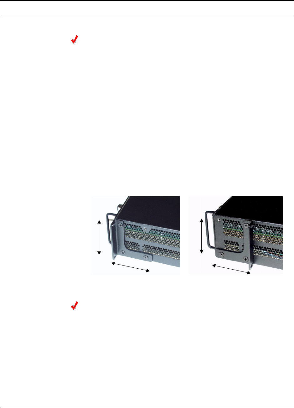
PN 8700-10 Help Hot Line (U.S. only): 1-800-530-9960 6-15
620003-0 Rev. A
PRELIMINARY Installing Expansion Hubs
Installing an Expansion Hub in a Wall-Mounted Rack
Considerations:
• The rack and the Expansion Hub are both 305 mm (12 in.) deep. The rack mount-
ing brackets on the Expansion Hub must be moved from the front position to allow
for the 76 mm (3 in.) rear clearance required.
• The maximum weight the rack can hold is 22.5 kg (50 lbs).
To install the hub in a wall-mounted rack:
1. Attach the equipment rack to the wall using the screws that are provided.
The rack must be positioned so that the Expansion Hub will be in a horizontal
position when it is installed.
2. Remove both of the rack mounting brackets from the hub.
3. Reattach each of the rack mounting brackets to the opposite side of the hub from
which it came.
Refer to the following figure for bracket placement.
4. Attach the Expansion Hub to the rack.
Installing an Optional Cable Manager in the Rack
• Using the screws provided, fasten the cable manager to the rack, immediately
above or below the Expansion Hub.
Right Rack Mounting Bracket as
installed from the factory.
Left Rack Mounting Bracket installed on
the right side of the hub.
3''
3.5''
3''
3.5''

Installing Unison Components PRELIMINARY
6-16 InterReach Unison User Guide and Reference Manual PN 8700-10
620003-0 Rev. A
Powering On the Expansion Hub
1. Connect the AC power cord to the Expansion Hub.
2. Plug the power cord into an AC power outlet.
3. Turn on the power to the Expansion Hub and check that all the LED lamps are
functioning properly.
Upon power-up, the LEDs will blink for five seconds for a visual check that they
are functioning. After the five-second test:
•The
POWER and UL STATUS LEDs should be green.
•The
E-HUB STATUS and DL STATUS LEDs should be red because the Main Hub
is not yet connected.
• All port LEDs should be off because no RAUs are connected yet.
NOTE: Leave the dust caps on the fiber ports until you are ready to connect the fiber
optic cables.
Testing and Connecting the Fiber Cables
Considerations:
• Before connecting the fiber cables, confirm that their optical loss does not exceed
3 dB optical budget.
• If fiber distribution panels are used, confirm that the total optical loss of fiber
cable, from the Main Hub through distribution panels and patch cords to the
Expansion Hub, does not exceed the optical budget.
• Make sure the fiber cable’s connectors are SC/APC (angle-polished).Using any
other connector type will result in degraded system performance and may damage
the equipment. (You can use an SC/APC pigtail if the fiber cable’s connectors are
not SC/APC, see “Splicing Fiber and Pigtail” on page 6-18.)
NOTE: Observe all Fiber Port Safety Precautions listed in Section 6.2.3 on page 6-4.
To test the fiber cables:
1. Perform cable testing and record the results.
Test results are required for the final As-Built Document.
2. Make a note of which cable you will use for uplink and downlink.
This information is needed when connecting the cables to the Main Hub.

PN 8700-10 Help Hot Line (U.S. only): 1-800-530-9960 6-17
620003-0 Rev. A
PRELIMINARY Installing Expansion Hubs
To clean the fiber ports:
Use compressed air to blow dust out of each fiber port before you insert the SC/APC
connector. Note that compressed air should not leave any residue as this will contam-
inate the fiber port.
To clean the fiber connectors:
Be sure that the fiber cable’s SC/APC connectors are clean and free of dust or oils. If
the fiber connector front face is not free of dust or oils, follow the manufacturer’s rec-
ommendations for cleaning it.
To connect the fiber cables:
The fiber cable is labeled with either 1 or 2, or is color-coded. In addition to these
labels, you should add a code that identifies which port on the Main Hub is being
used and which Expansion Hub the cables are intended for. This differentiates the
connectors for proper connection between the Main Hub and Expansion Hubs.
If the fiber jumper is labeled with 1 or 2:
1. Connect 1 to UPLINK on Expansion Hub.
2. Connect 2 to DOWNLINK on Expansion Hub.
3. Label both ends of each cable with which Main Hub port is used.
For example:
First pair to Main Hub port 1: 11 (uplink), 12 (downlink);
Second pair to Main Hub port 2: 21 (uplink), 22 (downlink);
Third pair to Main Hub port 3: 31 (uplink), 32 (downlink); and so on.
4. Record which number you connected to UPLINK and DOWNLINK.
This information is needed when connecting the other end of the fiber cable to the
Main Hub’s fiber ports.
If the fiber jumper is color-coded (for example, “blue” or “red”):
1. Connect “blue” to UPLINK on Expansion Hub.
2. Connect “red” to DOWNLINK on Expansion Hub.
3. Label both ends of each cable with which Main Hub port is used.
For example:
First pair to Main Hub port 1: 11 (uplink), 12 (downlink);
Second pair to Main Hub port 2: 21 (uplink), 22 (downlink);
Third pair to Main Hub port 3: 31 (uplink), 32 (downlink); and so on.
4. Record which color and port number you connected to UPLINK and DOWNLINK.
This information is needed when connecting the other end of the fiber cable to the
Main Hub’s fiber ports.

Installing Unison Components PRELIMINARY
6-18 InterReach Unison User Guide and Reference Manual PN 8700-10
620003-0 Rev. A
Splicing Fiber and Pigtail
The fiber cable must have SC/APC connectors. If it does not, you can splice a pigtail,
which has SC/APC connectors, to the fiber cable.
There are two different pigtails: 1 for single-mode fiber (PN 4013SCAPC-3) and 1
for multimode fiber (PN 4012SCAPC-3).
To splice the fiber optic cable to the SC/APC pigtail: Option A
1. Secure both the fiber cable and the SC/APC pigtail in a splice tray that is installed
immediately adjacent to the Hub.
2. Prepare the fiber end by ring-cutting the polyethylene jacket, cutting back the
Kevlar strands, and stripping back the fiber cladding.
Ensure that sufficient slack is maintained in order to be able to reach the fusion
splicer.
3. Clean the unclad fiber core using isopropyl alcohol and lint-free wipes.
4. Cleave the unclad fiber to the length prescribed by the fusion splicer’s specifica-
tion sheets.
5. Repeat steps 2 through 4 for the SC/APC pigtail.
6. Pass the splice sleeve onto the fiber strand.
7. Position both fiber ends in the fusion splicer and complete splice in accordance
with the fusion splicer’s operation instructions.
8. Ensure that the estimated loss for the splice as measured by the fusion splicer is
0.10 dB or better.
9. Slide the fusion splicing sleeve over the point of the fusion splice.
10. Place the sleeve and fused fiber into the fusion splicer’s heater.
11. Allow time for the splice sleeve to cure.
12. Return fiber splice to the splice tray, store the sleeve in a splice holder within the
tray, and store excess cable length in accordance with the tray manufacture’s
directions.
After successfully testing the fiber, plug the SC/APC pigtail into the proper opti-
cal port on the Hub.

PN 8700-10 Help Hot Line (U.S. only): 1-800-530-9960 6-19
620003-0 Rev. A
PRELIMINARY Installing Expansion Hubs
To splice the fiber optic cable to the SC/APC pigtail: Option B
1. Secure both the fiber cable and the SC/APC pigtail in a splice tray portion of a
fiber distribution panel.
2. Prepare the fiber end by ring-cutting the polyethylene jacket, cutting back the
Kevlar strands, and stripping back the fiber cladding.
Ensure that sufficient slack is maintained in order to be able to reach the fusion
splicer.
3. Clean the unclad fiber core using isopropyl alcohol and lint-free wipes.
4. Cleave the unclad fiber to the length prescribed by the fusion splicer’s specifica-
tion sheets.
5. Repeat steps 2 through 4 for the SC/APC pigtail.
6. Pass the splice sleeve onto the fiber strand.
7. Position both fiber ends in the fusion splicer and complete splice in accordance
with the fusion splicer’s operation instructions.
8. Ensure that the estimated loss for the splice as measured by the fusion splicer is
0.10 dB or better.
9. Slide the fusion splicing sleeve over the point of the fusion splice.
10. Place the sleeve and fused fiber into the fusion splicer’s heater.
11. Allow time for the splice sleeve to cure.
12. Return fiber splice to the splice tray, store the sleeve in a splice holder within the
tray, and store excess cable length in accordance with the tray manufacture’s
directions.
13. After successfully testing the fiber cable, plug the SC/APC pigtail into the back
side of the SC/APC bulkhead in the Fiber Distribution Panel.
Install a SC/APC patch cord between the front side of the SC/APC bulkhead and
the proper optical port on the Hub.

Installing Unison Components PRELIMINARY
6-20 InterReach Unison User Guide and Reference Manual PN 8700-10
620003-0 Rev. A
Connecting the ScTP Cables
Considerations:
• Confirm that the cables have been tested and the results recorded.
To connect the ScTP cables:
1. Connect the ScTP cables to any available RJ-45 port on the Expansion Hub.
2. Record which RAU you are connecting to which port.
This information is required for the As-Built Document.
3. Tie-off cables or use the optional cable manager to avoid damaging the connec-
tors because of cable strain.
Checking the RJ-45 Port LEDs
•The LINK LED should be green indicating that power is being supplied to the RAU.
•The
RAU LED should be red indicating that communication is established but a
band is not programmed.
• If the LINK LED is red and the RAU LED is off, then the RAUs are not commu-
nicating with the Expansion Hub.
• If the LEDs are off, the RAU is not drawing power.

PN 8700-10 Help Hot Line (U.S. only): 1-800-530-9960 6-21
620003-0 Rev. A
PRELIMINARY Installing Expansion Hubs
6.4.2.1 Troubleshooting Expansion Hub LEDs During Installation
• All Expansion Hub LINK and E-HUB/RAU LEDs with RAUs connected should indi-
cate Green/Red, which indicates that the RAU is powered on and communication
has been established.
• The Expansion Hub UL STATUS LED should be Green.
6.4.2.2 Installing Expansion Hubs in a Neutral Host System
Installing Expansion Hubs in a neutral host system is the same as described in
Section 6.4.2 on page 6-14.
If rack-mounting the Expansion Hubs, we recommend mounting all neutral host sys-
tem hubs in the same rack(s) or location, grouped by frequency or carrier. For exam-
ple, group the Expansion Hubs for the iDEN carrier(s) together, then the 800 MHz
cellular carrier(s), and so on.
Table 6-5 Troubleshooting Expansion Hub LEDs During Installation
During
Installation LED State Action Impact
Expansion Hub
power is On and
no RAUs are
connected
POWER Off Check AC power; check that the
Expansion Hub power-on switch
is on; replace the Expansion Hub.
Expansion Hub is not powering on.
LINK LEDs
on but
didn’t
blink
through
all states
Replace the Expansion Hub. Microcontroller not resetting properly;
flash memory corrupted.
E-HUB/RAU
UL STATUS Red Replace the Expansion Hub. The Expansion Hub laser is not opera-
tional; no uplink between the Expansion
Hub and Main Hub.
LINK Red Port unusable; replace the Expan-
sion Hub when possible.
Current sensor fault; do not use the port.
E-HUB/RAU Off
Connect RAU LINK Off Check the Cat-5/6 cable. Power is not getting to the RAU.
E-HUB/RAU Off
LINK Red Test the Cat-5/6 cable. If the cable
tests OK, try another port. If the
second port’s LEDs are Red/Off,
replace the RAU. If the second
RAU doesn’t work; replace the
Expansion Hub.
Power levels to RAU are not correct;
communications are not established.
If the second port works, flag the first
port as unusable; replace EH when possi-
ble.
E-HUB/RAU Off
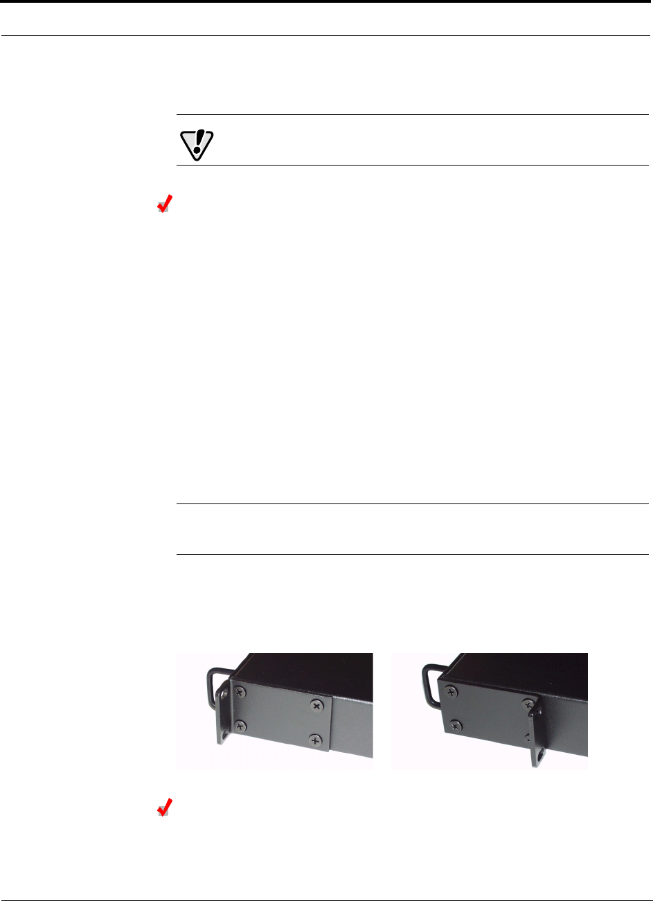
Installing Unison Components PRELIMINARY
6-22 InterReach Unison User Guide and Reference Manual PN 8700-10
620003-0 Rev. A
6.4.3 Installing a Main Hub
CAUTION: Install Main Hubs in indoor locations only.
Installing a Main Hub in a Rack
The Main Hub (1U high) mounts in a standard 19 in. (483 mm) equipment rack.
Allow clearance of 76 mm (3 in.) front and rear, and 51 mm (2 in.) on both sides for
air circulation.
Consideration:
• The Main Hub is shipped with #10-32 mounting screws. Another common rack
thread is #12-24. Confirm that the mounting screws match the rack’s threads.
To install the hub in a rack:
1. Insert spring nuts into rack where needed or use existing threaded holes.
2. Place the Main Hub into the rack from the front.
3. Align the flange holes with the spring nuts installed in Step 1.
4. Insert the mounting screws in the appropriate positions in the rack.
5. Tighten the mounting screws.
NOTE: Do not turn on the Main Hub until you’ve started the AdminMan-
ager software (see Section 6.5 on page 6-24).
Rack-mounting Option
You can flip the rack mounting brackets, as shown in the following figure, so the hub
can be mounted 76 mm (3 in.) forward in the rack.
Installing an Optional Cable Manager in the Rack
• Using the screws provided, fasten the cable manager to the rack, immediately
above or below the Main Hub.

PN 8700-10 Help Hot Line (U.S. only): 1-800-530-9960 6-23
620003-0 Rev. A
PRELIMINARY Installing Main Hubs in a Neutral Host System
6.4.4 Installing Main Hubs in a Neutral Host System
Installing Main Hubs in a neutral host system is the same as described in
Section 6.4.3 on page 6-22.
We recommend mounting all neutral host system Main Hubs in the same rack(s),
grouped by frequency or carrier. For example, group the Main Hubs for the iDEN
carrier(s) together, then the 800 MHz cellular carrier(s), and so on.
Connecting to base stations and repeaters is the same as described in Section 6.6 on
page 6-29 and Section 6.6.1 on page 6-33.

Installing Unison Components PRELIMINARY
6-24 InterReach Unison User Guide and Reference Manual PN 8700-10
620003-0 Rev. A
6.5 Starting and Configuring the System
Connecting a Laptop and Starting the AdminManager Software
Considerations:
• The AdminManager software is installed on a laptop computer that meets the
requirements that are listed on page 7-2.
• Null modem cable with female connectors is needed.
To connect the laptop and start the AdminManager software:
1. Connect the null modem cable to the laptop and then to the RS-232 port on the
Main Hub’s front panel.
2. Turn on the laptop and start the AdminManager software.
The main Installation Wizard window is displayed when the software is ready.
Powering On the Main Hub
After mounting the Main Hub in the rack, connect it to the AC power. You may use
multiple outlet surge protectors for multiple Main Hubs.
1. Connect the AC power cord to the Main Hub.
2. Plug the power cord into an AC power outlet.
3. Turn on the power.
Upon power-up, the LEDs will blink for five seconds for a visual check that they
are functioning. After the five-second test:
•The
POWER LED should be green.
•The
MAIN HUB STATUS LED should be red because a band has not been pro-
grammed.
• All fiber port LEDs should be off, indicating that no fiber cables are connected.
NOTE: Leave the dust caps on the fiber ports until you are ready to connect the fiber
optic cables.

PN 8700-10 Help Hot Line (U.S. only): 1-800-530-9960 6-25
620003-0 Rev. A
PRELIMINARY Starting and Configuring the System
Connecting the Fiber Cables to the Main Hub
Considerations:
• Before connecting the fiber cables, confirm that their optical loss does not exceed
3 dB optical budget.
• If fiber distribution panels are used, confirm that the total optical loss of fiber
cable, from the Main Hub through distribution panels and patch cords to the
Expansion Hub, does not exceed the optical budget.
• Make sure the fiber cable’s connectors are SC/APC (angle-polished). Using any
other connector type will result in degraded system performance and may damage
the equipment. (You can use an SC/APC pigtail if the fiber cable’s connectors are
not SC/APC, see “Splicing Fiber and Pigtail” on page 6-18.)
NOTE: Observe all Fiber Port Safety Precautions listed in Section 6.2.3 on page 6-4.
To clean the fiber ports:
Use compressed air to blow dust out of each fiber port before you insert the SC/APC
connector. Note that compressed air should not leave any residue as this will contam-
inate the fiber port.
To clean the fiber connectors:
Be sure that the fiber cable’s SC/APC connectors are clean and free of dust or oils. If
the fiber connector front face is not free of dust or oils, follow the manufacturer’s rec-
ommendations for cleaning it.
To connect the fiber cables:
The fiber cable is labeled with either 1 or 2, or is color-coded. For proper connection
between the Main Hub ports and the Expansion Hub ports, refer to the numbering or
color-coded connections you recorded when installing the Expansion Hub(s).
If the fiber jumper is labeled with 1 or 2:
1. Connect 1s to UPLINK ports on the Main Hub.
Refer to the connections you recorded, or the cable label, when the Expansion
Hub(s) were installed to know which Main Hub UPLINK port to use.
2. Connect 2s to DOWNLINK ports on the Main Hub.
Refer to the connections you recorded, or the cable label, when the Expansion
Hub(s) were installed to know which Main Hub DOWNLINK port to use.
If the fiber jumper is color-coded (for example, “blue” or “red”):
1. Connect “blue” to UPLINK ports on the Main Hub.
Refer to the connections you recorded, or the cable label, when the Expansion
Hub(s) were installed to know which Main Hub UPLINK port to use.
2. Connect “red” to DOWNLINK ports on the Main Hub.
Refer to the connections you recorded, or the cable label, when the Expansion
Hub(s) were installed to know which Main Hub DOWNLINK port to use.

Installing Unison Components PRELIMINARY
6-26 InterReach Unison User Guide and Reference Manual PN 8700-10
620003-0 Rev. A
Checking the Main Hub’s Fiber Port LEDs
•The LINK LED should be green if the fiber is connected to the Expansion Hub, and
communication and optical power are okay.
•The
E-HUB/RAU LED should be red because a band has not been programmed.
• If the LINK LED is red and the E-HUB/RAU LED is off, there is no communica-
tion with the Expansion Hub. Check the fiber cables (downlink first); a cable
may be broken or the optical link budget may be exceeded.
• If the PORT LEDs are blank (off), the Main Hub does not recognize the pres-
ence of an Expansion Hub. Check the fiber cables (uplink first); a cable may be
broken or the optical link budget may be exceeded. Check to ensure that the
cables are connected at the Expansion Hub, and that the Expansion Hub’s
power is on.
NOTE: Refer to Section 10 for troubleshooting.

PN 8700-10 Help Hot Line (U.S. only): 1-800-530-9960 6-27
620003-0 Rev. A
PRELIMINARY Troubleshooting Main Hub LEDs During Installation
6.5.1 Troubleshooting Main Hub LEDs During Installation
The following Main Hub LED indications assume that the Expansion Hub LEDs have
already been checked.
• All Main Hub fiber port LEDs that have Expansion Hubs connected to them
should be Green/Red, indicating that the Expansion Hub is powered on and com-
munication has been established.
Table 6-6 Troubleshooting Main Hub LEDs During Installation Power On
During
Installation
Power On LED State Action Impact
Main Hub
power is On
with no
Expansion
Hubs con-
nected.
POWER Off Check AC power; check that the
Main Hub power-on switch is on;
replace Main Hub
Main Hub is not powering on.
LINK LEDs on
but didn’t
blink
through all
states
Replace the Main Hub. Microcontroller not resetting properly;
flash memory corrupted.
E-HUB/RAU
LINK Red The port is unusable; replace the
Main Hub when possible.
Fiber sensor fault, do not use the port.
E-HUB/RAU Off
Connect
Expansion
Hub Fiber
Pair
LINK Off Swap the uplink and downlink
cables. If the port LEDs do not illu-
minate, check the fiber uplink for
excessive optical loss.
Connect the fiber pair to another port.
If the second port’s LEDs do not illu-
minate Green/Red, replace the Main
Hub.
The Main Hub does not sense the
presence of the Expansion Hub.
If the second port works, flag the first
port as unusable; replace the Main
Hub when possible.
E-HUB/RAU Off
LINK Red If the Expansion Hub DL STATUS
LED is red, check the downlink fiber
cable for excessive optical loss.
Connect the fiber pair to another port.
If the second port’s LEDs do not illu-
minate Green/Red, replace the Main
Hub.
The Expansion Hub does not sense the
presence of the Main Hub.
If the second port works, flag the first
port as unusable; replace the Main
Hub when possible.
E-HUB/RAU Off

Installing Unison Components PRELIMINARY
6-28 InterReach Unison User Guide and Reference Manual PN 8700-10
620003-0 Rev. A
Configuring the Unison System
The system will not work until a band has been set and a system test is performed.
• The AdminManager software must be running on a PC/laptop that is connected to
the Main Hub’s front panel RS-232 connector.
1. Select the Installation Wizard (Local) mode radio button and click RUN.
The Step 1, Verify Hardware window is displayed.
Refer to Section 7.2 on page 7-13 for a description of the Installation wizard.
2. Confirm that all system devices are displayed in the System Status box and click
NEXT.
The Step 2, Set Operation Band window is displayed.
3. Select the desired frequency band and click APPLY.
4. Click NEXT if the message displayed indicates a successful band setting.
The Step 3, Configure System Parameters window is displayed.
5. Enter the desired parameters and click APPLY.
6. Click NEXT if the message displayed indicates a successful parameter setting.
The Step 4, Final System Test window is displayed.
7. Click APPLY to initiate the final system test.
During testing the system is off-line and a center band tone is being transmitted.
8. Click NEXT if the message displayed indicates a successful test.
The Finish window is displayed.
9. Click FINISH.
The AdminManager session is ended and the window is closed.
NOTE: Refer to Section 10 for troubleshooting.
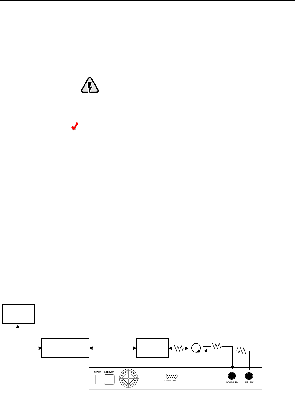
PN 8700-10 Help Hot Line (U.S. only): 1-800-530-9960 6-29
620003-0 Rev. A
PRELIMINARY Interfacing a Main Hub to a Base Station or Roof-top Antenna
6.6 Interfacing a Main Hub to a Base Station or
Roof-top Antenna
WARNING: Exceeding the maximum input power could cause failure
of the Main Hub (refer to Section 8.1 on page 8-3 for maximum power
specifications). If the maximum composite power is too high, attenua-
tion is required.
Connecting a Main Hub to a Roof-top Antenna
It is recommended that you use a lightning arrestor or surge protector in a roof-top
antenna configuration. Insert the lightning arrestor or surge protector between the
roof-top antenna and the repeater that is connected to the Main Hub.
1. Connect an N-male to N-male coaxial cable to the roof-top antenna.
2. Connect the other end of the N-male to N-male coaxial cable to the grounded
surge suppressor.
3. Connect an N-male to N-male coaxial cable to the grounded surge suppressor.
4. Connect the other end of the N-male to N-male coaxial cable to the repeater.
5. Connect an N-male to N-male coaxial cable to the repeater.
6. Connect the other end of the N-male to N-male coaxial cable to the circulator
1connector.
7. Connect an N-male to N-male coaxial cable to the circulator 2connector.
8. Connect the other end of the N-male to N-male coaxial cable to the DOWNLINK
connector on the Main Hub.
Attenuation may be required to achieve the desired RF output at the RAU.
9. Connect an N-male to N-male coaxial cable to the circulator 3connector.
10. Connect the other end of the N-male to N-male coaxial cable to the UPLINK con-
nector on the Main Hub.
Roof-top
Antenna
Grounded
Surge Suppressor Repeater
N-male to N-male
Coaxial Cables
N-male to N-male
Coaxial Cable
N-male to N-male
Coaxial Cable Circulator Attenuator (optional)
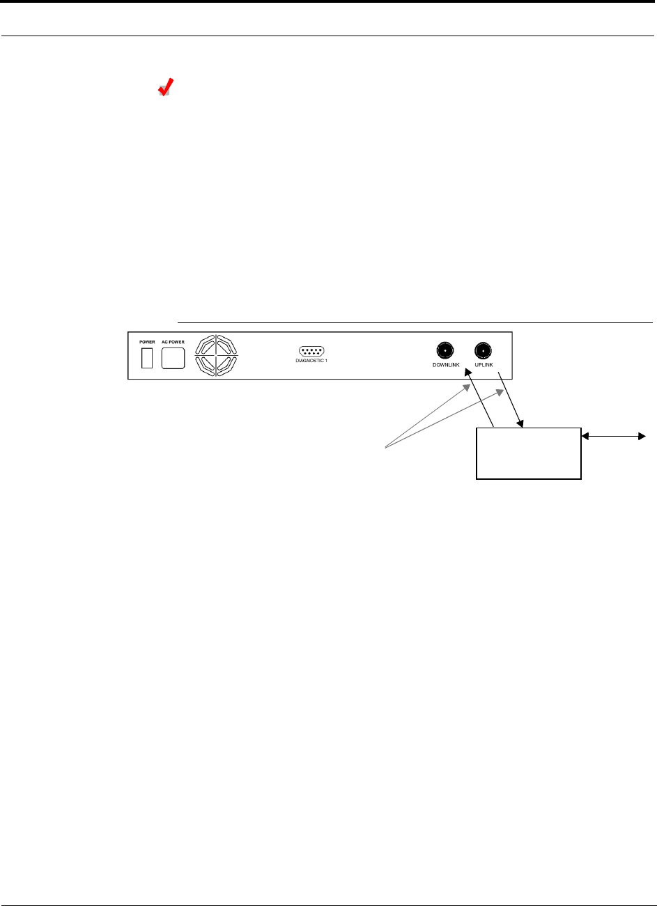
Installing Unison Components PRELIMINARY
6-30 InterReach Unison User Guide and Reference Manual PN 8700-10
620003-0 Rev. A
Connecting a Main Hub to an In-Building Base Station
Connecting a Simplex Base Station to a Main Hub:
1. Connect an N-male to N-male coaxial cable to the transmit simplex connector on
the base station.
2. Connect the other end of the N-male to N-male coaxial cable to the DOWNLINK
connector on the Main Hub.
3. Connect an N-male to N-male coaxial cable to the receive simplex connector on
the base station.
4. Connect the other end of the N-male to N-male coaxial cable to the UPLINK con-
nector on the Main Hub.
Figure 6-1 Simplex Base Station to a Main Hub
N-male to N-male
Coaxial Cable
Base Station
Simplex T1/E1 to
Mobile
Switching
Center
Insert attenuator, if needed
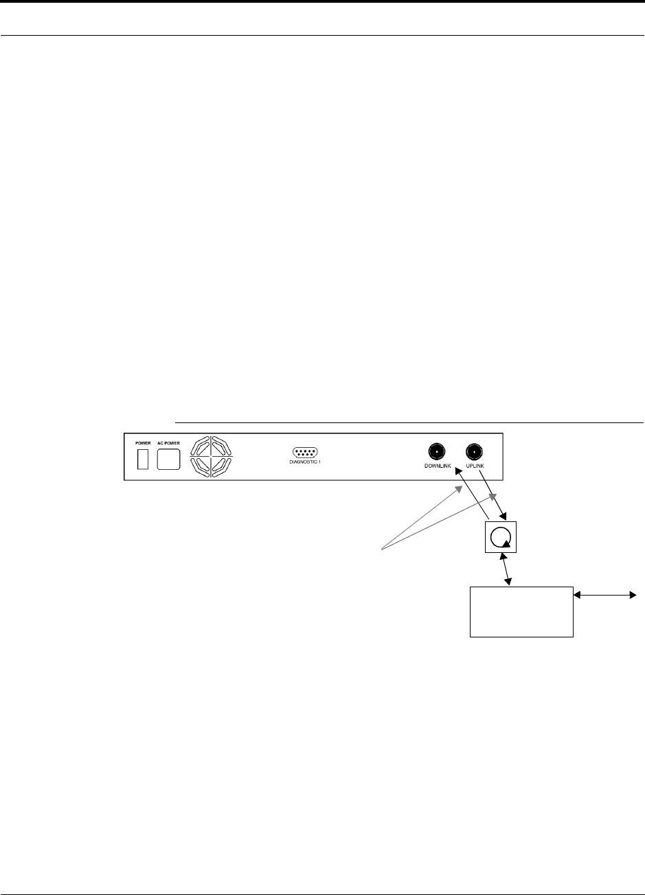
PN 8700-10 Help Hot Line (U.S. only): 1-800-530-9960 6-31
620003-0 Rev. A
PRELIMINARY Interfacing a Main Hub to a Base Station or Roof-top Antenna
Connecting a Duplex Base Station to a Main Hub:
When connecting to a duplex base station, use a circulator between it and the Main
Hub.
You can insert attenuators between the circulator and Main Hub as needed; refer to
Section 8.6.1 on page 8-47 for more information.
1. Connect an N-male to N-male coaxial cable to the duplex connector on the base
station.
2. Connect the other N-male connector to a circulator.
3. Connect an N-male to N-male coaxial cable to the DOWNLINK connector on the
Main Hub.
4. Connect the other end of the N-male coaxial cable to the transmit connector on the
circulator.
5. Connect an N-male to N-male coaxial cable to the UPLINK connector on the Main
Hub.
6. Connect the other end of the N-male coaxial cable to the receive connector on the
circulator.
Figure 6-2 Duplex Base Station to a Main Hub
N-male to N-male
Coaxial Cable
Base Station
Duplex T1/E1 to
Mobile
Switching
Center
Insert attenuator, if needed N-male to N-male
Coaxial Cable
Circulator
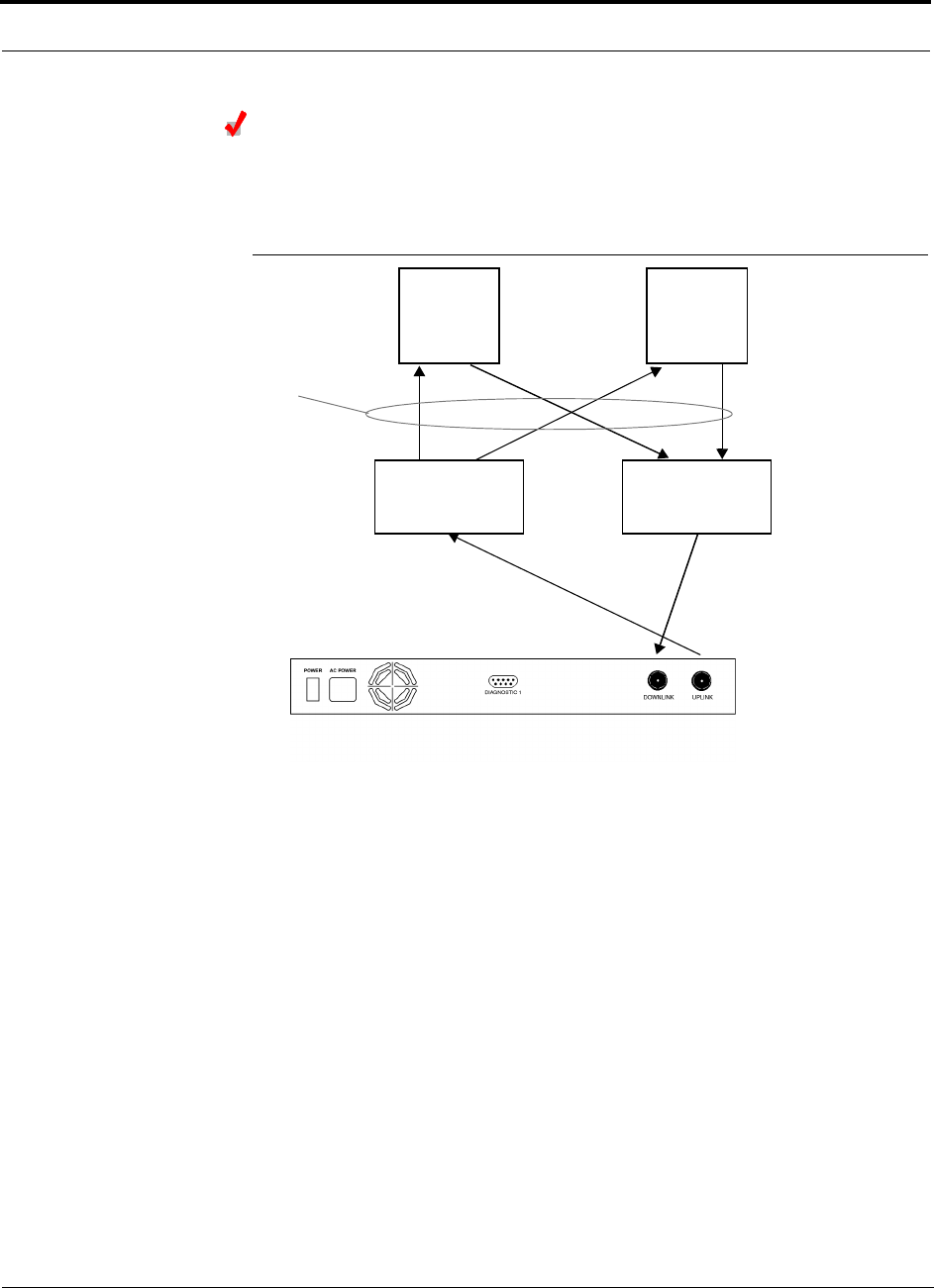
Installing Unison Components PRELIMINARY
6-32 InterReach Unison User Guide and Reference Manual PN 8700-10
620003-0 Rev. A
Connecting a Main Hub to Multiple Base Stations
You can use power combiner/splitters to connect a Main Hub to multiple base sta-
tions, as shown in the following figure.
Figure 6-3 Connecting a Main Hub to Multiple Base Stations
N-male to N-male
Coaxial Jumper Cables
N-male to N-male
Coaxial Jumper Cable
to Repeater or
Base Station
between Combiner/Splitter and
N-male to N-male
Coaxial Jumper Cables
between Combiner/Splitter and
Main Hub’s Uplink Port Main Hub’s Downlink Port
2 x 1 Power
Combiner/Splitter 2 x 1 Power
Combiner/Splitter
BTS 1
UL DL
BTS 2
UL DL
Insert attenuators, if needed
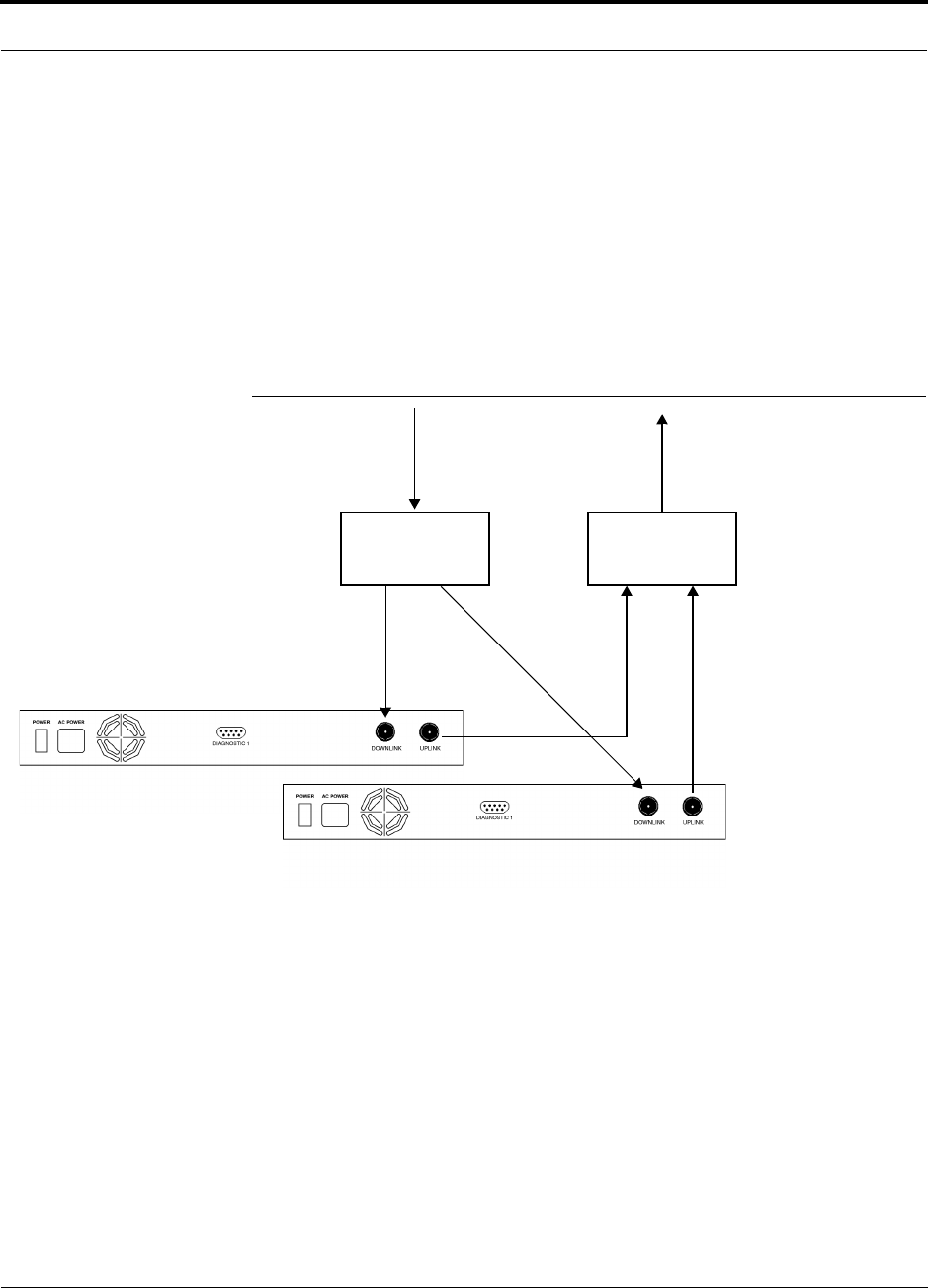
PN 8700-10 Help Hot Line (U.S. only): 1-800-530-9960 6-33
620003-0 Rev. A
PRELIMINARY Connecting Multiple Main Hubs
6.6.1 Connecting Multiple Main Hubs
You can use power combiner/splitters as splitters to connect multiple Main Hubs in
order to increase the total number of RAUs in a system. You can also use power com-
biner/splitters to combine base station channels in order to increase the number of RF
carriers the system transports.
The following figure shows connecting two Main Hubs to a simplex repeater or base
station. Connecting two Main Hubs increases the total number of supportable RAUs
from 32 to 64. Two Main Hubs support up to 8 Expansion Hubs which in turn support
up to 64 RAUs.
Figure 6-4 Connecting Two Main Hubs to a Simplex Repeater or Base Station
N-male to N-male
Coaxial Jumper Cables
N-male to N-male
Coaxial Jumper Cable
to Repeater or
Base Station
2 x 1 Power
Combiner/Splitter
N-male to N-male
Coaxial Jumper Cable
to Repeater or
Base Station
between Combiner/Splitter and N-male to N-male
Coaxial Jumper Cables
between Combiner/Splitter and
Main Hub’s Downlink Port
Main Hub’s Uplink Port
2 x 1 Power
Combiner/Splitter
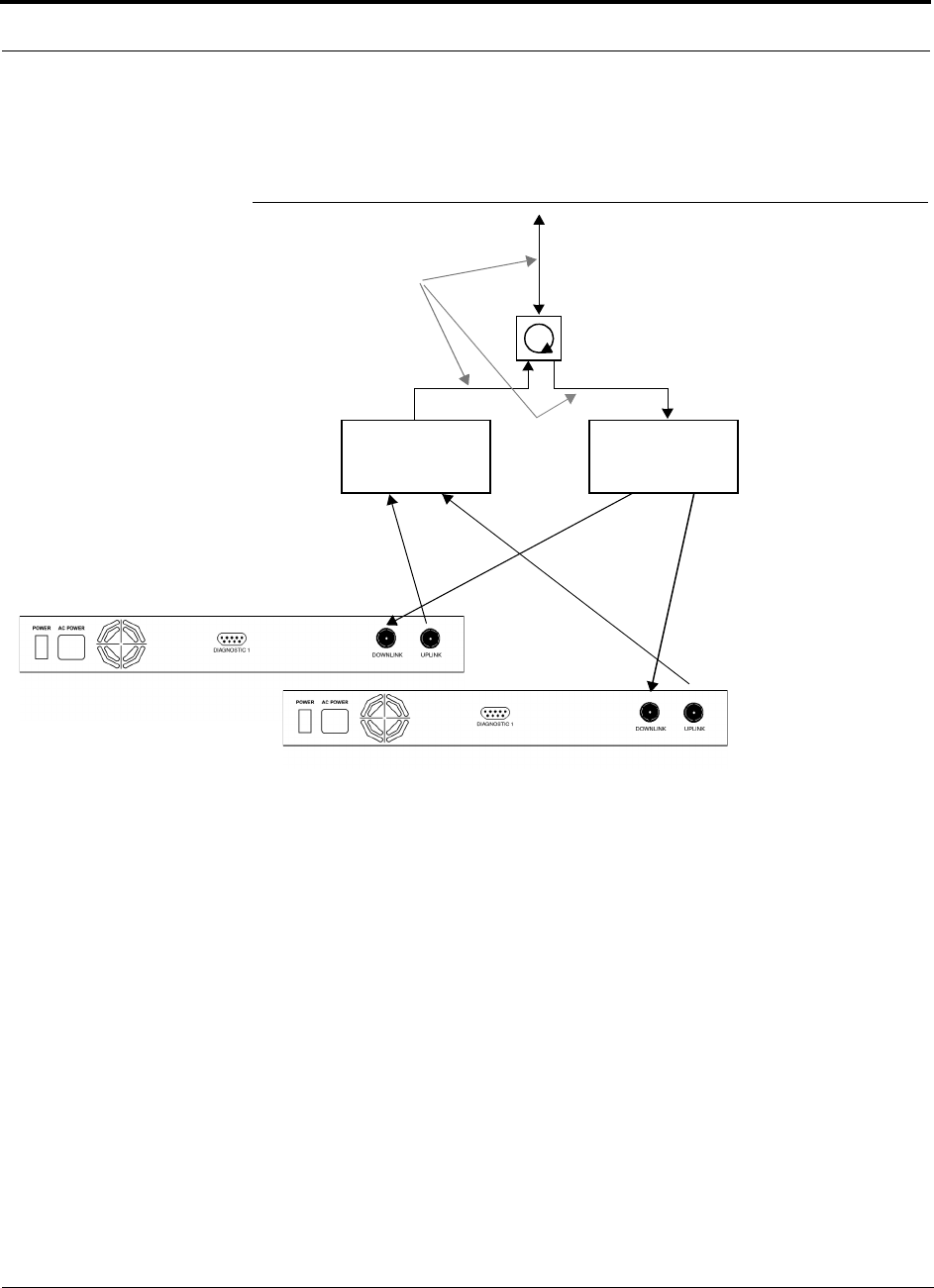
Installing Unison Components PRELIMINARY
6-34 InterReach Unison User Guide and Reference Manual PN 8700-10
620003-0 Rev. A
To connect two Main Hubs to a duplex repeater or base station, you need to use one
circulator and one more coaxial jumper cable, as shown in the following figure.
Figure 6-5 Connecting Two Main Hubs to a Duplex Repeater or Base Station
2 x 1 Power
Combiner/Splitter
N-male to N-male
Coaxial Jumper Cable
N-male to N-male
Coaxial Jumper Cables
2 x 1 Power
Combiner/Splitter
N-male to N-male
Coaxial Jumper Cable
Circulator
N-male to N-male
Coaxial Jumper Cable
to Repeater or
Base Station
between Combiner/Splitter and N-male to N-male
Coaxial Jumper Cables
between Combiner/Splitter and
Main Hub’s Downlink Port
Main Hub’s Uplink Port
Insert attenuator, if needed

PN 8700-10 Help Hot Line (U.S. only): 1-800-530-9960 6-35
620003-0 Rev. A
PRELIMINARY Connecting Multiple Main Hubs
Connecting Multiple Main Hubs to a Simplex Repeater
or Base Station
You will need the following:
• 2 hybrid power combiner/splitters; one for uplink and one for downlink (2x1 for
two Main Hubs, 3x1 for three, 4x1 for four, etc.)
• 1 N-male to N-male coaxial jumper cable between each power combiner/splitter
and the base station
• 2 N-male to N-male coaxial jumper cables between each power combiner/splitter
and each Main Hub
Figure 6-4 on page 6-33 illustrates this procedure.
1. Connect the power combiner/splitters to the repeater or base station using N-male
to N-male coaxial jumper cables:
a. From the first power combiner/splitter to the repeater or base station
b. From the second power combiner/splitter to the repeater or base station
2. Connect the power combiner/splitters to the Main Hubs:
a. From the first Main Hub’s UPLINK port to the first power combiner/splitter
b. From the first Main Hub’s DOWNLINK port to the second power com-
biner/splitter
c. From the second Main Hub’s UPLINK port to the first power combiner/splitter
d. From the second Main Hub’s DOWNLINK port to the second power com-
biner/splitter
3. Check Main Hub LEDs.
After connecting and powering on the Main Hub, check all LEDs to ensure that
the system is operating properly.
NOTE: Use a 50 ohm terminator on any unused power combiner/splitter ports.

Installing Unison Components PRELIMINARY
6-36 InterReach Unison User Guide and Reference Manual PN 8700-10
620003-0 Rev. A
Connecting Multiple Main Hubs to a Duplex Repeater
or Base Station
You will need the following:
• 2 hybrid power combiner/splitters; one for uplink and one for downlink (2x1 for
two Main Hubs, 3x1 for three, 4x1 for four, etc.)
• 2 N-male to N-male coaxial jumper cables to connect each Main Hub to the power
combiner/splitters
• 1 circulator
• 1 N-male to N-male coaxial jumper cable between each circulator and the repeater
or base station
• 1 N-male to N-male coaxial jumper cable1 between each circulator and power
combiner/splitter
Figure 6-5 on page 6-34 illustrates this procedure.
1. Connect the Circulator to the power combiner/splitters and to the repeater or base
station using one N-male to N-male coaxial jumper cable.
2. Connect each power combiner/splitter to the circulator using one N-male to
N-male coaxial jumper cable.
3. Connect the power combiner/splitter to the Main Hubs:
a. From the first Main Hub’s UPLINK port to the first power combiner/splitter
b. From the first Main Hub’s DOWNLINK port to the second power com-
biner/splitter
c. From the second Main Hub’s UPLINK port to the first power combiner/splitter
d. From the second Main Hub’s DOWNLINK port to the second power com-
biner/splitter
4. Check Main Hub LEDs.
After connecting and powering on the Main Hub, check all LEDs to ensure that
the system is operating properly.
NOTE: Use a 50 ohm terminator on any unused power combiner/splitter ports.

PN 8700-10 Help Hot Line (U.S. only): 1-800-530-9960 6-37
620003-0 Rev. A
PRELIMINARY Connecting Contact Alarms to a Unison System
6.7 Connecting Contact Alarms to a Unison System
The Unison Main Hub can generate (source) two contact alarms as well as sense an
external contact alarm.
• Alarm Source
The Main Hub has two alarm contacts, major and minor errors. These contacts are
normally-closed (NC) and will open when an internal alarm is detected.
• Major error is active when any faults or disconnects are detected.
• Minor error is active during a lockout or warning, or when the end-to-end sys-
tem test is not valid.
•Alarm Sense
The Main Hub can monitor an external alarm contact using this feature. The port
can be configured for normally-open (NO) or normally-closed (NC) contacts. The
interface expects a set of floating contacts. An external voltage source is not
required for this interface. AdminManager or OpsConsole is used to monitor the
port status.
The following table lists the alarm types, equipment that Unison is connected to,
cable(s) used, and the errors (major and/or minor) that are detected.
Note that only major errors are supported on MetroReach and LGCell, and that the
5-port Daisy-Chain Alarm Cable supports only major errors as well. Therefore, using
the 5-port Daisy-Chain Alarm Cable with equipment that supports both major and
minor errors will result in only major errors being detected. This is also the case when
using the Alarm Source Daisy-Chain Cable, which supports both major and minor
alarms, with MetroReach or LGCell because these systems only support major errors.
Alarm
Type Unison
connected to Cable(s) Used Errors Detected
Source MetroReach 5-port Daisy-Chain Alarm Cable
and male-to-male adapter cable that
is provided with MetroReach
Major
Alarm Source Daisy-Chain Cable Major
Source BTS 5-port Daisy-Chain Alarm Cable Major
Alarm Source Daisy-Chain Cable Major and Minor
Source ARM2000 Alarm Source Daisy-Chain Cable Major and Minor
Sense LGCell 5-port Daisy-Chain Alarm Cable
and the Alarm Sense Adapter Cable
Major
Alarm Source Daisy-Chain Cable
and the Alarm Sense Adapter Cable
Major
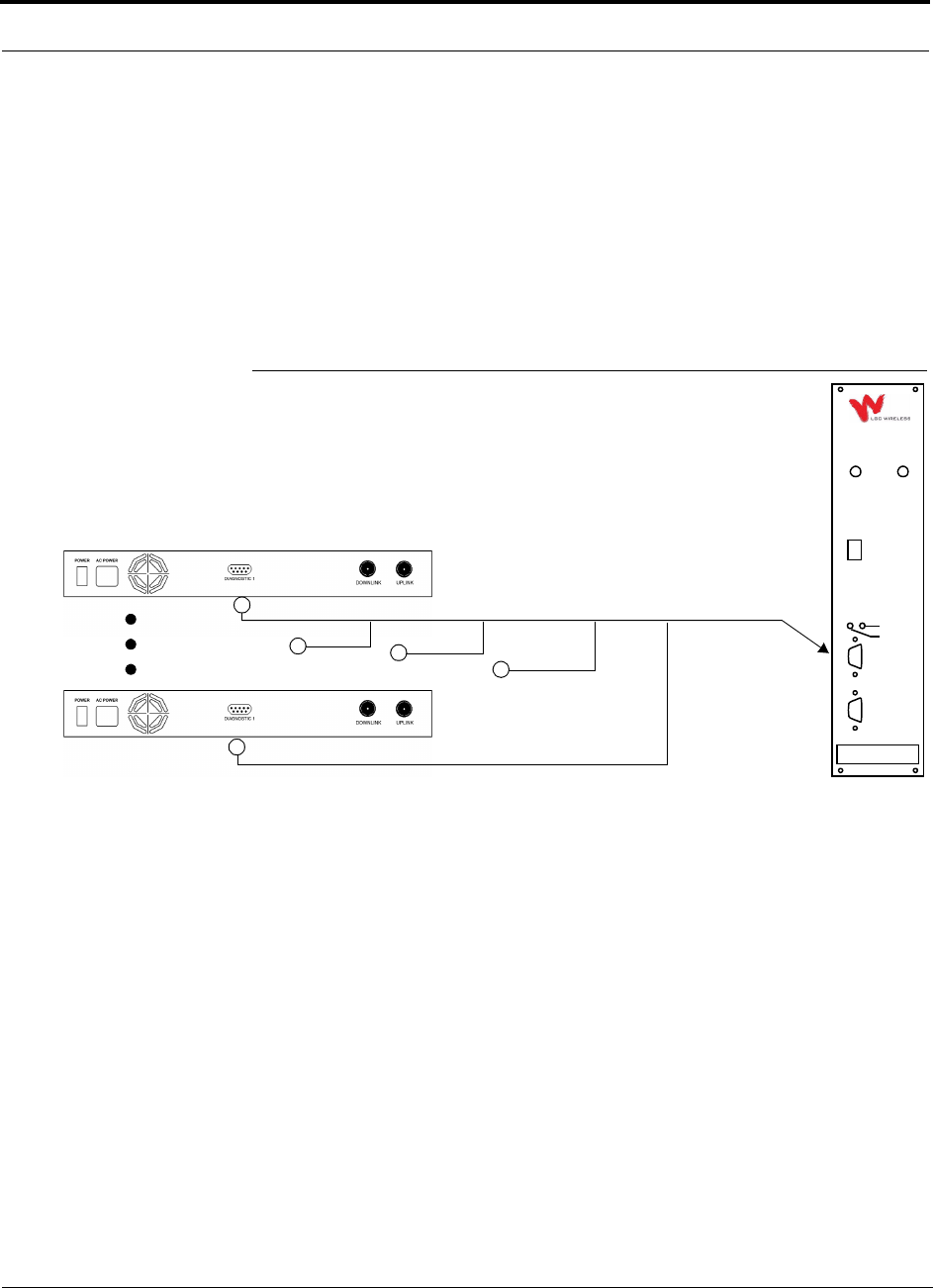
Installing Unison Components PRELIMINARY
6-38 InterReach Unison User Guide and Reference Manual PN 8700-10
620003-0 Rev. A
6.7.1 Alarm Source
Unison is always an alarm source, no matter what type of equipment you are connect-
ing to.
Using MetroReach Focus to Monitor Unison
When you connect MetroReach Focus to Unison, the Unison Main Hub is the output
of the alarms (alarm source) and Focus is the input (alarm sense), as shown in the fol-
lowing figure.
Figure 6-6 Connecting MetroReach to Unison
Focus supports only major errors. However, you can use either the 5-port
Daisy-Chain Alarm Cable (see page 6-41) or the Alarm Source Daisy-Chain Cable
(see page 6-42).
Unison Main Hub
RF OUT
DOWNLINK RF IN
UPLINK
FIBER
UPLINK
DOWNLINK
ALARM
RS-232C
MetroReach
Focus
RFM
Alarm
Sense
Alarm
Source
Alarm
Source
5-port Daisy-Chain Alarm Cable or Alarm Source Daisy-Chain Cable
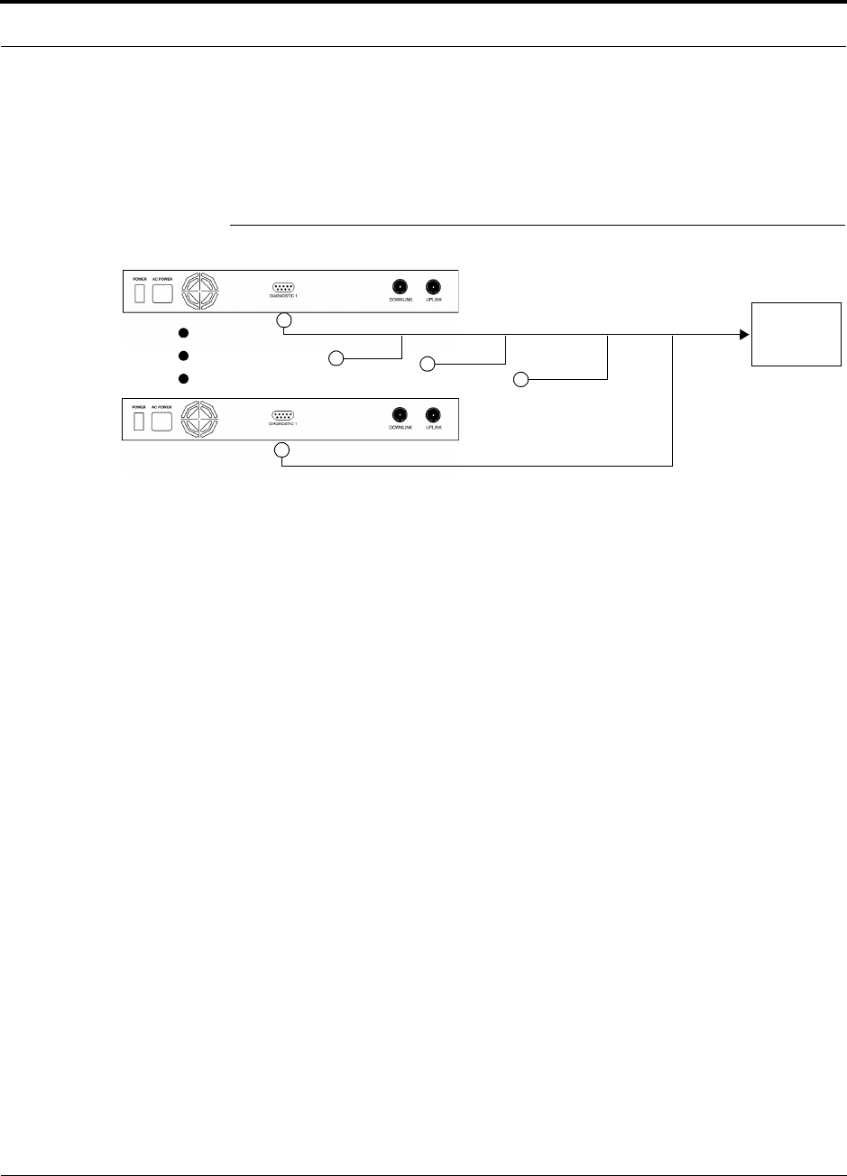
PN 8700-10 Help Hot Line (U.S. only): 1-800-530-9960 6-39
620003-0 Rev. A
PRELIMINARY Alarm Source
Using a Base Station to Monitor Unison
When you connect a BTS to Unison, the Unison Main Hub is the output of the alarms
(alarm source) and the BTS is the input (alarm sense), as shown in the following figure.
Figure 6-7 Connecting a BTS to Unison
Use the Alarm Source Daisy-Chain Cable (see page 6-42) to support both major and
minor errors or the 5-port Daisy-Chain Alarm Cable (see page 6-41) to support major
errors only.
Unison Main Hub
Alarm
Sense
Alarm
Source
Alarm
Source
BTS
5-port Daisy-Chain Alarm Cable or Alarm Source Daisy-Chain Cable
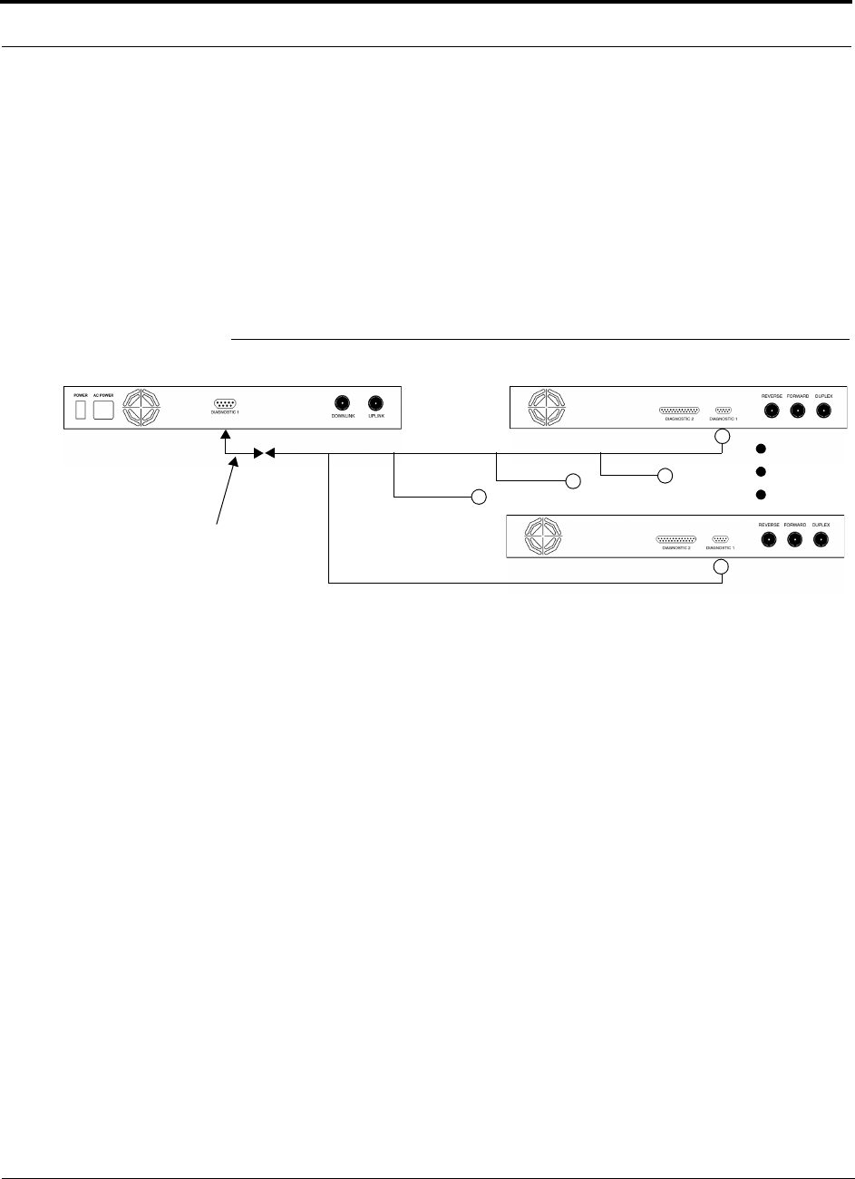
Installing Unison Components PRELIMINARY
6-40 InterReach Unison User Guide and Reference Manual PN 8700-10
620003-0 Rev. A
6.7.2 Alarm Sense
Use the AdminManager to enable the Unison system for “alarm sense” when con-
necting to the contact closure of LGCell Main Hubs or other external alarms.
Using Unison to Monitor LGCells
When you connect LGCell to Unison, the Unison Main Hub is the input of the alarms
(alarm sense) and the LGCell is the output (alarm source), as shown in the following
figure.
Figure 6-8 Connecting LGCell to Unison
LGCell supports only major errors. However, you can use either the 5-port
Daisy-Chain Alarm Cable (see page 6-41) or the Alarm Source Daisy-Chain Cable
(see page 6-42) . You must use the Alarm Sense Adapter Cable (see page 6-43) to
interface either cable to LGCell. The adapter cable is required to translate the LGCell
major error pinout to the sense input pins on the Unison Main Hub.
Up to 5 LGCell Main HubsUnison Main Hub
Alarm
Sense Alarm
Source
Alarm
Source
Alarm Sense
Adapter Cable
5-port Daisy-Chain Alarm Cable or Alarm Source Daisy-Chain Cable
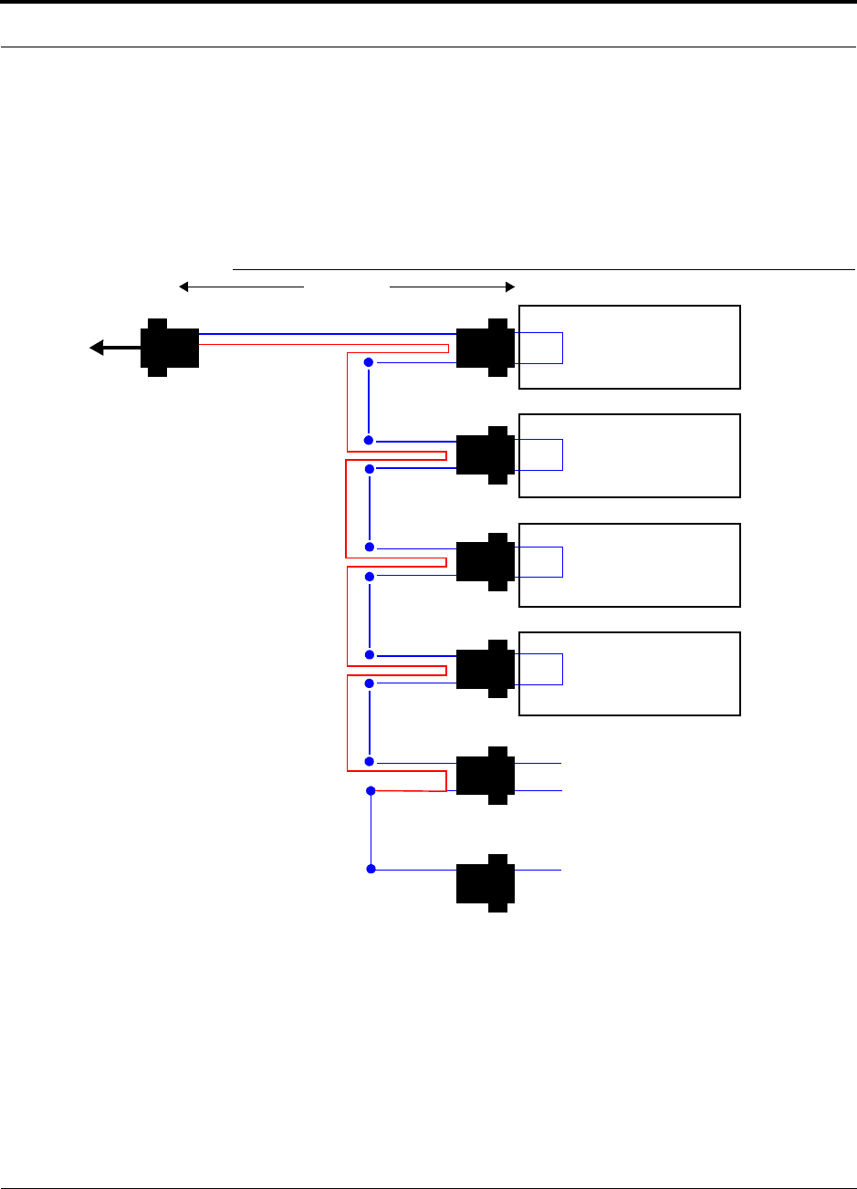
PN 8700-10 Help Hot Line (U.S. only): 1-800-530-9960 6-41
620003-0 Rev. A
PRELIMINARY Alarm Cables
6.7.3 Alarm Cables
5-port Daisy-Chain Alarm Cable
The 5-port Daisy-Chain Alarm Cable (PN 4022-5) supports only major errors. It is
shown in Figure 6-9.
Figure 6-9 5-port Daisy-Chained Alarm Cable
1 meter (3 feet)
Pins 7 and 9
J2
LGCell or MetroReach
Focus Alarm
DB-9 female Port
Pin 7
Pin 9 X
J3
Pin 7
Pin 9 X
J4
Pin 7
Pin 9 X
J5
Pin 7
Pin 9 X
J6J7
DB-9 male
Pins 7 and 9
DB-9 male
Pins 7 and 9
DB-9 male
Pins 7 and 9
DB-9 male
Pins 7 and 9
DB-9 male
Pin 7
DB-9 female
J1
DB-9 male 7
9
Pin 7
Pin 7
Option 1: Connect 5 units to cable using
J2 through J6; J7 is unused.
OR
Option 2: Connect four units to first cable
using J2 through J5, connect J6 to an
additional 300117-0 cable’s J1 connector;
J7 is unused.
OR
Option 3: Connect less than four units to
cable and terminate the circuit by con-
necting the J7 connector into the lowest
numbered unused male connector.
Pin 9
LGCell or MetroReach
Focus Alarm
DB-9 female Port
LGCell or MetroReach
Focus Alarm
DB-9 female Port
LGCell or MetroReach
Focus Alarm
DB-9 female Port
to Unison,
Base Station,
MetroReach
Focus (use the
male-to-male adapter
that is included with
the cable), or to the
Alarm Sense Adapter
Cable when connecting
to LGCell.
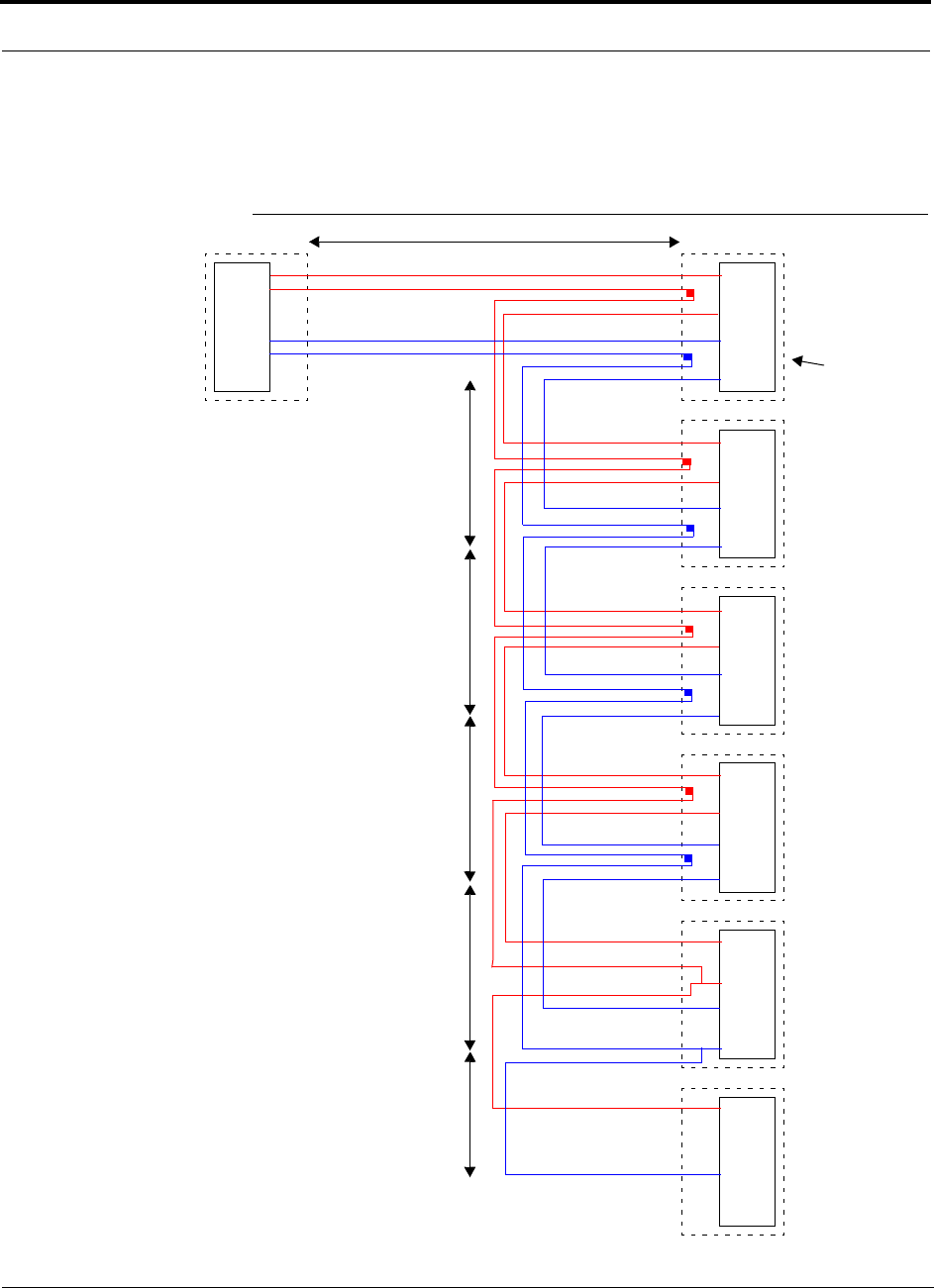
Installing Unison Components PRELIMINARY
6-42 InterReach Unison User Guide and Reference Manual PN 8700-10
620003-0 Rev. A
Alarm Source Daisy-Chain Cable
The Alarm Source Daisy-Chain Cable (PN 4024-3) is shown in Figure 6-10.
Figure 6-10 Alarm Source Daisy-Chain Cable
DB-9 female to
Base Station
MetroReach Focus,
ARM2000-RU, or
J1
Female J2
Male
J3
Male
J4
Male
J5
Male
J6
Male
J7
Female
Terminator
Splice
Splice
Splice
Splice
Splice
Splice
Splice
Splice
7
9
4
5
7
9
4
5
7
9
4
5
7
9
4
5
7
9
4
5
7
4
1.2 meters (4 feet)
.5 meter
(1.5 feet)
DB-9 male to
Unison, MetroReach
Focus, or LGCell
Alarm Port
DB-9 male to
Unison, MetroReach
Focus, or LGCell
Alarm Port
DB-9 male to
Unison, MetroReach
Focus, or LGCell
Alarm Port
DB-9 male to
Unison, MetroReach
Focus, or LGCell
Alarm Port
Option 1: DB-9 to
Unison, MetroReach
Focus, or LGCell
Alarm Port.
J7 not used
Option 2: Use J2-J5
for alarm ports. J6 is used
to connect to an additional
Alarm Daisy-Chain Cable.
J7 is not used.
Option 3: Connect
fewer than 5 ports and
terminate the daisy chain
by connecting J7 to the
lowest unused port.
Connector
Hood
.5 meter
(1.5 feet)
.5 meter
(1.5 feet)
.5 meter
(1.5 feet)
.25 meter
(.75 feet)
the Alarm Sense
Adapter Cable when
connecting to LGCell
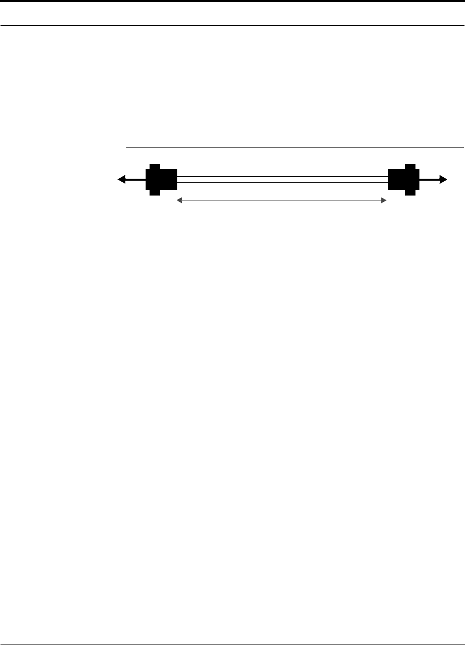
PN 8700-10 Help Hot Line (U.S. only): 1-800-530-9960 6-43
620003-0 Rev. A
PRELIMINARY Alarm Cables
Alarm Sense Adapter Cable
The alarm sense adapter cable (PN 4025-1) translates the LGCell major error pinout
to the sense input pins on the Unison Main Hub. You must use this adapter cable, as
illustrated in Figure 6-11, with the 5-port Daisy-Chain Alarm Cable or the Alarm
Source Daisy-Chain Cable when connecting LGCell to Unison.
Figure 6-11 Alarm Sense Adapter Cable
J8
1
8
J9
7
9
To Unison To Daisy-Chain Cable
3 feet

Installing Unison Components PRELIMINARY
6-44 InterReach Unison User Guide and Reference Manual PN 8700-10
620003-0 Rev. A