ADC Telecommunications UNS-IDEN-1 InterReach Unison IDEN User Manual unison
ADC Telecommunications Inc. InterReach Unison IDEN unison
UserManual.wiki
>
ADC Telecommunications
>
UNS-IDEN-1 User Manual
>
User Manual 2
Contents
1.
User Manual 1
2.
User Manual 2
3.
Users Manual
User Manual 2
Navigation menu
Upload a User Manual
Namespaces
Wiki Guide
HTML
PDF
Info
Views
User Manual
Discussion / Help
Navigation
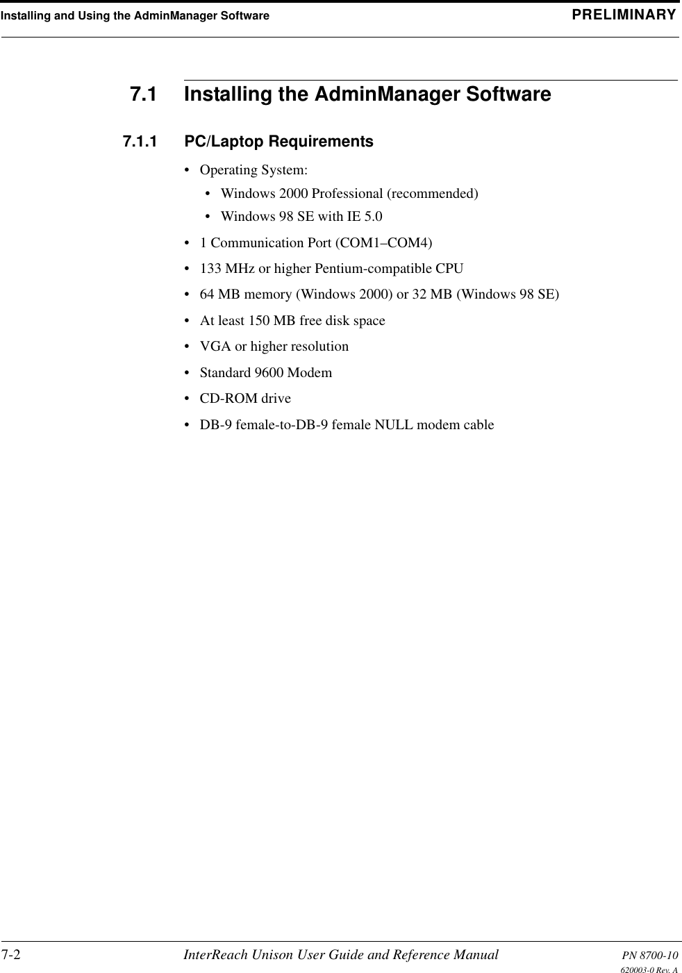

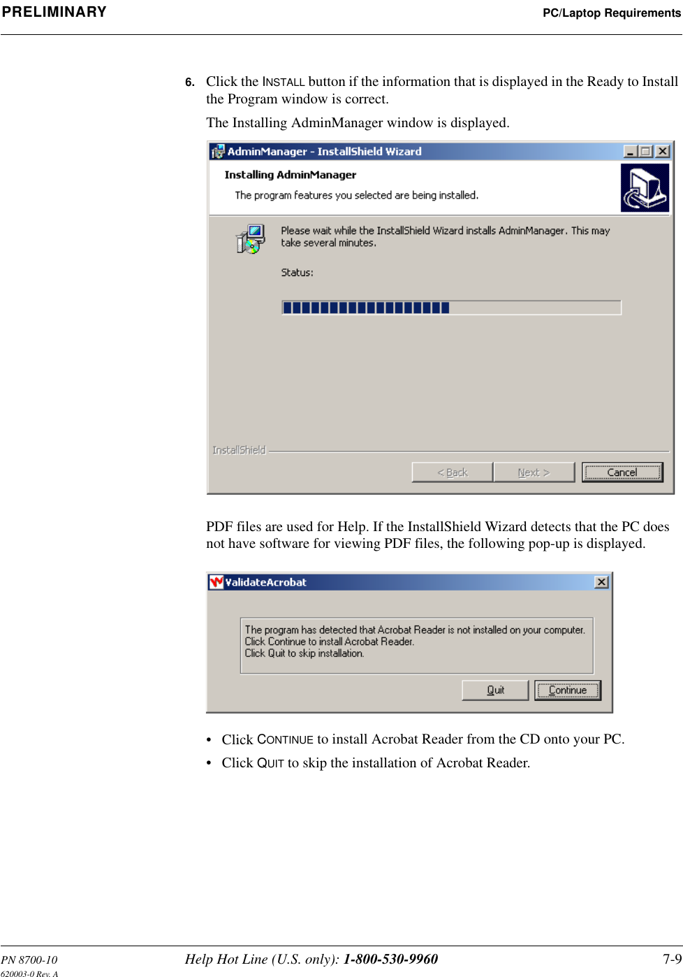
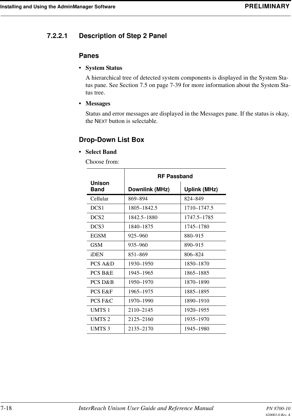
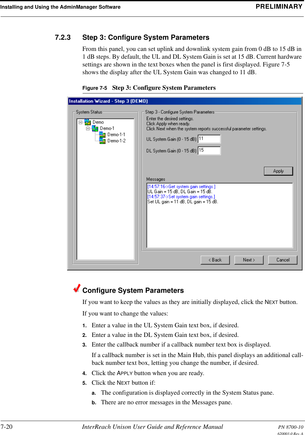
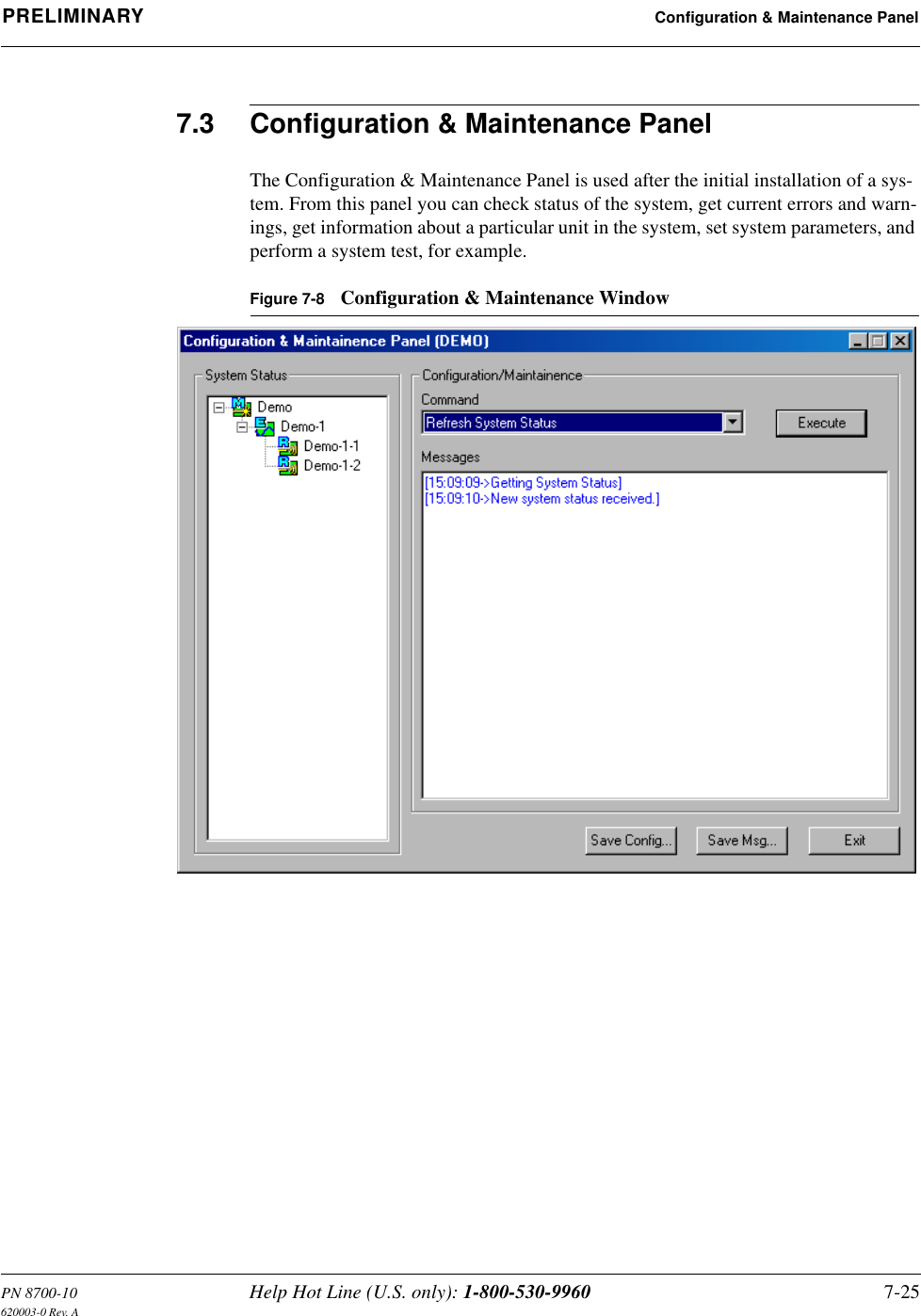
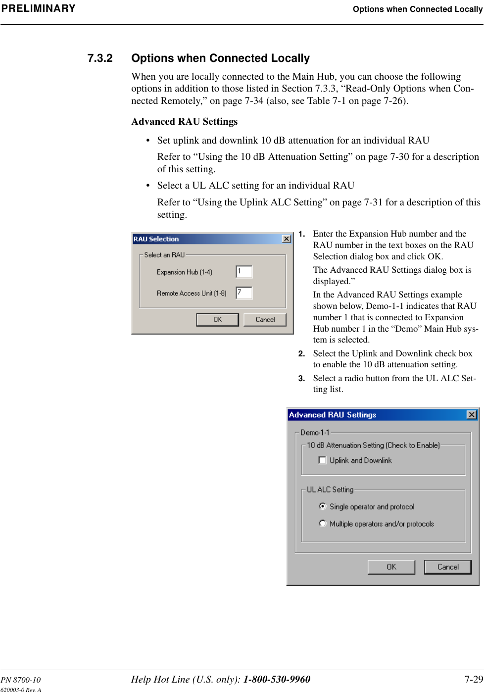
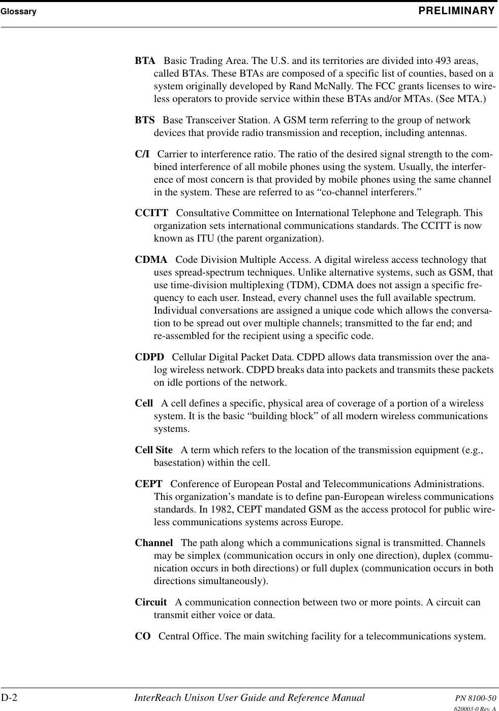
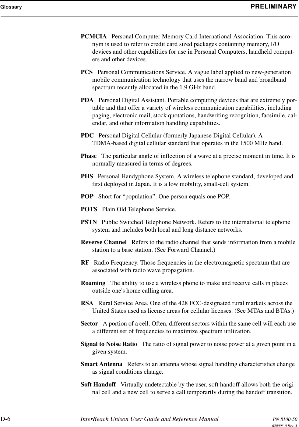
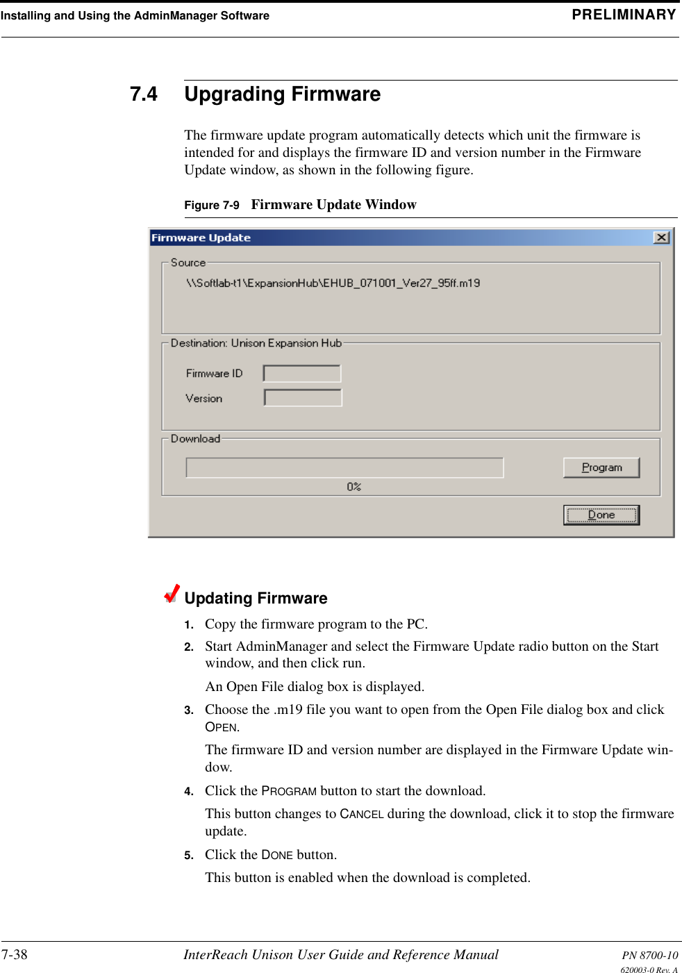
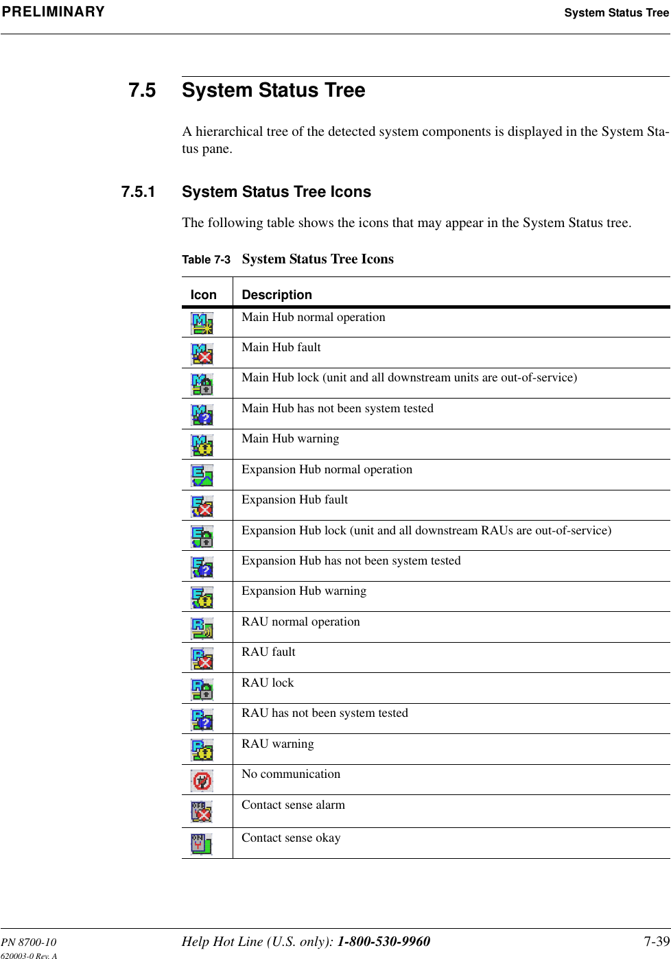
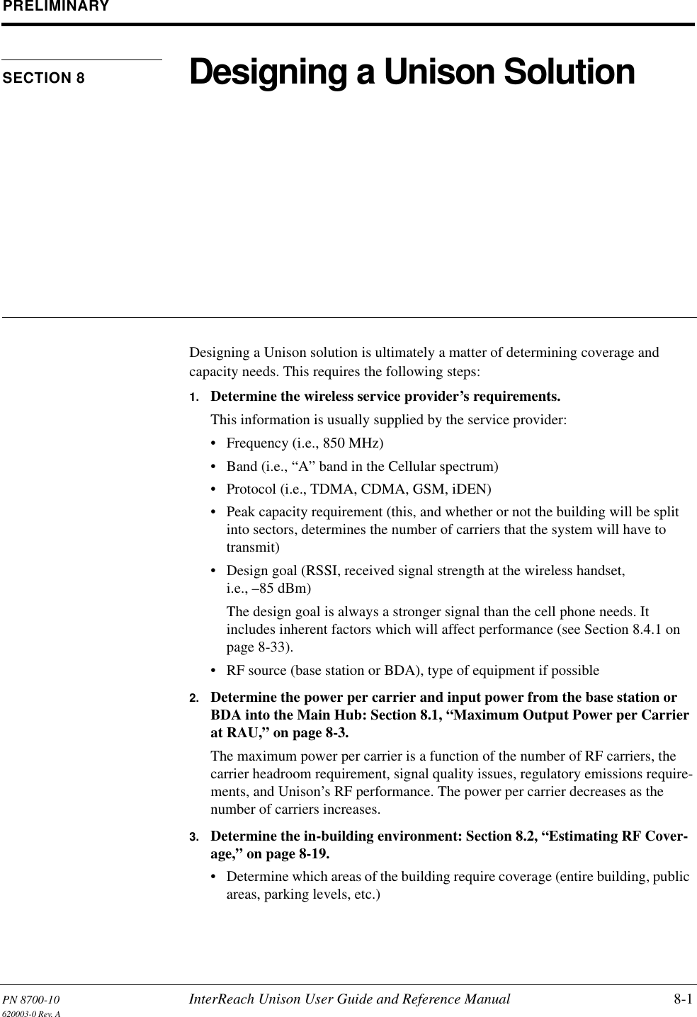
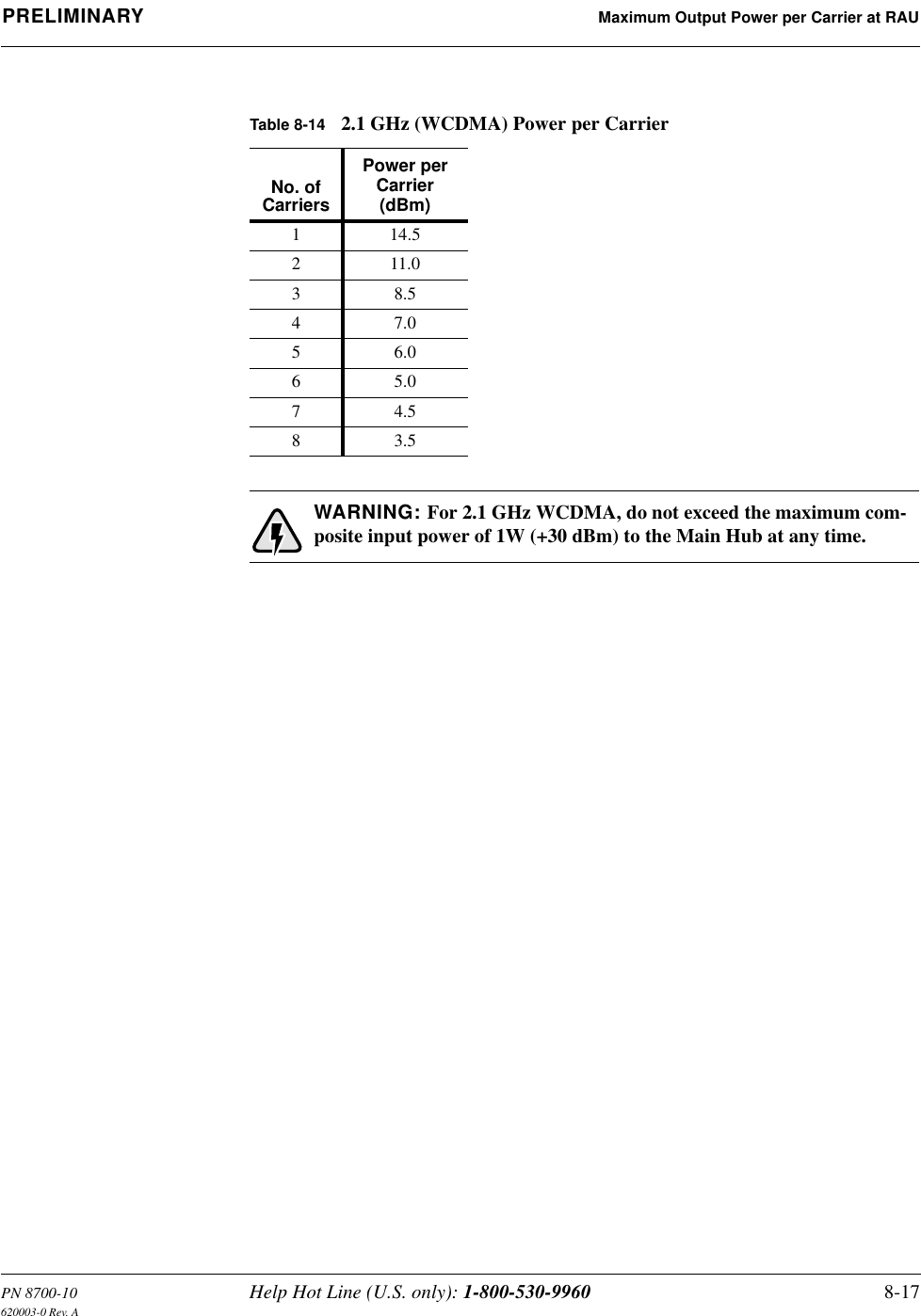
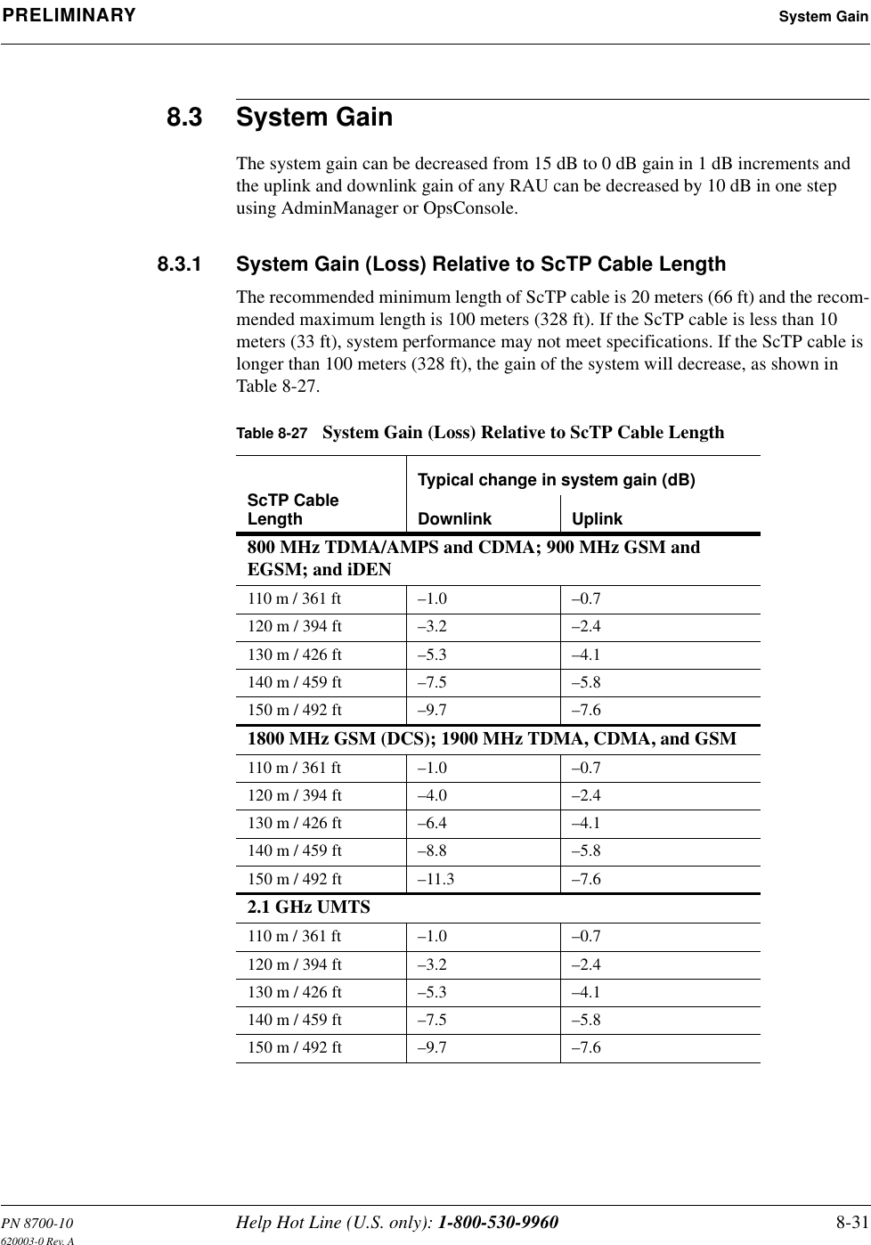
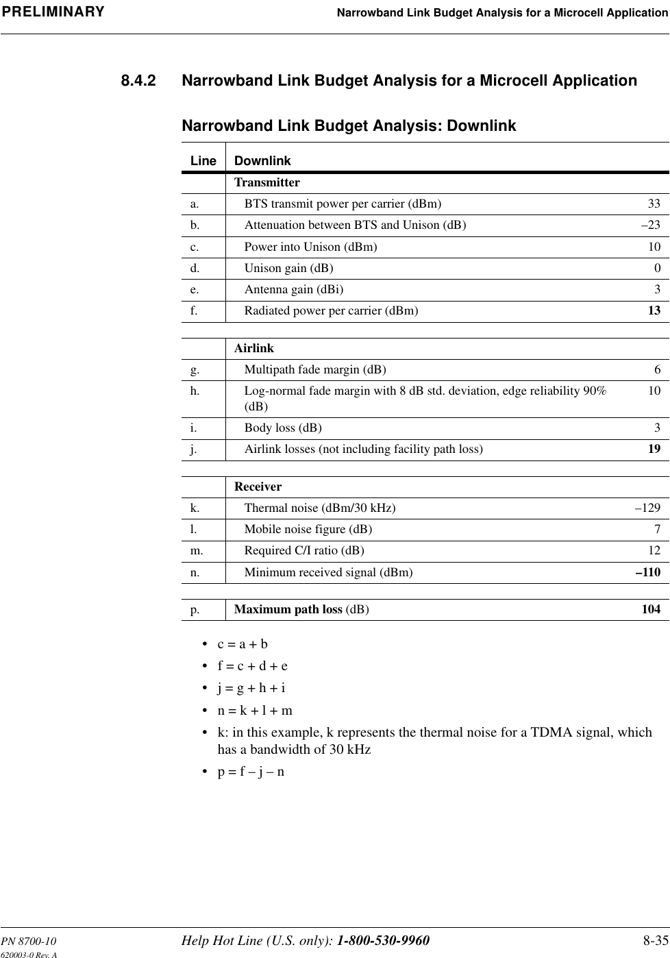
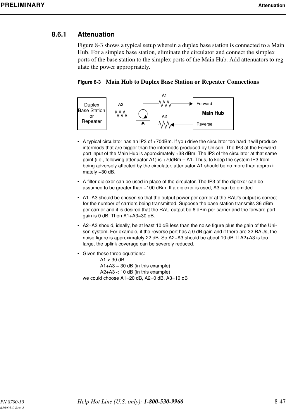
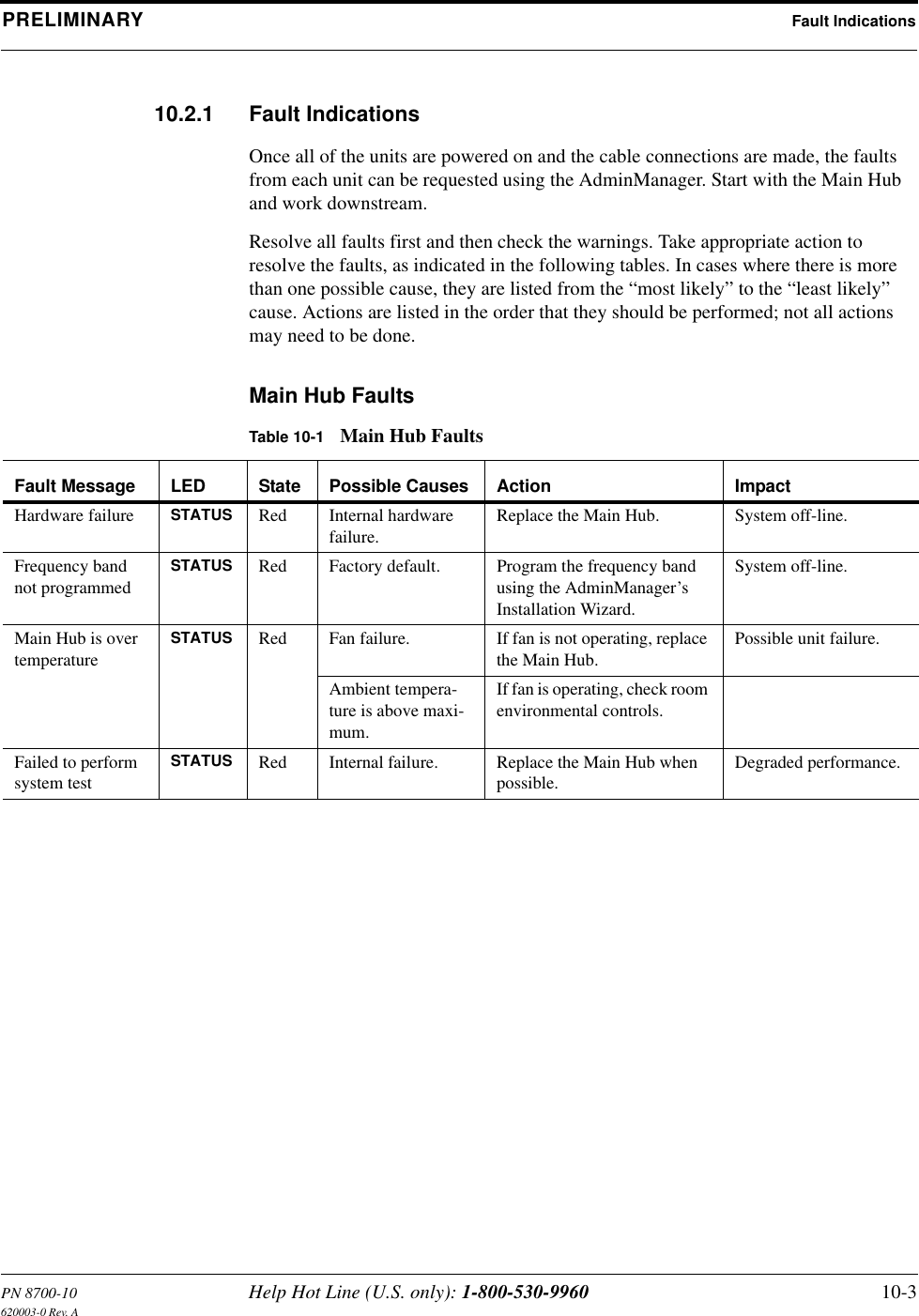
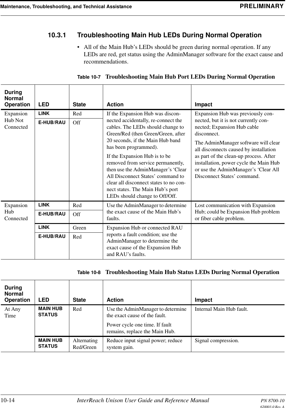
![Installing and Using the AdminManager Software PRELIMINARY7-30 InterReach Unison User Guide and Reference Manual PN 8700-10620003-0 Rev. AUsing the 10 dB Attenuation SettingBy selecting the Uplink and Downlink checkbox in the Advanced RAU Settings dia-log box, the uplink and downlink signals in the individual RAU, which you specified in the RAU Selection dialog box, are both reduced by 10 dB. One reason you may want to use this setting is to reduce the RAU’s output power when an RAU is located near an exterior wall of a building and its RF signal is going beyond the wall to the outside of the building, where it can negatively affect the outdoor macro system.The following table shows some examples of how the 10 dB attenuation setting affects coverage distance. These examples assume a 0 dB gain system, a 3 dBi gain antenna, and the difference between a –85 dB and a –75 dB design.You can use the following formula to calculate the reduction in distance covered.•dorig = original distance•dnew = new distance with 10 dB attenuation enabled• PLS = path loss slope [dB]dnew = (10–10/PLS)dorigExamples:dnew = 0.31 dorig for PLS = 20 dB (free space)dnew = 0.46 dorig for PLS = 30 dBFrequency Environment Reduction in Coverage Distance800 MHz Open, like a parking garage 24 meters (80 feet)800 MHz Heavily walled, like a Hospital 12.5 meters (41 feet)1900 MHz Open, like a parking garage 24 meters (80 feet)1900 MHz Heavily walled, like a Hospital 9 meters (30 feet)](https://usermanual.wiki/ADC-Telecommunications/UNS-IDEN-1.User-Manual-2/User-Guide-173753-Page-30.png)


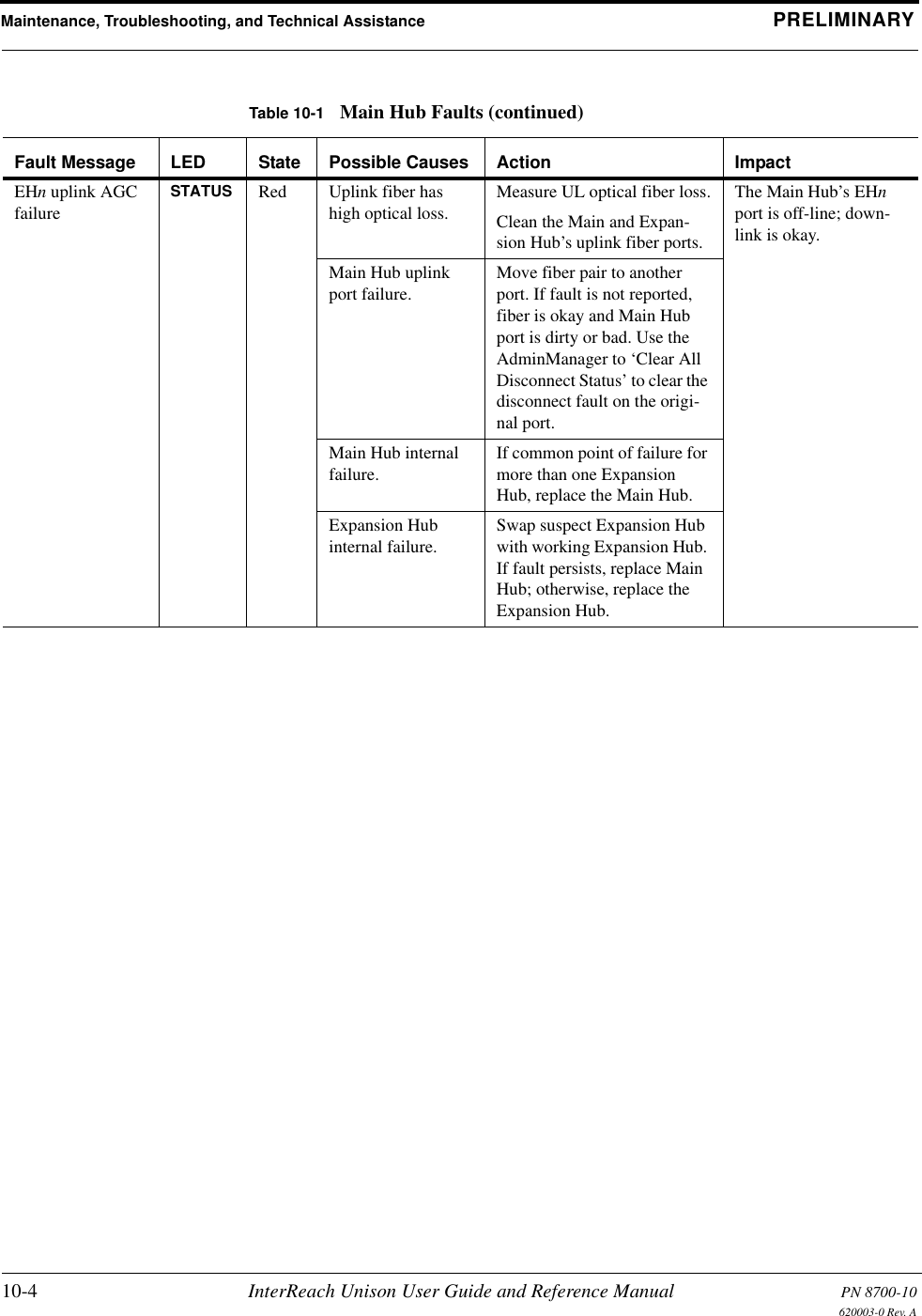
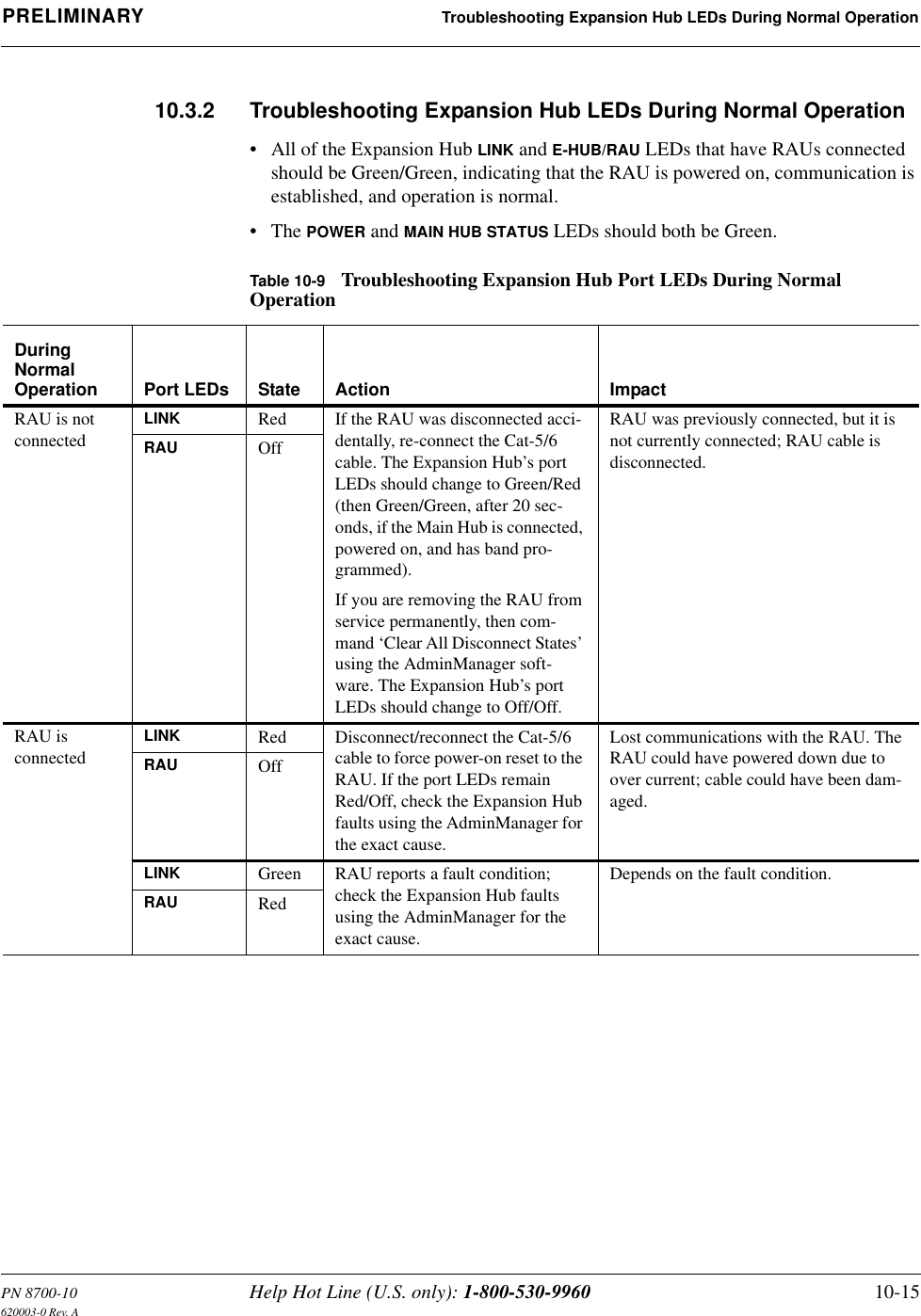

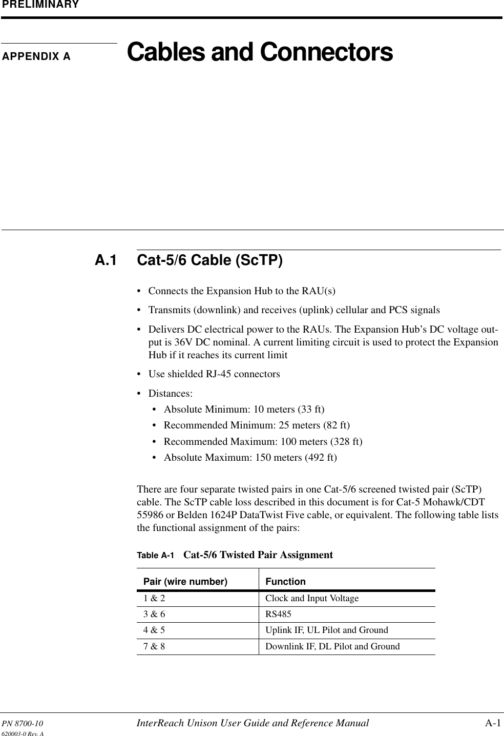
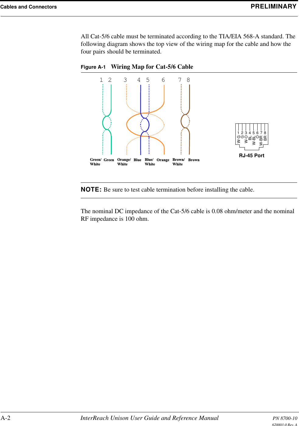
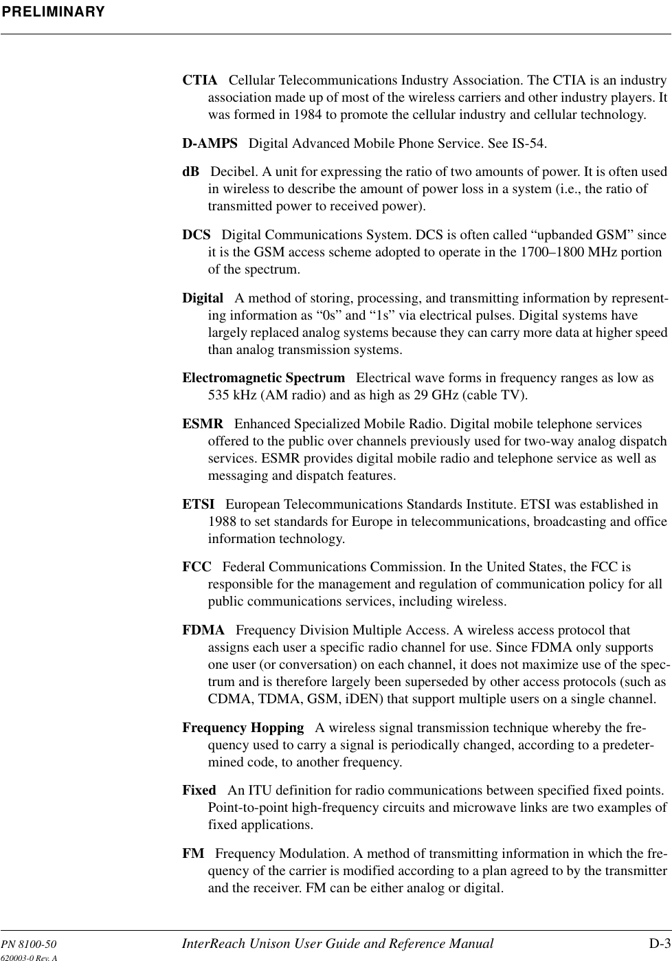
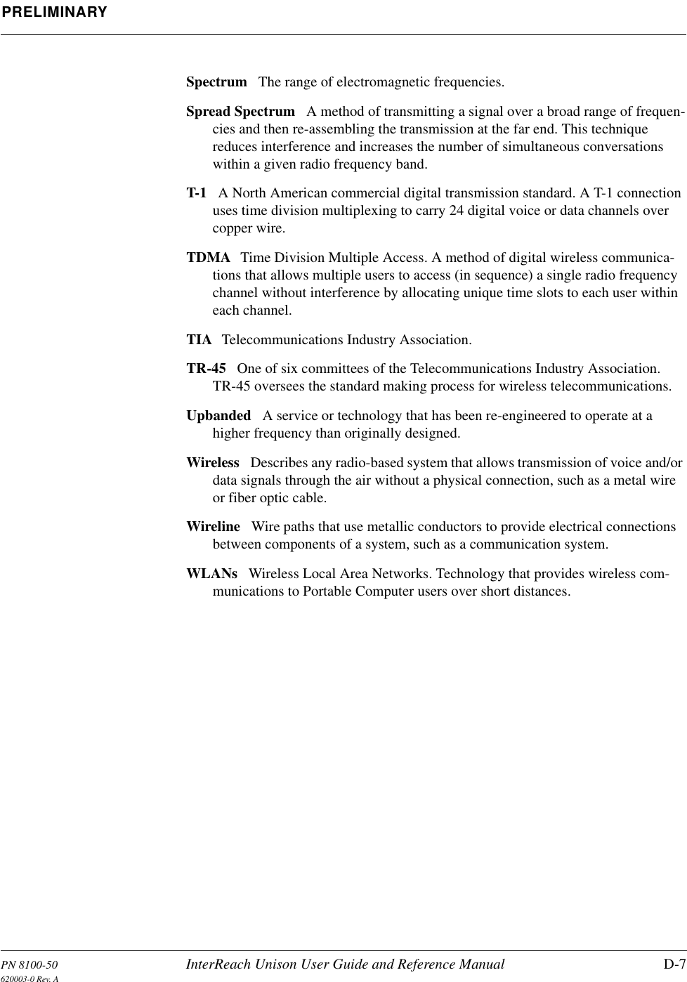
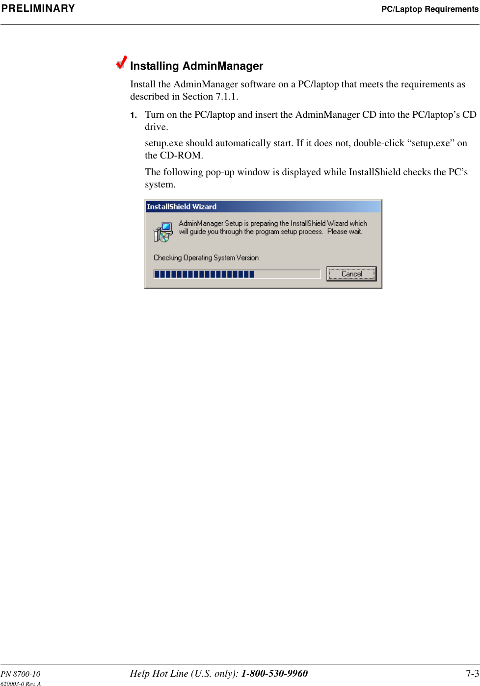
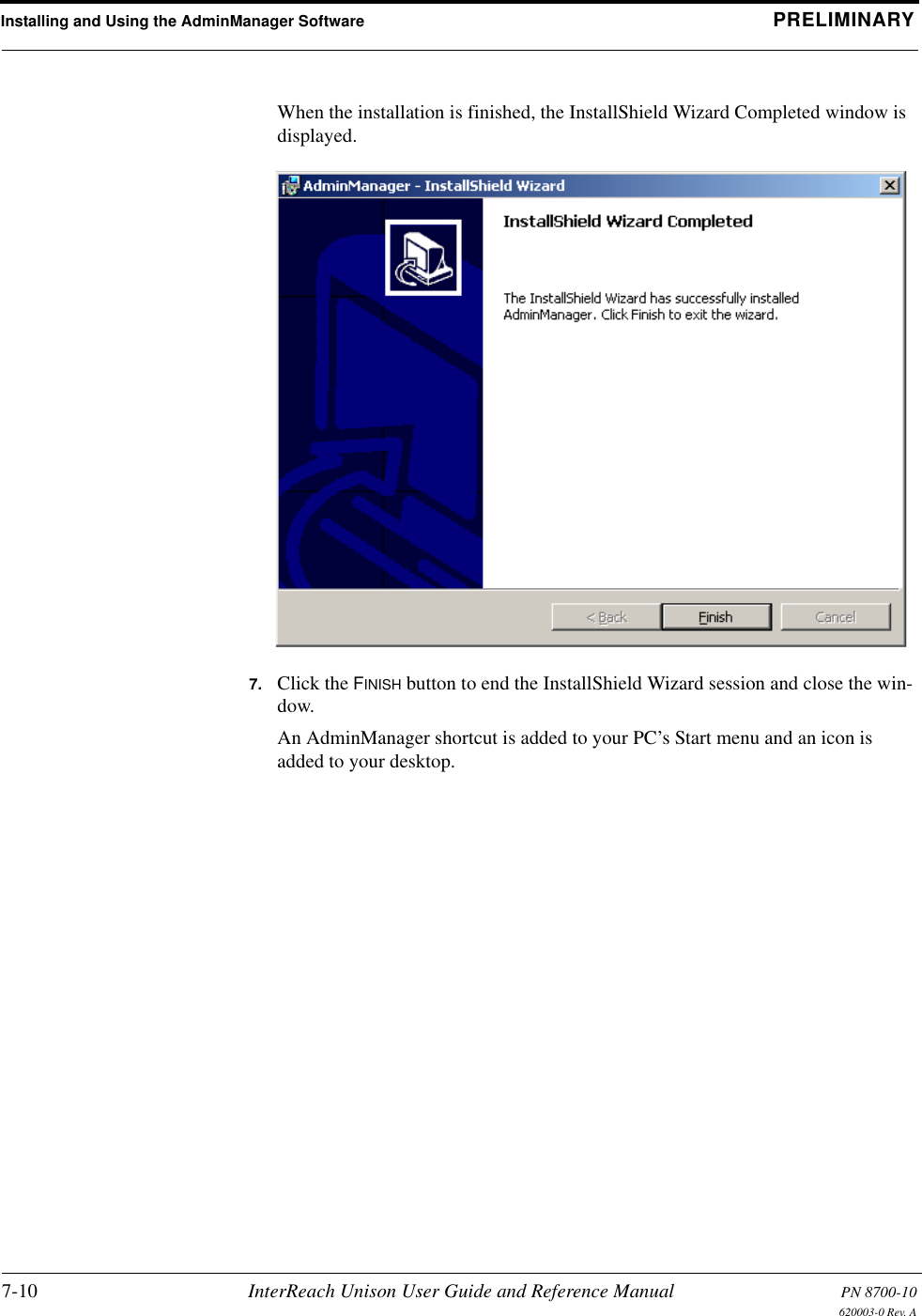
![PN 8700-10 Help Hot Line (U.S. only): 1-800-530-9960 A-3620003-0 Rev. APRELIMINARY Fiber Optical CablesA.2 Fiber Optical Cables• Connects Main Hub to Expansion Hub(s)• Transmits (downlink) and receives (uplink) cellular and PCS signals• Use industry-standard 62.5µm/125µm MMF or Corning SMF-28 fiber, or equiva-lent (SC/APC [angle-polished] connectors only)• Distances:• Multimode Fiber: up to 1.5 km (4,921 ft) – 3 dB optical loss maximum• Single-Mode Fiber: up to 6 km (19,685 ft) – 3 dB optical loss maximumA.3 Coaxial Cable• Connects a Main Hub to a repeater or base station (N-type connectors)• Connects an RAU to a passive antenna (SMA connectors)](https://usermanual.wiki/ADC-Telecommunications/UNS-IDEN-1.User-Manual-2/User-Guide-173753-Page-119.png)