ADRF KOREA ADX-R-SMR DAS (Distributed Antenna System) User Manual ADX DAS
ADRF KOREA, Inc. DAS (Distributed Antenna System) ADX DAS
Contents
- 1. User Manual_Installaion Manual rev Part1
- 2. User Manual_Installaion Manual rev Part2
- 3. User Manual_Installaion Manual rev Part3
User Manual_Installaion Manual rev Part3
Advanced RF Technologies, Inc.
79
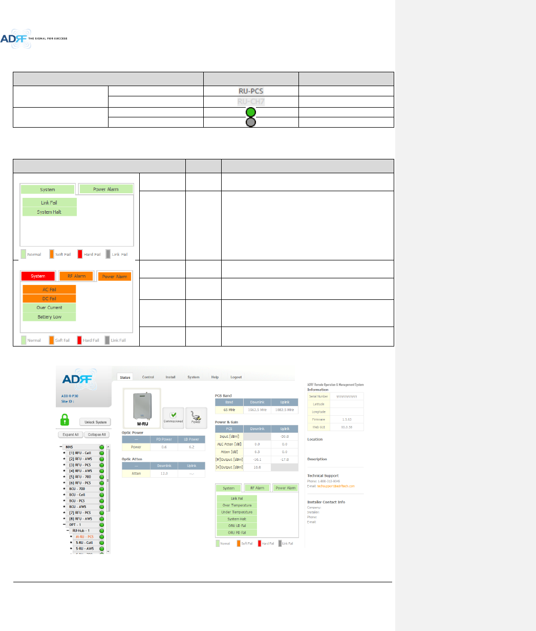
Table 8-11 Description for RU Commissioning status
Status
Display
Description
Installed Status
Installed
Text is black
Not-Installed
Text is gray
Commissioning Status
Success
Green
Fail or not yet
Gray
8.2.2.5.3 Alarm
Table 8-12 Alarm Status (Status - RU Hub)
Alarm
Severity
Description
System
Link Fail
Soft Fail
Present when a module cannot communicate with the
NMS
System Halt
Hard Fail
System will go into a “System Halt” state when a hard
fail alarm does not clear after 10 checks. System Halt
can only be cleared with a power cycle, reboot, or
factory settings.
Power Alarm
AC Fail
Soft Fail
AC power is not within parameters.
DC Fail
Soft Fail
DC power is not within parameters.
Over Current
Hard Fail
Total current of RU is higher than the threshold level for
over current alarm
Battery Low
Soft Fail
Voltage of battery connected to RU PSU is lower than
the defined threshold
8.2.2.6 Status – Remote module
Figure 8-28 Status – Remote Module
Advanced RF Technologies, Inc.
80
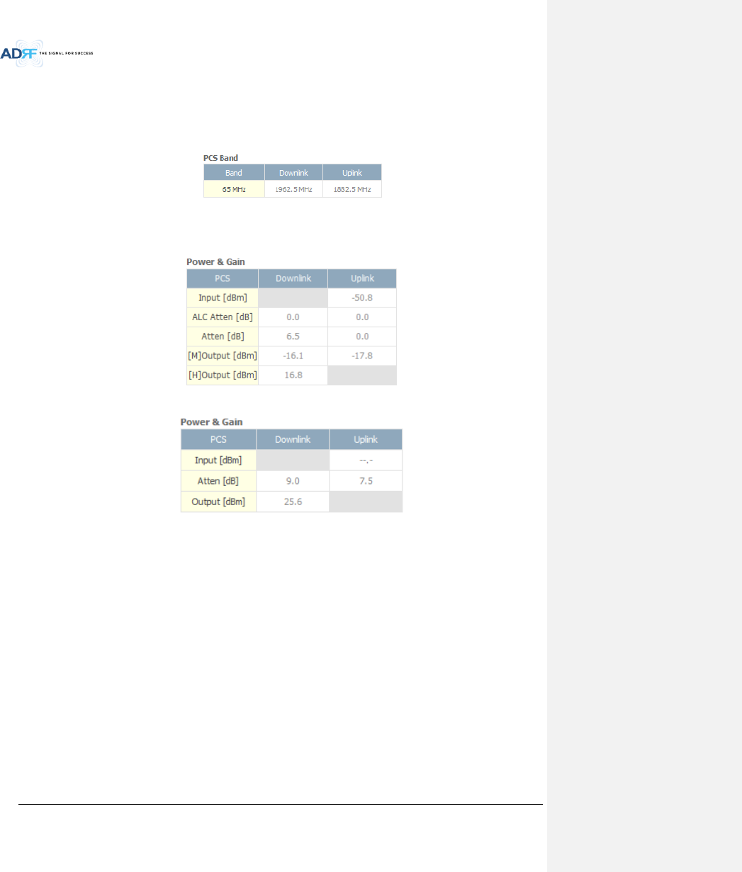
8.2.2.6.1 Band
Display the spectrum that is being used. The band column displays the bandwidth that has been used. The
downlink column displays the center frequency of the used downlink band. The uplink column displays the center
frequency of the used uplink band.
Figure 8-29 PCS Band Information (Status – Remote Module)
8.2.2.6.2 Power & Gain (Admin/User)
Display the Downlink output, Downlink/Uplink Attenuation, and Uplink Input/output.
Figure 8-30 Power & Gain (Admin)
Figure 8-31 Power & Gain (User)
Admin
o Input [dBm]: Displays the RF input level for Uplink only for the Remote Module.
o ALC Atten [dB]: The amount of attenuation used when ALC is activate.
o Atten [dB]: The amount of attenuation manually set by the user.
o [M]Output [dBm]: Output power of RF transceiver (1st stage amplification).
o [H]Output [dBm]: Output power of downlink HPA (2nd stage amplification).
User
o Input [dBm]: Displays the RF input level for Uplink only for the Remote Module.
o Atten [dB]: The amount of attenuation manually set by the user.
o Output [dBm]: Displays the total composite output power.
Advanced RF Technologies, Inc.
81
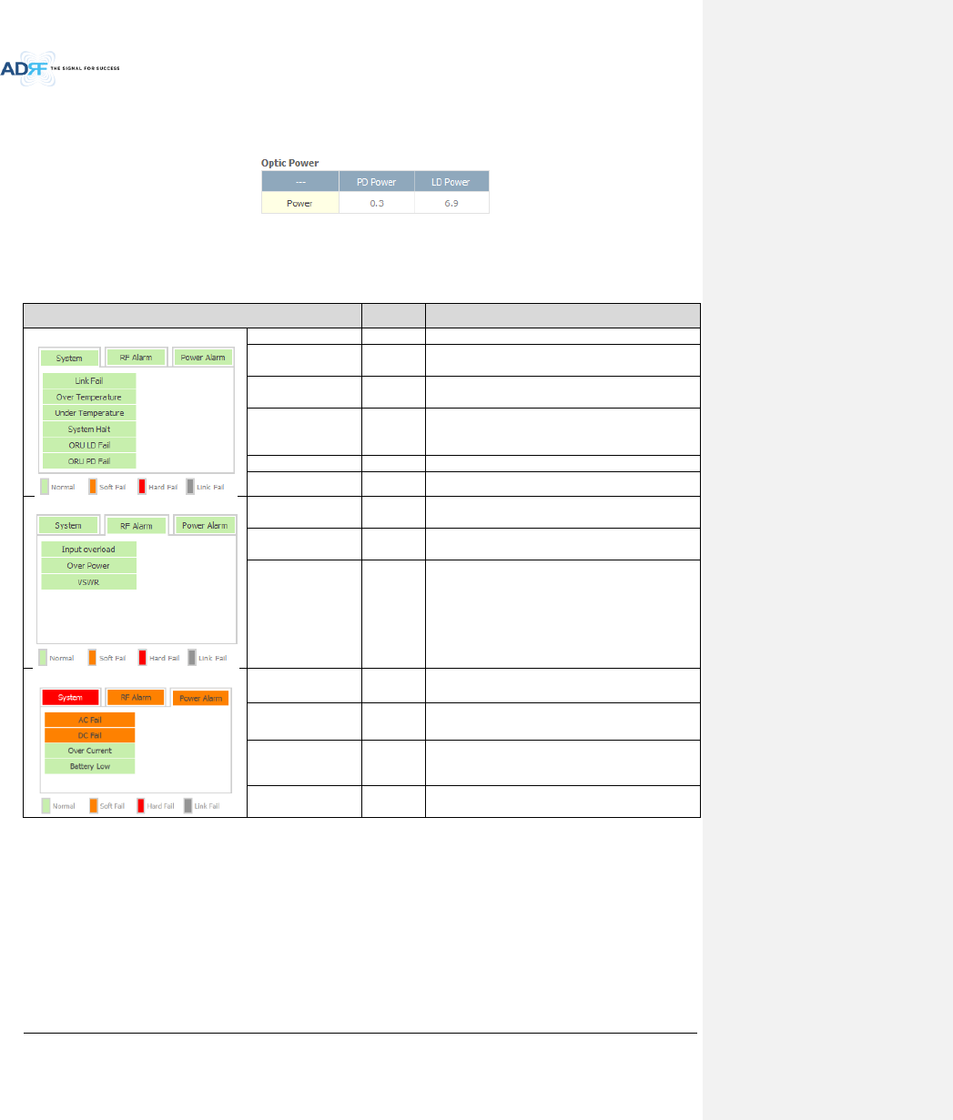
8.2.2.6.3 Optic Power (Master-RU Only)
Display the LD Power and PD Power of optic module inside the Master RU.
Figure 8-32 Optic Power (Status – Master RU only)
8.2.2.6.4 Operating Status
Table 8-13 Operating Status (Status – Remote Module)
Alarm
Severity
Description
System
Link Fail
Soft Fail
No communication with NMS.
Over Temperature
Hard Fail
/ Soft Fail
Temperature is higher than the threshold level for
over temperature alarm.
Under
Temperature
Soft Fail
Temperature is lower than the threshold level for
under temperature alarm.
System Halt
Hard Fail
System halt on either the Master RU or Slave RU.
System halt occurs when a hard fail alarm fails to
clear after 10 checks.
ORU LD Fail
Soft Fail
LD Fail present in the Master RU’s optic unit.
ORU PD Fail
Soft Fail
PD Fail present in the Master RU’s optic unit.
RF Alarm
Input Overload
Hard Fail
Uplink input signal is higher than the defined
threshold.
Over Power
Hard Fail
/ Soft Fail
Downlink output signal is higher than the defined
threshold by user.
VSWR
Soft Fail
Triggered when power is being reflected back to
the system, typically due to a loose connector.
Power Alarm
AC Fail
Soft Fail
AC power is not operating within parameters.
DC Fail
Soft Fail
DC power is not operating within parameters.
Over Current
Hard Fail
Total current of RU is higher than the threshold
level for over current alarm.
Battery Low
Soft Fail
Voltage of battery connected to HE PSU is lower
than the defined threshold.
Advanced RF Technologies, Inc.
82
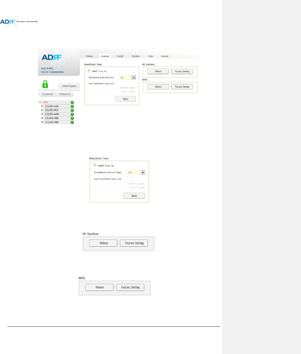
8.2.3 Control Tab
8.2.3.1 Control – NMS
Figure 8-33 Control - NMS
8.2.3.1.1 Heartbeat Time
Allows the user to enable or disable SNMP traps from being sent out and also specify the Heartbeat interval.
Time and date stamps of the last 2 heartbeats will be displayed in the “Last heartbeat sent out” section.
Figure 8-34 Heartbeat (Control – NMS)
8.2.3.1.2 HE System
Allows the user to perform a HE system reboot or HE full system factory settings
Figure 8-35 HE System Reboot & Factory Setting (Control – NMS)
8.2.3.1.3 NMS System
Allows the user to perform a NMS Unit reboot or NMS factory settings
Figure 8-36 NMS System Reboot & Factory Setting (Control – NMS)
Advanced RF Technologies, Inc.
83
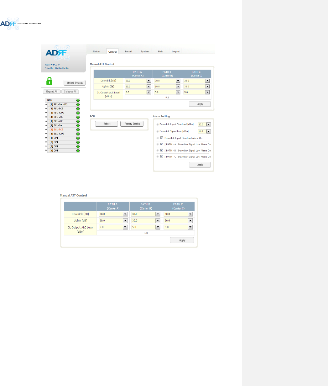
8.2.3.2 Control – BCU
Figure 8-37 Control – BCU
8.2.3.2.1 Manual ATT Control
Figure 8-38 Control – BCU Manual ATT Control
Downlink: Allows the user to manually adjust the DL attenuation levels for each RF path. Adjusting
these settings is not recommended since it will change the power ratios set by the user.
Uplink: Allows the user to manually adjust the UL attenuation levels for each RF path. Adjusting these
settings is not recommended, unless additional attenuation is needed on the UL path.
DL Output ALC Level: Allows the user to manually set the DL Output ALC Levels for each RF path.
Adjusting these settings is not recommended since it will change the power ratios set by the user.
These settings are automatically set by the system during the BCU commissioning process. This
section also displays the composite DL Output ALC Level which is the value that can be used to
commission the RFU.
Advanced RF Technologies, Inc.
84
8.2.3.2.2 Reboot / Factory Setting
Allows the user reboot or restore factory settings of the BCU.
Figure 8-39 Control – BCU Reboot/Factory Setting
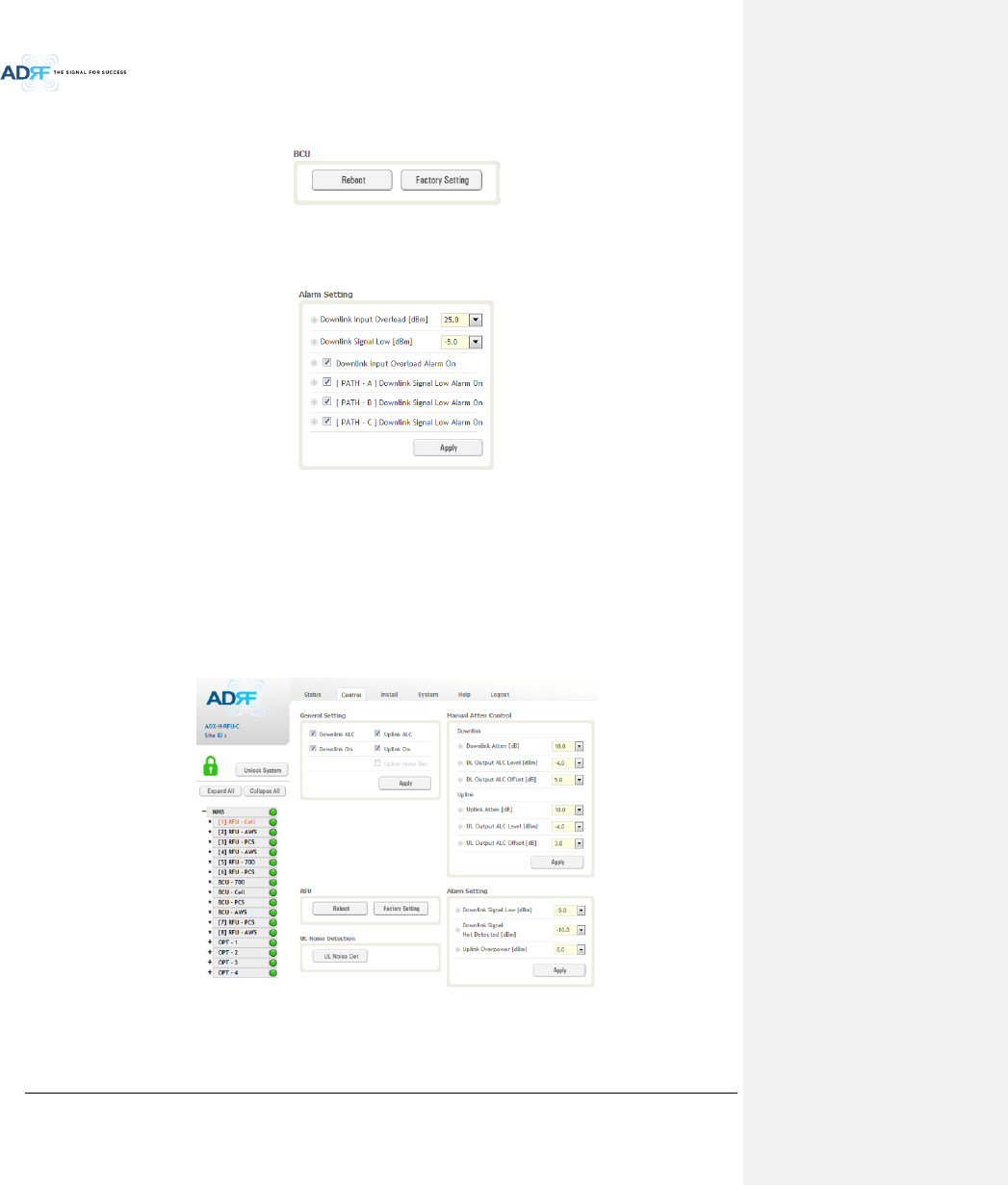
8.2.3.2.3 Alarm Setting
Figure 8-40 Control – BCU Alarm Setting
Downlink Input Overload: Allows the user to specify the level at which the DL Input Overload alarm is
triggered. Values range from 0 dBm to +25 dBm.
Downlink Signal Low: Allows the user to specify the level at which the DL Signal Low alarm is triggered.
Values range from -10 dBm to +20 dBm.
Downlink Input Overload Alarm On: Allows to user to enable or disable the Input Overload Alarm
[Path – A/B/C] Downlink Signal Low Alarm On: Allows the user to enable or disable the DL Signal Low
alarm for each RF path.
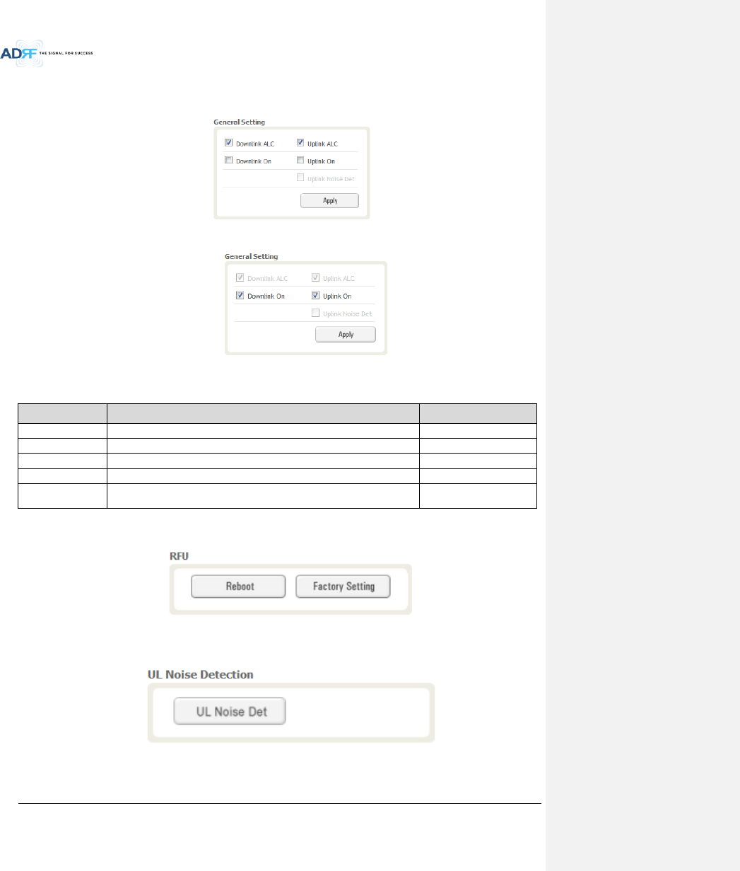
8.2.3.3 Control – RFU
Figure 8-41 Control - RFU
Advanced RF Technologies, Inc.
85
8.2.3.3.1 General Setting
To enable any of the settings, click on the checkbox and click the Apply button.
Figure 8-42 General Setting (Control – RFU) (Admin)
Figure 8-43 General Setting (Control – RFU) (User)
Table 8-14 Description for General Setting
Name
Description
Available Accounts
Downlink ALC
Enables or disables Downlink ALC
Administrator
Uplink ALC
Enables or disables Uplink ALC
Administrator
Downlink ON
Enables or disables the RFU Downlink path
Administrator, User
Uplink ON
Enables or disables the RFU Uplink path
Administrator, User
Uplink Noise Det
Displays if the module is turned on or off due to the UL Noise Detection
Routine
Administrator
8.2.3.3.2 Reboot / Factory Setting
Allows the user reboot or restore factory settings of the RFU.
Figure 8-44 Reboot & Factory Setting (Control – RFU)
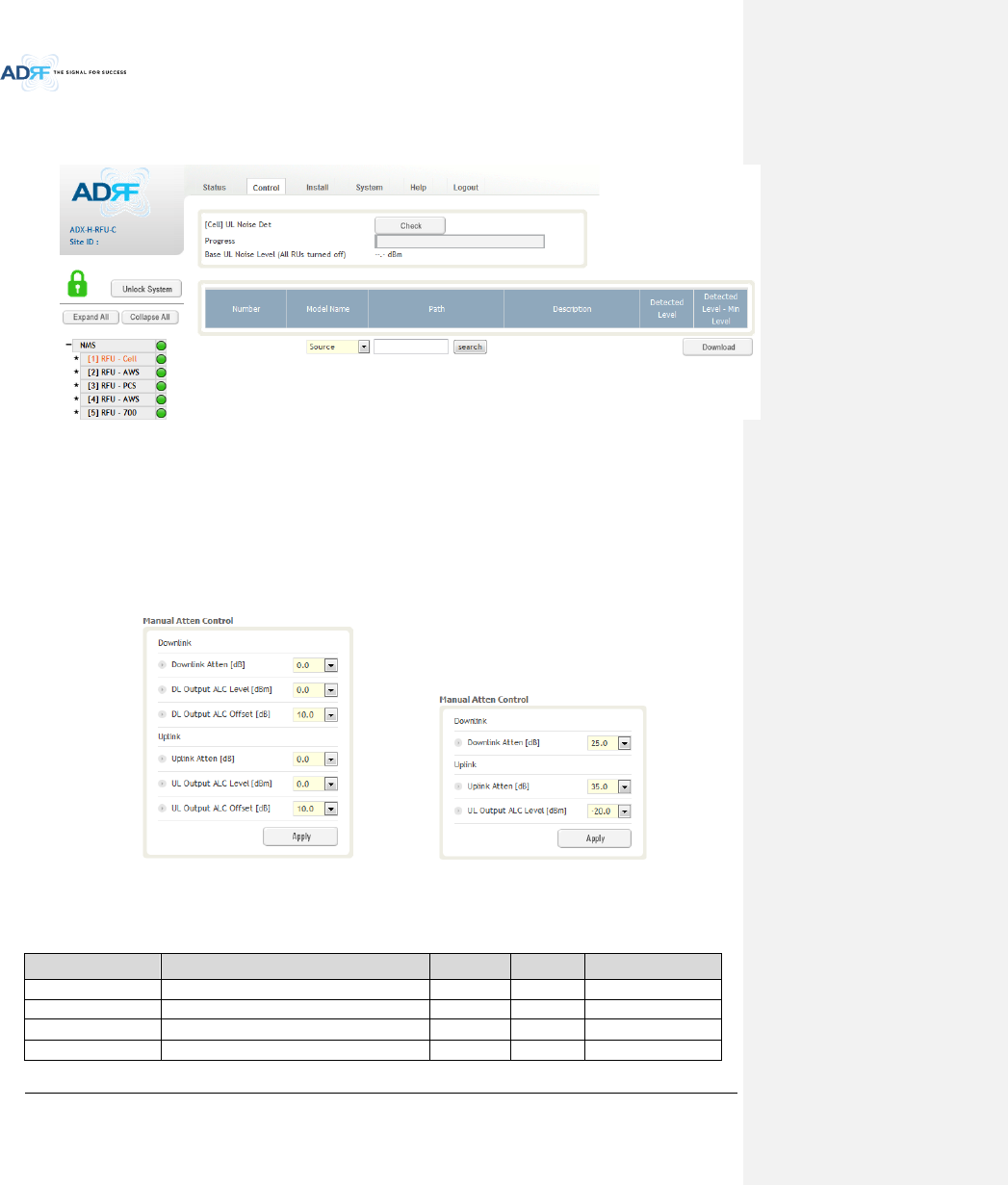
8.2.3.3.3 Uplink Noise Detection (Admin Only)
Figure 8-45 UL Noise Detection (Control – RFU)
Advanced RF Technologies, Inc.
86
The “UL Noise Det” button will take you to the UL Noise Detection page which will allow you to run the UL Noise
Detection routine.
Figure 8-46 UL Noise Detection - PCS band
The Auto UL noise measurement routine can be run by clicking on the Check button. After all UL noise
measurement have been taken, the levels for each UL path will be displayed and along with the difference
between minimum detect level and measured detect level.
The user will be able to see which path is generating the elevated UL noise level based on the measured detect
level and difference value.
To navigate back to the RFU control page, click on the Control tab again.
8.2.3.3.4 Manual Atten Control
(Admin) (User)
Figure 8-47 Manual Attenuator Control Setting (Control – RFU)
Table 8-15 Description for Main Gain Control Setting (Control – RFU)
Name
Description
Range
Step
Available Accounts
Downlink Atten
Downlink Attenuator to be adjusted manually
0 ~ 25dB
0.5dB
Administrator, User
Uplink Atten
Uplink Attenuator to be adjusted manually
0 ~ 35dB
0.5dB
Administrator, User
DL Output ALC Level
To set the Max output ALC level
-10 ~ 0dBm
0.5dBm
Administrator
UL Output ALC Level
To set the Max output ALC level
-20 ~ 0dBm
0.5dBm
Administrator, User
Advanced RF Technologies, Inc.
87
DL Output ALC Offset
To set the Max output ALC Offset
-10 ~ 0dBm
0.5dBm
Administrator
UL Output ALC Offset
To set the Max output ALC Offset
-20 ~ 0dBm
0.5dBm
Administrator
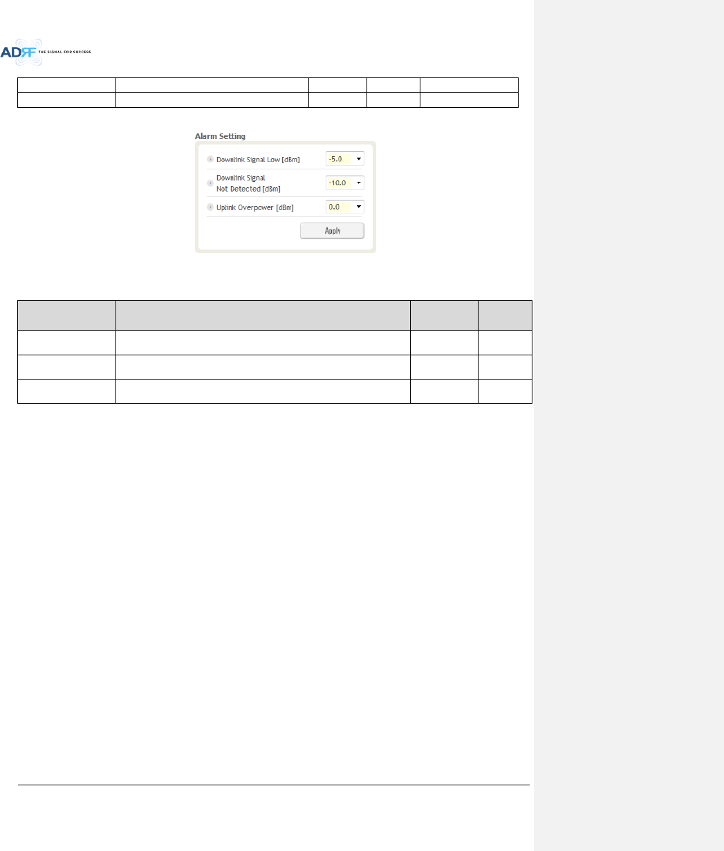
8.2.3.3.5 Alarm Setting
Figure 8-48 Alarm Threshold Setting (Control – RFU)
Table 8-16 Description for Alarm Threshold Setting (Control – RFU)
Name
Description
Range
Default
threshold
Downlink Signal Low
Allows the user to specify the minimum incoming DL input signal level
before triggering a “Downlink Signal Low” soft-fail alarm.
-10 ~ 20dBm
-5dBm
Downlink Signal Not
Detected
Allows the user to specify the minimum incoming DL input signal level
before triggering a “Downlink Signal Not Detected” soft-fail alarm.
-10 ~ 20dBm
-10dBm
Uplink Over Power
Allows the user to specify the how strong the output signal of uplink can
be before triggering an “Uplink Over Power” Hard Fail alarm.
-20 ~ 0dBm
0dBm
Advanced RF Technologies, Inc.
88
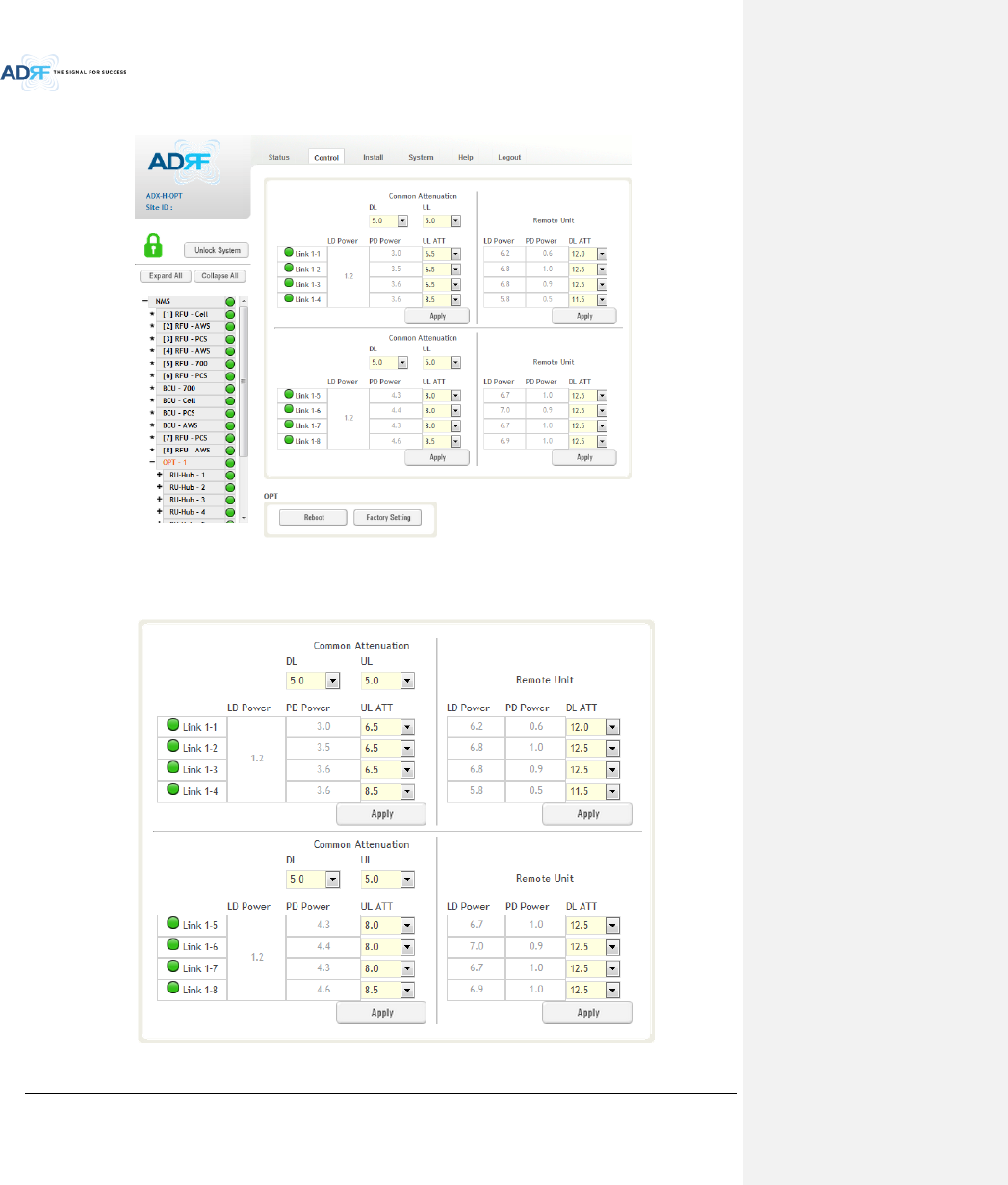
8.2.3.4 Control – ODU
Figure 8-49 Control – OPT
8.2.3.4.1 Optic Attenuation (Admin Only)
Figure 8-50 Optic Attenuation – OPT
Advanced RF Technologies, Inc.
89
Table 8-17 Description for Optic Attenuation (Control – OPT)
Name
Description
Range
Default
threshold
DL/UL common ATT
Allows the user to control overall optic DL/UL path gain.
0 ~ 30dB
5dB
DL ATT
Used to compensate DL optic loss.
0 ~ 13dB
13dB
UL ATT
Used to compensate UL optic loss.
0 ~ 13dB
13dB
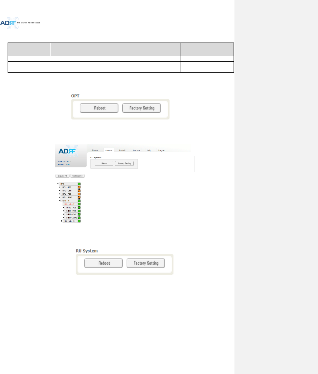
8.2.3.4.2 Reboot/Factory Setting
Allows the user to perform ODU reboot or ODU factory settings.
Figure 8-51 Reboot & factory Setting (Control – OPT)
8.2.3.5 Control – RH Hub
Figure 8-52 Control – RU Hub
8.2.3.5.1 Reboot/Factory Setting
Allows the user to perform RU Hub reboot or RU Hub factory settings
Figure 8-53 Reboot & Factory Setting (Control – RU Hub)
Advanced RF Technologies, Inc.
90
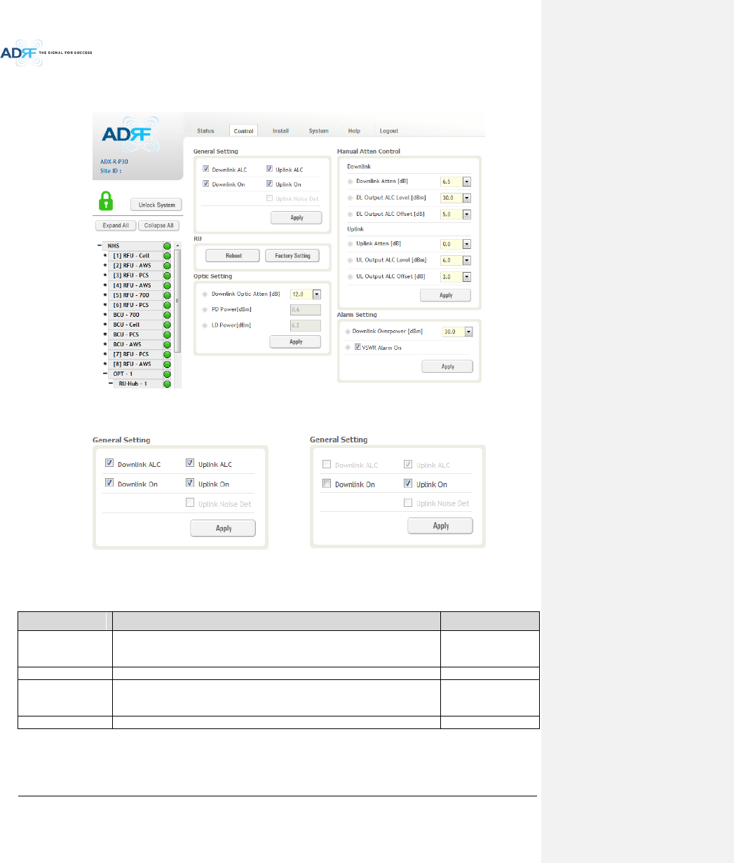
8.2.3.6 Control – Remote Module (Master or Slave RU)
Figure 8-54 Control – Remote Module
8.2.3.6.1 General Setting (Admin/User)
(Admin) (User)
Figure 8-55 General Setting (Control - RU)
Table 8-18 Description for General Setting (Control - RU)
Name
Description
Available Accounts
Downlink ALC
This setting allows you to enable or disable the downlink ALC function. When
ALC is enabled, the downlink output power will not exceed the Downlink
Output Level specified in the Manual Atten Control section.
Administrator
Downlink On
This setting allows you to enable or disable the Downlink path.
Administrator, User
Uplink ALC
This setting allows you to enable or disable the uplink ALC function. When ALC
is enabled, the Uplink output power will not exceed the Uplink Output Level
specified in the Manual Atten Control section.
Administrator
Uplink On
This setting allows you to enable or disable the Uplink path.
Administrator, User
Advanced RF Technologies, Inc.
91
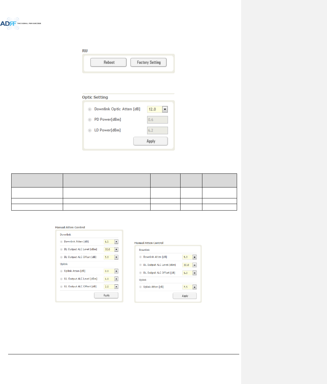
8.2.3.6.2 Reboot/Factory Setting
Allows the user to Reboot or restore Factory Settings on the remote module.
Figure 8-56 Reboot & factory Setting (Control - RU)
8.2.3.6.3 Optic Setting (Only Master RU) (Admin Only)
Figure 8-57 Optic Setting (Control - RU)
Table 8-19 Description for Optic Setting (Control - RU)
Name
Description
Range
Step
Available
Accounts
Downlink Optic Atten
RF attenuator to compensate the optic loss of
downlink
0~ 13.0 dB
0.5 dB
Administrator
PD Power
Incoming power level from the ODU
Administrator
LD Power
Outgoing power level to the ODU
Administrator
8.2.3.6.4 Manual Attenuator Control
(Admin) (User)
Figure 8-58 Manual Atten Control (Control - RU)
Advanced RF Technologies, Inc.
92
Table 8-20 Description for Manual Atten Control (Control - RU)
Name
Description
Range
Default
threshold
Available Accounts
Downlink Atten
Allows the user to specify how much attenuation to use.
0 ~ 30dB
30dB
Administrator, User
Uplink Atten
Allows the user to specify how much attenuation to use.
0 ~ 25dB
25dB
Administrator, User
DL Output ALC
Level
The remote module will prevent the downlink output
power from exceeding the specified value.
5 ~ 30dB
30dBm
Administrator, User
UL Output ALC
Level
The system will prevent the output power to exceed the
specified value.
0 ~ 10dBm
5 or
6dBm
Administrator
DL Output ALC
Offset
When the incoming signal level increases, the system will
not adjust the gain levels until it reaches the ALC Offset
Level.
0 ~ 10dB
5dB
Administrator, User
UL Output ALC
Offset
When the incoming signal level increases, the system will
not adjust the gain levels until it reaches the ALC Offset
Level.
0 ~ 10dB
3dB
Administrator
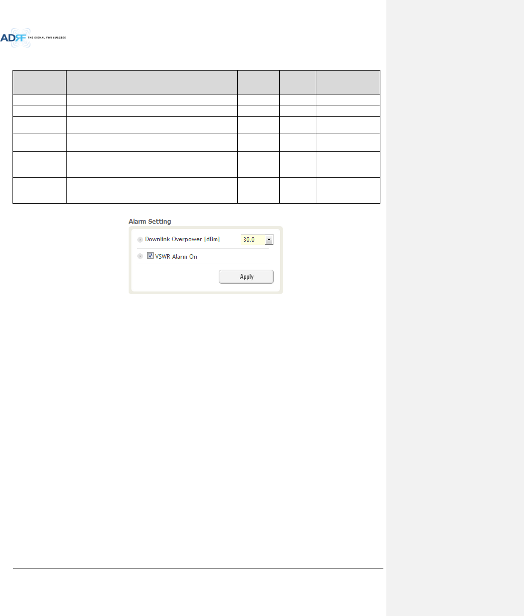
8.2.3.6.5 Alarm Setting
Figure 8-59 Alarm Setting (Control - RU)
DL Over Power Limit: The overpower alarm threshold can be adjusted from 5~30dBm. +2dB from the DL
overpower limit will trigger a soft fail and >2dB will trigger a hard fail alarm
VSWR Alarm ON : Enable or disables the VSWR Alarm.
Advanced RF Technologies, Inc.
93
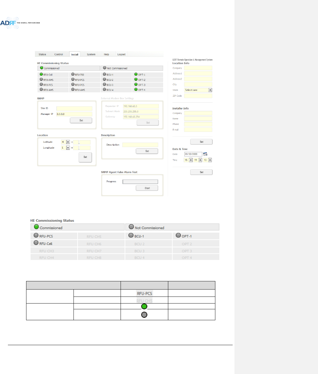
8.2.4 Install Tab
8.2.4.1 Install – NMS
Figure 8-60 Install - NMS
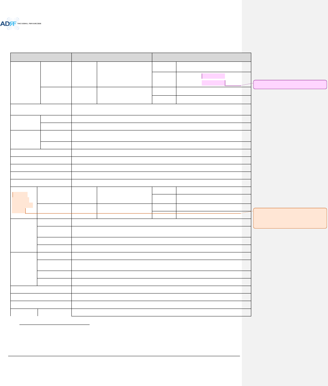
8.2.4.1.1 HE Commissioning Status
Figure 8-61 HE Commissioning Status (Install – NMS)
Table 8-21 Description for HE Commissioning Status (Install – NMS)
Status
Display
Description
Installed Status
Physically Installed
Text is black
Physically Not-Installed
Text is gray
Commissioning Status
Success
Green
Fail or not
commissioned
Gray
Advanced RF Technologies, Inc.
94
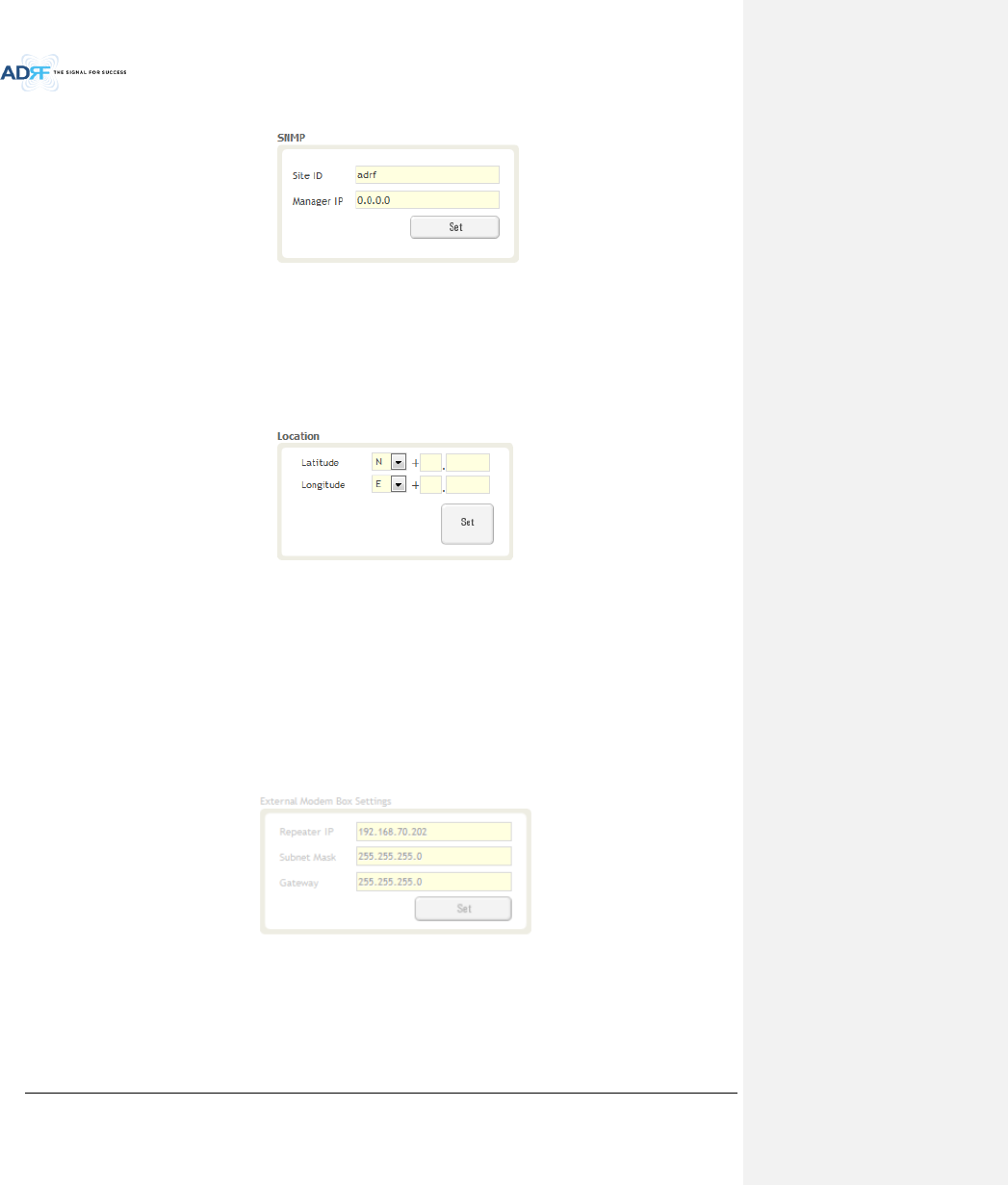
8.2.4.1.2 SNMP
Figure 8-62 SNMP (Install – NMS)
The SNMP section allows you to specify the Site ID and Manager IP. The Site-ID is the code that is used to
identify a particular module. The Manager IP field is where the user inputs the IP address of the NOC system that
is being used to monitor the SNMP traps.
8.2.4.1.3 Location
This section allows the user to input the latitude and the longitude of the repeater.
Figure 8-63 Location Setting (Install – NMS)
Select N or S from the dropdown menu for Latitude
Select E or W from the dropdown menu for Longitude
Input the first 3 numbers of the latitude/longitude in the text area after the “+” and before the “.”
Input the last 6 numbers of the latitude/longitude in the text area after the “.”
8.2.4.1.4 External Modem Box Settings
This section allows the user to specify an alternative IP, Subnet Mask, and Gateway settings. These settings
are enabled when the Host/Remote switch is set to the Remote position.
Figure 8-64 External Modem Box Setting (Install – NMS)
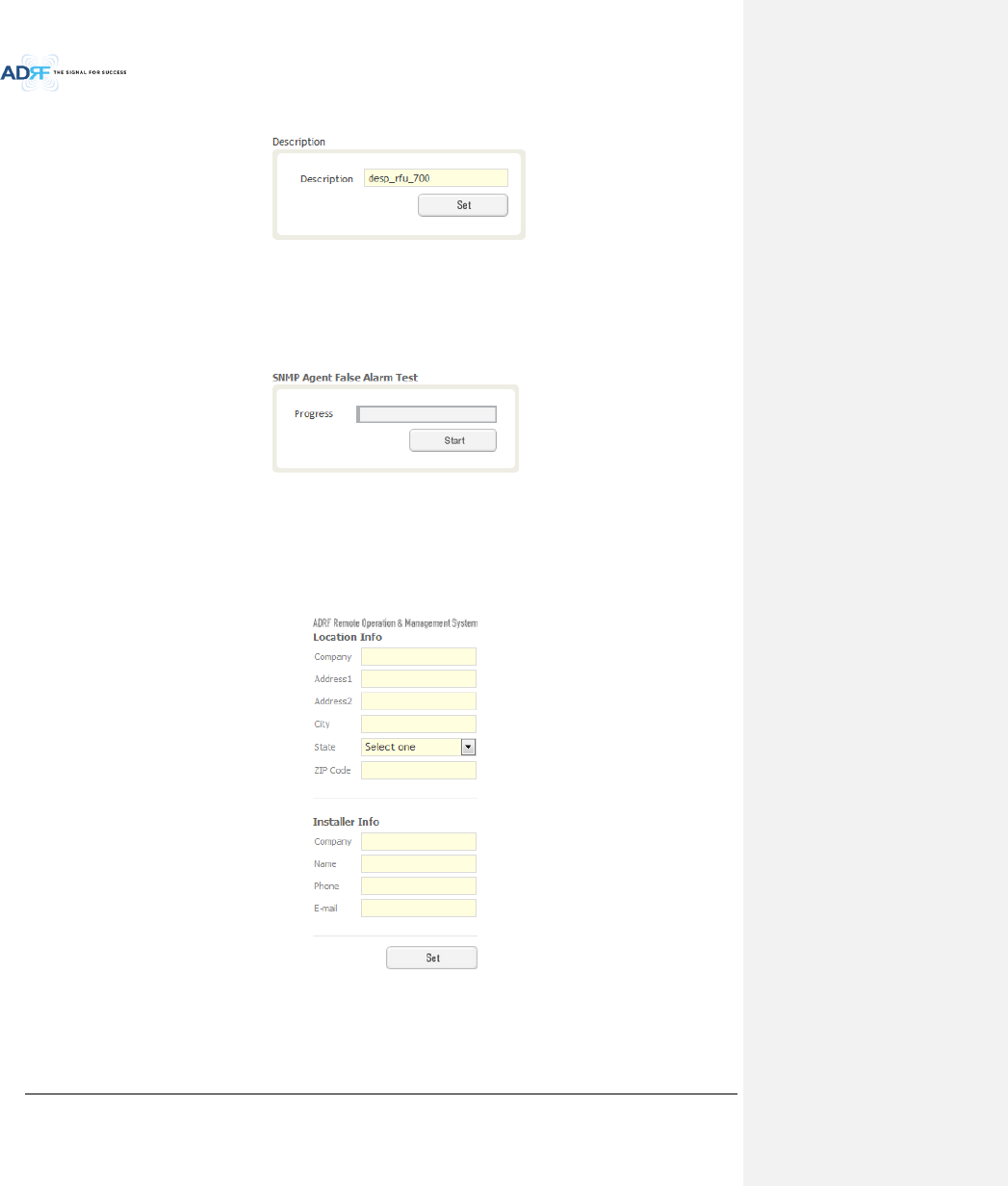
8.2.4.1.5 Description
Advanced RF Technologies, Inc.
95
This section allows the user to save the description of NMS.
Figure 8-65 Description (Install – NMS)
8.2.4.1.6 SNMP Agent False Alarm Test
This section allows the user to generate both soft and hard fail alarms. After alarms are generated, the NOC
can poll the ADX to see if alarms are present. All alarms generated during this test are false alarms.
Figure 8-66 SNMP Agent False Alarm Test (Install – NMS)
8.2.4.1.7 Location Info / Installer Info
This section allows the user to specify the address of the repeater and also the information of the installer.
Figure 8-67 Location Info / Installer Info (Install – NMS)
Advanced RF Technologies, Inc.
96
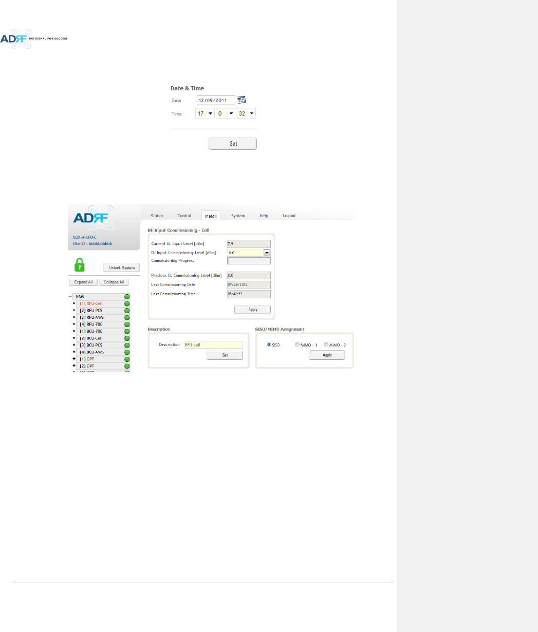
8.2.4.1.8 Date & Time
This section allows the user to specify the current date and time.
Figure 8-68 Date & Time Setting (Install – NMS)
8.2.4.2 Install – RFU
Figure 8-69 Install - RFU
Advanced RF Technologies, Inc.
97
8.2.4.2.1 RFU Commissioning
This section allows the user to perform RFU commission. To perform RFU commissioning, select a DL Input
Commissioning Level from the dropdown menu and click Apply. The commissioning progress is displayed on the
Commissioning Progress bar. Any errors, warnings, and messages will appear via a popup window. Please refer to
the ADX Installation Guide to determine the proper RFU commissioning levels.
Figure 8-70 RFU Commissioning (Install – RFU)
8.2.4.2.2 Description
This section allows the user to set the description of RFU.
Figure 8-71 Description (Install – RFU)
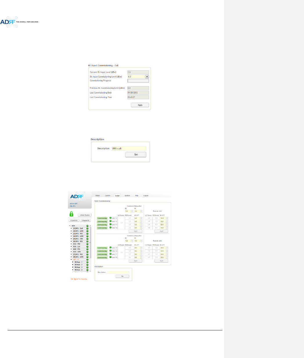
8.2.4.3 Install – OPT
Figure 8-72 Install – OPT
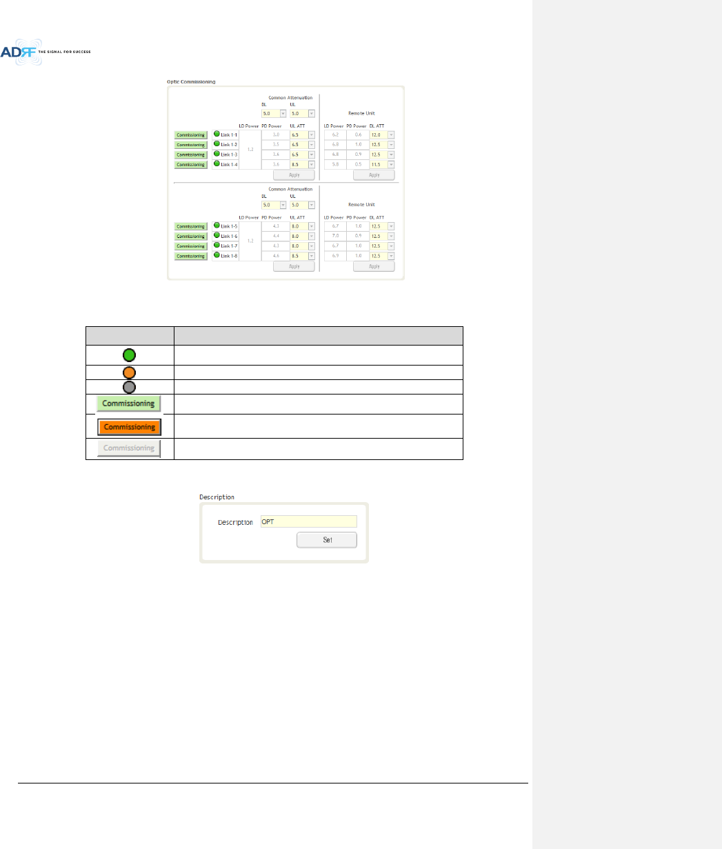
8.2.4.3.1 Optic Commissioning
This section will allow the user to perform any optic compensation if it is necessary. The Commissioning
button will turn orange if optic compensation is needed.
Advanced RF Technologies, Inc.
98
Figure 8-73 Optic control (Control – OPT)
Table 8-22 Description for Optic control (Control – OPT)
Display & Control
Description
Optic loss is less than 5dBo
Optic loss is more than 5dBo
Not connected to a RU
No optic loss compensation is needed.
Optic loss compensation is needed.
Not connected to a RU
8.2.4.3.2 Description
This section allows the user to save the description of OPT.
Figure 8-74 Description (Install – OPT)
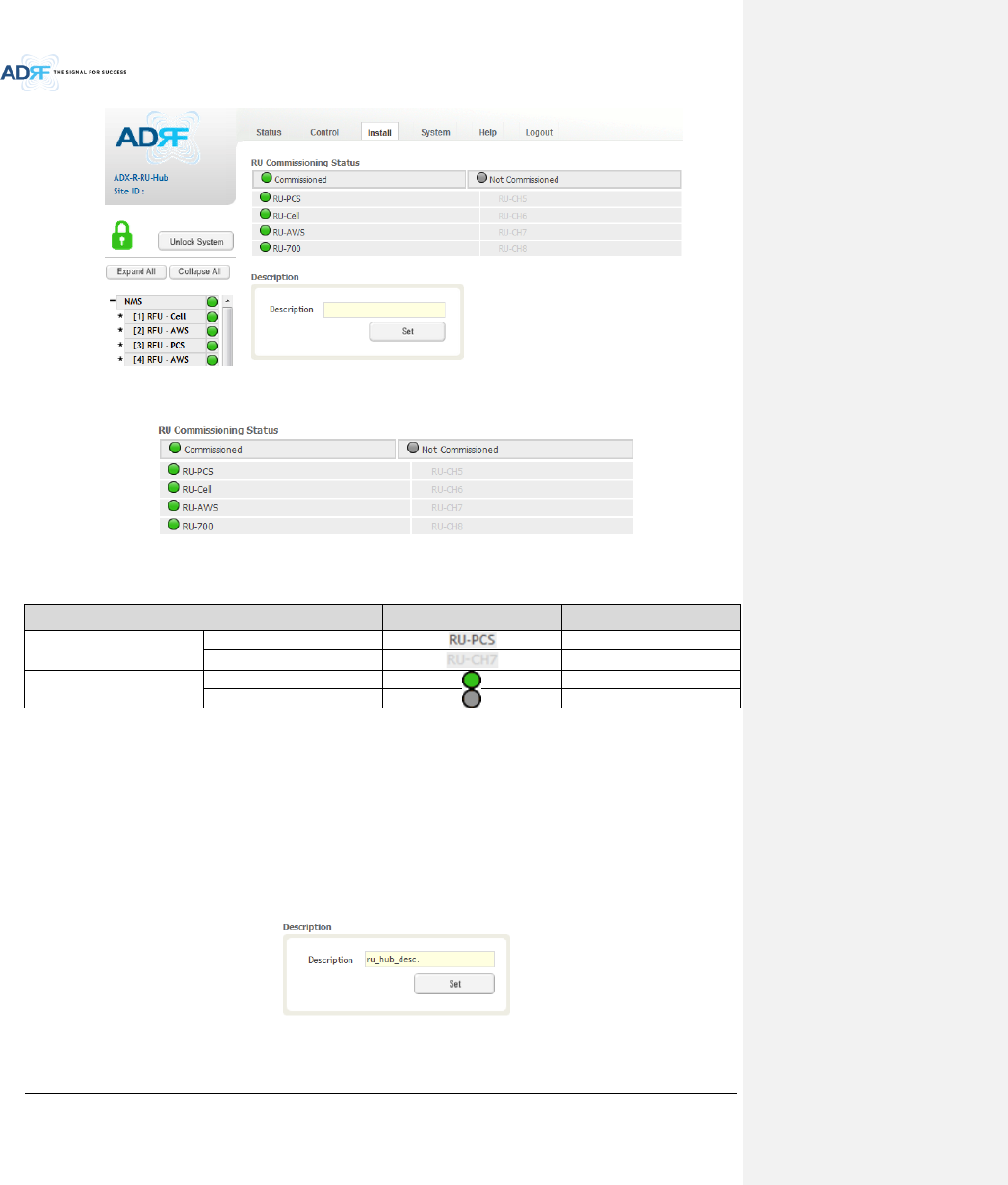
8.2.4.4 Install – RU Hub
Advanced RF Technologies, Inc.
99
Figure 8-75 Install-RU Hub
8.2.4.4.1 RU Commissioning Status
Figure 8-76 RU Commissioning Status (Install-RU Hub)
Table 8-23 Description for RU Commissioning status
Status
Display
Description
Installed Status
Physically Installed
Text is black
Physically Not-Installed
Text is gray
Commissioning Status
Success
Green
Fail or not commissioned
Gray
8.2.4.4.2 Description
This section allows the user to save the description of RU Hub.
Figure 8-77 Description (Install-RU Hub)
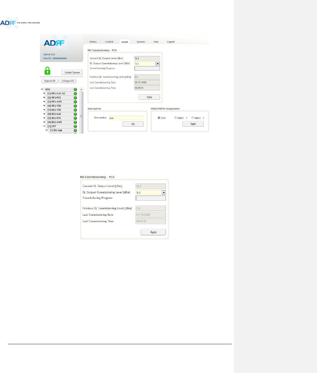
8.2.4.5 Install – Remote Module (Master or Slave RU)
Advanced RF Technologies, Inc.
100
Figure 8-78 Install-Remote Module
8.2.4.5.1 RU Output Commissioning
This section allows the user to perform RU commission. To perform RU commission, select a DL Output
Commissioning Level from the dropdown menu and then click Apply. The commissioning progress is displayed on
the Commissioning Progress bar. Any errors, warnings, and messages will appear via a popup window.
Figure 8-79 RU Output Commissioning (Install-RU)
Advanced RF Technologies, Inc.
101
8.2.4.5.2 Description
This section allows the user to save the description of remote module.
Figure 8-80 Description (Install-Remote Module)
8.2.5 System
The System tab allows the user to perform firmware updates, upload closeout packages, view any changes to
the system, backup existing configuration, and add/remove user accounts, and change the login credentials of the
Administrator.
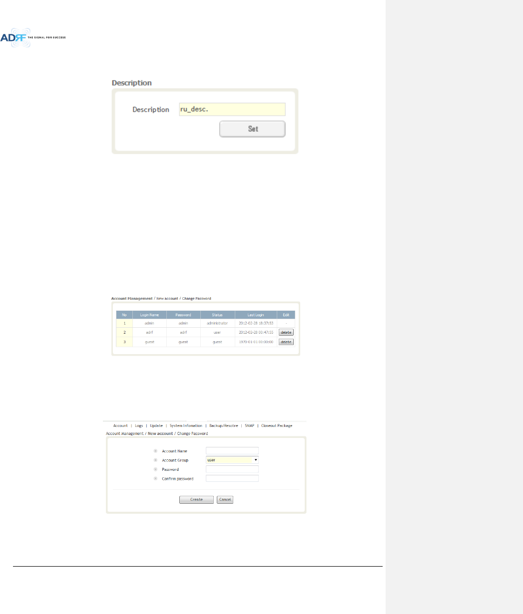
8.2.5.1 System: Account
8.2.5.1.1 System: Account - Account Management (Admin Only)
The Account Management section allows the Administrator to delete any user/guest account. Please note
that the Account Management section is only available if you are logged into the system as the Administrator. To
delete a user/guest account click on the Account Management link and under the Delete column, click on the
delete button.
Figure 8-81 Account Management
8.2.5.1.2 System: Account - New Account (Admin Only)
The New account section allows the Administrator to create a new user/guest account. Please note that the
new account section is only available if you are logged into the system as the Administrator. To create a new
user/guest account click on the new account link and fill in the fields highlighted in yellow as shown below.
Figure 8-82 New Account
Advanced RF Technologies, Inc.
102
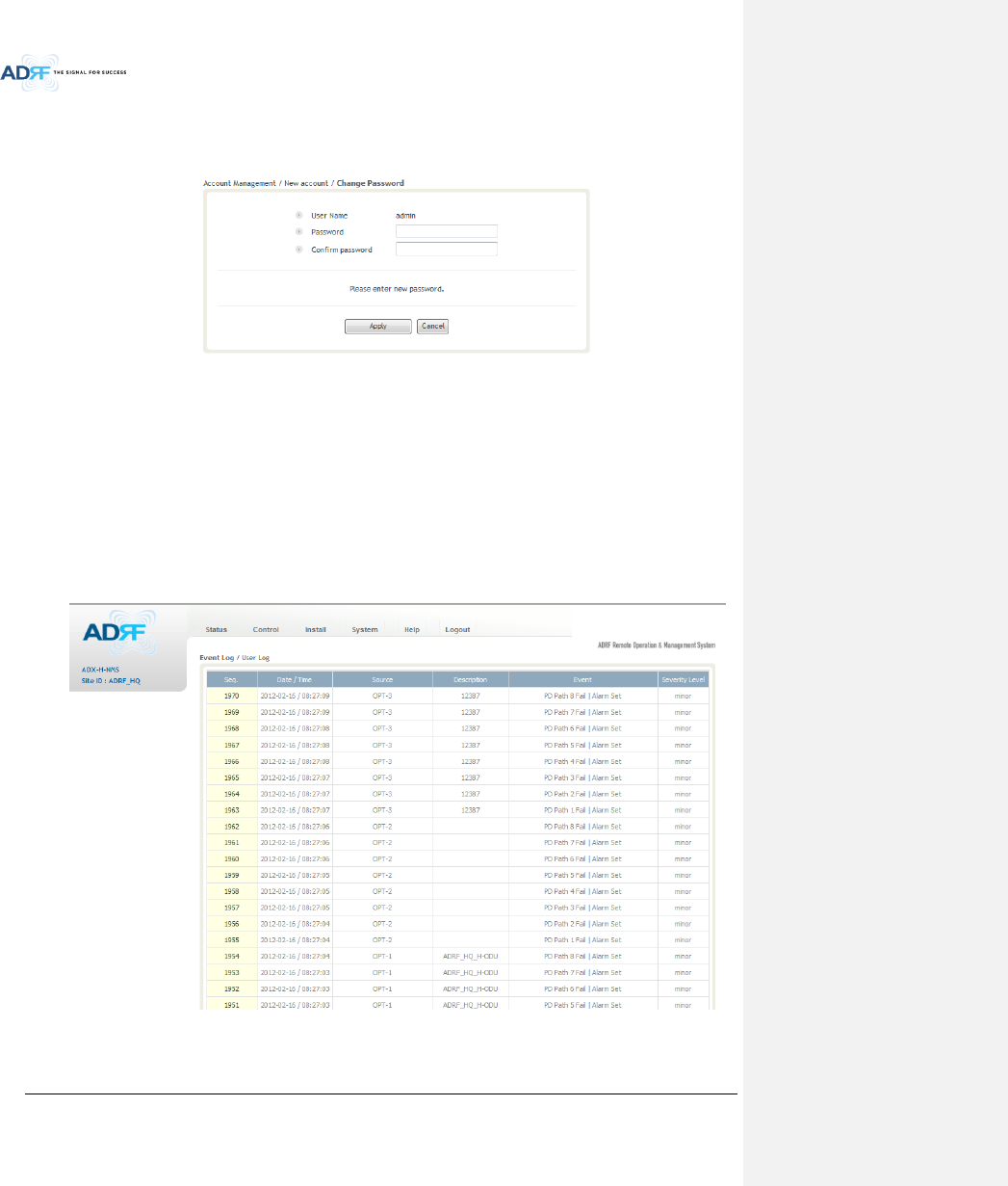
8.2.5.1.3 System: Account - Change Password
The Change Password section allows the current user who is logged into the system to change their login
credentials.
Figure 8-83 Change Password
8.2.5.2 System: Logs
8.2.5.2.1 System: Logs - Event Log
This section displays system events that have taken place. The Event Log displays who has made the changes,
the time and date of when the event took place, and what changes were made to the system. The System Log
tracks the following events:
System Initiation
Alarm Set
Alarm Clear
Figure 8-84 Event Log
Advanced RF Technologies, Inc.
103
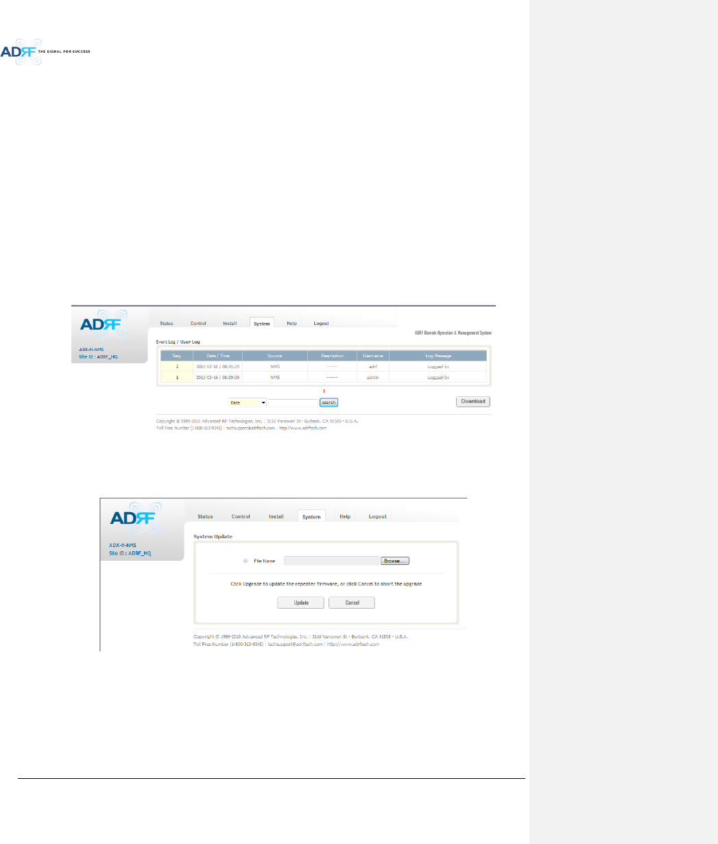
8.2.5.2.2 System: Logs - User Log
This section tracks user activity within the system. The User Log displays who has made the changes, the time
and date of when the event took place, and what changes were made to the system. The User Log tracks the
following items:
Log in / Log out activity
Changes to gain/attenuation/output values
System event generated by user(firmware update, backup/resote, create/delete account)
DAS Navigation Tree Lock/Unlock
Description change
Repeater/installer information change
Setting date/time
Figure 8-85 User Log
8.2.5.3 System: Update
To perform a firmware update, click on the System:Update tab and the following screen will show up.
Figure 8-86 System update
Click on the ‘Browse’ button and locate the firmware file.
Click on the Update button to perform the firmware update.
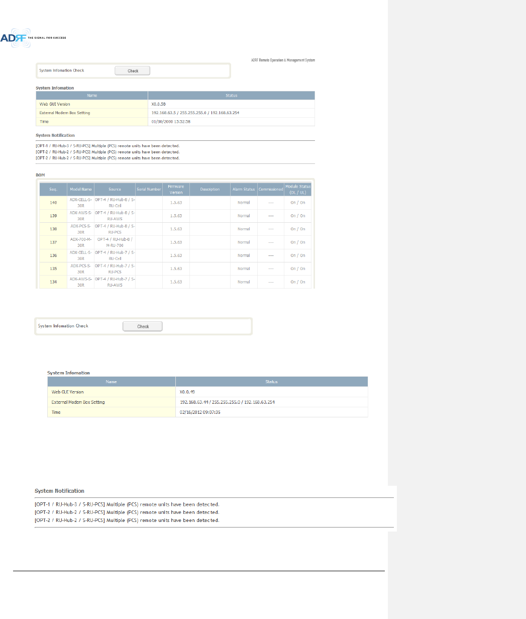
8.2.5.4 System: System Information
8.2.5.4.1 System: System Information
Advanced RF Technologies, Inc.
104
System Information Check
The System Information Check button will check the ADX configuation and report possible discrepancies.
System Information
This section displays the general system information of the ADX DAS.
Figure 8-87 System Information
System Notification
This section is displayed only when the following conditions are present:
- When multiple remote modules with same frequency band exist in a RU.
- When the remote module does not match with the RFU being used.
Figure 8-88 System Notification
BOM

Advanced RF Technologies, Inc.
105
BOM displays all parts that are connected to the ADX-H-NMS.
The BOM can be downloaded as a CSV file by clicking the ‘Download’ button at the bottom right.
Figure 8-89 Bill of material
Advanced RF Technologies, Inc.
106
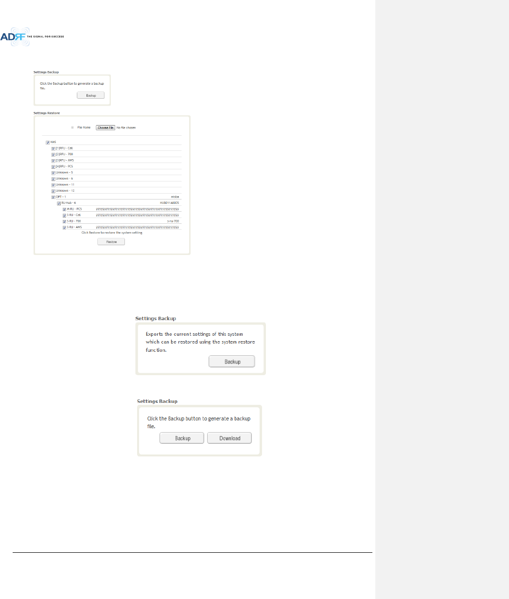
8.2.5.5 System: Backup/Restore
Settings Backup
Clicking the Backup will create a temporary backup file stored inside of the ADX. Once the file is created, it will
need to be downloaded to a computer. A download button will appear after the backup file has been created. If
the ADX is power cycled or rebooted, then the temporary backup file will be lost. We recommend downloading
the backup file immediately after it has been created. Click on the Download button to download the backup file.
Figure 8-90 Setting Backup (Before)
Figure 8-91 Setting Backup (After)
Advanced RF Technologies, Inc.
107
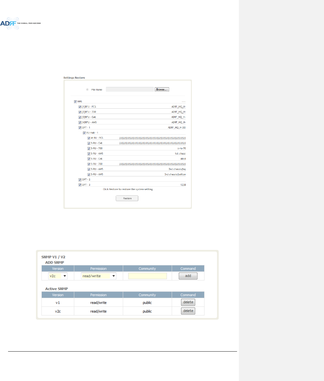
Setting Restore
Restore function can be used to restore the saved settings from the backup file. Once the backup file is loaded,
the tree in the figure below will appear. Check the boxes of the modules that you would like to restore and then
click the “Restore” button at the bottom on this section.
We recommend creating a new backup file if adding or removing modules from the ADX. Discrepancies
between the backup file and the existing tree could cause restore errors.
Figure 8-92 Setting Restore
8.2.5.6 System: SNMP
SNMP V1/V2
This section allows you to add community strings for SNMP v1 and v2.
Figure 8-93 SNMP V1/V2
Advanced RF Technologies, Inc.
108
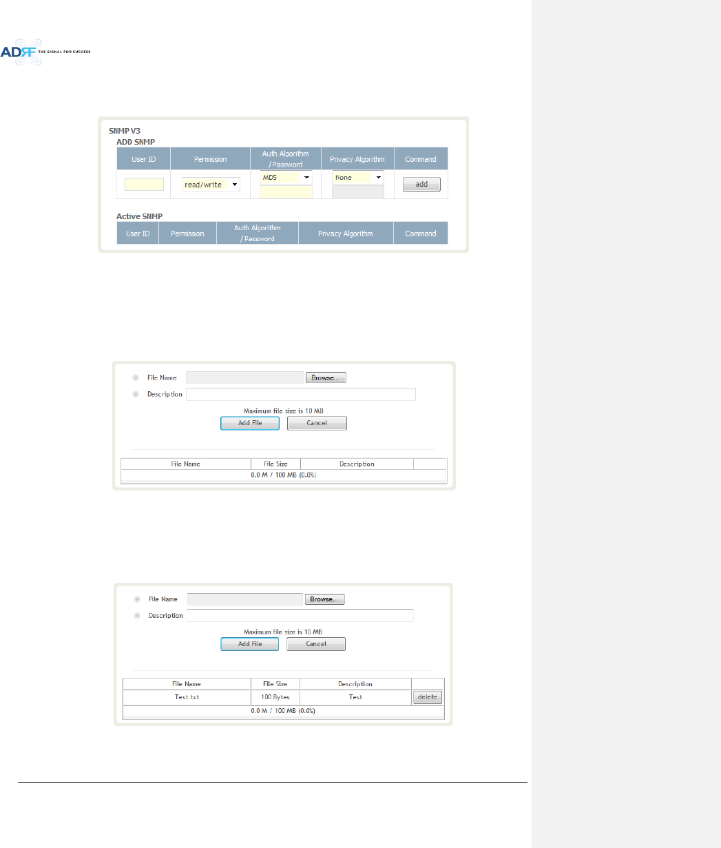
SNMP V3
This section allows the user to add accounts for SNMP v3.
Figure 8-94 SNMP V3
8.2.5.7 System: Closeout Package
The closeout package section will allow the user to upload documents to the ADX-H-NMS. The maximum file
size for each upload is limited to 10 MB. The total amount of space available for uploading document is 100 MB.
Please do not use this section as the primary storage location of your documents. Documents may become
unavailable if the system goes down.
Figure 8-95 System- Closeout Package
To upload documents to the module, click on the “Browse” button and locate the file that you would like to
upload, then enter in a Description of the file being uploaded. Afterwards, click on the “Add File” button to upload
the file. Below is what you will see after the file upload. To delete the file, click on the delete button located in the
last column.
Figure 8-96 System- Closeout Package after the file upload

Advanced RF Technologies, Inc.
109
8.2.6 Help
If an internet connection is available, clicking on the Help Tab will redirect the user to our Technical Support
page.
Figure 8-97 Help
8.2.7 Logout
Clicking the Logout button will log the current user off the system.
8.3 Guest Mode
When logging into the system as a guest, the guest will only have read-only privileges and will not be able to
make any changes to the system.
Advanced RF Technologies, Inc.
110
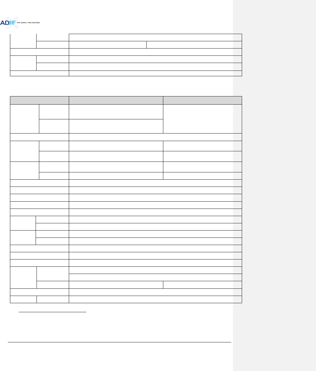
9. SYSTEM SPECIFICATION
9.1 Specification for PS78, SMR
Parameters
PS78
SMR
Frequency
Downlink
P7
758-775MHz
S8
851-869MHz
S9
929-930MHz
935-940MHz
Uplink
P7
788-805MHz
S8
806-824MHz
S9
896-901MHz
Input Power Range
0~+25dBm
Gain
Downlink
5~30dB, 0.5dB step, ATT range: 0~25dB
Uplink
-5~30dB, 0.5dB step, ATT range: 0~35dB
Maximum
Output
Power1
Downlink at
RU
30dBm±2dB
Uplink at HE
-15dBm±2dB
Noise Figure
< 10dB@maximum gain
VSWR
< 1:1.5
Optical Loss
0~5dBo
System Delay
< 2us
Spurious
Meet FCC rules, 3GPP TS 36.104, 3GPP2 C.S0010-C
Nominal
Band/BW
for Industry
Canada
Downlink
P7
749-781 MHz
S8
840-880MHz
S9
925-949MHz
Uplink
P7
782-831 MHz
S8
811-834MHz
S9
887-911MHz
Dimension
(WXDXH)
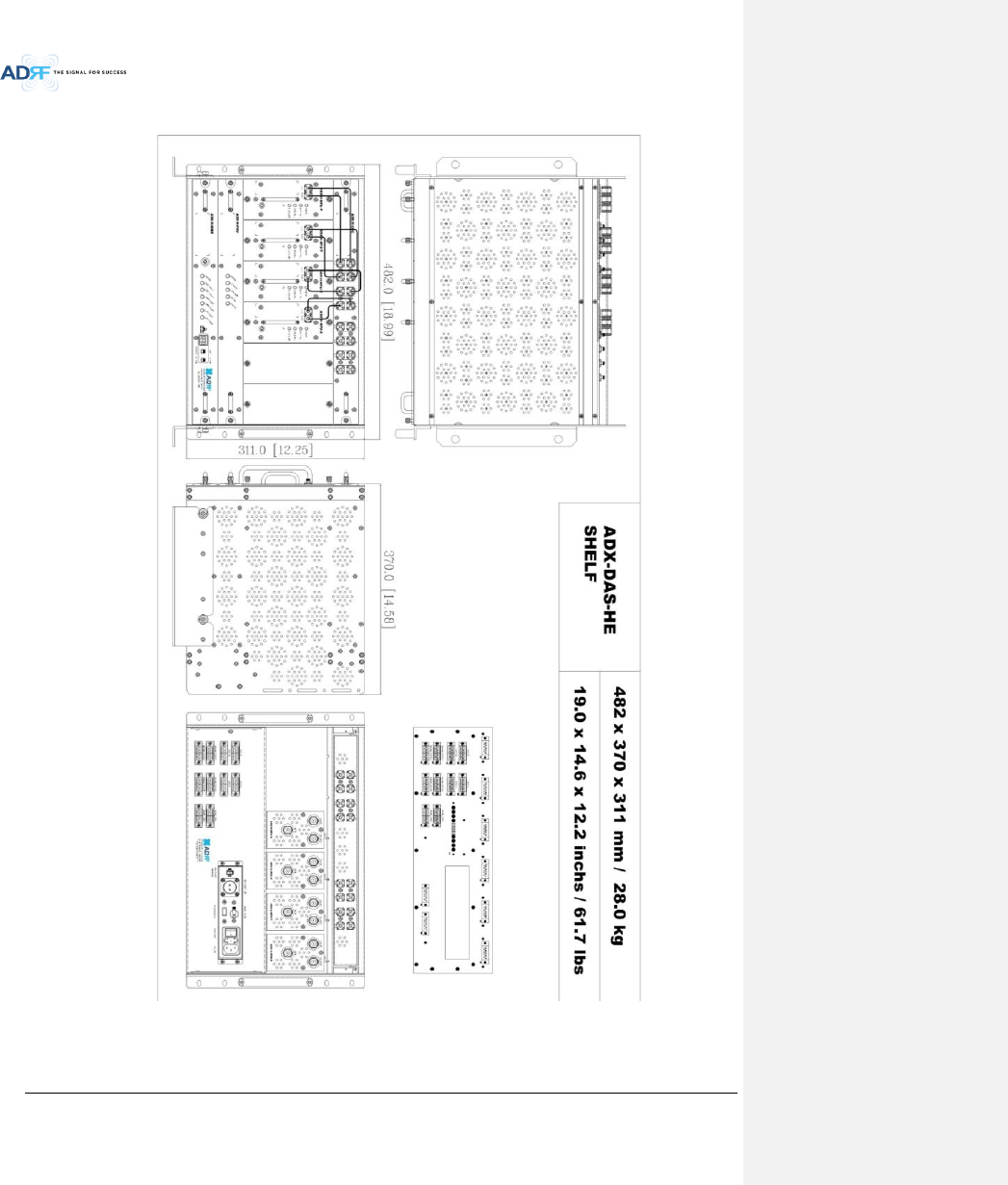
Head-End Shelf
19.0 x 14.6 x 12.2 inches (482 x 370 x 311 mm)
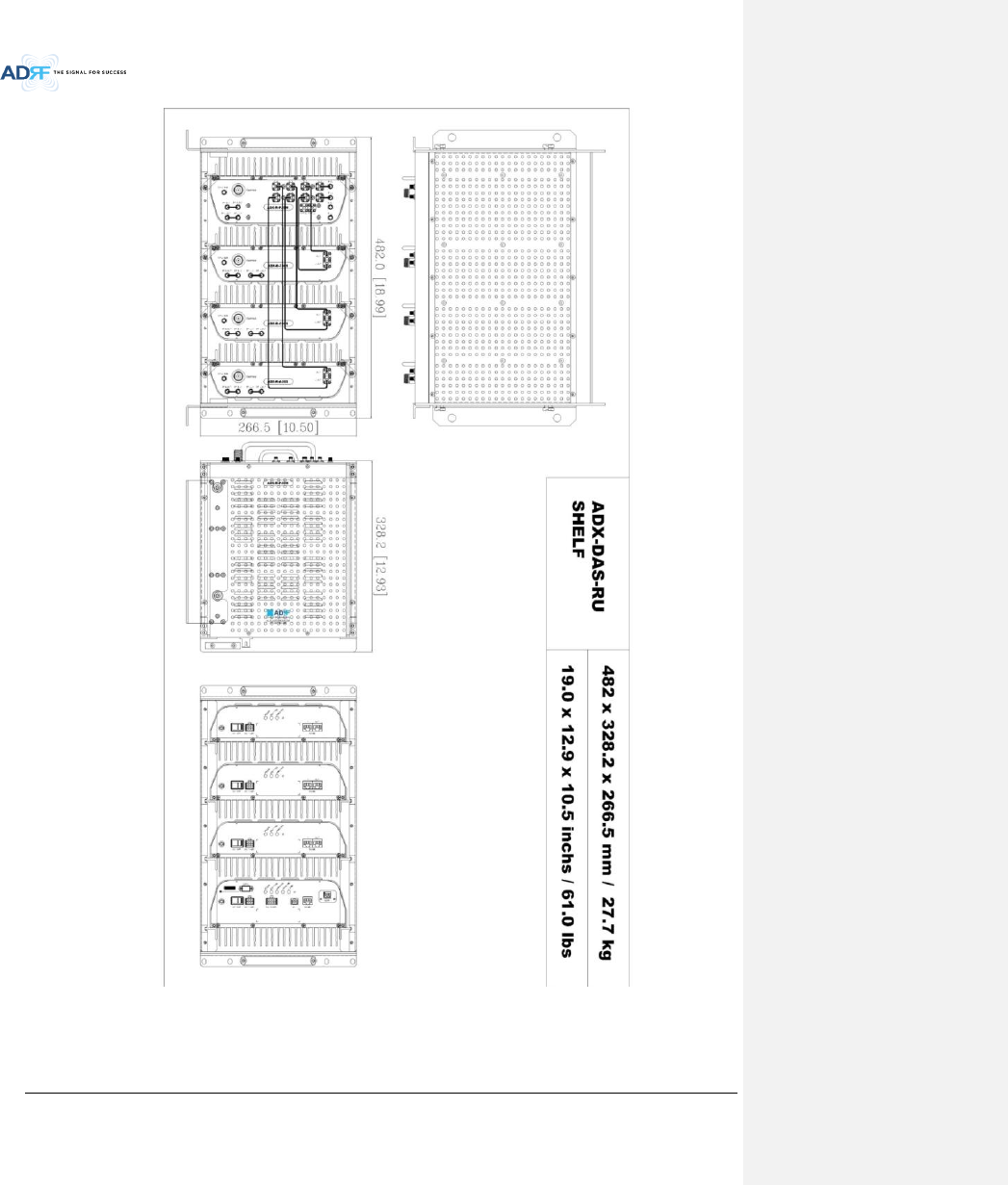
Remote-Unit
Shelf
19.0 x 12.9 x 10.5 inches (482 x 328.2 x 266.5 mm)
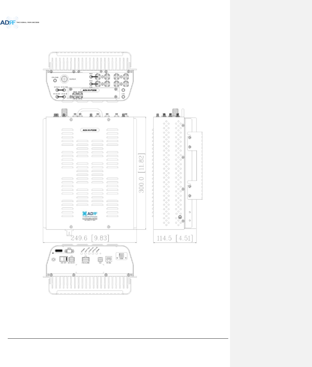
Master RU
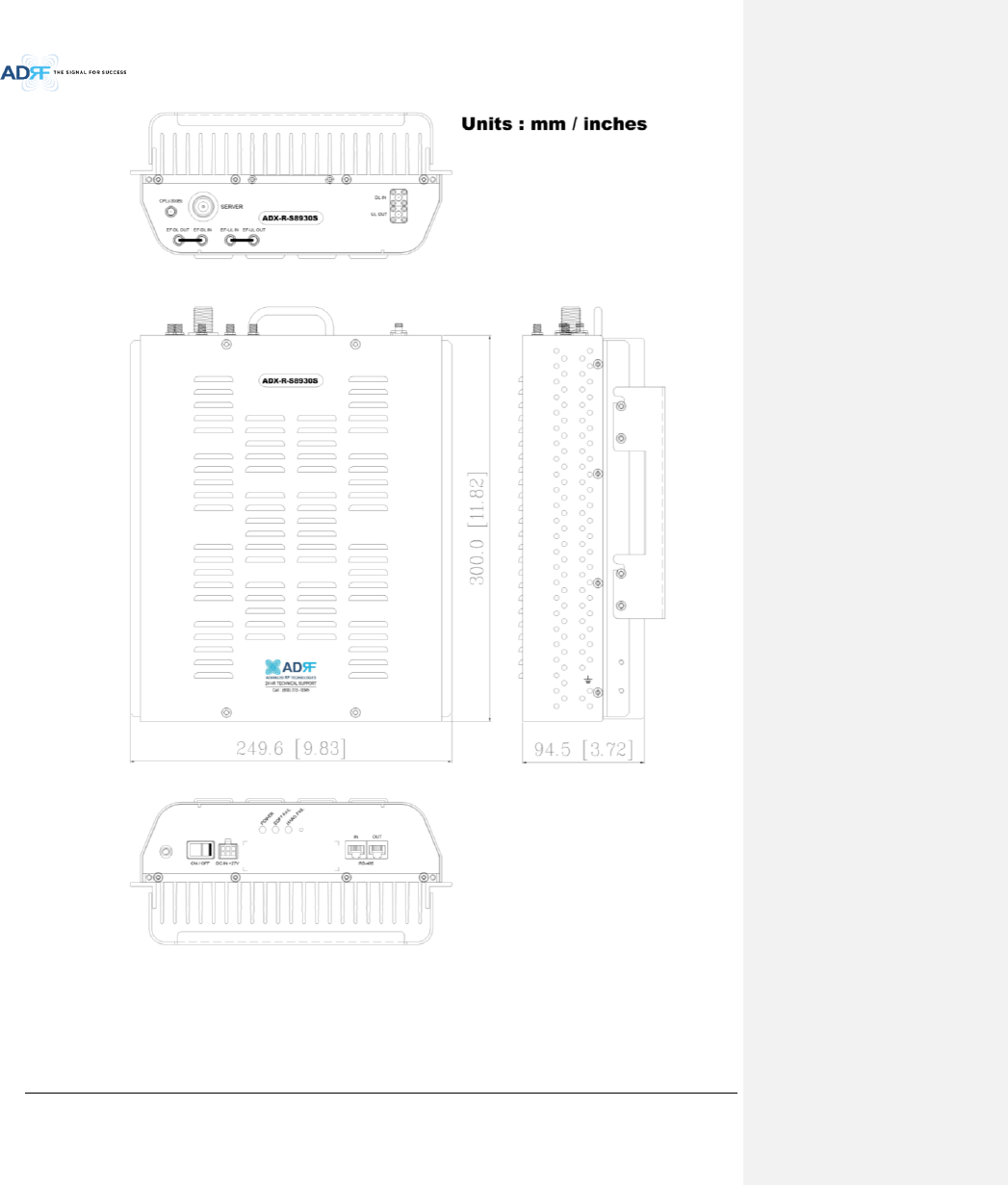
11.8 x 9.8 x 4.5 inches (300 x 249.6 x 114.5 mm)
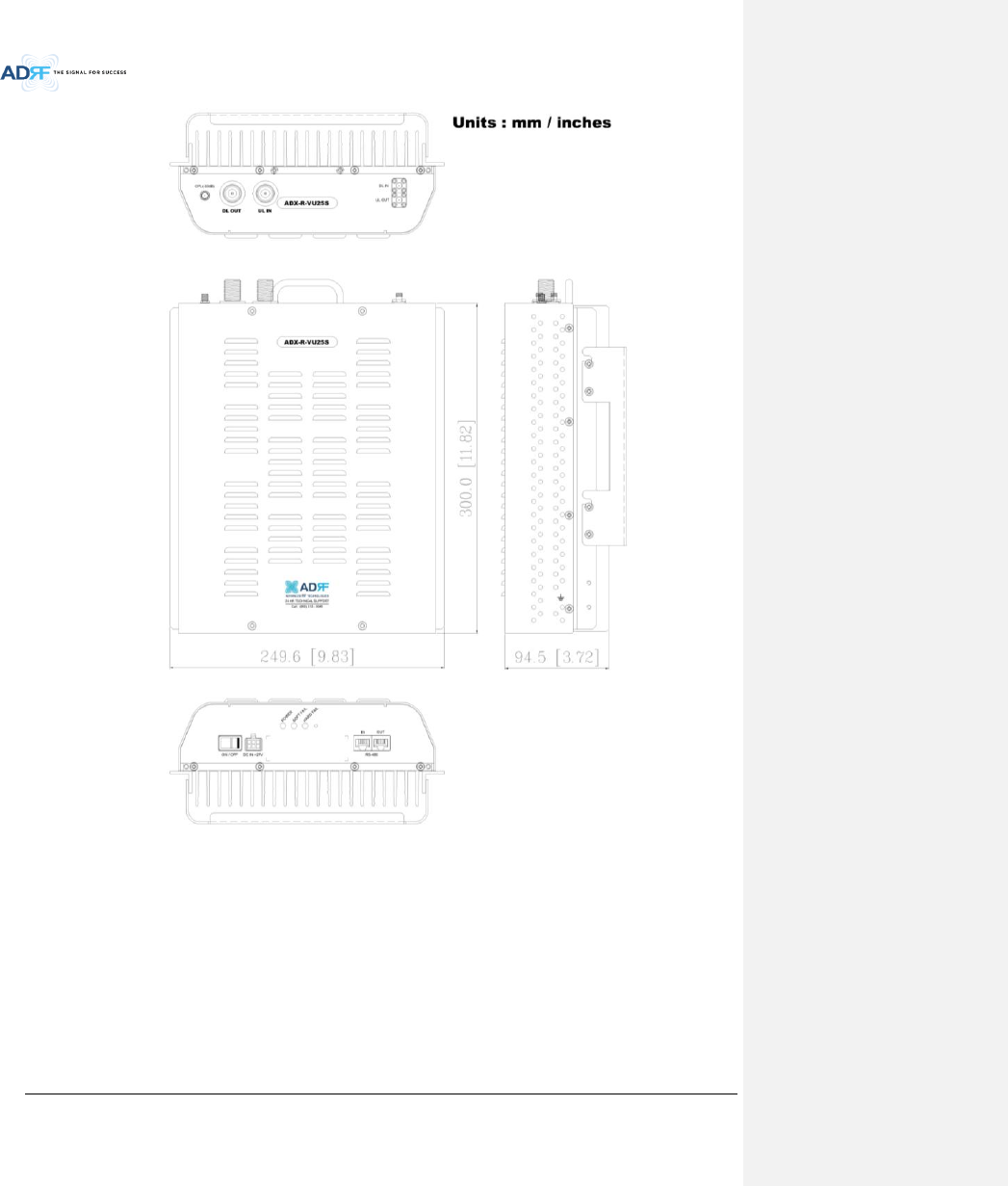
Slave RU
11.8 x 9.8 x 3.7 inches (300 x 249.6 x 94.5 mm)
Weight
Head-End Shelf
83.7 lbs (38.0 Kg) @4 RFU, CHC-H, PSU and NMS
Remote-Unit
Shelf
61.0 lbs (27.7 kg) @ 1 master RU, 3 Slave RU
Master RU
13.2 lbs (6.0 kg)
Slave RU
11.7 lbs (5.3 kg)
Operating Temperature
14-122F(-10-50°C)
Operating Humidity
5~90%RH
Power Input
110/220V, 50-60Hz, 24V or -48V DC(optional)
Power
Head-End
52W@4 RFU, 1 ODU Rack with 2 ODUs and NMS
1 The Manufacturer's rated output power of this equipment is for single carrier operation. For situations when
multiple carrier signals are present, the rating would have to be reduced by 3.5 dB, especially where the output
signal is re-radiated and can cause interference to adjacent band users. This power reduction is to be by means of
input power or gain reduction and not by an attenuator at the output of the device
메모 [H5]: 주파수 범위 수정 15/05/19
메모 [Y6]: 실제로 측정하셔서
기입요청합니다.
15/02/03
Advanced RF Technologies, Inc.
111
consumptio
n
28W@1 RFU, , 1 ODU Rack with 2 ODUs and NMS
Remote-Unit
60W
53W
Network Management System
Ethernet(RJ45)
RF
connector
Head-End
N-type(Female)
Remote-Unit
N-type(Female)
Input/output Impedance
50
9.2 Specification for VU, BT
Parameters
BT
TBD
Frequency
Downlink
2496-2690MHz
(BRS TDD)
Uplink
2496-2690MHz
(BRS TDD)
Input Power Range
-15~+37dBm
Gain
Downlink
0~52dB, 0.5dB step,
ATT range: 0~52dB
Uplink
-5~30dB, 0.5dB step,
ATT range: 0~35dB
Maximum
Output
Power2
Downlink at
RU
37dBm±2dB
Uplink at HE
-15dBm±2dB
Noise Figure
< 10dB@maximum gain
VSWR
< 1:1.5
Optical Loss
0~5dBo
System Delay
< 2us
Spurious
Meet FCC rules, 3GPP TS 36.104, 3GPP2 C.S0010-C
Dimension
(WXDXH)
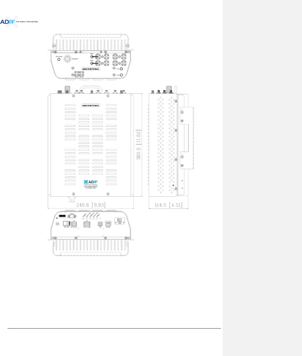
Master RU
11.8 x 9.8 x 4.5 inches (300 x 249.6 x 114.5 mm)
Slave RU
11.8 x 9.8 x 3.7 inches (300 x 249.6 x 94.5 mm)
Weight
Master RU
13.2 lbs (6.0 kg)
Slave RU
11.7 lbs (5.3 kg)
Operating Temperature
14-122F(-10-50°C)
Operating Humidity
5~90%RH
Power Input
110/220V, 50-60Hz, 24V or -48V DC(optional)
Power
consumptio
n
Head-End
52W@4 RFU, 1 ODU Rack with 2 ODUs and NMS
28W@1 RFU, 1 ODU Rack with 2 ODUs and NMS
Remote-Unit
87W
Network Management System
Ethernet(RJ45)
RF
Head-End
N-type(Female)
2 The Manufacturer's rated output power of this equipment is for single carrier operation. For situations when
multiple carrier signals are present, the rating would have to be reduced by 3.5 dB, especially where the output
signal is re-radiated and can cause interference to adjacent band users. This power reduction is to be by means of
input power or gain reduction and not by an attenuator at the output of the device
Advanced RF Technologies, Inc.
112
connector
Remote-Unit
N-type(Female)
Input/output Impedance
50
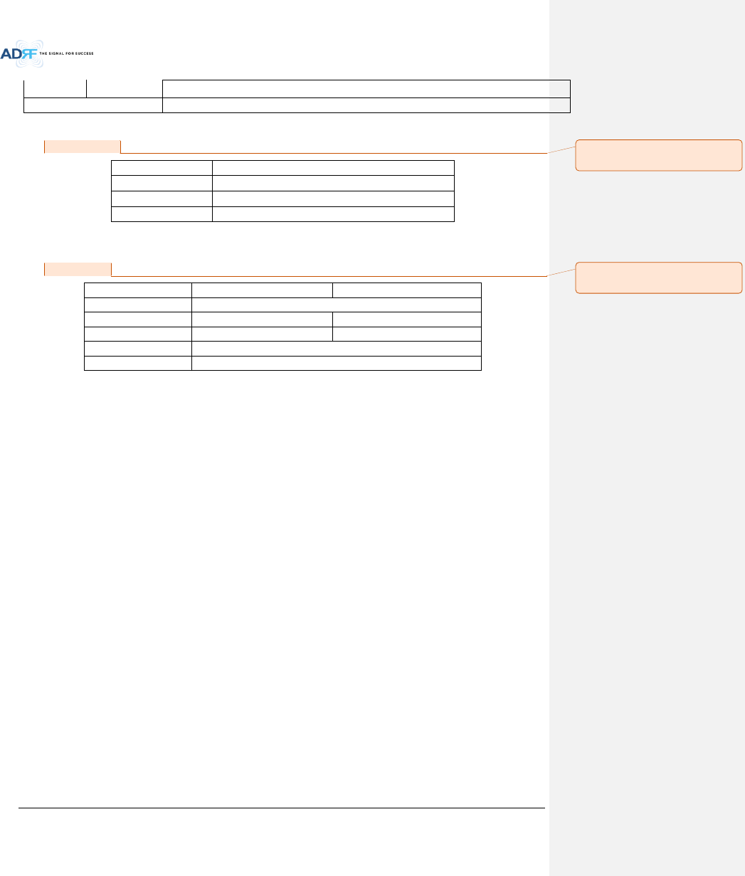
9.3 FCC Certification
Item
FCC Certification
ADX-R-SMR
Part 20, Part 90
ADX-R-78P
Part 90
ADX-R-BT
Part 20
10. ANTENNA SPECIFICATIONS
10.1 Omni Antenna
Frequency
698-960MHz
1710-2690MHz
Polarization
Vertical
Gain
2dBi
3dBi
VSWR
<1.7:1
<1.5:1
Impedance
50
Power Rating
50W
Note.
Please note that integrators, end-users or installers should not use the antenna with more gain than 3dBi(For
Model: ADX-R-BT), 2dBi (For Model: ADX-R-SMR, ADX-R-78P) to meet the RF exposure requirement.
Part 90.635 requirement
Antennas must be installed in accordance with FCC 90.635. With 2 dBi gain antennas the height of the antenna
above average terrain (HAAT) is permitted over 1372m. For different gain antennas refer to the relevant rules.
Part 90.219 requirement
The radiated power must be limited to 1W. Therefore, this device meet the 90.219 (e)(1) 5W ERP limitation
requirement.
Prior to equipment use the service must be registered with the FCC. This can be done through the FCC’s website at
https://signalboosters.fcc.gov/signal-boosters
메모 [Y7]: FCC part 명기
15/02/03
메모 [Y8]: 안테나 규격 추가
15/02/03
Advanced RF Technologies, Inc.
113
11. MECHANICAL DRAWING
Figure 11-1 HE Drawing
Advanced RF Technologies, Inc.
114
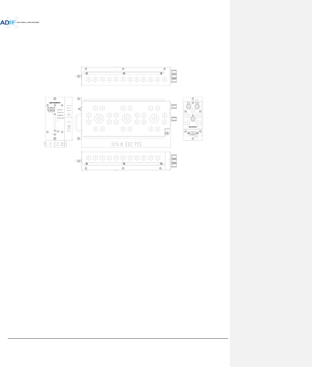
Figure 11-2 RFU Drawing for SMR/PS
Advanced RF Technologies, Inc.
115
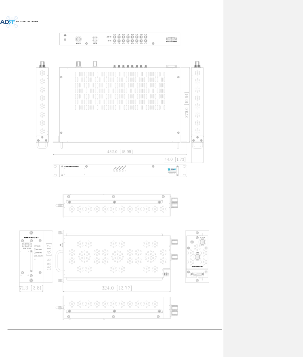
Figure 11-3 RFU Drawing for VU
Advanced RF Technologies, Inc.
116
Figure 11-4 RFU Drawing for BT
Figure 11-5 Master RU Drawing for PS
Advanced RF Technologies, Inc.
117
Figure 11-6 Master RU Drawing for BT
Advanced RF Technologies, Inc.
118
Figure 11-7 Slave RU Drawing for SMR
Advanced RF Technologies, Inc.
119
Figure 11-8 Slave RU Drawing for VU
Advanced RF Technologies, Inc.
120
Figure 11-9 RU Rack Shelf Drawing