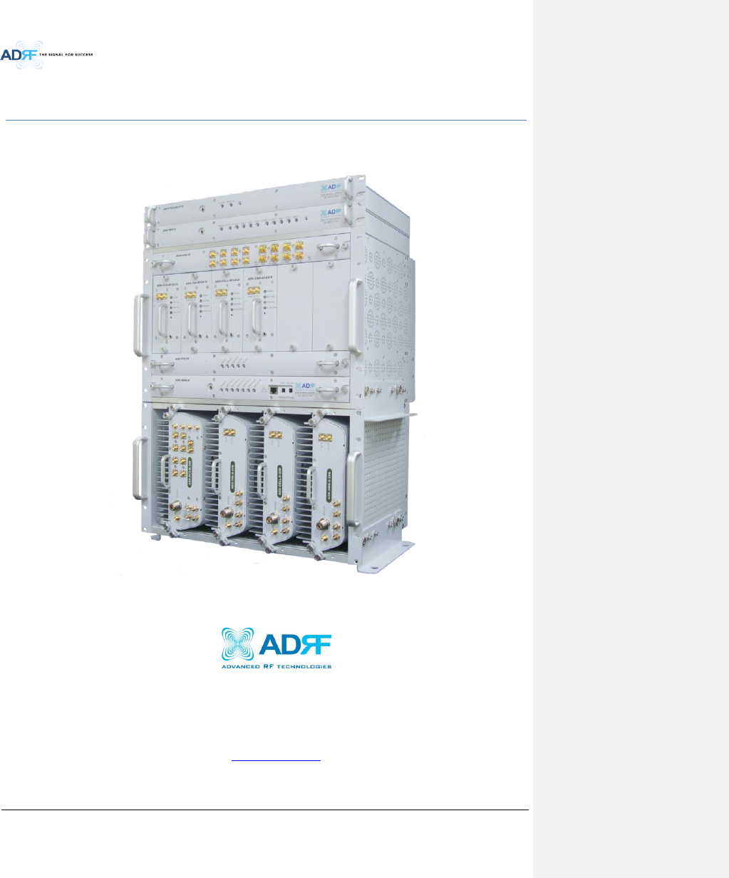
ADRF KOREA ADX-R-SMR DAS (Distributed Antenna System) User Manual ADX DAS
ADRF KOREA, Inc. DAS (Distributed Antenna System) ADX DAS
Contents
- 1. User Manual_Installaion Manual rev Part1
- 2. User Manual_Installaion Manual rev Part2
- 3. User Manual_Installaion Manual rev Part3
User Manual_Installaion Manual rev Part1

Advanced RF Technologies, Inc.
ii
Information in this document is subject to change without notice.
Advanced RF Technologies, Inc. 1996-2013.
All rights reserved.
Please send comments to:
E-Mail: info@adrftech.com
Phone: (818) 840-8131
(800) 313-9345
Fax: (818) 840-8138
Address:
Advanced RF Technologies, Inc.
Attention: Technical Publications Department
3116 Vanowen St.
Burbank, CA 91505
USA
www.adrftech.com
Advanced RF Technologies, Inc.
iii
Revision History
Change List
Version
Change list
Contents
Version
Author
Descriptions
Date

Advanced RF Technologies, Inc.
iv
Table of Contents
1. Introduction ...................................................................................................................................................... 14
1.1 Highlights ................................................................................................................................................... 14
1.2 ADX DAS Quick View .................................................................................................................................. 15
1.2.1 HE Quick View .................................................................................................................................... 15
1.2.2 15
1.2.3 RU Quick View .................................................................................................................................... 16
1.3 Warnings and Hazards ............................................................................................................................... 17
2. Block Diagram ................................................................................................................................................... 21
2.1 ADX DAS Block Diagram ............................................................................................................................. 21
2.2 ADX DAS Topology ..................................................................................................................................... 22
2.3 SISO Configuration ..................................................................................................................................... 23
2.4 ADX-DAS Scalability ................................................................................................................................... 24
3. ADX Overview ................................................................................................................................................... 25
3.1 Head End .................................................................................................................................................... 25
3.1.1 NMS (Network Management System) ................................................................................................ 26
3.1.1.1 LEDs .......................................................................................................................................... 26
3.1.1.2 Ethernet Port ............................................................................................................................ 27
3.1.1.3 Host/Remote Switch ................................................................................................................. 27
3.1.1.4 HE View/RU View Switch .......................................................................................................... 27
3.1.2 RFU (ADX-H-RFU-x) ............................................................................................................................. 28
3.1.2.1 LEDs .......................................................................................................................................... 29
3.1.2.2 RF Ports ..................................................................................................................................... 29
3.1.2.3 Communication Port ................................................................................................................. 29
3.1.3 Channel Combiner (ADX-H-CHC) ........................................................................................................ 29
3.1.3.1 RF ports ..................................................................................................................................... 30
3.1.3.2 RF ports ..................................................................................................................................... 30
3.1.4 Optic Distribution Unit (ADX-H-ODU + ADX-RACK-ODU).................................................................... 30
3.1.4.1 LEDs .......................................................................................................................................... 31
3.1.4.2 RF Ports ..................................................................................................................................... 31
3.2 Remote Unit ............................................................................................................................................... 32
3.2.1 ADX-R-x3xM (Master RU) ................................................................................................................... 33
3.2.1.1 LEDs .......................................................................................................................................... 33
3.2.1.2 RF Ports ..................................................................................................................................... 34
3.2.1.3 Optic Port .................................................................................................................................. 35
3.2.1.4 Power On/Off Switch & DC IN Port ........................................................................................... 35
3.2.1.5 PSU Alarm Port ......................................................................................................................... 35
3.2.1.6 GUI Port .................................................................................................................................... 35

Advanced RF Technologies, Inc.
v
3.2.1.7 RS-485 Port ............................................................................................................................... 35
3.2.1.8 ADDR ......................................................................................................................................... 36
3.2.2 ADX-R-xxxS/ADX-R-BTxxS/ADX-R-VU25S (Slave RU) .......................................................................... 37
3.2.2.1 LEDs .......................................................................................................................................... 37
3.2.2.2 RF Ports ..................................................................................................................................... 38
3.2.2.3 Power On/Off Switch & DC IN Port ........................................................................................... 39
3.2.2.4 RS-485 Port ............................................................................................................................... 39
3.2.3 RU Power Supply Options ................................................................................................................... 39
3.2.3.1 ADX-R-ADP (RU Power Adapter) ............................................................................................... 39
3.2.3.2 ADX-R-PSU (RU Power Supply Unit).......................................................................................... 39
4. Cable Connection .............................................................................................................................................. 41
4.1 Head End Connection Diagrams ................................................................................................................ 42
4.1.1 Front/Rear Head End Connection View with Optional BCU unit ........................................................ 42
4.1.2 Rear Head End Connection View with (4) OPT-8 units ....................................................................... 43
4.2 Remote Unit Connection Diagrams ........................................................................................................... 44
4.3 Remote Unit w/ 4-Way Combiner (ADX-R-4WS) ....................................................................................... 45
5. Mounting method ............................................................................................................................................. 46
5.1 Head End .................................................................................................................................................... 46
5.1.1 Rack Mount ........................................................................................................................................ 46
5.1.2 Wall Mount ......................................................................................................................................... 47
5.2 Remote Unit ............................................................................................................................................... 48
5.2.1 Rack Mount ........................................................................................................................................ 48
5.2.2 Wall Mount ......................................................................................................................................... 49
5.2.2.1 Remote Unit using RU Chassis (ADX-R-CHA-30) ....................................................................... 49
5.2.2.2 Individual Remote Module ....................................................................................................... 49
6. Installation ........................................................................................................................................................ 50
6.1 Pre-Installation Inspection ......................................................................................................................... 50
6.2 ADX DAS Installation Procedure ................................................................................................................ 50
6.2.1 HE Installation Procedure ................................................................................................................... 50
6.2.1.1 Installing a ADX DAS HE in a rack .............................................................................................. 50
6.2.1.2 Wall mounting the ADX DAS HE................................................................................................ 52
6.2.2 RU Installation Procedure ................................................................................................................... 54
6.2.2.1 Installing a ADX DAS RU in a rack .............................................................................................. 54
6.2.2.2 Wall mounting the ADX DAS RU ............................................................................................... 56
6.2.2.3 Wall mounting an ADX Remote Module ................................................................................... 58
6.2.3 ADX-H-OEU Installation Procedure .................................................................................................... 59
6.2.3.1 Installing a ADX-H-OEU in a Rack .............................................................................................. 59
6.2.3.2 Wall mounting the ADX-H-OEU ................................................................................................ 61
6.3 Grounding .................................................................................................................................................. 62

Advanced RF Technologies, Inc.
vi
6.4 Optic Port Cleaning .................................................................................................................................... 63
7. Warranty and Repair Policy .............................................................................................................................. 64
7.1 General Warranty ...................................................................................................................................... 64
7.2 Limitations of Warranty ............................................................................................................................. 64
7.3 Limitation of Damages ............................................................................................................................... 64
7.4 No Consequential Damages ....................................................................................................................... 64
7.5 Additional Limitation on Warranty ............................................................................................................ 64
7.6 Return Material Authorization (RMA) ....................................................................................................... 64
8. Web-GUI ........................................................................................................................................................... 65
8.1 Web-GUI Setup .......................................................................................................................................... 65
8.1.1 DAS system/PC Connection Using Web-GUI ...................................................................................... 65
8.2 Administrator/User Mode ......................................................................................................................... 66
8.2.1 Common ............................................................................................................................................. 66
8.2.1.1 Navigation tree Lock/Unlock .................................................................................................... 66
8.2.1.2 Navigation Tree......................................................................................................................... 66
8.2.1.3 Power Status ............................................................................................................................. 67
8.2.1.4 Commissioning Status ............................................................................................................... 67
8.2.1.5 Information ............................................................................................................................... 67
8.2.2 Status Tab ........................................................................................................................................... 68
8.2.2.1 Status – NMS ............................................................................................................................ 68
8.2.2.2 Status – BCU ............................................................................................................................. 71
8.2.2.3 Status – RFU .............................................................................................................................. 73
8.2.2.4 Status – ODU ............................................................................................................................. 75
8.2.2.5 Status – RU Hub ........................................................................................................................ 78
8.2.2.6 Status – Remote module .......................................................................................................... 79
8.2.3 Control Tab ......................................................................................................................................... 82
8.2.3.1 Control – NMS .......................................................................................................................... 82
8.2.3.2 Control – BCU ........................................................................................................................... 83
8.2.3.3 Control – RFU ............................................................................................................................ 84
8.2.3.4 Control – ODU ........................................................................................................................... 88
8.2.3.5 Control – RH Hub ...................................................................................................................... 89
8.2.3.6 Control – Remote Module (Master or Slave RU) ...................................................................... 90
8.2.4 Install Tab ........................................................................................................................................... 93
8.2.4.1 Install – NMS ............................................................................................................................. 93
8.2.4.2 Install – RFU .............................................................................................................................. 96
8.2.4.3 Install – OPT .............................................................................................................................. 97
8.2.4.4 Install – RU Hub ........................................................................................................................ 98
8.2.4.5 Install – Remote Module (Master or Slave RU) ........................................................................ 99
8.2.5 System .............................................................................................................................................. 101

Advanced RF Technologies, Inc.
vii
8.2.5.1 System: Account ..................................................................................................................... 101
8.2.5.2 System: Logs ........................................................................................................................... 102
8.2.5.3 System: Update....................................................................................................................... 103
8.2.5.4 System: System Information ................................................................................................... 103
8.2.5.5 System: Backup/Restore ......................................................................................................... 106
8.2.5.6 System: SNMP ......................................................................................................................... 107
8.2.5.7 System: Closeout Package ...................................................................................................... 108
8.2.6 Help .................................................................................................................................................. 109
8.2.7 Logout ............................................................................................................................................... 109
8.3 Guest Mode ............................................................................................................................................. 109
9. System Specification ....................................................................................................................................... 110
9.1 Specification for PS78, SMR ..................................................................................................................... 110
9.2 Specification for VU, BT ........................................................................................................................... 111
9.3 FCC Certification ...................................................................................................................................... 112
10. Antenna Specifications ................................................................................................................................... 112
10.1 Omni Antenna .......................................................................................................................................... 112
11. Mechanical Drawing ....................................................................................................................................... 113

Advanced RF Technologies, Inc.
viii
Figures
Figure 1-1 ADX DAS HE Quick View ..................................................................................................................... 15
Figure 1-2 ADX DAS RU Quick View ..................................................................................................................... 16
Figure 2-1 ADX DAS Block Diagram ...................................................................................................................... 21
Figure 2-2 ADX DAS Topology .............................................................................................................................. 22
Figure 2-3 ADX DAS SISO Configuration ............................................................................................................... 23
Figure 3-1 Head End Front View .......................................................................................................................... 25
Figure 3-2 ADX-H-NMS Front View ...................................................................................................................... 26
Figure 3-3 NMS LED ............................................................................................................................................. 26
Figure 3-4 Ethernet Port ...................................................................................................................................... 27
Figure 3-5 Host/Remote Switch ........................................................................................................................... 27
Figure 3-6 HE View/RU View Switch .................................................................................................................... 27
Figure 3-7 RFU Front & Rear View (excluding BT and VU) ................................................................................... 28
Figure 3-8 RFU Front & Rear View for BT ............................................................................................................ 28
Figure 3-9 RFU Front & Rear View for VU ............................................................................................................ 28
Figure 3-10 RFU LED .............................................................................................................................................. 29
Figure 3-11 Communication Port (RFU) ................................................................................................................. 29
Figure 3-12 ADX-H-CHC Front & Rear View ........................................................................................................... 30
Figure 3-13 ADX-RACK-ODU + ADX-H-ODU-4/1 Front & Rear View ...................................................................... 31
Figure 3-14 ADX-H-OPT-8 LED ............................................................................................................................... 31
Figure 3-15 ODU RF Ports ...................................................................................................................................... 31
Figure 3-16 RU Front View ..................................................................................................................................... 32
Figure 3-17 RU Rear View ...................................................................................................................................... 32
Figure 3-18 Master RU Front & Rear View(excluding BT) ...................................................................................... 33
Figure 3-19 Master RU Front & Rear View only for BT .......................................................................................... 33
Figure 3-20 Master RU LED .................................................................................................................................... 33
Figure 3-21 RF Ports (Master RU) .......................................................................................................................... 34
Figure 3-22 Ports at the back panel (Master RU) .................................................................................................. 35
Figure 3-23 Correct RS-485 connection between Master RU and Slave RU or between Slave RUs ...................... 36
Figure 3-24 Wrong RS-485 connection between Master RU and Slave RU or between Slave RUs ....................... 36
Figure 3-25 Do NOT connect RS-485 ports of Remote Module to network equipment port ................................ 36
Figure 3-26 Slave RU Front & Rear View (excluding BT and VU) ........................................................................... 37
Figure 3-27 Slave RU Front & Rear View (BT) ........................................................................................................ 37
Figure 3-28 Slave RU Front & Rear View (excluding VU) ....................................................................................... 37
Figure 3-29 Slave RU LED ....................................................................................................................................... 38
Figure 3-30 RF Ports (Slave RU) ............................................................................................................................. 38
Figure 3-31 Ports at the rear panel (Slave RU) ...................................................................................................... 38
Figure 3-32 RU PSU Front & Rear View.................................................................................................................. 39
Figure 3-33 RU PSU LED ......................................................................................................................................... 40
Figure 3-34 RU PSU Power Switch View ................................................................................................................ 40
Figure 3-35 Battery Backup Port & Battery Backup Switch ................................................................................... 41
Figure 3-36 DC Output Port (RU PSU) .................................................................................................................... 41
Figure 3-37 PSU Alarm Port (RU PSU) .................................................................................................................... 41
Figure 4-1 HE Cable connection (1 OPT-8 +1 BCU) .............................................................................................. 42
Figure 4-2 HE Cable connection (4 OPTs) ............................................................................................................ 43
Figure 4-3 RU Cable connection (4 Remote Module + RU PSU) .......................................................................... 44
Figure 4-4 Slave RU Expansion using ADX-R-4WS ................................................................................................ 45
Figure 5-1 HE Rack Mount (Front & Rear view) ................................................................................................... 46
Figure 5-2 HE Wall Mount (Top View) ................................................................................................................. 47
Figure 5-3 RU Rack Mount (Front view)............................................................................................................... 48
Figure 5-4 19” Shelf type - RU Wall Mount (Top view) ........................................................................................ 49

Advanced RF Technologies, Inc.
ix
Figure 5-5 Remote Module Wall Mount (Top view) ............................................................................................ 49
Figure 6-1 ADX HE 19” Rack Mount Instructions ................................................................................................. 51
Figure 6-2 ADX HE Wall Mount Instructions ........................................................................................................ 52
Figure 6-3 Wall Mount Instructions for ADX-HE added 1U Unit .......................................................................... 53
Figure 6-4 ADX-RU 19” Rack Mount Instructions ................................................................................................ 55
Figure 6-5 ADX-RU Wall Mount Instructions ....................................................................................................... 56
Figure 6-6 Wall Mount Instructions for ADX-RU added 1.5U Unit ...................................................................... 57
Figure 6-7 Remote Module Wall Mount Instructions .......................................................................................... 58
Figure 6-8 ADX-H-OEU Rack Mount Instructions ................................................................................................. 60
Figure 6-9 ADX-H-OEU Wall Mount Instructions ................................................................................................. 61
Figure 6-10 Ground Cable Connection (HE rear side) ............................................................................................ 62
Figure 6-11 Ground Cable Connection (RU rear side)............................................................................................ 62
Figure 6-12 Optic Connector Cleaning (left) and Optic Port Cleaning (right) ........................................................ 63
Figure 6-13 SC/APC Optic Connector Dust Cap ..................................................................................................... 63
Figure 8-1 Login screen ........................................................................................................................................ 65
Figure 8-2 Navigation tree Lock/Unlock .............................................................................................................. 66
Figure 8-3 Navigation tree ................................................................................................................................... 66
Figure 8-4 ADX DAS General Information ............................................................................................................ 67
Figure 8-5 Status - NMS ....................................................................................................................................... 68
Figure 8-6 System Summary ................................................................................................................................ 68
Figure 8-7 System scan time, HE view/RU view ................................................................................................... 69
Figure 8-8 HE alarm status ................................................................................................................................... 69
Figure 8-9 HE Commissioning status ................................................................................................................... 70
Figure 8-10 Status – BCU ....................................................................................................................................... 71
Figure 8-11 Status – BCU Band .............................................................................................................................. 71
Figure 8-12 Status – BCU Power & Atten ............................................................................................................... 71
Figure 8-13 Status – BCU Power Ratio ................................................................................................................... 72
Figure 8-14 Status – BCU Alarm ............................................................................................................................. 72
Figure 8-15 Status – RFU ........................................................................................................................................ 73
Figure 8-16 Status – RFU Band............................................................................................................................... 73
Figure 8-17 Power & Gain Display (Admin) ........................................................................................................... 73
Figure 8-18 Power & Gain Display (User) .............................................................................................................. 74
Figure 8-19 Status - OPT ........................................................................................................................................ 75
Figure 8-20 Summary (Status – OPT) ..................................................................................................................... 75
Figure 8-21 RF Status (Status – OPT) ..................................................................................................................... 76
Figure 8-22 Optic Status (Status – ODU) ................................................................................................................ 76
Figure 8-23 Optic Attenuation (Status – OPT) ....................................................................................................... 77
Figure 8-24 Optic Path Status (Status – OPT) ........................................................................................................ 77
Figure 8-25 Status - RU Hub ................................................................................................................................... 78
Figure 8-26 RU Alarm Status (Status - RU Hub) ..................................................................................................... 78
Figure 8-27 RU Commissioning Status (Status - RU Hub) ...................................................................................... 78
Figure 8-28 Status – Remote Module .................................................................................................................... 79
Figure 8-29 PCS Band Information (Status – Remote Module) ............................................................................. 80
Figure 8-30 Power & Gain (Admin) ........................................................................................................................ 80
Figure 8-31 Power & Gain (User) ........................................................................................................................... 80
Figure 8-32 Optic Power (Status – Master RU only) .............................................................................................. 81
Figure 8-33 Control - NMS ..................................................................................................................................... 82
Figure 8-34 Heartbeat (Control – NMS) ................................................................................................................. 82
Figure 8-35 HE System Reboot & Factory Setting (Control – NMS) ....................................................................... 82
Figure 8-36 NMS System Reboot & Factory Setting (Control – NMS) ................................................................... 82
Figure 8-37 Control – BCU ..................................................................................................................................... 83
Figure 8-38 Control – BCU Manual ATT Control .................................................................................................... 83
Figure 8-39 Control – BCU Reboot/Factory Setting ............................................................................................... 84

Advanced RF Technologies, Inc.
x
Figure 8-40 Control – BCU Alarm Setting ............................................................................................................... 84
Figure 8-41 Control - RFU ...................................................................................................................................... 84
Figure 8-42 General Setting (Control – RFU) (Admin)............................................................................................ 85
Figure 8-43 General Setting (Control – RFU) (User) ............................................................................................... 85
Figure 8-44 Reboot & Factory Setting (Control – RFU) .......................................................................................... 85
Figure 8-45 UL Noise Detection (Control – RFU) ................................................................................................... 85
Figure 8-46 UL Noise Detection - PCS band ........................................................................................................... 86
Figure 8-47 Manual Attenuator Control Setting (Control – RFU) .......................................................................... 86
Figure 8-48 Alarm Threshold Setting (Control – RFU) ........................................................................................... 87
Figure 8-49 Control – OPT ...................................................................................................................................... 88
Figure 8-50 Optic Attenuation – OPT ..................................................................................................................... 88
Figure 8-51 Reboot & factory Setting (Control – OPT) .......................................................................................... 89
Figure 8-52 Control – RU Hub ................................................................................................................................ 89
Figure 8-53 Reboot & Factory Setting (Control – RU Hub) .................................................................................... 89
Figure 8-54 Control – Remote Module .................................................................................................................. 90
Figure 8-55 General Setting (Control - RU) ........................................................................................................... 90
Figure 8-56 Reboot & factory Setting (Control - RU) ............................................................................................. 91
Figure 8-57 Optic Setting (Control - RU) ................................................................................................................ 91
Figure 8-58 Manual Atten Control (Control - RU) .................................................................................................. 91
Figure 8-59 Alarm Setting (Control - RU) ............................................................................................................... 92
Figure 8-60 Install - NMS ....................................................................................................................................... 93
Figure 8-61 HE Commissioning Status (Install – NMS) ........................................................................................... 93
Figure 8-62 SNMP (Install – NMS) .......................................................................................................................... 94
Figure 8-63 Location Setting (Install – NMS) ......................................................................................................... 94
Figure 8-64 External Modem Box Setting (Install – NMS) ..................................................................................... 94
Figure 8-65 Description (Install – NMS) ................................................................................................................. 95
Figure 8-66 SNMP Agent False Alarm Test (Install – NMS) .................................................................................... 95
Figure 8-67 Location Info / Installer Info (Install – NMS) ....................................................................................... 95
Figure 8-68 Date & Time Setting (Install – NMS) ................................................................................................... 96
Figure 8-69 Install - RFU ......................................................................................................................................... 96
Figure 8-70 RFU Commissioning (Install – RFU) ..................................................................................................... 97
Figure 8-71 Description (Install – RFU) .................................................................................................................. 97
Figure 8-72 Install – OPT ........................................................................................................................................ 97
Figure 8-73 Optic control (Control – OPT) ............................................................................................................. 98
Figure 8-74 Description (Install – OPT) .................................................................................................................. 98
Figure 8-75 Install-RU Hub ..................................................................................................................................... 99
Figure 8-76 RU Commissioning Status (Install-RU Hub) ........................................................................................ 99
Figure 8-77 Description (Install-RU Hub) ............................................................................................................... 99
Figure 8-78 Install-Remote Module ..................................................................................................................... 100
Figure 8-79 RU Output Commissioning (Install-RU) ............................................................................................ 100
Figure 8-80 Description (Install-Remote Module) ............................................................................................... 101
Figure 8-81 Account Management ...................................................................................................................... 101
Figure 8-82 New Account .................................................................................................................................... 101
Figure 8-83 Change Password .............................................................................................................................. 102
Figure 8-84 Event Log .......................................................................................................................................... 102
Figure 8-85 User Log ............................................................................................................................................ 103
Figure 8-86 System update .................................................................................................................................. 103
Figure 8-87 System Information .......................................................................................................................... 104
Figure 8-88 System Notification .......................................................................................................................... 104
Figure 8-89 Bill of material .................................................................................................................................. 105
Figure 8-90 Setting Backup (Before) .................................................................................................................... 106
Figure 8-91 Setting Backup (After)....................................................................................................................... 106
Figure 8-92 Setting Restore ................................................................................................................................. 107

Advanced RF Technologies, Inc.
xi
Figure 8-93 SNMP V1/V2 ..................................................................................................................................... 107
Figure 8-94 SNMP V3 ........................................................................................................................................... 108
Figure 8-95 System- Closeout Package ................................................................................................................ 108
Figure 8-96 System- Closeout Package after the file upload ............................................................................... 108
Figure 8-97 Help................................................................................................................................................... 109
Figure 11-1 HE Drawing ....................................................................................................................................... 113
Figure 11-2 RFU Drawing for SMR/PS .................................................................................................................. 114
Figure 11-3 RFU Drawing for VU .......................................................................................................................... 115
Figure 11-4 RFU Drawing for BT........................................................................................................................... 116
Figure 11-5 Master RU Drawing for PS ................................................................................................................ 116
Figure 11-6 Master RU Drawing for BT ................................................................................................................ 117
Figure 11-7 Slave RU Drawing for SMR ................................................................................................................ 118
Figure 11-8 Slave RU Drawing for VU .................................................................................................................. 119
Figure 11-9 RU Rack Shelf Drawing ...................................................................................................................... 120

Advanced RF Technologies, Inc.
xii
Tables
Table 2-1 ADX-DAS Scalability ............................................................................................................................ 24
Table 3-1 NMS LED Specifications ...................................................................................................................... 26
Table 3-2 RFU LED Specifications ....................................................................................................................... 29
Table 3-3 ODU Rack LED Specifications .............................................................................................................. 31
Table 3-4 Master RU LED Specifications ............................................................................................................. 33
Table 3-5 Slave RU LED Specifications ................................................................................................................ 38
Table 3-6 RU PSU LED Specifications .................................................................................................................. 40
Table 8-1 Account Information for Login ........................................................................................................... 65
Table 8-2 Navigation tree ................................................................................................................................... 66
Table 8-3 Power Supply Status ........................................................................................................................... 67
Table 8-4 Commissioning ICON .......................................................................................................................... 67
Table 8-5 System Summary Description ............................................................................................................. 69
Table 8-6 Description for HE Commissioning status ........................................................................................... 70
Table 8-7 Description for NMS alarm ................................................................................................................. 70
Table 8-8 RFU Alarm Status ................................................................................................................................ 74
Table 8-9 Summary Description ......................................................................................................................... 76
Table 8-10 Description for optic path status ........................................................................................................ 77
Table 8-11 Description for RU Commissioning status .......................................................................................... 79
Table 8-12 Alarm Status (Status - RU Hub) ........................................................................................................... 79
Table 8-13 Operating Status (Status – Remote Module) ...................................................................................... 81
Table 8-14 Description for General Setting .......................................................................................................... 85
Table 8-15 Description for Main Gain Control Setting (Control – RFU) ................................................................ 86
Table 8-16 Description for Alarm Threshold Setting (Control – RFU) ................................................................... 87
Table 8-17 Description for Optic Attenuation (Control – OPT) ............................................................................ 89
Table 8-18 Description for General Setting (Control - RU) ................................................................................... 90
Table 8-19 Description for Optic Setting (Control - RU) ....................................................................................... 91
Table 8-20 Description for Manual Atten Control (Control - RU) ......................................................................... 92
Table 8-21 Description for HE Commissioning Status (Install – NMS) .................................................................. 93
Table 8-22 Description for Optic control (Control – OPT) .................................................................................... 98
Table 8-23 Description for RU Commissioning status .......................................................................................... 99

Advanced RF Technologies, Inc.
13
Terms and Abbreviations
The following is a list of abbreviations and terms used throughout this document.
Abbreviation/Term
Definition
AGC Automatic Gain Control
ALC Automatic Level Control
AROMS ADRF’ Repeater Operation and Management System
BCU Band Combiner Unit
BTS Base Transceiver Station
CDMA Code Division Multiple Access
CHC Channel combiner
CW Continuous Wave (un-modulated signal)
DAS Distributed Antenna System
DL Downlink
Downlink The path covered from the Base Transceiver Station (BTS) to the subscribers’ service
area via the repeater
HE Head End
HPA High Power Amplifier
HW Hardware
IF Intermediate Frequency
LNA Low Noise Amplifier
LTE Long Term Evolution
MS Mobile Station
NMS Network Management System
ODU Optic Donor Unit which is located in ODU rack. A ODU rack has two ODUs.
OEU Optic Expansion Unit
OPT Optic Unit
PLL Phased Locked Loop
PSU Power Supply Unit
RF Radio Frequency
RFU RF Channel Unit
RU Remote Unit which is composed of master RU and multiple slaves RU
SQE Signal Quality Estimate
Remote Module generic term for master RU and slave RU
SW Software
UL Uplink
Uplink The path covered from the subscribers’ service area to the Base Transceiver Station (BTS)
via the repeater
VSWR Voltage Standing Wave Ratio

Advanced RF Technologies, Inc.
14
1. INTRODUCTION
Up to (8) frequency bands in one body: Currently the ADX supports 700 MHz (Lower A, Lower B, Lower C, and
Upper C), 700MHz Public Safety w/ Upper D support, Cellular, PCS, SMR800/SMR900, and AWS bands.
1.1 Highlights
Modular Structure
- Supports multi bands service (700MHz, 700MHz PS, Cell, PCS, AWS, SMR800/SMR900 etc.) in one body
- Supports up to 8 RF units
Supports optional combining/balancing of multiple carriers’ signals via BCU (Band Combiner Unit)
Supports up to a of maximum of 32 SISO Remote Units
30dBm of downlink composite output power
o 33dBm available for PCS and AWS
Requires only single strand of fiber per remote unit
Operates with up to 5dBo optical loss (Single mode)
Supports SNMP v1, v2, v3 (get, set & traps)
Web-based GUI Interface; No 3rd party GUI software required
Web-GUI connectivity via DHCP in host mode
Versatility and Usability: ADX gives total control to the user. Control parameters such as gain, output power,
and alarm threshold can be changed using Web-GUI interface allowing the user to fine tune the system to the
given RF environment.
Uplink noise measurement routine
Support RU View mode, refer to section 3.1.1.4
Incremental Automatic Shutdown/Resume Time: ADX gradually increases the time span between automatic
shutdown and resume period before it permanently shuts itself down
Support ALC function to prevent ADX DAS from input overload or output overpower
Advanced RF Technologies, Inc.
15
ADX-H-NMS
POWER
SOFT FAIL-H
SOFT FAIL-R
HARD FAIL-H
HARD FAIL-R
LINK FAIL-H
LINK FAIL-R
HOST HE VIEW
REMOTE RU VIEW
DL OUTUL IN
HARD FAIL
DL SIG LOW
SOFT FAIL
POWER
ADX-H-RFU-P
DL OUTUL IN
HARD FAIL
DL SIG LOW
SOFT FAIL
POWER
ADX-H-RFU-7
DL OUTUL IN
HARD FAIL
DL SIG LOW
SOFT FAIL
POWER
ADX-H-RFU-C
DL OUTUL IN
HARD FAIL
DL SIG LOW
SOFT FAIL
POWER
ADX-H-RFU-A
ADX-H-CHC
UL1 UL2 UL3 UL4
DL1 DL2 DL3 DL4
UL5 UL6 UL7 UL8
DL5 DL6 DL7 DL8
SOFT FAILPOWER
ADX-H-BCU-P
ADX-H-PSU
POWER
CHG STS
LOW BATT
AC FAIL
DC FAIL
LD FAIL LINK1 LINK2 LINK3 LINK4POWER
ADX-RACK-ODU
LD FAIL LINK1 LINK2 LINK3 LINK4
ODU2ODU1
1.2 ADX DAS Quick View
1.2.1 HE Quick View
1.2.2
VHF UL 2 UL OUT 2 VHF DL 2 DL IN 2
LINK 8 LINK 7 LINK 6 LINK 5
VHF UL 1 UL OUT 1 VHF DL 1 DL IN 1
LINK 4 LINK 3 LINK 2 LINK 1
OPT
DL IN UL OUT
DPX
ADX-H-RFU-P
DL IN UL OUT
DPX
ADX-H-RFU-7
DL IN UL OUT
DPX
ADX-H-RFU-C
DL IN UL OUT
DPX
ADX-H-RFU-A
UL5UL6UL7UL8
DL5DL6DL7DL8
UL1UL2UL3UL4
DL1DL2DL3DL4
OPT 1 OPT 2
OPT 3 OPT 4
BAND COM 1 BAND COM 2
BAND COM 3 BAND COM 4
AUX_CH 1
AUX_CH 2
DL IN 3
BAND COM
CH3 CH2 CH1 SUM
DPX 3 UL OUT 3 DL IN 2 DPX 2 UL OUT 2 DL IN 1 DPX 1 UL OUT 1 DL OUT UL IN
BATTERY
INSTALL
BATTERY
BATTERY
AC SELECT OFF/ONAC IN
OFF
S/WOFF ON
24V 1A
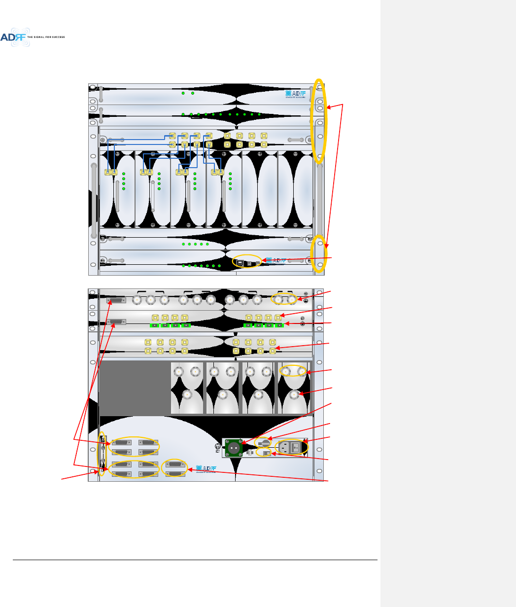
19” rack mount
Holes
Host / Remote Switch,
HE view/RU view Switch
& RJ-45 port
Optic Ports
Battery Backup
Port
RFU Duplex Port
AC Input &
On/Off Switch
BCU Interface Ports
Band Combiner Unit
(BCU)
Optic Unit (ODU RACK)
Channel Combiner
(CHC)
RF Channel Unit
(RFU)
Power Supply Unit
(PSU)
NMS Unit
Battery Backup
On/Off Switch
AC Input Voltage
Selection Switch
(110V/220V)
RFU Simplex
Port
OPT/ODU Interface Ports
AUX CH Interface
Ports
RF Ports
connected to OPT
RF Ports
connected to CHC
BCU Sum Port
Figure 1-1 ADX DAS HE Quick View
Ground terminal
Advanced RF Technologies, Inc.
16
DC IN +27VON/OFF
OUT
POWER
SOFT FAIL
HARD FAIL
IN
DC IN +27VON/OFF
OUT
POWER
SOFT FAIL
HARD FAIL
IN
DC IN +27VON/OFF
OUT
POWER
SOFT FAIL
HARD FAIL
IN
POWER
SOFT FAIL
HARD FAIL
COMM
OPTIC FAIL
DC IN +27V PSU ALARM RS-485GUI
OPTIC
ON/OFF
ON
1 2 3 4
ADDR
DANGER
1.2.3 RU Quick View
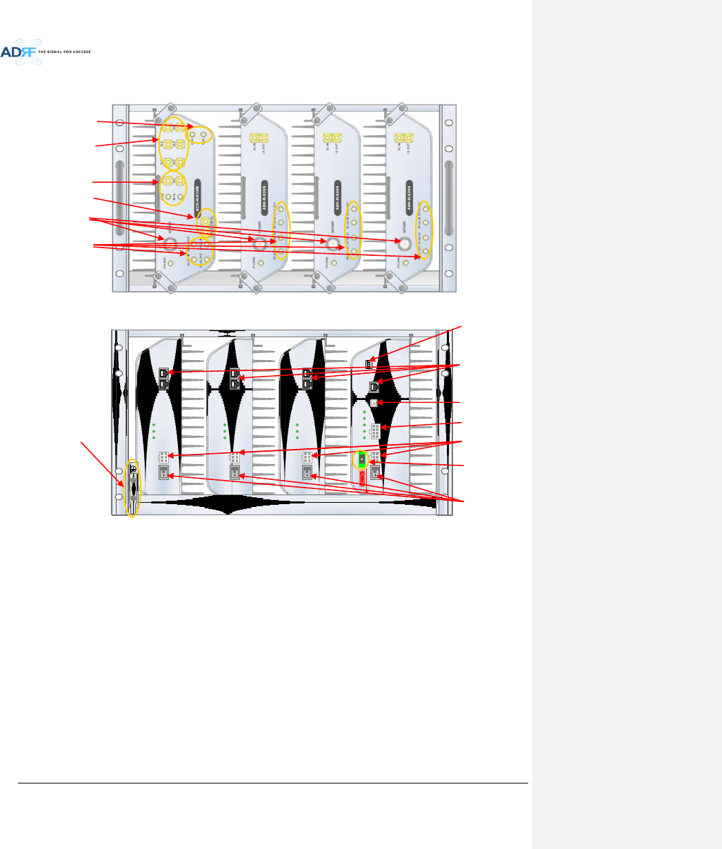
Figure 1-2 ADX DAS RU Quick View
Server Antenna Port
Ports for adding External
Filter, if needed
Power On/Off Switch
Expansion RF ports to
support additional (4)
slave RU.
Master RU
Slave RU #1
Slave RU #2
Slave RU #3
DC Input Ports
Optic Port
Port for receiving Alarm
Status of RU PSU
GUI Access Port
Communication port
between Master RU and
Slave RU (RS-485 interface)
Dip Switch for Master
Address Setting manually
Ground terminal
RF ports connected to
Slave RUs in same
chassis.
RF ports for Master RU
connection.
RF ports for VHF/UHF
Expansion.
Advanced RF Technologies, Inc.
17
1.3 Warnings and Hazards
Lithium Battery: CAUTION. RISK OF EXPLOSION IF BATTERY IS REPLACED BY INCORRECT TYPE.
DISPOSE OF USED BATTERIES ACCORDING TO INSTRUCTIONS.
Opening or tampering the ADX DAS will void all warranties.
WARRANTY
Actual separation distance is determined upon gain of antenna used.
Please maintain a minimum safe distance of at least 50 cm while operating near the donor and the server antennas.
RF EXPOSURE & ANTENNA PLACEMENT Guidelines
Working with the ADX DAS while in operation, may expose the technician to RF
electromagnetic fields that exceed FCC rules for human exposure. Visit the FCC website at
www.fcc.gov/oet/rfsafety to learn more about the effects of exposure to RF electromagnetic
fields.
WARNING! EXPOSURE TO RF
Opening the ADX DAS could result in electric shock and may cause
severe injury.
WARNING! ELECTRIC SHOCK
메모 [H1]: Donor antenna 설치에 대한
문구 삭제. (HK)
Advanced RF Technologies, Inc.
18
WANRNING. THIS is NOT a CONSUMER device. It is designed for installation by FCC LICENSEES and
QUALIFIED INSTALLERS. You MUST have an FCC LICENSE or express consent of an FCC Licensee to
operate this device. You MUST register Class B signal boosters (as defined in 47 CFR 90.219)
online at
www.fcc.gov/signal-boosters/registration. Unauthorized use may result in significant forfeiture
penalties, including penalties in excess of $100,000 for each continuing violation.
FCC Part 90 Class B
WANRNING. THIS is NOT a CONSUMER device. It is designed for installation by FCC LICENSEES and
QUALIFIED INSTALLERS. You MUST have an FCC LICENSE or express consent of an FCC Licensee to
operate this device. Unauthorized use may result in significant forfeiture penalties, including
penalties in excess of $100,000 for each continuing violation.
FCC Part 20
NOTE: This equipment has been tested and found to comply with the limits for a Class A
digital device, pursuant to part 15 of the FCC Rules. These limits are designed to provide
reasonable protection against harmful interference when the equipment is operated in a
commercial environment. This equipment generates, uses, and can radiate radio frequency
energy and, if not installed and used in accordance with the instruction manual, may cause
harmful interference to radio communications. Operation of this equipment in a residential area
is likely to cause harmful interference in which case the user will be required to correct the
interference at their own expense.
FCC Part 15 Class A
Ethernet Instructions: This equipment is for indoor use only. All cabling should be limited to
inside the building.
메모 [Y2]: 추가
15/02/03
메모 [Y3]: 추가
15/02/03
Advanced RF Technologies, Inc.
19
RSS-GEN, Sec. 7.1.2 – (transmitters)
Under Industry Canada regulations, this radio transmitter may only operate using an antenna of a type and
maximum (or lesser) gain approved for the transmitter by Industry Canada. To reduce potential radio
interference to other users, the antenna type and its gain should be so chosen that the equivalent
isotropically radiated power (e.i.r.p.) is not more than that necessary for successful communication.
Conformément à la réglementation d’Industrie Canada, le présent émetteur radio peut fonctionneravec
une antenne d’un type et d’un gain maximal (ou inférieur) approuvé pour l’émetteur par Industrie Canada.
Dans le but de réduire les risques de brouillage radioélectrique à l’intention desautres utilisateurs,
il faut choisir le type d’antenne et son gain de sorte que la puissance isotroperayonnée quivalente (p.i.r.e.)
ne dépassepas l’intensité nécessaire à l’établissement d’une communication satisfaisante.
RSS-GEN, Sec. 7.1.2 – (detachable antennas)
This radio transmitter (identify the device by certification number, or model number if Category II)has been
approved by Industry Canada to operate with the antenna types listed below with the maximum permissible
gain and required antenna impedance for each antenna type indicated. Antenna types not included in this list,
having a gain greater than the maximum gain indicated for that type, are strictly prohibited for use with this
device.
Le présent émetteur radio (identifier le dispositif par son numéro de certification ou son numéro de
Do not remove the protective covers on the fiber optic connectors until a connection is ready to be
made. Do not leave connectors uncovered when not connected.
The tip of the fiber optic connectors should not come into contact with any object or dust.
Refer to the cleaning procedure for information on the cleaning of the fiber tip.
Care of Fiber Optic Connectors
Fiber optic ports of the ADX DAS emit invisible laser radiation at the 1310, 1550nm wavelength
window.
To avoid eye injury never look directly into the optical ports, patch cords or optical cables. Do
not stare into beam or view directly with optical instruments. Always assume optical output is on.
Only technicians familiar with fiber optic safety practices and procedures should perform optical
fiber connections and disconnections of the ADX DAS and the associated cables.
The ADX DAS complies with 21 CFR 1040.10 and 1040.11 except for deviations pursuant to laser
notice No.50 (July26. 2001)@IEC 60825-1, Amendment2 (Jan. 2001).
Laser Safety

Advanced RF Technologies, Inc.
20
modèle s’il fait partie du matériel de catégorie I) a été approuvé par Industrie Canada pour fonctionner
avec les types d’antenne énumérés ci-dessous et ayant un gain admissible maximal et l’impédance requise
pour chaque type d’antenne. Les types d’antenne non inclus dans cette liste,ou dont le gain est supérieur
au gain maximal indiqué, sont strictement interdits pour l’exploitation de l’émetteur.
RF Radiation Exposure
This equipment complies with RF radiation exposure limits set forth for an uncontrolled environment.
This equipment should be installed and operated with a minimum distance of 50 cm between the radiator
and your body. This transmitter must not be co-located or operating in conjunction with any other antenna or
transmitter. RF exposure will be addressed at time of installation and the use of higher gain antennas
require larger separation distances.
RSS-102 RF Exposure
L’antenne (ou les antennes) doit être installée de façon à maintenir à tout instant une distance
minimum de au moins 50 cm entre la source de radiation (l’antenne) et toute personne physique.
Cet appareil ne doit pas être installé ou utilisé en conjonction avec une autre antenne ou émetteur.
Advanced RF Technologies, Inc.
21
2. BLOCK DIAGRAM
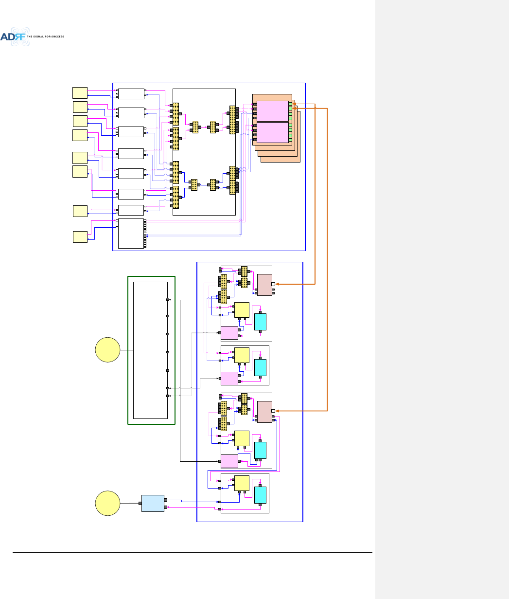
2.1 ADX DAS Block Diagram
Figure 2-1 ADX DAS Block Diagram
ODU
ODU
CCU
AWS BTS
PCS BTS
CELL
BTS
700M
BTS
Master RU
(P78)
Sub RU
(VU)
COM
PCS
CELL
AWS
700M
BT
WI-FI
ANT
4:1
HPA
Duplexer
RAU
AWS
RFU
TX
DPX
RX
DL
UL
700M
RFU
TX
DPX
RX
DL
UL
SMR
BTS
4:1
ODU
ODU
ODU#1
DL IN
V/UHF(136~512)
DL IN
(698~2690)
UL OUT
V/UHF(136~512)
UL OUT
(698~2690)
ODU#2
DL IN
V/UHF(136~512)
DL IN
(698~2690)
UL OUT
V/UHF(136~512)
UL OUT
(698~2690)
2:1 2:1
4:1 4:1 4:1 4:1
4:14:1
HPA
RAU
SMR
RFU
TX
DPX
RX
DL
UL
PS
RFU
TX
DPX
RX
DL
UL
PCS
RFU
TX
DPX
RX
DL
UL
CELL
RFU
TX
DPX
RX
DL
UL
4:1 4:1
2:1
2:1
2:12:1
Sub RU
(S89)
SMR
P78
BT BTS BT
RFU
DPX
RX
DL
UL
HPA
Duplexer
RAU
VU
RFU
TX
RX
DL
UL
PS
BTS
VHF/UHF
BTS
4:14:1
2:12:1
Master RU
(BT)
HPA
BPF
RAU
ANT VHF/UHF
Duplexer
HE
RU
ORU
ORU
Advanced RF Technologies, Inc.
22
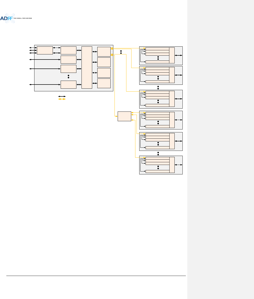
2.2 ADX DAS Topology
HE(Head End Unit) RU(Remote Unit)
Optic
RF
PCS RFU
(RF Interface Unit
with BTS or BDA)
Cellular RFU
(RF Interface Unit
with BTS or BDA)
AWS RFU
(RF Interface Unit
with BTS or BDA)
BCU(optional)
(Band Combiner Unit
with BTS or BDA)
Service Carrier #1
Service Carrier #2
Service Carrier #3
Service Carrier #1
Service Carrier #2
CHC-H
(HE Channel
Combiner)
700M RFU
(RF Interface Unit
with BTS or BDA)
Service Carrier #2
ODU-H
(RF to Optical)
ODU-H
(RF to Optical)
ODU-H
(RF to Optical)
ODU-H
(RF to Optical)
PCS Master RU
Combiner
Cellular Slave RU
AWS Slave RU
700M Slave RU
PCS Master RU
Combiner
Cellular Slave RU
AWS Slave RU
700M Slave RU
PCS Master RU
Combiner
Cellular Slave RU
AWS Slave RU
700M Slave RU
PCS Master RU
Combiner
Cellular Slave RU
AWS Slave RU
700M Slave RU
OEU
(Optic Expansion
Unit)
PCS Master RU
Combiner
Cellular Slave RU
AWS Slave RU
700M Slave RU
PCS Master RU
Combiner
Cellular Slave RU
AWS Slave RU
700M Slave RU
Figure 2-2 ADX DAS Topology
Advanced RF Technologies, Inc.
23
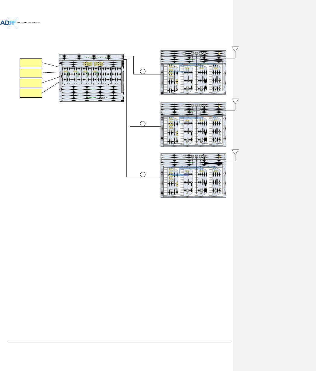
2.3 SISO Configuration
Figure 2-3 ADX DAS SISO Configuration
ADX-H-OPT
HE
ADX-H-PSU
POWER
CHG STS
ADX-H-CHC
DL 1 DL 2 DL 3 DL 4 DL 5 DL 6 DL 7 DL 8
UL 1 UL 2 UL 3 UL 4 UL 5 UL 6 UL 7 UL 8
POWER
ADX-H-RFU-P
UL_IN DL_OUT
SOFT FAIL
POWER
HARD FAIL
DL SIG LOW
ADS-H-RFU-7
UL_IN DL_OUT
SOFT FAIL
POWER
HARD FAIL
DL SIG LOW
ADX-H-RFU-C
UL_IN DL_OUT
SOFT FAIL
POWER
HARD FAIL
DL SIG LOW
ADX-H-RFU-A
UL_IN DL_OUT
SOFT FAIL
POWER
HARD FAIL
DL SIG LOW
LD FAIL 1-4 LINK1 LINK2 LINK3 LINK4 LD FAIL 5-8 LINK5 LINK6 LINK7 LINK8
LOW BATT
AC FAIL
DC FAIL
ADX-H-NMS
HOST
REMOTE
POWER
SOFT-FAIL-H
HE VIEW
RU VIEW
SOFT-FAIL-R
HARD-FAIL-H
HARD-FAIL-R
LINK FAIL-H
LINK FAIL-R
700MHz
eNode-B
Cellular
BTS
PCS
BTS
AWS
BTS
RF
ADX-R-CHC
ADX-H-PSU
CELL700MPCS
COM WIFI
Mon
UL4UL3UL2UL1
ADX-R-P30M
DL4DL3DL2DL1M-DL
M-UL
ADX-R-730S
RU
SERVER
VHF DL
Mon
VHF UL
E-DL E-UL
EF-UL-IN
EF-UL-OUT
EF-DL-OUT
EF-DL-IN
DL-IN UL-OUT
EF-UL-INEF-DL-OUT EF-UL-OUTEF-DL-IN
ADX-R-C30S
SERVER
Mon
DL-IN UL-OUT
EF-UL-INEF-DL-OUT EF-UL-OUTEF-DL-IN
ADX-R-A30S
SERVER
Mon
DL-IN UL-OUT
EF-UL-INEF-DL-OUT EF-UL-OUTEF-DL-IN
POWER
CHG STS
LOW BATT
AC FAIL
DC FAIL
Optic
Optic
Optic
AWS
ADX-R-CHC
ADX-H-PSU
CELL700MPCS
COM WIFI
Mon
UL4UL3UL2UL1
ADX-R-P30M
DL4DL3DL2DL1M-DL
M-UL
ADX-R-730S
RU
SERVER
VHF DL
Mon
VHF UL
E-DL E-UL
EF-UL-IN
EF-UL-OUT
EF-DL-OUT
EF-DL-IN
DL-IN UL-OUT
EF-UL-INEF-DL-OUT EF-UL-OUTEF-DL-IN
ADX-R-C30S
SERVER
Mon
DL-IN UL-OUT
EF-UL-INEF-DL-OUT EF-UL-OUTEF-DL-IN
ADX-R-A30S
SERVER
Mon
DL-IN UL-OUT
EF-UL-INEF-DL-OUT EF-UL-OUTEF-DL-IN
POWER
CHG STS
LOW BATT
AC FAIL
DC FAIL
AWS
Advanced RF Technologies, Inc.
24
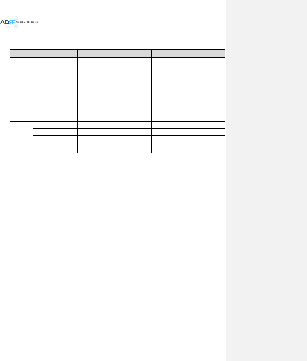
2.4 ADX-DAS Scalability
Table 2-1 ADX-DAS Scalability
Unit
Scalability
Remarks
Supported band
700MHz, Cellular, AWS 1W/2W, PCS
1W/2W, SMR800/900, PS700, VHF, UHF,
BRS
700MHz includes Lower A, Lower B,
Lower C, and Upper C
HE
RFU
Up to 8
up to 6: card type
7th & 8th RFU: 19” rack type
NMS
1
Channel Combiner
1
Optic Unit
Up to 4
Band Combiner Unit
Up to 4
To support multiple carriers
Power Supply Unit
(AC or DC)
1
Capable of supplying power to 8 RFUs, 4
BCUs, 4 OPTs and NMS.
RU
RU
Up to 60
OEU
Up to 4
PSU
Adaptor type
1 per remote module
19” rack mount
(AC or DC)
1
Capable of supplying power to 8 Remote
Modules

Advanced RF Technologies, Inc.
25
3. ADX OVERVIEW
3.1 Head End
The head end unit must always be connected to the Base Station using a direct cabled connection. This
system has not been approved for use with a wireless connection via server antenna to the base station.
Head end components include:
ADX-H-NMS (Network Management System)
ADX-H-CHC (Head End Channel Combiner)
ADX-H-PSU (Head End Power Supply)
Up to [4] ADX-H-BCU (Band Combiner Unit)
Up to [8] ADX-H-RFU-x (RF Unit)
Up to [4] ADX-H-RACK-ODU (Optical Unit rack) each ADX-H-RACK-ODU enables to have up to 2
ODU(ADX-H-ODU-4-X)s
Specifications
- Size: 19.0 x 14.6 x 12.2 inches (482 x 370 x 311 mm)
- Weight: 83.7 lbs (38.0 Kg)@4 RFU, CHC-H, PSU and NMS
- Power Consumption: 52W@4 RFU, 2 ODUs and NMS, 28W@1 RFU, 2 ODUs and NMS
- Power Input: 110VAC or -48VDC(optional)
- Supports the ADRF-BBU for external battery backup solution
ADX-H-NMS
POWER
SOFT FAIL-H
SOFT FAIL-R
HARD FAIL-H
HARD FAIL-R
LINK FAIL-H
LINK FAIL-R
HOST HE VIEW
REMOTE RU VIEW
ADX-H-PSU
POWER
CHG STS
LOW BATT
AC FAIL
DC FAIL
DL OUTUL IN
HARD FAIL
DL SIG LOW
SOFT FAIL
POWER
ADX-H-RFU-P
DL OUTUL IN
HARD FAIL
DL SIG LOW
SOFT FAIL
POWER
ADX-H-RFU-7
DL OUTUL IN
HARD FAIL
DL SIG LOW
SOFT FAIL
POWER
ADX-H-RFU-C
DL OUTUL IN
HARD FAIL
DL SIG LOW
SOFT FAIL
POWER
ADX-H-RFU-A
ADX-H-CHC
UL1 UL2 UL3 UL4
DL1 DL2 DL3 DL4
UL5 UL6 UL7 UL8
DL5 DL6 DL7 DL8
LD FAIL5-8 LINK5 LINK6 LINK7 LINK8LD FAIL1-4 LINK1 LINK2 LINK3 LINK4POWER
ADX-H-RACK-ODU
SOFT FAILPOWER
ADX-H-BCU-P
Figure 3-1 Head End Front View
메모 [Y4]: 추가
15/02/03
Advanced RF Technologies, Inc.
26
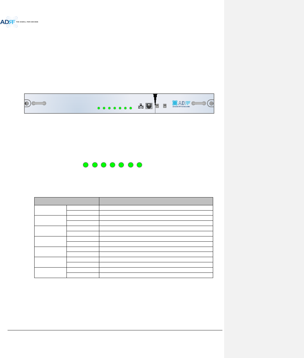
3.1.1 NMS (Network Management System)
Functions and features
- Supports SNMP v1, v2, and v3 (get, set & trap) and web-based GUI Interface.
- Monitors alarms and status
- Provides control interfaces with all subordinate modules
- Provides overall DAS structure via the auto tree update function
Spec
- Size: 19.0 x 12.1 x 1.7 inches
- Weight: 5.5 lbs
ADX-H-NMS
POWER
SOFT FAIL-H
SOFT FAIL-R
HARD FAIL-H
HARD FAIL-R
LINK FAIL-H
LINK FAIL-R
HOST HE VIEW
REMOTE RU VIEW
Figure 3-2 ADX-H-NMS Front View
3.1.1.1 LEDs
NMS has LEDs on the front panel as shown in Figure 3-3.
POWER
SOFT-FAIL-H
SOFT-FAIL-R
HARD-FAIL-H
HARD-FAIL-R
LINK FAIL-H
LINK FAIL-R
Figure 3-3 NMS LED
Table 3-1 NMS LED Specifications
ADX DAS-NMS
Specifications
Power
Solid Green
NMS power is ON
OFF
NMS power is OFF
SOFT FAIL-H
Solid Yellow
HE Soft Fail alarm exists in the system
Solid Green
No HE Soft Fail alarms are present in the system
SOFT FAIL-R
Solid Yellow
RU Soft Fail alarm exists in the system
Solid Green
No RU Soft Fail alarms are present in the system
HARD FAIL-H
Solid Red
HE Hard Fail alarm exists in the system
Solid Green
No HE Hard Fail alarms are present in the system
HARD FAIL-R
Solid Red
RU Hard Fail alarm exists in the system
Solid Green
No RU Hard Fail alarms are present in the system
LINK FAIL-H
Solid Yellow
HE Link Fail alarm exists in the system
Solid Green
No HE Link Fail alarms are present in the system
LINK FAIL-R
Solid Yellow
RU Link Fail alarm exists in the system
Solid Green
No RU Link Fail alarms are present in the system
Advanced RF Technologies, Inc.
27
3.1.1.2 Ethernet Port
The Ethernet port can be used to communicate directly with the ADX DAS using a RJ-45 crossover cable or can
also be used to connect the ADX DAS to an external modem box.
HOST HE VIEW
REMOTE RU VIEW
Figure 3-4 Ethernet Port
3.1.1.3 Host/Remote Switch
The Host/Remote Switch allows the user to switch the default Repeater IP, Subnet Mask, and Gateway of the
repeater to an alternative setup. These settings can be adjusted by logging into the ADX DAS in HOST mode and
configuring the settings under the Modem Box Setting section under the Install Page of NMS.
Once the settings are set, flipping the switch to the REMOTE position will reboot NMS module with the new
alternate settings. Please note that when the NMS is set to the REMOTE position, DHCP is disabled and the NMS
will not automatically assign an IP address to any device that connects directly to the NMS.
HOST HE VIEW
REMOTE RU VIEW
Figure 3-5 Host/Remote Switch
Host IP: 192.168.63.1 (Fixed IP, unable to modify this IP address)
Remote IP: 192.168.63.5 (Default IP, but can be modified in Host mode)
3.1.1.4 HE View/RU View Switch
The HE View/RU View Switch allows the user to disable the periodic monitoring performed by the NMS. In the
HE view mode, the NMS monitors the status of all subordinate units connected to NMS but when switched to RU
view the NMS does not monitor the subordinate units. RU View mode will allow the user to go to a RU and
monitor/control the HE. If the NMS is set to the HE View mode and tries to connect to a RU to monitor the HE,
data collisions between the NMS and RU may prevent the user from properly monitoring or configuring the HE
when at the RU.
HOST HE VIEW
REMOTE RU VIEW
Figure 3-6 HE View/RU View Switch
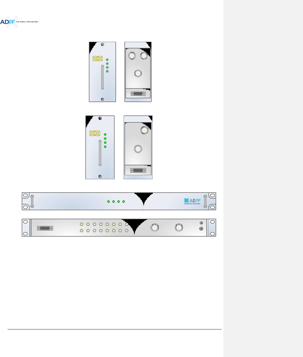
Advanced RF Technologies, Inc.
28
3.1.2 RFU (ADX-H-RFU-x)
DL OUTUL IN
HARD FAIL
DL SIG LOW
SOFT FAIL
POWER
ADX-H-RFU-P
DL IN UL OUT
DPX
ADX-H-RFU-P
Figure 3-7 RFU Front & Rear View (excluding BT and VU)
Figure 3-8 RFU Front & Rear View for BT
Figure 3-9 RFU Front & Rear View for VU
Functions and features
- Provide RF interface with BTS
- Each RFU has independent gain control and filtering
- Modular type and hot swappable
- Supports duplex port or simplex TX & RX ports
- Easily support additional frequency bands by adding a single RFU
- Reduces complexity and overall equipment size
Specifications
- Size: 12.8 x 6.2 x 2.8 inches
- Weight: 7.3 lbs
UL OUT
DPX
ADX-H-RFU-BT
DL OUTUL IN
HARD FAIL
DL SIG LOW
SOFT FAIL
POWER
ADX-H-RFU-BT
ADX-H-RFU-VU-R
POWER
SOFT FAIL
HARD FAIL
DL SIG LOW
ADX-H-RFU-VU-R
DL IN UL OUT
DL OUT
UL IN
DL 1DL 2DL 3DL 4DL 5DL 6DL 7DL 8
UL 1UL 2UL 3UL 4UL 5UL 6UL 7UL 8
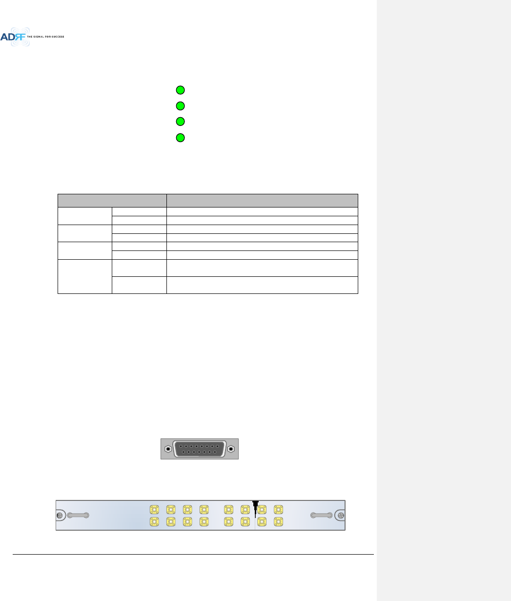
Advanced RF Technologies, Inc.
29
3.1.2.1 LEDs
RFU has LEDs on the front panel as shown in Figure 3-10.
HARD FAIL
DL SIG LOW
SOFT FAIL
POWER
Figure 3-10 RFU LED
Table 3-2 RFU LED Specifications
ADX DAS-Module
Specifications
Power
Solid Green
Module power is ON.
OFF
Module power is OFF.
Soft Fail
Solid Yellow
Soft Fail alarm exists in the RFU.
Solid Green
No Soft Fail alarms are present in the RFU.
Hard Fail
Solid Red
Hard Fail alarm exists in the RFU.
Solid Green
No Hard Fail alarms are present in the RFU.
DL SIG LOW
Solid Yellow
When DL input signal level is lower than the defined threshold
level. (default threshold value: -5dBm)
Solid Green
When DL input signal level is upper than the defined threshold
level.
3.1.2.2 RF Ports
3.1.2.2.1 DL IN/UL OUT & DPX ports
DL IN/UL OUT & DPX Ports (refer to Figure 3-7) are located at the back of RFU and can be connected directly to
the BTS. The RFU can support incoming signal strength from 0 to 25dBm(in case of BT and VU, -15~37dBm).
BT RFU does not have DL IN port because of TDD(Time division duplex) system.
VU RFU does not have DPX port because there is externally optional Duplexer customized by user requirement
for VHF/UHF system.
3.1.2.2.2 DL OUT/UL IN
DL OUT/UL IN Ports (refer to Figure 3-7) are located at the front of the RFU and connect directly to the HE
Channel Combiner (ADX-H-CHC).
3.1.2.3 Communication Port
The ADX-H-NMS monitors and controls the RFU via this port. DC Power is also provided to the RFU via this port.
Figure 3-11 Communication Port (RFU)
3.1.3 Channel Combiner (ADX-H-CHC)
ADX-H-CHC
UL1 UL2 UL3 UL4
DL1 DL2 DL3 DL4
UL5 UL6 UL7 UL8
DL5 DL6 DL7 DL8
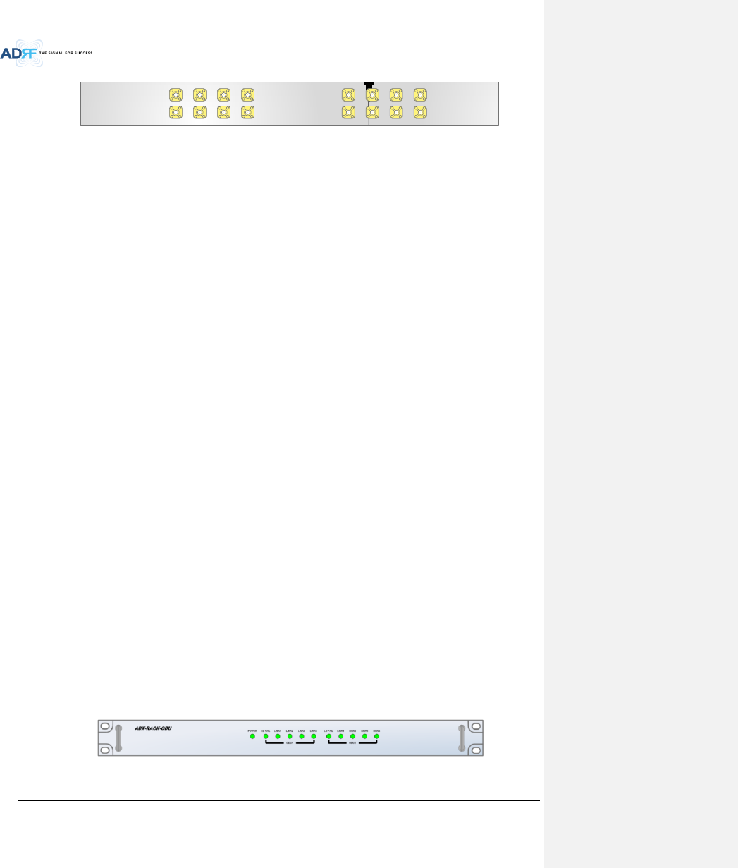
Advanced RF Technologies, Inc.
30
UL5UL6UL7UL8
DL5DL6DL7DL8
UL1UL2UL3UL4
DL1DL2DL3DL4
Figure 3-12 ADX-H-CHC Front & Rear View
Functions & Features
- Combines DL signals received from each RFU and feeds the combined signals to the ADX-H-OPT
- Combines UL signals received from each RU and feeds the combined signal to the ADX-H-RFU
- Supports up to 8 RFUs and (4) ADX-H-OPT-8 or (4)ADX-H-OPT-4
- Channel Combiner is not connected to VU RFU because VU RFU internally includes 8way combiner for
connection to 8 ODUs’ VHF ports
Specifications
- Size: 16.9 x 12.9 x 1.7 inches
- Weight: 11.0 lbs
3.1.3.1 RF ports
3.1.3.1.1 RF ports at the front panel (DL 1 to DL 8, UL 1 to UL 8)
DL 1(to DL 8) & UL 1(to UL 8) RF ports are connected to DL OUT/UL IN Ports at the front panel of RFU.
Receive the downlink signal from each RFU
Split the uplink signal received from ODU to each RFU
3.1.3.1.2 RF ports at the back panel (DL 1 to DL 8, UL 1 to UL 8)
DL 1(to DL 8) & UL 1(to UL 8) RF ports are connected to DL IN/UL OUT Ports at the back panel of OPT.
Transfer the combined downlink signals to OPT
Receive the uplink signal from ODU
3.1.3.2 RF ports
3.1.3.2.1 RF ports at the front panel( DL 1 to DL 8, UL 1 to UL 8)
DL 1(to DL 8) & UL 1(to UL 8) RF ports are connected to DL OUT/UL IN Ports at the front panel of RFU.
Receive the downlink signal from each RFU
Split the uplink signal received from ODU to each RFU
3.1.3.2.2 RF ports at the back panel( DL 1 to DL 8, UL 1 to UL 8)
DL 1(to DL 8) & UL 1(to UL 8) RF ports are connected to DL IN/UL OUT Ports at the back panel of OPT.
Transfer the combined downlink signals to ODU
Receive the uplink signal from ODU
3.1.4 Optic Distribution Unit (ADX-H-ODU + ADX-RACK-ODU)
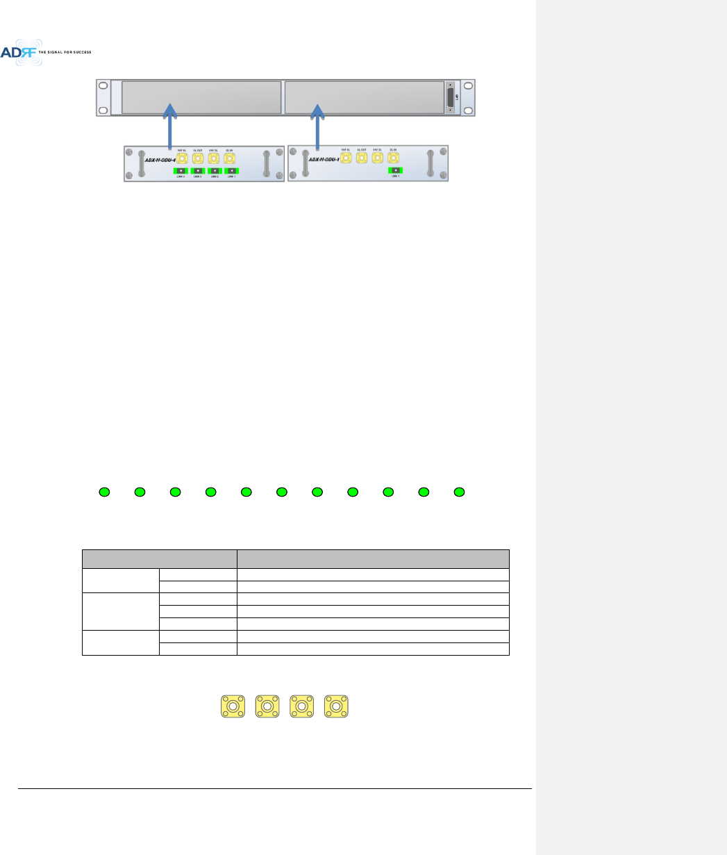
Advanced RF Technologies, Inc.
31
Figure 3-13 ADX-RACK-ODU + ADX-H-ODU-4/1 Front & Rear View
Functions & Features
- Converts signal from RF to optic and transports signals to Master RU
- ADX-RACK-ODU can support up to (2) ADX-H-ODU units
- ADX-H-ODU-4-X can supports up to (4) Master RUs with up to 5 dBo loss (including optical connection loss)
- ADX-H-ODU-1-X can supports (1) Master RU with up to 10dBo loss (including optical connection loss)
- Minimizes the number of optic fiber cable need by transporting multi band signals over a single strand of
fiber using WDM technology.
- VHF DL and VHF UL ports for VHF/UHF band transmission
Spec
- ADX-RACK-ODU
o Size: 19.0 x 12.9 x 1.7 inches (482 x 327 x 44 mm)
o Weight: 4.2 lbs
- ADX-ODU-1/4
o Size: 7.96 x 7.17 x 1.64 inches (202 x 182 x 41.5 mm)
o Weight: 3.2 lbs
3.1.4.1 LEDs
The ADX-H-OPT-8 has the following LEDs on the front panel as shown in Figure 3-14. The ADX-H-OPT-4 has the
same LEDs except for LD FAIL 5-8, LINK 5, LINK 6, LINK 7, AND LINK 8.
POWER LD FAIL 1-4 LINK1 LINK2 LINK3 LINK4 LD FAIL 5-8 LINK5 LINK6 LINK7 LINK8
Figure 3-14 ADX-H-OPT-8 LED
Table 3-3 ODU Rack LED Specifications
ADX DAS-Module
Specifications
Power
Solid Green
Module power is ON
OFF
Module power is OFF
LD FAIL 1-4/
LD FAIL 5-8
OFF
ODU is not installed
Solid Yellow
LD Fail alarm exists in the ODU
Solid Green
No LD Fail alarm is present in the ODU
LINK1 to LINK8
Solid Yellow
PD Fail alarm exists
Solid Green
No PD Fail alarm is present
3.1.4.2 RF Ports
VHF UL 1 UL OUT 1 VHF DL 1 DL IN 1
Figure 3-15 ODU RF Ports
3.1.4.2.1 DL IN/UL OUT
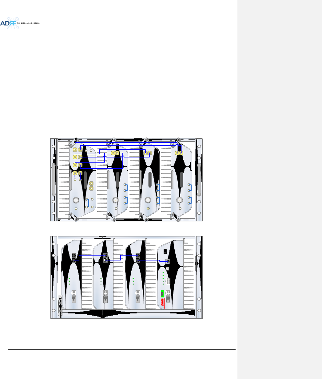
Advanced RF Technologies, Inc.
32
The combined downlink signal received from ADX-H-CHC is transferred to the DL IN 1(or 2) at the back of OPT.
The UL OUT port connects any of the ports on back of the ADX-H-CHC labeled UL 1 ~8.
3.1.4.2.2 VHF DL/VHF UL
VHF DL/UHF UL ports are used to support Public Safety in the VHF & UHF frequency bands. VHF/UHF signals
for Public Safety bypass the ADX-H-CHC and connect directly to the VHF DL/UHF UL ports of the ADX-H-OPT.
3.2 Remote Unit
The remote unit is composed of a (1) Master RU and up to (7) Slave RU’s (ADX-R-4WS is required when
connecting more than 3 Slave RU’s). A power source, either the ADX-R-ADP-30 (supports [1] Master/Slave RU) or
the ADX-R-PSU-30 (supports up to [8] Master/Slave RU) is required.
Specifications
- Size: 19.0 x 12.9 x 10.5 inches
- Weight: 61.0 lbs
- Power Input: 110VAC or -48VDC (optional)
ADX-R-730S
DL IN
SERVER
CPL(-30dB)
UL OUT
EF-DL OUT EF-DL IN EF-UL IN EF-UL OUT
ADX-R-C30S
DL IN
SERVER
CPL(-30dB)
UL OUT
EF-DL OUT EF-DL IN EF-UL IN EF-UL OUT
ADX-R-A30S
DL IN
SERVER
CPL(-30dB)
UL OUT
EF-DL OUT EF-DL IN EF-UL IN EF-UL OUT
SERVER
UL1 UL2 UL3 UL4
ADX-R-P30M
DL1 DL2 DL3 DL4
M-DL
M-UL
CPL(-30dB)
E-DL
E-UL
VHF DL VHF UL
EF-DL IN EF-DL OUT
EF-UL INEF-UL OUT
Figure 3-16 RU Front View
Figure 3-17 RU Rear View
DC IN +27VON/OFF
OUT
POWER
SOFT FAIL
HARD FAIL
IN
DC IN +27VON/OFF
OUT
POWER
SOFT FAIL
HARD FAIL
IN
DC IN +27VON/OFF
OUT
POWER
SOFT FAIL
HARD FAIL
IN
POWER
SOFT FAIL
HARD FAIL
COMM
OPTIC FAIL
DC IN +27V PSU ALARM RS-485GUI
OPTIC
ON/OFF
ON
1 2 3 4
ADDR
DANGER
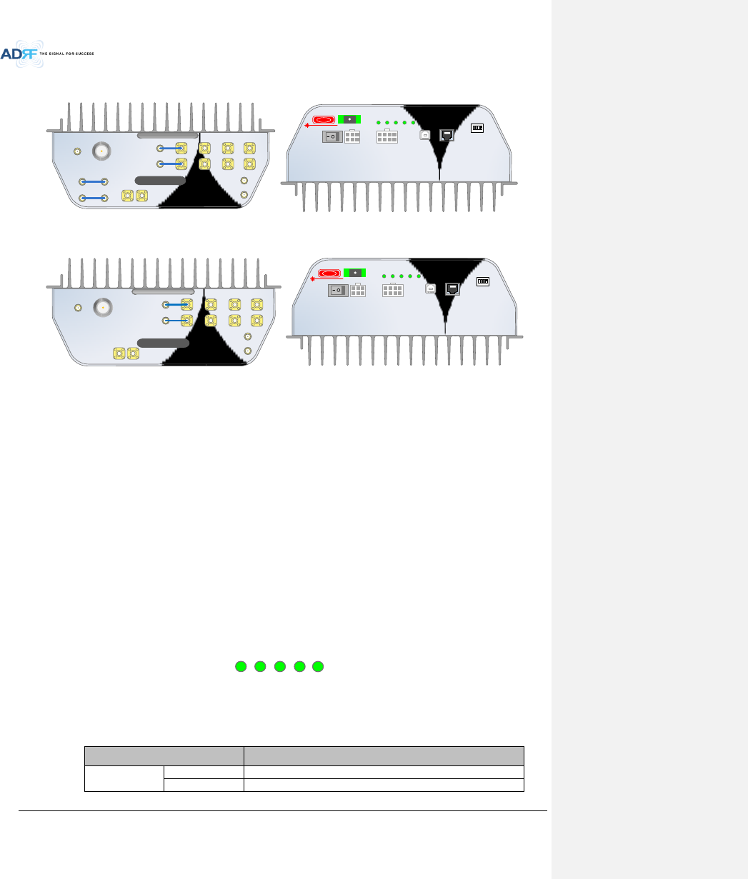
Advanced RF Technologies, Inc.
33
3.2.1 ADX-R-x3xM (Master RU)
SERVER
UL1 UL2 UL3 UL4
ADX-R-P30M
DL1 DL2 DL3 DL4
M-DL
M-UL
CPL(-30dB)
E-DL
E-UL
VHF DL VHF UL
EF-DL IN EF-DL OUT
EF-UL INEF-UL OUT
POWER
SOFT FAIL
HARD FAIL
COMM
OPTIC FAIL
DC IN +27V PSU ALARM RS-485GUI
OPTIC
ON/OFF
ON
1 2 3 4
ADDR
DANGER
Figure 3-18 Master RU Front & Rear View(excluding BT)
POWER
SOFT FAIL
HARD FAIL
COMM
OPTIC FAIL
DC IN +27V PSU ALARM RS-485GUI
OPTIC
ON/OFF
ON
1 2 3 4
ADDR
DANGER
Figure 3-19 Master RU Front & Rear View only for BT
Functions & Features
- Converts DL optic signal to a RF signal
- Converts UL RF signal to an optic signal
- Splits the converted RF signals and which provide RF to Slave RU’s
- Transmits DL signal and receives UL signal through server antenna
- Supports up to 7 slave RUs
- Individually wall-mountable or 19” rack-mountable (requires ADX-R-CHA)
- Supports external filters via DL and UL pass-through ports
Specifications
- Size: 11.8 x 9.8 x 4.5 inches
- Weight: 13.2 lbs
3.2.1.1 LEDs
Master RU’s have the following LEDs on the front panel as shown in Figure 3-20.
POWER
SOFT-FAIL
HARD-FAIL
OPTIC FAIL
COMM
Figure 3-20 Master RU LED
Table 3-4 Master RU LED Specifications
ADX DAS-Module
Specifications
Power
Solid Green
Module power is ON
OFF
Module power is OFF
SERVER
UL1 UL2 UL3 UL4
ADX-R-BT33MX
DL1 DL2 DL3 DL4
M-DL
M-UL
CPL(-30dB)
E-DL
E-UL
VHF DL VHF UL
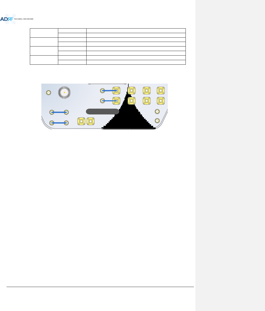
Advanced RF Technologies, Inc.
34
Soft Fail
Solid Yellow
Soft Fail alarm exists in the Master RU
Solid Green
No Soft Fail alarms are present in the Master RU
Hard Fail
Solid Red
Hard Fail alarm exists in the Master RU
Solid Green
No Hard Fail alarms are present in the Master RU
Optic Fail
Solid Yellow
Optic Fail alarm exists in the Master RU
Solid Green
No Optic Fail alarm is present in the Master RU
COMM
Solid Yellow
COMM Fail alarm exists in the Master RU
Solid Green
No COMM Fail alarm is present in the Master RU
3.2.1.2 RF Ports
Figure 3-21 RF Ports (Master RU)
3.2.1.2.1 M-DL/M-UL, DL1 to DL4 & UL1 to UL4
M-DL/M-UL ports
- Master RU units will come with the M-DL and M-UL ports pre-connected to the DL1 and UL1 ports.
DL2 to DL4 & UL2 to UL4 ports
- Slave RU’s connect to the DL2 ~DL4 and UL2~UL4 ports.
3.2.1.2.2 E-DL/E-UL
The E-DL/E-UL ports connect to the ADX-R-4WS (4-way splitter)
The ADX-R-4WS will provide an additional (4) DL and UL ports to connect up to (4) additioanl Slave RU’s
ADX-R-4WS divides the output of E-DL port to extended slave RUs and combines/transfers UL signal received
from extended slave RUs to E-UL port.
3.2.1.2.3 VHF DL/VHF UL
Connects to the ADX-R-V25S (VHF Slave RU) for public safety service in the VHF/UHF bands
3.2.1.2.4 SERVER & CPL
Server Port
- Connects directly to a server antenna or the ADX-R-CHC (remote channel combiner)
CPL Port
- 30dB coupling port off of the server port
3.2.1.2.5 EF-DL IN/EF-DL OUT & EF-UL IN/EF- UL OUT
Connects to an external DL/UL filter
DL external filter can be used to reduce DL out-band emissions
UL external filter can be used to reduce out-band frequenies
BT RU does not have external filter ports because there are no issues for external filtering
SERVER
UL1 UL2 UL3 UL4
ADX-R-P30M
DL1 DL2 DL3 DL4
M-DL
M-UL
CPL(-30dB)
E-DL
E-UL
VHF DL VHF UL
EF-DL IN EF-DL OUT
EF-UL INEF-UL OUT
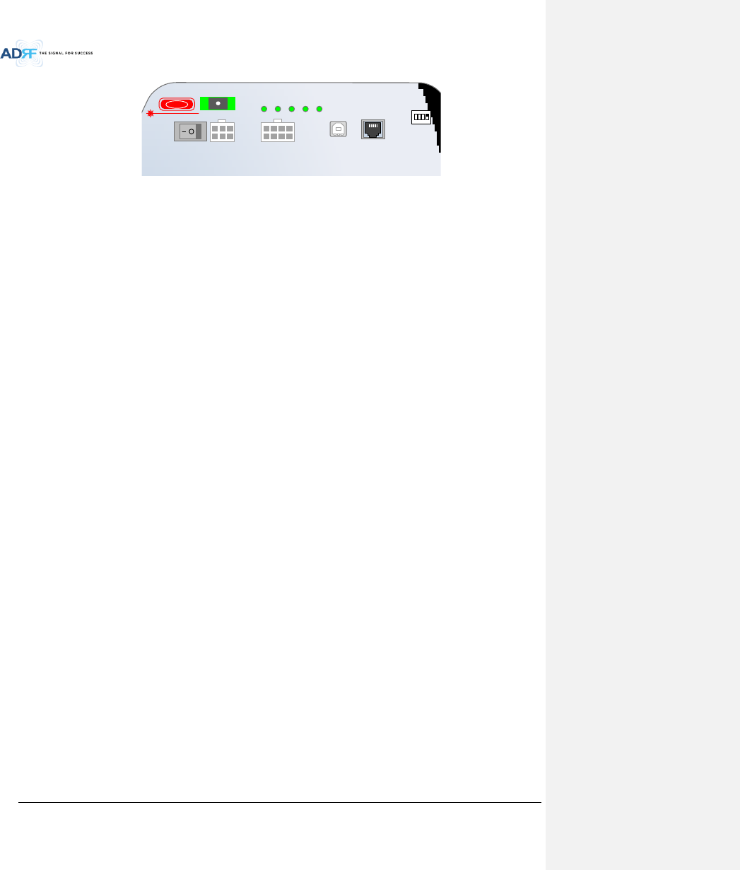
Advanced RF Technologies, Inc.
35
Figure 3-22 Ports at the back panel (Master RU)
3.2.1.3 Optic Port
Connets to ADX-H-OPT-8, ADX-H-OPT-4, or ADX-R-OEU via optic line
3.2.1.4 Power On/Off Switch & DC IN Port
Power On/Off switch
- Master RU Power On/Off switch
DC IN Port
- Connects to DC output port of AC/DC adapter (ADX-R-ADP-30) or RU PSU (ADX-R-PSU-30)
3.2.1.5 PSU Alarm Port
Connects to the ADX-R-PSU-30
The ADX-H-NMS and the Master RU can monitor the status of the ADX-H-PSU-30 via this port
3.2.1.6 GUI Port
Connects to a laptop via USB cable
Monitor/control the RU and the HE connected to the RU using User GUI, which is a Windows based program.
ADRF 32-bit or 64-bit drivers will also be required to access the RU using the User GUI.
3.2.1.7 RS-485 Port
Slave RU should be connected to master RU in a diasy chain structure using RS-485 line to monitor and control
slave RUs.
The RS-485 cable connected to master RU should be connected to RS-485 IN port of slave RU. When a slave
RU is connected to another slave RU, then the RS-485 cable should be connected from the RS-485 OUT port to
the RS-485 IN of the 2nd Slave RU. (Figure 3-23)
If RS-485 port connections between Remote Modules are not correct, master RU will not be able to recognize
all subordinate slave RUs. (Figure 3-24)
WARNING! The RS-485 ports should NEVER be connected to the Ethernet port of laptop or Ethernet Network
Equipment. Doing so may cause serious damage to the Remote Modules or network equipments. (Figure
3-25)
POWER
SOFT FAIL
HARD FAIL
COMM
OPTIC FAIL
DC IN +27V PSU ALARM RS-485GUI
OPTIC
ON/OFF
ON
1 2 3 4
ADDR
DANGER
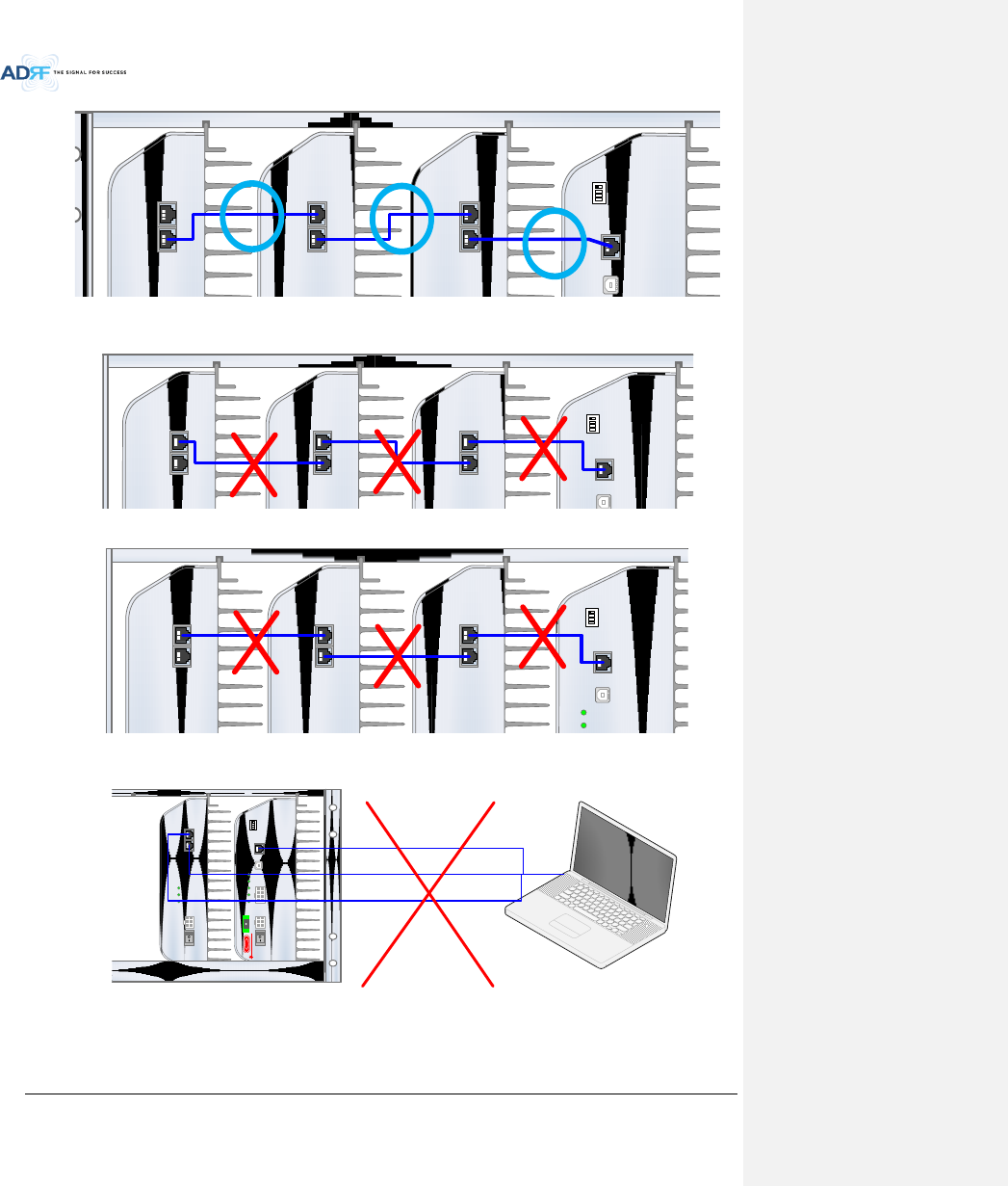
Advanced RF Technologies, Inc.
36
Figure 3-23 Correct RS-485 connection between Master RU and Slave RU or between Slave RUs
Figure 3-24 Wrong RS-485 connection between Master RU and Slave RU or between Slave RUs
Figure 3-25 Do NOT connect RS-485 ports of Remote Module to network equipment port
3.2.1.8 ADDR
DC IN +27VON/OFF
OUT
POWER
SOFT FAIL
HARD FAIL
IN
DC IN +27VON/OFF
OUT
POWER
SOFT FAIL
HARD FAIL
IN
DC IN +27VON/OFF
OUT
POWER
SOFT FAIL
HARD FAIL
IN
POWER
SOFT FAIL
HARD FAIL
COMM
OPTIC FAIL
DC IN +27V PSU ALARM RS-485GUI
OPTIC
ON/OFF
ON
1 2 3 4
ADDR
DANGER
DC IN +27VON/OFF
OUT
POWER
SOFT FAIL
HARD FAIL
IN
DC IN +27VON/OFF
OUT
POWER
SOFT FAIL
HARD FAIL
IN
DC IN +27VON/OFF
OUT
POWER
SOFT FAIL
HARD FAIL
IN
POWER
SOFT FAIL
HARD FAIL
COMM
OPTIC FAIL
DC IN +27V PSU ALARM RS-485GUI
OPTIC
ON/OFF
ON
1 2 3 4
ADDR
DANGER
DC IN +27VON/OFF
OUT
POWER
SOFT FAIL
HARD FAIL
IN
DC IN +27VON/OFF
OUT
POWER
SOFT FAIL
HARD FAIL
IN
DC IN +27VON/OFF
OUT
POWER
SOFT FAIL
HARD FAIL
IN
POWER
SOFT FAIL
HARD FAIL
COMM
OPTIC FAIL
DC IN +27V PSU ALARM RS-485GUI
OPTIC
ON/OFF
ON
1 2 3 4
ADDR
DANGER
DC IN +27VON/OFF
OUT
POWER
SOFT FAIL
HARD FAIL
IN
POWER
SOFT FAIL
HARD FAIL
COMM
OPTIC FAIL
DC IN +27V PSU ALARM RS-485GUI
OPTIC
ON/OFF
ON
1 2 3 4
ADDR
DANGER
Laptop or Network Equipment
or
or
DAMAGE
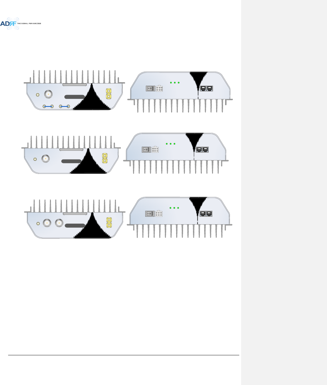
Advanced RF Technologies, Inc.
37
The ID of master RU can be set manually using ADDR switch. This switch should only be use if instructed by
ADRF Technical Support.
3.2.2 ADX-R-xxxS/ADX-R-BTxxS/ADX-R-VU25S (Slave RU)
ADX-R-C30S
DL IN
SERVER
CPL(-30dB)
UL OUT
EF-DL OUT EF-DL IN EF-UL IN EF-UL OUT
DC IN +27VON/OFF
OUT
POWER
SOFT FAIL
HARD FAIL
IN
Figure 3-26 Slave RU Front & Rear View (excluding BT and VU)
ADX-R-BT33S
DL IN
SERVER
CPL(-30dB)
UL OUT
DC IN +27VON/OFF
OUT
POWER
SOFT FAIL
HARD FAIL
IN
Figure 3-27 Slave RU Front & Rear View (BT)
DC IN +27VON/OFF
OUT
POWER
SOFT FAIL
HARD FAIL
IN
Figure 3-28 Slave RU Front & Rear View (excluding VU)
Functions & Features
- Transmits DL signal and receives UL signal through server antenna port
- Individually wall-mountable or 19” rack-mountable (requires ADX-R-CHA)
- Supports external filters via DL and UL pass-through ports
Specification
- Size: 11.8 x 9.8 x 3.7 inches (300 x 249.6 x 94.5 mm)
- Weight: 11.7 lbs (5.3 kg)
3.2.2.1 LEDs
ADX-R-x30S has the following LEDs on the front of the Slave RU as shown below in Figure 3-29.
ADX-R-VU25S
DL IN
DL OUT
CPL(-30dB)
UL OUT
UL IN
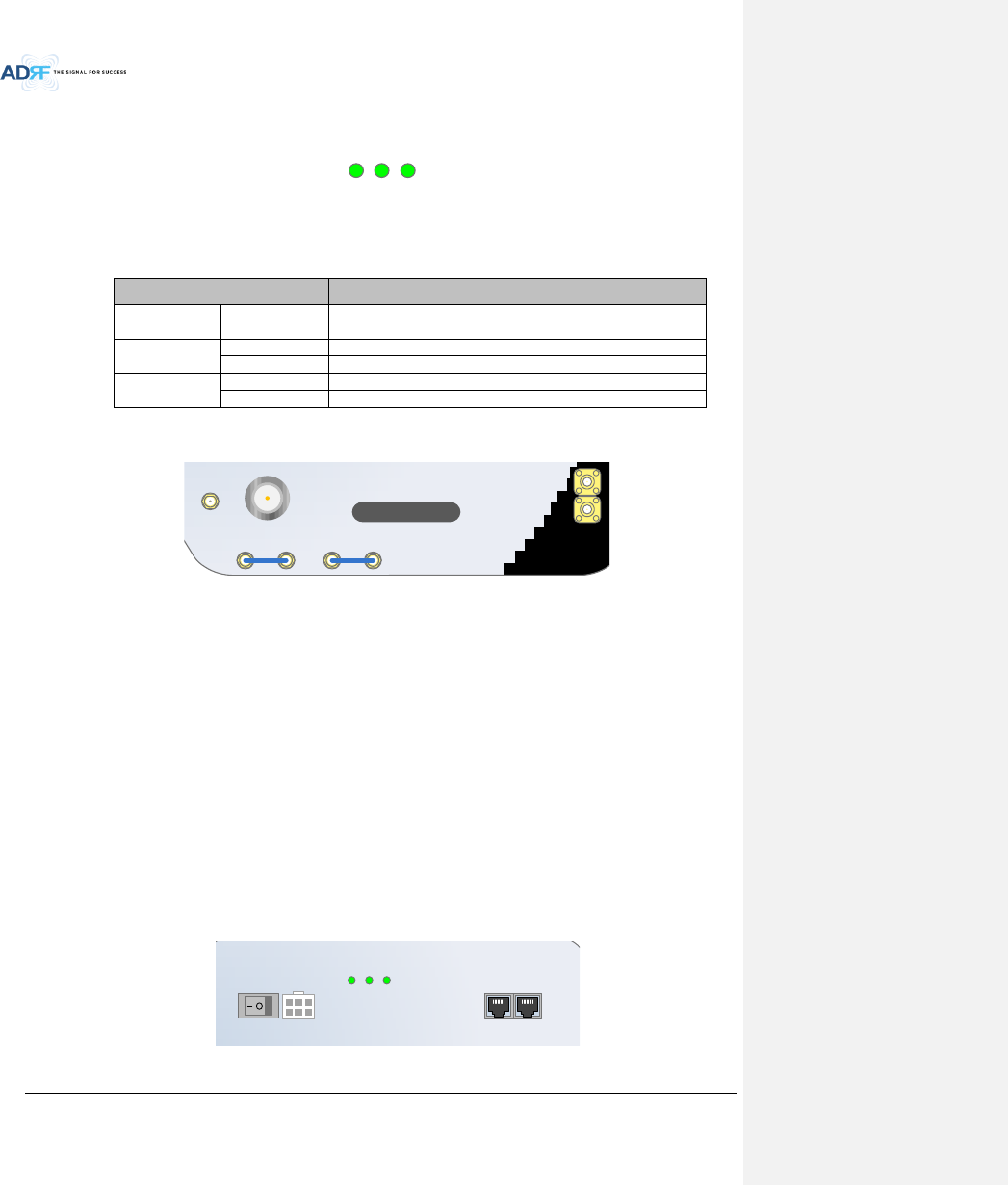
Advanced RF Technologies, Inc.
38
POWER
SOFT-FAIL
HARD-FAIL
Figure 3-29 Slave RU LED
Table 3-5 Slave RU LED Specifications
ADX DAS-Module
Specifications
Power
Solid Green
Module power is ON
OFF
Module power is OFF
Soft Fail
Solid Yellow
Soft Fail alarm exists in the Slave RU
Solid Green
No Soft Fail alarms are present in the Slave RU
Hard Fail
Solid Red
Hard Fail alarm exists in the Slave RU
Solid Green
No Hard Fail alarms are present in the Slave RU
3.2.2.2 RF Ports
Figure 3-30 RF Ports (Slave RU)
3.2.2.2.1 DL IN & UL OUT
Connects to one of the avaialble DL 2 to 4/UL 2 to 4 ports of the Master RU
DL IN port receives the divided DL output from the Master RU
UL OUT port transfers the UL output of slave RU to the Master RU
3.2.2.2.2 SERVER & CPL
Server Port
- Connects directly to a server antenna or the ADX-R-CHC (remote channel combiner)
CPL Port
- 30dB coupling port off of the server port
3.2.2.2.3 EF-DL IN/EF-DL OUT & EF-UL IN/EF- UL OUT
Connect to an external DL/UL filter
DL external filter can be used to reduce out-band emissions
UL external filter can be used to reduce uplink out-band signals
BT and VU RU do not have external filter ports because there are no issues for external filtering
Figure 3-31 Ports at the rear panel (Slave RU)
ADX-R-C30S
DL IN
SERVER
CPL(-30dB)
UL OUT
EF-DL OUT EF-DL IN EF-UL IN EF-UL OUT
DC IN +27VON/OFF
OUT
POWER
SOFT FAIL
HARD FAIL
IN

Advanced RF Technologies, Inc.
39
3.2.2.3 Power On/Off Switch & DC IN Port
Power On/Off switch
- Slave RU Power On/Off switch
DC IN Port
- Connected to DC output port of AC/DC adaptor (ADX-R-ADP-30) or RU PSU (ADX-R-PSU-30)
3.2.2.4 RS-485 Port
Slave RU should be connected to master RU in a diasy chain structure using RS-485 line to monitor and control
slave RUs.
The RS-485 cable connected to master RU should be connected to RS-485 IN port of slave RU. When a slave
RU is connected to another slave RU, then the RS-485 cable should be connected from the RS-485 OUT port to
the RS-485 IN of the 2nd Slave RU. (Figure 3-23)
If RS-485 port connections between Remote Modules are not correct, master RU will not be able to recognize
all subordinate slave RUs. (Figure 3-24)
WARNING! The RS-485 ports should NEVER be connected to the Enthernet port of laptop or Ethernet
Network Equipment. Doing so may cause serious damage to the Remote Modules or network equipments.
(Figure 3-25)
3.2.3 RU Power Supply Options
3.2.3.1 ADX-R-ADP (RU Power Adapter)
The ADX-R-ADP-30 is capable of powering 1 remote module (Master or Slave RU).
3.2.3.2 ADX-R-PSU (RU Power Supply Unit)
ADX-R-PSU-30
POWER
CHG-STS
LOW BATT
AC FAIL
DC FAIL
AC IN
(A=AC_L,B=AC_N,C=F.G)
AC SELECT
BATTERY S/W
BATTERY 24V
PSU ALARM DC OUT
+27V DC OUT
+27V DC OUT
+27V DC OUT
+27V DC OUT
+27V DC OUT
+27V DC OUT
+27V DC OUT
+27V
OFF
OFFOFF
POWER S/W
OFF ON
Figure 3-32 RU PSU Front & Rear View
Functions & Features
- Provides power to 8 remote modules (Master or Slave RU)
- Supports ADRF-BBU Battery Backup
Spec
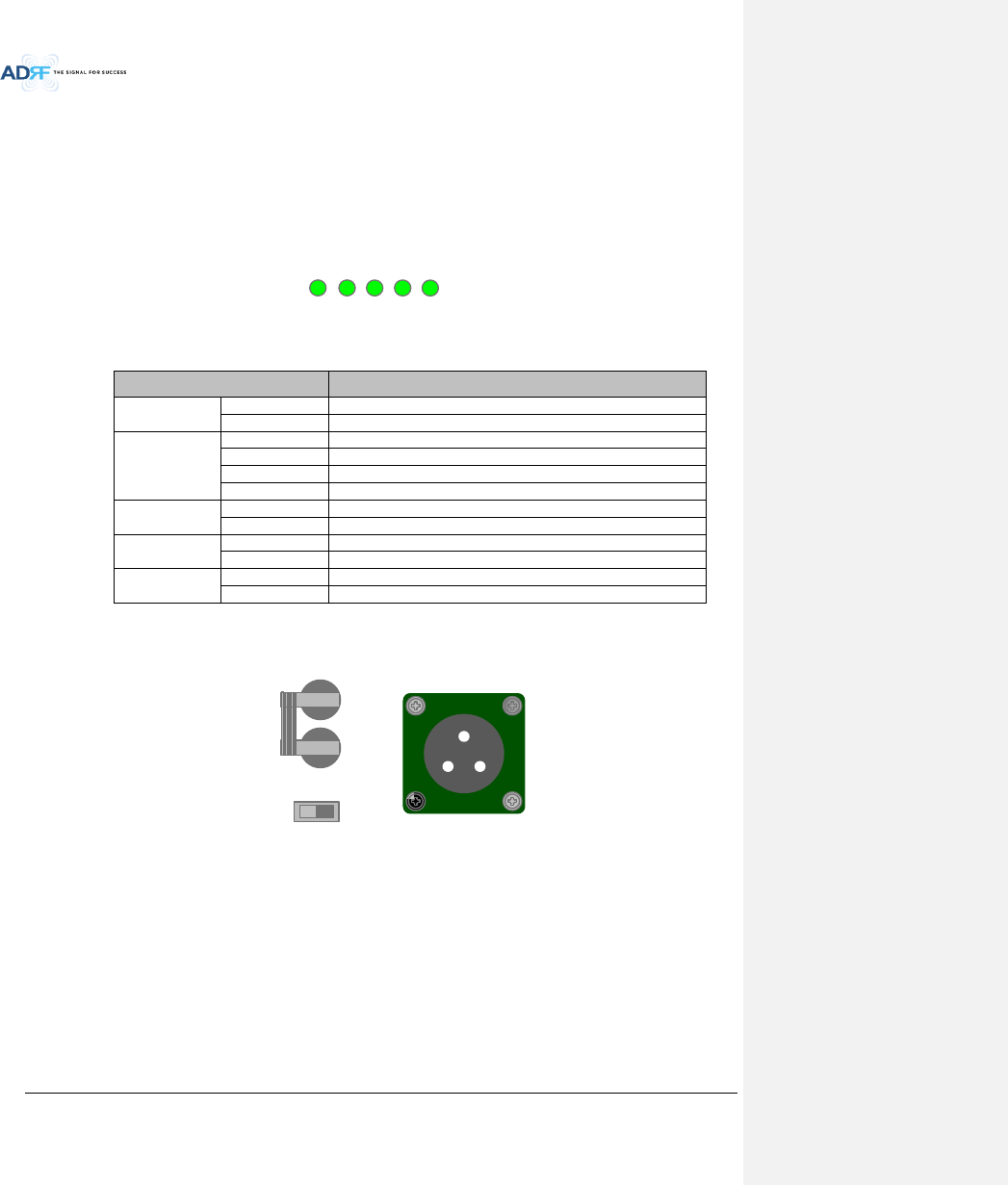
Advanced RF Technologies, Inc.
40
- Size: 19.0 x 12.0 x 2.6 inches (482 x 304x 66 mm)
- Weight: 9.9lbs (4.5 kg)
- Power Input: 110V or 220VAC, selectable by switch
3.2.3.2.1 LEDs
ADX DAS has the following LEDs on the front of the RU PSU as shown below in Figure 3-33.
POWER
CHG STS
LOW BATT
AC FAIL
DC FAIL
Figure 3-33 RU PSU LED
Table 3-6 RU PSU LED Specifications
ADX DAS-Module
Specifications
Power
Solid Green
Module power is ON
OFF
Module power is OFF
CHG STS
Solid Yellow
No AC power detected and ADRF-BBU is being used
Blinking Green
ADRF-BBU is being charged
Solid Green
Completely Charged
OFF
Battery is not connected
LOW BATT
Solid Yellow
Low Battery alarm exist in the PSU
Solid Green
No Low Battery alarm is present in the PSU
AC FAIL
Solid Yellow
AC Fail alarm exist in the PSU
Solid Green
No AC Fail alarm is present in the PSU
DC FAIL
Solid Yellow
DC Fail alarm exist in the RFU
Solid Green
No DC Fail alarms is present in the PSU
3.2.3.2.2 AC Input On/Off Switch, AC Input Port and AC Input Selection Switch
AC IN
(A=AC_L,B=AC_N,C=F.G)
AC SELECT
OFFOFF
POWER S/W
Figure 3-34 RU PSU Power Switch View
The AC Power on/off switch is located at the rear of the ADX-R-PSU-30. The ADX-R-PSU-30 can be operated at
the 110V AC or 220V AC. The AC Input Voltage should be properly set by the user.
3.2.3.2.3 Battery Backup Port and Battery Backup Switch
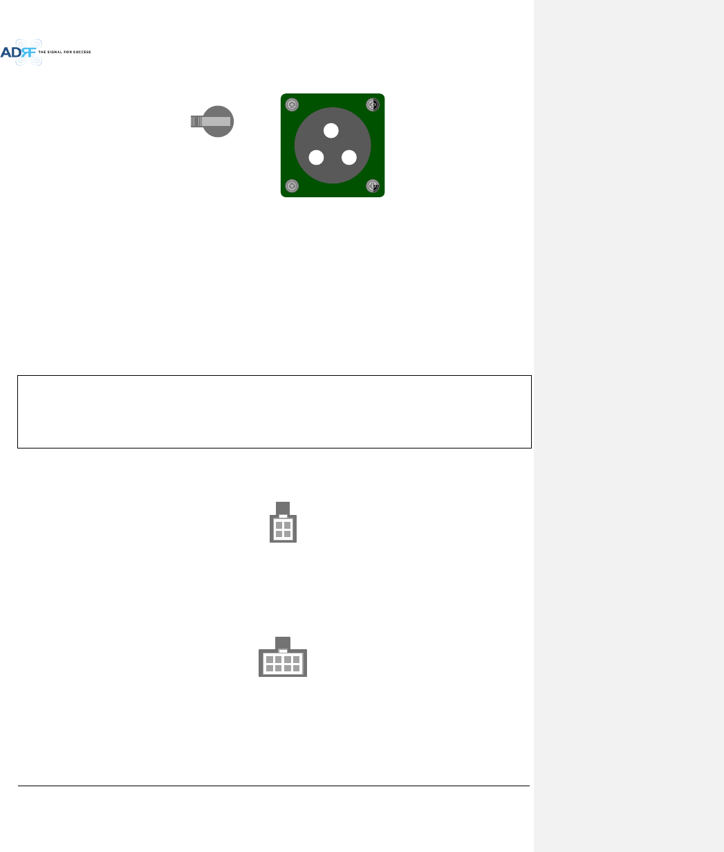
Advanced RF Technologies, Inc.
41
BATTERY S/W
BATTERY 24V
OFF
OFF ON
Figure 3-35 Battery Backup Port & Battery Backup Switch
When the Battery S/W is set to the ON position, the power supply charges the optional ADRF-BBU (External
Backup Battery) (Figure 3-35).
The RU PSU can be connected to an ADRF-BBU (ADRF Battery Backup Unit) to provide power during a power
failure. If an ADRF-BBU is utilized, connect the ADRF-BBU to the RU PSU via the external battery backup port as
shown in Figure 3-35.
(WARNING: The circuit switch on the ADRF-BBU must be set to OFF before connecting the ADRF-BBU to the
HE PSU to prevent damage to the HE PSU or the ADRF-BBU and personal injury.)
Note: Please contact ADRF Technical Support for assistance if you are unfamiliar with the installation
procedure of our battery box.
The procedure for connecting RU PSU to BBU
BATT S/W OFF
Connect BBU to RU PSU Battery port using RU battery cable
BATT S/W ON
3.2.3.2.4 DC Output Port
DC OUT
+27V
Figure 3-36 DC Output Port (RU PSU)
(8) DC output ports are available to connect up to 8 remote modules (Master or Salve RU’s)
3.2.3.2.5 PSU Alarm Port
PSU ALARM
Figure 3-37 PSU Alarm Port (RU PSU)
Connects to the Master RU to monitor the status of the ADX-R-PSU-30
The ADX-H-NMS & Master RU monitor the status of the ADX-R-PSU-30 via this port
4. CABLE CONNECTION
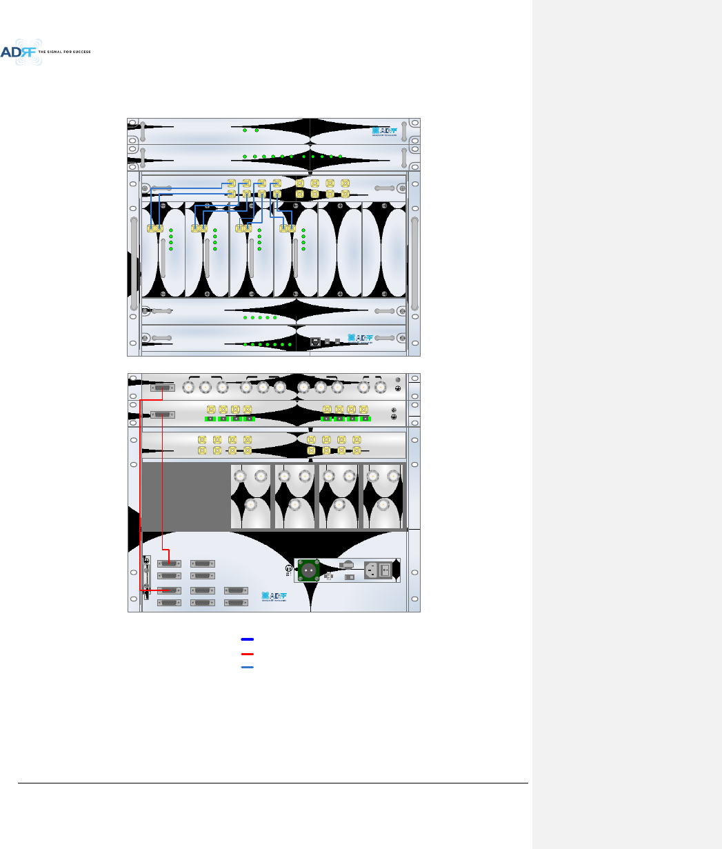
Advanced RF Technologies, Inc.
42
4.1 Head End Connection Diagrams
4.1.1 Front/Rear Head End Connection View with Optional BCU unit
ADX-H-NMS
POWER
SOFT FAIL-H
SOFT FAIL-R
HARD FAIL-H
HARD FAIL-R
LINK FAIL-H
LINK FAIL-R
HOST HE VIEW
REMOTE RU VIEW
ADX-H-PSU
POWER
CHG STS
LOW BATT
AC FAIL
DC FAIL
DL OUTUL IN
HARD FAIL
DL SIG LOW
SOFT FAIL
POWER
ADX-H-RFU-P
DL OUTUL IN
HARD FAIL
DL SIG LOW
SOFT FAIL
POWER
ADX-H-RFU-7
DL OUTUL IN
HARD FAIL
DL SIG LOW
SOFT FAIL
POWER
ADX-H-RFU-C
DL OUTUL IN
HARD FAIL
DL SIG LOW
SOFT FAIL
POWER
ADX-H-RFU-A
ADX-H-CHC
UL1 UL2 UL3 UL4
DL1 DL2 DL3 DL4
UL5 UL6 UL7 UL8
DL5 DL6 DL7 DL8
LD FAIL5-8 LINK5 LINK6 LINK7 LINK8LD FAIL1-4 LINK1 LINK2 LINK3 LINK4POWER
ADX-H-OPT
SOFT FAILPOWER
ADX-H-BCU-P
Figure 4-1 HE Cable connection (1 OPT-8 +1 BCU)
VHF UL 2 UL OUT 2 VHF DL 2 DL IN 2
LINK 8 LINK 7 LINK 6 LINK 5
VHF UL 1 UL OUT 1 VHF DL 1 DL IN 1
LINK 4 LINK 3 LINK 2 LINK 1
OPT
DL IN UL OUT
DPX
ADX-H-RFU-P
DL IN UL OUT
DPX
ADX-H-RFU-7
DL IN UL OUT
DPX
ADX-H-RFU-C
DL IN UL OUT
DPX
ADX-H-RFU-A
UL5UL6UL7UL8
DL5DL6DL7DL8
UL1UL2UL3UL4
DL1DL2DL3DL4
OPT 1 OPT 2
OPT 3 OPT 4
BAND COM 1 BAND COM 2
BAND COM 3 BAND COM 4
AUX_CH 1
AUX_CH 2
DL IN 3
BAND COM
CH3 CH2 CH1 SUM
DPX 3 UL OUT 3 DL IN 2 DPX 2 UL OUT 2 DL IN 1 DPX 1 UL OUT 1 DL OUT UL IN
BATTERY
INSTALL
BATTERY
BATTERY
AC SELECT OFF/ONAC IN
OFF
S/WOFF ON
24V 1A
RS485
Power & Signal
RF
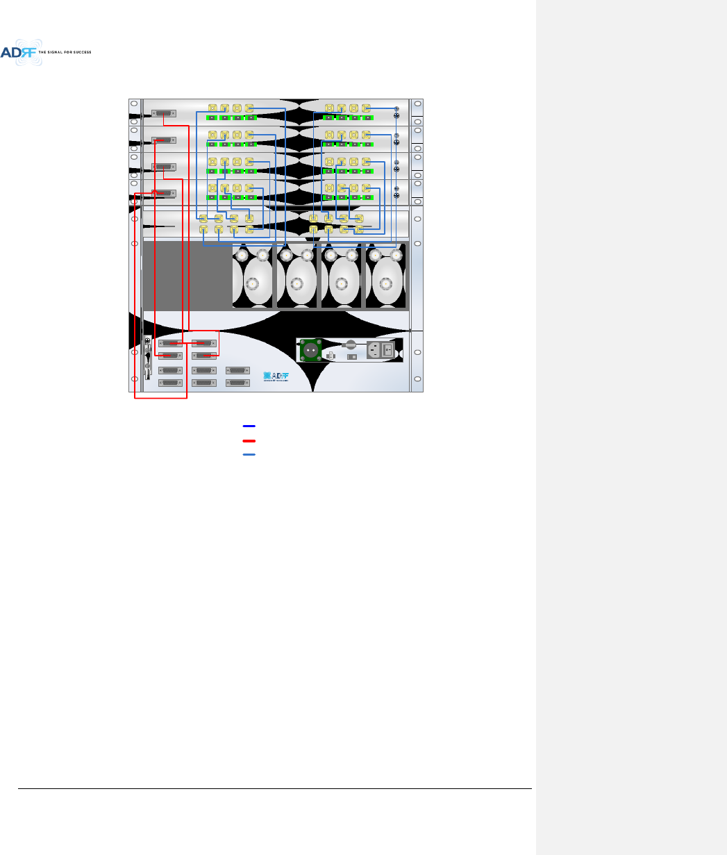
Advanced RF Technologies, Inc.
43
4.1.2 Rear Head End Connection View with (4) OPT-8 units
Figure 4-2 HE Cable connection (4 OPTs)
DL IN UL OUT
DPX
ADX-H-RFU-P
DL IN UL OUT
DPX
ADX-H-RFU-7
DL IN UL OUT
DPX
ADX-H-RFU-C
DL IN UL OUT
DPX
ADX-H-RFU-A
UL5UL6UL7UL8
DL5DL6DL7DL8
UL1UL2UL3UL4
DL1DL2DL3DL4
OPT 1 OPT 2
OPT 3 OPT 4
BAND COM 1 BAND COM 2
BAND COM 3 BAND COM 4
AUX_CH 1
AUX_CH 2
VHF UL 2 UL OUT 2 VHF DL 2 DL IN 2
LINK 8 LINK 7 LINK 6 LINK 5
VHF UL 1 UL OUT 1 VHF DL 1 DL IN 1
LINK 4 LINK 3 LINK 2 LINK 1
OPT
VHF UL 2 UL OUT 2 VHF DL 2 DL IN 2
LINK 8 LINK 7 LINK 6 LINK 5
VHF UL 1 UL OUT 1 VHF DL 1 DL IN 1
LINK 4 LINK 3 LINK 2 LINK 1
OPT
VHF UL 2 UL OUT 2 VHF DL 2 DL IN 2
LINK 8 LINK 7 LINK 6 LINK 5
VHF UL 1 UL OUT 1 VHF DL 1 DL IN 1
LINK 4 LINK 3 LINK 2 LINK 1
OPT
VHF UL 2 UL OUT 2 VHF DL 2 DL IN 2
LINK 8 LINK 7 LINK 6 LINK 5
VHF UL 1 UL OUT 1 VHF DL 1 DL IN 1
LINK 4 LINK 3 LINK 2 LINK 1
OPT
OFF
BATTERY
INSTALL
BATTERY
BATTERY
AC SELECT OFF/ONAC IN
S/WOFF ON
24V 1A
RS485
Power & Signal
RF
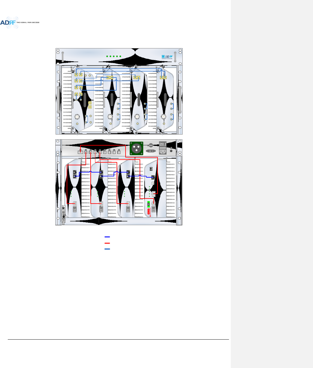
Advanced RF Technologies, Inc.
44
4.2 Remote Unit Connection Diagrams
Figure 4-3 RU Cable connection (4 Remote Module + RU PSU)
ADX-R-PSU-30
POWER
CHG-STS
LOW BATT
AC FAIL
DC FAIL
ADX-R-730S
DL IN
SERVER
CPL(-30dB)
UL OUT
EF-DL OUT EF-DL IN EF-UL IN EF-UL OUT
ADX-R-C30S
DL IN
SERVER
CPL(-30dB)
UL OUT
EF-DL OUT EF-DL IN EF-UL IN EF-UL OUT
ADX-R-A30S
DL IN
SERVER
CPL(-30dB)
UL OUT
EF-DL OUT EF-DL IN EF-UL IN EF-UL OUT
SERVER
UL1 UL2 UL3 UL4
ADX-R-P30M
DL1 DL2 DL3 DL4
M-DL
M-UL
CPL(-30dB)
E-DL
E-UL
VHF DL VHF UL
EF-DL IN EF-DL OUT
EF-UL INEF-UL OUT
AC IN
ON / OFF
AC SELECT
BATTERY S/W
BATTERY 24V
PSU ALARM DC OUT
+27V DC OUT
+27V DC OUT
+27V DC OUT
+27V DC OUT
+27V DC OUT
+27V DC OUT
+27V DC OUT
+27V
OFF
DC IN +27VON/OFF
OUT
POWER
SOFT FAIL
HARD FAIL
IN
DC IN +27VON/OFF
OUT
POWER
SOFT FAIL
HARD FAIL
IN
DC IN +27VON/OFF
OUT
POWER
SOFT FAIL
HARD FAIL
IN
POWER
SOFT FAIL
HARD FAIL
COMM
OPTIC FAIL
DC IN +27V PSU ALARM RS-485GUI
OPTIC
ON/OFF
ON
1 2 3 4
ADDR
DANGER
RS485
Power & Signal
RF
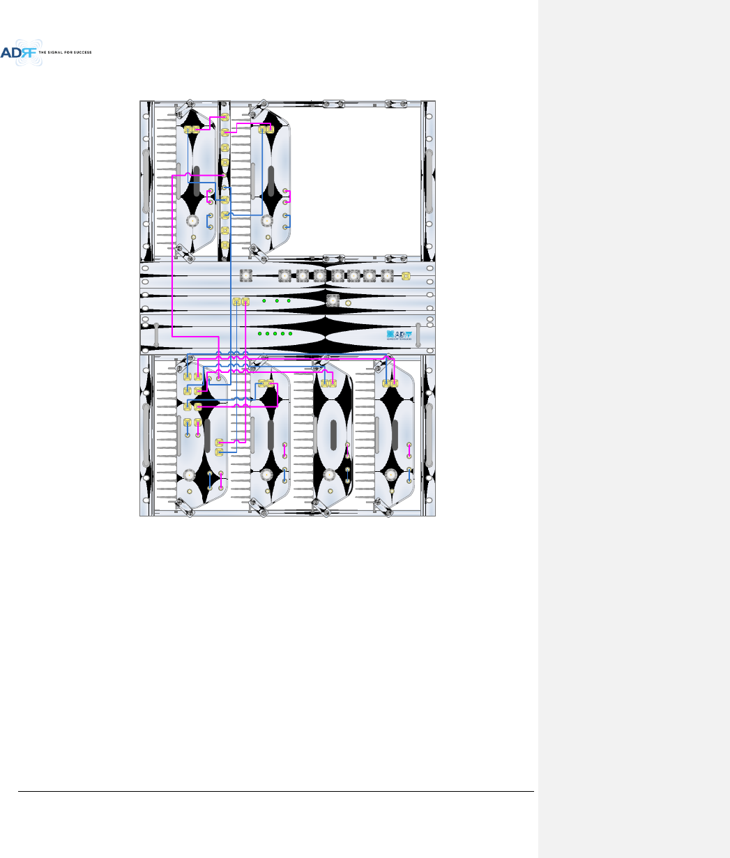
Advanced RF Technologies, Inc.
45
4.3 Remote Unit w/ 4-Way Combiner (ADX-R-4WS)
Figure 4-4 Slave RU Expansion using ADX-R-4WS
SERVER
UL1 UL2 UL3 UL4
ADX-R-P30M
DL1 DL2 DL3 DL4
M-DL
M-UL
CPL(-30dB)
E-DL
E-UL
VHF DL VHF UL
EF-DL IN EF-DL OUT
EF-UL INEF-UL OUT
ADX-R-730S
DL IN
SERVER
CPL(-30dB)
UL OUT
EF-DL OUT EF-DL IN EF-UL IN EF-UL OUT
DL4 DL3 DL2 DL1 ADX-R-4WS UL4 UL3 UL2 UL1
M-ULM-DL
ADX-R-730S
DL IN
SERVER
CPL(-30dB)
UL OUT
EF-DL OUT EF-DL IN EF-UL IN EF-UL OUT
ADX-R-PSU-30
POWER
CHG-STS
LOW BATT
AC FAIL
DC FAIL
ADX-R-730S
DL IN
SERVER
CPL(-30dB)
UL OUT
EF-DL OUT EF-DL IN EF-UL IN EF-UL OUT
ADX-R-C30S
DL IN
SERVER
CPL(-30dB)
UL OUT
EF-DL OUT EF-DL IN EF-UL IN EF-UL OUT
ADX-R-A30S
DL IN
SERVER
CPL(-30dB)
UL OUT
EF-DL OUT EF-DL IN EF-UL IN EF-UL OUT
WiMAXCellularSMR800AWS700MPCS
COM WIFI
SMR900
ADX-R-CHC
POWER SOFT FAIL HARD FAIL
DL-IN UL-OUT MON
SERVER
ADX-R-V30S