ADRF KOREA FIRE-78-4 Repeater User Manual FiRe 78 4 Installation and Operating Manual
ADRF KOREA, Inc. Repeater FiRe 78 4 Installation and Operating Manual
UserManual.wiki
>
ADRF KOREA
>
FIRE 78 4 User Manual
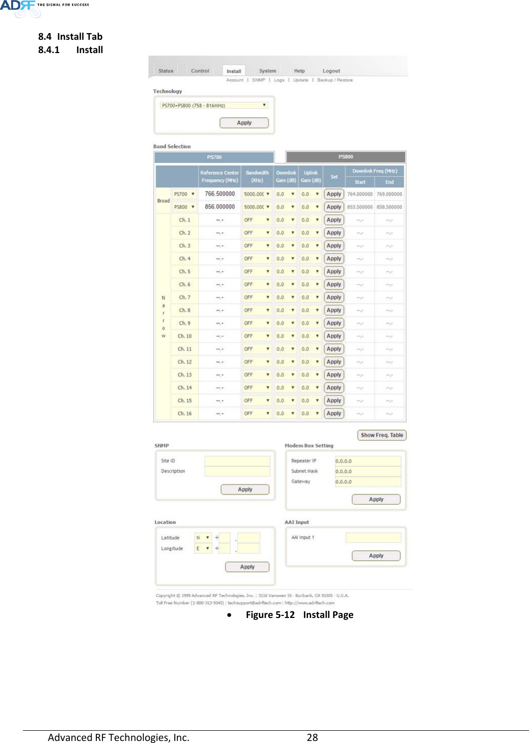
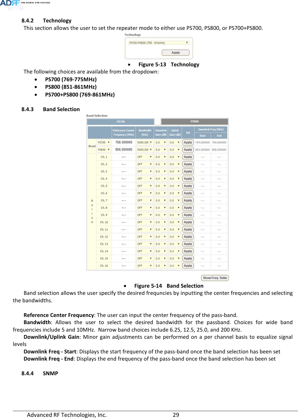
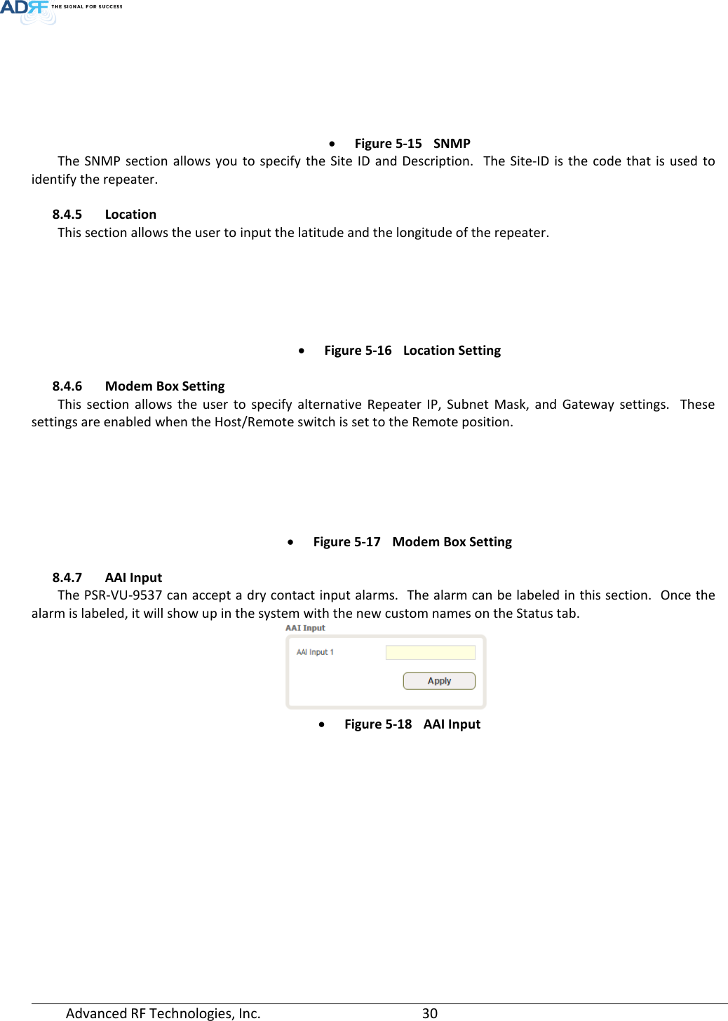
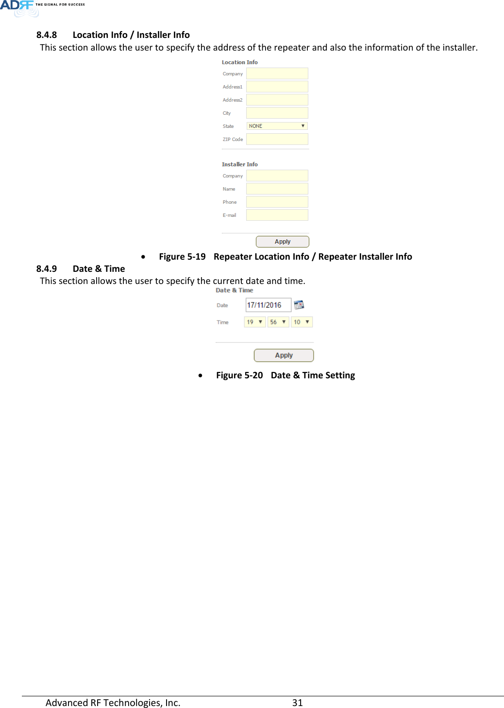
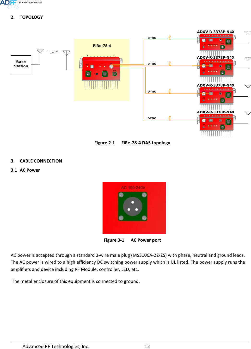
FiRe-78-4 Installation User Manual v0.2 (2018.01.09)_Rev.1
Navigation menu
Upload a User Manual
Namespaces
Wiki Guide
HTML
PDF
Info
Views
User Manual
Discussion / Help
Navigation
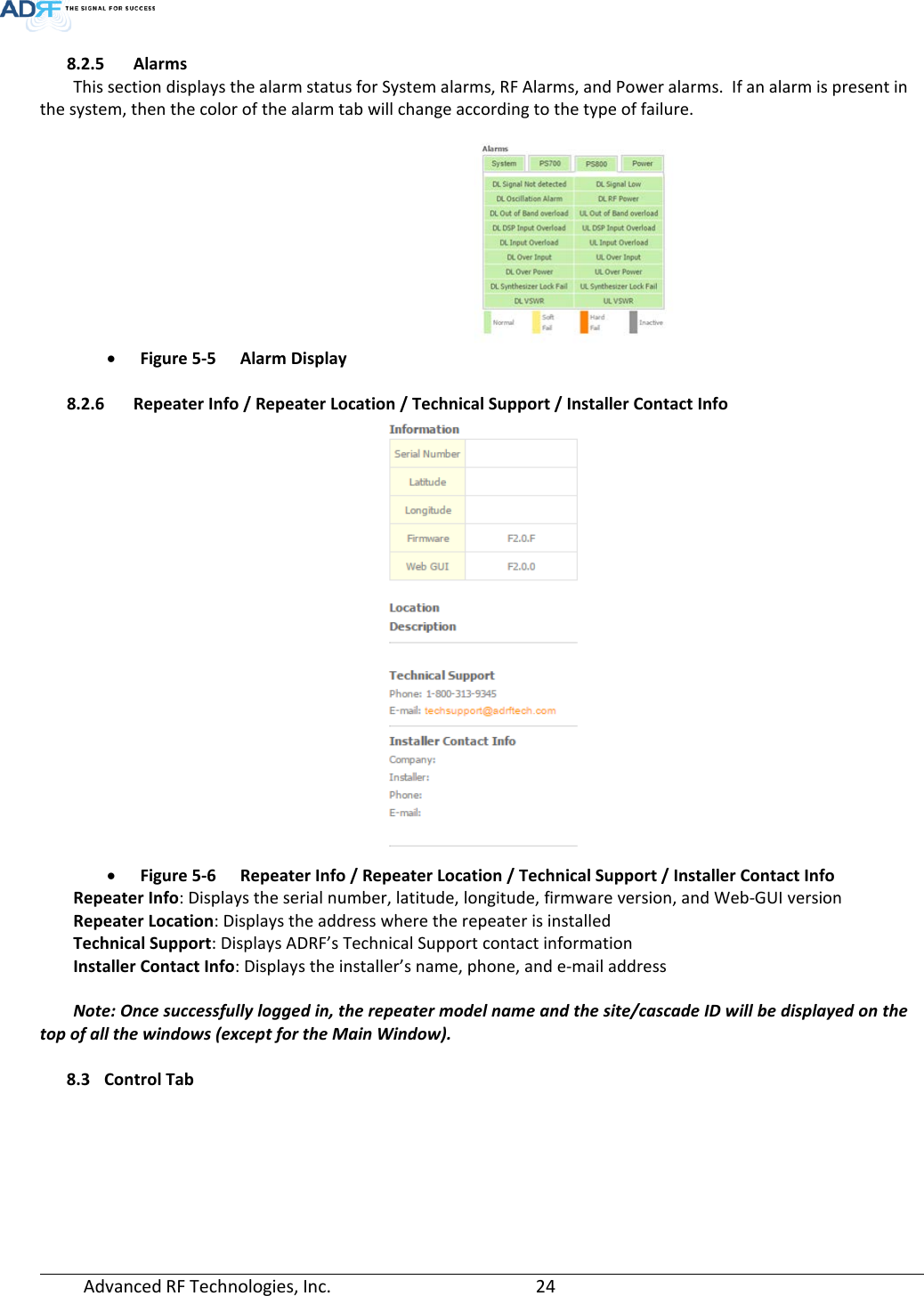
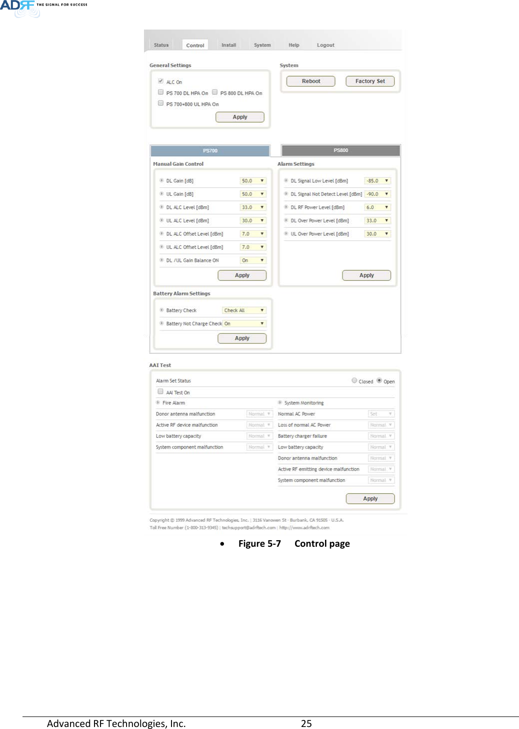
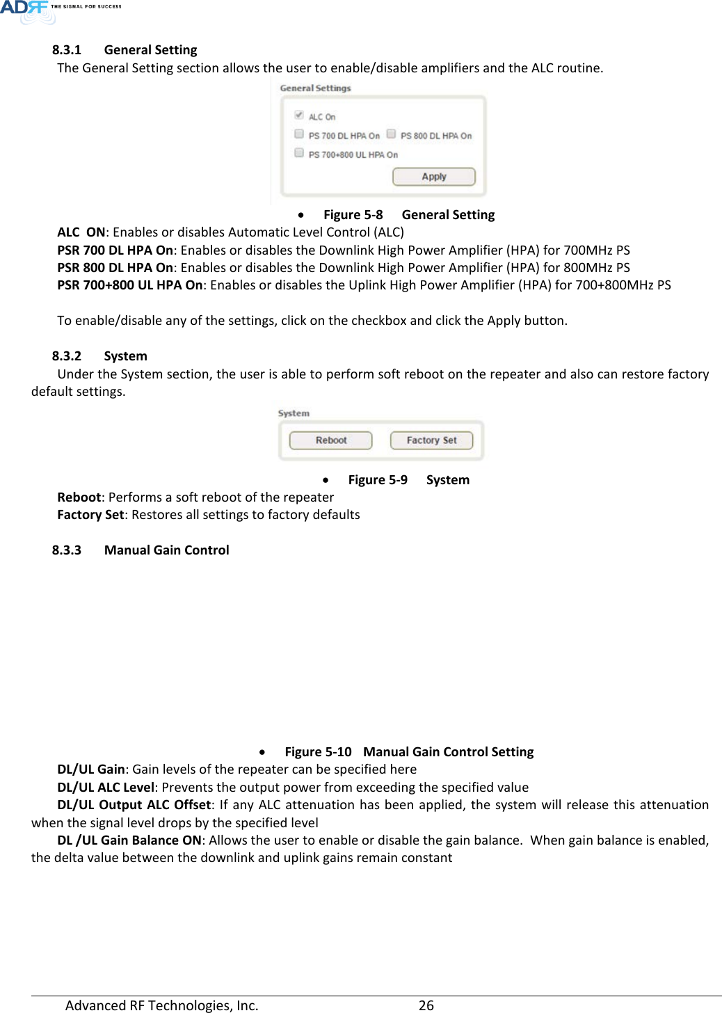
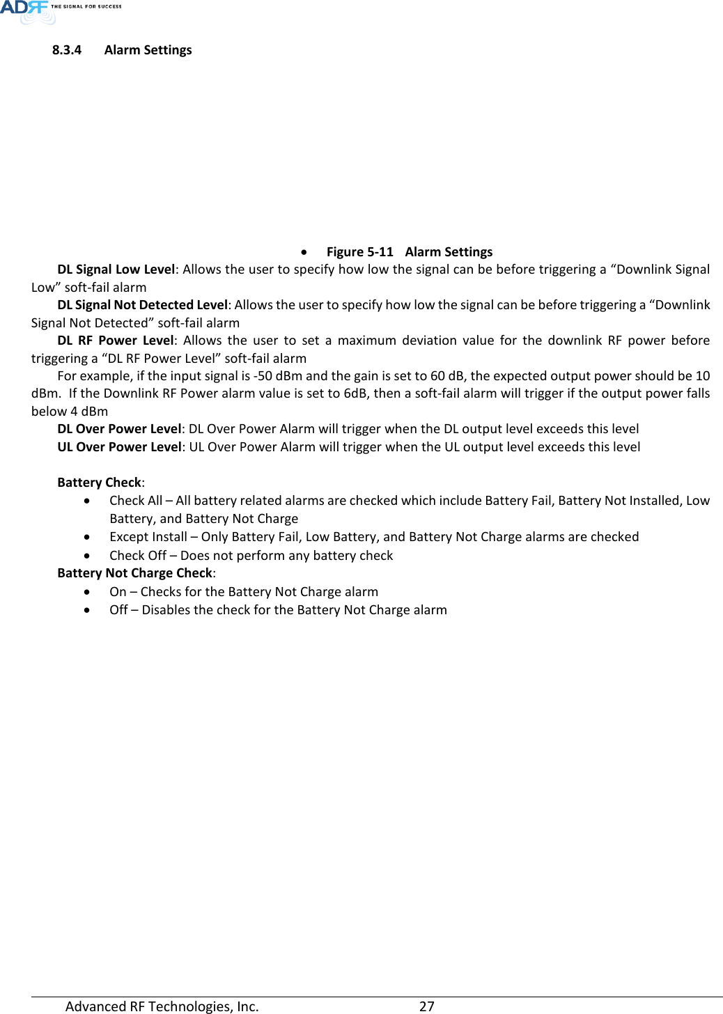
![Advanced RF Technologies, Inc. 18 7.1 Electrical Specifications Parameters Specifications Remarks DL UL Frequency Range (MHz) PS 700 769 - 775MHz(For FCC) (768-769MHz Guard band) 768 - 775 MHz (For ISED) 799 - 805 MHz(For FCC) (798- 799MHz Guard band) 798- 805 MHz (For ISED) PS 800 851 - 861 806 - 816 Composite Output Power of FiRe-78-4 PS 700 -24dBm 30dBm PS 800 -24dBm 30dBm PS 700 + PS 800 -24dBm 30dBm Composite Output Power of FiRe-78-4+ADXV-R-78PS PS 700 33dBm 30dBm PS 800 33dBm 30dBm System total Gain (dB) [FiRe-78-4+ ADXV-R-3378P-N4X] 95 85 System total Input power [FiRe-78-4+ADXV-R-3378P-N4X] -62dBm -55dBm Filter selection Narrow Simultaneous Filter Support numbers Narrow Band Up to 16(Non-contiguous) @ PS 700 / PS 800 Up to 32(Non-contiguous) @ PS 700 + PS 800 Narrow(kHz) 6.25, 12.5, 25 Narrow(kHz) ≥ 60dBc@Filter Bandwidth Edge + 3 x Filter BW Spurious FCC Rule Compliant Passband Ripple ±2 dB ALC Dynamic Range ≥ 60dB DL Path Only Gain Dynamic Range ≥ 40dB Channel Setting Resolution 0.025 kHz System Group Delay Broad Band <6.5us Except of optic cable delay, Except of ADXV-R-3378P-N4X Narrow Band ≤85us@6.25KHz_BW ≤46us@12.5KHz_BW ≤28us@25KHz _BW Power Supply 100 -240 VAC, 60Hz (Free Voltage) With battery backup, Power Consumption <135Watt Max RF Input Power without over drive -20dBm UL Noise Figure @ Max. Gain 5.0dB Center Frequency [ADXV-R-3378P-N4X+ FiRe-78-4] No damage Max Input Power +10dBm DL Path Only Enclosure Cooling Natural Convection Impedance 50 Ω VSWR <1.5 : 1 DL/UL Input ODU number per NEMA4-x 1 ODUs(; max 4 RUs) Dry Contacts NFPA 72 2016 Code Compliant Remote Alarming / Network Management Dry Contacts, Web-GUI, SNMP, SNMP-Traps (External Wireless Modem Required) Relative Humidity 5% - 90% Operating Temperature -40°F to +140°F (-40°C to +60°C) NFPA 1221 2016 Code Compliancy Compliant](https://usermanual.wiki/ADRF-KOREA/FIRE-78-4/User-Guide-3738026-Page-18.png)
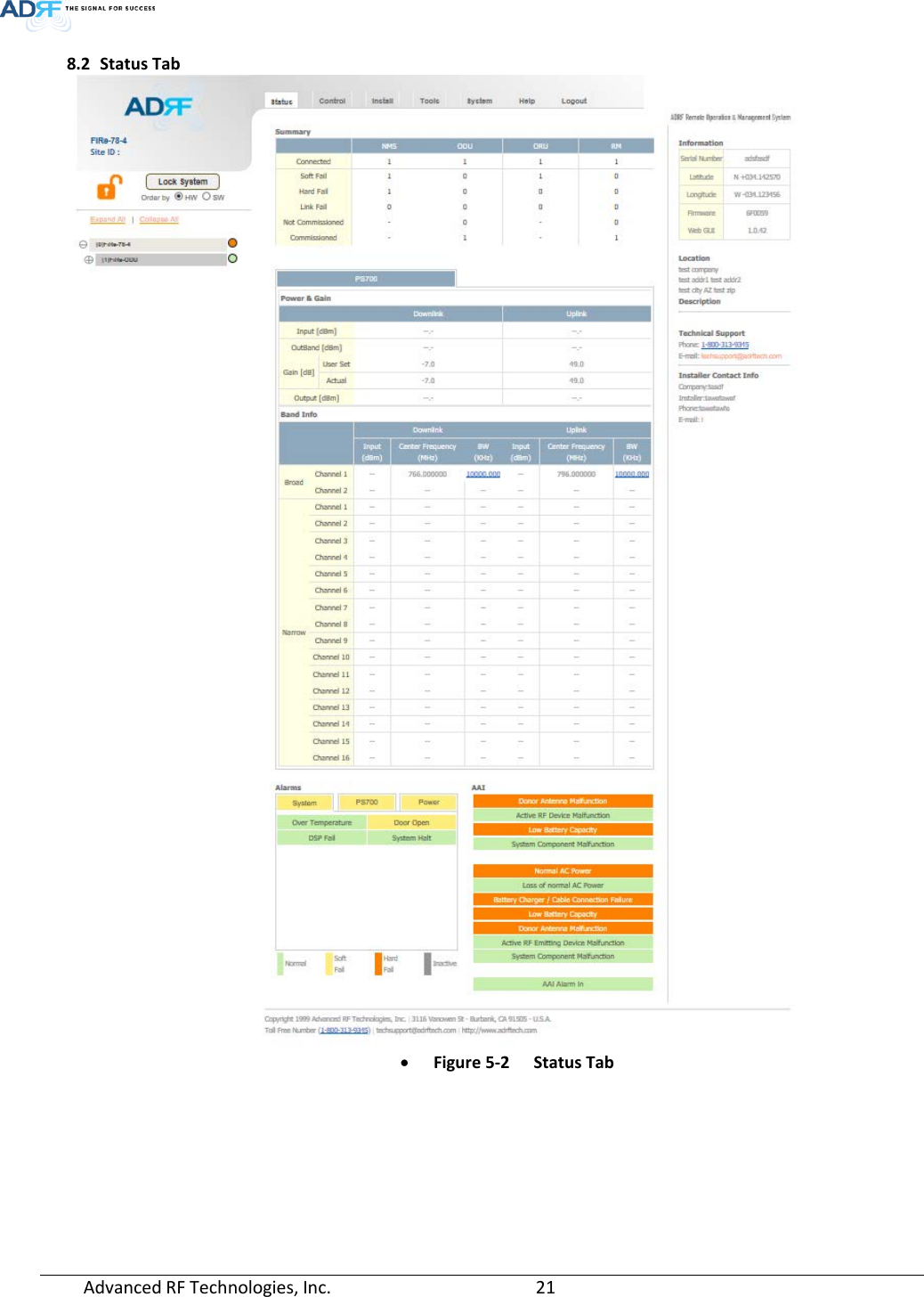
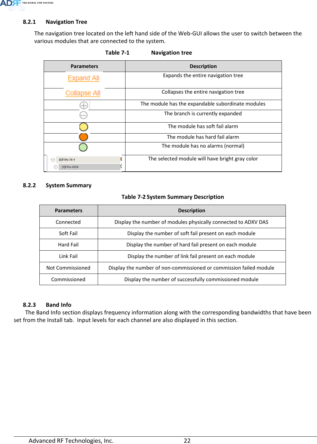
![Advanced RF Technologies, Inc. 23 • Figure 5-3 Band Info Display 8.2.4 Power & Gain This section displays the Input, Gain, and Output for both downlink and uplink. • Figure 5-4 Power & Gain Display Input [dBm] – Displays the in-band Downlink/Uplink signal level. The system will display “--.-“ when the input level is < -90 dBm. Outband [dBm] – Displays the out-band composite power. Gain [dB] User Set: Displays the amount of gain that the user set. Actual: Displays the actual amount of gain that is currently in use. Output [dB] – Displays the Downlink/Uplink composite output power levels. The system will display “--.-“, when the output level is < +5 dBm.](https://usermanual.wiki/ADRF-KOREA/FIRE-78-4/User-Guide-3738026-Page-23.png)