ADRF KOREA FIRE-78-4 Repeater User Manual FiRe 78 4 Installation and Operating Manual
ADRF KOREA, Inc. Repeater FiRe 78 4 Installation and Operating Manual
FiRe-78-4 Installation User Manual v0.2 (2018.01.09)_Rev.1


Advanced RF Technologies, Inc.
ii
Information in this document is subject to change without notice.
Advanced RF Technologies, Inc. 1996-2015.
All rights reserved.
• Please send comments to:
E-Mail: info@adrftech.com
Phone: (818) 840-8131
(800) 313-9345
Fax: (818) 840-8138
• Address:
Advanced RF Technologies, Inc.
Attention: Technical Publications Department
3116 Vanowen St.
Burbank, CA 91505
USA
www.adrftech.com
Advanced RF Technologies, Inc.
iii
Revision History
Change List
Version Change list Contents
Version Author Descriptions Date
0.1
YH Ko
Initial Release
2017/11/17
0.2
CK CHO
Update
2018/01/09

Advanced RF Technologies, Inc.
iv
Table of Contents
1. Introduction ........................................................................................................................................................ 6
1.1 Highlights ..................................................................................................................................................... 6
1.2 Quick View ................................................................................................................................................... 7
1.3 Warnings and Hazards ................................................................................................................................. 8
2. Topology ........................................................................................................................................................... 12
3. Cable Connection .............................................................................................................................................. 12
3.1 AC Power ................................................................................................................................................... 12
3.2 External Alarm ........................................................................................................................................... 13
3.3 RF ............................................................................................................................................................... 13
3.4 Optic .......................................................................................................................................................... 14
3.5 Battery ....................................................................................................................................................... 15
3.6 Grounding .................................................................................................................................................. 15
4. RF EXPOSURE WARNING ................................................................................................................................... 16
5. Installation ........................................................................................................................................................ 17
6. default items ..................................................................................................................................................... 17
7. Specifications .................................................................................................................................................... 17
7.1 Electrical Specifications ............................................................................................................................. 18
7.2 Mechanical Specifications.......................................................................................................................... 19
Figures
Figure 1-1 FiRe-78-4 Quick View (front and bottom) ............................................................................................ 7
Figure 2-1 FiRe-78-4 DAS topology ...................................................................................................................... 12
Figure 3-1 AC Power port..................................................................................................................................... 12
Figure 3-2 External Alarm port ............................................................................................................................ 13
Figure 3-3 RF port ................................................................................................................................................ 13
Figure 3-4 Optic port............................................................................................................................................ 14
Figure 3-5 Optic Connector Cleaning (left) and Optic Port Cleaning (right) ........................................................ 14
Figure 3-6 SC/APC Optic Connector Dust Cap ..................................................................................................... 15
Figure 3-7 Protective Earthing Conductor ........................................................................................................... 16

Advanced RF Technologies, Inc.
5
Terms and Abbreviations
The following is a list of abbreviations and terms used throughout this document.
Abbreviation/Term Definition
AGC Automatic Gain Control
ALC Automatic Level Control
AROMS ADRF’ Repeater Operation and Management System
BCU Band Combiner Unit
BTS Base Transceiver Station
BDA Bi-directional Amplifier
CDMA Code Division Multiple Access
CHC Channel combiner
CW Continuous Wave (un-modulated signal)
DAS Distributed Antenna System
DL Downlink
Downlink The path covered from the Base Transceiver Station (BTS) to the subscribers’ service area
via the repeater
HE Head End
HPA High Power Amplifier
HW Hardware
IF Intermediate Frequency
LNA Low Noise Amplifier
LTE Long Term Evolution
MS Mobile Station
NMS Network Management System
ODU Optical Donor Unit which is located in ADXV-HE.
OEU Optic Expansion Unit
PLL Phased Locked Loop
POI Point Of Interface
PSU Power Supply Unit
RF Radio Frequency
RU Remote Unit which is composed of master RU and multiple slaves RU
RM Remote Module
SW Software
UL Uplink
Uplink The path covered from the subscribers’ service area to the Base Transceiver Station (BTS)
via the repeater
VSWR Voltage Standing Wave Ratio

Advanced RF Technologies, Inc.
6
1. INTRODUCTION
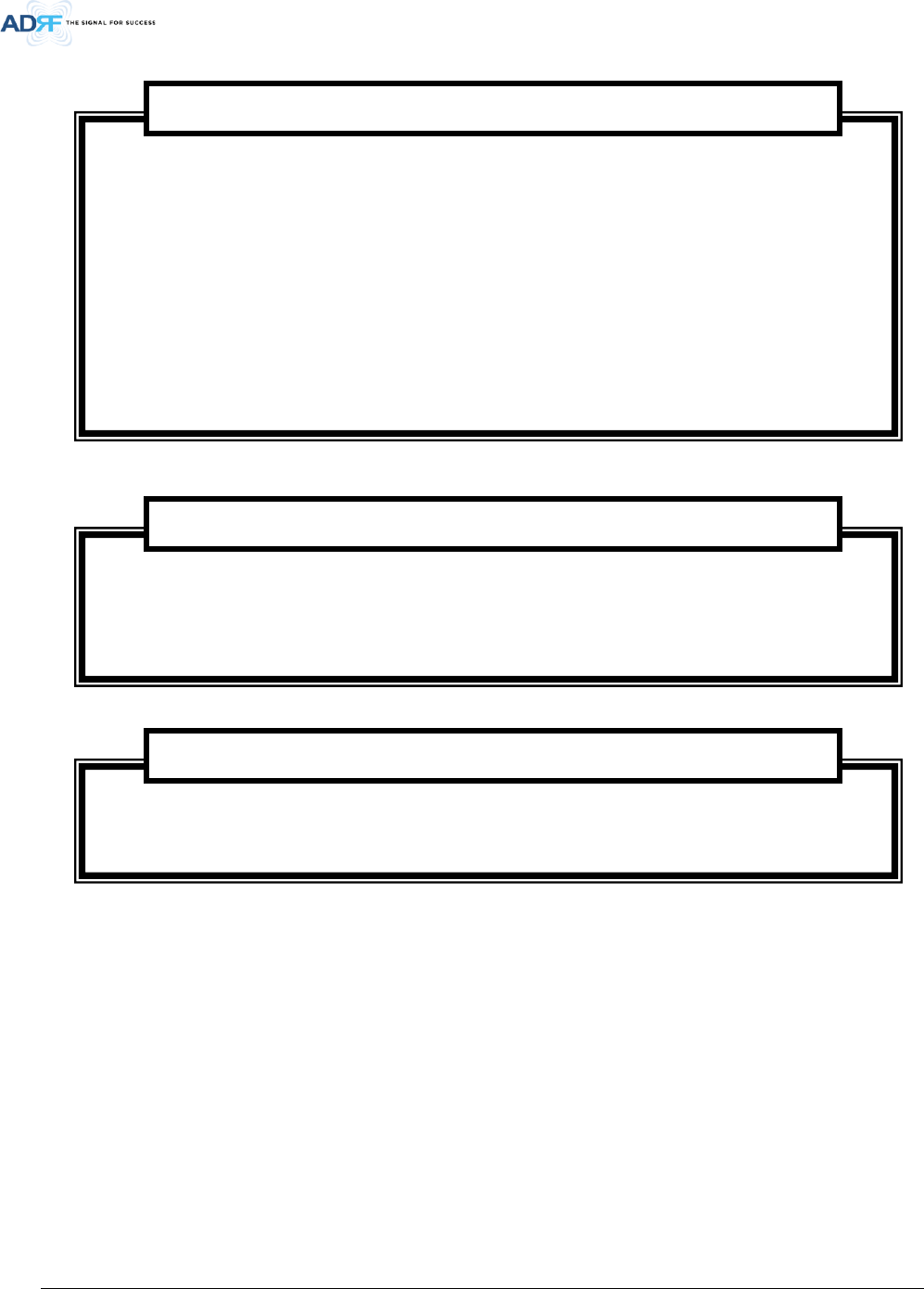
FiRe-78-4 which is the wireless Head end of Distributed Antenna System for VHF/UHF band has roles which interfaces
with Base Station via wireless and optically distributes by connection with multiple ADXV-R-3378P-N4X, which is one
of the ADRF’s DAS product lineups, via optic lines.
1.1 Highlights
• Head end supporting 700MHz, 800MHz and Public Safety service band of DAS connected through optic line to
ADXV-R-3378P-N4X playing a role of Remote unit of DAS for 700/800MHz/Public Safety band
• Fanless
• Supports a total of 2 wide band and up to 32 non-contiguous narrow band channels (700MHz + 800MHz PS)
• Air convection cooling without fans
• Sharp Filter Roll-off performance (Wide: 60dBc @ Filter Bandwidth Edge + 1MHz | Narrow: 55dBc @ Filter
Bandwidth Edge + 3 * Filter BW)
• Supports SNMP v1, v2c, v3 (get, set, & traps)
• Web-based GUI Interface; No 3rd party GUI software required
• Web-GUI connectivity via DHCP in host mode
• External Alarm Function supporting dry contacts, 11 outputs and 1 input

Advanced RF Technologies, Inc.
7
1.2 Quick View
Figure 1-1 FiRe-78-4 Quick View (front and bottom)
Advanced RF Technologies, Inc.
8
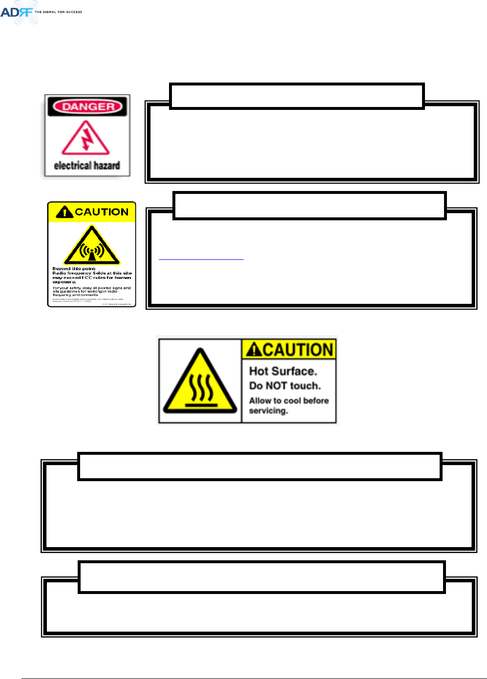
1.3 Warnings and Hazards
Opening the PSR-VU-9537 could result in electric shock and may cause
severe injury.
WARNING!
ELECTRIC
SHOCK
Working with the PSR-VU-9537 while in operation, may expose the technician to RF
electromagnetic fields that exceed FCC rules for human exposure. Visit the FCC website at
www.fcc.gov/oet/rfsafety to learn more about the effects of exposure to RF electromagnetic
fields.
WARNING! EXPOSURE TO RF
Actual separation distance is determined upon gain of antenna used.
Please maintain a minimum safe distance of at least 200 cm while operating near the donor and
the server antennas.
RF EXPOSURE & ANTENNA PLACEMENT Guidelines
Opening or tampering the FiRe -78-4 will void all warranties.
WARRANTY
Advanced RF Technologies, Inc.
9
This device is only for Class A. According to FCC/ISED requirement, the passband of a Class B booster (except for
DAS boosters installed in buildings) should not encompass CMRS along with part 90 PLMRS and/or PSRS.
Lithium Battery: CAUTION. RISK OF EXPLOSION IF BATTERY IS REPLACED BY INCORRECT TYPE.
DISPOSE OF USED BATTERIES ACCORDING TO INSTRUCTIONS.
Preclude indications that Home/ personal use are prohibited.
Use of unauthorized antennas, cables, and/or coupling devices not conforming with ERP/EIRP is
prohibited.
NOTE: This equipment has been tested and found to comply with the limits for a Class B digital
device, pursuant to part 15 of the FCC Rules. These limits are designed to provide reasonable
protection against h
armful interference when the equipment is operated in a commercial
environment. This equipment generates, uses, and can radiate radio frequency energy and, if not
installed and used in accordance with the instruction manual, may cause harmful interference to
radio communications. Operation of this equipment in a residential area is likely to cause harmful
interference in which case the user will be required to correct the interference at their own
expense.
FCC Part 15 Class B
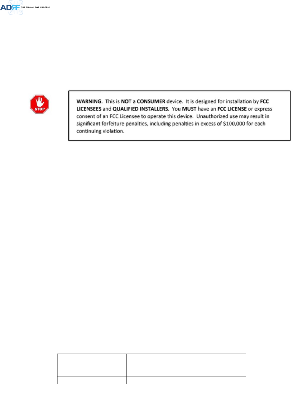
WARNING. THIS is NOT a CONSUMER device. It is designed for installation by FCC LICENSEES and
QUALIFIED INSTALLERS. You MUST have an FCC LICENSE or express consent of an FCC Licensee to
operate this device. You MUST register Class A signal boosters (as defined in 47 CFR 90.219) online
at
www.fcc.gov/signal-boosters/registration. Unauthorized use may result in significant forfeiture
penalties, including penalties in excess of $100,000 for each continuing violation.
FCC Part 90 Class A
Advanced RF Technologies, Inc.
10
Antennas must be installed in accordance with FCC 90.635. With 17 dBi gain antennas the height of
the antenna above average terrain (HAAT) must not exceed 85 m. For different gain antennas refer
to the relevant rules.
Part 90.635 requirement
This is NOT a CONSUMER device. It is designed for installation by an installer approved by
an ISED licensee. You MUST have an ISED LICENCE or the express consent of an ISED
licensee to operate this device.
WARRANTY
Any changes or modifications not expressly approved by the party responsible for compliance could
void the user's authority to operate this equipment.
FCC Part 15.21
Under Industry Canada regulations, this radio transmitter may only operate using an antenna of a type
and maximum (or lesser) gain approved for the transmitter by Industry Canada. To reduce potential
radio interference to other users, the antenna type and its gain should be so chosen that the equivalent
isotropically radiated power (e.i.r.p.) is not more than that necessary for successful communication.
Conformément à la réglementation
d’Industrie Canada, le présent émetteur radio peut
fonctionneravec une antenne d’un type et d’un gain maximal (ou inférieur) approuvé pour l’émetteur
par Industrie Canada.
Dans le but de réduire les risques de brouillage radioélectrique à l’intention desautres utilisateurs,
il faut choisir le type d’antenne et son gain de sorte que la puissance isotroperayonnée quivalente
(p.i.r.e.) ne dépassepas l’intensité nécessaire à l’établissement d’une communication satisfaisante.
RSS-GEN, Sec. 7.1.2– (transmitters)
Advanced RF Technologies, Inc.
11
This radio transmitter (identify the device by certification number, or model number if Category II)has
been approved by Industry Canada to operate with the antenna types listed below with the maximum
permissible gain and required antenna impedance for each antenna type indicated. Antenna types not
included in this list, having a gain greater than the maximum gain indicated for that type, are strictly
prohibited for use with this device.
Le présent émetteur radio (identifier le dispositif par son numéro de certification ou son numéro de
modèle s’il fait partie du matériel de catégorie I) a été approuvé par Industrie Canada pour fonctionner
avec les types d’antenne énumérés ci-dessous et ayant un gain admissible maximal et l’impédance
requise pour chaque type d’antenne. Les types d’antenne non inclus dans cette liste,ou dont le gain
est supérieur au gain maximal indiqué, sont strictement interdits pour l’exploitation de l’émetteur.
RSS-GEN, Sec. 7.1.2– (detachable antennas)
This equipment complies with RF radiation exposure limits set forth for an uncontrolled environment.
This equipment should be installed and operated with a minimum distance of 200 cm between the
radiator and your body. This transmitter must not be co-located or operating in conjunction with any
other antenna or transmitter. RF exposure will be addressed at time of installation and the use of
higher gain antennas require larger separation distances.
RF Radiation Exposure
L’antenne (ou les antennes) doit être installée de façon à maintenir à tout instant une distance
minimum de au moins 200 cm entre la source de radiation (l’antenne) et toute personne physique.
Cet appareil ne doit pas être installé ou utilisé en conjonction avec une autre antenne ou émetteur.
RSS-102 RF Exposure
Advanced RF Technologies, Inc.
12
2. TOPOLOGY
Figure 2-1 FiRe-78-4 DAS topology
3. CABLE CONNECTION
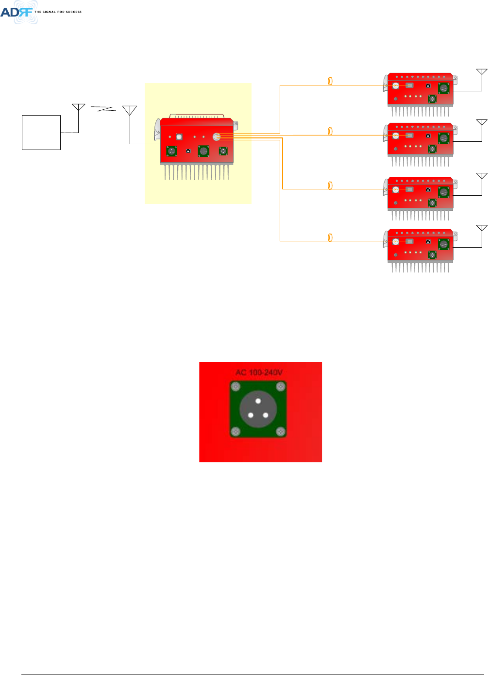
3.1 AC Power
Figure 3-1 AC Power port
AC power is accepted through a standard 3-wire male plug (MS3106A-22-2S) with phase, neutral and ground leads.
The AC power is wired to a high efficiency DC switching power supply which is UL listed. The power supply runs the
amplifiers and device including RF Module, controller, LED, etc.
The metal enclosure of this equipment is connected to ground.
OPTIC GUI
BATTERY
ADRF-BBU ONLY
AC IN
100-240V
EF-UL IN EF-UL OUT EF-DL OUT EF-DL IN
SERVER
OPTIC GUI
BATTERY
ADRF-BBU ONLY
AC IN
100-240V
EF-UL IN EF-UL OUT EF-DL OUT EF-DL IN
SERVER
OPTIC GUI
BATTERY
ADRF-BBU ONLY
AC IN
100-240V
EF-UL IN EF-UL OUT EF-DL OUT EF-DL IN
SERVER
OPTIC GUI
BATTERY
ADRF-BBU ONLY
AC IN
100-240V
EF-UL IN EF-UL OUT EF-DL OUT EF-DL IN
SERVER
OPTIC
ADXV-R-3378P-N4X
OPTIC
EXT_ULEXT_DL
GUI Ext. ALARM BATTERY
ADRF-BBU ONLY
AC 100-240V
DONOR
DONOR_CPL
(-30dB)
ADXV-R-3378P-N4X
ADXV-R-3378P-N4X
ADXV-R-3378P-N4X
FiRe-78-4
Base
Station
OPTIC
OPTIC
OPTIC
Advanced RF Technologies, Inc.
13
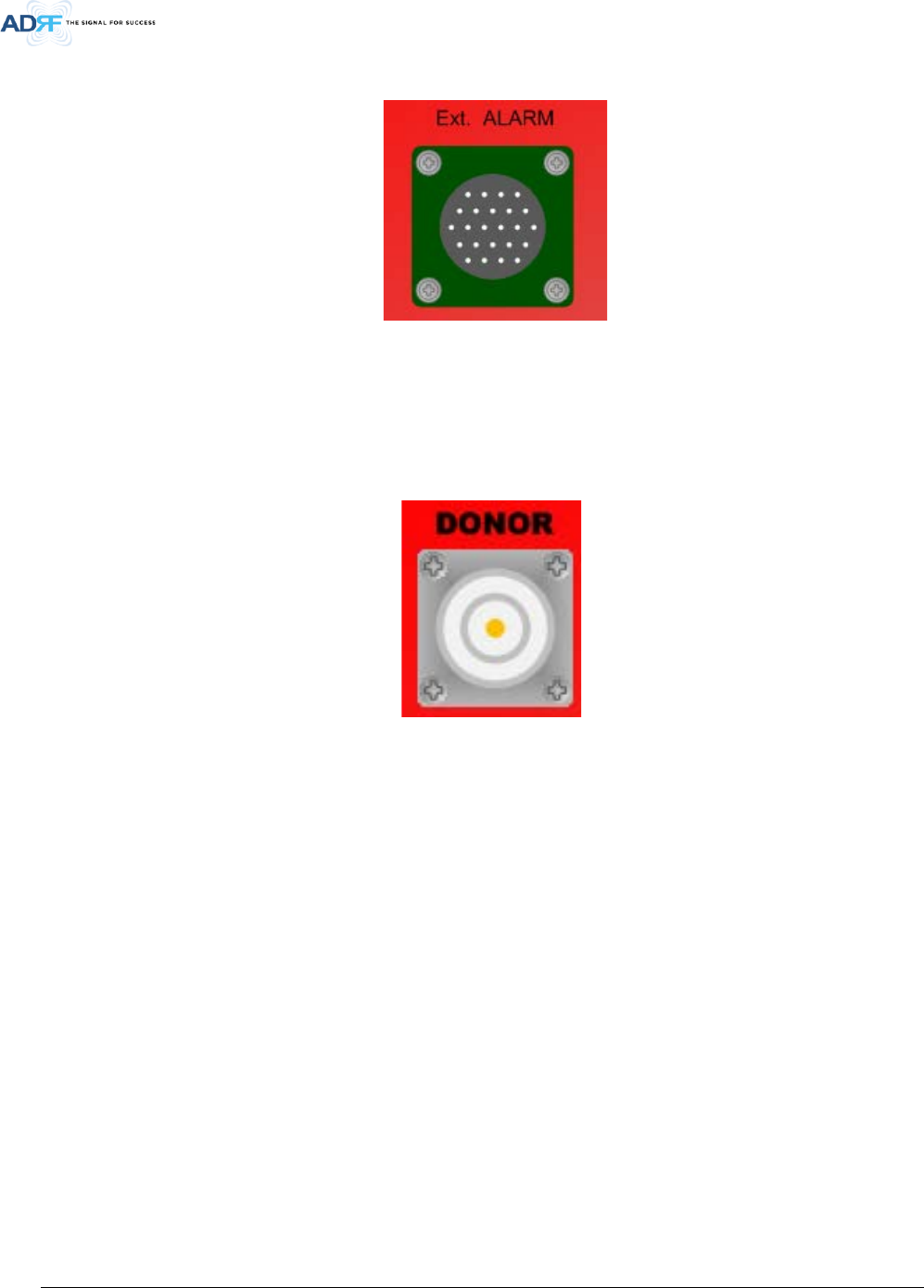
3.2 External Alarm
Figure 3-2 External Alarm port
This port should be connected only to ADRF External Alarm Box.
3.3 RF
Figure 3-3 RF port
The RF connections are made via three “4.3-10” female connectors. The RF connector labeled “DONOR” must be
connected to each antenna pointing towards the base station.
The RF connections must be made through cables with characteristic impedance of 50 ohms.
Advanced RF Technologies, Inc.
14
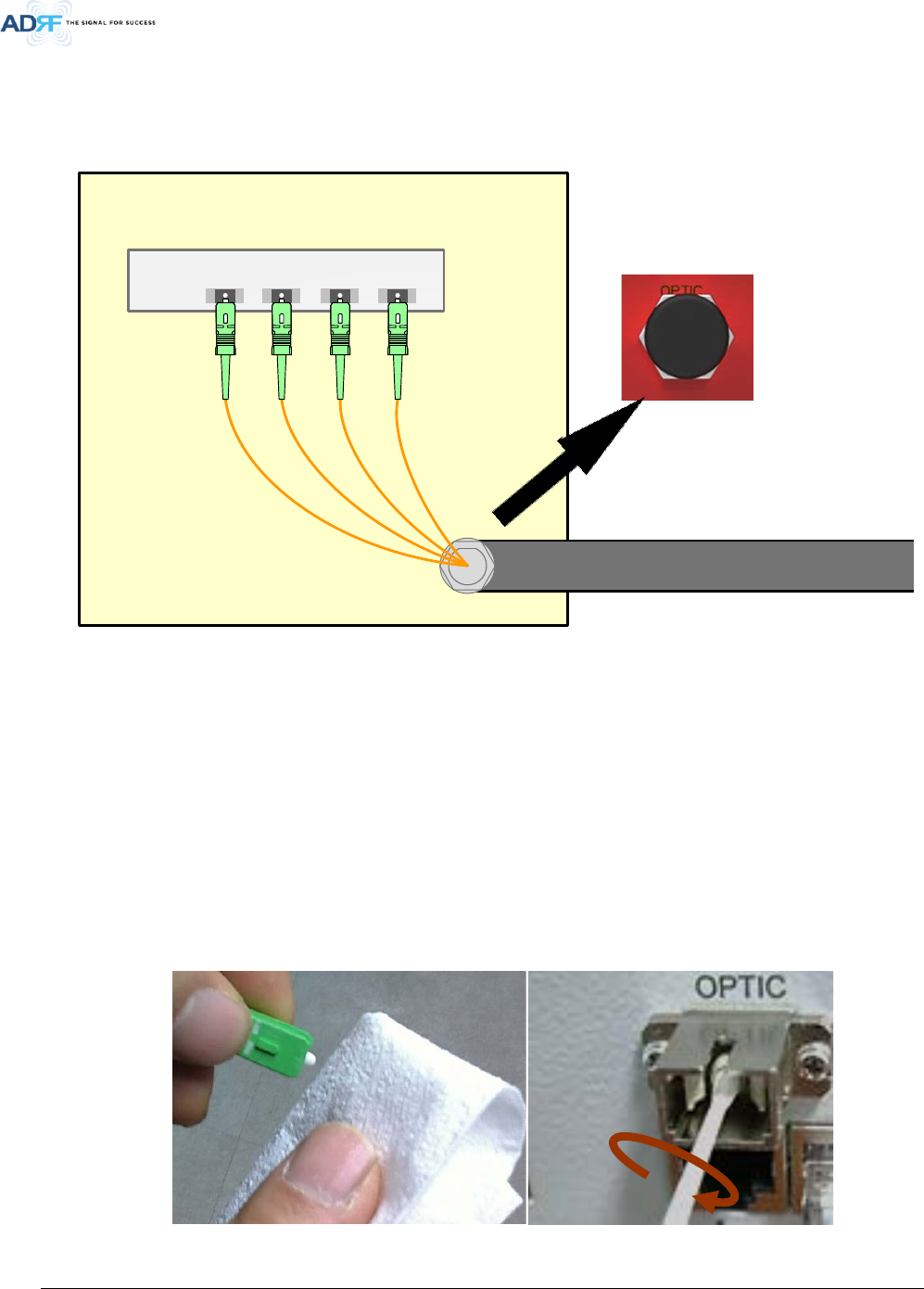
3.4 Optic
Figure 3-4 Optic port
ODU located inside of equipment has 4 optic ports (SC/APC type) for link to ADXV-R-3378P-N4Xs.
You must verify to keep optic contact be clean and optic line’s curvature be not allowed in order to be free from
optic loss when you install optic line and conduit.
• We recommend cleaning optic connector using a dry optical cleaning swab or tissue in a dry environment
as needed. We recommend cleaning the optic connectors only if the expected optic loss is higher than
the loss reported in the Web-GUI by 1.5dBo. (Figure 3-5)
• When optic connector are not in use, the port should be covered with a protective dust cap. (Figure 3-6)
•
•
Figure 3-5 Optic Connector Cleaning (left) and Optic Port Cleaning (right)
Conduit for optic
ODU LINK1LINK2LINK3LINK4
OPTIC
Inside of Fire-78-4 (Conduit connector)
SC/APC
Adpator

Advanced RF Technologies, Inc.
15
•
•
Figure 3-6 SC/APC Optic Connector Dust Cap
3.5 Battery
This port should be connected to ADRF 24VDC BBU (Battery back-up unit) via dedicated cable provided by ADRF.
3.6 Grounding
A ground cable is included in the box. The grounding terminals are located at lower right-hand side of the
equipment. The grounding cable should be properly connected before powering on the equipment.

Advanced RF Technologies, Inc.
16
Figure 3-7 Protective Earthing Conductor
Ground terminals located on the side consisted of a 16mm²(6AWG) and should be permanently connected to
earth(Protective earthing conductor).
4. RF EXPOSURE WARNING
In order to comply with the FCC RF exposure requirements, the antenna installation must comply with the following:
The outdoor antenna (Yagi type or similar directional antenna if off air donor signal used) must be installed so as to
provide a minimum separation distance of 0.3 meters (60 cm) between the antenna and persons within the area.
(This assumes a typical antenna with gain of [10.1 dBi, VSWR ≤ 1.5:1, Zo= 50 ohms, and a cable attenuation between
1-10 dB).
The indoor antenna (Omni directional or leaky cable) must be installed so as to provide a minimum separation
distance of at least 8 inches (20 cm) between the indoor antenna connected to the RF booster and the human user’s
Advanced RF Technologies, Inc.
17
body within the area. (This assumes a typical wide beam type antenna with gain of 0-2 dBi, VSWR ≤ 2:1, Zo= 50
ohms, and a cable attenuation of between 1-10 dB).
5. INSTALLATION
DO NOT APPLY A.C. POWER TO THE BDA UNTIL CABLES ARE CONNECTED TO BOTH PORTS OF
THE BDA AND THE ANTENNAS.
1. To mount on a wall. Using appropriate screws and anchors, attach the BDA to the wall at the four mounting
holes
2. Ensure that the isolation between the donor antenna and the service antenna is at least 15 dB greater than
the BDA gain.
3. Connect the cable from the donor antenna to the BDA connector labeled “DONOR” and the cable from the
service antennas to the BDA connector labeled “SERVER”.
4. Connect the AC power cord to the BDA and turn on the switch at the left-hand of PSU.
5. Installation of the equipment is now complete. Adjust the gain controls to suit the specific signal
environment through GUI on your PC.
- To prevent feedback, the donor and server antennas must be separated by an appropriate distance to
provide sufficient isolation. Isolation is attained by separating antennas a sufficient distance so that the
output of one antenna does not reach the input of the other. This distance is dependent on the gain of the
repeater.
- Prior to equipment use the service must be registered with the FCC. This can be done through the FCC’s
website at https://signalboosters.fcc.gov/signal-boosters)
6. DEFAULT ITEMS
Items
Model name
Antenna
Cable
Coupling device
7. SPECIFICATIONS
Advanced RF Technologies, Inc.
18
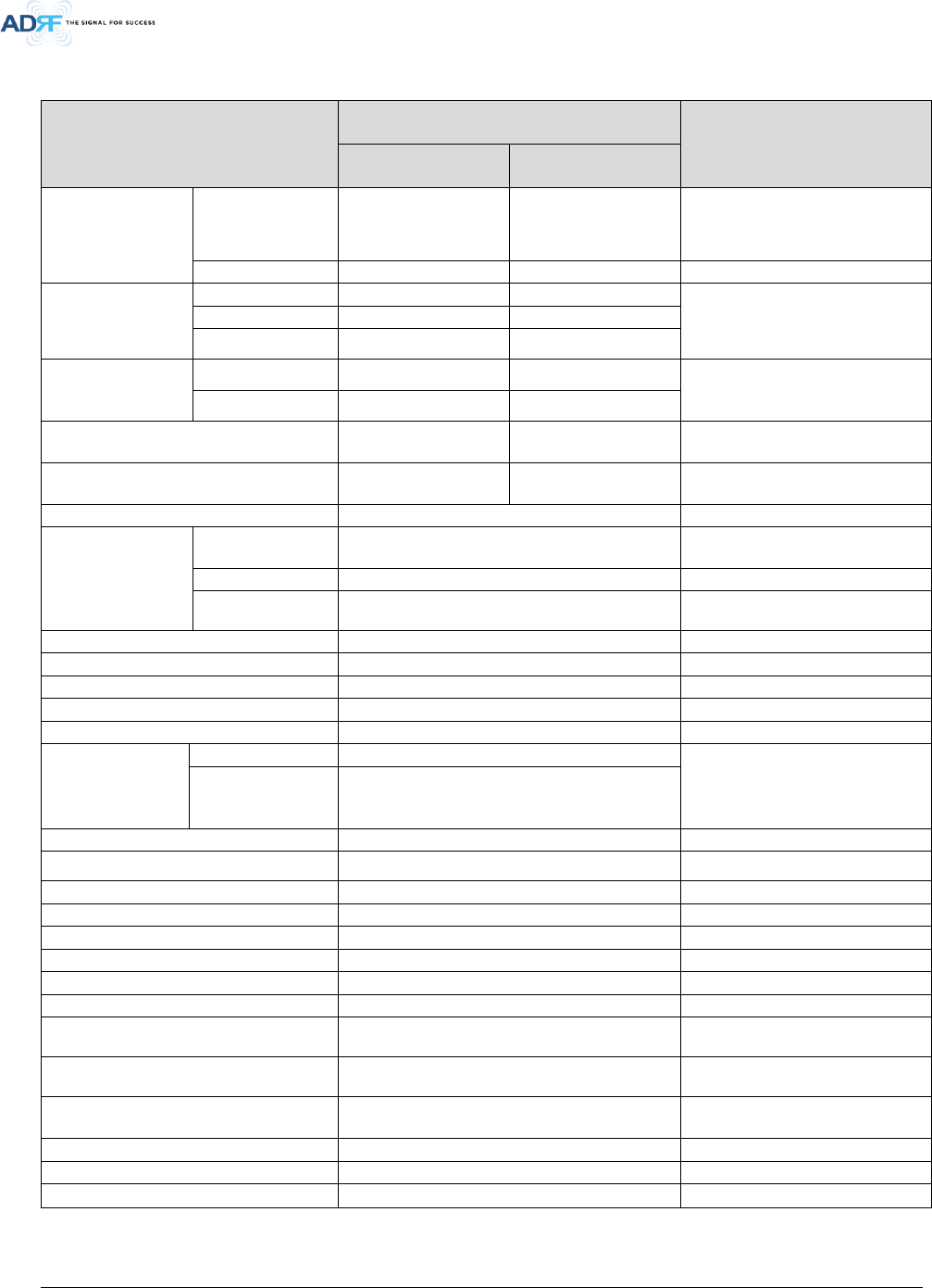
7.1 Electrical Specifications
Parameters
Specifications
Remarks
DL UL
Frequency Range
(MHz)
PS 700
769 - 775MHz(For FCC)
(768-769MHz Guard
band)
768 - 775 MHz (For ISED)
799 - 805 MHz(For FCC)
(798-
799MHz Guard
band)
798- 805 MHz (For ISED)
PS 800
851 - 861
806 - 816
Composite Output
Power of FiRe-78-4
PS 700
-24dBm
30dBm
PS 800
-24dBm
30dBm
PS 700 + PS 800 -24dBm 30dBm
Composite Output
Power of FiRe-78-
4+ADXV-R-78PS
PS 700 33dBm 30dBm
PS 800 33dBm 30dBm
System total Gain (dB)
[FiRe-78-4+ ADXV-R-3378P-N4X]
95 85
System total Input power
[FiRe-78-4+ADXV-R-3378P-N4X]
-62dBm -55dBm
Filter selection
Narrow
Simultaneous Filter
Support numbers
Narrow Band
Up to 16(Non-contiguous) @ PS 700 / PS 800
Up to 32(Non-contiguous) @ PS 700 + PS 800
Narrow(kHz)
6.25, 12.5, 25
Narrow(kHz) ≥ 60dBc@Filter Bandwidth Edge + 3 x Filter BW
Spurious
FCC Rule Compliant
Passband Ripple
±2 dB
ALC Dynamic Range
≥ 60dB
DL Path Only
Gain Dynamic Range
≥ 40dB
Channel Setting Resolution
0.025 kHz
System
Group Delay
Broad Band
<6.5us
Except of optic cable delay,
Except of ADXV-R-3378P-N4X
Narrow Band
≤85us@6.25KHz_BW
≤46us@12.5KHz_BW
≤28us@25KHz _BW
Power Supply
100 -240 VAC, 60Hz (Free Voltage)
With battery backup,
Power Consumption <135Watt
Max RF Input Power without over drive
-20dBm
UL Noise Figure @ Max. Gain
5.0dB Center Frequency
[ADXV-R-3378P-N4X+ FiRe-78-4]
No damage Max Input Power
+10dBm
DL Path Only
Enclosure Cooling
Natural Convection
Impedance
50 Ω
VSWR
<1.5 : 1
DL/UL Input
ODU number per NEMA4-x 1 ODUs(; max 4 RUs)
Dry Contacts NFPA 72 2016 Code Compliant
Remote Alarming /
Network Management
Dry Contacts, Web-GUI, SNMP, SNMP-Traps
(External Wireless Modem Required)
Relative Humidity
5% - 90%
Operating Temperature
-40°F to +140°F (-40°C to +60°C)
NFPA 1221 2016 Code Compliancy
Compliant

Advanced RF Technologies, Inc.
19
7.2 Mechanical Specifications
Dimensions W x D x H
11.03 x 21.28 x 10.01 inches
without mount bracket
Weight
60.5lbs (without mount bracket)
64.0lbs (with mount bracket)
RF Connector 4.3-10(Female)
Expansion port for V/UHF 2 SMA(Female) port
Weather Resistances IP66
Optic terminal tray(; inside) 1
4 optic cables per optic tray in the
enclosure
Advanced RF Technologies, Inc.
20
8. FiRe-78-4 Web-GUI Setup
The Web-GUI allows the user to communicate with the repeater either locally or remotely. To connect to the
repeater locally, you will need a laptop with an Ethernet port and an RJ-45 crossover cable. To connect to the
repeater remotely, you will need to have an active internet connection via an external modem or LAN.
8.1 Repeater/PC Connection Using Web-GUI
Verify that your Local Area Network Connection is set to obtain an IP address automatically under the Internet
Protocol (TCP/IP) properties.
If you are connecting to the unit remotely (use of a modem), then skip step above.
Connect the RJ-45 crossover cable between the laptop’s Ethernet port and the repeater’s Ethernet port.
Launch an Internet Browser.
Type the following IP address into the address bar of the Internet Browser: http://192.168.63.1
If you are connecting to the unit remotely, then type the IP address of the modem to connect to the unit
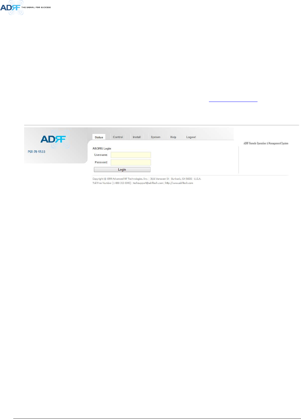
The following login screen will appear:
• Figure 5-1 Login Page
If you are not the Administrator, please type in your assigned username & password which you should have
received from the Administrator.
The default username and password for the General User is adrf & adrf, respectively.
The default Administrator login is admin & admin, respectively.
Advanced RF Technologies, Inc.
21
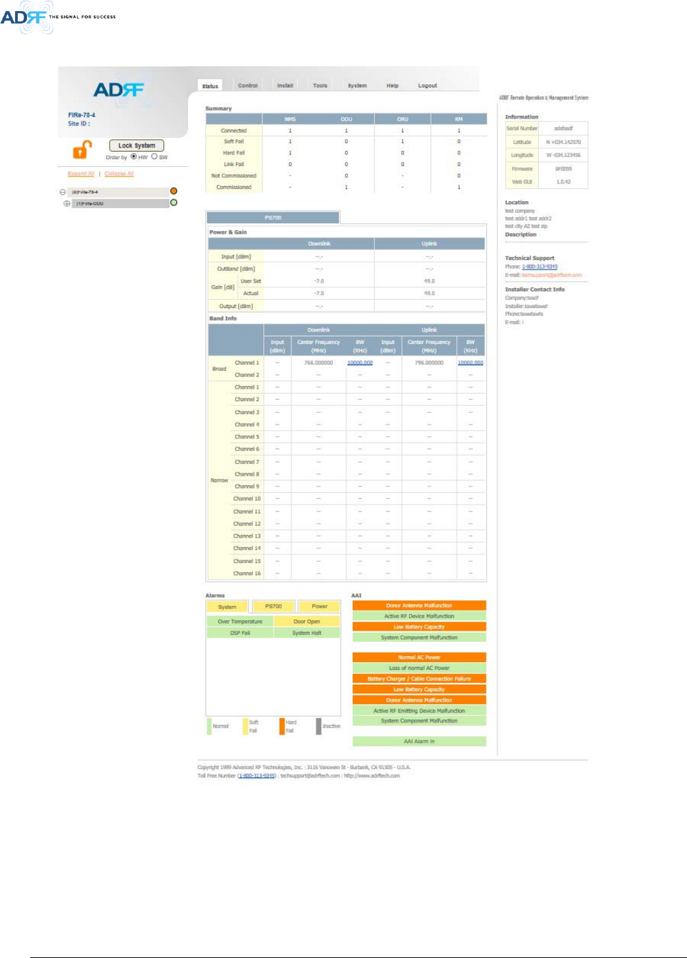
8.2 Status Tab
• Figure 5-2 Status Tab
Advanced RF Technologies, Inc.
22
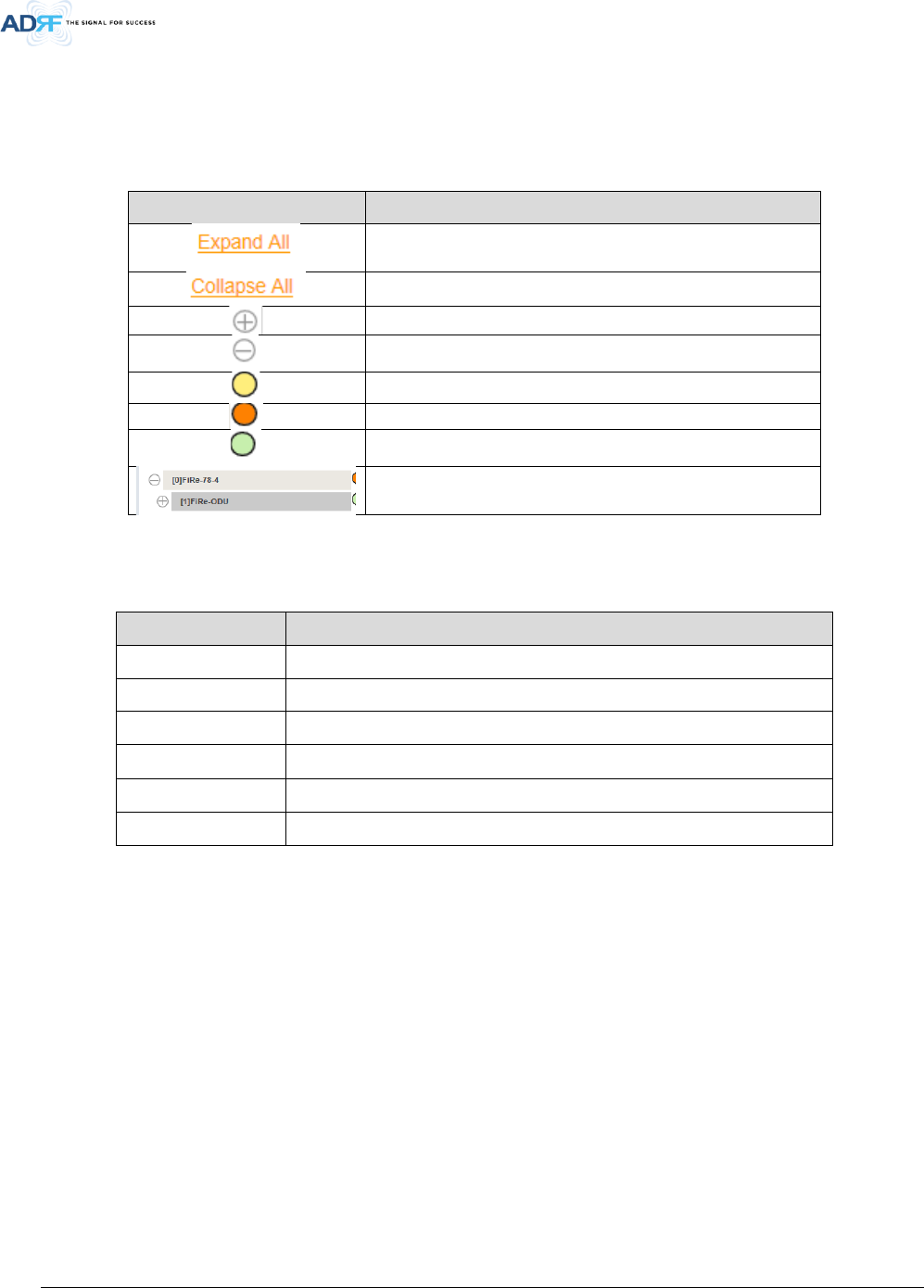
8.2.1 Navigation Tree
The navigation tree located on the left hand side of the Web-GUI allows the user to switch between the
various modules that are connected to the system.
Table 7-1 Navigation tree
Parameters Description
Expands the entire navigation tree
Collapses the entire navigation tree
The module has the expandable subordinate modules
The branch is currently expanded
The module has soft fail alarm
The module has hard fail alarm
The module has no alarms (normal)
The selected module will have bright gray color
8.2.2 System Summary
Table 7-2 System Summary Description
Parameters Description
Connected Display the number of modules physically connected to ADXV DAS
Soft Fail Display the number of soft fail present on each module
Hard Fail Display the number of hard fail present on each module
Link Fail Display the number of link fail present on each module
Not Commissioned Display the number of non-commissioned or commission failed module
Commissioned Display the number of successfully commissioned module
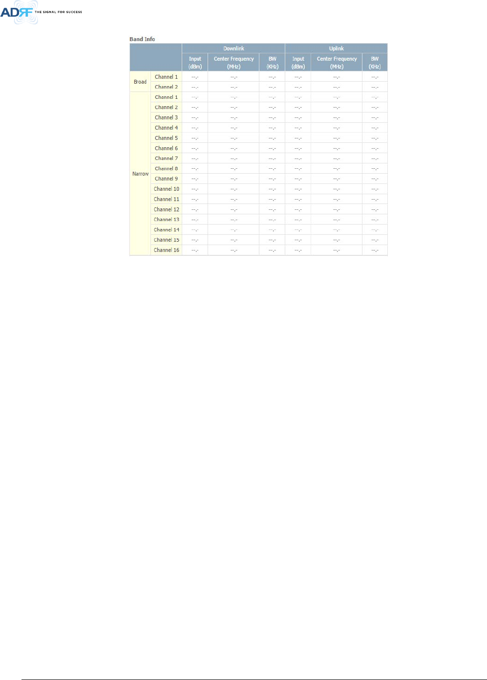
8.2.3 Band Info
The Band Info section displays frequency information along with the corresponding bandwidths that have been
set from the Install tab. Input levels for each channel are also displayed in this section.
Advanced RF Technologies, Inc.
23
• Figure 5-3 Band Info Display
8.2.4 Power & Gain
This section displays the Input, Gain, and Output for both downlink and uplink.
• Figure 5-4 Power & Gain Display
Input [dBm] – Displays the in-band Downlink/Uplink signal level. The system will display “--.-“ when the input
level is < -90 dBm.
Outband [dBm] – Displays the out-band composite power.
Gain [dB]
User Set: Displays the amount of gain that the user set.
Actual: Displays the actual amount of gain that is currently in use.
Output [dB] – Displays the Downlink/Uplink composite output power levels. The system will display “--.-“, when
the output level is < +5 dBm.
Advanced RF Technologies, Inc.
24
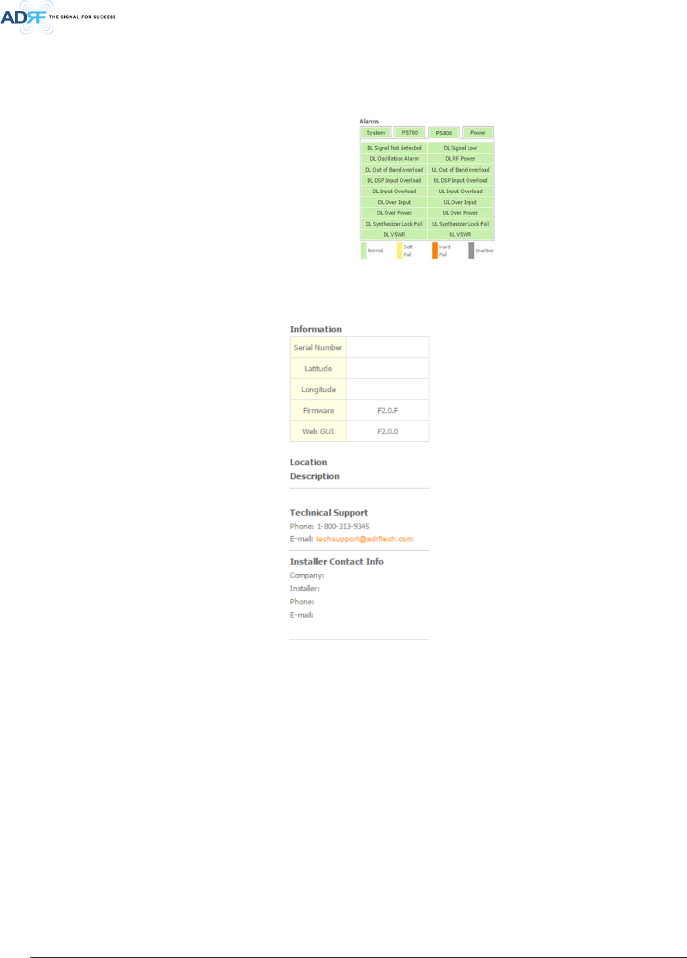
8.2.5 Alarms
This section displays the alarm status for System alarms, RF Alarms, and Power alarms. If an alarm is present in
the system, then the color of the alarm tab will change according to the type of failure.
• Figure 5-5 Alarm Display
8.2.6 Repeater Info / Repeater Location / Technical Support / Installer Contact Info
• Figure 5-6 Repeater Info / Repeater Location / Technical Support / Installer Contact Info
Repeater Info: Displays the serial number, latitude, longitude, firmware version, and Web-GUI version
Repeater Location: Displays the address where the repeater is installed
Technical Support: Displays ADRF’s Technical Support contact information
Installer Contact Info: Displays the installer’s name, phone, and e-mail address
Note: Once successfully logged in, the repeater model name and the site/cascade ID will be displayed on the
top of all the windows (except for the Main Window).
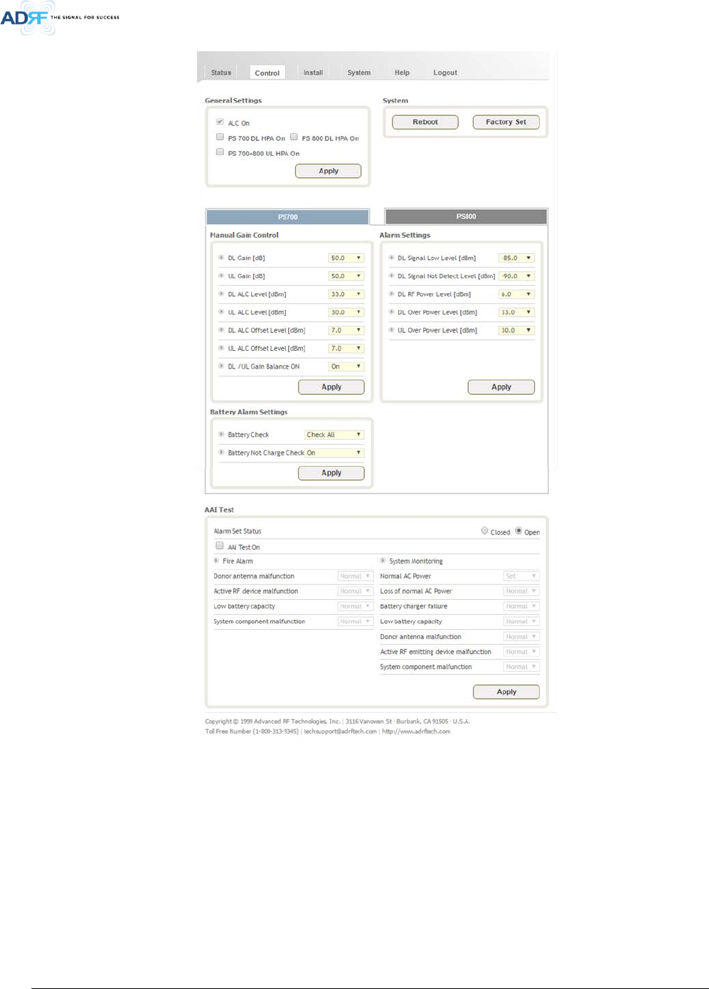
8.3 Control Tab
Advanced RF Technologies, Inc.
25
• Figure 5-7 Control page
Advanced RF Technologies, Inc.
26
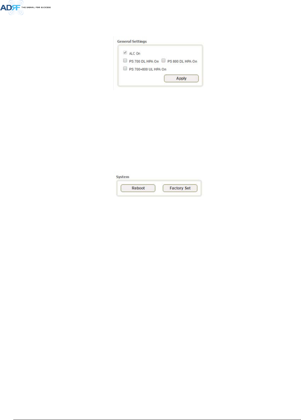
8.3.1 General Setting
The General Setting section allows the user to enable/disable amplifiers and the ALC routine.
• Figure 5-8 General Setting
ALC ON: Enables or disables Automatic Level Control (ALC)
PSR 700 DL HPA On: Enables or disables the Downlink High Power Amplifier (HPA) for 700MHz PS
PSR 800 DL HPA On: Enables or disables the Downlink High Power Amplifier (HPA) for 800MHz PS
PSR 700+800 UL HPA On: Enables or disables the Uplink High Power Amplifier (HPA) for 700+800MHz PS
To enable/disable any of the settings, click on the checkbox and click the Apply button.
8.3.2 System
Under the System section, the user is able to perform soft reboot on the repeater and also can restore factory
default settings.
• Figure 5-9 System
Reboot: Performs a soft reboot of the repeater
Factory Set: Restores all settings to factory defaults
8.3.3 Manual Gain Control
• Figure 5-10 Manual Gain Control Setting
DL/UL Gain: Gain levels of the repeater can be specified here
DL/UL ALC Level: Prevents the output power from exceeding the specified value
DL/UL Output ALC Offset: If any ALC attenuation has been applied, the system will release this attenuation
when the signal level drops by the specified level
DL /UL Gain Balance ON: Allows the user to enable or disable the gain balance. When gain balance is enabled,
the delta value between the downlink and uplink gains remain constant

Advanced RF Technologies, Inc.
27
8.3.4 Alarm Settings
• Figure 5-11 Alarm Settings
DL Signal Low Level: Allows the user to specify how low the signal can be before triggering a “Downlink Signal
Low” soft-fail alarm
DL Signal Not Detected Level: Allows the user to specify how low the signal can be before triggering a “Downlink
Signal Not Detected” soft-fail alarm
DL RF Power Level: Allows the user to set a maximum deviation value for the downlink RF power before
triggering a “DL RF Power Level” soft-fail alarm
For example, if the input signal is -50 dBm and the gain is set to 60 dB, the expected output power should be 10
dBm. If the Downlink RF Power alarm value is set to 6dB, then a soft-fail alarm will trigger if the output power falls
below 4 dBm
DL Over Power Level: DL Over Power Alarm will trigger when the DL output level exceeds this level
UL Over Power Level: UL Over Power Alarm will trigger when the UL output level exceeds this level
Battery Check:
• Check All – All battery related alarms are checked which include Battery Fail, Battery Not Installed, Low
Battery, and Battery Not Charge
• Except Install – Only Battery Fail, Low Battery, and Battery Not Charge alarms are checked
• Check Off – Does not perform any battery check
Battery Not Charge Check:
• On – Checks for the Battery Not Charge alarm
• Off – Disables the check for the Battery Not Charge alarm
Advanced RF Technologies, Inc.
28
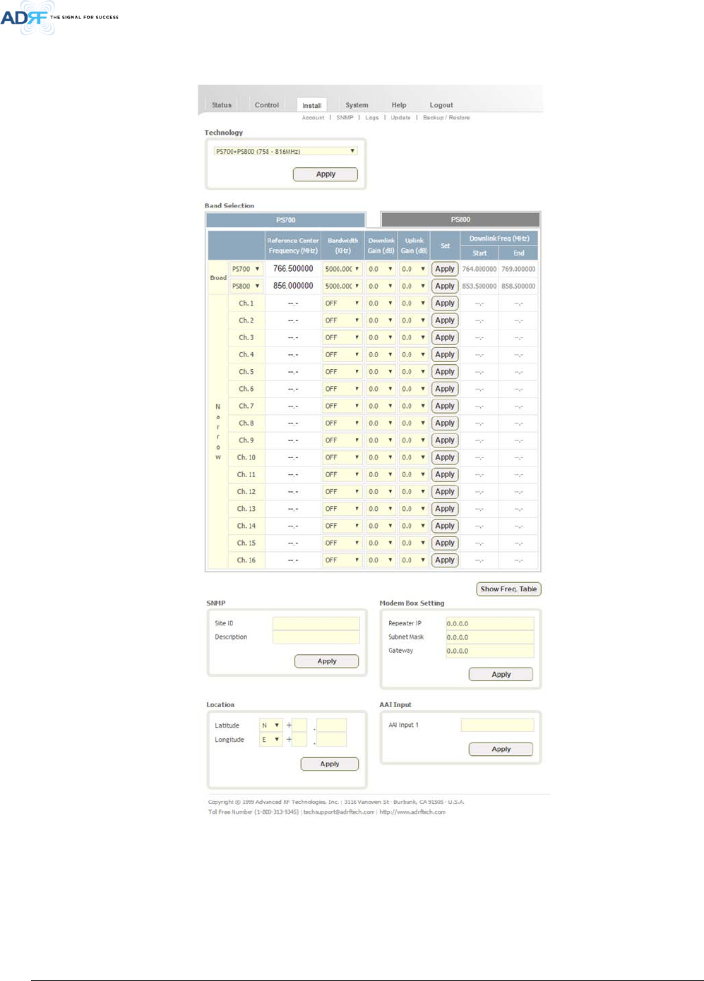
8.4 Install Tab
8.4.1 Install
• Figure 5-12 Install Page
Advanced RF Technologies, Inc.
29
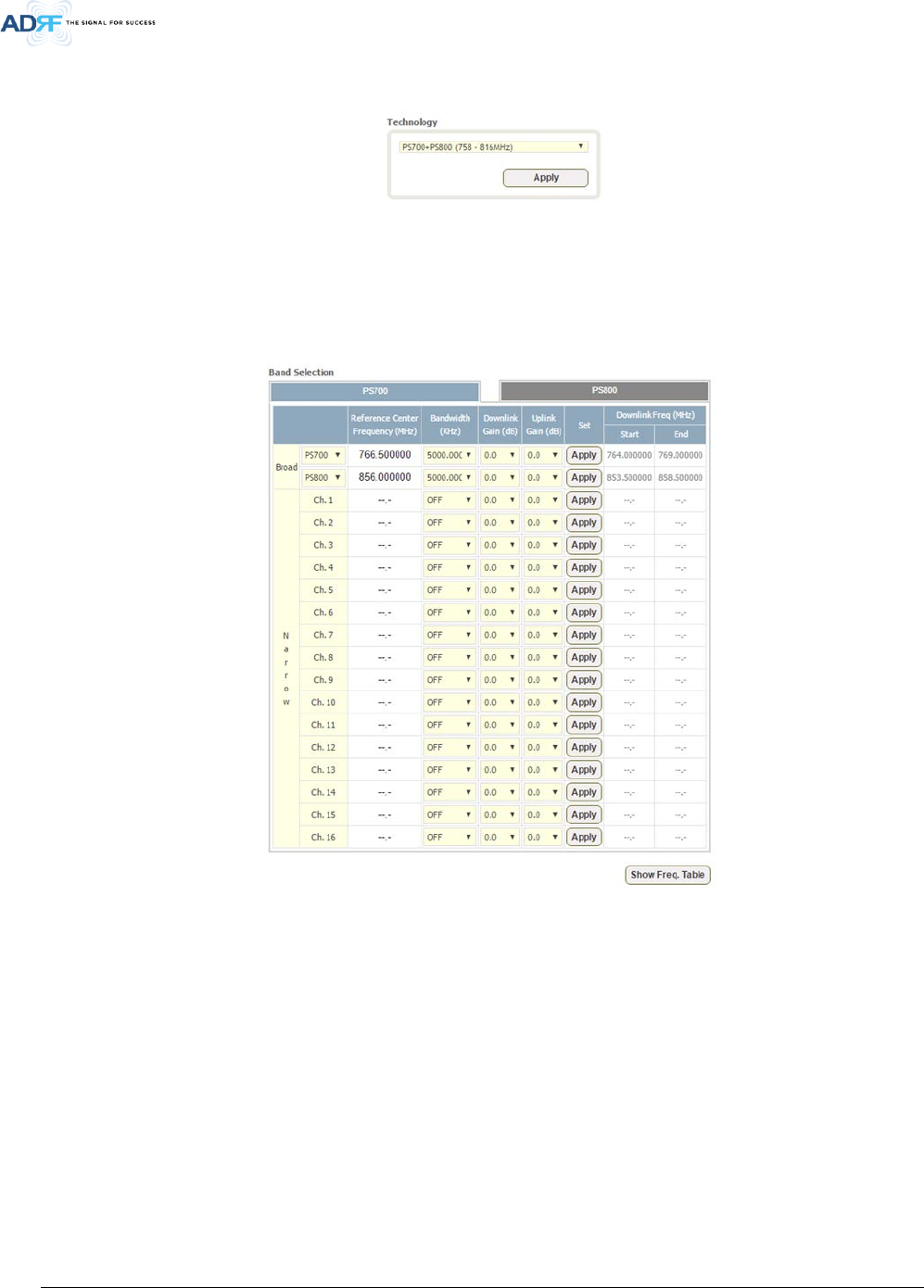
8.4.2 Technology
This section allows the user to set the repeater mode to either use PS700, PS800, or PS700+PS800.
• Figure 5-13 Technology
The following choices are available from the dropdown:
• PS700 (769-775MHz)
• PS800 (851-861MHz)
• PS700+PS800 (769-861MHz)
8.4.3 Band Selection
• Figure 5-14 Band Selection
Band selection allows the user specify the desired frequncies by inputting the center frequencies and selecting
the bandwidths.
Reference Center Frequency: The user can input the center frequency of the pass-band.
Bandwidth: Allows the user to select the desired bandwidth for the passband. Choices for wide band
frequencies include 5 and 10MHz. Narrow band choices include 6.25, 12.5, 25.0, and 200 KHz.
Downlink/Uplink Gain: Minor gain adjustments can be performed on a per channel basis to equalize signal
levels
Downlink Freq - Start: Displays the start frequency of the pass-band once the band selection has been set
Downlink Freq - End: Displays the end frequency of the pass-band once the band selection has been set
8.4.4 SNMP
Advanced RF Technologies, Inc.
30
• Figure 5-15 SNMP
The SNMP section allows you to specify the Site ID and Description. The Site-ID is the code that is used to
identify the repeater.
8.4.5 Location
This section allows the user to input the latitude and the longitude of the repeater.
• Figure 5-16 Location Setting
8.4.6 Modem Box Setting
This section allows the user to specify alternative Repeater IP, Subnet Mask, and Gateway settings. These
settings are enabled when the Host/Remote switch is set to the Remote position.
• Figure 5-17 Modem Box Setting
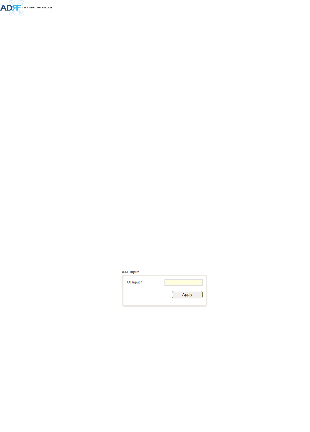
8.4.7 AAI Input
The PSR-VU-9537 can accept a dry contact input alarms. The alarm can be labeled in this section. Once the
alarm is labeled, it will show up in the system with the new custom names on the Status tab.
• Figure 5-18 AAI Input
Advanced RF Technologies, Inc.
31
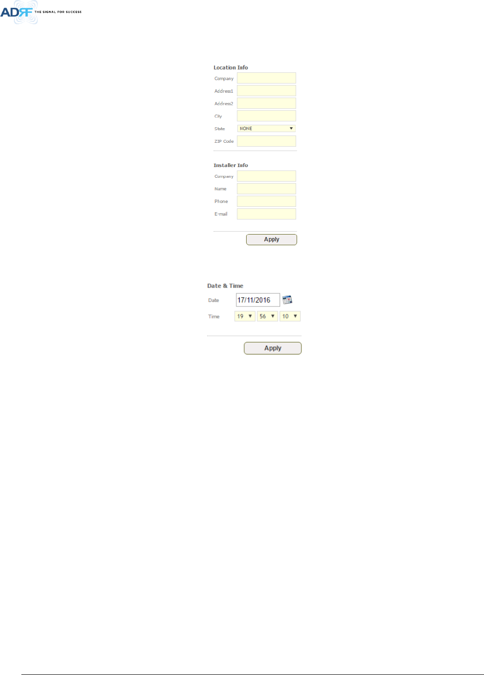
8.4.8 Location Info / Installer Info
This section allows the user to specify the address of the repeater and also the information of the installer.
• Figure 5-19 Repeater Location Info / Repeater Installer Info
8.4.9 Date & Time
This section allows the user to specify the current date and time.
• Figure 5-20 Date & Time Setting

Advanced RF Technologies, Inc.
32
8.5 System
The System tab allows the user to perform firmware updates, upload closeout packages, view any changes to
the system, backup existing configuration, and add/remove user accounts, and change the login credentials of the
Administrator.
8.5.1 System: Account
8.5.1.1 System: Account – Account Management
The Account Management section allows the Administrator to delete any user accounts. Please note that the
Account Management section is only available if you are logged into the system as the Administrator. To delete a
user account click on the Account Management link and under the Delete column, click on the delete button.
• Figure 5-21 System: Account- Account Management
8.5.1.2 System: Account – New Account
The New account section allows the Administrator to create a new user account. Please note that the New
account section is only available if you are logged into the system as the Administrator. To create a new user account
click on the new account link and fill in the fields shown.
Figure 5-22 System: Account- New Account
8.5.1.3 System: Account – Change Password
The Change Password section allows the current user who is logged into the system to change their login
credentials.
• Figure 5-23 System: Account- Change Password
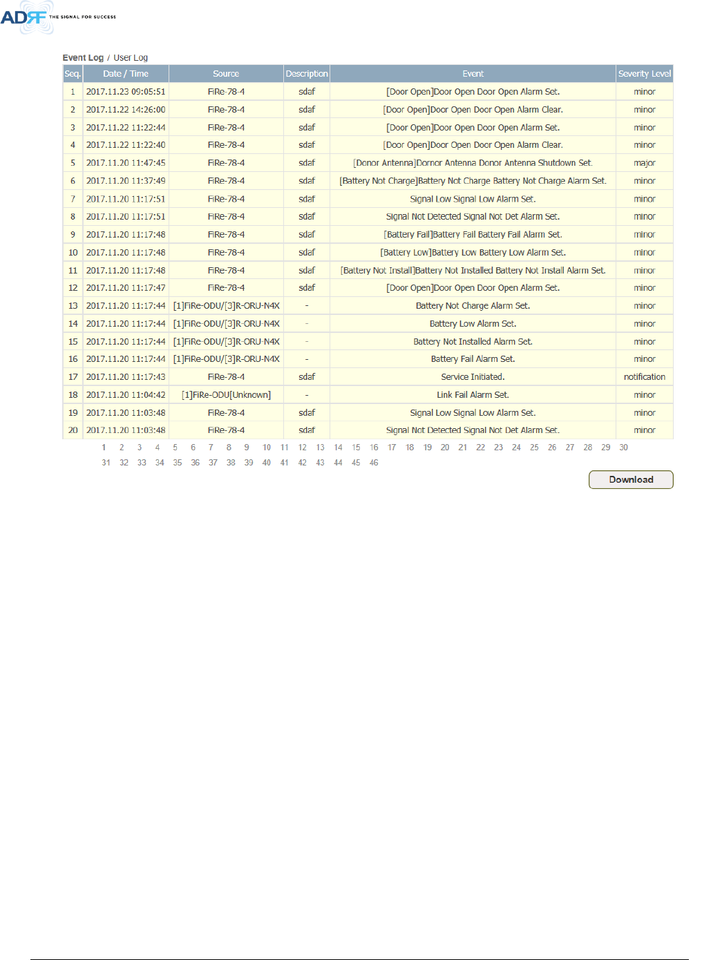
8.5.2 System – User Log
This section displays system events that have taken place. The User Log displays who has made the changes,
the time and date of when the event took place, and what changes were made to the system.
Advanced RF Technologies, Inc.
33
• Figure 5-24 System – User Log
Advanced RF Technologies, Inc.
34
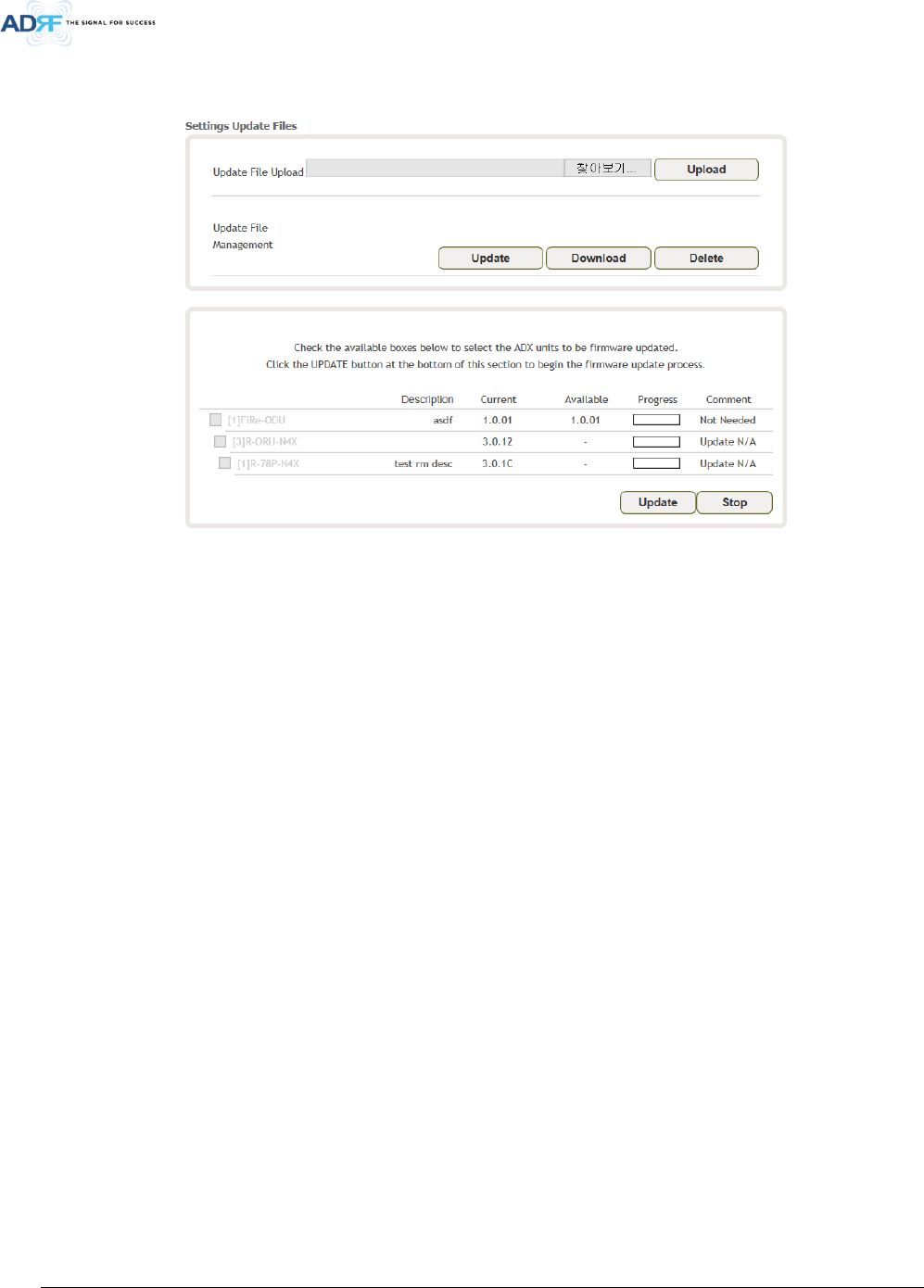
8.5.3 System – Update
To perform a firmware update, click on the Update tab and the following screen will appear.
• Figure 5-25 System – Update
Click on the Choose File button and locate the firmware file.
Click on the Upgrade button to perform the firmware update.
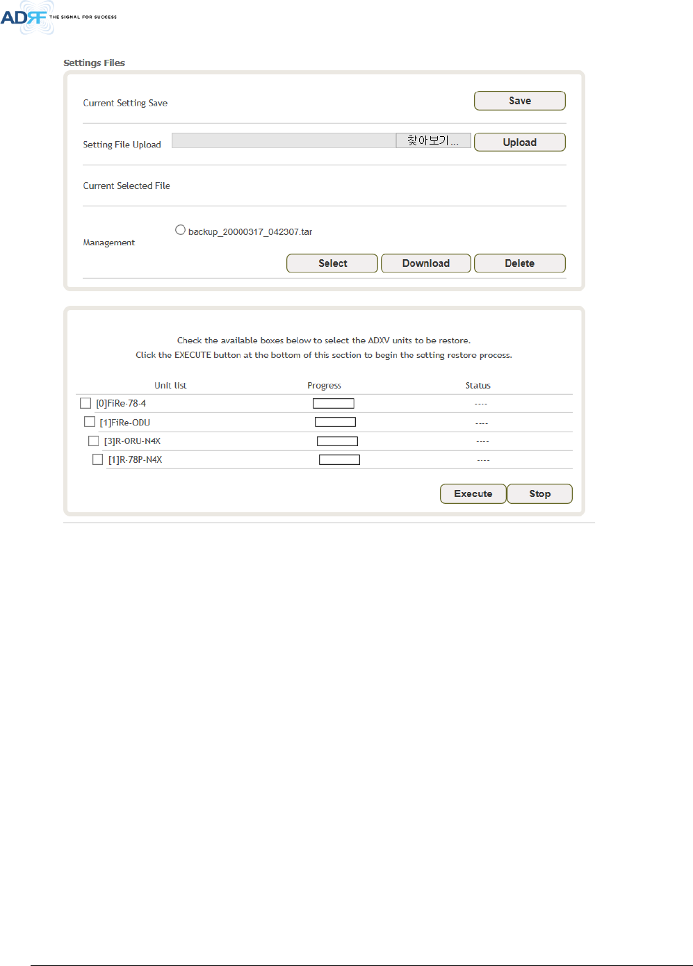
8.5.4 System – Backup & Restore
The backup section allows the user to save the settings. To perform the backup, click on the Backup button and
system save the backup file. To restore the settings to the system, click on Choose File button, select the backup
file, restore unit and click the excute button.
Advanced RF Technologies, Inc.
35
• Figure 5-26 System Backup

Advanced RF Technologies, Inc.
36
8.6 Help
If an internet connection is available, clicking on the Help Tab will redirect the user to our Technical Support
page.
• Figure 5-27 Help
8.7 Logout
Clicking the Logout button will log the current user off the system.