ADTRAN TRC6410L2X TRACER 6410 User Manual TRACER 6000 Series Integrated System Manual
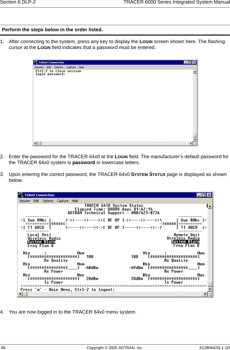
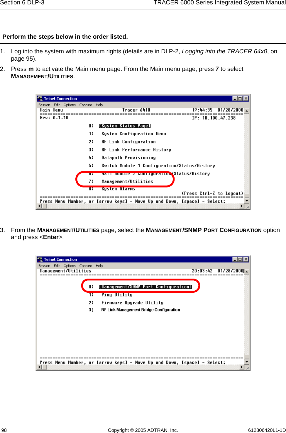
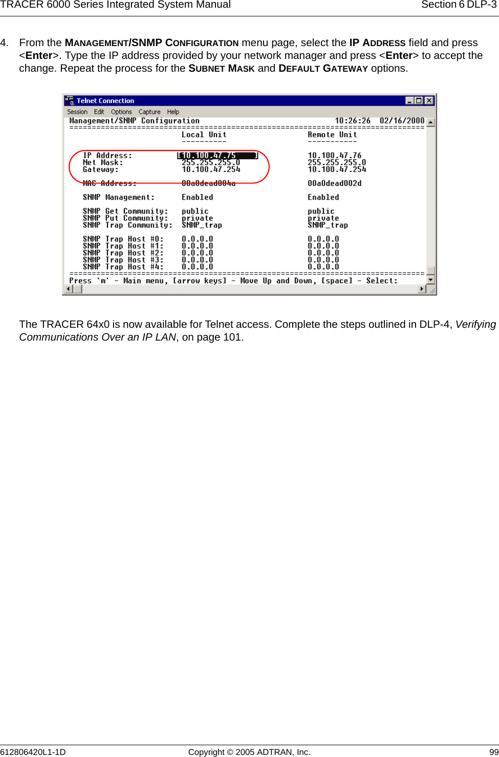
Adtran TRACER 6410 TRACER 6000 Series Integrated System Manual
UserManual.wiki
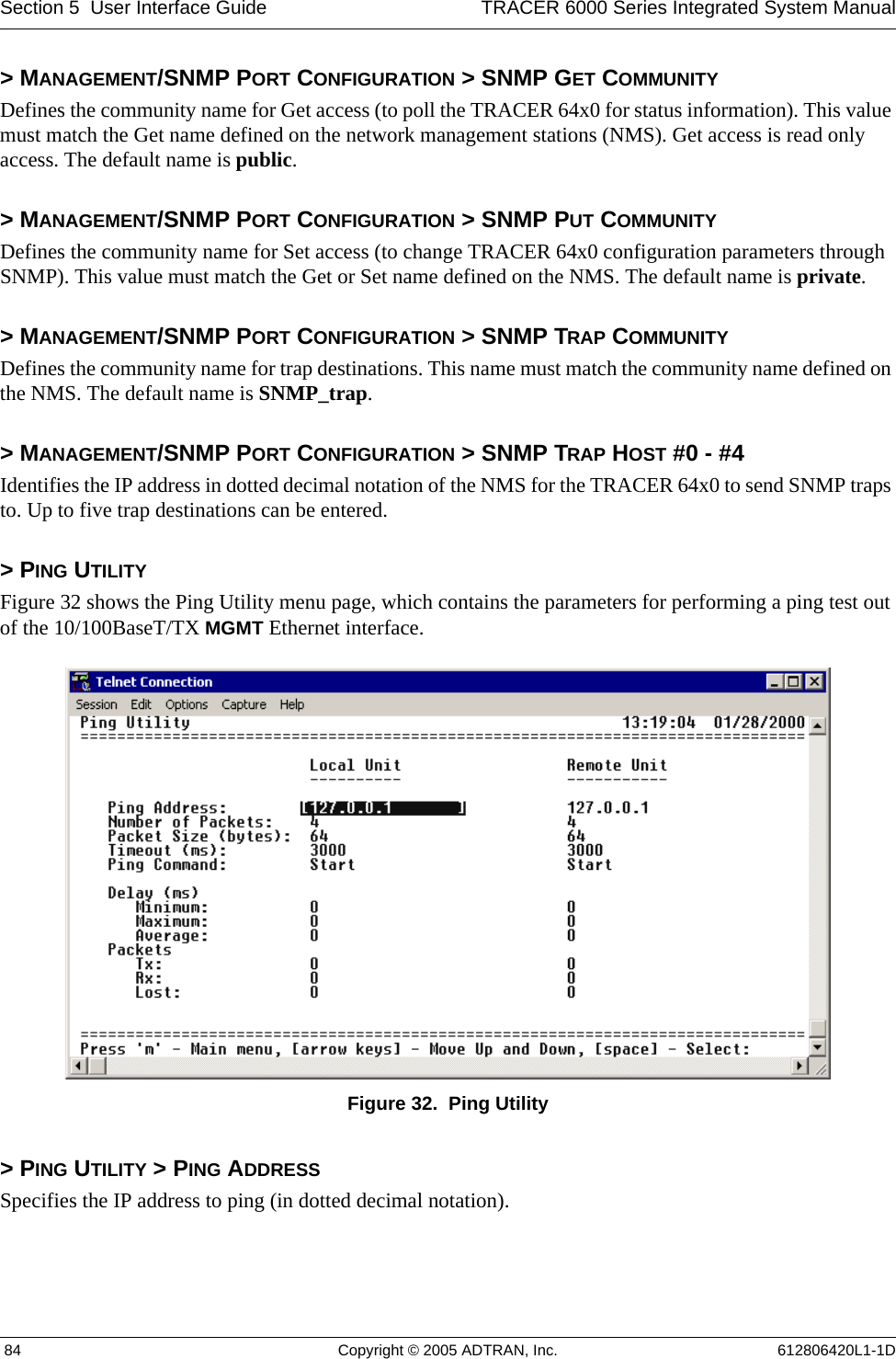
>
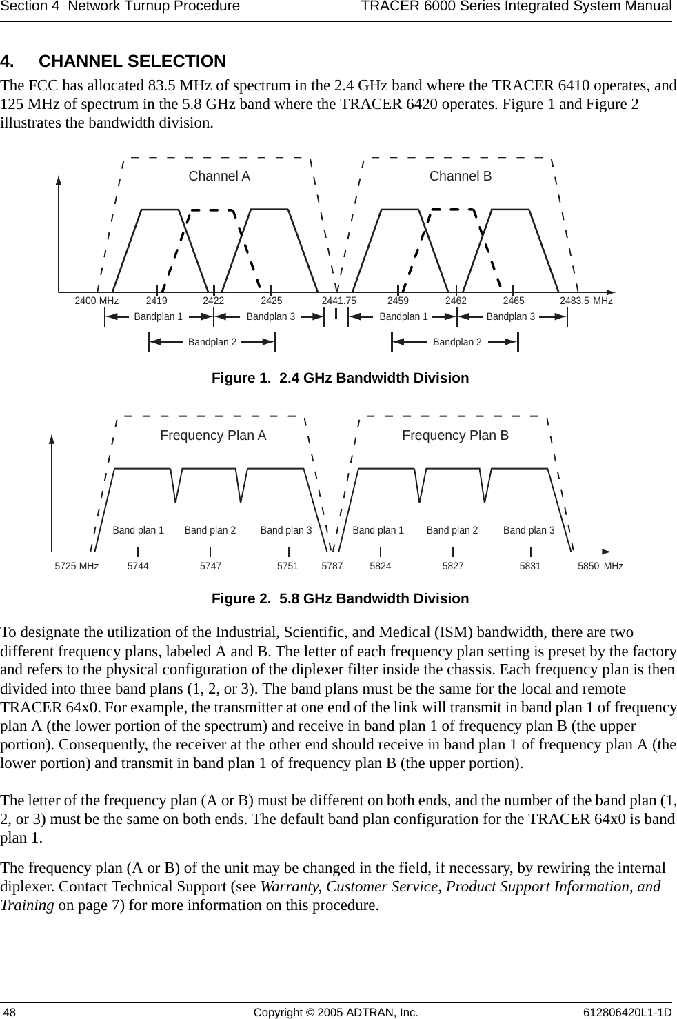
ADTRAN
>
TRC6410L2X User Manual
Users Manual
Navigation menu
Upload a User Manual
Namespaces
Wiki Guide
HTML
PDF
Info
Views
User Manual
Discussion / Help
Navigation
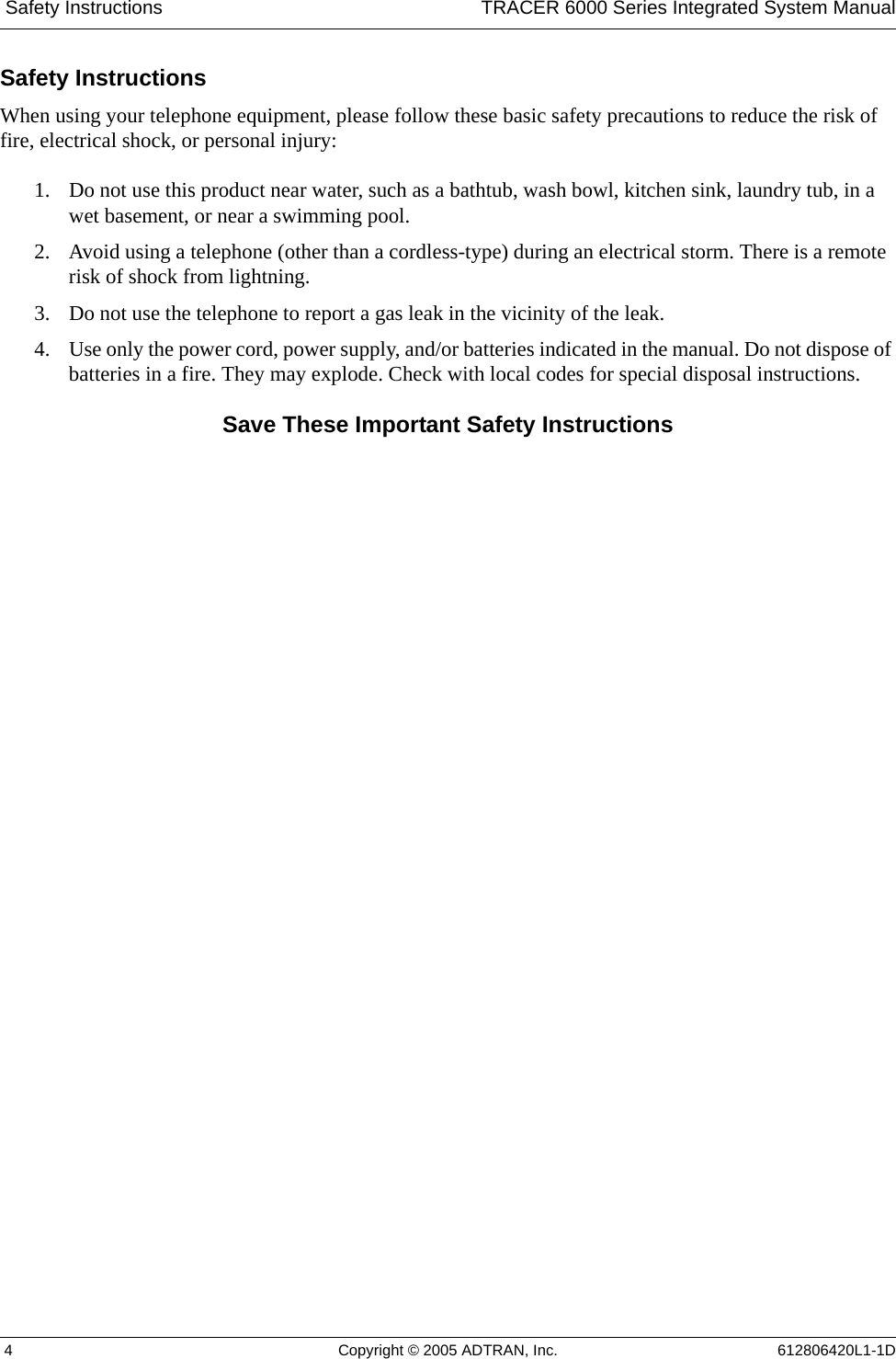
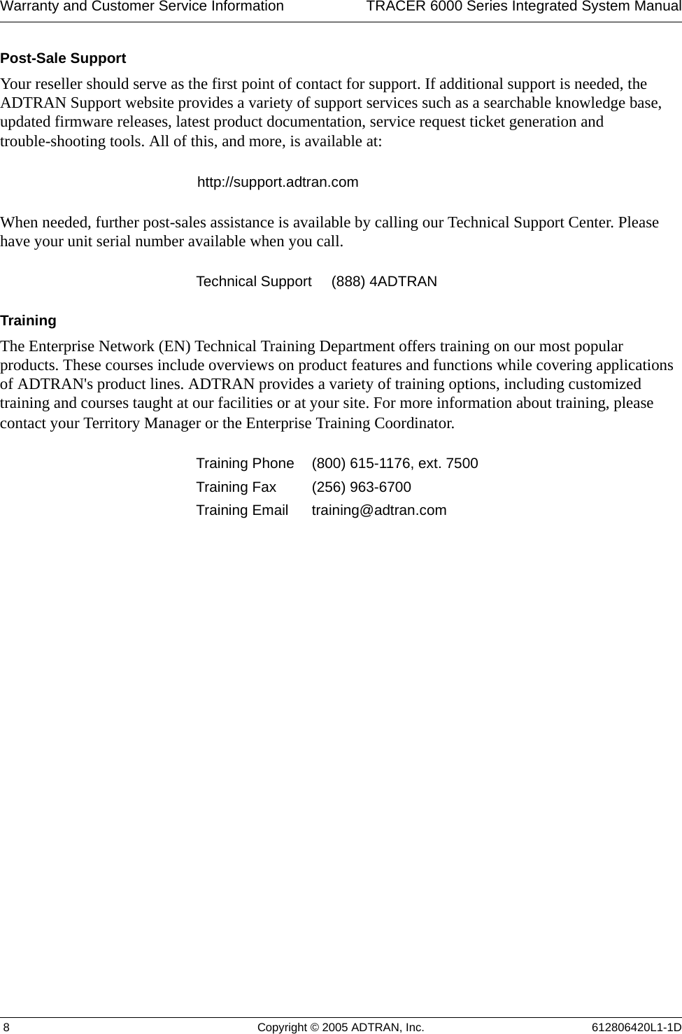

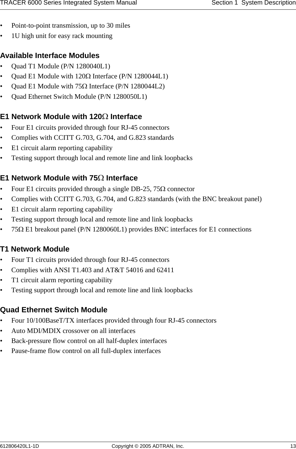
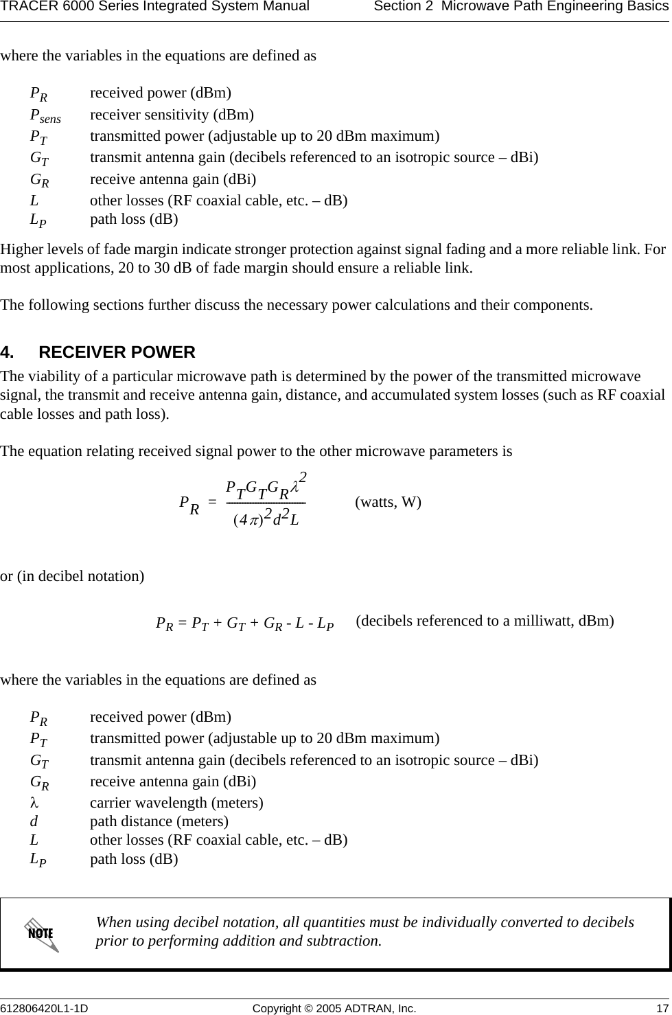
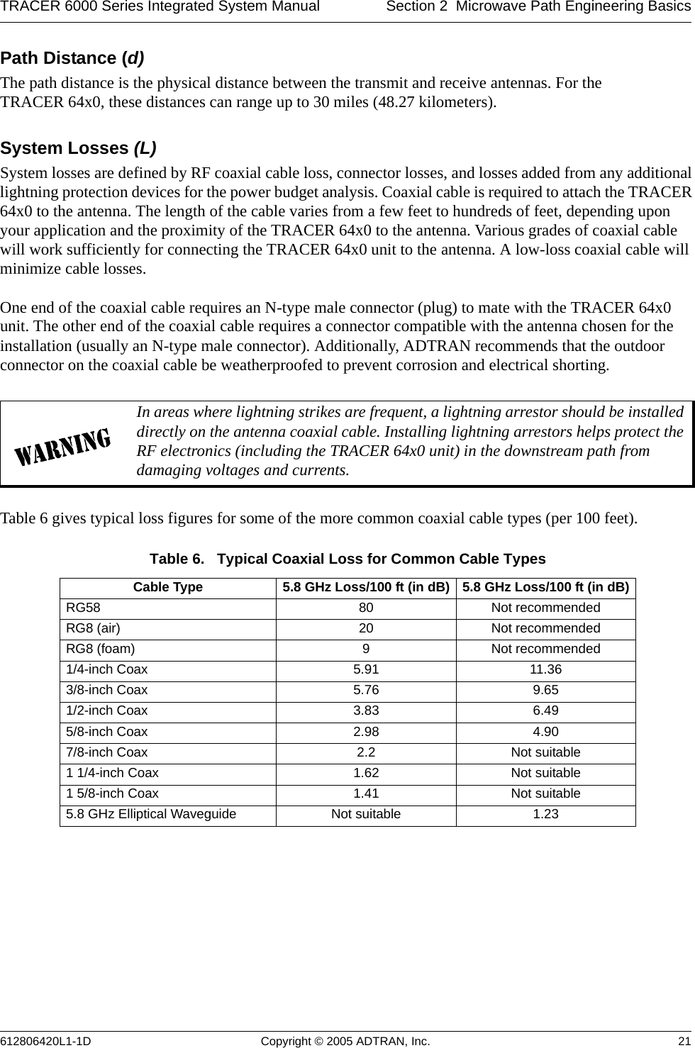
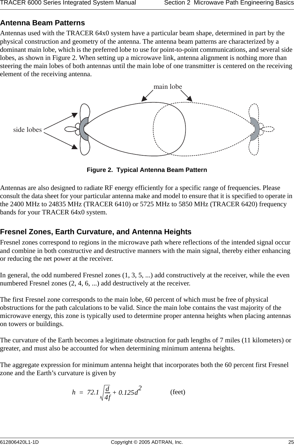
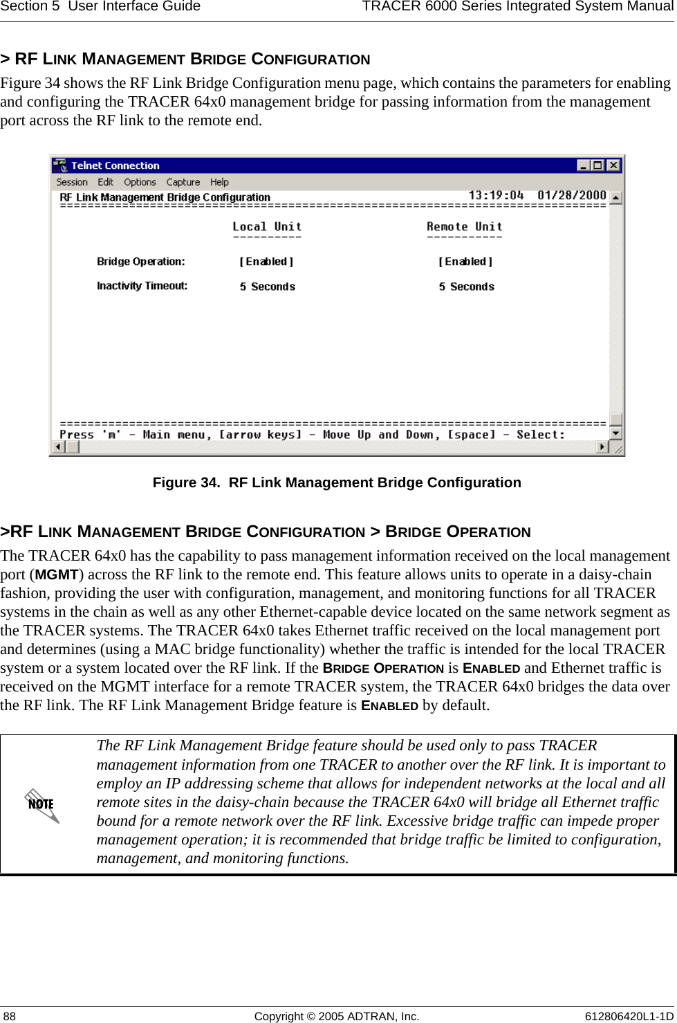
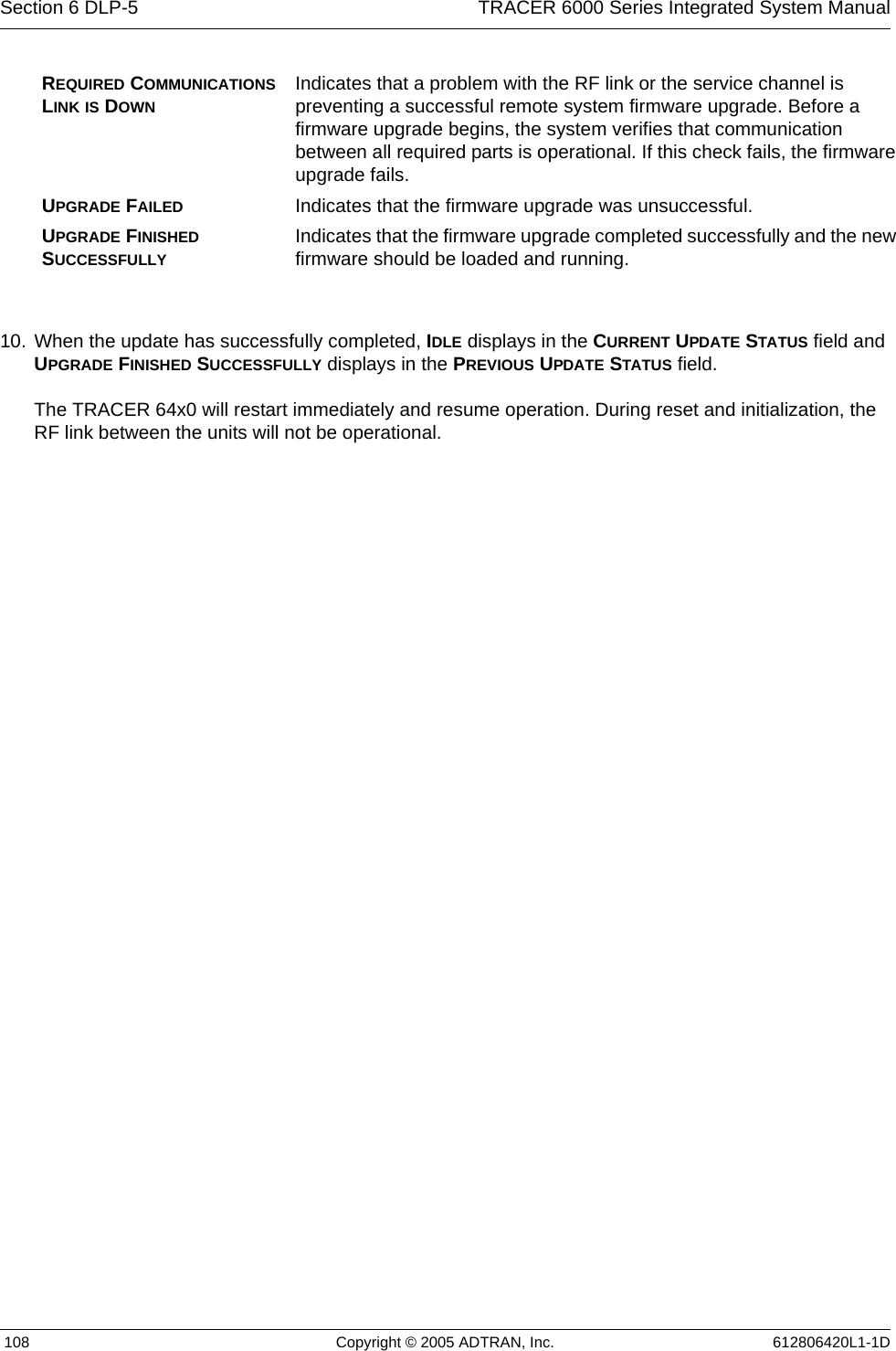
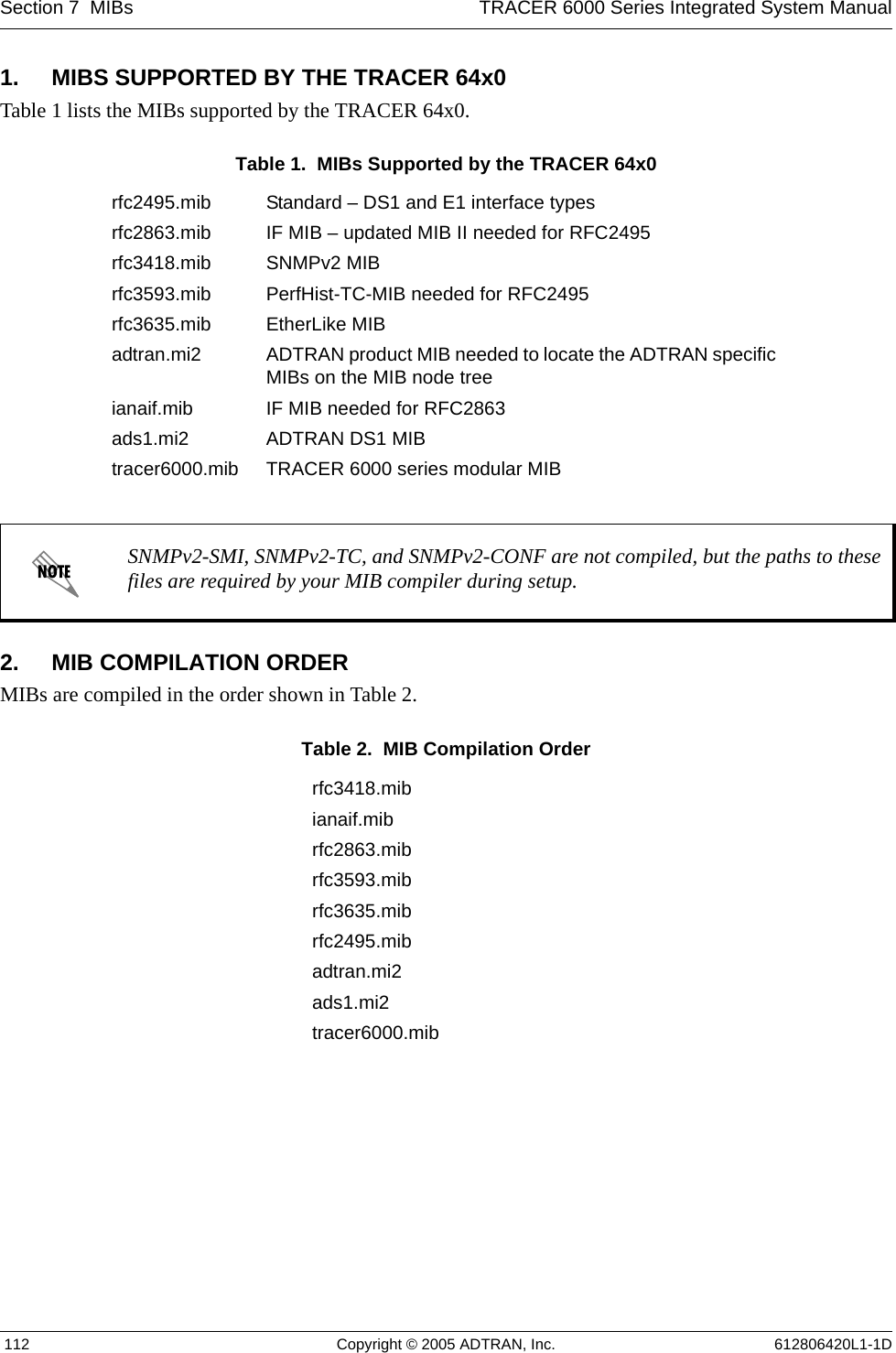
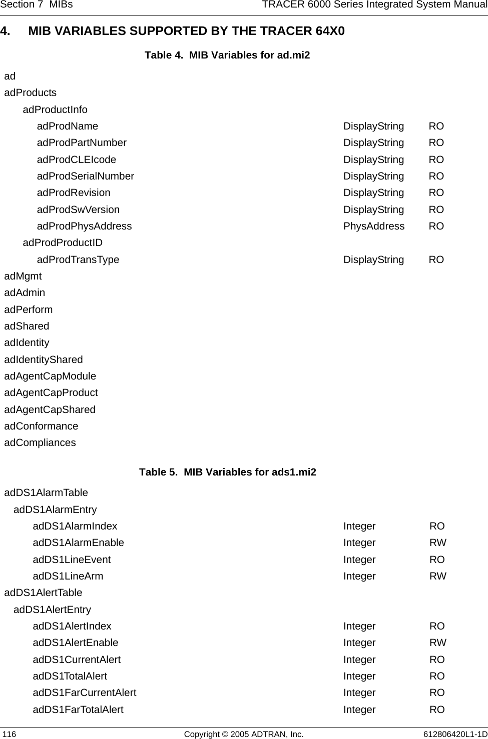
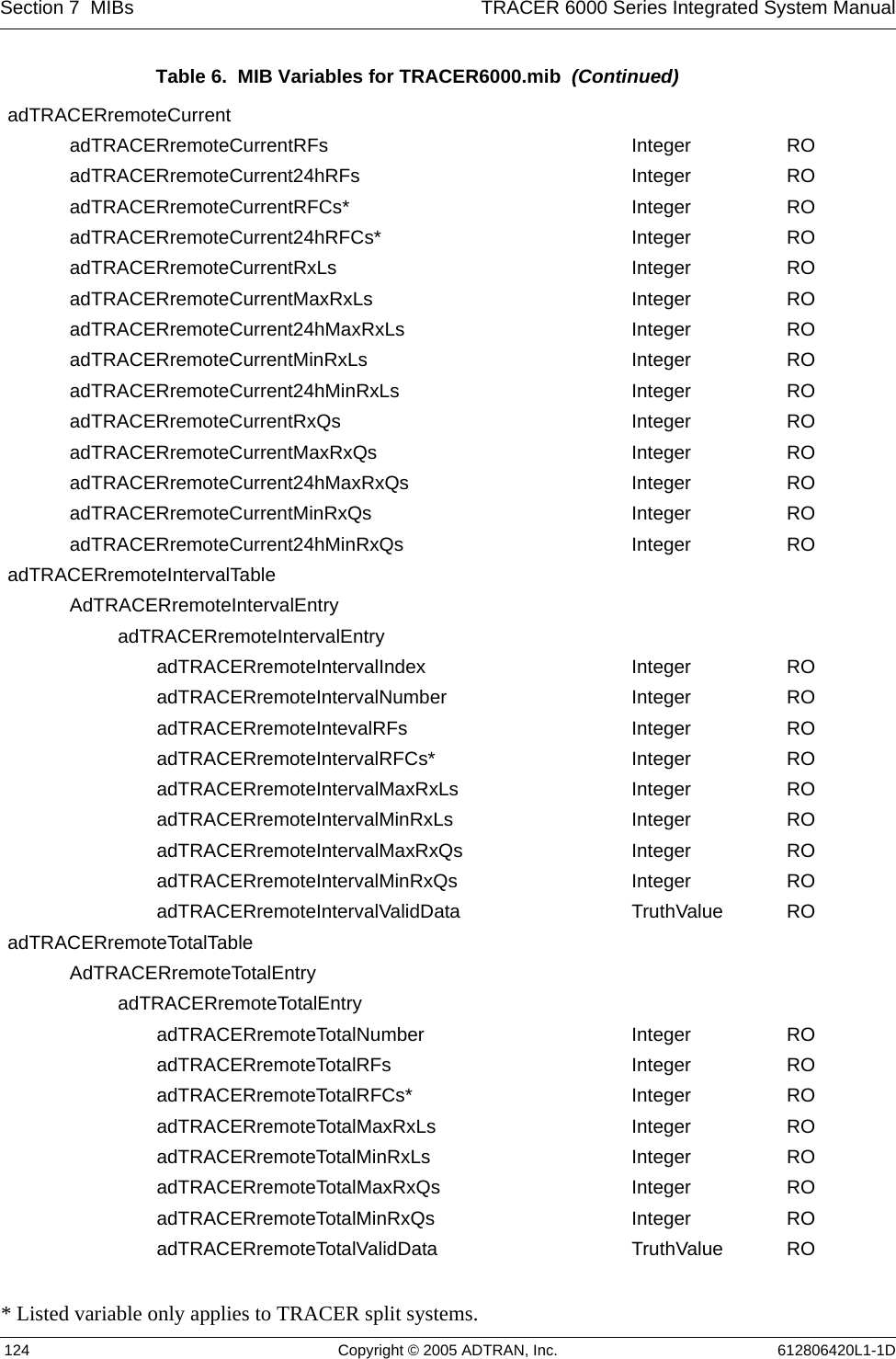
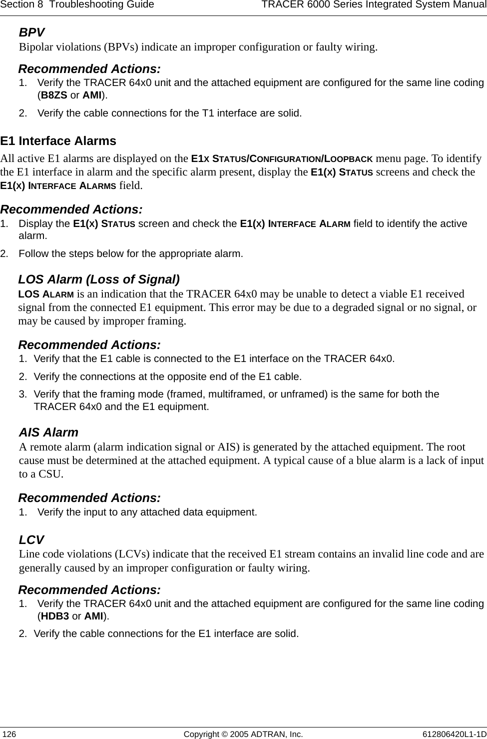
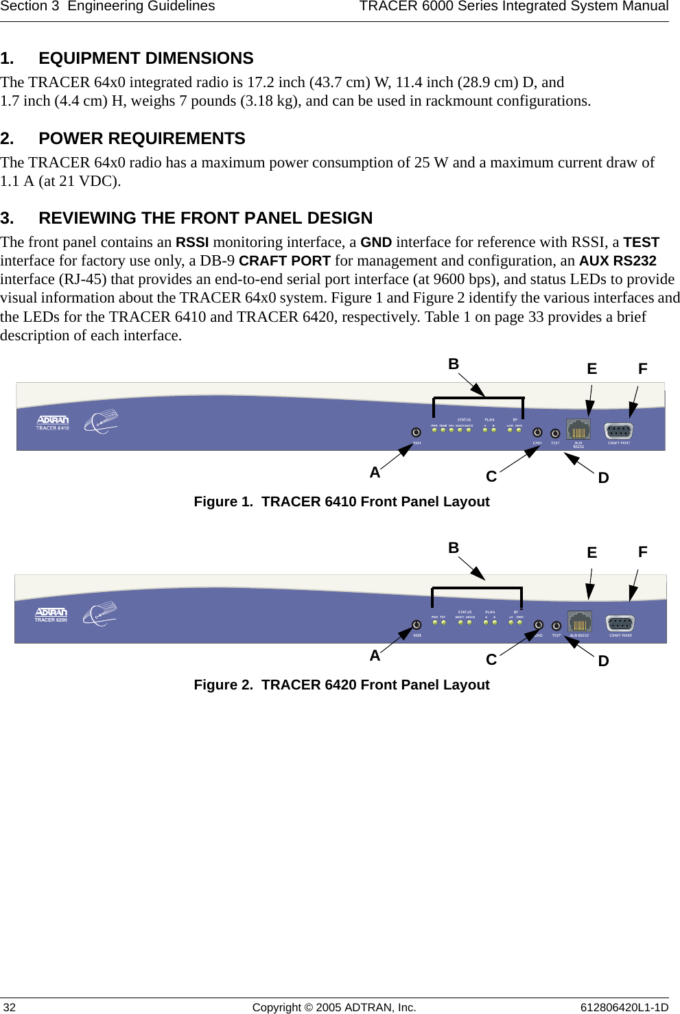
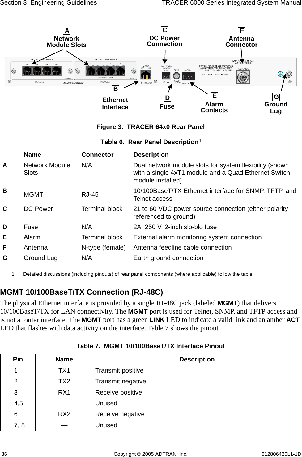
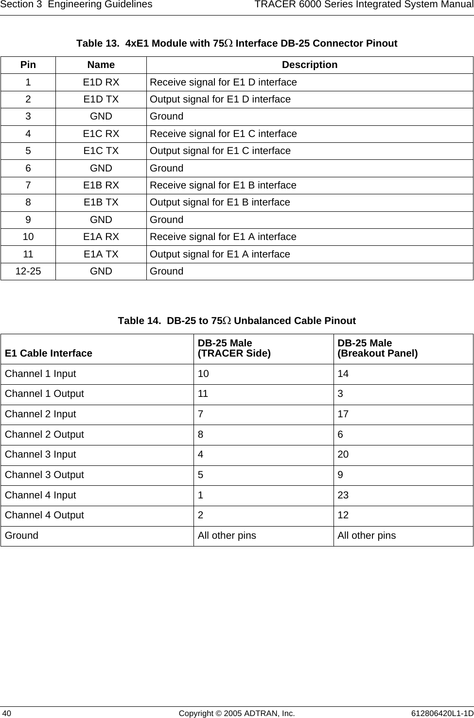
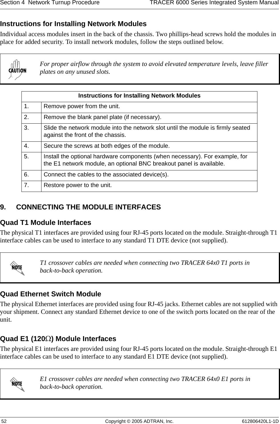
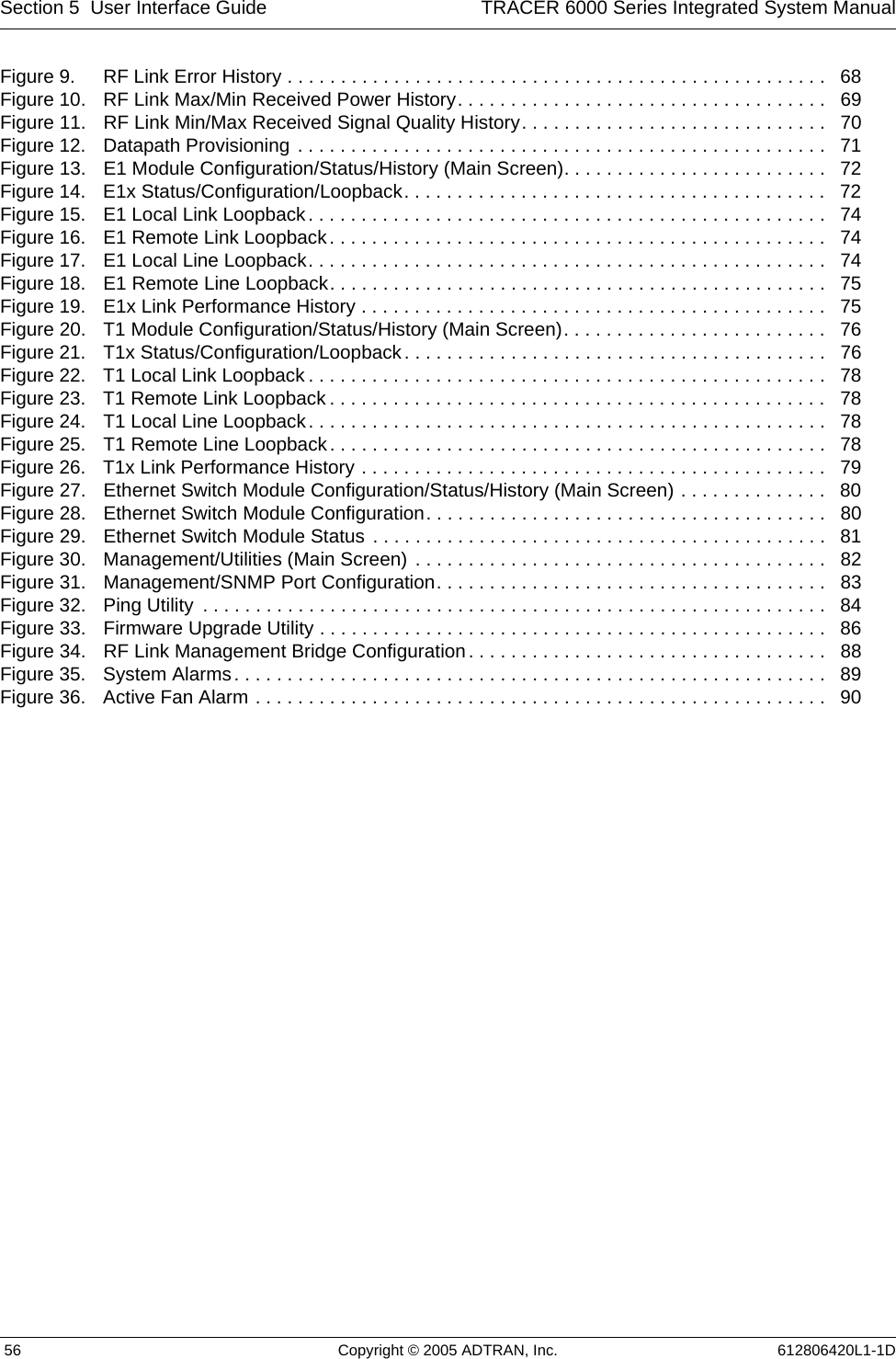
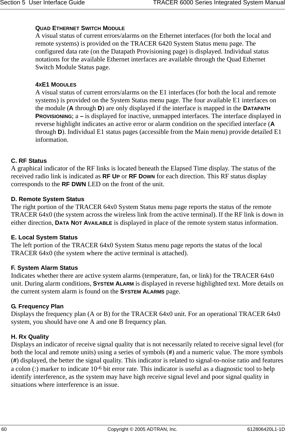
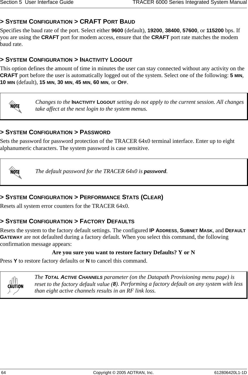
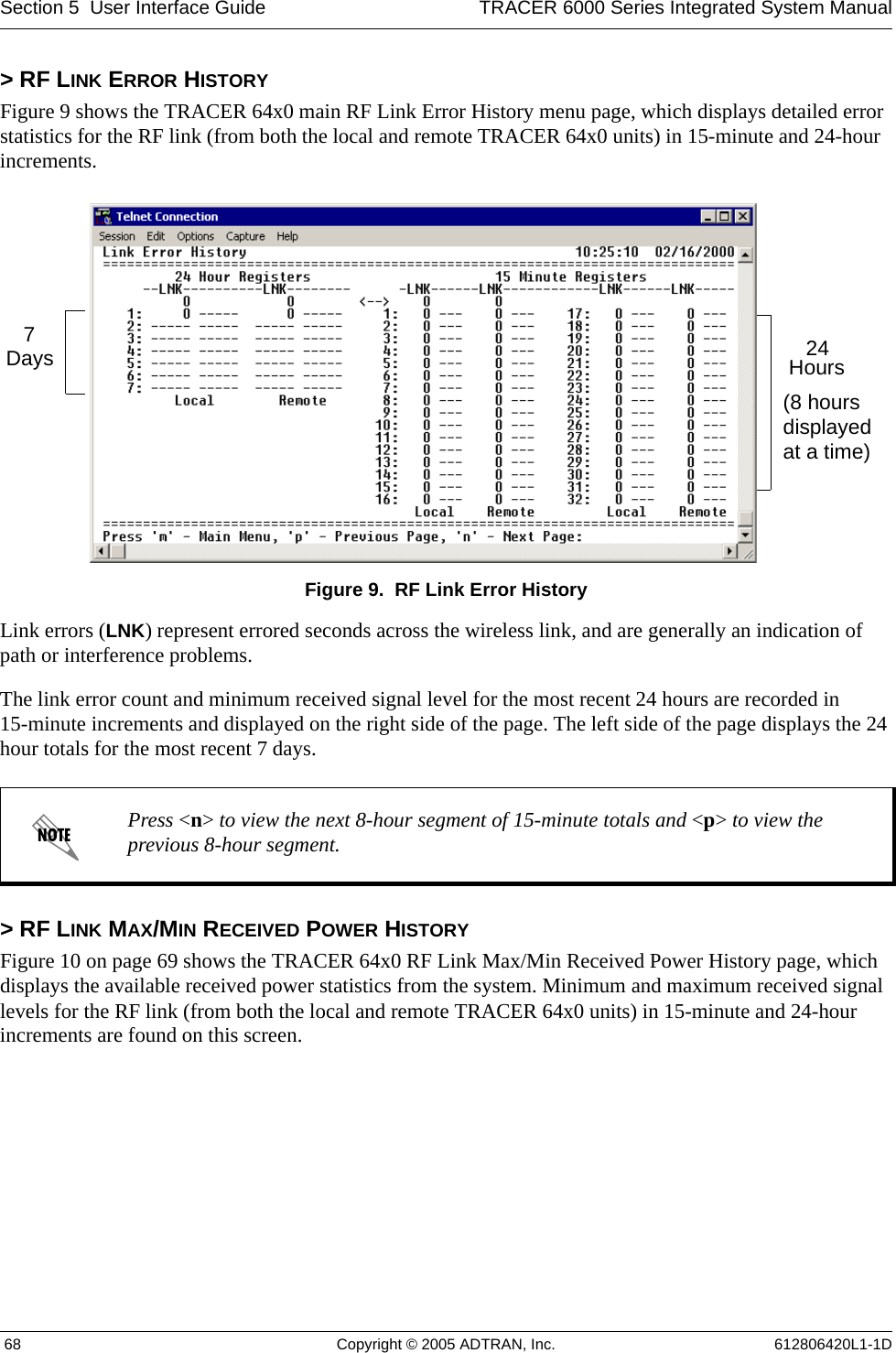
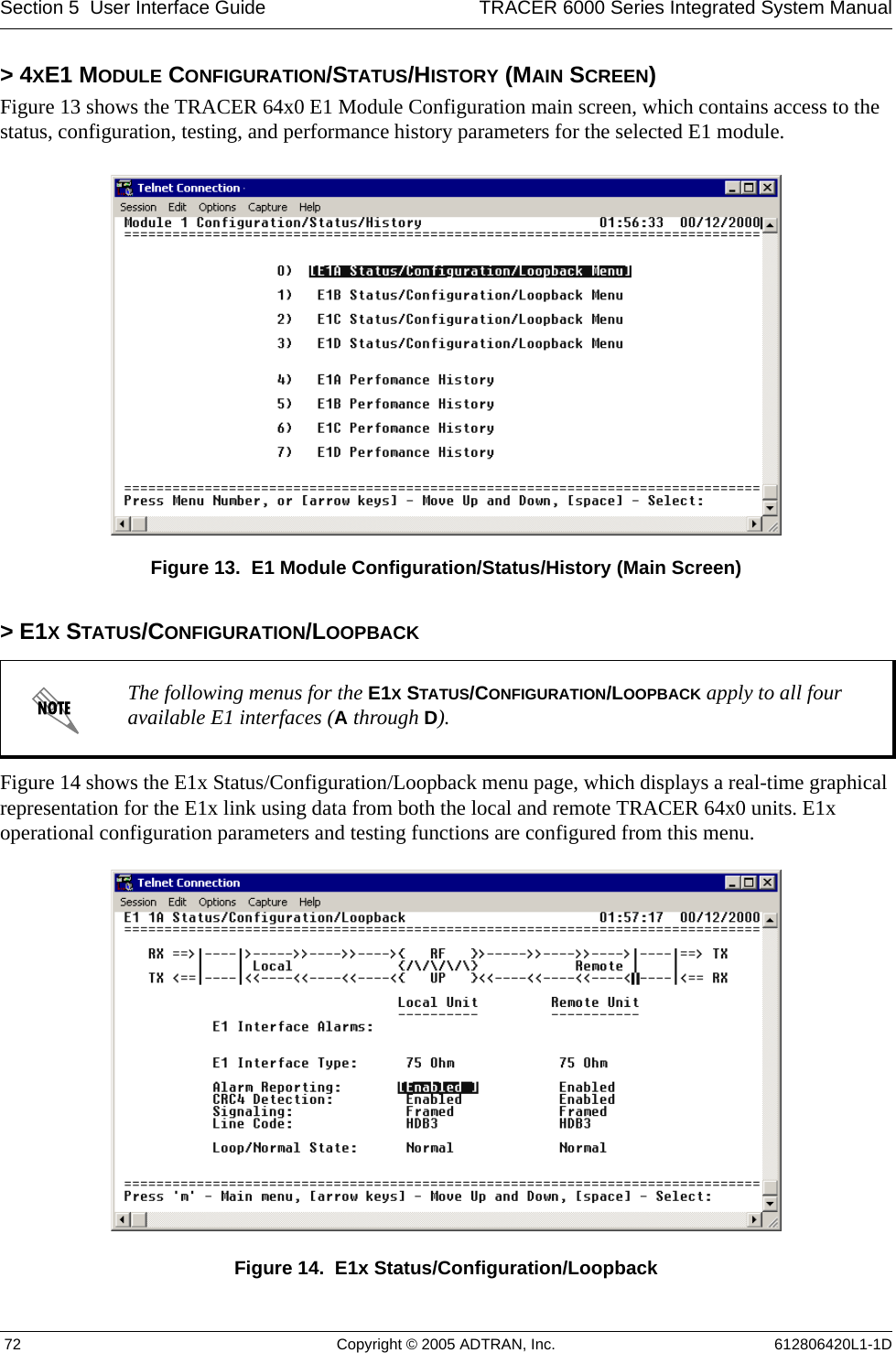
![TRACER 6000 Series Integrated System Manual Section 2 Microwave Path Engineering Basics612806420L1-1D Copyright © 2005 ADTRAN, Inc. 277. OTHER CONSIDERATIONSPath AvailabilityThe path availability of a wireless link is a metric that expresses the fractional amount of time a link is available over some fixed amount of time, and depends on several factors. Path availability is expressed aswhere the parameters areaterrain factor bclimate factor fcarrier frequency (GHz) dpath length (miles) Ffade margin (dB)orTable 11. Minimum Antenna Height for Given Path Lengths (km and m)Path Length(kilometers)Min. Antenna Heightat 2.4 GHz(meters)Min. Antenna Heightat 5.8 GHz(meters)28.0 5.1411.4 7.4614.2 9.3816.8 11.110 19.2 12.814 23.8 16.316 26.1 18.218 28.5 20.020 30.9 22.022 33.3 24.024 35.9 26.126 38.4 28.328 41.1 30.630 43.9 32.932 46.7 35.434 49.6 38.036 52.6 40.6A12.5106–×()abfd310 F10⁄–()–[]100%×=(%)A16.00 10 7–×()abfd310 F10⁄–()–[]100%×=(%)](https://usermanual.wiki/ADTRAN/TRC6410L2X/User-Guide-696397-Page-27.png)
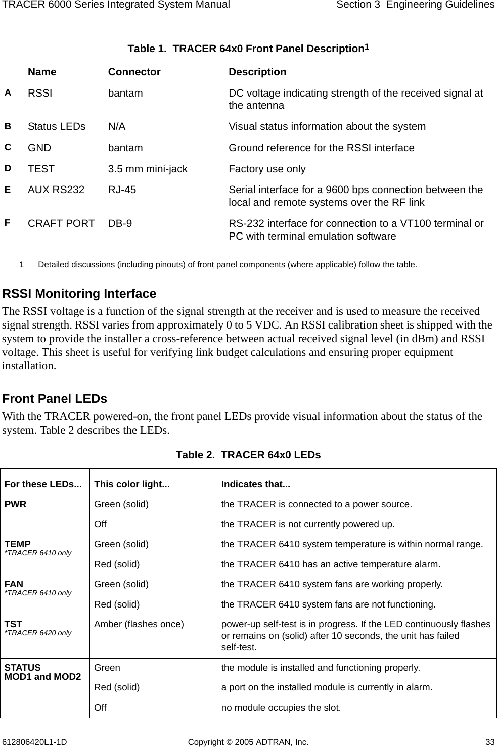
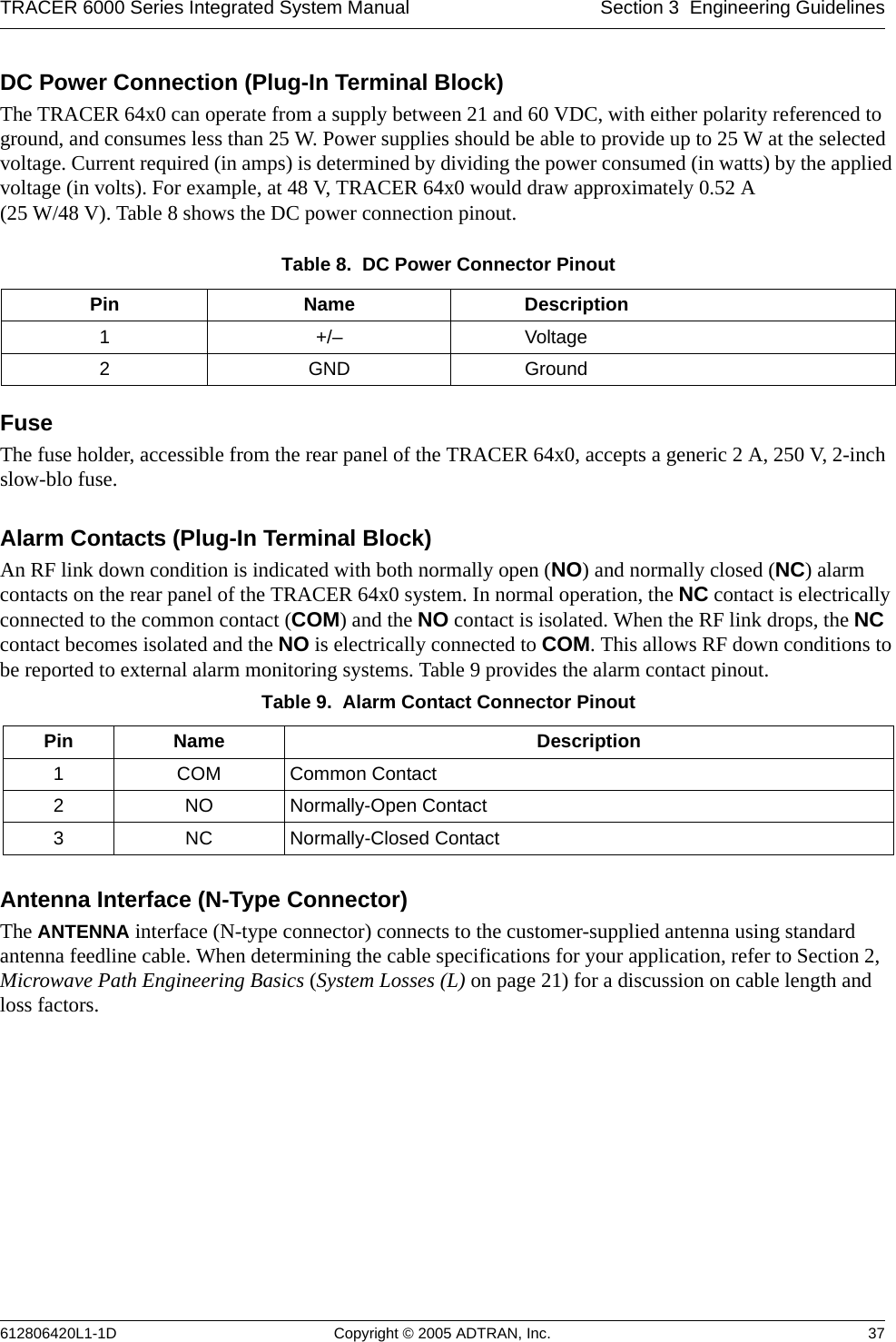
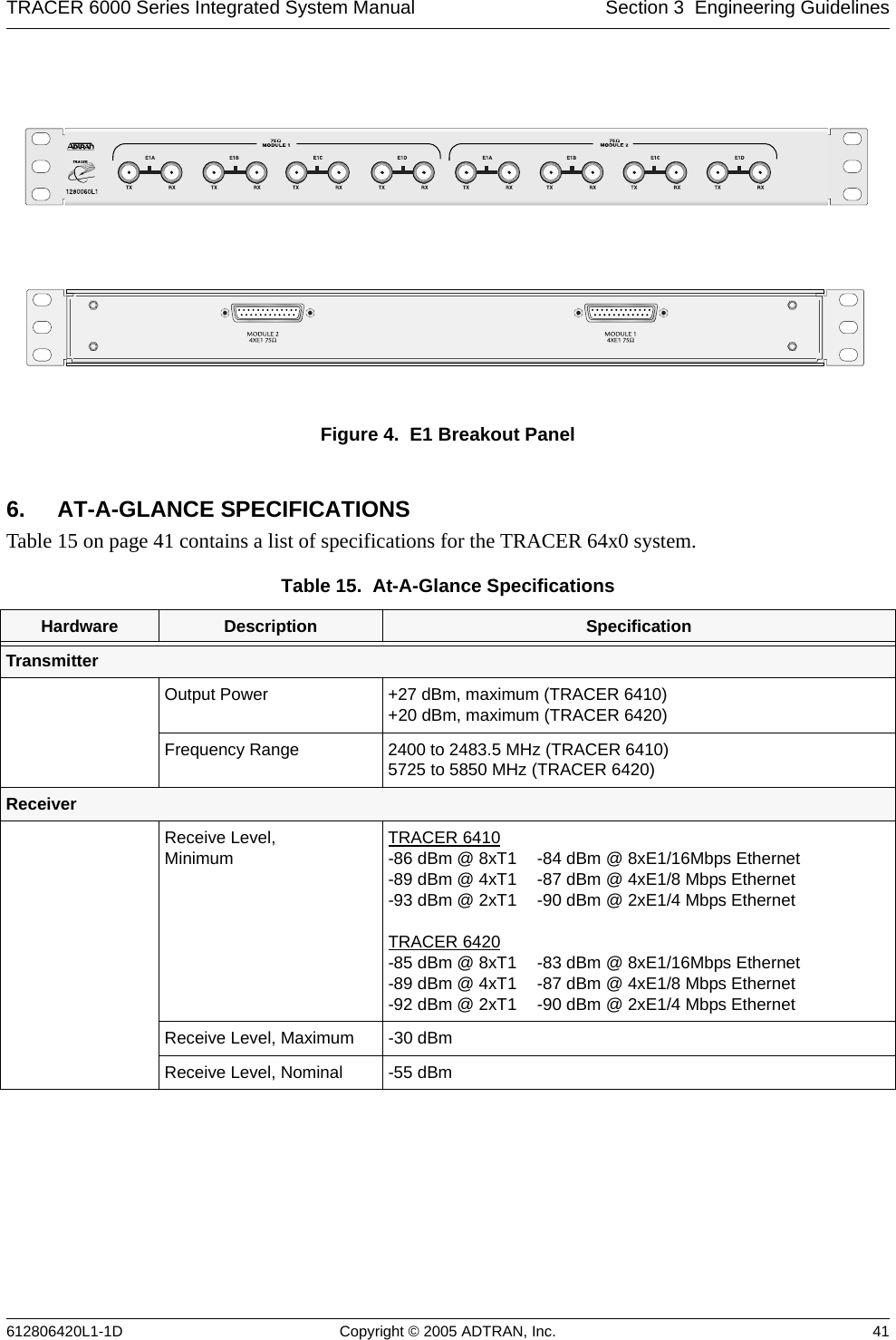
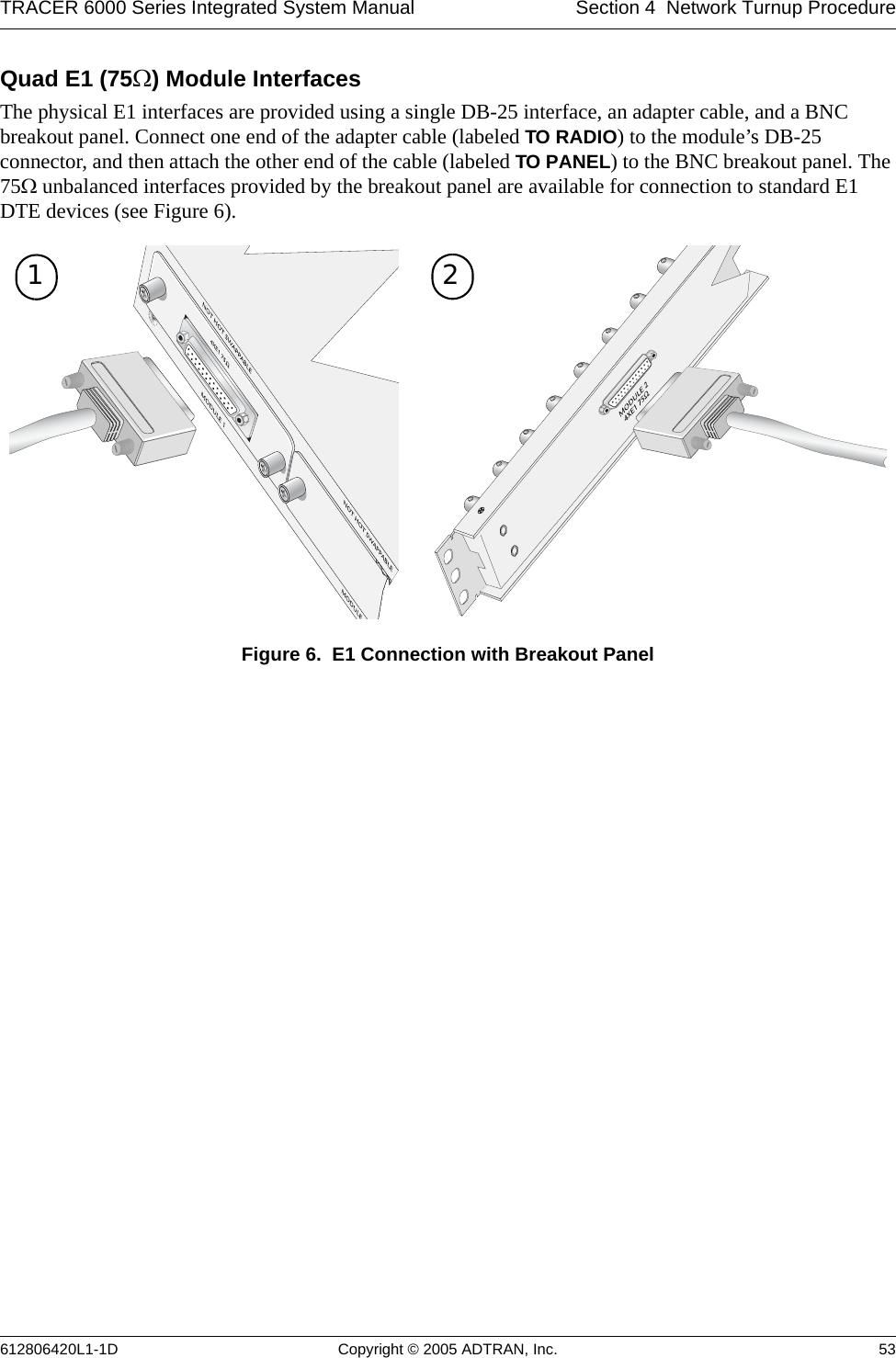
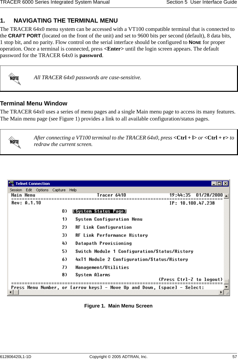
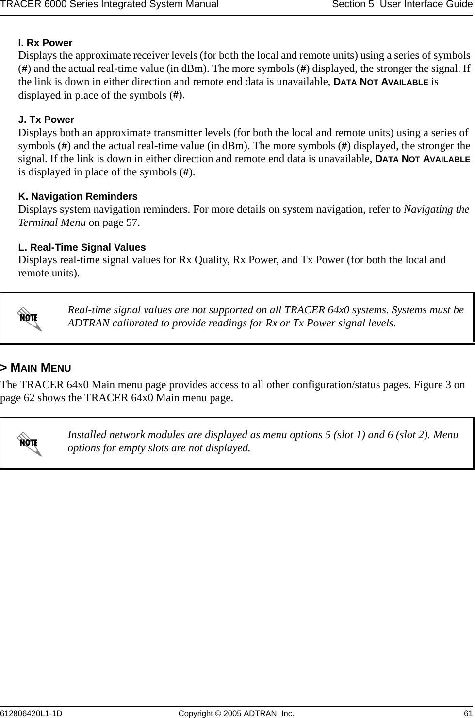
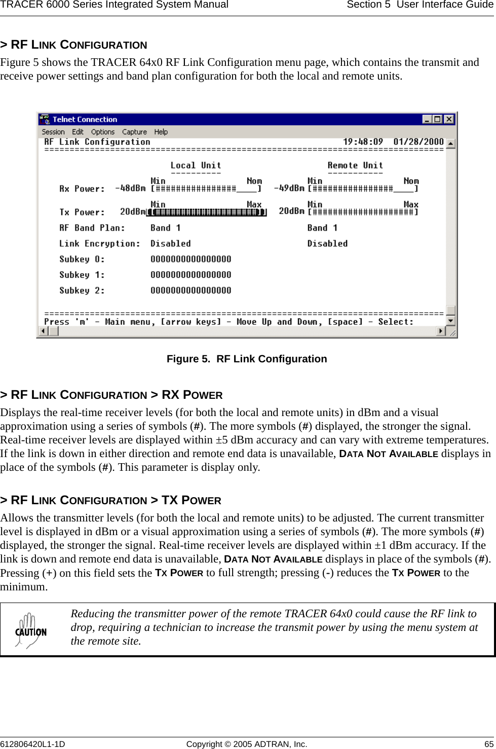
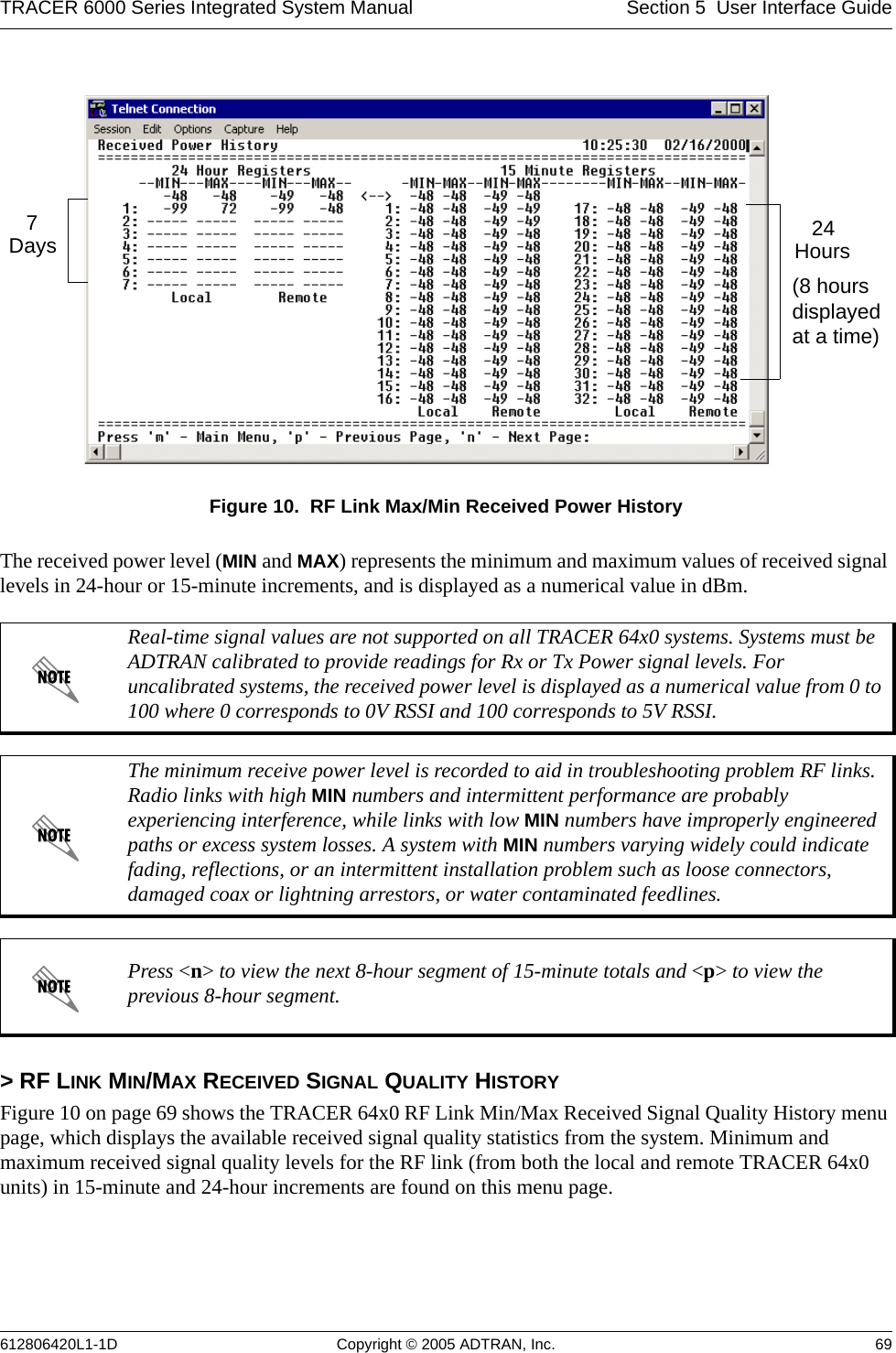
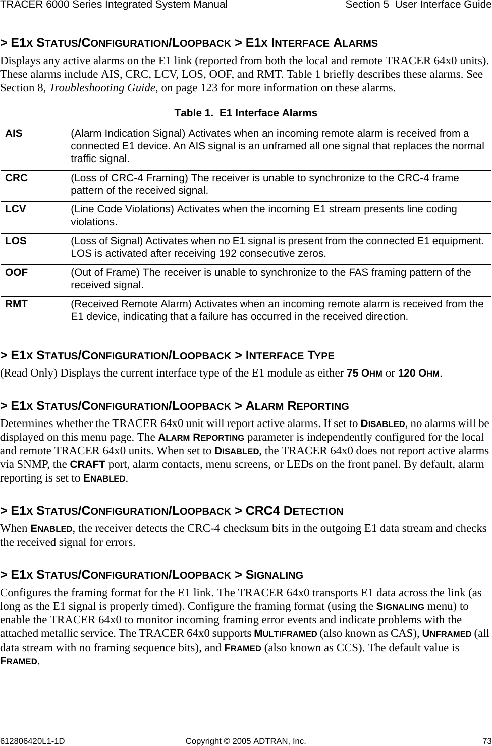
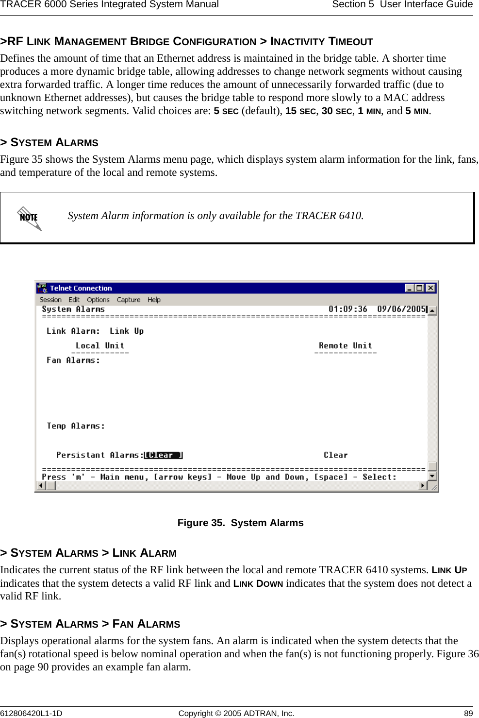
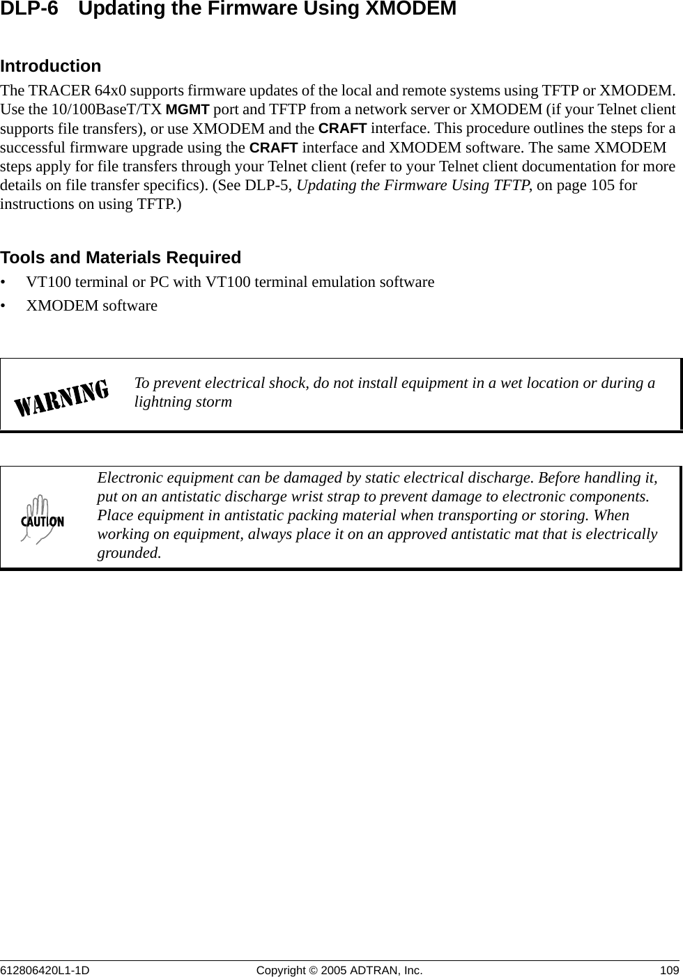
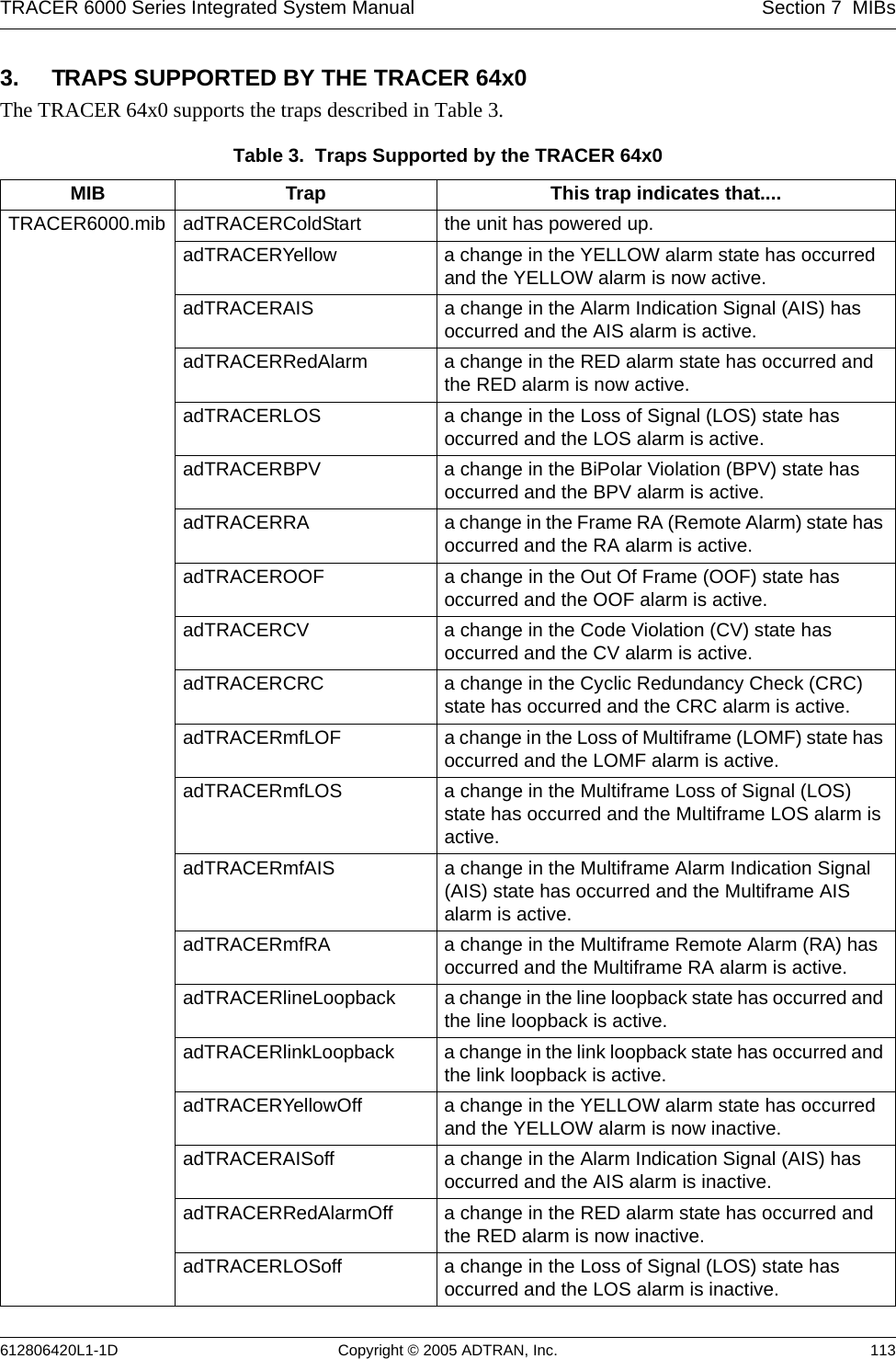
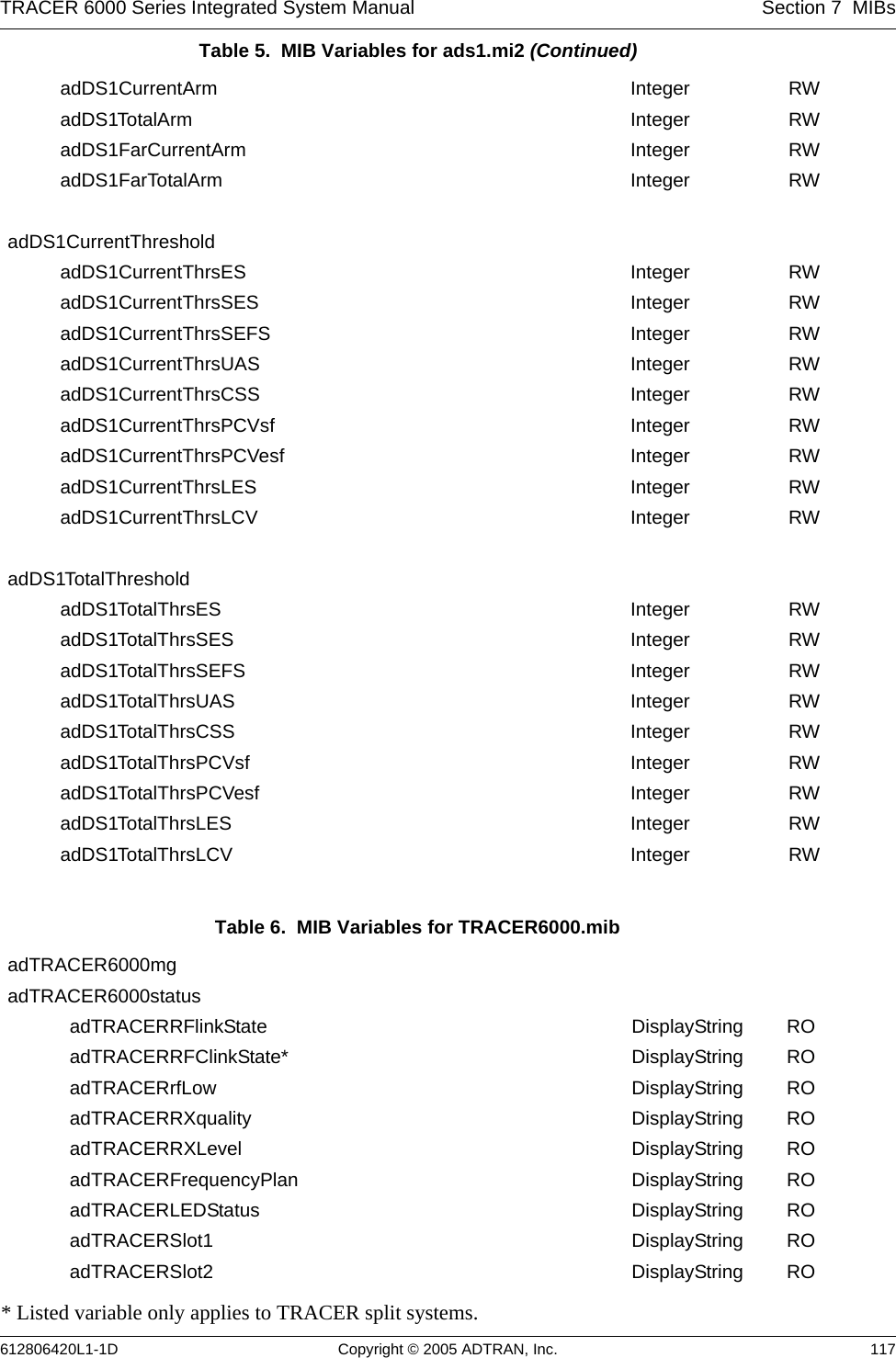
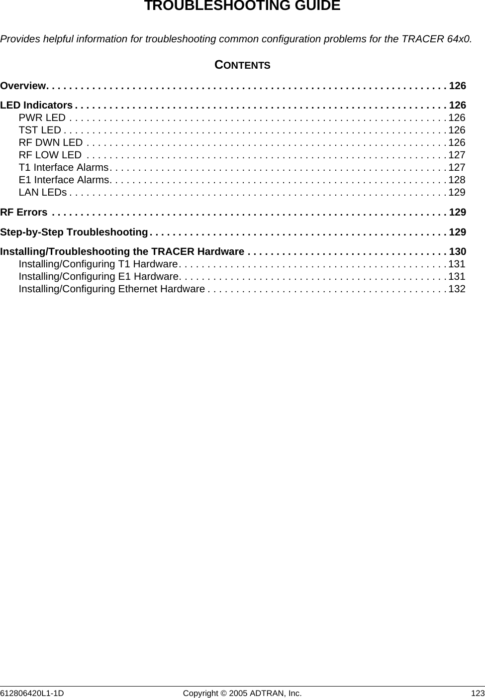
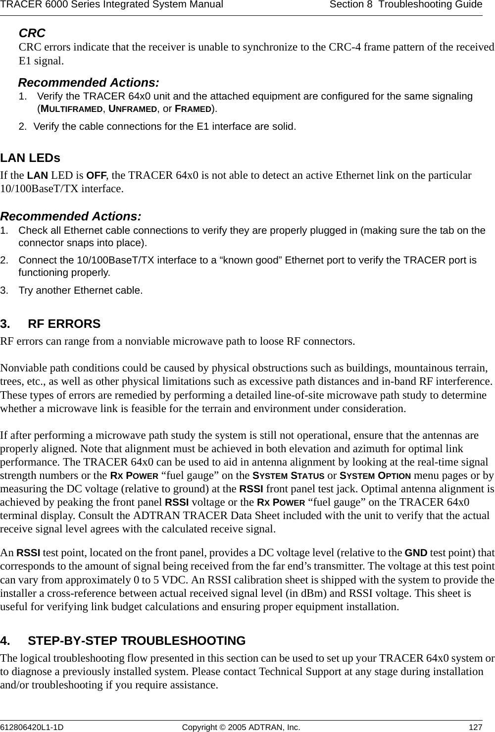
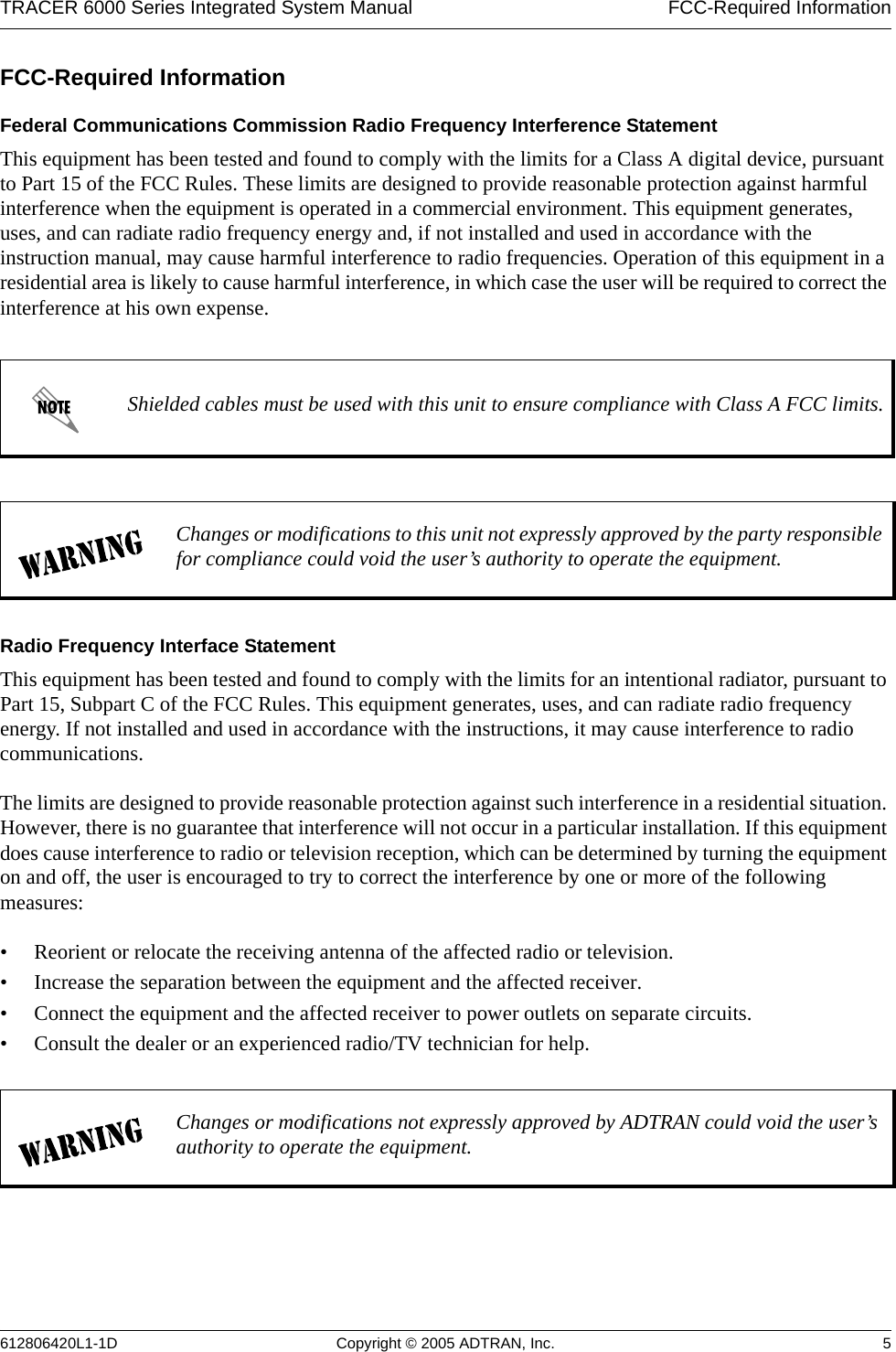
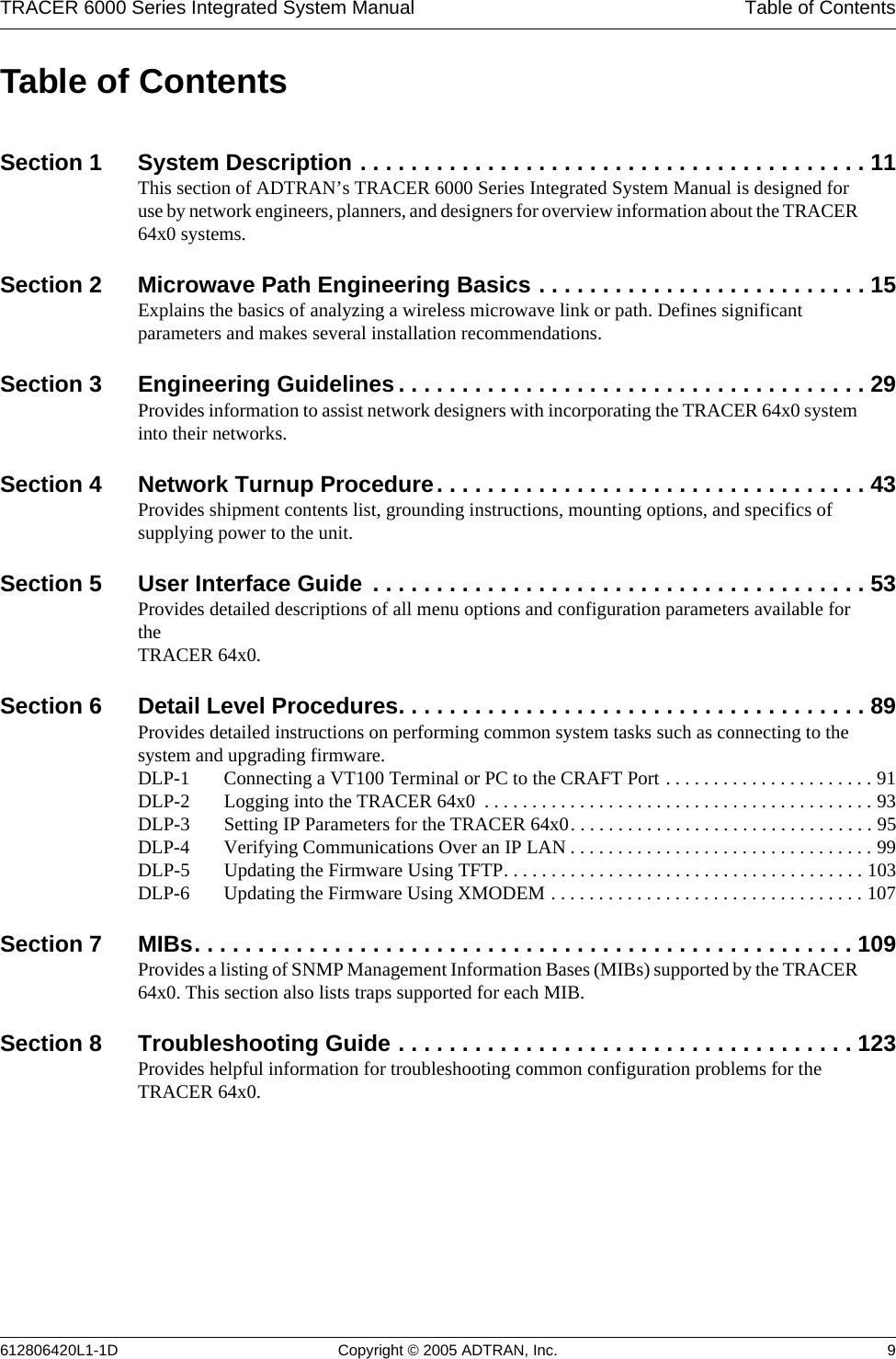
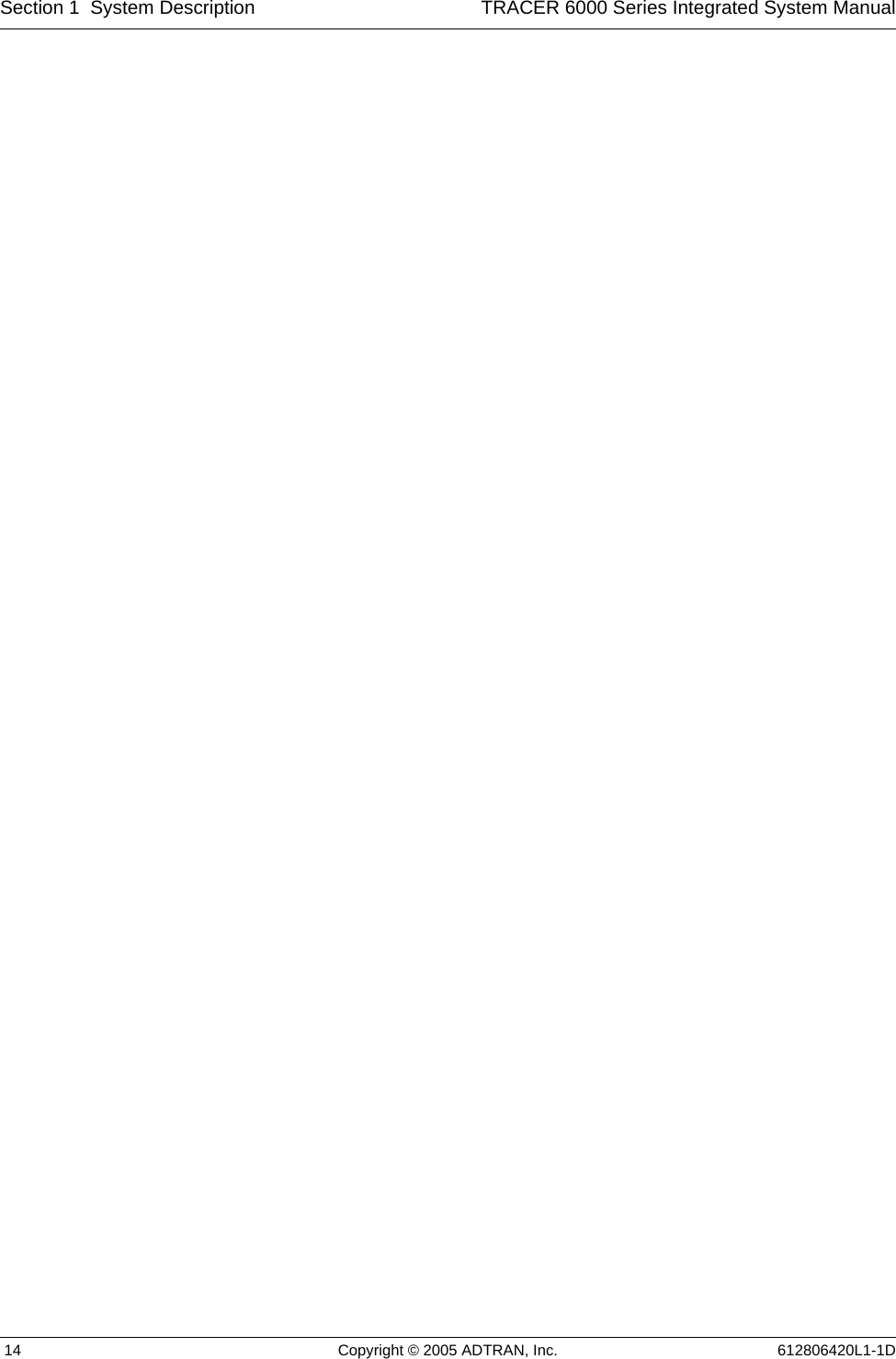
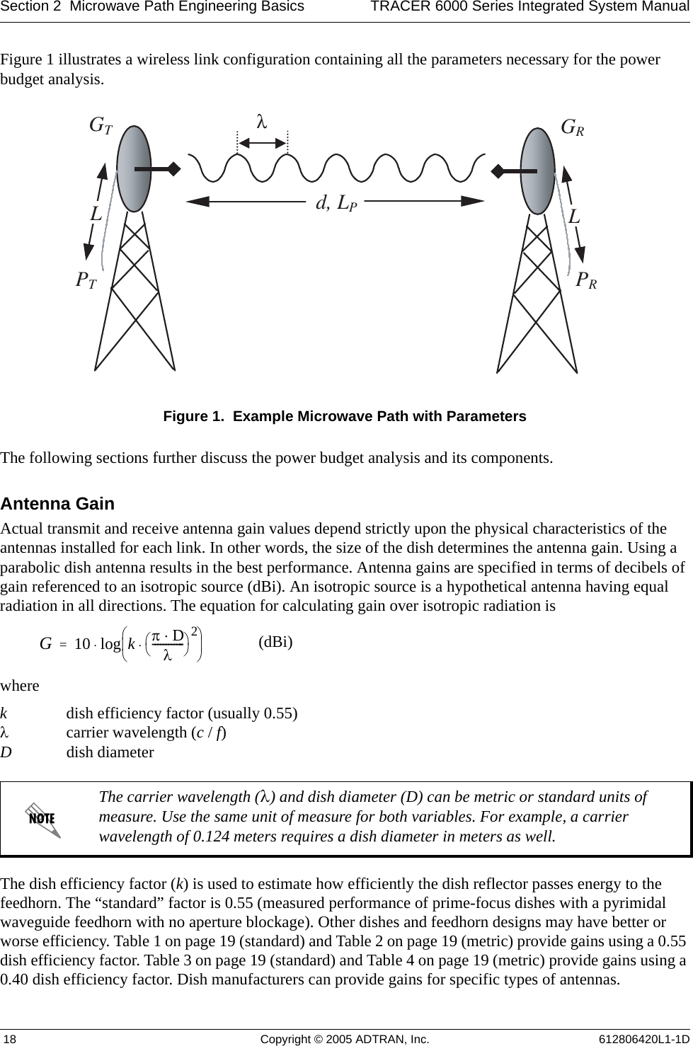
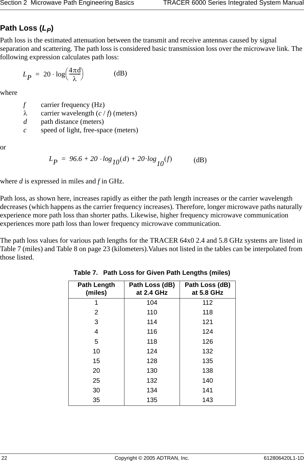
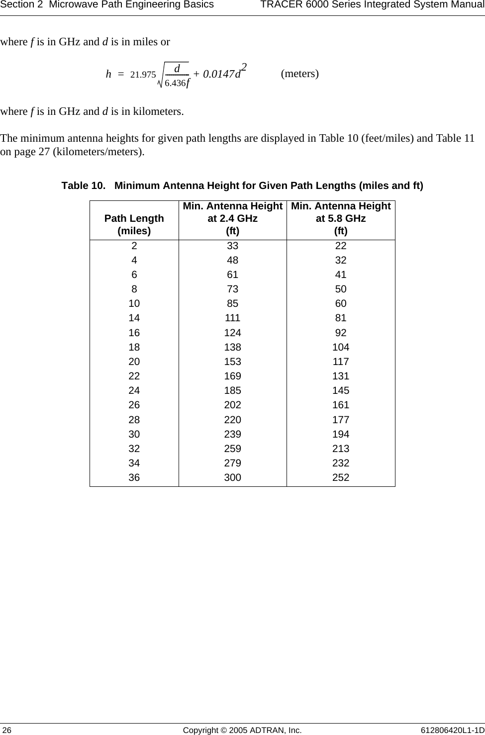
![Section 5 User Interface Guide TRACER 6000 Series Integrated System Manual 74 Copyright © 2005 ADTRAN, Inc. 612806420L1-1D> E1X STATUS/CONFIGURATION/LOOPBACK > LINE CODESets the line coding for the E1 link. The TRACER 64x0 supports high-density bipolar 3 substitution (HDB3) and alternate mark inversion (AMI) line coding. HDB3 coding does not allow more than three consecutive zeros in a transmitted bit stream and is the standard coding method on public networks. > E1X STATUS/CONFIGURATION/LOOPBACK > LOOP/NORMAL STATEControls the loop status of the E1 link. Activates/deactivates loopback conditions for testing purposes.> E1X STATUS/CONFIGURATION/LOOPBACK > LOOP/NORMAL STATE > NORMALDefines the E1 link as normal data transport mode; there are no active loopbacks.> E1X STATUS/CONFIGURATION/LOOPBACK > LOOP/NORMAL STATE > LINK [LOCAL]Activates a loopback at the local TRACER 64x0 E1 framer towards the remote end of the wireless link (see Figure 15). Use the local LINK loopback to loop the data transmitted from the remote end of the link back across the radio link to the remote end of the link. This loopback tests the integrity of the radio link and all the associated digital and RF hardware.Figure 15. E1 Local Link Loopback> E1X STATUS/CONFIGURATION/LOOPBACK > LOOP/NORMAL STATE > LINK [REMOTE]Activates a loopback at the remote TRACER 64x0 E1 framer towards the local end of the wireless link (see Figure 16). Use the remote LINK loopback to loop the data transmitted from the local end of the link across the radio link to the local end of the link. This loopback tests the integrity of the radio link and all the associated digital and RF hardware.Figure 16. E1 Remote Link Loopback> E1X STATUS/CONFIGURATION/LOOPBACK > LOOP/NORMAL STATE > LINE [LOCAL]Activates a loopback at the local TRACER 64x0 E1 framer towards the locally connected E1 equipment (see Figure 17). Use the local LINE loopback to test data path integrity from the local TRACER 64x0 unit to the connected E1 equipment.Figure 17. E1 Local Line Loopback](https://usermanual.wiki/ADTRAN/TRC6410L2X/User-Guide-696397-Page-72.png)
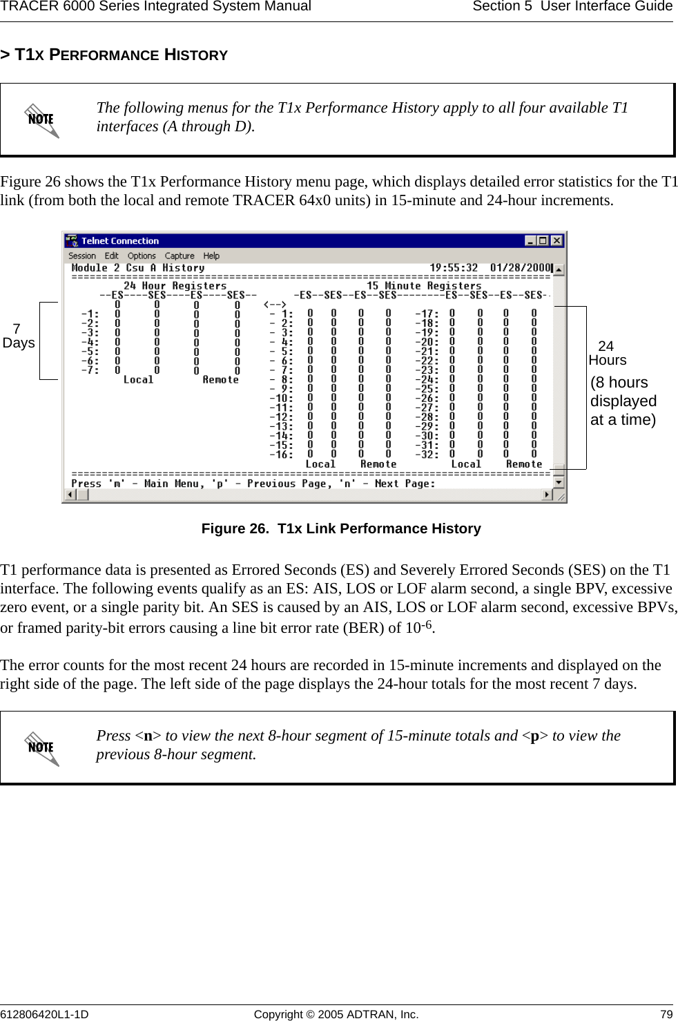
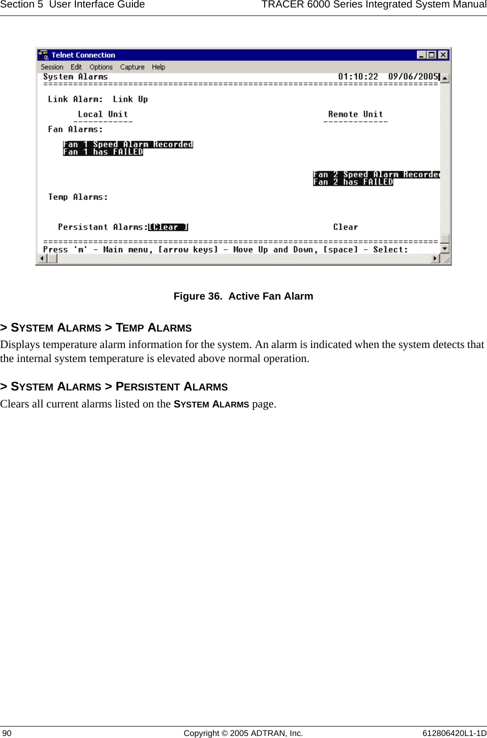
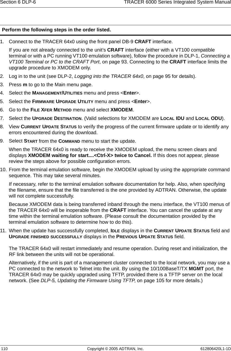
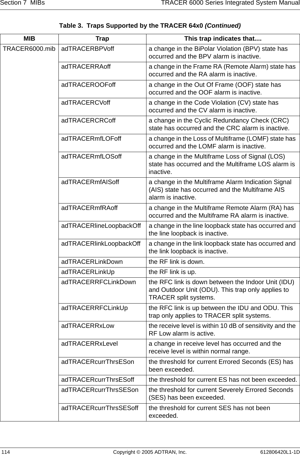
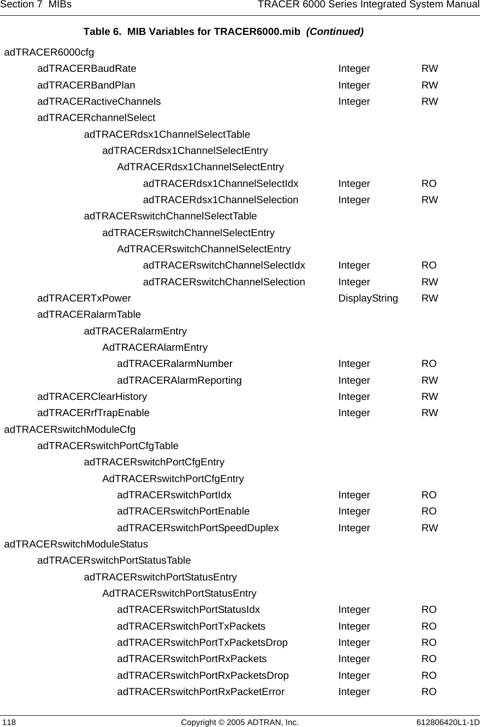
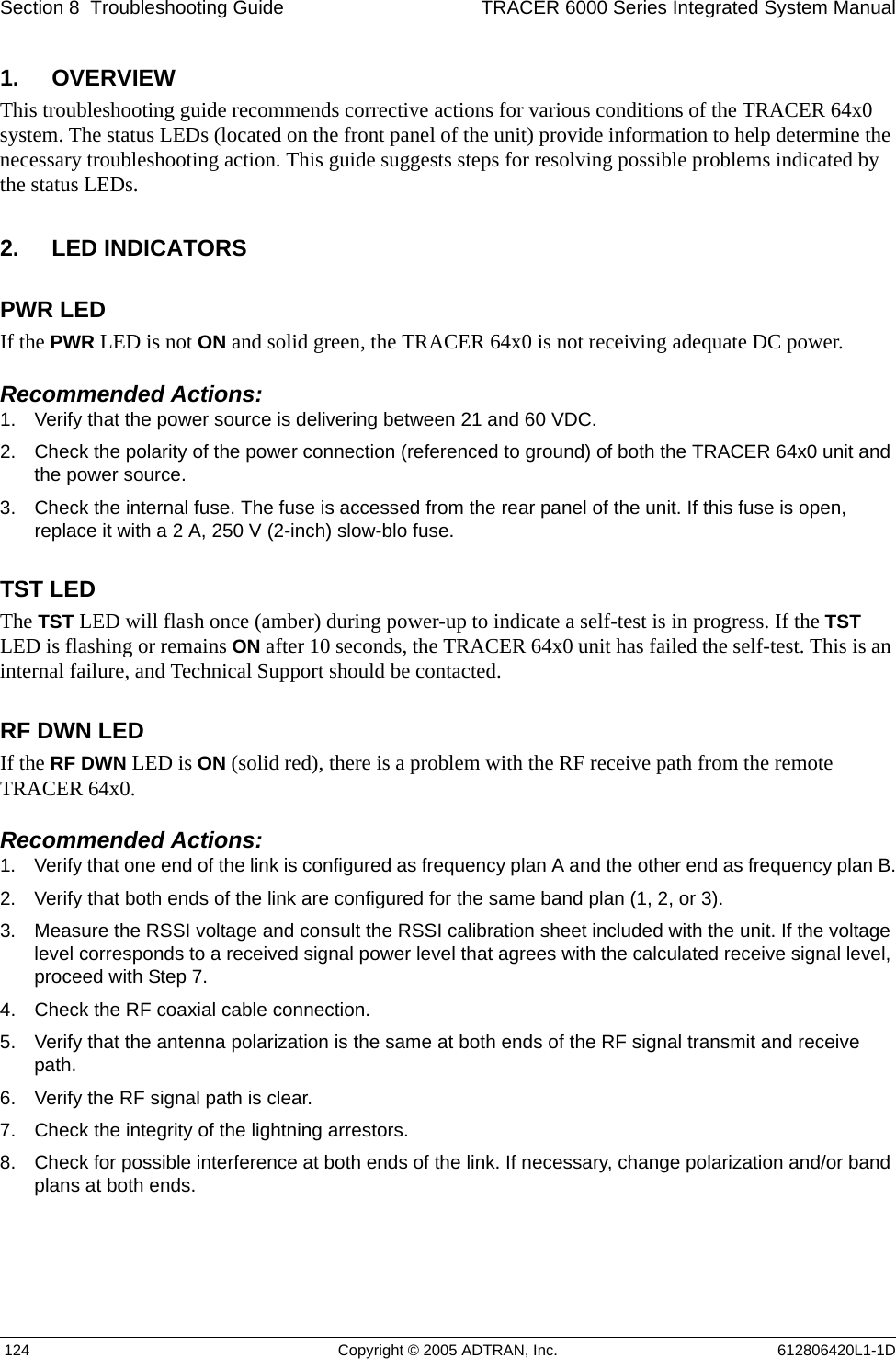
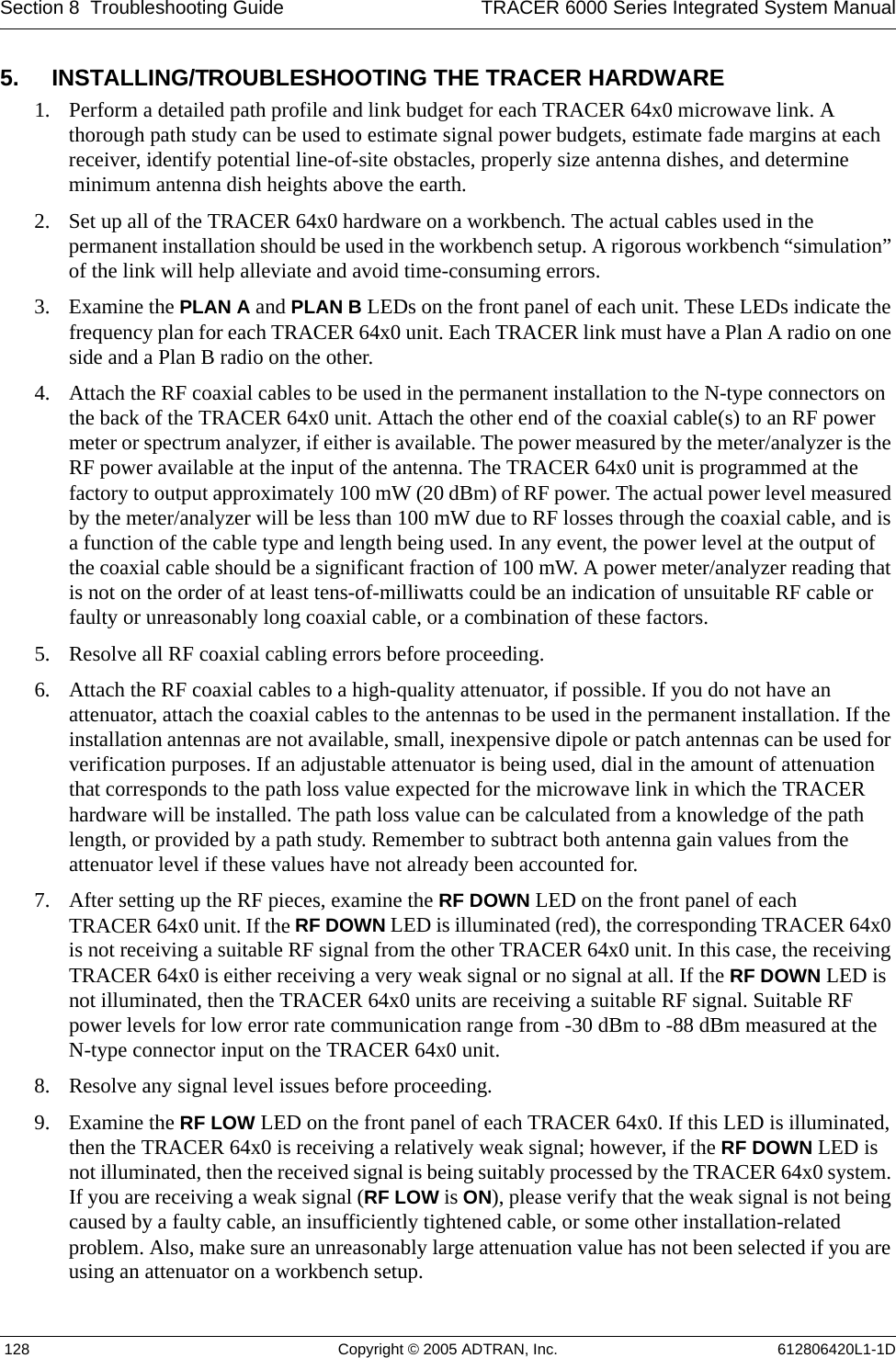
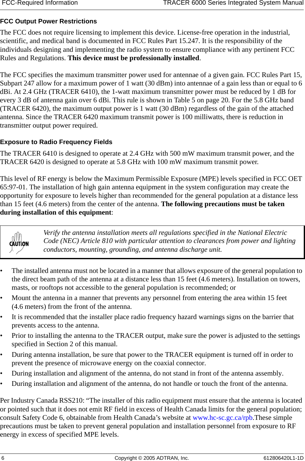
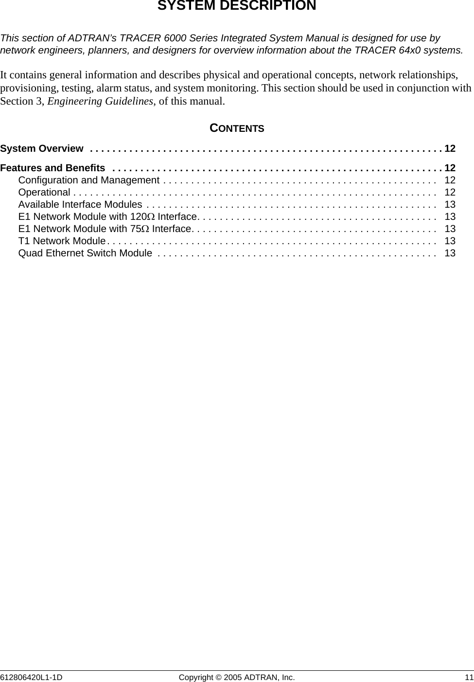
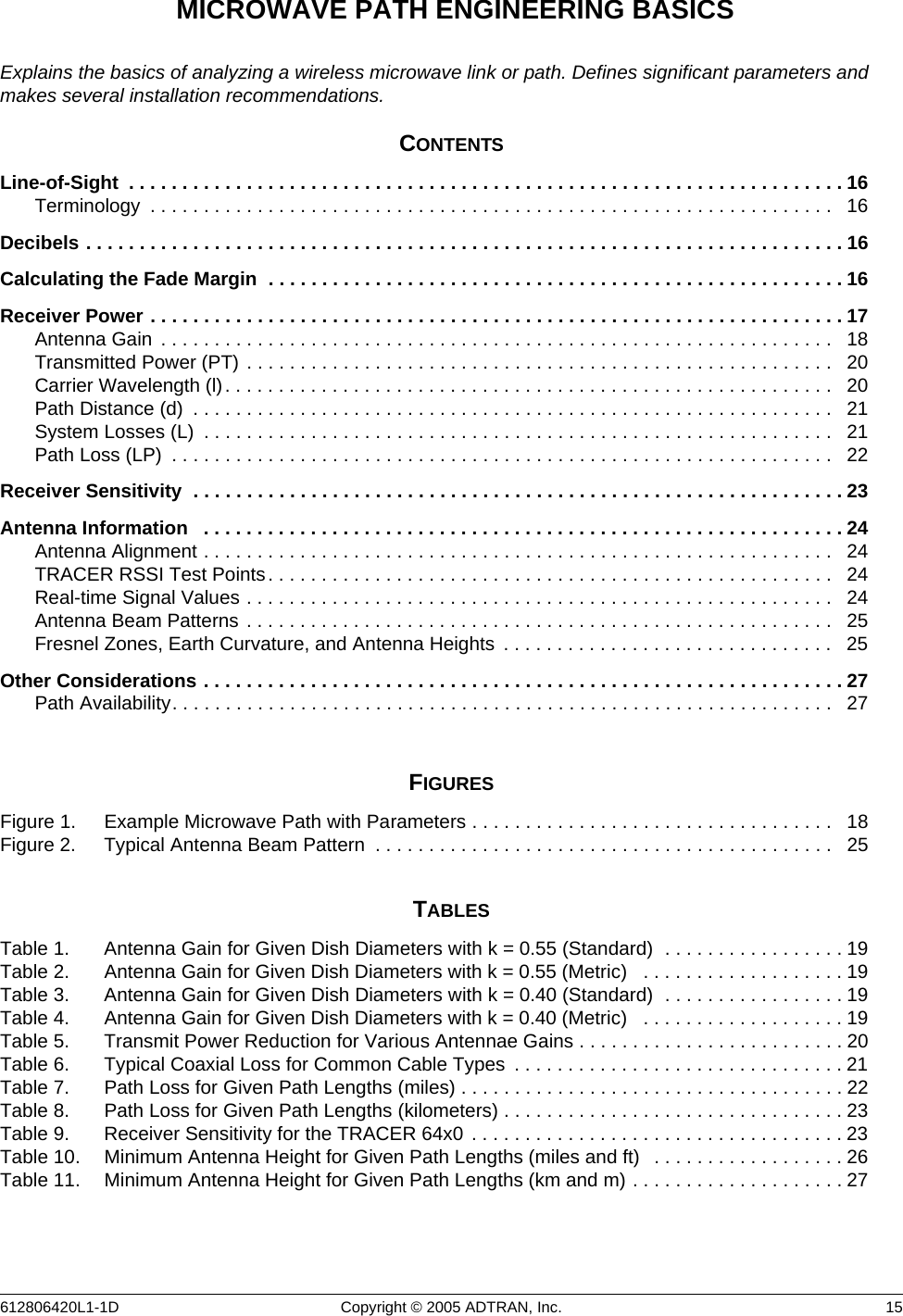
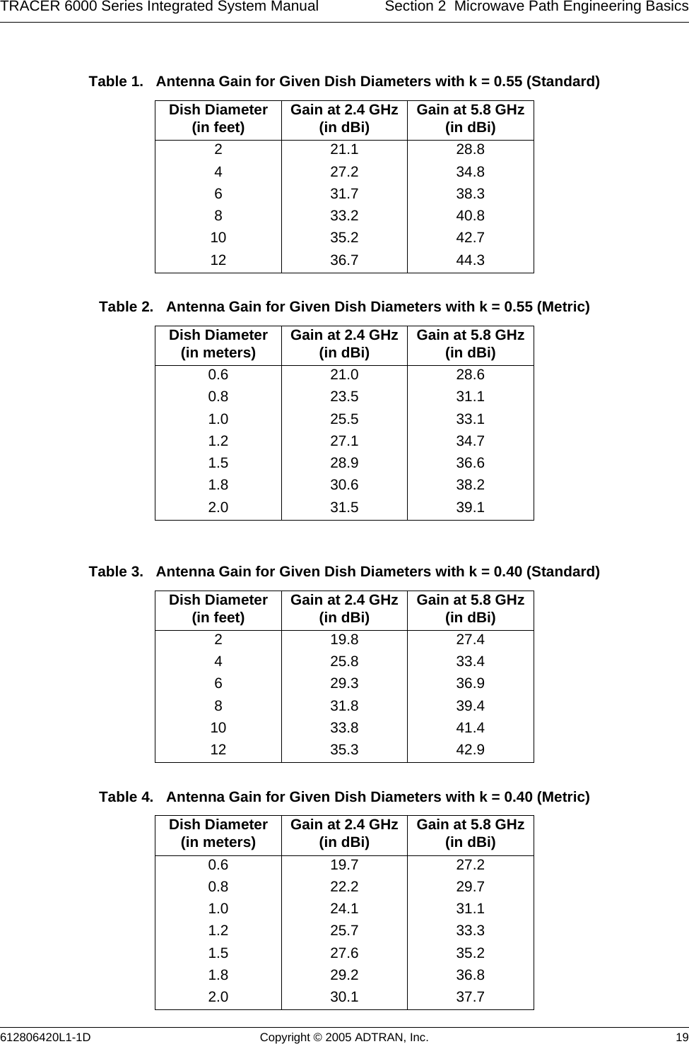
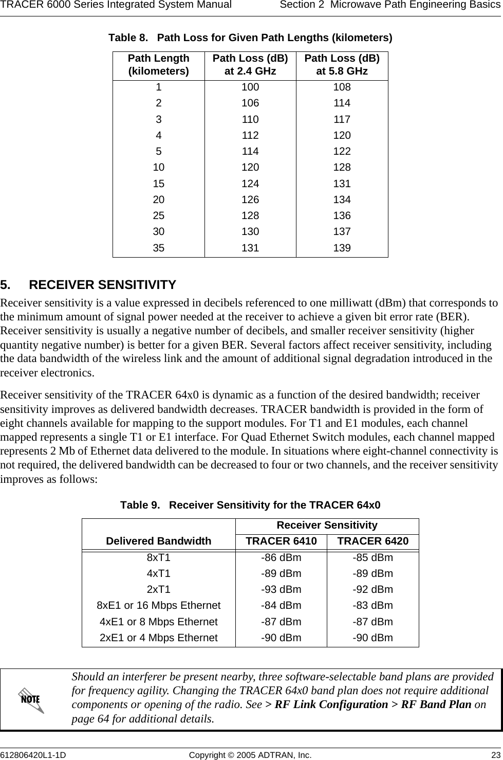
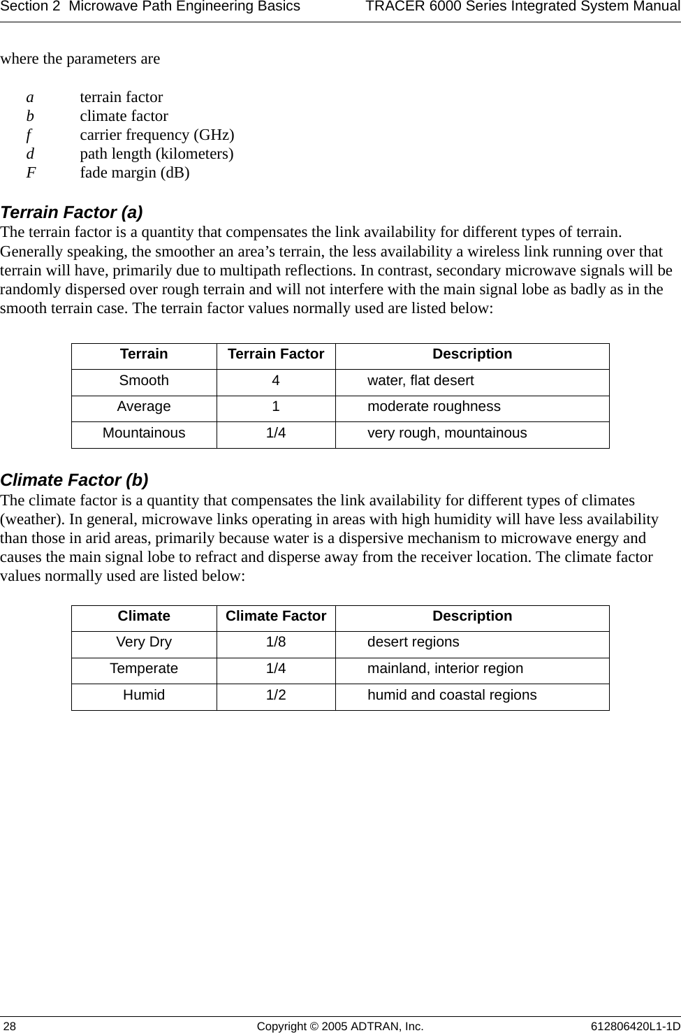
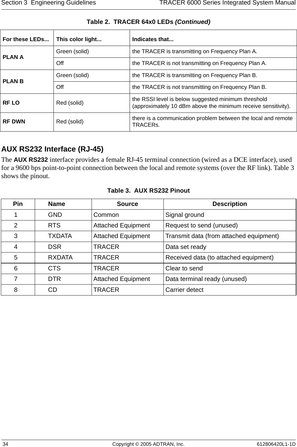
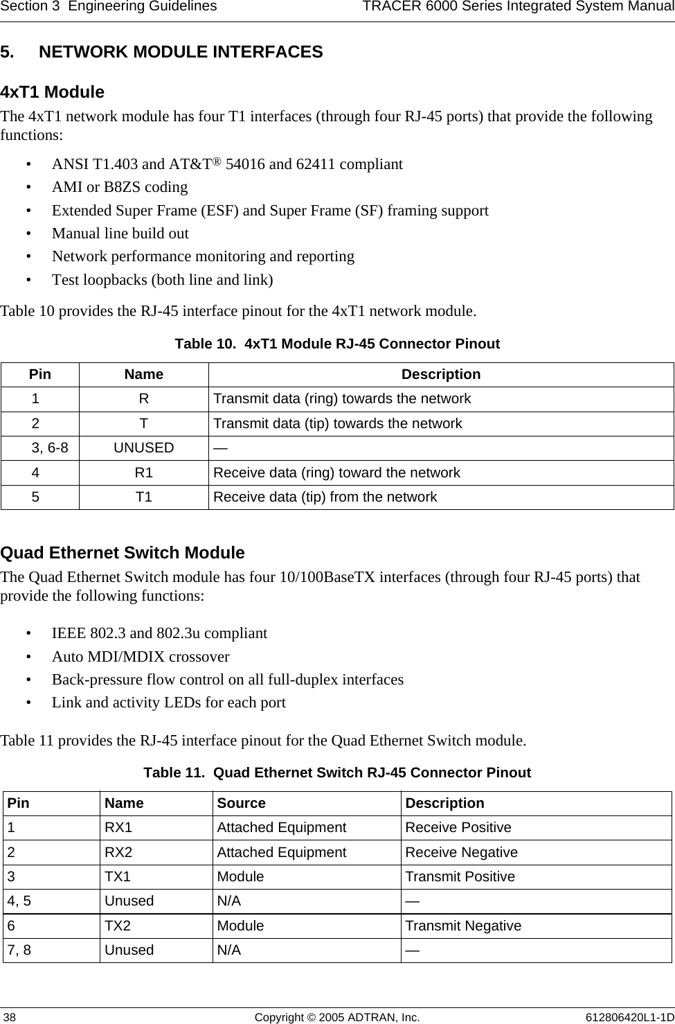
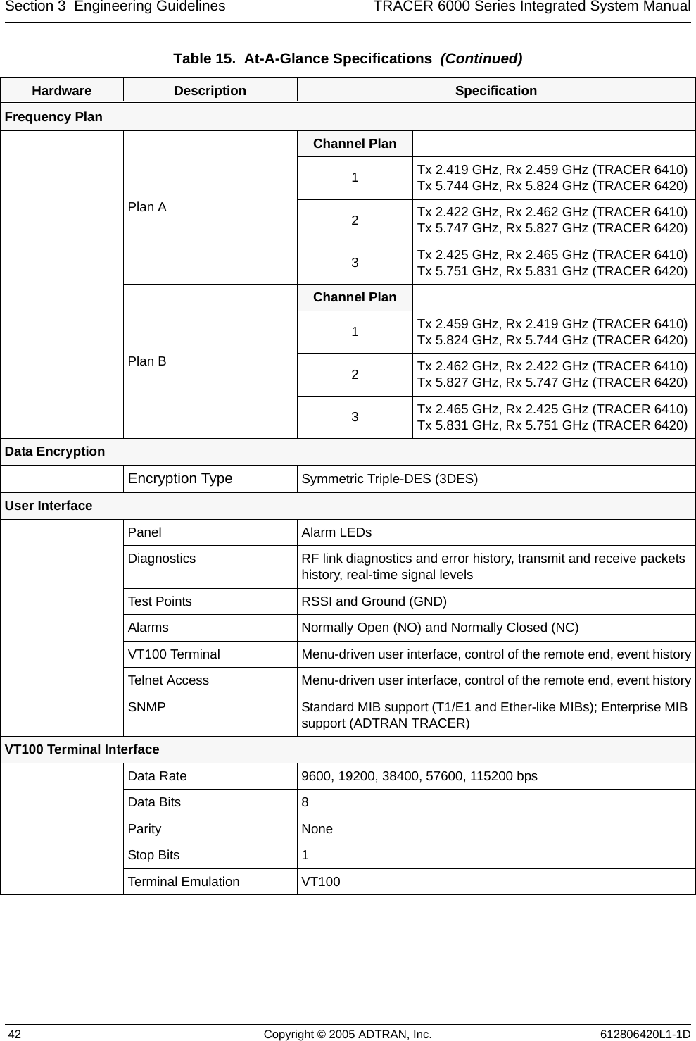
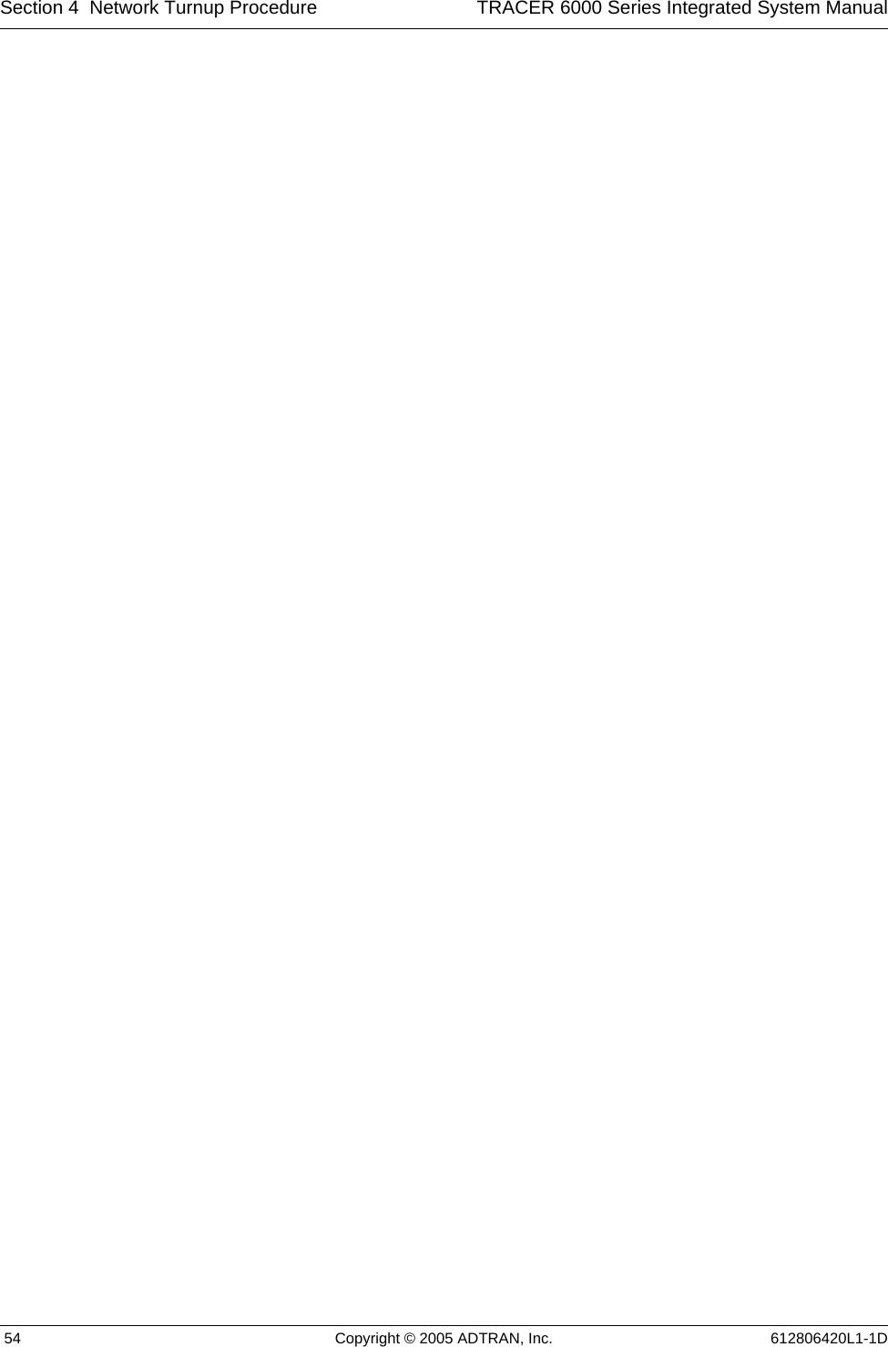
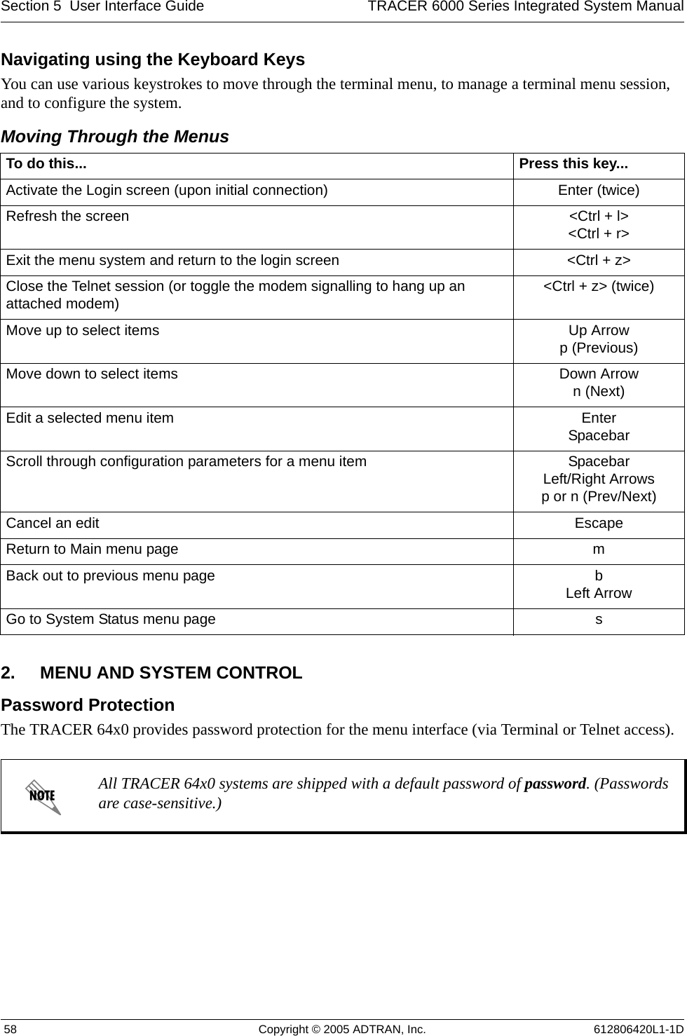
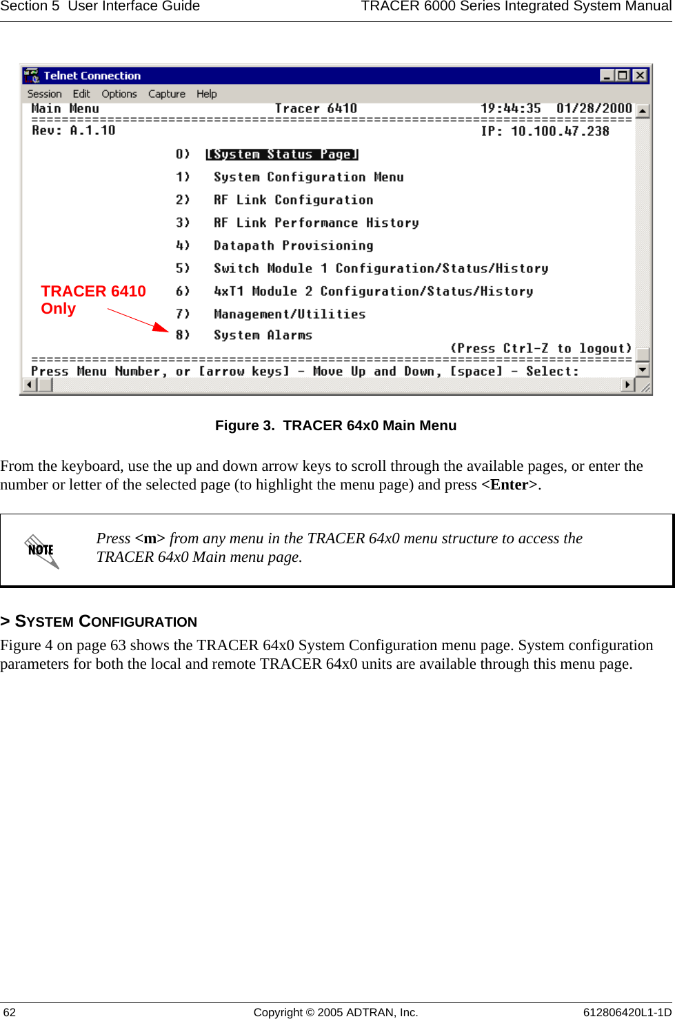
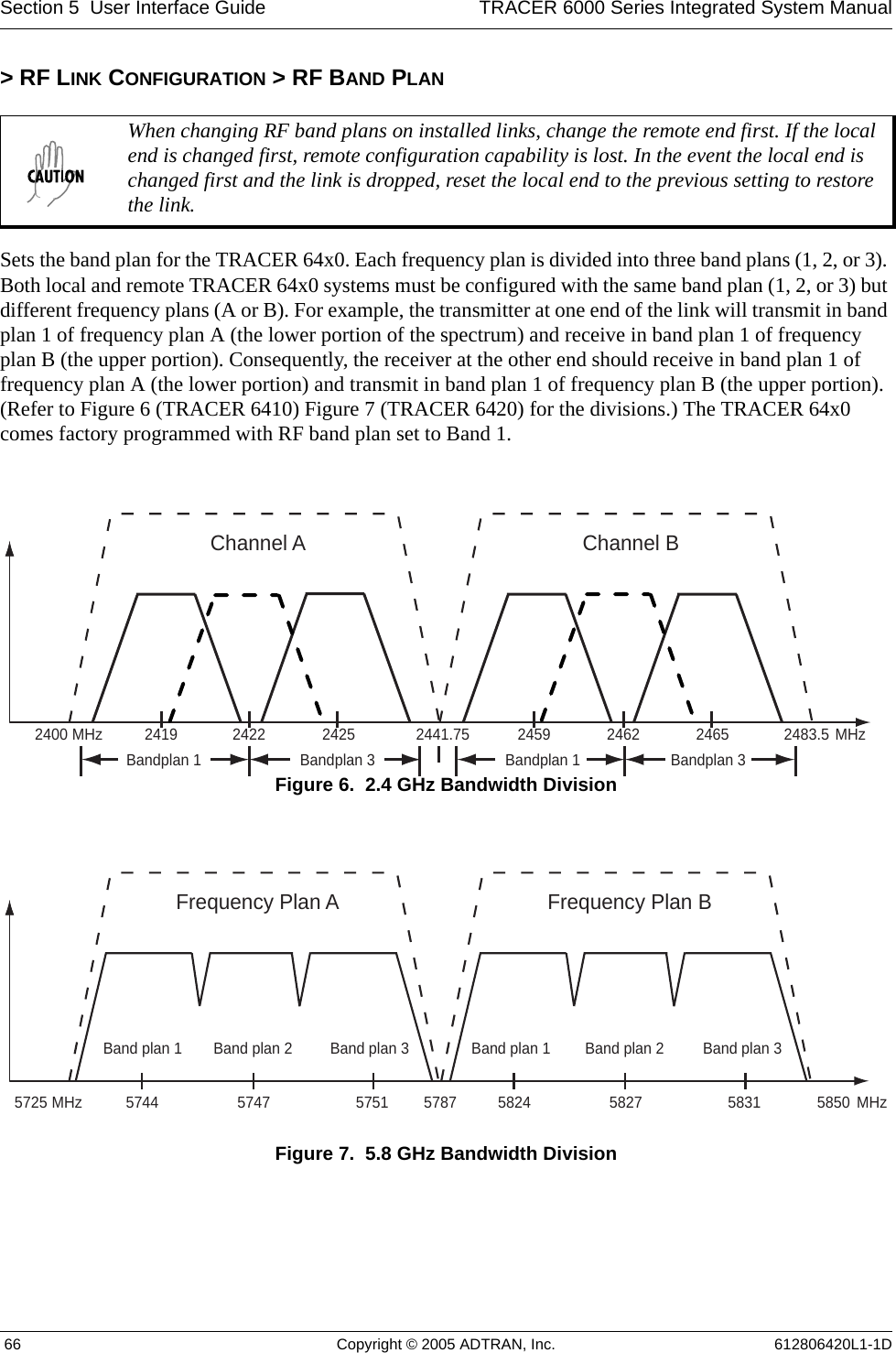
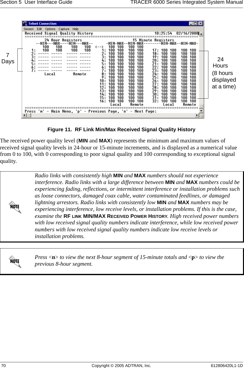
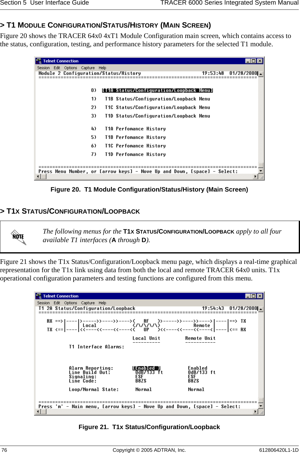
![TRACER 6000 Series Integrated System Manual Section 5 User Interface Guide612806420L1-1D Copyright © 2005 ADTRAN, Inc. 75> E1X STATUS/CONFIGURATION/LOOPBACK > LOOP/NORMAL STATE > LINE [REMOTE]Activates a loopback at the remote TRACER 64x0 E1 framer towards the connected E1 equipment at the remote end of the link (see Figure 18). Use the remote LINE loopback to test data path integrity from the remote TRACER 64x0 unit to the E1 equipment connected at the remote end of the link.Figure 18. E1 Remote Line Loopback> E1X PERFORMANCE HISTORYFigure 19 shows the E1x Performance History menu page, which displays detailed error statistics for the E1 link (from both the local and remote TRACER 64x0 units) in 15-minute and 24-hour increments. Figure 19. E1x Link Performance HistoryE1 performance data is presented as Errored Seconds (ES) and Severely Errored Seconds (SES) on the E1 interface. The following events qualify as an ES: LOS, OOF, LCV, or CRC error. An SES is caused by a loss of signal or an out-of-frame event.The error count for the most recent 24 hours are recorded in 15-minute increments and displayed on the right side of the page. The left side of the page displays the 24-hour totals for the most recent 7 days.The following menus for the E1X PERFORMANCE HISTORY apply to all four available E1 interfaces (A through D).Press <n> to view the next 8-hour segment of 15-minute totals and <p> to view the previous 8-hour segment.7 Days24Hours(8 Hoursdisplayedat a time)](https://usermanual.wiki/ADTRAN/TRC6410L2X/User-Guide-696397-Page-73.png)
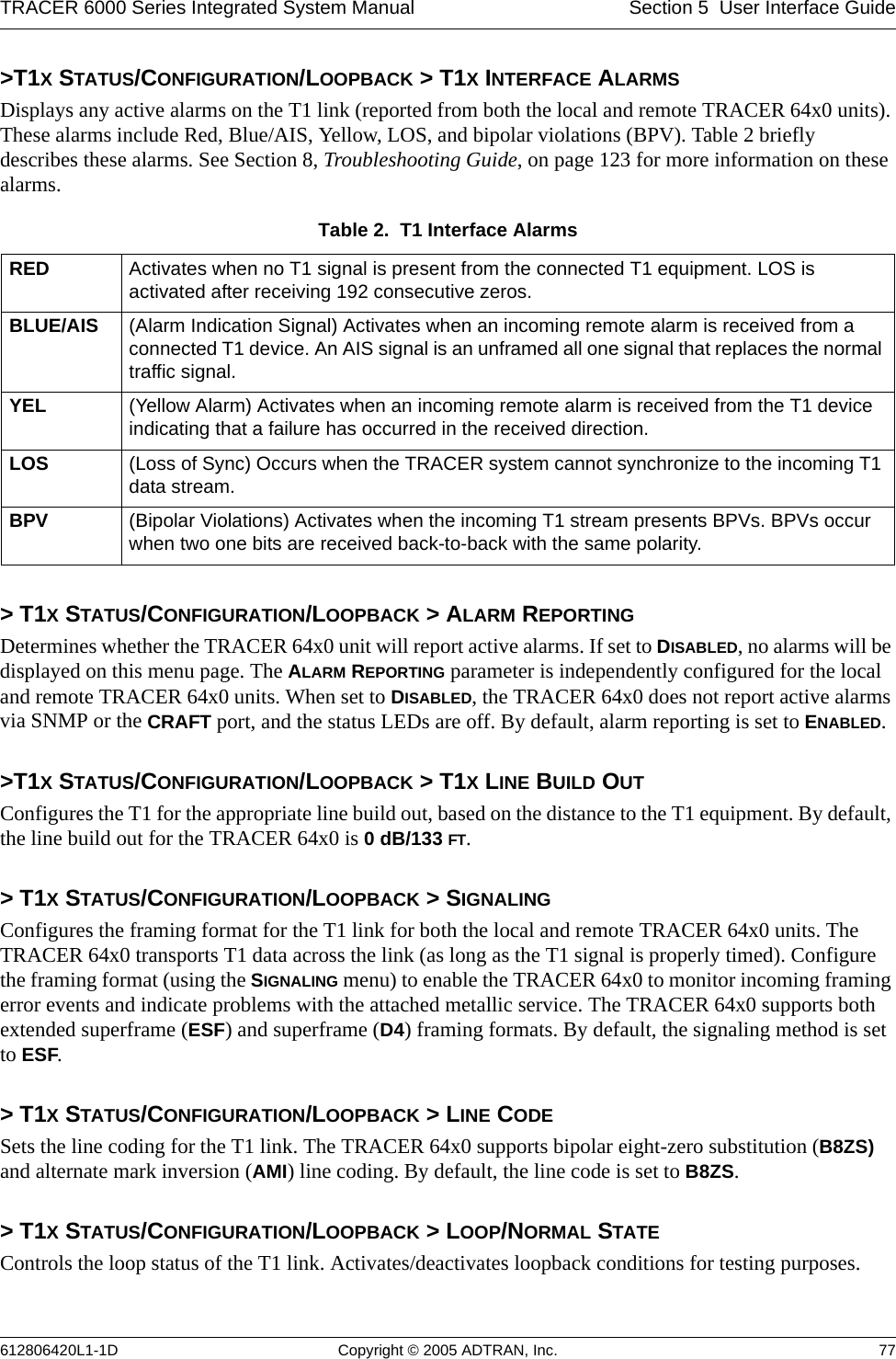
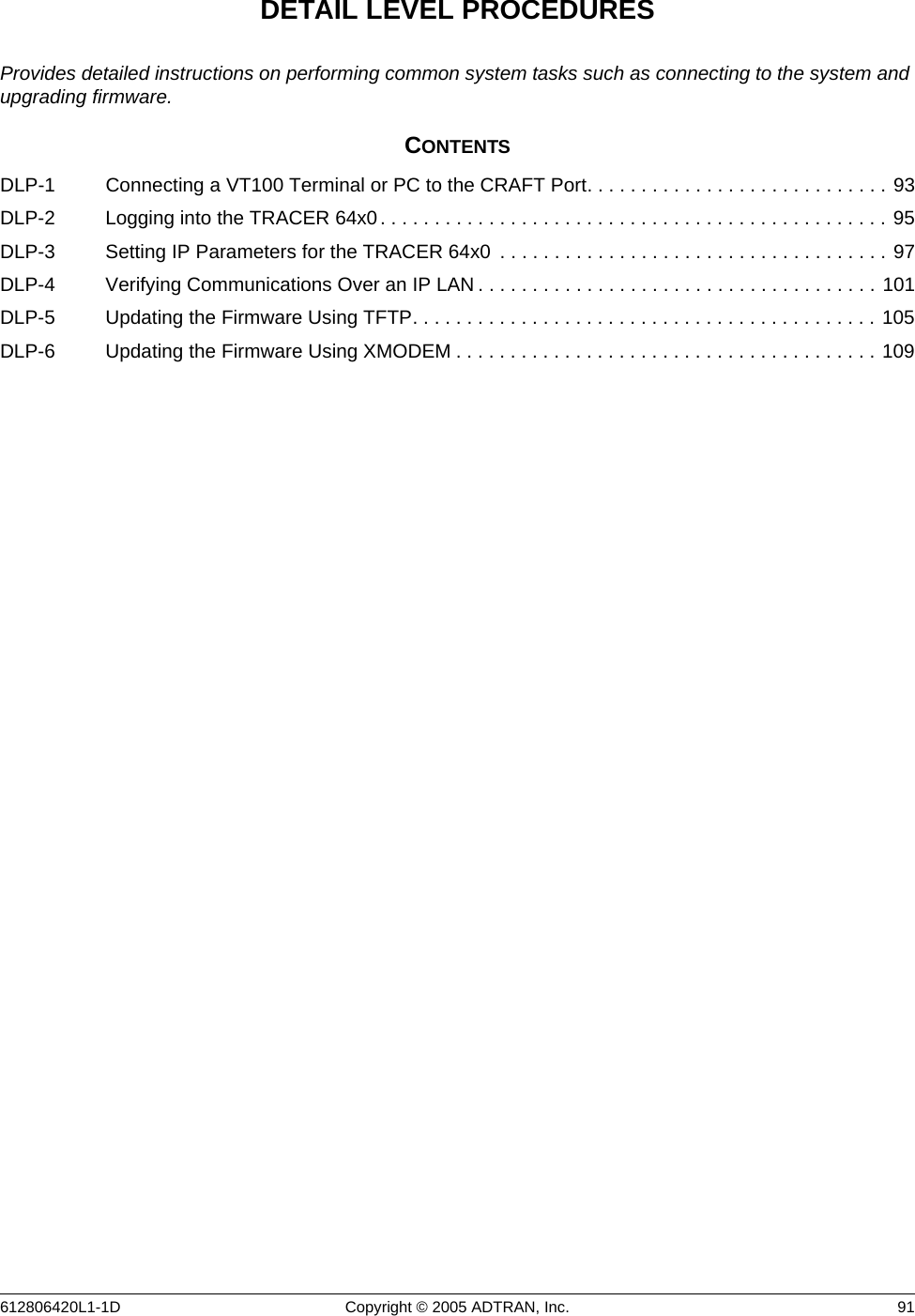
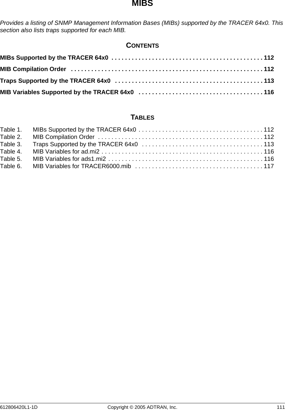
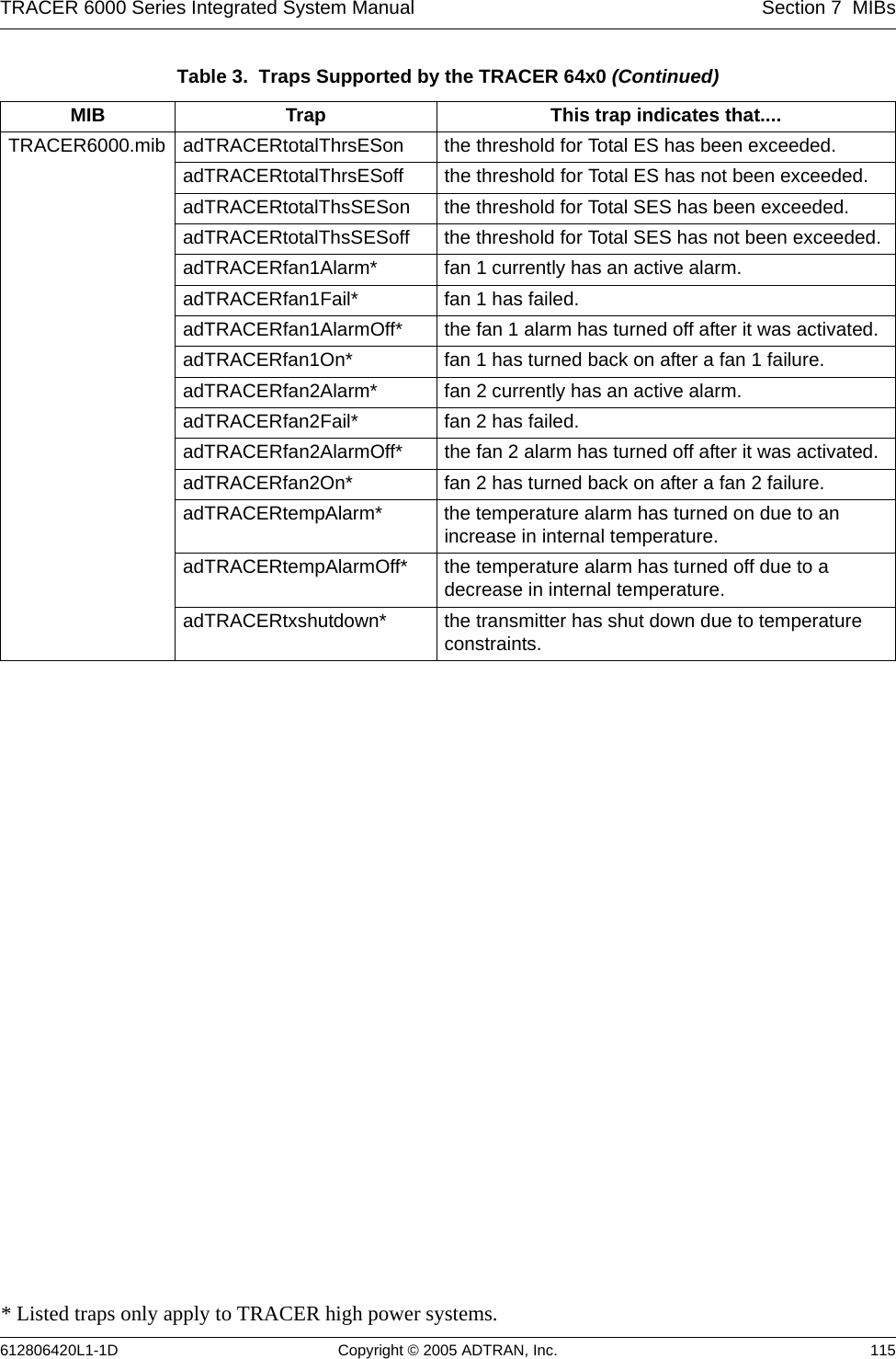
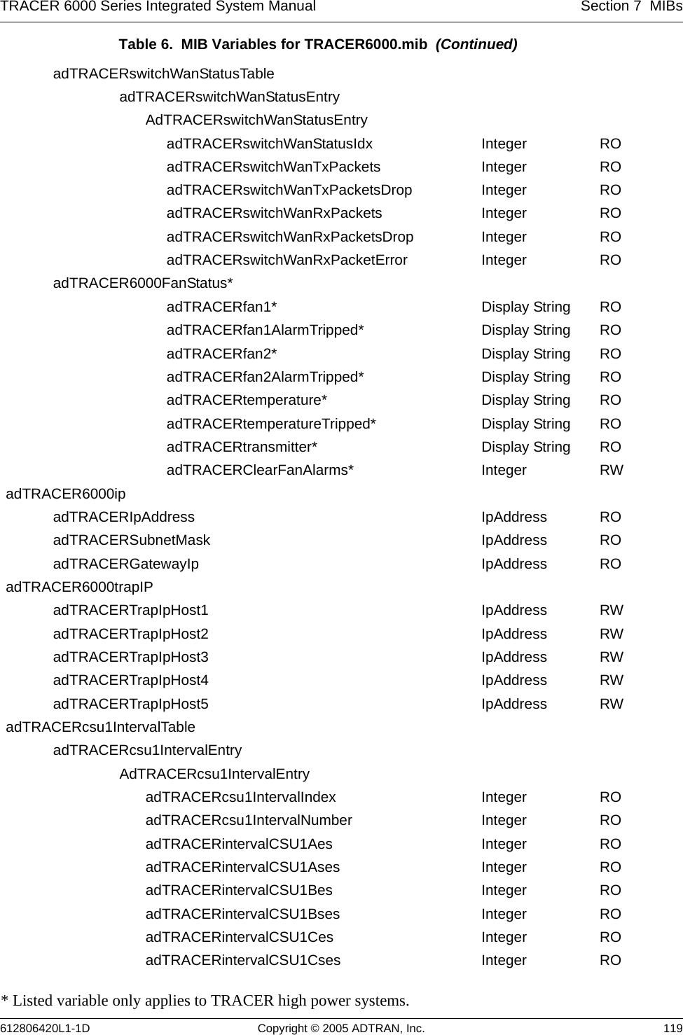
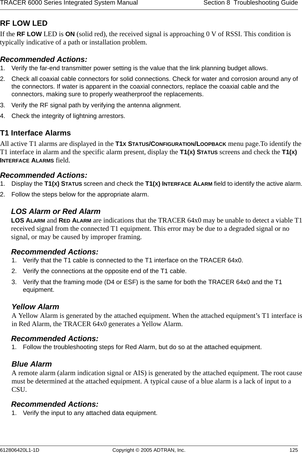
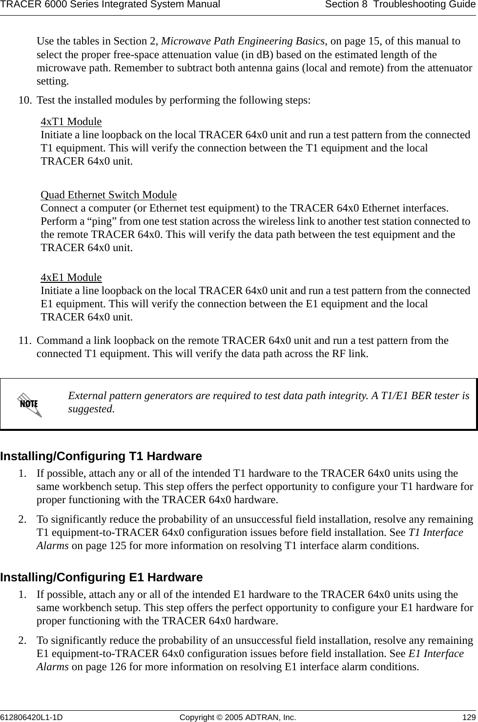
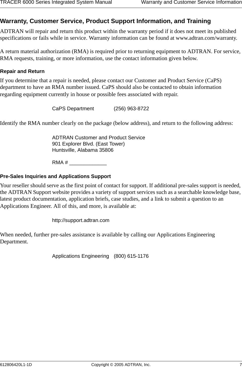
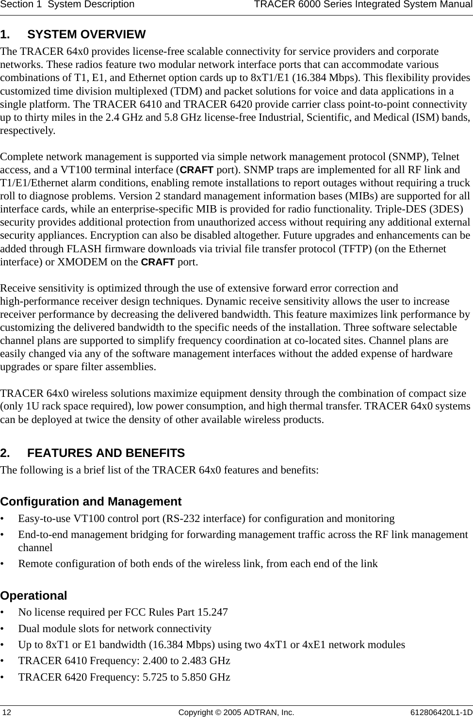
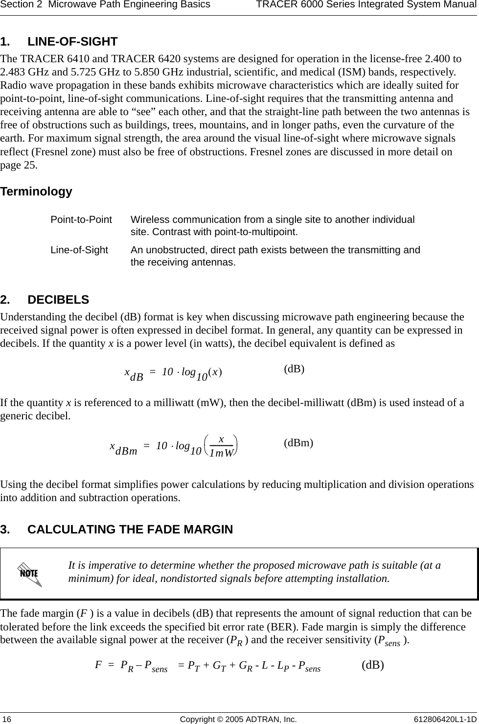
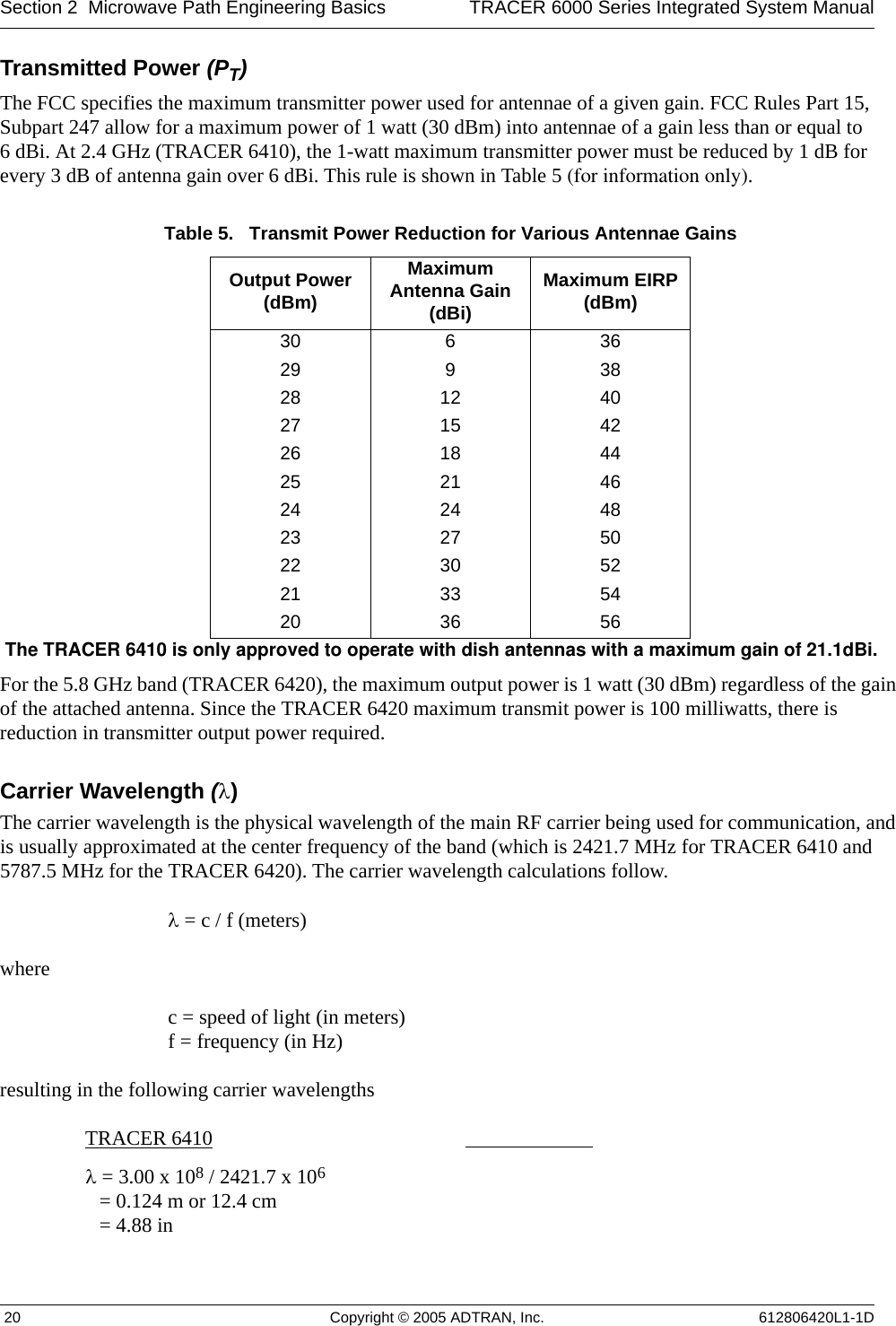
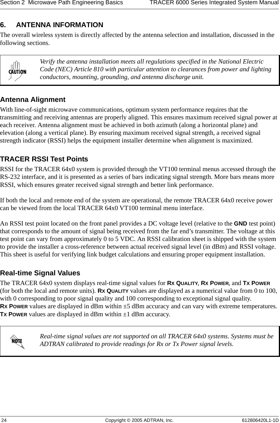
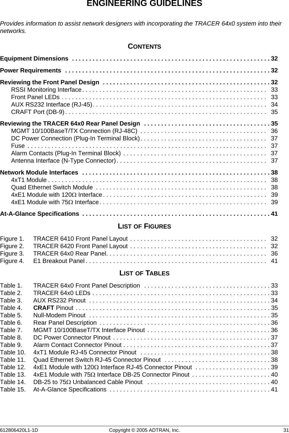
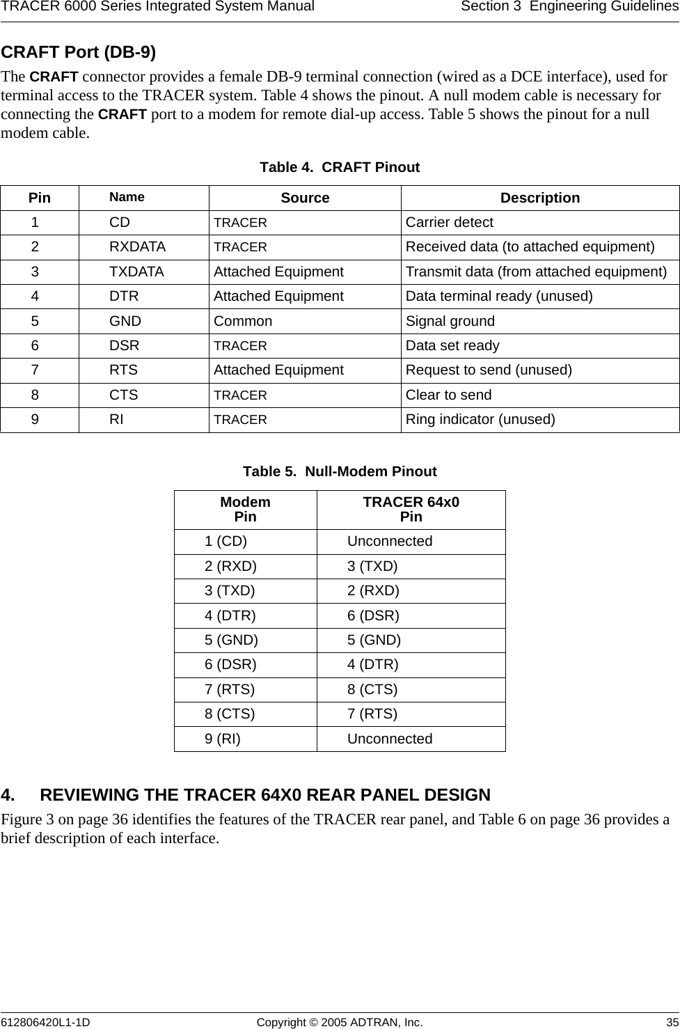
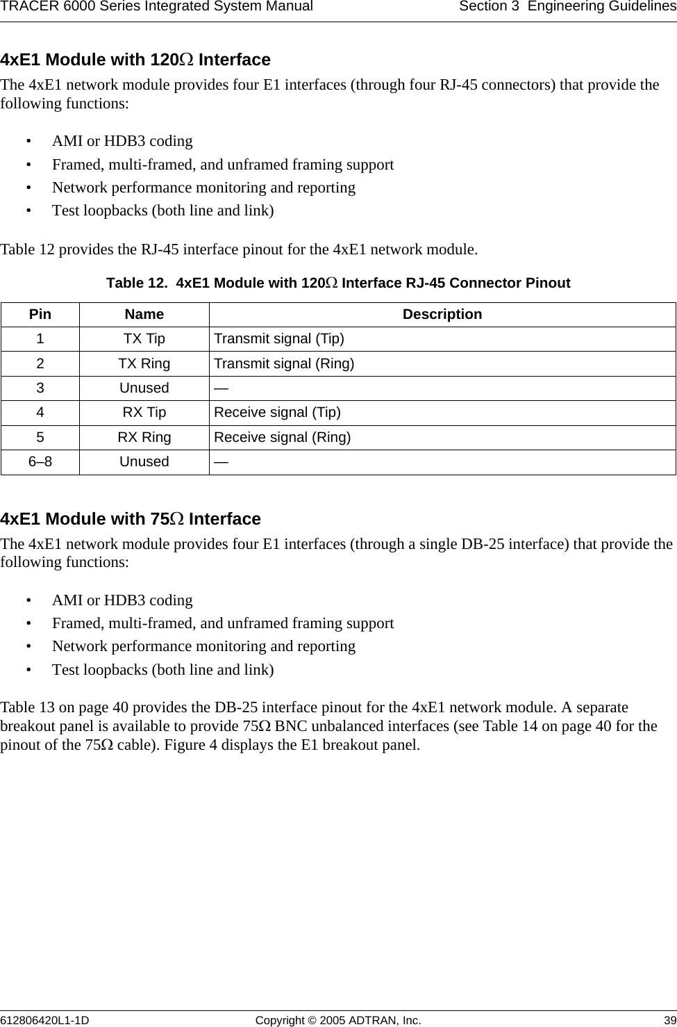
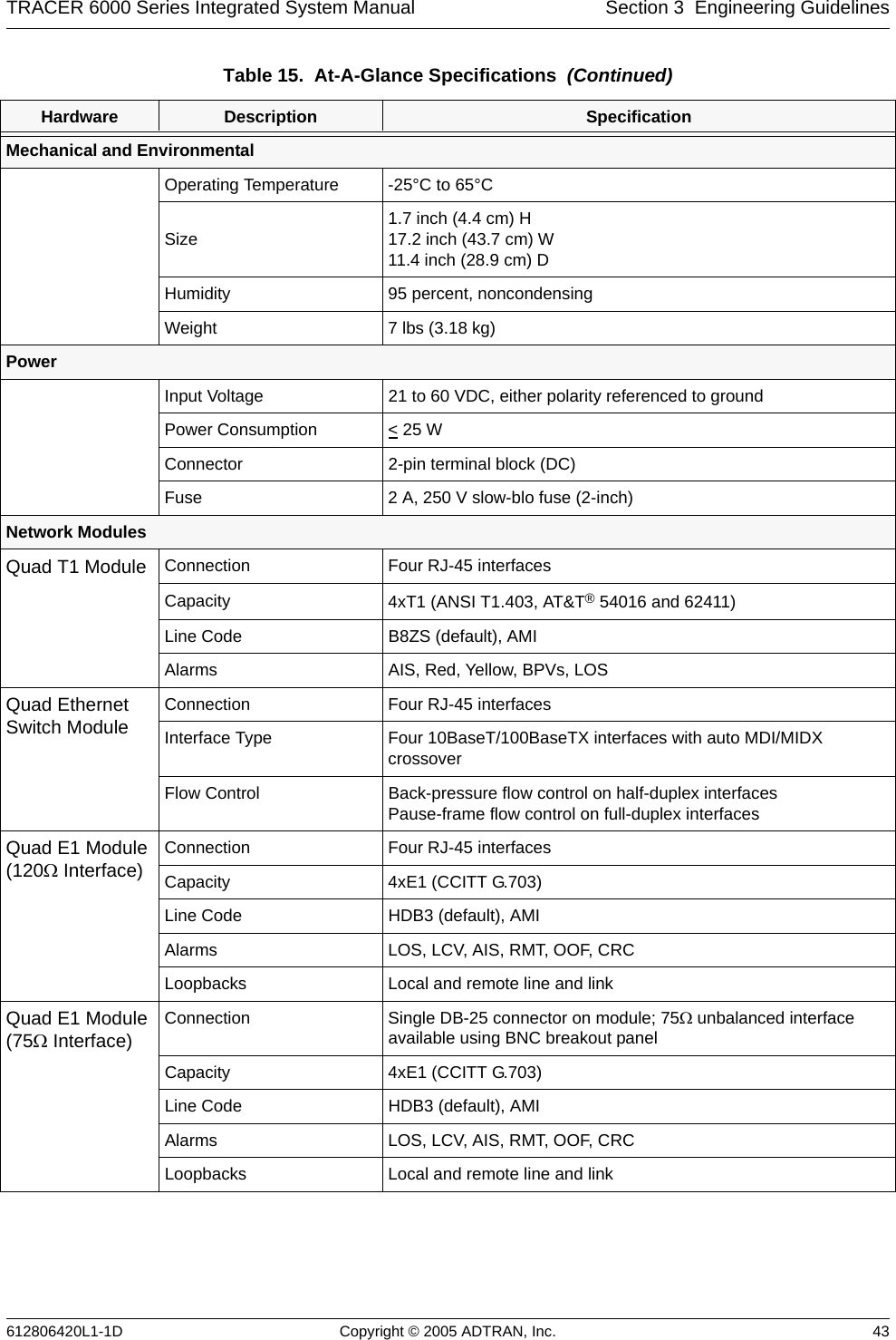
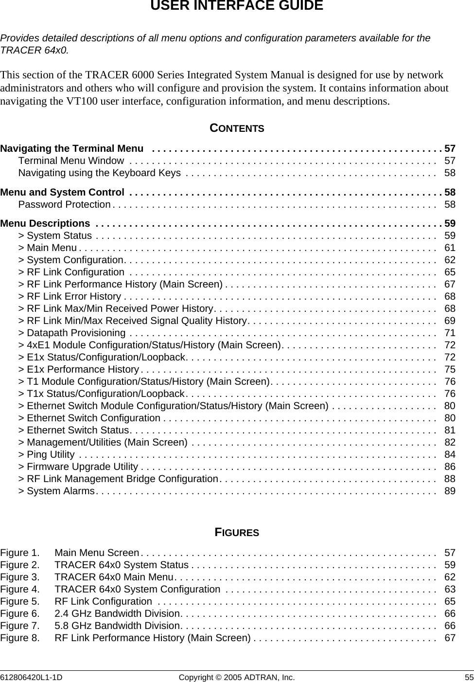
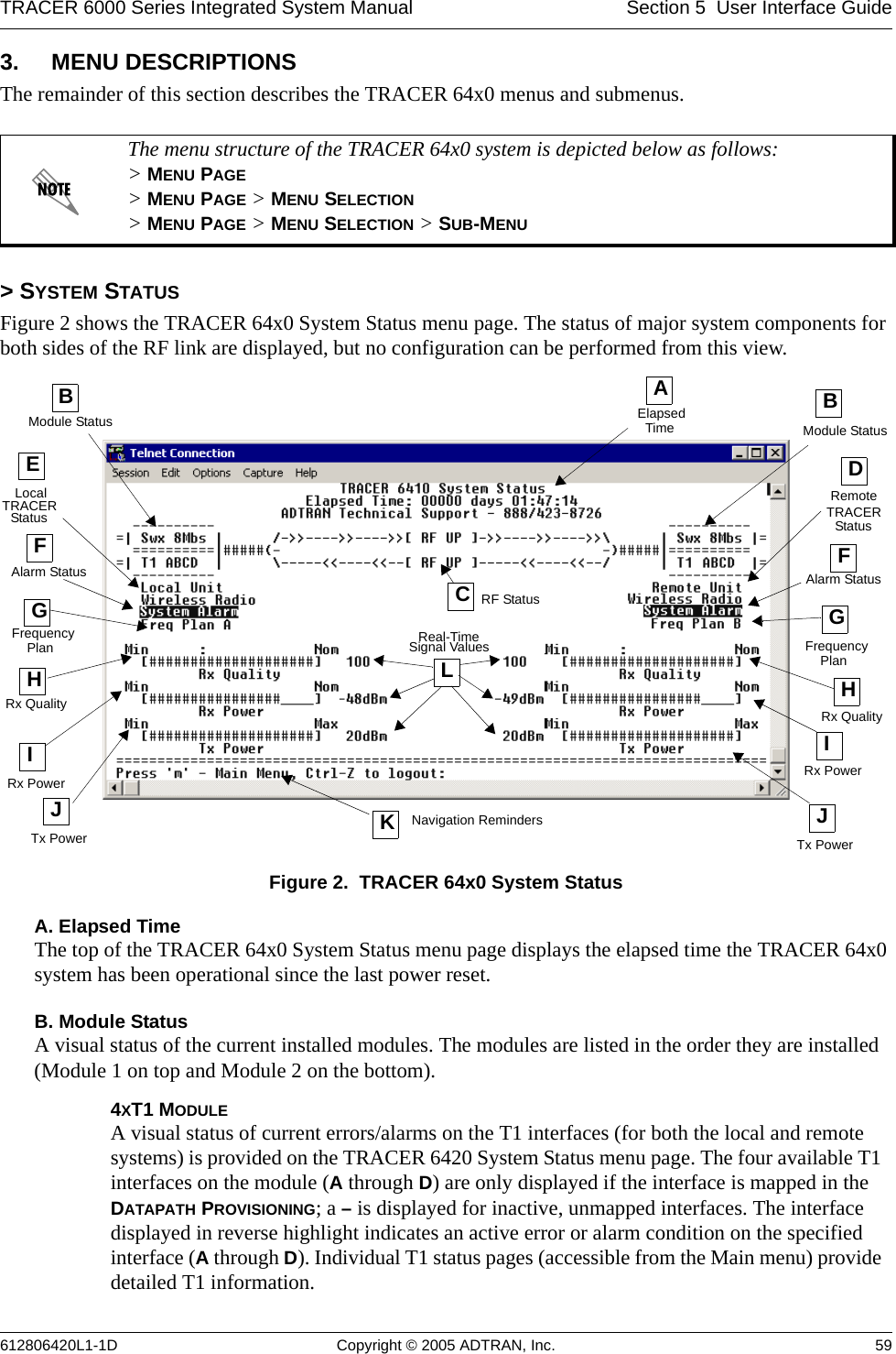
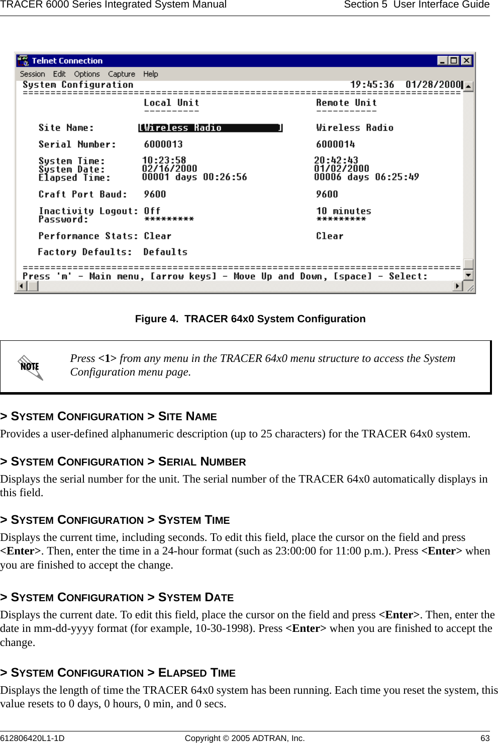
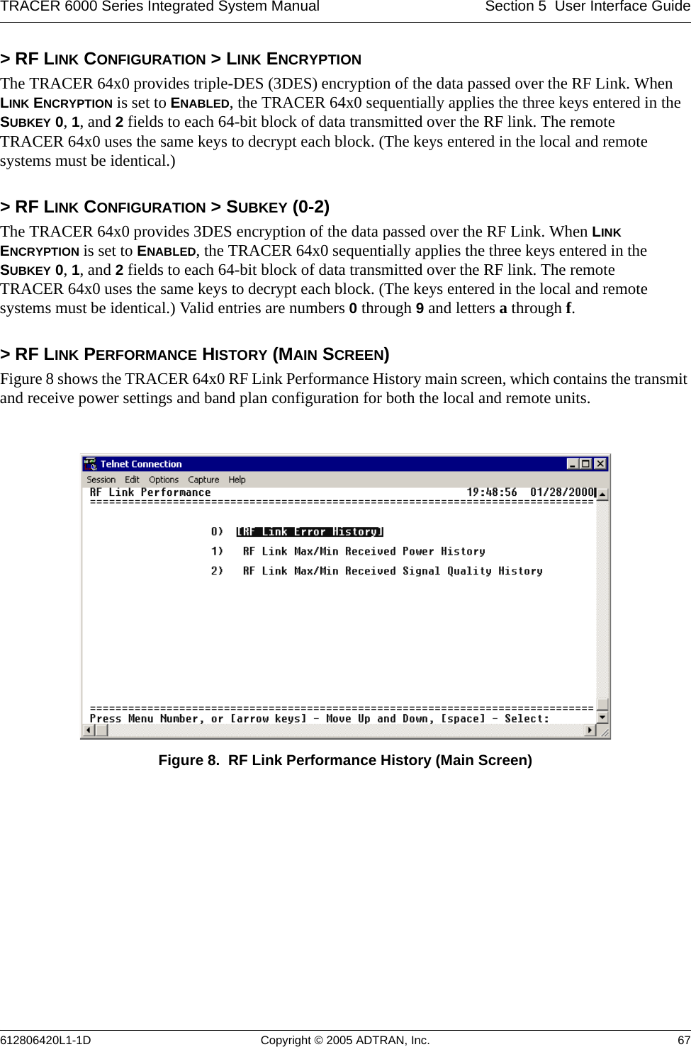
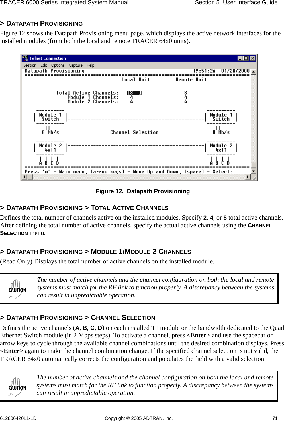
![Section 5 User Interface Guide TRACER 6000 Series Integrated System Manual 78 Copyright © 2005 ADTRAN, Inc. 612806420L1-1D> T1X STATUS/CONFIGURATION/LOOPBACK > LOOP/NORMAL STATE > NORMALDefines the T1 link as normal data transport mode; there are no active loopbacks.> T1X STATUS/CONFIGURATION/LOOPBACK > LOOP/NORMAL STATE > LINK [LOCAL]Activates a loopback at the local TRACER 64x0 T1 framer towards the remote end of the wireless link (see Figure 22). Use the local LINK loopback to loop the data transmitted from the remote end of the link back across the radio link to the remote end of the link. This loopback tests the integrity of the radio link and all the associated digital and RF hardware.Figure 22. T1 Local Link Loopback> T1X STATUS/CONFIGURATION/LOOPBACK > LOOP/NORMAL STATE > LINK [REMOTE]Activates a loopback at the remote TRACER 64x0 T1 framer towards the local end of the wireless link (see Figure 23). Use the remote LINK loopback to loop the data transmitted from the local end of the link across the radio link to the local end of the link. This loopback tests the integrity of the radio link and all the associated digital and RF hardware.Figure 23. T1 Remote Link Loopback> T1X STATUS/CONFIGURATION/LOOPBACK > LOOP/NORMAL STATE > LINE [LOCAL]Activates a loopback at the local TRACER 64x0 T1 framer towards the connected T1 equipment (see Figure 24). Use the local LINE loopback to test data path integrity from the local TRACER 64x0 unit to the connected T1 equipment.Figure 24. T1 Local Line Loopback> T1X STATUS/CONFIGURATION/LOOPBACK > LOOP/NORMAL STATE > LINE [REMOTE]Activates a loopback at the remote TRACER 64x0 T1 framer towards the connected T1 equipment at the remote end of the link (see Figure 25). Use the remote LINE loopback to test data path integrity from the remote TRACER 64x0 unit to the T1 equipment connected at the remote end of the link.Figure 25. T1 Remote Line Loopback](https://usermanual.wiki/ADTRAN/TRC6410L2X/User-Guide-696397-Page-76.png)