AGD SYSTEMS AGD315-207 AGD 315-207-000 Microwave Vehicle Detector User Manual AGD340
AGD SYSTEMS LTD AGD 315-207-000 Microwave Vehicle Detector AGD340
UserManual.wiki
>
AGD SYSTEMS
>
AGD315 207 User Manual
manual
Navigation menu
Upload a User Manual
Namespaces
Wiki Guide
HTML
PDF
Info
Views
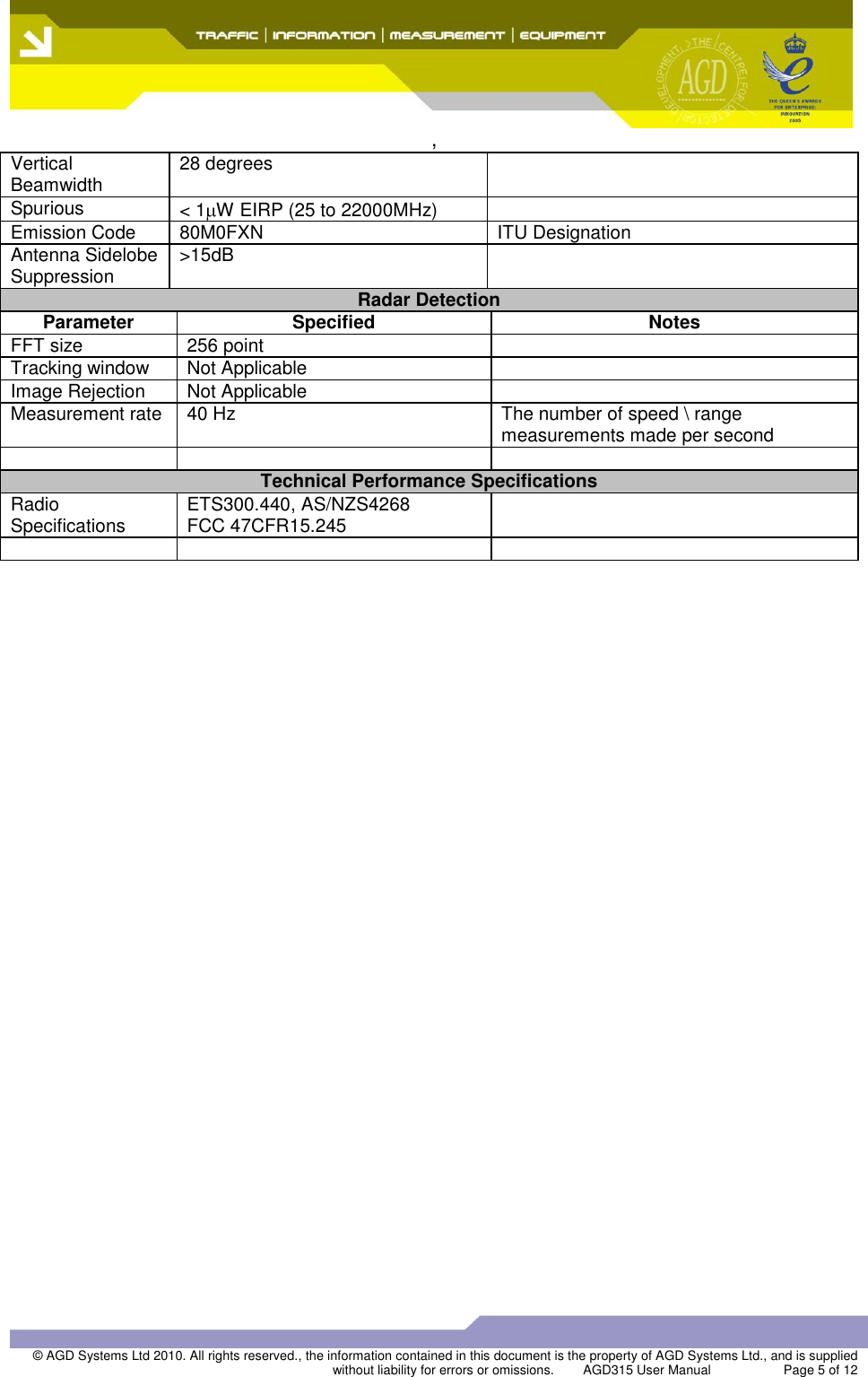
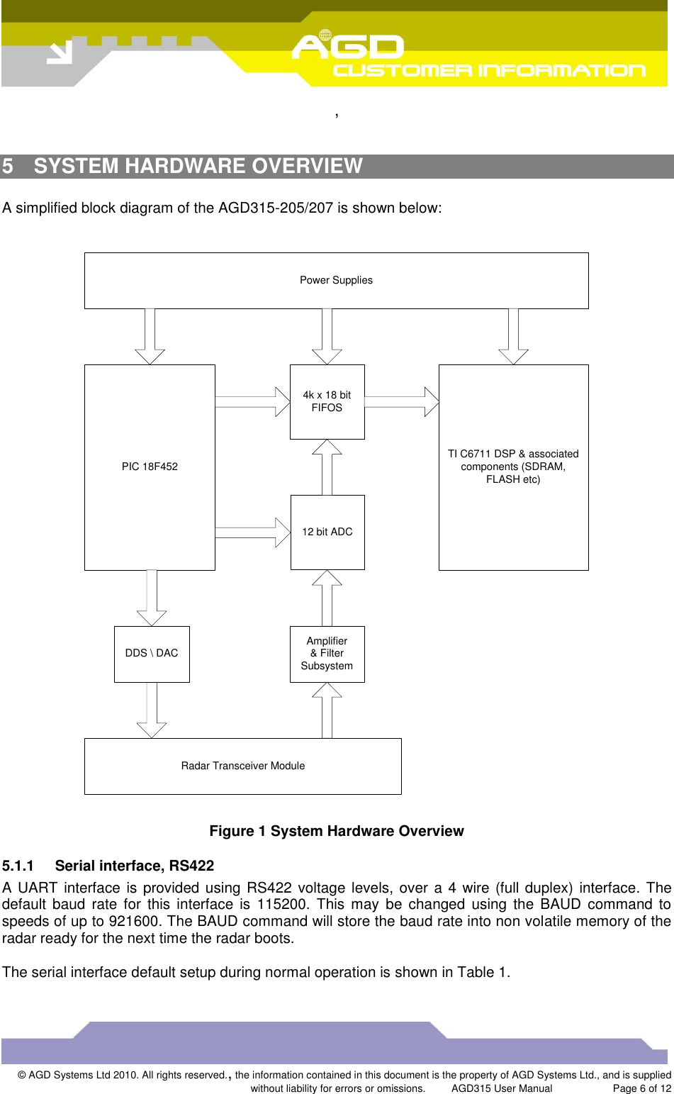
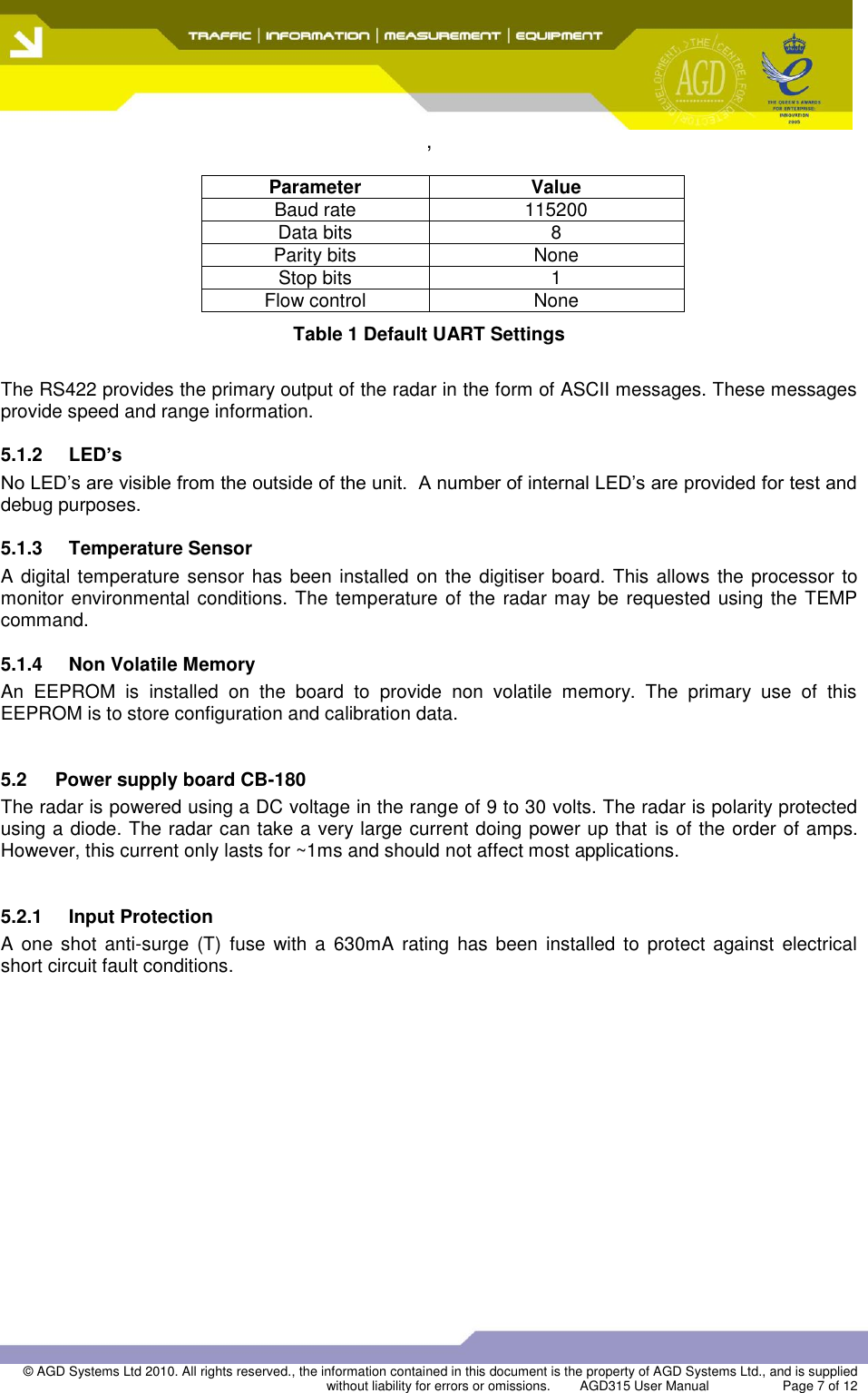
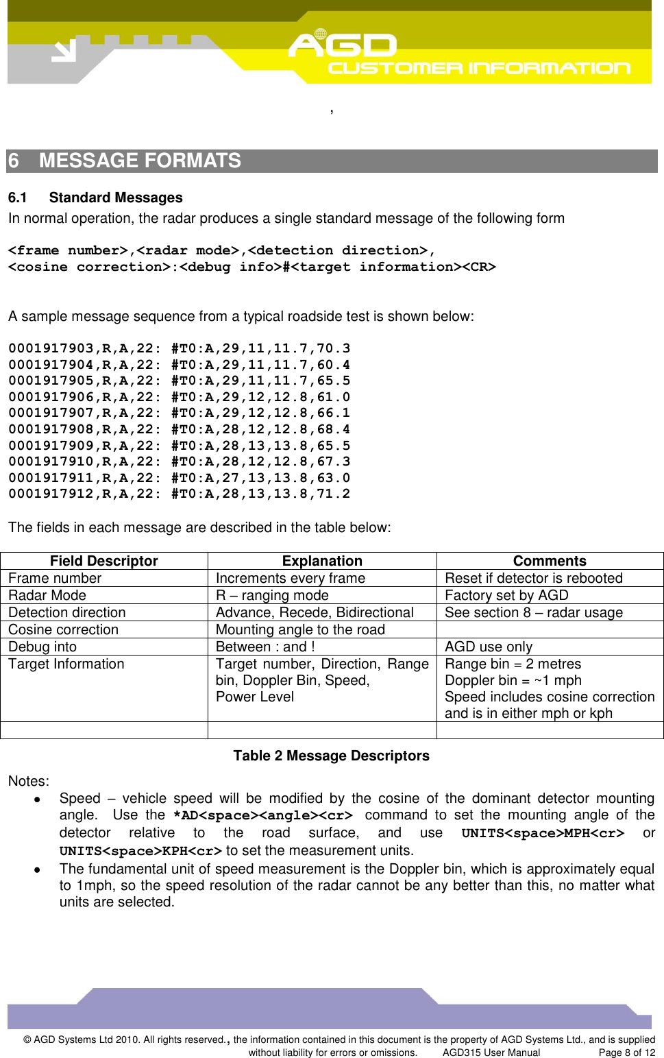
User Manual
Discussion / Help
Navigation