AGD SYSTEMS AGD315-207 AGD 315-207-000 Microwave Vehicle Detector User Manual AGD340
AGD SYSTEMS LTD AGD 315-207-000 Microwave Vehicle Detector AGD340
manual
© AGD Systems Ltd 2010. All rights reserved., the information contained in this document is the property of AGD Systems Ltd., and is supplied
without liability for errors or omissions. AGD315 User ManualPage 1 of 12
AGD315-205 and AGD315-207
RADAR USERS MANUAL
1 INTRODUCTION
These instructions detail the use and operation
of the AGD315-205 and -207 radars. This
radar has been specifically designed for the
accurate measurement of the speed and range
of passing vehicles when mounted at the side
of the road for enforcement purposes. The
radar is designed to work in conjunction with
an AGD340 radar plus a host, photographic
based, enforcement system. The host system
may be mobile or fixed location in nature.
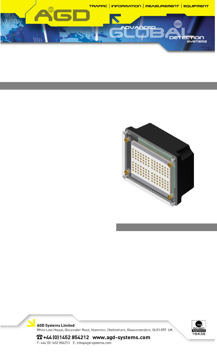
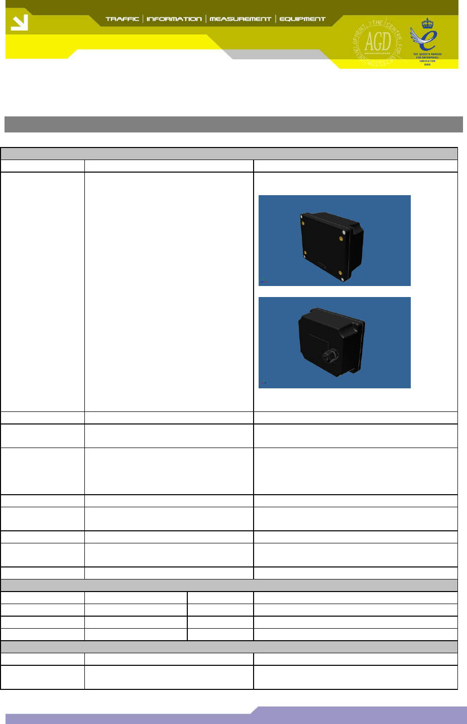
The radar is supplied in a black plastic
enclosure which incorporates all the radar
circuitry and processing circuitry to perform the
speed and range measurement. The
connection to the radar is via a 1 metre cable
with multi-pin connector, and mounting is
provided by fixings on the housing.
The AGD315-205 is a 24.2GHz frequency
modulated continuous wave (FMCW) radar
whereas the AGD315-207 is a 24.125GHz
(24.075GHz-24.175GHz) radar which are
capable of measuring range and speed. The
radar’s integral planar antenna forms a narrow
beam which is sited at a predetermined angle
across the road. When vehicles pass through
the beam the radar accurately measures the
speed and range at a frame rate of 40
readings per second via an advanced digitising
and tracking technique to a resolution of
approximately 1 mph and 2 metres.
Details of each vehicle speed measurement
are passed to the host system via a high
speed serial communications interface.
Changes or modifications to this equipment,
not expressly approved by AGD Systems Ltd,
may void the user’s authority to operate this
equipment
Contents
1 INTRODUCTION
2 DOCUMENT REVISION
3 FMCW OVERVIEW
4 SPECIFICATIONS
5 SYSTEM HARDWARE OVERVIEW
6 MESSAGE FORMATS
7 RADAR USAGE
8 CABLE CONNECTIONS
9 TEST & CALIBRATION

,
© AGD Systems Ltd 2010. All rights reserved., the information contained in this document is the property of AGD Systems Ltd., and is supplied
without liability for errors or omissions. AGD315 User Manual Page 2 of 12
2 DOCUMENT REVISION
Issue
Amendment Details
Date of Issue
By
1
Initial Draft
23/12/2009
NK
2
DCR3006 – added section relating to test and
calibration procedures. Figures and Tables
identified using auto-numbered captions.
14/06/2010
SCH
3 FMCW OVERVIEW
3.1 Basic Operating Principles of FMCW Radar
In an FMCW radar such as the AGD315-205/207, the following basic operating principles are applied:
The transmit signal is frequency modulated, normally by a linear modulation (a chirp)
The modulation of the received signal is compared to the modulation of the transmitted signal to
determine time delay and therefore range
velocity is determined by range differentiation or Doppler processing
Consider a signal transmitted from the radar at time t=0 and with frequency fstart. When this signal
strikes a target, the signal will be reflected back and received by the radar at a time t=tdelayed. During
the time of flight of the reflected signal. the transmit frequency will have increased to a new frequency
fdelayed, where fdelayed is given by the chirp rate and amplitude.
Hence at any instance in time after tdelayed, there is a difference in frequency between the transmitted
and received frequencies. This frequency difference is proportional to the time of flight for the
received signal, and since the radar signal travels at the speed of light (a constant), the time of flight is
also proportional to the range of the target which reflected the radar signal.
In an FMCW system, the transmit and receive signals are compared using an RF Mixer. The mixer is
driven by the transmit and receive signals, and the mixer output is the difference between the two
input signals. The output signal is referred to as the intermediate frequency (IF).
If the IF is sampled into an analogue to digital converter (ADC) at fixed time intervals during a single
excursion of the frequency modulation (one period of the chirp) and the resultant digital signal is
viewed in the frequency domain, a number of different frequencies will be seen, where each frequency
corresponds to a target at a particular range.
If data from a number of successive chirps is gathered and processed, speed and range for individual
targets can be determined.
,
© AGD Systems Ltd 2010. All rights reserved., the information contained in this document is the property of AGD Systems Ltd., and is supplied
without liability for errors or omissions. AGD315 User Manual Page 3 of 12
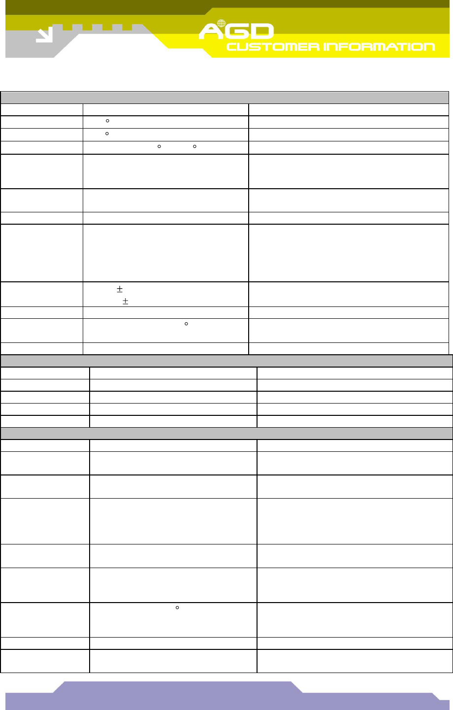
4 SPECIFICATIONS
Radar General
Items
Specification
Notes
Housing
Black UV stabilised polycarbonate
Fine spark finish
Radar Weight
0.80 Kg
Including 1 metre lead and connector
External
Dimensions
160mm(W) x 130mm(H) x
60mm(D)
Mounting
Fixings
4 x M4 threaded inserts
M16 cable gland
Sealing
IP66
Radar
Connection
9 pin Bulgin Bucanneer (male)
attached to end of 1 metre lead
Bulgin PX0728/P
See section 9 for more information
Radar Labelling
Manufacturer’s Label
LED
Red status indicator LED
Blue ‘Bluetooth’ indicator LED
Radar Power Connection
Parameter
Specified
Tolerance
Notes
Supply Voltage
24V dc
9-30V
Current
263mA
10%
At 12Vdc
Radar Data Connection
Parameter
Specified
Notes
4 wire RS 422
See extra notes on data connection and
BAUD command.
,
© AGD Systems Ltd 2010. All rights reserved., the information contained in this document is the property of AGD Systems Ltd., and is supplied
without liability for errors or omissions. AGD315 User Manual Page 4 of 12
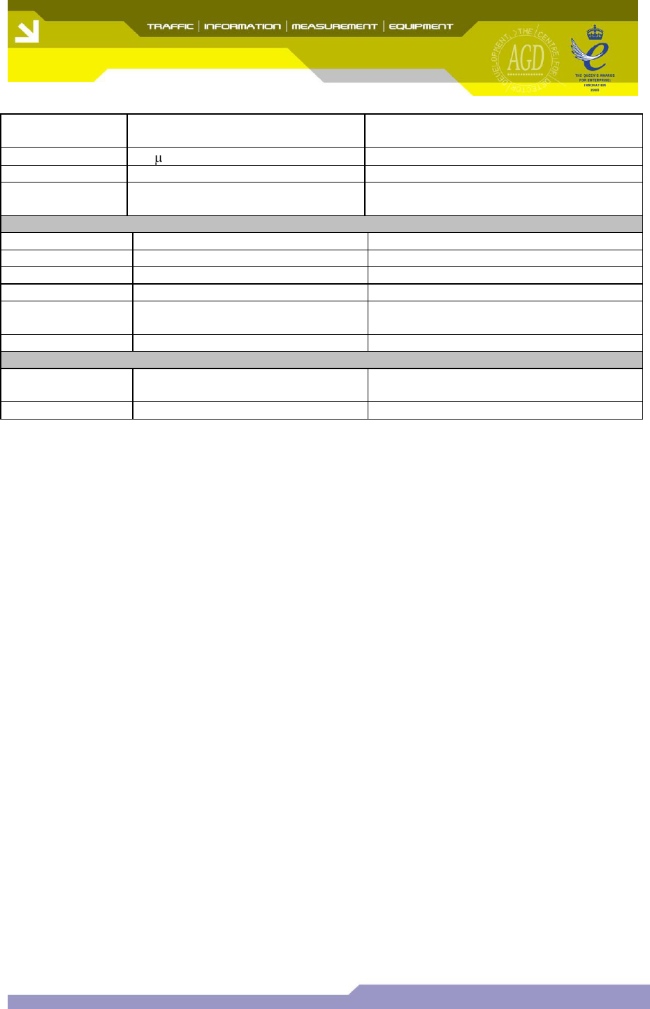
Environmental Performance
Test
Severity
Specification
Cold
(-20 C Operational)
IEC 68-2-1 Test Ab
Dry Heat
+60 C Operational
IEC 68-2-2 Test Bb
Damp Heat
Cyclic 48Hrs 25 C to 40 C 95%RH
IEC 68-2-30 Test Db
Free Fall
Each top rear corner & each top
rear face. 1000mm free fall to
concrete.
IEC 68-2-32 Test Ed
Drop and
Topple
All faces & corners 100mm drop
IEC 68-2-31 Test Ec
Shock
4000m/S2, 2mS Duration
IEC 68-2-27 Test Ea
Random
Vibration
0.02g2/ Hz (10-50Hz)
0.01g2/ Hz (50-150Hz)
0.002g2/ Hz (150-500Hz)
Overall RMS 1.58g 3Hrs on X,Y,Z
axes
IEC 68-2-34 Test Fd
Sinusoidal
Vibration
5-7Hz 1.5mm
7-35Hz 10m/S2
IEC 68-2-6 Test Fc
Bump
1000 in X,Y,Z axes 100m/S2,16mS
IEC 68-2-29 TestEb
Immersion
Preconditioned to +30 C over
ambient before 12Hrs Immersion.
IEC 68-2-18 Test R
Radar Transceiver
Component
Specification
Notes
Antenna
Planar patch array
Transmitter
Quarter wave resonator
Receiver
Homodyne I Q down converter
Radome
Black UV stabilised polycarbonate
Radar Transmission
Parameter
Specified
Notes
Radar Centre
Frequency
24.200 GHz UK/EU/AS/NZS
24.125GHz USA
Modulation
Bandwidth
80MHz
Operating
Frequency Band
24.150 - 24.250GHz (UK/EU/AS/NZS)
24.075 – 24.175GHz (USAVersion)
Modulation bandwidth of ~80MHz plus
temperature stability guard bands (+/-
10MHz)
Fundamental
Frequency Power
<20dBm EIRP
Fundamental
Frequency Field
Strength
<1000mV/m
@3m
Frequency
Temperature
Stability
Typically < 1 MHz/ C
Uncompensated
Polarisation
Plane polarised with E-Field vertical
Horizontal
Beamwidth
7 degrees
,
© AGD Systems Ltd 2010. All rights reserved., the information contained in this document is the property of AGD Systems Ltd., and is supplied
without liability for errors or omissions. AGD315 User Manual Page 5 of 12
Vertical
Beamwidth
28 degrees
Spurious
< 1 W EIRP (25 to 22000MHz)
Emission Code
80M0FXN
ITU Designation
Antenna Sidelobe
Suppression
>15dB
Radar Detection
Parameter
Specified
Notes
FFT size
256 point
Tracking window
Not Applicable
Image Rejection
Not Applicable
Measurement rate
40 Hz
The number of speed \ range
measurements made per second
Technical Performance Specifications
Radio
Specifications
ETS300.440, AS/NZS4268
FCC 47CFR15.245
,
© AGD Systems Ltd 2010. All rights reserved., the information contained in this document is the property of AGD Systems Ltd., and is supplied
without liability for errors or omissions. AGD315 User Manual Page 6 of 12
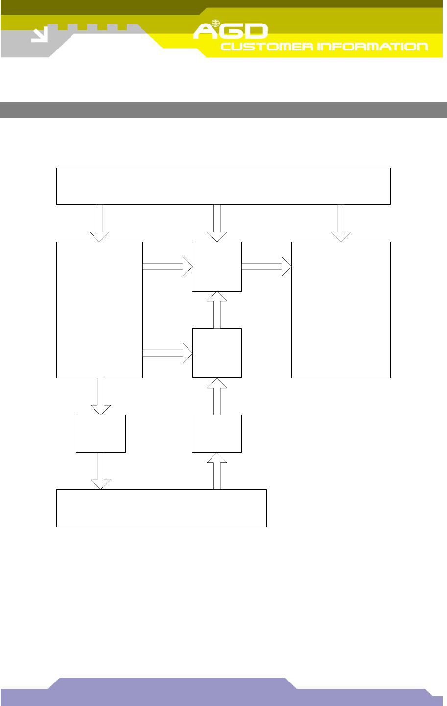
5 SYSTEM HARDWARE OVERVIEW
A simplified block diagram of the AGD315-205/207 is shown below:
4k x 18 bit
FIFOS
12 bit ADC
Radar Transceiver Module
DDS \ DAC Amplifier
& Filter
Subsystem
PIC 18F452 TI C6711 DSP & associated
components (SDRAM,
FLASH etc)
Power Supplies
Figure 1 System Hardware Overview
5.1.1 Serial interface, RS422
A UART interface is provided using RS422 voltage levels, over a 4 wire (full duplex) interface. The
default baud rate for this interface is 115200. This may be changed using the BAUD command to
speeds of up to 921600. The BAUD command will store the baud rate into non volatile memory of the
radar ready for the next time the radar boots.
The serial interface default setup during normal operation is shown in Table 1.

,
© AGD Systems Ltd 2010. All rights reserved., the information contained in this document is the property of AGD Systems Ltd., and is supplied
without liability for errors or omissions. AGD315 User Manual Page 7 of 12
Parameter
Value
Baud rate
115200
Data bits
8
Parity bits
None
Stop bits
1
Flow control
None
Table 1 Default UART Settings
The RS422 provides the primary output of the radar in the form of ASCII messages. These messages
provide speed and range information.
5.1.2 LED’s
No LED’s are visible from the outside of the unit. A number of internal LED’s are provided for test and
debug purposes.
5.1.3 Temperature Sensor
A digital temperature sensor has been installed on the digitiser board. This allows the processor to
monitor environmental conditions. The temperature of the radar may be requested using the TEMP
command.
5.1.4 Non Volatile Memory
An EEPROM is installed on the board to provide non volatile memory. The primary use of this
EEPROM is to store configuration and calibration data.
5.2 Power supply board CB-180
The radar is powered using a DC voltage in the range of 9 to 30 volts. The radar is polarity protected
using a diode. The radar can take a very large current doing power up that is of the order of amps.
However, this current only lasts for ~1ms and should not affect most applications.
5.2.1 Input Protection
A one shot anti-surge (T) fuse with a 630mA rating has been installed to protect against electrical
short circuit fault conditions.
,
© AGD Systems Ltd 2010. All rights reserved., the information contained in this document is the property of AGD Systems Ltd., and is supplied
without liability for errors or omissions. AGD315 User Manual Page 8 of 12
6 MESSAGE FORMATS
6.1 Standard Messages
In normal operation, the radar produces a single standard message of the following form
<frame number>,<radar mode>,<detection direction>,
<cosine correction>:<debug info>#<target information><CR>
A sample message sequence from a typical roadside test is shown below:
0001917903,R,A,22: #T0:A,29,11,11.7,70.3
0001917904,R,A,22: #T0:A,29,11,11.7,60.4
0001917905,R,A,22: #T0:A,29,11,11.7,65.5
0001917906,R,A,22: #T0:A,29,12,12.8,61.0
0001917907,R,A,22: #T0:A,29,12,12.8,66.1
0001917908,R,A,22: #T0:A,28,12,12.8,68.4
0001917909,R,A,22: #T0:A,28,13,13.8,65.5
0001917910,R,A,22: #T0:A,28,12,12.8,67.3
0001917911,R,A,22: #T0:A,27,13,13.8,63.0
0001917912,R,A,22: #T0:A,28,13,13.8,71.2
The fields in each message are described in the table below:
Field Descriptor
Explanation
Comments
Frame number
Increments every frame
Reset if detector is rebooted
Radar Mode
R – ranging mode
Factory set by AGD
Detection direction
Advance, Recede, Bidirectional
See section 8 – radar usage
Cosine correction
Mounting angle to the road
Debug into
Between : and !
AGD use only
Target Information
Target number, Direction, Range
bin, Doppler Bin, Speed,
Power Level
Range bin = 2 metres
Doppler bin = ~1 mph
Speed includes cosine correction
and is in either mph or kph
Table 2 Message Descriptors
Notes:
Speed – vehicle speed will be modified by the cosine of the dominant detector mounting
angle. Use the *AD<space><angle><cr> command to set the mounting angle of the
detector relative to the road surface, and use UNITS<space>MPH<cr> or
UNITS<space>KPH<cr> to set the measurement units.
The fundamental unit of speed measurement is the Doppler bin, which is approximately equal
to 1mph, so the speed resolution of the radar cannot be any better than this, no matter what
units are selected.
,
© AGD Systems Ltd 2010. All rights reserved., the information contained in this document is the property of AGD Systems Ltd., and is supplied
without liability for errors or omissions. AGD315 User Manual Page 9 of 12
7 RADAR USAGE
7.1 Introduction
For best detection performance the radar must be setup correctly. Failure to do so can result in
inaccurate or false detections.
7.2 System Integration
The AGD315-205/207 has been designed to be used in conjunction with the AGD340 and a host
system. It is the responsibility of the supplier of the host system to ensure that data fusion \ correlation
of the speed and range data from the AGD315-205/207 and speed data from the AGD340 is done in
such a manner as to be ‘fit for purpose’.
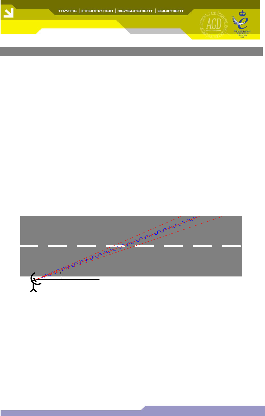
7.3 Radar Mounting Angle
Radars are supplied factory programmed to be used for a specific mounting angle, usually to 22
degrees. This angle is the angle the radar points across the road from the direction of the road, see
Error! Reference source not found.. The angle is also reported in all output messages and the
command *AD may be used to determine it. This angle is used by the radar to adjust the speed the
radar measures to the actual target speed and therefore it is important the radar is setup with the
correct angle. If the radar is setup with an angle that is less than the mounting angle then the radar will
measure speeds that are larger than the vehicles true speed, while if the angle is greater than the
mounting angle the radar will measure speeds that are less than the vehicles true speed.
22o
Figure 2 Radar Mounting Angle
The radar transmits a radio beam across the road that has a horizontal beam width of ~7 degrees. The
vertical beam width of the radar beam is relatively large at 28degrees so although the radar should be
made level this is not crucial for correct operation. For a fixed camera installation often the radar is
mounted relatively high (~3m) and in this case it is desirable to point the radar more down towards the
ground. In this application careful consideration of the radar beam and its shape is required to ensure
that all the lanes of the road are covered.
,
© AGD Systems Ltd 2010. All rights reserved., the information contained in this document is the property of AGD Systems Ltd., and is supplied
without liability for errors or omissions. AGD315 User Manual Page 10 of 12
7.4 Maximum Speed Measurement
Normally, the radar can detect targets travelling in both directions simultaneously (if required) at
speeds of up to 128mph. The radar can resolve the speed to the nearest Doppler bin, which is
approximately equal to 1mph.
In some situations, it may be required that the radar measure higher target speeds than 128mph. It is
possible to configure the radar to measure targets up to 255mph, but with the caveat that the radar
must be set into either advance or recede mode (not bidirectional), and targets travelling in the wrong
direction at sufficient speed will generate erroneous speed readings which appear to have come from
the required direction.
For example, if the radar is set into advance mode, and the command *RV<space>150<cr> is sent
to the radar, the following behaviour will be seen:
Vehicle
Speed (mph)
Vehicle
Direction
Radar Operation
0 – 10
Approach
Vehicle not detected, speed is below the low speed cutoff
10 – 150
Approach
Vehicle detected, speed and direction measured correctly, message sent
150+
Approach
Vehicle not detected, speed is above upper limit set by *RV
0 – 10
Recede
Vehicle not detected, speed is below the low speed cutoff
10-105
Recede
Vehicle detected, speed and direction measured correctly, no message
105+
Recede
Vehicle detected, speed and direction measured incorrectly, message sent
Table 3 Maximum Speed Behaviour
So, the *RV command is used to set the maximum speed measurable in the required direction. Under
most situations, the erroneous speed measured can be filtered out because the range measurement
will be incorrect.
One situation where the range cannot be used to filter out erroneous targets is for a vehicle driving the
wrong way down the road at excessive speed (for example, a vehicle driving the wrong way down a
dual carriageway or motorway). However, two radars deployed at the same position, one set to
approach and one set to recede, both with the same *RV setting could be used under these
circumstances, which would give the capability to measure up to ±255mph (255mmph approach with
one radar, 255mph recede with the other). Under most normal situations however, a single radar will
the capability for ±128mph should be sufficient.
,
© AGD Systems Ltd 2010. All rights reserved., the information contained in this document is the property of AGD Systems Ltd., and is supplied
without liability for errors or omissions. AGD315 User Manual Page 11 of 12
8 CABLE CONNECTIONS
The AGD315-205/207 connections are shown in the table below:
Pin No.
Wire Colour
Function
Power Off
Power On -
No Detect
Power On -
Detect
1
Orange \ White
24v ac or 12-24v dc
2
White \ Orange
24v ac or 0v dc
3
Green
Earth / Ground
4
Blue \ White
Detector RS422 Y
5
Brown \ White
Relay Common
6
White \ Brown
Relay Contact
N/C
N/O
N/C
7
White \ Blue
Detector RS422 Z
8
White \ Green
Detector RS422 B
9
Green \ White
Detector RS422 A
Table 4 Cable Connections
9 TEST & CALIBRATION
9.1 Overview
The AGD315-205207 is subjected to rigorous build, calibration and test procedures. These procedures
are designed to provide a simple set of pass and fail criteria for production operatives to ensure
standardisation in the delivered product, isolate faults so they can be identified and fixed prior to unit
shipment, and to weed out infant mortality failures in components.
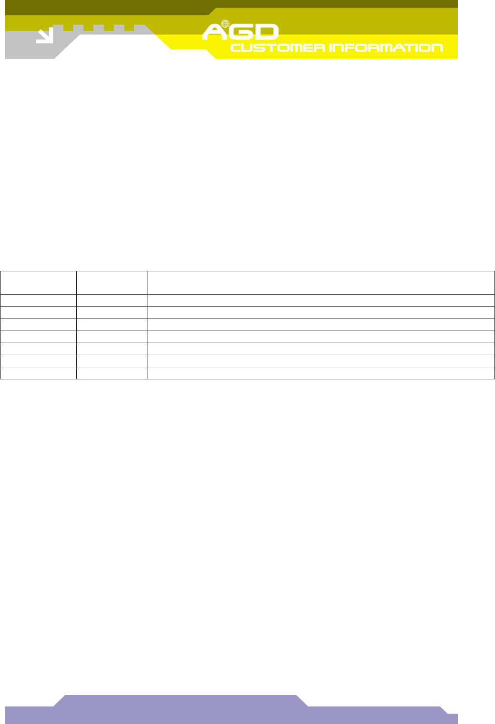
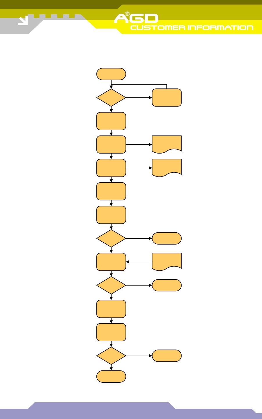
9.2 Configuration Of User Settings
Once a unit has been calibrated, a number of specified settings are adjusted, and further tests are
carried out to ensure the unit is operating within acceptable limits (please refer to Figure 3 overleaf).
Table 5 summarises the user settings which are adjusted, showing the tests carried out, and the pass
\ fail criteria applied to each test.
Test
Description
Pass \ Fail Limits
Comments
11
Check for correct operation of RS422
Receive OK
Transmit OK
At 115200 baud
12
Check serial number via RS422 port
Same as serial number
set previously
Serial number cannot
be adjusted via RS422
for security
13
Message OK
Frame rate 40FPS
Cosine set to 22º
Message should start
automatically on power
up
Table 5 User Settings
,
© AGD Systems Ltd 2010. All rights reserved., the information contained in this document is the property of AGD Systems Ltd., and is supplied
without liability for errors or omissions. AGD315 User Manual Page 12 of 12
Figure 3 shows the process by which the user settings are configured:
Set ranging mode
Set 40 FPS
Set 22 degrees
(via LW port)
Enter serial
number
xxxxx-yyyyy
(via LW port)
Reboot unit
RS422 OK ?
YES
NO
START
Unit
calibrated ? Calibrate unit
YES
NO
Values stored in
parameter
EEPROM
Connect to unit via
Livewire port
Values stored in
secure
EEPROM
Enable
RS422 port
Set baud rate
(115200)
Check
serial number
(via RS422 port)
FAIL (TEST 11)
xxxxx-yyyyy from
secure EEPROM
Serial
number OK
?
YES
NO FAIL (TEST 12)
Enable ranging
diagnostic
message
Reboot unit
Message OK ?
YES
NO FAIL (TEST 13)
END
TEST
11
TEST
12
TEST
13
Figure 3 Configuration Of User Settings