AGD SYSTEMS MC-133 AGD-T7813-125 MC-133 User Manual Farbgutstrasse 3 CH 9008 St
AGD SYSTEMS LTD AGD-T7813-125 MC-133 Farbgutstrasse 3 CH 9008 St
OEM Instructions
RFbeam Microwave GmbH
© RFbeam Microwave GmbH www.rfbeam.ch
Page 1/5
Introduction
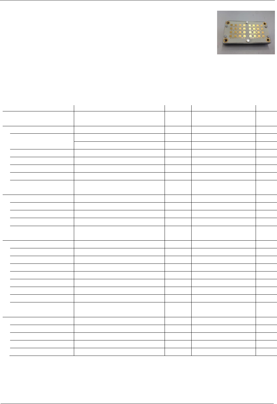
This document describes the AGD-T7813 modules Issue ‚1’.
This module has the following features:
Improved Ceramics Material (Temex E2036)
RF-Transistor with higher gain
Adjusted PCB Layout with tighter coupling for Resonator (lower loss)
Electrical Specification
Parameter
Conditions / Notes
Symbol
Min
Typ
Max
Unit
Operating conditions
Supply voltage
Vcc
3.15
3.3
6.0
V
Supply current
Module enabled
Icc1
40
60
80
mA
RF-Part disabled
Icc2
5
10
mA
VCO input voltage
Uvco
0
5.5
V
VCO pin resistance
Internal pulldown 100k
Rvco
100k
Operating temperature
Top
-20
+70
°C
Storage temperature
Tst
-40
+85
°C
Power down/Enable
RF power down
Input tied high with pullup 100k
VIH1
2.7
Vcc+ 0.3
V
RF enable
VIL1
-0.2
0.7
V
Minimum enable time
RF-part fully functional
ton
5
s
Maximum hold time
LP capacitor charge error < 10%
toff
2
ms
Transmitter
Transmitter frequency
UVCO= 3.0V, Tamb= 25°C
fTX
24.120
24.125
24.130
GHz
Frequency drift vs temp.
Vcc=3.3V, -20°C .. +70°C
fTX
-0.27
MHz/°C
Frequency tuning range (VCO)
UVCO= 1V .. 5V
fvco
35
50
70
MHz
VCO sensitivity
Svco
12.5
MHz/V
VCO Modulation Bandwidth
f=1MHz
BVCO
200
kHz
Output power
EIRP
PTX
+13
+16
+20
dBm
Output power deviation
Full VCO tuning range
PTX
+/- 2
dBm
Spurious emission
According to ETSI 300 440
Pspur
-30
dBm
Receiver
Antenna gain
FTX=24.125GHz
GAnt
15
dBi
LNA gain
FRX=24.125GHz
GLNA
9
dB
Mixer Conversion loss
fIF =500Hz
Dmixer
-2.0
dB
Receiver sensitivity
fIF =500Hz, B=1kHz, S/N=6dB
PRX
-114
dBm
Overall sensitivity
fIF =500Hz, B=1kHz, S/N=6dB
Dsystem
-130
dBc
Datasheet
AGD-T7813-125 Issue ‘1’ MC-133
RFbeam Microwave GmbH
Datasheet
AGD-T7813-125 Issue ‘1’ MC-133
© RFbeam Microwave GmbH www.rfbeam.ch
Page 2/5
Parameter
Conditions / Notes
Symbol
Min
Typ
Max
Unit
IF output
IF output impedance
RIF
100
IF Amplifier gain
GIF
30
dB
I/Q amplitude balance
fIF =500Hz, UIF=100mVpp
UIF
3
dB
I/Q phase shift
fIF =500Hz, UIF=100mVpp
70
90
110
°
IF frequency range
-3dB Bandwidth
fIF_AC
20
500k
Hz
IF noise voltage
fIF =500Hz
UIFnoise
1.0
3.2
7.9
V/Hz
fIF =500Hz
UIFnoise
-120
-110
-102
dBV/Hz
IF output offset voltage
Vcc = 3.3V
Uos_AC
1.0
1.5
2.0
V
Supply rejection
Rejection supply pins to IF outputs, 1kHz
Dsupply
26
dB
Antenna
Horizontal -3dB beamwidth
E-Plane
W
28
30
32
°
Vertical -3dB beamwidth
H-Plane
W
28
30
32
°
Horiz. sidelobe suppression
D
-20
-25
dB
Vert. sidelobe suppression
D
-16
-20
dB
Body
Outline Dimensions
connector left unconnected
35*65*17
mm3
Weight
62
g
Connector
8
pins
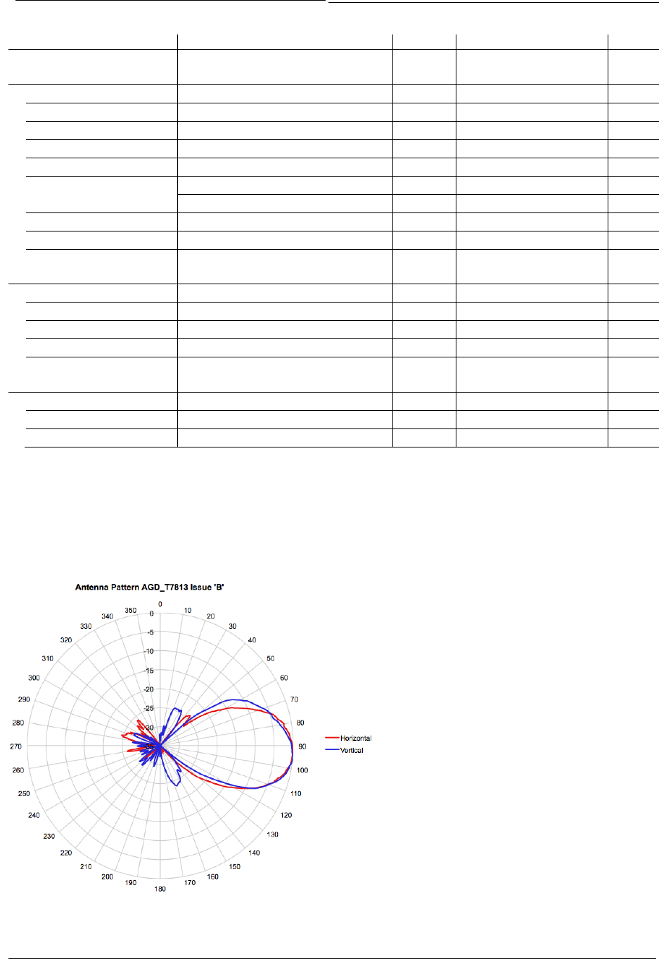
Antenna Pattern
Typical Antenna Pattern for one antenna (RX- or TX-side). Measured at 24.200GHz:
RFbeam Microwave GmbH
© RFbeam Microwave GmbH www.rfbeam.ch
Page 3/5
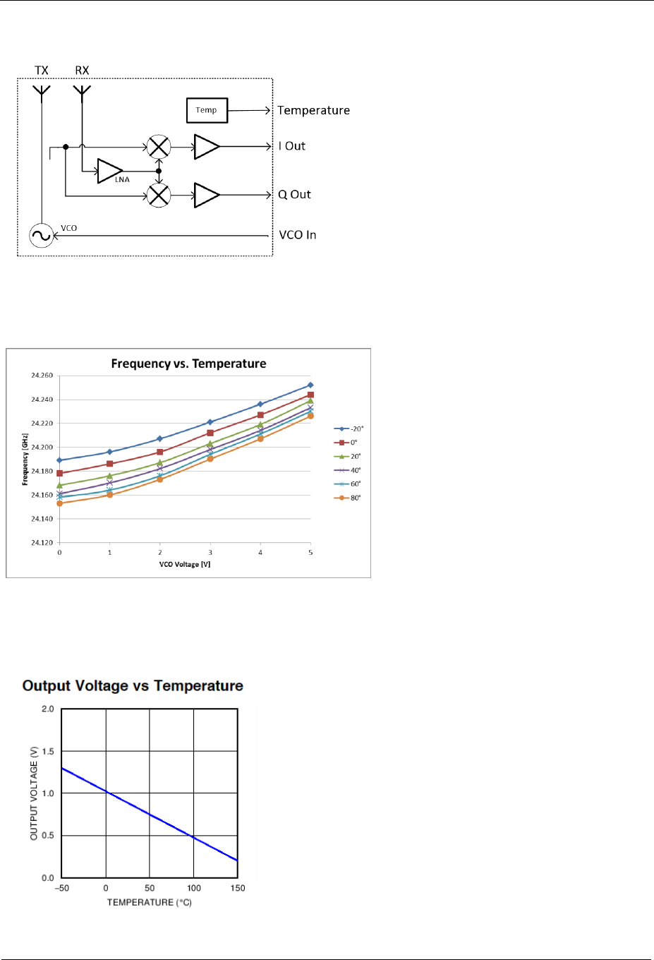
Block diagram
Frequency vs. VCO-Voltage and Temperature
Pin 8 voltage vs. Temperature
Datasheet
AGD-T7813-125 Issue ‘1’ MC-133
RFbeam Microwave GmbH
© RFbeam Microwave GmbH www.rfbeam.ch
Page 4/5
Connector Pinout
On module side a Samtec HW-04-15-F-D-325-SM connector with the following pinout is used:
1: /Enable Enable/Disable RF-part. Connect to 0V for normal operation
2: +3.3V Power Supply. Connect to +3.3V (3.15V .. 6.0V)
3: GND Ground connection. Connect to 0V
4: Q Out Analog Output Q-Channel
5: I Out Analog Output I-Channel
6: VCO Frequency control input. A voltage between 1..5V adjusts
TX Frequency by 0 .. 50MHz. Can be used for FSK or FMCW
7: S&H Sample&Hold Switch Analog Output. Leave it open or connect
to +3.3V for normal operation
8: Temp Temperature Sensor output of LMT84 temperature sensor
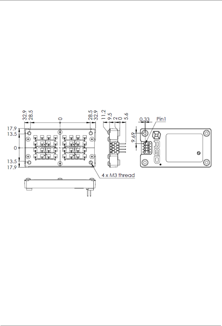
Mechanical Drawing
FCC Labelling Information: (label to be placed into the recess position * shown in the
mechanical drawing above
FCC ID: WH3 -MC-133
AGD-T7813-125 (MC-133)
Frequency 24.125GHz
Issue 1
Serial No: in barcode or datamatrix format
*
Datasheet
AGD-T7813-125 Issue ‘1’ MC-133

Document History
Author:
Date: Léon Audergon, RFbeam Microwave GmbH, CH-9008 St. Gallen
August 25th 2015
Version:
Changes: 1.1
I- and Q-outputs exchanged
Different drawings added
© RFbeam Microwave GmbH www.rfbeam.ch Page 5/5
This device complies with Part 15 of the FCC Rules.
Operation is subject to the following two conditions:
(1) This device may not cause harmful interference, and
(2) This device must accept any interference received, including interference that
may cause undesired operation.
This equipment complies with FCC radiation exposure limits set forth for an
uncontrolled environment. End users must follow the specific operating
instructions for satisfying RF exposure compliance such that the module should
not be installed in equipment intended to be used within 20cm of the body.
This transmitter must not be co-located or operating in conjunction with any other
antenna or transmitter.
Changes or modifications not expressly approved by AGD SYSTEMS
Ltd could void the user's authority to operate the equipment
FCC Approval
Manufacturers of mobile or fixed devices incorporating MC-133 modules are
authorized to use the FCC Grants of the MC-133 modules for their own final
products according to the conditions referenced in these documents. In this case,
the FCC label of the module shall be visible from the outside, or the host device
shall bear a second label stating "Contains FCC ID: WH3-3-MC-133".
RFbeam Microwave GmbH
Datasheet
AGD-T7813-125 Issue ‘1’ MC-133