ALE USA OAW-AP1101 Alcatel-Lucent Enterprise OmniAccess AP User Manual
ALE USA Inc. Alcatel-Lucent Enterprise OmniAccess AP Users Manual
UserManual.wiki
>
ALE USA
>
OAW AP1101 User Manual
Users Manual
Navigation menu
Upload a User Manual
Namespaces
Wiki Guide
HTML
PDF
Info
Views
User Manual
Discussion / Help
Navigation
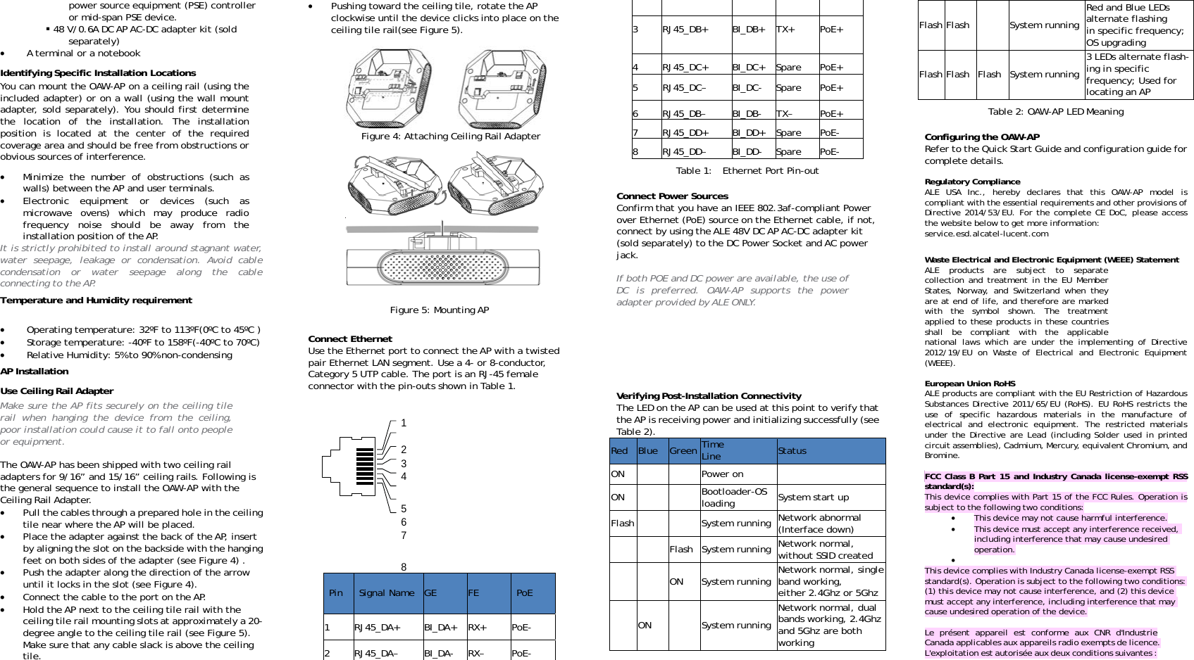
![AlcateOAW-AGuide 060436-1*060 enterprise.aAlcatel-LuceAlcatel-LuceHolding, vtrademarks presented isaffiliates as(2016) This docgeneral pnotices tIt’s recominstallatioperforme Unpa WLAis refactosupp Insta Instainsta Insta Insta Insta Verif Conf el-Lucent EnteAP Access Poin 1 Rev. A 436-11 Realcatel-lucent.com ent and the Alcatel-Luceent. To view other trademavisit: enterprise.alcatel-are the property of thei subject to ALE without nossumes any responsibility cument describes process of installathat need to be admmend that the enton. All new AP ed in the following sack the AP and checAN Planning. Usuallyequired before instaors to consider suchply to the AP, locatioall the AP bracket oall communications alled) label and testall each AP to brackall patch cord into pall patch cord into ofy post-installation figure each AP. erprise nt Installationev. A* ent Enterprise logo are tarks used by affiliated com-lucent.com/trademarks. ir respective owners. Theotice. Neither ALE Holdingy for inaccuracies contathe packaging, Ation as well as wadressed prior to inire document be reainstallations are sequence: ck all items in the by, a comprehensive sallation. There are mh as coverage area, on of AP brackets, eon wall or ceiling. outlet (if new outlet. ket. port on AP. outlet. connectivity. n trademarks of mpanies of ALE All other e information g nor any of its ained herein. AP layout, arning and nstallation. ad prior to typically box site survey many power etc. et is Access points aresubject to gadministrators configuration ancomply with locaaccess point mustto the location whPackage Contents Access Point Dimen1.1 inc Weight 9/16" Ceiling 15/16" Ceilin Quick Start G Installation User Guide A Fi Inform your ALE smissing, or damagcarton, including Use these materiato the supplier if nfor use with the sold separately.representative for Device view The OAW-AP acceslight that indicatee radio transmissiogovernmental regwho are respd operation of aal broadcast regult use channel assighere the access pois t nsions(HxWxD): 6.1 iches (15.5 cm x 15.t: 270g g Rail Adapter ng Rail Adapter Guide Guide Access Card igure1: Product Pacsales representativeged parts. If possib the original packials to repack and reneeded. Additional OAW- AP1101 acce. Contact your r details. ss point is equipped es different status w Hidon devices and argulation. Networponsible for thaccess points muslations. Specificallgnments appropriatint will be deployedinches x 6.1 inches 5 cm x 2.8 cm) cking e of incorrect, ble, retain the ing materials. eturn the unit mounting kits ess points are ALE sales with one hidden LEwith different color.denLEDLocationre rk he st y, te d. x ED FItem Name EthernePort ConsolePort DC PowSocket SecurityLock Slo Pre-instFCC StaSecurityFigure 2: OAW-AP AcFigure 3: OAW-AP ASpecificationset The OAW-AP10/100/1000BMDI/MDX wiree The console connector andterminal for dwer The OAW-AP hsocket to suAC-to-DC powavailable, an(sold separateOAW-AP. y ot The OAW-AP islot for addititallation atement: Improper y Lock ConsoReset ccess Point (Front VAccess Point (Back Vs P is equipped Base-T (RJ-45) aed-network connect port is an RJ-d can be used to cdirect local managemhas a single 48V DCupport powering wer adapter, If optional AC-DC ely) can be used tos equipped with a sonal security. installation of acceole Ethernet DC Power SockView) View) with one uto-sensing, tivity port. -45 female connect to a ment. C power jack through an PoE is not adapter kit o power the security lock ess points in ket the United Statewill be in violatintentional violaFCC for immediasubject to forfeiLow power radioGHz bands. Pleadetails on restri For product avachannel 1~11 channels is not indoor use. Pour les produitmarché, seul leSélection d'autrutilisation en in Dynamic Frequein the bands 5650-5725 MHz. Sélection dynamdispositifs fonct5470-5600 MHz e The device for oonly for indoor interference to les dispositifs fosont réservés unutilisation à l’ibrouillage préjmobiles utilisan Users should alsallocated as prbands 5250-5350radars could cLE-LAN devices. De plus, les utilles utilisateurs désignés utilisapriorité) pour lMHz et que ceset/ou des domm Pre-Installation Before installingthat you have th 4- or 8-conrequired le One of the IEEE (Pes configured to nontion of the FCC ruleation may result in ate termination of iture (refer to 47 CFo LAN product operase refer to the Actions. ailable in the USA/can be operated. possible. This dets disponibles aux Ée canal 1 à 11 peres canaux n'est patérieur uniquementncy Selection (DFS)5250- 5350 MHz, mique de fréquentionnant dans les baet 5650-5725 MHz. operation in the buse to reduce the co-channel mobile sonctionnant dans la niquement pour unentérieur afin de rjudiciable aux syst les mêmes canauxso be advised that himary users (i.e. p0 MHz and 5650-585cause interference lisateurs devraient de radars de hteurs principaux (es bandes 5250-53s radars pourraientmages aux dispositifs Checklist g your OAW-AP acche following items: nductor, CAT5 or bength. e following power so 802.3af-compliant PoE) source (The POn-US model controlles. Any such willful a requirement by operation and mayFR 1.80).EU Statemating in 2.4 GHz anLE OS User Guide /Canada market, o Selection of otevice is restricted États-Unis / Canadauvent être exploitas possible. Pour ut. for devices operat 5470-5600 MHz ances (DFS) pour andes 5250-5350 Mand 5150–5250 MHz potential for harmsatellite systems. bande 5150-5250 Me. réduire les risques stèmes de satellix. high-power radars priority users) of 50 MHz and that the and/or damage aussi être avisés qhaute puissance s(c.-à-d., qu’ils ont350 MHz et 5650-58t causer du brouillafs LAN-EL. cess point, be suretter UTP cable of ources: Power over EtherneOE source can be anlers l or the y be ent: nd 5 for only her for a du tés. une ting and les Hz, z is mful MHz de ites are the ese to que ont t la 850 age e et ny 註解[warni註解[Statem[l1]:AddFCCandICngstatement[l2]:5GDFSFCCanmentC2.4GdICwarning](https://usermanual.wiki/ALE-USA/OAW-AP1101/User-Guide-3095682-Page-1.png)
![(1) l'appareil ne doit pas produire de brouillage, et (2) l'utilisateur de l'appareil doit accepter tout brouillage radioélectrique subi, même si le brouillage est susceptible d'en compromettre le fonctionnement. Any changes or modifications to this unit not expressly approved by the party responsible for compliance could void the user’s authority to operate this equipment. This equipment has been tested and compliant with the limits for a Class B digital device under part 15 of the FCC Rules. This equipment generates,uses and can radiate radio frequency energy. If it is not installed and used in accordance with ALE’s instructions, it may cause harmful interference. If this equipment does cause interference, which can be determined by turning the equipment off and on, the user is encouraged to correct the interference by one or more of the following ways: Reorient or relocate the antenna. Increase the separation between the equipment and other devices. Connect the equipment to an outlet on a circuit different from that to which the other device is connected. Consult the dealer or an experienced radio technician for help. Complies with the Class B limits for radio noise emissions as set out in the interference-causing equipment standard entitled “Digital Apparatus,” ICES-003 of Industry Canada. EU Regulatory Conformance ALE USA, Inc., hereby declares that this OAW-AP model is compliant with the essential requirements and other provisions of Directive 2014/53/EU. California Proposition 65 Warning WARNING: This product contains chemicals known to the State of California to cause cancer and birth defects or other reproductive harm. RF Radiation Exposure Statement: This equipment complies with FCC,IC and CE RF radiation exposure limits. This equipment should be installed and operated with a minimum distance of 20 cm between the equipment and a human’s body for 2.4 GHz and 5 GHz operations. This transmitter must not be co-located or operating in conjunction with any other antenna or transmitter. Cet équipement est conforme aux limites d'exposition aux rayonnements IC établies pour un environnement non contrôlé. Cet équipement doit être installé et utilisé avec un minimum de 20 cm de distance entre la source de rayonnement et votre corps. For Model OWA-AP1101, the frequency and the maximum transmitted power are listed below: 2412-2472MHz: 19.97dBm 5180-5240MHz: 22.70dBm 5260-5320MHz: 22.89dBm 5500-5700MHz: 28.27dBm 註解[l3]:AddIndustryCanadastatement註解[l4]:RepeatedCEDoC,shouldbedeleted註解[l5]:AddICofCanada註解[l6]:AddFrenchWarningofIC註解[l7]:AddCEREDnewrequirement](https://usermanual.wiki/ALE-USA/OAW-AP1101/User-Guide-3095682-Page-3.png)