ALE USA OAW-AP1101 Alcatel-Lucent Enterprise OmniAccess AP User Manual
ALE USA Inc. Alcatel-Lucent Enterprise OmniAccess AP Users Manual
ALE USA >
Users Manual
Alcat
e
OAW-
A
Guide
060436-1
*060
enterprise.
a
Alcatel-Luc
e
Alcatel-Luc
e
Holding,
v
trademarks
presented is
affiliates a
s
(2016)
This do
c
general
p
notices t
It’s reco
m
installati
o
perform
e
Unp
a
WL
A
is r
e
fact
o
sup
p
Inst
a
Inst
a
inst
a
Inst
a
Inst
a
Inst
a
Veri
f
Con
f
e
l-Lucent Ent
e
A
P Access Poi
n
1 Rev. A
436-11 R
e
a
lcatel-lucent.com
e
nt and the Alcatel-Luc
e
e
nt. To view other tradem
a
v
isit: enterprise.alcatel
-
are the property of the
i
subject to ALE without n
o
s
sumes any responsibilit
y
c
ument describes
p
rocess of installa
t
hat need to be ad
m
mend that the ent
o
n. All new AP
e
d in the following
s
a
ck the AP and che
c
A
N Planning. Usuall
y
e
quired before inst
a
o
rs to consider suc
h
p
ly to the AP, locati
o
a
ll the AP bracket
o
a
ll communications
a
lled) label and tes
t
a
ll each AP to brac
k
a
ll patch cord into
p
a
ll patch cord into
o
f
y post-installation
f
igure each AP.
e
rprise
n
t Installatio
n
e
v. A*
e
nt Enterprise logo are
t
a
rks used by affiliated co
m
-
lucent.com/trademarks.
i
r respective owners. Th
e
o
tice. Neither ALE Holdin
g
y
for inaccuracies cont
a
the packaging,
A
t
ion as well as w
a
dressed prior to i
n
ire document be re
a
installations are
s
equence:
c
k all items in the
b
y
, a comprehensive
s
a
llation. There are
m
h
as coverage area,
o
n of AP brackets,
e
o
n wall or ceiling.
outlet (if new outl
e
t
.
k
et.
p
ort on AP.
o
utlet.
connectivity.
n
t
rademarks of
m
panies of ALE
All other
e
information
g
nor any of its
a
ined herein.
A
P layout,
a
rning and
n
stallation.
a
d prior to
typically
b
ox
s
ite survey
m
any
power
e
tc.
e
t is
Access points ar
e
subject to
g
administrators
configuration an
comply with loc
a
access point mus
t
to the location w
h
Package Content
s
Access Poin
t
Dime
n
1.1 in
c
Weigh
t
9/16" Ceilin
g
15/16" Ceili
n
Quick Start
G
Installation
User Guide
A
F
i
Inform your ALE
s
missing, or dama
g
carton, including
Use these materi
a
to the supplier if
n
f
or use with the
sold separately
.
representative fo
r
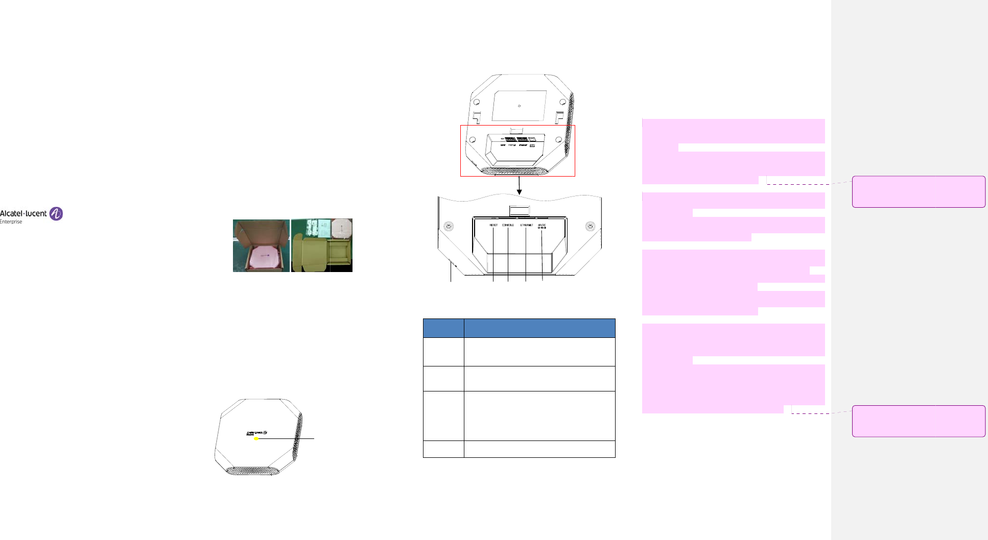
Device view
The OAW-AP acce
s
light that indicat
e
e
radio transmissi
o
g
overnmental re
g
who are res
p
d
operation of
a
a
l broadcast
regu
l
t
use channel assi
g
h
ere the
access po
i
s
t
n
sions(HxWxD): 6.1
i
c
hes (15.5 cm x 15.
t
: 270g
g
Rail Adapter
n
g Rail Adapter
G
uide
Guide
A
ccess Card
i
gure1: Product Pa
c
s
ales representativ
e
g
ed parts. If possi
b
the original pack
i
a
ls to repack and r
e
n
eeded. Additional
OAW- AP1101 acc
e
.
Contact your
r
details.
s
s point is equipped
e
s different status
w
Hid
o
n devices and a
r
g
ulation. Netwo
r
p
onsible for t
h
a
ccess points mu
s
l
ations. Specificall
g
nments appropria
t
i
nt will be deploye
d
i
nches x 6.1 inches
5 cm x 2.8 cm)
c
king
e
of incorrect,
b
le, retain the
i
ng materials.
e
turn the unit
mounting kits
e
ss points are
ALE sales
with one hidden L
E
w
ith different color.
denLEDLocation
r
e
r
k
h
e
s
t
y,
t
e
d
.
x
E
D
F
Item
Name
Ethern
e
Port
Consol
e
Port
DC Po
w
Socket
Securit
y
Lock Sl
o
Pre-ins
t
FCC St
a
Securit
y
F
igure 2: OAW-AP A
c
Figure 3: OAW-AP
A
Specification
s
e
t The OAW-A
P
10/100/1000
B
MDI/MDX wir
e
e
The console
connector an
d
terminal for
d
w
er The OA
W
-AP
h
socket to s
u
AC-to-DC po
w
available, an
(sold separat
e
OAW-AP.
y
o
t The OAW-AP i
slot for additi
t
allation
a
tement: Improper
y
Lock Cons
o
Reset
c
cess Point (Front
V
A
ccess Point (Back
V
s
P
is equipped
B
ase-T (RJ-45) a
e
d-network connec
t
port is an RJ
-
d
can be used to
c
d
irect local manage
m
h
as a single 48V DC
u
pport powering
w
er adapter, If
optional AC-DC
e
ly) can be used t
o
s equipped with a
s
onal security.
installation of acc
e
o
le Ethernet
DC Power
Soc
k
V
iew)
V
iew)
with one
uto-sensing,
t
ivity port.
-
45 female
c
onnect to a
m
ent.
C
power jack
through an
PoE is not
adapter kit
o
power the
s
ecurity lock
e
ss points in
k
e
t
the United Stat
e
will be in viola
t
intentional viol
a
FCC for immedi
a
subject to forfe
i
Low power radi
o
GHz bands. Ple
a
details on restri
For product av
a
channel 1~11
channels is not
indoor use.
Pour les produi
t
marché, seul l
e
Sélection d'aut
r
utilisation en in
Dynamic Freque
in the bands
5650-5725 MHz.
Sélection dyna
m
dispositifs fonc
t
5470-5600 MHz
e
The device for
o
only for indoor
interference to
les dispositifs f
o
sont réservés u
n
utilisation à l’i
brouillage pré
j
mobiles utilisan
Users should al
s
allocated as pr
bands 5250-535
0
radars could
c
LE-LAN devices.
De plus, les uti
l
les utilisateurs
désignés utilisa
priorité) pour l
MHz et que ce
s
et/ou des dom
m
Pre-Installation
Before installin
g
that you have t
h
4- or 8-co
n
required le
One of th
e
IEEE
(
P
e
s configured to no
n
t
ion of the FCC rul
e
a
tion may result in
a
te termination of
i
ture (refer to 47 C
F
o
LAN product oper
a
se refer to the A
ctions.
a
ilable in the USA
/
can be operated.
possible. This d
e
t
s disponibles aux
É
e
canal 1 à 11 pe
r
es canaux n'est p
a
térieur uniquemen
t
ncy Selection (DFS)
525
0
- 5350 MHz,
m
ique de fréque
n
t
ionnant dans les b
a
e
t 565
0
-5725 MHz.
o
peration in the b
use to reduce the
co-channel mobile
s
o
nctionnant dans la
n
iquement pour un
e
ntérieur afin de
r
j
udiciable aux sy
s
t les mêmes canau
x
s
o be advised that
h
imary users (i.e.
p
0
MHz and 5650-58
5
c
ause interferenc
e
l
isateurs devraient
de radars de
h
teurs principaux
(
es bandes 5250-5
3
s
radars pourraien
t
m
a
g
es aux dispositi
fs
Checklist
g
your OAW-AP ac
c
h
e following items:
n
ductor, CAT5 or be
ngth.
e
following power s
o
802.3af-compliant
P
oE) source (The P
O
n
-US model control
l
e
s. Any such willfu
l
a requirement by
operation and ma
y
F
R 1.80).EU Statem
ating in 2.4 GHz a
n
LE OS User Guide
/
Canada market,
o
Selection of ot
e
vice is restricted
É
tats-Unis / Canad
a
uvent être exploi
t
a
s possible. Pour
u
t
.
for devices opera
t
5470-5600 MHz
a
n
ces (DFS) pour
a
ndes 525
0
-5350 M
and 5150–5250 MH
z
potential for har
m
s
atellite systems.
bande 515
0
-5250
M
e
.
r
éduire les risques
s
tèmes de satell
i
x
.
h
igh-power radars
p
riority users) of
5
0 MHz and that th
e
and/or damage
aussi être avisés
q
h
aute puissance s
(
c.-à-d., qu’ils on
t
3
50 MHz et 565
0
-5
8
t
causer du brouill
a
fs
LA
N
-EL.
c
ess point, be sur
e
tter UTP cable of
o
urces:
Power over Ethern
e
O
E source can be a
n
l
ers
l
or
the
y
be
ent:
n
d 5
for
o
nly
her
for
a
du
t
és.
u
ne
t
ing
a
nd
les
Hz,
z
is
m
ful
M
Hz
de
i
tes
are
the
ese
to
q
ue
ont
t
la
8
50
a
ge
e
e
t
n
y
註解
[
warni
註解
[
State
m
[
l1]:AddFCCandI
C
n
gstatement
[
l2]:5GDFSFCCan
m
ent
C
2.4G
dICwarning
power source equipment (PSE) controller
or mid-span PSE device.
48 V/0.6A DC AP AC-DC adapter kit (sold
separately)
A terminal or a notebook
Identifying Specific Installation Locations
You can mount the OAW-AP on a ceiling rail (using the
included adapter) or on a wall (using the wall mount
adapter, sold separately). You should first determine
the location of the installation. The installation
position is located at the center of the required
coverage area and should be free from obstructions or
obvious sources of interference.
Minimize the number of obstructions (such as
walls) between the AP and user terminals.
Electronic equipment or devices (such as
microwave ovens) which may produce radio
frequency noise should be away from the
installation position of the AP.
It is strictly prohibited to install around stagnant water,
water seepage, leakage or condensation. Avoid cable
condensation or water seepage along the cable
connecting to the AP.
Temperature and Humidity requirement
Operating temperature: 32ºF to 113ºF(0ºC to 45ºC )
Storage temperature: -40ºF to 158ºF(-40ºC to 70ºC)
Relative Humidity: 5% to 90% non-condensing
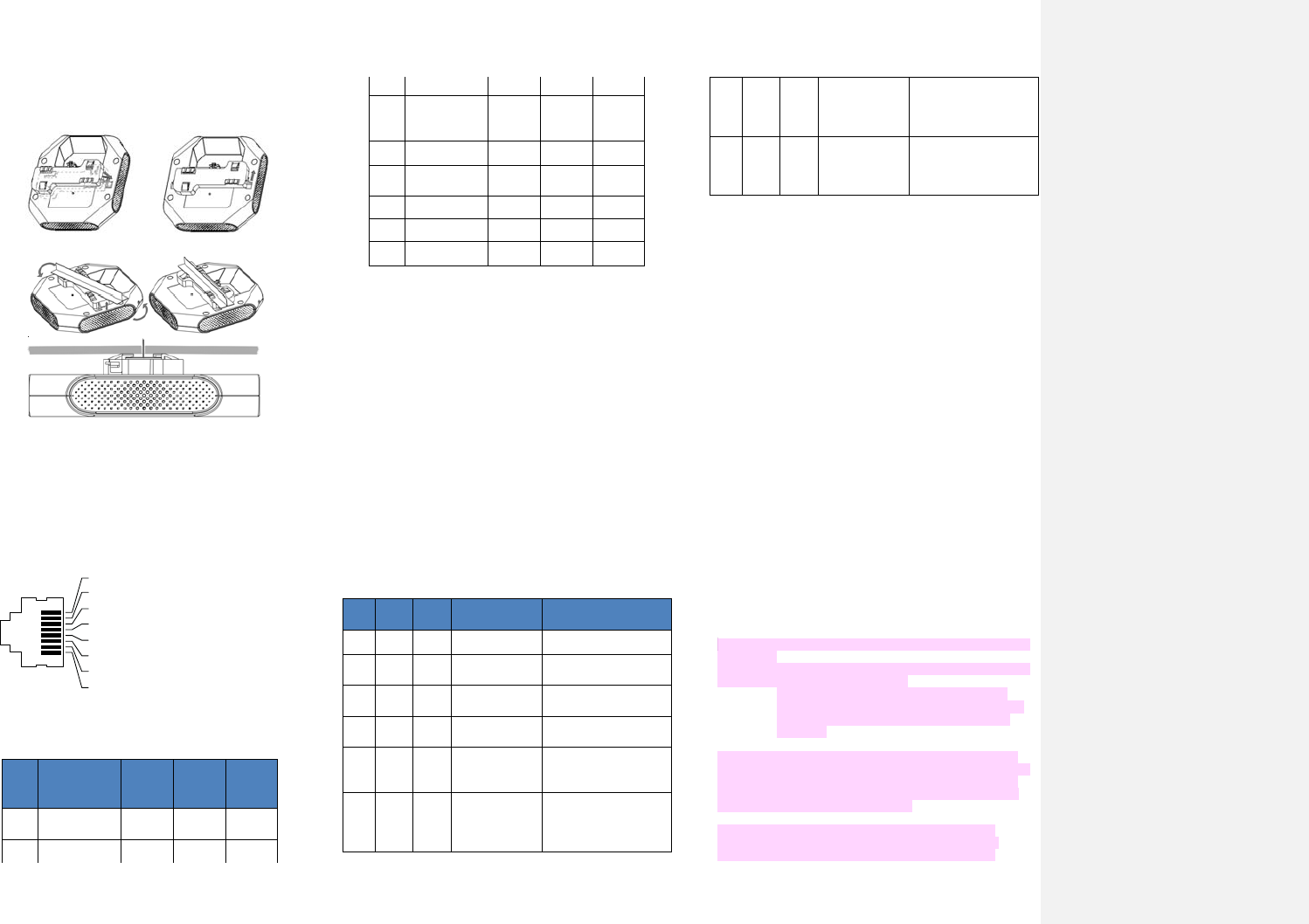
AP Installation
Use Ceiling Rail Adapter
Make sure the AP fits securely on the ceiling tile
rail when hanging the device from the ceiling,
poor installation could cause it to fall onto people
or equipment.
The OAW-AP has been shipped with two ceiling rail
adapters for 9/16” and 15/16” ceiling rails. Following is
the general sequence to install the OAW-AP with the
Ceiling Rail Adapter.
Pull the cables through a prepared hole in the ceiling
tile near where the AP will be placed.
Place the adapter against the back of the AP, insert
by aligning the slot on the backside with the hanging
feet on both sides of the adapter (see Figure 4) .
Push the adapter along the direction of the arrow
until it locks in the slot (see Figure 4).
Connect the cable to the port on the AP.
Hold the AP next to the ceiling tile rail with the
ceiling tile rail mounting slots at approximately a 20-
degree angle to the ceiling tile rail (see Figure 5).
Make sure that any cable slack is above the ceiling
tile.
Pushing toward the ceiling tile, rotate the AP
clockwise until the device clicks into place on the
ceiling tile rail(see Figure 5).
Figure 4: Attaching Ceiling Rail Adapter
Figure 5: Mounting AP
Connect Ethernet
Use the Ethernet port to connect the AP with a twisted
pair Ethernet LAN segment. Use a 4- or 8-conductor,
Category 5 UTP cable. The port is an RJ-45 female
connector with the pin-outs shown in Table 1.
1
2
3
4
5
6
7
8
Pin
Signal Name
GE FE PoE
1 RJ45_DA+ BI_DA+ RX+ PoE-
2 RJ45_DA– BI_DA- RX– PoE-
3 RJ45_DB+ BI_DB+ TX+ PoE+
4 RJ45_DC+ BI_DC+ Spare PoE+
5 RJ45_DC– BI_DC- Spare PoE+
6 RJ45_DB–
BI_DB-
TX–
PoE+
7 RJ45_DD+
BI_DD+
S
p
are
PoE-
8 RJ45_DD– BI_DD- Spare PoE-
Table 1: Ethernet Port Pin-out
Connect Power Sources
Confirm that you have an IEEE 802.3af-compliant Power
over Ethernet (PoE) source on the Ethernet cable, if not,
connect by using the ALE 48V DC AP AC-DC adapter kit
(sold separately) to the DC Power Socket and AC power
jack.
If both POE and DC power are available, the use of
DC is preferred. OAW-AP supports the power
adapter provided by ALE ONLY.
Verifying Post-Installation Connectivity
The LED on the AP can be used at this point to verify that
the AP is receiving power and initializing successfully (see
Table 2).
Red
Blue Green
Time
Line Status
ON Power on
ON Bootloader-OS
loading System start up
Flash
System running
Network
abnormal
(Interface down)
Flash
System running
Network
normal,
without SSID created
ON System running
Network
normal,
single
band working,
either 2.4Ghz or 5Ghz
ON System running
Network
normal,
dual
bands working, 2.4Ghz
and 5Ghz are both
working
Flash
Flash
System running
Red and Blue LEDs
alternate flashing
in specific frequency;
OS upgrading
Flash
Flash
Flash
System running
3 LEDs alternate flash-
ing in specific
frequency; Used for
locating an AP
Table 2: OAW-AP LED Meaning
Configuring the OAW-AP
Refer to the Quick Start Guide and configuration guide for
complete details.
Regulatory Compliance
ALE USA Inc., hereby declares that this OAW-AP model is
compliant with the essential requirements and other provisions of
Directive 2014/53/EU. For the complete CE DoC, please access
the website below to get more information:
service.esd.alcatel-lucent.com
Waste Electrical and Electronic Equipment (WEEE) Statement
ALE products are subject to separate
collection and treatment in the EU Member
States, Norway, and Switzerland when they
are at end of life, and therefore are marked
with the symbol shown. The treatment
applied to these products in these countries
shall be compliant with the applicable
national laws which are under the implementing of Directive
2012/19/EU on Waste of Electrical and Electronic Equipment
(WEEE).
European Union RoHS
ALE products are compliant with the EU Restriction of Hazardous
Substances Directive 2011/65/EU (RoHS). EU RoHS restricts the
use of specific hazardous materials in the manufacture of
electrical and electronic equipment. The restricted materials
under the Directive are Lead (including Solder used in printed
circuit assemblies), Cadmium, Mercury, equivalent Chromium, and
Bromine.
FCC Class B Part 15 and Industry Canada license-exempt RSS
standard(s):
This device complies with Part 15 of the FCC Rules. Operation is
subject to the following two conditions:
This device may not cause harmful interference.
This device must accept any interference received,
including interference that may cause undesired
operation.
This device complies with Industry Canada license-exempt RSS
standard(s). Operation is subject to the following two conditions:
(1) this device may not cause interference, and (2) this device
must accept any interference, including interference that may
cause undesired operation of the device.
Le présent appareil est conforme aux CNR d'Industrie
Canada applicables aux appareils radio exempts de licence.
L'exploitation est autorisée aux deux conditions suivantes :

(1) l'appareil ne doit pas produire de brouillage, et (2)
l'utilisateur de l'appareil doit accepter tout brouillage
radioélectrique subi, même si le brouillage est susceptible
d'en compromettre le fonctionnement.
Any changes or modifications to this unit not expressly
approved by the party responsible for compliance could
void the user’s authority to operate this equipment.
This equipment has been tested and compliant with the limits for
a Class B digital device under part 15 of the FCC Rules. This
equipment generates,uses and can radiate radio frequency energy.
If it is not installed and used in accordance with ALE’s instructions,
it may cause harmful interference. If this equipment does cause
interference, which can be determined by turning the equipment
off and on, the user is encouraged to correct the interference by
one or more of the following ways:
Reorient or relocate the antenna.
Increase the separation between the equipment and
other devices.
Connect the equipment to an outlet on a circuit
different from that to which the other device is
connected.
Consult the dealer or an experienced radio technician
for help.
Complies with the Class B limits for radio noise emissions as set
out in the interference-causing equipment standard entitled
“Digital Apparatus,” ICES-003 of Industry Canada.
EU Regulatory Conformance
ALE USA, Inc., hereby declares that this OAW-AP model is
compliant with the essential requirements and other provisions of
Directive 2014/53/EU.
California Proposition 65 Warning
WARNING: This product contains chemicals known to the State of
California to cause cancer and birth defects or other reproductive
harm.
RF Radiation Exposure Statement: This equipment complies with
FCC,IC and CE RF radiation exposure limits. This equipment
should be installed and operated with a minimum distance of 20
cm between the equipment and a human’s body for 2.4 GHz and 5
GHz operations. This transmitter must not be co-located or
operating in conjunction with any other antenna or transmitter.
Cet équipement est conforme aux limites d'exposition aux
rayonnements IC établies pour un environnement non contrôlé.
Cet équipement doit être installé et utilisé avec un minimum de
20 cm de distance entre la source de rayonnement et votre corps.
For Model OWA-AP1101, the frequency and the maximum
transmitted power are listed below:
2412-2472MHz: 19.97dBm
5180-5240MHz: 22.70dBm
5260-5320MHz: 22.89dBm
5500-5700MHz: 28.27dBm
註解[l3]:AddIndustryCanada
statement
註解[l4]:RepeatedCEDoC,shouldbe
deleted
註解[l5]:AddICofCanada
註解[l6]:AddFrenchWarningofIC
註解[l7]:AddCEREDnew
requirement