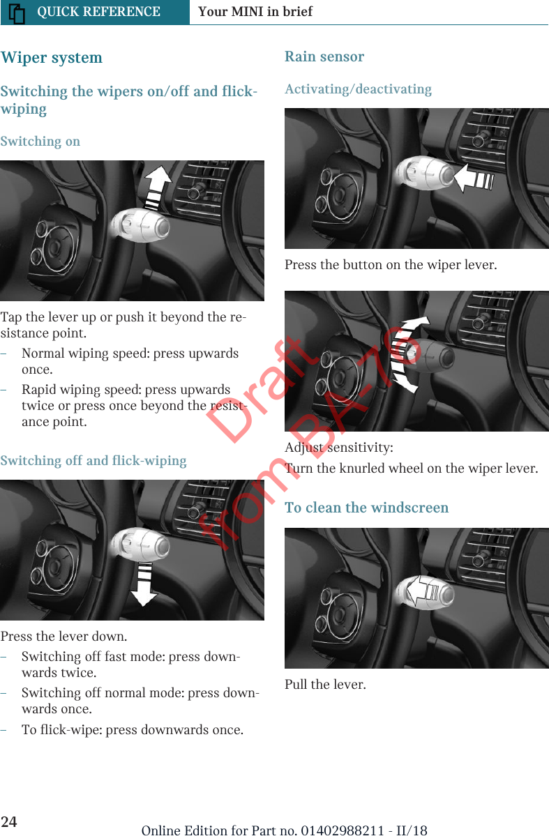
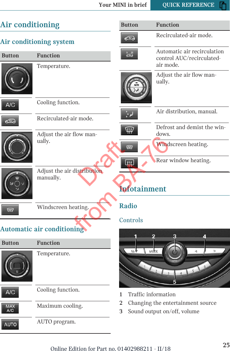
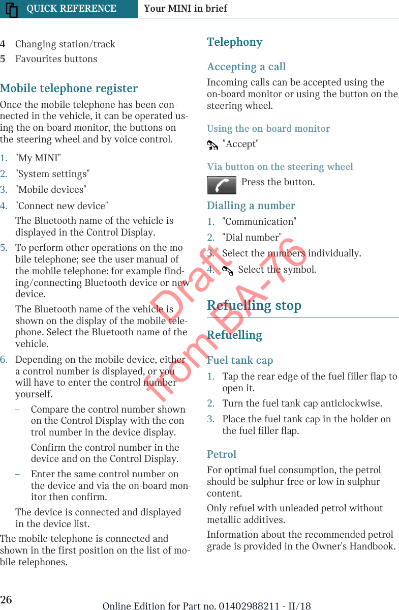
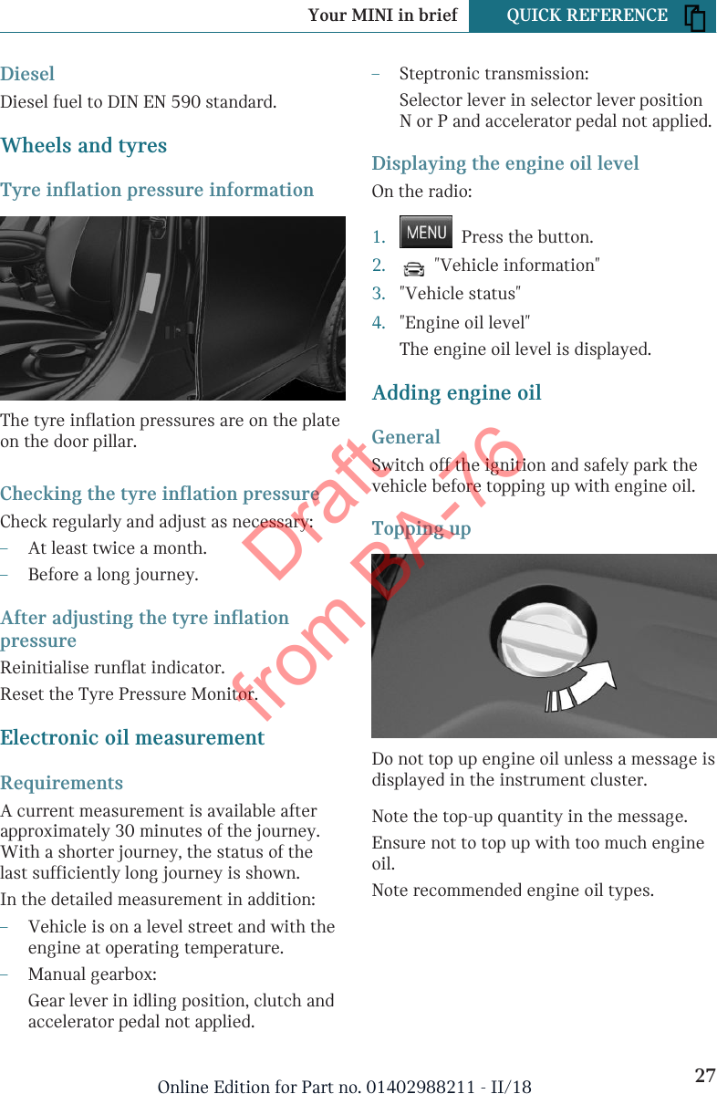
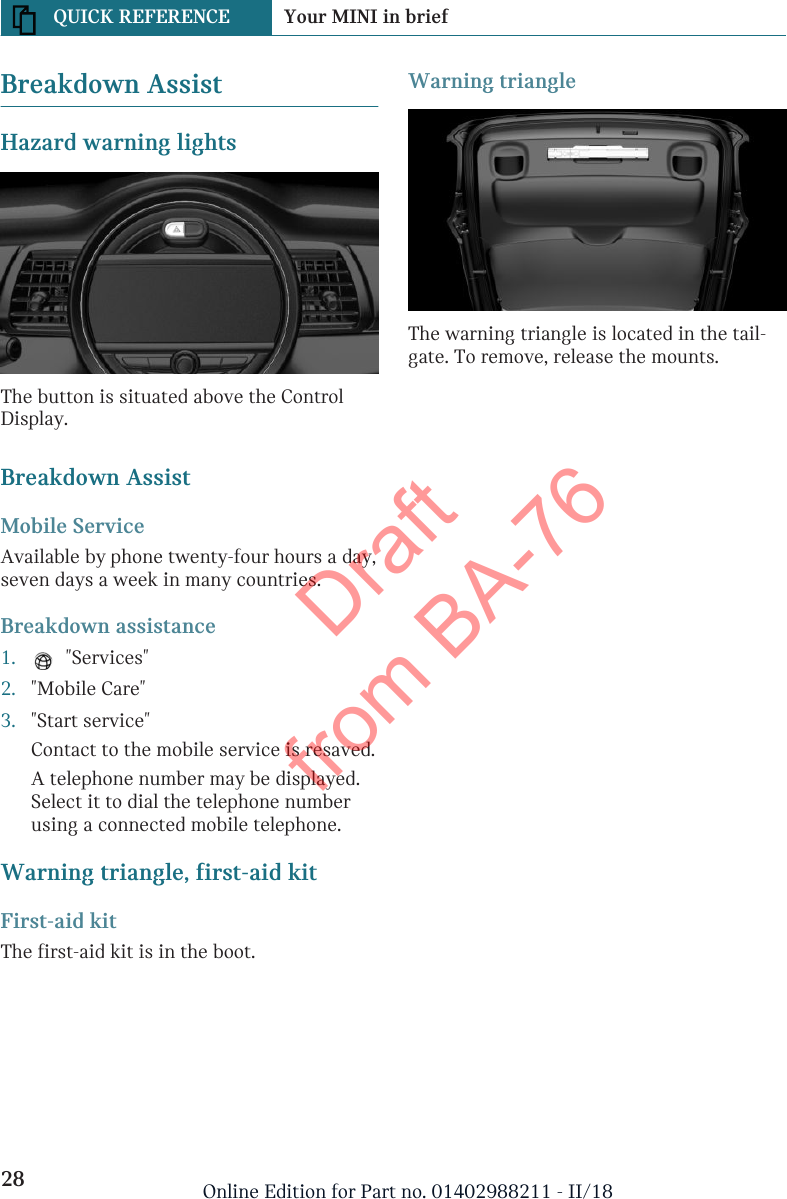
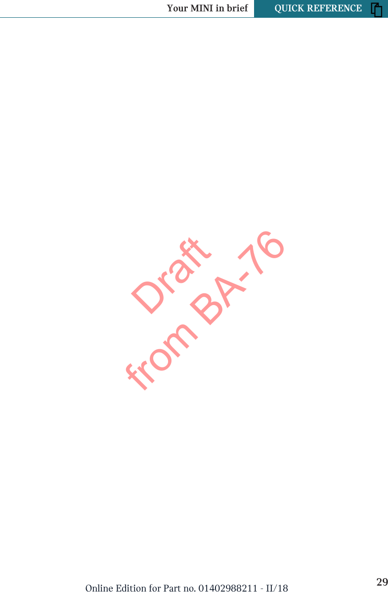
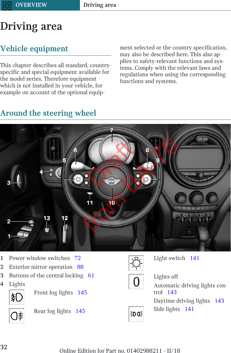
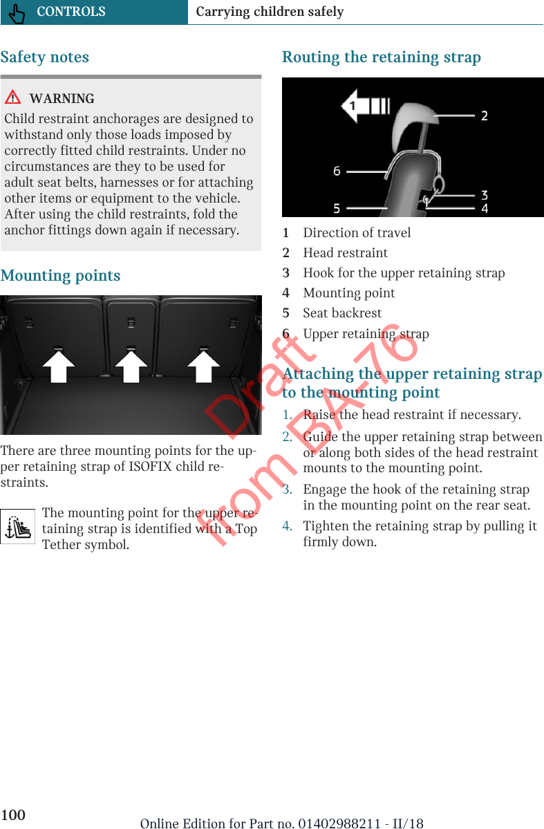
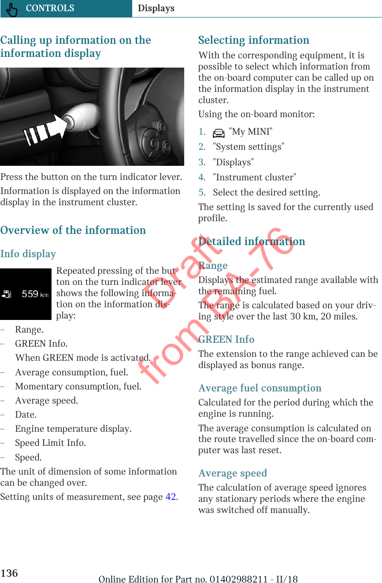
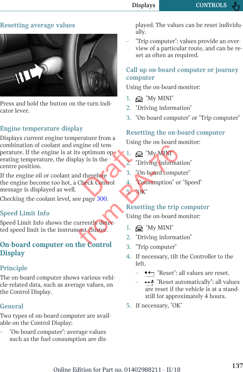
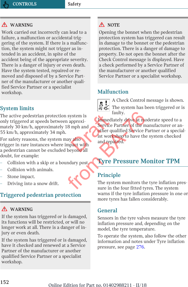
ALPS ALPINE 9ZUA153 Car Audio User Manual 05 Short Term Confidential 1

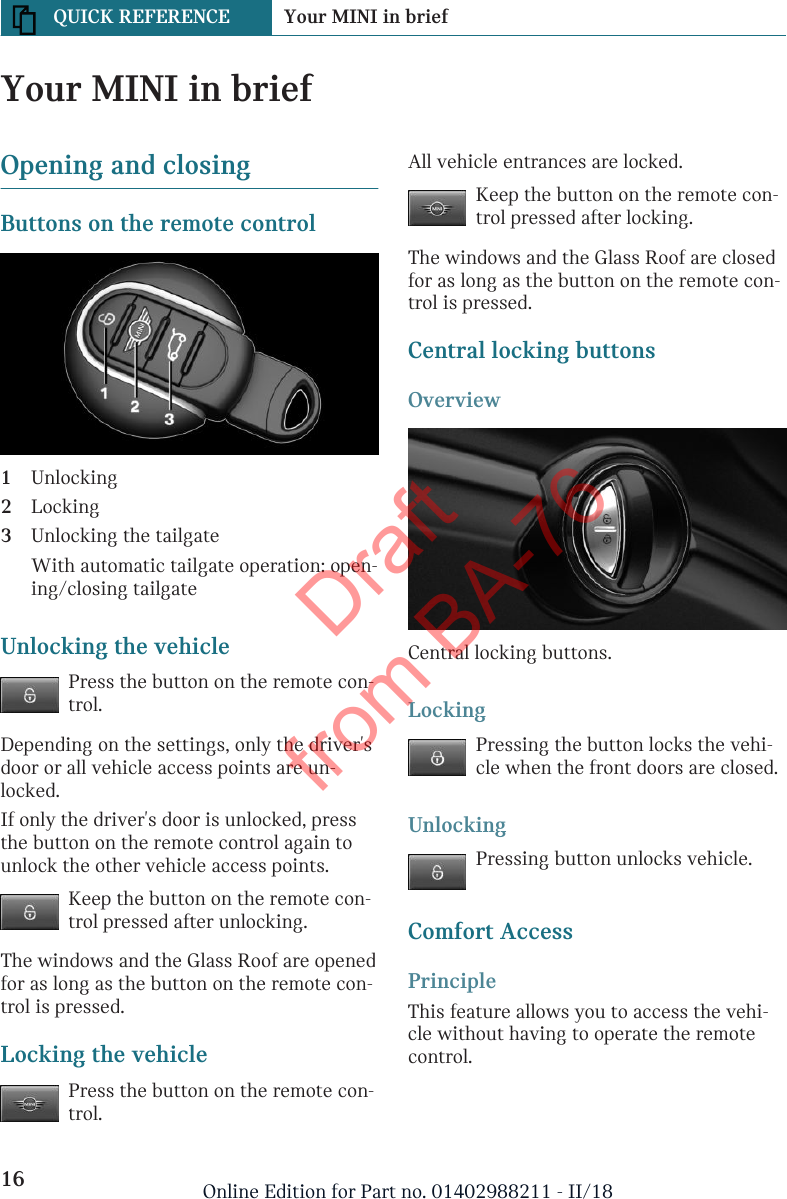
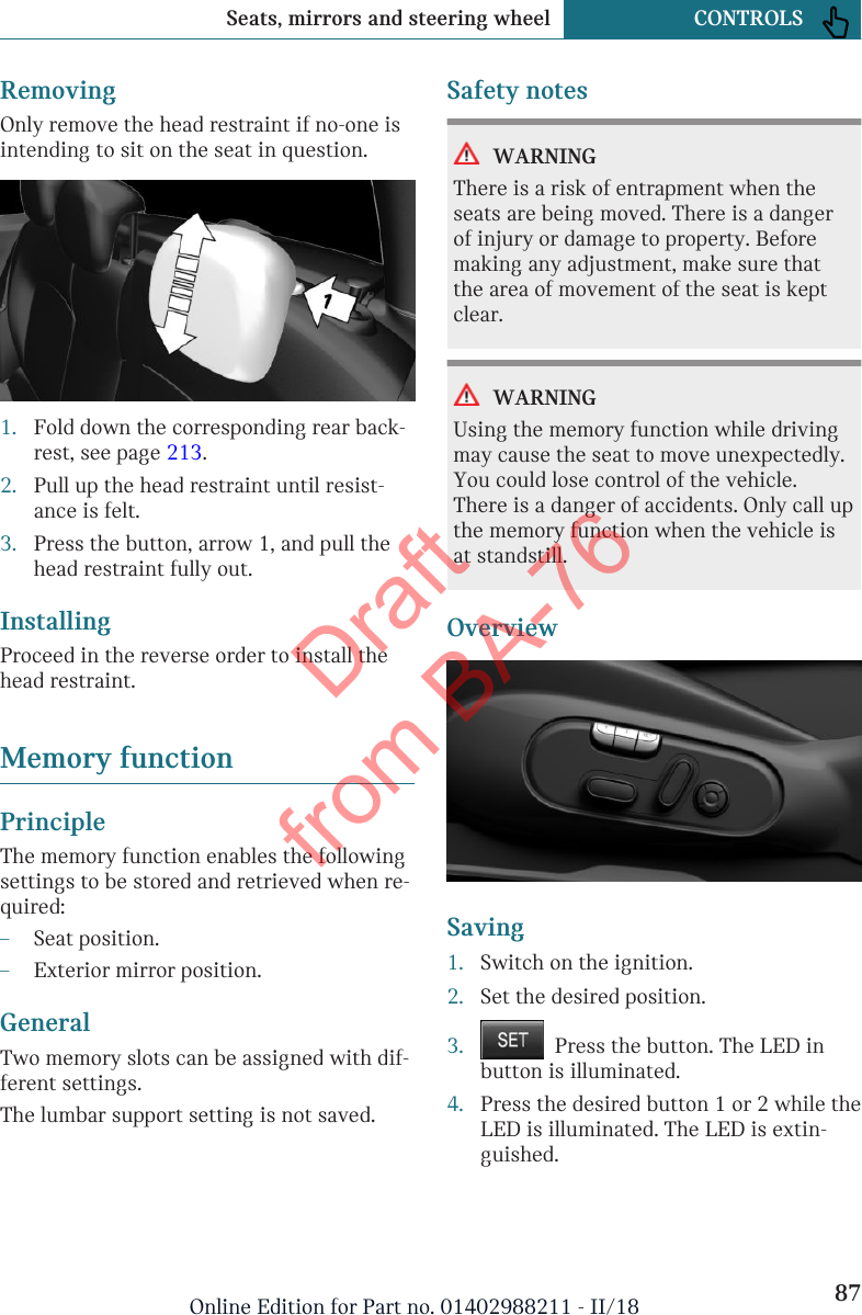
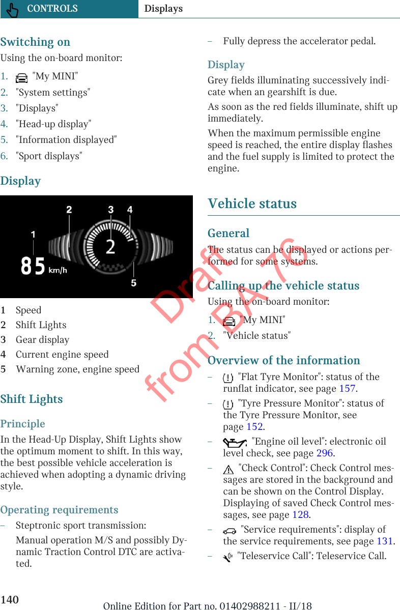
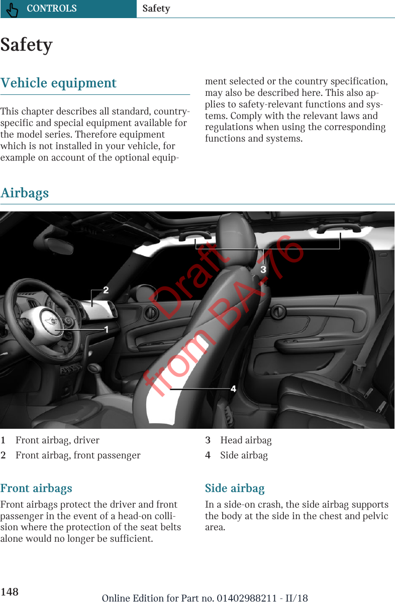
Alpine Electronics Inc Car Audio 05 Short Term Confidential 1
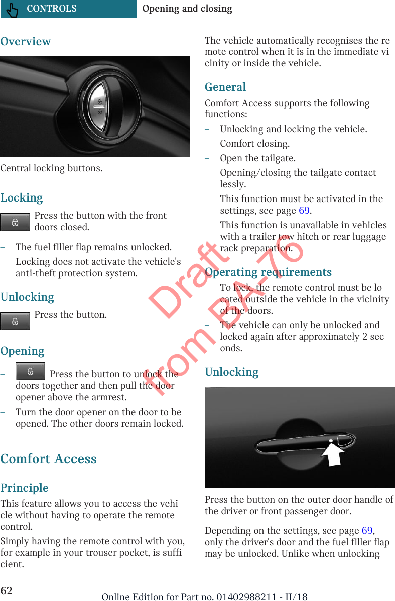
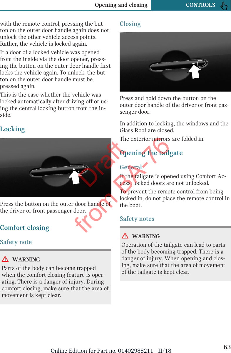
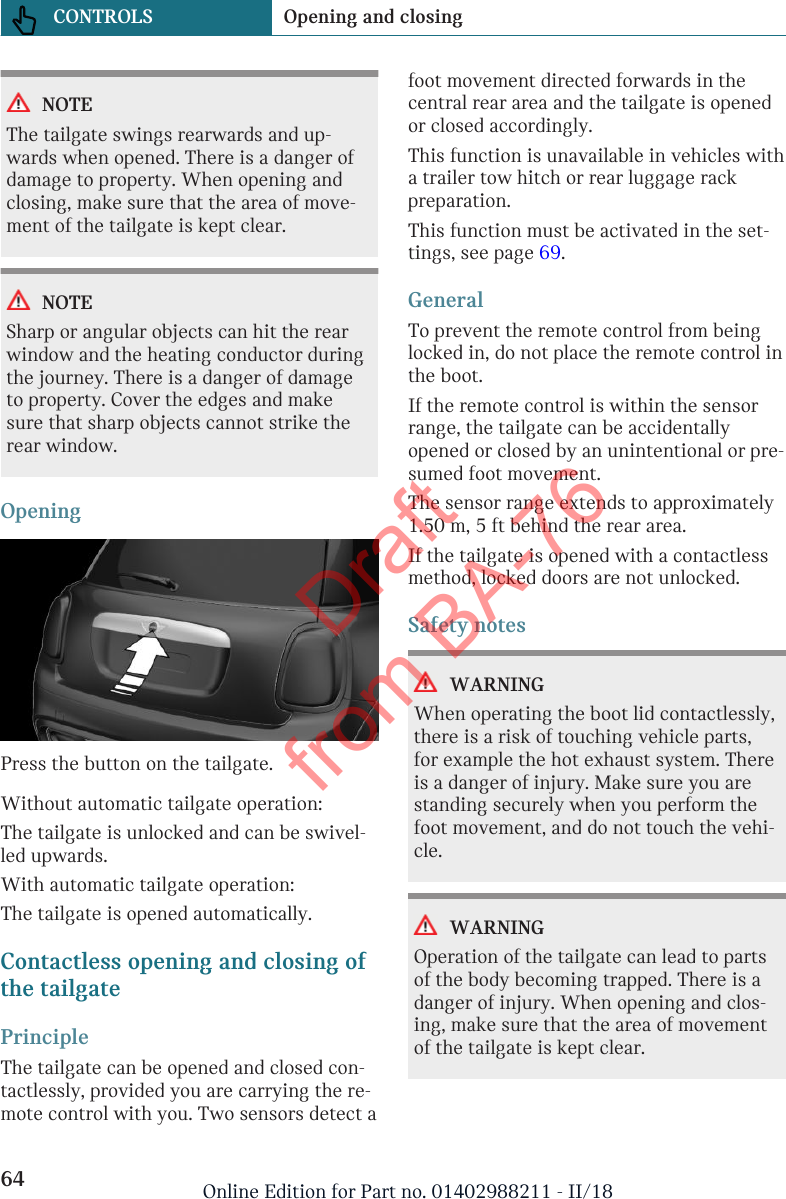
Contents

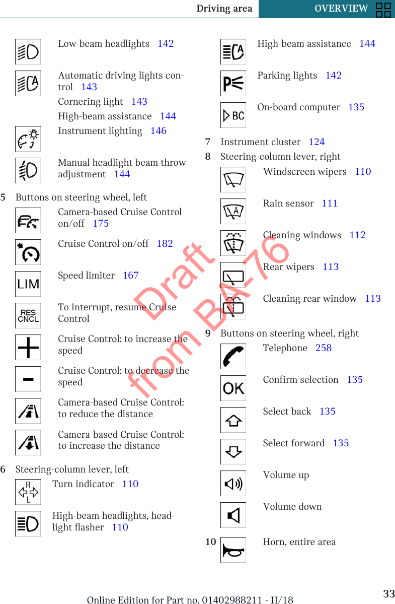
05 (Short-Term Confidential) User Manual_1

OWNER'S HANDBOOK.MINI COUNTRYMAN.LINK:CONTENT & A-ZOnline Edition for Part no. 01402988211 - II/18Draft from BA-76
Online Edition for Part no. 01402988211 - II/18Draft from BA-76
WELCOME TOMINI.OWNER'S HANDBOOK.MINI COUNTRYMAN.Congratulations on your choice of a MINI.The better you are acquainted with your vehicle, the easier you will find it isto operate. We would therefore like to offer you the following advice:Please read the Owner's Handbook before setting out in your new MINI. Itcontains important information on how to operate the vehicle, enabling you toderive maximum benefit from the technical advantages of your MINI. It alsocontains useful information which will help you to maintain both theoperating and road safety of your MINI as well as its full resale value.If applicable, you will find updates after the editorial deadline in the appendixof the printed Owner's Handbook for the vehicle.Start now. We wish you every enjoyment with your MINI.3Online Edition for Part no. 01402988211 - II/18Draft from BA-76
TABLE OF CONTENTSNOTESNotes.......................................................................................................................................... 8QUICK REFERENCEYour MINI in brief...............................................................................................................164Online Edition for Part no. 01402988211 - II/18Draft from BA-76
OVERVIEWDriving area...........................................................................................................................32On-board monitor................................................................................................................ 36General settings...................................................................................................................41Owner's Handbook media..................................................................................................50CONTROLSOpening and closing........................................................................................................... 56Seats, mirrors and steering wheel..................................................................................77Carrying children safely.....................................................................................................91Driving..................................................................................................................................102Displays................................................................................................................................124Lights....................................................................................................................................141Safety.....................................................................................................................................148Driving Stability Control Systems................................................................................170Driving comfort................................................................................................................. 175Air conditioning................................................................................................................ 195Interior equipment............................................................................................................204Storage compartments.....................................................................................................207Boot........................................................................................................................................210DRIVING HINTSDriving precautions..........................................................................................................220Towing a trailer or using rear luggage rack............................................................. 229Saving fuel...........................................................................................................................236For quick access to a particular topic or item, please consult thedetailed alphabetical index, see page 384.5Online Edition for Part no. 01402988211 - II/18Draft from BA-76
ENTERTAINMENTGeneral................................................................................................................................. 244Sound.....................................................................................................................................246Radio..................................................................................................................................... 248Audio.....................................................................................................................................252COMMUNICATIONTelephone............................................................................................................................ 258MINI Connected................................................................................................................ 262MOBILITYRefuelling............................................................................................................................ 268Fuel........................................................................................................................................270Wheels and tyres...............................................................................................................276Engine compartment........................................................................................................293Engine oil.............................................................................................................................296Coolant..................................................................................................................................300Maintenance....................................................................................................................... 302Replacing parts.................................................................................................................. 305Breakdown Assist..............................................................................................................316General care........................................................................................................................325REFERENCETechnical data.................................................................................................................... 332Appendix..............................................................................................................................344License Texts and Certifications..................................................................................345Everything from A to Z....................................................................................................384© 2018 Bayerische Motoren WerkeAktiengesellschaftMunich, GermanyNot to be reproduced, wholly or in part, without written permission from BMW AG, Munich.English ID5 II/18, 03 18 490Printed on environmentally friendly paper, bleached without chlorine, suitable for recycling.6Online Edition for Part no. 01402988211 - II/18Draft from BA-76
For quick access to a particular topic or item, please consult thedetailed alphabetical index, see page 384.7Online Edition for Part no. 01402988211 - II/18Draft from BA-76
NotesAbout this Owner's HandbookOrientationThe quickest way to find information on aparticular topic or feature is to consult thealphabetical index.We recommend that you read through thefirst chapter to obtain an initial overview ofthe vehicle.Updates after going to pressUpdates following the copy deadline can re-sult in differences between the printedOwner's Handbook and the following Own-er's Handbooks:–Online Owner's Handbook.–MINI Driver's Guide App.You will find notes on any updates in theappendix of the printed Owner's Handbookfor the vehicle.Additional sources of informa-tionService PartnerA Service Partner of the manufacturer willbe happy to answer any further questions.InternetOwner's Handbook and general informationon MINI, for example on technology, areavailable on the Internet: www.mini.comMINI Driver's Guide AppIn many countries, the Owner's Handbook isavailable as an app for IOS or Android fromthe corresponding store.Online Owner's HandbookThe Online Owner's Handbook specificallydescribes the equipment and functionspresent in the vehicle. The Online Owner'sHandbook can be displayed in any of today'sbrowsers. For further information, seepage 51.Symbols and displaysSymbols in the Owner's HandbookSym-bol Meaning  Precautions that must befollowed in order to avoid thepossibility of injury to yourselfand to others as well as seriousdamage to the vehicle.◄End of a specific item ofinformation.  Measures that can be taken tohelp protect the environment."..." Texts on the control display forselecting functions.ActionsThe actions to be carried out are shown as anumbered list. The sequence of steps mustbe followed.1. First action.2. Second action.Seite 8NOTES Notes8Online Edition for Part no. 01402988211 - II/18Draft from BA-76
ListsAlternative options and lists of items withno implied sequence are shown as bulletpoint lists:–First option.–Second option.Symbol on components andassemblies  This symbol on a vehicle componentindicates that further information on thecomponent is available in the Owner'sHandbook.Vehicle equipmentThis Owner's Handbook describes all mod-els and all the national and special equip-ment available for the model series. As a re-sult, this Owner's Handbook may alsocontain descriptions and illustrations ofequipment and functions not featured inyour vehicle, for example due to selectedspecial equipment or the country specifica-tion.This also applies to safety-relevant func-tions and systems.Comply with the relevant laws and regula-tions when using the corresponding func-tions and systems.If certain equipment and models are not de-scribed in this Owner's Handbook, refer tothe Supplementary Owner's Handbooks pro-vided.In right-hand drive vehicles, some controlsare arranged differently from those shownin the illustrations.Production dateThe production date of your vehicle can befound at the bottom of the door pillar on thedriver's door.The production date is defined as the calen-dar month and the calendar year in whichthe vehicle body and the powertrain assem-blies are joined and the vehicle is driven ormoved from the production line.Status of the Owner'sHandbookGeneralContinuous development ensures high lev-els of vehicle safety and quality. In rare in-stances, your vehicle may therefore differfrom the information supplied here.For Australia/New Zealand: generalWhen reading this Owner's Handbook,please bear the following in mind: to ensurethat our vehicles continue to embody thehighest quality and safety standards, wepursue a policy of continuous, ongoing de-velopment. Because modifications in the de-sign of both vehicles and accessories maybe introduced at any time, your own vehi-cle's equipment may vary from that descri-bed in this handbook. For the same reason,it is also impossible to guarantee that all de-scriptions will be completely accurate in allrespects.We must therefore request your under-standing of the fact that the manufacturerof your vehicle is unable to recognise legalclaims based on discrepancies between thedata, illustrations and descriptions in thisOwner's Handbook and your own vehicle'sequipment. Please note, too, that some ofthe optional equipment described in thisSeite 9Notes NOTES9Online Edition for Part no. 01402988211 - II/18Draft from BA-76
manual is not available on Australian mod-els due to restrictions imposed by Austral-ian Design Rules and other requirements.Should you require any further information,please contact your Service Partner or aqualified specialist workshop, who will bepleased to advise you.Updates after going to pressUpdates following the copy deadline can re-sult in differences between the printedOwner's Handbook and the following Own-er's Handbooks:–Online Owner's Handbook.–MINI Driver's Guide App.You will find notes on any updates in theappendix of the printed Owner's Handbookfor the vehicle.Your own safetyManufacturerThe manufacturer of this MINI is Bayeri-sche Motoren Werke Aktiengesellschaft,BMW AG.Intended useComply with the following when using thevehicle:–Owner's Handbook.–Information on the vehicle. Do not re-move stickers.–Technical data of the vehicle.–The applicable laws and safety standardsof the country in which the vehicle isused.–Vehicle papers and legal documents.WarrantyYour vehicle is technically designed for theoperating conditions and approval require-ments prevalent in the country to which itwas first delivered - homologation. If yourvehicle is to be operated in another country,it may have to be adapted to any prevailingdifferent operating conditions and approvalrequirements. If your vehicle does not com-ply with the homologation requirements ina certain country you cannot lodge warrantyclaims for your vehicle there. A ServicePartner is able to provide further informa-tion.Maintenance and repairsThe advanced technology used in your vehi-cle, for example the state-of-the-art materi-als and high-performance electronics, re-quires suitably appropriate maintenanceand repair methods.Consequently, the manufacturer of your ve-hicle recommends having correspondingwork carried out by a MINI Service Partner.If you choose to use another specialistworkshop, the manufacturer recommendsusing one that performs work such as main-tenance and repair according to MINI speci-fications with properly trained personnel. Inthis Owner's Handbook, facilities of thiskind are referred to as "another qualifiedservice centre or a specialist workshop".If such work, for example maintenance andrepair, is performed inexpertly, it could re-sult in consequential damage and thus con-stitute a safety risk.Parts and accessoriesMINI recommends using parts and acces-sory products that are specifically approvedfor this purpose by the manufacturer of theMINI.You are recommended to consult a MINIService Partner for advice on genuine MINISeite 10NOTES Notes10 Online Edition for Part no. 01402988211 - II/18Draft from BA-76
parts and accessories, other MINI manufac-turer approved products and expert adviceon all related matters.The safety and compatibility of these prod-ucts in conjunction with MINI vehicleshave been checked by the MINI manufac-turer.The MINI manufacturer accepts product re-sponsibility for genuine MINI parts and ac-cessories. On the other hand, the MINI man-ufacturer cannot accept liability for parts oraccessory products of any kind which it hasnot approved.The MINI manufacturer is unable to assesseach individual product of outside origin asto its suitability for use on MINI vehicleswithout safety risk. Nor can suitability beassured if an official permit has been issuedfor it in a specific country. Tests performedfor such permits cannot always cover all op-erating conditions for MINI vehicles, andsome of them therefore are insufficient.Data memoryGeneralA number of electronic control devices areinstalled in your vehicle. Some of these arenecessary for the vehicle to function safelyor provide assistance during driving, for ex-ample Driver Assistance Systems. There arealso control devices which manage comfortor infotainment functions.Electronic control devices contain datamemories, which can temporarily or perma-nently store information about the vehicle'scondition, component use and wear, mainte-nance requirements, technical events andfaults.This information generally documents thecondition of a component, a module, a sys-tem or its environment, for example:–Operating states of system components,for example, fill levels, tyre inflationpressure, battery status.–Status messages of the vehicle and itsindividual components, for examplewheel rotation speed, wheel speed, de-celeration, lateral acceleration, fastenedseat belt indicator.–Malfunctions and faults of importantsystem components, for example, lightsand brakes.–Information on vehicle-damagingevents.–Responses of the vehicle to particulardriving situations, for example, trigger-ing of an airbag, activation of the stabil-ity control systems.–Ambient conditions, for example tem-perature, rain sensor signals.The data is required to perform the controldevice functions. It is also used for detect-ing and rectifying malfunctions, and helpsthe vehicle manufacturer to optimise vehi-cle functions. The majority of this data istransient and is only processed within thevehicle itself. Only a small proportion of thedata is stored in event or error memoriesand, if necessary, in the vehicle key.Reading out dataWhen service work is being carried out,for example repairs, service operations, war-ranty work and quality assurance measures,this technical information can be read outfrom the vehicle together with the vehicleidentification number. A Service Partner ofthe manufacturer or another qualified Serv-ice Partner or a specialist workshop canread out the information. The legally re-quired on-board diagnostics (OBD) socket inthe vehicle is used to read out the data. Thedata is collected, processed and used by therelevant organisations in the service net-work. The data documents the technicalSeite 11Notes NOTES11Online Edition for Part no. 01402988211 - II/18Draft from BA-76
conditions of the vehicle, helps in locatingfaults and improving quality, and is trans-ferred to the vehicle manufacturer, if neces-sary.Furthermore, the manufacturer has productmonitoring obligations to meet in line withproduct liability law. To fulfil these obliga-tions, the vehicle manufacturer requirestechnical data from the vehicle. Error andevent memories in the vehicle can be resetwhen a Service Partner of the manufactureror another qualified Service Partner or aspecialist workshop performs repair or serv-icing work.Data on service work carried out and proofof maintenance is saved in the vehicle un-der the service history and transferred tothe vehicle manufacturer. The vehicleowner can contact a Service Partner of themanufacturer to object to the data beingsaved and transferred to the vehicle manu-facturer. This objection applies for as longas the vehicle owner remains the proprietorof the vehicle.Data entry and data transfer intothe vehicleGeneralDepending on the equipment, some data canbe transferred into the vehicle when usingcomfort and infotainment functions, for ex-ample:–Multimedia data such as music or filmsfor playback in an integrated multimediasystem.–Address book data for use in conjunc-tion with an integrated hands-free sys-tem or an integrated navigation system.–Entered navigation destinations.–Data on the use of Internet services.This data may be saved locally in the vehi-cle or is found on a device that has beenconnected to the vehicle, for example asmartphone, USB stick or MP3 player. If thisdata is saved in the vehicle, it can be de-leted at any time. This data is only transmit-ted to third parties if expressly desired. Thisdepends on the personal settings selectedfor using online services.Depending on the equipment, the followingcomfort and individual settings can besaved in the vehicle and modified at anytime, for example:–Settings for the seat and steering wheelpositions.–Suspension and climate control settings.–Individual settings, for example interiorlighting.Control via mobile end user devicesDepending on the equipment, mobile devi-ces connected to the vehicle, for examplesmartphones, can be controlled via the vehi-cle controls. Sound and images from the mo-bile end user device can be played back anddisplayed through the multimedia system.Certain information is transferred to themobile device at the same time. Dependingon the type of connection, this includes,for example position data and other generalvehicle information. This optimises the wayin which selected apps, for example naviga-tion or music playback, work.There is no further interaction between themobile device and the vehicle, for exampleactive access to vehicle data. How the datais processed further is determined by theprovider of the particular app being used.The range of settings depends on the re-spective app and the operating system ofthe mobile device.ServicesGeneralIf the vehicle has a wireless network con-nection, this enables data to be exchangedSeite 12NOTES Notes12 Online Edition for Part no. 01402988211 - II/18Draft from BA-76
between the vehicle and other systems. Thewireless network connection is establishedvia an in-vehicle transmitter and receiverunit or via personal mobile devices broughtinto the vehicle, for example smartphones.This wireless network connection enables"online functions" to be used, depending onthe equipment installed. These include on-line services and apps supplied by the vehi-cle manufacturer or by other providers.Services from the vehiclemanufacturerWhere online services from the vehiclemanufacturer are concerned, the relevantfunctions are described in the appropriateplace, for example the Owner's Handbook ormanufacturer's website. The relevant legalinformation pertaining to data protection isalso provided. Personal data may be used toperform online services. Data is exchangedover a secure connection, for example withthe IT systems of the vehicle manufacturerintended for this purpose. Any collection,processing and use of personal data aboveand beyond that needed to provide the serv-ices must always be based on legal permis-sion, a contractual arrangement or consent.In addition, the vehicle manufacturer evalu-ates anonymised information on transportinfrastructure and how the infotainmentsystem is used. This information cannot betraced back to individual vehicles or people.Evaluating the data enables the manufac-turer to further improve its products orservices, for example by incorporating themost up-to-date traffic information. Thedata transfer feature can be deactivated inthe vehicle. Certain services and functions,some of which are subject to a charge, canbe deactivated by the driver. It is also possi-ble to activate or deactivate the data con-nection as a whole. Excluded from this arefunctions and services which are requiredby law, for example emergency call systems.Services from other providersWhen using online services from other pro-viders, these services are the responsibilityof the relevant provider and subject to theirdata privacy conditions and terms of use.The vehicle manufacturer has no controlover the content exchanged when usingthese services. Information on the way inwhich personal data is collected and used inrelation to services from third parties, thescope of such data and its purpose, can beobtained from the relevant service provider.Vehicle identification numberThe vehicle identification number is in theengine compartment, on the right-hand sideof the vehicle.The vehicle identification number is on thetype plate, on the right-hand side of the ve-hicle.Seite 13Notes NOTES13Online Edition for Part no. 01402988211 - II/18Draft from BA-76
14 Online Edition for Part no. 01402988211 - II/18Draft from BA-76
  QUICK REFERENCEYour MINI in brief ................................................................................... 1615Online Edition for Part no. 01402988211 - II/18Draft from BA-76
Your MINI in briefOpening and closingButtons on the remote control1Unlocking2Locking3Unlocking the tailgateWith automatic tailgate operation: open-ing/closing tailgateUnlocking the vehiclePress the button on the remote con-trol.Depending on the settings, only the driver'sdoor or all vehicle access points are un-locked.If only the driver's door is unlocked, pressthe button on the remote control again tounlock the other vehicle access points.Keep the button on the remote con-trol pressed after unlocking.The windows and the Glass Roof are openedfor as long as the button on the remote con-trol is pressed.Locking the vehiclePress the button on the remote con-trol.All vehicle entrances are locked.Keep the button on the remote con-trol pressed after locking.The windows and the Glass Roof are closedfor as long as the button on the remote con-trol is pressed.Central locking buttonsOverviewCentral locking buttons.LockingPressing the button locks the vehi-cle when the front doors are closed.UnlockingPressing button unlocks vehicle.Comfort AccessPrincipleThis feature allows you to access the vehi-cle without having to operate the remotecontrol.Seite 16QUICK REFERENCE Your MINI in brief16 Online Edition for Part no. 01402988211 - II/18Draft from BA-76
Simply having the remote control with you,for example in your trouser pocket, is suffi-cient.The vehicle automatically recognises the re-mote control when it is in the immediate vi-cinity or inside the vehicle.Unlocking the vehiclePress the button on the door handle of thedriver or front passenger door.Locking the vehiclePress the button on the door handle of thedriver or front passenger door.TailgateOpeningUnlock the vehicle and press the button onthe tailgate.–Unlock the vehicle and press the buttonon the tailgate.–If you are carrying the remote control,press the button on the tailgate.–Press and hold the button on theremote control for approxi-mately 1 second.If applicable, the doors are also un-locked.ClosingPress the button on the inside of the tail-gate.Seite 17Your MINI in brief QUICK REFERENCE17Online Edition for Part no. 01402988211 - II/18Draft from BA-76
–Press the button on the inside of thetailgate, arrow 1.–Press the button, arrow 2.The vehicle is locked after the tailgatehas been closed. To do this, the driver'sdoor must be closed and the remote con-trol must be outside the vehicle in thevicinity of the tailgate.–Keep the button on the remotecontrol pressed until the tailgatehas closed.Seats, mirrors and steeringwheelManually adjustable seats1Forward/back2Thigh support3Height4Backrest angleElectrically adjustable seats1Memory function2Lumbar support3Backrest angle4Forward/back, height, seat angleTo adjust the head restraintHeight–Upwards: push head restraint upwards.–Downwards: press the button, arrow 1,and slide the head restraint downwards.Seite 18QUICK REFERENCE Your MINI in brief18 Online Edition for Part no. 01402988211 - II/18Draft from BA-76
To adjust the exterior mirrors1To adjust2To select a mirror, automatic parkingfunction3To fold in and outTo adjust the steering wheelIn four directions1. Switch on the ignition.2. Fold the lever downwards.3. Move the steering wheel to the prefer-red height and angle to suit your seatedposition.4. Swing the lever back up.5. Switch off the ignition again if neces-sary.Memory functionPrincipleThe memory function enables the followingsettings to be stored and retrieved when re-quired:–Seat position.–Exterior mirror position.Saving1. Switch on the ignition.2. Set the desired position.3.   Press the button. The LED inbutton is illuminated.4. Press the desired button 1 or 2 on theseat while the LED is illuminated. TheLED is extinguished.RecallingThe saved position is called up automati-cally.Press the desired button 1 or 2.The operation is halted when you press aseat adjustment switch or one of the mem-ory buttons.Adjusting the seat position on the driver'sside is interrupted after a short time duringthe journey.Seite 19Your MINI in brief QUICK REFERENCE19Online Edition for Part no. 01402988211 - II/18Draft from BA-76
Displays and controlsAround the steering wheel1Low-beam headlights, fog light2High-beam headlights, flasher, indicator3Instrument cluster4Wiper systemIndicator and warning lampsInstrument clusterIndicator and warning lamps can illuminatein a variety of combinations and colours.When the engine starts or the ignition isswitched on, the functionality of somelights is checked and they illuminate briefly.Driver's door1Safety switch2Power window switches3Exterior mirrorsAround the selector lever1Selector lever2Controller with buttons3Parking brakeOn-board monitorPrincipleThe on-board monitor brings together thefunctions of a number of switches. Thesefunctions can be operated using the Con-troller.ControllerGeneralThe buttons can be used to call up menusdirectly. The Controller can be used to se-lect menu items and perform settings.Buttons on the ControllerButton FunctionPress once: to call up the mainmenu.Press twice: to call up the lastused menus.To call up the previous screen.To call up the Options menu.Seite 20QUICK REFERENCE Your MINI in brief20 Online Edition for Part no. 01402988211 - II/18Draft from BA-76
Button FunctionCall up the Audio menu.To call up the Telephone menu.DrivingStarting and stopping the engineIgnition on/off–On: press the start/stopbutton.Most of the indicator andwarning lamps are illumi-nated for different lengthsof time.–Off: press the start/stop button again.All indicator lamps turn off.–Radio ready state: with the ignitionswitched off, press on the on/off buttonon the radio or press the start/stop but-ton when the engine is running.Individual power consumers remain op-erational.Starting/stopping engineSteptronic transmission: starting1. Depress the brake pedal.2. Engaging the selector lever in position Por N.3. Press the start/stop button.Manual gearbox: starting1. Depress the brake pedal.2. Press the clutch and engage idle posi-tion.3. Press the start/stop button.Steptronic transmission: stopping1. Apply the parking brake when the vehi-cle is stationary.2. Engaging the selector lever in posi-tion P.3. Press the start/stop button.Manual gearbox: stopping1. Press the Start/Stop button when thevehicle is at standstill.2. Engage first gear or reverse.3. Apply the parking brake.Auto Start Stop functionSteptronic transmission: switches the en-gine off automatically at a standstill to savefuel. As soon as the brake pedal is released,the engine starts automatically.Manual gearbox: switches the engine off au-tomatically at a standstill to save fuel. Assoon as the clutch pedal is released, the en-gine starts automatically.Parking brakeEngagingPull the switch.LED and indicator lamp are illumina-ted.ReleasingManual transmission: press the buttonwith the brake pedal depressed.Steptronic transmission: press the switchwith the brake pedal depressed or selectorlever position P engaged.LED and indicator lamp turn off.The parking brake is released.Seite 21Your MINI in brief QUICK REFERENCE21Online Edition for Part no. 01402988211 - II/18Draft from BA-76
Manual gearboxShifting gearsDuring the shifting process into 5th/6thgear level, push the gear shift lever to theright, otherwise, to avoid inadvertentswitching to the 3rd or 4th gear.Reverse gearEngage this position only when the vehicleis stationary.To overcome the resistance, move the shiftlever firmly to the left towards the left andengage the reverse gear with a gear shiftmovement forwards.Steptronic transmissionSelector lever positionsP Park position.R reverse.N neutral.D drive position.Only engage selector lever position P or Rwhen the vehicle is stationary.Apply the brakes until ready to drive off,otherwise the vehicle will move when adrive position or reverse gear is selected.Selector lever lockA lock prevents an inadvertent change fromselector lever position P to another selectorlever position and, depending on the trans-mission version, inadvertent shifting fromselector lever position P or R.To cancel the lock: with the brake pedalpressed, press the button on the front orside of the selector lever.Steptronic transmission, Sport andmanual operationSport programme:Press the selector lever out of selector leverposition D to the left.Manual operation:–To shift down: press the selector leverforwards.–To shift up: pull the selector lever back-wards.High-beam headlights, headlightflasher, turn indicators, parkinglightsHigh-beam headlights, headlightflasherPush the lever forwards or pull it back.–High-beam headlights, arrow 1.–Headlight flasher, arrow 2.Seite 22QUICK REFERENCE Your MINI in brief22 Online Edition for Part no. 01402988211 - II/18Draft from BA-76
Turn indicator–On: press the lever beyond the resist-ance point.–Off: lightly tip the lever as far as the re-sistance point.–Triple turn signal: lightly tip the lever upor down.–Indicating a turn briefly: press the leveras far as the resistance point and hold itthere for as long as you wish to indicatea turn.Parking lightIlluminate the vehicle on one side.–On: with the ignition switched off, pushthe lever upwards or downwards beyondthe resistance point for approximately2 seconds.–Off: press the lever briefly in the oppo-site direction as far as the resistancepoint.Light and lightingLight functionsSymbol FunctionRear fog lights.Front fog lights.Automatic driving lights control.Lights off.Automatic driving lights control.Daytime driving lights.Side lights.Low-beam headlights.Manual headlight beam throwadjustment.Instrument lighting.Seite 23Your MINI in brief QUICK REFERENCE23Online Edition for Part no. 01402988211 - II/18Draft from BA-76
Wiper systemSwitching the wipers on/off and flick-wipingSwitching onTap the lever up or push it beyond the re-sistance point.–Normal wiping speed: press upwardsonce.–Rapid wiping speed: press upwardstwice or press once beyond the resist-ance point.Switching off and flick-wipingPress the lever down.–Switching off fast mode: press down-wards twice.–Switching off normal mode: press down-wards once.–To flick-wipe: press downwards once.Rain sensorActivating/deactivatingPress the button on the wiper lever.Adjust sensitivity:Turn the knurled wheel on the wiper lever.To clean the windscreenPull the lever.Seite 24QUICK REFERENCE Your MINI in brief24 Online Edition for Part no. 01402988211 - II/18Draft from BA-76
Air conditioningAir conditioning systemButton FunctionTemperature.Cooling function.Recirculated-air mode.Adjust the air flow man-ually.Adjust the air distributionmanually.Windscreen heating.Automatic air conditioningButton FunctionTemperature.Cooling function.Maximum cooling.AUTO program.Button FunctionRecirculated-air mode.Automatic air recirculationcontrol AUC/recirculated-air mode.Adjust the air flow man-ually.Air distribution, manual.Defrost and demist the win-dows.Windscreen heating.Rear window heating.InfotainmentRadioControls1Traffic information2Changing the entertainment source3Sound output on/off, volumeSeite 25Your MINI in brief QUICK REFERENCE25Online Edition for Part no. 01402988211 - II/18Draft from BA-76
4Changing station/track5Favourites buttonsMobile telephone registerOnce the mobile telephone has been con-nected in the vehicle, it can be operated us-ing the on-board monitor, the buttons onthe steering wheel and by voice control.1. "My MINI"2. "System settings"3. "Mobile devices"4. "Connect new device"The Bluetooth name of the vehicle isdisplayed in the Control Display.5. To perform other operations on the mo-bile telephone; see the user manual ofthe mobile telephone: for example find-ing/connecting Bluetooth device or newdevice.The Bluetooth name of the vehicle isshown on the display of the mobile tele-phone. Select the Bluetooth name of thevehicle.6. Depending on the mobile device, eithera control number is displayed, or youwill have to enter the control numberyourself.–Compare the control number shownon the Control Display with the con-trol number in the device display.Confirm the control number in thedevice and on the Control Display.–Enter the same control number onthe device and via the on-board mon-itor then confirm.The device is connected and displayedin the device list.The mobile telephone is connected andshown in the first position on the list of mo-bile telephones.TelephonyAccepting a callIncoming calls can be accepted using theon-board monitor or using the button on thesteering wheel.Using the on-board monitor  "Accept"Via button on the steering wheelPress the button.Dialling a number1. "Communication"2. "Dial number"3. Select the numbers individually.4.   Select the symbol.Refuelling stopRefuellingFuel tank cap1. Tap the rear edge of the fuel filler flap toopen it.2. Turn the fuel tank cap anticlockwise.3. Place the fuel tank cap in the holder onthe fuel filler flap.PetrolFor optimal fuel consumption, the petrolshould be sulphur-free or low in sulphurcontent.Only refuel with unleaded petrol withoutmetallic additives.Information about the recommended petrolgrade is provided in the Owner's Handbook.Seite 26QUICK REFERENCE Your MINI in brief26 Online Edition for Part no. 01402988211 - II/18Draft from BA-76
DieselDiesel fuel to DIN EN 590 standard.Wheels and tyresTyre inflation pressure informationThe tyre inflation pressures are on the plateon the door pillar.Checking the tyre inflation pressureCheck regularly and adjust as necessary:–At least twice a month.–Before a long journey.After adjusting the tyre inflationpressureReinitialise runflat indicator.Reset the Tyre Pressure Monitor.Electronic oil measurementRequirementsA current measurement is available afterapproximately 30 minutes of the journey.With a shorter journey, the status of thelast sufficiently long journey is shown.In the detailed measurement in addition:–Vehicle is on a level street and with theengine at operating temperature.–Manual gearbox:Gear lever in idling position, clutch andaccelerator pedal not applied.–Steptronic transmission:Selector lever in selector lever positionN or P and accelerator pedal not applied.Displaying the engine oil levelOn the radio:1.   Press the button.2.   "Vehicle information"3. "Vehicle status"4. "Engine oil level"The engine oil level is displayed.Adding engine oilGeneralSwitch off the ignition and safely park thevehicle before topping up with engine oil.Topping upDo not top up engine oil unless a message isdisplayed in the instrument cluster.Note the top-up quantity in the message.Ensure not to top up with too much engineoil.Note recommended engine oil types.Seite 27Your MINI in brief QUICK REFERENCE27Online Edition for Part no. 01402988211 - II/18Draft from BA-76
Breakdown AssistHazard warning lightsThe button is situated above the ControlDisplay.Breakdown AssistMobile ServiceAvailable by phone twenty-four hours a day,seven days a week in many countries.Breakdown assistance1.   "Services"2. "Mobile Care"3. "Start service"Contact to the mobile service is resaved.A telephone number may be displayed.Select it to dial the telephone numberusing a connected mobile telephone.Warning triangle, first-aid kitFirst-aid kitThe first-aid kit is in the boot.Warning triangleThe warning triangle is located in the tail-gate. To remove, release the mounts.Seite 28QUICK REFERENCE Your MINI in brief28 Online Edition for Part no. 01402988211 - II/18Draft from BA-76
Seite 29Your MINI in brief QUICK REFERENCE29Online Edition for Part no. 01402988211 - II/18Draft from BA-76
30 Online Edition for Part no. 01402988211 - II/18Draft from BA-76
  OVERVIEWDriving area ............................................................................................... 32On-board monitor ..................................................................................... 36General settings .......................................................................................  41Owner's Handbook media ...................................................................... 5031Online Edition for Part no. 01402988211 - II/18Draft from BA-76
Driving areaVehicle equipmentThis chapter describes all standard, country-specific and special equipment available forthe model series. Therefore equipmentwhich is not installed in your vehicle, forexample on account of the optional equip-ment selected or the country specification,may also be described here. This also ap-plies to safety-relevant functions and sys-tems. Comply with the relevant laws andregulations when using the correspondingfunctions and systems.Around the steering wheel1Power window switches   722Exterior mirror operation   883Buttons of the central locking   614LightsFront fog lights   145Rear fog lights   145Light switch   141Lights offAutomatic driving lights con-trol   143Daytime driving lights   143Side lights   141Seite 32OVERVIEW Driving area32 Online Edition for Part no. 01402988211 - II/18Draft from BA-76
Low-beam headlights   142Automatic driving lights con-trol   143Cornering light   143High-beam assistance   144Instrument lighting   146Manual headlight beam throwadjustment   1445Buttons on steering wheel, leftCamera-based Cruise Controlon/off   175Cruise Control on/off   182Speed limiter   167To interrupt, resume CruiseControlCruise Control: to increase thespeedCruise Control: to decrease thespeedCamera-based Cruise Control:to reduce the distanceCamera-based Cruise Control:to increase the distance6Steering-column lever, leftTurn indicator   110High-beam headlights, head-light flasher   110High-beam assistance   144Parking lights   142On-board computer   1357Instrument cluster   1248Steering-column lever, rightWindscreen wipers   110Rain sensor   111Cleaning windows   112Rear wipers   113Cleaning rear window   1139Buttons on steering wheel, rightTelephone   258Confirm selection   135Select back   135Select forward   135Volume upVolume down10 Horn, entire areaSeite 33Driving area OVERVIEW33Online Edition for Part no. 01402988211 - II/18Draft from BA-76
11 To adjust the steering wheel   9012 To release the bonnet   29413 With automatic tailgate operation: oper-ate the tailgate   65Around the centre console1Hazard warning lights   316Intelligent Safety   1592Control Display   363Radio/Multimedia4Glove box   2075Climate   1956Park Distance Control,PDC   184Rear-view camera   187Park Assistant   190Auto Start Stop function   105Engine start/stop and ignitionon/off   102Dynamic Stability Control,DSC   170MINI Driving Modesswitch   172Seite 34OVERVIEW Driving area34 Online Edition for Part no. 01402988211 - II/18Draft from BA-76
7Steptronic transmission selectorlever   116 Manual transmission selectorlever   1158Controller with buttons   379Parking brake   108Around the roof lining1Emergency call, SOS   3162Front passenger airbag indica-tor lamp   1513Reading lights   1474Ambient lighting   1475Panorama Glass Roof   746Interior light   146Seite 35Driving area OVERVIEW35Online Edition for Part no. 01402988211 - II/18Draft from BA-76
On-board monitorVehicle equipmentThis chapter describes all standard, country-specific and special equipment available forthe model series. Therefore equipmentwhich is not installed in your vehicle, forexample on account of the optional equip-ment selected or the country specification,may also be described here. This also ap-plies to safety-relevant functions and sys-tems. Comply with the relevant laws andregulations when using the correspondingfunctions and systems.PrincipleThe on-board monitor brings together thefunctions of a number of switches. Thesefunctions can be operated using the Con-troller.Safety noteWARNINGOperating integrated informations systemsand communication devices during thejourney may distract you from the traffic.You could lose control of the vehicle.There is a danger of accidents. Only oper-ate the systems or devices if permissiblein the traffic situation. Stop if necessaryand operate the systems or devices withthe vehicle at a standstill.ControlsOverview1Control Display2Controller with buttonsControl DisplayGeneralTo clean the Control Display, comply withthe information regarding care, seepage 329.If the Control Display is exposed to veryhigh temperatures, for example because ofstrong sunlight, there may be a reduction inbrightness and the Control Display mayeven switch itself off. Normal functions willbe restored when the temperature is re-duced, for example by shading or using theair conditioning system.Safety noteNOTEObjects located in front of the Control Dis-play may slip and damage the Control Dis-play. There is a danger of damage to prop-erty. Do not place objects in front of theControl Display.Seite 36OVERVIEW On-board monitor36 Online Edition for Part no. 01402988211 - II/18Draft from BA-76
Switching on/off automaticallyThe Control Display is switched on automat-ically after unlocking.In certain situations, the Control Display isswitched off automatically, for example if nooperation is performed on the vehicle forseveral minutes.Switching on/off manuallyThe Control Display can also be switched offmanually.1.   Press the button.2. "Switch off control display"Press the Controller or any button on theController to switch it back on again.ControllerGeneralThe buttons can be used to call up menusdirectly. The Controller can be used to se-lect menu items and perform settings.Operation–Turning.–Pressing.–Tilting in two directions.Buttons on the ControllerButton FunctionPress once: to call up the mainmenu.Press twice: to call up the lastused menus.To call up the previous screen.To call up the Options menu.Call up the Audio menu.To call up the Telephone menu.Seite 37On-board monitor OVERVIEW37Online Edition for Part no. 01402988211 - II/18Draft from BA-76
Operation using the ControllerCalling up the main menuPress the button.The main menu is displayed.All on-board monitor functions can be calledup via the main menu.Selecting a menu itemHighlighted menu items can be selected.1. Turn the Controller until the desiredmenu item is highlighted.2. Press the Controller.Menu items in the Owner'sHandbookIn this Owner's Handbook, the menu itemsthat are to be selected are shown in quota-tion marks, for example "System settings".Switching between screensAfter a menu item has been selected, for ex-ample "System settings", a new screen isdisplayed.–Tilt the Controller to the left.The current screen is closed and theprevious screen is displayed.–  Press the button.The previous screen is opened again.–Tilt the Controller to the right.The new screen is opened.An arrow indicates that further screens canbe called up.Calling up recently used menusThe recently used menus can be displayed.Press the button twice.Calling up the Options menuPress the button.The "Options" menu is displayed.The Options menu consists of various areas:–Operating options for the selected mainmenu, for example for "Media/Radio".–If applicable, other operating options forthe selected menu, for example "Savestation".To adjust the settings1. Select a field.2. Turn the Controller until the desired set-ting is displayed.3. Press the Controller.Enabling/disablingfunctionsSome menu items are preceded by a check-box. This indicates whether the function isSeite 38OVERVIEW On-board monitor38 Online Edition for Part no. 01402988211 - II/18Draft from BA-76
enabled or disabled. Selecting the menuitem enables or disables the function.  Function is enabled.  Function is disabled.Entering letters and numbersGeneralLetters and numbers can be entered via theController.The keyboard display changes automati-cally.Entry1. Turn the Controller: to select letters ornumbers.2.   : to confirm your entry.Symbol Function  Press Controller: to deleteletters or numbers.  or  Press and hold the Controller:to delete all letters or num-bers.Changing between upper/lower case,numbers and charactersDepending on the menu, upper and lowercase letters as well as numbers and symbolscan be entered:Without navigation system            Select the symbol.Entry comparisonWhen entering names and addresses, theselection is gradually narrowed down andpossibly supplemented with every subse-quent letter that you enter.Inputs are continuously compared with thedata saved in the vehicle.Only letters for which data is available areoffered for entry.Operating alphabetical listsFor alphabetic lists with more than 30 en-tries, the letters for which entries are avail-able can be shown on the left side.1. Turn the Controller quickly to the left orright.All the letters for which an entry isavailable are shown on the left-handside.2. Select the initial letter of the desired en-try.The first entry of the selected letter isdisplayed.Status informationGeneralThe status field is located in the top area ofthe Control Display. Status information isdisplayed in the form of symbols.Symbols in the status fieldTelephoneSymbol Meaning  Incoming or outgoing call.  Missed call.  Reception level of mobile tele-phone network.Symbol flashes: searching fornetwork.  No mobile telephone networkavailable.  Data transfer not possible.Seite 39On-board monitor OVERVIEW39Online Edition for Part no. 01402988211 - II/18Draft from BA-76
Symbol Meaning  Roaming active.  Text message received.  Message received.  Reminder.  Sending not possible.EntertainmentSymbol Meaning  Bluetooth audio.  USB audio interface.Other functionsSymbol Meaning  Check Control message.  Sound output switched off.  Determining the current vehicleposition.  Traffic information.Favourites buttonsGeneralOn-board monitor functions, for exampleradio stations, telephone numbers andshortcuts to the menu, can be saved to Fa-vourites buttons and called up directly.The settings are saved for the currentlyused driver profile.Saving a function1. Select the function using the on-boardmonitor.2.   Press and hold the desired but-ton until a signal sounds.Performing a functionPress the button.The function is carried out immedi-ately. If you have selected a telephone num-ber, for example, the connection will also beestablished.Displaying the button assignmentTouch the buttons with your finger. Do notwear gloves or use objects.The button assignment is displayed at thetop edge of the screen.Clearing the button assignment1. Press and hold buttons 1 and 6 simulta-neously for approximately 5 seconds.2. "OK"Seite 40OVERVIEW On-board monitor40 Online Edition for Part no. 01402988211 - II/18Draft from BA-76
General settingsVehicle equipmentThis chapter describes all standard, country-specific and special equipment available forthe model series. Therefore equipmentwhich is not installed in your vehicle, forexample on account of the optional equip-ment selected or the country specification,may also be described here. This also ap-plies to safety-relevant functions and sys-tems. Comply with the relevant laws andregulations when using the correspondingfunctions and systems.LanguageTo set the languageUsing the on-board monitor:1.   "My MINI"2. "System settings"3. "Language"4. "Language:"5. Select the desired setting.The setting is saved for the currently useddriver profile.TimeSetting the timeUsing the on-board monitor:1.   "My MINI"2. "System settings"3. "Date and time"4. "Time:"5. Turn the Controller until the desiredhours are displayed.6. Press the Controller.7. Turn the Controller until the desired mi-nutes are displayed.8. Press the Controller.Setting the time formatUsing the on-board monitor:1.   "My MINI"2. "System settings"3. "Date and time"4. "Time format:"5. Select the desired setting.The setting is saved for the currently useddriver profile.DateSetting the dateUsing the on-board monitor:1.   "My MINI"2. "System settings"3. "Date and time"4. "Date:"5. Turn the Controller until the desired dayis displayed.6. Press the Controller.7. Alter the setting for month and year.Seite 41General settings OVERVIEW41Online Edition for Part no. 01402988211 - II/18Draft from BA-76
Setting the date formatUsing the on-board monitor:1.   "My MINI"2. "System settings"3. "Date and time"4. "Date format:"5. Select the desired setting.The setting is saved for the currently useddriver profile.Setting units of measurementIt is possible to select the units of measure-ment for various values, for example fuelconsumption, distances and temperature.Using the on-board monitor:1.   "My MINI"2. "System settings"3. "Units"4. Select the desired menu item.5. Select the desired setting.The setting is saved for the currently useddriver profile.Activating/deactivating dis-play of the current vehicle po-sitionPrincipleIf vehicle tracking is activated, the currentvehicle position can be displayed in theMINI Connected app.Activating/deactivatingUsing the on-board monitor:1.   "My MINI"2. "Vehicle settings"3. "Vehicle tracking"4. "Vehicle tracking"5. Select the desired setting.Activating/deactivating infor-mation windowsInformation windows are automaticallyshown on the Control Display for somefunctions. Some of these information win-dows can be activated or deactivated.Using the on-board monitor:1.   "My MINI"2. "System settings"3. "Pop-ups"4. Select the desired setting.The setting is saved for the currently useddriver profile.Control DisplayBrightnessUsing the on-board monitor:1.   "My MINI"2. "System settings"3. "Displays"4. "Control display"5. "Brightness at night"6. Turn the Controller until the desiredbrightness is obtained.7. Press the Controller.Seite 42OVERVIEW General settings42 Online Edition for Part no. 01402988211 - II/18Draft from BA-76
The setting is saved for the currently useddriver profile.Depending on the lighting conditions, thebrightness adjustment may not be immedi-ately apparent.Screen saverIf no entries were made via the on-boardmonitor, the screen saver can be displayedafter a set time.Using the on-board monitor:1.   "My MINI"2. "System settings"3. "Displays"4. "Control display"5. "Screensaver"6. Select the desired setting.The setting is saved for the currently useddriver profile.MessagesPrincipleThe menu shows all messages received bythe vehicle, centrally in the form of a list.GeneralThe following messages can be displayed:–Traffic messages.–Check Control messages.–Service requirement messages.Messages are additionally displayed in thestatus field.Calling up messagesUsing the on-board monitor:1.   "Notifications"2. Select the required message.The associated menu is opened and themessage displayed.Deleting messagesAll messages which are not Check Controlmessages can be deleted from the list.Check Control messages remain for as longas they are relevant.Using the on-board monitor:1.   "Notifications"2. Select the required message if neces-sary.3.   Press the button.4. "Delete this notification" or "Delete allnotifications"SettingsThe following settings can be performed:–Select the applications from which mes-sages are permitted.–Sort the sequence of messages by dateor priority.Using the on-board monitor:1.   "My MINI"2. "System settings"3. "Notifications"4. Select the desired setting.Data protectionData transferPrincipleThe vehicle offers various functions whichrequire data to be transferred to MINI or aservice provider. The transfer of data can bedeactivated for some functions.Seite 43General settings OVERVIEW43Online Edition for Part no. 01402988211 - II/18Draft from BA-76
GeneralIf data transfer has been deactivated for afunction, then that function cannot be used.Only perform settings with the vehicle at astandstill.Activating/deactivating data transferFollow the instructions on the Control Dis-play.Using the on-board monitor:1. Switch on the ignition.2.   "My MINI"3. "System settings"4. "Data privacy"5. Select the desired setting.Deleting personal data in thevehiclePrincipleDepending on use, the vehicle stores per-sonal data such as saved radio stations. Thispersonal data can be permanently deletedusing on-board monitor.GeneralThe following data is deleted, depending onthe equipment:–Driver profile settings.–Saved radio stations.–Saved Favourites buttons.–Trip and on-board computer values.–Phone book.It can take up to 15 minutes in total to de-lete data.Operating requirementsData can only be deleted with the vehicle ata standstill.Deleting dataFollow the instructions on the Control Dis-play.Using the on-board monitor:1. Switch on the ignition.2.   "My MINI"3. "System settings"4. "Data privacy"5. "Delete personal data"6. "Delete personal data"7. "OK"8. Exit and lock the vehicle.Deletion is completed after 15 minutes.If not all data is deleted, repeat the deletionprocess if required.Cancelling deletionStart the engine to cancel data deletion.ConnectionsPrincipleVarious connection types are available forusing mobile devices in the vehicle. Theconnection type to select depends on themobile device and the desired function.GeneralThe following overview shows possiblefunctions and the appropriate connectiontypes for them. The level of functionality de-pends on the mobile device.Seite 44OVERVIEW General settings44 Online Edition for Part no. 01402988211 - II/18Draft from BA-76
Function Connec-tion typeMaking calls with using thehands-free system.Operating telephone func-tions via the on-board moni-tor.Bluetooth.Playing music from thesmartphone or the audioplayer.Bluetoothor USB.USB storage medium:Music playback.USB.The following connection types require aone-off registration process with the vehi-cle:–Bluetooth.Registered devices are then automaticallyrecognised and connected to the vehicle.Safety noteWARNINGOperating integrated informations systemsand communication devices during thejourney may distract you from the traffic.You could lose control of the vehicle.There is a danger of accidents. Only oper-ate the systems or devices if permissiblein the traffic situation. Stop if necessaryand operate the systems or devices withthe vehicle at a standstill.Compatible devicesGeneralInformation about mobile devices compati-ble with the vehicle is available atwww.mini.com/connectivity.Malfunctions may occur when using unlis-ted devices or different software versions.Viewing the vehicle identificationnumber and software part numberWhen looking for compatible devices, thevehicle identification number and softwarepart number may have to be stated. Thesenumbers can be displayed in the vehicle.Using the on-board monitor:1.   "My MINI"2. "System settings"3. "Mobile devices"4. "Settings"5. "Bluetooth information"6. "System information"Bluetooth connectionOperating requirements–Compatible device, see page 45, withBluetooth interface.–The remote control is in the vehicle.–The device is operational.–Bluetooth is activated on the device andin the vehicle, see page 45.–The device may require certain Blue-tooth default settings, for example visi-bility, see the user manual of the device.Switching on BluetoothUsing the on-board monitor:1.   "My MINI"2. "System settings"3. "Mobile devices"4. "Settings"5. "Bluetooth"Seite 45General settings OVERVIEW45Online Edition for Part no. 01402988211 - II/18Draft from BA-76
Registering the mobile device with thevehicleUsing the on-board monitor:1.   "My MINI"2. "System settings"3. "Mobile devices"4. "Connect new device"5. Select the functions for which the de-vice will be used:–  "Telephone"–  "Bluetooth audio"The Bluetooth name of the vehicle isdisplayed in the Control Display.6. On the mobile device, search for Blue-tooth devices in the vicinity.The Bluetooth name of the vehicle isshown on the display of the mobile de-vice.Select the Bluetooth name of the vehi-cle.7. Depending on the mobile device, eithera control number is displayed, or youwill have to enter the control numberyourself.–Compare the control number shownon the Control Display with the con-trol number in the device display.Confirm the control number in thedevice and on the Control Display.–Enter the same control number onthe device and via the on-board mon-itor then confirm.The device is connected and displayedin the device list.If the connection was not successful: Fre-quently Asked Questions, see page 46.Frequently Asked QuestionsThere may be instances where the mobiledevice does not function as expected, eventhough all preconditions have been met andall the necessary steps have been carriedout in the correct order. Nevertheless, themobile device does not function as expec-ted.In such cases, the following explanationsmay provide assistance:Why could the mobile telephone not bepaired or connected?–Too many Bluetooth devices are pairedto the mobile telephone or the vehicle.In the vehicle, delete Bluetooth connec-tions with other devices.Delete all known Bluetooth connectionsfrom the device list on the mobile tele-phone and start a new device search.–The mobile telephone is in power-savemode or the battery is low.Charge up the mobile telephone.Why does the mobile telephone no longerrespond?–The applications on the mobile tele-phone are no longer functioning.Switch the mobile telephone off and onagain.–Ambient temperatures may be too highor too low to operate the mobile tele-phone.Do not subject the mobile telephone toextreme ambient conditions.Why is it not possible to operate the tele-phone functions via the on-board monitor?–The mobile telephone may not be con-figured correctly, for example as a Blue-tooth audio device.Connect the mobile telephone with thetelephone function.Why are no phone book entries, not all en-tries or incomplete entries displayed?–The transfer of the phone book entries isnot yet completed.Seite 46OVERVIEW General settings46 Online Edition for Part no. 01402988211 - II/18Draft from BA-76
–Under certain circumstances only thephone book entries saved in the mobiletelephone or on the SIM card are trans-ferred.–It is possible that phone book entrieswith special characters cannot be dis-played.–It may not be possible to transfer con-tacts from social networks.–The number of phone book entries to besaved is too high.–The data volume of the contact is toolarge, for example due to saved informa-tion such as memos.Reduce the data volume of the contact.–A mobile telephone is only connected asan audio source.Reconfigure the mobile telephone andconnect it with the telephone function.How can the telephone connection qualitybe improved?–Depending on the mobile telephone, itmay be possible to adjust the strength ofthe Bluetooth signal on the mobile tele-phone.If all the points on the list have been re-viewed and the desired function cannot beperformed, contact the Hotline, a ServicePartner of the manufacturer or anotherqualified Service Partner or a specialistworkshop.USB connectionGeneralMobile devices with a USB port are connec-ted to the USB interface.–Mobile telephones.–Audio devices with a USB port, for ex-ample MP3 players.–USB storage devices.Common file systems are supported.Formats FAT32 and exFAT are recom-mended.The following uses are possible:–Playback of music files via USB audio.When connecting, bear the following inmind:–Do not use force when inserting theplug into the USB interface.–Use a flexible adapter cable.–Protect the USB device from mechanicaldamage.–Due to the large variety of USB devicesavailable on the market, operation viathe vehicle cannot be ensured for everydevice.–Do not expose the USB devices to ex-treme environmental conditions, for ex-ample very high temperatures, see theoperating instructions of the device.–Due to the large variety of differentcompression techniques, correct play-back of the media stored on the USB de-vice cannot be guaranteed in every case.–A connected USB device is suppliedwith charging current via the USB inter-face if the device supports this.–To ensure correct transfer of the storeddata, do not charge a USB device fromthe socket in the vehicle when the de-vice is also connected to the USB inter-face.–Depending on how the USB device is be-ing used, it may be necessary to performsettings on the USB device, see the op-erating instructions of the device.Unsuitable USB devices:–USB hard drives.–USB hubs.–USB memory card reader with severalinserts.Seite 47General settings OVERVIEW47Online Edition for Part no. 01402988211 - II/18Draft from BA-76
–HFS-formatted or NTFS-formatted USBdevices.–Devices such as fans or lamps.Operating requirementsCompatible device, see page 45, with USBinterface.Connecting a deviceConnect the USB device to a USB interface,see page 206, using a suitable adapter ca-ble.The USB device is connected to the vehicleand displayed in the device list.Managing mobile devicesGeneral–Following one-off registration, the devi-ces are automatically detected and con-nected again when the ignition isswitched on.–The data saved on the SIM card or in themobile telephone is transferred to thevehicle following detection.–In some devices, certain settings may benecessary, for example authorisation,see the operating instructions of the de-vice.Displaying the device listAll devices registered or connected to thevehicle are displayed in the device list.Using the on-board monitor:1.   "My MINI"2. "System settings"3. "Mobile devices"A symbol indicates which function a deviceis used for.Symbol Function"Telephone""Bluetooth audio"Configuring the deviceFunctions can be activated or deactivatedon a registered or connected device.Using the on-board monitor:1.   "My MINI"2. "System settings"3. "Mobile devices"4. Select the required device.5. Select the desired setting.If a function is assigned to a device but it isalready activated on another connected de-vice, it is transferred to the new device andthe previous device is disconnected.Disconnecting a deviceA device's connection to the vehicle is dis-connected.The device remains registered and can beconnected again, see page 48.Using the on-board monitor:1.   "My MINI"2. "System settings"3. "Mobile devices"4. Select a device.5. "Disconnect device"Connecting a deviceA disconnected device can be reconnected.Using the on-board monitor:1.   "My MINI"2. "System settings"3. "Mobile devices"Seite 48OVERVIEW General settings48 Online Edition for Part no. 01402988211 - II/18Draft from BA-76
4. Select a device.5. "Connect device"Functions assigned to the device before dis-connection are reassigned to the deviceupon reconnection. If applicable, thesefunctions are deactivated for an alreadyconnected device.Deleting a deviceUsing the on-board monitor:1.   "My MINI"2. "System settings"3. "Mobile devices"4. Select a device.5. "Delete device"The device is disconnected and deletedfrom the device list.Seite 49General settings OVERVIEW49Online Edition for Part no. 01402988211 - II/18Draft from BA-76
Owner's Handbook mediaVehicle equipmentThis chapter describes all standard, country-specific and special equipment available forthe model series. Therefore equipmentwhich is not installed in your vehicle, forexample on account of the optional equip-ment selected or the country specification,may also be described here. This also ap-plies to safety-relevant functions and sys-tems. Comply with the relevant laws andregulations when using the correspondingfunctions and systems.GeneralVarious media can be used to call up con-tent from the Owner's Handbook. Thefollowing Owner's Handbook media formatsare available:–Printed Owner's Handbook, seepage 50.–MINI Driver's Guide App, see page 50.–Online Owner's Handbook, seepage 51.There are different features, see page 52,in each of the different media formats.Printed Owner's HandbookPrincipleThe printed Owner's Handbook describes allstandard, country-specific and specialequipment available for the model series.GeneralThe Owner's Handbook for navigation, en-tertainment and communication is availableas a printed book from Service.Supplementary Owner's HandbooksPlease also follow the supplementary Own-er's Handbooks which are attached in addi-tion to the on-board documentation as nee-ded.MINI Driver's Guide AppPrincipleThe app specifically describes the equip-ment and functions included in the vehicle.The app can be displayed on smartphonesand tablets.GeneralIn many countries, the Owner's Handbook isavailable as an app for IOS or Android fromthe corresponding store.The content can be filtered by entering thevehicle identification number.VehiclesIt is possible to store Owner's Handbooksfor various vehicles in the app.It is also possible to test the app using ademonstration vehicle.Operating systems and languageThe app is available for the iOS and Androidoperating systems.The Owner's Handbook is downloaded inthe language of the device.Seite 50OVERVIEW Owner's Handbook media50 Online Edition for Part no. 01402988211 - II/18Draft from BA-76
Online Owner's HandbookPrincipleThe Online Owner's Handbook specificallydescribes the equipment and functionspresent in the vehicle.The Online Owner's Handbook can be dis-played in any of today's browsers.GeneralThe Online Owner's Handbook is availablein many countries. An account on the cus-tomer portal may be required.The content can be filtered by entering thevehicle identification number.VehiclesIt is possible to store several individualOwner's Handbooks for various vehicles.LanguageThe language is based on whichever lan-guage is set in the operating system.PrintingThe print function can be used to automati-cally format and print out individual chap-ters.Media componentsGeneralThe following components are not availableto the same extent in all media formats.For further information about availability,see page 52.Quick ReferenceThe Quick Reference contains important in-formation about vehicle operation, the oper-ation of basic vehicle functions and what todo in the event of a breakdown.Search by picturesThe search by pictures function enables youto search for information and descriptionsusing pictures. This is particularly useful,for example, if you require a description ofan item of equipment but do not know itsname.Frequently Asked QuestionsThis chapter contains answers to frequentlyasked questions about the vehicle and help-ful links to additional information.Quick linksThe quick links chapter uses different situa-tions to explain the most important informa-tion and give operating instructions.Smart ScanSmart Scan can be used to scan varioussymbols in the vehicle. After a brief explan-ation of the symbol in question appears, it isthen possible to display the chapter directly.Smart Scan is only available for the iOS op-erating system.Keyword searchThe keywords function enables searches tobe carried out for information and descrip-tions in the media.Seite 51Owner's Handbook media OVERVIEW51Online Edition for Part no. 01402988211 - II/18Draft from BA-76
Key featuresPrinted APP OnlineAll equipmentcovered. X — —Equipment in-stalled in vehi-cle.— X XQuick refer-ence. — X XSearch by pic-tures. — X XFrequentlyasked ques-tions.— X XQuick links. — X XSmart Scan. — X —Keywordsearch. X X XX: included.—: not included.Seite 52OVERVIEW Owner's Handbook media52 Online Edition for Part no. 01402988211 - II/18Draft from BA-76
Seite 53Owner's Handbook media OVERVIEW53Online Edition for Part no. 01402988211 - II/18Draft from BA-76
54 Online Edition for Part no. 01402988211 - II/18Draft from BA-76
  CONTROLSOpening and closing ................................................................................ 56Seats, mirrors and steering wheel ......................................................  77Carrying children safely ......................................................................... 91Driving ...................................................................................................... 102Displays ....................................................................................................  124Lights ........................................................................................................  141Safety ......................................................................................................... 148Driving Stability Control Systems .................................................... 170Driving comfort ...................................................................................... 175Air conditioning ..................................................................................... 195Interior equipment ................................................................................ 204Storage compartments ......................................................................... 207Boot ............................................................................................................ 21055Online Edition for Part no. 01402988211 - II/18Draft from BA-76
Opening and closingVehicle equipmentThis chapter describes all standard, country-specific and special equipment available forthe model series. Therefore equipmentwhich is not installed in your vehicle, forexample on account of the optional equip-ment selected or the country specification,may also be described here. This also ap-plies to safety-relevant functions and sys-tems. Comply with the relevant laws andregulations when using the correspondingfunctions and systems.Remote controlGeneralThe delivery specification includes two re-mote controls with integrated keys.Each remote control contains a replaceablebattery. Replacing the battery, seepage 59.The button functions can be assigned, de-pending on the equipment installed and thecountry specifications. For settings, seepage 69.Personal settings are saved in the vehiclefor each remote control. Driver profiles, seepage 68.The remote controls store servicing infor-mation. Service data in the remote control,see page 302.Safety notesWARNINGPersons remaining in the vehicle or petsleft inside can lock the doors from the in-side and lock themselves in. In this case,the vehicle cannot be opened from the out-side. There is a danger of injury. Carry theremote control with you so that you canopen the vehicle from the outside.WARNINGFor some country specifications, it is notpossible to unlock the vehicle from the in-side if it has been locked from the outside.There is a risk of injury or danger to life ifpersons remain in the vehicle for extendedperiods and are exposed to extreme tem-peratures as a result. Do not lock the vehi-cle from the outside when there is some-one inside it.WARNINGUnsupervised children or animals in thevehicle can set the vehicle in motion andendanger themselves or other road users,for example by the following actions:–Pressing the start/stop button.–Release the parking brake.–Opening and closing doors or win-dows.–Engaging selector lever position N.–Operating vehicle equipment.Seite 56CONTROLS Opening and closing56 Online Edition for Part no. 01402988211 - II/18Draft from BA-76
There is a risk of accidents or injury. Donot leave children or animals unsupervisedin the vehicle. When leaving the vehicle,take the remote control with you and lockthe vehicle.Overview1Unlocking2Locking3Unlocking the tailgateWith automatic tailgate operation: open-ing/closing tailgateUnlockingPress the button on the remote con-trol.Depending on the settings, see page 69,the following access points are unlocked.–The driver's door and the fuel filler flap.Press the button on the remote controlagain to unlock the other vehicle accesspoints.–All doors, the tailgate and the fuel fillerflap.The following functions are also carried out:–Unlocking is acknowledged by the turnindicators. This function must be activa-ted in the settings, see page 69.–The settings saved in the driver profile,see page 68, are applied.–The driver's seat is set to the last seatposition saved. This function must beactivated in the settings, see page 69.–The interior light, see page 146, and theMINI logo projection are switched on,provided that the interior light was notswitched off manually.–Depending on the settings, the welcomelight and headlight courtesy delay fea-ture, see page 142, are switched on.–Exterior mirrors which were folded invia the comfort closing feature are fol-ded out.–With anti-theft system: The anti-theftsystem is switched off.–The alarm system, see page 70, isswitched off.The light functions might be dependent onthe ambient brightness.Comfort openingKeep the button on the remote con-trol pressed after unlocking.The windows and the Glass Roof are openedfor as long as the button on the remote con-trol is pressed.Locking1. Close the driver's door.2.   Press the button on the remotecontrol.Following functions are carried out:–All the doors, the tailgate and fuel fillerflap are locked.–Locking is acknowledged by the turn in-dicators. This function must be activa-ted in the settings, see page 69.–With anti-theft system: The anti-theftsystem is switched on. This prevents theSeite 57Opening and closing CONTROLS57Online Edition for Part no. 01402988211 - II/18Draft from BA-76
doors from being unlocked using thelocking buttons or the door openers.–The alarm system, see page 70, isswitched on.If vehicle horn sounds twice when locking,this means engine or ignition is stillswitched on. In this case, switch off engineor ignition using start/stop button.Comfort closingSafety noteWARNINGParts of the body can become trappedwhen the comfort closing feature is oper-ating. There is a danger of injury. Duringcomfort closing, make sure that the area ofmovement is kept clear.ClosingKeep the button on the remote con-trol pressed after locking.The windows and the Glass Roof are closedfor as long as the button on the remote con-trol is pressed.The exterior mirrors are folded in.Switching on interior light andcourtesy lightWith the vehicle locked, press thebutton on the remote control.In addition the MINI logo projection isswitched on.These functions are not available if the inte-rior light was switched off manually.The light functions might be dependent onthe ambient brightness.After locking, wait 10 seconds before press-ing the button again.TailgateGeneralTo prevent the remote control from beinglocked in, do not place the remote control inthe boot.Depending on the equipment installed andthe country specifications, it is possible toselect whether the tailgate can be operatedwith the remote control and how the vehicledoors will respond to this. Adjust the set-tings, see page 69.Safety notesWARNINGOperation of the tailgate can lead to partsof the body becoming trapped. There is adanger of injury. When opening and clos-ing, make sure that the area of movementof the tailgate is kept clear.NOTEThe tailgate swings rearwards and up-wards when opened. There is a danger ofdamage to property. When opening andclosing, make sure that the area of move-ment of the tailgate is kept clear.NOTESharp or angular objects can hit the rearwindow and the heating conductor duringthe journey. There is a danger of damageto property. Cover the edges and makesure that sharp objects cannot strike therear window.Seite 58CONTROLS Opening and closing58 Online Edition for Part no. 01402988211 - II/18Draft from BA-76
OpeningPress and hold the button on the re-mote control for approximately1 second.Without automatic tailgate operation:The tailgate is unlocked and can be swivel-led upwards.With automatic tailgate operation:The tailgate is opened automatically.When towing a trailer or using a rear lug-gage rack, the tailgate cannot be openedwith remote control.With automatic tailgate operation:closingKeep the button on the remote con-trol pressed until the tailgate hasclosed.Releasing the button stops the movement.Replacing the battery1. Remove the integrated key from the re-mote control, see page 61.2. Push the integrated key into the open-ing and lift the cover.The battery compartment is accessible.3. Push integrated key into the batterycompartment cover and raise cover.4. Use a pointed object to push the batteryin the direction of the arrow and lift itout.5. Insert a new type CR 2032 battery withthe positive side facing upwards.6. Insert lid and cover.7. Push the integrated key into the remotecontrol until it snaps into place.Dispose of old batteries at a ServicePartner of the manufacturer or an-other qualified Service Partner or aspecialist workshop or hand them into anauthorised collecting point.Additional remote controlsAdditional remote controls are availablefrom a Service Partner of the manufactureror another qualified Service Partner or aspecialist workshop.Seite 59Opening and closing CONTROLS59Online Edition for Part no. 01402988211 - II/18Draft from BA-76
Loss of remote controlsA lost remote control can be blocked and re-placed by a Service Partner of the manufac-turer or another qualified Service Partner ora specialist workshop.MalfunctionGeneralA Check Control message is shown.It may be difficult for the vehicle to detectthe remote control in some conditions, in-cluding the following:–The battery of the remote control is dis-charged. Replacing the battery, seepage 59.–Disruption of the radio link by transmis-sion masts or other equipment transmit-ting powerful signals.–Shielding of the remote control by met-allic objects.Do not transport the remote control to-gether with metallic objects.–Disruption of the radio link by mobiletelephones or other electronic devices inthe immediate vicinity of the remotecontrol.Do not transport the remote control to-gether with electronic devices.–Interference with the radio link causedby the charging of mobile devices, forexample a mobile phone.If there is a malfunction, the vehicle can beunlocked and locked from the outside withthe integrated key, see page 60.Starting the engine via special ID ofthe remote controlThe engine cannot be started if the remotecontrol has not been detected.The drive-ready state cannot be switched onif the remote control has not been detected.If this happens, proceed as follows:1. Hold the remote control against themark on the steering column as shown.Pay attention to the display in the in-strument cluster.2. If the remote control is detected:Start the engine within 10 seconds.If the remote control is not detected,change the position of the remote controlslightly and repeat the procedure.Integrated keyGeneralWith the integrated key, the driver's doorcan be unlocked and locked without the re-mote control.Use the integrated key to operate the keyswitch for front passenger airbags, seepage 150.Seite 60CONTROLS Opening and closing60 Online Edition for Part no. 01402988211 - II/18Draft from BA-76
Safety notesWARNINGFor some country specifications, it is notpossible to unlock the vehicle from the in-side if it has been locked from the outside.There is a risk of injury or danger to life ifpersons remain in the vehicle for extendedperiods and are exposed to extreme tem-peratures as a result. Do not lock the vehi-cle from the outside when there is some-one inside it.NOTEThe door lock is firmly connected to thedoor. The door handle can be moved. Pull-ing the door handle when the integratedkey is inserted can damage the paint orthe integrated key. There is a danger ofdamage to property. Pull out theintegrated key before pulling on the outerdoor handle.RemovingPress the button, arrow 1, and pull out theintegrated key, arrow 2.Unlocking/locking using the doorlock1. Remove cover on the door lock.To do so, push the integrated key fromunderneath into the opening until itstops, and remove the cover.2. Unlock or lock the door lock with theintegrated key.The other doors must be unlocked or lockedfrom the inside.Alarm systemThe alarm system is not switched on if thevehicle is locked with the integrated key.Alarm system is triggered if the vehicle hasbeen unlocked using the door lock. To stopthe alarm, unlock the vehicle with the re-mote control or switch on the ignition, ifnecessary using the special ID feature ofthe remote control, see page 60.Central locking buttonsGeneralIn the event of an accident of sufficient se-verity, the vehicle is automatically un-locked. The hazard warning lights and inte-rior lights illuminate.Seite 61Opening and closing CONTROLS61Online Edition for Part no. 01402988211 - II/18Draft from BA-76
OverviewCentral locking buttons.LockingPress the button with the frontdoors closed.–The fuel filler flap remains unlocked.–Locking does not activate the vehicle'santi-theft protection system.UnlockingPress the button.Opening–  Press the button to unlock thedoors together and then pull the dooropener above the armrest.–Turn the door opener on the door to beopened. The other doors remain locked.Comfort AccessPrincipleThis feature allows you to access the vehi-cle without having to operate the remotecontrol.Simply having the remote control with you,for example in your trouser pocket, is suffi-cient.The vehicle automatically recognises the re-mote control when it is in the immediate vi-cinity or inside the vehicle.GeneralComfort Access supports the followingfunctions:–Unlocking and locking the vehicle.–Comfort closing.–Open the tailgate.–Opening/closing the tailgate contact-lessly.This function must be activated in thesettings, see page 69.This function is unavailable in vehicleswith a trailer tow hitch or rear luggagerack preparation.Operating requirements–To lock, the remote control must be lo-cated outside the vehicle in the vicinityof the doors.–The vehicle can only be unlocked andlocked again after approximately 2 sec-onds.UnlockingPress the button on the outer door handle ofthe driver or front passenger door.Depending on the settings, see page 69,only the driver's door and the fuel filler flapmay be unlocked. Unlike when unlockingSeite 62CONTROLS Opening and closing62 Online Edition for Part no. 01402988211 - II/18Draft from BA-76
with the remote control, pressing the but-ton on the outer door handle again does notunlock the other vehicle access points.Rather, the vehicle is locked again.If a door of a locked vehicle was openedfrom the inside via the door opener, press-ing the button on the outer door handle firstlocks the vehicle again. To unlock, the but-ton on the outer door handle must bepressed again.This is the case whether the vehicle waslocked automatically after driving off or us-ing the central locking button from the in-side.LockingPress the button on the outer door handle ofthe driver or front passenger door.Comfort closingSafety noteWARNINGParts of the body can become trappedwhen the comfort closing feature is oper-ating. There is a danger of injury. Duringcomfort closing, make sure that the area ofmovement is kept clear.ClosingPress and hold down the button on theouter door handle of the driver or front pas-senger door.In addition to locking, the windows and theGlass Roof are closed.The exterior mirrors are folded in.Opening the tailgateGeneralIf the tailgate is opened using Comfort Ac-cess, locked doors are not unlocked.To prevent the remote control from beinglocked in, do not place the remote control inthe boot.Safety notesWARNINGOperation of the tailgate can lead to partsof the body becoming trapped. There is adanger of injury. When opening and clos-ing, make sure that the area of movementof the tailgate is kept clear.Seite 63Opening and closing CONTROLS63Online Edition for Part no. 01402988211 - II/18Draft from BA-76
NOTEThe tailgate swings rearwards and up-wards when opened. There is a danger ofdamage to property. When opening andclosing, make sure that the area of move-ment of the tailgate is kept clear.NOTESharp or angular objects can hit the rearwindow and the heating conductor duringthe journey. There is a danger of damageto property. Cover the edges and makesure that sharp objects cannot strike therear window.OpeningPress the button on the tailgate.Without automatic tailgate operation:The tailgate is unlocked and can be swivel-led upwards.With automatic tailgate operation:The tailgate is opened automatically.Contactless opening and closing ofthe tailgatePrincipleThe tailgate can be opened and closed con-tactlessly, provided you are carrying the re-mote control with you. Two sensors detect afoot movement directed forwards in thecentral rear area and the tailgate is openedor closed accordingly.This function is unavailable in vehicles witha trailer tow hitch or rear luggage rackpreparation.This function must be activated in the set-tings, see page 69.GeneralTo prevent the remote control from beinglocked in, do not place the remote control inthe boot.If the remote control is within the sensorrange, the tailgate can be accidentallyopened or closed by an unintentional or pre-sumed foot movement.The sensor range extends to approximately1.50 m, 5 ft behind the rear area.If the tailgate is opened with a contactlessmethod, locked doors are not unlocked.Safety notesWARNINGWhen operating the boot lid contactlessly,there is a risk of touching vehicle parts,for example the hot exhaust system. Thereis a danger of injury. Make sure you arestanding securely when you perform thefoot movement, and do not touch the vehi-cle.WARNINGOperation of the tailgate can lead to partsof the body becoming trapped. There is adanger of injury. When opening and clos-ing, make sure that the area of movementof the tailgate is kept clear.Seite 64CONTROLS Opening and closing64 Online Edition for Part no. 01402988211 - II/18Draft from BA-76
NOTEThe tailgate swings rearwards and up-wards when opened. There is a danger ofdamage to property. When opening andclosing, make sure that the area of move-ment of the tailgate is kept clear.Correct foot movement1. Stand in the centre behind the vehicle,approximately an arm's length awayfrom the rear of the vehicle.2. Move a foot in the direction of travel asfar under the vehicle as possible and im-mediately pull it back again. When per-forming this movement, the leg mustpass through the range of both sensors.OpeningPerform the foot movement described previ-ously.The hazard warning lights flash beforeopening.Moving your foot again will stop the open-ing operation, and moving it one more timeafter that will close the boot lid again.ClosingPerform the foot movement described previ-ously.The hazard warning lights flash and anacoustic signal sounds prior to closing.Moving your foot again will stop the closingoperation, and moving it one more time af-ter that will open the boot lid again.MalfunctionIt may be difficult for the vehicle to detectthe remote control in some conditions, in-cluding the following:–The battery of the remote control is dis-charged. Replacing the battery, seepage 59.–Disruption of the radio link by transmis-sion masts or other equipment transmit-ting powerful signals.–Shielding of the remote control by met-allic objects.Do not transport the remote control to-gether with metallic objects.–Disruption of the radio link by mobiletelephones or other electronic devices inthe immediate vicinity of the remotecontrol.Do not transport the remote control to-gether with electronic devices.Wet or snowy conditions may disrupt thelocking request recognition function on thedoor handles.If a fault occurs, unlock and lock the vehiclewith the buttons on the remote control orwith the integrated key, see page 60.TailgateGeneralTo prevent the remote control from beinglocked in, do not place the remote control inthe boot.Depending on the equipment installed andthe country specifications, it is possible toselect whether the tailgate can be operatedwith the remote control and how the vehicleSeite 65Opening and closing CONTROLS65Online Edition for Part no. 01402988211 - II/18Draft from BA-76
doors will respond to this. Adjust the set-tings, see page 69.Safety notesWARNINGOperation of the tailgate can lead to partsof the body becoming trapped. There is adanger of injury. When opening and clos-ing, make sure that the area of movementof the tailgate is kept clear.NOTEThe tailgate swings rearwards and up-wards when opened. There is a danger ofdamage to property. When opening andclosing, make sure that the area of move-ment of the tailgate is kept clear.NOTESharp or angular objects can hit the rearwindow and the heating conductor duringthe journey. There is a danger of damageto property. Cover the edges and makesure that sharp objects cannot strike therear window.Without automatic tailgateoperationOpening–Without Comfort Access: unlock vehicle.With Comfort Access: unlock the vehi-cle or have the remote control aboutyour person.Press the button on the tailgate.–Press and hold the button on theremote control for approxi-mately 1 second.If applicable, the doors are also un-locked. Unlocking with remote control,see page 58.The tailgate is unlocked and can be swivel-led upwards.ClosingThe recessed handles in the tailgate liningmake it easier to pull the tailgate down.With automatic tailgate operationOpeningGeneralWhen the trailer socket is in use, the tail-gate cannot be opened with the remote con-trol or with the button in the interior.To adjust the opening heightThe extent to which the tailgate opens canbe set.When setting the opening height, makesure that there is a space of at least 10 cm,approximately 4 in, above the tailgate.Seite 66CONTROLS Opening and closing66 Online Edition for Part no. 01402988211 - II/18Draft from BA-76
Using the on-board monitor:1.   "My MINI"2. "Vehicle settings"3. "Doors/Key"4. "Tailgate"5. Monitor the tailgate and set the desiredopening height.From outside–Without Comfort Access: unlock vehicle.With Comfort Access: unlock the vehi-cle or have the remote control aboutyour person.Press the button on the outside of thetailgate.–Press and hold the button on theremote control for approxi-mately 1 second.If applicable, the doors are also un-locked. Unlocking with remote control,see page 58.When the vehicle is stationary, the tailgateopens automatically up to the set openingheight.From insidePull button in driver's door storagecompartment upwards.When the vehicle is stationary, the tailgateopens automatically up to the set openingheight.Cancelling the opening operationThe opening procedure is interrupted in thefollowing situations:–If the vehicle begins to move.–By pressing the button on the outside ofthe tailgate. Pressing again closes thetailgate.–By pressing the button on the inside ofthe tailgate. Pressing again closes thetailgate.–By pressing the button on the remotecontrol. Pressing the button again re-sumes the opening operation.Pressing and holding the button closesthe tailgate again.–By pressing or pulling the button in thestorage compartment of the driver'sdoor. Pulling again resumes the openingoperation.ClosingFrom outside–Press the button on the outside of thetailgate.–Keep the button on the remotecontrol pressed until the tailgatehas closed.From insidePress and hold the button in the driv-er's door storage compartment.For this function, the remote control mustbe in the passenger compartment.From inside of the tailgateWithout Comfort Access:Seite 67Opening and closing CONTROLS67Online Edition for Part no. 01402988211 - II/18Draft from BA-76
Press the button on the inside of the tail-gate.With Comfort Access:–Press the button on the inside of thetailgate, arrow 1.–Press the button, arrow 2.The vehicle is locked after the tailgatehas been closed. To do this, the driver'sdoor must be closed and the remote con-trol must be outside the vehicle in thevicinity of the tailgate.Cancelling the closing operationThe closing procedure is interrupted in thefollowing situations:–When driving off suddenly.–By pressing the button on the outside ofthe tailgate. Pressing again closes thetailgate.–By pressing the button on the inside ofthe tailgate. Pressing again closes thetailgate.–By releasing the button in the driver'sdoor storage compartment. Pressing thebutton again and holding it down re-sumes the closing operation.–By releasing the button on the remotecontrol. Pressing the button again andholding it down resumes the closing op-eration.MalfunctionSafety noteWARNINGA locked tailgate can unexpectedly moveduring manual operation. There is a dan-ger of injury or damage to property. Do notmanually operate a locked tailgate. Have acheck performed by a Service Partner ofthe manufacturer or another qualifiedService Partner or a specialist workshop.Manual operationWhen operating the unlocked tailgate man-ually, do so slowly and without a suddenmovement.Only light pressure is required to fully closethe tailgate. The closing operation is thenperformed automatically.Driver profilesPrincipleIndividual settings for several drivers canbe saved in the driver profiles and called upagain as required.GeneralThree profiles are provided, in which per-sonal vehicle settings can be saved. Each re-mote control is allocated to one of thesedriver profiles.Seite 68CONTROLS Opening and closing68 Online Edition for Part no. 01402988211 - II/18Draft from BA-76
When the vehicle is unlocked with a remotecontrol, the allocated driver profile is activa-ted. All the settings saved in the driver pro-file are applied automatically.If several drivers each use their own remotecontrol, the vehicle will adapt to their per-sonal settings when it is unlocked. Thesesettings are also restored if the vehicle isused in the intervening period by someonewith a different remote control.Changes to settings are saved automaticallyin the currently used driver profile.Operating requirementsTo ensure that the correct driver profile canbe set, the system must be able to assignthe detected remote control uniquely to thedriver.This is assured if the following conditionsare met:–The driver is only carrying their own re-mote control.–The driver unlocks the vehicle.–The driver enters the vehicle throughthe driver's door.SettingsSettings for the following systems and func-tions are saved in the active profile. Whichsettings can be saved depends on the coun-try and equipment.–Unlocking and locking.–Lights.–Radio.–Instrument cluster.–Favourites buttons.–Volumes, sound.–Control Display.–Air conditioning.–Park Distance Control PDC.–Rear-view camera.–MINI Driving Modes.–Intelligent Safety.–Driver's seat position, exterior mirrorposition.The positions set via the seat memoryand the last position set are saved.System limitsIt is not always possible to assign a remotecontrol uniquely to a driver. This may be thecase in the following scenarios:–The front passenger unlocks the vehiclewith their remote control, but anotherperson drives.–The driver unlocks the vehicle usingComfort Access and is carrying a num-ber of remote controls.–If there is a change of driver without thevehicle being locked and unlocked.–If a number of remote controls are loca-ted in the area outside of the vehicle.SettingsGeneralVarious settings are possible for openingand closing, depending on the equipmentinstalled and the country specifications.These settings are saved for the currentlyused driver profile, see page 68.UnlockingDoorsUsing the on-board monitor:1.   "My MINI"2. "Vehicle settings"3. "Doors/Key"Seite 69Opening and closing CONTROLS69Online Edition for Part no. 01402988211 - II/18Draft from BA-76
4. "Driver's door" or "All doors"5. Select the desired setting:–"Driver's door only"Only the driver's door and fuel fillerflap are unlocked. Pressing again un-locks the entire vehicle.–"All doors"The entire vehicle is unlocked.TailgateUsing the on-board monitor:1.   "My MINI"2. "Vehicle settings"3. "Doors/Key"4. "Tailgate" or "Tailgate and door(s)"5. Select the desired setting:–"Tailgate"Depending on equipment, tailgate isunlocked or opened.–"Tailgate and door(s)"Depending on equipment, tailgate isunlocked or opened and doors areunlocked.Depending on the equipment installed andthe country specifications, these settingsmay not be available.Automatic lockingUsing the on-board monitor:1.   "My MINI"2. "Vehicle settings"3. "Doors/Key"4. Select the desired setting:–"Relock automatically"The vehicle is automatically lockedagain after a short while if no door isopened after unlocking.–"Lock after pulling away"On driving off, the vehicle is lockedautomatically.Automatic unlockingUsing the on-board monitor:1.   "My MINI"2. "Vehicle settings"3. "Doors/Key"4. "Unlock at end of journey"After the engine is switched off bypressing the start/stop button, thelocked vehicle is unlocked automati-cally.Acknowledgement signals of thevehicleUsing the on-board monitor:1.   "My MINI"2. "Vehicle settings"3. "Doors/Key"4. "Flash for lock/unlock"Unlocking is acknowledged by flashingtwice, locking by flashing once.Alarm systemGeneralThe alarm system responds to the followingchanges when the vehicle is locked:–Unauthorised opening of a door, thebonnet or the tailgate.–There are movements inside the vehicle.–The vehicle's incline changes, for in-stance if an attempt is made to jack it upand steal the wheels or to raise it priorto towing away.–There is an interruption in the powersupply from the battery.Seite 70CONTROLS Opening and closing70 Online Edition for Part no. 01402988211 - II/18Draft from BA-76
–Improper use of the socket for on-boarddiagnosis.The alarm system indicates these changesvisually and audibly:–Audible alarm:Depending on local regulations, theacoustic alarm may be suppressed.–Visual alarm:By flashing the exterior lights.OverviewIndicator lamp on the rearview mirror.Switching on/offThe alarm system is switched on and off atthe same time as the vehicle is unlockedand locked via the remote control or Com-fort Access.Opening the doors when the alarmsystem is switched onThe alarm system is triggered on opening adoor if the door has been unlocked usingthe integrated key in the door lock.Stopping the alarm, see page 72.Opening the tailgate with the alarmsystem switched onThe tailgate can be opened even with thealarm system switched on.On closing the tailgate, it is locked againand monitored, as long as the doors arelocked. The hazard warning lights flashonce.Signals of the indicator lamps–Indicator lamp flashes every 2 seconds:The alarm system is switched on.–Indicator lamp flashes for approximately10 seconds before it flashes every 2 sec-onds:Interior movement detector and tiltalarm sensor are not active becausedoors, bonnet or tailgate are not closedcorrectly. Correctly closed access pointsare secured.If the open access points are thenclosed, the interior protection and tiltalarm sensor are switched on.–The indicator lamp extinguishes afterthe vehicle has been unlocked:No attempt has been made to tamperwith the vehicle.–The indicator lamp flashes after unlock-ing until the ignition is switched on, butfor no longer than approximately 5 mi-nutes:The alarm has been triggered.Tilt alarm sensorThe incline of the vehicle is monitored.The alarm system responds, for example,when there is an attempt to steel a wheel orwhen towing away.Interior movement detectorTo ensure perfect functioning, the windowsand Glass Roof must be closed.Seite 71Opening and closing CONTROLS71Online Edition for Part no. 01402988211 - II/18Draft from BA-76
Avoiding false alarmsGeneralThe tilt alarm sensor and the interior move-ment detector may trigger an alarm withoutany unauthorised activity taking place.Possible situations for an unwanted alarm:–In washing bays or car washes.–In two-level garages.–During transport via motorail, car ferryor trailer.–When there are animals in the vehicle.–At the filling station: if the vehicle islocked after refuelling starts.The tilt alarm sensor and interior protectioncan be switched off for such situations.Switching off the tilt alarm sensor andinterior movement detectorWithin 10 seconds of locking thevehicle, press the button on the re-mote control again.The indicator lamp illuminates for approxi-mately 2 seconds and then flashes again.The tilt alarm sensor and the interior move-ment detector are switched off until thenext time the vehicle is locked.Stopping the alarm–Unlock the vehicle with the remote con-trol or switch on the ignition, if neces-sary using the special ID feature of theremote control, see page 60.–With Comfort Access: if you are carry-ing the remote control with you, unlockthe vehicle via the button in the driveror front passenger door.Power window switchesGeneralIn an accident of corresponding severity,the windows are automatically closed untilonly a small gap remains.Safety noteWARNINGParts of the body can become trappedwhen the windows are operating. There isa danger of injury or damage to property.When opening and closing, make sure thatthe area of movement of the windows iskept clear.OverviewPower window switches.Safety switch.Opening–  Push the switch as far as the re-sistance point.The window opens as long as the switchis held.–  Push the switch past the resistancepoint.Seite 72CONTROLS Opening and closing72 Online Edition for Part no. 01402988211 - II/18Draft from BA-76
The window is opened automatically.The movement is stopped by pressingthe switch again.Comfort opening using the remote control,see page 57.Closing–  Pull the switch as far as the resist-ance point.The window closes as long as the switchis held.–  Pull the switch past the resistancepoint.The window closes automatically if thedoor is closed. The movement is stoppedby pulling the switch again.Comfort closing using the remote control,see page 58.Closing using Comfort Access, see page 63.After switching off the ignitionWindows can still be operated:–For an extended period of time if radioready state is switched on.–For approximately 1 minute with the ig-nition switched off.Anti-trap mechanismGeneralIf the closing force exceeds a certain valuewhen one of the front windows is closing,the closing operation is interrupted.The window is opened slightly.Safety noteWARNINGAccessories on the windows, for exampleaerials, can impair the anti-trap mecha-nism. There is a danger of injury. Do notattach any accessories in the area of move-ment of the windows.Closing without the anti-trapmechanismIf an external danger or ice does not allowyou to close the windows normally, proceedas follows:1.   Pull the switch past the resistancepoint and hold it there.The window is closed with a restrictedanti-trap mechanism. If the closing forceexceeds a certain value, the closing op-eration is interrupted.2.   Pull the switch past the resistancepoint again within approximately 4 sec-onds and hold it there.The window is closed without the anti-trap mechanism.Safety switchGeneralThe safety switch can be used to preventchildren from opening and closing the rearwindows by means of the switches in therear, for example.In the event of an accident of sufficient se-verity, the safety function is automaticallyswitched off.Switching on/offPress the button.Seite 73Opening and closing CONTROLS73Online Edition for Part no. 01402988211 - II/18Draft from BA-76
The LED is illuminated when the safetyfunction is switched on.MalfunctionGeneralIn certain cases, it is possible that the win-dow functions may be limited.–The window functions may be limitedafter a power cut during the opening orclosing operation. In this case, the sys-tem must be initialised.–The power window motors are equippedwith overheating protection. If a win-dow is opened and closed repeatedlywithin a short period of time, the over-heating protection switches off the mo-tor temporarily. It will only be possibleto close the window, or possibly no lon-ger operate it at all, depending on thedegree of overheating.In this case: allow the power windowmotor to cool down.Initialising the systemThe system can be initialised when the ve-hicle is stationary and the engine is run-ning.During the initialisation, the window con-cerned closes without the anti-trap mecha-nism.WARNINGParts of the body can become trappedwhen the windows are operating. There isa danger of injury or damage to property.When opening and closing, make sure thatthe area of movement of the windows iskept clear.1. Open the window in question com-pletely.2.   Pull the switch as far as the resist-ance point and hold it there.The window is closed.3.   Continue to hold the switch pulledas far as the resistance point.After approximately 15 seconds, thewindow opens and closes once or twice,depending on the fitted equipment.4. Release the switch.Panorama Glass RoofGeneralIn the event of an accident of sufficient se-verity, the glass roof is automatically un-locked.Safety noteWARNINGParts of the body may become trappedwhen the Glass Roof is operating. There isa danger of injury. When opening andclosing, make sure that the area of move-ment of the Glass Roof is kept clear.Seite 74CONTROLS Opening and closing74 Online Edition for Part no. 01402988211 - II/18Draft from BA-76
OverviewRaising the Glass RoofPush the switch back to resist-ance point or beyond it and re-lease.Glass Roof is raised.Opening the Glass RoofWith the Glass Roof closedPress the switch twice backpast the resistance point andrelease.Glass Roof is opened.The movement is stopped bypressing the switch again.With Glass Roof raised–Press the switch to therear to the pressure pointand hold.The Glass Roof opens aslong as the switch ispressed.–Push the switch back past the resistancepoint and release.Glass Roof is opened.The movement is stopped by pressingthe switch again.Comfort positionIn some models, the wind noises in the car'sinterior are lowest when the glass roof isnot fully open. In these models, the auto-matic function initially only opens the glassroof as far as this comfort position.Pressing the switch again opens the glassroof fully.Closing the Glass RoofWith Glass Roof open–Press the switch to thefront to the pressure pointand hold.The Glass Roof is closed aslong as the switch ispressed and stops in theraised position.–Push the switch forward past the resist-ance point and release.The Glass Roof is closed and stops in theraised position.The movement is stopped by pressingthe switch again.–Push the switch twice forward past theresistance point and release.The Glass Roof is closed.The movement is stopped by pressingthe switch again.With Glass Roof raisedPush the switch forward pastthe resistance point and re-lease.The Glass Roof is closed.After switching off the ignitionThe Glass Roof can still be opened or closedfor approximately 1 minute after the igni-tion has been switched off.Seite 75Opening and closing CONTROLS75Online Edition for Part no. 01402988211 - II/18Draft from BA-76
Anti-trap mechanismGeneralIf the closing power of the Glass Roof ex-ceeds a certain value, the closing operationis interrupted.The Glass Roof is opened slightly.Closing without the anti-trapmechanismIn the event of danger from the outside,proceed as follows:1. Push the switch forward past the resist-ance point and hold.The Glass Roof is closed with a restric-ted anti-trap mechanism. If the closingforce exceeds a certain value, the clos-ing operation is interrupted.2. Press the switch forwards once againbeyond the resistance point and hold un-til the Glass Roof closes without theanti-trap mechanism. Ensure that theclosing area is clear.Initialising after a power failureIf a power failure occurs while the GlassRoof is opening or closing, it may only havelimited functionality afterwards. In thiscase, the system must be initialised. MINIrecommends having this work carried outby a Service Partner of the manufacturer oranother qualified Service Partner or a spe-cialist workshop.Seite 76CONTROLS Opening and closing76 Online Edition for Part no. 01402988211 - II/18Draft from BA-76
Seats, mirrors and steering wheelVehicle equipmentThis chapter describes all standard, country-specific and special equipment available forthe model series. Therefore equipmentwhich is not installed in your vehicle, forexample on account of the optional equip-ment selected or the country specification,may also be described here. This also ap-plies to safety-relevant functions and sys-tems. Comply with the relevant laws andregulations when using the correspondingfunctions and systems.Safe seating positionA seating position that suitably reflects therequirements of the occupants is essentialfor relaxed driving with minimum fatigue.In an accident, the correct seating positionplays an important role. Comply with thenotes in the following chapters:–Seats, see page 77.–Seat belts, see page 81.–Head restraints, see page 85.–Airbags, see page 148.Front seatsSafety notesWARNINGTo adjust the seat during a journey couldcause the seat to move unexpectedly. Youcould lose control of the vehicle. There is adanger of accidents. Only adjust the seaton the driver's side when at a standstill.WARNINGIf the seat backrest is angled back too far,the protective effect of the seat belt willno longer be guaranteed. There is a dangerof sliding under the seat belt in the eventof an accident. There is a danger of injuryor even death. Adjust the seat before start-ing the journey. Adjust the seat backrestto the most upright position possible, anddo not change it during the journey.WARNINGThere is a risk of entrapment when theseats are being moved. There is a dangerof injury or damage to property. Beforemaking any adjustment, make sure thatthe area of movement of the seat is keptclear.Seite 77Seats, mirrors and steering wheel CONTROLS77Online Edition for Part no. 01402988211 - II/18Draft from BA-76
Manually adjustable seatsOverview1Forward/back2Thigh support3Height4Backrest angleForward/backPull the lever and slide the seat in the de-sired direction.After releasing the lever, move the seat gen-tly forward or back to make sure it engagesproperly.HeightPull the lever up or press the lever down un-til the desired height is reached.Backrest anglePull the lever and add or remove pressureon the backrest as required.Lumbar supportThe curvature of the backrest can bechanged in such a way that the lumbar re-gion, the lordosis, is supported. The upperedge of the pelvis and the spinal column aresupported to encourage an upright posture.Seite 78CONTROLS Seats, mirrors and steering wheel78 Online Edition for Part no. 01402988211 - II/18Draft from BA-76
Turn the wheel to increase or decrease thecurvature.Electrically adjustable seatsGeneralThe current seat position can be saved withthe memory function, see page 87.Overview1Memory function2Lumbar support3Backrest angle4Forward/back, height, seat angleForward/backPress the switch forwards or backwards.HeightPress the switch up or down.Seat angleTilt the switch up or down.Seite 79Seats, mirrors and steering wheel CONTROLS79Online Edition for Part no. 01402988211 - II/18Draft from BA-76
Backrest angleTilt the switch forwards or backwards.Lumbar supportPrincipleThe curvature of the backrest can bechanged in such a way that the lumbar re-gion, the lordosis, is supported. The upperedge of the pelvis and the spinal column aresupported to encourage an upright posture.To adjust–Press the button at thefront/rear:The curvature is in-creased/decreased.–Press the button at thetop/bottom:The curvature is shiftedupwards/downwards.Thigh supportPull the lever on the front of the seat andadjust the thigh support.Seat heating, frontOverviewSeat heatingSwitching onPress the button once for each tem-perature level.The maximum temperature is selected if thethree LEDs are illuminated.If the journey is continued within about15 minutes after a temporary stop, the seatheating is automatically activated with thelast temperature set.If GREEN Mode is activated, see page 238,the heating power is reduced.Seite 80CONTROLS Seats, mirrors and steering wheel80 Online Edition for Part no. 01402988211 - II/18Draft from BA-76
Switching offPress and hold the button until theLEDs are extinguished.Rear seatsSafety notesWARNINGThere is a risk of entrapment when foldingdown the centre armrest in the rear. Thereis a danger of injury. When folding down,make sure that the area of movement ofthe centre armrest is kept clear.WARNINGThe backrest can unexpectedly move dur-ing the journey as a result of being unin-tentionally unlocked via the loops. There isa danger of injury. Do not attach objects tothe loops for unlocking the rear backrests.Forward/backGeneralThe rear backrest is split 60–40. The left-hand seat is connected to the middle part.To adjustPull the lever and slide the seat in the de-sired direction.After releasing the lever, move the seat gen-tly forward or back to make sure it engagesproperly.Backrest anglePull loop and add or remove pressure onbackrest as required.Seat beltsNumber of seat belts and beltbucklesFor the safety of the vehicle occupants, thevehicle is equipped with five seat belts.However, they can only provide effectiveprotection when worn correctly.The two outer belt buckles in the rear seatare intended for those sitting on the left andright.Seite 81Seats, mirrors and steering wheel CONTROLS81Online Edition for Part no. 01402988211 - II/18Draft from BA-76
The inner belt buckle of the rear seat is in-tended for the person sitting in the middle.GeneralBefore a journey, always make sure that alloccupants have fastened their seat belts.The airbags are a complementary safety fea-ture and not a substitute for the seat belts.Unhook seat belt in rear from the side beltholder if necessary.The belt anchorage is suitable for adults ofany stature if the seat is adjusted correctly.Safety notesWARNINGNever restrain more than one person witheach seat belt, otherwise the protective ef-fect of the seat belt is no longer guaran-teed. There is a danger of injury or evendeath. Only restrain one person with eachseat belt. Do not allow infants and childrento travel on the lap of another occupant.Instead, secure the infant or child in achild restraint system intended for thispurpose.WARNINGThe protective function of the seat beltsmay be limited or may even fail completelyif the seat belts are worn incorrectly. If aseat belt is not worn correctly, additionalinjuries can be caused, for example in theevent of an accident or braking and eva-sive manoeuvres. There is a danger of in-jury or even death. Make sure that all vehi-cle occupants have fastened their seatbelts correctly.WARNINGSeat belts are designed to bear upon thebody's skeleton and should be worn lowacross the front of the pelvis, or lie againstpelvis, chest and shoulders, as applicable.Do not route the lap section of the beltacross the abdomen.Seat belts should be adjusted as firmly aspossible, consistent with comfort, to pro-vide the protection for which they havebeen designed. A slack belt will greatly re-duce the protection afforded to the wearer.Do not allow the seat belt webbing tocome into contact with polishes, oils andchemicals and particularly battery acid. Itmay be safely cleaned with a mild soap wa-ter solution. Replace the seat belt if thewebbing becomes frayed, contaminated ordamaged. Seat belts should not be wornwith seat belt straps twisted. Each seatbelt assembly must only be used by oneoccupant; carrying infants and children onthe occupant's lap is not permitted.It is essential to replace the entire assem-bly after it has been worn in a severe im-pact even if damage to the assembly is notobvious.WARNINGNo modifications or additions should bemade by the user that will either preventthe seat belt adjusting devices from oper-ating to remove slack, or prevent the seatbelt assembly from being adjusted to re-move slack.WARNINGThe protective function of the seat beltsmay be limited or may even fail completelyin the following situations:Seite 82CONTROLS Seats, mirrors and steering wheel82 Online Edition for Part no. 01402988211 - II/18Draft from BA-76
–The seat belts or belt buckles aredamaged, dirty or have been modifiedin another way.–Belt tensioners or belt retractors havebeen modified.Seat belts can be damaged in an accidentwithout the damage necessarily being ap-parent. There is a danger of injury or evendeath. Do not modify seat belts, belt buck-les, belt tensioners, belt retractors and beltanchor points and ensure that they arekept clean. After an accident, have the seatbelts inspected at a Service Partner of themanufacturer or another qualified ServicePartner or a specialist workshop.Correct seat belt use–Place the seat belt tightly over the pelvisand shoulder, close to the body andwithout twisting.–Make sure that the seat belt is posi-tioned low at the hip in the area of thepelvis. The seat belt must not press onthe abdomen.–The seat belt must not be rubbed onsharp edges, be routed over solid orbreakable objects or be trapped.–Avoid bulky clothing.–Keep the seat belt taut by occasionallypulling upwards on the upper section.Adjustment for automaticretracting seat belts–Pull the seat belt tongue diagonallyacross the body and push it into the beltbuckle until it audibly engages intoplace.–It is important to adjust the belt lengthcorrectly. To adjust the lap belt andcheck whether the belt tongue has en-gaged correctly in the buckle, pull up-wards on the shoulder section of thebelt until the lap belt fits tightly.–The diagonal shoulder strap adjusts au-tomatically to allow freedom of move-ment.–To release the seat belt, press the buttonon the buckle.Fastening the seat belt1. When fastening the seat belt, guide theseat belt slowly from the bracket.2. Insert the seat belt tongue in the beltbuckle. The seat belt buckle must beheard to engage.Unfastening the seat belt1. Hold the seat belt firmly.2. Press the red button on the belt buckle.3. Guide the seat belt back up to the reelmechanism.Seite 83Seats, mirrors and steering wheel CONTROLS83Online Edition for Part no. 01402988211 - II/18Draft from BA-76
Middle seat belt in the rearFastening the seat belt1. Pull the seat belt tongues out of theholder in the roof.2. Insert the lower seat belt tongue in thebelt lock, arrow 1.3. Insert upper seat belt tongue in beltlock, arrow 2.Belt locks must engage audibly.Unfastening the seat belt1. Hold the seat belt firmly.2. Press the red button on the belt buckle.3. Use the seat belt tongue, arrow 1, toopen the second belt buckle, arrow 2.4. Guide seat belt to bracket in roof lining.Seat belt reminder for driver andfront passenger seatGeneralThe seat belt reminder is activated whenthe seat belt on the driver's side is not fas-tened. For some country specifications, theseat belt reminder is also active if the frontpassenger seat belt is not fastened andheavy objects are on the front passengerseat.Display in the instrument clusterA Check Control message is shown.Check whether the seat belt hasbeen fastened correctly.Seat belt reminder for rear seatsGeneralThe seat belt reminder is automatically acti-vated every time the engine starts.The seat belt reminder will also be activatedif a rear seat belt is unfastened during thejourney.Display in the instrument clusterThe indicator lamp in the instrument clusteris illuminated after the engine starts.Symbol DescriptionGreen: seat belt fastened on thecorresponding rear seat.Red: seat belt not fastened onthe corresponding rear seat.Seite 84CONTROLS Seats, mirrors and steering wheel84 Online Edition for Part no. 01402988211 - II/18Draft from BA-76
Front head restraintsSafety notesWARNINGIf the head restraints are removed or in-correctly adjusted, they cannot provideprotection as intended and head and neckinjuries may result. There is a danger ofinjury.–Before a journey, re-install any re-moved head restraints on all occupiedseats.–Adjust the head restraint so its centresupports the back of the head at asclose to eye level as possible.–Adjust the distance so that the headrestraint is as close as possible to theback of the head. Set the distance viathe backrest tilt as needed.WARNINGParts of the body can become trappedwhen the head restraints are moving.There is a danger of injury. When movingthe head restraint, make sure that the areaof movement is kept clear.WARNINGObjects on the head restraint reduce theprotective effect in the head and neckarea. There is a danger of injury.–Do not fit any covers on the seats orhead restraints.–Do not hang objects such as coathangers directly on the head re-straint.–Only use accessories that have beenclassified as safe for attaching to thehead restraint.–Do not use any accessories, for exam-ple cushions, during the journey.To adjust the height: John CooperWorks sport seatThe head restraints can be adjusted inheight.To adjust the height–Downwards: press the button, arrow 1,and slide the head restraint downwards.–Upwards: push head restraint upwards.After setting the height, move the head re-straint up or down slightly, making sure itengages properly.Removing: John Cooper Workssport seatThe head restraints cannot be removed.RemovingOnly remove the head restraint if no-one isintending to sit on the seat in question.Seite 85Seats, mirrors and steering wheel CONTROLS85Online Edition for Part no. 01402988211 - II/18Draft from BA-76
1. Fold the seat backrest forwards if neces-sary.2. Pull up the head restraint as far as it willgo.3. Press the button, arrow 1, and pull thehead restraint fully out.InstallingProceed in the reverse order to install thehead restraint.Rear head restraintsSafety notesWARNINGIf the head restraints are removed or in-correctly adjusted, they cannot provideprotection as intended and head and neckinjuries may result. There is a danger ofinjury.–Before a journey, re-install any re-moved head restraints on all occupiedseats.–Adjust the head restraint so its centresupports the back of the head at asclose to eye level as possible.–Adjust the distance so that the headrestraint is as close as possible to theback of the head. Set the distance viathe backrest tilt as needed.WARNINGParts of the body can become trappedwhen the head restraints are moving.There is a danger of injury. When movingthe head restraint, make sure that the areaof movement is kept clear.WARNINGObjects on the head restraint reduce theprotective effect in the head and neckarea. There is a danger of injury.–Do not fit any covers on the seats orhead restraints.–Do not hang objects such as coathangers directly on the head re-straint.–Only use accessories that have beenclassified as safe for attaching to thehead restraint.–Do not use any accessories, for exam-ple cushions, during the journey.To adjust the height–Downwards: press the button, arrow 1,and slide the head restraint downwards.–Upwards: push head restraint upwards.After setting the height, move the head re-straint up or down slightly, making sure itengages properly.Seite 86CONTROLS Seats, mirrors and steering wheel86 Online Edition for Part no. 01402988211 - II/18Draft from BA-76
RemovingOnly remove the head restraint if no-one isintending to sit on the seat in question.1. Fold down the corresponding rear back-rest, see page 213.2. Pull up the head restraint until resist-ance is felt.3. Press the button, arrow 1, and pull thehead restraint fully out.InstallingProceed in the reverse order to install thehead restraint.Memory functionPrincipleThe memory function enables the followingsettings to be stored and retrieved when re-quired:–Seat position.–Exterior mirror position.GeneralTwo memory slots can be assigned with dif-ferent settings.The lumbar support setting is not saved.Safety notesWARNINGThere is a risk of entrapment when theseats are being moved. There is a dangerof injury or damage to property. Beforemaking any adjustment, make sure thatthe area of movement of the seat is keptclear.WARNINGUsing the memory function while drivingmay cause the seat to move unexpectedly.You could lose control of the vehicle.There is a danger of accidents. Only call upthe memory function when the vehicle isat standstill.OverviewSaving1. Switch on the ignition.2. Set the desired position.3.   Press the button. The LED inbutton is illuminated.4. Press the desired button 1 or 2 while theLED is illuminated. The LED is extin-guished.Seite 87Seats, mirrors and steering wheel CONTROLS87Online Edition for Part no. 01402988211 - II/18Draft from BA-76
RecallingThe saved position is called up automati-cally.Press the desired button 1 or 2.The operation is halted when you press aseat adjustment switch or one of the mem-ory buttons.Adjusting the seat position on the driver'sside is interrupted after a short time duringthe journey.Recalling disabledRecall of the saved seat positions is disa-bled after a short while to prevent the bat-tery from being discharged.To reactivate recall:–Open or close a door or the tailgate.–Press a button on the remote control.–Press the start/stop button.MirrorsExterior mirrorsGeneralThe current exterior mirror position can besaved with the memory function, seepage 87.Safety noteWARNINGObjects reflected in the mirror are closerthan they appear. The distance to roadusers behind the vehicle could be incor-rectly estimated, for example when chang-ing lane. There is a danger of accidents.Look over your shoulder to estimate thedistance from following traffic.Overview1To adjust2To select a mirror, automatic parkingfunction3To fold in and outTo select a mirrorTo switch to the other mirror:Push the switch.Electrical adjustmentPress the button.The mirror moves according to thebutton movement.MalfunctionIn the event of an electrical fault, press theedges of the mirror glass to adjust the mir-ror.To fold in and outNOTEBecause of its width, the vehicle couldsustain damage in car washes. There is adanger of damage to property. Beforewashing, fold the mirrors in manually orwith the button.Press the button.Seite 88CONTROLS Seats, mirrors and steering wheel88 Online Edition for Part no. 01402988211 - II/18Draft from BA-76
Folding in is possible up to a speed of ap-prox. 20 km/h, 15 mph.To fold the mirrors in and out is useful inthe following situations:–In car washes.–In narrow streets.Folded-in mirrors automatically fold outwhen the vehicle reaches a speed of approx-imately 40 km/h, approximately 25 mph.Automatic heatingBoth exterior mirrors are automaticallyheated when ignition is switched on.Automatically dimmingThe exterior mirror on the driver's side isautomatically dimmed. Photocells in therearview mirror, see page 89, are used tocontrol this function.Automatic parking function,exterior mirrorPrincipleWhen reverse gear is engaged, the mirrorglass on the front passenger side is tilteddownwards. This improves the view of thekerb or other obstacles near the ground, forexample when parking.Activating1.   Push the switch to the driver'smirror position.2. Engaging selector lever position R.When towing a trailer, the automatic park-ing function is switched off.DeactivatingPush the switch to the front pas-senger's mirror position.Rear-view mirror, manual-dimTilting leverTo reduce glare tilt the lever on the rear-view mirror forward.Turn buttonReduce glare from the rearview mirror byturning the button.Rear-view mirror, automatic-dimOverviewThe function is controlled by photocells:Seite 89Seats, mirrors and steering wheel CONTROLS89Online Edition for Part no. 01402988211 - II/18Draft from BA-76
–In the mirror glass.–On the back of the mirror.Operating requirements–Keep the photocells clean.–Do not obstruct the zone between therearview mirror and the windscreen.Steering wheelSafety noteWARNINGTo adjust the steering wheel while drivingmay cause the steering wheel to move un-expectedly. You could lose control of thevehicle. There is a danger of accidents.Only adjust the steering wheel when thevehicle is at a standstill.Electric steering wheel lockGeneralDepending on the equipment, the steeringwheel locks automatically when the driver'sdoor is opened.Switch on the ignition to unlock.Safety noteWARNINGIf steering wheel lock is activated, the ve-hicle cannot be steered. There is a dangerof accidents. Switch on the ignition priorto moving the vehicle.To adjust1. Switch on the ignition.2. Fold the lever downwards.3. Move the steering wheel to the prefer-red height and angle to suit your seatedposition.4. Swing the lever back up.5. Switch off the ignition again if neces-sary.Seite 90CONTROLS Seats, mirrors and steering wheel90 Online Edition for Part no. 01402988211 - II/18Draft from BA-76
Carrying children safelyVehicle equipmentThis chapter describes all standard, country-specific and special equipment available forthe model series. Therefore equipmentwhich is not installed in your vehicle, forexample on account of the optional equip-ment selected or the country specification,may also be described here. This also ap-plies to safety-relevant functions and sys-tems. Comply with the relevant laws andregulations when using the correspondingfunctions and systems.Important considerationsSafety noteWARNINGUnsupervised children or animals in thevehicle can set the vehicle in motion andendanger themselves or other road users,for example by the following actions:–Pressing the start/stop button.–Release the parking brake.–Opening and closing doors or win-dows.–Engaging selector lever position N.–Operating vehicle equipment.There is a risk of accidents or injury. Donot leave children or animals unsupervisedin the vehicle. When leaving the vehicle,take the remote control with you and lockthe vehicle.Not for Australia/New Zealand: Suitable seatsInformation about which child restraint sys-tems can be used on the seats in question ifthe child restraint systems are attachedwith a seat belt in accordance with the ECE-R 16 standard: Group Weight ofchild Approxi-mate age Frontpassen-ger seat,airbagONFrontpassen-ger seat,airbagOFF – a)Rearseats,outer – b)Rear seat,middle –c)0 Up to10 kg Upto 9 monthsX U, L U, L U0+ Up to13 kg Upto 18 monthsX U, L U, L USeite 91Carrying children safely CONTROLS91Online Edition for Part no. 01402988211 - II/18Draft from BA-76
Group Weight ofchild Approxi-mate age Frontpassen-ger seat,airbagONFrontpassen-ger seat,airbagOFF – a)Rearseats,outer – b)Rear seat,middle –c)I 9 – 18 kg Upto 4 years X U, L U, L– d) UII 15 – 25 kg Upto 7 years X U, L U, L– d) UIII 22 – 36 kg 7 years ormore X U, L U, L– d) UU: suitable for child restraint systems in the Universal category that have been approvedfor use in this weight group.L: suitable for child restraint systems in the Semi-Universal category if the vehicle andthe seat are listed in the list of vehicle models from the manufacturer of the child re-straint system.X: not suitable for child restraint systems in the Universal category that have been ap-proved for use in this weight group.a) Adapt the front/back position of the front passenger seat and, if necessary, move it tothe highest position to achieve the best possible routing of the belt.b) When using child seats on the outer rear seats, adapt the front/back position of thefront seat, and also adjust the head restraint of the rear seat, or remove it.c) If a child restraint system is mounted on the middle rear sear: the outer rear seats areonly allowed to be occupied if the outer belt buckles can be freely accessed. The seat isnot suitable for child restraint systems with a support stand.d) Adjust the inclination of the rear backrest to achieve the best possible routing of thebelt.Children always in the rear seatsGeneralAccident research has shown that the safestplace for children is on the rear seat.Children younger than 12 years old or lessthan 150 cm, 5 ft in height are only allowedto be transported in the rear using child re-straint systems appropriate for their age,weight and stature. Children older than12 years must be secured with a seat belt assoon as a suitable child restraint system isno longer appropriate due to their age,weight and stature.Safety noteWARNINGChildren less than 150 cm, 5 ft in heightcannot wear the seat belt correctly with-out using additional child restraint sys-tems. The protective function of the seatbelts may be limited or may even fail com-pletely if the seat belts are worn incor-rectly. If a seat belt is not worn correctly,Seite 92CONTROLS Carrying children safely92 Online Edition for Part no. 01402988211 - II/18Draft from BA-76
additional injuries can be caused, for ex-ample in the event of an accident or brak-ing and evasive manoeuvres. There is adanger of injury or even death. Childrensmaller than 150 cm, 5 ft in height mustbe secured in suitable child restraint sys-tems.Not for Australia/New Zealand:Children on the front passengerseatGeneralWhen using a child restraint system on thefront passenger seat, make sure that thefront and side airbags on the passenger sideare deactivated. Front passenger airbagscan only be deactivated with the key switchfor front passenger airbags, see page 150.Safety notesWARNINGActive front passenger airbags can injurea child in a child restraint system if theyare triggered. There is a danger of injury.Make sure that the front passenger air-bags are deactivated and the PASSENGERAIRBAG OFF indicator lamp is illumina-ted.WARNINGIf the seat adjustment or child seat instal-lation is incorrect, the child restraint sys-tem may have limited stability or may notbe stable at all. There is a danger of injuryor even death. Make sure the child re-straint system is firmly positioned againstthe backrest. Wherever possible, adapt thebackrest angle of all the relevant seatbackrests and adjust the seats correctly.Make sure that the seats and their backr-ests are correctly engaged or locked. Ifpossible, adjust the height of the head re-straints, or remove them.Fitting child restraintsGeneralAppropriate child restraint systems for ev-ery age and weight class are available froma Service Partner of the manufacturer or an-other qualified Service Partner or a special-ist workshop.When selecting, installing and using childrestraint systems, comply with the informa-tion provided by the manufacturer of thechild restraint system.Safety notesWARNINGIf child restraint systems and their attach-ment systems have been damaged or sub-jected to stresses in an accident, their pro-tective function may be limited or may failcompletely. A child might not be ade-quately restrained, for example, in theevent of an accident or braking and eva-sive manoeuvres. There is a danger of in-jury or even death. If child restraint sys-tems and their attachment systems havebeen damaged or subjected to stresses inan accident, have them checked by a Serv-ice Partner of the manufacturer or anotherqualified Service Partner or a specialistworkshop and renewed if necessary.Seite 93Carrying children safely CONTROLS93Online Edition for Part no. 01402988211 - II/18Draft from BA-76
WARNINGIf the seat adjustment or child seat instal-lation is incorrect, the child restraint sys-tem may have limited stability or may notbe stable at all. There is a danger of injuryor even death. Make sure the child re-straint system is firmly positioned againstthe backrest. Wherever possible, adapt thebackrest angle of all the relevant seatbackrests and adjust the seats correctly.Make sure that the seats and their backr-ests are correctly engaged or locked. Ifpossible, adjust the height of the head re-straints, or remove them.On the back seatsIf the vehicle equipment includes a movea-ble rear seat: before installation of a childrestraint system, move the seats into therearmost position.For Australia/New Zealand:installation of child restraintsPlease note the following warning becauseyour vehicle has been equipped with a frontairbag for the front passenger seat that can-not be deactivated:It is recommended not to use anykind of child restraint system on thefront passenger seat.Extreme hazardDo not use a rearward-facing child re-straint on a seat protected by an airbag infront of it.Not for Australia/New Zealand: Onthe front passenger seatDeactivating airbagsWARNINGActive front passenger airbags can injurea child in a child restraint system if theyare triggered. There is a danger of injury.Make sure that the front passenger air-bags are deactivated and the PASSENGERAIRBAG OFF indicator lamp is illumina-ted.Before fitting a child restraint on the frontpassenger seat, make sure that the front andside airbags on the passenger side are disa-bled.Deactivating the front passenger airbagswith key switch, see page 150.Rearward-facing child restraintsDANGERActive front passenger airbags can fatallyinjure a child in a rearward-facing child re-straint system if they are triggered. Thereis a danger of injury or even death. Makesure that the front passenger airbags aredeactivated and the PASSENGER AIRBAGOFF indicator lamp is illuminated.Follow the information on the front passen-ger sun visor.Seite 94CONTROLS Carrying children safely94 Online Edition for Part no. 01402988211 - II/18Draft from BA-76
NEVER use a rearward facing child re-straint on a seat protected by an ACTIVEAIRBAG in front of it, DEATH or SERIOUSINJURY to the CHILD can occur.Seat position and heightBefore mounting a universal child restraintsystem, move the front passenger seat as farto the rear and as far up as possible to ach-ieve the best possible routing of the beltand protection in the event of an accident.If the upper attachment point of the seatbelt is located ahead of the child seat's beltguide, carefully move the front passengerseat forwards until the best possible beltguidance is achieve.ISOFIX child seat mountingsGeneralNote for Australia: ISOFIX child seats arenot permitted for road use in Australia atthe time of printing of this handbook. How-ever, also since a change of the respectiveregulations is expected in the future, lowerISOFIX anchorages are supplied in line withapplicable ADRs also for Australia.Comply with the operating and safety notesfrom the manufacturer of the child restraintsystem when attaching and using ISOFIXchild restraint systems.Suitable ISOFIX child restraint systemsThe following ISOFIX child restraints maybe used on the seats designated as appropri-ate for this purpose. The corresponding sizeclass and size category are denoted by a let-ter or ISO reference on a plate on the childseat. Group Weight ofchildAp-proxi-mateageClass/cate-gory – a) Frontpassen-gerseat,airbagONFrontpassen-ger seat,airbagOFF – b)Rearseats,outer2nd seatrowRearseat,middle2ndseatrowCarrycot F - ISO/L1G - ISO/L2XXXXILILXX0 Up to10 kg Upto 9 monthsE - ISO/R1 X IL IL X0+ Up to13 kg Upto 18 monthsE - ISO/R1D - ISO/R2C - ISO/R3XXXILILILILILILXXXSeite 95Carrying children safely CONTROLS95Online Edition for Part no. 01402988211 - II/18Draft from BA-76
Group Weight ofchildAp-proxi-mateageClass/cate-gory – a) Frontpassen-gerseat,airbagONFrontpassen-ger seat,airbagOFF – b)Rearseats,outer2nd seatrowRearseat,middle2ndseatrowI 9 -18 kg Upto 4 yearsD - ISO/R2C - ISO/R3B - ISO/F2B1 -ISO/F2XA - ISO/F3XXXXXILILIL, IUFIL, IUFIL, IUFIL – c)IL – c)IL, IUF –c)IL, IUF –c)IL, IUF –c)XXXXXa) When using child seats on the rear seats, adapt the front/back position of the front seatif necessary, and also adjust the head restraint of the rear seat, or remove it.b) Only if equipped with ISOFIX child seat mountings.c) Adjust the inclination of the rear seat backrest to achieve the best possible routing ofthe belt.IL: suitable for ISOFIX child restraint systems in Semi-Universal category if the vehicleand the seat are listed in the vehicle type list of the manufacturer of the child restraintsystem.IUF: suitable for forward-facing ISOFIX child restraint systems in the Universal categorythat have been approved for use in this weight class.X: the seat is not approved or equipped with mounting points for the ISOFIX system.Brackets for lower ISOFIX anchorsSafety noteWARNINGIf the ISOFIX child restraint systems arenot engaged correctly, the protective ef-fect of the ISOFIX child restraint systemsmay be limited. There is a danger of injuryor even death. Make sure the lower anchorpoint has engaged correctly and the ISO-FIX child restraint system is firmly posi-tioned against the backrest.Rear seat: positionSymbol MeaningThe corresponding symbolshows the brackets forlower ISOFIX anchorpoints.Seite 96CONTROLS Carrying children safely96 Online Edition for Part no. 01402988211 - II/18Draft from BA-76
The brackets for the lower ISOFIX anchorsare located behind the marked covers.Not for Australia/NewZealand:Front passenger seatThe brackets for the lower ISOFIX anchorsare located in the gap between the seat andbackrest.Before fitting ISOFIX childrestraintsPull the seat belt away from the area of thechild seat mountings.Fitting ISOFIX child restraints1. Install the child restraint system, see themanufacturer's instructions.2. Make sure that both ISOFIX anchors arelocked correctly in place.Mounts for the upper ISOFIXretaining strapSafety notesWARNINGIf the upper retaining strap is used incor-rectly with the child restraint system, theprotective effect may be reduced. There isa danger of injury. Make sure that the up-per retaining strap is not routed to the up-per attachment strap over sharp edges,and that it is not twisted.WARNINGIf the rear backrest is not locked, the pro-tective effect of the child restraint systemis limited or non-existing. The rear back-rest can fold forward in certain situations,for example braking manoeuvre or acci-dent. There is a danger of injury or evendeath. Make sure that the rear backrestsare locked.NOTEThe mounting points for the upper retain-ing straps of child restraint systems areonly intended for these retaining straps.The mounting points can be damaged ifother objects are attached. There is a dan-ger of damage to property. Only attachchild restraint systems to the upper retain-ing straps.Seite 97Carrying children safely CONTROLS97Online Edition for Part no. 01402988211 - II/18Draft from BA-76
Mounting pointsThere are two mounting points on the backof the rear seat backrest for the upper re-taining strap of ISOFIX child restraint sys-tems.The mounting point for the upper re-taining strap is identified with a TopTether symbol.Routing the retaining strap1Direction of travel2Head restraint3Hook for the upper retaining strap4Mounting point5Seat backrest6Upper retaining strapAttaching the upper retaining strap tothe mounting pointWARNINGIn the event of an accident, persons sittingin the rear can come in contact with thetensioned retaining strap of the child re-straint system on the front passenger seat.There is a danger of injury or even death.Do not transport persons on the rear seatbehind the front passenger seat if a childrestraint system is mounted.1. Raise the head restraint if necessary.2. On the rear seat: Guide the upper retain-ing strap between or along both sides ofthe head restraint mounts to the mount-ing point.3. Engage the hook of the retaining strapin the mounting point on the rear seat.4. Tighten the retaining strap by pulling itfirmly down.On the front passenger seat: guide the up-per retaining strap between the head re-straint mounts on the front passenger seatand the rear seat on the passenger side.i-Size child restraint systemsGenerali-Size is a regulation for child restraint sys-tems, which is used for the approval of childrestraint systems.Seite 98CONTROLS Carrying children safely98 Online Edition for Part no. 01402988211 - II/18Draft from BA-76
If this symbol is seen in the vehicle,the vehicle has been approved in ac-cordance with i-Size. The symbolshows the mounts for the system's lower an-chors.The symbol shows the mountingpoint for the upper retaining strap.Suitable i-Size seatsInformation on the suitability of the differ-ent vehicle seats for the installation of childrestraint systems suitable for i-Size ormeeting i-Size requirements - in accordancewith standard ECE-R 129: Group Front pas-senger seat,airbag ONFront pas-senger seat,airbag OFFRear seats, outer2nd seat rowRear seat, middle2nd seat rowi-Size X X i-U Xi-U, suitable for rearward and forward-facing i-Size child restraint systems.X: not suitable for i-Size child restraint systems.Not for Australia/New Zea-land: Recommended childseatsAppropriate child restraint systems for ev-ery age and weight class are available froma Service Partner of the manufacturer or an-other qualified Service Partner or a special-ist workshop.The manufacturer of the vehicle recom-mends the following child restraint systems:–MINI Baby Seat Group 0+.–MINI Junior Seat Group 1.–MINI Junior Seat Group 2/3.–ISOFIX base.–Römer KidFix XP.For Australia/New Zealand:Child restraintsGeneralIn accordance with ADR 34/02, provisionshave been made to allow installation of achild restraint at each rear seating position.The anchoring hooks which belong to theupper retraining strap of the child restraint- AS 1754, can be applied immediately tothe relevant mounting.Please refer strictly to the installation in-structions supplied with the child restraintsystem.Each seating position is fitted with a headrest.Seite 99Carrying children safely CONTROLS99Online Edition for Part no. 01402988211 - II/18Draft from BA-76
Safety notesWARNINGChild restraint anchorages are designed towithstand only those loads imposed bycorrectly fitted child restraints. Under nocircumstances are they to be used foradult seat belts, harnesses or for attachingother items or equipment to the vehicle.After using the child restraints, fold theanchor fittings down again if necessary.Mounting pointsThere are three mounting points for the up-per retaining strap of ISOFIX child re-straints.The mounting point for the upper re-taining strap is identified with a TopTether symbol.Routing the retaining strap1Direction of travel2Head restraint3Hook for the upper retaining strap4Mounting point5Seat backrest6Upper retaining strapAttaching the upper retaining strapto the mounting point1. Raise the head restraint if necessary.2. Guide the upper retaining strap betweenor along both sides of the head restraintmounts to the mounting point.3. Engage the hook of the retaining strapin the mounting point on the rear seat.4. Tighten the retaining strap by pulling itfirmly down.Seite 100CONTROLS Carrying children safely100 Online Edition for Part no. 01402988211 - II/18Draft from BA-76
Locking doors and windowsDoorsPush up the locking levers on the reardoors.The door in question can now only beopened from the outside.Safety switch for the rearPress the button on the driver'sdoor if children are travelling in therear.Various functions are blocked and cannotbe operated in the rear, safety switch, seepage 73.Seite 101Carrying children safely CONTROLS101Online Edition for Part no. 01402988211 - II/18Draft from BA-76
DrivingVehicle equipmentThis chapter describes all standard, country-specific and special equipment available forthe model series. Therefore equipmentwhich is not installed in your vehicle, forexample on account of the optional equip-ment selected or the country specification,may also be described here. This also ap-plies to safety-relevant functions and sys-tems. Comply with the relevant laws andregulations when using the correspondingfunctions and systems.Start/stop buttonPrincipleThe ignition is switched on oroff and the engine is startedby pressing the start/stop but-ton.Steptronic transmission: theengine starts in selector lever position P orN if the brakes are applied when the start/stop button is pressed.Manual gearbox: the engine starts if theclutch pedal is pressed when pressing thestart/stop button.Ignition onManual gearbox: press the start/stop but-ton, do not press the clutch pedal.Steptronic transmission: press the start/stop button, do not apply the brake.All systems are operational.Most of the indicator and warning lamps inthe instrument cluster are illuminated fordifferent lengths of time.To save battery power when the engine isoff, switch off the ignition and any unneces-sary power consumers.Ignition offManual gearbox: press the start/stop buttonagain, do not press the clutch pedal.Steptronic transmission: press the start/stop button again, do not apply the brake.All indicator lamps in the instrument clusterextinguish.To save battery power when the engine isoff, switch off the ignition and any unneces-sary power consumers.Safety measuresWith the vehicle stationary and the engineshut down, the ignition is switched off auto-matically under the following circumstan-ces:–When locking, even with the low-beamheadlights switched on.–Shortly before the battery is dischargedso that an engine start remains possible.This function is only available with thelow-beam headlights switched off.–When opening or closing the driver'sdoor, if the driver's seat belt is unfas-tened and the low-beam headlights areswitched off.–When the driver's seat belt is unfas-tened, if the driver's door is opened andthe low-beam headlights switched off.–When opening the front doors, if thereis no other person on the front seats.–After some minutes without further op-eration, the low-beam headlights arechanged over to side lights.Seite 102CONTROLS Driving102 Online Edition for Part no. 01402988211 - II/18Draft from BA-76
Steptronic transmission with a tap-operatedselector lever, see page 116: when the igni-tion is switched off, the selector lever willshift automatically to position P if it waspreviously in position R, D or M/S.Radio ready stateGeneralIn the radio ready state, individual currentconsumers remain ready for operation.ActivatingWhen the engine is running, press thestart/stop button.If engine is switched off and the ignition isswitched on: the system automatically acti-vates radio ready state when the door isopened if the lights are switched off or thedaytime driving lights are switched on.Radio ready state remains active when igni-tion is switched off automatically, such asfor the following reasons:–When the driver's door is opened orclosed.–When the driver's seat belt is unfas-tened.–When the low-beam headlights are auto-matically switched to side lights.Switching off automaticallyThe radio ready state is automaticallyswitched off in the following situations:–If the driver's or front passenger door isopened when exiting the vehicle, withthe engine stopped manually.–If the ignition is switched off manuallywith the start/stop button.–After approximately 8 minutes.–When locking via the central lockingsystem.–Shortly before the battery is dischargedso that an engine start remains possible.Engine startSafety notesDANGERA blocked exhaust pipe or inadequate ven-tilation can allow harmful exhaust fumesto penetrate the vehicle. The exhaustfumes contain pollutants which are colour-less and odourless. In enclosed spaces, theexhaust fumes can also build up outsidethe vehicle. There is a danger of fatal in-jury. Keep the exhaust pipe clear and en-sure sufficient ventilation.WARNINGAn unsecured vehicle can start movingand rolling away. There is a danger of acci-dents. Before leaving the vehicle, secure itto prevent it from rolling away.Observe the following to ensure that thevehicle is secured against rolling away:–Apply the parking brake.–Turn the front wheels towards thekerb on upward or downward gradi-ents.–Additionally secure the vehicle on up-ward or downward gradients, for ex-ample with a chock.NOTERepeated start attempts or starting severaltimes in quick succession means that fuelis not burned or is inadequately burned.The catalytic converter can overheat.There is a danger of damage to property.Seite 103Driving CONTROLS103Online Edition for Part no. 01402988211 - II/18Draft from BA-76
Avoid repeated starting in quick succes-sion.Diesel engineWith the engine cold and at temperaturesbelow 0 ℃, 32 ℉ the starting operation canbe delayed slightly due to automatic pre-heating.A Check Control message is shown.Steptronic transmissionStarting the engine1. Depress the brake pedal.2. Engaging the selector lever in position Por N.3. Press the start/stop button.Starting proceeds for a short time automati-cally and stops as soon as the engine hasstarted.Manual gearboxStarting the engine1. Depress the brake pedal.2. Press the clutch and engage idle posi-tion.3. Press the start/stop button.Starting proceeds for a short time automati-cally and stops as soon as the engine hasstarted.Stopping the engineSafety notesWARNINGUnsupervised children or animals in thevehicle can set the vehicle in motion andendanger themselves or other road users,for example by the following actions:–Pressing the start/stop button.–Release the parking brake.–Opening and closing doors or win-dows.–Engaging selector lever position N.–Operating vehicle equipment.There is a risk of accidents or injury. Donot leave children or animals unsupervisedin the vehicle. When leaving the vehicle,take the remote control with you and lockthe vehicle.WARNINGAn unsecured vehicle can start movingand rolling away. There is a danger of acci-dents. Before leaving the vehicle, secure itto prevent it from rolling away.Observe the following to ensure that thevehicle is secured against rolling away:–Apply the parking brake.–Turn the front wheels towards thekerb on upward or downward gradi-ents.–Additionally secure the vehicle on up-ward or downward gradients, for ex-ample with a chock.Seite 104CONTROLS Driving104 Online Edition for Part no. 01402988211 - II/18Draft from BA-76
Steptronic transmissionStopping the engine1. Apply the parking brake when the vehi-cle is stationary.2. Engaging the selector lever in posi-tion P.3. Press the start/stop button.The engine is switched off.The radio ready state is switched on.Manual gearboxStopping the engine1. Press the Start/Stop button when thevehicle is at standstill.The engine is switched off.The radio ready state is switched on.2. Engage first gear or reverse.3. Apply the parking brake.Auto Start Stop functionPrincipleThe Auto Start Stop function helps you tosave fuel. The system stops the enginewhen stationary, for example in a traffic jamor at traffic lights. The ignition remainsswitched on. For driving off, the enginestarts automatically.Each time the engine is started via thestart/stop button, the Auto Start/Stop func-tion is switched to standby and is activatedfrom approximately 5 km/h, approximately3 mph.Depending on selected drive mode, seepage 172, the system is activated or deacti-vated automatically.Stopping the engineOperating requirementsThe engine is automatically shut downwhen stationary under the following condi-tions:Manual gearbox:–Gearbox in neutral and clutch pedal notpressed.–Driver's seat belt buckled or driver'sdoor closed.Steptronic transmission:–Selector lever in selector lever positionD.–Brake pedal remains pressed while thevehicle is at a standstill.–Driver's seat belt buckled or driver'sdoor closed.To be able to release the brake pedal whenthe vehicle is stationary, engage the selec-tor lever in the P position. The engine re-mains switched off.Press the brake pedal to continue driving.The engine starts automatically when a gearis engaged.The air flow rate of the air conditioning sys-tem is reduced when the engine is not run-ning.Steptronic transmission: manualengine stopDepending on the equipment and countryversion, the engine can be switched offmanually, if the engine was not switched offautomatically when the vehicle came to astop:–Rapidly press the brake pedal from thecurrent position.–Engaging the selector lever in posi-tion P.If all the operating requirements have beenmet, the engine is shut down.Seite 105Driving CONTROLS105Online Edition for Part no. 01402988211 - II/18Draft from BA-76
Displays in the instrument clusterThe display indicates that theAuto Start Stop function isready for automatically start-ing the engine.The display indicates that thepreconditions for an automaticengine stop are not met.Functional limitationsThe engine is not shut down automaticallyin the following situations:–Outside temperature too low.–High outside temperature and operationof the automatic air conditioning.–Interior not heated or cooled to the de-sired temperature.–Engine is not yet at operating tempera-ture.–Sharp steering angle or steering opera-tion.–After reversing.–Condensation forms on the windowswhen the automatic air conditioning isswitched on.–Vehicle battery in a low state of charge.–At high altitudes.–Bonnet is unlocked.–Park Assistant is activated.–Stop-and-go traffic.–Selector lever in selector lever positionR, N or M/S.Engine startFor driving off, the engine automaticallystarts under the following conditions:–Manual gearbox: by depressing theclutch pedal.–Steptronic transmission: by releasingthe brake pedal.After starting the engine, accelerate as nor-mal.Safety functionAfter an automatic shut down, the enginewill not restart automatically, if one of thefollowing conditions is met:–Driver's seat belt unbuckled and driver'sdoor open.–Bonnet has been unlocked.Several indicator lamps illuminate for vari-ous lengths of time.The engine can only be started using thestart/stop button.Functional limitationsEven if you do not want to drive off, the en-gine restarts automatically in the followingsituations:–Very high temperature in the interiorwhen the cooling function is switchedon.–The driver applies lock to the steeringwheel.–Steptronic transmission: shift from se-lector lever position D to R, N or M/S.–Steptronic transmission: shift from se-lector lever position P to R, N, D or M/S.–Vehicle starts to roll.–Condensation forms on the windowswhen the automatic air conditioning isswitched on.–Vehicle battery in a low state of charge.–Very low temperature in the interiorwhen the heating is switched on.Seite 106CONTROLS Driving106 Online Edition for Part no. 01402988211 - II/18Draft from BA-76
–Manual gearbox: low brake vacuum, forexample because the brake pedal hasbeen pressed a number of times in suc-cession.Intelligent Auto Start Stop functionDepending on the equipment version andcountry version, the vehicle has varioussensors to record the traffic situation. Thisenables the intelligent Auto Start Stop func-tion to adapt to various traffic situationsand, where necessary, behave in an antici-patory manner.For example, in the following situations:–If a situation is detected in which theduration of the stop is likely to be veryshort, the engine is not stopped auto-matically. Depending on the situation, amessage is shown on the Control Dis-play.–If a situation is detected in which thevehicle should drive off immediately, thestopped engine is started automatically.The function may be limited if the naviga-tion data is invalid, outdated or not avail-able, for example.Switches system on/offUsing the buttonPress the button.–LED illuminates: Auto Start Stop func-tion is deactivated.During an automatic engine stop, theengine is started.The engine can be started or stoppedonly by means of the start/stop button.–The LED is extinguished: Auto StartStop function is activated.Parking the vehicle during automaticengine stopWith automatic engine stop, the vehicle canbe parked safely, for example in order toleave it.Steptronic transmission:1. Engaging the selector lever in posi-tion P.2. Press the start/stop button. The ignitionis switched off. The Auto Start Stopfunction is deactivated.3. Apply the parking brake.Manual gearbox:1. Press the start/stop button. The ignitionis switched off. The Auto Start Stopfunction is deactivated.2. Engage first gear or reverse.3. Apply the parking brake.Start engine as usual, using the start/stopbutton.Automatic deactivationIn certain situations the Auto Start Stopfunction is deactivated automatically forsafety reasons, for example if the absence ofthe driver is detected.MalfunctionThe Auto Start Stop function no longershuts down the engine automatically. ACheck Control message is shown. It is possi-ble to keep driving. Have the systemchecked by a Service Partner of the manu-Seite 107Driving CONTROLS107Online Edition for Part no. 01402988211 - II/18Draft from BA-76
facturer or another qualified Service Partneror a specialist workshop.Parking brakePrincipleThe parking brake is used to prevent the ve-hicle from rolling when it is parked.Safety notesWARNINGAn unsecured vehicle can start movingand rolling away. There is a danger of acci-dents. Before leaving the vehicle, secure itto prevent it from rolling away.Observe the following to ensure that thevehicle is secured against rolling away:–Apply the parking brake.–Turn the front wheels towards thekerb on upward or downward gradi-ents.–Additionally secure the vehicle on up-ward or downward gradients, for ex-ample with a chock.WARNINGUnsupervised children or animals in thevehicle can set the vehicle in motion andendanger themselves or other road users,for example by the following actions:–Pressing the start/stop button.–Release the parking brake.–Opening and closing doors or win-dows.–Engaging selector lever position N.–Operating vehicle equipment.There is a risk of accidents or injury. Donot leave children or animals unsupervisedin the vehicle. When leaving the vehicle,take the remote control with you and lockthe vehicle.OverviewParking brakeEngagingWhen the vehicle is stationaryPull the switch.The LED is illuminated.The indicator lamp illuminates red.The parking brake is engaged.Depending on the parking situation, theparking brake is automatically engaged.Steptronic transmission: in some parkingsituations, engaging selector lever posi-tion P automatically applies the parkingbrake. In these cases, the parking brake isautomatically disengaged when shiftingfrom selector lever position P.While the vehicle is in motionUse during the journey serves as an emer-gency brake:Pull and hold the switch. Vehicle brakesstrongly for as long as the switch is pulled.Seite 108CONTROLS Driving108 Online Edition for Part no. 01402988211 - II/18Draft from BA-76
The indicator lamp illuminates red, asignal sounds and the brake lights il-luminate.A Check Control message is shown.If the vehicle is braked to a standstill, theparking brake is applied.ReleasingReleasing manually1. Switch on the ignition.2.   Manual transmission: press thebutton with the brake pedal depressed.  Steptronic transmission: press theswitch with the brake pedal depressedor selector lever position P engaged.LED and indicator lamp turn off.The parking brake is released.Automatic release with SteptronictransmissionOperate the accelerator pedal to release au-tomatically.LED and indicator lamp turn off.The parking brake is automatically releasedby operating the accelerator pedal if thefollowing conditions are met:–Engine on.–Drive position engaged.–Driver's seat belt fastened and doorclosed.Automatic release with manualgearboxDrive off as usual. The parking brake is re-leased when the clutch pedal is released.LED and indicator lamp turn off.Under the following preconditions, the park-ing brake is released automatically:–Engine on.–Gear engaged.–Driver's seat belt fastened and doorclosed.–Engine power is sufficient to start off.MalfunctionIf the parking brake fails or malfunctions,secure the vehicle against rolling away, forexample with a chock, if you leave the vehi-cle.After a power failureInitial operation1. Switch on the ignition.2.   Press the switch with the brakepedal depressed or selector lever posi-tion P engaged.It can take a few seconds to put the brakeinto operation. Any sounds that occur arenormal.The indicator lamp in the instrumentcluster extinguishes when the park-ing brake is operational again.Seite 109Driving CONTROLS109Online Edition for Part no. 01402988211 - II/18Draft from BA-76
Turn indicators, high-beamheadlights, headlight flasherTurn indicatorIndicatingPress the lever beyond the resistance point.The lever returns to its initial position afteractivation.To cancel the signal manually, press thelever gently as far as the resistance point.Triple turn signalBriefly press the lever up or down.The duration of the triple turn signal can beset.Using the on-board monitor:1.   "My MINI"2. "Vehicle settings"3. "Lights"4. "Exterior lighting"5. "One-touch turn signal"6. Select the desired setting.The setting is saved for the currently usedprofile.Indicating a turn brieflyPress the lever as far as the resistance pointand hold it there for as long as you wish toindicate a turn.MalfunctionIf the indicator lamp flashes more rapidlythan usual, a turn signal light has failed.When towing a trailer, the light might alsoindicate failure of one of the turn signallights of the trailer.High-beam headlights, headlightflasherPush the lever forwards or pull it back.–High-beam headlights on, arrow 1.–High-beam headlights off/headlightflasher, arrow 2.Wiper systemGeneralDo not use wipers with a dry windscreen,otherwise the wiper blades will wear or be-come damaged more quickly.Safety notesWARNINGIf the wipers start moving when they arefolded away from the windscreen, parts ofthe body may become trapped or the vehi-cle may be damaged. There is a danger ofinjury or damage to property. Make surethat the vehicle is switched off when thewipers are folded away from the wind-Seite 110CONTROLS Driving110 Online Edition for Part no. 01402988211 - II/18Draft from BA-76
screen, and that the wipers are in contactwith the windscreen when switching on.NOTEIf the wipers are frozen to the windscreen,switching them on may cause the wiperblades to tear off and the wiper motor tooverheat. There is a danger of damage toproperty. Defrost the windscreen beforeswitching on the wipers.Switching onTap the lever up or push it beyond the re-sistance point.–Normal wiping speed: press upwardsonce.When the vehicle is at a standstill, thewipers switch to intermittent operation.–Rapid wiping speed: press upwardstwice or press once beyond the resist-ance point.When the vehicle is at a standstill, thewipers switch to normal speed.The lever returns to the home positionwhen released.Switching off and flick-wipingPress the lever down.–Switching off fast wiping speed: pressdownwards twice.–Switching off normal wiping speed:press downwards once.–To flick-wipe: press downwards once.The lever returns to the home positionwhen released.Intermittent mode or rain sensorPrincipleThe rain sensor automatically controls thewiper operation depending on the rain in-tensity.GeneralThe sensor is mounted on the windscreen,directly in front of the rearview mirror.Without rain sensor, the interval for thewiper operation is specified.Safety noteNOTEIn car washes, the wipers may inadver-tently start moving if the rain sensor is ac-tivated. There is a danger of damage toproperty. Deactivate the rain sensor in carwashes.Seite 111Driving CONTROLS111Online Edition for Part no. 01402988211 - II/18Draft from BA-76
Activating/deactivatingPress the button on the wiper lever.Wiping is started.The LED in the wiper lever is illuminated.If there is frost, a wiping process may notbe started.If the journey is interrupted when the rainsensor is switched on: if the journey is con-tinued within about 15 minutes, the rainsensor is reactivated automatically.Setting the interval time or sensitivityof the rain sensorTurn the knurled wheel to set the intervaltime or sensitivity of the rain sensor.Up: short interval or high sensitivity of therain sensor.Down: long interval or low sensitivity of therain sensor.Windscreen washerSafety notesWARNINGAt low temperatures, the washer fluid canfreeze onto the windscreen and restrictvisibility. There is a danger of accidents.Only use the washer systems if there is nopossibility of the washer fluid freezing.Use antifreeze if required.NOTEIf the washer fluid reservoir is empty, thewasher pump cannot operate as intended.There is a danger of damage to property.Do not use the washer system with thewasher fluid reservoir empty.To clean the windscreenPull the lever.Fluid from the washer fluid reservoir issprayed onto the windscreen and the wipersare operated briefly.Windscreen washer jetsBoth windscreen washer jets are automati-cally heated when the ignition is switchedon.Seite 112CONTROLS Driving112 Online Edition for Part no. 01402988211 - II/18Draft from BA-76
Rear wiperOverviewSwitching on rear window wiperTurn the outer switch upwards.–Rest position of the wiper, position 0.–Intermittent operation, arrow 1: engag-ing reverse gear activates continuousoperation.Cleaning rear windowTurn the outer switch in the desired direc-tion.–In rest position: turn the switch down-ward, arrow 3. The switch automaticallyreturns to its rest position when re-leased.–In intermittent operation: turn theswitch further, arrow 2. The switch au-tomatically returns to its intermittentposition when released.Fold-out position of the wipersPrincipleIn the fold-out position, the wipers can befolded away from the windscreen.GeneralHelpful, for example for replacing the wiperblades or folding them out in the event offrost.Safety notesWARNINGIf the wipers start moving when they arefolded away from the windscreen, parts ofthe body may become trapped or the vehi-cle may be damaged. There is a danger ofinjury or damage to property. Make surethat the vehicle is switched off when thewipers are folded away from the wind-screen, and that the wipers are in contactwith the windscreen when switching on.NOTEIf the wipers are frozen to the windscreen,switching them on may cause the wiperblades to tear off and the wiper motor tooverheat. There is a danger of damage toproperty. Defrost the windscreen beforeswitching on the wipers.Folding out the wipers1. Switch ignition on and back off again.2. Press the wiper lever upwards beyondthe resistance point and hold it there forapproximately 3 seconds until the wip-ers come to a standstill in a nearly verti-cal position.Seite 113Driving CONTROLS113Online Edition for Part no. 01402988211 - II/18Draft from BA-76
3. Lift the wipers completely away fromthe windscreen.Folding in the wipersAfter folding the wipers in, the wiper sys-tem must be reactivated.1. Folding in the wipers completely ontothe windscreen.2. Switch on the ignition.3. Press the wiper lever downwards. Thewipers move back to the rest positionand are operational once again.Washer fluidGeneralAll washer jets are supplied from one tank.Use a mixture of tap water and screenwashconcentrate for the windscreen washer sys-tem, if necessary with the addition of anti-freeze.Recommended minimum fill level: 1 litre,approximately 1.7 Imp. pints.Safety notesWARNINGSome antifreezes can contain toxic sub-stances, and are flammable. There is a riskof fire and fatal injury. Comply with the in-structions on the containers. Keep anti-freezes away from sources of combustion.Do not pour service products into otherbottles. Keep service products out of thereach of children.WARNINGWasher fluid can ignite on contact withhot parts of the engine, and catch fire.There is a danger of injury or damage toproperty. Only top up washer fluid whenthe engine has cooled down. Then fullyclose the cap of the washer fluid reservoir.NOTEAdditives containing silicone added to thewasher fluid for their water beading effecton the windows may damage the washersystem. There is a danger of damage toproperty. Do not add any additives con-taining silicone to the washer fluid.NOTEMixing different screenwash concentratesor antifreezes can result in damage to thewasher system. There is a danger of dam-age to property. Do not mix differentscreenwash concentrates or antifreezes.Comply with the instructions and mixingratios stated on the containers.OverviewSeite 114CONTROLS Driving114 Online Edition for Part no. 01402988211 - II/18Draft from BA-76
The reservoir for the washer fluid is locatedin the engine compartment.MalfunctionUsing undiluted screenwash concentrate orantifreeze made of alcohol may result infalse indications at low temperatures below-15 ℃/+5 ℉.Manual gearboxSafety notesWARNINGAn unsecured vehicle can start movingand rolling away. There is a danger of acci-dents. Before leaving the vehicle, secure itto prevent it from rolling away.Observe the following to ensure that thevehicle is secured against rolling away:–Apply the parking brake.–Turn the front wheels towards thekerb on upward or downward gradi-ents.–Additionally secure the vehicle on up-ward or downward gradients, for ex-ample with a chock.NOTEWhen shifting into a lower gear, high en-gine speeds can damage the engine. Thereis a danger of damage to property. Pushthe shift lever to the right while shiftinginto the 5th or 6th gear.Schematic diagram–1 – 6: forward gears–R: reverse gearShifting gearsGeneralDepending on the engine version, the en-gine speed is automatically adjusted as re-quired during a gear shift for a harmoniousand dynamic gear change.Reverse gearEngage this position only when the vehicleis stationary.To overcome the resistance, move the shiftlever firmly to the left towards the left andengage the reverse gear with a gear shiftmovement forwards.Rolling or pushing the vehicleIn some situations, the vehicle is to rollwithout its own power, for example in a carwash, or be pushed.1. Switch on the ignition.2. Press the clutch and change out of a for-ward gear or reverse.3. Release the parking brake.Seite 115Driving CONTROLS115Online Edition for Part no. 01402988211 - II/18Draft from BA-76
Steptronic transmissionPrincipleThe Steptronic transmission combines thefunctions of an automatic transmission withthe opportunity of changing gear manuallyif required.Safety noteWARNINGAn unsecured vehicle can start movingand rolling away. There is a danger of acci-dents. Before leaving the vehicle, secure itto prevent it from rolling away.Observe the following to ensure that thevehicle is secured against rolling away:–Apply the parking brake.–Turn the front wheels towards thekerb on upward or downward gradi-ents.–Additionally secure the vehicle on up-ward or downward gradients, for ex-ample with a chock.Selector lever versionGeneralDepending on the equipment, a transmis-sion with either a latching selector lever ora tap-operated selector lever is installed.Transmission with a latching selectorleverThe selector lever positions P, R, N and Dare selected by moving the selector leverinto the respective selector lever position.The selector lever engages in the selectorlever positions.Transmission with a tap-operatedselector leverThe selector lever positions P, R, N and Dare selected by tapping the selector leverforwards or back. The selector lever returnsto the middle position when released.Selector lever position P is automaticallyengaged, see page 117, in the following sit-uations.Selector lever positionsD drive positionSelector lever position for all normal driv-ing. All gears for forward driving are selec-ted automatically.Seite 116CONTROLS Driving116 Online Edition for Part no. 01402988211 - II/18Draft from BA-76
R ReverseOnly engage selector lever position R whenthe vehicle is stationary.N neutralIn selector lever position N, the vehicle canbe pushed or can roll without power fromthe engine, for example in car washes, seepage 119.P ParkGeneralSelector lever position for parking the vehi-cle, for example.In selector lever position P, the transmis-sion blocks the drive wheels.Only engage selector lever position P whenthe vehicle is stationary.Before leaving the vehicle, ensure that theselector lever is engaged in the P position.The vehicle could otherwise start to move.Automatic parking position for atransmission with a tap-operated selectorleverSelector lever position P is automaticallyengaged in the following situations, for ex-ample:–After stopping the engine in the radioready state, see page 103, or ignitionoff, see page 102, when selector leverposition R, D or M/S is engaged.–If, while the vehicle is at a standstill andselector lever position D, M/S or R is en-gaged, the driver's seat belt is unfas-tened, the driver's door is opened andthe brake pedal is not depressed.–After switching off the ignition, if selec-tor lever position N is engaged.Engaging selector lever positions:with a latching selector leverGeneralApply the brakes until you are ready todrive off, otherwise the vehicle will movewhen a drive position is selected.Operating requirementsThe selector lever can only be taken out ofthe selector lever position P when the igni-tion is switched on or the engine is running.Engaging selector lever position D, N,R or PBefore shifting from selector lever posi-tion P or N when the vehicle is stationary,first depress the brake pedal, otherwise theshift lock will not be deactivated and the de-sired gearshift will not be performed.A selector lever lock prevents the followingincorrect operation:–Inadvertent shifting to selector lever po-sition P or R.–Inadvertent change from selector leverposition P to another selector lever posi-tion.1. To cancel the selector lever lock: withthe brake pedal pressed, press the but-ton on the front of the selector lever.Seite 117Driving CONTROLS117Online Edition for Part no. 01402988211 - II/18Draft from BA-76
2. Move the selector lever to the desiredposition.Engaging selector lever positions:with a tap-operated selector leverGeneralApply the brakes until you are ready todrive off, otherwise the vehicle will movewhen a drive position is selected.Operating requirementsA change from selector lever position P toanother selector lever position only takesplace when the brake pedal is pressed.Depending on the transmission version, theengine may have to be running too.Engaging selector lever positions D, N,RA selector lever lock prevents the followingincorrect operation:–Inadvertent shifting to selector lever po-sition R.–Inadvertent change from selector leverposition P to another selector lever posi-tion.1. Press and hold the button to cancel theselector lever lock.2. With the driver's seat belt fastened,briefly press the selector lever in the de-sired direction, possibly overcoming aresistance point. The selector lever re-turns to the middle position when re-leased.Engaging selector lever position PPress the button P.Seite 118CONTROLS Driving118 Online Edition for Part no. 01402988211 - II/18Draft from BA-76
Rolling or pushing the vehicleGeneralIn some situations, the vehicle may need tobe rolled a short distance without power,for example in a car wash, or be pushed.Engaging selector lever position N:with a latching selector lever1. Switch on the ignition.2. If necessary, release the parking brake.3. Depress the brake pedal.4. Touch the selector lever lock and en-gage selector lever position N.5. Release brakes.The vehicle can now roll.If there is a fault, it may not be possible tochange the selector lever position.Unlock the transmission lockout manually,see page 121, if necessary.Engaging selector lever position N:with a tap-operated selector lever1. Start the engine with the brake pedaldepressed.2. If necessary, release the parking brake.3. Depress the brake pedal.4. Touch the selector lever lock and en-gage selector lever position N.5. Stop the engine.In this way the ignition remainsswitched on and a Check Control mes-sage is displayed.The vehicle can now roll.NOTESelector lever position P is automaticallyengaged when the ignition is switched off.There is a danger of damage to property.Do not switch the ignition off in carwashes.Irrespective of the ignition, the selectorlever position P is engaged automatically af-ter approximately 15 minutes.If there is a fault, it may not be possible tochange the selector lever position.Unlock the transmission lockout electroni-cally if necessary, see page 122.Kick-downKick-down enables you to achieve maxi-mum performance. Press the acceleratorpedal down beyond the regular full-throttleposition; resistance will be felt.Sport program M/SPrincipleIn the sport programme, the gear shiftpoints and gear shift times are configuredfor more sporty driving. For example, thetransmission shifts up later and the gear-shift times are shorter.Activating the sport programmePress the selector lever out of selector leverposition D to the left.Seite 119Driving CONTROLS119Online Edition for Part no. 01402988211 - II/18Draft from BA-76
The gear selected appears on the instru-ment cluster, for example S1.The sport programme of the gearbox is acti-vated.Exiting sport programmePress the selector lever to the right.D is shown in the instrument cluster.Manual operation M/SPrincipleThe gears can be changed manually in man-ual operation.Activating manual operation1. Press the selector lever from selectorlever position D to the left, arrow 1.2. Press the selector lever forwards or pullit backwards, arrows 2.Manual operation M/S becomes active andthe gear is shifted.The gear selected appears on the instru-ment cluster, for example M1.Shifting gears–To shift down: press the selector leverforwards.–To shift up: press the selector leverbackwards.In certain situations, the Steptronic trans-mission continues to shift automatically, forexample when certain engine speed limitsare reached.With a tap-operated selector lever: whenM2 is set manually while the vehicle is sta-tionary, the transmission will no longershift back to M1. This shifting behaviour isretained until you engage M1 manually orexit M.Avoiding automatically changing upIf certain engine speed limits are reached, itis automatically upshifted as needed inmanual operation M/S.MINI John Cooper Works: when reachingcertain engine speed limits, up-shifting isnot performed automatically in manual op-eration M/S.With the Steptronic sport transmission,these automatic shift processes are not car-ried out, if one of the following conditionsis met:–DSC is deactivated.–TRACTION is activated.In addition, there is no down shift for kick-down.In the corresponding gearbox version, oper-ating the kick-down and the left shift paddleat the same time allows you to change downto the lowest possible gear. This is not pos-sible in a brief change from selector leverposition D to manual operation M/S usingthe shift paddles.Exiting manual operationPress the selector lever to the right.D is shown in the instrument cluster.Seite 120CONTROLS Driving120 Online Edition for Part no. 01402988211 - II/18Draft from BA-76
Shift paddles with Steptronic sporttransmissionPrincipleThe shift paddles on the steering wheel ena-ble fast gearshifting without taking thehands off the steering wheel.GeneralGearshiftGear shifting is only carried out if the en-gine speed and vehicle speed are appropri-ate, for example, the transmission will notshift down if the engine speed is too high.Short-term manual operationIn selector lever position D, operating ashift paddle causes the system to switch tomanual operation temporarily.The gearbox reverts to automatic operationfrom manual operation after a certain periodof time of moderate driving without acceler-ation or gear shifts using the shift paddles.Changing to automatic operation is possibleas follows:–Pull and hold right shift paddle.–In addition to briefly pulling right shiftpaddle, briefly pull left shift paddle.Permanent manual operationIn selector lever position S, operating a shiftpaddle causes the system to switch perma-nently to manual operation (mode).Shifting gears–Change up: pull right shift paddlebriefly.–Change down: pull left shift paddlebriefly.–Pull and hold left shift paddle to shift tothe lowest possible gear.The gear selected appears briefly on the in-strument cluster, followed by the gear cur-rently in use.Displays in the instrument clusterThe selector lever position isdisplayed, for example P.Releasing the transmission lockoutmanually: with a latching selectorleverIf the selector lever is blocked in selectorlever position P in spite of the ignition be-ing switched on, the brake pedal depressedand button pressed on the selector lever,the transmission lockout can be unlockedmanually:Before transmission lockout is releasedmanually, apply parking brake to preventvehicle from rolling away.1. Release the sleeve from the selectorlever, together with the lower holdingring, from the centre console. To do this,Seite 121Driving CONTROLS121Online Edition for Part no. 01402988211 - II/18Draft from BA-76
pull the holding ring upwards at the rearedge.2. Lift the sleeve. Remove the cable plugconnector as appropriate.3. With the screwdriver from the on-boardtool kit, see page 305, push the yellowrelease lever down, see arrow.4. Press the button on the front of the se-lector lever and move the selector leverback slightly.Release the release lever.5. Put the selector lever in the desired po-sition.More information can be found in the Tow-starting and towing chapter.Releasing the transmission lockoutelectronically: with a tap-operatedselector leverGeneralUnlock the transmission lockout electroni-cally to manoeuvre the vehicle out of a dan-ger area.Before the transmission lockout is released,apply the parking brake to prevent the vehi-cle from rolling away.Engaging selector lever position NUnlocking is possible if the starter can turnthe engine.1. Apply the brakes and keep them applied.2. Press the start/stop button. The startermust be heard to start turning.3. Press the button on the selector lever,arrow 1, push the selector lever to selec-tor lever position N and hold it there, ar-row N, until selector lever position N isdisplayed in the instrument cluster.A Check Control message is shown.4. Release the selector lever.5. Release the brake as soon as the starterstops.6. Manoeuvre the vehicle out of the dangerarea and then secure it against rollingaway.More information can be found in the Tow-starting and towing chapter.Steptronic sport transmission:Launch ControlPrincipleWhen the ambient conditions are dry,Launch Control permits optimised accelera-tion on a road surface that offers plenty ofgrip.Seite 122CONTROLS Driving122 Online Edition for Part no. 01402988211 - II/18Draft from BA-76
GeneralUse of Launch Control causes prematurecomponent wear, as the function subjectsthe vehicle to very high stresses and loads.Do not use Launch Control when runningin, see page 220.To start with Launch Control, do not turnthe steering wheel.Operating requirementsLaunch Control is available as soon as theengine and transmission are at operatingtemperature.Depending on the outside temperature anddriving style, the engine and transmissionrequire an uninterrupted journey of up to50 km, 30 miles in order to reach the oper-ating temperature needed for Launch Con-trol.Starting with Launch ControlWith the engine running:1. Press the     button and selectSPORT with the MINI Driving Modesswitch.In the instrument cluster, TRACTION isshown in combination with SPORT. TheDSC OFF indicator lamp is illuminated.2. Engaging selector lever position S.3. Press the brake firmly with the left foot.4. Press the accelerator pedal down beyondthe resistance at the full-throttle posi-tion and hold, kick-down.A flag symbol is shown in the instru-ment cluster.5. The starting engine speed is adjusted.Release the brake within 3 seconds.Using again during a journeyOnce Launch Control has been used, thetransmission requires approximately 5 mi-nutes to cool down before Launch Controlcan be used again.After using Launch ControlTo support driving stability, re-activate Dy-namic Stability Control, DSC.System limitsAn experienced driver may be able to ach-ieve better acceleration values in DSC OFFmode.Seite 123Driving CONTROLS123Online Edition for Part no. 01402988211 - II/18Draft from BA-76
DisplaysVehicle equipmentThis chapter describes all standard, country-specific and special equipment available forthe model series. Therefore equipmentwhich is not installed in your vehicle, forexample on account of the optional equip-ment selected or the country specification,may also be described here. This also ap-plies to safety-relevant functions and sys-tems. Comply with the relevant laws andregulations when using the correspondingfunctions and systems.Instrument clusterOverview1Revolution counter   1292Indicator and warning lamps3Speedometer4Fuel gauge   1295Display/reset kilometres   1296Electronic displays   125Seite 124CONTROLS Displays124 Online Edition for Part no. 01402988211 - II/18Draft from BA-76
Electronic displays1Driver Assistance SystemsMessages, for example, Check ControlTime   130Outside temperature   130Selection lists   135Odometer/trip distance recorder   129On-board computer   1352Selector lever position   116Shift point indicator   1333Status of MINI Driving Modesswitch   172Check ControlPrincipleThe Check Control monitors vehicle func-tions and alerts you to any faults in themonitored systems.GeneralA Check Control message is displayed as acombination of indicator or warning lampsand text messages in the instrument cluster.If applicable, the text message shown in theControl Display is accompanied by an addi-tional acoustic signal.Indicator and warning lampsGeneralIndicator and warning lamps can illuminatein a variety of combinations and colours.When the engine starts or the ignition isswitched on, the functionality of somelights is checked and they illuminate briefly.Red lightsSeat belt reminderThe driver's side seat belt is not fas-tened. For some country specifica-tions: the front passenger seat belt isSeite 125Displays CONTROLS125Online Edition for Part no. 01402988211 - II/18Draft from BA-76
not fastened or objects are detected on thefront passenger seat.Check whether the seat belt has been fas-tened correctly.Seat belt reminder for rear seatsSeat belt on the corresponding rearseat is not fastened.Airbag systemAirbag system and belt tensionermay be faulty.Immediately have the vehiclechecked by a Service Partner of the manu-facturer or another qualified Service Partneror a specialist workshop.Parking brakeThe parking brake is engaged.Release the parking brake, seepage 109.Brake systemBrake system malfunctioning. Con-tinue driving at moderate speed.Immediately have the vehiclechecked by a Service Partner of the manu-facturer or another qualified Service Partneror a specialist workshop.Front-end collision warningIndicator lamp is illuminated: ad-vance warning, for example if a dan-ger of collision is anticipated orthere is a very short distance to a vehicleahead.Increase the distance.Indicator lamp flashes: acute warning indi-cating a risk of an immediate collision riskbecause the vehicle is approaching anothervehicle and the differential speed is rela-tively high.Intervene by braking and, if necessary, per-forming an evasive manoeuvre.Person warningIf there is a risk of collision with adetected person, the symbol illumi-nates and a signal sounds.Orange lightsActive Cruise ControlThe number of transverse barsshows the selected distance to thevehicle in front.Camera-based Cruise Control, see page 175.Vehicle recognition, Active Cruise ControlIndicator lamp is illuminated: systemhas detected a vehicle ahead.Indicator lamp flashes: the require-ments for operation of the system are nolonger being met.The system has been deactivated but willcontinue to brake until you actively takeover by depressing the brake or the acceler-ator pedal.Yellow lightsAnti-lock Brake System, ABSBraking force boost may be faulty.Avoid sudden braking. Take into ac-count that the braking distance willbe longer.Have the vehicle checked immediately by aService Partner of the manufacturer or an-other qualified Service Partner or a special-ist workshop.Seite 126CONTROLS Displays126 Online Edition for Part no. 01402988211 - II/18Draft from BA-76
Dynamic Stability Control DSCIf the indicator lamp is flashing: DSCis regulating the acceleration andbraking forces. The vehicle is beingstabilised. Decrease speed and adjust driv-ing style to the road conditions.If the indicator lamp is illuminated: DSC hasfailed.Have the system checked by a Service Part-ner of the manufacturer or another qualifiedService Partner or a specialist workshop.DSC, see page 170.Dynamic Stability Control DSCdeactivated, or Dynamic Traction ControlDTC activatedDSC is deactivated or DTC is activa-ted.DSC, see page 170, and DTC, seepage 171.Runflat indicator RPAThe runflat indicator reports a loss oftyre inflation pressure in a tyre.Reduce your speed and carefullystop the vehicle. Avoid violent or suddenbraking and steering manoeuvres.Runflat indicator, see page 157.Tyre Pressure Monitor TPMThe indicator lamp illuminates: theTyre Pressure Monitor is reporting alow tyre inflation pressure or a flattyre. Note the information in the Check Con-trol message.The indicator lamp flashes and then illumi-nates continuously: no flat tyres or loss oftyre inflation pressure can be detected.–Fault due to systems or devices with thesame radio frequency: the system is au-tomatically reactivated upon leaving thefield of interference.–TPM could not complete the reset: per-form a system reset again.–A wheel without TPM wheel electronicsis fitted: have it checked by a ServicePartner of the manufacturer or anotherqualified Service Partner or a specialistworkshop if necessary.–Malfunction: have the system checkedby a Service Partner of the manufactureror another qualified Service Partner or aspecialist workshop.Tyre Pressure Monitor, see page 152.Steering systemSteering system faulty.Have the system checked by a Serv-ice Partner of the manufacturer oranother qualified Service Partner or a spe-cialist workshop.EmissionsEngine function malfunctioning.Have the vehicle checked by a Serv-ice Partner of the manufacturer oranother qualified Service Partner or a spe-cialist workshop.Socket for on-board diagnosis, seepage 303.Rear fog lightsRear fog lights are switched on.Rear fog lights, see page 145.Green lightsSeat belt reminder for rear seatsGreen: seat belt fastened on the cor-responding rear seat.Seite 127Displays CONTROLS127Online Edition for Part no. 01402988211 - II/18Draft from BA-76
Turn indicatorThe turn indicator is switched on.If the indicator lamp flashes morerapidly than usual, a turn signal lighthas failed.Turn indicators, see page 110.Side lights, driving lightsThe side lights or driving lights areswitched on.Side lights / low-beam headlights,driving lights control, see page 141.Front fog lightsFront fog lights are switched on.Front fog lights, see page 145.High-beam assistanceHigh-beam assistance is switchedon.The high-beam headlights areswitched on and off automatically depend-ing on the traffic situation.High-beam assistance, see page 144.Cruise ControlThe system is switched on. Thespeed set using the controls on thesteering wheel is maintained.Manual speed limiterIndicator lamp is illuminated: systemis switched on.Indicator lamp flashes: set speedlimit is exceeded. An acoustic signal maysound.Reduce speed or deactivate system.Blue lightsHigh-beam headlightsThe high-beam headlights areswitched on.High-beam headlights, see page 110.Hiding Check Control messagesPress the button on the turn indicator lever.Continuous displaySome Check Control messages are displayedpermanently and remain until the fault hasbeen repaired. If there are a number of mal-functions simultaneously, the messages aredisplayed in succession.The messages can be hidden for approxi-mately 8 seconds. They are then displayedagain automatically.Temporary displaySome Check Control messages are automati-cally hidden after approximately 20 sec-onds. The Check Control messages remainsaved and can be displayed again.Displaying Check Control messagessaved in the memoryUsing the on-board monitor:1.   "My MINI"2. "Vehicle status"Seite 128CONTROLS Displays128 Online Edition for Part no. 01402988211 - II/18Draft from BA-76
3.   "Check Control"4. Select a text message.DisplayCheck ControlAt least one Check Control messageis displayed or saved.Text messagesText messages and symbols in the instru-ment cluster explain the meaning of aCheck Control message and the indicatorand warning lamps.Supplementary text messagesYou can call up additional information, forexample the cause of the fault and any ac-tion required, via Check Control.The supplementary text is automaticallyshown in the Control Display for urgentmessages.Additional assistanceIt is possible to select additional assistancedepending on the Check Control message.Using the on-board monitor:1.   "My MINI"2. "Vehicle status"3.   "Check Control"4. Select the required text message.5. Select the desired setting.–"Owner's Handbook"Display additional information onthe Check Control message in theIntegrated Owner's Handbook.–"Service request"Contact a Service Partner of themanufacturer or another qualifiedService Partner or a specialist work-shop.–"MINI Roadside Assistance"Contact breakdown assistance.Messages displayed at the end ofa journeyCertain messages displayed when drivingare displayed again when the ignition isswitched off.Fuel gaugeThe arrow next to the petrolpump symbol shows on whichside of the vehicle the petroltank flap is.The angle of the vehicle maycause the display to fluctuate.Notes on refuelling, see page 268.Revolution counterIt is vital to avoid engine speeds in the redwarning zone. In this zone, the fuel supplyis interrupted to protect the engine.Odometer and trip distancerecorderPrincipleThe total distance driven and trip distancesince the last reset are displayed on the in-strument cluster.Seite 129Displays CONTROLS129Online Edition for Part no. 01402988211 - II/18Draft from BA-76
Reset trip distance recorderPress the button.–When the ignition is off,the odometer is displayed.–When the ignition is on,the trip distance recorderis reset.Outside temperatureGeneralIf the display falls to +3 ℃/+37 ℉, a signalsounds.A Check Control message is shown.There is an increased risk of black ice.Safety noteWARNINGEven at temperatures above +3 ℃/+37 ℉,there may be an increased risk of blackice, for example on bridges or on shadedroads. There is a danger of accidents. Atlow temperatures, adjust the driving styleto the weather conditions.DisplayThe outside temperature isdisplayed in the instrumentcluster.TimeThe time is shown in the in-strument cluster.The time can be set using theon-board monitor.DateThe date is displayed on theinstrument cluster.The date can be set using theon-board monitor.RangeGeneralIf the remaining range is low:–A Check Control message is briefly dis-played.–The on-board computer shows the re-maining range.–If a dynamic driving style is adopted, forexample fast cornering, engine functionis not always ensured.If the range drops below approximately50 km, approximately 30 miles the CheckControl message is continually displayed.Safety notesNOTEIf the range drops below 50 km, approxi-mately 30 miles, the engine may no longerbe supplied with sufficient fuel. Enginefunction is no longer ensured. There is aSeite 130CONTROLS Displays130 Online Edition for Part no. 01402988211 - II/18Draft from BA-76
danger of damage to property. Refuel ingood time.DisplayThe current range is shown inthe instrument cluster.Displaying the rangeUsing the on-board monitor:1.   "My MINI"2. "System settings"3. "Displays"4. "Instrument cluster"5. "Range"Current fuel consumptionPrincipleShows the momentary fuel consumption. Itis possible to check the economy and envi-ronmental compatibility of your drivingstyle.Displaying the current fuelconsumptionUsing the on-board monitor:1.   "My MINI"2. "System settings"3. "Displays"4. "Instrument cluster"5. "Current consumption"Service requirementsPrincipleThe function shows the current service re-quirements and related maintenance jobs.GeneralThe distance or time remaining until thenext service is displayed briefly in the in-strument cluster after the ignition isswitched on.The current service requirements can beread out from the remote control by a serv-ice advisor.DisplayDetailed information on servicerequirementsMore detailed information on the scope ofmaintenance can be displayed on the Con-trol Display.Using the on-board monitor:1.   "My MINI"2. "Vehicle status"3.   "Service requirements"Essential maintenance routines and anystatutory inspections required are dis-played.4. Select an entry to display more detailedinformation.Seite 131Displays CONTROLS131Online Edition for Part no. 01402988211 - II/18Draft from BA-76
SymbolsSymbols DescriptionNo servicing is currentlyneeded.Maintenance or an inspec-tion required by law is duesoon.Servicing is overdue.Entering deadlinesEnter deadlines for prescribed statutory ve-hicle inspections.Ensure that the date and time are set cor-rectly in the vehicle.Using the on-board monitor:1.   "My MINI"2. "Vehicle status"3.   "Service requirements"4. "Vehicle inspection"5. "Date:"6. Select the desired setting.Automatic Service notificationData on the service status or on statutoryinspections for the vehicle is transmitted tothe Service Partner automatically when aservice or inspection is imminent.It is possible to check when the ServicePartner was notified.Using the on-board monitor:1.   "My MINI"2. "Vehicle status"3.   "Teleservice Call"Service historyPrincipleMaintenance that has been performed canbe displayed on the Control Display. Thisfunction is available as soon as a mainte-nance visit has been entered in the vehicledata.GeneralHave maintenance work performed by aService Partner of the manufacturer or an-other qualified Service Partner or a special-ist workshop. The maintenance work car-ried out is documented in the vehicle data.Displaying service historyUsing the on-board monitor:1.   "My MINI"2. "Vehicle status"3.   "Service requirements"4.   "Service history"Performed maintenance is shown.5. Select an entry to display more detailedinformation.SymbolsSymbols DescriptionGreen: maintenance hasbeen carried out on time.Yellow: maintenance hasbeen carried out later thanscheduled.Maintenance has not beencarried out.Seite 132CONTROLS Displays132 Online Edition for Part no. 01402988211 - II/18Draft from BA-76
Shift point indicatorPrincipleThe system recommends the most efficientgear for the current driving situation.GeneralDepending on the equipment installed andthe country specifications, the shift pointindicator is active in the manual mode ofthe Steptronic transmission and with themanual gearbox.Information on up or down shifting are dis-played in the instrument cluster.Manual gearbox: displaysExample DescriptionMost efficient gear is engaged.Shift to a more efficient gear.Steptronic transmission: displaysExample DescriptionMost efficient gear is engaged.Shift to a more efficient gear.Speed Limit Info with overtak-ing restriction displaySpeed Limit InfoPrincipleSpeed Limit Info shows the currently detec-ted speed limit in the instrument cluster.GeneralThe camera in the area of the interior rear-view mirror detects traffic signs at the edgeof the road as well as variable overheadsigns. Traffic signs with additional signs,for example in wet conditions, are also de-tected, compared with internal vehicle data,for example of the rain sensor, and dis-played, depending on the situation.If a navigation system is not installed, thesystem has certain technical limitations.Only road signs with speed limits are detec-ted and displayed. Speed limits when driv-ing into and leaving built-up areas and mo-torway signs, for example, are not displayed.Speed limits with textual supplementarysigns are always shown.Speed limits for towing a trailer are notshown.Overtaking restriction displayPrincipleOvertaking restriction signs and end of re-striction signs that are detected by the cam-era are indicated by corresponding symbolsin the instrument cluster.GeneralThe system only considers no passing re-strictions and ends of restrictions that areindicated by means of signs.Nothing will be displayed in the followingsituations:Seite 133Displays CONTROLS133Online Edition for Part no. 01402988211 - II/18Draft from BA-76
–In countries in which no passing is pri-marily shown by road markings.–On routes without signage.–In the case of railway crossings, lanemarkings and other situations which in-dicate a no passing restriction butwhich are not sign-posted to this effect.No passing restrictions for towing a trailerare not shown.Safety noteWARNINGThe system does not relieve you of yourpersonal responsibility to assess the visi-bility conditions and traffic situation cor-rectly. There is a danger of accidents.Adapt your driving style to the traffic con-ditions. Observe the traffic situation andintervene actively if the situation warrantsit.OverviewCameraThe camera is located on the front side ofthe rearview mirror.Keep the windscreen clean and clear in thearea in front of the rearview mirror.DisplaySpeed Limit Info is displayed on the on-board computer.Press the button on turn indicator lever sev-eral times if necessary.The Speed Limit Info is shown in the infor-mation display in the instrument cluster.Overtaking restrictions are displayed to-gether with Speed Limit Info.Speed Limit InfoLast detected speed limit.If no navigation system is in-stalled, the traffic sign isgreyed out after turning off oron longer sections of road.Without navigation system:no speed limit or end of re-striction detected.Overtaking restriction displayNo passing restriction.Seite 134CONTROLS Displays134 Online Edition for Part no. 01402988211 - II/18Draft from BA-76
End of no passing restriction.System limitsThe function may be restricted and may dis-play incorrect information in the followingsituations, for example:–In thick fog, wet conditions or snow.–If signs are fully or partially obscured byobjects, stickers or paint.–If the vehicle is moving too close to thevehicle ahead.–In the case of bright oncoming light orstrong reflections.–When the windscreen in front of therearview mirror is covered with conden-sation, dirt, stickers, etc.–As a result of incorrect detection by thecamera.–When overtaking buses or trucks withspeed stickers.–If traffic signs do not correspond to thestandard.–During the camera calibration processimmediately after vehicle delivery.–If signs are detected that apply to a par-allel road.Selection listsGeneralDepending on the equipment installed, thebuttons on the steering wheel and the dis-play in the instrument cluster can be usedto display or operate the following:–Current audio source.–Telephone redial.–Activation of the voice control system.Activating the list and selecting asettingButton on thesteering wheel FunctionMove selection up.Move selectiondown.DisplayOn-board computerPrincipleThe on-board computer shows various vehi-cle-related data, such as average values, inthe instrument cluster.Seite 135Displays CONTROLS135Online Edition for Part no. 01402988211 - II/18Draft from BA-76
Calling up information on theinformation displayPress the button on the turn indicator lever.Information is displayed on the informationdisplay in the instrument cluster.Overview of the informationInfo displayRepeated pressing of the but-ton on the turn indicator levershows the following informa-tion on the information dis-play:–Range.–GREEN Info.When GREEN mode is activated.–Average consumption, fuel.–Momentary consumption, fuel.–Average speed.–Date.–Engine temperature display.–Speed Limit Info.–Speed.The unit of dimension of some informationcan be changed over.Setting units of measurement, see page 42.Selecting informationWith the corresponding equipment, it ispossible to select which information fromthe on-board computer can be called up onthe information display in the instrumentcluster.Using the on-board monitor:1.   "My MINI"2. "System settings"3. "Displays"4. "Instrument cluster"5. Select the desired setting.The setting is saved for the currently usedprofile.Detailed informationRangeDisplays the estimated range available withthe remaining fuel.The range is calculated based on your driv-ing style over the last 30 km, 20 miles.GREEN InfoThe extension to the range achieved can bedisplayed as bonus range.Average fuel consumptionCalculated for the period during which theengine is running.The average consumption is calculated onthe route travelled since the on-board com-puter was last reset.Average speedThe calculation of average speed ignoresany stationary periods where the enginewas switched off manually.Seite 136CONTROLS Displays136 Online Edition for Part no. 01402988211 - II/18Draft from BA-76
Resetting average valuesPress and hold the button on the turn indi-cator lever.Engine temperature displayDisplays current engine temperature from acombination of coolant and engine oil tem-perature. If the engine is at its optimum op-erating temperature, the display is in thecentre position.If the engine oil or coolant and thereforethe engine become too hot, a Check Controlmessage is displayed as well.Checking the coolant level, see page 300.Speed Limit InfoSpeed Limit Info shows the currently detec-ted speed limit in the instrument cluster.On-board computer on the ControlDisplayPrincipleThe on-board computer shows various vehi-cle-related data, such as average values, onthe Control Display.GeneralTwo types of on-board computer are avail-able on the Control Display:–"On-board computer": average valuessuch as the fuel consumption are dis-played. The values can be reset individu-ally.–"Trip computer": values provide an over-view of a particular route, and can be re-set as often as required.Call up on-board computer or journeycomputerUsing the on-board monitor:1.   "My MINI"2. "Driving information"3. "On-board computer" or "Trip computer"Resetting the on-board computerUsing the on-board monitor:1.   "My MINI"2. "Driving information"3. "On-board computer"4. "Consumption" or "Speed"5. "OK"Resetting the trip computerUsing the on-board monitor:1.   "My MINI"2. "Driving information"3. "Trip computer"4. If necessary, tilt the Controller to theleft.–  "Reset": all values are reset.–  "Reset automatically": all valuesare reset if the vehicle is at a stand-still for approximately 4 hours.5. If necessary, "OK"Seite 137Displays CONTROLS137Online Edition for Part no. 01402988211 - II/18Draft from BA-76
Driving ExcitementPrincipleOn the Control Display, sports instrumentscan be shown and the vehicle status can bechecked before using the SPORT pro-gramme.Sports instrumentsGeneralValues for performance and torque areshown on the Control Display.Show sports instrumentsUsing the on-board monitor:1.   "My MINI"2. "Technology in action"3. "Sport displays"4.   "Sports instruments"Using MINI Driving Modes switch:1. Activate SPORT.2. "Sport displays"3.   "Sports instruments"Speed warningPrincipleA speed limit can be set which triggers awarning when it is reached.GeneralThe warning is repeated if the vehicle speedexceeds the set speed limit again, after ithas dropped below 5 km/h/3 mph.Displaying, setting or altering thespeed warningUsing the on-board monitor:1.   "My MINI"2. "Vehicle settings"3. "Speed warning"4. "Warning at:"5. Turn the Controller until the desiredspeed is displayed.6. Press the Controller.Activating/deactivating the speedwarningUsing the on-board monitor:1.   "My MINI"2. "Vehicle settings"3. "Speed warning"4. "Speed warning"Setting the current speed as thespeed warningUsing the on-board monitor:1.   "My MINI"2. "Vehicle settings"3. "Speed warning"4. "Select current speed"LED ring on the central in-strumentPrincipleThe LED ring changes its illumination in re-sponse to certain functions.Seite 138CONTROLS Displays138 Online Edition for Part no. 01402988211 - II/18Draft from BA-76
Basic displaysBasic functions that are usually displayedpermanently, for example the revolutioncounter, can be set.Event displaysFunctions that are only displayed tempora-rily can be set as event displays, for exam-ple when the volume or temperature is ad-justed.Some assistance functions in the vehiclecan also be displayed on the LED ring. Inthis case, the representation corresponds tohow the function appears on the particulardisplay.An example: rev counterThe light animations of the basic rev coun-ter display show the current engine speedand the warning zone for the permitted en-gine speed range, in the same way as therev counter in the instrument cluster.Display–Arrow 1: current engine speed.–Arrow 2: advance warning zone.–Arrow 3: warning zone.Turn LED ring on/offUsing the on-board monitor:1.   "My MINI"2. "System settings"3. "Displays"4. "Central display"5. "Central display"Setting the LED ringUsing the on-board monitor:1.   "My MINI"2. "System settings"3. "Displays"4. "Central display"5. "Standard view" or "Event view"6. Select the desired setting.To adjust the brightnessThe brightness can be adjusted when nightlighting is active in the instrument cluster.Using the on-board monitor:1.   "My MINI"2. "System settings"3. "Displays"4. "Central display"5. "Brightness at night"6. Turn the Controller until the desiredbrightness is obtained.7. Press the Controller.The setting is saved for the currently useddriver profile.John Cooper Works: sport dis-plays in the Head-Up DisplayGeneralThe sport displays in the Head-Up Displayprimarily assist a dynamic driving style.Seite 139Displays CONTROLS139Online Edition for Part no. 01402988211 - II/18Draft from BA-76
Switching onUsing the on-board monitor:1.   "My MINI"2. "System settings"3. "Displays"4. "Head-up display"5. "Information displayed"6. "Sport displays"Display1Speed2Shift Lights3Gear display4Current engine speed5Warning zone, engine speedShift LightsPrincipleIn the Head-Up Display, Shift Lights showthe optimum moment to shift. In this way,the best possible vehicle acceleration isachieved when adopting a dynamic drivingstyle.Operating requirements–Steptronic sport transmission:Manual operation M/S and possibly Dy-namic Traction Control DTC are activa-ted.–Fully depress the accelerator pedal.DisplayGrey fields illuminating successively indi-cate when an gearshift is due.As soon as the red fields illuminate, shift upimmediately.When the maximum permissible enginespeed is reached, the entire display flashesand the fuel supply is limited to protect theengine.Vehicle statusGeneralThe status can be displayed or actions per-formed for some systems.Calling up the vehicle statusUsing the on-board monitor:1.   "My MINI"2. "Vehicle status"Overview of the information–  "Flat Tyre Monitor": status of therunflat indicator, see page 157.–  "Tyre Pressure Monitor": status ofthe Tyre Pressure Monitor, seepage 152.–  "Engine oil level": electronic oillevel check, see page 296.–  "Check Control": Check Control mes-sages are stored in the background andcan be shown on the Control Display.Displaying of saved Check Control mes-sages, see page 128.–  "Service requirements": display ofthe service requirements, see page 131.–  "Teleservice Call": Teleservice Call.Seite 140CONTROLS Displays140 Online Edition for Part no. 01402988211 - II/18Draft from BA-76
LightsVehicle equipmentThis chapter describes all standard, country-specific and special equipment available forthe model series. Therefore equipmentwhich is not installed in your vehicle, forexample on account of the optional equip-ment selected or the country specification,may also be described here. This also ap-plies to safety-relevant functions and sys-tems. Comply with the relevant laws andregulations when using the correspondingfunctions and systems.OverviewSwitch in the vehicleThe light switch element is located next tothe steering wheel.Symbol FunctionRear fog lights.Front fog lights.Symbol FunctionAutomatic driving lights control.Cornering light and variablelight distribution.Lights off.Automatic driving lights control.Daytime driving lights.Side lights.Low-beam headlights.Manual headlight beam throwadjustment.Instrument lighting.Side lights, low-beam head-lights and parking lightGeneralSwitch position:     ,     ,    If the driver's door is opened when the igni-tion is switched off, the exterior lights areswitched off automatically.Side lightsSwitch position:    The vehicle is illuminated all round.You should not leave the side lights on forextended periods of time, since the vehiclecould discharge and you might not haveenough power to start the engine.Seite 141Lights CONTROLS141Online Edition for Part no. 01402988211 - II/18Draft from BA-76
To park, switch on the one-sided parkinglight, see page 142.Low-beam headlightsSwitch position:    The low-beam headlights illuminate whenthe ignition is switched on.Parking lightPrincipleThe vehicle can be illuminated on one side.Switching onWith radio ready state switched off, pushthe lever upwards or downwards beyond theresistance point for approximately 2 sec-onds.Switching offPress the lever briefly in the opposite direc-tion as far as the resistance point.Welcome lights and headlightcourtesy delay featureWelcome lightsGeneralDepending on the equipment and the ambi-ent brightness, individual light functionsmay be switched on briefly when the vehi-cle is unlocked.Activating/deactivatingSwitch position:     ,    Using the on-board monitor:1.   "My MINI"2. "Vehicle settings"3. "Lights"4. "Exterior lighting"5. "Welcome lights"The setting is saved for the currently useddriver profile.Headlight courtesy delay featureGeneralIf the headlight flasher is activated afterswitching off the radio ready state, the low-beam headlights illuminate and remain onfor a certain amount of time.Setting the durationUsing the on-board monitor:1.   "My MINI"2. "Vehicle settings"3. "Lights"4. "Exterior lighting"5. "Home lights"6. Set the duration.The setting is saved for the currently useddriver profile.Seite 142CONTROLS Lights142 Online Edition for Part no. 01402988211 - II/18Draft from BA-76
Automatic driving lights con-trolPrincipleDepending on ambient brightness, the sys-tem switches the low-beam headlights on oroff automatically, for example in a tunnel, attwilight and in rain or snow.GeneralThe headlights may also come on when thesun is sitting low in a blue sky.ActivatingSwitch position:     ,    The indicator lamp in the instrument clusteris illuminated when the low-beam head-lights are switched on.System limitsThe automatic driving lights control is nosubstitute for using your own judgement toassess the light conditions.The sensors are unable, for instance, to rec-ognise fog or hazy weather. In such situa-tions, switch on the lights manually to avoidany safety risk.Daytime driving lightsGeneralSwitch position:     ,    The daytime driving lights illuminate whenthe ignition is switched on.Activating/deactivatingIn some countries daytime driving lightsare compulsory, in which case the daytimedriving lights cannot be deactivated.Using the on-board monitor:1.   "My MINI"2. "Vehicle settings"3. "Lights"4. "Exterior lighting"5. Select the desired setting.The setting is saved for the remote controlcurrently in use.Cornering light and variablelight distributionCornering lightSwitch position:    In sharp turns up to a specified speed, forexample in hairpin bends or when turningoff, a cornering light is added that illumi-nates the inside area of the bend.The cornering light is activated automati-cally depending on the steering angle or useof the turn indicators.Variable light distributionPrincipleThe variable light distribution enables evenbetter illumination of the carriageway.GeneralThe light distribution is automatically adap-ted to the speed.ActivatingSwitch position:    Variable light distribution is active whenthe ignition is switched on.Seite 143Lights CONTROLS143Online Edition for Part no. 01402988211 - II/18Draft from BA-76
City lightThe illuminated area of the low-beam head-lights is extended on the sides.Motorway beam patternThe illumination width of the low-beamheadlights is expanded.Manual headlight beam throwadjustmentGeneralDepending on the equipment installed, ad-just the beam throw of the low-beam head-lights manually in accordance with the vehi-cle load. Otherwise, the glare will disturbdrivers of oncoming vehicles.SettingsValues after / are applicable when towing atrailer.–0/1 = 1 to 2 persons without luggage.–1/1 = 5 persons without luggage.–1/2 = 5 persons with luggage.–2/2 = 1 person, boot fully loaded.Adaptive headlight beamthrow adjustmentThe adaptive headlight beam throw adjust-ment compensates for acceleration andbraking manoeuvres to prevent oncomingvehicles from being dazzled and to ensureoptimum illumination of the road.High-beam assistancePrincipleHigh-beam assistance detects other roadusers early on and activates or deactivatesthe high beam depending on the traffic sit-uation.GeneralHigh-beam assistance ensures that thehigh-beam headlights are switched on whenthe traffic situation allows. The high-beamheadlights are not switched on by the sys-tem in the low speed range.The system responds to light from oncom-ing traffic and traffic driving ahead of you,and to ambient lighting, for example inbuilt-up areas.The high-beam headlights can be switchedon and off manually at any time.Activating/deactivatingSwitch position, depending on the equip-ment:     ,    Press the button on the turn indicator lever.The indicator lamp in the instrumentcluster is illuminated when the low-beam headlights are switched on.The system will switch automatically be-tween low-beam and high-beam headlights.Seite 144CONTROLS Lights144 Online Edition for Part no. 01402988211 - II/18Draft from BA-76
The blue indicator lamp in the in-strument cluster illuminates if thehigh beam is switched on by the sys-tem.High-beam assistance is deactivated byswitching the high beams on and off man-ually, see page 110.To reactivate high-beam assistance, pressthe button on the turn indicator lever.System limitsHigh-beam assistance cannot replace thedriver's own judgement as to when to usethe high-beam headlights. Therefore acti-vate the dipped headlights manually if thesituation requires it.In the following situations, the system willnot operate or its operation will be impairedand your intervention may be required:–In extremely unfavourable weather con-ditions such as fog or heavy precipita-tion.–When detecting poorly-lit road userssuch as pedestrians, cyclists or horse-back riders or carts, and when trains orships are close to the road, or when ani-mals are crossing the road.–On narrow bends, on steep hilltops or indepressions, when there is crossing traf-fic or if the view of oncoming vehicleson a motorway is obstructed.–In poorly-lit towns or where there arehigh reflective signs.–When the windscreen in front of therearview mirror is covered with conden-sation, dirt, stickers, labels, etc.Fog lightsFront fog lightsPrincipleThe fog lights work alongside the low-beamheadlights to illuminate a wider area of theroadway.Operating requirementsBefore the fog lights are switched on, theside lights or low-beam headlights must beswitched on.Switching on/offPress the button.The green indicator lamp illumi-nates if the fog lights are switched on.If automatic driving lights control, seepage 143, has been activated, the low-beamheadlights illuminate automatically whenthe front fog lights are switched on.Rear fog lightsOperating requirementsBefore the rear fog lights are switched on,the low-beam headlights or the fog lightsmust be switched on.Switching on/offPress the button.The yellow indicator lamp illumi-nates if the rear fog lights are switched on.If automatic driving lights control, seepage 143, has been activated, the low-beamheadlights switch on automatically whenthe rear fog lights are switched on.Seite 145Lights CONTROLS145Online Edition for Part no. 01402988211 - II/18Draft from BA-76
Left-hand/right-hand trafficGeneralWhen driving in countries where vehiclesdrive on the opposite side of the road toyour vehicle's country of registration, youwill need to prevent your headlights fromdazzling oncoming vehicles.Halogen headlightsLight distribution of the headlights pre-vents the dipped-beam headlights from daz-zling other road users even when driving ina country where vehicles drive on the otherside of the road to your vehicle's country ofregistration.LED headlightsLight distribution of the headlights pre-vents the dipped-beam headlights from daz-zling other road users even when driving ina country where vehicles drive on the otherside of the road to your vehicle's country ofregistration.Variable light distributionWhen driving in countries which drive onthe other side of the road to your vehicle'scountry of registration, do not drive withthe switch in position     . Otherwise, thevariable light distribution may result in ablinding effect.Instrument lightingOperating requirementsThe brightness can only be adjusted whenthe side lights or the low-beam headlightsare switched on.To adjustThe brightness can be set us-ing the knurled wheel.Interior lightGeneralDepending on equipment, the interior light,the footwell lights, door entry lighting andthe courtesy lighting are controlled auto-matically.The brightness of some equipment is con-trolled by the knurled wheel for the instru-ment lighting.Overview1Interior light2Reading lights3Ambient lightingSwitching the interior light on/offPress the button.To switch off permanently: press and holdthe button for approximately 3 seconds.Seite 146CONTROLS Lights146 Online Edition for Part no. 01402988211 - II/18Draft from BA-76
Switching the reading lights on/offmanuallyPress the button.The reading lights are located in the frontbeside the interior light.Ambient lightingGeneralDepending on the equipment, the lightingfor some of the interior lights can be set.Changing colourPress switch forwards or back: man-ual colour change.Press the switch forwards or back-wards and hold for approximately3 seconds, until the ambient light il-luminates several times: automatic colourchange. Press the button again to end thecolour change.To adjust the brightnessDepending on equipment, the brightness ofthe ambient light can be set using theknurled wheel for the instrument lighting oron the Control Display.Using the on-board monitor:1.   "My MINI"2. "Vehicle settings"3. "Lights"4. "Interior lighting"5. "Brightness"6. To adjust the brightness.Seite 147Lights CONTROLS147Online Edition for Part no. 01402988211 - II/18Draft from BA-76
SafetyVehicle equipmentThis chapter describes all standard, country-specific and special equipment available forthe model series. Therefore equipmentwhich is not installed in your vehicle, forexample on account of the optional equip-ment selected or the country specification,may also be described here. This also ap-plies to safety-relevant functions and sys-tems. Comply with the relevant laws andregulations when using the correspondingfunctions and systems.Airbags1Front airbag, driver2Front airbag, front passenger3Head airbag4Side airbagFront airbagsFront airbags protect the driver and frontpassenger in the event of a head-on colli-sion where the protection of the seat beltsalone would no longer be sufficient.Side airbagIn a side-on crash, the side airbag supportsthe body at the side in the chest and pelvicarea.Seite 148CONTROLS Safety148 Online Edition for Part no. 01402988211 - II/18Draft from BA-76
Head airbagThe head airbag supports the head in theevent of a side-on crash.Protective effectAirbags are not activated in every collision,for example in minor accidents and rear-endcollisions.Notes on achieving optimum airbageffectivenessWARNINGIf the seat position is wrong or the deploy-ment area of the airbag is restricted, theairbag system cannot provide the intendedprotection, or may cause additional inju-ries when it deploys. There is a danger ofinjury or even death. Observe thefollowing to achieve optimum protectiveeffect.–Keep your distance from the airbags.–Always grip the steering wheel on thesteering wheel rim. Place your hands inthe 3 o'clock and 9 o'clock positions tominimise the risk of injury to hands orarms when the airbag deploys.–Make sure that the front-seat passengeris sitting correctly, in other words withfeet or legs in the footwell, not restingthem on the dashboard.–Make sure that vehicle occupants keeptheir head away from the side airbag.–Do not position any other persons, ani-mals or objects between the airbags andpersons.–Keep the dashboard and windscreen inthe area of the passenger's side free, forexample do not attach adhesive foil orcovers and do not fit brackets for navi-gation devices or mobile telephones.–Do not attach anything to the airbagcovers with adhesive; never cover themor modify them in any way.–Do not use the front airbag cover on thefront passenger's side as a tray.–Covers, seat covers, cushions or otherobjects not specifically suitable for seatswith integral side airbags must not befitted to the front seats.–Seat covers, cushions or other objectsnot specifically suitable for seats withintegral side airbags must not be fittedto the front seats.–Do not hang items of clothing such ascoats or jackets over the backrests.–Do not modify individual components ofthe system or its wiring in any way. Thisalso applies to the covers of the steeringwheel, the dashboard and seats.–Do not dismantle the airbag system.Even if all these notes are complied with,depending on the circumstances in whichan accident occurs, certain injuries as a re-sult of contact with the airbag cannot be en-tirely ruled out.The noise caused by the deployment of anairbag may lead to temporary hearing lossfor vehicle occupants sensitive to noise.Operational readiness of the airbagsystemSafety notesWARNINGIndividual components of the airbag sys-tem can be hot after airbag deployment.There is a danger of injury. Do not touchindividual components.Seite 149Safety CONTROLS149Online Edition for Part no. 01402988211 - II/18Draft from BA-76
WARNINGWork carried out incorrectly can lead to afailure, a malfunction or accidental deploy-ment of the airbag system. If there is amalfunction, the airbag system might notdeploy as intended in an accident, in spiteof the accident being of the appropriateseverity. There is a danger of injury oreven death. Have the airbag system tested,repaired or removed and disposed of by aService Partner of the manufacturer or an-other qualified Service Partner or a spe-cialist workshop.Correct functionWhen the ignition is switched on,the warning lamp in the instrumentcluster briefly illuminates in order toshow the operational readiness of the entireairbag system and the belt tensioner.Airbag system malfunction–The warning lamp does not illuminateafter the ignition is switched on.–The warning lamp is permanently illumi-nated.Not for Australia/New Zealand: Keyswitch for front passenger airbagsGeneralThe front and side airbags for the front pas-senger can be deactivated and reactivatedusing the integrated key from the remotecontrol.Deactivating the front passengerairbags1. Insert the key and press inwards wherenecessary.2. While the key is pressed inwards, turn itto the OFF position as far as it will go.Once the stop position has beenreached, remove the key.3. Make sure that the key switch is in theend position so that the airbags are de-activated.The front passenger airbags are deactivated.The driver's airbags remain active.If a child restraint system is no longer fittedin the front passenger seat, reactivate thefront passenger airbags so that they aretriggered as intended in the event of an ac-cident.Seite 150CONTROLS Safety150 Online Edition for Part no. 01402988211 - II/18Draft from BA-76
The airbag condition is displayed on thefront passenger airbag indicator lamp, seepage 151.Activating the front passenger airbags1. Insert the key and press inwards wherenecessary.2. While the key is pressed inwards, turn itto the ON position as far as it will go.Once the stop position has beenreached, remove the key.3. Make sure that the key switch is in theend position so that the airbags are acti-vated.The front passenger airbags are reactivatedand can deploy correctly if the need arises.Indicator lamp for front passengerairbagsThe indicator lamp for the front passengerairbags shows the operating status of thefront passenger airbags.After switching on the ignition, the light il-luminates briefly and then shows whetherthe airbags are activated or deactivated.–When front passenger air-bags are deactivated, theindicator lamp remains il-luminated.–When front passenger air-bags are activated, the in-dicator lamp is not illumi-nated.Active pedestrian protectionPrincipleThe active pedestrian protection system rai-ses the bonnet if the vehicle's front end col-lides with a pedestrian. Sensors underneaththe bumper are used for detection. This pro-vides additional deformation space under-neath the active bonnet for the subsequenthead impact.Safety notesWARNINGThe system can trigger inadvertently ifcontact is made with individual compo-nents of the hinges and bonnet locks.There is a danger of injury or damage toproperty. Do not touch individual compo-nents of the hinges and bonnet locks.WARNINGChanges to the pedestrian protection sys-tem can lead to a failure, a malfunction oraccidental triggering of the pedestrianprotection system. There is a danger of in-jury or even death. Do not modify individ-ual components of the pedestrian protec-tion system or its wiring in any way. Donot dismantle the system.Seite 151Safety CONTROLS151Online Edition for Part no. 01402988211 - II/18Draft from BA-76
WARNINGWork carried out incorrectly can lead to afailure, a malfunction or accidental trig-gering of the system. If there is a malfunc-tion, the system might not trigger as in-tended in an accident, in spite of theaccident being of the appropriate severity.There is a danger of injury or even death.Have the system tested, repaired or re-moved and disposed of by a Service Part-ner of the manufacturer or another quali-fied Service Partner or a specialistworkshop.System limitsThe active pedestrian protection system isonly triggered at speeds between approxi-mately 30 km/h, approximately 18 mph and55 km/h, approximately 34 mph.For safety reasons, the system may alsotrigger in rare instances where impact witha pedestrian cannot be excluded beyond alldoubt, for example:–Collision with a skip or a boundary post.–Collision with animals.–Stone impact.–Driving into a snow drift.Triggered pedestrian protectionWARNINGIf the system has triggered or is damaged,its functions will be restricted, or will nolonger work at all. There is a danger of in-jury or even death.If the system has triggered or is damaged,have it checked and renewed at a ServicePartner of the manufacturer or anotherqualified Service Partner or a specialistworkshop.NOTEOpening the bonnet when the pedestrianprotection system has triggered can resultin damage to the bonnet or the pedestrianprotection. There is a danger of damage toproperty. Do not open the bonnet after theCheck Control message is displayed. Havea check performed by a Service Partner ofthe manufacturer or another qualifiedService Partner or a specialist workshop.MalfunctionA Check Control message is shown.The system has been triggered or isfaulty.Immediately drive at moderate speed to aService Partner of the manufacturer or an-other qualified Service Partner or a special-ist workshop to have the system checkedand repaired.Tyre Pressure Monitor TPMPrincipleThe system monitors the tyre inflation pres-sure in the four fitted tyres. The systemwarns if the tyre inflation pressure in one ormore tyres has fallen considerably.GeneralSensors in the tyre valves measure the tyreinflation pressure and, depending on themodel, the tyre temperature.To operate the system, also follow the otherinformation and notes under Tyre inflationpressure, see page 276.Seite 152CONTROLS Safety152 Online Edition for Part no. 01402988211 - II/18Draft from BA-76
Operating requirementsThe following requirements must be met forthe system, otherwise reliable signalling ofa loss of tyre inflation pressure is not en-sured:–After every tyre or wheel change, a re-set must be carried out with the correcttyre inflation pressure.–A reset must be carried out after thetyre inflation pressure has been adjus-ted to a new value.–Wheels with TPM wheel electronics.Status displayCurrent statusThe status of the system, for examplewhether the system is active, can be shownon the Control Display.Using the on-board monitor:1.   "My MINI"2. "Vehicle status"3.   "Tyre Pressure Monitor"The current status is displayed.Additional informationThe current tyre inflation pressures areshown too. The values shown are currentvalues and may change due to the effects ofdriving conditions or weather conditions.Performing a resetUsing the on-board monitor:1.   "My MINI"2. "Vehicle status"3.   "Tyre Pressure Monitor"4. Start the engine but do not drive off.5. Reset the tyre inflation pressure with"Perform reset".6. Drive off.The following is displayed: "Resetting TyrePressure Monitor…".After driving for a short time over 30 km/h,19 mph the set tyre pressures are acceptedas target values. The reset is completed au-tomatically during the journey.After a successfully completed reset, thefollowing is displayed: "Tyre PressureMonitor active. See label for recommendedpressures.".You can interrupt your journey at any time.The reset resumes automatically when youcontinue your journey.MessagesGeneralDynamic Stability Control DSC will be acti-vated if necessary as soon as a message forlow tyre inflation pressure appears.Safety notesWARNINGA damaged normal tyre with too little orno tyre inflation pressure impairs drivingproperties, for example steering and brak-ing. Tyres with run-flat properties allow alimited level of stability to be maintained.There is a danger of accidents. Do not con-tinue driving if the vehicle is fitted withnormal tyres. Comply with the notes onrun-flat tyres and continuing to drive withthese tyres.Seite 153Safety CONTROLS153Online Edition for Part no. 01402988211 - II/18Draft from BA-76
If a tyre inflation pressure test isrequiredMessageA symbol with a Check Control message isshown on the Control Display.Symbol Possible causeThe system has detected awheel change, but no reset hasbeen run.No reset has been performed onthe system. The system uses thetyre inflation pressures savedduring the last reset for thewarning.The tyre was not inflated prop-erly.The tyre inflation pressure hasdropped compared to the last re-set.Measure1. Check the tyre inflation pressure and ad-just as necessary.2. Perform a reset of the system.If the tyre inflation pressure isinsufficientMessageA yellow warning lamp is illuminatedin the instrument cluster.In addition, a symbol with a Check Controlmessage is shown on the Control Display.Symbol Possible causeThere has been a loss of tyre in-flation pressure.No reset has been performed onthe system. The system uses thetyre inflation pressures savedduring the last reset for thewarning.Measure1. Reduce speed and continue driving atmoderate speed. Do not exceed a speedof 130 km/h, 80 mph.2. At the next opportunity, for example fill-ing station, check the tyre inflationpressure in all four tyres and correct ifnecessary.3. Perform a reset of the system.If there is a significant loss of tyreinflation pressureMessageA yellow warning lamp is illuminatedin the instrument cluster.In addition, a symbol with the affected tyreis shown in a Check Control message on theControl Display.Symbol Possible causeThere is a flat tyre or substantialloss of tyre inflation pressure.No reset has been performed onthe system. The system uses thetyre inflation pressures savedduring the last reset for thewarning.Seite 154CONTROLS Safety154 Online Edition for Part no. 01402988211 - II/18Draft from BA-76
Measure1. Reduce your speed and carefully stopthe vehicle. Avoid violent or suddenbraking and steering manoeuvres.2. Check whether the vehicle is equippedwith standard tyres or run-flat tyres.The symbol identifying run-flat tyres,see page 280, is a circle with the lettersRSC on the tyre side wall.What to do in the event of a flattyreStandard tyres1. Identify the damaged tyre.To do this, check the tyre inflation pres-sure in all four tyres, for example usingthe tyre pressure indicator of a flat tyrekit.If all four tyres are inflated to the cor-rect tyre inflation pressures, the TyrePressure Monitor might not have beenreset. Perform a reset.If all four tyres are inflated to the cor-rect tyre inflation pressures, the runflatindicator might not have been initial-ised. In this case initialise the system.If it is not possible to identify tyre dam-age, contact a Service Partner of themanufacturer or another qualified Serv-ice Partner or a specialist workshop.2. Repair the flat tyre, for example using aflat tyre kit or by changing the wheel.The use of sealant, for example a flat tyrekit, can damage the TPM wheel electronics.In this case, have the electronics replaced atthe next opportunity.Run-flat tyresSafety notesWARNINGA run-flat tyre which has low tyre inflationpressure or no tyre inflation pressure at allwill change the vehicle's handling charac-teristics, for example there may be re-duced directional stability when braking,longer braking distances and differentself-steering characteristics. There is adanger of accidents.Drive with care and do not exceed a speedof 80 km/h, 50 mph.WARNINGContinuing to drive with a flat tyre can re-sult in heavy trailers starting to slalom.There is a danger of accidents or damageto property. When driving with a trailerand a flat tyre, do not exceed the speed of60 km/h, approximately 35 mph. In case ofswaying or fishtailing motions, brake im-mediately and make the necessary steer-ing corrections as carefully as possible.Maximum speedIf a tyre is damaged you can continue yourjourney, but do not exceed a maximumspeed of 80 km/h, 50 mph.Continuing a journey with a flat tyreIf you continue a journey with a flat tyre:1. Avoid violent or sudden braking andsteering manoeuvres.2. Do not exceed a speed of 80 km/h,50 mph.3. As soon as there is an opportunity,check the tyre inflation pressure in allfour tyres.Seite 155Safety CONTROLS155Online Edition for Part no. 01402988211 - II/18Draft from BA-76
If all four tyres are inflated to the cor-rect tyre inflation pressures, the TyrePressure Monitor might not have beenreset. Perform a reset.Possible driving distance with a deflatedtyreThe possible driving distance varies de-pending on the load and stresses the vehicleis subjected to, for example speed, roadproperties, outside temperature. The drivingdistance can be shorter or, if the drivingstyle is more careful, longer.If the vehicle is moderately loaded and usedunder favourable conditions, it is possibleto travel up to 80 km, 50 miles.Driving properties with damaged tyresOn a journey with damaged tyres, handlingcharacteristics change and may result in thefollowing situations, for example:–The vehicle losing traction more quickly.–Longer braking distances.–Changed self-steering characteristics.Adapt your driving style. Avoid abruptsteering or driving over obstacles, for exam-ple kerbs or potholes.Final tyre failureVibration or loud noises during the journeymay be an indication that the tyre has fi-nally failed.Reduce your speed and stop the vehicle.Parts of the tyre could detach, which couldlead to an accident.Do not continue driving, but contact a Serv-ice Partner of the manufacturer or anotherqualified Service Partner or a specialistworkshop.System limitsTemperatureThe tyre inflation pressure depends on thetemperature of the tyre.The tyre inflation pressure increases as thetyre temperature increases, for exampleduring driving or due to exposure to sun-light.Tyre inflation pressure decreases if the tyretemperature drops.Through this behaviour, a warning may betriggered if there are major temperaturedrops, due to the given warning limits.Sudden loss of tyre inflation pressureNo warning can be given by the system ofextreme, sudden tyre failure caused by ex-ternal factors.Reset not carried outThe system will not function correctly if areset has not been carried out, for example,a flat tyre is reported in spite of the correcttyre pressure.MalfunctionThe yellow warning lamp flashes andis then illuminated continuously. ACheck Control message is shown.Tyre pressure losses cannot be detected.In these cases:–A wheel without TPM wheel electronicsis fitted, for example emergency wheel:have the wheels checked if necessary.–Malfunction: have the system checked.–The system was unable to complete thereset. Perform a system reset again.–Fault due to systems or devices with thesame radio frequency: the system is au-tomatically reactivated upon leaving thefield of interference.Seite 156CONTROLS Safety156 Online Edition for Part no. 01402988211 - II/18Draft from BA-76
Runflat indicator RPAPrincipleThe system identifies a loss of tyre inflationpressure by comparing the rotational speedsof the individual wheels during the journey.If a tyre loses inflation pressure, its diame-ter changes. This in turn alters the rota-tional speed of the corresponding wheel.The difference will be detected and reportedas a flat tyre.The system does not measure the tyre infla-tion pressure as such.Operating requirementsThe following requirements must be met forthe system, otherwise reliable signalling ofa loss of tyre inflation pressure is not en-sured:–After every tyre or wheel change, an ini-tialisation must be carried out with thecorrect tyre inflation pressure.–An initialisation must be carried out af-ter the tyre inflation pressure has beenadjusted to a new value.Status displayIt is possible to display the current status ofthe runflat indicator, for example to checkwhether the RPA is active.Using the on-board monitor:1.   "My MINI"2. "Vehicle status"3.   "Flat Tyre Monitor"The status is displayed.Initialisation requiredAn initialisation must be performed in thefollowing situations:–After adjusting the tyre inflation pres-sure.–After a tyre or wheel change.Performing an initialisationOn initialisation, the current tyre pressuresare saved as a reference for detection of aflat tyre. The initialisation is started by con-firming the correct tyre inflation pressures.When driving with snow chains fitted, donot initialise the system.Using the on-board monitor:1.   "My MINI"2. "Vehicle status"3.   "Flat Tyre Monitor"4. Start the engine but do not drive off.5. Start the initialisation: "Perform reset".6. Drive off.Initialising is completed during the journey;this process can be interrupted at any time.Initialising resumes automatically when youcontinue your journey.MessagesGeneralDynamic Stability Control DSC is activatedif necessary as soon as the message for aflat tyre appears.Safety noteWARNINGA damaged normal tyre with too little orno tyre inflation pressure impairs drivingproperties, for example steering and brak-ing. Tyres with run-flat properties allow alimited level of stability to be maintained.There is a danger of accidents. Do not con-tinue driving if the vehicle is fitted withSeite 157Safety CONTROLS157Online Edition for Part no. 01402988211 - II/18Draft from BA-76
normal tyres. Comply with the notes onrun-flat tyres and continuing to drive withthese tyres.Flat tyre messageA yellow warning lamp is illuminatedin the instrument cluster.In addition, a symbol with a Check Controlmessage is shown on the Control Display.Symbol Possible causeThere is a flat tyre or substantialloss of tyre inflation pressure.Measure1. Reduce your speed and carefully stopthe vehicle. Avoid violent or suddenbraking and steering manoeuvres.2. Check whether the vehicle is equippedwith standard tyres or run-flat tyres.The symbol identifying run-flat tyres,see page 280, is a circle with the lettersRSC on the tyre side wall.What to do in the event of a flattyreStandard tyres1. Identify the damaged tyre.To do this, check the tyre inflation pres-sure in all four tyres, for example usingthe tyre pressure indicator of a flat tyrekit.If all four tyres are inflated to the cor-rect tyre inflation pressures, the TyrePressure Monitor might not have beenreset. Perform a reset.If all four tyres are inflated to the cor-rect tyre inflation pressures, the runflatindicator might not have been initial-ised. In this case initialise the system.If it is not possible to identify tyre dam-age, contact a Service Partner of themanufacturer or another qualified Serv-ice Partner or a specialist workshop.2. Repair the flat tyre, for example using aflat tyre kit or by changing the wheel.The use of sealant, for example a flat tyrekit, can damage the TPM wheel electronics.In this case, have the electronics replaced atthe next opportunity.Run-flat tyresSafety notesWARNINGA run-flat tyre which has low tyre inflationpressure or no tyre inflation pressure at allwill change the vehicle's handling charac-teristics, for example there may be re-duced directional stability when braking,longer braking distances and differentself-steering characteristics. There is adanger of accidents.Drive with care and do not exceed a speedof 80 km/h, 50 mph.WARNINGContinuing to drive with a flat tyre can re-sult in heavy trailers starting to slalom.There is a danger of accidents or damageto property. When driving with a trailerand a flat tyre, do not exceed the speed of60 km/h, approximately 35 mph. In case ofswaying or fishtailing motions, brake im-mediately and make the necessary steer-ing corrections as carefully as possible.Seite 158CONTROLS Safety158 Online Edition for Part no. 01402988211 - II/18Draft from BA-76
Maximum speedIf a tyre is damaged you can continue yourjourney, but do not exceed a maximumspeed of 80 km/h, 50 mph.Continuing a journey with a flat tyreIf you continue a journey with a flat tyre:1. Avoid violent or sudden braking andsteering manoeuvres.2. Do not exceed a speed of 80 km/h,50 mph.3. As soon as there is an opportunity,check the tyre inflation pressure in allfour tyres.If all four tyres are inflated to the cor-rect tyre inflation pressures, the runflatindicator might not have been initial-ised. In this case initialise the system.Possible driving distance with a deflatedtyreThe possible driving distance varies de-pending on the load and stresses the vehicleis subjected to, for example speed, roadproperties, outside temperature. The drivingdistance can be shorter or, if the drivingstyle is more careful, longer.If the vehicle is moderately loaded and usedunder favourable conditions, it is possibleto travel up to 80 km, 50 miles.Driving properties with damaged tyresOn a journey with damaged tyres, handlingcharacteristics change and may result in thefollowing situations, for example:–The vehicle losing traction more quickly.–Longer braking distances.–Changed self-steering characteristics.Adapt your driving style. Avoid abruptsteering or driving over obstacles, for exam-ple kerbs or potholes.Final tyre failureVibration or loud noises during the journeymay be an indication that the tyre has fi-nally failed.Reduce your speed and stop the vehicle.Parts of the tyre could detach, which couldlead to an accident.Do not continue driving, but contact a Serv-ice Partner of the manufacturer or anotherqualified Service Partner or a specialistworkshop.System limitsIn the following situations, the systemcould be slow to respond or operate incor-rectly:–A natural, even loss of tyre inflationpressure in all four tyres that occursover time is not detected. Consequently,check the tyre inflation pressure at reg-ular intervals.–No warning can be given in the event ofsudden tyre failure caused by externalfactors.–If the system has not been initialised.–When driving on snow-covered or slip-pery surfaces.–Dynamic driving style: drive wheels slip-ping, high lateral acceleration.–Driving with snow chains.Intelligent SafetyPrincipleIntelligent Safety enables Driver AssistanceSystems to be operated centrally.The Intelligent Safety Systems can help toavoid a collision that would otherwise oc-cur.Seite 159Safety CONTROLS159Online Edition for Part no. 01402988211 - II/18Draft from BA-76
–Front-end collision with light brakingfunction, see page 161.–Person warning with City light brakingfunction, see page 164.Safety notesWARNINGThe system does not relieve you of yourpersonal responsibility to assess the visi-bility conditions and traffic situation cor-rectly. There is a danger of accidents.Adapt your driving style to the traffic con-ditions. Observe the traffic situation andintervene actively if the situation warrantsit.WARNINGDisplays and warnings do not relieve youof personal responsibility. System limita-tions can mean that warnings or systemresponses are not issued or are issued toolate, incorrectly, or without justification.There is a danger of accidents. Adapt yourdriving style to the traffic conditions. Ob-serve the traffic situation and interveneactively if the situation warrants it.WARNINGDue to system limitations, individual func-tions may not work properly when towstarting/towing with activated IntelligentSafety Systems. There is a danger of acci-dents. Switch off all Intelligent Safety Sys-tems before tow-starting/towing.OverviewButton in the vehicleIntelligent Safety buttonSwitching on/offSeveral Intelligent Safety Systems are activeautomatically at the start of each journey.Several Intelligent Safety Systems are activedepending on the last setting.Press the button briefly:–The menu for the IntelligentSafety Systems is shown. Thesystems are switched off indi-vidually depending on the indi-vidual setting.–LED illuminates orange or is extin-guished, depending on individual set-ting.Press the button twice if necessary toswitch off the Lane Departure Warning.Settings can be performed. The individualsettings are saved for the currently useddriver profile.Press the button again:–All Intelligent Safety Systemsare switched on.–The LED is illuminated green.Press and hold down the button:Seite 160CONTROLS Safety160 Online Edition for Part no. 01402988211 - II/18Draft from BA-76
–All Intelligent Safety Systems areswitched off.–The LED is extinguished.Front-end collision with lightbraking functionPrincipleThe system can help avoid accidents. If anaccident cannot be avoided, the systemhelps to reduce the collision speed.The system warns of the possible risk ofcollision and brakes automatically, as neces-sary.The automatic braking intervention is donewith limited force and duration.The system is controlled by a camera at thebase of the rearview mirror.The front-end collision warning is alsoavailable if the Cruise Control is disabled.When deliberately approaching a vehicle,the front-end collision warning and brakingintervention are activated later to avoid un-justified system responses.GeneralFrom speeds of approximately 5 km/h, ap-proximately 3 mph, the system provides atwo-stage warning any possible risk of colli-sion with vehicles. The timing of thesewarnings may vary depending on the cur-rent driving situation.Braking intervention is permitted up to aspeed of approximately 80 km/h, approxi-mately 50 mph.Detection rangeObjects detected by the system are takeninto account.Safety notesWARNINGThe system does not relieve you of yourpersonal responsibility to assess the visi-bility conditions and traffic situation cor-rectly. There is a danger of accidents.Adapt your driving style to the traffic con-ditions. Observe the traffic situation andintervene actively if the situation warrantsit.WARNINGDisplays and warnings do not relieve youof personal responsibility. System limita-tions can mean that warnings or systemresponses are not issued or are issued toolate, incorrectly, or without justification.There is a danger of accidents. Adapt yourdriving style to the traffic conditions. Ob-serve the traffic situation and interveneactively if the situation warrants it.Seite 161Safety CONTROLS161Online Edition for Part no. 01402988211 - II/18Draft from BA-76
WARNINGDue to system limitations, individual func-tions may not work properly when towstarting/towing with activated IntelligentSafety Systems. There is a danger of acci-dents. Switch off all Intelligent Safety Sys-tems before tow-starting/towing.OverviewButton in the vehicleIntelligent Safety buttonCameraThe camera is located on the front side ofthe rearview mirror.Keep the windscreen clean and clear in thearea in front of the rearview mirror.Switching on/offSwitching on automaticallyThe system is automatically activated at thestart of each journey.Switching on/off manuallyPress the button briefly:–The menu for the IntelligentSafety Systems is shown. Thesystems are switched off indi-vidually depending on the indi-vidual setting.–LED illuminates orange or is extin-guished, depending on individual set-ting.Press the button twice if necessary toswitch off the Lane Departure Warning.Settings can be performed. The individualsettings are saved for the currently useddriver profile.Press the button again:–All Intelligent Safety Systemsare switched on.–The LED is illuminated green.Press and hold down the button:–All Intelligent Safety Systemsare switched off.–The LED is extinguished.Setting the warning timeThe warning time can be set using on-boardmonitor.1.   "My MINI"2. "Vehicle settings"3. "Intelligent Safety"4. "Warning point"5. Select the desired setting.Seite 162CONTROLS Safety162 Online Edition for Part no. 01402988211 - II/18Draft from BA-76
The selected warning time is saved for thecurrently used driver profile.Warning with braking functionDisplayIf there is a risk of collision with a detectedvehicle, a warning symbol is shown in theinstrument cluster.Symbol MeasureSymbol illuminates red: advancewarning.Brake and increase the distance.Symbol flashes red and anacoustic signal sounds: acutewarning.Brake and perform an evasivemanoeuvre, if necessary.Advance warningAn advance warning is shown, for exampleif a danger of collision is anticipated orthere is a very short distance to a vehicleahead.The driver must intervene personally ifthere is an acute warning.Acute warning with braking functionAn acute warning is given when the vehicleis approaching another object at a high dif-ferential speed and there is an immediaterisk of a collision.The driver must intervene personally ifthere is an acute warning. If necessary, thedriver is assisted by slight automatic brakeintervention if there is a risk of collision.An acute warning can be triggered evenwithout a previous advance warning.Brake interventionThe warning prompts the driver to inter-vene actively. Maximum braking force isused during a warning. In order for brakingforce support to be used, it is necessary forthe brake to be pressed sufficiently quicklyand firmly. The system can also assist by ap-plying the brakes lightly if there is the riskof a collision. At low speeds, the vehicle canbe braked to a stop.Manual gearbox: when the vehicle is brakedto a stop, the engine may shut off.The brakes are only applied if driving stabil-ity has not been impaired, for example bydeactivation of Dynamic Stability ControlDSC.Braking can be discontinued either by de-pressing the accelerator pedal or by activelymoving the steering wheel.The detection of objects may be limited.Take into account the detection range limitsand the functional limitations.System limitsSafety noteWARNINGThe system may not respond at all, or mayrespond too late, incorrectly, or withoutjustification due to limits of the system.There is a danger of accidents or damageto property. Observe the information onthe system limits and intervene actively ifnecessary.Detection rangeThe detection ability of the system is limi-ted.For this reason, the system may fail to re-spond or only respond after a delay.Seite 163Safety CONTROLS163Online Edition for Part no. 01402988211 - II/18Draft from BA-76
It is possible that the following are not de-tected:–Slow-moving vehicle when approachingat high speed.–Vehicles suddenly cutting in or brakingheavily.–Vehicles with an unusual rear appear-ance.–Two-wheeled vehicles ahead.Functional limitationsThe system may have limited functionalityin the following situations, for example:–In thick fog, wet conditions or snow.–On sharp bends.–If the field of view of the camera or thewindscreen is dirty or covered.–If vehicle stability control systems aredeactivated, for example DSC OFF.–Up to 10 seconds after starting the en-gine using the start/stop button.–During the camera calibration processimmediately after vehicle delivery.–When there is sustained glare effect dueto oncoming light, for example the sunis low in the sky.Sensitivity of the warningsThe greater the sensitivity of the warningsettings, the more warnings will be dis-played. As a result, there may be an in-creased number of premature or unjustifiedwarnings and reactions.Person warning with Citylight braking functionPrincipleThe system can help to avoid accidents withpedestrians.The system warns of the possible risk ofcollision with pedestrians in the urbanspeed range and provides assistance with alight braking function.The system is controlled by the camera atthe base of the rearview mirror.GeneralProvided that the light conditions are suffi-ciently bright, the system operates and is-sues warnings from approximately 10 km/h,approximately 6 mph up to approximately60 km/h, approximately 35 mph if there is arisk of collision with pedestrians and pro-vides assistance by briefly applying thebrakes before a collision.Persons are taken into account if they arelocated within the detection range of thesystem.Detection rangeThe detection zone in front of the vehicleconsists of two parts:–Central zone, arrow 1, directly in frontof the vehicle.–Extended zone, arrow 2, to the right andleft of the central area.There is a risk of collision if persons are inthe central zone. A warning is only given ofpersons in the extended zone if they aremoving towards the central zone.Seite 164CONTROLS Safety164 Online Edition for Part no. 01402988211 - II/18Draft from BA-76
Safety notesWARNINGThe system does not relieve you of yourpersonal responsibility to assess the visi-bility conditions and traffic situation cor-rectly. There is a danger of accidents.Adapt your driving style to the traffic con-ditions. Observe the traffic situation andintervene actively if the situation warrantsit.WARNINGDisplays and warnings do not relieve youof personal responsibility. System limita-tions can mean that warnings or systemresponses are not issued or are issued toolate, incorrectly, or without justification.There is a danger of accidents. Adapt yourdriving style to the traffic conditions. Ob-serve the traffic situation and interveneactively if the situation warrants it.WARNINGDue to system limitations, individual func-tions may not work properly when towstarting/towing with activated IntelligentSafety Systems. There is a danger of acci-dents. Switch off all Intelligent Safety Sys-tems before tow-starting/towing.OverviewButton in the vehicleIntelligent Safety buttonCameraThe camera is located on the front side ofthe rearview mirror.Keep the windscreen clean and clear in thearea in front of the rearview mirror.Switching on/offSwitching on automaticallyThe system is automatically activated at thestart of each journey.Switching on/off manuallyPress the button briefly:–The menu for the IntelligentSafety Systems is shown. Thesystems are switched off indi-Seite 165Safety CONTROLS165Online Edition for Part no. 01402988211 - II/18Draft from BA-76
vidually depending on the indi-vidual setting.–LED illuminates orange or is extin-guished, depending on individual set-ting.Press the button twice if necessary toswitch off the Lane Departure Warning.Settings can be performed. The individualsettings are saved for the currently useddriver profile.Press the button again:–All Intelligent Safety Systemsare switched on.–The LED is illuminated green.Press and hold down the button:–All Intelligent Safety Systemsare switched off.–The LED is extinguished.Warning with braking functionDisplayIf there is a risk of collision with a detectedperson, a warning symbol is shown in theinstrument cluster.A red symbol is displayed and anacoustic warning sounds.Take action yourself immediately, bybraking or swerving.Brake interventionThe warning prompts the driver to inter-vene actively. Maximum braking force isused during a warning. In order for brakingforce support to be used, it is necessary forthe brake to be pressed sufficiently quicklyand firmly. The system can also assist by ap-plying the brakes lightly if there is the riskof a collision. At low speeds, the vehicle canbe braked to a stop.Manual gearbox: when the vehicle is brakedto a stop, the engine may shut off.The brakes are only applied if driving stabil-ity has not been impaired, for example bydeactivation of Dynamic Stability ControlDSC.Braking can be discontinued either by de-pressing the accelerator pedal or by activelymoving the steering wheel.The detection of objects may be limited.Take into account the detection range limitsand the functional limitations.System limitsSafety noteWARNINGThe system may not respond at all, or mayrespond too late, incorrectly, or withoutjustification due to limits of the system.There is a danger of accidents or damageto property. Observe the information onthe system limits and intervene actively ifnecessary.Detection rangeThe detection capacity of the camera islimited.As a result, the system may fail to givewarnings or may give warnings late.It is possible that the following are not de-tected:–Partially concealed pedestrians.–Pedestrians who are not detected assuch, because of the viewing angle oroutline.–Pedestrians outside the detection range.–Pedestrians less than approximately80 cm, 32 in tall.Seite 166CONTROLS Safety166 Online Edition for Part no. 01402988211 - II/18Draft from BA-76
Functional limitationsThe system may have limited functionalityin some situations, for example:–In thick fog, wet conditions or snow.–On sharp bends.–If the field of view of the camera or thewindscreen is dirty or covered.–If vehicle stability control systems aredeactivated, for example DSC OFF.–Up to 10 seconds after starting the en-gine using the start/stop button.–During the camera calibration processimmediately after vehicle delivery.–When there is sustained glare effect dueto oncoming light, for example the sunis low in the sky.–In the dark.Manual speed limiterPrincipleThe system enables speeds from a value of30 km/h/20 mph and above to be set as aspeed limit. Below the set speed limit, thevehicle can be driven without restriction.Exceeding the speed limitIn particular situations the speed limit canbe deliberately exceeded by accelerating.The system gives a warning if the travellingspeed exceeds the set speed limit.No brake interventionIf the set speed limit has been reached orunintentionally exceeded, for example whendriving downhill, there is no active brakeintervention.If you set a speed limit whilst driving whichis below the current speed, the vehicle rollsuntil driving speed drops below the speedlimit.OverviewButtons on steering wheel, leftButton FunctionSystem on/off.Increase the speed limit.Decrease the speed limit.OperationSwitching onPress the button on the steeringwheel.The current speed is adopted as the speedlimit.When switching on at a standstill or drivingat low speed, 30 km/h/20 mph is set as thespeed limit.The set speed is shown under the displayLIMIT.When activating the speed limit it is possi-ble that Dynamic Stability Control, DSC isactivated.Switching offPress the button on the steeringwheel.The system switches off automatically inthe following situations, for example:–When engaging reverse gear.–When switching the engine off.–When switching on Cruise Control.Seite 167Safety CONTROLS167Online Edition for Part no. 01402988211 - II/18Draft from BA-76
–When activating the Dynamic TractionControl DTC or deactivating DSC.The displays turn off.Change speed limit  or     button: press the paddle repeat-edly upwards or downwards until the de-sired speed limit is set.–  or     button: every time it ispressed to the resistance point, thespeed limit is increased or decreased by1 km/h, 1 mph.–  or     button: each time the button ispressed beyond the resistance point, thedesired speed limit is increased or de-creased to the next multiple of 10 km/hon the speedometer display.If you set a speed limit while driving whichis below the current speed, the vehiclecoasts down to the set speed limit.Exceeding the speed limitYou can intentionally exceed the speedlimit. There is no acoustic warning in such acase.To exceed the set speed limit intentionally,fully depress the accelerator pedal.The limit automatically becomes activeagain as soon as the current speed falls be-low the set speed limit.Warning when the speed limit isexceededVisual warningWhen the set speed limit is exceeded, theLIMIT display in the instrument clusterflashes for as long as you exceed the limit.Acoustic warning–A signal sounds if you inadvertently ex-ceed the set speed limit.–If the speed limit is reduced to belowthe driven speed during the journey, thewarning sounds after approximately30 seconds.–If you intentionally exceed the speedlimit by fully pressing the acceleratorpedal, no warning is given.Displays in the instrument clusterThe desired speed is shown underthe display LIMIT.–Display does not illuminate: thesystem is inactive.–Display illuminates green: system is ac-tive.–Display flashes green: set speed limit ex-ceeded.Dynamic brake lightsPrincipleThe brake lights flash to warn road usersbehind your vehicle that you are performingan emergency braking manoeuvre. This canreduce the risk of a rear-end collision.General–Normal braking: brake lights illuminate.–Heavy braking: brake lights flash.Seite 168CONTROLS Safety168 Online Edition for Part no. 01402988211 - II/18Draft from BA-76
Shortly before the vehicle comes to a stand-still, the hazard warning lights are activa-ted.To deactivate the hazard warning lights:–Accelerate.–Press the hazard warning lights button.PostCrash – iBrakePrincipleThe system can automatically bring the ve-hicle to a standstill in certain accident sit-uations without the involvement of thedriver. The risk of a further collision and itsconsequences can thereby be reduced.At a standstillAfter the vehicle has come to a halt, thebrake is released automatically. The vehicleshould then be secured to prevent it fromrolling away.Harder vehicle brakingIn certain situations, it may be necessary tobring the vehicle to a standstill morequickly.To do this, for a short time the braking pres-sure applied when stepping on the brakepedal must be higher than the braking pres-sure achieved by the automatic brakingfunction. The automatic braking process isinterrupted as a result.Cancelling automatic brakingIn certain situations, it may be necessary tocancel automatic braking, for example foran evasive manoeuvre.Cancel automatic braking:–By depressing the brake pedal.–By depressing the accelerator pedal.Seite 169Safety CONTROLS169Online Edition for Part no. 01402988211 - II/18Draft from BA-76
Driving Stability Control SystemsVehicle equipmentThis chapter describes all standard, country-specific and special equipment available forthe model series. Therefore equipmentwhich is not installed in your vehicle, forexample on account of the optional equip-ment selected or the country specification,may also be described here. This also ap-plies to safety-relevant functions and sys-tems. Comply with the relevant laws andregulations when using the correspondingfunctions and systems.Anti-lock Brake System, ABSABS prevents the wheels from locking whenthe brakes are applied.Steering control is retained even in theevent of full braking, thereby enhancing ac-tive road safety.ABS is ready to operate each time the en-gine is started.Brake assistWhen the brake is pressed quickly, this sys-tem automatically applies maximum brakingpower assistance. With full braking, thiskeeps the braking distance as short as pos-sible. It also makes full use of the advan-tages offered by the Anti-lock Brake SystemABS.The pressure on the brake should be main-tained for the duration of the full-brakingprocess.Dynamic Stability Control DSCPrincipleThe system reduces engine output and ap-plies the brakes on individual wheelsthereby helping, within the limits imposedby the laws of physics, to keep the vehiclesafely on course.GeneralDSC detects the following unstable drivingconditions, for example:–Loss of traction at the rear which canlead to oversteer.–Loss of grip of the front wheels whichcan lead to understeer.Dynamic Traction Control DTC, seepage 171, is a variant of DSC optimised forforward momentum.Safety notesWARNINGThe system does not relieve you of yourpersonal responsibility to assess the trafficsituation correctly. Due to system limita-tions, it cannot respond independently andappropriately in all traffic conditions.There is a danger of accidents. Adapt yourdriving style to the traffic conditions. Ob-serve the traffic situation and interveneactively if the situation warrants it.WARNINGWhen driving with a roof load, for examplewith a roof rack, the higher centre of grav-ity can mean that driving safety is no lon-ger guaranteed in critical driving situa-Seite 170CONTROLS Driving Stability Control Systems170 Online Edition for Part no. 01402988211 - II/18Draft from BA-76
tions. There is a danger of accidents ordamage to property. Do not deactivate Dy-namic Stability Control DSC when drivingwith a roof load.Indicator and warning lampsIf the indicator lamp is flashing: DSCis regulating the acceleration andbraking forces.If the indicator lamp is illuminated: DSC hasfailed.Deactivating DSC: DSC OFFGeneralDriving stability during acceleration andcornering is restricted if DSC is deactivated.To assist driving stability, re-activate DSCas soon as possible.Deactivating DSCPress and hold the button – but forno longer than approximately10 seconds – until the DSC OFF in-dicator lamp in the instrument cluster is il-luminated and DSC OFF is displayed.DSC is switched off.Activating DSCPress the button.DSC OFF and the DSC OFF indicatorlamps are extinguished.Indicator and warning lampsDSC OFF is displayed in the instrumentcluster when DSC is deactivated.If the indicator lamp is illuminated:DSC is deactivated.Automatic activationIf DSC is deactivated, it is automatically ac-tivated in the following situations:–In the event of a flat tyre.–If Cruise Control is activated in TRAC-TION mode or with DSC OFF.Dynamic Traction ControlDTCPrincipleDTC is a variant of Dynamic Stability Con-trol DSC and is optimised for forward mo-mentum.In particular road conditions, for exampleroads on which snow has not been clearedor unconsolidated ground, the system en-sures maximum forward momentum butwith somewhat limited driving stability.Activating DTC provides maximum traction.Driving stability during acceleration andcornering is limited.Drive carefully.It may be useful to activate DTC briefly inthe following exceptional situations:–When driving in slush or on uncleared,snow-covered roads.–Starting in deep snow or on a loose sur-face.–Driving with snow chains.Deactivating/activating DynamicTraction Control DTCActivating DTCPress the button.TRACTION is displayed in the in-strument cluster and the DSC OFF indicatorlamp is illuminated.Seite 171Driving Stability Control Systems CONTROLS171Online Edition for Part no. 01402988211 - II/18Draft from BA-76
Deactivating DTCPress the button again.TRACTION and the DSC OFF indica-tor light are extinguished.Performance ControlPerformance Control increases the agility ofthe vehicle.Individual wheels are braked to increaseagility for a sporty driving style.ALL4ALL4 is the four-wheel drive system avail-able in your vehicle. The combination ofALL4 and Dynamic Stability Control DSCfurther optimises traction and driving dy-namics. The ALL4 four-wheel drive systemdistributes the drive forces variably to thefront and rear axles based on the driving sit-uation and the condition of the road.Adaptive suspensionPrincipleThe system enables the suspension set-upto be changed.It provides different programs.The programmes can be selected via theMINI Driving Modes switch.ProgramsMID/GREENBalanced shock absorber set-up for greatercomfort.SPORTA consistently sporty shock absorber set-upfor greater agility when driving.MINI Driving Modes switchPrincipleWith the MINI Driving Mode switch, cer-tain properties of the vehicle can be adjus-ted. Three different programs can be selec-ted for this.A particular programme is activated bypressing the MINI Driving Modes switch.Operating the programsMINI Driving Modesswitch ProgrammeSPORTMIDGREENMIDMID provides balanced tuning.MID is activated every time the vehicle isstarted via the start/stop button.GREENPrincipleGREEN, see page 238, offers a consistentlyfuel-efficient set-up consumption, in orderto achieve maximum range.Activating GREENPress the MINI Driving Modes switchdownwards until GREEN is displayed in theinstrument cluster.Seite 172CONTROLS Driving Stability Control Systems172 Online Edition for Part no. 01402988211 - II/18Draft from BA-76
Configuring GREENUsing MINI Driving Modes switch1. Activate GREEN.2. "Configure GREEN"3. Configure the program.This configuration is called up whenGREEN is activated.Using the on-board monitor1.   "My MINI"2. "Vehicle settings"3. If necessary, "Driving mode"4. "Configure GREEN"5. Select the desired setting.This configuration is called up whenGREEN is activated.SPORTPrincipleA consistently sporty drive system set-upfor greater agility when driving.Depending on the equipment installed, thesuspension set-up additionally changes andSPORT can be individually configured.The configuration is saved for the currentlyused driver profile.Activate SPORTPress the MINI Driving Modes switch up-wards until SPORT is displayed in the in-strument cluster.Configuring SPORTUsing the on-board monitor:1.   "My MINI"2. "Vehicle settings"3. If necessary, "Driving mode"4. "Configure SPORT"5. Select the desired setting.This configuration is called up when SPORTis activated.Configuring drive programUnder "Configure drive mode", settings forthe following drive programs can be made:–GREEN, see page 172.–SPORT, see page 173.DisplaysProgramme selectionWhen the MINI DrivingModes switch is pressed, a listof selectable programmes isshown.Selected programmeThe selected program isshown in the instrument clus-ter.Drive-off assistantPrincipleThe system provides support when drivingoff on upward gradients. It is not necessaryto use the parking brake for this.Driving off with drive-off assistant1. Hold the vehicle in place by depressingthe foot brake.2. Release the foot brake and drive offwithout delay.Seite 173Driving Stability Control Systems CONTROLS173Online Edition for Part no. 01402988211 - II/18Draft from BA-76
The vehicle is held for approximately 2 sec-onds after the foot brake has been released.ServotronicServotronic is a speed-dependent powersteering system.The system provides more steering force as-sistance at lower speeds than at higherspeeds. This makes it easier to park, for ex-ample, and provides a more direct steeringfeel when driving at higher speeds.In addition, the steering force is adapted ac-cording to the drive programme, so that adirect, sporty feel or a comfortable steeringresponse is conveyed.Seite 174CONTROLS Driving Stability Control Systems174 Online Edition for Part no. 01402988211 - II/18Draft from BA-76
Driving comfortVehicle equipmentThis chapter describes all standard, country-specific and special equipment available forthe model series. Therefore equipmentwhich is not installed in your vehicle, forexample on account of the optional equip-ment selected or the country specification,may also be described here. This also ap-plies to safety-relevant functions and sys-tems. Comply with the relevant laws andregulations when using the correspondingfunctions and systems.Camera-based Cruise ControlPrincipleThis system allows you to set a desiredspeed and a desired distance from the vehi-cle in front, using the buttons on the steer-ing wheel.When the road ahead is clear, the systemmaintains the desired speed by braking oraccelerating the vehicle automatically, asrequired.If there is a vehicle driving in front, the sys-tem adapts your own vehicle's speed in or-der to maintain the set distance from thevehicle ahead. The speed is adapted as faras the given situation allows.The distance can be set in several stages,and is dependent on the particular speed forreasons of safety.With the Stop&Go function and Steptronictransmission: if the vehicle ahead brakes toa standstill and sets off again shortly after-wards, the system can comprehend thiswithin the given context.GeneralA camera on the rearview mirror is used todetect a vehicle in front.Characteristics of Cruise Control maychange in certain areas depending on vehi-cle setting.Safety notesWARNINGThe system does not relieve you of yourpersonal responsibility to assess the trafficsituation correctly. Due to system limita-tions, it cannot respond independently andappropriately in all traffic conditions.There is a danger of accidents. Adapt yourdriving style to the traffic conditions. Ob-serve the traffic situation and interveneactively if the situation warrants it.WARNINGThe desired speed can be inadvertently setor called up incorrectly. There is a dangerof accidents. Adjust the desired speed tothe traffic conditions. Observe the trafficsituation and intervene actively if the sit-uation warrants it.WARNINGThere is a danger of accidents if the differ-ence in speed relative to other vehicles isexcessively high. This may occur, for ex-ample, in the following situations:–When quickly approaching a slowlymoving vehicle.–If another vehicle suddenly veers intothe vehicle's own lane.Seite 175Driving comfort CONTROLS175Online Edition for Part no. 01402988211 - II/18Draft from BA-76
–When quickly approaching stationaryvehicles.There is a danger of injury or even death.Observe the traffic situation and interveneactively if the situation warrants it.WARNINGAn unsecured vehicle can start movingand rolling away. There is a danger of acci-dents. Before leaving the vehicle, secure itto prevent it from rolling away.Observe the following to ensure that thevehicle is secured against rolling away:–Apply the parking brake.–Turn the front wheels towards thekerb on upward or downward gradi-ents.–Additionally secure the vehicle on up-ward or downward gradients, for ex-ample with a chock.OverviewButtons on the steering wheelButton FunctionCruise Control on/off, seepage 177.To interrupt Cruise Control, seepage 177.To resume Cruise Control withlast setting, see page 178.Reduces the distance, seepage 178.To increase the distance, seepage 178.Button FunctionIncreases the speed, seepage 177.Decreases the speed, seepage 177.The arrangement of buttons varies depend-ing on equipment or country version.CameraThe camera is located on the front side ofthe rearview mirror.Keep the windscreen clean and clear in thearea in front of the rearview mirror.Operating requirementsSpeed rangeThe system can be used to optimum effecton well-constructed roads.The system is operational from a speed ofapproximately 30 km/h/20 mph.With the Stop&Go function and Steptronictransmission: the system can also be activa-ted when the vehicle is at a standstill.The maximum speed that can be set is140 km/h/85 mph.Manual gearbox: Active Cruise Control is in-terrupted below approx. 30 km/h, approx.20 mph. The system does not brake to astandstill.Seite 176CONTROLS Driving comfort176 Online Edition for Part no. 01402988211 - II/18Draft from BA-76
Faster desired speeds can also be selected ifdistance control is switched off, seepage 179.Switching the Cruise Control on/offand interruptingSwitching onPress the button on the steeringwheel.Display in the instrument cluster il-luminates.Display in the instrument cluster il-luminates. The current speed is ac-cepted as the desired speed andshown on the symbol.Cruise Control is active and holds the setspeed.Dynamic Stability Control DSC is switchedon, if necessary.Switching offWith the Stop&Go function and Steptronictransmission: when switching off with thevehicle at a standstill, depress the brakepedal at the same time.Press the button on the steeringwheel.The displays turn off. The saved desiredspeed is deleted.Interrupting manuallyPress the button on the steeringwheel.With the Stop&Go function and Steptronictransmission: if you interrupt the systemwhen the vehicle is at a standstill, depressthe brake pedal at the same time.Interrupting automaticallyThe system interrupts automatically in thefollowing situations:–If the driver applies the brakes.–Manual gearbox: if the clutch is pressedfor a few seconds or released with nogear engaged.–If selector lever position N is engaged.–If Dynamic Traction Control DTC is acti-vated or Dynamic Stability Control DSCdeactivated.–If Dynamic Stability Control DSC inter-venes.–If the detection zone of the camera isdisrupted, for example, due to dirt,heavy rainfall or dazzling by the sun.–Manual gearbox: if the vehicle in frontbrakes at speeds below approx. 30 km/h,approx. 20 mph.–With the Stop&Go function and Step-tronic transmission: after a stationaryperiod of approximately 3 seconds, if thevehicle was decelerated by the systemto a standstill.Setting the speedHolding or setting the speedPress the     or     button while the sys-tem is interrupted.If the system is switched on, the currentspeed is maintained and saved as the de-sired speed.The saved speed is shown on thesymbol.Dynamic Stability Control DSC isswitched on, if necessary.Changing the speed  or     button: press repeatedly until thedesired speed is set.Seite 177Driving comfort CONTROLS177Online Edition for Part no. 01402988211 - II/18Draft from BA-76
If the system is active, the displayed speedis stored and the vehicle reaches the storedspeed when the road is clear.–  or     button: every time it ispressed to the resistance point, the de-sired speed is increased or decreased byapproximately 1 km/h, approximately1 mph.–  or     button: each time the button ispressed beyond the resistance point, thedesired speed changes to the next multi-ple of 10 km/h on the speedometer dis-play.  or     button: keep pressed to repeat theaction.Adjusting the distanceSafety noteWARNINGThe system does not relieve you of yourpersonal responsibility. Braking may beperformed too late because of system limi-tations. There is a danger of accidents ordamage to property. Observe the trafficconditions attentively at all times. Adaptthe distance to traffic and weather condi-tions, also comply with the prescribed safedistance by braking if necessary.Reducing the distancePress the button repeatedly untilthe desired distance is set.The set distance is briefly shown inthe left part of the instrument clus-ter.Increase the distancePress the button repeatedly untilthe desired distance is set.The set distance is briefly shown inthe left part of the instrument clus-ter.Resuming Cruise ControlGeneralIf Cruise Control is interrupted, it can be re-sumed by calling up the saved speed.Before calling up the saved speed, makesure that the difference between the cur-rent speed and the saved speed is not exces-sively large. Otherwise, there may be inad-vertent braking or acceleration.The saved speed value is deleted and can nolonger be called up in the following instan-ces:–When the system is switched off.–When the ignition is switched off.Resuming the saved speed anddistanceWhile the system is interrupted,press the button. Cruise Control isresumed with the saved values. Theselected distance is briefly displayed on theInfo Display.Switching distance control off/onSafety noteWARNINGThe system does not react to traffic travel-ling in front of you, but maintains thesaved speed. There is a danger of acci-dents or damage to property. Adjust thedesired speed to the traffic conditions andbrake if necessary.Seite 178CONTROLS Driving comfort178 Online Edition for Part no. 01402988211 - II/18Draft from BA-76
Switching distance control offDistance control can be switched off and onwhen driving with Cruise Control activated.Press and hold the button.Or:Press and hold the button.The indicator lamp in the instrumentcluster is illuminated.Press one of the two buttons briefly toswitch the distance control back on.A Check Control message is displayed afterchanging over the distance control.Displays in the instrument clusterDesired speed and saved speedIn addition to the indicator lamp, thedesired speed is shown in the infor-mation display.–Display illuminates green: system is ac-tive, the display shows the desiredspeed.–Display illuminates orange: system is in-terrupted, the display shows the savedspeed.–No display: system is switched off.If no speed is displayed, the conditions re-quired for operation may not be fulfilled atthe present time.Vehicle distanceThe selected distance from the vehicle infront is briefly shown in the left part of theinformation display.Distance indicatorDistance 1Distance 2Distance 3Automatically set after switchingon the system. Corresponds to ap-proximately half of the value ofthe speedometer reading, ex-pressed in metres.Distance 4Detected vehicleSymbol illuminates orange:Preceding vehicle detected.With the Stop&Go function and Step-tronic transmission:Rolling bars: the detected vehiclehas driven off.ACC does not accelerate. To accelerate, acti-vate ACC as follows:–By briefly pressing the acceleratorpedal.–By pressing the RES CNCL button.–By pressing the     or     button.Indicator and warning lampsSymbol flashes orange:The requirements for operation ofthe system are no longer being met.The system has been deactivated but willcontinue to brake until you actively takeover by depressing the brake or the acceler-ator pedal.Seite 179Driving comfort CONTROLS179Online Edition for Part no. 01402988211 - II/18Draft from BA-76
Symbol flashes red and an acousticsignal sounds:Brake and perform an evasive ma-noeuvre, if necessary.System interrupted or distance con-trol briefly disabled because the ac-celerator pedal is pressed although avehicle is not detected.Distance control briefly disabled be-cause the accelerator pedal ispressed while a vehicle is detected.System limitsDetection rangeThe system's detection capability and auto-matic braking capacity are limited.For example, two-wheeled vehicles may notbe detected.DecelerationThe system does not decelerate in thefollowing situations:–Pedestrians, cyclists or similar slow roadusers.–For red traffic lights.–For crossing traffic.–For oncoming vehicles.–Unlit vehicles or vehicles with faultylighting at night.Vehicles pulling outA vehicle driving ahead of you is only detec-ted when it is fully in your driving path.If another vehicle suddenly pulls out infront of you, the system might not be ableto re-establish the selected distance of itsown accord. In some circumstances, it mayalso not be possible to restore the selecteddistance if you are driving significantlyfaster than vehicles in front, for examplewhen rapidly approaching a lorry. If a vehi-cle is clearly detected in front of you, thesystem prompts you to intervene by brak-ing, and if necessary by taking evasive ac-tion.With the Stop&Go function andSteptronic transmission: driving offThe vehicle cannot drive off automaticallyin the following situations, for example:–On steep upward gradients.–Before bumps or rises in the road.–When towing a heavy trailer.In such cases, press accelerator pedal.Seite 180CONTROLS Driving comfort180 Online Edition for Part no. 01402988211 - II/18Draft from BA-76
CorneringIf the desired speed is too high for corner-ing, it will be reduced slightly in the corner.However, the system does not detect cor-ners in advance. For this reason, moderateyour speed when cornering.The system has a limited detection range.Situations can arise on tight bends where avehicle driving in front will not be detectedor will be detected very late.When your vehicle is approaching a bend,the angle of the bend may cause the systemto respond temporarily to vehicles in theother lane. A possible reduction in the vehi-cle's speed by the system can be compensa-ted for by briefly accelerating. When the ac-celerator pedal is released again, the systemwill resume control of the vehicle's speed.WeatherThe following restrictions may apply if theweather or lighting conditions are unfav-ourable:–Impaired detection of vehicles.–Brief interruptions when vehicles havealready been detected.Examples of unfavourable weather or light-ing conditions:–Wet roads.–Snowfall.–Slush.–Fog.–Oncoming light.Pay attention when driving and respond tothe prevailing traffic conditions. If neces-sary, intervene actively, for example bybraking, steering or manoeuvring.Engine powerThe vehicle may drive slower than the de-sired speed on gradients, if the enginepower is not sufficient.MalfunctionA Check Control message is displayed if thesystem has failed or has been automaticallydeactivated.The system may have limited functionalityin the following situations, for example:–If an object has not been correctly de-tected.–In thick fog, wet conditions or snow.–On sharp bends.–If the field of view of the camera or thewindscreen is dirty or covered.–With bright oncoming light.–Up to 20 seconds after starting the en-gine using the start/stop button.–During the camera calibration processimmediately after vehicle delivery.Seite 181Driving comfort CONTROLS181Online Edition for Part no. 01402988211 - II/18Draft from BA-76
Cruise ControlPrincipleThis system allows a desired speed to be setusing the buttons on the steering wheel.The desired speed is then maintained by thesystem. To do this, the system automaticallyaccelerates and brakes the vehicle as neces-sary.GeneralThe system is operational from a speed ofapproximately 30 km/h, approximately20 mph.Characteristics of Cruise Control maychange in certain areas depending on vehi-cle setting.Safety notesWARNINGThe system does not relieve you of yourpersonal responsibility to assess the trafficsituation correctly. Due to system limita-tions, it cannot respond independently andappropriately in all traffic conditions.There is a danger of accidents. Adapt yourdriving style to the traffic conditions. Ob-serve the traffic situation and interveneactively if the situation warrants it.WARNINGUsing the system in the following situa-tions may increase the risk of an accident,for example:–On stretches of road with many cor-ners and bends.–In heavy traffic.–If the road is icy, if there is fog orsnow, if conditions are wet or on aloose road surface.There is a danger of accidents or damageto property. Only use the system if it ispossible to drive at a constant speed.OverviewButtons on the steering wheelButton FunctionCruise Control on/off, seepage 182.To interrupt Cruise Control, seepage 182.To resume Cruise Control withlast setting, see page 183.Increases speed, see page 183.Decreases speed, see page 183.Switching the Cruise Control on/offand interruptingSwitching onPress the button on the steeringwheel.The indicator lamp in the instrumentcluster is illuminated.The current speed is accepted as thedesired speed and shown with thesymbol in the instrument cluster.Cruise Control is active and holds the setspeed.Dynamic Stability Control DSC is switchedon, if necessary.Seite 182CONTROLS Driving comfort182 Online Edition for Part no. 01402988211 - II/18Draft from BA-76
Switching offPress the button on the steeringwheel.The displays turn off. The saved desiredspeed is deleted.Interrupting manuallyWhen the system is activated, pressthe button on the steering wheel.Interrupting automaticallyThe system interrupts automatically in thefollowing situations:–If the driver applies the brakes.–If the clutch is pressed for a few secondsor released with no gear engaged.–If too high a gear has been engaged forthe speed.–If selector lever position N is engaged.–If Dynamic Traction Control DTC is acti-vated or Dynamic Stability Control DSCdeactivated.–If Dynamic Stability Control DSC inter-venes.Setting the speedHolding or setting the speedPress the     or     button while the sys-tem is interrupted.If the system is switched on, the currentspeed is maintained and saved as the de-sired speed.The saved speed is shown in the instrumentcluster.Dynamic Stability Control DSC is switchedon, if necessary.Changing the speed  or     button: press repeatedly until thedesired speed is set.If the system is active, the displayed speedis stored and the vehicle reaches the storedspeed when the road is clear.–  or     button: every time it ispressed to the resistance point, the de-sired speed is increased or decreased byapproximately 1 km/h, approximately1 mph.–  or     button: each time the button ispressed beyond the resistance point, thedesired speed changes to the next multi-ple of 10 km/h on the speedometer dis-play.–  or     button: pressing up to the re-sistance point and holding it there accel-erates or decelerates the vehicle withoutthe accelerator pedal being pressed. Thespeed is maintained after letting go ofthe switch. Pressing beyond the resist-ance point accelerates the vehicle morerapidly.Resuming Cruise ControlGeneralIf Cruise Control is interrupted, it can be re-sumed by calling up the saved speed.Before calling up the saved speed, makesure that the difference between the cur-rent speed and the saved speed is not exces-sively large. Otherwise, there may be inad-vertent braking or acceleration.Resuming a saved speedPress the button on the steeringwheel.The saved speed is resumed and main-tained.Seite 183Driving comfort CONTROLS183Online Edition for Part no. 01402988211 - II/18Draft from BA-76
Displays in the instrument clusterIndicator lampDepending on the equipment the in-dicator lamp in the instrument clus-ter shows whether the system isswitched on.Desired speed and saved speedThe desired speed is shown togetherwith the symbol.–Display illuminates green: systemis active, the display shows thedesired speed.–Display illuminates orange: system is in-terrupted, the display shows the savedspeed.–No display: system is switched off.If no speed is displayed, the conditions re-quired for operation may not be fulfilled atthe present time.System limitsEngine powerThe desired speed will also be maintainedon downward gradients, but may not bereached on upward gradients if enginepower is insufficient.Park Distance Control PDCPrinciplePDC provides assistance when parking thevehicle. The system detects objects behindthe vehicle. If the vehicle is equipped withfront PDC, objects in front of the vehicle aredetected too. Objects being approachedslowly are indicated by acoustic signals anda visual display.GeneralThe ultrasonic sensors for measuring thedistances are located in the bumpers.Their range is approximately 2 m, approxi-mately 6 ft depending on the obstacle andenvironment.An acoustic warning is only issued in thefollowing situations:–From the centre sensors at the front andthe corner sensors at a distance of ap-proximately 60 cm, approximately 24 infrom the object.–From the middle sensors at the rear at adistance of approximately 1.50 m, ap-proximately 5 ft from the object.–If there is a collision risk.Safety notesWARNINGThe system does not relieve you of yourpersonal responsibility to assess the trafficsituation correctly. There is a danger of ac-cidents. Adapt your driving style to thetraffic conditions. Additionally, look di-rectly to check the traffic situation and thearea around the vehicle and intervene ac-tively in the corresponding situations.WARNINGIf the vehicle is travelling at high speedwhen Park Distance Control PDC is activa-ted, there may be a delayed warning be-cause of physical conditions. There is adanger of injury or damage to property.Avoid approaching an object at speed.Avoid moving off at speed while Park Dis-tance Control PDC is not yet active.Seite 184CONTROLS Driving comfort184 Online Edition for Part no. 01402988211 - II/18Draft from BA-76
OverviewWith front PDC: button in vehiclePark Assistant buttonUltrasonic sensorsUltrasonic sensors of the PDC,for example in the bumpers.Operating requirementsTo ensure full functional capability:–Do not cover sensors, for example bystickers, bicycle rack.–Keep the sensors clean and unobstruc-ted.Switching on/offSwitching on automaticallyThe system switches on automatically in thefollowing situations:–If selector lever position R is engagedwhile the engine is running.The rearview camera also switches on.–With front PDC equipment: if obstaclesbehind or in front of the vehicle are de-tected by PDC and the speed is slowerthan approximately 4 km/h, approxi-mately 2.5 mph.With PDC at the front: automatic activationfor detected obstacles can be disabled. Us-ing the on-board monitor:1.   "My MINI"2. "Vehicle settings"3. "Parking"4. "Automatic PDC activation": dependingon the equipment installed.5. "Automatic PDC activation"The setting is saved for the currentlyused driver profile.Automatic switching off when movingforwardsThe system switches off when a certain dis-tance or speed is exceeded.Switch the system back on if necessary.With front PDC: switching on/offmanuallyPress the Park Assistant button.–On: the LED is illuminated.–Off: the LED is extinguished.The image from the rearview camera isshown when reverse gear is engaged andthe Park Assistant button is pressed.WarningAcoustic signalsAn intermittent sound respectively indi-cates the position of an object as the vehicleapproaches it. For instance, if an object isidentified to the rear left of the vehicle, theacoustic signal is emitted from the rear leftloudspeaker.The shorter the distance to an object, theshorter the intervals become.Seite 185Driving comfort CONTROLS185Online Edition for Part no. 01402988211 - II/18Draft from BA-76
If the distance to a detected object is lessthan approximately 25 cm, approximately10 in, a continuous tone sounds.With PDC at the front: if there are simulta-neously objects in front of and behind thevehicle, an alternating continuous tonesounds.The acoustic signal is switched off when se-lector lever position P is engaged on theSteptronic transmission.Volume controlIt is possible to set the ratio between thevolume of the PDC acoustic signal and thevolume of the entertainment source play-back.1.   "My MINI"2. "System settings"3. "Sound"4. "Volume settings"5. "PDC"6. Set the desired value.The setting is saved for the currently useddriver profile.Visual warningWhen the vehicle is approaching an objectit will be shown on the Control Display. Ob-jects that are further away are already dis-played before an acoustic signal is given.A display is superimposed as soon as PDC isactivated.The recording range of the sensors is shownin the colours: red, green and yellow.If the rearview camera image is displayed, itis possible to change over to PDC:  "Rear view camera"System limitsSafety noteWARNINGThe system may not respond at all, or mayrespond too late, incorrectly, or withoutjustification due to limits of the system.There is a danger of accidents or damageto property. Observe the information onthe system limits and intervene actively ifnecessary.With a trailer or when the trailersocket is in useThe rear PDC functions are switched off.Limits of the ultrasound measurementDetection of objects might not be possible ifthe limits of the physical ultrasound meas-urement are exceeded, such as for instanceat the following times:–Small children and animals.–Persons wearing certain types of cloth-ing, for example a coat.–External interference of the ultrasound,for example by passing vehicles or loudmachines.–Sensors which are dirty, iced-up, dam-aged or incorrectly adjusted.–When a projecting load is being trans-ported.–Certain weather conditions, for examplehigh humidity, wet conditions, snowfall,extreme heat or strong wind.–The trailer drawbars and tow hitches ofother vehicles.–Thin or wedge-shaped objects.–Moving objects.Seite 186CONTROLS Driving comfort186 Online Edition for Part no. 01402988211 - II/18Draft from BA-76
–Higher protruding objects, for exampleprojecting walls or loads.–Objects with corners and sharp edges.–Objects with fine surfaces or structures,for example fences.–Objects with porous surfaces.–Low objects already indicated, such askerbs, may enter the sensors' blind areasbefore or after a continuous tone isgiven.False alarmsUnder the following conditions, the systemcan issue a warning although there is no ob-stacle in the detection range:–In heavy rain.–If the sensors are very dirty or coveredwith ice.–If the sensors are covered with snow.–On rough road surfaces.–On uneven ground, for example speedbumps.–In large, rectangular buildings withsmooth walls, for example undergroundcar parks.–In washing bays and car washes.–Due to dense exhaust gases.–If the cover of the trailer tow hitch is in-correctly seated.–Due to other ultrasonic sources, for ex-ample sweeping machines, steam-jetcleaners or neon lights.The functional disruption is reported byan alternating continuous tone betweenthe front and rear loudspeakers. As soonas the disruption by other ultrasoundsources is no longer present, the systemis fully functional again.With PDC at the front: to reduce falsealarms, switch off automatic activation ofPDC when obstacles are detected if neces-sary, for example in automatic car washes,see Switching on/off.MalfunctionA Check Control message is displayed in theinstrument cluster.A red symbol is shown and the re-cording area of the sensors is shownin dark colour on the Control Dis-play.PDC has failed. Have the system checked bya Service Partner of the manufacturer or an-other qualified Service Partner or a special-ist workshop.Rear-view cameraPrincipleThe rearview camera provides assistancewhen reverse parking or manoeuvring. Toachieve this, the area behind the vehicle isdisplayed on the Control Display.Safety noteWARNINGThe system does not relieve you of yourpersonal responsibility to assess the trafficsituation correctly. There is a danger of ac-cidents. Adapt your driving style to thetraffic conditions. Additionally, look di-rectly to check the traffic situation and thearea around the vehicle and intervene ac-tively in the corresponding situations.Seite 187Driving comfort CONTROLS187Online Edition for Part no. 01402988211 - II/18Draft from BA-76
OverviewDepending on the equipment installed:button in the vehiclePark Assistant buttonCameraThe lens of the camera is located in the han-dle strip of the tailgate.Dirt can impair the quality of the image.Clean the camera lens if required.Switching on/offSwitching on automaticallyThe system is automatically switched on ifselector lever position R is engaged whilethe engine is running.Automatic switching off when movingforwardsThe system switches off when a certain dis-tance or speed is exceeded.Switch the system back on if necessary.Depending on the equipment installed:switching on/off manuallyPress the Park Assistant button.–On: the LED is illuminated.–Off: the LED is extinguished.The parking assistance functions are shownon the Control Display.Changing the view on the on-boardmonitorIf the rear-view camera view is not dis-played, change the view via the on-boardmonitor:  "Rear view camera"The image from the rearview camera isshown.Display on the Control DisplayOperating requirements–The rearview camera is switched on.–The tailgate is completely closed.–Keep the detection area of the cameraclear. Projecting loads or carrier systemsand trailers that are not connected to atrailer socket can lead to malfunctions.Activating assistance functionsA number of assistance functions can be ac-tive simultaneously.The zoom function for towing a trailer canonly be activated individually.–Parking aid lines  "Parking guidance lines"Driving path lines and turning circlelines are shown.–Obstacle marking  "Obstacle marking"Seite 188CONTROLS Driving comfort188 Online Edition for Part no. 01402988211 - II/18Draft from BA-76
Depending on the equipment installed,obstacles are highlighted.–Trailer tow hitch  "Towbar zoom"A zoomed-in image of the trailer towhitch is displayed.Driving path linesThe driving path lines can appear in the im-age from the rearview camera.The driving path lines help to estimate therequired space when parking and manoeu-vring on a level road surface.The driving path lines are dependent on thecurrent steering angle and are continuouslyadapted to steering wheel movements.Turning circle linesThe turning circle lines can be shown in theimage from the rearview camera.The turning circle lines show the course ofthe smallest possible turning circle on alevel road surface.Once the steering wheel has been turnedbeyond a certain angle, only one turning cir-cle line is displayed.Obstacle markingDepending on the equipment installed, ob-stacle markings can be shown in the imagefrom the rear-view camera.The colour incrementation corresponds tothe markings of Park Distance Control PDC.Zoom to trailer tow hitchTo assist with connecting up a trailer, thepicture area around the trailer tow hitch canbe zoomed.Two static circle segments show the dis-tance between the trailer and the trailer towhitch.A docking line which is dependent on thesteering angle assists you in lining up thetrailer tow hitch with the trailer.The zoom function can be enabled when thecamera is switched on.Seite 189Driving comfort CONTROLS189Online Edition for Part no. 01402988211 - II/18Draft from BA-76
When zooming in, remember that the viewmight no longer show certain obstacles.Parking with the help of drivingpath and turning circle lines1. Position the vehicle so that the turningcircle lines are within the boundaries ofthe parking space.2. Turn the steering wheel so that the driv-ing path line covers the correspondingturning circle line.Display settingsBrightnessWith rearview camera switched on:1.   Select the symbol.2. Turn the Controller until the desired set-ting is reached and press the Controller.ContrastWith rearview camera switched on:1.   Select the symbol.2. Turn the Controller until the desired set-ting is reached and press the Controller.System limitsDetection of objectsVery low obstacles or higher, protruding ob-jects such as ledges may not be detected bythe system.Depending on the equipment installed,some assistance functions also considerPark Distance Control PDC data.Observe the notes in the chapter on ParkDistance Control PDC.The objects shown on the Control Displaymay be closer than they appear. The dis-tance to objects is therefore not estimatedon the display.Park AssistantPrincipleThe system supports you when parking par-allel to the road.GeneralOperation of the Park Assistant is dividedinto three steps:Seite 190CONTROLS Driving comfort190 Online Edition for Part no. 01402988211 - II/18Draft from BA-76
–Switching on and activating.–Parking space search.–Parking.Ultrasonic sensors measure parking spaceson both sides of the vehicle.The Park Assistant calculates the ideal park-ing line and takes over steering during theprocess of parking.The status of the system and the actions re-quired are shown on the Control Display.The Park Assistant incorporates Park Dis-tance Control, PDC.Safety notesWARNINGThe system does not relieve you of yourpersonal responsibility to assess the trafficsituation correctly. Due to system limita-tions, it cannot respond independently andappropriately in all traffic conditions.There is a danger of accidents. Adapt yourdriving style to the traffic conditions. Ob-serve the traffic situation and interveneactively if the situation warrants it.WARNINGWhen the trailer tow hitch is used, thePark Assistant could cause damage if itssensors are obstructed. There is a dangerof accidents or damage to property. Do notuse the Park Assistant when towing atrailer or using the trailer tow hitch, forexample with a bicycle carrier.NOTEThe Park Assistant may steer across kerbor up onto kerbs. There is a danger of dam-age to property. Observe the traffic situa-tion and intervene actively if the situationwarrants it.In addition, the safety notes for Park Dis-tance Control PDC apply.OverviewButton in the vehiclePark Assistant buttonUltrasonic sensorsThe ultrasonic sensors to measure parkingspaces are located on the wheel trim.Seite 191Driving comfort CONTROLS191Online Edition for Part no. 01402988211 - II/18Draft from BA-76
Operating requirementsUltrasonic sensorsTo ensure full functional capability:–Do not cover the sensors, for examplewith stickers.–Keep the sensors clean and unobstruc-ted.For measuring parking spaces–The vehicle must be driving forwards ina straight line at speeds up to approxi-mately 35 km/h, approximately 22 mph.–Maximum distance to the row of parkedvehicles: 1.5 m, approximately 5 ft.Suitable parking space–Gap behind an object that is at least1.5 m, approximately 5 ft long.–Gap between two objects, each at least1.5 m, approximately 5 ft long.–Minimum length of gap between two ob-jects: own vehicle length plus approxi-mately 1.0 m, approximately 3.3 ft.–Minimum depth: approximately 1.5 m,approximately 5 ft.For parking–Doors and tailgate are closed.–The parking brake is released.–You must indicate accordingly whenparking into parking spaces on the driv-er's side.Switching on and activatingSwitching on with the buttonPress the Park Assistant button.The LED is illuminated.It is possible to display the current status ofthe parking space search on the Control Dis-play.  Park Assistant is automatically activa-ted.Switching on with reverse gearEngage reverse gear.It is possible to display the current status ofthe parking space search on the Control Dis-play.To activate:     "Park Assist"Display on the Control DisplaySystem is activated/deactivatedSymbol Meaning  Grey: system not available.White: system available but notactivated.  System is activated.Parking space search and status of thesystem–Symbol P on the vehicle diagram: ParkAssistant is activated and the parkingspace search is active.–Suitable parking spaces are shown onthe Control Display on the edge of theroadway next to the vehicle symbol.When Park Assistant is active, the suit-Seite 192CONTROLS Driving comfort192 Online Edition for Part no. 01402988211 - II/18Draft from BA-76
able parking spaces are highlighted incolour.–Parking process active.Steering has been takenover.–The parking space search is activewhenever the vehicle is driving for-wards at low speed, even with deactiva-ted system. If the system is deactivated,the displays on the Control Display areshown grey.Parking with the Park AssistantDriving into a parking space1.   Press the Park Assistant button orengage reverse gear to switch on thePark Assistant, see page 192. ActivatePark Assistant if necessary.  Park Assistant is activated.2. Drive past the line of parked vehicles ata speed up to approximately 35 km/h,approximately 22 mph and at a distanceof maximum 1.5 m, approximately 5 ft.The status of the parking space searchand possible parking spaces are shownon the display, see page 192.3. Follow the instructions on the display.To achieve an optimum parking posi-tion, wait for the automatic steeringprocess after changing gear at standstill.The end of the parking process is dis-played on the display.4. Straighten up the parking position, if ap-plicable.Cancelling manuallyYou can cancel the Park Assistant at anytime:–Press the Park Assistant button.–  "Park Assist"Cancelling automaticallyThe system automatically cancels in thefollowing situations:–If the driver grasps the steering wheelor steers the vehicle.–When selecting gear, which does notcorrespond to the information on thedisplay.–At speeds over approximately 10 km/h,approximately 6 mph.–On snow-covered or slippery road surfa-ces, if necessary.–When a maximum number of parking at-tempts or parking time is exceeded.–If the Park Distance Control PDC showsgaps that are too small.–When toggling in other functions of theradio.A Check Control message is shown.ResumingYou can continue a cancelled parking proc-ess, if applicable.To do this, reactivate the Park Assistant,see page 192, and follow the instructions onthe display.Switching offThe system can be switched off as follows:–Press the Park Assistant button.–Switch the ignition off.Seite 193Driving comfort CONTROLS193Online Edition for Part no. 01402988211 - II/18Draft from BA-76
System limitsSafety noteWARNINGThe system may not respond at all, or mayrespond too late, incorrectly, or withoutjustification due to limits of the system.There is a danger of accidents or damageto property. Observe the information onthe system limits and intervene actively ifnecessary.No parking assistanceThe Park Assistant does not provide assis-tance in the following situations:–On sharp bends.–When towing a trailer.Functional limitationsThe system may have limited functionalityin the following situations, for example:–On uneven road surfaces, for examplegravel roads.–On slippery ground.–If leaves have collected or snow has drif-ted or been piled up in the parkingspace.–If the emergency wheel has been fitted.–If there are ditches or sudden drops,for example a quayside.Limits of the ultrasound measurementDetection of objects might not be possible ifthe limits of the physical ultrasound meas-urement are exceeded, such as for instanceat the following times:–Small children and animals.–Persons wearing certain types of cloth-ing, for example a coat.–External interference of the ultrasound,for example by passing vehicles or loudmachines.–Sensors which are dirty, iced-up, dam-aged or incorrectly adjusted.–When a projecting load is being trans-ported.–Certain weather conditions, for examplehigh humidity, wet conditions, snowfall,extreme heat or strong wind.–The trailer drawbars and tow hitches ofother vehicles.–Thin or wedge-shaped objects.–Moving objects.–Higher protruding objects, for exampleprojecting walls or loads.–Objects with corners and sharp edges.–Objects with fine surfaces or structures,for example fences.–Objects with porous surfaces.–Low objects already indicated, such askerbs, may enter the sensors' blind areasbefore or after a continuous tone isgiven.–In some cases, parking spaces may bedetected that are not suitable.Tyre sizeThe park position may vary, depending onthe tyre size.MalfunctionA Check Control message is shown.The Park Assistant has failed. Have the sys-tem checked by a Service Partner of themanufacturer or another qualified ServicePartner or a specialist workshop.Seite 194CONTROLS Driving comfort194 Online Edition for Part no. 01402988211 - II/18Draft from BA-76
Air conditioningVehicle equipmentThis chapter describes all standard, country-specific and special equipment available forthe model series. Therefore equipmentwhich is not installed in your vehicle, forexample on account of the optional equip-ment selected or the country specification,may also be described here. This also ap-plies to safety-relevant functions and sys-tems. Comply with the relevant laws andregulations when using the correspondingfunctions and systems.Interior air qualityAn emissions-tested interior and the instal-lation of microfilters and a climate-controlsystem with functions for controlling thetemperature, air flow and air recirculationhave improved air quality inside the vehicle.In addition there are other functions whichdepend on the vehicle's equipment, for ex-ample microfilter/activated charcoal filter,automatic air conditioning and independentventilation.Air conditioning system1Air distribution2Air flow3Temperature4Seat heating, right   805Cooling function6Recirculated-air mode7Rear window heating8Windscreen heatingSeite 195Air conditioning CONTROLS195Online Edition for Part no. 01402988211 - II/18Draft from BA-76
9Seat heating, left   80Air conditioning functions in detailSwitches system on/offSwitching onSet desired air flow.Switching offTurn the wheel for air flow tothe left as far as it will go.TemperaturePrincipleThe system heats or cools, depending on theset temperature.To adjustTurn the wheel to select thedesired temperature.Cooling functionPrincipleInterior air is cooled and dried, then rehea-ted to suit the temperature setting.The interior can only be cooled when theengine is running.Switching on/offPress the button.The LED is illuminated when thecooling function is switched on.Depending on weather conditions, thewindscreen may mist over for a short timewhen the engine is started.Condensation, see page 223, develops inthe air conditioning and exits underneaththe vehicle.Recirculated-air modePrincipleIf the air outside the vehicle has an unpleas-ant odour or contains pollutants, the supplyto the interior of the vehicle can be shut off.The air inside the vehicle is then recircula-ted.OperationPress the button repeatedly to callup an operating mode:–LED off: ambient air is constantly enter-ing the car.–LED on, recirculated-air mode: the ambi-ent air supply is permanently shut off.The recirculated-air mode automaticallyswitches off after a given time dependingon the outside temperature, to avoid con-densation.Continuous recirculated-air mode deterio-rates the air quality in the interior and con-densation on the windows increases.In the event of condensation, switch off therecirculated-air mode and increase the airflow if necessary.To adjust the air flow manuallyPrincipleThe air flow for air conditioning can be setmanually.Seite 196CONTROLS Air conditioning196 Online Edition for Part no. 01402988211 - II/18Draft from BA-76
OperationTurn the wheel to set the de-sired air flow.The heating or cooling poweris more effective the greaterthe air flow.The air flow of the air conditioning systemis reduced as necessary to save the battery.To adjust the air distribution manuallyPrincipleThe air distribution for air conditioning canbe set manually.OperationTurn the wheel to select thedesired programme or the de-sired intermediate setting.–  Windows.–  Upper body area.–  Footwell.–  Windows, upper body area and foot-well.Defrosting windows and removingcondensationPerform the following settings to defrostthe windows and remove condensation:–Direct the air distribution onto the win-dows.–Increase the air flow.–Increase the temperature.–Switch on the cooling function if nee-ded.Windscreen heatingPress the button. The LED is illumi-nated.The windscreen heating is switched off au-tomatically after a certain period of time.Rear window heatingPress the button. The LED is illumi-nated.The rear window heating is switched off au-tomatically after a certain period of time.Press and hold the button for more than3 seconds for continuous activation. Pressthe button again to deactivate.The rear window heating can only be activa-ted continuously at an outside temperaturebelow approximately 5 ℃/41 ℉.If GREEN drive mode is activated, the heat-ing power is reduced.MicrofilterIn outside and recirculated-air mode, themicrofilter filters dust and pollen from theair.Have this filter replaced during mainte-nance, see page 302, of the vehicle.Seite 197Air conditioning CONTROLS197Online Edition for Part no. 01402988211 - II/18Draft from BA-76
Automatic air conditioning1Temperature, left2Display3Air flow, AUTO intensity4AUTO program5To adjust the air distribution manually6Display7Temperature, right8Seat heating, right   809Maximum cooling effect10 Cooling function11 Recirculated-air mode12 Rear window heating13 Windscreen heating14 Defrosting windows and removing con-densation15 Seat heating, left   80Air conditioning functions in detailSwitches system on/offSwitching onSet desired air flow.Switching offTurn wheel for air flow to theleft, until the control shutsdown.TemperaturePrincipleThe automatic air conditioning adjusts tothe set temperature as quickly as possible,Seite 198CONTROLS Air conditioning198 Online Edition for Part no. 01402988211 - II/18Draft from BA-76
using maximum cooling or heating power ifnecessary. The temperature is then main-tained.To adjustTurn the wheel to select thedesired temperature.Avoid switching between different tempera-ture settings in rapid succession. The auto-matic air conditioning may not have suffi-cient time to establish the temperatureselected.Cooling functionPrincipleInterior air is cooled and dried, then rehea-ted to suit the temperature setting.The interior can only be cooled when theengine is running.Switching on/offPress the button.The LED is illuminated when thecooling function is switched on.Depending on weather conditions, thewindscreen may mist over for a short timewhen the engine is started.The cooling function is switched on auto-matically in the AUTO program.When the automatic air conditioning is inoperation, condensation, see page 223, de-velops which exits underneath the vehicle.Maximum cooling effectPrincipleSystem is set to the lowest temperature,maximum air flow and recirculated-airmode.GeneralThe function is available with an outsidetemperature above approximately 0 ℃/32 ℉and with the engine running.The air flows from the side nozzles for theupper body area. Therefore open the sidenozzles.The air flow can be adapted when the pro-gramme is active.Switching on/offPress the button.The LED is illuminated when thesystem is switched on.System is set to lowest temperature, opti-mum air flow and recirculated-air mode.AUTO programPrincipleThe air flow, air distribution and tempera-ture are automatically regulated.Switching on/offPress the button.The LED is illuminated when theAUTO program is switched on.Depending on the selected temperature,AUTO intensity and external influences, theair is directed towards the windscreen, sidewindows and upper body, and into the foot-well.The following are switched on automaticallyin the AUTO programme:Seite 199Air conditioning CONTROLS199Online Edition for Part no. 01402988211 - II/18Draft from BA-76
–The cooling function, see page 199.To switch off programme: press the buttonagain or manually adjust the air distribu-tion.IntensityWhen AUTO program is switched on, auto-matic control of the intensity can bechanged.Turn the wheel to select thedesired intensity from gentleto intensive.The selected intensity is displayed by theposition of an illuminated LED segment.Automatic air recirculation control,AUC/recirculated-air modePrincipleAutomatic air recirculation control AUC de-tects pollutants in the outside air. The sup-ply of outside air is shut off and the interiorair is recirculated.GeneralWhen the system is activated, a sensor de-tects pollutants in the outside air and con-trols the shut-off automatically.When the system is deactivated, outside airflows into the interior continuously.Continuous recirculated-air mode deterio-rates the air quality in the interior and con-densation on the windows increases.If the air outside the vehicle has an unpleas-ant odour or contains pollutants, the supplyto the interior of the vehicle can be shut off.The air inside the vehicle is then recircula-ted.Switching on/offPress the button repeatedly to callup an operating mode:–LEDs off: ambient air is constantly en-tering the car.–Left-hand LED on, AUC mode: a sensordetects pollutants in the outside air andshuts off the supply automatically.–Right-hand LED on, recirculated-airmode: the ambient air supply is perma-nently shut off.The recirculated-air mode automaticallyswitches off after a given time dependingon the outside temperature, to avoid con-densation.If there is condensation, switch off the re-circulated air mode and press the AUTObutton. Ensure that air can flow towards thewindscreen.To adjust the air flow manuallyPrincipleThe air flow for air conditioning can be setmanually.GeneralTo be able to adjust the air flow manually,first switch off the AUTO program.OperationTurn the wheel to set the de-sired air flow.Manually set air flow is displayed by illumi-nated LED segments.In order to protect the battery the air flowrate of the automatic air conditioning is re-duced, if necessary.Seite 200CONTROLS Air conditioning200 Online Edition for Part no. 01402988211 - II/18Draft from BA-76

Navigation menu