ALPS ALPINE 9ZUA153 Car Audio User Manual 05 Short Term Confidential 1
Alpine Electronics Inc Car Audio 05 Short Term Confidential 1
Contents
- 1. 05 (Short-Term Confidential) User Manual_1
- 2. 05 (Short-Term Confidential) User Manual_2
05 (Short-Term Confidential) User Manual_1
Online Edition for Part no. 01402988211 - II/18
Draft
from BA-76
WELCOME TO
MINI.OWNER'S HANDBOOK.
MINI COUNTRYMAN.
Congratulations on your choice of a MINI.
The better you are acquainted with your vehicle, the easier you will find it is
to operate. We would therefore like to offer you the following advice:
Please read the Owner's Handbook before setting out in your new MINI. It
contains important information on how to operate the vehicle, enabling you to
derive maximum benefit from the technical advantages of your MINI. It also
contains useful information which will help you to maintain both the
operating and road safety of your MINI as well as its full resale value.
If applicable, you will find updates after the editorial deadline in the appendix
of the printed Owner's Handbook for the vehicle.
Start now. We wish you every enjoyment with your MINI.
3
Online Edition for Part no. 01402988211 - II/18
Draft
from BA-76

TABLE OF CONTENTS
NOTES
Notes.......................................................................................................................................... 8
QUICK REFERENCE
Your MINI in brief...............................................................................................................16
4Online Edition for Part no. 01402988211 - II/18
Draft
from BA-76

OVERVIEW
Driving area...........................................................................................................................32
On-board monitor................................................................................................................ 36
General settings...................................................................................................................41
Owner's Handbook media..................................................................................................50
CONTROLS
Opening and closing........................................................................................................... 56
Seats, mirrors and steering wheel..................................................................................77
Carrying children safely.....................................................................................................91
Driving..................................................................................................................................102
Displays................................................................................................................................124
Lights....................................................................................................................................141
Safety.....................................................................................................................................148
Driving Stability Control Systems................................................................................170
Driving comfort................................................................................................................. 175
Air conditioning................................................................................................................ 195
Interior equipment............................................................................................................204
Storage compartments.....................................................................................................207
Boot........................................................................................................................................210
DRIVING HINTS
Driving precautions..........................................................................................................220
Towing a trailer or using rear luggage rack............................................................. 229
Saving fuel...........................................................................................................................236
For quick access to a particular topic or item, please consult the
detailed alphabetical index, see page 384.
5
Online Edition for Part no. 01402988211 - II/18
Draft
from BA-76

ENTERTAINMENT
General................................................................................................................................. 244
Sound.....................................................................................................................................246
Radio..................................................................................................................................... 248
Audio.....................................................................................................................................252
COMMUNICATION
Telephone............................................................................................................................ 258
MINI Connected................................................................................................................ 262
MOBILITY
Refuelling............................................................................................................................ 268
Fuel........................................................................................................................................270
Wheels and tyres...............................................................................................................276
Engine compartment........................................................................................................293
Engine oil.............................................................................................................................296
Coolant..................................................................................................................................300
Maintenance....................................................................................................................... 302
Replacing parts.................................................................................................................. 305
Breakdown Assist..............................................................................................................316
General care........................................................................................................................325
REFERENCE
Technical data.................................................................................................................... 332
Appendix..............................................................................................................................344
License Texts and Certifications..................................................................................345
Everything from A to Z....................................................................................................384
© 2018 Bayerische Motoren Werke
Aktiengesellschaft
Munich, Germany
Not to be reproduced, wholly or in part, without written permission from BMW AG, Munich.
English ID5 II/18, 03 18 490
Printed on environmentally friendly paper, bleached without chlorine, suitable for recycling.
6Online Edition for Part no. 01402988211 - II/18
Draft
from BA-76
For quick access to a particular topic or item, please consult the
detailed alphabetical index, see page 384.
7
Online Edition for Part no. 01402988211 - II/18
Draft
from BA-76
Notes
About this Owner's Handbook
Orientation
The quickest way to find information on a
particular topic or feature is to consult the
alphabetical index.
We recommend that you read through the
first chapter to obtain an initial overview of
the vehicle.
Updates after going to press
Updates following the copy deadline can re-
sult in differences between the printed
Owner's Handbook and the following Own-
er's Handbooks:
–Online Owner's Handbook.
–MINI Driver's Guide App.
You will find notes on any updates in the
appendix of the printed Owner's Handbook
for the vehicle.
Additional sources of informa-
tion
Service Partner
A Service Partner of the manufacturer will
be happy to answer any further questions.
Internet
Owner's Handbook and general information
on MINI, for example on technology, are
available on the Internet: www.mini.com
MINI Driver's Guide App
In many countries, the Owner's Handbook is
available as an app for IOS or Android from
the corresponding store.
Online Owner's Handbook
The Online Owner's Handbook specifically
describes the equipment and functions
present in the vehicle. The Online Owner's
Handbook can be displayed in any of today's
browsers. For further information, see
page 51.
Symbols and displays
Symbols in the Owner's Handbook
Sym-
bol Meaning
Precautions that must be
followed in order to avoid the
possibility of injury to yourself
and to others as well as serious
damage to the vehicle.
◄End of a specific item of
information.
Measures that can be taken to
help protect the environment.
"..." Texts on the control display for
selecting functions.
Actions
The actions to be carried out are shown as a
numbered list. The sequence of steps must
be followed.
1. First action.
2. Second action.
Seite 8
NOTES Notes
8Online Edition for Part no. 01402988211 - II/18
Draft
from BA-76

Lists
Alternative options and lists of items with
no implied sequence are shown as bullet
point lists:
–First option.
–Second option.
Symbol on components and
assemblies
This symbol on a vehicle component
indicates that further information on the
component is available in the Owner's
Handbook.
Vehicle equipment
This Owner's Handbook describes all mod-
els and all the national and special equip-
ment available for the model series. As a re-
sult, this Owner's Handbook may also
contain descriptions and illustrations of
equipment and functions not featured in
your vehicle, for example due to selected
special equipment or the country specifica-
tion.
This also applies to safety-relevant func-
tions and systems.
Comply with the relevant laws and regula-
tions when using the corresponding func-
tions and systems.
If certain equipment and models are not de-
scribed in this Owner's Handbook, refer to
the Supplementary Owner's Handbooks pro-
vided.
In right-hand drive vehicles, some controls
are arranged differently from those shown
in the illustrations.
Production date
The production date of your vehicle can be
found at the bottom of the door pillar on the
driver's door.
The production date is defined as the calen-
dar month and the calendar year in which
the vehicle body and the powertrain assem-
blies are joined and the vehicle is driven or
moved from the production line.
Status of the Owner's
Handbook
General
Continuous development ensures high lev-
els of vehicle safety and quality. In rare in-
stances, your vehicle may therefore differ
from the information supplied here.
For Australia/New Zealand: general
When reading this Owner's Handbook,
please bear the following in mind: to ensure
that our vehicles continue to embody the
highest quality and safety standards, we
pursue a policy of continuous, ongoing de-
velopment. Because modifications in the de-
sign of both vehicles and accessories may
be introduced at any time, your own vehi-
cle's equipment may vary from that descri-
bed in this handbook. For the same reason,
it is also impossible to guarantee that all de-
scriptions will be completely accurate in all
respects.
We must therefore request your under-
standing of the fact that the manufacturer
of your vehicle is unable to recognise legal
claims based on discrepancies between the
data, illustrations and descriptions in this
Owner's Handbook and your own vehicle's
equipment. Please note, too, that some of
the optional equipment described in this
Seite 9
Notes NOTES
9
Online Edition for Part no. 01402988211 - II/18
Draft
from BA-76

manual is not available on Australian mod-
els due to restrictions imposed by Austral-
ian Design Rules and other requirements.
Should you require any further information,
please contact your Service Partner or a
qualified specialist workshop, who will be
pleased to advise you.
Updates after going to press
Updates following the copy deadline can re-
sult in differences between the printed
Owner's Handbook and the following Own-
er's Handbooks:
–Online Owner's Handbook.
–MINI Driver's Guide App.
You will find notes on any updates in the
appendix of the printed Owner's Handbook
for the vehicle.
Your own safety
Manufacturer
The manufacturer of this MINI is Bayeri-
sche Motoren Werke Aktiengesellschaft,
BMW AG.
Intended use
Comply with the following when using the
vehicle:
–Owner's Handbook.
–Information on the vehicle. Do not re-
move stickers.
–Technical data of the vehicle.
–The applicable laws and safety standards
of the country in which the vehicle is
used.
–Vehicle papers and legal documents.
Warranty
Your vehicle is technically designed for the
operating conditions and approval require-
ments prevalent in the country to which it
was first delivered - homologation. If your
vehicle is to be operated in another country,
it may have to be adapted to any prevailing
different operating conditions and approval
requirements. If your vehicle does not com-
ply with the homologation requirements in
a certain country you cannot lodge warranty
claims for your vehicle there. A Service
Partner is able to provide further informa-
tion.
Maintenance and repairs
The advanced technology used in your vehi-
cle, for example the state-of-the-art materi-
als and high-performance electronics, re-
quires suitably appropriate maintenance
and repair methods.
Consequently, the manufacturer of your ve-
hicle recommends having corresponding
work carried out by a MINI Service Partner.
If you choose to use another specialist
workshop, the manufacturer recommends
using one that performs work such as main-
tenance and repair according to MINI speci-
fications with properly trained personnel. In
this Owner's Handbook, facilities of this
kind are referred to as "another qualified
service centre or a specialist workshop".
If such work, for example maintenance and
repair, is performed inexpertly, it could re-
sult in consequential damage and thus con-
stitute a safety risk.
Parts and accessories
MINI recommends using parts and acces-
sory products that are specifically approved
for this purpose by the manufacturer of the
MINI.
You are recommended to consult a MINI
Service Partner for advice on genuine MINI
Seite 10
NOTES Notes
10 Online Edition for Part no. 01402988211 - II/18
Draft
from BA-76

parts and accessories, other MINI manufac-
turer approved products and expert advice
on all related matters.
The safety and compatibility of these prod-
ucts in conjunction with MINI vehicles
have been checked by the MINI manufac-
turer.
The MINI manufacturer accepts product re-
sponsibility for genuine MINI parts and ac-
cessories. On the other hand, the MINI man-
ufacturer cannot accept liability for parts or
accessory products of any kind which it has
not approved.
The MINI manufacturer is unable to assess
each individual product of outside origin as
to its suitability for use on MINI vehicles
without safety risk. Nor can suitability be
assured if an official permit has been issued
for it in a specific country. Tests performed
for such permits cannot always cover all op-
erating conditions for MINI vehicles, and
some of them therefore are insufficient.
Data memory
General
A number of electronic control devices are
installed in your vehicle. Some of these are
necessary for the vehicle to function safely
or provide assistance during driving, for ex-
ample Driver Assistance Systems. There are
also control devices which manage comfort
or infotainment functions.
Electronic control devices contain data
memories, which can temporarily or perma-
nently store information about the vehicle's
condition, component use and wear, mainte-
nance requirements, technical events and
faults.
This information generally documents the
condition of a component, a module, a sys-
tem or its environment, for example:
–Operating states of system components,
for example, fill levels, tyre inflation
pressure, battery status.
–Status messages of the vehicle and its
individual components, for example
wheel rotation speed, wheel speed, de-
celeration, lateral acceleration, fastened
seat belt indicator.
–Malfunctions and faults of important
system components, for example, lights
and brakes.
–Information on vehicle-damaging
events.
–Responses of the vehicle to particular
driving situations, for example, trigger-
ing of an airbag, activation of the stabil-
ity control systems.
–Ambient conditions, for example tem-
perature, rain sensor signals.
The data is required to perform the control
device functions. It is also used for detect-
ing and rectifying malfunctions, and helps
the vehicle manufacturer to optimise vehi-
cle functions. The majority of this data is
transient and is only processed within the
vehicle itself. Only a small proportion of the
data is stored in event or error memories
and, if necessary, in the vehicle key.
Reading out data
When service work is being carried out,
for example repairs, service operations, war-
ranty work and quality assurance measures,
this technical information can be read out
from the vehicle together with the vehicle
identification number. A Service Partner of
the manufacturer or another qualified Serv-
ice Partner or a specialist workshop can
read out the information. The legally re-
quired on-board diagnostics (OBD) socket in
the vehicle is used to read out the data. The
data is collected, processed and used by the
relevant organisations in the service net-
work. The data documents the technical
Seite 11
Notes NOTES
11
Online Edition for Part no. 01402988211 - II/18
Draft
from BA-76

conditions of the vehicle, helps in locating
faults and improving quality, and is trans-
ferred to the vehicle manufacturer, if neces-
sary.
Furthermore, the manufacturer has product
monitoring obligations to meet in line with
product liability law. To fulfil these obliga-
tions, the vehicle manufacturer requires
technical data from the vehicle. Error and
event memories in the vehicle can be reset
when a Service Partner of the manufacturer
or another qualified Service Partner or a
specialist workshop performs repair or serv-
icing work.
Data on service work carried out and proof
of maintenance is saved in the vehicle un-
der the service history and transferred to
the vehicle manufacturer. The vehicle
owner can contact a Service Partner of the
manufacturer to object to the data being
saved and transferred to the vehicle manu-
facturer. This objection applies for as long
as the vehicle owner remains the proprietor
of the vehicle.
Data entry and data transfer into
the vehicle
General
Depending on the equipment, some data can
be transferred into the vehicle when using
comfort and infotainment functions, for ex-
ample:
–Multimedia data such as music or films
for playback in an integrated multimedia
system.
–Address book data for use in conjunc-
tion with an integrated hands-free sys-
tem or an integrated navigation system.
–Entered navigation destinations.
–Data on the use of Internet services.
This data may be saved locally in the vehi-
cle or is found on a device that has been
connected to the vehicle, for example a
smartphone, USB stick or MP3 player. If this
data is saved in the vehicle, it can be de-
leted at any time. This data is only transmit-
ted to third parties if expressly desired. This
depends on the personal settings selected
for using online services.
Depending on the equipment, the following
comfort and individual settings can be
saved in the vehicle and modified at any
time, for example:
–Settings for the seat and steering wheel
positions.
–Suspension and climate control settings.
–Individual settings, for example interior
lighting.
Control via mobile end user devices
Depending on the equipment, mobile devi-
ces connected to the vehicle, for example
smartphones, can be controlled via the vehi-
cle controls. Sound and images from the mo-
bile end user device can be played back and
displayed through the multimedia system.
Certain information is transferred to the
mobile device at the same time. Depending
on the type of connection, this includes,
for example position data and other general
vehicle information. This optimises the way
in which selected apps, for example naviga-
tion or music playback, work.
There is no further interaction between the
mobile device and the vehicle, for example
active access to vehicle data. How the data
is processed further is determined by the
provider of the particular app being used.
The range of settings depends on the re-
spective app and the operating system of
the mobile device.
Services
General
If the vehicle has a wireless network con-
nection, this enables data to be exchanged
Seite 12
NOTES Notes
12 Online Edition for Part no. 01402988211 - II/18
Draft
from BA-76
between the vehicle and other systems. The
wireless network connection is established
via an in-vehicle transmitter and receiver
unit or via personal mobile devices brought
into the vehicle, for example smartphones.
This wireless network connection enables
"online functions" to be used, depending on
the equipment installed. These include on-
line services and apps supplied by the vehi-
cle manufacturer or by other providers.
Services from the vehicle
manufacturer
Where online services from the vehicle
manufacturer are concerned, the relevant
functions are described in the appropriate
place, for example the Owner's Handbook or
manufacturer's website. The relevant legal
information pertaining to data protection is
also provided. Personal data may be used to
perform online services. Data is exchanged
over a secure connection, for example with
the IT systems of the vehicle manufacturer
intended for this purpose. Any collection,
processing and use of personal data above
and beyond that needed to provide the serv-
ices must always be based on legal permis-
sion, a contractual arrangement or consent.
In addition, the vehicle manufacturer evalu-
ates anonymised information on transport
infrastructure and how the infotainment
system is used. This information cannot be
traced back to individual vehicles or people.
Evaluating the data enables the manufac-
turer to further improve its products or
services, for example by incorporating the
most up-to-date traffic information. The
data transfer feature can be deactivated in
the vehicle. Certain services and functions,
some of which are subject to a charge, can
be deactivated by the driver. It is also possi-
ble to activate or deactivate the data con-
nection as a whole. Excluded from this are
functions and services which are required
by law, for example emergency call systems.
Services from other providers
When using online services from other pro-
viders, these services are the responsibility
of the relevant provider and subject to their
data privacy conditions and terms of use.
The vehicle manufacturer has no control
over the content exchanged when using
these services. Information on the way in
which personal data is collected and used in
relation to services from third parties, the
scope of such data and its purpose, can be
obtained from the relevant service provider.
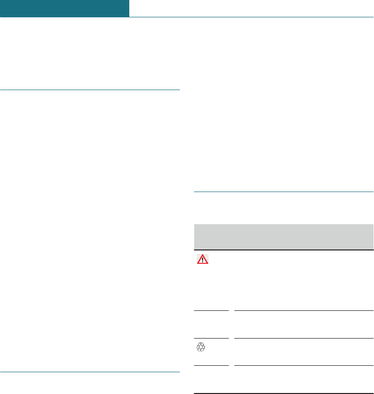
Vehicle identification number
The vehicle identification number is in the
engine compartment, on the right-hand side
of the vehicle.
The vehicle identification number is on the
type plate, on the right-hand side of the ve-
hicle.
Seite 13
Notes NOTES
13
Online Edition for Part no. 01402988211 - II/18
Draft
from BA-76

14
Online Edition for Part no. 01402988211 - II/18
Draft
from BA-76

QUICK REFERENCE
Your MINI in brief ................................................................................... 16
15
Online Edition for Part no. 01402988211 - II/18
Draft
from BA-76
Your MINI in brief
Opening and closing
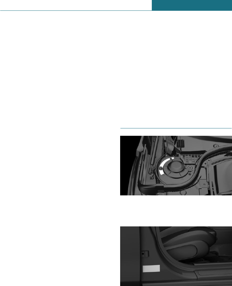
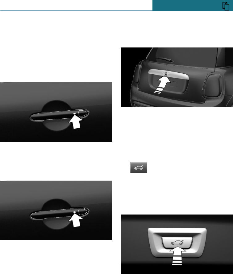
Buttons on the remote control
1Unlocking
2Locking
3Unlocking the tailgate
With automatic tailgate operation: open-
ing/closing tailgate
Unlocking the vehicle
Press the button on the remote con-
trol.
Depending on the settings, only the driver's
door or all vehicle access points are un-
locked.
If only the driver's door is unlocked, press
the button on the remote control again to
unlock the other vehicle access points.
Keep the button on the remote con-
trol pressed after unlocking.
The windows and the Glass Roof are opened
for as long as the button on the remote con-
trol is pressed.
Locking the vehicle
Press the button on the remote con-
trol.
All vehicle entrances are locked.
Keep the button on the remote con-
trol pressed after locking.
The windows and the Glass Roof are closed
for as long as the button on the remote con-
trol is pressed.
Central locking buttons
Overview
Central locking buttons.
Locking
Pressing the button locks the vehi-
cle when the front doors are closed.
Unlocking
Pressing button unlocks vehicle.
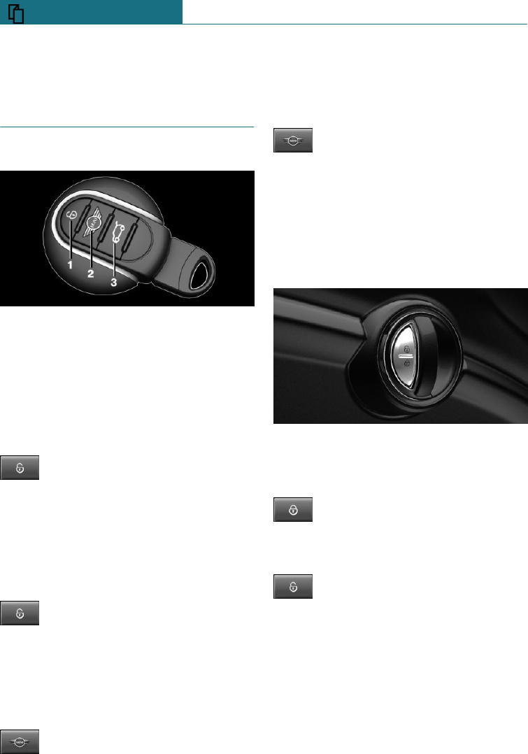
Comfort Access
Principle
This feature allows you to access the vehi-
cle without having to operate the remote
control.
Seite 16
QUICK REFERENCE Your MINI in brief
16 Online Edition for Part no. 01402988211 - II/18
Draft
from BA-76
Simply having the remote control with you,
for example in your trouser pocket, is suffi-
cient.
The vehicle automatically recognises the re-
mote control when it is in the immediate vi-
cinity or inside the vehicle.
Unlocking the vehicle
Press the button on the door handle of the
driver or front passenger door.
Locking the vehicle
Press the button on the door handle of the
driver or front passenger door.
Tailgate
Opening
Unlock the vehicle and press the button on
the tailgate.
–Unlock the vehicle and press the button
on the tailgate.
–If you are carrying the remote control,
press the button on the tailgate.
–Press and hold the button on the
remote control for approxi-
mately 1 second.
If applicable, the doors are also un-
locked.
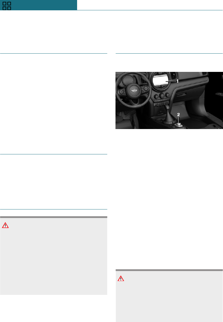
Closing
Press the button on the inside of the tail-
gate.
Seite 17
Your MINI in brief QUICK REFERENCE
17
Online Edition for Part no. 01402988211 - II/18
Draft
from BA-76
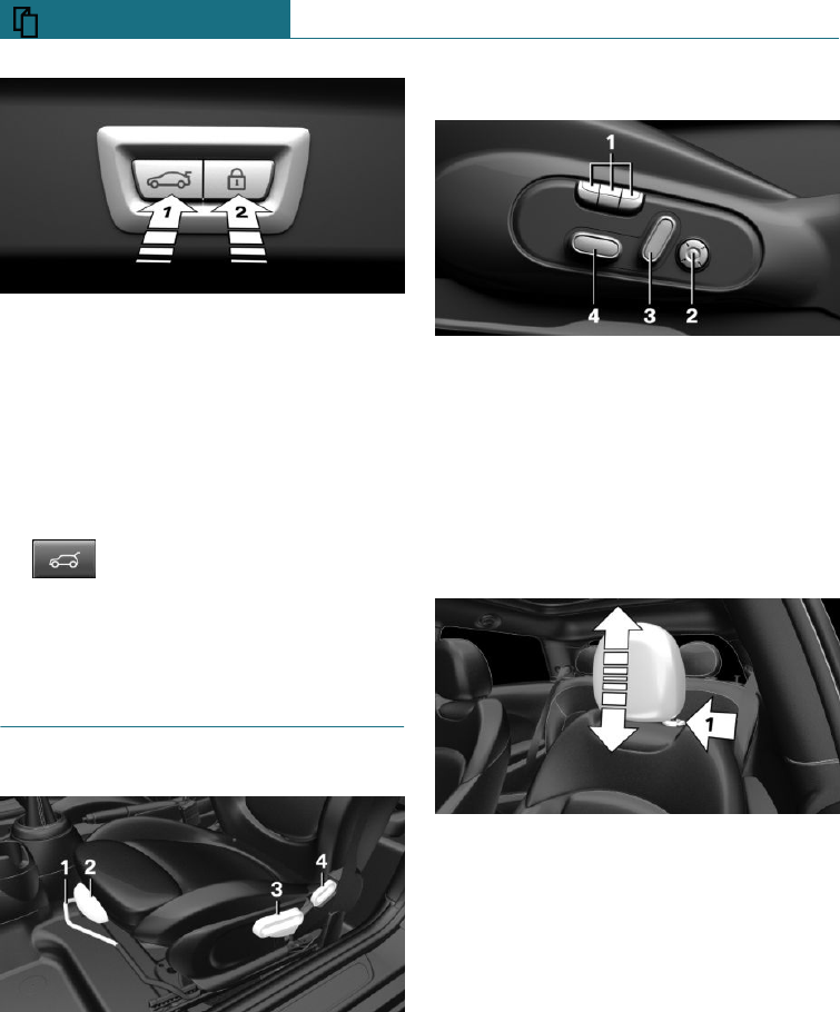
–Press the button on the inside of the
tailgate, arrow 1.
–Press the button, arrow 2.
The vehicle is locked after the tailgate
has been closed. To do this, the driver's
door must be closed and the remote con-
trol must be outside the vehicle in the
vicinity of the tailgate.
–Keep the button on the remote
control pressed until the tailgate
has closed.
Seats, mirrors and steering
wheel
Manually adjustable seats
1Forward/back
2Thigh support
3Height
4Backrest angle
Electrically adjustable seats
1Memory function
2Lumbar support
3Backrest angle
4Forward/back, height, seat angle
To adjust the head restraint
Height
–Upwards: push head restraint upwards.
–Downwards: press the button, arrow 1,
and slide the head restraint downwards.
Seite 18
QUICK REFERENCE Your MINI in brief
18 Online Edition for Part no. 01402988211 - II/18
Draft
from BA-76
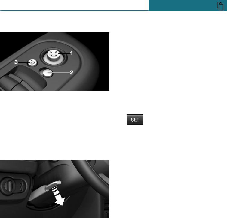
To adjust the exterior mirrors
1To adjust
2To select a mirror, automatic parking
function
3To fold in and out
To adjust the steering wheel
In four directions
1. Switch on the ignition.
2. Fold the lever downwards.
3. Move the steering wheel to the prefer-
red height and angle to suit your seated
position.
4. Swing the lever back up.
5. Switch off the ignition again if neces-
sary.
Memory function
Principle
The memory function enables the following
settings to be stored and retrieved when re-
quired:
–Seat position.
–Exterior mirror position.
Saving
1. Switch on the ignition.
2. Set the desired position.
3. Press the button. The LED in
button is illuminated.
4. Press the desired button 1 or 2 on the
seat while the LED is illuminated. The
LED is extinguished.
Recalling
The saved position is called up automati-
cally.
Press the desired button 1 or 2.
The operation is halted when you press a
seat adjustment switch or one of the mem-
ory buttons.
Adjusting the seat position on the driver's
side is interrupted after a short time during
the journey.
Seite 19
Your MINI in brief QUICK REFERENCE
19
Online Edition for Part no. 01402988211 - II/18
Draft
from BA-76
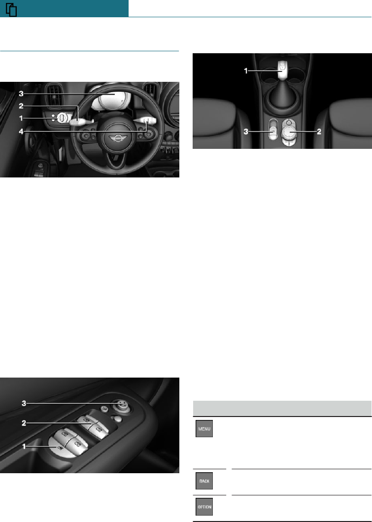
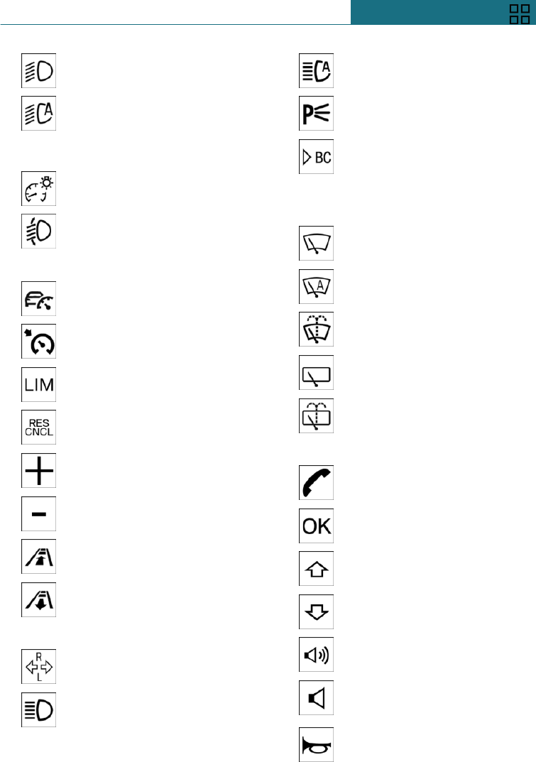
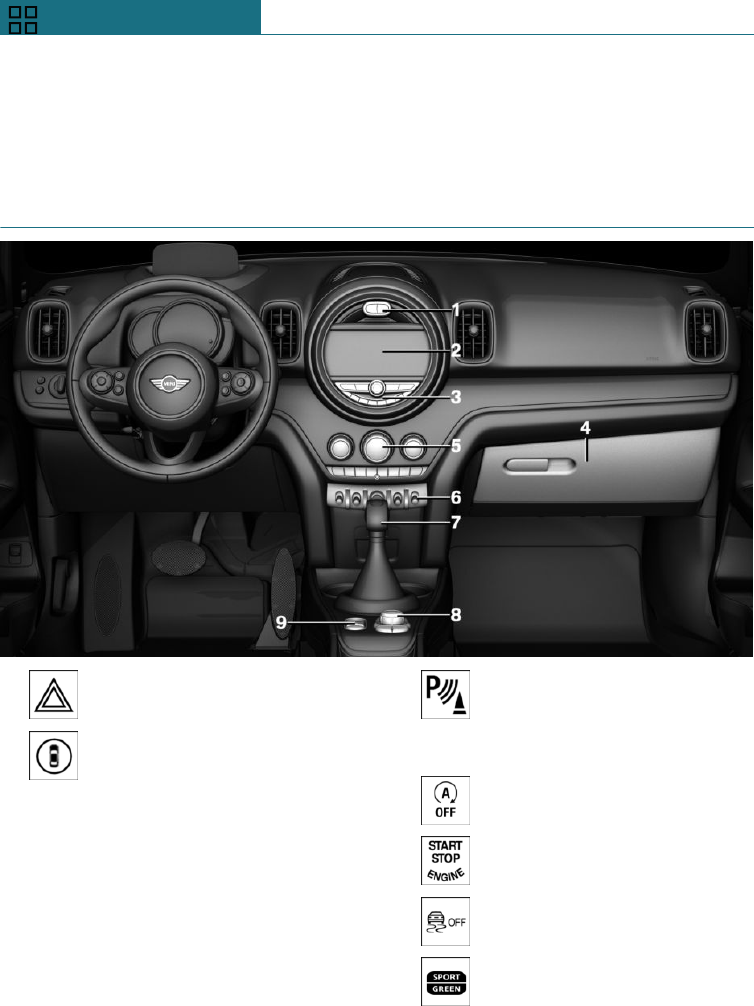
Displays and controls
Around the steering wheel
1Low-beam headlights, fog light
2High-beam headlights, flasher, indicator
3Instrument cluster
4Wiper system
Indicator and warning lamps
Instrument cluster
Indicator and warning lamps can illuminate
in a variety of combinations and colours.
When the engine starts or the ignition is
switched on, the functionality of some
lights is checked and they illuminate briefly.
Driver's door
1Safety switch
2Power window switches
3Exterior mirrors
Around the selector lever
1Selector lever
2Controller with buttons
3Parking brake
On-board monitor
Principle
The on-board monitor brings together the
functions of a number of switches. These
functions can be operated using the Con-
troller.
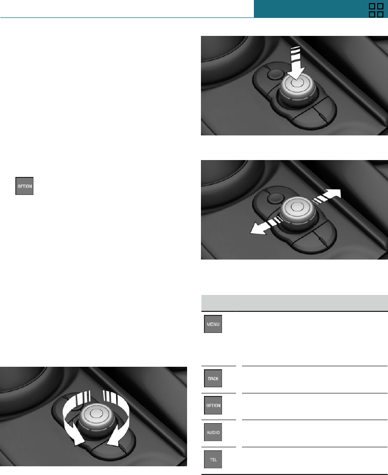
Controller
General
The buttons can be used to call up menus
directly. The Controller can be used to se-
lect menu items and perform settings.
Buttons on the Controller
Button Function
Press once: to call up the main
menu.
Press twice: to call up the last
used menus.
To call up the previous screen.
To call up the Options menu.
Seite 20
QUICK REFERENCE Your MINI in brief
20 Online Edition for Part no. 01402988211 - II/18
Draft
from BA-76
Button Function
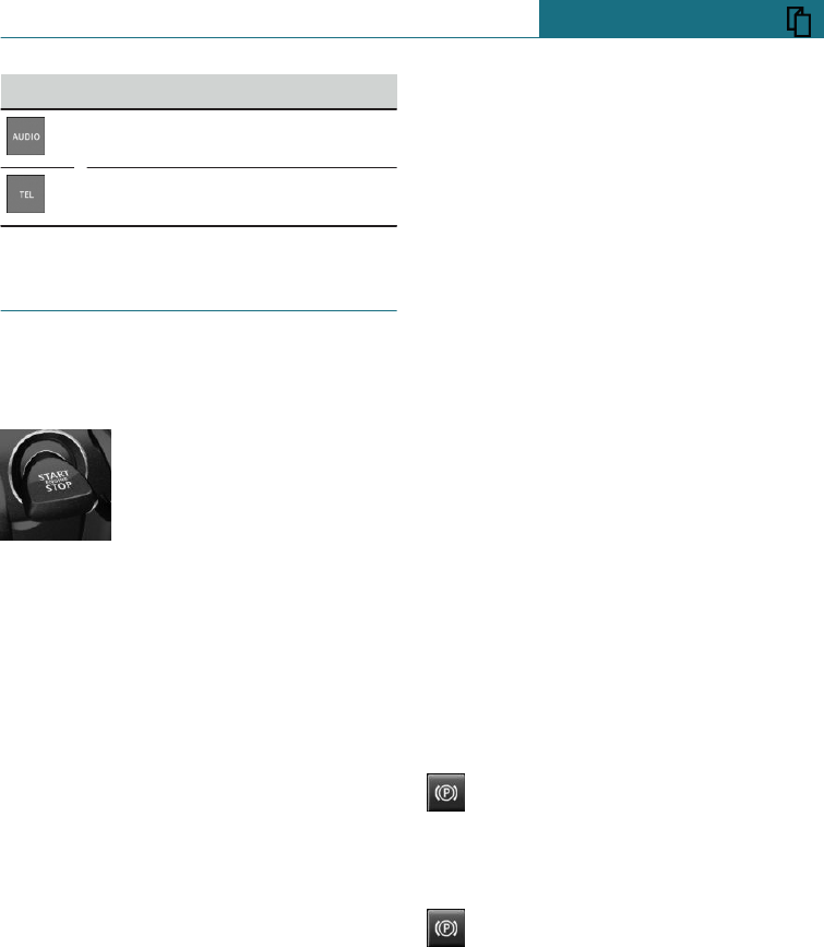
Call up the Audio menu.
To call up the Telephone menu.
Driving
Starting and stopping the engine
Ignition on/off
–On: press the start/stop
button.
Most of the indicator and
warning lamps are illumi-
nated for different lengths
of time.
–Off: press the start/stop button again.
All indicator lamps turn off.
–Radio ready state: with the ignition
switched off, press on the on/off button
on the radio or press the start/stop but-
ton when the engine is running.
Individual power consumers remain op-
erational.
Starting/stopping engine
Steptronic transmission: starting
1. Depress the brake pedal.
2. Engaging the selector lever in position P
or N.
3. Press the start/stop button.
Manual gearbox: starting
1. Depress the brake pedal.
2. Press the clutch and engage idle posi-
tion.
3. Press the start/stop button.
Steptronic transmission: stopping
1. Apply the parking brake when the vehi-
cle is stationary.
2. Engaging the selector lever in posi-
tion P.
3. Press the start/stop button.
Manual gearbox: stopping
1. Press the Start/Stop button when the
vehicle is at standstill.
2. Engage first gear or reverse.
3. Apply the parking brake.
Auto Start Stop function
Steptronic transmission: switches the en-
gine off automatically at a standstill to save
fuel. As soon as the brake pedal is released,
the engine starts automatically.
Manual gearbox: switches the engine off au-
tomatically at a standstill to save fuel. As
soon as the clutch pedal is released, the en-
gine starts automatically.
Parking brake
Engaging
Pull the switch.
LED and indicator lamp are illumina-
ted.
Releasing
Manual transmission: press the button
with the brake pedal depressed.
Steptronic transmission: press the switch
with the brake pedal depressed or selector
lever position P engaged.
LED and indicator lamp turn off.
The parking brake is released.
Seite 21
Your MINI in brief QUICK REFERENCE
21
Online Edition for Part no. 01402988211 - II/18
Draft
from BA-76
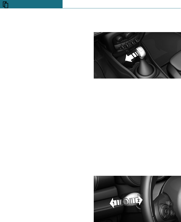
Manual gearbox
Shifting gears
During the shifting process into 5th/6th
gear level, push the gear shift lever to the
right, otherwise, to avoid inadvertent
switching to the 3rd or 4th gear.
Reverse gear
Engage this position only when the vehicle
is stationary.
To overcome the resistance, move the shift
lever firmly to the left towards the left and
engage the reverse gear with a gear shift
movement forwards.
Steptronic transmission
Selector lever positions
P Park position.
R reverse.
N neutral.
D drive position.
Only engage selector lever position P or R
when the vehicle is stationary.
Apply the brakes until ready to drive off,
otherwise the vehicle will move when a
drive position or reverse gear is selected.
Selector lever lock
A lock prevents an inadvertent change from
selector lever position P to another selector
lever position and, depending on the trans-
mission version, inadvertent shifting from
selector lever position P or R.
To cancel the lock: with the brake pedal
pressed, press the button on the front or
side of the selector lever.
Steptronic transmission, Sport and
manual operation
Sport programme:
Press the selector lever out of selector lever
position D to the left.
Manual operation:
–To shift down: press the selector lever
forwards.
–To shift up: pull the selector lever back-
wards.
High-beam headlights, headlight
flasher, turn indicators, parking
lights
High-beam headlights, headlight
flasher
Push the lever forwards or pull it back.
–High-beam headlights, arrow 1.
–Headlight flasher, arrow 2.
Seite 22
QUICK REFERENCE Your MINI in brief
22 Online Edition for Part no. 01402988211 - II/18
Draft
from BA-76
Turn indicator
–On: press the lever beyond the resist-
ance point.
–Off: lightly tip the lever as far as the re-
sistance point.
–Triple turn signal: lightly tip the lever up
or down.
–Indicating a turn briefly: press the lever
as far as the resistance point and hold it
there for as long as you wish to indicate
a turn.
Parking light
Illuminate the vehicle on one side.
–On: with the ignition switched off, push
the lever upwards or downwards beyond
the resistance point for approximately
2 seconds.
–Off: press the lever briefly in the oppo-
site direction as far as the resistance
point.
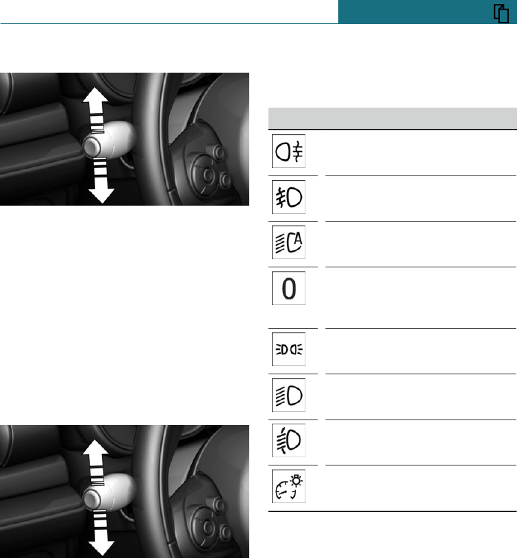
Light and lighting
Light functions
Symbol Function
Rear fog lights.
Front fog lights.
Automatic driving lights control.
Lights off.
Automatic driving lights control.
Daytime driving lights.
Side lights.
Low-beam headlights.
Manual headlight beam throw
adjustment.
Instrument lighting.
Seite 23
Your MINI in brief QUICK REFERENCE
23
Online Edition for Part no. 01402988211 - II/18
Draft
from BA-76
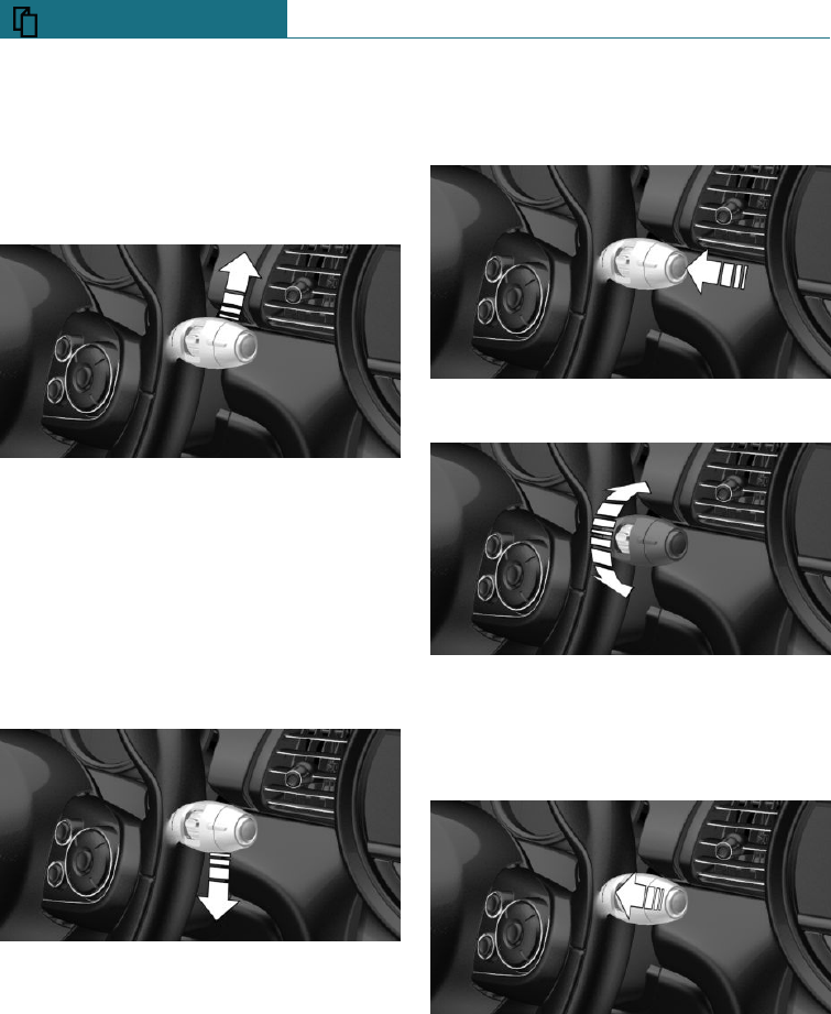
Wiper system
Switching the wipers on/off and flick-
wiping
Switching on
Tap the lever up or push it beyond the re-
sistance point.
–Normal wiping speed: press upwards
once.
–Rapid wiping speed: press upwards
twice or press once beyond the resist-
ance point.
Switching off and flick-wiping
Press the lever down.
–Switching off fast mode: press down-
wards twice.
–Switching off normal mode: press down-
wards once.
–To flick-wipe: press downwards once.
Rain sensor
Activating/deactivating
Press the button on the wiper lever.
Adjust sensitivity:
Turn the knurled wheel on the wiper lever.
To clean the windscreen
Pull the lever.
Seite 24
QUICK REFERENCE Your MINI in brief
24 Online Edition for Part no. 01402988211 - II/18
Draft
from BA-76
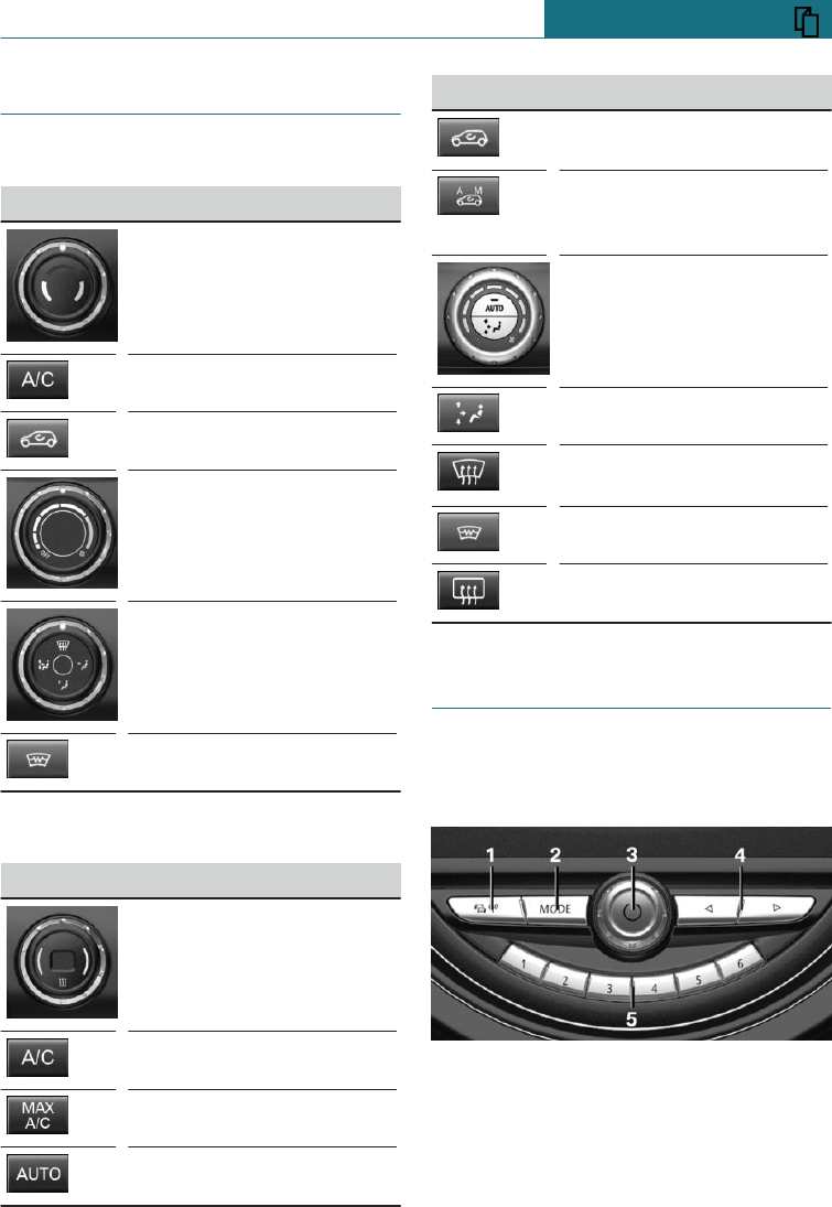
Air conditioning
Air conditioning system
Button Function
Temperature.
Cooling function.
Recirculated-air mode.
Adjust the air flow man-
ually.
Adjust the air distribution
manually.
Windscreen heating.
Automatic air conditioning
Button Function
Temperature.
Cooling function.
Maximum cooling.
AUTO program.
Button Function
Recirculated-air mode.
Automatic air recirculation
control AUC/recirculated-
air mode.
Adjust the air flow man-
ually.
Air distribution, manual.
Defrost and demist the win-
dows.
Windscreen heating.
Rear window heating.
Infotainment
Radio
Controls
1Traffic information
2Changing the entertainment source
3Sound output on/off, volume
Seite 25
Your MINI in brief QUICK REFERENCE
25
Online Edition for Part no. 01402988211 - II/18
Draft
from BA-76

4Changing station/track
5Favourites buttons
Mobile telephone register
Once the mobile telephone has been con-
nected in the vehicle, it can be operated us-
ing the on-board monitor, the buttons on
the steering wheel and by voice control.
1. "My MINI"
2. "System settings"
3. "Mobile devices"
4. "Connect new device"
The Bluetooth name of the vehicle is
displayed in the Control Display.
5. To perform other operations on the mo-
bile telephone; see the user manual of
the mobile telephone: for example find-
ing/connecting Bluetooth device or new
device.
The Bluetooth name of the vehicle is
shown on the display of the mobile tele-
phone. Select the Bluetooth name of the
vehicle.
6. Depending on the mobile device, either
a control number is displayed, or you
will have to enter the control number
yourself.
–Compare the control number shown
on the Control Display with the con-
trol number in the device display.
Confirm the control number in the
device and on the Control Display.
–Enter the same control number on
the device and via the on-board mon-
itor then confirm.
The device is connected and displayed
in the device list.
The mobile telephone is connected and
shown in the first position on the list of mo-
bile telephones.
Telephony
Accepting a call
Incoming calls can be accepted using the
on-board monitor or using the button on the
steering wheel.
Using the on-board monitor
"Accept"
Via button on the steering wheel
Press the button.
Dialling a number
1. "Communication"
2. "Dial number"
3. Select the numbers individually.
4. Select the symbol.
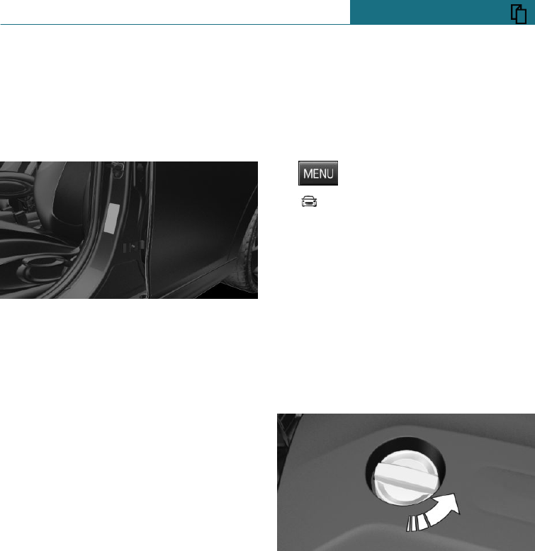
Refuelling stop
Refuelling
Fuel tank cap
1. Tap the rear edge of the fuel filler flap to
open it.
2. Turn the fuel tank cap anticlockwise.
3. Place the fuel tank cap in the holder on
the fuel filler flap.
Petrol
For optimal fuel consumption, the petrol
should be sulphur-free or low in sulphur
content.
Only refuel with unleaded petrol without
metallic additives.
Information about the recommended petrol
grade is provided in the Owner's Handbook.
Seite 26
QUICK REFERENCE Your MINI in brief
26 Online Edition for Part no. 01402988211 - II/18
Draft
from BA-76
Diesel
Diesel fuel to DIN EN 590 standard.
Wheels and tyres
Tyre inflation pressure information
The tyre inflation pressures are on the plate
on the door pillar.
Checking the tyre inflation pressure
Check regularly and adjust as necessary:
–At least twice a month.
–Before a long journey.
After adjusting the tyre inflation
pressure
Reinitialise runflat indicator.
Reset the Tyre Pressure Monitor.
Electronic oil measurement
Requirements
A current measurement is available after
approximately 30 minutes of the journey.
With a shorter journey, the status of the
last sufficiently long journey is shown.
In the detailed measurement in addition:
–Vehicle is on a level street and with the
engine at operating temperature.
–Manual gearbox:
Gear lever in idling position, clutch and
accelerator pedal not applied.
–Steptronic transmission:
Selector lever in selector lever position
N or P and accelerator pedal not applied.
Displaying the engine oil level
On the radio:
1. Press the button.
2. "Vehicle information"
3. "Vehicle status"
4. "Engine oil level"
The engine oil level is displayed.
Adding engine oil
General
Switch off the ignition and safely park the
vehicle before topping up with engine oil.
Topping up
Do not top up engine oil unless a message is
displayed in the instrument cluster.
Note the top-up quantity in the message.
Ensure not to top up with too much engine
oil.
Note recommended engine oil types.
Seite 27
Your MINI in brief QUICK REFERENCE
27
Online Edition for Part no. 01402988211 - II/18
Draft
from BA-76
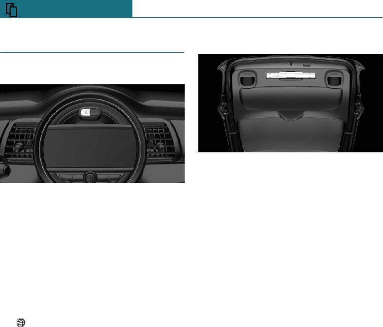
Breakdown Assist
Hazard warning lights
The button is situated above the Control
Display.
Breakdown Assist
Mobile Service
Available by phone twenty-four hours a day,
seven days a week in many countries.
Breakdown assistance
1. "Services"
2. "Mobile Care"
3. "Start service"
Contact to the mobile service is resaved.
A telephone number may be displayed.
Select it to dial the telephone number
using a connected mobile telephone.
Warning triangle, first-aid kit
First-aid kit
The first-aid kit is in the boot.
Warning triangle
The warning triangle is located in the tail-
gate. To remove, release the mounts.
Seite 28
QUICK REFERENCE Your MINI in brief
28 Online Edition for Part no. 01402988211 - II/18
Draft
from BA-76

Seite 29
Your MINI in brief QUICK REFERENCE
29
Online Edition for Part no. 01402988211 - II/18
Draft
from BA-76

30
Online Edition for Part no. 01402988211 - II/18
Draft
from BA-76

OVERVIEW
Driving area ............................................................................................... 32
On-board monitor ..................................................................................... 36
General settings ....................................................................................... 41
Owner's Handbook media ...................................................................... 50
31
Online Edition for Part no. 01402988211 - II/18
Draft
from BA-76
Driving area
Vehicle equipment
This chapter describes all standard, country-
specific and special equipment available for
the model series. Therefore equipment
which is not installed in your vehicle, for
example on account of the optional equip-
ment selected or the country specification,
may also be described here. This also ap-
plies to safety-relevant functions and sys-
tems. Comply with the relevant laws and
regulations when using the corresponding
functions and systems.
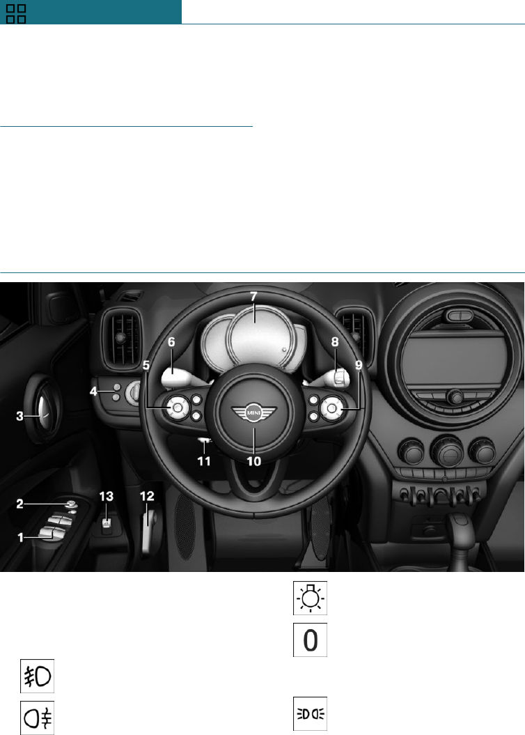
Around the steering wheel
1Power window switches 72
2Exterior mirror operation 88
3Buttons of the central locking 61
4Lights
Front fog lights 145
Rear fog lights 145
Light switch 141
Lights off
Automatic driving lights con-
trol 143
Daytime driving lights 143
Side lights 141
Seite 32
OVERVIEW Driving area
32 Online Edition for Part no. 01402988211 - II/18
Draft
from BA-76
Low-beam headlights 142
Automatic driving lights con-
trol 143
Cornering light 143
High-beam assistance 144
Instrument lighting 146
Manual headlight beam throw
adjustment 144
5Buttons on steering wheel, left
Camera-based Cruise Control
on/off 175
Cruise Control on/off 182
Speed limiter 167
To interrupt, resume Cruise
Control
Cruise Control: to increase the
speed
Cruise Control: to decrease the
speed
Camera-based Cruise Control:
to reduce the distance
Camera-based Cruise Control:
to increase the distance
6Steering-column lever, left
Turn indicator 110
High-beam headlights, head-
light flasher 110
High-beam assistance 144
Parking lights 142
On-board computer 135
7Instrument cluster 124
8Steering-column lever, right
Windscreen wipers 110
Rain sensor 111
Cleaning windows 112
Rear wipers 113
Cleaning rear window 113
9Buttons on steering wheel, right
Telephone 258
Confirm selection 135
Select back 135
Select forward 135
Volume up
Volume down
10 Horn, entire area
Seite 33
Driving area OVERVIEW
33
Online Edition for Part no. 01402988211 - II/18
Draft
from BA-76
11 To adjust the steering wheel 90
12 To release the bonnet 294
13 With automatic tailgate operation: oper-
ate the tailgate 65
Around the centre console
1Hazard warning lights 316
Intelligent Safety 159
2Control Display 36
3Radio/Multimedia
4Glove box 207
5Climate 195
6Park Distance Control,
PDC 184
Rear-view camera 187
Park Assistant 190
Auto Start Stop function 105
Engine start/stop and ignition
on/off 102
Dynamic Stability Control,
DSC 170
MINI Driving Modes
switch 172
Seite 34
OVERVIEW Driving area
34 Online Edition for Part no. 01402988211 - II/18
Draft
from BA-76
7Steptronic transmission selector
lever 116 Manual transmission selector
lever 115
8Controller with buttons 37
9Parking brake 108
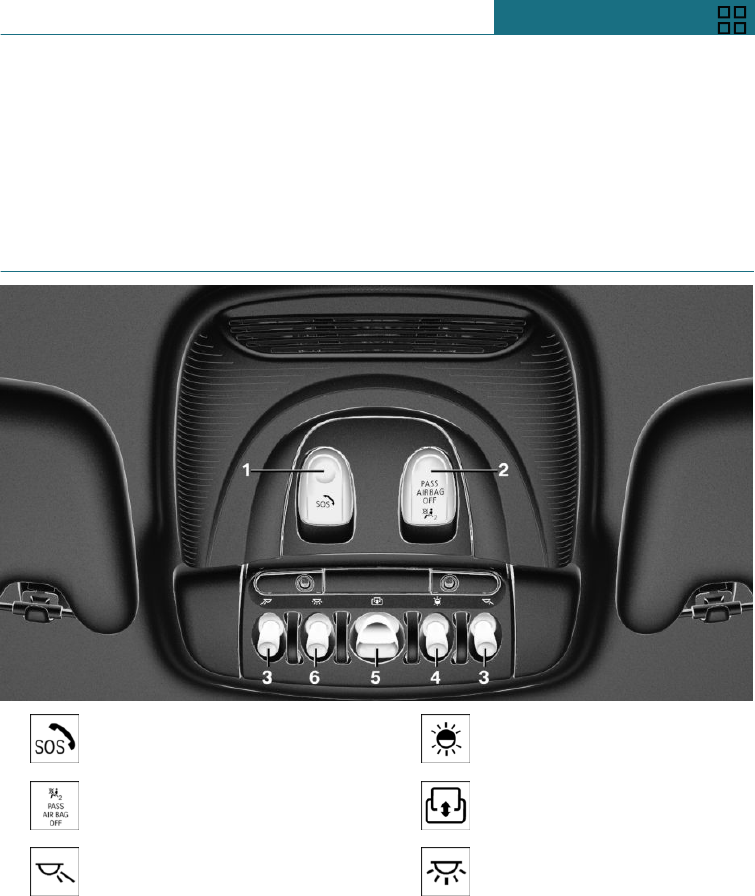
Around the roof lining
1Emergency call, SOS 316
2Front passenger airbag indica-
tor lamp 151
3Reading lights 147
4Ambient lighting 147
5Panorama Glass Roof 74
6Interior light 146
Seite 35
Driving area OVERVIEW
35
Online Edition for Part no. 01402988211 - II/18
Draft
from BA-76
On-board monitor
Vehicle equipment
This chapter describes all standard, country-
specific and special equipment available for
the model series. Therefore equipment
which is not installed in your vehicle, for
example on account of the optional equip-
ment selected or the country specification,
may also be described here. This also ap-
plies to safety-relevant functions and sys-
tems. Comply with the relevant laws and
regulations when using the corresponding
functions and systems.
Principle
The on-board monitor brings together the
functions of a number of switches. These
functions can be operated using the Con-
troller.
Safety note
WARNING
Operating integrated informations systems
and communication devices during the
journey may distract you from the traffic.
You could lose control of the vehicle.
There is a danger of accidents. Only oper-
ate the systems or devices if permissible
in the traffic situation. Stop if necessary
and operate the systems or devices with
the vehicle at a standstill.
Controls
Overview
1Control Display
2Controller with buttons
Control Display
General
To clean the Control Display, comply with
the information regarding care, see
page 329.
If the Control Display is exposed to very
high temperatures, for example because of
strong sunlight, there may be a reduction in
brightness and the Control Display may
even switch itself off. Normal functions will
be restored when the temperature is re-
duced, for example by shading or using the
air conditioning system.
Safety note
NOTE
Objects located in front of the Control Dis-
play may slip and damage the Control Dis-
play. There is a danger of damage to prop-
erty. Do not place objects in front of the
Control Display.
Seite 36
OVERVIEW On-board monitor
36 Online Edition for Part no. 01402988211 - II/18
Draft
from BA-76
Switching on/off automatically
The Control Display is switched on automat-
ically after unlocking.
In certain situations, the Control Display is
switched off automatically, for example if no
operation is performed on the vehicle for
several minutes.
Switching on/off manually
The Control Display can also be switched off
manually.
1. Press the button.
2. "Switch off control display"
Press the Controller or any button on the
Controller to switch it back on again.
Controller
General
The buttons can be used to call up menus
directly. The Controller can be used to se-
lect menu items and perform settings.
Operation
–Turning.
–Pressing.
–Tilting in two directions.
Buttons on the Controller
Button Function
Press once: to call up the main
menu.
Press twice: to call up the last
used menus.
To call up the previous screen.
To call up the Options menu.
Call up the Audio menu.
To call up the Telephone menu.
Seite 37
On-board monitor OVERVIEW
37
Online Edition for Part no. 01402988211 - II/18
Draft
from BA-76
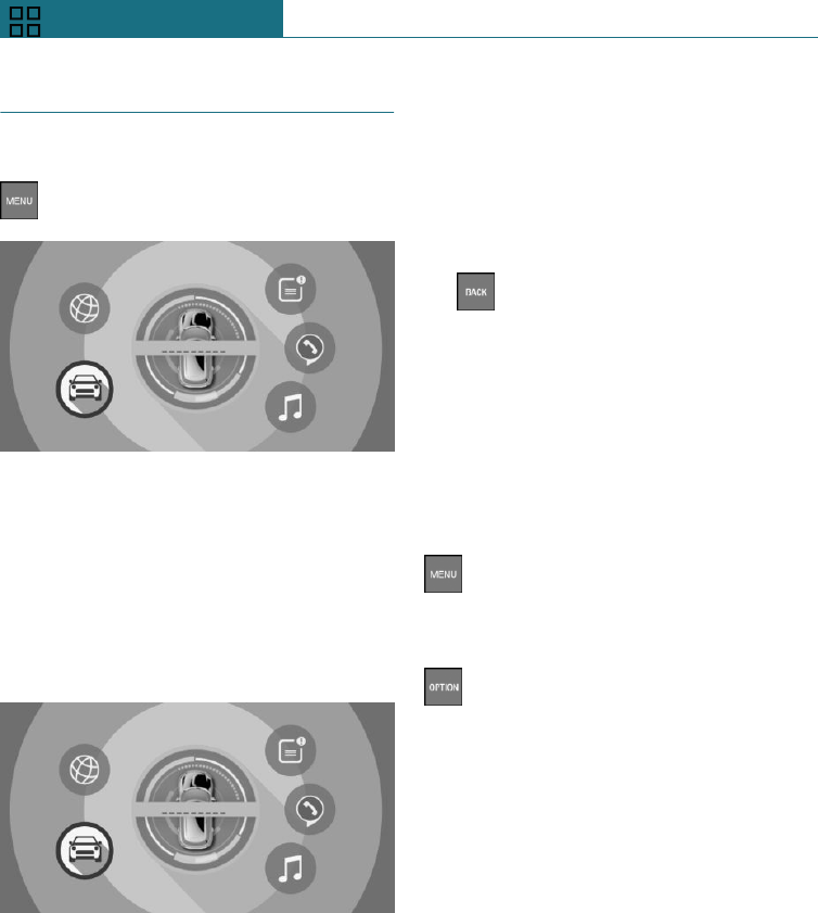
Operation using the Controller
Calling up the main menu
Press the button.
The main menu is displayed.
All on-board monitor functions can be called
up via the main menu.
Selecting a menu item
Highlighted menu items can be selected.
1. Turn the Controller until the desired
menu item is highlighted.
2. Press the Controller.
Menu items in the Owner's
Handbook
In this Owner's Handbook, the menu items
that are to be selected are shown in quota-
tion marks, for example "System settings".
Switching between screens
After a menu item has been selected, for ex-
ample "System settings", a new screen is
displayed.
–Tilt the Controller to the left.
The current screen is closed and the
previous screen is displayed.
– Press the button.
The previous screen is opened again.
–Tilt the Controller to the right.
The new screen is opened.
An arrow indicates that further screens can
be called up.
Calling up recently used menus
The recently used menus can be displayed.
Press the button twice.
Calling up the Options menu
Press the button.
The "Options" menu is displayed.
The Options menu consists of various areas:
–Operating options for the selected main
menu, for example for "Media/Radio".
–If applicable, other operating options for
the selected menu, for example "Save
station".
To adjust the settings
1. Select a field.
2. Turn the Controller until the desired set-
ting is displayed.
3. Press the Controller.
Enabling/disablingfunctions
Some menu items are preceded by a check-
box. This indicates whether the function is
Seite 38
OVERVIEW On-board monitor
38 Online Edition for Part no. 01402988211 - II/18
Draft
from BA-76
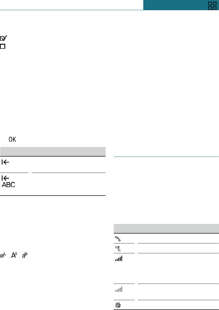
enabled or disabled. Selecting the menu
item enables or disables the function.
Function is enabled.
Function is disabled.
Entering letters and numbers
General
Letters and numbers can be entered via the
Controller.
The keyboard display changes automati-
cally.
Entry
1. Turn the Controller: to select letters or
numbers.
2. : to confirm your entry.
Symbol Function
Press Controller: to delete
letters or numbers.
or
Press and hold the Controller:
to delete all letters or num-
bers.
Changing between upper/lower case,
numbers and characters
Depending on the menu, upper and lower
case letters as well as numbers and symbols
can be entered:
Without navigation system
Select the symbol.
Entry comparison
When entering names and addresses, the
selection is gradually narrowed down and
possibly supplemented with every subse-
quent letter that you enter.
Inputs are continuously compared with the
data saved in the vehicle.
Only letters for which data is available are
offered for entry.
Operating alphabetical lists
For alphabetic lists with more than 30 en-
tries, the letters for which entries are avail-
able can be shown on the left side.
1. Turn the Controller quickly to the left or
right.
All the letters for which an entry is
available are shown on the left-hand
side.
2. Select the initial letter of the desired en-
try.
The first entry of the selected letter is
displayed.
Status information
General
The status field is located in the top area of
the Control Display. Status information is
displayed in the form of symbols.
Symbols in the status field
Telephone
Symbol Meaning
Incoming or outgoing call.
Missed call.
Reception level of mobile tele-
phone network.
Symbol flashes: searching for
network.
No mobile telephone network
available.
Data transfer not possible.
Seite 39
On-board monitor OVERVIEW
39
Online Edition for Part no. 01402988211 - II/18
Draft
from BA-76
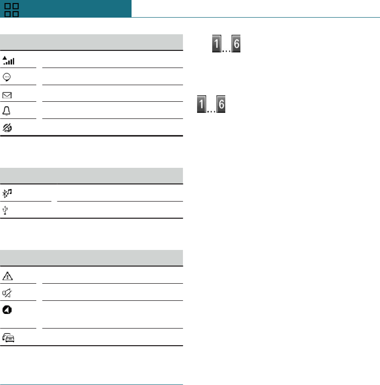
Symbol Meaning
Roaming active.
Text message received.
Message received.
Reminder.
Sending not possible.
Entertainment
Symbol Meaning
Bluetooth audio.
USB audio interface.
Other functions
Symbol Meaning
Check Control message.
Sound output switched off.
Determining the current vehicle
position.
Traffic information.
Favourites buttons
General
On-board monitor functions, for example
radio stations, telephone numbers and
shortcuts to the menu, can be saved to Fa-
vourites buttons and called up directly.
The settings are saved for the currently
used driver profile.
Saving a function
1. Select the function using the on-board
monitor.
2. Press and hold the desired but-
ton until a signal sounds.
Performing a function
Press the button.
The function is carried out immedi-
ately. If you have selected a telephone num-
ber, for example, the connection will also be
established.
Displaying the button assignment
Touch the buttons with your finger. Do not
wear gloves or use objects.
The button assignment is displayed at the
top edge of the screen.
Clearing the button assignment
1. Press and hold buttons 1 and 6 simulta-
neously for approximately 5 seconds.
2. "OK"
Seite 40
OVERVIEW On-board monitor
40 Online Edition for Part no. 01402988211 - II/18
Draft
from BA-76

General settings
Vehicle equipment
This chapter describes all standard, country-
specific and special equipment available for
the model series. Therefore equipment
which is not installed in your vehicle, for
example on account of the optional equip-
ment selected or the country specification,
may also be described here. This also ap-
plies to safety-relevant functions and sys-
tems. Comply with the relevant laws and
regulations when using the corresponding
functions and systems.
Language
To set the language
Using the on-board monitor:
1. "My MINI"
2. "System settings"
3. "Language"
4. "Language:"
5. Select the desired setting.
The setting is saved for the currently used
driver profile.
Time
Setting the time
Using the on-board monitor:
1. "My MINI"
2. "System settings"
3. "Date and time"
4. "Time:"
5. Turn the Controller until the desired
hours are displayed.
6. Press the Controller.
7. Turn the Controller until the desired mi-
nutes are displayed.
8. Press the Controller.
Setting the time format
Using the on-board monitor:
1. "My MINI"
2. "System settings"
3. "Date and time"
4. "Time format:"
5. Select the desired setting.
The setting is saved for the currently used
driver profile.
Date
Setting the date
Using the on-board monitor:
1. "My MINI"
2. "System settings"
3. "Date and time"
4. "Date:"
5. Turn the Controller until the desired day
is displayed.
6. Press the Controller.
7. Alter the setting for month and year.
Seite 41
General settings OVERVIEW
41
Online Edition for Part no. 01402988211 - II/18
Draft
from BA-76

Setting the date format
Using the on-board monitor:
1. "My MINI"
2. "System settings"
3. "Date and time"
4. "Date format:"
5. Select the desired setting.
The setting is saved for the currently used
driver profile.
Setting units of measurement
It is possible to select the units of measure-
ment for various values, for example fuel
consumption, distances and temperature.
Using the on-board monitor:
1. "My MINI"
2. "System settings"
3. "Units"
4. Select the desired menu item.
5. Select the desired setting.
The setting is saved for the currently used
driver profile.
Activating/deactivating dis-
play of the current vehicle po-
sition
Principle
If vehicle tracking is activated, the current
vehicle position can be displayed in the
MINI Connected app.
Activating/deactivating
Using the on-board monitor:
1. "My MINI"
2. "Vehicle settings"
3. "Vehicle tracking"
4. "Vehicle tracking"
5. Select the desired setting.
Activating/deactivating infor-
mation windows
Information windows are automatically
shown on the Control Display for some
functions. Some of these information win-
dows can be activated or deactivated.
Using the on-board monitor:
1. "My MINI"
2. "System settings"
3. "Pop-ups"
4. Select the desired setting.
The setting is saved for the currently used
driver profile.
Control Display
Brightness
Using the on-board monitor:
1. "My MINI"
2. "System settings"
3. "Displays"
4. "Control display"
5. "Brightness at night"
6. Turn the Controller until the desired
brightness is obtained.
7. Press the Controller.
Seite 42
OVERVIEW General settings
42 Online Edition for Part no. 01402988211 - II/18
Draft
from BA-76
The setting is saved for the currently used
driver profile.
Depending on the lighting conditions, the
brightness adjustment may not be immedi-
ately apparent.
Screen saver
If no entries were made via the on-board
monitor, the screen saver can be displayed
after a set time.
Using the on-board monitor:
1. "My MINI"
2. "System settings"
3. "Displays"
4. "Control display"
5. "Screensaver"
6. Select the desired setting.
The setting is saved for the currently used
driver profile.
Messages
Principle
The menu shows all messages received by
the vehicle, centrally in the form of a list.
General
The following messages can be displayed:
–Traffic messages.
–Check Control messages.
–Service requirement messages.
Messages are additionally displayed in the
status field.
Calling up messages
Using the on-board monitor:
1. "Notifications"
2. Select the required message.
The associated menu is opened and the
message displayed.
Deleting messages
All messages which are not Check Control
messages can be deleted from the list.
Check Control messages remain for as long
as they are relevant.
Using the on-board monitor:
1. "Notifications"
2. Select the required message if neces-
sary.
3. Press the button.
4. "Delete this notification" or "Delete all
notifications"
Settings
The following settings can be performed:
–Select the applications from which mes-
sages are permitted.
–Sort the sequence of messages by date
or priority.
Using the on-board monitor:
1. "My MINI"
2. "System settings"
3. "Notifications"
4. Select the desired setting.
Data protection
Data transfer
Principle
The vehicle offers various functions which
require data to be transferred to MINI or a
service provider. The transfer of data can be
deactivated for some functions.
Seite 43
General settings OVERVIEW
43
Online Edition for Part no. 01402988211 - II/18
Draft
from BA-76

General
If data transfer has been deactivated for a
function, then that function cannot be used.
Only perform settings with the vehicle at a
standstill.
Activating/deactivating data transfer
Follow the instructions on the Control Dis-
play.
Using the on-board monitor:
1. Switch on the ignition.
2. "My MINI"
3. "System settings"
4. "Data privacy"
5. Select the desired setting.
Deleting personal data in the
vehicle
Principle
Depending on use, the vehicle stores per-
sonal data such as saved radio stations. This
personal data can be permanently deleted
using on-board monitor.
General
The following data is deleted, depending on
the equipment:
–Driver profile settings.
–Saved radio stations.
–Saved Favourites buttons.
–Trip and on-board computer values.
–Phone book.
It can take up to 15 minutes in total to de-
lete data.
Operating requirements
Data can only be deleted with the vehicle at
a standstill.
Deleting data
Follow the instructions on the Control Dis-
play.
Using the on-board monitor:
1. Switch on the ignition.
2. "My MINI"
3. "System settings"
4. "Data privacy"
5. "Delete personal data"
6. "Delete personal data"
7. "OK"
8. Exit and lock the vehicle.
Deletion is completed after 15 minutes.
If not all data is deleted, repeat the deletion
process if required.
Cancelling deletion
Start the engine to cancel data deletion.
Connections
Principle
Various connection types are available for
using mobile devices in the vehicle. The
connection type to select depends on the
mobile device and the desired function.
General
The following overview shows possible
functions and the appropriate connection
types for them. The level of functionality de-
pends on the mobile device.
Seite 44
OVERVIEW General settings
44 Online Edition for Part no. 01402988211 - II/18
Draft
from BA-76
Function Connec-
tion type
Making calls with using the
hands-free system.
Operating telephone func-
tions via the on-board moni-
tor.
Bluetooth.
Playing music from the
smartphone or the audio
player.
Bluetooth
or USB.
USB storage medium:
Music playback.
USB.
The following connection types require a
one-off registration process with the vehi-
cle:
–Bluetooth.
Registered devices are then automatically
recognised and connected to the vehicle.
Safety note
WARNING
Operating integrated informations systems
and communication devices during the
journey may distract you from the traffic.
You could lose control of the vehicle.
There is a danger of accidents. Only oper-
ate the systems or devices if permissible
in the traffic situation. Stop if necessary
and operate the systems or devices with
the vehicle at a standstill.
Compatible devices
General
Information about mobile devices compati-
ble with the vehicle is available at
www.mini.com/connectivity.
Malfunctions may occur when using unlis-
ted devices or different software versions.
Viewing the vehicle identification
number and software part number
When looking for compatible devices, the
vehicle identification number and software
part number may have to be stated. These
numbers can be displayed in the vehicle.
Using the on-board monitor:
1. "My MINI"
2. "System settings"
3. "Mobile devices"
4. "Settings"
5. "Bluetooth information"
6. "System information"
Bluetooth connection
Operating requirements
–Compatible device, see page 45, with
Bluetooth interface.
–The remote control is in the vehicle.
–The device is operational.
–Bluetooth is activated on the device and
in the vehicle, see page 45.
–The device may require certain Blue-
tooth default settings, for example visi-
bility, see the user manual of the device.
Switching on Bluetooth
Using the on-board monitor:
1. "My MINI"
2. "System settings"
3. "Mobile devices"
4. "Settings"
5. "Bluetooth"
Seite 45
General settings OVERVIEW
45
Online Edition for Part no. 01402988211 - II/18
Draft
from BA-76

Registering the mobile device with the
vehicle
Using the on-board monitor:
1. "My MINI"
2. "System settings"
3. "Mobile devices"
4. "Connect new device"
5. Select the functions for which the de-
vice will be used:
– "Telephone"
– "Bluetooth audio"
The Bluetooth name of the vehicle is
displayed in the Control Display.
6. On the mobile device, search for Blue-
tooth devices in the vicinity.
The Bluetooth name of the vehicle is
shown on the display of the mobile de-
vice.
Select the Bluetooth name of the vehi-
cle.
7. Depending on the mobile device, either
a control number is displayed, or you
will have to enter the control number
yourself.
–Compare the control number shown
on the Control Display with the con-
trol number in the device display.
Confirm the control number in the
device and on the Control Display.
–Enter the same control number on
the device and via the on-board mon-
itor then confirm.
The device is connected and displayed
in the device list.
If the connection was not successful: Fre-
quently Asked Questions, see page 46.
Frequently Asked Questions
There may be instances where the mobile
device does not function as expected, even
though all preconditions have been met and
all the necessary steps have been carried
out in the correct order. Nevertheless, the
mobile device does not function as expec-
ted.
In such cases, the following explanations
may provide assistance:
Why could the mobile telephone not be
paired or connected?
–Too many Bluetooth devices are paired
to the mobile telephone or the vehicle.
In the vehicle, delete Bluetooth connec-
tions with other devices.
Delete all known Bluetooth connections
from the device list on the mobile tele-
phone and start a new device search.
–The mobile telephone is in power-save
mode or the battery is low.
Charge up the mobile telephone.
Why does the mobile telephone no longer
respond?
–The applications on the mobile tele-
phone are no longer functioning.
Switch the mobile telephone off and on
again.
–Ambient temperatures may be too high
or too low to operate the mobile tele-
phone.
Do not subject the mobile telephone to
extreme ambient conditions.
Why is it not possible to operate the tele-
phone functions via the on-board monitor?
–The mobile telephone may not be con-
figured correctly, for example as a Blue-
tooth audio device.
Connect the mobile telephone with the
telephone function.
Why are no phone book entries, not all en-
tries or incomplete entries displayed?
–The transfer of the phone book entries is
not yet completed.
Seite 46
OVERVIEW General settings
46 Online Edition for Part no. 01402988211 - II/18
Draft
from BA-76

–Under certain circumstances only the
phone book entries saved in the mobile
telephone or on the SIM card are trans-
ferred.
–It is possible that phone book entries
with special characters cannot be dis-
played.
–It may not be possible to transfer con-
tacts from social networks.
–The number of phone book entries to be
saved is too high.
–The data volume of the contact is too
large, for example due to saved informa-
tion such as memos.
Reduce the data volume of the contact.
–A mobile telephone is only connected as
an audio source.
Reconfigure the mobile telephone and
connect it with the telephone function.
How can the telephone connection quality
be improved?
–Depending on the mobile telephone, it
may be possible to adjust the strength of
the Bluetooth signal on the mobile tele-
phone.
If all the points on the list have been re-
viewed and the desired function cannot be
performed, contact the Hotline, a Service
Partner of the manufacturer or another
qualified Service Partner or a specialist
workshop.
USB connection
General
Mobile devices with a USB port are connec-
ted to the USB interface.
–Mobile telephones.
–Audio devices with a USB port, for ex-
ample MP3 players.
–USB storage devices.
Common file systems are supported.
Formats FAT32 and exFAT are recom-
mended.
The following uses are possible:
–Playback of music files via USB audio.
When connecting, bear the following in
mind:
–Do not use force when inserting the
plug into the USB interface.
–Use a flexible adapter cable.
–Protect the USB device from mechanical
damage.
–Due to the large variety of USB devices
available on the market, operation via
the vehicle cannot be ensured for every
device.
–Do not expose the USB devices to ex-
treme environmental conditions, for ex-
ample very high temperatures, see the
operating instructions of the device.
–Due to the large variety of different
compression techniques, correct play-
back of the media stored on the USB de-
vice cannot be guaranteed in every case.
–A connected USB device is supplied
with charging current via the USB inter-
face if the device supports this.
–To ensure correct transfer of the stored
data, do not charge a USB device from
the socket in the vehicle when the de-
vice is also connected to the USB inter-
face.
–Depending on how the USB device is be-
ing used, it may be necessary to perform
settings on the USB device, see the op-
erating instructions of the device.
Unsuitable USB devices:
–USB hard drives.
–USB hubs.
–USB memory card reader with several
inserts.
Seite 47
General settings OVERVIEW
47
Online Edition for Part no. 01402988211 - II/18
Draft
from BA-76
–HFS-formatted or NTFS-formatted USB
devices.
–Devices such as fans or lamps.
Operating requirements
Compatible device, see page 45, with USB
interface.
Connecting a device
Connect the USB device to a USB interface,
see page 206, using a suitable adapter ca-
ble.
The USB device is connected to the vehicle
and displayed in the device list.
Managing mobile devices
General
–Following one-off registration, the devi-
ces are automatically detected and con-
nected again when the ignition is
switched on.
–The data saved on the SIM card or in the
mobile telephone is transferred to the
vehicle following detection.
–In some devices, certain settings may be
necessary, for example authorisation,
see the operating instructions of the de-
vice.
Displaying the device list
All devices registered or connected to the
vehicle are displayed in the device list.
Using the on-board monitor:
1. "My MINI"
2. "System settings"
3. "Mobile devices"
A symbol indicates which function a device
is used for.
Symbol Function
"Telephone"
"Bluetooth audio"
Configuring the device
Functions can be activated or deactivated
on a registered or connected device.
Using the on-board monitor:
1. "My MINI"
2. "System settings"
3. "Mobile devices"
4. Select the required device.
5. Select the desired setting.
If a function is assigned to a device but it is
already activated on another connected de-
vice, it is transferred to the new device and
the previous device is disconnected.
Disconnecting a device
A device's connection to the vehicle is dis-
connected.
The device remains registered and can be
connected again, see page 48.
Using the on-board monitor:
1. "My MINI"
2. "System settings"
3. "Mobile devices"
4. Select a device.
5. "Disconnect device"
Connecting a device
A disconnected device can be reconnected.
Using the on-board monitor:
1. "My MINI"
2. "System settings"
3. "Mobile devices"
Seite 48
OVERVIEW General settings
48 Online Edition for Part no. 01402988211 - II/18
Draft
from BA-76

4. Select a device.
5. "Connect device"
Functions assigned to the device before dis-
connection are reassigned to the device
upon reconnection. If applicable, these
functions are deactivated for an already
connected device.
Deleting a device
Using the on-board monitor:
1. "My MINI"
2. "System settings"
3. "Mobile devices"
4. Select a device.
5. "Delete device"
The device is disconnected and deleted
from the device list.
Seite 49
General settings OVERVIEW
49
Online Edition for Part no. 01402988211 - II/18
Draft
from BA-76

Owner's Handbook media
Vehicle equipment
This chapter describes all standard, country-
specific and special equipment available for
the model series. Therefore equipment
which is not installed in your vehicle, for
example on account of the optional equip-
ment selected or the country specification,
may also be described here. This also ap-
plies to safety-relevant functions and sys-
tems. Comply with the relevant laws and
regulations when using the corresponding
functions and systems.
General
Various media can be used to call up con-
tent from the Owner's Handbook. The
following Owner's Handbook media formats
are available:
–Printed Owner's Handbook, see
page 50.
–MINI Driver's Guide App, see page 50.
–Online Owner's Handbook, see
page 51.
There are different features, see page 52,
in each of the different media formats.
Printed Owner's Handbook
Principle
The printed Owner's Handbook describes all
standard, country-specific and special
equipment available for the model series.
General
The Owner's Handbook for navigation, en-
tertainment and communication is available
as a printed book from Service.
Supplementary Owner's Handbooks
Please also follow the supplementary Own-
er's Handbooks which are attached in addi-
tion to the on-board documentation as nee-
ded.
MINI Driver's Guide App
Principle
The app specifically describes the equip-
ment and functions included in the vehicle.
The app can be displayed on smartphones
and tablets.
General
In many countries, the Owner's Handbook is
available as an app for IOS or Android from
the corresponding store.
The content can be filtered by entering the
vehicle identification number.
Vehicles
It is possible to store Owner's Handbooks
for various vehicles in the app.
It is also possible to test the app using a
demonstration vehicle.
Operating systems and language
The app is available for the iOS and Android
operating systems.
The Owner's Handbook is downloaded in
the language of the device.
Seite 50
OVERVIEW Owner's Handbook media
50 Online Edition for Part no. 01402988211 - II/18
Draft
from BA-76

Online Owner's Handbook
Principle
The Online Owner's Handbook specifically
describes the equipment and functions
present in the vehicle.
The Online Owner's Handbook can be dis-
played in any of today's browsers.
General
The Online Owner's Handbook is available
in many countries. An account on the cus-
tomer portal may be required.
The content can be filtered by entering the
vehicle identification number.
Vehicles
It is possible to store several individual
Owner's Handbooks for various vehicles.
Language
The language is based on whichever lan-
guage is set in the operating system.
Printing
The print function can be used to automati-
cally format and print out individual chap-
ters.
Media components
General
The following components are not available
to the same extent in all media formats.
For further information about availability,
see page 52.
Quick Reference
The Quick Reference contains important in-
formation about vehicle operation, the oper-
ation of basic vehicle functions and what to
do in the event of a breakdown.
Search by pictures
The search by pictures function enables you
to search for information and descriptions
using pictures. This is particularly useful,
for example, if you require a description of
an item of equipment but do not know its
name.
Frequently Asked Questions
This chapter contains answers to frequently
asked questions about the vehicle and help-
ful links to additional information.
Quick links
The quick links chapter uses different situa-
tions to explain the most important informa-
tion and give operating instructions.
Smart Scan
Smart Scan can be used to scan various
symbols in the vehicle. After a brief explan-
ation of the symbol in question appears, it is
then possible to display the chapter directly.
Smart Scan is only available for the iOS op-
erating system.
Keyword search
The keywords function enables searches to
be carried out for information and descrip-
tions in the media.
Seite 51
Owner's Handbook media OVERVIEW
51
Online Edition for Part no. 01402988211 - II/18
Draft
from BA-76
Key features
Printed APP Online
All equipment
covered. X — —
Equipment in-
stalled in vehi-
cle.
— X X
Quick refer-
ence. — X X
Search by pic-
tures. — X X
Frequently
asked ques-
tions.
— X X
Quick links. — X X
Smart Scan. — X —
Keyword
search. X X X
X: included.
—: not included.
Seite 52
OVERVIEW Owner's Handbook media
52 Online Edition for Part no. 01402988211 - II/18
Draft
from BA-76

Seite 53
Owner's Handbook media OVERVIEW
53
Online Edition for Part no. 01402988211 - II/18
Draft
from BA-76

54
Online Edition for Part no. 01402988211 - II/18
Draft
from BA-76

CONTROLS
Opening and closing ................................................................................ 56
Seats, mirrors and steering wheel ...................................................... 77
Carrying children safely ......................................................................... 91
Driving ...................................................................................................... 102
Displays .................................................................................................... 124
Lights ........................................................................................................ 141
Safety ......................................................................................................... 148
Driving Stability Control Systems .................................................... 170
Driving comfort ...................................................................................... 175
Air conditioning ..................................................................................... 195
Interior equipment ................................................................................ 204
Storage compartments ......................................................................... 207
Boot ............................................................................................................ 210
55
Online Edition for Part no. 01402988211 - II/18
Draft
from BA-76
Opening and closing
Vehicle equipment
This chapter describes all standard, country-
specific and special equipment available for
the model series. Therefore equipment
which is not installed in your vehicle, for
example on account of the optional equip-
ment selected or the country specification,
may also be described here. This also ap-
plies to safety-relevant functions and sys-
tems. Comply with the relevant laws and
regulations when using the corresponding
functions and systems.
Remote control
General
The delivery specification includes two re-
mote controls with integrated keys.
Each remote control contains a replaceable
battery. Replacing the battery, see
page 59.
The button functions can be assigned, de-
pending on the equipment installed and the
country specifications. For settings, see
page 69.
Personal settings are saved in the vehicle
for each remote control. Driver profiles, see
page 68.
The remote controls store servicing infor-
mation. Service data in the remote control,
see page 302.
Safety notes
WARNING
Persons remaining in the vehicle or pets
left inside can lock the doors from the in-
side and lock themselves in. In this case,
the vehicle cannot be opened from the out-
side. There is a danger of injury. Carry the
remote control with you so that you can
open the vehicle from the outside.
WARNING
For some country specifications, it is not
possible to unlock the vehicle from the in-
side if it has been locked from the outside.
There is a risk of injury or danger to life if
persons remain in the vehicle for extended
periods and are exposed to extreme tem-
peratures as a result. Do not lock the vehi-
cle from the outside when there is some-
one inside it.
WARNING
Unsupervised children or animals in the
vehicle can set the vehicle in motion and
endanger themselves or other road users,
for example by the following actions:
–Pressing the start/stop button.
–Release the parking brake.
–Opening and closing doors or win-
dows.
–Engaging selector lever position N.
–Operating vehicle equipment.
Seite 56
CONTROLS Opening and closing
56 Online Edition for Part no. 01402988211 - II/18
Draft
from BA-76
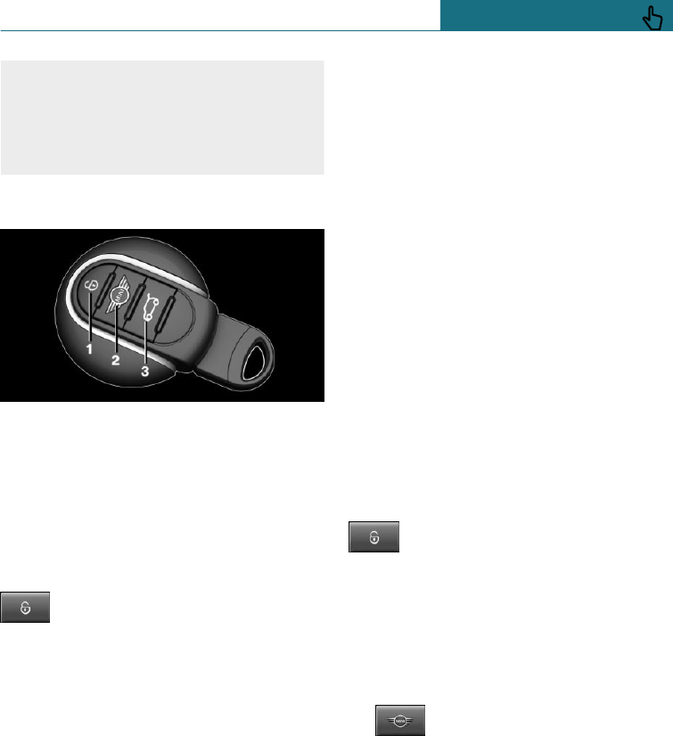
There is a risk of accidents or injury. Do
not leave children or animals unsupervised
in the vehicle. When leaving the vehicle,
take the remote control with you and lock
the vehicle.
Overview
1Unlocking
2Locking
3Unlocking the tailgate
With automatic tailgate operation: open-
ing/closing tailgate
Unlocking
Press the button on the remote con-
trol.
Depending on the settings, see page 69,
the following access points are unlocked.
–The driver's door and the fuel filler flap.
Press the button on the remote control
again to unlock the other vehicle access
points.
–All doors, the tailgate and the fuel filler
flap.
The following functions are also carried out:
–Unlocking is acknowledged by the turn
indicators. This function must be activa-
ted in the settings, see page 69.
–The settings saved in the driver profile,
see page 68, are applied.
–The driver's seat is set to the last seat
position saved. This function must be
activated in the settings, see page 69.
–The interior light, see page 146, and the
MINI logo projection are switched on,
provided that the interior light was not
switched off manually.
–Depending on the settings, the welcome
light and headlight courtesy delay fea-
ture, see page 142, are switched on.
–Exterior mirrors which were folded in
via the comfort closing feature are fol-
ded out.
–With anti-theft system: The anti-theft
system is switched off.
–The alarm system, see page 70, is
switched off.
The light functions might be dependent on
the ambient brightness.
Comfort opening
Keep the button on the remote con-
trol pressed after unlocking.
The windows and the Glass Roof are opened
for as long as the button on the remote con-
trol is pressed.
Locking
1. Close the driver's door.
2. Press the button on the remote
control.
Following functions are carried out:
–All the doors, the tailgate and fuel filler
flap are locked.
–Locking is acknowledged by the turn in-
dicators. This function must be activa-
ted in the settings, see page 69.
–With anti-theft system: The anti-theft
system is switched on. This prevents the
Seite 57
Opening and closing CONTROLS
57
Online Edition for Part no. 01402988211 - II/18
Draft
from BA-76
doors from being unlocked using the
locking buttons or the door openers.
–The alarm system, see page 70, is
switched on.
If vehicle horn sounds twice when locking,
this means engine or ignition is still
switched on. In this case, switch off engine
or ignition using start/stop button.
Comfort closing
Safety note
WARNING
Parts of the body can become trapped
when the comfort closing feature is oper-
ating. There is a danger of injury. During
comfort closing, make sure that the area of
movement is kept clear.
Closing
Keep the button on the remote con-
trol pressed after locking.
The windows and the Glass Roof are closed
for as long as the button on the remote con-
trol is pressed.
The exterior mirrors are folded in.
Switching on interior light and
courtesy light
With the vehicle locked, press the
button on the remote control.
In addition the MINI logo projection is
switched on.
These functions are not available if the inte-
rior light was switched off manually.
The light functions might be dependent on
the ambient brightness.
After locking, wait 10 seconds before press-
ing the button again.
Tailgate
General
To prevent the remote control from being
locked in, do not place the remote control in
the boot.
Depending on the equipment installed and
the country specifications, it is possible to
select whether the tailgate can be operated
with the remote control and how the vehicle
doors will respond to this. Adjust the set-
tings, see page 69.
Safety notes
WARNING
Operation of the tailgate can lead to parts
of the body becoming trapped. There is a
danger of injury. When opening and clos-
ing, make sure that the area of movement
of the tailgate is kept clear.
NOTE
The tailgate swings rearwards and up-
wards when opened. There is a danger of
damage to property. When opening and
closing, make sure that the area of move-
ment of the tailgate is kept clear.
NOTE
Sharp or angular objects can hit the rear
window and the heating conductor during
the journey. There is a danger of damage
to property. Cover the edges and make
sure that sharp objects cannot strike the
rear window.
Seite 58
CONTROLS Opening and closing
58 Online Edition for Part no. 01402988211 - II/18
Draft
from BA-76
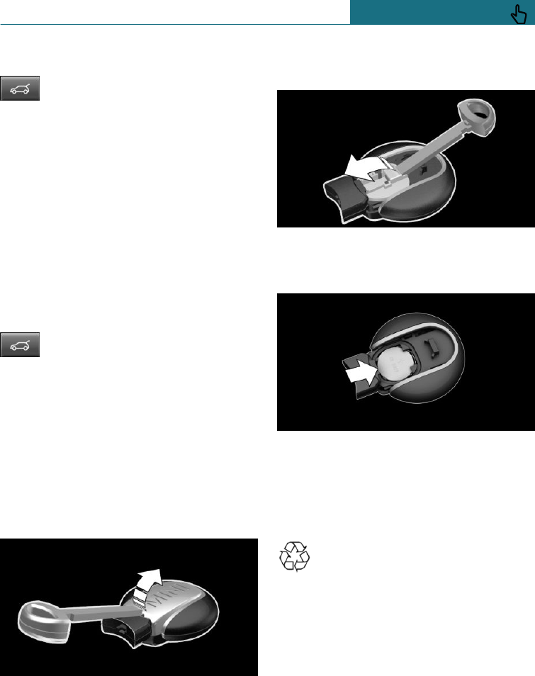
Opening
Press and hold the button on the re-
mote control for approximately
1 second.
Without automatic tailgate operation:
The tailgate is unlocked and can be swivel-
led upwards.
With automatic tailgate operation:
The tailgate is opened automatically.
When towing a trailer or using a rear lug-
gage rack, the tailgate cannot be opened
with remote control.
With automatic tailgate operation:
closing
Keep the button on the remote con-
trol pressed until the tailgate has
closed.
Releasing the button stops the movement.
Replacing the battery
1. Remove the integrated key from the re-
mote control, see page 61.
2. Push the integrated key into the open-
ing and lift the cover.
The battery compartment is accessible.
3. Push integrated key into the battery
compartment cover and raise cover.
4. Use a pointed object to push the battery
in the direction of the arrow and lift it
out.
5. Insert a new type CR 2032 battery with
the positive side facing upwards.
6. Insert lid and cover.
7. Push the integrated key into the remote
control until it snaps into place.
Dispose of old batteries at a Service
Partner of the manufacturer or an-
other qualified Service Partner or a
specialist workshop or hand them into an
authorised collecting point.
Additional remote controls
Additional remote controls are available
from a Service Partner of the manufacturer
or another qualified Service Partner or a
specialist workshop.
Seite 59
Opening and closing CONTROLS
59
Online Edition for Part no. 01402988211 - II/18
Draft
from BA-76
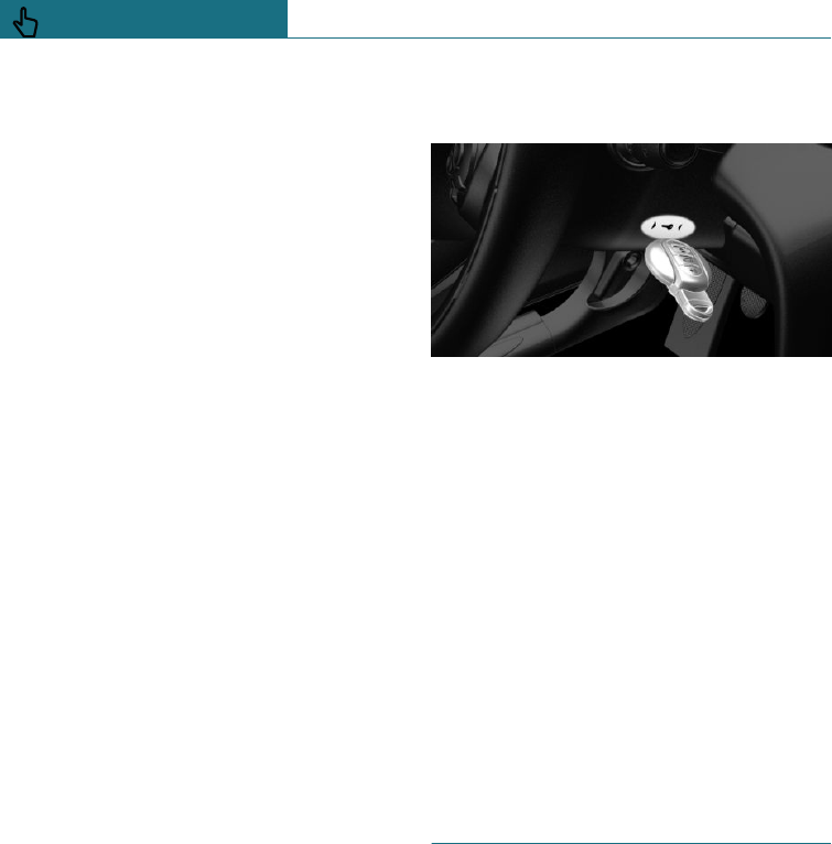
Loss of remote controls
A lost remote control can be blocked and re-
placed by a Service Partner of the manufac-
turer or another qualified Service Partner or
a specialist workshop.
Malfunction
General
A Check Control message is shown.
It may be difficult for the vehicle to detect
the remote control in some conditions, in-
cluding the following:
–The battery of the remote control is dis-
charged. Replacing the battery, see
page 59.
–Disruption of the radio link by transmis-
sion masts or other equipment transmit-
ting powerful signals.
–Shielding of the remote control by met-
allic objects.
Do not transport the remote control to-
gether with metallic objects.
–Disruption of the radio link by mobile
telephones or other electronic devices in
the immediate vicinity of the remote
control.
Do not transport the remote control to-
gether with electronic devices.
–Interference with the radio link caused
by the charging of mobile devices, for
example a mobile phone.
If there is a malfunction, the vehicle can be
unlocked and locked from the outside with
the integrated key, see page 60.
Starting the engine via special ID of
the remote control
The engine cannot be started if the remote
control has not been detected.
The drive-ready state cannot be switched on
if the remote control has not been detected.
If this happens, proceed as follows:
1. Hold the remote control against the
mark on the steering column as shown.
Pay attention to the display in the in-
strument cluster.
2. If the remote control is detected:
Start the engine within 10 seconds.
If the remote control is not detected,
change the position of the remote control
slightly and repeat the procedure.
Integrated key
General
With the integrated key, the driver's door
can be unlocked and locked without the re-
mote control.
Use the integrated key to operate the key
switch for front passenger airbags, see
page 150.
Seite 60
CONTROLS Opening and closing
60 Online Edition for Part no. 01402988211 - II/18
Draft
from BA-76
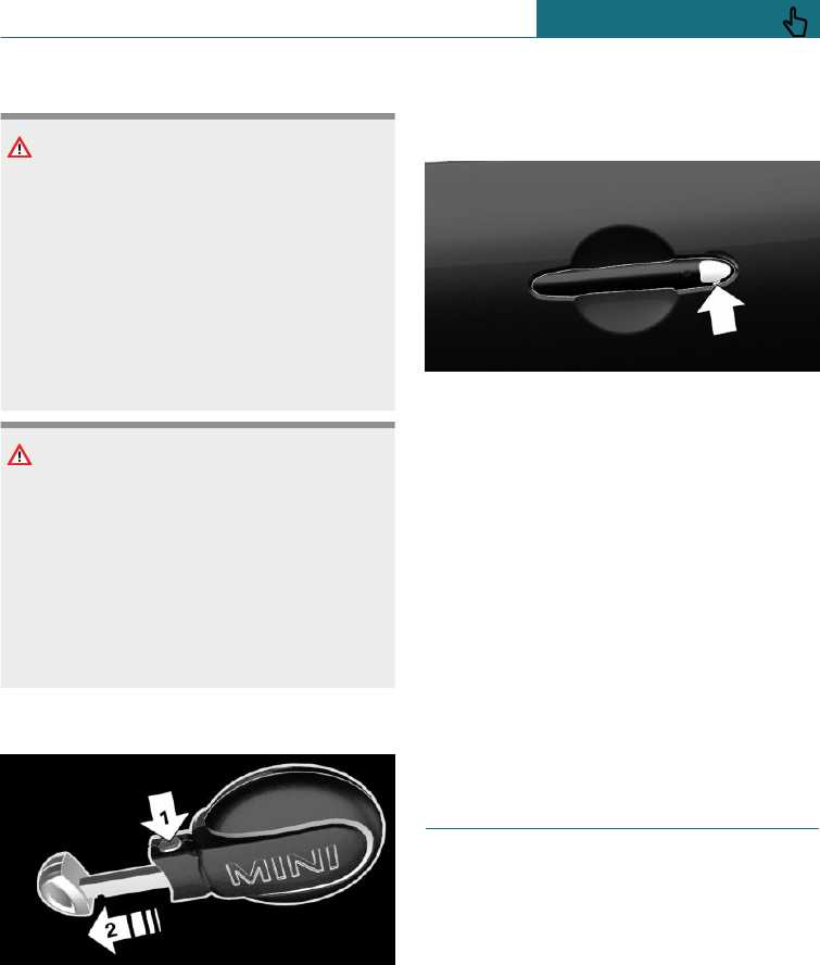
Safety notes
WARNING
For some country specifications, it is not
possible to unlock the vehicle from the in-
side if it has been locked from the outside.
There is a risk of injury or danger to life if
persons remain in the vehicle for extended
periods and are exposed to extreme tem-
peratures as a result. Do not lock the vehi-
cle from the outside when there is some-
one inside it.
NOTE
The door lock is firmly connected to the
door. The door handle can be moved. Pull-
ing the door handle when the integrated
key is inserted can damage the paint or
the integrated key. There is a danger of
damage to property. Pull out the
integrated key before pulling on the outer
door handle.
Removing
Press the button, arrow 1, and pull out the
integrated key, arrow 2.
Unlocking/locking using the door
lock
1. Remove cover on the door lock.
To do so, push the integrated key from
underneath into the opening until it
stops, and remove the cover.
2. Unlock or lock the door lock with the
integrated key.
The other doors must be unlocked or locked
from the inside.
Alarm system
The alarm system is not switched on if the
vehicle is locked with the integrated key.
Alarm system is triggered if the vehicle has
been unlocked using the door lock. To stop
the alarm, unlock the vehicle with the re-
mote control or switch on the ignition, if
necessary using the special ID feature of
the remote control, see page 60.
Central locking buttons
General
In the event of an accident of sufficient se-
verity, the vehicle is automatically un-
locked. The hazard warning lights and inte-
rior lights illuminate.
Seite 61
Opening and closing CONTROLS
61
Online Edition for Part no. 01402988211 - II/18
Draft
from BA-76
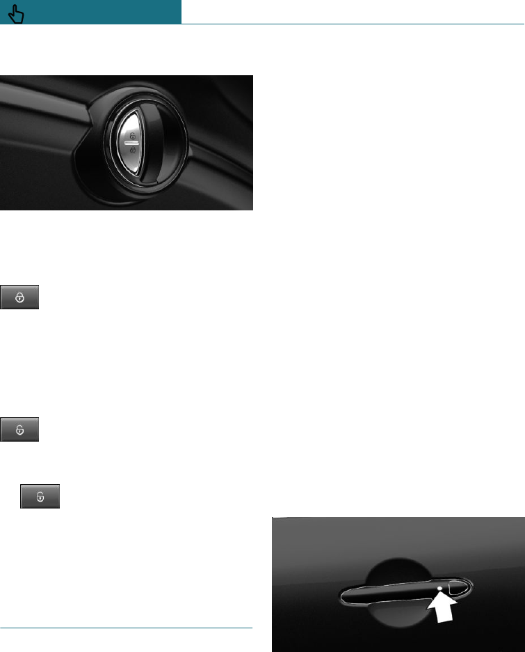
Overview
Central locking buttons.
Locking
Press the button with the front
doors closed.
–The fuel filler flap remains unlocked.
–Locking does not activate the vehicle's
anti-theft protection system.
Unlocking
Press the button.
Opening
– Press the button to unlock the
doors together and then pull the door
opener above the armrest.
–Turn the door opener on the door to be
opened. The other doors remain locked.
Comfort Access
Principle
This feature allows you to access the vehi-
cle without having to operate the remote
control.
Simply having the remote control with you,
for example in your trouser pocket, is suffi-
cient.
The vehicle automatically recognises the re-
mote control when it is in the immediate vi-
cinity or inside the vehicle.
General
Comfort Access supports the following
functions:
–Unlocking and locking the vehicle.
–Comfort closing.
–Open the tailgate.
–Opening/closing the tailgate contact-
lessly.
This function must be activated in the
settings, see page 69.
This function is unavailable in vehicles
with a trailer tow hitch or rear luggage
rack preparation.
Operating requirements
–To lock, the remote control must be lo-
cated outside the vehicle in the vicinity
of the doors.
–The vehicle can only be unlocked and
locked again after approximately 2 sec-
onds.
Unlocking
Press the button on the outer door handle of
the driver or front passenger door.
Depending on the settings, see page 69,
only the driver's door and the fuel filler flap
may be unlocked. Unlike when unlocking
Seite 62
CONTROLS Opening and closing
62 Online Edition for Part no. 01402988211 - II/18
Draft
from BA-76
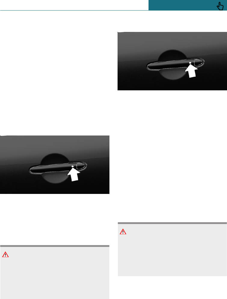
with the remote control, pressing the but-
ton on the outer door handle again does not
unlock the other vehicle access points.
Rather, the vehicle is locked again.
If a door of a locked vehicle was opened
from the inside via the door opener, press-
ing the button on the outer door handle first
locks the vehicle again. To unlock, the but-
ton on the outer door handle must be
pressed again.
This is the case whether the vehicle was
locked automatically after driving off or us-
ing the central locking button from the in-
side.
Locking
Press the button on the outer door handle of
the driver or front passenger door.
Comfort closing
Safety note
WARNING
Parts of the body can become trapped
when the comfort closing feature is oper-
ating. There is a danger of injury. During
comfort closing, make sure that the area of
movement is kept clear.
Closing
Press and hold down the button on the
outer door handle of the driver or front pas-
senger door.
In addition to locking, the windows and the
Glass Roof are closed.
The exterior mirrors are folded in.
Opening the tailgate
General
If the tailgate is opened using Comfort Ac-
cess, locked doors are not unlocked.
To prevent the remote control from being
locked in, do not place the remote control in
the boot.
Safety notes
WARNING
Operation of the tailgate can lead to parts
of the body becoming trapped. There is a
danger of injury. When opening and clos-
ing, make sure that the area of movement
of the tailgate is kept clear.
Seite 63
Opening and closing CONTROLS
63
Online Edition for Part no. 01402988211 - II/18
Draft
from BA-76
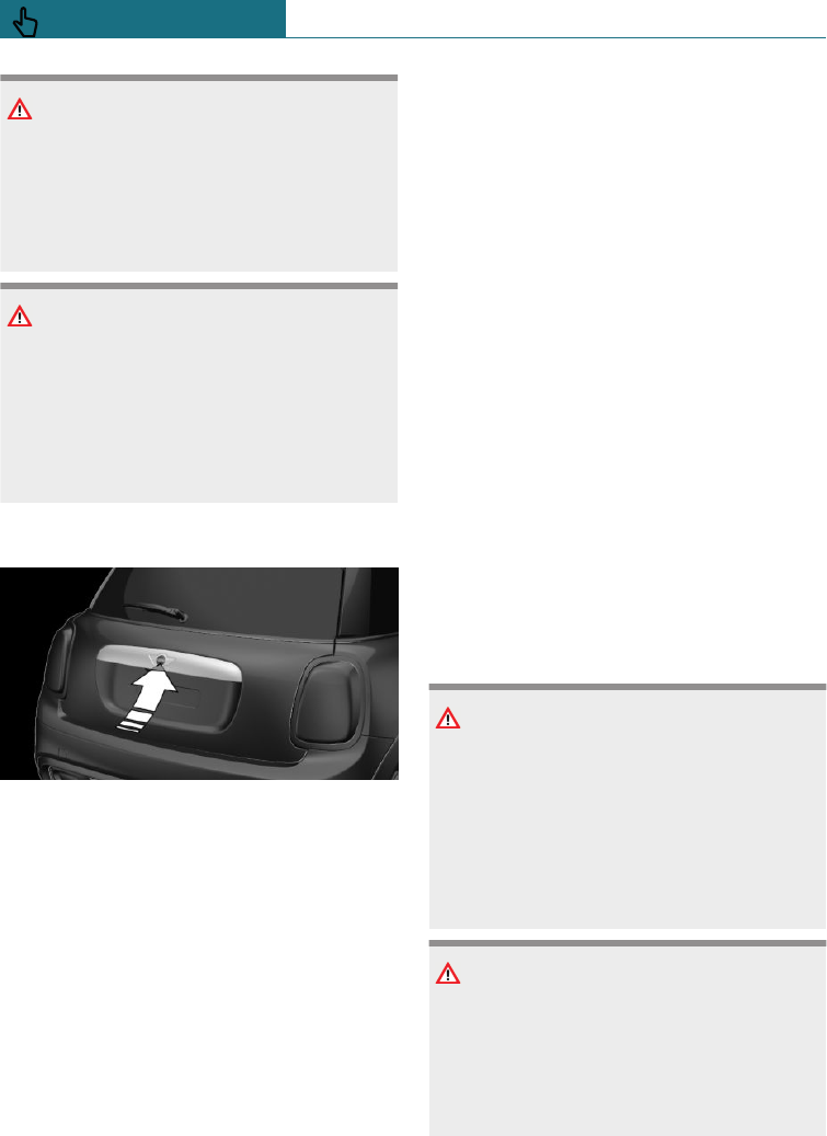
NOTE
The tailgate swings rearwards and up-
wards when opened. There is a danger of
damage to property. When opening and
closing, make sure that the area of move-
ment of the tailgate is kept clear.
NOTE
Sharp or angular objects can hit the rear
window and the heating conductor during
the journey. There is a danger of damage
to property. Cover the edges and make
sure that sharp objects cannot strike the
rear window.
Opening
Press the button on the tailgate.
Without automatic tailgate operation:
The tailgate is unlocked and can be swivel-
led upwards.
With automatic tailgate operation:
The tailgate is opened automatically.
Contactless opening and closing of
the tailgate
Principle
The tailgate can be opened and closed con-
tactlessly, provided you are carrying the re-
mote control with you. Two sensors detect a
foot movement directed forwards in the
central rear area and the tailgate is opened
or closed accordingly.
This function is unavailable in vehicles with
a trailer tow hitch or rear luggage rack
preparation.
This function must be activated in the set-
tings, see page 69.
General
To prevent the remote control from being
locked in, do not place the remote control in
the boot.
If the remote control is within the sensor
range, the tailgate can be accidentally
opened or closed by an unintentional or pre-
sumed foot movement.
The sensor range extends to approximately
1.50 m, 5 ft behind the rear area.
If the tailgate is opened with a contactless
method, locked doors are not unlocked.
Safety notes
WARNING
When operating the boot lid contactlessly,
there is a risk of touching vehicle parts,
for example the hot exhaust system. There
is a danger of injury. Make sure you are
standing securely when you perform the
foot movement, and do not touch the vehi-
cle.
WARNING
Operation of the tailgate can lead to parts
of the body becoming trapped. There is a
danger of injury. When opening and clos-
ing, make sure that the area of movement
of the tailgate is kept clear.
Seite 64
CONTROLS Opening and closing
64 Online Edition for Part no. 01402988211 - II/18
Draft
from BA-76
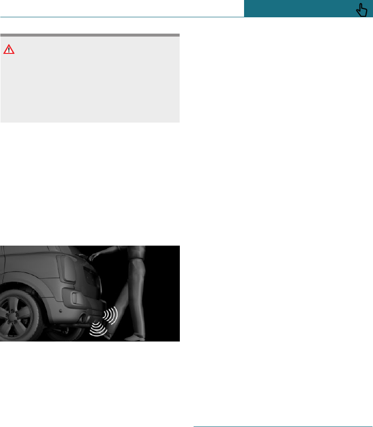
NOTE
The tailgate swings rearwards and up-
wards when opened. There is a danger of
damage to property. When opening and
closing, make sure that the area of move-
ment of the tailgate is kept clear.
Correct foot movement
1. Stand in the centre behind the vehicle,
approximately an arm's length away
from the rear of the vehicle.
2. Move a foot in the direction of travel as
far under the vehicle as possible and im-
mediately pull it back again. When per-
forming this movement, the leg must
pass through the range of both sensors.
Opening
Perform the foot movement described previ-
ously.
The hazard warning lights flash before
opening.
Moving your foot again will stop the open-
ing operation, and moving it one more time
after that will close the boot lid again.
Closing
Perform the foot movement described previ-
ously.
The hazard warning lights flash and an
acoustic signal sounds prior to closing.
Moving your foot again will stop the closing
operation, and moving it one more time af-
ter that will open the boot lid again.
Malfunction
It may be difficult for the vehicle to detect
the remote control in some conditions, in-
cluding the following:
–The battery of the remote control is dis-
charged. Replacing the battery, see
page 59.
–Disruption of the radio link by transmis-
sion masts or other equipment transmit-
ting powerful signals.
–Shielding of the remote control by met-
allic objects.
Do not transport the remote control to-
gether with metallic objects.
–Disruption of the radio link by mobile
telephones or other electronic devices in
the immediate vicinity of the remote
control.
Do not transport the remote control to-
gether with electronic devices.
Wet or snowy conditions may disrupt the
locking request recognition function on the
door handles.
If a fault occurs, unlock and lock the vehicle
with the buttons on the remote control or
with the integrated key, see page 60.
Tailgate
General
To prevent the remote control from being
locked in, do not place the remote control in
the boot.
Depending on the equipment installed and
the country specifications, it is possible to
select whether the tailgate can be operated
with the remote control and how the vehicle
Seite 65
Opening and closing CONTROLS
65
Online Edition for Part no. 01402988211 - II/18
Draft
from BA-76
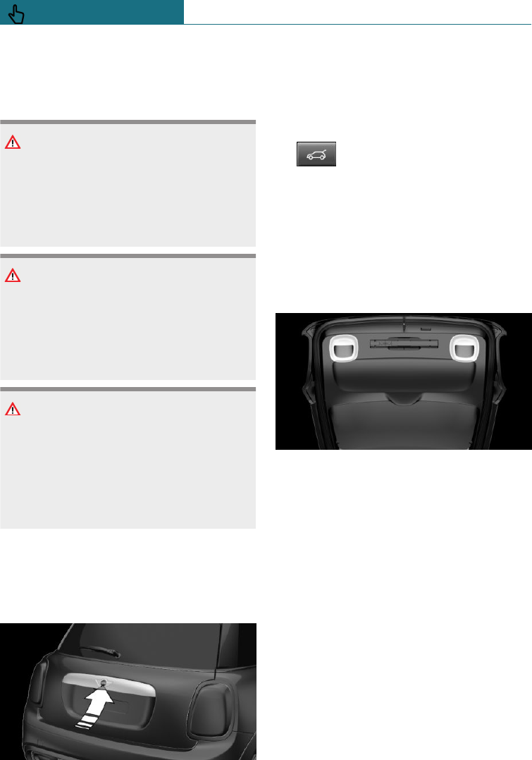
doors will respond to this. Adjust the set-
tings, see page 69.
Safety notes
WARNING
Operation of the tailgate can lead to parts
of the body becoming trapped. There is a
danger of injury. When opening and clos-
ing, make sure that the area of movement
of the tailgate is kept clear.
NOTE
The tailgate swings rearwards and up-
wards when opened. There is a danger of
damage to property. When opening and
closing, make sure that the area of move-
ment of the tailgate is kept clear.
NOTE
Sharp or angular objects can hit the rear
window and the heating conductor during
the journey. There is a danger of damage
to property. Cover the edges and make
sure that sharp objects cannot strike the
rear window.
Without automatic tailgate
operation
Opening
–Without Comfort Access: unlock vehicle.
With Comfort Access: unlock the vehi-
cle or have the remote control about
your person.
Press the button on the tailgate.
–Press and hold the button on the
remote control for approxi-
mately 1 second.
If applicable, the doors are also un-
locked. Unlocking with remote control,
see page 58.
The tailgate is unlocked and can be swivel-
led upwards.
Closing
The recessed handles in the tailgate lining
make it easier to pull the tailgate down.
With automatic tailgate operation
Opening
General
When the trailer socket is in use, the tail-
gate cannot be opened with the remote con-
trol or with the button in the interior.
To adjust the opening height
The extent to which the tailgate opens can
be set.
When setting the opening height, make
sure that there is a space of at least 10 cm,
approximately 4 in, above the tailgate.
Seite 66
CONTROLS Opening and closing
66 Online Edition for Part no. 01402988211 - II/18
Draft
from BA-76
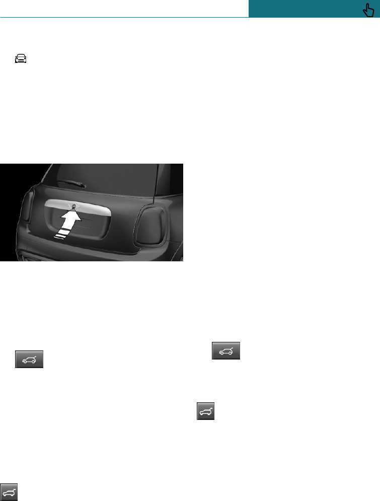
Using the on-board monitor:
1. "My MINI"
2. "Vehicle settings"
3. "Doors/Key"
4. "Tailgate"
5. Monitor the tailgate and set the desired
opening height.
From outside
–Without Comfort Access: unlock vehicle.
With Comfort Access: unlock the vehi-
cle or have the remote control about
your person.
Press the button on the outside of the
tailgate.
–Press and hold the button on the
remote control for approxi-
mately 1 second.
If applicable, the doors are also un-
locked. Unlocking with remote control,
see page 58.
When the vehicle is stationary, the tailgate
opens automatically up to the set opening
height.
From inside
Pull button in driver's door storage
compartment upwards.
When the vehicle is stationary, the tailgate
opens automatically up to the set opening
height.
Cancelling the opening operation
The opening procedure is interrupted in the
following situations:
–If the vehicle begins to move.
–By pressing the button on the outside of
the tailgate. Pressing again closes the
tailgate.
–By pressing the button on the inside of
the tailgate. Pressing again closes the
tailgate.
–By pressing the button on the remote
control. Pressing the button again re-
sumes the opening operation.
Pressing and holding the button closes
the tailgate again.
–By pressing or pulling the button in the
storage compartment of the driver's
door. Pulling again resumes the opening
operation.
Closing
From outside
–Press the button on the outside of the
tailgate.
–Keep the button on the remote
control pressed until the tailgate
has closed.
From inside
Press and hold the button in the driv-
er's door storage compartment.
For this function, the remote control must
be in the passenger compartment.
From inside of the tailgate
Without Comfort Access:
Seite 67
Opening and closing CONTROLS
67
Online Edition for Part no. 01402988211 - II/18
Draft
from BA-76
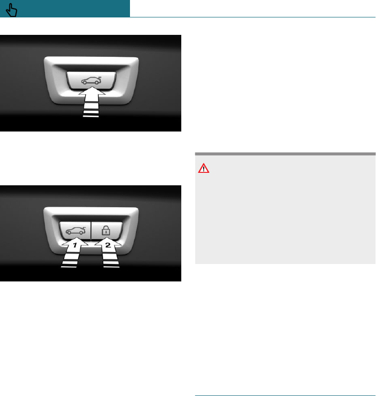
Press the button on the inside of the tail-
gate.
With Comfort Access:
–Press the button on the inside of the
tailgate, arrow 1.
–Press the button, arrow 2.
The vehicle is locked after the tailgate
has been closed. To do this, the driver's
door must be closed and the remote con-
trol must be outside the vehicle in the
vicinity of the tailgate.
Cancelling the closing operation
The closing procedure is interrupted in the
following situations:
–When driving off suddenly.
–By pressing the button on the outside of
the tailgate. Pressing again closes the
tailgate.
–By pressing the button on the inside of
the tailgate. Pressing again closes the
tailgate.
–By releasing the button in the driver's
door storage compartment. Pressing the
button again and holding it down re-
sumes the closing operation.
–By releasing the button on the remote
control. Pressing the button again and
holding it down resumes the closing op-
eration.
Malfunction
Safety note
WARNING
A locked tailgate can unexpectedly move
during manual operation. There is a dan-
ger of injury or damage to property. Do not
manually operate a locked tailgate. Have a
check performed by a Service Partner of
the manufacturer or another qualified
Service Partner or a specialist workshop.
Manual operation
When operating the unlocked tailgate man-
ually, do so slowly and without a sudden
movement.
Only light pressure is required to fully close
the tailgate. The closing operation is then
performed automatically.
Driver profiles
Principle
Individual settings for several drivers can
be saved in the driver profiles and called up
again as required.
General
Three profiles are provided, in which per-
sonal vehicle settings can be saved. Each re-
mote control is allocated to one of these
driver profiles.
Seite 68
CONTROLS Opening and closing
68 Online Edition for Part no. 01402988211 - II/18
Draft
from BA-76

When the vehicle is unlocked with a remote
control, the allocated driver profile is activa-
ted. All the settings saved in the driver pro-
file are applied automatically.
If several drivers each use their own remote
control, the vehicle will adapt to their per-
sonal settings when it is unlocked. These
settings are also restored if the vehicle is
used in the intervening period by someone
with a different remote control.
Changes to settings are saved automatically
in the currently used driver profile.
Operating requirements
To ensure that the correct driver profile can
be set, the system must be able to assign
the detected remote control uniquely to the
driver.
This is assured if the following conditions
are met:
–The driver is only carrying their own re-
mote control.
–The driver unlocks the vehicle.
–The driver enters the vehicle through
the driver's door.
Settings
Settings for the following systems and func-
tions are saved in the active profile. Which
settings can be saved depends on the coun-
try and equipment.
–Unlocking and locking.
–Lights.
–Radio.
–Instrument cluster.
–Favourites buttons.
–Volumes, sound.
–Control Display.
–Air conditioning.
–Park Distance Control PDC.
–Rear-view camera.
–MINI Driving Modes.
–Intelligent Safety.
–Driver's seat position, exterior mirror
position.
The positions set via the seat memory
and the last position set are saved.
System limits
It is not always possible to assign a remote
control uniquely to a driver. This may be the
case in the following scenarios:
–The front passenger unlocks the vehicle
with their remote control, but another
person drives.
–The driver unlocks the vehicle using
Comfort Access and is carrying a num-
ber of remote controls.
–If there is a change of driver without the
vehicle being locked and unlocked.
–If a number of remote controls are loca-
ted in the area outside of the vehicle.
Settings
General
Various settings are possible for opening
and closing, depending on the equipment
installed and the country specifications.
These settings are saved for the currently
used driver profile, see page 68.
Unlocking
Doors
Using the on-board monitor:
1. "My MINI"
2. "Vehicle settings"
3. "Doors/Key"
Seite 69
Opening and closing CONTROLS
69
Online Edition for Part no. 01402988211 - II/18
Draft
from BA-76

4. "Driver's door" or "All doors"
5. Select the desired setting:
–"Driver's door only"
Only the driver's door and fuel filler
flap are unlocked. Pressing again un-
locks the entire vehicle.
–"All doors"
The entire vehicle is unlocked.
Tailgate
Using the on-board monitor:
1. "My MINI"
2. "Vehicle settings"
3. "Doors/Key"
4. "Tailgate" or "Tailgate and door(s)"
5. Select the desired setting:
–"Tailgate"
Depending on equipment, tailgate is
unlocked or opened.
–"Tailgate and door(s)"
Depending on equipment, tailgate is
unlocked or opened and doors are
unlocked.
Depending on the equipment installed and
the country specifications, these settings
may not be available.
Automatic locking
Using the on-board monitor:
1. "My MINI"
2. "Vehicle settings"
3. "Doors/Key"
4. Select the desired setting:
–"Relock automatically"
The vehicle is automatically locked
again after a short while if no door is
opened after unlocking.
–"Lock after pulling away"
On driving off, the vehicle is locked
automatically.
Automatic unlocking
Using the on-board monitor:
1. "My MINI"
2. "Vehicle settings"
3. "Doors/Key"
4. "Unlock at end of journey"
After the engine is switched off by
pressing the start/stop button, the
locked vehicle is unlocked automati-
cally.
Acknowledgement signals of the
vehicle
Using the on-board monitor:
1. "My MINI"
2. "Vehicle settings"
3. "Doors/Key"
4. "Flash for lock/unlock"
Unlocking is acknowledged by flashing
twice, locking by flashing once.
Alarm system
General
The alarm system responds to the following
changes when the vehicle is locked:
–Unauthorised opening of a door, the
bonnet or the tailgate.
–There are movements inside the vehicle.
–The vehicle's incline changes, for in-
stance if an attempt is made to jack it up
and steal the wheels or to raise it prior
to towing away.
–There is an interruption in the power
supply from the battery.
Seite 70
CONTROLS Opening and closing
70 Online Edition for Part no. 01402988211 - II/18
Draft
from BA-76
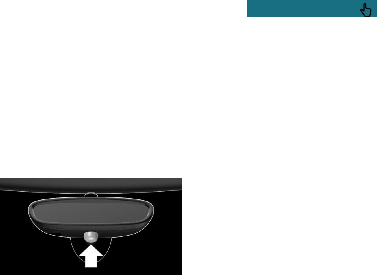
–Improper use of the socket for on-board
diagnosis.
The alarm system indicates these changes
visually and audibly:
–Audible alarm:
Depending on local regulations, the
acoustic alarm may be suppressed.
–Visual alarm:
By flashing the exterior lights.
Overview
Indicator lamp on the rearview mirror.
Switching on/off
The alarm system is switched on and off at
the same time as the vehicle is unlocked
and locked via the remote control or Com-
fort Access.
Opening the doors when the alarm
system is switched on
The alarm system is triggered on opening a
door if the door has been unlocked using
the integrated key in the door lock.
Stopping the alarm, see page 72.
Opening the tailgate with the alarm
system switched on
The tailgate can be opened even with the
alarm system switched on.
On closing the tailgate, it is locked again
and monitored, as long as the doors are
locked. The hazard warning lights flash
once.
Signals of the indicator lamps
–Indicator lamp flashes every 2 seconds:
The alarm system is switched on.
–Indicator lamp flashes for approximately
10 seconds before it flashes every 2 sec-
onds:
Interior movement detector and tilt
alarm sensor are not active because
doors, bonnet or tailgate are not closed
correctly. Correctly closed access points
are secured.
If the open access points are then
closed, the interior protection and tilt
alarm sensor are switched on.
–The indicator lamp extinguishes after
the vehicle has been unlocked:
No attempt has been made to tamper
with the vehicle.
–The indicator lamp flashes after unlock-
ing until the ignition is switched on, but
for no longer than approximately 5 mi-
nutes:
The alarm has been triggered.
Tilt alarm sensor
The incline of the vehicle is monitored.
The alarm system responds, for example,
when there is an attempt to steel a wheel or
when towing away.
Interior movement detector
To ensure perfect functioning, the windows
and Glass Roof must be closed.
Seite 71
Opening and closing CONTROLS
71
Online Edition for Part no. 01402988211 - II/18
Draft
from BA-76
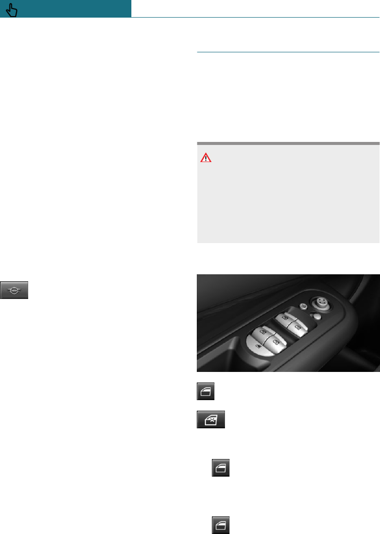
Avoiding false alarms
General
The tilt alarm sensor and the interior move-
ment detector may trigger an alarm without
any unauthorised activity taking place.
Possible situations for an unwanted alarm:
–In washing bays or car washes.
–In two-level garages.
–During transport via motorail, car ferry
or trailer.
–When there are animals in the vehicle.
–At the filling station: if the vehicle is
locked after refuelling starts.
The tilt alarm sensor and interior protection
can be switched off for such situations.
Switching off the tilt alarm sensor and
interior movement detector
Within 10 seconds of locking the
vehicle, press the button on the re-
mote control again.
The indicator lamp illuminates for approxi-
mately 2 seconds and then flashes again.
The tilt alarm sensor and the interior move-
ment detector are switched off until the
next time the vehicle is locked.
Stopping the alarm
–Unlock the vehicle with the remote con-
trol or switch on the ignition, if neces-
sary using the special ID feature of the
remote control, see page 60.
–With Comfort Access: if you are carry-
ing the remote control with you, unlock
the vehicle via the button in the driver
or front passenger door.
Power window switches
General
In an accident of corresponding severity,
the windows are automatically closed until
only a small gap remains.
Safety note
WARNING
Parts of the body can become trapped
when the windows are operating. There is
a danger of injury or damage to property.
When opening and closing, make sure that
the area of movement of the windows is
kept clear.
Overview
Power window switches.
Safety switch.
Opening
– Push the switch as far as the re-
sistance point.
The window opens as long as the switch
is held.
– Push the switch past the resistance
point.
Seite 72
CONTROLS Opening and closing
72 Online Edition for Part no. 01402988211 - II/18
Draft
from BA-76
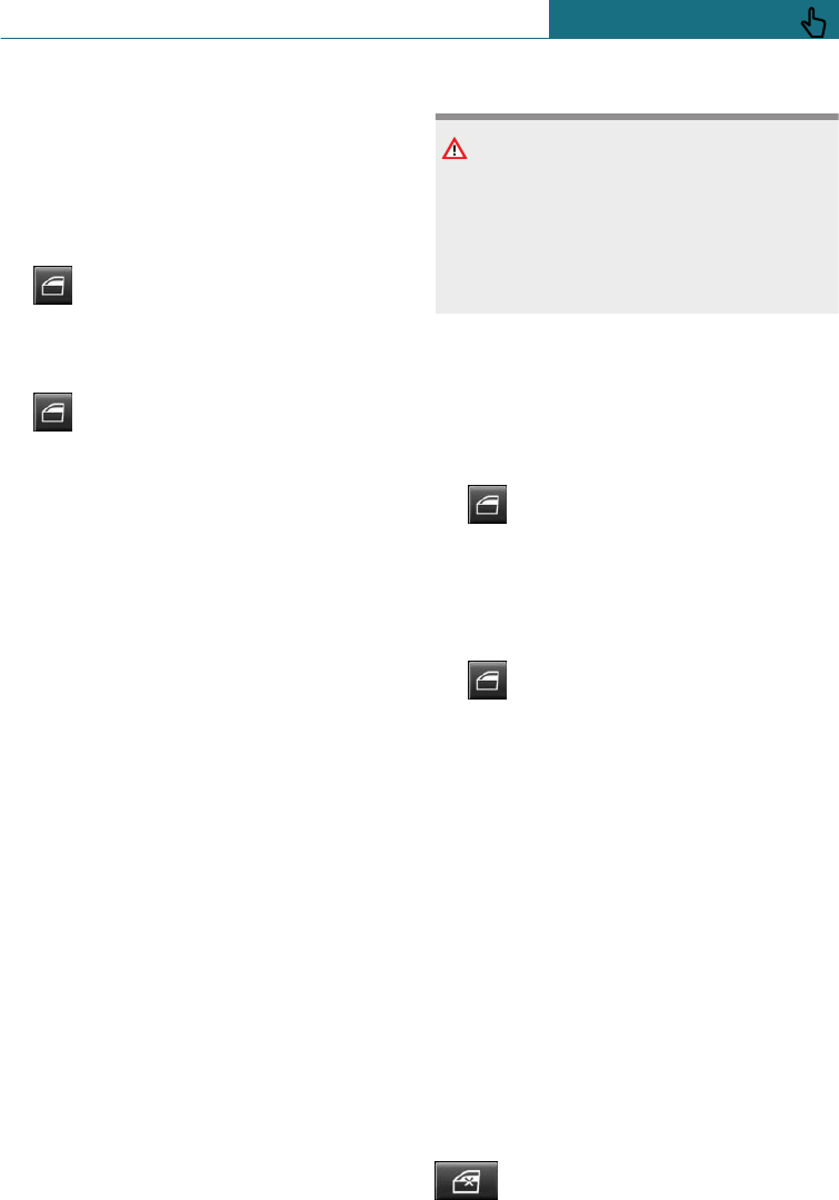
The window is opened automatically.
The movement is stopped by pressing
the switch again.
Comfort opening using the remote control,
see page 57.
Closing
– Pull the switch as far as the resist-
ance point.
The window closes as long as the switch
is held.
– Pull the switch past the resistance
point.
The window closes automatically if the
door is closed. The movement is stopped
by pulling the switch again.
Comfort closing using the remote control,
see page 58.
Closing using Comfort Access, see page 63.
After switching off the ignition
Windows can still be operated:
–For an extended period of time if radio
ready state is switched on.
–For approximately 1 minute with the ig-
nition switched off.
Anti-trap mechanism
General
If the closing force exceeds a certain value
when one of the front windows is closing,
the closing operation is interrupted.
The window is opened slightly.
Safety note
WARNING
Accessories on the windows, for example
aerials, can impair the anti-trap mecha-
nism. There is a danger of injury. Do not
attach any accessories in the area of move-
ment of the windows.
Closing without the anti-trap
mechanism
If an external danger or ice does not allow
you to close the windows normally, proceed
as follows:
1. Pull the switch past the resistance
point and hold it there.
The window is closed with a restricted
anti-trap mechanism. If the closing force
exceeds a certain value, the closing op-
eration is interrupted.
2. Pull the switch past the resistance
point again within approximately 4 sec-
onds and hold it there.
The window is closed without the anti-
trap mechanism.
Safety switch
General
The safety switch can be used to prevent
children from opening and closing the rear
windows by means of the switches in the
rear, for example.
In the event of an accident of sufficient se-
verity, the safety function is automatically
switched off.
Switching on/off
Press the button.
Seite 73
Opening and closing CONTROLS
73
Online Edition for Part no. 01402988211 - II/18
Draft
from BA-76
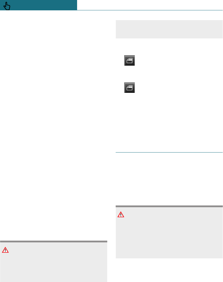
The LED is illuminated when the safety
function is switched on.
Malfunction
General
In certain cases, it is possible that the win-
dow functions may be limited.
–The window functions may be limited
after a power cut during the opening or
closing operation. In this case, the sys-
tem must be initialised.
–The power window motors are equipped
with overheating protection. If a win-
dow is opened and closed repeatedly
within a short period of time, the over-
heating protection switches off the mo-
tor temporarily. It will only be possible
to close the window, or possibly no lon-
ger operate it at all, depending on the
degree of overheating.
In this case: allow the power window
motor to cool down.
Initialising the system
The system can be initialised when the ve-
hicle is stationary and the engine is run-
ning.
During the initialisation, the window con-
cerned closes without the anti-trap mecha-
nism.
WARNING
Parts of the body can become trapped
when the windows are operating. There is
a danger of injury or damage to property.
When opening and closing, make sure that
the area of movement of the windows is
kept clear.
1. Open the window in question com-
pletely.
2. Pull the switch as far as the resist-
ance point and hold it there.
The window is closed.
3. Continue to hold the switch pulled
as far as the resistance point.
After approximately 15 seconds, the
window opens and closes once or twice,
depending on the fitted equipment.
4. Release the switch.
Panorama Glass Roof
General
In the event of an accident of sufficient se-
verity, the glass roof is automatically un-
locked.
Safety note
WARNING
Parts of the body may become trapped
when the Glass Roof is operating. There is
a danger of injury. When opening and
closing, make sure that the area of move-
ment of the Glass Roof is kept clear.
Seite 74
CONTROLS Opening and closing
74 Online Edition for Part no. 01402988211 - II/18
Draft
from BA-76
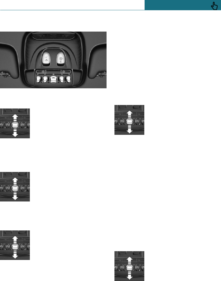
Overview
Raising the Glass Roof
Push the switch back to resist-
ance point or beyond it and re-
lease.
Glass Roof is raised.
Opening the Glass Roof
With the Glass Roof closed
Press the switch twice back
past the resistance point and
release.
Glass Roof is opened.
The movement is stopped by
pressing the switch again.
With Glass Roof raised
–Press the switch to the
rear to the pressure point
and hold.
The Glass Roof opens as
long as the switch is
pressed.
–Push the switch back past the resistance
point and release.
Glass Roof is opened.
The movement is stopped by pressing
the switch again.
Comfort position
In some models, the wind noises in the car's
interior are lowest when the glass roof is
not fully open. In these models, the auto-
matic function initially only opens the glass
roof as far as this comfort position.
Pressing the switch again opens the glass
roof fully.
Closing the Glass Roof
With Glass Roof open
–Press the switch to the
front to the pressure point
and hold.
The Glass Roof is closed as
long as the switch is
pressed and stops in the
raised position.
–Push the switch forward past the resist-
ance point and release.
The Glass Roof is closed and stops in the
raised position.
The movement is stopped by pressing
the switch again.
–Push the switch twice forward past the
resistance point and release.
The Glass Roof is closed.
The movement is stopped by pressing
the switch again.
With Glass Roof raised
Push the switch forward past
the resistance point and re-
lease.
The Glass Roof is closed.
After switching off the ignition
The Glass Roof can still be opened or closed
for approximately 1 minute after the igni-
tion has been switched off.
Seite 75
Opening and closing CONTROLS
75
Online Edition for Part no. 01402988211 - II/18
Draft
from BA-76

Anti-trap mechanism
General
If the closing power of the Glass Roof ex-
ceeds a certain value, the closing operation
is interrupted.
The Glass Roof is opened slightly.
Closing without the anti-trap
mechanism
In the event of danger from the outside,
proceed as follows:
1. Push the switch forward past the resist-
ance point and hold.
The Glass Roof is closed with a restric-
ted anti-trap mechanism. If the closing
force exceeds a certain value, the clos-
ing operation is interrupted.
2. Press the switch forwards once again
beyond the resistance point and hold un-
til the Glass Roof closes without the
anti-trap mechanism. Ensure that the
closing area is clear.
Initialising after a power failure
If a power failure occurs while the Glass
Roof is opening or closing, it may only have
limited functionality afterwards. In this
case, the system must be initialised. MINI
recommends having this work carried out
by a Service Partner of the manufacturer or
another qualified Service Partner or a spe-
cialist workshop.
Seite 76
CONTROLS Opening and closing
76 Online Edition for Part no. 01402988211 - II/18
Draft
from BA-76
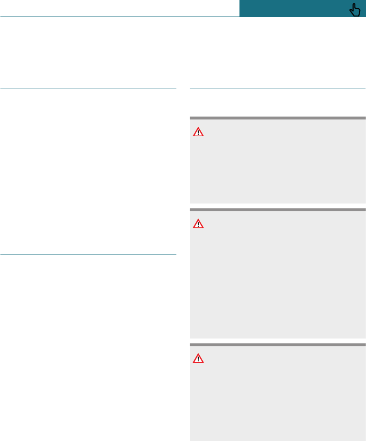
Seats, mirrors and steering wheel
Vehicle equipment
This chapter describes all standard, country-
specific and special equipment available for
the model series. Therefore equipment
which is not installed in your vehicle, for
example on account of the optional equip-
ment selected or the country specification,
may also be described here. This also ap-
plies to safety-relevant functions and sys-
tems. Comply with the relevant laws and
regulations when using the corresponding
functions and systems.
Safe seating position
A seating position that suitably reflects the
requirements of the occupants is essential
for relaxed driving with minimum fatigue.
In an accident, the correct seating position
plays an important role. Comply with the
notes in the following chapters:
–Seats, see page 77.
–Seat belts, see page 81.
–Head restraints, see page 85.
–Airbags, see page 148.
Front seats
Safety notes
WARNING
To adjust the seat during a journey could
cause the seat to move unexpectedly. You
could lose control of the vehicle. There is a
danger of accidents. Only adjust the seat
on the driver's side when at a standstill.
WARNING
If the seat backrest is angled back too far,
the protective effect of the seat belt will
no longer be guaranteed. There is a danger
of sliding under the seat belt in the event
of an accident. There is a danger of injury
or even death. Adjust the seat before start-
ing the journey. Adjust the seat backrest
to the most upright position possible, and
do not change it during the journey.
WARNING
There is a risk of entrapment when the
seats are being moved. There is a danger
of injury or damage to property. Before
making any adjustment, make sure that
the area of movement of the seat is kept
clear.
Seite 77
Seats, mirrors and steering wheel CONTROLS
77
Online Edition for Part no. 01402988211 - II/18
Draft
from BA-76
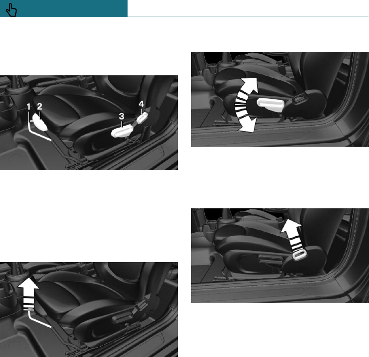
Manually adjustable seats
Overview
1Forward/back
2Thigh support
3Height
4Backrest angle
Forward/back
Pull the lever and slide the seat in the de-
sired direction.
After releasing the lever, move the seat gen-
tly forward or back to make sure it engages
properly.
Height
Pull the lever up or press the lever down un-
til the desired height is reached.
Backrest angle
Pull the lever and add or remove pressure
on the backrest as required.
Lumbar support
The curvature of the backrest can be
changed in such a way that the lumbar re-
gion, the lordosis, is supported. The upper
edge of the pelvis and the spinal column are
supported to encourage an upright posture.
Seite 78
CONTROLS Seats, mirrors and steering wheel
78 Online Edition for Part no. 01402988211 - II/18
Draft
from BA-76
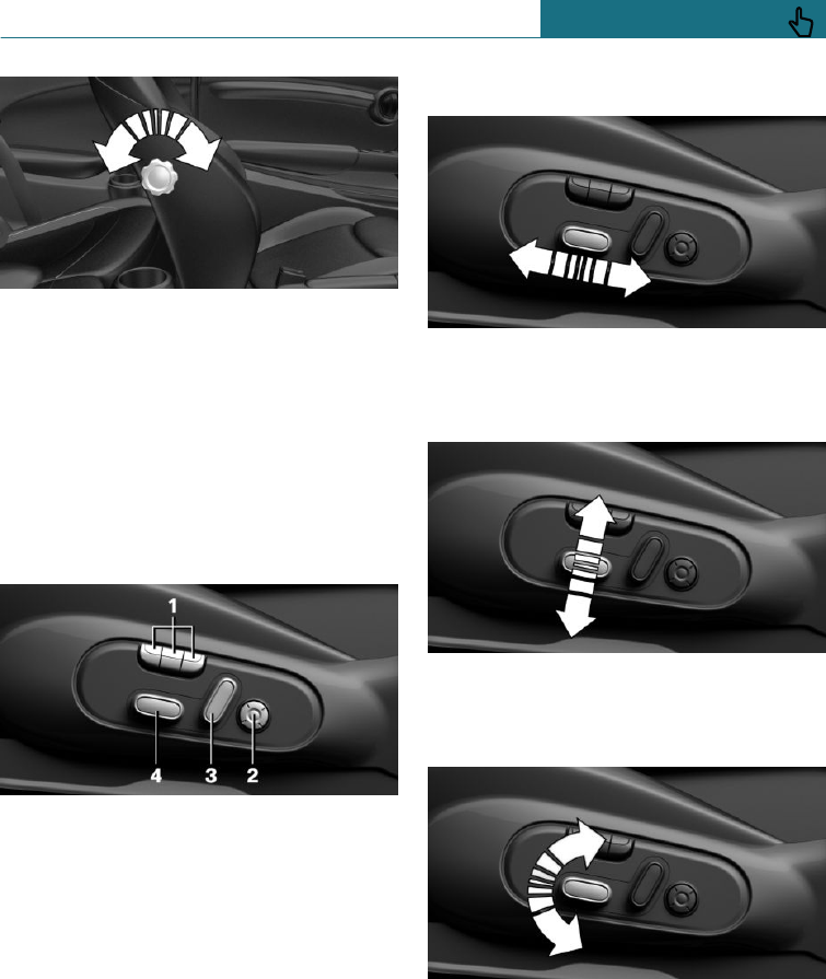
Turn the wheel to increase or decrease the
curvature.
Electrically adjustable seats
General
The current seat position can be saved with
the memory function, see page 87.
Overview
1Memory function
2Lumbar support
3Backrest angle
4Forward/back, height, seat angle
Forward/back
Press the switch forwards or backwards.
Height
Press the switch up or down.
Seat angle
Tilt the switch up or down.
Seite 79
Seats, mirrors and steering wheel CONTROLS
79
Online Edition for Part no. 01402988211 - II/18
Draft
from BA-76
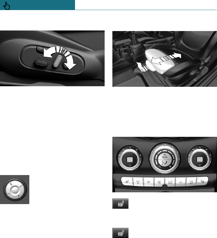
Backrest angle
Tilt the switch forwards or backwards.
Lumbar support
Principle
The curvature of the backrest can be
changed in such a way that the lumbar re-
gion, the lordosis, is supported. The upper
edge of the pelvis and the spinal column are
supported to encourage an upright posture.
To adjust
–Press the button at the
front/rear:
The curvature is in-
creased/decreased.
–Press the button at the
top/bottom:
The curvature is shifted
upwards/downwards.
Thigh support
Pull the lever on the front of the seat and
adjust the thigh support.
Seat heating, front
Overview
Seat heating
Switching on
Press the button once for each tem-
perature level.
The maximum temperature is selected if the
three LEDs are illuminated.
If the journey is continued within about
15 minutes after a temporary stop, the seat
heating is automatically activated with the
last temperature set.
If GREEN Mode is activated, see page 238,
the heating power is reduced.
Seite 80
CONTROLS Seats, mirrors and steering wheel
80 Online Edition for Part no. 01402988211 - II/18
Draft
from BA-76
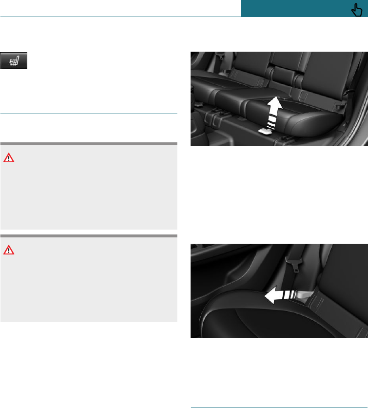
Switching off
Press and hold the button until the
LEDs are extinguished.
Rear seats
Safety notes
WARNING
There is a risk of entrapment when folding
down the centre armrest in the rear. There
is a danger of injury. When folding down,
make sure that the area of movement of
the centre armrest is kept clear.
WARNING
The backrest can unexpectedly move dur-
ing the journey as a result of being unin-
tentionally unlocked via the loops. There is
a danger of injury. Do not attach objects to
the loops for unlocking the rear backrests.
Forward/back
General
The rear backrest is split 60–40. The left-
hand seat is connected to the middle part.
To adjust
Pull the lever and slide the seat in the de-
sired direction.
After releasing the lever, move the seat gen-
tly forward or back to make sure it engages
properly.
Backrest angle
Pull loop and add or remove pressure on
backrest as required.
Seat belts
Number of seat belts and belt
buckles
For the safety of the vehicle occupants, the
vehicle is equipped with five seat belts.
However, they can only provide effective
protection when worn correctly.
The two outer belt buckles in the rear seat
are intended for those sitting on the left and
right.
Seite 81
Seats, mirrors and steering wheel CONTROLS
81
Online Edition for Part no. 01402988211 - II/18
Draft
from BA-76

The inner belt buckle of the rear seat is in-
tended for the person sitting in the middle.
General
Before a journey, always make sure that all
occupants have fastened their seat belts.
The airbags are a complementary safety fea-
ture and not a substitute for the seat belts.
Unhook seat belt in rear from the side belt
holder if necessary.
The belt anchorage is suitable for adults of
any stature if the seat is adjusted correctly.
Safety notes
WARNING
Never restrain more than one person with
each seat belt, otherwise the protective ef-
fect of the seat belt is no longer guaran-
teed. There is a danger of injury or even
death. Only restrain one person with each
seat belt. Do not allow infants and children
to travel on the lap of another occupant.
Instead, secure the infant or child in a
child restraint system intended for this
purpose.
WARNING
The protective function of the seat belts
may be limited or may even fail completely
if the seat belts are worn incorrectly. If a
seat belt is not worn correctly, additional
injuries can be caused, for example in the
event of an accident or braking and eva-
sive manoeuvres. There is a danger of in-
jury or even death. Make sure that all vehi-
cle occupants have fastened their seat
belts correctly.
WARNING
Seat belts are designed to bear upon the
body's skeleton and should be worn low
across the front of the pelvis, or lie against
pelvis, chest and shoulders, as applicable.
Do not route the lap section of the belt
across the abdomen.
Seat belts should be adjusted as firmly as
possible, consistent with comfort, to pro-
vide the protection for which they have
been designed. A slack belt will greatly re-
duce the protection afforded to the wearer.
Do not allow the seat belt webbing to
come into contact with polishes, oils and
chemicals and particularly battery acid. It
may be safely cleaned with a mild soap wa-
ter solution. Replace the seat belt if the
webbing becomes frayed, contaminated or
damaged. Seat belts should not be worn
with seat belt straps twisted. Each seat
belt assembly must only be used by one
occupant; carrying infants and children on
the occupant's lap is not permitted.
It is essential to replace the entire assem-
bly after it has been worn in a severe im-
pact even if damage to the assembly is not
obvious.
WARNING
No modifications or additions should be
made by the user that will either prevent
the seat belt adjusting devices from oper-
ating to remove slack, or prevent the seat
belt assembly from being adjusted to re-
move slack.
WARNING
The protective function of the seat belts
may be limited or may even fail completely
in the following situations:
Seite 82
CONTROLS Seats, mirrors and steering wheel
82 Online Edition for Part no. 01402988211 - II/18
Draft
from BA-76
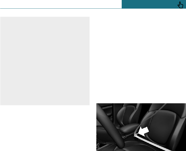
–The seat belts or belt buckles are
damaged, dirty or have been modified
in another way.
–Belt tensioners or belt retractors have
been modified.
Seat belts can be damaged in an accident
without the damage necessarily being ap-
parent. There is a danger of injury or even
death. Do not modify seat belts, belt buck-
les, belt tensioners, belt retractors and belt
anchor points and ensure that they are
kept clean. After an accident, have the seat
belts inspected at a Service Partner of the
manufacturer or another qualified Service
Partner or a specialist workshop.
Correct seat belt use
–Place the seat belt tightly over the pelvis
and shoulder, close to the body and
without twisting.
–Make sure that the seat belt is posi-
tioned low at the hip in the area of the
pelvis. The seat belt must not press on
the abdomen.
–The seat belt must not be rubbed on
sharp edges, be routed over solid or
breakable objects or be trapped.
–Avoid bulky clothing.
–Keep the seat belt taut by occasionally
pulling upwards on the upper section.
Adjustment for automatic
retracting seat belts
–Pull the seat belt tongue diagonally
across the body and push it into the belt
buckle until it audibly engages into
place.
–It is important to adjust the belt length
correctly. To adjust the lap belt and
check whether the belt tongue has en-
gaged correctly in the buckle, pull up-
wards on the shoulder section of the
belt until the lap belt fits tightly.
–The diagonal shoulder strap adjusts au-
tomatically to allow freedom of move-
ment.
–To release the seat belt, press the button
on the buckle.
Fastening the seat belt
1. When fastening the seat belt, guide the
seat belt slowly from the bracket.
2. Insert the seat belt tongue in the belt
buckle. The seat belt buckle must be
heard to engage.
Unfastening the seat belt
1. Hold the seat belt firmly.
2. Press the red button on the belt buckle.
3. Guide the seat belt back up to the reel
mechanism.
Seite 83
Seats, mirrors and steering wheel CONTROLS
83
Online Edition for Part no. 01402988211 - II/18
Draft
from BA-76
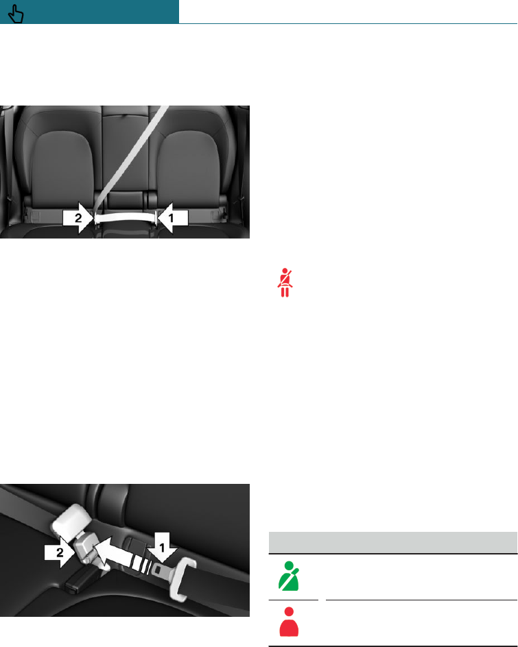
Middle seat belt in the rear
Fastening the seat belt
1. Pull the seat belt tongues out of the
holder in the roof.
2. Insert the lower seat belt tongue in the
belt lock, arrow 1.
3. Insert upper seat belt tongue in belt
lock, arrow 2.
Belt locks must engage audibly.
Unfastening the seat belt
1. Hold the seat belt firmly.
2. Press the red button on the belt buckle.
3. Use the seat belt tongue, arrow 1, to
open the second belt buckle, arrow 2.
4. Guide seat belt to bracket in roof lining.
Seat belt reminder for driver and
front passenger seat
General
The seat belt reminder is activated when
the seat belt on the driver's side is not fas-
tened. For some country specifications, the
seat belt reminder is also active if the front
passenger seat belt is not fastened and
heavy objects are on the front passenger
seat.
Display in the instrument cluster
A Check Control message is shown.
Check whether the seat belt has
been fastened correctly.
Seat belt reminder for rear seats
General
The seat belt reminder is automatically acti-
vated every time the engine starts.
The seat belt reminder will also be activated
if a rear seat belt is unfastened during the
journey.
Display in the instrument cluster
The indicator lamp in the instrument cluster
is illuminated after the engine starts.
Symbol Description
Green: seat belt fastened on the
corresponding rear seat.
Red: seat belt not fastened on
the corresponding rear seat.
Seite 84
CONTROLS Seats, mirrors and steering wheel
84 Online Edition for Part no. 01402988211 - II/18
Draft
from BA-76
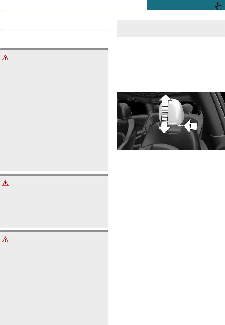
Front head restraints
Safety notes
WARNING
If the head restraints are removed or in-
correctly adjusted, they cannot provide
protection as intended and head and neck
injuries may result. There is a danger of
injury.
–Before a journey, re-install any re-
moved head restraints on all occupied
seats.
–Adjust the head restraint so its centre
supports the back of the head at as
close to eye level as possible.
–Adjust the distance so that the head
restraint is as close as possible to the
back of the head. Set the distance via
the backrest tilt as needed.
WARNING
Parts of the body can become trapped
when the head restraints are moving.
There is a danger of injury. When moving
the head restraint, make sure that the area
of movement is kept clear.
WARNING
Objects on the head restraint reduce the
protective effect in the head and neck
area. There is a danger of injury.
–Do not fit any covers on the seats or
head restraints.
–Do not hang objects such as coat
hangers directly on the head re-
straint.
–Only use accessories that have been
classified as safe for attaching to the
head restraint.
–Do not use any accessories, for exam-
ple cushions, during the journey.
To adjust the height: John Cooper
Works sport seat
The head restraints can be adjusted in
height.
To adjust the height
–Downwards: press the button, arrow 1,
and slide the head restraint downwards.
–Upwards: push head restraint upwards.
After setting the height, move the head re-
straint up or down slightly, making sure it
engages properly.
Removing: John Cooper Works
sport seat
The head restraints cannot be removed.
Removing
Only remove the head restraint if no-one is
intending to sit on the seat in question.
Seite 85
Seats, mirrors and steering wheel CONTROLS
85
Online Edition for Part no. 01402988211 - II/18
Draft
from BA-76
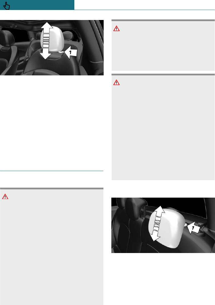
1. Fold the seat backrest forwards if neces-
sary.
2. Pull up the head restraint as far as it will
go.
3. Press the button, arrow 1, and pull the
head restraint fully out.
Installing
Proceed in the reverse order to install the
head restraint.
Rear head restraints
Safety notes
WARNING
If the head restraints are removed or in-
correctly adjusted, they cannot provide
protection as intended and head and neck
injuries may result. There is a danger of
injury.
–Before a journey, re-install any re-
moved head restraints on all occupied
seats.
–Adjust the head restraint so its centre
supports the back of the head at as
close to eye level as possible.
–Adjust the distance so that the head
restraint is as close as possible to the
back of the head. Set the distance via
the backrest tilt as needed.
WARNING
Parts of the body can become trapped
when the head restraints are moving.
There is a danger of injury. When moving
the head restraint, make sure that the area
of movement is kept clear.
WARNING
Objects on the head restraint reduce the
protective effect in the head and neck
area. There is a danger of injury.
–Do not fit any covers on the seats or
head restraints.
–Do not hang objects such as coat
hangers directly on the head re-
straint.
–Only use accessories that have been
classified as safe for attaching to the
head restraint.
–Do not use any accessories, for exam-
ple cushions, during the journey.
To adjust the height
–Downwards: press the button, arrow 1,
and slide the head restraint downwards.
–Upwards: push head restraint upwards.
After setting the height, move the head re-
straint up or down slightly, making sure it
engages properly.
Seite 86
CONTROLS Seats, mirrors and steering wheel
86 Online Edition for Part no. 01402988211 - II/18
Draft
from BA-76
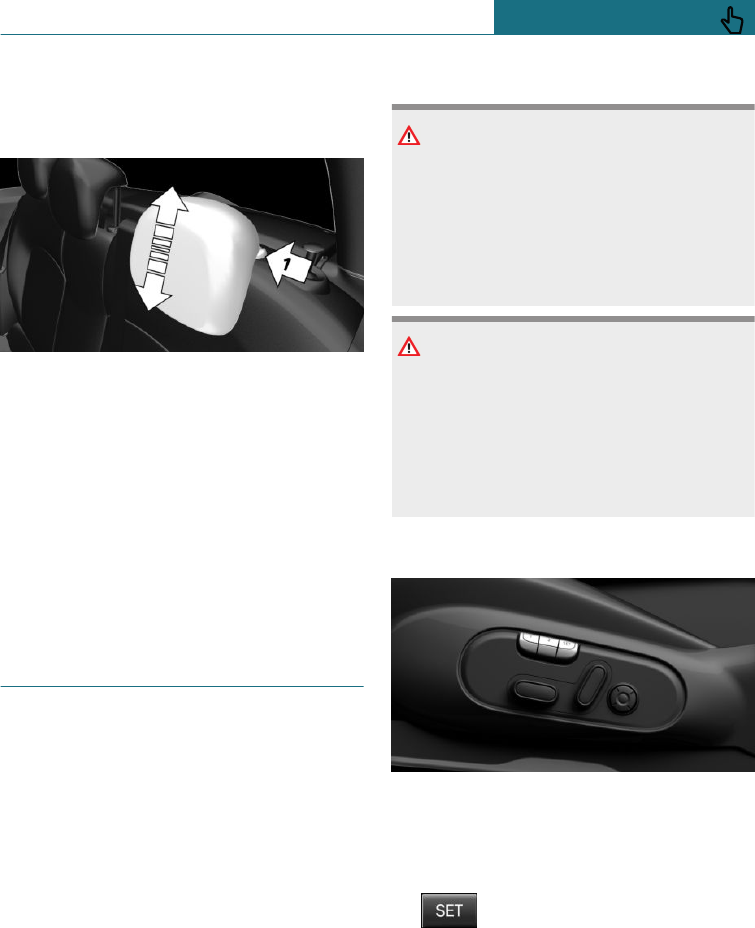
Removing
Only remove the head restraint if no-one is
intending to sit on the seat in question.
1. Fold down the corresponding rear back-
rest, see page 213.
2. Pull up the head restraint until resist-
ance is felt.
3. Press the button, arrow 1, and pull the
head restraint fully out.
Installing
Proceed in the reverse order to install the
head restraint.
Memory function
Principle
The memory function enables the following
settings to be stored and retrieved when re-
quired:
–Seat position.
–Exterior mirror position.
General
Two memory slots can be assigned with dif-
ferent settings.
The lumbar support setting is not saved.
Safety notes
WARNING
There is a risk of entrapment when the
seats are being moved. There is a danger
of injury or damage to property. Before
making any adjustment, make sure that
the area of movement of the seat is kept
clear.
WARNING
Using the memory function while driving
may cause the seat to move unexpectedly.
You could lose control of the vehicle.
There is a danger of accidents. Only call up
the memory function when the vehicle is
at standstill.
Overview
Saving
1. Switch on the ignition.
2. Set the desired position.
3. Press the button. The LED in
button is illuminated.
4. Press the desired button 1 or 2 while the
LED is illuminated. The LED is extin-
guished.
Seite 87
Seats, mirrors and steering wheel CONTROLS
87
Online Edition for Part no. 01402988211 - II/18
Draft
from BA-76
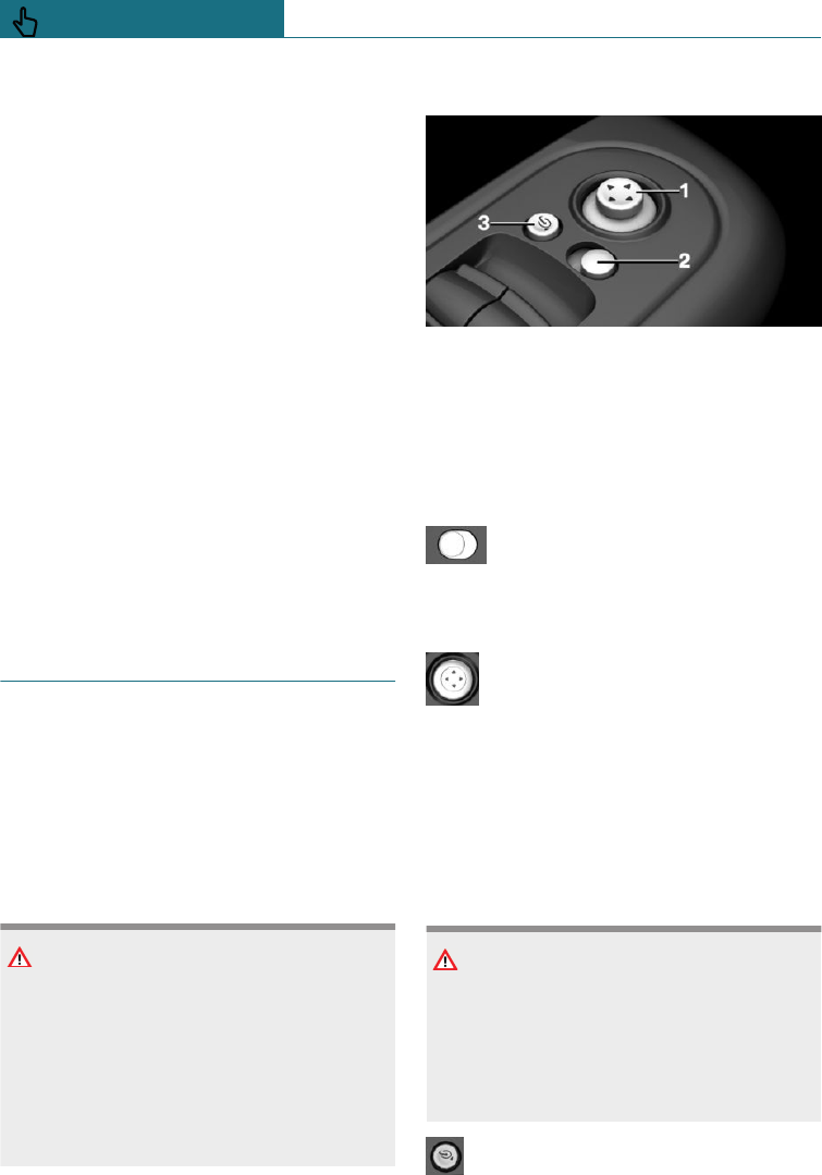
Recalling
The saved position is called up automati-
cally.
Press the desired button 1 or 2.
The operation is halted when you press a
seat adjustment switch or one of the mem-
ory buttons.
Adjusting the seat position on the driver's
side is interrupted after a short time during
the journey.
Recalling disabled
Recall of the saved seat positions is disa-
bled after a short while to prevent the bat-
tery from being discharged.
To reactivate recall:
–Open or close a door or the tailgate.
–Press a button on the remote control.
–Press the start/stop button.
Mirrors
Exterior mirrors
General
The current exterior mirror position can be
saved with the memory function, see
page 87.
Safety note
WARNING
Objects reflected in the mirror are closer
than they appear. The distance to road
users behind the vehicle could be incor-
rectly estimated, for example when chang-
ing lane. There is a danger of accidents.
Look over your shoulder to estimate the
distance from following traffic.
Overview
1To adjust
2To select a mirror, automatic parking
function
3To fold in and out
To select a mirror
To switch to the other mirror:
Push the switch.
Electrical adjustment
Press the button.
The mirror moves according to the
button movement.
Malfunction
In the event of an electrical fault, press the
edges of the mirror glass to adjust the mir-
ror.
To fold in and out
NOTE
Because of its width, the vehicle could
sustain damage in car washes. There is a
danger of damage to property. Before
washing, fold the mirrors in manually or
with the button.
Press the button.
Seite 88
CONTROLS Seats, mirrors and steering wheel
88 Online Edition for Part no. 01402988211 - II/18
Draft
from BA-76
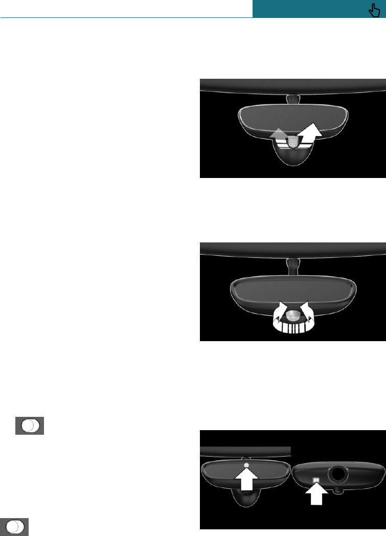
Folding in is possible up to a speed of ap-
prox. 20 km/h, 15 mph.
To fold the mirrors in and out is useful in
the following situations:
–In car washes.
–In narrow streets.
Folded-in mirrors automatically fold out
when the vehicle reaches a speed of approx-
imately 40 km/h, approximately 25 mph.
Automatic heating
Both exterior mirrors are automatically
heated when ignition is switched on.
Automatically dimming
The exterior mirror on the driver's side is
automatically dimmed. Photocells in the
rearview mirror, see page 89, are used to
control this function.
Automatic parking function,
exterior mirror
Principle
When reverse gear is engaged, the mirror
glass on the front passenger side is tilted
downwards. This improves the view of the
kerb or other obstacles near the ground, for
example when parking.
Activating
1. Push the switch to the driver's
mirror position.
2. Engaging selector lever position R.
When towing a trailer, the automatic park-
ing function is switched off.
Deactivating
Push the switch to the front pas-
senger's mirror position.
Rear-view mirror, manual-dim
Tilting lever
To reduce glare tilt the lever on the rear-
view mirror forward.
Turn button
Reduce glare from the rearview mirror by
turning the button.
Rear-view mirror, automatic-dim
Overview
The function is controlled by photocells:
Seite 89
Seats, mirrors and steering wheel CONTROLS
89
Online Edition for Part no. 01402988211 - II/18
Draft
from BA-76
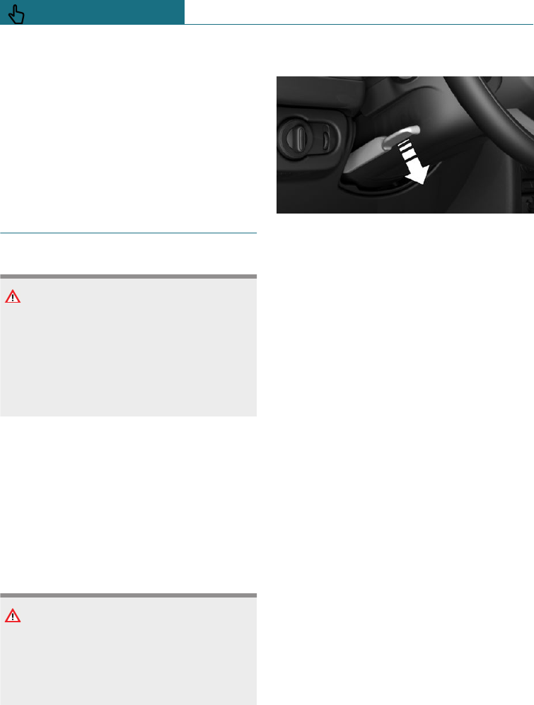
–In the mirror glass.
–On the back of the mirror.
Operating requirements
–Keep the photocells clean.
–Do not obstruct the zone between the
rearview mirror and the windscreen.
Steering wheel
Safety note
WARNING
To adjust the steering wheel while driving
may cause the steering wheel to move un-
expectedly. You could lose control of the
vehicle. There is a danger of accidents.
Only adjust the steering wheel when the
vehicle is at a standstill.
Electric steering wheel lock
General
Depending on the equipment, the steering
wheel locks automatically when the driver's
door is opened.
Switch on the ignition to unlock.
Safety note
WARNING
If steering wheel lock is activated, the ve-
hicle cannot be steered. There is a danger
of accidents. Switch on the ignition prior
to moving the vehicle.
To adjust
1. Switch on the ignition.
2. Fold the lever downwards.
3. Move the steering wheel to the prefer-
red height and angle to suit your seated
position.
4. Swing the lever back up.
5. Switch off the ignition again if neces-
sary.
Seite 90
CONTROLS Seats, mirrors and steering wheel
90 Online Edition for Part no. 01402988211 - II/18
Draft
from BA-76
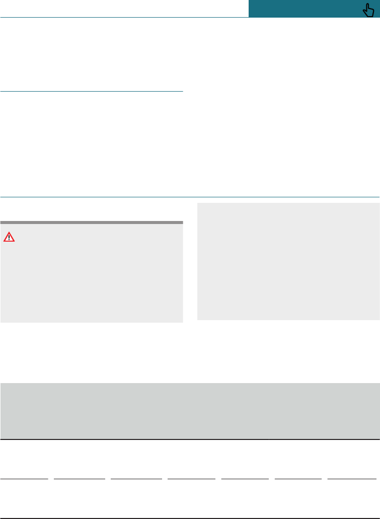
Carrying children safely
Vehicle equipment
This chapter describes all standard, country-
specific and special equipment available for
the model series. Therefore equipment
which is not installed in your vehicle, for
example on account of the optional equip-
ment selected or the country specification,
may also be described here. This also ap-
plies to safety-relevant functions and sys-
tems. Comply with the relevant laws and
regulations when using the corresponding
functions and systems.
Important considerations
Safety note
WARNING
Unsupervised children or animals in the
vehicle can set the vehicle in motion and
endanger themselves or other road users,
for example by the following actions:
–Pressing the start/stop button.
–Release the parking brake.
–Opening and closing doors or win-
dows.
–Engaging selector lever position N.
–Operating vehicle equipment.
There is a risk of accidents or injury. Do
not leave children or animals unsupervised
in the vehicle. When leaving the vehicle,
take the remote control with you and lock
the vehicle.
Not for Australia/New Zealand: Suitable seats
Information about which child restraint sys-
tems can be used on the seats in question if
the child restraint systems are attached
with a seat belt in accordance with the ECE-
R 16 standard:
Group Weight of
child Approxi-
mate age Front
passen-
ger seat,
airbag
ON
Front
passen-
ger seat,
airbag
OFF – a)
Rear
seats,
outer – b)
Rear seat,
middle –
c)
0 Up to
10 kg Up
to 9 month
s
X U, L U, L U
0+ Up to
13 kg Up
to 18 mont
hs
X U, L U, L U
Seite 91
Carrying children safely CONTROLS
91
Online Edition for Part no. 01402988211 - II/18
Draft
from BA-76
Group Weight of
child Approxi-
mate age Front
passen-
ger seat,
airbag
ON
Front
passen-
ger seat,
airbag
OFF – a)
Rear
seats,
outer – b)
Rear seat,
middle –
c)
I 9 – 18 kg Up
to 4 years X U, L U, L– d) U
II 15 – 25 kg Up
to 7 years X U, L U, L– d) U
III 22 – 36 kg 7 years or
more X U, L U, L– d) U
U: suitable for child restraint systems in the Universal category that have been approved
for use in this weight group.
L: suitable for child restraint systems in the Semi-Universal category if the vehicle and
the seat are listed in the list of vehicle models from the manufacturer of the child re-
straint system.
X: not suitable for child restraint systems in the Universal category that have been ap-
proved for use in this weight group.
a) Adapt the front/back position of the front passenger seat and, if necessary, move it to
the highest position to achieve the best possible routing of the belt.
b) When using child seats on the outer rear seats, adapt the front/back position of the
front seat, and also adjust the head restraint of the rear seat, or remove it.
c) If a child restraint system is mounted on the middle rear sear: the outer rear seats are
only allowed to be occupied if the outer belt buckles can be freely accessed. The seat is
not suitable for child restraint systems with a support stand.
d) Adjust the inclination of the rear backrest to achieve the best possible routing of the
belt.
Children always in the rear seats
General
Accident research has shown that the safest
place for children is on the rear seat.
Children younger than 12 years old or less
than 150 cm, 5 ft in height are only allowed
to be transported in the rear using child re-
straint systems appropriate for their age,
weight and stature. Children older than
12 years must be secured with a seat belt as
soon as a suitable child restraint system is
no longer appropriate due to their age,
weight and stature.
Safety note
WARNING
Children less than 150 cm, 5 ft in height
cannot wear the seat belt correctly with-
out using additional child restraint sys-
tems. The protective function of the seat
belts may be limited or may even fail com-
pletely if the seat belts are worn incor-
rectly. If a seat belt is not worn correctly,
Seite 92
CONTROLS Carrying children safely
92 Online Edition for Part no. 01402988211 - II/18
Draft
from BA-76

additional injuries can be caused, for ex-
ample in the event of an accident or brak-
ing and evasive manoeuvres. There is a
danger of injury or even death. Children
smaller than 150 cm, 5 ft in height must
be secured in suitable child restraint sys-
tems.
Not for Australia/New Zealand:
Children on the front passenger
seat
General
When using a child restraint system on the
front passenger seat, make sure that the
front and side airbags on the passenger side
are deactivated. Front passenger airbags
can only be deactivated with the key switch
for front passenger airbags, see page 150.
Safety notes
WARNING
Active front passenger airbags can injure
a child in a child restraint system if they
are triggered. There is a danger of injury.
Make sure that the front passenger air-
bags are deactivated and the PASSENGER
AIRBAG OFF indicator lamp is illumina-
ted.
WARNING
If the seat adjustment or child seat instal-
lation is incorrect, the child restraint sys-
tem may have limited stability or may not
be stable at all. There is a danger of injury
or even death. Make sure the child re-
straint system is firmly positioned against
the backrest. Wherever possible, adapt the
backrest angle of all the relevant seat
backrests and adjust the seats correctly.
Make sure that the seats and their backr-
ests are correctly engaged or locked. If
possible, adjust the height of the head re-
straints, or remove them.
Fitting child restraints
General
Appropriate child restraint systems for ev-
ery age and weight class are available from
a Service Partner of the manufacturer or an-
other qualified Service Partner or a special-
ist workshop.
When selecting, installing and using child
restraint systems, comply with the informa-
tion provided by the manufacturer of the
child restraint system.
Safety notes
WARNING
If child restraint systems and their attach-
ment systems have been damaged or sub-
jected to stresses in an accident, their pro-
tective function may be limited or may fail
completely. A child might not be ade-
quately restrained, for example, in the
event of an accident or braking and eva-
sive manoeuvres. There is a danger of in-
jury or even death. If child restraint sys-
tems and their attachment systems have
been damaged or subjected to stresses in
an accident, have them checked by a Serv-
ice Partner of the manufacturer or another
qualified Service Partner or a specialist
workshop and renewed if necessary.
Seite 93
Carrying children safely CONTROLS
93
Online Edition for Part no. 01402988211 - II/18
Draft
from BA-76
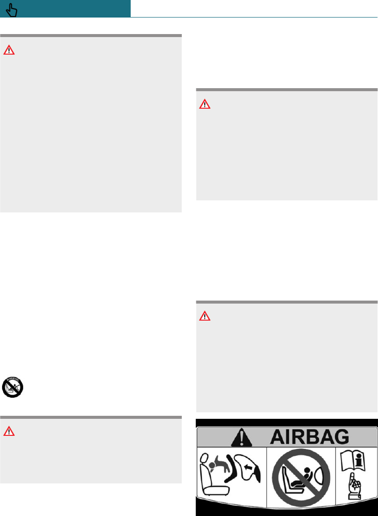
WARNING
If the seat adjustment or child seat instal-
lation is incorrect, the child restraint sys-
tem may have limited stability or may not
be stable at all. There is a danger of injury
or even death. Make sure the child re-
straint system is firmly positioned against
the backrest. Wherever possible, adapt the
backrest angle of all the relevant seat
backrests and adjust the seats correctly.
Make sure that the seats and their backr-
ests are correctly engaged or locked. If
possible, adjust the height of the head re-
straints, or remove them.
On the back seats
If the vehicle equipment includes a movea-
ble rear seat: before installation of a child
restraint system, move the seats into the
rearmost position.
For Australia/New Zealand:
installation of child restraints
Please note the following warning because
your vehicle has been equipped with a front
airbag for the front passenger seat that can-
not be deactivated:
It is recommended not to use any
kind of child restraint system on the
front passenger seat.
Extreme hazard
Do not use a rearward-facing child re-
straint on a seat protected by an airbag in
front of it.
Not for Australia/New Zealand: On
the front passenger seat
Deactivating airbags
WARNING
Active front passenger airbags can injure
a child in a child restraint system if they
are triggered. There is a danger of injury.
Make sure that the front passenger air-
bags are deactivated and the PASSENGER
AIRBAG OFF indicator lamp is illumina-
ted.
Before fitting a child restraint on the front
passenger seat, make sure that the front and
side airbags on the passenger side are disa-
bled.
Deactivating the front passenger airbags
with key switch, see page 150.
Rearward-facing child restraints
DANGER
Active front passenger airbags can fatally
injure a child in a rearward-facing child re-
straint system if they are triggered. There
is a danger of injury or even death. Make
sure that the front passenger airbags are
deactivated and the PASSENGER AIRBAG
OFF indicator lamp is illuminated.
Follow the information on the front passen-
ger sun visor.
Seite 94
CONTROLS Carrying children safely
94 Online Edition for Part no. 01402988211 - II/18
Draft
from BA-76

NEVER use a rearward facing child re-
straint on a seat protected by an ACTIVE
AIRBAG in front of it, DEATH or SERIOUS
INJURY to the CHILD can occur.
Seat position and height
Before mounting a universal child restraint
system, move the front passenger seat as far
to the rear and as far up as possible to ach-
ieve the best possible routing of the belt
and protection in the event of an accident.
If the upper attachment point of the seat
belt is located ahead of the child seat's belt
guide, carefully move the front passenger
seat forwards until the best possible belt
guidance is achieve.
ISOFIX child seat mountings
General
Note for Australia: ISOFIX child seats are
not permitted for road use in Australia at
the time of printing of this handbook. How-
ever, also since a change of the respective
regulations is expected in the future, lower
ISOFIX anchorages are supplied in line with
applicable ADRs also for Australia.
Comply with the operating and safety notes
from the manufacturer of the child restraint
system when attaching and using ISOFIX
child restraint systems.
Suitable ISOFIX child restraint systems
The following ISOFIX child restraints may
be used on the seats designated as appropri-
ate for this purpose. The corresponding size
class and size category are denoted by a let-
ter or ISO reference on a plate on the child
seat.
Group Weigh
t of
child
Ap-
proxi-
mate
age
Class/cate-
gory – a) Front
passen-
ger
seat,
airbag
ON
Front
passen-
ger seat,
airbag
OFF – b)
Rear
seats,
outer
2nd seat
row
Rear
seat,
middle
2nd
seat
row
Carrycot F - ISO/L1
G - ISO/L2
X
X
X
X
IL
IL
X
X
0 Up to
10 kg Up
to 9 mo
nths
E - ISO/R1 X IL IL X
0+ Up to
13 kg Up
to 18 m
onths
E - ISO/R1
D - ISO/R2
C - ISO/R3
X
X
X
IL
IL
IL
IL
IL
IL
X
X
X
Seite 95
Carrying children safely CONTROLS
95
Online Edition for Part no. 01402988211 - II/18
Draft
from BA-76
Group Weigh
t of
child
Ap-
proxi-
mate
age
Class/cate-
gory – a) Front
passen-
ger
seat,
airbag
ON
Front
passen-
ger seat,
airbag
OFF – b)
Rear
seats,
outer
2nd seat
row
Rear
seat,
middle
2nd
seat
row
I 9 -
18 kg Up
to 4 ye
ars
D - ISO/R2
C - ISO/R3
B - ISO/F2
B1 -
ISO/F2X
A - ISO/F3
X
X
X
X
X
IL
IL
IL, IUF
IL, IUF
IL, IUF
IL – c)
IL – c)
IL, IUF –
c)
IL, IUF –
c)
IL, IUF –
c)
X
X
X
X
X
a) When using child seats on the rear seats, adapt the front/back position of the front seat
if necessary, and also adjust the head restraint of the rear seat, or remove it.
b) Only if equipped with ISOFIX child seat mountings.
c) Adjust the inclination of the rear seat backrest to achieve the best possible routing of
the belt.
IL: suitable for ISOFIX child restraint systems in Semi-Universal category if the vehicle
and the seat are listed in the vehicle type list of the manufacturer of the child restraint
system.
IUF: suitable for forward-facing ISOFIX child restraint systems in the Universal category
that have been approved for use in this weight class.
X: the seat is not approved or equipped with mounting points for the ISOFIX system.
Brackets for lower ISOFIX anchors
Safety note
WARNING
If the ISOFIX child restraint systems are
not engaged correctly, the protective ef-
fect of the ISOFIX child restraint systems
may be limited. There is a danger of injury
or even death. Make sure the lower anchor
point has engaged correctly and the ISO-
FIX child restraint system is firmly posi-
tioned against the backrest.
Rear seat: position
Symbol Meaning
The corresponding symbol
shows the brackets for
lower ISOFIX anchor
points.
Seite 96
CONTROLS Carrying children safely
96 Online Edition for Part no. 01402988211 - II/18
Draft
from BA-76
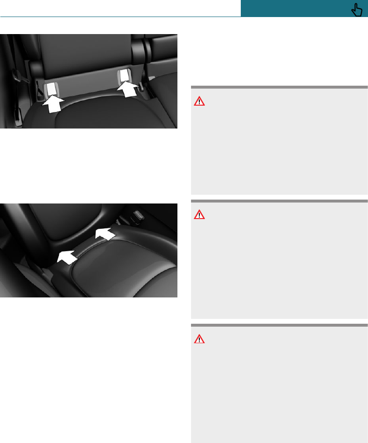
The brackets for the lower ISOFIX anchors
are located behind the marked covers.
Not for Australia/New
Zealand:Front passenger seat
The brackets for the lower ISOFIX anchors
are located in the gap between the seat and
backrest.
Before fitting ISOFIX child
restraints
Pull the seat belt away from the area of the
child seat mountings.
Fitting ISOFIX child restraints
1. Install the child restraint system, see the
manufacturer's instructions.
2. Make sure that both ISOFIX anchors are
locked correctly in place.
Mounts for the upper ISOFIX
retaining strap
Safety notes
WARNING
If the upper retaining strap is used incor-
rectly with the child restraint system, the
protective effect may be reduced. There is
a danger of injury. Make sure that the up-
per retaining strap is not routed to the up-
per attachment strap over sharp edges,
and that it is not twisted.
WARNING
If the rear backrest is not locked, the pro-
tective effect of the child restraint system
is limited or non-existing. The rear back-
rest can fold forward in certain situations,
for example braking manoeuvre or acci-
dent. There is a danger of injury or even
death. Make sure that the rear backrests
are locked.
NOTE
The mounting points for the upper retain-
ing straps of child restraint systems are
only intended for these retaining straps.
The mounting points can be damaged if
other objects are attached. There is a dan-
ger of damage to property. Only attach
child restraint systems to the upper retain-
ing straps.
Seite 97
Carrying children safely CONTROLS
97
Online Edition for Part no. 01402988211 - II/18
Draft
from BA-76
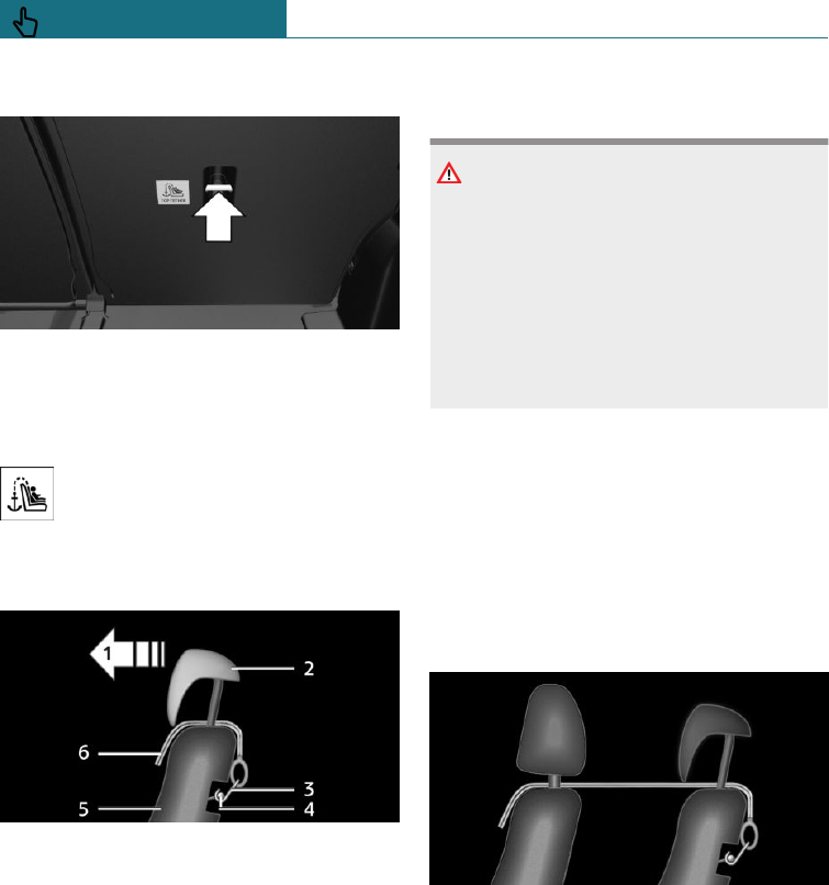
Mounting points
There are two mounting points on the back
of the rear seat backrest for the upper re-
taining strap of ISOFIX child restraint sys-
tems.
The mounting point for the upper re-
taining strap is identified with a Top
Tether symbol.
Routing the retaining strap
1Direction of travel
2Head restraint
3Hook for the upper retaining strap
4Mounting point
5Seat backrest
6Upper retaining strap
Attaching the upper retaining strap to
the mounting point
WARNING
In the event of an accident, persons sitting
in the rear can come in contact with the
tensioned retaining strap of the child re-
straint system on the front passenger seat.
There is a danger of injury or even death.
Do not transport persons on the rear seat
behind the front passenger seat if a child
restraint system is mounted.
1. Raise the head restraint if necessary.
2. On the rear seat: Guide the upper retain-
ing strap between or along both sides of
the head restraint mounts to the mount-
ing point.
3. Engage the hook of the retaining strap
in the mounting point on the rear seat.
4. Tighten the retaining strap by pulling it
firmly down.
On the front passenger seat: guide the up-
per retaining strap between the head re-
straint mounts on the front passenger seat
and the rear seat on the passenger side.
i-Size child restraint systems
General
i-Size is a regulation for child restraint sys-
tems, which is used for the approval of child
restraint systems.
Seite 98
CONTROLS Carrying children safely
98 Online Edition for Part no. 01402988211 - II/18
Draft
from BA-76
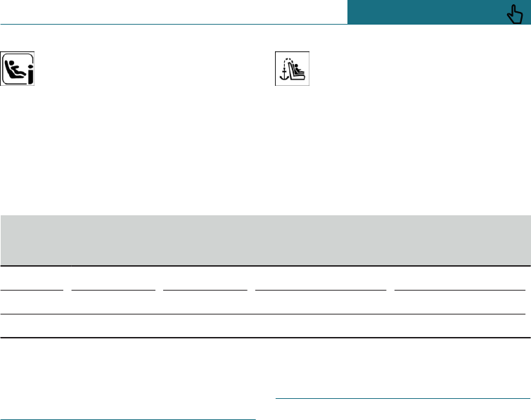
If this symbol is seen in the vehicle,
the vehicle has been approved in ac-
cordance with i-Size. The symbol
shows the mounts for the system's lower an-
chors.
The symbol shows the mounting
point for the upper retaining strap.
Suitable i-Size seats
Information on the suitability of the differ-
ent vehicle seats for the installation of child
restraint systems suitable for i-Size or
meeting i-Size requirements - in accordance
with standard ECE-R 129:
Group Front pas-
senger seat,
airbag ON
Front pas-
senger seat,
airbag OFF
Rear seats, outer
2nd seat row
Rear seat, middle
2nd seat row
i-Size X X i-U X
i-U, suitable for rearward and forward-facing i-Size child restraint systems.
X: not suitable for i-Size child restraint systems.
Not for Australia/New Zea-
land: Recommended child
seats
Appropriate child restraint systems for ev-
ery age and weight class are available from
a Service Partner of the manufacturer or an-
other qualified Service Partner or a special-
ist workshop.
The manufacturer of the vehicle recom-
mends the following child restraint systems:
–MINI Baby Seat Group 0+.
–MINI Junior Seat Group 1.
–MINI Junior Seat Group 2/3.
–ISOFIX base.
–Römer KidFix XP.
For Australia/New Zealand:
Child restraints
General
In accordance with ADR 34/02, provisions
have been made to allow installation of a
child restraint at each rear seating position.
The anchoring hooks which belong to the
upper retraining strap of the child restraint
- AS 1754, can be applied immediately to
the relevant mounting.
Please refer strictly to the installation in-
structions supplied with the child restraint
system.
Each seating position is fitted with a head
rest.
Seite 99
Carrying children safely CONTROLS
99
Online Edition for Part no. 01402988211 - II/18
Draft
from BA-76
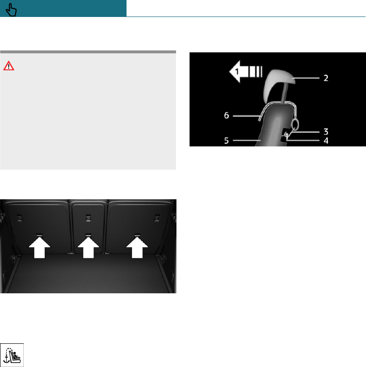
Safety notes
WARNING
Child restraint anchorages are designed to
withstand only those loads imposed by
correctly fitted child restraints. Under no
circumstances are they to be used for
adult seat belts, harnesses or for attaching
other items or equipment to the vehicle.
After using the child restraints, fold the
anchor fittings down again if necessary.
Mounting points
There are three mounting points for the up-
per retaining strap of ISOFIX child re-
straints.
The mounting point for the upper re-
taining strap is identified with a Top
Tether symbol.
Routing the retaining strap
1Direction of travel
2Head restraint
3Hook for the upper retaining strap
4Mounting point
5Seat backrest
6Upper retaining strap
Attaching the upper retaining strap
to the mounting point
1. Raise the head restraint if necessary.
2. Guide the upper retaining strap between
or along both sides of the head restraint
mounts to the mounting point.
3. Engage the hook of the retaining strap
in the mounting point on the rear seat.
4. Tighten the retaining strap by pulling it
firmly down.
Seite 100
CONTROLS Carrying children safely
100 Online Edition for Part no. 01402988211 - II/18
Draft
from BA-76
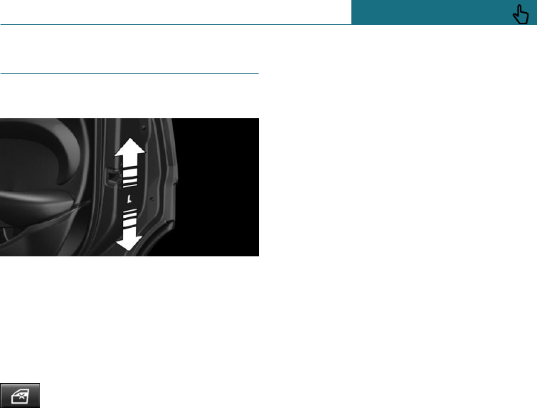
Locking doors and windows
Doors
Push up the locking levers on the rear
doors.
The door in question can now only be
opened from the outside.
Safety switch for the rear
Press the button on the driver's
door if children are travelling in the
rear.
Various functions are blocked and cannot
be operated in the rear, safety switch, see
page 73.
Seite 101
Carrying children safely CONTROLS
101
Online Edition for Part no. 01402988211 - II/18
Draft
from BA-76
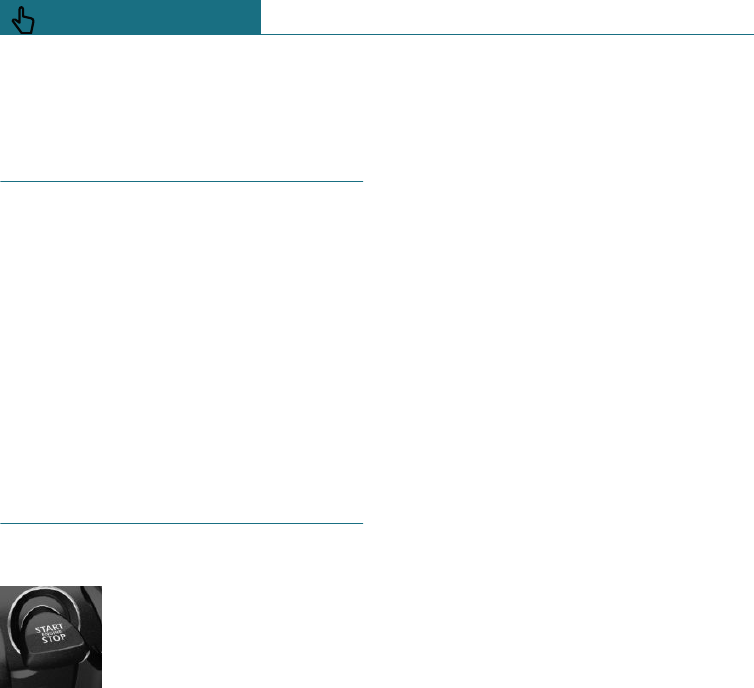
Driving
Vehicle equipment
This chapter describes all standard, country-
specific and special equipment available for
the model series. Therefore equipment
which is not installed in your vehicle, for
example on account of the optional equip-
ment selected or the country specification,
may also be described here. This also ap-
plies to safety-relevant functions and sys-
tems. Comply with the relevant laws and
regulations when using the corresponding
functions and systems.
Start/stop button
Principle
The ignition is switched on or
off and the engine is started
by pressing the start/stop but-
ton.
Steptronic transmission: the
engine starts in selector lever position P or
N if the brakes are applied when the start/
stop button is pressed.
Manual gearbox: the engine starts if the
clutch pedal is pressed when pressing the
start/stop button.
Ignition on
Manual gearbox: press the start/stop but-
ton, do not press the clutch pedal.
Steptronic transmission: press the start/
stop button, do not apply the brake.
All systems are operational.
Most of the indicator and warning lamps in
the instrument cluster are illuminated for
different lengths of time.
To save battery power when the engine is
off, switch off the ignition and any unneces-
sary power consumers.
Ignition off
Manual gearbox: press the start/stop button
again, do not press the clutch pedal.
Steptronic transmission: press the start/
stop button again, do not apply the brake.
All indicator lamps in the instrument cluster
extinguish.
To save battery power when the engine is
off, switch off the ignition and any unneces-
sary power consumers.
Safety measures
With the vehicle stationary and the engine
shut down, the ignition is switched off auto-
matically under the following circumstan-
ces:
–When locking, even with the low-beam
headlights switched on.
–Shortly before the battery is discharged
so that an engine start remains possible.
This function is only available with the
low-beam headlights switched off.
–When opening or closing the driver's
door, if the driver's seat belt is unfas-
tened and the low-beam headlights are
switched off.
–When the driver's seat belt is unfas-
tened, if the driver's door is opened and
the low-beam headlights switched off.
–When opening the front doors, if there
is no other person on the front seats.
–After some minutes without further op-
eration, the low-beam headlights are
changed over to side lights.
Seite 102
CONTROLS Driving
102 Online Edition for Part no. 01402988211 - II/18
Draft
from BA-76
Steptronic transmission with a tap-operated
selector lever, see page 116: when the igni-
tion is switched off, the selector lever will
shift automatically to position P if it was
previously in position R, D or M/S.
Radio ready state
General
In the radio ready state, individual current
consumers remain ready for operation.
Activating
When the engine is running, press the
start/stop button.
If engine is switched off and the ignition is
switched on: the system automatically acti-
vates radio ready state when the door is
opened if the lights are switched off or the
daytime driving lights are switched on.
Radio ready state remains active when igni-
tion is switched off automatically, such as
for the following reasons:
–When the driver's door is opened or
closed.
–When the driver's seat belt is unfas-
tened.
–When the low-beam headlights are auto-
matically switched to side lights.
Switching off automatically
The radio ready state is automatically
switched off in the following situations:
–If the driver's or front passenger door is
opened when exiting the vehicle, with
the engine stopped manually.
–If the ignition is switched off manually
with the start/stop button.
–After approximately 8 minutes.
–When locking via the central locking
system.
–Shortly before the battery is discharged
so that an engine start remains possible.
Engine start
Safety notes
DANGER
A blocked exhaust pipe or inadequate ven-
tilation can allow harmful exhaust fumes
to penetrate the vehicle. The exhaust
fumes contain pollutants which are colour-
less and odourless. In enclosed spaces, the
exhaust fumes can also build up outside
the vehicle. There is a danger of fatal in-
jury. Keep the exhaust pipe clear and en-
sure sufficient ventilation.
WARNING
An unsecured vehicle can start moving
and rolling away. There is a danger of acci-
dents. Before leaving the vehicle, secure it
to prevent it from rolling away.
Observe the following to ensure that the
vehicle is secured against rolling away:
–Apply the parking brake.
–Turn the front wheels towards the
kerb on upward or downward gradi-
ents.
–Additionally secure the vehicle on up-
ward or downward gradients, for ex-
ample with a chock.
NOTE
Repeated start attempts or starting several
times in quick succession means that fuel
is not burned or is inadequately burned.
The catalytic converter can overheat.
There is a danger of damage to property.
Seite 103
Driving CONTROLS
103
Online Edition for Part no. 01402988211 - II/18
Draft
from BA-76

Avoid repeated starting in quick succes-
sion.
Diesel engine
With the engine cold and at temperatures
below 0 ℃, 32 ℉ the starting operation can
be delayed slightly due to automatic pre-
heating.
A Check Control message is shown.
Steptronic transmission
Starting the engine
1. Depress the brake pedal.
2. Engaging the selector lever in position P
or N.
3. Press the start/stop button.
Starting proceeds for a short time automati-
cally and stops as soon as the engine has
started.
Manual gearbox
Starting the engine
1. Depress the brake pedal.
2. Press the clutch and engage idle posi-
tion.
3. Press the start/stop button.
Starting proceeds for a short time automati-
cally and stops as soon as the engine has
started.
Stopping the engine
Safety notes
WARNING
Unsupervised children or animals in the
vehicle can set the vehicle in motion and
endanger themselves or other road users,
for example by the following actions:
–Pressing the start/stop button.
–Release the parking brake.
–Opening and closing doors or win-
dows.
–Engaging selector lever position N.
–Operating vehicle equipment.
There is a risk of accidents or injury. Do
not leave children or animals unsupervised
in the vehicle. When leaving the vehicle,
take the remote control with you and lock
the vehicle.
WARNING
An unsecured vehicle can start moving
and rolling away. There is a danger of acci-
dents. Before leaving the vehicle, secure it
to prevent it from rolling away.
Observe the following to ensure that the
vehicle is secured against rolling away:
–Apply the parking brake.
–Turn the front wheels towards the
kerb on upward or downward gradi-
ents.
–Additionally secure the vehicle on up-
ward or downward gradients, for ex-
ample with a chock.
Seite 104
CONTROLS Driving
104 Online Edition for Part no. 01402988211 - II/18
Draft
from BA-76

Steptronic transmission
Stopping the engine
1. Apply the parking brake when the vehi-
cle is stationary.
2. Engaging the selector lever in posi-
tion P.
3. Press the start/stop button.
The engine is switched off.
The radio ready state is switched on.
Manual gearbox
Stopping the engine
1. Press the Start/Stop button when the
vehicle is at standstill.
The engine is switched off.
The radio ready state is switched on.
2. Engage first gear or reverse.
3. Apply the parking brake.
Auto Start Stop function
Principle
The Auto Start Stop function helps you to
save fuel. The system stops the engine
when stationary, for example in a traffic jam
or at traffic lights. The ignition remains
switched on. For driving off, the engine
starts automatically.
Each time the engine is started via the
start/stop button, the Auto Start/Stop func-
tion is switched to standby and is activated
from approximately 5 km/h, approximately
3 mph.
Depending on selected drive mode, see
page 172, the system is activated or deacti-
vated automatically.
Stopping the engine
Operating requirements
The engine is automatically shut down
when stationary under the following condi-
tions:
Manual gearbox:
–Gearbox in neutral and clutch pedal not
pressed.
–Driver's seat belt buckled or driver's
door closed.
Steptronic transmission:
–Selector lever in selector lever position
D.
–Brake pedal remains pressed while the
vehicle is at a standstill.
–Driver's seat belt buckled or driver's
door closed.
To be able to release the brake pedal when
the vehicle is stationary, engage the selec-
tor lever in the P position. The engine re-
mains switched off.
Press the brake pedal to continue driving.
The engine starts automatically when a gear
is engaged.
The air flow rate of the air conditioning sys-
tem is reduced when the engine is not run-
ning.
Steptronic transmission: manual
engine stop
Depending on the equipment and country
version, the engine can be switched off
manually, if the engine was not switched off
automatically when the vehicle came to a
stop:
–Rapidly press the brake pedal from the
current position.
–Engaging the selector lever in posi-
tion P.
If all the operating requirements have been
met, the engine is shut down.
Seite 105
Driving CONTROLS
105
Online Edition for Part no. 01402988211 - II/18
Draft
from BA-76
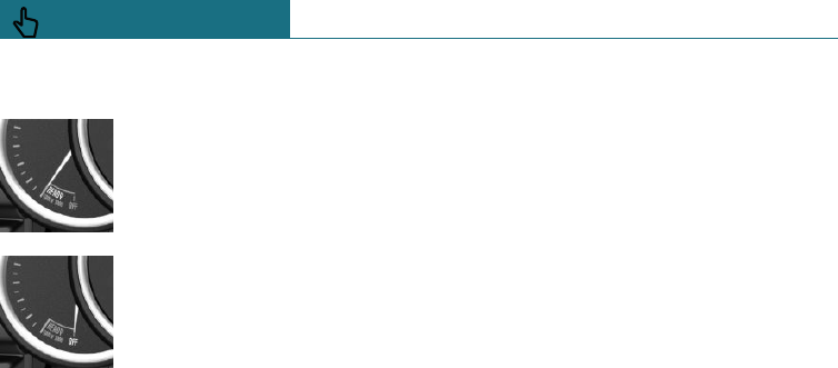
Displays in the instrument cluster
The display indicates that the
Auto Start Stop function is
ready for automatically start-
ing the engine.
The display indicates that the
preconditions for an automatic
engine stop are not met.
Functional limitations
The engine is not shut down automatically
in the following situations:
–Outside temperature too low.
–High outside temperature and operation
of the automatic air conditioning.
–Interior not heated or cooled to the de-
sired temperature.
–Engine is not yet at operating tempera-
ture.
–Sharp steering angle or steering opera-
tion.
–After reversing.
–Condensation forms on the windows
when the automatic air conditioning is
switched on.
–Vehicle battery in a low state of charge.
–At high altitudes.
–Bonnet is unlocked.
–Park Assistant is activated.
–Stop-and-go traffic.
–Selector lever in selector lever position
R, N or M/S.
Engine start
For driving off, the engine automatically
starts under the following conditions:
–Manual gearbox: by depressing the
clutch pedal.
–Steptronic transmission: by releasing
the brake pedal.
After starting the engine, accelerate as nor-
mal.
Safety function
After an automatic shut down, the engine
will not restart automatically, if one of the
following conditions is met:
–Driver's seat belt unbuckled and driver's
door open.
–Bonnet has been unlocked.
Several indicator lamps illuminate for vari-
ous lengths of time.
The engine can only be started using the
start/stop button.
Functional limitations
Even if you do not want to drive off, the en-
gine restarts automatically in the following
situations:
–Very high temperature in the interior
when the cooling function is switched
on.
–The driver applies lock to the steering
wheel.
–Steptronic transmission: shift from se-
lector lever position D to R, N or M/S.
–Steptronic transmission: shift from se-
lector lever position P to R, N, D or M/S.
–Vehicle starts to roll.
–Condensation forms on the windows
when the automatic air conditioning is
switched on.
–Vehicle battery in a low state of charge.
–Very low temperature in the interior
when the heating is switched on.
Seite 106
CONTROLS Driving
106 Online Edition for Part no. 01402988211 - II/18
Draft
from BA-76
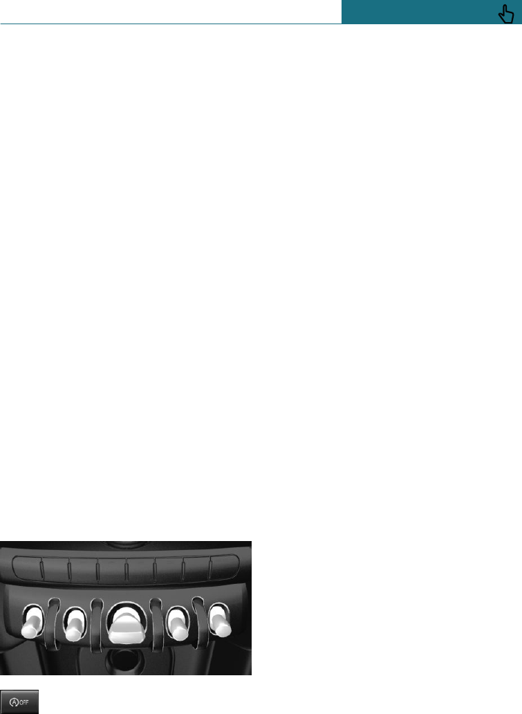
–Manual gearbox: low brake vacuum, for
example because the brake pedal has
been pressed a number of times in suc-
cession.
Intelligent Auto Start Stop function
Depending on the equipment version and
country version, the vehicle has various
sensors to record the traffic situation. This
enables the intelligent Auto Start Stop func-
tion to adapt to various traffic situations
and, where necessary, behave in an antici-
patory manner.
For example, in the following situations:
–If a situation is detected in which the
duration of the stop is likely to be very
short, the engine is not stopped auto-
matically. Depending on the situation, a
message is shown on the Control Dis-
play.
–If a situation is detected in which the
vehicle should drive off immediately, the
stopped engine is started automatically.
The function may be limited if the naviga-
tion data is invalid, outdated or not avail-
able, for example.
Switches system on/off
Using the button
Press the button.
–LED illuminates: Auto Start Stop func-
tion is deactivated.
During an automatic engine stop, the
engine is started.
The engine can be started or stopped
only by means of the start/stop button.
–The LED is extinguished: Auto Start
Stop function is activated.
Parking the vehicle during automatic
engine stop
With automatic engine stop, the vehicle can
be parked safely, for example in order to
leave it.
Steptronic transmission:
1. Engaging the selector lever in posi-
tion P.
2. Press the start/stop button. The ignition
is switched off. The Auto Start Stop
function is deactivated.
3. Apply the parking brake.
Manual gearbox:
1. Press the start/stop button. The ignition
is switched off. The Auto Start Stop
function is deactivated.
2. Engage first gear or reverse.
3. Apply the parking brake.
Start engine as usual, using the start/stop
button.
Automatic deactivation
In certain situations the Auto Start Stop
function is deactivated automatically for
safety reasons, for example if the absence of
the driver is detected.
Malfunction
The Auto Start Stop function no longer
shuts down the engine automatically. A
Check Control message is shown. It is possi-
ble to keep driving. Have the system
checked by a Service Partner of the manu-
Seite 107
Driving CONTROLS
107
Online Edition for Part no. 01402988211 - II/18
Draft
from BA-76
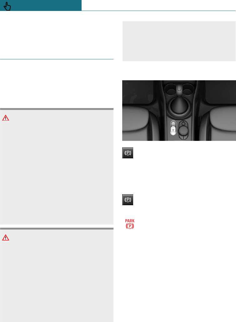
facturer or another qualified Service Partner
or a specialist workshop.
Parking brake
Principle
The parking brake is used to prevent the ve-
hicle from rolling when it is parked.
Safety notes
WARNING
An unsecured vehicle can start moving
and rolling away. There is a danger of acci-
dents. Before leaving the vehicle, secure it
to prevent it from rolling away.
Observe the following to ensure that the
vehicle is secured against rolling away:
–Apply the parking brake.
–Turn the front wheels towards the
kerb on upward or downward gradi-
ents.
–Additionally secure the vehicle on up-
ward or downward gradients, for ex-
ample with a chock.
WARNING
Unsupervised children or animals in the
vehicle can set the vehicle in motion and
endanger themselves or other road users,
for example by the following actions:
–Pressing the start/stop button.
–Release the parking brake.
–Opening and closing doors or win-
dows.
–Engaging selector lever position N.
–Operating vehicle equipment.
There is a risk of accidents or injury. Do
not leave children or animals unsupervised
in the vehicle. When leaving the vehicle,
take the remote control with you and lock
the vehicle.
Overview
Parking brake
Engaging
When the vehicle is stationary
Pull the switch.
The LED is illuminated.
The indicator lamp illuminates red.
The parking brake is engaged.
Depending on the parking situation, the
parking brake is automatically engaged.
Steptronic transmission: in some parking
situations, engaging selector lever posi-
tion P automatically applies the parking
brake. In these cases, the parking brake is
automatically disengaged when shifting
from selector lever position P.
While the vehicle is in motion
Use during the journey serves as an emer-
gency brake:
Pull and hold the switch. Vehicle brakes
strongly for as long as the switch is pulled.
Seite 108
CONTROLS Driving
108 Online Edition for Part no. 01402988211 - II/18
Draft
from BA-76
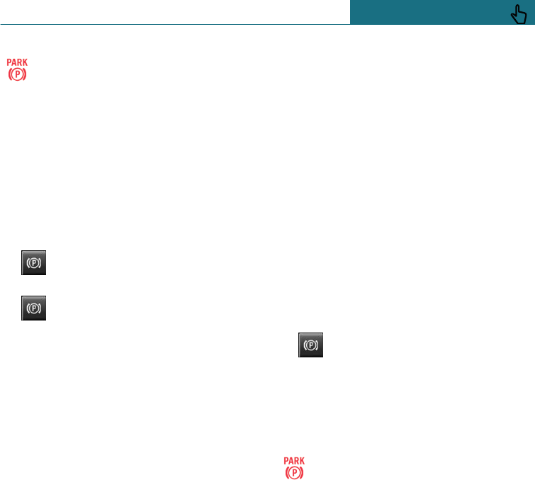
The indicator lamp illuminates red, a
signal sounds and the brake lights il-
luminate.
A Check Control message is shown.
If the vehicle is braked to a standstill, the
parking brake is applied.
Releasing
Releasing manually
1. Switch on the ignition.
2. Manual transmission: press the
button with the brake pedal depressed.
Steptronic transmission: press the
switch with the brake pedal depressed
or selector lever position P engaged.
LED and indicator lamp turn off.
The parking brake is released.
Automatic release with Steptronic
transmission
Operate the accelerator pedal to release au-
tomatically.
LED and indicator lamp turn off.
The parking brake is automatically released
by operating the accelerator pedal if the
following conditions are met:
–Engine on.
–Drive position engaged.
–Driver's seat belt fastened and door
closed.
Automatic release with manual
gearbox
Drive off as usual. The parking brake is re-
leased when the clutch pedal is released.
LED and indicator lamp turn off.
Under the following preconditions, the park-
ing brake is released automatically:
–Engine on.
–Gear engaged.
–Driver's seat belt fastened and door
closed.
–Engine power is sufficient to start off.
Malfunction
If the parking brake fails or malfunctions,
secure the vehicle against rolling away, for
example with a chock, if you leave the vehi-
cle.
After a power failure
Initial operation
1. Switch on the ignition.
2. Press the switch with the brake
pedal depressed or selector lever posi-
tion P engaged.
It can take a few seconds to put the brake
into operation. Any sounds that occur are
normal.
The indicator lamp in the instrument
cluster extinguishes when the park-
ing brake is operational again.
Seite 109
Driving CONTROLS
109
Online Edition for Part no. 01402988211 - II/18
Draft
from BA-76
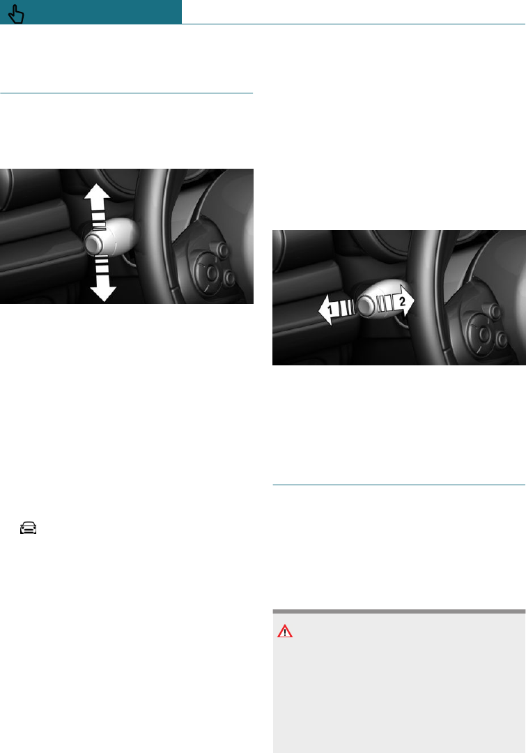
Turn indicators, high-beam
headlights, headlight flasher
Turn indicator
Indicating
Press the lever beyond the resistance point.
The lever returns to its initial position after
activation.
To cancel the signal manually, press the
lever gently as far as the resistance point.
Triple turn signal
Briefly press the lever up or down.
The duration of the triple turn signal can be
set.
Using the on-board monitor:
1. "My MINI"
2. "Vehicle settings"
3. "Lights"
4. "Exterior lighting"
5. "One-touch turn signal"
6. Select the desired setting.
The setting is saved for the currently used
profile.
Indicating a turn briefly
Press the lever as far as the resistance point
and hold it there for as long as you wish to
indicate a turn.
Malfunction
If the indicator lamp flashes more rapidly
than usual, a turn signal light has failed.
When towing a trailer, the light might also
indicate failure of one of the turn signal
lights of the trailer.
High-beam headlights, headlight
flasher
Push the lever forwards or pull it back.
–High-beam headlights on, arrow 1.
–High-beam headlights off/headlight
flasher, arrow 2.
Wiper system
General
Do not use wipers with a dry windscreen,
otherwise the wiper blades will wear or be-
come damaged more quickly.
Safety notes
WARNING
If the wipers start moving when they are
folded away from the windscreen, parts of
the body may become trapped or the vehi-
cle may be damaged. There is a danger of
injury or damage to property. Make sure
that the vehicle is switched off when the
wipers are folded away from the wind-
Seite 110
CONTROLS Driving
110 Online Edition for Part no. 01402988211 - II/18
Draft
from BA-76
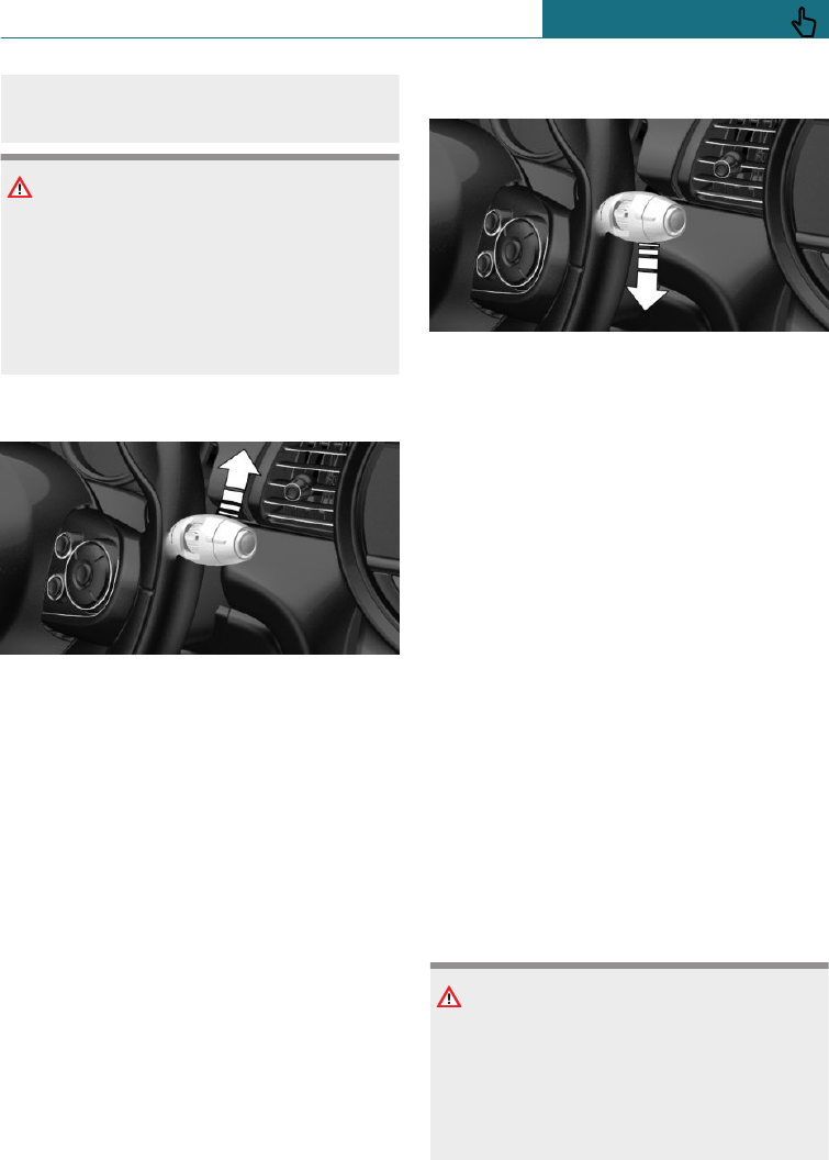
screen, and that the wipers are in contact
with the windscreen when switching on.
NOTE
If the wipers are frozen to the windscreen,
switching them on may cause the wiper
blades to tear off and the wiper motor to
overheat. There is a danger of damage to
property. Defrost the windscreen before
switching on the wipers.
Switching on
Tap the lever up or push it beyond the re-
sistance point.
–Normal wiping speed: press upwards
once.
When the vehicle is at a standstill, the
wipers switch to intermittent operation.
–Rapid wiping speed: press upwards
twice or press once beyond the resist-
ance point.
When the vehicle is at a standstill, the
wipers switch to normal speed.
The lever returns to the home position
when released.
Switching off and flick-wiping
Press the lever down.
–Switching off fast wiping speed: press
downwards twice.
–Switching off normal wiping speed:
press downwards once.
–To flick-wipe: press downwards once.
The lever returns to the home position
when released.
Intermittent mode or rain sensor
Principle
The rain sensor automatically controls the
wiper operation depending on the rain in-
tensity.
General
The sensor is mounted on the windscreen,
directly in front of the rearview mirror.
Without rain sensor, the interval for the
wiper operation is specified.
Safety note
NOTE
In car washes, the wipers may inadver-
tently start moving if the rain sensor is ac-
tivated. There is a danger of damage to
property. Deactivate the rain sensor in car
washes.
Seite 111
Driving CONTROLS
111
Online Edition for Part no. 01402988211 - II/18
Draft
from BA-76
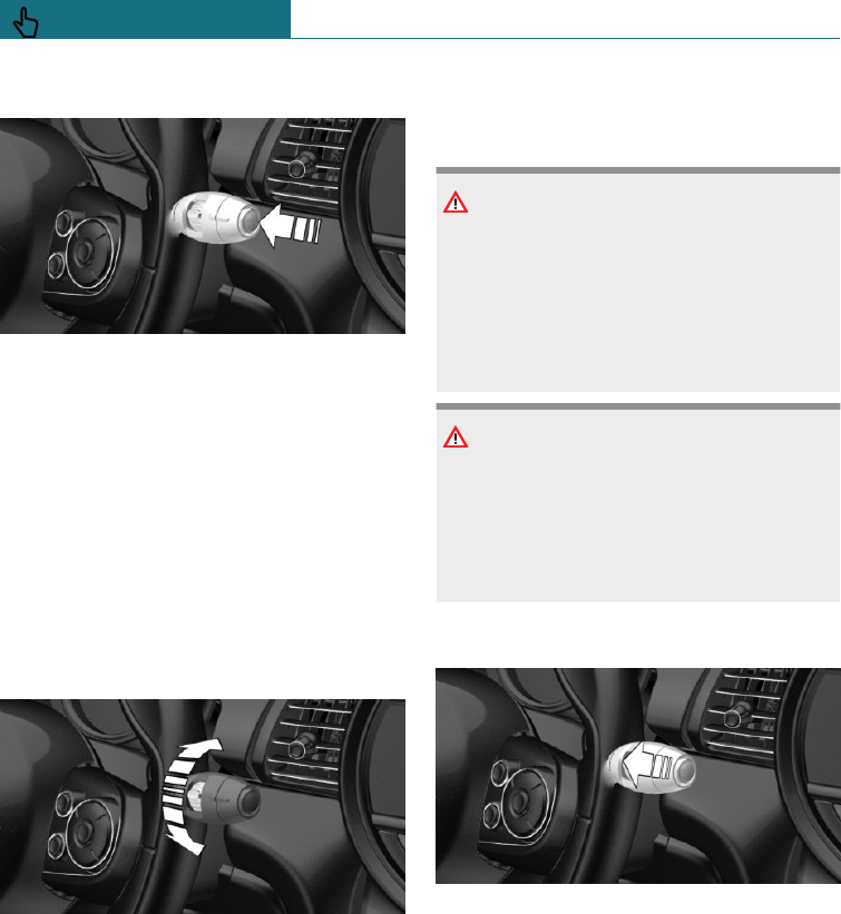
Activating/deactivating
Press the button on the wiper lever.
Wiping is started.
The LED in the wiper lever is illuminated.
If there is frost, a wiping process may not
be started.
If the journey is interrupted when the rain
sensor is switched on: if the journey is con-
tinued within about 15 minutes, the rain
sensor is reactivated automatically.
Setting the interval time or sensitivity
of the rain sensor
Turn the knurled wheel to set the interval
time or sensitivity of the rain sensor.
Up: short interval or high sensitivity of the
rain sensor.
Down: long interval or low sensitivity of the
rain sensor.
Windscreen washer
Safety notes
WARNING
At low temperatures, the washer fluid can
freeze onto the windscreen and restrict
visibility. There is a danger of accidents.
Only use the washer systems if there is no
possibility of the washer fluid freezing.
Use antifreeze if required.
NOTE
If the washer fluid reservoir is empty, the
washer pump cannot operate as intended.
There is a danger of damage to property.
Do not use the washer system with the
washer fluid reservoir empty.
To clean the windscreen
Pull the lever.
Fluid from the washer fluid reservoir is
sprayed onto the windscreen and the wipers
are operated briefly.
Windscreen washer jets
Both windscreen washer jets are automati-
cally heated when the ignition is switched
on.
Seite 112
CONTROLS Driving
112 Online Edition for Part no. 01402988211 - II/18
Draft
from BA-76
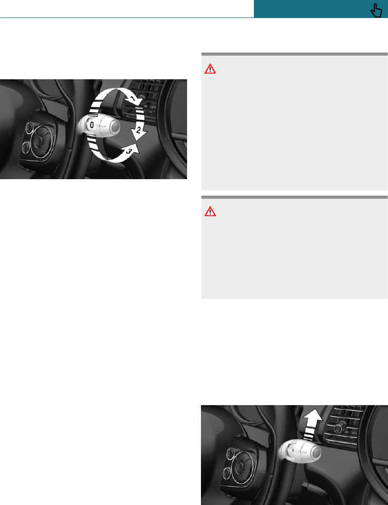
Rear wiper
Overview
Switching on rear window wiper
Turn the outer switch upwards.
–Rest position of the wiper, position 0.
–Intermittent operation, arrow 1: engag-
ing reverse gear activates continuous
operation.
Cleaning rear window
Turn the outer switch in the desired direc-
tion.
–In rest position: turn the switch down-
ward, arrow 3. The switch automatically
returns to its rest position when re-
leased.
–In intermittent operation: turn the
switch further, arrow 2. The switch au-
tomatically returns to its intermittent
position when released.
Fold-out position of the wipers
Principle
In the fold-out position, the wipers can be
folded away from the windscreen.
General
Helpful, for example for replacing the wiper
blades or folding them out in the event of
frost.
Safety notes
WARNING
If the wipers start moving when they are
folded away from the windscreen, parts of
the body may become trapped or the vehi-
cle may be damaged. There is a danger of
injury or damage to property. Make sure
that the vehicle is switched off when the
wipers are folded away from the wind-
screen, and that the wipers are in contact
with the windscreen when switching on.
NOTE
If the wipers are frozen to the windscreen,
switching them on may cause the wiper
blades to tear off and the wiper motor to
overheat. There is a danger of damage to
property. Defrost the windscreen before
switching on the wipers.
Folding out the wipers
1. Switch ignition on and back off again.
2. Press the wiper lever upwards beyond
the resistance point and hold it there for
approximately 3 seconds until the wip-
ers come to a standstill in a nearly verti-
cal position.
Seite 113
Driving CONTROLS
113
Online Edition for Part no. 01402988211 - II/18
Draft
from BA-76
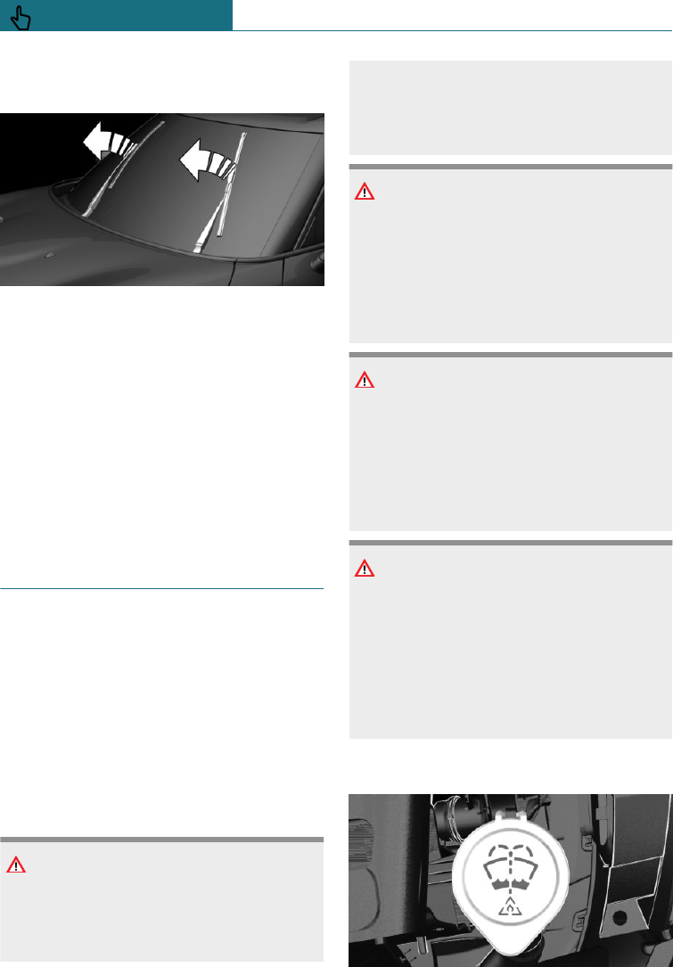
3. Lift the wipers completely away from
the windscreen.
Folding in the wipers
After folding the wipers in, the wiper sys-
tem must be reactivated.
1. Folding in the wipers completely onto
the windscreen.
2. Switch on the ignition.
3. Press the wiper lever downwards. The
wipers move back to the rest position
and are operational once again.
Washer fluid
General
All washer jets are supplied from one tank.
Use a mixture of tap water and screenwash
concentrate for the windscreen washer sys-
tem, if necessary with the addition of anti-
freeze.
Recommended minimum fill level: 1 litre,
approximately 1.7 Imp. pints.
Safety notes
WARNING
Some antifreezes can contain toxic sub-
stances, and are flammable. There is a risk
of fire and fatal injury. Comply with the in-
structions on the containers. Keep anti-
freezes away from sources of combustion.
Do not pour service products into other
bottles. Keep service products out of the
reach of children.
WARNING
Washer fluid can ignite on contact with
hot parts of the engine, and catch fire.
There is a danger of injury or damage to
property. Only top up washer fluid when
the engine has cooled down. Then fully
close the cap of the washer fluid reservoir.
NOTE
Additives containing silicone added to the
washer fluid for their water beading effect
on the windows may damage the washer
system. There is a danger of damage to
property. Do not add any additives con-
taining silicone to the washer fluid.
NOTE
Mixing different screenwash concentrates
or antifreezes can result in damage to the
washer system. There is a danger of dam-
age to property. Do not mix different
screenwash concentrates or antifreezes.
Comply with the instructions and mixing
ratios stated on the containers.
Overview
Seite 114
CONTROLS Driving
114 Online Edition for Part no. 01402988211 - II/18
Draft
from BA-76
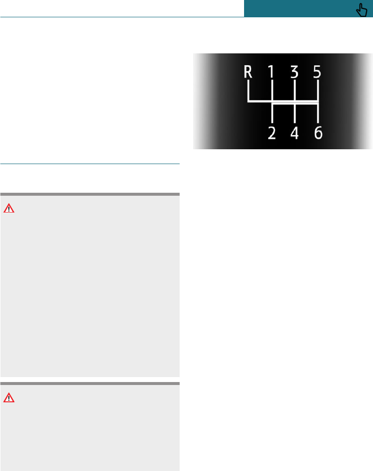
The reservoir for the washer fluid is located
in the engine compartment.
Malfunction
Using undiluted screenwash concentrate or
antifreeze made of alcohol may result in
false indications at low temperatures below
-15 ℃/+5 ℉.
Manual gearbox
Safety notes
WARNING
An unsecured vehicle can start moving
and rolling away. There is a danger of acci-
dents. Before leaving the vehicle, secure it
to prevent it from rolling away.
Observe the following to ensure that the
vehicle is secured against rolling away:
–Apply the parking brake.
–Turn the front wheels towards the
kerb on upward or downward gradi-
ents.
–Additionally secure the vehicle on up-
ward or downward gradients, for ex-
ample with a chock.
NOTE
When shifting into a lower gear, high en-
gine speeds can damage the engine. There
is a danger of damage to property. Push
the shift lever to the right while shifting
into the 5th or 6th gear.
Schematic diagram
–1 – 6: forward gears
–R: reverse gear
Shifting gears
General
Depending on the engine version, the en-
gine speed is automatically adjusted as re-
quired during a gear shift for a harmonious
and dynamic gear change.
Reverse gear
Engage this position only when the vehicle
is stationary.
To overcome the resistance, move the shift
lever firmly to the left towards the left and
engage the reverse gear with a gear shift
movement forwards.
Rolling or pushing the vehicle
In some situations, the vehicle is to roll
without its own power, for example in a car
wash, or be pushed.
1. Switch on the ignition.
2. Press the clutch and change out of a for-
ward gear or reverse.
3. Release the parking brake.
Seite 115
Driving CONTROLS
115
Online Edition for Part no. 01402988211 - II/18
Draft
from BA-76
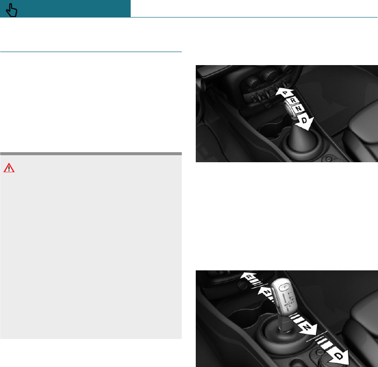
Steptronic transmission
Principle
The Steptronic transmission combines the
functions of an automatic transmission with
the opportunity of changing gear manually
if required.
Safety note
WARNING
An unsecured vehicle can start moving
and rolling away. There is a danger of acci-
dents. Before leaving the vehicle, secure it
to prevent it from rolling away.
Observe the following to ensure that the
vehicle is secured against rolling away:
–Apply the parking brake.
–Turn the front wheels towards the
kerb on upward or downward gradi-
ents.
–Additionally secure the vehicle on up-
ward or downward gradients, for ex-
ample with a chock.
Selector lever version
General
Depending on the equipment, a transmis-
sion with either a latching selector lever or
a tap-operated selector lever is installed.
Transmission with a latching selector
lever
The selector lever positions P, R, N and D
are selected by moving the selector lever
into the respective selector lever position.
The selector lever engages in the selector
lever positions.
Transmission with a tap-operated
selector lever
The selector lever positions P, R, N and D
are selected by tapping the selector lever
forwards or back. The selector lever returns
to the middle position when released.
Selector lever position P is automatically
engaged, see page 117, in the following sit-
uations.
Selector lever positions
D drive position
Selector lever position for all normal driv-
ing. All gears for forward driving are selec-
ted automatically.
Seite 116
CONTROLS Driving
116 Online Edition for Part no. 01402988211 - II/18
Draft
from BA-76

R Reverse
Only engage selector lever position R when
the vehicle is stationary.
N neutral
In selector lever position N, the vehicle can
be pushed or can roll without power from
the engine, for example in car washes, see
page 119.
P Park
General
Selector lever position for parking the vehi-
cle, for example.
In selector lever position P, the transmis-
sion blocks the drive wheels.
Only engage selector lever position P when
the vehicle is stationary.
Before leaving the vehicle, ensure that the
selector lever is engaged in the P position.
The vehicle could otherwise start to move.
Automatic parking position for a
transmission with a tap-operated selector
lever
Selector lever position P is automatically
engaged in the following situations, for ex-
ample:
–After stopping the engine in the radio
ready state, see page 103, or ignition
off, see page 102, when selector lever
position R, D or M/S is engaged.
–If, while the vehicle is at a standstill and
selector lever position D, M/S or R is en-
gaged, the driver's seat belt is unfas-
tened, the driver's door is opened and
the brake pedal is not depressed.
–After switching off the ignition, if selec-
tor lever position N is engaged.
Engaging selector lever positions:
with a latching selector lever
General
Apply the brakes until you are ready to
drive off, otherwise the vehicle will move
when a drive position is selected.
Operating requirements
The selector lever can only be taken out of
the selector lever position P when the igni-
tion is switched on or the engine is running.
Engaging selector lever position D, N,
R or P
Before shifting from selector lever posi-
tion P or N when the vehicle is stationary,
first depress the brake pedal, otherwise the
shift lock will not be deactivated and the de-
sired gearshift will not be performed.
A selector lever lock prevents the following
incorrect operation:
–Inadvertent shifting to selector lever po-
sition P or R.
–Inadvertent change from selector lever
position P to another selector lever posi-
tion.
1. To cancel the selector lever lock: with
the brake pedal pressed, press the but-
ton on the front of the selector lever.
Seite 117
Driving CONTROLS
117
Online Edition for Part no. 01402988211 - II/18
Draft
from BA-76
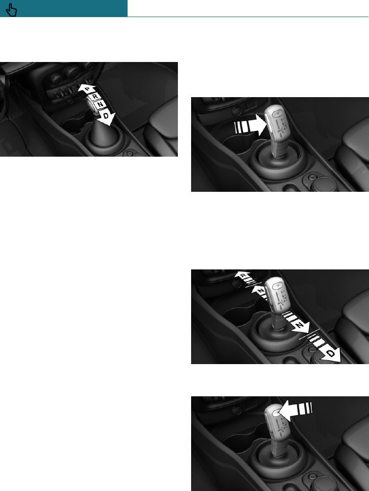
2. Move the selector lever to the desired
position.
Engaging selector lever positions:
with a tap-operated selector lever
General
Apply the brakes until you are ready to
drive off, otherwise the vehicle will move
when a drive position is selected.
Operating requirements
A change from selector lever position P to
another selector lever position only takes
place when the brake pedal is pressed.
Depending on the transmission version, the
engine may have to be running too.
Engaging selector lever positions D, N,
R
A selector lever lock prevents the following
incorrect operation:
–Inadvertent shifting to selector lever po-
sition R.
–Inadvertent change from selector lever
position P to another selector lever posi-
tion.
1. Press and hold the button to cancel the
selector lever lock.
2. With the driver's seat belt fastened,
briefly press the selector lever in the de-
sired direction, possibly overcoming a
resistance point. The selector lever re-
turns to the middle position when re-
leased.
Engaging selector lever position P
Press the button P.
Seite 118
CONTROLS Driving
118 Online Edition for Part no. 01402988211 - II/18
Draft
from BA-76
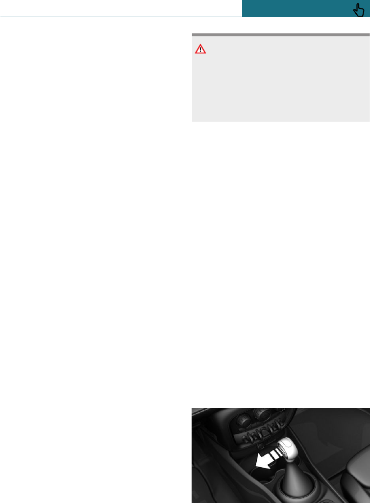
Rolling or pushing the vehicle
General
In some situations, the vehicle may need to
be rolled a short distance without power,
for example in a car wash, or be pushed.
Engaging selector lever position N:
with a latching selector lever
1. Switch on the ignition.
2. If necessary, release the parking brake.
3. Depress the brake pedal.
4. Touch the selector lever lock and en-
gage selector lever position N.
5. Release brakes.
The vehicle can now roll.
If there is a fault, it may not be possible to
change the selector lever position.
Unlock the transmission lockout manually,
see page 121, if necessary.
Engaging selector lever position N:
with a tap-operated selector lever
1. Start the engine with the brake pedal
depressed.
2. If necessary, release the parking brake.
3. Depress the brake pedal.
4. Touch the selector lever lock and en-
gage selector lever position N.
5. Stop the engine.
In this way the ignition remains
switched on and a Check Control mes-
sage is displayed.
The vehicle can now roll.
NOTE
Selector lever position P is automatically
engaged when the ignition is switched off.
There is a danger of damage to property.
Do not switch the ignition off in car
washes.
Irrespective of the ignition, the selector
lever position P is engaged automatically af-
ter approximately 15 minutes.
If there is a fault, it may not be possible to
change the selector lever position.
Unlock the transmission lockout electroni-
cally if necessary, see page 122.
Kick-down
Kick-down enables you to achieve maxi-
mum performance. Press the accelerator
pedal down beyond the regular full-throttle
position; resistance will be felt.
Sport program M/S
Principle
In the sport programme, the gear shift
points and gear shift times are configured
for more sporty driving. For example, the
transmission shifts up later and the gear-
shift times are shorter.
Activating the sport programme
Press the selector lever out of selector lever
position D to the left.
Seite 119
Driving CONTROLS
119
Online Edition for Part no. 01402988211 - II/18
Draft
from BA-76
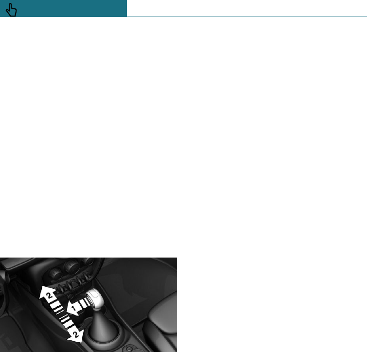
The gear selected appears on the instru-
ment cluster, for example S1.
The sport programme of the gearbox is acti-
vated.
Exiting sport programme
Press the selector lever to the right.
D is shown in the instrument cluster.
Manual operation M/S
Principle
The gears can be changed manually in man-
ual operation.
Activating manual operation
1. Press the selector lever from selector
lever position D to the left, arrow 1.
2. Press the selector lever forwards or pull
it backwards, arrows 2.
Manual operation M/S becomes active and
the gear is shifted.
The gear selected appears on the instru-
ment cluster, for example M1.
Shifting gears
–To shift down: press the selector lever
forwards.
–To shift up: press the selector lever
backwards.
In certain situations, the Steptronic trans-
mission continues to shift automatically, for
example when certain engine speed limits
are reached.
With a tap-operated selector lever: when
M2 is set manually while the vehicle is sta-
tionary, the transmission will no longer
shift back to M1. This shifting behaviour is
retained until you engage M1 manually or
exit M.
Avoiding automatically changing up
If certain engine speed limits are reached, it
is automatically upshifted as needed in
manual operation M/S.
MINI John Cooper Works: when reaching
certain engine speed limits, up-shifting is
not performed automatically in manual op-
eration M/S.
With the Steptronic sport transmission,
these automatic shift processes are not car-
ried out, if one of the following conditions
is met:
–DSC is deactivated.
–TRACTION is activated.
In addition, there is no down shift for kick-
down.
In the corresponding gearbox version, oper-
ating the kick-down and the left shift paddle
at the same time allows you to change down
to the lowest possible gear. This is not pos-
sible in a brief change from selector lever
position D to manual operation M/S using
the shift paddles.
Exiting manual operation
Press the selector lever to the right.
D is shown in the instrument cluster.
Seite 120
CONTROLS Driving
120 Online Edition for Part no. 01402988211 - II/18
Draft
from BA-76
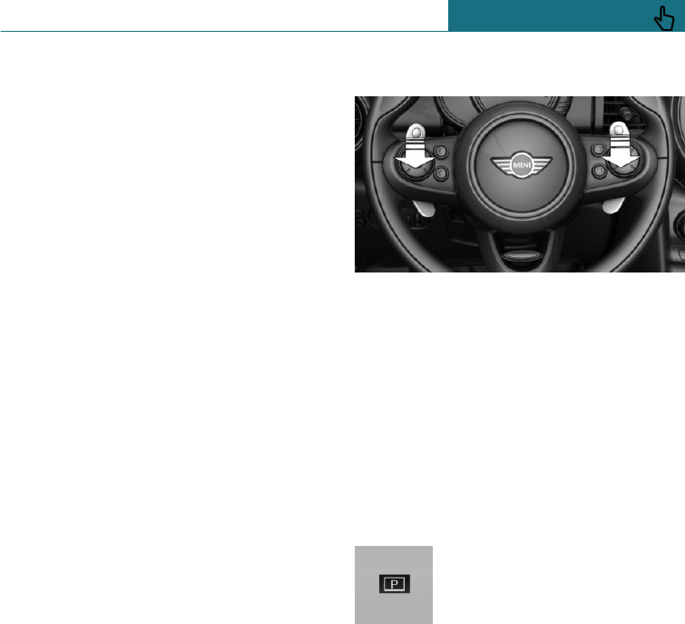
Shift paddles with Steptronic sport
transmission
Principle
The shift paddles on the steering wheel ena-
ble fast gearshifting without taking the
hands off the steering wheel.
General
Gearshift
Gear shifting is only carried out if the en-
gine speed and vehicle speed are appropri-
ate, for example, the transmission will not
shift down if the engine speed is too high.
Short-term manual operation
In selector lever position D, operating a
shift paddle causes the system to switch to
manual operation temporarily.
The gearbox reverts to automatic operation
from manual operation after a certain period
of time of moderate driving without acceler-
ation or gear shifts using the shift paddles.
Changing to automatic operation is possible
as follows:
–Pull and hold right shift paddle.
–In addition to briefly pulling right shift
paddle, briefly pull left shift paddle.
Permanent manual operation
In selector lever position S, operating a shift
paddle causes the system to switch perma-
nently to manual operation (mode).
Shifting gears
–Change up: pull right shift paddle
briefly.
–Change down: pull left shift paddle
briefly.
–Pull and hold left shift paddle to shift to
the lowest possible gear.
The gear selected appears briefly on the in-
strument cluster, followed by the gear cur-
rently in use.
Displays in the instrument cluster
The selector lever position is
displayed, for example P.
Releasing the transmission lockout
manually: with a latching selector
lever
If the selector lever is blocked in selector
lever position P in spite of the ignition be-
ing switched on, the brake pedal depressed
and button pressed on the selector lever,
the transmission lockout can be unlocked
manually:
Before transmission lockout is released
manually, apply parking brake to prevent
vehicle from rolling away.
1. Release the sleeve from the selector
lever, together with the lower holding
ring, from the centre console. To do this,
Seite 121
Driving CONTROLS
121
Online Edition for Part no. 01402988211 - II/18
Draft
from BA-76
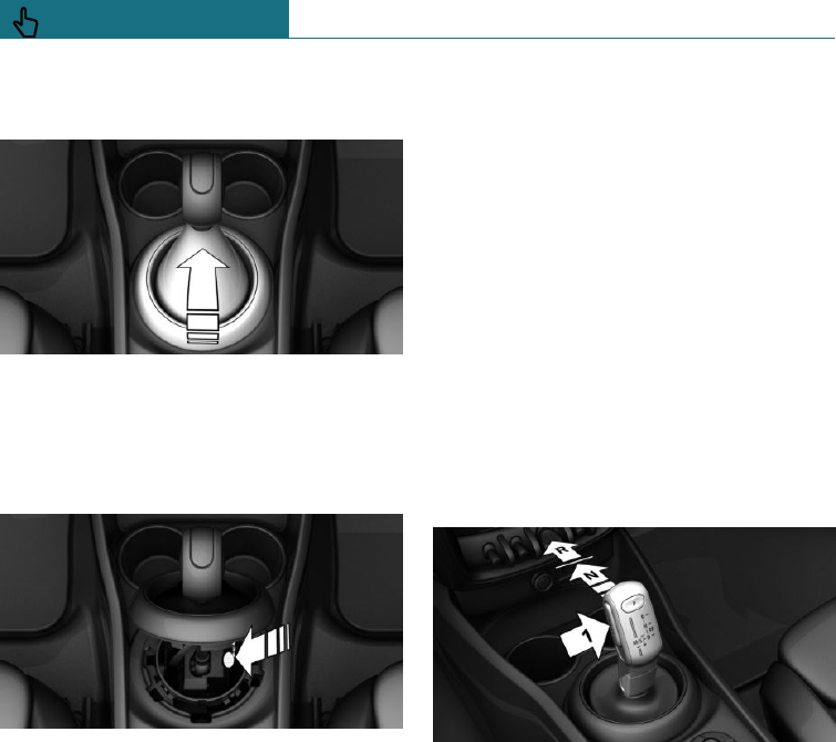
pull the holding ring upwards at the rear
edge.
2. Lift the sleeve. Remove the cable plug
connector as appropriate.
3. With the screwdriver from the on-board
tool kit, see page 305, push the yellow
release lever down, see arrow.
4. Press the button on the front of the se-
lector lever and move the selector lever
back slightly.
Release the release lever.
5. Put the selector lever in the desired po-
sition.
More information can be found in the Tow-
starting and towing chapter.
Releasing the transmission lockout
electronically: with a tap-operated
selector lever
General
Unlock the transmission lockout electroni-
cally to manoeuvre the vehicle out of a dan-
ger area.
Before the transmission lockout is released,
apply the parking brake to prevent the vehi-
cle from rolling away.
Engaging selector lever position N
Unlocking is possible if the starter can turn
the engine.
1. Apply the brakes and keep them applied.
2. Press the start/stop button. The starter
must be heard to start turning.
3. Press the button on the selector lever,
arrow 1, push the selector lever to selec-
tor lever position N and hold it there, ar-
row N, until selector lever position N is
displayed in the instrument cluster.
A Check Control message is shown.
4. Release the selector lever.
5. Release the brake as soon as the starter
stops.
6. Manoeuvre the vehicle out of the danger
area and then secure it against rolling
away.
More information can be found in the Tow-
starting and towing chapter.
Steptronic sport transmission:
Launch Control
Principle
When the ambient conditions are dry,
Launch Control permits optimised accelera-
tion on a road surface that offers plenty of
grip.
Seite 122
CONTROLS Driving
122 Online Edition for Part no. 01402988211 - II/18
Draft
from BA-76

General
Use of Launch Control causes premature
component wear, as the function subjects
the vehicle to very high stresses and loads.
Do not use Launch Control when running
in, see page 220.
To start with Launch Control, do not turn
the steering wheel.
Operating requirements
Launch Control is available as soon as the
engine and transmission are at operating
temperature.
Depending on the outside temperature and
driving style, the engine and transmission
require an uninterrupted journey of up to
50 km, 30 miles in order to reach the oper-
ating temperature needed for Launch Con-
trol.
Starting with Launch Control
With the engine running:
1. Press the button and select
SPORT with the MINI Driving Modes
switch.
In the instrument cluster, TRACTION is
shown in combination with SPORT. The
DSC OFF indicator lamp is illuminated.
2. Engaging selector lever position S.
3. Press the brake firmly with the left foot.
4. Press the accelerator pedal down beyond
the resistance at the full-throttle posi-
tion and hold, kick-down.
A flag symbol is shown in the instru-
ment cluster.
5. The starting engine speed is adjusted.
Release the brake within 3 seconds.
Using again during a journey
Once Launch Control has been used, the
transmission requires approximately 5 mi-
nutes to cool down before Launch Control
can be used again.
After using Launch Control
To support driving stability, re-activate Dy-
namic Stability Control, DSC.
System limits
An experienced driver may be able to ach-
ieve better acceleration values in DSC OFF
mode.
Seite 123
Driving CONTROLS
123
Online Edition for Part no. 01402988211 - II/18
Draft
from BA-76
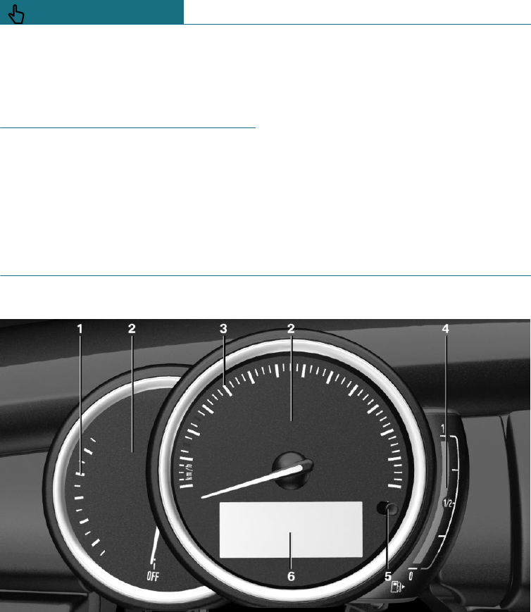
Displays
Vehicle equipment
This chapter describes all standard, country-
specific and special equipment available for
the model series. Therefore equipment
which is not installed in your vehicle, for
example on account of the optional equip-
ment selected or the country specification,
may also be described here. This also ap-
plies to safety-relevant functions and sys-
tems. Comply with the relevant laws and
regulations when using the corresponding
functions and systems.
Instrument cluster
Overview
1Revolution counter 129
2Indicator and warning lamps
3Speedometer
4Fuel gauge 129
5Display/reset kilometres 129
6Electronic displays 125
Seite 124
CONTROLS Displays
124 Online Edition for Part no. 01402988211 - II/18
Draft
from BA-76
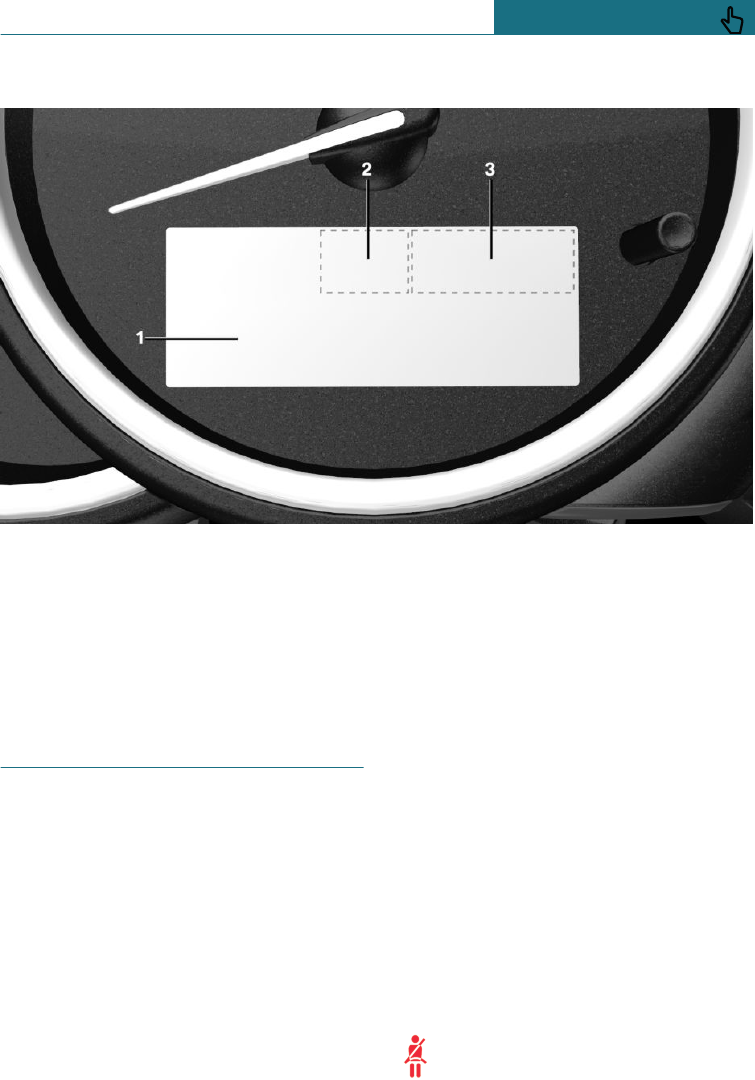
Electronic displays
1Driver Assistance Systems
Messages, for example, Check Control
Time 130
Outside temperature 130
Selection lists 135
Odometer/trip distance recorder 129
On-board computer 135
2Selector lever position 116
Shift point indicator 133
3Status of MINI Driving Modes
switch 172
Check Control
Principle
The Check Control monitors vehicle func-
tions and alerts you to any faults in the
monitored systems.
General
A Check Control message is displayed as a
combination of indicator or warning lamps
and text messages in the instrument cluster.
If applicable, the text message shown in the
Control Display is accompanied by an addi-
tional acoustic signal.
Indicator and warning lamps
General
Indicator and warning lamps can illuminate
in a variety of combinations and colours.
When the engine starts or the ignition is
switched on, the functionality of some
lights is checked and they illuminate briefly.
Red lights
Seat belt reminder
The driver's side seat belt is not fas-
tened. For some country specifica-
tions: the front passenger seat belt is
Seite 125
Displays CONTROLS
125
Online Edition for Part no. 01402988211 - II/18
Draft
from BA-76
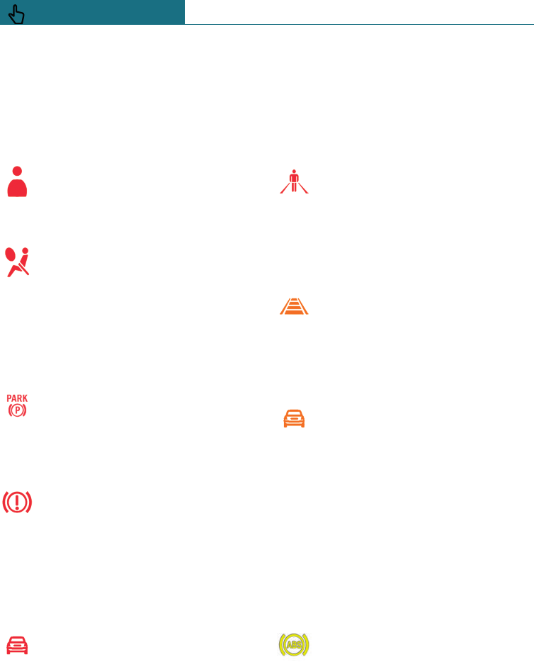
not fastened or objects are detected on the
front passenger seat.
Check whether the seat belt has been fas-
tened correctly.
Seat belt reminder for rear seats
Seat belt on the corresponding rear
seat is not fastened.
Airbag system
Airbag system and belt tensioner
may be faulty.
Immediately have the vehicle
checked by a Service Partner of the manu-
facturer or another qualified Service Partner
or a specialist workshop.
Parking brake
The parking brake is engaged.
Release the parking brake, see
page 109.
Brake system
Brake system malfunctioning. Con-
tinue driving at moderate speed.
Immediately have the vehicle
checked by a Service Partner of the manu-
facturer or another qualified Service Partner
or a specialist workshop.
Front-end collision warning
Indicator lamp is illuminated: ad-
vance warning, for example if a dan-
ger of collision is anticipated or
there is a very short distance to a vehicle
ahead.
Increase the distance.
Indicator lamp flashes: acute warning indi-
cating a risk of an immediate collision risk
because the vehicle is approaching another
vehicle and the differential speed is rela-
tively high.
Intervene by braking and, if necessary, per-
forming an evasive manoeuvre.
Person warning
If there is a risk of collision with a
detected person, the symbol illumi-
nates and a signal sounds.
Orange lights
Active Cruise Control
The number of transverse bars
shows the selected distance to the
vehicle in front.
Camera-based Cruise Control, see page 175.
Vehicle recognition, Active Cruise Control
Indicator lamp is illuminated: system
has detected a vehicle ahead.
Indicator lamp flashes: the require-
ments for operation of the system are no
longer being met.
The system has been deactivated but will
continue to brake until you actively take
over by depressing the brake or the acceler-
ator pedal.
Yellow lights
Anti-lock Brake System, ABS
Braking force boost may be faulty.
Avoid sudden braking. Take into ac-
count that the braking distance will
be longer.
Have the vehicle checked immediately by a
Service Partner of the manufacturer or an-
other qualified Service Partner or a special-
ist workshop.
Seite 126
CONTROLS Displays
126 Online Edition for Part no. 01402988211 - II/18
Draft
from BA-76
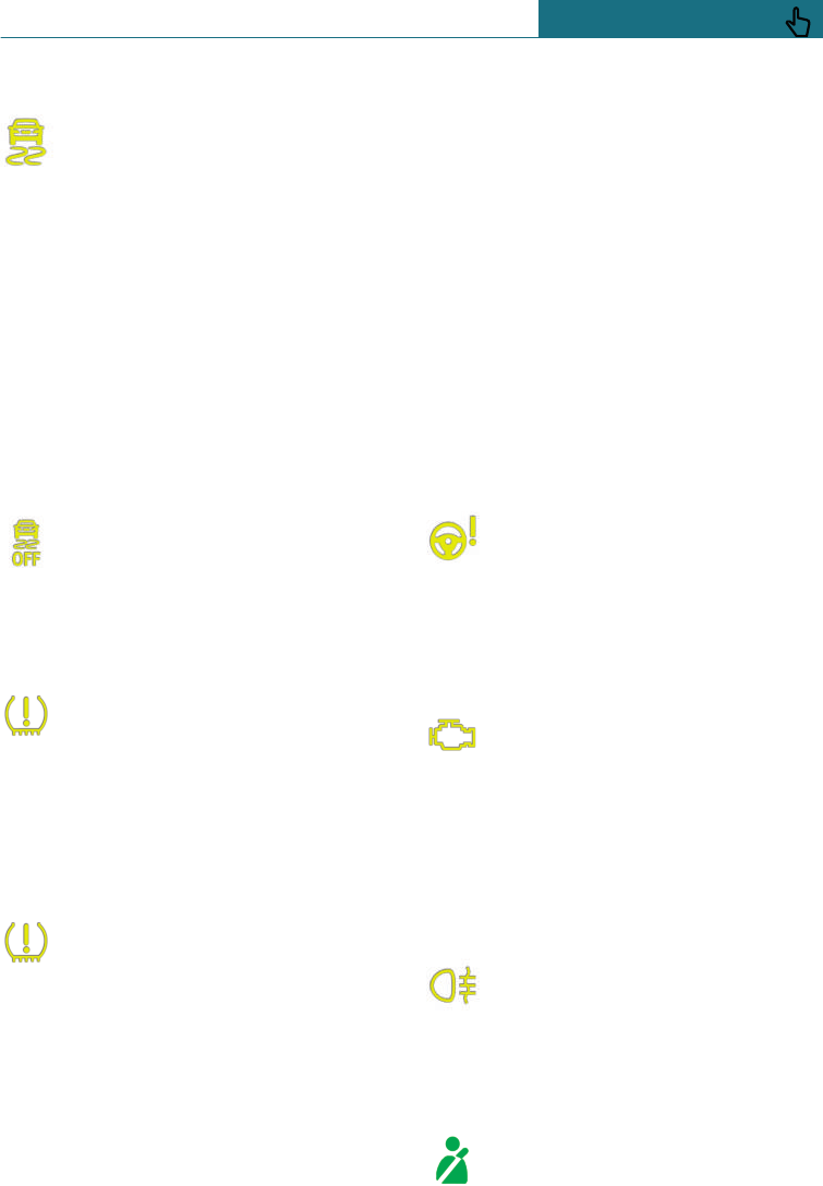
Dynamic Stability Control DSC
If the indicator lamp is flashing: DSC
is regulating the acceleration and
braking forces. The vehicle is being
stabilised. Decrease speed and adjust driv-
ing style to the road conditions.
If the indicator lamp is illuminated: DSC has
failed.
Have the system checked by a Service Part-
ner of the manufacturer or another qualified
Service Partner or a specialist workshop.
DSC, see page 170.
Dynamic Stability Control DSC
deactivated, or Dynamic Traction Control
DTC activated
DSC is deactivated or DTC is activa-
ted.
DSC, see page 170, and DTC, see
page 171.
Runflat indicator RPA
The runflat indicator reports a loss of
tyre inflation pressure in a tyre.
Reduce your speed and carefully
stop the vehicle. Avoid violent or sudden
braking and steering manoeuvres.
Runflat indicator, see page 157.
Tyre Pressure Monitor TPM
The indicator lamp illuminates: the
Tyre Pressure Monitor is reporting a
low tyre inflation pressure or a flat
tyre. Note the information in the Check Con-
trol message.
The indicator lamp flashes and then illumi-
nates continuously: no flat tyres or loss of
tyre inflation pressure can be detected.
–Fault due to systems or devices with the
same radio frequency: the system is au-
tomatically reactivated upon leaving the
field of interference.
–TPM could not complete the reset: per-
form a system reset again.
–A wheel without TPM wheel electronics
is fitted: have it checked by a Service
Partner of the manufacturer or another
qualified Service Partner or a specialist
workshop if necessary.
–Malfunction: have the system checked
by a Service Partner of the manufacturer
or another qualified Service Partner or a
specialist workshop.
Tyre Pressure Monitor, see page 152.
Steering system
Steering system faulty.
Have the system checked by a Serv-
ice Partner of the manufacturer or
another qualified Service Partner or a spe-
cialist workshop.
Emissions
Engine function malfunctioning.
Have the vehicle checked by a Serv-
ice Partner of the manufacturer or
another qualified Service Partner or a spe-
cialist workshop.
Socket for on-board diagnosis, see
page 303.
Rear fog lights
Rear fog lights are switched on.
Rear fog lights, see page 145.
Green lights
Seat belt reminder for rear seats
Green: seat belt fastened on the cor-
responding rear seat.
Seite 127
Displays CONTROLS
127
Online Edition for Part no. 01402988211 - II/18
Draft
from BA-76
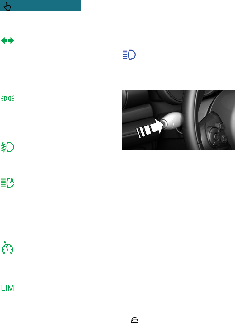
Turn indicator
The turn indicator is switched on.
If the indicator lamp flashes more
rapidly than usual, a turn signal light
has failed.
Turn indicators, see page 110.
Side lights, driving lights
The side lights or driving lights are
switched on.
Side lights / low-beam headlights,
driving lights control, see page 141.
Front fog lights
Front fog lights are switched on.
Front fog lights, see page 145.
High-beam assistance
High-beam assistance is switched
on.
The high-beam headlights are
switched on and off automatically depend-
ing on the traffic situation.
High-beam assistance, see page 144.
Cruise Control
The system is switched on. The
speed set using the controls on the
steering wheel is maintained.
Manual speed limiter
Indicator lamp is illuminated: system
is switched on.
Indicator lamp flashes: set speed
limit is exceeded. An acoustic signal may
sound.
Reduce speed or deactivate system.
Blue lights
High-beam headlights
The high-beam headlights are
switched on.
High-beam headlights, see page 110.
Hiding Check Control messages
Press the button on the turn indicator lever.
Continuous display
Some Check Control messages are displayed
permanently and remain until the fault has
been repaired. If there are a number of mal-
functions simultaneously, the messages are
displayed in succession.
The messages can be hidden for approxi-
mately 8 seconds. They are then displayed
again automatically.
Temporary display
Some Check Control messages are automati-
cally hidden after approximately 20 sec-
onds. The Check Control messages remain
saved and can be displayed again.
Displaying Check Control messages
saved in the memory
Using the on-board monitor:
1. "My MINI"
2. "Vehicle status"
Seite 128
CONTROLS Displays
128 Online Edition for Part no. 01402988211 - II/18
Draft
from BA-76
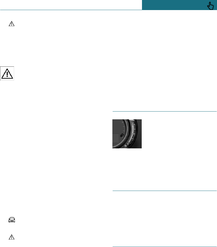
3. "Check Control"
4. Select a text message.
Display
Check Control
At least one Check Control message
is displayed or saved.
Text messages
Text messages and symbols in the instru-
ment cluster explain the meaning of a
Check Control message and the indicator
and warning lamps.
Supplementary text messages
You can call up additional information, for
example the cause of the fault and any ac-
tion required, via Check Control.
The supplementary text is automatically
shown in the Control Display for urgent
messages.
Additional assistance
It is possible to select additional assistance
depending on the Check Control message.
Using the on-board monitor:
1. "My MINI"
2. "Vehicle status"
3. "Check Control"
4. Select the required text message.
5. Select the desired setting.
–"Owner's Handbook"
Display additional information on
the Check Control message in the
Integrated Owner's Handbook.
–"Service request"
Contact a Service Partner of the
manufacturer or another qualified
Service Partner or a specialist work-
shop.
–"MINI Roadside Assistance"
Contact breakdown assistance.
Messages displayed at the end of
a journey
Certain messages displayed when driving
are displayed again when the ignition is
switched off.
Fuel gauge
The arrow next to the petrol
pump symbol shows on which
side of the vehicle the petrol
tank flap is.
The angle of the vehicle may
cause the display to fluctuate.
Notes on refuelling, see page 268.
Revolution counter
It is vital to avoid engine speeds in the red
warning zone. In this zone, the fuel supply
is interrupted to protect the engine.
Odometer and trip distance
recorder
Principle
The total distance driven and trip distance
since the last reset are displayed on the in-
strument cluster.
Seite 129
Displays CONTROLS
129
Online Edition for Part no. 01402988211 - II/18
Draft
from BA-76
Reset trip distance recorder
Press the button.
–When the ignition is off,
the odometer is displayed.
–When the ignition is on,
the trip distance recorder
is reset.
Outside temperature
General
If the display falls to +3 ℃/+37 ℉, a signal
sounds.
A Check Control message is shown.
There is an increased risk of black ice.
Safety note
WARNING
Even at temperatures above +3 ℃/+37 ℉,
there may be an increased risk of black
ice, for example on bridges or on shaded
roads. There is a danger of accidents. At
low temperatures, adjust the driving style
to the weather conditions.
Display
The outside temperature is
displayed in the instrument
cluster.
Time
The time is shown in the in-
strument cluster.
The time can be set using the
on-board monitor.
Date
The date is displayed on the
instrument cluster.
The date can be set using the
on-board monitor.
Range
General
If the remaining range is low:
–A Check Control message is briefly dis-
played.
–The on-board computer shows the re-
maining range.
–If a dynamic driving style is adopted, for
example fast cornering, engine function
is not always ensured.
If the range drops below approximately
50 km, approximately 30 miles the Check
Control message is continually displayed.
Safety notes
NOTE
If the range drops below 50 km, approxi-
mately 30 miles, the engine may no longer
be supplied with sufficient fuel. Engine
function is no longer ensured. There is a
Seite 130
CONTROLS Displays
130 Online Edition for Part no. 01402988211 - II/18
Draft
from BA-76
danger of damage to property. Refuel in
good time.
Display
The current range is shown in
the instrument cluster.
Displaying the range
Using the on-board monitor:
1. "My MINI"
2. "System settings"
3. "Displays"
4. "Instrument cluster"
5. "Range"
Current fuel consumption
Principle
Shows the momentary fuel consumption. It
is possible to check the economy and envi-
ronmental compatibility of your driving
style.
Displaying the current fuel
consumption
Using the on-board monitor:
1. "My MINI"
2. "System settings"
3. "Displays"
4. "Instrument cluster"
5. "Current consumption"
Service requirements
Principle
The function shows the current service re-
quirements and related maintenance jobs.
General
The distance or time remaining until the
next service is displayed briefly in the in-
strument cluster after the ignition is
switched on.
The current service requirements can be
read out from the remote control by a serv-
ice advisor.
Display
Detailed information on service
requirements
More detailed information on the scope of
maintenance can be displayed on the Con-
trol Display.
Using the on-board monitor:
1. "My MINI"
2. "Vehicle status"
3. "Service requirements"
Essential maintenance routines and any
statutory inspections required are dis-
played.
4. Select an entry to display more detailed
information.
Seite 131
Displays CONTROLS
131
Online Edition for Part no. 01402988211 - II/18
Draft
from BA-76
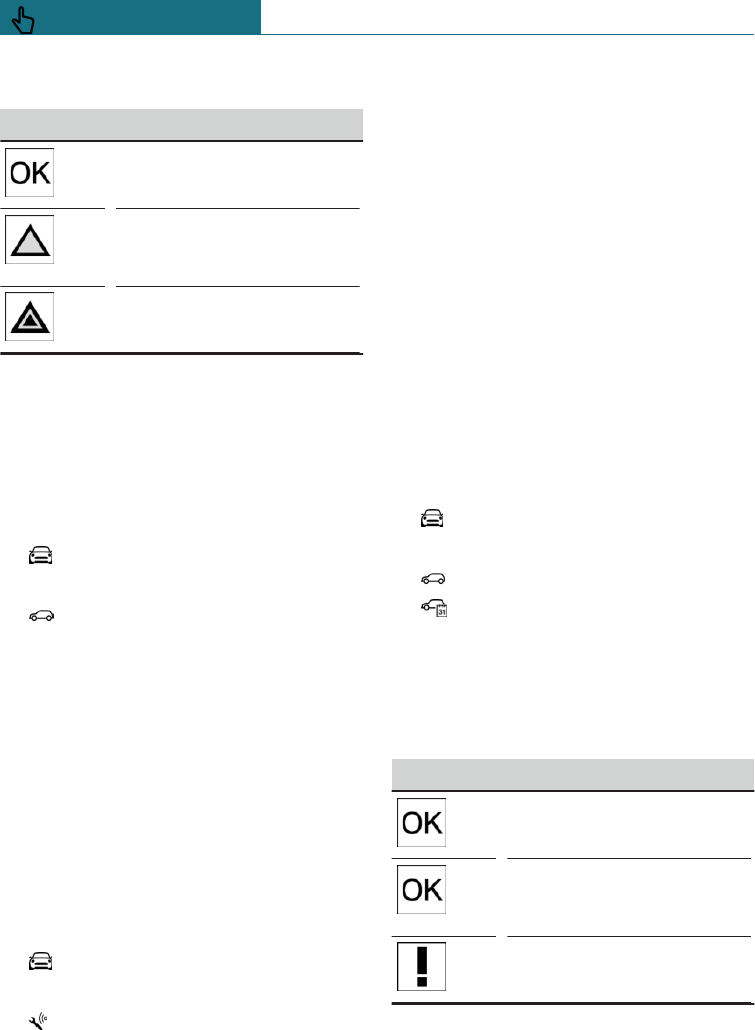
Symbols
Symbols Description
No servicing is currently
needed.
Maintenance or an inspec-
tion required by law is due
soon.
Servicing is overdue.
Entering deadlines
Enter deadlines for prescribed statutory ve-
hicle inspections.
Ensure that the date and time are set cor-
rectly in the vehicle.
Using the on-board monitor:
1. "My MINI"
2. "Vehicle status"
3. "Service requirements"
4. "Vehicle inspection"
5. "Date:"
6. Select the desired setting.
Automatic Service notification
Data on the service status or on statutory
inspections for the vehicle is transmitted to
the Service Partner automatically when a
service or inspection is imminent.
It is possible to check when the Service
Partner was notified.
Using the on-board monitor:
1. "My MINI"
2. "Vehicle status"
3. "Teleservice Call"
Service history
Principle
Maintenance that has been performed can
be displayed on the Control Display. This
function is available as soon as a mainte-
nance visit has been entered in the vehicle
data.
General
Have maintenance work performed by a
Service Partner of the manufacturer or an-
other qualified Service Partner or a special-
ist workshop. The maintenance work car-
ried out is documented in the vehicle data.
Displaying service history
Using the on-board monitor:
1. "My MINI"
2. "Vehicle status"
3. "Service requirements"
4. "Service history"
Performed maintenance is shown.
5. Select an entry to display more detailed
information.
Symbols
Symbols Description
Green: maintenance has
been carried out on time.
Yellow: maintenance has
been carried out later than
scheduled.
Maintenance has not been
carried out.
Seite 132
CONTROLS Displays
132 Online Edition for Part no. 01402988211 - II/18
Draft
from BA-76
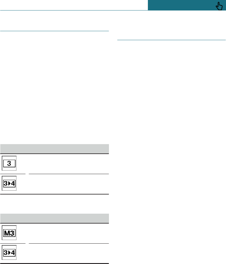
Shift point indicator
Principle
The system recommends the most efficient
gear for the current driving situation.
General
Depending on the equipment installed and
the country specifications, the shift point
indicator is active in the manual mode of
the Steptronic transmission and with the
manual gearbox.
Information on up or down shifting are dis-
played in the instrument cluster.
Manual gearbox: displays
Example Description
Most efficient gear is engaged.
Shift to a more efficient gear.
Steptronic transmission: displays
Example Description
Most efficient gear is engaged.
Shift to a more efficient gear.
Speed Limit Info with overtak-
ing restriction display
Speed Limit Info
Principle
Speed Limit Info shows the currently detec-
ted speed limit in the instrument cluster.
General
The camera in the area of the interior rear-
view mirror detects traffic signs at the edge
of the road as well as variable overhead
signs. Traffic signs with additional signs,
for example in wet conditions, are also de-
tected, compared with internal vehicle data,
for example of the rain sensor, and dis-
played, depending on the situation.
If a navigation system is not installed, the
system has certain technical limitations.
Only road signs with speed limits are detec-
ted and displayed. Speed limits when driv-
ing into and leaving built-up areas and mo-
torway signs, for example, are not displayed.
Speed limits with textual supplementary
signs are always shown.
Speed limits for towing a trailer are not
shown.
Overtaking restriction display
Principle
Overtaking restriction signs and end of re-
striction signs that are detected by the cam-
era are indicated by corresponding symbols
in the instrument cluster.
General
The system only considers no passing re-
strictions and ends of restrictions that are
indicated by means of signs.
Nothing will be displayed in the following
situations:
Seite 133
Displays CONTROLS
133
Online Edition for Part no. 01402988211 - II/18
Draft
from BA-76
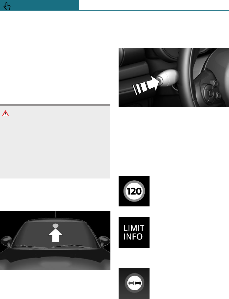
–In countries in which no passing is pri-
marily shown by road markings.
–On routes without signage.
–In the case of railway crossings, lane
markings and other situations which in-
dicate a no passing restriction but
which are not sign-posted to this effect.
No passing restrictions for towing a trailer
are not shown.
Safety note
WARNING
The system does not relieve you of your
personal responsibility to assess the visi-
bility conditions and traffic situation cor-
rectly. There is a danger of accidents.
Adapt your driving style to the traffic con-
ditions. Observe the traffic situation and
intervene actively if the situation warrants
it.
Overview
Camera
The camera is located on the front side of
the rearview mirror.
Keep the windscreen clean and clear in the
area in front of the rearview mirror.
Display
Speed Limit Info is displayed on the on-
board computer.
Press the button on turn indicator lever sev-
eral times if necessary.
The Speed Limit Info is shown in the infor-
mation display in the instrument cluster.
Overtaking restrictions are displayed to-
gether with Speed Limit Info.
Speed Limit Info
Last detected speed limit.
If no navigation system is in-
stalled, the traffic sign is
greyed out after turning off or
on longer sections of road.
Without navigation system:
no speed limit or end of re-
striction detected.
Overtaking restriction display
No passing restriction.
Seite 134
CONTROLS Displays
134 Online Edition for Part no. 01402988211 - II/18
Draft
from BA-76
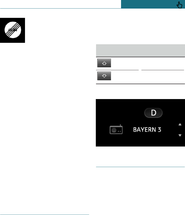
End of no passing restriction.
System limits
The function may be restricted and may dis-
play incorrect information in the following
situations, for example:
–In thick fog, wet conditions or snow.
–If signs are fully or partially obscured by
objects, stickers or paint.
–If the vehicle is moving too close to the
vehicle ahead.
–In the case of bright oncoming light or
strong reflections.
–When the windscreen in front of the
rearview mirror is covered with conden-
sation, dirt, stickers, etc.
–As a result of incorrect detection by the
camera.
–When overtaking buses or trucks with
speed stickers.
–If traffic signs do not correspond to the
standard.
–During the camera calibration process
immediately after vehicle delivery.
–If signs are detected that apply to a par-
allel road.
Selection lists
General
Depending on the equipment installed, the
buttons on the steering wheel and the dis-
play in the instrument cluster can be used
to display or operate the following:
–Current audio source.
–Telephone redial.
–Activation of the voice control system.
Activating the list and selecting a
setting
Button on the
steering wheel Function
Move selection up.
Move selection
down.
Display
On-board computer
Principle
The on-board computer shows various vehi-
cle-related data, such as average values, in
the instrument cluster.
Seite 135
Displays CONTROLS
135
Online Edition for Part no. 01402988211 - II/18
Draft
from BA-76
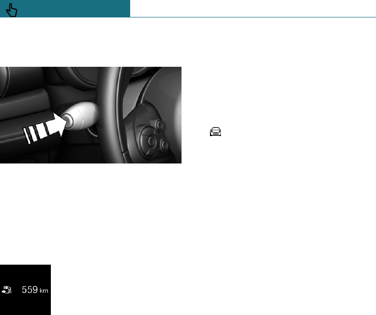
Calling up information on the
information display
Press the button on the turn indicator lever.
Information is displayed on the information
display in the instrument cluster.
Overview of the information
Info display
Repeated pressing of the but-
ton on the turn indicator lever
shows the following informa-
tion on the information dis-
play:
–Range.
–GREEN Info.
When GREEN mode is activated.
–Average consumption, fuel.
–Momentary consumption, fuel.
–Average speed.
–Date.
–Engine temperature display.
–Speed Limit Info.
–Speed.
The unit of dimension of some information
can be changed over.
Setting units of measurement, see page 42.
Selecting information
With the corresponding equipment, it is
possible to select which information from
the on-board computer can be called up on
the information display in the instrument
cluster.
Using the on-board monitor:
1. "My MINI"
2. "System settings"
3. "Displays"
4. "Instrument cluster"
5. Select the desired setting.
The setting is saved for the currently used
profile.
Detailed information
Range
Displays the estimated range available with
the remaining fuel.
The range is calculated based on your driv-
ing style over the last 30 km, 20 miles.
GREEN Info
The extension to the range achieved can be
displayed as bonus range.
Average fuel consumption
Calculated for the period during which the
engine is running.
The average consumption is calculated on
the route travelled since the on-board com-
puter was last reset.
Average speed
The calculation of average speed ignores
any stationary periods where the engine
was switched off manually.
Seite 136
CONTROLS Displays
136 Online Edition for Part no. 01402988211 - II/18
Draft
from BA-76
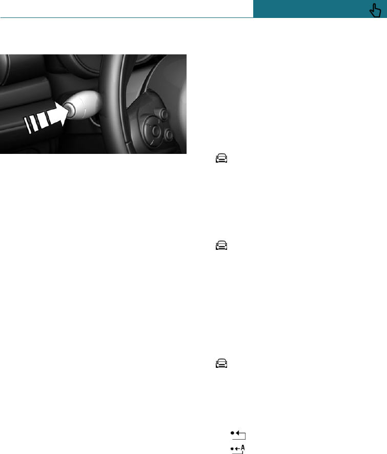
Resetting average values
Press and hold the button on the turn indi-
cator lever.
Engine temperature display
Displays current engine temperature from a
combination of coolant and engine oil tem-
perature. If the engine is at its optimum op-
erating temperature, the display is in the
centre position.
If the engine oil or coolant and therefore
the engine become too hot, a Check Control
message is displayed as well.
Checking the coolant level, see page 300.
Speed Limit Info
Speed Limit Info shows the currently detec-
ted speed limit in the instrument cluster.
On-board computer on the Control
Display
Principle
The on-board computer shows various vehi-
cle-related data, such as average values, on
the Control Display.
General
Two types of on-board computer are avail-
able on the Control Display:
–"On-board computer": average values
such as the fuel consumption are dis-
played. The values can be reset individu-
ally.
–"Trip computer": values provide an over-
view of a particular route, and can be re-
set as often as required.
Call up on-board computer or journey
computer
Using the on-board monitor:
1. "My MINI"
2. "Driving information"
3. "On-board computer" or "Trip computer"
Resetting the on-board computer
Using the on-board monitor:
1. "My MINI"
2. "Driving information"
3. "On-board computer"
4. "Consumption" or "Speed"
5. "OK"
Resetting the trip computer
Using the on-board monitor:
1. "My MINI"
2. "Driving information"
3. "Trip computer"
4. If necessary, tilt the Controller to the
left.
– "Reset": all values are reset.
– "Reset automatically": all values
are reset if the vehicle is at a stand-
still for approximately 4 hours.
5. If necessary, "OK"
Seite 137
Displays CONTROLS
137
Online Edition for Part no. 01402988211 - II/18
Draft
from BA-76

Driving Excitement
Principle
On the Control Display, sports instruments
can be shown and the vehicle status can be
checked before using the SPORT pro-
gramme.
Sports instruments
General
Values for performance and torque are
shown on the Control Display.
Show sports instruments
Using the on-board monitor:
1. "My MINI"
2. "Technology in action"
3. "Sport displays"
4. "Sports instruments"
Using MINI Driving Modes switch:
1. Activate SPORT.
2. "Sport displays"
3. "Sports instruments"
Speed warning
Principle
A speed limit can be set which triggers a
warning when it is reached.
General
The warning is repeated if the vehicle speed
exceeds the set speed limit again, after it
has dropped below 5 km/h/3 mph.
Displaying, setting or altering the
speed warning
Using the on-board monitor:
1. "My MINI"
2. "Vehicle settings"
3. "Speed warning"
4. "Warning at:"
5. Turn the Controller until the desired
speed is displayed.
6. Press the Controller.
Activating/deactivating the speed
warning
Using the on-board monitor:
1. "My MINI"
2. "Vehicle settings"
3. "Speed warning"
4. "Speed warning"
Setting the current speed as the
speed warning
Using the on-board monitor:
1. "My MINI"
2. "Vehicle settings"
3. "Speed warning"
4. "Select current speed"
LED ring on the central in-
strument
Principle
The LED ring changes its illumination in re-
sponse to certain functions.
Seite 138
CONTROLS Displays
138 Online Edition for Part no. 01402988211 - II/18
Draft
from BA-76
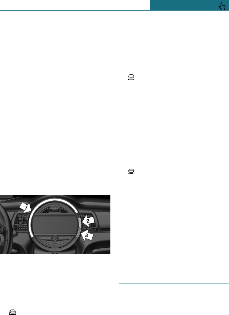
Basic displays
Basic functions that are usually displayed
permanently, for example the revolution
counter, can be set.
Event displays
Functions that are only displayed tempora-
rily can be set as event displays, for exam-
ple when the volume or temperature is ad-
justed.
Some assistance functions in the vehicle
can also be displayed on the LED ring. In
this case, the representation corresponds to
how the function appears on the particular
display.
An example: rev counter
The light animations of the basic rev coun-
ter display show the current engine speed
and the warning zone for the permitted en-
gine speed range, in the same way as the
rev counter in the instrument cluster.
Display
–Arrow 1: current engine speed.
–Arrow 2: advance warning zone.
–Arrow 3: warning zone.
Turn LED ring on/off
Using the on-board monitor:
1. "My MINI"
2. "System settings"
3. "Displays"
4. "Central display"
5. "Central display"
Setting the LED ring
Using the on-board monitor:
1. "My MINI"
2. "System settings"
3. "Displays"
4. "Central display"
5. "Standard view" or "Event view"
6. Select the desired setting.
To adjust the brightness
The brightness can be adjusted when night
lighting is active in the instrument cluster.
Using the on-board monitor:
1. "My MINI"
2. "System settings"
3. "Displays"
4. "Central display"
5. "Brightness at night"
6. Turn the Controller until the desired
brightness is obtained.
7. Press the Controller.
The setting is saved for the currently used
driver profile.
John Cooper Works: sport dis-
plays in the Head-Up Display
General
The sport displays in the Head-Up Display
primarily assist a dynamic driving style.
Seite 139
Displays CONTROLS
139
Online Edition for Part no. 01402988211 - II/18
Draft
from BA-76
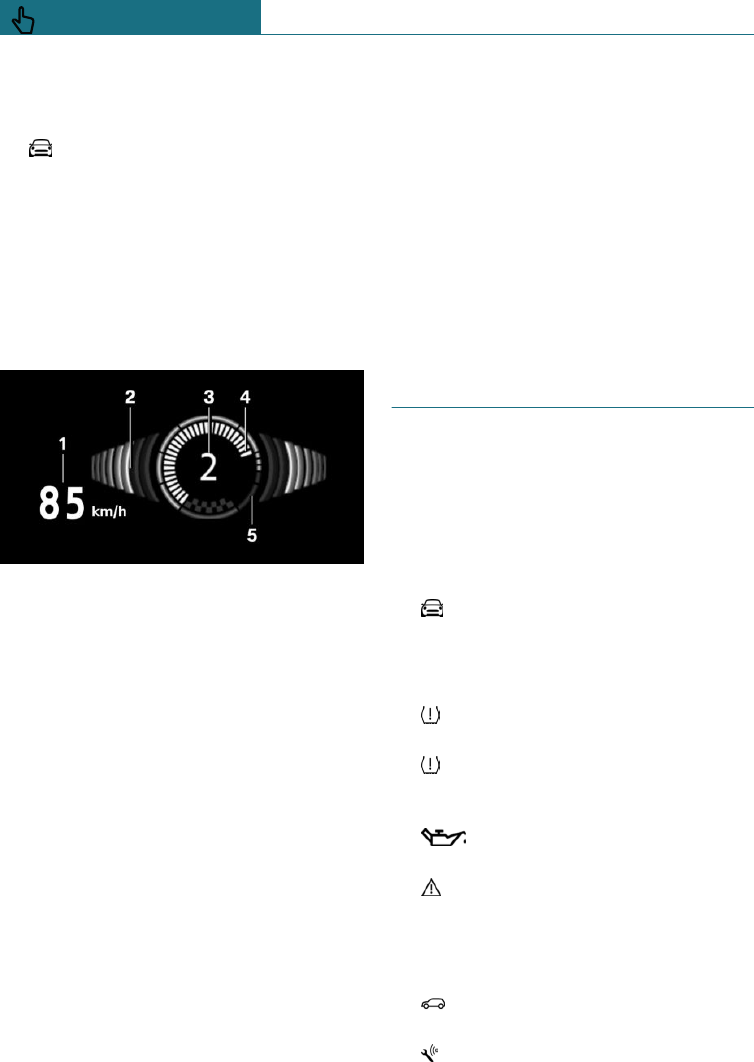
Switching on
Using the on-board monitor:
1. "My MINI"
2. "System settings"
3. "Displays"
4. "Head-up display"
5. "Information displayed"
6. "Sport displays"
Display
1Speed
2Shift Lights
3Gear display
4Current engine speed
5Warning zone, engine speed
Shift Lights
Principle
In the Head-Up Display, Shift Lights show
the optimum moment to shift. In this way,
the best possible vehicle acceleration is
achieved when adopting a dynamic driving
style.
Operating requirements
–Steptronic sport transmission:
Manual operation M/S and possibly Dy-
namic Traction Control DTC are activa-
ted.
–Fully depress the accelerator pedal.
Display
Grey fields illuminating successively indi-
cate when an gearshift is due.
As soon as the red fields illuminate, shift up
immediately.
When the maximum permissible engine
speed is reached, the entire display flashes
and the fuel supply is limited to protect the
engine.
Vehicle status
General
The status can be displayed or actions per-
formed for some systems.
Calling up the vehicle status
Using the on-board monitor:
1. "My MINI"
2. "Vehicle status"
Overview of the information
– "Flat Tyre Monitor": status of the
runflat indicator, see page 157.
– "Tyre Pressure Monitor": status of
the Tyre Pressure Monitor, see
page 152.
– "Engine oil level": electronic oil
level check, see page 296.
– "Check Control": Check Control mes-
sages are stored in the background and
can be shown on the Control Display.
Displaying of saved Check Control mes-
sages, see page 128.
– "Service requirements": display of
the service requirements, see page 131.
– "Teleservice Call": Teleservice Call.
Seite 140
CONTROLS Displays
140 Online Edition for Part no. 01402988211 - II/18
Draft
from BA-76
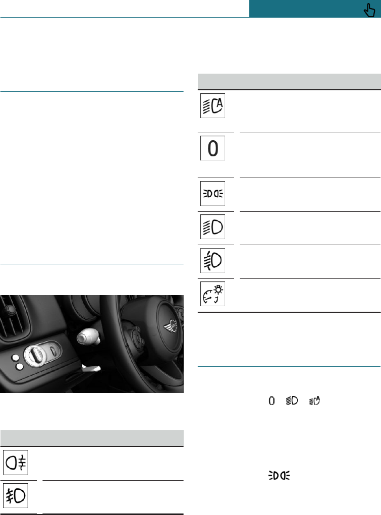
Lights
Vehicle equipment
This chapter describes all standard, country-
specific and special equipment available for
the model series. Therefore equipment
which is not installed in your vehicle, for
example on account of the optional equip-
ment selected or the country specification,
may also be described here. This also ap-
plies to safety-relevant functions and sys-
tems. Comply with the relevant laws and
regulations when using the corresponding
functions and systems.
Overview
Switch in the vehicle
The light switch element is located next to
the steering wheel.
Symbol Function
Rear fog lights.
Front fog lights.
Symbol Function
Automatic driving lights control.
Cornering light and variable
light distribution.
Lights off.
Automatic driving lights control.
Daytime driving lights.
Side lights.
Low-beam headlights.
Manual headlight beam throw
adjustment.
Instrument lighting.
Side lights, low-beam head-
lights and parking light
General
Switch position: , ,
If the driver's door is opened when the igni-
tion is switched off, the exterior lights are
switched off automatically.
Side lights
Switch position:
The vehicle is illuminated all round.
You should not leave the side lights on for
extended periods of time, since the vehicle
could discharge and you might not have
enough power to start the engine.
Seite 141
Lights CONTROLS
141
Online Edition for Part no. 01402988211 - II/18
Draft
from BA-76
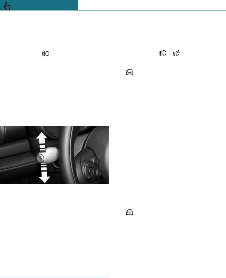
To park, switch on the one-sided parking
light, see page 142.
Low-beam headlights
Switch position:
The low-beam headlights illuminate when
the ignition is switched on.
Parking light
Principle
The vehicle can be illuminated on one side.
Switching on
With radio ready state switched off, push
the lever upwards or downwards beyond the
resistance point for approximately 2 sec-
onds.
Switching off
Press the lever briefly in the opposite direc-
tion as far as the resistance point.
Welcome lights and headlight
courtesy delay feature
Welcome lights
General
Depending on the equipment and the ambi-
ent brightness, individual light functions
may be switched on briefly when the vehi-
cle is unlocked.
Activating/deactivating
Switch position: ,
Using the on-board monitor:
1. "My MINI"
2. "Vehicle settings"
3. "Lights"
4. "Exterior lighting"
5. "Welcome lights"
The setting is saved for the currently used
driver profile.
Headlight courtesy delay feature
General
If the headlight flasher is activated after
switching off the radio ready state, the low-
beam headlights illuminate and remain on
for a certain amount of time.
Setting the duration
Using the on-board monitor:
1. "My MINI"
2. "Vehicle settings"
3. "Lights"
4. "Exterior lighting"
5. "Home lights"
6. Set the duration.
The setting is saved for the currently used
driver profile.
Seite 142
CONTROLS Lights
142 Online Edition for Part no. 01402988211 - II/18
Draft
from BA-76
Automatic driving lights con-
trol
Principle
Depending on ambient brightness, the sys-
tem switches the low-beam headlights on or
off automatically, for example in a tunnel, at
twilight and in rain or snow.
General
The headlights may also come on when the
sun is sitting low in a blue sky.
Activating
Switch position: ,
The indicator lamp in the instrument cluster
is illuminated when the low-beam head-
lights are switched on.
System limits
The automatic driving lights control is no
substitute for using your own judgement to
assess the light conditions.
The sensors are unable, for instance, to rec-
ognise fog or hazy weather. In such situa-
tions, switch on the lights manually to avoid
any safety risk.
Daytime driving lights
General
Switch position: ,
The daytime driving lights illuminate when
the ignition is switched on.
Activating/deactivating
In some countries daytime driving lights
are compulsory, in which case the daytime
driving lights cannot be deactivated.
Using the on-board monitor:
1. "My MINI"
2. "Vehicle settings"
3. "Lights"
4. "Exterior lighting"
5. Select the desired setting.
The setting is saved for the remote control
currently in use.
Cornering light and variable
light distribution
Cornering light
Switch position:
In sharp turns up to a specified speed, for
example in hairpin bends or when turning
off, a cornering light is added that illumi-
nates the inside area of the bend.
The cornering light is activated automati-
cally depending on the steering angle or use
of the turn indicators.
Variable light distribution
Principle
The variable light distribution enables even
better illumination of the carriageway.
General
The light distribution is automatically adap-
ted to the speed.
Activating
Switch position:
Variable light distribution is active when
the ignition is switched on.
Seite 143
Lights CONTROLS
143
Online Edition for Part no. 01402988211 - II/18
Draft
from BA-76
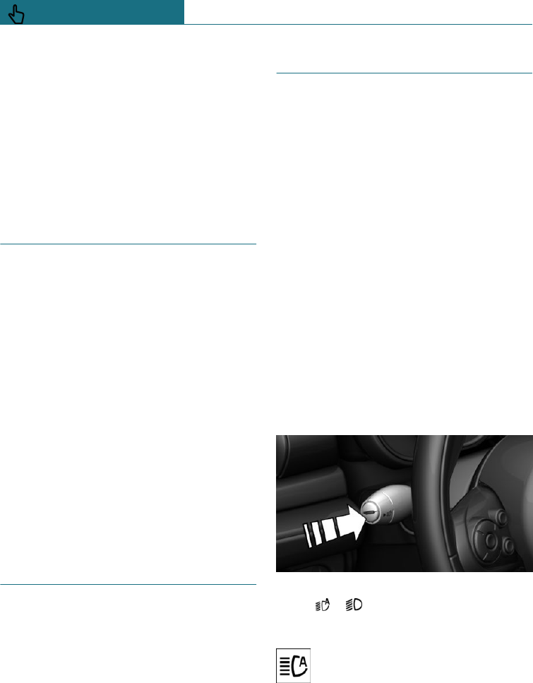
City light
The illuminated area of the low-beam head-
lights is extended on the sides.
Motorway beam pattern
The illumination width of the low-beam
headlights is expanded.
Manual headlight beam throw
adjustment
General
Depending on the equipment installed, ad-
just the beam throw of the low-beam head-
lights manually in accordance with the vehi-
cle load. Otherwise, the glare will disturb
drivers of oncoming vehicles.
Settings
Values after / are applicable when towing a
trailer.
–0/1 = 1 to 2 persons without luggage.
–1/1 = 5 persons without luggage.
–1/2 = 5 persons with luggage.
–2/2 = 1 person, boot fully loaded.
Adaptive headlight beam
throw adjustment
The adaptive headlight beam throw adjust-
ment compensates for acceleration and
braking manoeuvres to prevent oncoming
vehicles from being dazzled and to ensure
optimum illumination of the road.
High-beam assistance
Principle
High-beam assistance detects other road
users early on and activates or deactivates
the high beam depending on the traffic sit-
uation.
General
High-beam assistance ensures that the
high-beam headlights are switched on when
the traffic situation allows. The high-beam
headlights are not switched on by the sys-
tem in the low speed range.
The system responds to light from oncom-
ing traffic and traffic driving ahead of you,
and to ambient lighting, for example in
built-up areas.
The high-beam headlights can be switched
on and off manually at any time.
Activating/deactivating
Switch position, depending on the equip-
ment: ,
Press the button on the turn indicator lever.
The indicator lamp in the instrument
cluster is illuminated when the low-
beam headlights are switched on.
The system will switch automatically be-
tween low-beam and high-beam headlights.
Seite 144
CONTROLS Lights
144 Online Edition for Part no. 01402988211 - II/18
Draft
from BA-76
The blue indicator lamp in the in-
strument cluster illuminates if the
high beam is switched on by the sys-
tem.
High-beam assistance is deactivated by
switching the high beams on and off man-
ually, see page 110.
To reactivate high-beam assistance, press
the button on the turn indicator lever.
System limits
High-beam assistance cannot replace the
driver's own judgement as to when to use
the high-beam headlights. Therefore acti-
vate the dipped headlights manually if the
situation requires it.
In the following situations, the system will
not operate or its operation will be impaired
and your intervention may be required:
–In extremely unfavourable weather con-
ditions such as fog or heavy precipita-
tion.
–When detecting poorly-lit road users
such as pedestrians, cyclists or horse-
back riders or carts, and when trains or
ships are close to the road, or when ani-
mals are crossing the road.
–On narrow bends, on steep hilltops or in
depressions, when there is crossing traf-
fic or if the view of oncoming vehicles
on a motorway is obstructed.
–In poorly-lit towns or where there are
high reflective signs.
–When the windscreen in front of the
rearview mirror is covered with conden-
sation, dirt, stickers, labels, etc.
Fog lights
Front fog lights
Principle
The fog lights work alongside the low-beam
headlights to illuminate a wider area of the
roadway.
Operating requirements
Before the fog lights are switched on, the
side lights or low-beam headlights must be
switched on.
Switching on/off
Press the button.
The green indicator lamp illumi-
nates if the fog lights are switched on.
If automatic driving lights control, see
page 143, has been activated, the low-beam
headlights illuminate automatically when
the front fog lights are switched on.
Rear fog lights
Operating requirements
Before the rear fog lights are switched on,
the low-beam headlights or the fog lights
must be switched on.
Switching on/off
Press the button.
The yellow indicator lamp illumi-
nates if the rear fog lights are switched on.
If automatic driving lights control, see
page 143, has been activated, the low-beam
headlights switch on automatically when
the rear fog lights are switched on.
Seite 145
Lights CONTROLS
145
Online Edition for Part no. 01402988211 - II/18
Draft
from BA-76
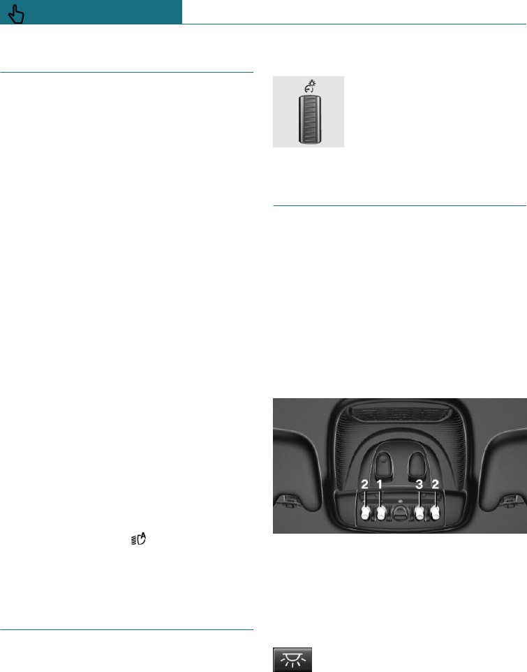
Left-hand/right-hand traffic
General
When driving in countries where vehicles
drive on the opposite side of the road to
your vehicle's country of registration, you
will need to prevent your headlights from
dazzling oncoming vehicles.
Halogen headlights
Light distribution of the headlights pre-
vents the dipped-beam headlights from daz-
zling other road users even when driving in
a country where vehicles drive on the other
side of the road to your vehicle's country of
registration.
LED headlights
Light distribution of the headlights pre-
vents the dipped-beam headlights from daz-
zling other road users even when driving in
a country where vehicles drive on the other
side of the road to your vehicle's country of
registration.
Variable light distribution
When driving in countries which drive on
the other side of the road to your vehicle's
country of registration, do not drive with
the switch in position . Otherwise, the
variable light distribution may result in a
blinding effect.
Instrument lighting
Operating requirements
The brightness can only be adjusted when
the side lights or the low-beam headlights
are switched on.
To adjust
The brightness can be set us-
ing the knurled wheel.
Interior light
General
Depending on equipment, the interior light,
the footwell lights, door entry lighting and
the courtesy lighting are controlled auto-
matically.
The brightness of some equipment is con-
trolled by the knurled wheel for the instru-
ment lighting.
Overview
1Interior light
2Reading lights
3Ambient lighting
Switching the interior light on/off
Press the button.
To switch off permanently: press and hold
the button for approximately 3 seconds.
Seite 146
CONTROLS Lights
146 Online Edition for Part no. 01402988211 - II/18
Draft
from BA-76
Switching the reading lights on/off
manually
Press the button.
The reading lights are located in the front
beside the interior light.
Ambient lighting
General
Depending on the equipment, the lighting
for some of the interior lights can be set.
Changing colour
Press switch forwards or back: man-
ual colour change.
Press the switch forwards or back-
wards and hold for approximately
3 seconds, until the ambient light il-
luminates several times: automatic colour
change. Press the button again to end the
colour change.
To adjust the brightness
Depending on equipment, the brightness of
the ambient light can be set using the
knurled wheel for the instrument lighting or
on the Control Display.
Using the on-board monitor:
1. "My MINI"
2. "Vehicle settings"
3. "Lights"
4. "Interior lighting"
5. "Brightness"
6. To adjust the brightness.
Seite 147
Lights CONTROLS
147
Online Edition for Part no. 01402988211 - II/18
Draft
from BA-76
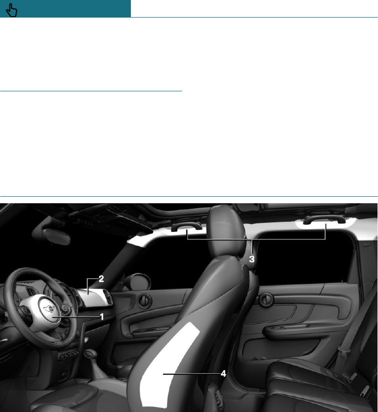
Safety
Vehicle equipment
This chapter describes all standard, country-
specific and special equipment available for
the model series. Therefore equipment
which is not installed in your vehicle, for
example on account of the optional equip-
ment selected or the country specification,
may also be described here. This also ap-
plies to safety-relevant functions and sys-
tems. Comply with the relevant laws and
regulations when using the corresponding
functions and systems.
Airbags
1Front airbag, driver
2Front airbag, front passenger
3Head airbag
4Side airbag
Front airbags
Front airbags protect the driver and front
passenger in the event of a head-on colli-
sion where the protection of the seat belts
alone would no longer be sufficient.
Side airbag
In a side-on crash, the side airbag supports
the body at the side in the chest and pelvic
area.
Seite 148
CONTROLS Safety
148 Online Edition for Part no. 01402988211 - II/18
Draft
from BA-76
Head airbag
The head airbag supports the head in the
event of a side-on crash.
Protective effect
Airbags are not activated in every collision,
for example in minor accidents and rear-end
collisions.
Notes on achieving optimum airbag
effectiveness
WARNING
If the seat position is wrong or the deploy-
ment area of the airbag is restricted, the
airbag system cannot provide the intended
protection, or may cause additional inju-
ries when it deploys. There is a danger of
injury or even death. Observe the
following to achieve optimum protective
effect.
–Keep your distance from the airbags.
–Always grip the steering wheel on the
steering wheel rim. Place your hands in
the 3 o'clock and 9 o'clock positions to
minimise the risk of injury to hands or
arms when the airbag deploys.
–Make sure that the front-seat passenger
is sitting correctly, in other words with
feet or legs in the footwell, not resting
them on the dashboard.
–Make sure that vehicle occupants keep
their head away from the side airbag.
–Do not position any other persons, ani-
mals or objects between the airbags and
persons.
–Keep the dashboard and windscreen in
the area of the passenger's side free, for
example do not attach adhesive foil or
covers and do not fit brackets for navi-
gation devices or mobile telephones.
–Do not attach anything to the airbag
covers with adhesive; never cover them
or modify them in any way.
–Do not use the front airbag cover on the
front passenger's side as a tray.
–Covers, seat covers, cushions or other
objects not specifically suitable for seats
with integral side airbags must not be
fitted to the front seats.
–Seat covers, cushions or other objects
not specifically suitable for seats with
integral side airbags must not be fitted
to the front seats.
–Do not hang items of clothing such as
coats or jackets over the backrests.
–Do not modify individual components of
the system or its wiring in any way. This
also applies to the covers of the steering
wheel, the dashboard and seats.
–Do not dismantle the airbag system.
Even if all these notes are complied with,
depending on the circumstances in which
an accident occurs, certain injuries as a re-
sult of contact with the airbag cannot be en-
tirely ruled out.
The noise caused by the deployment of an
airbag may lead to temporary hearing loss
for vehicle occupants sensitive to noise.
Operational readiness of the airbag
system
Safety notes
WARNING
Individual components of the airbag sys-
tem can be hot after airbag deployment.
There is a danger of injury. Do not touch
individual components.
Seite 149
Safety CONTROLS
149
Online Edition for Part no. 01402988211 - II/18
Draft
from BA-76
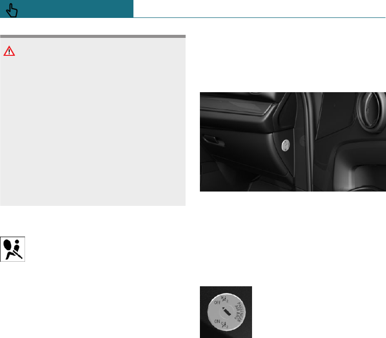
WARNING
Work carried out incorrectly can lead to a
failure, a malfunction or accidental deploy-
ment of the airbag system. If there is a
malfunction, the airbag system might not
deploy as intended in an accident, in spite
of the accident being of the appropriate
severity. There is a danger of injury or
even death. Have the airbag system tested,
repaired or removed and disposed of by a
Service Partner of the manufacturer or an-
other qualified Service Partner or a spe-
cialist workshop.
Correct function
When the ignition is switched on,
the warning lamp in the instrument
cluster briefly illuminates in order to
show the operational readiness of the entire
airbag system and the belt tensioner.
Airbag system malfunction
–The warning lamp does not illuminate
after the ignition is switched on.
–The warning lamp is permanently illumi-
nated.
Not for Australia/New Zealand: Key
switch for front passenger airbags
General
The front and side airbags for the front pas-
senger can be deactivated and reactivated
using the integrated key from the remote
control.
Deactivating the front passenger
airbags
1. Insert the key and press inwards where
necessary.
2. While the key is pressed inwards, turn it
to the OFF position as far as it will go.
Once the stop position has been
reached, remove the key.
3. Make sure that the key switch is in the
end position so that the airbags are de-
activated.
The front passenger airbags are deactivated.
The driver's airbags remain active.
If a child restraint system is no longer fitted
in the front passenger seat, reactivate the
front passenger airbags so that they are
triggered as intended in the event of an ac-
cident.
Seite 150
CONTROLS Safety
150 Online Edition for Part no. 01402988211 - II/18
Draft
from BA-76
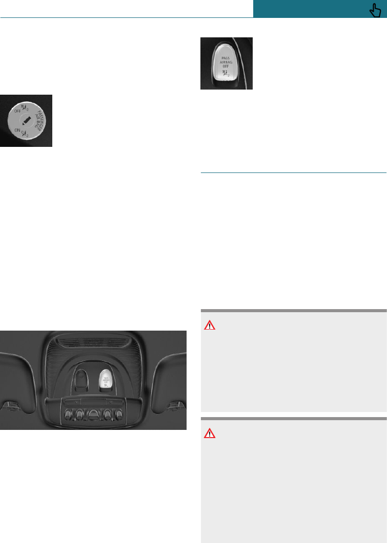
The airbag condition is displayed on the
front passenger airbag indicator lamp, see
page 151.
Activating the front passenger airbags
1. Insert the key and press inwards where
necessary.
2. While the key is pressed inwards, turn it
to the ON position as far as it will go.
Once the stop position has been
reached, remove the key.
3. Make sure that the key switch is in the
end position so that the airbags are acti-
vated.
The front passenger airbags are reactivated
and can deploy correctly if the need arises.
Indicator lamp for front passenger
airbags
The indicator lamp for the front passenger
airbags shows the operating status of the
front passenger airbags.
After switching on the ignition, the light il-
luminates briefly and then shows whether
the airbags are activated or deactivated.
–When front passenger air-
bags are deactivated, the
indicator lamp remains il-
luminated.
–When front passenger air-
bags are activated, the in-
dicator lamp is not illumi-
nated.
Active pedestrian protection
Principle
The active pedestrian protection system rai-
ses the bonnet if the vehicle's front end col-
lides with a pedestrian. Sensors underneath
the bumper are used for detection. This pro-
vides additional deformation space under-
neath the active bonnet for the subsequent
head impact.
Safety notes
WARNING
The system can trigger inadvertently if
contact is made with individual compo-
nents of the hinges and bonnet locks.
There is a danger of injury or damage to
property. Do not touch individual compo-
nents of the hinges and bonnet locks.
WARNING
Changes to the pedestrian protection sys-
tem can lead to a failure, a malfunction or
accidental triggering of the pedestrian
protection system. There is a danger of in-
jury or even death. Do not modify individ-
ual components of the pedestrian protec-
tion system or its wiring in any way. Do
not dismantle the system.
Seite 151
Safety CONTROLS
151
Online Edition for Part no. 01402988211 - II/18
Draft
from BA-76
WARNING
Work carried out incorrectly can lead to a
failure, a malfunction or accidental trig-
gering of the system. If there is a malfunc-
tion, the system might not trigger as in-
tended in an accident, in spite of the
accident being of the appropriate severity.
There is a danger of injury or even death.
Have the system tested, repaired or re-
moved and disposed of by a Service Part-
ner of the manufacturer or another quali-
fied Service Partner or a specialist
workshop.
System limits
The active pedestrian protection system is
only triggered at speeds between approxi-
mately 30 km/h, approximately 18 mph and
55 km/h, approximately 34 mph.
For safety reasons, the system may also
trigger in rare instances where impact with
a pedestrian cannot be excluded beyond all
doubt, for example:
–Collision with a skip or a boundary post.
–Collision with animals.
–Stone impact.
–Driving into a snow drift.
Triggered pedestrian protection
WARNING
If the system has triggered or is damaged,
its functions will be restricted, or will no
longer work at all. There is a danger of in-
jury or even death.
If the system has triggered or is damaged,
have it checked and renewed at a Service
Partner of the manufacturer or another
qualified Service Partner or a specialist
workshop.
NOTE
Opening the bonnet when the pedestrian
protection system has triggered can result
in damage to the bonnet or the pedestrian
protection. There is a danger of damage to
property. Do not open the bonnet after the
Check Control message is displayed. Have
a check performed by a Service Partner of
the manufacturer or another qualified
Service Partner or a specialist workshop.
Malfunction
A Check Control message is shown.
The system has been triggered or is
faulty.
Immediately drive at moderate speed to a
Service Partner of the manufacturer or an-
other qualified Service Partner or a special-
ist workshop to have the system checked
and repaired.
Tyre Pressure Monitor TPM
Principle
The system monitors the tyre inflation pres-
sure in the four fitted tyres. The system
warns if the tyre inflation pressure in one or
more tyres has fallen considerably.
General
Sensors in the tyre valves measure the tyre
inflation pressure and, depending on the
model, the tyre temperature.
To operate the system, also follow the other
information and notes under Tyre inflation
pressure, see page 276.
Seite 152
CONTROLS Safety
152 Online Edition for Part no. 01402988211 - II/18
Draft
from BA-76
Operating requirements
The following requirements must be met for
the system, otherwise reliable signalling of
a loss of tyre inflation pressure is not en-
sured:
–After every tyre or wheel change, a re-
set must be carried out with the correct
tyre inflation pressure.
–A reset must be carried out after the
tyre inflation pressure has been adjus-
ted to a new value.
–Wheels with TPM wheel electronics.
Status display
Current status
The status of the system, for example
whether the system is active, can be shown
on the Control Display.
Using the on-board monitor:
1. "My MINI"
2. "Vehicle status"
3. "Tyre Pressure Monitor"
The current status is displayed.
Additional information
The current tyre inflation pressures are
shown too. The values shown are current
values and may change due to the effects of
driving conditions or weather conditions.
Performing a reset
Using the on-board monitor:
1. "My MINI"
2. "Vehicle status"
3. "Tyre Pressure Monitor"
4. Start the engine but do not drive off.
5. Reset the tyre inflation pressure with
"Perform reset".
6. Drive off.
The following is displayed: "Resetting Tyre
Pressure Monitor…".
After driving for a short time over 30 km/h,
19 mph the set tyre pressures are accepted
as target values. The reset is completed au-
tomatically during the journey.
After a successfully completed reset, the
following is displayed: "Tyre Pressure
Monitor active. See label for recommended
pressures.".
You can interrupt your journey at any time.
The reset resumes automatically when you
continue your journey.
Messages
General
Dynamic Stability Control DSC will be acti-
vated if necessary as soon as a message for
low tyre inflation pressure appears.
Safety notes
WARNING
A damaged normal tyre with too little or
no tyre inflation pressure impairs driving
properties, for example steering and brak-
ing. Tyres with run-flat properties allow a
limited level of stability to be maintained.
There is a danger of accidents. Do not con-
tinue driving if the vehicle is fitted with
normal tyres. Comply with the notes on
run-flat tyres and continuing to drive with
these tyres.
Seite 153
Safety CONTROLS
153
Online Edition for Part no. 01402988211 - II/18
Draft
from BA-76
If a tyre inflation pressure test is
required
Message
A symbol with a Check Control message is
shown on the Control Display.
Symbol Possible cause
The system has detected a
wheel change, but no reset has
been run.
No reset has been performed on
the system. The system uses the
tyre inflation pressures saved
during the last reset for the
warning.
The tyre was not inflated prop-
erly.
The tyre inflation pressure has
dropped compared to the last re-
set.
Measure
1. Check the tyre inflation pressure and ad-
just as necessary.
2. Perform a reset of the system.
If the tyre inflation pressure is
insufficient
Message
A yellow warning lamp is illuminated
in the instrument cluster.
In addition, a symbol with a Check Control
message is shown on the Control Display.
Symbol Possible cause
There has been a loss of tyre in-
flation pressure.
No reset has been performed on
the system. The system uses the
tyre inflation pressures saved
during the last reset for the
warning.
Measure
1. Reduce speed and continue driving at
moderate speed. Do not exceed a speed
of 130 km/h, 80 mph.
2. At the next opportunity, for example fill-
ing station, check the tyre inflation
pressure in all four tyres and correct if
necessary.
3. Perform a reset of the system.
If there is a significant loss of tyre
inflation pressure
Message
A yellow warning lamp is illuminated
in the instrument cluster.
In addition, a symbol with the affected tyre
is shown in a Check Control message on the
Control Display.
Symbol Possible cause
There is a flat tyre or substantial
loss of tyre inflation pressure.
No reset has been performed on
the system. The system uses the
tyre inflation pressures saved
during the last reset for the
warning.
Seite 154
CONTROLS Safety
154 Online Edition for Part no. 01402988211 - II/18
Draft
from BA-76
Measure
1. Reduce your speed and carefully stop
the vehicle. Avoid violent or sudden
braking and steering manoeuvres.
2. Check whether the vehicle is equipped
with standard tyres or run-flat tyres.
The symbol identifying run-flat tyres,
see page 280, is a circle with the letters
RSC on the tyre side wall.
What to do in the event of a flat
tyre
Standard tyres
1. Identify the damaged tyre.
To do this, check the tyre inflation pres-
sure in all four tyres, for example using
the tyre pressure indicator of a flat tyre
kit.
If all four tyres are inflated to the cor-
rect tyre inflation pressures, the Tyre
Pressure Monitor might not have been
reset. Perform a reset.
If all four tyres are inflated to the cor-
rect tyre inflation pressures, the runflat
indicator might not have been initial-
ised. In this case initialise the system.
If it is not possible to identify tyre dam-
age, contact a Service Partner of the
manufacturer or another qualified Serv-
ice Partner or a specialist workshop.
2. Repair the flat tyre, for example using a
flat tyre kit or by changing the wheel.
The use of sealant, for example a flat tyre
kit, can damage the TPM wheel electronics.
In this case, have the electronics replaced at
the next opportunity.
Run-flat tyres
Safety notes
WARNING
A run-flat tyre which has low tyre inflation
pressure or no tyre inflation pressure at all
will change the vehicle's handling charac-
teristics, for example there may be re-
duced directional stability when braking,
longer braking distances and different
self-steering characteristics. There is a
danger of accidents.
Drive with care and do not exceed a speed
of 80 km/h, 50 mph.
WARNING
Continuing to drive with a flat tyre can re-
sult in heavy trailers starting to slalom.
There is a danger of accidents or damage
to property. When driving with a trailer
and a flat tyre, do not exceed the speed of
60 km/h, approximately 35 mph. In case of
swaying or fishtailing motions, brake im-
mediately and make the necessary steer-
ing corrections as carefully as possible.
Maximum speed
If a tyre is damaged you can continue your
journey, but do not exceed a maximum
speed of 80 km/h, 50 mph.
Continuing a journey with a flat tyre
If you continue a journey with a flat tyre:
1. Avoid violent or sudden braking and
steering manoeuvres.
2. Do not exceed a speed of 80 km/h,
50 mph.
3. As soon as there is an opportunity,
check the tyre inflation pressure in all
four tyres.
Seite 155
Safety CONTROLS
155
Online Edition for Part no. 01402988211 - II/18
Draft
from BA-76
If all four tyres are inflated to the cor-
rect tyre inflation pressures, the Tyre
Pressure Monitor might not have been
reset. Perform a reset.
Possible driving distance with a deflated
tyre
The possible driving distance varies de-
pending on the load and stresses the vehicle
is subjected to, for example speed, road
properties, outside temperature. The driving
distance can be shorter or, if the driving
style is more careful, longer.
If the vehicle is moderately loaded and used
under favourable conditions, it is possible
to travel up to 80 km, 50 miles.
Driving properties with damaged tyres
On a journey with damaged tyres, handling
characteristics change and may result in the
following situations, for example:
–The vehicle losing traction more quickly.
–Longer braking distances.
–Changed self-steering characteristics.
Adapt your driving style. Avoid abrupt
steering or driving over obstacles, for exam-
ple kerbs or potholes.
Final tyre failure
Vibration or loud noises during the journey
may be an indication that the tyre has fi-
nally failed.
Reduce your speed and stop the vehicle.
Parts of the tyre could detach, which could
lead to an accident.
Do not continue driving, but contact a Serv-
ice Partner of the manufacturer or another
qualified Service Partner or a specialist
workshop.
System limits
Temperature
The tyre inflation pressure depends on the
temperature of the tyre.
The tyre inflation pressure increases as the
tyre temperature increases, for example
during driving or due to exposure to sun-
light.
Tyre inflation pressure decreases if the tyre
temperature drops.
Through this behaviour, a warning may be
triggered if there are major temperature
drops, due to the given warning limits.
Sudden loss of tyre inflation pressure
No warning can be given by the system of
extreme, sudden tyre failure caused by ex-
ternal factors.
Reset not carried out
The system will not function correctly if a
reset has not been carried out, for example,
a flat tyre is reported in spite of the correct
tyre pressure.
Malfunction
The yellow warning lamp flashes and
is then illuminated continuously. A
Check Control message is shown.
Tyre pressure losses cannot be detected.
In these cases:
–A wheel without TPM wheel electronics
is fitted, for example emergency wheel:
have the wheels checked if necessary.
–Malfunction: have the system checked.
–The system was unable to complete the
reset. Perform a system reset again.
–Fault due to systems or devices with the
same radio frequency: the system is au-
tomatically reactivated upon leaving the
field of interference.
Seite 156
CONTROLS Safety
156 Online Edition for Part no. 01402988211 - II/18
Draft
from BA-76
Runflat indicator RPA
Principle
The system identifies a loss of tyre inflation
pressure by comparing the rotational speeds
of the individual wheels during the journey.
If a tyre loses inflation pressure, its diame-
ter changes. This in turn alters the rota-
tional speed of the corresponding wheel.
The difference will be detected and reported
as a flat tyre.
The system does not measure the tyre infla-
tion pressure as such.
Operating requirements
The following requirements must be met for
the system, otherwise reliable signalling of
a loss of tyre inflation pressure is not en-
sured:
–After every tyre or wheel change, an ini-
tialisation must be carried out with the
correct tyre inflation pressure.
–An initialisation must be carried out af-
ter the tyre inflation pressure has been
adjusted to a new value.
Status display
It is possible to display the current status of
the runflat indicator, for example to check
whether the RPA is active.
Using the on-board monitor:
1. "My MINI"
2. "Vehicle status"
3. "Flat Tyre Monitor"
The status is displayed.
Initialisation required
An initialisation must be performed in the
following situations:
–After adjusting the tyre inflation pres-
sure.
–After a tyre or wheel change.
Performing an initialisation
On initialisation, the current tyre pressures
are saved as a reference for detection of a
flat tyre. The initialisation is started by con-
firming the correct tyre inflation pressures.
When driving with snow chains fitted, do
not initialise the system.
Using the on-board monitor:
1. "My MINI"
2. "Vehicle status"
3. "Flat Tyre Monitor"
4. Start the engine but do not drive off.
5. Start the initialisation: "Perform reset".
6. Drive off.
Initialising is completed during the journey;
this process can be interrupted at any time.
Initialising resumes automatically when you
continue your journey.
Messages
General
Dynamic Stability Control DSC is activated
if necessary as soon as the message for a
flat tyre appears.
Safety note
WARNING
A damaged normal tyre with too little or
no tyre inflation pressure impairs driving
properties, for example steering and brak-
ing. Tyres with run-flat properties allow a
limited level of stability to be maintained.
There is a danger of accidents. Do not con-
tinue driving if the vehicle is fitted with
Seite 157
Safety CONTROLS
157
Online Edition for Part no. 01402988211 - II/18
Draft
from BA-76
normal tyres. Comply with the notes on
run-flat tyres and continuing to drive with
these tyres.
Flat tyre message
A yellow warning lamp is illuminated
in the instrument cluster.
In addition, a symbol with a Check Control
message is shown on the Control Display.
Symbol Possible cause
There is a flat tyre or substantial
loss of tyre inflation pressure.
Measure
1. Reduce your speed and carefully stop
the vehicle. Avoid violent or sudden
braking and steering manoeuvres.
2. Check whether the vehicle is equipped
with standard tyres or run-flat tyres.
The symbol identifying run-flat tyres,
see page 280, is a circle with the letters
RSC on the tyre side wall.
What to do in the event of a flat
tyre
Standard tyres
1. Identify the damaged tyre.
To do this, check the tyre inflation pres-
sure in all four tyres, for example using
the tyre pressure indicator of a flat tyre
kit.
If all four tyres are inflated to the cor-
rect tyre inflation pressures, the Tyre
Pressure Monitor might not have been
reset. Perform a reset.
If all four tyres are inflated to the cor-
rect tyre inflation pressures, the runflat
indicator might not have been initial-
ised. In this case initialise the system.
If it is not possible to identify tyre dam-
age, contact a Service Partner of the
manufacturer or another qualified Serv-
ice Partner or a specialist workshop.
2. Repair the flat tyre, for example using a
flat tyre kit or by changing the wheel.
The use of sealant, for example a flat tyre
kit, can damage the TPM wheel electronics.
In this case, have the electronics replaced at
the next opportunity.
Run-flat tyres
Safety notes
WARNING
A run-flat tyre which has low tyre inflation
pressure or no tyre inflation pressure at all
will change the vehicle's handling charac-
teristics, for example there may be re-
duced directional stability when braking,
longer braking distances and different
self-steering characteristics. There is a
danger of accidents.
Drive with care and do not exceed a speed
of 80 km/h, 50 mph.
WARNING
Continuing to drive with a flat tyre can re-
sult in heavy trailers starting to slalom.
There is a danger of accidents or damage
to property. When driving with a trailer
and a flat tyre, do not exceed the speed of
60 km/h, approximately 35 mph. In case of
swaying or fishtailing motions, brake im-
mediately and make the necessary steer-
ing corrections as carefully as possible.
Seite 158
CONTROLS Safety
158 Online Edition for Part no. 01402988211 - II/18
Draft
from BA-76

Maximum speed
If a tyre is damaged you can continue your
journey, but do not exceed a maximum
speed of 80 km/h, 50 mph.
Continuing a journey with a flat tyre
If you continue a journey with a flat tyre:
1. Avoid violent or sudden braking and
steering manoeuvres.
2. Do not exceed a speed of 80 km/h,
50 mph.
3. As soon as there is an opportunity,
check the tyre inflation pressure in all
four tyres.
If all four tyres are inflated to the cor-
rect tyre inflation pressures, the runflat
indicator might not have been initial-
ised. In this case initialise the system.
Possible driving distance with a deflated
tyre
The possible driving distance varies de-
pending on the load and stresses the vehicle
is subjected to, for example speed, road
properties, outside temperature. The driving
distance can be shorter or, if the driving
style is more careful, longer.
If the vehicle is moderately loaded and used
under favourable conditions, it is possible
to travel up to 80 km, 50 miles.
Driving properties with damaged tyres
On a journey with damaged tyres, handling
characteristics change and may result in the
following situations, for example:
–The vehicle losing traction more quickly.
–Longer braking distances.
–Changed self-steering characteristics.
Adapt your driving style. Avoid abrupt
steering or driving over obstacles, for exam-
ple kerbs or potholes.
Final tyre failure
Vibration or loud noises during the journey
may be an indication that the tyre has fi-
nally failed.
Reduce your speed and stop the vehicle.
Parts of the tyre could detach, which could
lead to an accident.
Do not continue driving, but contact a Serv-
ice Partner of the manufacturer or another
qualified Service Partner or a specialist
workshop.
System limits
In the following situations, the system
could be slow to respond or operate incor-
rectly:
–A natural, even loss of tyre inflation
pressure in all four tyres that occurs
over time is not detected. Consequently,
check the tyre inflation pressure at reg-
ular intervals.
–No warning can be given in the event of
sudden tyre failure caused by external
factors.
–If the system has not been initialised.
–When driving on snow-covered or slip-
pery surfaces.
–Dynamic driving style: drive wheels slip-
ping, high lateral acceleration.
–Driving with snow chains.
Intelligent Safety
Principle
Intelligent Safety enables Driver Assistance
Systems to be operated centrally.
The Intelligent Safety Systems can help to
avoid a collision that would otherwise oc-
cur.
Seite 159
Safety CONTROLS
159
Online Edition for Part no. 01402988211 - II/18
Draft
from BA-76
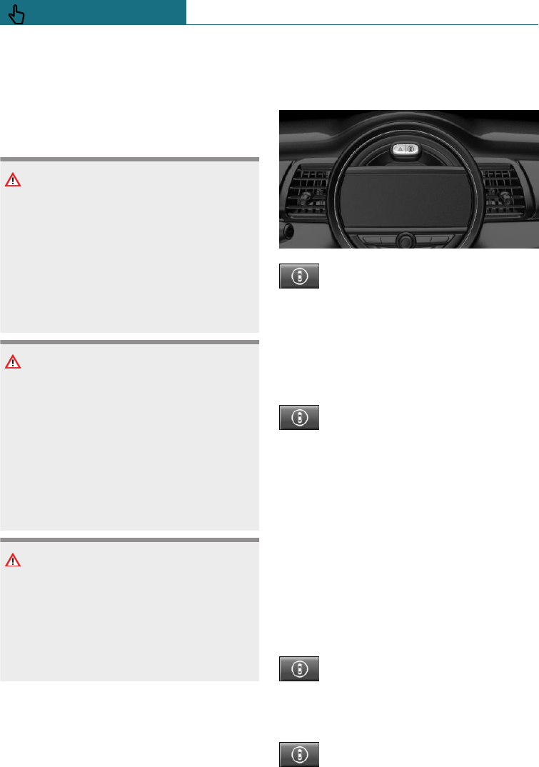
–Front-end collision with light braking
function, see page 161.
–Person warning with City light braking
function, see page 164.
Safety notes
WARNING
The system does not relieve you of your
personal responsibility to assess the visi-
bility conditions and traffic situation cor-
rectly. There is a danger of accidents.
Adapt your driving style to the traffic con-
ditions. Observe the traffic situation and
intervene actively if the situation warrants
it.
WARNING
Displays and warnings do not relieve you
of personal responsibility. System limita-
tions can mean that warnings or system
responses are not issued or are issued too
late, incorrectly, or without justification.
There is a danger of accidents. Adapt your
driving style to the traffic conditions. Ob-
serve the traffic situation and intervene
actively if the situation warrants it.
WARNING
Due to system limitations, individual func-
tions may not work properly when tow
starting/towing with activated Intelligent
Safety Systems. There is a danger of acci-
dents. Switch off all Intelligent Safety Sys-
tems before tow-starting/towing.
Overview
Button in the vehicle
Intelligent Safety button
Switching on/off
Several Intelligent Safety Systems are active
automatically at the start of each journey.
Several Intelligent Safety Systems are active
depending on the last setting.
Press the button briefly:
–The menu for the Intelligent
Safety Systems is shown. The
systems are switched off indi-
vidually depending on the indi-
vidual setting.
–LED illuminates orange or is extin-
guished, depending on individual set-
ting.
Press the button twice if necessary to
switch off the Lane Departure Warning.
Settings can be performed. The individual
settings are saved for the currently used
driver profile.
Press the button again:
–All Intelligent Safety Systems
are switched on.
–The LED is illuminated green.
Press and hold down the button:
Seite 160
CONTROLS Safety
160 Online Edition for Part no. 01402988211 - II/18
Draft
from BA-76
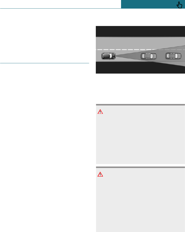
–All Intelligent Safety Systems are
switched off.
–The LED is extinguished.
Front-end collision with light
braking function
Principle
The system can help avoid accidents. If an
accident cannot be avoided, the system
helps to reduce the collision speed.
The system warns of the possible risk of
collision and brakes automatically, as neces-
sary.
The automatic braking intervention is done
with limited force and duration.
The system is controlled by a camera at the
base of the rearview mirror.
The front-end collision warning is also
available if the Cruise Control is disabled.
When deliberately approaching a vehicle,
the front-end collision warning and braking
intervention are activated later to avoid un-
justified system responses.
General
From speeds of approximately 5 km/h, ap-
proximately 3 mph, the system provides a
two-stage warning any possible risk of colli-
sion with vehicles. The timing of these
warnings may vary depending on the cur-
rent driving situation.
Braking intervention is permitted up to a
speed of approximately 80 km/h, approxi-
mately 50 mph.
Detection range
Objects detected by the system are taken
into account.
Safety notes
WARNING
The system does not relieve you of your
personal responsibility to assess the visi-
bility conditions and traffic situation cor-
rectly. There is a danger of accidents.
Adapt your driving style to the traffic con-
ditions. Observe the traffic situation and
intervene actively if the situation warrants
it.
WARNING
Displays and warnings do not relieve you
of personal responsibility. System limita-
tions can mean that warnings or system
responses are not issued or are issued too
late, incorrectly, or without justification.
There is a danger of accidents. Adapt your
driving style to the traffic conditions. Ob-
serve the traffic situation and intervene
actively if the situation warrants it.
Seite 161
Safety CONTROLS
161
Online Edition for Part no. 01402988211 - II/18
Draft
from BA-76
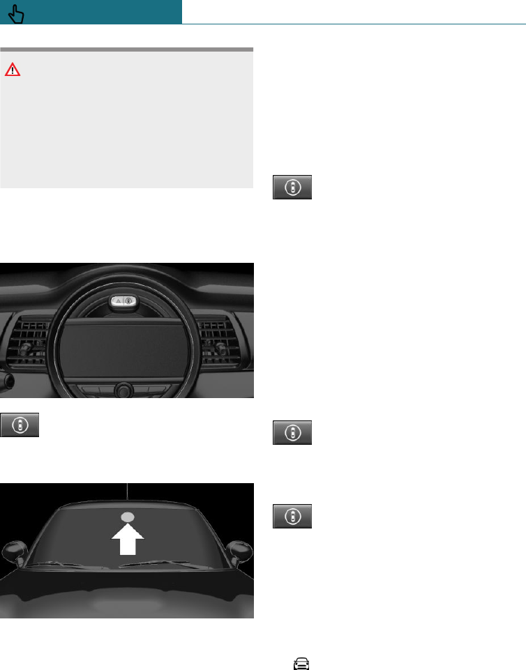
WARNING
Due to system limitations, individual func-
tions may not work properly when tow
starting/towing with activated Intelligent
Safety Systems. There is a danger of acci-
dents. Switch off all Intelligent Safety Sys-
tems before tow-starting/towing.
Overview
Button in the vehicle
Intelligent Safety button
Camera
The camera is located on the front side of
the rearview mirror.
Keep the windscreen clean and clear in the
area in front of the rearview mirror.
Switching on/off
Switching on automatically
The system is automatically activated at the
start of each journey.
Switching on/off manually
Press the button briefly:
–The menu for the Intelligent
Safety Systems is shown. The
systems are switched off indi-
vidually depending on the indi-
vidual setting.
–LED illuminates orange or is extin-
guished, depending on individual set-
ting.
Press the button twice if necessary to
switch off the Lane Departure Warning.
Settings can be performed. The individual
settings are saved for the currently used
driver profile.
Press the button again:
–All Intelligent Safety Systems
are switched on.
–The LED is illuminated green.
Press and hold down the button:
–All Intelligent Safety Systems
are switched off.
–The LED is extinguished.
Setting the warning time
The warning time can be set using on-board
monitor.
1. "My MINI"
2. "Vehicle settings"
3. "Intelligent Safety"
4. "Warning point"
5. Select the desired setting.
Seite 162
CONTROLS Safety
162 Online Edition for Part no. 01402988211 - II/18
Draft
from BA-76
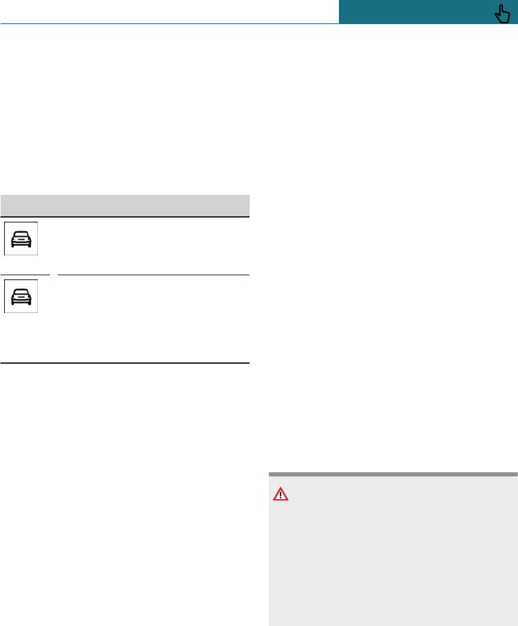
The selected warning time is saved for the
currently used driver profile.
Warning with braking function
Display
If there is a risk of collision with a detected
vehicle, a warning symbol is shown in the
instrument cluster.
Symbol Measure
Symbol illuminates red: advance
warning.
Brake and increase the distance.
Symbol flashes red and an
acoustic signal sounds: acute
warning.
Brake and perform an evasive
manoeuvre, if necessary.
Advance warning
An advance warning is shown, for example
if a danger of collision is anticipated or
there is a very short distance to a vehicle
ahead.
The driver must intervene personally if
there is an acute warning.
Acute warning with braking function
An acute warning is given when the vehicle
is approaching another object at a high dif-
ferential speed and there is an immediate
risk of a collision.
The driver must intervene personally if
there is an acute warning. If necessary, the
driver is assisted by slight automatic brake
intervention if there is a risk of collision.
An acute warning can be triggered even
without a previous advance warning.
Brake intervention
The warning prompts the driver to inter-
vene actively. Maximum braking force is
used during a warning. In order for braking
force support to be used, it is necessary for
the brake to be pressed sufficiently quickly
and firmly. The system can also assist by ap-
plying the brakes lightly if there is the risk
of a collision. At low speeds, the vehicle can
be braked to a stop.
Manual gearbox: when the vehicle is braked
to a stop, the engine may shut off.
The brakes are only applied if driving stabil-
ity has not been impaired, for example by
deactivation of Dynamic Stability Control
DSC.
Braking can be discontinued either by de-
pressing the accelerator pedal or by actively
moving the steering wheel.
The detection of objects may be limited.
Take into account the detection range limits
and the functional limitations.
System limits
Safety note
WARNING
The system may not respond at all, or may
respond too late, incorrectly, or without
justification due to limits of the system.
There is a danger of accidents or damage
to property. Observe the information on
the system limits and intervene actively if
necessary.
Detection range
The detection ability of the system is limi-
ted.
For this reason, the system may fail to re-
spond or only respond after a delay.
Seite 163
Safety CONTROLS
163
Online Edition for Part no. 01402988211 - II/18
Draft
from BA-76
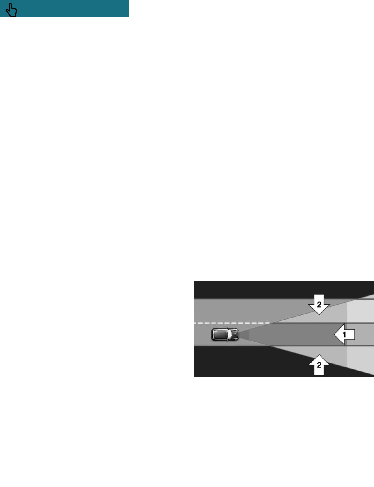
It is possible that the following are not de-
tected:
–Slow-moving vehicle when approaching
at high speed.
–Vehicles suddenly cutting in or braking
heavily.
–Vehicles with an unusual rear appear-
ance.
–Two-wheeled vehicles ahead.
Functional limitations
The system may have limited functionality
in the following situations, for example:
–In thick fog, wet conditions or snow.
–On sharp bends.
–If the field of view of the camera or the
windscreen is dirty or covered.
–If vehicle stability control systems are
deactivated, for example DSC OFF.
–Up to 10 seconds after starting the en-
gine using the start/stop button.
–During the camera calibration process
immediately after vehicle delivery.
–When there is sustained glare effect due
to oncoming light, for example the sun
is low in the sky.
Sensitivity of the warnings
The greater the sensitivity of the warning
settings, the more warnings will be dis-
played. As a result, there may be an in-
creased number of premature or unjustified
warnings and reactions.
Person warning with City
light braking function
Principle
The system can help to avoid accidents with
pedestrians.
The system warns of the possible risk of
collision with pedestrians in the urban
speed range and provides assistance with a
light braking function.
The system is controlled by the camera at
the base of the rearview mirror.
General
Provided that the light conditions are suffi-
ciently bright, the system operates and is-
sues warnings from approximately 10 km/h,
approximately 6 mph up to approximately
60 km/h, approximately 35 mph if there is a
risk of collision with pedestrians and pro-
vides assistance by briefly applying the
brakes before a collision.
Persons are taken into account if they are
located within the detection range of the
system.
Detection range
The detection zone in front of the vehicle
consists of two parts:
–Central zone, arrow 1, directly in front
of the vehicle.
–Extended zone, arrow 2, to the right and
left of the central area.
There is a risk of collision if persons are in
the central zone. A warning is only given of
persons in the extended zone if they are
moving towards the central zone.
Seite 164
CONTROLS Safety
164 Online Edition for Part no. 01402988211 - II/18
Draft
from BA-76
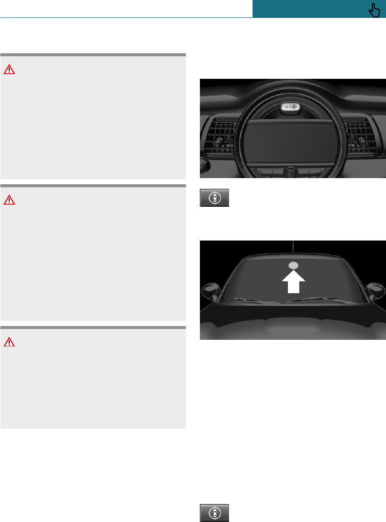
Safety notes
WARNING
The system does not relieve you of your
personal responsibility to assess the visi-
bility conditions and traffic situation cor-
rectly. There is a danger of accidents.
Adapt your driving style to the traffic con-
ditions. Observe the traffic situation and
intervene actively if the situation warrants
it.
WARNING
Displays and warnings do not relieve you
of personal responsibility. System limita-
tions can mean that warnings or system
responses are not issued or are issued too
late, incorrectly, or without justification.
There is a danger of accidents. Adapt your
driving style to the traffic conditions. Ob-
serve the traffic situation and intervene
actively if the situation warrants it.
WARNING
Due to system limitations, individual func-
tions may not work properly when tow
starting/towing with activated Intelligent
Safety Systems. There is a danger of acci-
dents. Switch off all Intelligent Safety Sys-
tems before tow-starting/towing.
Overview
Button in the vehicle
Intelligent Safety button
Camera
The camera is located on the front side of
the rearview mirror.
Keep the windscreen clean and clear in the
area in front of the rearview mirror.
Switching on/off
Switching on automatically
The system is automatically activated at the
start of each journey.
Switching on/off manually
Press the button briefly:
–The menu for the Intelligent
Safety Systems is shown. The
systems are switched off indi-
Seite 165
Safety CONTROLS
165
Online Edition for Part no. 01402988211 - II/18
Draft
from BA-76
vidually depending on the indi-
vidual setting.
–LED illuminates orange or is extin-
guished, depending on individual set-
ting.
Press the button twice if necessary to
switch off the Lane Departure Warning.
Settings can be performed. The individual
settings are saved for the currently used
driver profile.
Press the button again:
–All Intelligent Safety Systems
are switched on.
–The LED is illuminated green.
Press and hold down the button:
–All Intelligent Safety Systems
are switched off.
–The LED is extinguished.
Warning with braking function
Display
If there is a risk of collision with a detected
person, a warning symbol is shown in the
instrument cluster.
A red symbol is displayed and an
acoustic warning sounds.
Take action yourself immediately, by
braking or swerving.
Brake intervention
The warning prompts the driver to inter-
vene actively. Maximum braking force is
used during a warning. In order for braking
force support to be used, it is necessary for
the brake to be pressed sufficiently quickly
and firmly. The system can also assist by ap-
plying the brakes lightly if there is the risk
of a collision. At low speeds, the vehicle can
be braked to a stop.
Manual gearbox: when the vehicle is braked
to a stop, the engine may shut off.
The brakes are only applied if driving stabil-
ity has not been impaired, for example by
deactivation of Dynamic Stability Control
DSC.
Braking can be discontinued either by de-
pressing the accelerator pedal or by actively
moving the steering wheel.
The detection of objects may be limited.
Take into account the detection range limits
and the functional limitations.
System limits
Safety note
WARNING
The system may not respond at all, or may
respond too late, incorrectly, or without
justification due to limits of the system.
There is a danger of accidents or damage
to property. Observe the information on
the system limits and intervene actively if
necessary.
Detection range
The detection capacity of the camera is
limited.
As a result, the system may fail to give
warnings or may give warnings late.
It is possible that the following are not de-
tected:
–Partially concealed pedestrians.
–Pedestrians who are not detected as
such, because of the viewing angle or
outline.
–Pedestrians outside the detection range.
–Pedestrians less than approximately
80 cm, 32 in tall.
Seite 166
CONTROLS Safety
166 Online Edition for Part no. 01402988211 - II/18
Draft
from BA-76
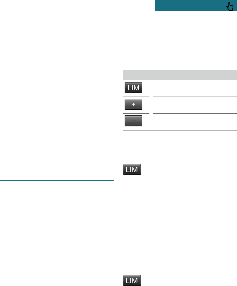
Functional limitations
The system may have limited functionality
in some situations, for example:
–In thick fog, wet conditions or snow.
–On sharp bends.
–If the field of view of the camera or the
windscreen is dirty or covered.
–If vehicle stability control systems are
deactivated, for example DSC OFF.
–Up to 10 seconds after starting the en-
gine using the start/stop button.
–During the camera calibration process
immediately after vehicle delivery.
–When there is sustained glare effect due
to oncoming light, for example the sun
is low in the sky.
–In the dark.
Manual speed limiter
Principle
The system enables speeds from a value of
30 km/h/20 mph and above to be set as a
speed limit. Below the set speed limit, the
vehicle can be driven without restriction.
Exceeding the speed limit
In particular situations the speed limit can
be deliberately exceeded by accelerating.
The system gives a warning if the travelling
speed exceeds the set speed limit.
No brake intervention
If the set speed limit has been reached or
unintentionally exceeded, for example when
driving downhill, there is no active brake
intervention.
If you set a speed limit whilst driving which
is below the current speed, the vehicle rolls
until driving speed drops below the speed
limit.
Overview
Buttons on steering wheel, left
Button Function
System on/off.
Increase the speed limit.
Decrease the speed limit.
Operation
Switching on
Press the button on the steering
wheel.
The current speed is adopted as the speed
limit.
When switching on at a standstill or driving
at low speed, 30 km/h/20 mph is set as the
speed limit.
The set speed is shown under the display
LIMIT.
When activating the speed limit it is possi-
ble that Dynamic Stability Control, DSC is
activated.
Switching off
Press the button on the steering
wheel.
The system switches off automatically in
the following situations, for example:
–When engaging reverse gear.
–When switching the engine off.
–When switching on Cruise Control.
Seite 167
Safety CONTROLS
167
Online Edition for Part no. 01402988211 - II/18
Draft
from BA-76
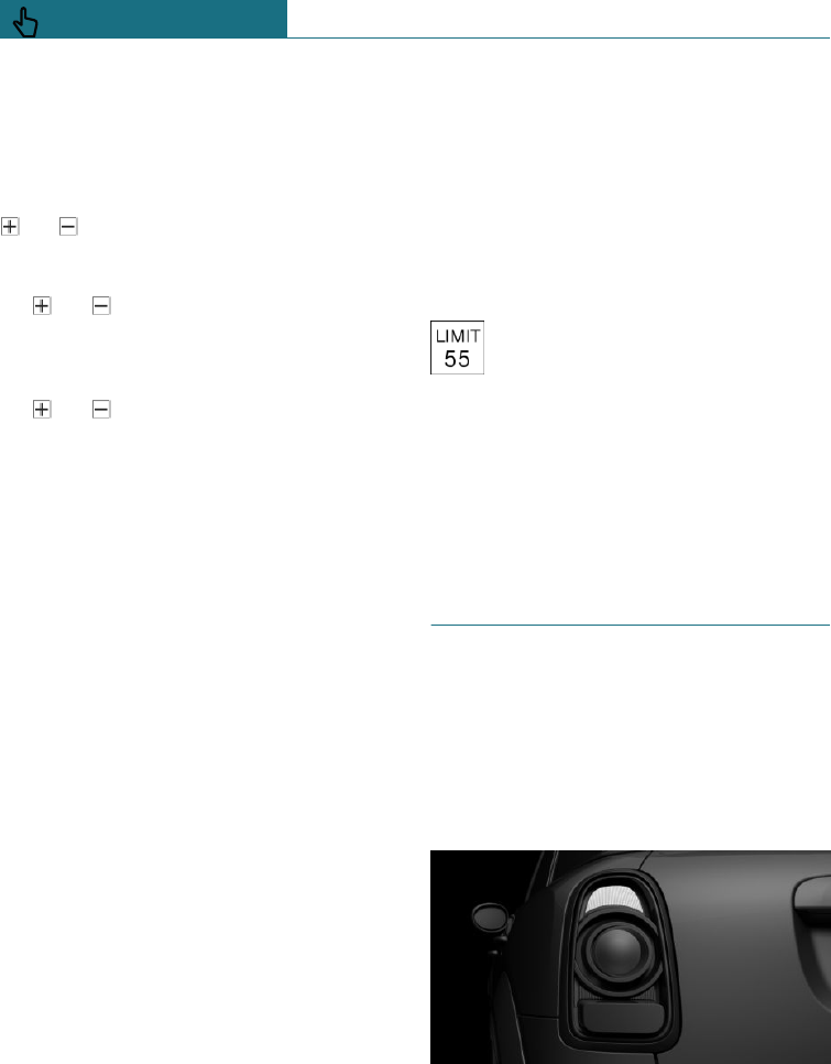
–When activating the Dynamic Traction
Control DTC or deactivating DSC.
The displays turn off.
Change speed limit
or button: press the paddle repeat-
edly upwards or downwards until the de-
sired speed limit is set.
– or button: every time it is
pressed to the resistance point, the
speed limit is increased or decreased by
1 km/h, 1 mph.
– or button: each time the button is
pressed beyond the resistance point, the
desired speed limit is increased or de-
creased to the next multiple of 10 km/h
on the speedometer display.
If you set a speed limit while driving which
is below the current speed, the vehicle
coasts down to the set speed limit.
Exceeding the speed limit
You can intentionally exceed the speed
limit. There is no acoustic warning in such a
case.
To exceed the set speed limit intentionally,
fully depress the accelerator pedal.
The limit automatically becomes active
again as soon as the current speed falls be-
low the set speed limit.
Warning when the speed limit is
exceeded
Visual warning
When the set speed limit is exceeded, the
LIMIT display in the instrument cluster
flashes for as long as you exceed the limit.
Acoustic warning
–A signal sounds if you inadvertently ex-
ceed the set speed limit.
–If the speed limit is reduced to below
the driven speed during the journey, the
warning sounds after approximately
30 seconds.
–If you intentionally exceed the speed
limit by fully pressing the accelerator
pedal, no warning is given.
Displays in the instrument cluster
The desired speed is shown under
the display LIMIT.
–Display does not illuminate: the
system is inactive.
–Display illuminates green: system is ac-
tive.
–Display flashes green: set speed limit ex-
ceeded.
Dynamic brake lights
Principle
The brake lights flash to warn road users
behind your vehicle that you are performing
an emergency braking manoeuvre. This can
reduce the risk of a rear-end collision.
General
–Normal braking: brake lights illuminate.
–Heavy braking: brake lights flash.
Seite 168
CONTROLS Safety
168 Online Edition for Part no. 01402988211 - II/18
Draft
from BA-76

Shortly before the vehicle comes to a stand-
still, the hazard warning lights are activa-
ted.
To deactivate the hazard warning lights:
–Accelerate.
–Press the hazard warning lights button.
PostCrash – iBrake
Principle
The system can automatically bring the ve-
hicle to a standstill in certain accident sit-
uations without the involvement of the
driver. The risk of a further collision and its
consequences can thereby be reduced.
At a standstill
After the vehicle has come to a halt, the
brake is released automatically. The vehicle
should then be secured to prevent it from
rolling away.
Harder vehicle braking
In certain situations, it may be necessary to
bring the vehicle to a standstill more
quickly.
To do this, for a short time the braking pres-
sure applied when stepping on the brake
pedal must be higher than the braking pres-
sure achieved by the automatic braking
function. The automatic braking process is
interrupted as a result.
Cancelling automatic braking
In certain situations, it may be necessary to
cancel automatic braking, for example for
an evasive manoeuvre.
Cancel automatic braking:
–By depressing the brake pedal.
–By depressing the accelerator pedal.
Seite 169
Safety CONTROLS
169
Online Edition for Part no. 01402988211 - II/18
Draft
from BA-76
Driving Stability Control Systems
Vehicle equipment
This chapter describes all standard, country-
specific and special equipment available for
the model series. Therefore equipment
which is not installed in your vehicle, for
example on account of the optional equip-
ment selected or the country specification,
may also be described here. This also ap-
plies to safety-relevant functions and sys-
tems. Comply with the relevant laws and
regulations when using the corresponding
functions and systems.
Anti-lock Brake System, ABS
ABS prevents the wheels from locking when
the brakes are applied.
Steering control is retained even in the
event of full braking, thereby enhancing ac-
tive road safety.
ABS is ready to operate each time the en-
gine is started.
Brake assist
When the brake is pressed quickly, this sys-
tem automatically applies maximum braking
power assistance. With full braking, this
keeps the braking distance as short as pos-
sible. It also makes full use of the advan-
tages offered by the Anti-lock Brake System
ABS.
The pressure on the brake should be main-
tained for the duration of the full-braking
process.
Dynamic Stability Control DSC
Principle
The system reduces engine output and ap-
plies the brakes on individual wheels
thereby helping, within the limits imposed
by the laws of physics, to keep the vehicle
safely on course.
General
DSC detects the following unstable driving
conditions, for example:
–Loss of traction at the rear which can
lead to oversteer.
–Loss of grip of the front wheels which
can lead to understeer.
Dynamic Traction Control DTC, see
page 171, is a variant of DSC optimised for
forward momentum.
Safety notes
WARNING
The system does not relieve you of your
personal responsibility to assess the traffic
situation correctly. Due to system limita-
tions, it cannot respond independently and
appropriately in all traffic conditions.
There is a danger of accidents. Adapt your
driving style to the traffic conditions. Ob-
serve the traffic situation and intervene
actively if the situation warrants it.
WARNING
When driving with a roof load, for example
with a roof rack, the higher centre of grav-
ity can mean that driving safety is no lon-
ger guaranteed in critical driving situa-
Seite 170
CONTROLS Driving Stability Control Systems
170 Online Edition for Part no. 01402988211 - II/18
Draft
from BA-76
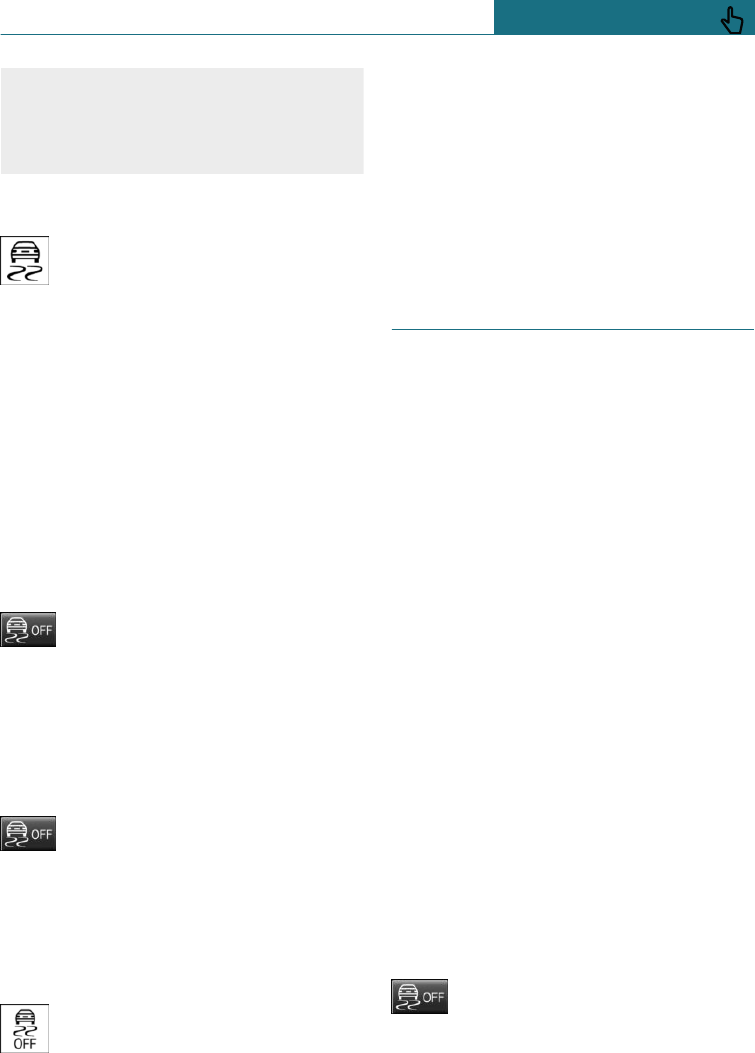
tions. There is a danger of accidents or
damage to property. Do not deactivate Dy-
namic Stability Control DSC when driving
with a roof load.
Indicator and warning lamps
If the indicator lamp is flashing: DSC
is regulating the acceleration and
braking forces.
If the indicator lamp is illuminated: DSC has
failed.
Deactivating DSC: DSC OFF
General
Driving stability during acceleration and
cornering is restricted if DSC is deactivated.
To assist driving stability, re-activate DSC
as soon as possible.
Deactivating DSC
Press and hold the button – but for
no longer than approximately
10 seconds – until the DSC OFF in-
dicator lamp in the instrument cluster is il-
luminated and DSC OFF is displayed.
DSC is switched off.
Activating DSC
Press the button.
DSC OFF and the DSC OFF indicator
lamps are extinguished.
Indicator and warning lamps
DSC OFF is displayed in the instrument
cluster when DSC is deactivated.
If the indicator lamp is illuminated:
DSC is deactivated.
Automatic activation
If DSC is deactivated, it is automatically ac-
tivated in the following situations:
–In the event of a flat tyre.
–If Cruise Control is activated in TRAC-
TION mode or with DSC OFF.
Dynamic Traction Control
DTC
Principle
DTC is a variant of Dynamic Stability Con-
trol DSC and is optimised for forward mo-
mentum.
In particular road conditions, for example
roads on which snow has not been cleared
or unconsolidated ground, the system en-
sures maximum forward momentum but
with somewhat limited driving stability.
Activating DTC provides maximum traction.
Driving stability during acceleration and
cornering is limited.
Drive carefully.
It may be useful to activate DTC briefly in
the following exceptional situations:
–When driving in slush or on uncleared,
snow-covered roads.
–Starting in deep snow or on a loose sur-
face.
–Driving with snow chains.
Deactivating/activating Dynamic
Traction Control DTC
Activating DTC
Press the button.
TRACTION is displayed in the in-
strument cluster and the DSC OFF indicator
lamp is illuminated.
Seite 171
Driving Stability Control Systems CONTROLS
171
Online Edition for Part no. 01402988211 - II/18
Draft
from BA-76
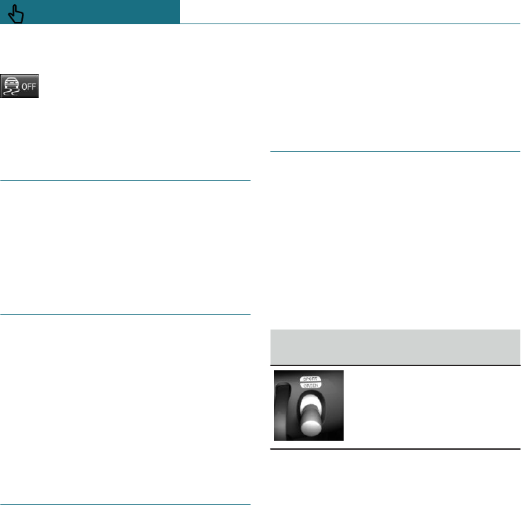
Deactivating DTC
Press the button again.
TRACTION and the DSC OFF indica-
tor light are extinguished.
Performance Control
Performance Control increases the agility of
the vehicle.
Individual wheels are braked to increase
agility for a sporty driving style.
ALL4
ALL4 is the four-wheel drive system avail-
able in your vehicle. The combination of
ALL4 and Dynamic Stability Control DSC
further optimises traction and driving dy-
namics. The ALL4 four-wheel drive system
distributes the drive forces variably to the
front and rear axles based on the driving sit-
uation and the condition of the road.
Adaptive suspension
Principle
The system enables the suspension set-up
to be changed.
It provides different programs.
The programmes can be selected via the
MINI Driving Modes switch.
Programs
MID/GREEN
Balanced shock absorber set-up for greater
comfort.
SPORT
A consistently sporty shock absorber set-up
for greater agility when driving.
MINI Driving Modes switch
Principle
With the MINI Driving Mode switch, cer-
tain properties of the vehicle can be adjus-
ted. Three different programs can be selec-
ted for this.
A particular programme is activated by
pressing the MINI Driving Modes switch.
Operating the programs
MINI Driving Modes
switch Programme
SPORT
MID
GREEN
MID
MID provides balanced tuning.
MID is activated every time the vehicle is
started via the start/stop button.
GREEN
Principle
GREEN, see page 238, offers a consistently
fuel-efficient set-up consumption, in order
to achieve maximum range.
Activating GREEN
Press the MINI Driving Modes switch
downwards until GREEN is displayed in the
instrument cluster.
Seite 172
CONTROLS Driving Stability Control Systems
172 Online Edition for Part no. 01402988211 - II/18
Draft
from BA-76
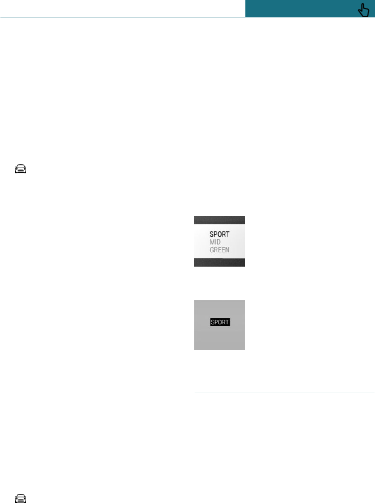
Configuring GREEN
Using MINI Driving Modes switch
1. Activate GREEN.
2. "Configure GREEN"
3. Configure the program.
This configuration is called up when
GREEN is activated.
Using the on-board monitor
1. "My MINI"
2. "Vehicle settings"
3. If necessary, "Driving mode"
4. "Configure GREEN"
5. Select the desired setting.
This configuration is called up when
GREEN is activated.
SPORT
Principle
A consistently sporty drive system set-up
for greater agility when driving.
Depending on the equipment installed, the
suspension set-up additionally changes and
SPORT can be individually configured.
The configuration is saved for the currently
used driver profile.
Activate SPORT
Press the MINI Driving Modes switch up-
wards until SPORT is displayed in the in-
strument cluster.
Configuring SPORT
Using the on-board monitor:
1. "My MINI"
2. "Vehicle settings"
3. If necessary, "Driving mode"
4. "Configure SPORT"
5. Select the desired setting.
This configuration is called up when SPORT
is activated.
Configuring drive program
Under "Configure drive mode", settings for
the following drive programs can be made:
–GREEN, see page 172.
–SPORT, see page 173.
Displays
Programme selection
When the MINI Driving
Modes switch is pressed, a list
of selectable programmes is
shown.
Selected programme
The selected program is
shown in the instrument clus-
ter.
Drive-off assistant
Principle
The system provides support when driving
off on upward gradients. It is not necessary
to use the parking brake for this.
Driving off with drive-off assistant
1. Hold the vehicle in place by depressing
the foot brake.
2. Release the foot brake and drive off
without delay.
Seite 173
Driving Stability Control Systems CONTROLS
173
Online Edition for Part no. 01402988211 - II/18
Draft
from BA-76

The vehicle is held for approximately 2 sec-
onds after the foot brake has been released.
Servotronic
Servotronic is a speed-dependent power
steering system.
The system provides more steering force as-
sistance at lower speeds than at higher
speeds. This makes it easier to park, for ex-
ample, and provides a more direct steering
feel when driving at higher speeds.
In addition, the steering force is adapted ac-
cording to the drive programme, so that a
direct, sporty feel or a comfortable steering
response is conveyed.
Seite 174
CONTROLS Driving Stability Control Systems
174 Online Edition for Part no. 01402988211 - II/18
Draft
from BA-76
Driving comfort
Vehicle equipment
This chapter describes all standard, country-
specific and special equipment available for
the model series. Therefore equipment
which is not installed in your vehicle, for
example on account of the optional equip-
ment selected or the country specification,
may also be described here. This also ap-
plies to safety-relevant functions and sys-
tems. Comply with the relevant laws and
regulations when using the corresponding
functions and systems.
Camera-based Cruise Control
Principle
This system allows you to set a desired
speed and a desired distance from the vehi-
cle in front, using the buttons on the steer-
ing wheel.
When the road ahead is clear, the system
maintains the desired speed by braking or
accelerating the vehicle automatically, as
required.
If there is a vehicle driving in front, the sys-
tem adapts your own vehicle's speed in or-
der to maintain the set distance from the
vehicle ahead. The speed is adapted as far
as the given situation allows.
The distance can be set in several stages,
and is dependent on the particular speed for
reasons of safety.
With the Stop&Go function and Steptronic
transmission: if the vehicle ahead brakes to
a standstill and sets off again shortly after-
wards, the system can comprehend this
within the given context.
General
A camera on the rearview mirror is used to
detect a vehicle in front.
Characteristics of Cruise Control may
change in certain areas depending on vehi-
cle setting.
Safety notes
WARNING
The system does not relieve you of your
personal responsibility to assess the traffic
situation correctly. Due to system limita-
tions, it cannot respond independently and
appropriately in all traffic conditions.
There is a danger of accidents. Adapt your
driving style to the traffic conditions. Ob-
serve the traffic situation and intervene
actively if the situation warrants it.
WARNING
The desired speed can be inadvertently set
or called up incorrectly. There is a danger
of accidents. Adjust the desired speed to
the traffic conditions. Observe the traffic
situation and intervene actively if the sit-
uation warrants it.
WARNING
There is a danger of accidents if the differ-
ence in speed relative to other vehicles is
excessively high. This may occur, for ex-
ample, in the following situations:
–When quickly approaching a slowly
moving vehicle.
–If another vehicle suddenly veers into
the vehicle's own lane.
Seite 175
Driving comfort CONTROLS
175
Online Edition for Part no. 01402988211 - II/18
Draft
from BA-76
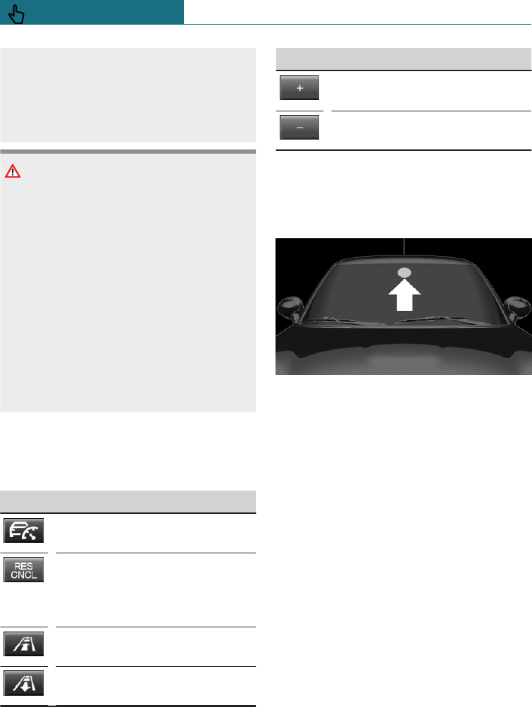
–When quickly approaching stationary
vehicles.
There is a danger of injury or even death.
Observe the traffic situation and intervene
actively if the situation warrants it.
WARNING
An unsecured vehicle can start moving
and rolling away. There is a danger of acci-
dents. Before leaving the vehicle, secure it
to prevent it from rolling away.
Observe the following to ensure that the
vehicle is secured against rolling away:
–Apply the parking brake.
–Turn the front wheels towards the
kerb on upward or downward gradi-
ents.
–Additionally secure the vehicle on up-
ward or downward gradients, for ex-
ample with a chock.
Overview
Buttons on the steering wheel
Button Function
Cruise Control on/off, see
page 177.
To interrupt Cruise Control, see
page 177.
To resume Cruise Control with
last setting, see page 178.
Reduces the distance, see
page 178.
To increase the distance, see
page 178.
Button Function
Increases the speed, see
page 177.
Decreases the speed, see
page 177.
The arrangement of buttons varies depend-
ing on equipment or country version.
Camera
The camera is located on the front side of
the rearview mirror.
Keep the windscreen clean and clear in the
area in front of the rearview mirror.
Operating requirements
Speed range
The system can be used to optimum effect
on well-constructed roads.
The system is operational from a speed of
approximately 30 km/h/20 mph.
With the Stop&Go function and Steptronic
transmission: the system can also be activa-
ted when the vehicle is at a standstill.
The maximum speed that can be set is
140 km/h/85 mph.
Manual gearbox: Active Cruise Control is in-
terrupted below approx. 30 km/h, approx.
20 mph. The system does not brake to a
standstill.
Seite 176
CONTROLS Driving comfort
176 Online Edition for Part no. 01402988211 - II/18
Draft
from BA-76
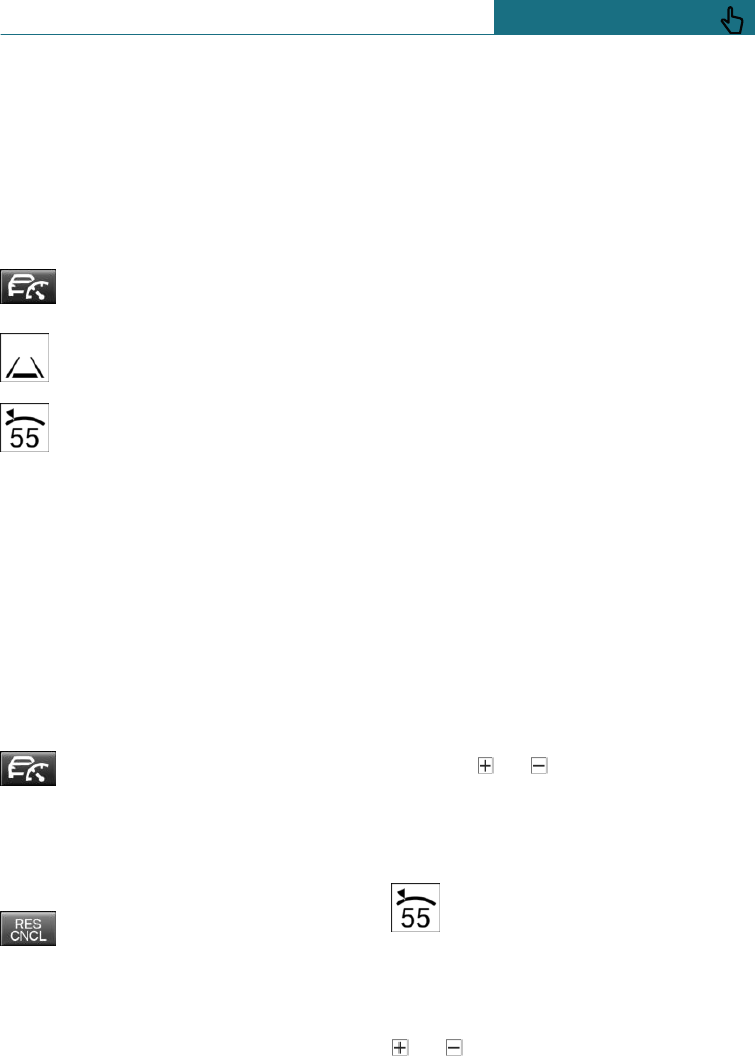
Faster desired speeds can also be selected if
distance control is switched off, see
page 179.
Switching the Cruise Control on/off
and interrupting
Switching on
Press the button on the steering
wheel.
Display in the instrument cluster il-
luminates.
Display in the instrument cluster il-
luminates. The current speed is ac-
cepted as the desired speed and
shown on the symbol.
Cruise Control is active and holds the set
speed.
Dynamic Stability Control DSC is switched
on, if necessary.
Switching off
With the Stop&Go function and Steptronic
transmission: when switching off with the
vehicle at a standstill, depress the brake
pedal at the same time.
Press the button on the steering
wheel.
The displays turn off. The saved desired
speed is deleted.
Interrupting manually
Press the button on the steering
wheel.
With the Stop&Go function and Steptronic
transmission: if you interrupt the system
when the vehicle is at a standstill, depress
the brake pedal at the same time.
Interrupting automatically
The system interrupts automatically in the
following situations:
–If the driver applies the brakes.
–Manual gearbox: if the clutch is pressed
for a few seconds or released with no
gear engaged.
–If selector lever position N is engaged.
–If Dynamic Traction Control DTC is acti-
vated or Dynamic Stability Control DSC
deactivated.
–If Dynamic Stability Control DSC inter-
venes.
–If the detection zone of the camera is
disrupted, for example, due to dirt,
heavy rainfall or dazzling by the sun.
–Manual gearbox: if the vehicle in front
brakes at speeds below approx. 30 km/h,
approx. 20 mph.
–With the Stop&Go function and Step-
tronic transmission: after a stationary
period of approximately 3 seconds, if the
vehicle was decelerated by the system
to a standstill.
Setting the speed
Holding or setting the speed
Press the or button while the sys-
tem is interrupted.
If the system is switched on, the current
speed is maintained and saved as the de-
sired speed.
The saved speed is shown on the
symbol.
Dynamic Stability Control DSC is
switched on, if necessary.
Changing the speed
or button: press repeatedly until the
desired speed is set.
Seite 177
Driving comfort CONTROLS
177
Online Edition for Part no. 01402988211 - II/18
Draft
from BA-76
If the system is active, the displayed speed
is stored and the vehicle reaches the stored
speed when the road is clear.
– or button: every time it is
pressed to the resistance point, the de-
sired speed is increased or decreased by
approximately 1 km/h, approximately
1 mph.
– or button: each time the button is
pressed beyond the resistance point, the
desired speed changes to the next multi-
ple of 10 km/h on the speedometer dis-
play.
or button: keep pressed to repeat the
action.
Adjusting the distance
Safety note
WARNING
The system does not relieve you of your
personal responsibility. Braking may be
performed too late because of system limi-
tations. There is a danger of accidents or
damage to property. Observe the traffic
conditions attentively at all times. Adapt
the distance to traffic and weather condi-
tions, also comply with the prescribed safe
distance by braking if necessary.
Reducing the distance
Press the button repeatedly until
the desired distance is set.
The set distance is briefly shown in
the left part of the instrument clus-
ter.
Increase the distance
Press the button repeatedly until
the desired distance is set.
The set distance is briefly shown in
the left part of the instrument clus-
ter.
Resuming Cruise Control
General
If Cruise Control is interrupted, it can be re-
sumed by calling up the saved speed.
Before calling up the saved speed, make
sure that the difference between the cur-
rent speed and the saved speed is not exces-
sively large. Otherwise, there may be inad-
vertent braking or acceleration.
The saved speed value is deleted and can no
longer be called up in the following instan-
ces:
–When the system is switched off.
–When the ignition is switched off.
Resuming the saved speed and
distance
While the system is interrupted,
press the button. Cruise Control is
resumed with the saved values. The
selected distance is briefly displayed on the
Info Display.
Switching distance control off/on
Safety note
WARNING
The system does not react to traffic travel-
ling in front of you, but maintains the
saved speed. There is a danger of acci-
dents or damage to property. Adjust the
desired speed to the traffic conditions and
brake if necessary.
Seite 178
CONTROLS Driving comfort
178 Online Edition for Part no. 01402988211 - II/18
Draft
from BA-76
Switching distance control off
Distance control can be switched off and on
when driving with Cruise Control activated.
Press and hold the button.
Or:
Press and hold the button.
The indicator lamp in the instrument
cluster is illuminated.
Press one of the two buttons briefly to
switch the distance control back on.
A Check Control message is displayed after
changing over the distance control.
Displays in the instrument cluster
Desired speed and saved speed
In addition to the indicator lamp, the
desired speed is shown in the infor-
mation display.
–Display illuminates green: system is ac-
tive, the display shows the desired
speed.
–Display illuminates orange: system is in-
terrupted, the display shows the saved
speed.
–No display: system is switched off.
If no speed is displayed, the conditions re-
quired for operation may not be fulfilled at
the present time.
Vehicle distance
The selected distance from the vehicle in
front is briefly shown in the left part of the
information display.
Distance indicator
Distance 1
Distance 2
Distance 3
Automatically set after switching
on the system. Corresponds to ap-
proximately half of the value of
the speedometer reading, ex-
pressed in metres.
Distance 4
Detected vehicle
Symbol illuminates orange:
Preceding vehicle detected.
With the Stop&Go function and Step-
tronic transmission:
Rolling bars: the detected vehicle
has driven off.
ACC does not accelerate. To accelerate, acti-
vate ACC as follows:
–By briefly pressing the accelerator
pedal.
–By pressing the RES CNCL button.
–By pressing the or button.
Indicator and warning lamps
Symbol flashes orange:
The requirements for operation of
the system are no longer being met.
The system has been deactivated but will
continue to brake until you actively take
over by depressing the brake or the acceler-
ator pedal.
Seite 179
Driving comfort CONTROLS
179
Online Edition for Part no. 01402988211 - II/18
Draft
from BA-76
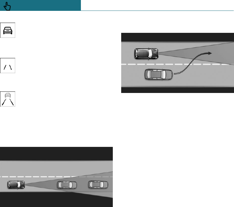
Symbol flashes red and an acoustic
signal sounds:
Brake and perform an evasive ma-
noeuvre, if necessary.
System interrupted or distance con-
trol briefly disabled because the ac-
celerator pedal is pressed although a
vehicle is not detected.
Distance control briefly disabled be-
cause the accelerator pedal is
pressed while a vehicle is detected.
System limits
Detection range
The system's detection capability and auto-
matic braking capacity are limited.
For example, two-wheeled vehicles may not
be detected.
Deceleration
The system does not decelerate in the
following situations:
–Pedestrians, cyclists or similar slow road
users.
–For red traffic lights.
–For crossing traffic.
–For oncoming vehicles.
–Unlit vehicles or vehicles with faulty
lighting at night.
Vehicles pulling out
A vehicle driving ahead of you is only detec-
ted when it is fully in your driving path.
If another vehicle suddenly pulls out in
front of you, the system might not be able
to re-establish the selected distance of its
own accord. In some circumstances, it may
also not be possible to restore the selected
distance if you are driving significantly
faster than vehicles in front, for example
when rapidly approaching a lorry. If a vehi-
cle is clearly detected in front of you, the
system prompts you to intervene by brak-
ing, and if necessary by taking evasive ac-
tion.
With the Stop&Go function and
Steptronic transmission: driving off
The vehicle cannot drive off automatically
in the following situations, for example:
–On steep upward gradients.
–Before bumps or rises in the road.
–When towing a heavy trailer.
In such cases, press accelerator pedal.
Seite 180
CONTROLS Driving comfort
180 Online Edition for Part no. 01402988211 - II/18
Draft
from BA-76
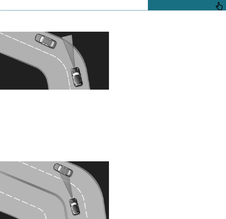
Cornering
If the desired speed is too high for corner-
ing, it will be reduced slightly in the corner.
However, the system does not detect cor-
ners in advance. For this reason, moderate
your speed when cornering.
The system has a limited detection range.
Situations can arise on tight bends where a
vehicle driving in front will not be detected
or will be detected very late.
When your vehicle is approaching a bend,
the angle of the bend may cause the system
to respond temporarily to vehicles in the
other lane. A possible reduction in the vehi-
cle's speed by the system can be compensa-
ted for by briefly accelerating. When the ac-
celerator pedal is released again, the system
will resume control of the vehicle's speed.
Weather
The following restrictions may apply if the
weather or lighting conditions are unfav-
ourable:
–Impaired detection of vehicles.
–Brief interruptions when vehicles have
already been detected.
Examples of unfavourable weather or light-
ing conditions:
–Wet roads.
–Snowfall.
–Slush.
–Fog.
–Oncoming light.
Pay attention when driving and respond to
the prevailing traffic conditions. If neces-
sary, intervene actively, for example by
braking, steering or manoeuvring.
Engine power
The vehicle may drive slower than the de-
sired speed on gradients, if the engine
power is not sufficient.
Malfunction
A Check Control message is displayed if the
system has failed or has been automatically
deactivated.
The system may have limited functionality
in the following situations, for example:
–If an object has not been correctly de-
tected.
–In thick fog, wet conditions or snow.
–On sharp bends.
–If the field of view of the camera or the
windscreen is dirty or covered.
–With bright oncoming light.
–Up to 20 seconds after starting the en-
gine using the start/stop button.
–During the camera calibration process
immediately after vehicle delivery.
Seite 181
Driving comfort CONTROLS
181
Online Edition for Part no. 01402988211 - II/18
Draft
from BA-76
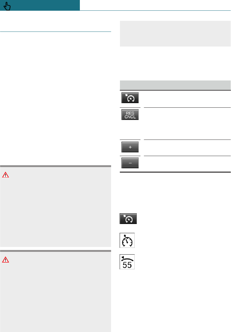
Cruise Control
Principle
This system allows a desired speed to be set
using the buttons on the steering wheel.
The desired speed is then maintained by the
system. To do this, the system automatically
accelerates and brakes the vehicle as neces-
sary.
General
The system is operational from a speed of
approximately 30 km/h, approximately
20 mph.
Characteristics of Cruise Control may
change in certain areas depending on vehi-
cle setting.
Safety notes
WARNING
The system does not relieve you of your
personal responsibility to assess the traffic
situation correctly. Due to system limita-
tions, it cannot respond independently and
appropriately in all traffic conditions.
There is a danger of accidents. Adapt your
driving style to the traffic conditions. Ob-
serve the traffic situation and intervene
actively if the situation warrants it.
WARNING
Using the system in the following situa-
tions may increase the risk of an accident,
for example:
–On stretches of road with many cor-
ners and bends.
–In heavy traffic.
–If the road is icy, if there is fog or
snow, if conditions are wet or on a
loose road surface.
There is a danger of accidents or damage
to property. Only use the system if it is
possible to drive at a constant speed.
Overview
Buttons on the steering wheel
Button Function
Cruise Control on/off, see
page 182.
To interrupt Cruise Control, see
page 182.
To resume Cruise Control with
last setting, see page 183.
Increases speed, see page 183.
Decreases speed, see page 183.
Switching the Cruise Control on/off
and interrupting
Switching on
Press the button on the steering
wheel.
The indicator lamp in the instrument
cluster is illuminated.
The current speed is accepted as the
desired speed and shown with the
symbol in the instrument cluster.
Cruise Control is active and holds the set
speed.
Dynamic Stability Control DSC is switched
on, if necessary.
Seite 182
CONTROLS Driving comfort
182 Online Edition for Part no. 01402988211 - II/18
Draft
from BA-76
Switching off
Press the button on the steering
wheel.
The displays turn off. The saved desired
speed is deleted.
Interrupting manually
When the system is activated, press
the button on the steering wheel.
Interrupting automatically
The system interrupts automatically in the
following situations:
–If the driver applies the brakes.
–If the clutch is pressed for a few seconds
or released with no gear engaged.
–If too high a gear has been engaged for
the speed.
–If selector lever position N is engaged.
–If Dynamic Traction Control DTC is acti-
vated or Dynamic Stability Control DSC
deactivated.
–If Dynamic Stability Control DSC inter-
venes.
Setting the speed
Holding or setting the speed
Press the or button while the sys-
tem is interrupted.
If the system is switched on, the current
speed is maintained and saved as the de-
sired speed.
The saved speed is shown in the instrument
cluster.
Dynamic Stability Control DSC is switched
on, if necessary.
Changing the speed
or button: press repeatedly until the
desired speed is set.
If the system is active, the displayed speed
is stored and the vehicle reaches the stored
speed when the road is clear.
– or button: every time it is
pressed to the resistance point, the de-
sired speed is increased or decreased by
approximately 1 km/h, approximately
1 mph.
– or button: each time the button is
pressed beyond the resistance point, the
desired speed changes to the next multi-
ple of 10 km/h on the speedometer dis-
play.
– or button: pressing up to the re-
sistance point and holding it there accel-
erates or decelerates the vehicle without
the accelerator pedal being pressed. The
speed is maintained after letting go of
the switch. Pressing beyond the resist-
ance point accelerates the vehicle more
rapidly.
Resuming Cruise Control
General
If Cruise Control is interrupted, it can be re-
sumed by calling up the saved speed.
Before calling up the saved speed, make
sure that the difference between the cur-
rent speed and the saved speed is not exces-
sively large. Otherwise, there may be inad-
vertent braking or acceleration.
Resuming a saved speed
Press the button on the steering
wheel.
The saved speed is resumed and main-
tained.
Seite 183
Driving comfort CONTROLS
183
Online Edition for Part no. 01402988211 - II/18
Draft
from BA-76
Displays in the instrument cluster
Indicator lamp
Depending on the equipment the in-
dicator lamp in the instrument clus-
ter shows whether the system is
switched on.
Desired speed and saved speed
The desired speed is shown together
with the symbol.
–Display illuminates green: system
is active, the display shows the
desired speed.
–Display illuminates orange: system is in-
terrupted, the display shows the saved
speed.
–No display: system is switched off.
If no speed is displayed, the conditions re-
quired for operation may not be fulfilled at
the present time.
System limits
Engine power
The desired speed will also be maintained
on downward gradients, but may not be
reached on upward gradients if engine
power is insufficient.
Park Distance Control PDC
Principle
PDC provides assistance when parking the
vehicle. The system detects objects behind
the vehicle. If the vehicle is equipped with
front PDC, objects in front of the vehicle are
detected too. Objects being approached
slowly are indicated by acoustic signals and
a visual display.
General
The ultrasonic sensors for measuring the
distances are located in the bumpers.
Their range is approximately 2 m, approxi-
mately 6 ft depending on the obstacle and
environment.
An acoustic warning is only issued in the
following situations:
–From the centre sensors at the front and
the corner sensors at a distance of ap-
proximately 60 cm, approximately 24 in
from the object.
–From the middle sensors at the rear at a
distance of approximately 1.50 m, ap-
proximately 5 ft from the object.
–If there is a collision risk.
Safety notes
WARNING
The system does not relieve you of your
personal responsibility to assess the traffic
situation correctly. There is a danger of ac-
cidents. Adapt your driving style to the
traffic conditions. Additionally, look di-
rectly to check the traffic situation and the
area around the vehicle and intervene ac-
tively in the corresponding situations.
WARNING
If the vehicle is travelling at high speed
when Park Distance Control PDC is activa-
ted, there may be a delayed warning be-
cause of physical conditions. There is a
danger of injury or damage to property.
Avoid approaching an object at speed.
Avoid moving off at speed while Park Dis-
tance Control PDC is not yet active.
Seite 184
CONTROLS Driving comfort
184 Online Edition for Part no. 01402988211 - II/18
Draft
from BA-76
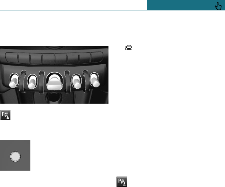
Overview
With front PDC: button in vehicle
Park Assistant button
Ultrasonic sensors
Ultrasonic sensors of the PDC,
for example in the bumpers.
Operating requirements
To ensure full functional capability:
–Do not cover sensors, for example by
stickers, bicycle rack.
–Keep the sensors clean and unobstruc-
ted.
Switching on/off
Switching on automatically
The system switches on automatically in the
following situations:
–If selector lever position R is engaged
while the engine is running.
The rearview camera also switches on.
–With front PDC equipment: if obstacles
behind or in front of the vehicle are de-
tected by PDC and the speed is slower
than approximately 4 km/h, approxi-
mately 2.5 mph.
With PDC at the front: automatic activation
for detected obstacles can be disabled. Us-
ing the on-board monitor:
1. "My MINI"
2. "Vehicle settings"
3. "Parking"
4. "Automatic PDC activation": depending
on the equipment installed.
5. "Automatic PDC activation"
The setting is saved for the currently
used driver profile.
Automatic switching off when moving
forwards
The system switches off when a certain dis-
tance or speed is exceeded.
Switch the system back on if necessary.
With front PDC: switching on/off
manually
Press the Park Assistant button.
–On: the LED is illuminated.
–Off: the LED is extinguished.
The image from the rearview camera is
shown when reverse gear is engaged and
the Park Assistant button is pressed.
Warning
Acoustic signals
An intermittent sound respectively indi-
cates the position of an object as the vehicle
approaches it. For instance, if an object is
identified to the rear left of the vehicle, the
acoustic signal is emitted from the rear left
loudspeaker.
The shorter the distance to an object, the
shorter the intervals become.
Seite 185
Driving comfort CONTROLS
185
Online Edition for Part no. 01402988211 - II/18
Draft
from BA-76
If the distance to a detected object is less
than approximately 25 cm, approximately
10 in, a continuous tone sounds.
With PDC at the front: if there are simulta-
neously objects in front of and behind the
vehicle, an alternating continuous tone
sounds.
The acoustic signal is switched off when se-
lector lever position P is engaged on the
Steptronic transmission.
Volume control
It is possible to set the ratio between the
volume of the PDC acoustic signal and the
volume of the entertainment source play-
back.
1. "My MINI"
2. "System settings"
3. "Sound"
4. "Volume settings"
5. "PDC"
6. Set the desired value.
The setting is saved for the currently used
driver profile.
Visual warning
When the vehicle is approaching an object
it will be shown on the Control Display. Ob-
jects that are further away are already dis-
played before an acoustic signal is given.
A display is superimposed as soon as PDC is
activated.
The recording range of the sensors is shown
in the colours: red, green and yellow.
If the rearview camera image is displayed, it
is possible to change over to PDC:
"Rear view camera"
System limits
Safety note
WARNING
The system may not respond at all, or may
respond too late, incorrectly, or without
justification due to limits of the system.
There is a danger of accidents or damage
to property. Observe the information on
the system limits and intervene actively if
necessary.
With a trailer or when the trailer
socket is in use
The rear PDC functions are switched off.
Limits of the ultrasound measurement
Detection of objects might not be possible if
the limits of the physical ultrasound meas-
urement are exceeded, such as for instance
at the following times:
–Small children and animals.
–Persons wearing certain types of cloth-
ing, for example a coat.
–External interference of the ultrasound,
for example by passing vehicles or loud
machines.
–Sensors which are dirty, iced-up, dam-
aged or incorrectly adjusted.
–When a projecting load is being trans-
ported.
–Certain weather conditions, for example
high humidity, wet conditions, snowfall,
extreme heat or strong wind.
–The trailer drawbars and tow hitches of
other vehicles.
–Thin or wedge-shaped objects.
–Moving objects.
Seite 186
CONTROLS Driving comfort
186 Online Edition for Part no. 01402988211 - II/18
Draft
from BA-76
–Higher protruding objects, for example
projecting walls or loads.
–Objects with corners and sharp edges.
–Objects with fine surfaces or structures,
for example fences.
–Objects with porous surfaces.
–Low objects already indicated, such as
kerbs, may enter the sensors' blind areas
before or after a continuous tone is
given.
False alarms
Under the following conditions, the system
can issue a warning although there is no ob-
stacle in the detection range:
–In heavy rain.
–If the sensors are very dirty or covered
with ice.
–If the sensors are covered with snow.
–On rough road surfaces.
–On uneven ground, for example speed
bumps.
–In large, rectangular buildings with
smooth walls, for example underground
car parks.
–In washing bays and car washes.
–Due to dense exhaust gases.
–If the cover of the trailer tow hitch is in-
correctly seated.
–Due to other ultrasonic sources, for ex-
ample sweeping machines, steam-jet
cleaners or neon lights.
The functional disruption is reported by
an alternating continuous tone between
the front and rear loudspeakers. As soon
as the disruption by other ultrasound
sources is no longer present, the system
is fully functional again.
With PDC at the front: to reduce false
alarms, switch off automatic activation of
PDC when obstacles are detected if neces-
sary, for example in automatic car washes,
see Switching on/off.
Malfunction
A Check Control message is displayed in the
instrument cluster.
A red symbol is shown and the re-
cording area of the sensors is shown
in dark colour on the Control Dis-
play.
PDC has failed. Have the system checked by
a Service Partner of the manufacturer or an-
other qualified Service Partner or a special-
ist workshop.
Rear-view camera
Principle
The rearview camera provides assistance
when reverse parking or manoeuvring. To
achieve this, the area behind the vehicle is
displayed on the Control Display.
Safety note
WARNING
The system does not relieve you of your
personal responsibility to assess the traffic
situation correctly. There is a danger of ac-
cidents. Adapt your driving style to the
traffic conditions. Additionally, look di-
rectly to check the traffic situation and the
area around the vehicle and intervene ac-
tively in the corresponding situations.
Seite 187
Driving comfort CONTROLS
187
Online Edition for Part no. 01402988211 - II/18
Draft
from BA-76
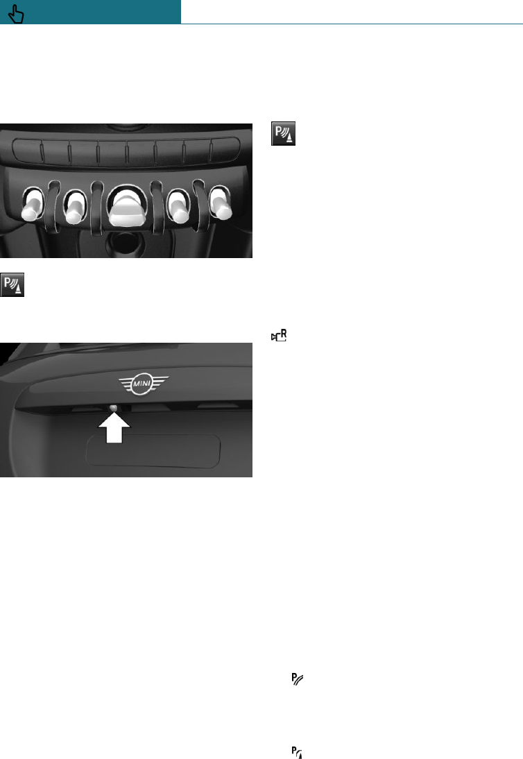
Overview
Depending on the equipment installed:
button in the vehicle
Park Assistant button
Camera
The lens of the camera is located in the han-
dle strip of the tailgate.
Dirt can impair the quality of the image.
Clean the camera lens if required.
Switching on/off
Switching on automatically
The system is automatically switched on if
selector lever position R is engaged while
the engine is running.
Automatic switching off when moving
forwards
The system switches off when a certain dis-
tance or speed is exceeded.
Switch the system back on if necessary.
Depending on the equipment installed:
switching on/off manually
Press the Park Assistant button.
–On: the LED is illuminated.
–Off: the LED is extinguished.
The parking assistance functions are shown
on the Control Display.
Changing the view on the on-board
monitor
If the rear-view camera view is not dis-
played, change the view via the on-board
monitor:
"Rear view camera"
The image from the rearview camera is
shown.
Display on the Control Display
Operating requirements
–The rearview camera is switched on.
–The tailgate is completely closed.
–Keep the detection area of the camera
clear. Projecting loads or carrier systems
and trailers that are not connected to a
trailer socket can lead to malfunctions.
Activating assistance functions
A number of assistance functions can be ac-
tive simultaneously.
The zoom function for towing a trailer can
only be activated individually.
–Parking aid lines
"Parking guidance lines"
Driving path lines and turning circle
lines are shown.
–Obstacle marking
"Obstacle marking"
Seite 188
CONTROLS Driving comfort
188 Online Edition for Part no. 01402988211 - II/18
Draft
from BA-76
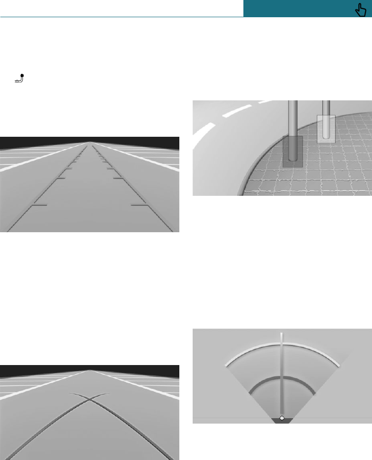
Depending on the equipment installed,
obstacles are highlighted.
–Trailer tow hitch
"Towbar zoom"
A zoomed-in image of the trailer tow
hitch is displayed.
Driving path lines
The driving path lines can appear in the im-
age from the rearview camera.
The driving path lines help to estimate the
required space when parking and manoeu-
vring on a level road surface.
The driving path lines are dependent on the
current steering angle and are continuously
adapted to steering wheel movements.
Turning circle lines
The turning circle lines can be shown in the
image from the rearview camera.
The turning circle lines show the course of
the smallest possible turning circle on a
level road surface.
Once the steering wheel has been turned
beyond a certain angle, only one turning cir-
cle line is displayed.
Obstacle marking
Depending on the equipment installed, ob-
stacle markings can be shown in the image
from the rear-view camera.
The colour incrementation corresponds to
the markings of Park Distance Control PDC.
Zoom to trailer tow hitch
To assist with connecting up a trailer, the
picture area around the trailer tow hitch can
be zoomed.
Two static circle segments show the dis-
tance between the trailer and the trailer tow
hitch.
A docking line which is dependent on the
steering angle assists you in lining up the
trailer tow hitch with the trailer.
The zoom function can be enabled when the
camera is switched on.
Seite 189
Driving comfort CONTROLS
189
Online Edition for Part no. 01402988211 - II/18
Draft
from BA-76
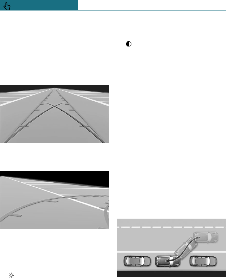
When zooming in, remember that the view
might no longer show certain obstacles.
Parking with the help of driving
path and turning circle lines
1. Position the vehicle so that the turning
circle lines are within the boundaries of
the parking space.
2. Turn the steering wheel so that the driv-
ing path line covers the corresponding
turning circle line.
Display settings
Brightness
With rearview camera switched on:
1. Select the symbol.
2. Turn the Controller until the desired set-
ting is reached and press the Controller.
Contrast
With rearview camera switched on:
1. Select the symbol.
2. Turn the Controller until the desired set-
ting is reached and press the Controller.
System limits
Detection of objects
Very low obstacles or higher, protruding ob-
jects such as ledges may not be detected by
the system.
Depending on the equipment installed,
some assistance functions also consider
Park Distance Control PDC data.
Observe the notes in the chapter on Park
Distance Control PDC.
The objects shown on the Control Display
may be closer than they appear. The dis-
tance to objects is therefore not estimated
on the display.
Park Assistant
Principle
The system supports you when parking par-
allel to the road.
General
Operation of the Park Assistant is divided
into three steps:
Seite 190
CONTROLS Driving comfort
190 Online Edition for Part no. 01402988211 - II/18
Draft
from BA-76
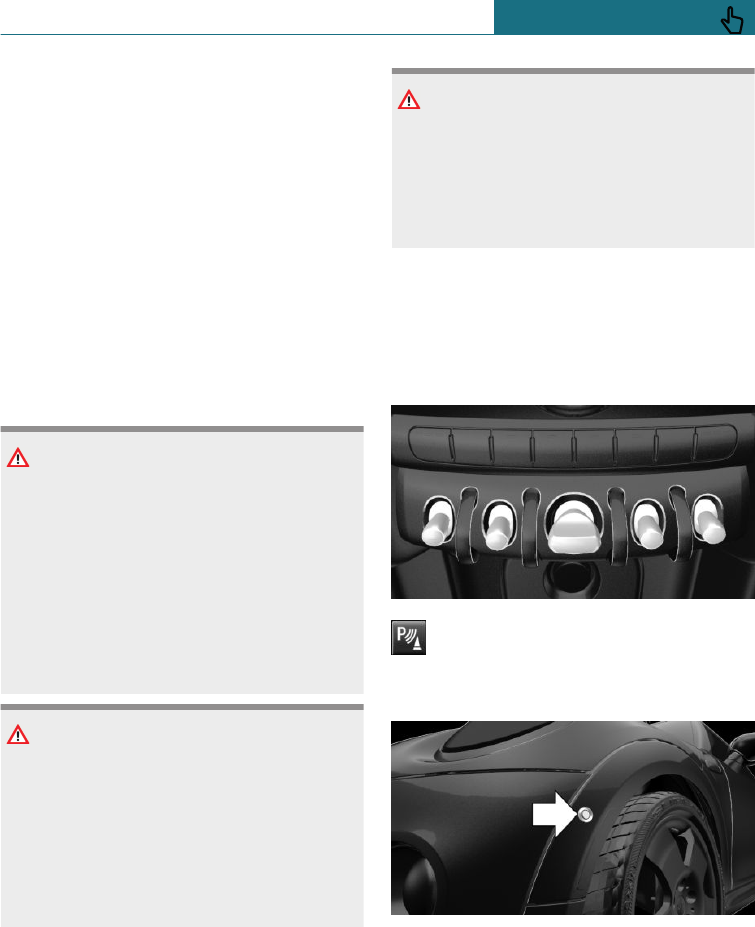
–Switching on and activating.
–Parking space search.
–Parking.
Ultrasonic sensors measure parking spaces
on both sides of the vehicle.
The Park Assistant calculates the ideal park-
ing line and takes over steering during the
process of parking.
The status of the system and the actions re-
quired are shown on the Control Display.
The Park Assistant incorporates Park Dis-
tance Control, PDC.
Safety notes
WARNING
The system does not relieve you of your
personal responsibility to assess the traffic
situation correctly. Due to system limita-
tions, it cannot respond independently and
appropriately in all traffic conditions.
There is a danger of accidents. Adapt your
driving style to the traffic conditions. Ob-
serve the traffic situation and intervene
actively if the situation warrants it.
WARNING
When the trailer tow hitch is used, the
Park Assistant could cause damage if its
sensors are obstructed. There is a danger
of accidents or damage to property. Do not
use the Park Assistant when towing a
trailer or using the trailer tow hitch, for
example with a bicycle carrier.
NOTE
The Park Assistant may steer across kerb
or up onto kerbs. There is a danger of dam-
age to property. Observe the traffic situa-
tion and intervene actively if the situation
warrants it.
In addition, the safety notes for Park Dis-
tance Control PDC apply.
Overview
Button in the vehicle
Park Assistant button
Ultrasonic sensors
The ultrasonic sensors to measure parking
spaces are located on the wheel trim.
Seite 191
Driving comfort CONTROLS
191
Online Edition for Part no. 01402988211 - II/18
Draft
from BA-76
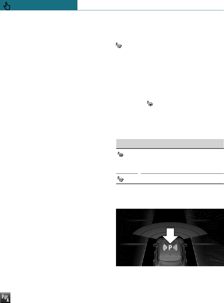
Operating requirements
Ultrasonic sensors
To ensure full functional capability:
–Do not cover the sensors, for example
with stickers.
–Keep the sensors clean and unobstruc-
ted.
For measuring parking spaces
–The vehicle must be driving forwards in
a straight line at speeds up to approxi-
mately 35 km/h, approximately 22 mph.
–Maximum distance to the row of parked
vehicles: 1.5 m, approximately 5 ft.
Suitable parking space
–Gap behind an object that is at least
1.5 m, approximately 5 ft long.
–Gap between two objects, each at least
1.5 m, approximately 5 ft long.
–Minimum length of gap between two ob-
jects: own vehicle length plus approxi-
mately 1.0 m, approximately 3.3 ft.
–Minimum depth: approximately 1.5 m,
approximately 5 ft.
For parking
–Doors and tailgate are closed.
–The parking brake is released.
–You must indicate accordingly when
parking into parking spaces on the driv-
er's side.
Switching on and activating
Switching on with the button
Press the Park Assistant button.
The LED is illuminated.
It is possible to display the current status of
the parking space search on the Control Dis-
play.
Park Assistant is automatically activa-
ted.
Switching on with reverse gear
Engage reverse gear.
It is possible to display the current status of
the parking space search on the Control Dis-
play.
To activate: "Park Assist"
Display on the Control Display
System is activated/deactivated
Symbol Meaning
Grey: system not available.
White: system available but not
activated.
System is activated.
Parking space search and status of the
system
–Symbol P on the vehicle diagram: Park
Assistant is activated and the parking
space search is active.
–Suitable parking spaces are shown on
the Control Display on the edge of the
roadway next to the vehicle symbol.
When Park Assistant is active, the suit-
Seite 192
CONTROLS Driving comfort
192 Online Edition for Part no. 01402988211 - II/18
Draft
from BA-76
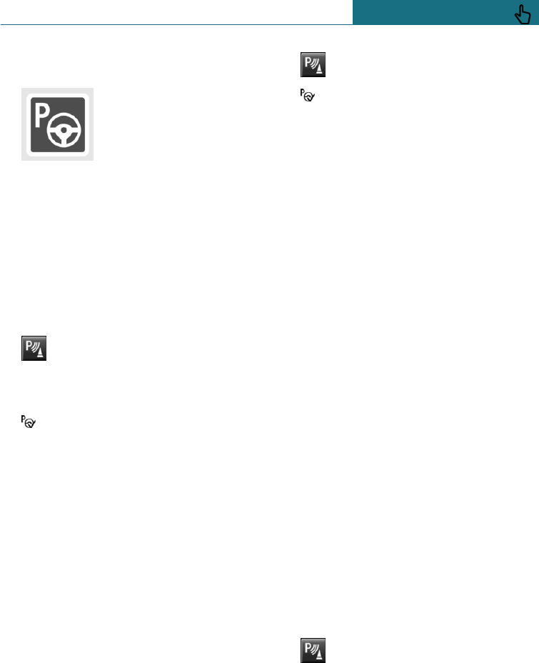
able parking spaces are highlighted in
colour.
–Parking process active.
Steering has been taken
over.
–The parking space search is active
whenever the vehicle is driving for-
wards at low speed, even with deactiva-
ted system. If the system is deactivated,
the displays on the Control Display are
shown grey.
Parking with the Park Assistant
Driving into a parking space
1. Press the Park Assistant button or
engage reverse gear to switch on the
Park Assistant, see page 192. Activate
Park Assistant if necessary.
Park Assistant is activated.
2. Drive past the line of parked vehicles at
a speed up to approximately 35 km/h,
approximately 22 mph and at a distance
of maximum 1.5 m, approximately 5 ft.
The status of the parking space search
and possible parking spaces are shown
on the display, see page 192.
3. Follow the instructions on the display.
To achieve an optimum parking posi-
tion, wait for the automatic steering
process after changing gear at standstill.
The end of the parking process is dis-
played on the display.
4. Straighten up the parking position, if ap-
plicable.
Cancelling manually
You can cancel the Park Assistant at any
time:
–Press the Park Assistant button.
– "Park Assist"
Cancelling automatically
The system automatically cancels in the
following situations:
–If the driver grasps the steering wheel
or steers the vehicle.
–When selecting gear, which does not
correspond to the information on the
display.
–At speeds over approximately 10 km/h,
approximately 6 mph.
–On snow-covered or slippery road surfa-
ces, if necessary.
–When a maximum number of parking at-
tempts or parking time is exceeded.
–If the Park Distance Control PDC shows
gaps that are too small.
–When toggling in other functions of the
radio.
A Check Control message is shown.
Resuming
You can continue a cancelled parking proc-
ess, if applicable.
To do this, reactivate the Park Assistant,
see page 192, and follow the instructions on
the display.
Switching off
The system can be switched off as follows:
–Press the Park Assistant button.
–Switch the ignition off.
Seite 193
Driving comfort CONTROLS
193
Online Edition for Part no. 01402988211 - II/18
Draft
from BA-76

System limits
Safety note
WARNING
The system may not respond at all, or may
respond too late, incorrectly, or without
justification due to limits of the system.
There is a danger of accidents or damage
to property. Observe the information on
the system limits and intervene actively if
necessary.
No parking assistance
The Park Assistant does not provide assis-
tance in the following situations:
–On sharp bends.
–When towing a trailer.
Functional limitations
The system may have limited functionality
in the following situations, for example:
–On uneven road surfaces, for example
gravel roads.
–On slippery ground.
–If leaves have collected or snow has drif-
ted or been piled up in the parking
space.
–If the emergency wheel has been fitted.
–If there are ditches or sudden drops,
for example a quayside.
Limits of the ultrasound measurement
Detection of objects might not be possible if
the limits of the physical ultrasound meas-
urement are exceeded, such as for instance
at the following times:
–Small children and animals.
–Persons wearing certain types of cloth-
ing, for example a coat.
–External interference of the ultrasound,
for example by passing vehicles or loud
machines.
–Sensors which are dirty, iced-up, dam-
aged or incorrectly adjusted.
–When a projecting load is being trans-
ported.
–Certain weather conditions, for example
high humidity, wet conditions, snowfall,
extreme heat or strong wind.
–The trailer drawbars and tow hitches of
other vehicles.
–Thin or wedge-shaped objects.
–Moving objects.
–Higher protruding objects, for example
projecting walls or loads.
–Objects with corners and sharp edges.
–Objects with fine surfaces or structures,
for example fences.
–Objects with porous surfaces.
–Low objects already indicated, such as
kerbs, may enter the sensors' blind areas
before or after a continuous tone is
given.
–In some cases, parking spaces may be
detected that are not suitable.
Tyre size
The park position may vary, depending on
the tyre size.
Malfunction
A Check Control message is shown.
The Park Assistant has failed. Have the sys-
tem checked by a Service Partner of the
manufacturer or another qualified Service
Partner or a specialist workshop.
Seite 194
CONTROLS Driving comfort
194 Online Edition for Part no. 01402988211 - II/18
Draft
from BA-76
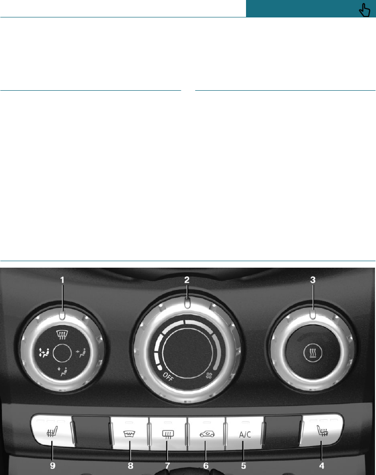
Air conditioning
Vehicle equipment
This chapter describes all standard, country-
specific and special equipment available for
the model series. Therefore equipment
which is not installed in your vehicle, for
example on account of the optional equip-
ment selected or the country specification,
may also be described here. This also ap-
plies to safety-relevant functions and sys-
tems. Comply with the relevant laws and
regulations when using the corresponding
functions and systems.
Interior air quality
An emissions-tested interior and the instal-
lation of microfilters and a climate-control
system with functions for controlling the
temperature, air flow and air recirculation
have improved air quality inside the vehicle.
In addition there are other functions which
depend on the vehicle's equipment, for ex-
ample microfilter/activated charcoal filter,
automatic air conditioning and independent
ventilation.
Air conditioning system
1Air distribution
2Air flow
3Temperature
4Seat heating, right 80
5Cooling function
6Recirculated-air mode
7Rear window heating
8Windscreen heating
Seite 195
Air conditioning CONTROLS
195
Online Edition for Part no. 01402988211 - II/18
Draft
from BA-76
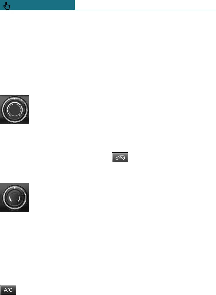
9Seat heating, left 80
Air conditioning functions in detail
Switches system on/off
Switching on
Set desired air flow.
Switching off
Turn the wheel for air flow to
the left as far as it will go.
Temperature
Principle
The system heats or cools, depending on the
set temperature.
To adjust
Turn the wheel to select the
desired temperature.
Cooling function
Principle
Interior air is cooled and dried, then rehea-
ted to suit the temperature setting.
The interior can only be cooled when the
engine is running.
Switching on/off
Press the button.
The LED is illuminated when the
cooling function is switched on.
Depending on weather conditions, the
windscreen may mist over for a short time
when the engine is started.
Condensation, see page 223, develops in
the air conditioning and exits underneath
the vehicle.
Recirculated-air mode
Principle
If the air outside the vehicle has an unpleas-
ant odour or contains pollutants, the supply
to the interior of the vehicle can be shut off.
The air inside the vehicle is then recircula-
ted.
Operation
Press the button repeatedly to call
up an operating mode:
–LED off: ambient air is constantly enter-
ing the car.
–LED on, recirculated-air mode: the ambi-
ent air supply is permanently shut off.
The recirculated-air mode automatically
switches off after a given time depending
on the outside temperature, to avoid con-
densation.
Continuous recirculated-air mode deterio-
rates the air quality in the interior and con-
densation on the windows increases.
In the event of condensation, switch off the
recirculated-air mode and increase the air
flow if necessary.
To adjust the air flow manually
Principle
The air flow for air conditioning can be set
manually.
Seite 196
CONTROLS Air conditioning
196 Online Edition for Part no. 01402988211 - II/18
Draft
from BA-76
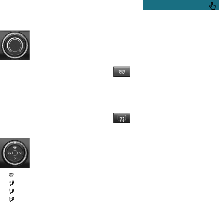
Operation
Turn the wheel to set the de-
sired air flow.
The heating or cooling power
is more effective the greater
the air flow.
The air flow of the air conditioning system
is reduced as necessary to save the battery.
To adjust the air distribution manually
Principle
The air distribution for air conditioning can
be set manually.
Operation
Turn the wheel to select the
desired programme or the de-
sired intermediate setting.
– Windows.
– Upper body area.
– Footwell.
– Windows, upper body area and foot-
well.
Defrosting windows and removing
condensation
Perform the following settings to defrost
the windows and remove condensation:
–Direct the air distribution onto the win-
dows.
–Increase the air flow.
–Increase the temperature.
–Switch on the cooling function if nee-
ded.
Windscreen heating
Press the button. The LED is illumi-
nated.
The windscreen heating is switched off au-
tomatically after a certain period of time.
Rear window heating
Press the button. The LED is illumi-
nated.
The rear window heating is switched off au-
tomatically after a certain period of time.
Press and hold the button for more than
3 seconds for continuous activation. Press
the button again to deactivate.
The rear window heating can only be activa-
ted continuously at an outside temperature
below approximately 5 ℃/41 ℉.
If GREEN drive mode is activated, the heat-
ing power is reduced.
Microfilter
In outside and recirculated-air mode, the
microfilter filters dust and pollen from the
air.
Have this filter replaced during mainte-
nance, see page 302, of the vehicle.
Seite 197
Air conditioning CONTROLS
197
Online Edition for Part no. 01402988211 - II/18
Draft
from BA-76
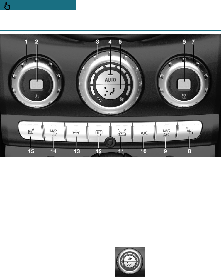
Automatic air conditioning
1Temperature, left
2Display
3Air flow, AUTO intensity
4AUTO program
5To adjust the air distribution manually
6Display
7Temperature, right
8Seat heating, right 80
9Maximum cooling effect
10 Cooling function
11 Recirculated-air mode
12 Rear window heating
13 Windscreen heating
14 Defrosting windows and removing con-
densation
15 Seat heating, left 80
Air conditioning functions in detail
Switches system on/off
Switching on
Set desired air flow.
Switching off
Turn wheel for air flow to the
left, until the control shuts
down.
Temperature
Principle
The automatic air conditioning adjusts to
the set temperature as quickly as possible,
Seite 198
CONTROLS Air conditioning
198 Online Edition for Part no. 01402988211 - II/18
Draft
from BA-76
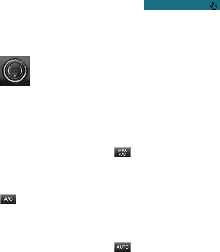
using maximum cooling or heating power if
necessary. The temperature is then main-
tained.
To adjust
Turn the wheel to select the
desired temperature.
Avoid switching between different tempera-
ture settings in rapid succession. The auto-
matic air conditioning may not have suffi-
cient time to establish the temperature
selected.
Cooling function
Principle
Interior air is cooled and dried, then rehea-
ted to suit the temperature setting.
The interior can only be cooled when the
engine is running.
Switching on/off
Press the button.
The LED is illuminated when the
cooling function is switched on.
Depending on weather conditions, the
windscreen may mist over for a short time
when the engine is started.
The cooling function is switched on auto-
matically in the AUTO program.
When the automatic air conditioning is in
operation, condensation, see page 223, de-
velops which exits underneath the vehicle.
Maximum cooling effect
Principle
System is set to the lowest temperature,
maximum air flow and recirculated-air
mode.
General
The function is available with an outside
temperature above approximately 0 ℃/32 ℉
and with the engine running.
The air flows from the side nozzles for the
upper body area. Therefore open the side
nozzles.
The air flow can be adapted when the pro-
gramme is active.
Switching on/off
Press the button.
The LED is illuminated when the
system is switched on.
System is set to lowest temperature, opti-
mum air flow and recirculated-air mode.
AUTO program
Principle
The air flow, air distribution and tempera-
ture are automatically regulated.
Switching on/off
Press the button.
The LED is illuminated when the
AUTO program is switched on.
Depending on the selected temperature,
AUTO intensity and external influences, the
air is directed towards the windscreen, side
windows and upper body, and into the foot-
well.
The following are switched on automatically
in the AUTO programme:
Seite 199
Air conditioning CONTROLS
199
Online Edition for Part no. 01402988211 - II/18
Draft
from BA-76
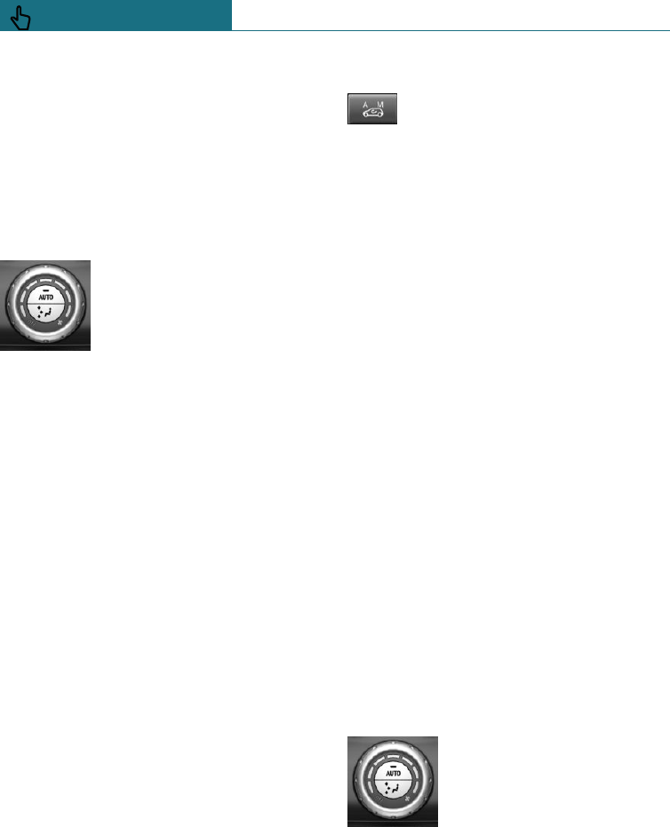
–The cooling function, see page 199.
To switch off programme: press the button
again or manually adjust the air distribu-
tion.
Intensity
When AUTO program is switched on, auto-
matic control of the intensity can be
changed.
Turn the wheel to select the
desired intensity from gentle
to intensive.
The selected intensity is displayed by the
position of an illuminated LED segment.
Automatic air recirculation control,
AUC/recirculated-air mode
Principle
Automatic air recirculation control AUC de-
tects pollutants in the outside air. The sup-
ply of outside air is shut off and the interior
air is recirculated.
General
When the system is activated, a sensor de-
tects pollutants in the outside air and con-
trols the shut-off automatically.
When the system is deactivated, outside air
flows into the interior continuously.
Continuous recirculated-air mode deterio-
rates the air quality in the interior and con-
densation on the windows increases.
If the air outside the vehicle has an unpleas-
ant odour or contains pollutants, the supply
to the interior of the vehicle can be shut off.
The air inside the vehicle is then recircula-
ted.
Switching on/off
Press the button repeatedly to call
up an operating mode:
–LEDs off: ambient air is constantly en-
tering the car.
–Left-hand LED on, AUC mode: a sensor
detects pollutants in the outside air and
shuts off the supply automatically.
–Right-hand LED on, recirculated-air
mode: the ambient air supply is perma-
nently shut off.
The recirculated-air mode automatically
switches off after a given time depending
on the outside temperature, to avoid con-
densation.
If there is condensation, switch off the re-
circulated air mode and press the AUTO
button. Ensure that air can flow towards the
windscreen.
To adjust the air flow manually
Principle
The air flow for air conditioning can be set
manually.
General
To be able to adjust the air flow manually,
first switch off the AUTO program.
Operation
Turn the wheel to set the de-
sired air flow.
Manually set air flow is displayed by illumi-
nated LED segments.
In order to protect the battery the air flow
rate of the automatic air conditioning is re-
duced, if necessary.
Seite 200
CONTROLS Air conditioning
200 Online Edition for Part no. 01402988211 - II/18
Draft
from BA-76