ALPS ALPINE 9ZUA153 Car Audio User Manual 05 Short Term Confidential 2
Alpine Electronics Inc Car Audio 05 Short Term Confidential 2
Contents
- 1. 05 (Short-Term Confidential) User Manual_1
- 2. 05 (Short-Term Confidential) User Manual_2
05 (Short-Term Confidential) User Manual_2
To adjust the air distribution manually
Principle
The air distribution for air conditioning can
be set manually.
Operation
Press the button repeatedly to se-
lect a programme:
–Windows, upper body area and footwell.
–Upper body area and footwell.
–Footwell.
–Windows and footwell.
–Windows.
–Windows and upper body area.
–Upper body area.
Defrosting windows and removing
condensation
Principle
Ice and condensation are quickly removed
from the windscreen and the front side win-
dows.
Switching on/off
Press the button.
The LED is illuminated when the
system is switched on.
Ice and condensation are quickly removed
from the windscreen and the front side win-
dows.
The air flow can be adapted when the pro-
gramme is active.
If there is condensation, switch on the cool-
ing function too.
Windscreen heating
Press the button. The LED is illumi-
nated.
The windscreen heating is switched off au-
tomatically after a certain period of time.
Rear window heating
Press the button. The LED is illumi-
nated.
The rear window heating is switched off au-
tomatically after a certain period of time.
Press and hold the button for more than
3 seconds for continuous activation. Press
the button again to deactivate.
The rear window heating can only be activa-
ted continuously at an outside temperature
below approximately 5 ℃/41 ℉.
If GREEN drive mode is activated, the heat-
ing power is reduced.
Microfilter/activated carbon filter
In outside and recirculated-air mode, the
microfilter/activated carbon filter filters
dust, pollen and harmful gases from the air.
Have this filter replaced during mainte-
nance, see page 302, of the vehicle.
Ventilation
Setting
The direction of the air flows can be set in-
dividually:
–Direct ventilation:
The air flow is pointing directly at the
person. The air flow provides noticeable
heating or cooling depending on the set
temperature.
–Indirect ventilation:
When side nozzles are fully or partially
closed, air is indirectly channelled into
the interior.
Seite 201
Air conditioning CONTROLS
201
Online Edition for Part no. 01402988211 - II/18
Draft
from BA-76
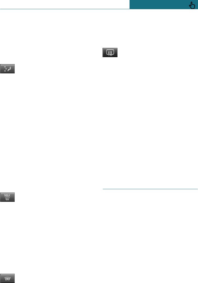
Ventilation at front
–Turn button to open and close the air
outlets steplessly.
–Turn the air outlets to change the direc-
tion of air flow, arrows.
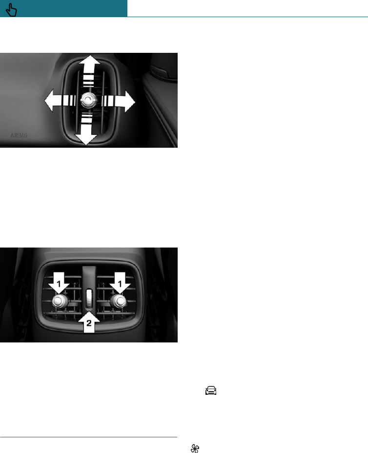
Ventilation in rear passenger
compartment
–Lever for changing the air flow direc-
tion, arrows 1.
–Knurled wheel for steplessly opening
and closing the side nozzles, arrow 2.
Independent ventilation
Principle
The independent ventilation system venti-
lates the passenger compartment and low-
ers its temperature where required.
General
The independent ventilation can be
switched on and off via two preselected
switch-on times or directly. The system re-
mains switched on for 30 minutes.
The independent ventilation is operated us-
ing the on-board monitor.
Operating requirements
–Direct operation: vehicle is in radio
ready state.
–Direct operation or preselected switch-
on time: does not depend on the outside
temperature.
–Battery is sufficiently charged.
When activated, the independent venti-
lation uses power from the vehicle bat-
tery. As a result, the maximum activa-
tion time is restricted to protect the
battery. After the engine is started or af-
ter driving a short distance, the system
will be available again.
–Ensure that the date and time are set
correctly in the vehicle.
–Open the ventilation vents to allow the
air to enter the passenger compartment.
Switching on/off directly
Using the on-board monitor:
1. "My MINI"
2. "Vehicle settings"
3. If necessary, "Climate comfort"
4. "Activate auxiliary ventilation now"
symbol on automatic air conditioning
flashes when system is switched on.
Seite 202
CONTROLS Air conditioning
202 Online Edition for Part no. 01402988211 - II/18
Draft
from BA-76

Preselecting the switch-on time
Using the on-board monitor:
1. "My MINI"
2. "Vehicle settings"
3. If necessary, "Climate comfort"
4. "Auxiliary ventilation"
5. Select the required switch-on time.
6. Set desired time.
Activating the switch-on time
Using the on-board monitor:
1. "My MINI"
2. "Vehicle settings"
3. If necessary, "Climate comfort"
4. "For start time at:"
Activate the required switch-on time.
Symbol on the automatic air condition-
ing system is illuminated when the switch-
on time is active.
Symbol on the automatic air condition-
ing system flashes when the system has cut
in.
The system switches on within the next
24 hours only. Afterwards, it must be reacti-
vated.
Seite 203
Air conditioning CONTROLS
203
Online Edition for Part no. 01402988211 - II/18
Draft
from BA-76
Interior equipment
Vehicle equipment
This chapter describes all standard, country-
specific and special equipment available for
the model series. Therefore equipment
which is not installed in your vehicle, for
example on account of the optional equip-
ment selected or the country specification,
may also be described here. This also ap-
plies to safety-relevant functions and sys-
tems. Comply with the relevant laws and
regulations when using the corresponding
functions and systems.
Sun visor
Glare protection
To provide protection against glaring light,
fold the sun visor downwards or swivel to
the side.
Vanity mirror
A vanity mirror is situated in the sun visor
behind a cover.
The mirror light switches on when the
cover is opened.
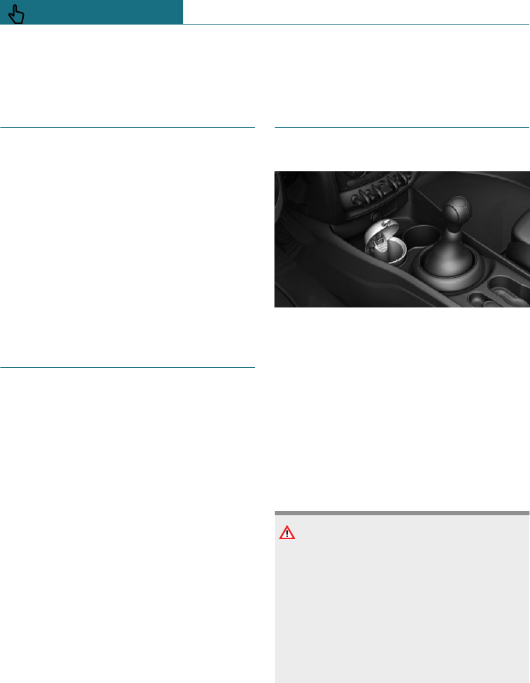
Ashtray/lighter
Overview
The ash tray is in one of the front cuphold-
ers, the cigarette lighter above it in the cen-
tre console.
Ashtrays
To empty the ash tray, take the insert out of
the cupholder.
Lighter
Safety notes
WARNING
Contact with the hot heating element or
the hot fitting of the lighter can cause
burns. Flammable materials can catch fire
if the lighter falls down or is held against
corresponding objects. There is a danger
of fire and injury. Take hold of the lighter
by its handle. Ensure that children do not
use the lighter as there is a risk of burns.
Seite 204
CONTROLS Interior equipment
204 Online Edition for Part no. 01402988211 - II/18
Draft
from BA-76

NOTE
If metallic objects fall into the socket, they
can cause a short circuit. There is a danger
of damage to property. After using the
socket, put the lighter or socket cover
back on.
Operation
Press in the cigarette lighter.
The cigarette lighter can be
removed when it pops back
out.
Power sockets
Principle
The cigarette lighter socket can be used as
a socket for electrical devices when the en-
gine is running or the ignition is switched
on.
General
The total load of all sockets must not exceed
140 watts at 12 volts.
To avoid damage to the socket, do not insert
an incompatible plug.
Safety notes
WARNING
Devices and cables, for example portable
navigation devices, that are located in the
deployment range of the airbags may im-
pede airbag deployment or be flung around
the vehicle interior when the airbag is de-
ployed. There is a danger of injury. Make
sure that devices and cables are not in the
deployment range of the airbags.
NOTE
Battery chargers for the vehicle battery
can operate with high voltages and high
currents, which can overload or damage
the 12-volt on-board network. There is a
danger of damage to property. Only con-
nect battery chargers for the vehicle bat-
tery to the jump-starting connections in
the engine compartment.
NOTE
If metallic objects fall into the socket, they
can cause a short circuit. There is a danger
of damage to property. After using the
socket, put the lighter or socket cover
back on.
In the front centre console
Remove the cover or lighter.
Seite 205
Interior equipment CONTROLS
205
Online Edition for Part no. 01402988211 - II/18
Draft
from BA-76
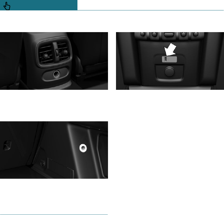
In the rear centre console
Remove the cover.
Inside the boot
Socket is on the right in the boot.
USB interface
Principle
Mobile devices with a USB port can be con-
nected to the USB interface.
General
Comply with the notes on connecting mo-
bile devices to the USB interface in the
chapter on USB connections, see page 47.
In the centre console
The USB interface is located in the front in
the centre console.
Seite 206
CONTROLS Interior equipment
206 Online Edition for Part no. 01402988211 - II/18
Draft
from BA-76
Storage compartments
Vehicle equipment
This chapter describes all standard, country-
specific and special equipment available for
the model series. Therefore equipment
which is not installed in your vehicle, for
example on account of the optional equip-
ment selected or the country specification,
may also be described here. This also ap-
plies to safety-relevant functions and sys-
tems. Comply with the relevant laws and
regulations when using the corresponding
functions and systems.
Safety notes
WARNING
Loose objects or devices connected by a
cable to the vehicle, for example mobile
telephones, can be thrown through the in-
terior during the journey, for example in
an accident or during braking and evasive
manoeuvres. There is a danger of injury.
Ensure that loose objects or devices con-
nected by cable to the vehicle are secured
in place in the interior.
NOTE
Anti-slip mats can damage the dashboard.
There is a danger of damage to property.
Do not use anti-slip mats.
Overview
The following storage facilities are located
in the interior:
–Glove box on the passenger side.
–Storage compartment under driver's
seat.
–Compartments in the doors.
–Storage compartment in the centre arm-
rest.
–Storage compartment, in front of cu-
pholders.
–Coat hooks
–Storage compartments in boot.
–Charging tray the centre console.
–Pockets on the back rests of the front
seats.
Glove box
Safety note
WARNING
The glove box projects into the interior
when it is opened. Objects in the glove box
can be thrown into the interior during the
journey, for example in an accident or dur-
ing braking and evasive manoeuvres.
There is a danger of injury. Immediately
close the glove box after using it.
Seite 207
Storage compartments CONTROLS
207
Online Edition for Part no. 01402988211 - II/18
Draft
from BA-76
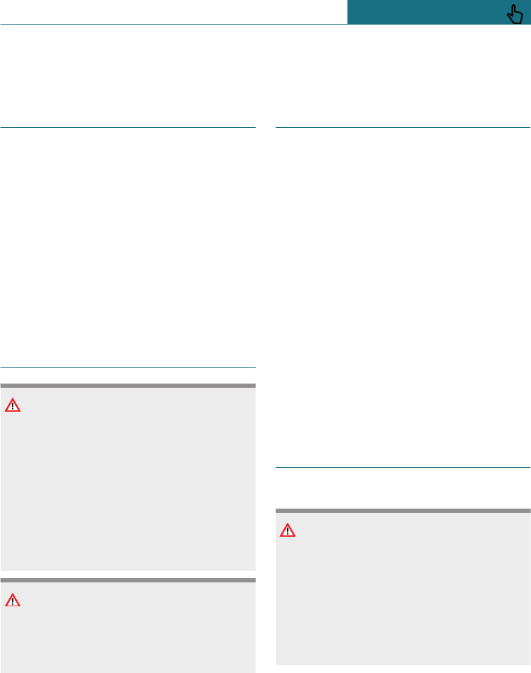
Opening
Pull the handle.
The lighting in the glove box comes on.
Closing
Fold the lid up.
Driver's seat
There is a storage compartment under the
driver's seat.
Pockets in the doors
WARNING
Fragile objects, for example glass bottles
or glasses, can break in the event of an ac-
cident. Shards can spread throughout the
interior. There is a danger of injury or
damage to property. Do not use any fragile
objects while driving. Only stow fragile
objects in closed storage compartments.
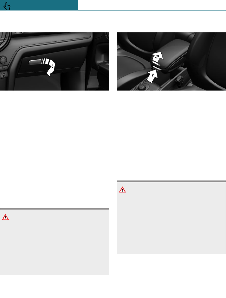
Centre armrest
General
There is a storage compartment in the cen-
tre armrest.
Opening
Press the button, arrow 1, and open the cen-
tre armrest upwards, arrow 2.
Set the incline
Centre armrest can be adjusted to several
different angles.
Cupholder
Safety note
WARNING
Unsuitable containers in the cupholder
and hot drinks can damage the cupholders
and increase the risk of injury in an acci-
dent. There is a danger of injury or damage
to property. Use lightweight, lockable con-
tainers that are shatterproof. Do not trans-
port hot drinks. Do not force objects into
the cupholder.
Seite 208
CONTROLS Storage compartments
208 Online Edition for Part no. 01402988211 - II/18
Draft
from BA-76
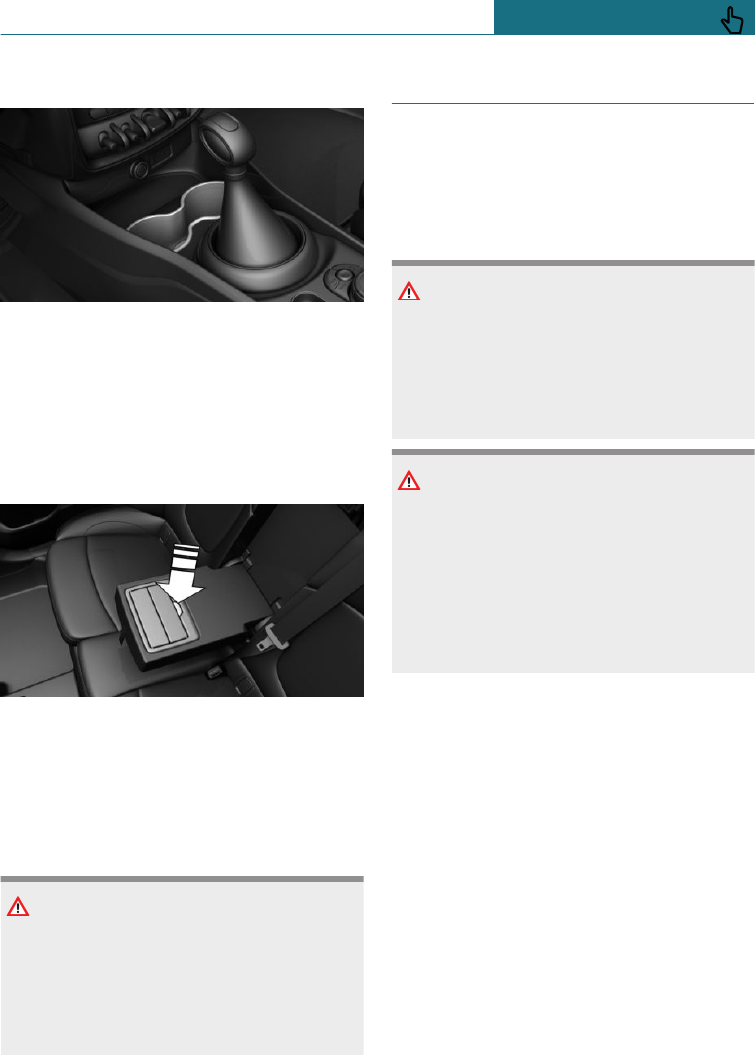
Front
In the centre console.
Rear
General
The cupholder is located in the centre arm-
rest.
Pull centre armrest forward with the loop.
To open: press the button.
To close: push both covers back in one after
the other.
Safety note
NOTE
If the cupholder is open, the centre arm-
rest cannot be folded back. There is a dan-
ger of damage to property. Push back the
covers before folding up the centre arm-
rest.
Coat hooks
General
The clothes hooks are located above the
rear doors.
Safety notes
WARNING
Items of clothing on the coat hooks can
impair visibility when driving. There is a
danger of accidents. Hang items of cloth-
ing from the clothes hooks so they do not
obstruct visibility when driving.
WARNING
Incorrect use of the coat hooks can pres-
ent a danger, for example if objects are
flung around in the event of braking and
evasive manoeuvres. There is a danger of
injury and damage to property. Only hang
lightweight objects, for example items of
clothing, on the coat hooks.
Seite 209
Storage compartments CONTROLS
209
Online Edition for Part no. 01402988211 - II/18
Draft
from BA-76
Boot
Vehicle equipment
This chapter describes all standard, country-
specific and special equipment available for
the model series. Therefore equipment
which is not installed in your vehicle, for
example on account of the optional equip-
ment selected or the country specification,
may also be described here. This also ap-
plies to safety-relevant functions and sys-
tems. Comply with the relevant laws and
regulations when using the corresponding
functions and systems.
Loads
Safety notes
WARNING
A high gross vehicle weight can cause the
tyres to overheat, causing internal damage
and a sudden loss of tyre inflation pres-
sure. The driving characteristics can be
negatively influenced, for example reduced
directional stability, longer braking dis-
tance and modified steering characteris-
tics. There is a danger of accidents. Com-
ply with the permitted load index of the
tyre, and do not exceed the permitted
gross vehicle weight.
WARNING
If the permitted total weight and the per-
mitted axle loads are exceeded, the opera-
tional safety of the vehicle is no longer
guaranteed. There is a danger of accidents.
Do not exceed the permitted total weight
and permitted axle loads.
WARNING
Loose objects or devices connected by a
cable to the vehicle, for example mobile
telephones, can be thrown through the in-
terior during the journey, for example in
an accident or during braking and evasive
manoeuvres. There is a danger of injury.
Ensure that loose objects or devices con-
nected by cable to the vehicle are secured
in place in the interior.
WARNING
Incorrectly stowed objects can slip or be
thrown into the interior, for example in an
accident, during braking or evasive ma-
noeuvres. Vehicle occupants could be hit
and injured. There is a danger of injury.
Stow and secure the objects and the load
correctly.
NOTE
Liquids in the boot may cause damage.
There is a danger of damage to property.
Ensure that no liquids leak out into the
boot.
Stowing and securing a transported
load
–Wrap protective material around any
sharp corners and edges on the load.
–Heavy transported loads: stow as far for-
ward and as low down as possible, ide-
ally directly behind the rear backrests.
Seite 210
CONTROLS Boot
210 Online Edition for Part no. 01402988211 - II/18
Draft
from BA-76
–Very heavy transported loads: if there
are no passengers on the back seat, in-
sert both outer seat belts into the re-
spective opposite buckles.
–Fully fold down the rear backrests if the
load is to be stowed accordingly.
–Do not stack load items above the upper
edge of the backrests.
–Use the luggage net, see page 211, to
protect the vehicle's occupants. Make
sure that objects cannot penetrate the
luggage net.
–Small and lightweight transported loads:
secure with tensioning straps or other
suitable straps.
–Larger and heavy transported loads: se-
cure with lashing straps.
Lashing eyes in the boot
With storage package: four lashing eyes are
located in the boot for securing the load.
Equipment for securing the transported
load, such as lashing straps, tensioning
straps or luggage nets, must be secured to
the lashing eyes in the boot.
Only use lower lashing eyes for securing the
transported load with the luggage net.
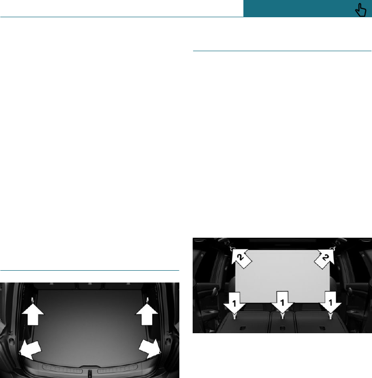
Luggage net
General
The large luggage net is attached behind
the front seats. The small luggage net is at-
tached above the second row of seats. With
the luggage net attached, the boot is separa-
ted.
Luggage net, large
1. Fold down rear backrests forwards, see
page 213.
2. Move the head restraints to the upper
position.
3. Attach the luggage net with the lower
hooks to the three eyes, arrows 1.
4. Insert both upper fastening pins of the
luggage net into the holders as far as
they will go, arrow 2, and push forwards.
Remove the luggage net by performing
these steps in reverse order.
Luggage net, small
The small luggage net can be used with the
rear backrest in upright position.
1. Remove the boot cover.
Seite 211
Boot CONTROLS
211
Online Edition for Part no. 01402988211 - II/18
Draft
from BA-76
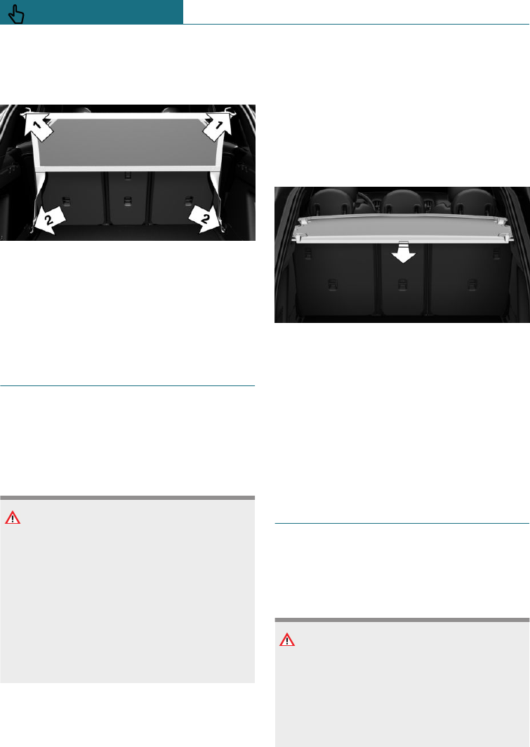
2. Insert both upper fastening pins of the
luggage net into the holders as far as
they will go, arrow 1, and push forwards.
3. Attach the luggage net with the two
lower hooks into the respective upper
lashing eyes in the boot, arrows 2.
Remove the luggage net by performing
these steps in reverse order.
Boot cover
General
The boot cover is raised when the tailgate is
opened.
Safety note
WARNING
Loose objects or devices connected by a
cable to the vehicle, for example mobile
telephones, can be thrown through the in-
terior during the journey, for example in
an accident or during braking and evasive
manoeuvres. There is a danger of injury.
Ensure that loose objects or devices con-
nected by cable to the vehicle are secured
in place in the interior.
Removing
For stowing bulky objects, the boot cover
can be removed.
1. Unhook the retaining straps on the left
and right of the tailgate.
2. Pull the boot cover on the left and right
out of the brackets.
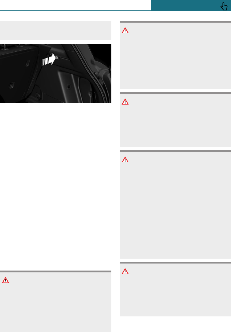
Inserting
1. Push boot cover into both side holders
horizontally forwards until you hear it
engage.
2. Attach the holding straps onto the left
and right of the tailgate.
Storage compartments in the
boot
Side storage compartment
There is a storage compartment on the left.
Bag holders
WARNING
Incorrect use of the bag holders can pres-
ent a danger, for example if objects are
flung around in the event of braking and
evasive manoeuvres. There is a danger of
injury and damage to property. Only hang
light objects, for example shopping bags,
Seite 212
CONTROLS Boot
212 Online Edition for Part no. 01402988211 - II/18
Draft
from BA-76
on the bag holders. Only transport heavy
luggage in the boot if suitably secured.
There are two bag holders in the boot.
Expanding the boot
Principle
Depending on the equipment fitted, the
boot can be enlarged as follows:
–The rear backrests can be folded down.
–The rear backrests can be placed in the
cargo position to achieve an upright
loading position.
General
The rear backrest is split 40–20–40. The
outer rear backrests can be folded down in-
dividually or the middle part separately.
The rear backrests can be folded down from
the rear.
Safety notes
WARNING
Risk of trapping when folding down the
rear backrest. There is a danger of injury
or damage to property. Before folding
down, make sure that the area of move-
ment of the rear backrest and the head re-
straint is kept clear.
WARNING
If a rear seat backrest is not locked, unse-
cured cargo can be thrown into the inte-
rior, for example in the event of an acci-
dent or during braking or avoidance
manoeuvres. There is a danger of injury.
Make sure that the rear seat backrest is
locked after it has been folded back.
WARNING
The backrest can unexpectedly move dur-
ing the journey as a result of being unin-
tentionally unlocked via the loops. There is
a danger of injury. Do not attach objects to
the loops for unlocking the rear backrests.
WARNING
If the seat adjustment or child seat instal-
lation is incorrect, the child restraint sys-
tem may have limited stability or may not
be stable at all. There is a danger of injury
or even death. Make sure the child re-
straint system is firmly positioned against
the backrest. Wherever possible, adapt the
backrest angle of all the relevant seat
backrests and adjust the seats correctly.
Make sure that the seats and their backr-
ests are correctly engaged or locked. If
possible, adjust the height of the head re-
straints, or remove them.
WARNING
Parts of the body can become trapped
when the head restraints are moving.
There is a danger of injury. When moving
the head restraint, make sure that the area
of movement is kept clear.
Seite 213
Boot CONTROLS
213
Online Edition for Part no. 01402988211 - II/18
Draft
from BA-76
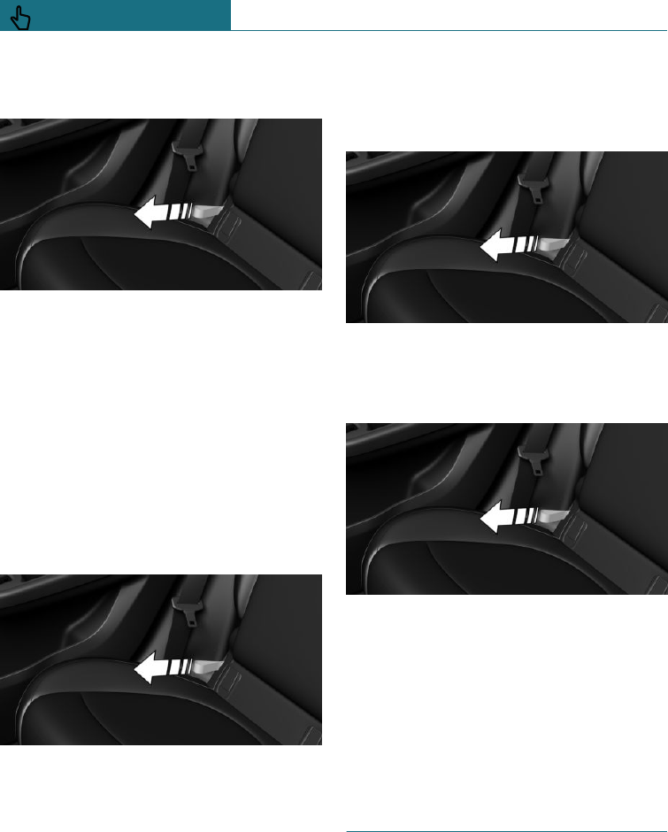
Folding rear backrest down from
the rear
Pull the loop forwards. The rear backrest
folds forwards.
Cargo position
Principle
The rear backrests can be individually ad-
justed in several stages into an upright
loading position.
To adjust
1. Pull loop.
2. Set the loading position of the rear back-
rest as required.
3. Lock the rear seat backrest into posi-
tion.
Folding back the rear backrest
Without cargo position:
1. Pull loop.
2. Fold the rear backrest back.
With cargo position:
1. Pull loop.
2. Fold the rear backrest back. The rear
backrest initially locks in place in the
loading position.
3. Pull loop once again.
4. Fold the rear backrest completely back.
5. Lock the rear seat backrest into posi-
tion.
Variable boot floor
Principle
The variable boot floor enables the boot to
be configured to suit transport require-
ments.
Seite 214
CONTROLS Boot
214 Online Edition for Part no. 01402988211 - II/18
Draft
from BA-76
General
Comply with notes on securing the load, see
page 210.
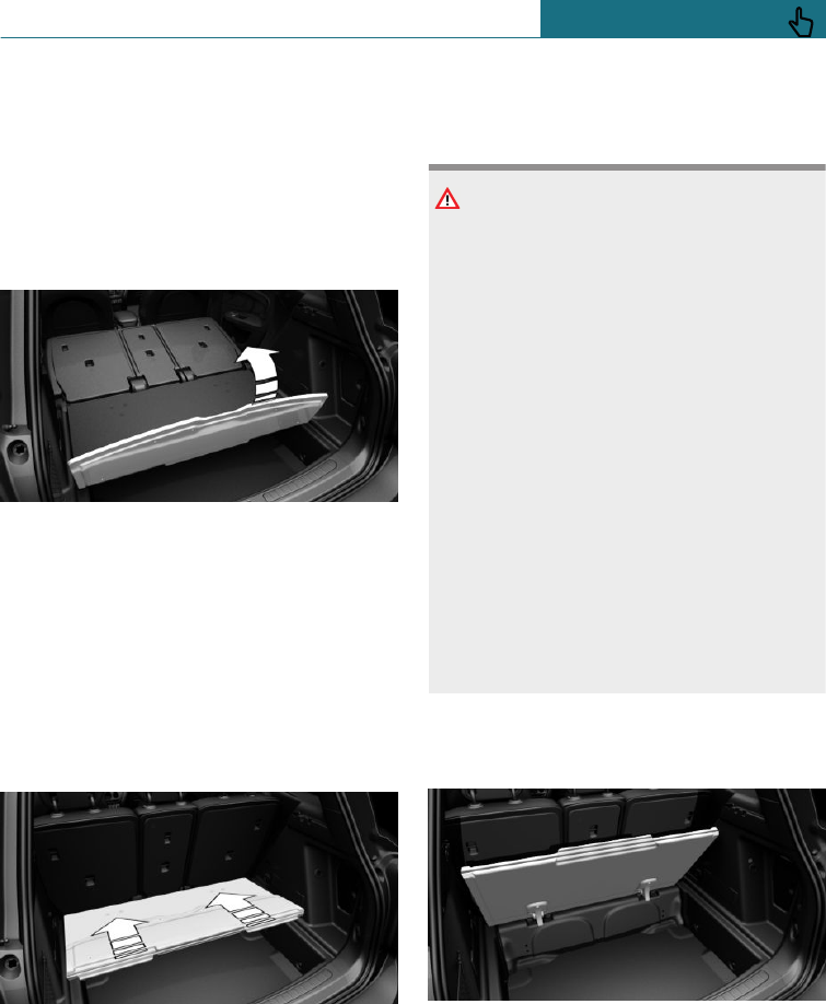
Removing boot floor
1. Fold down rear backrests, see page 213.
2. Fold up the rear part of the boot floor.
3. Grip the boot floor at rear and fold up-
wards beyond the locking point of the
upper position, see page 215.
4. Pull boot floor backwards out of the
mounts.
Inserting the boot floor
1. Press the boot floor into the mounts at a
flat angle. The boot floor must noticea-
bly engage.
2. Fold the boot floor downwards.
Folded up position
Safety note
WARNING
Incorrect use of the variable boot floor
may result in objects being flung around
in the event of braking or evasive manoeu-
vres. There is a danger of injury and dam-
age to property.
–Do not use the variable boot floor like
a partition net to separate the boot
from the vehicle interior in terms of a
partition net.
–Only use the variable boot floor panel
in the folded-up position when the
backrests are folded up and locked.
–Fold down the variable boot floor
panel before driving off.
–Always secure the load to prevent
slipping, for example with tensioning
or lashing straps and the lashing
eyes.
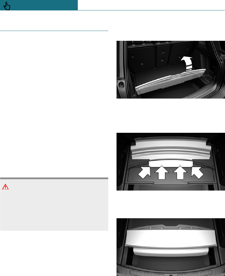
Folding up the boot floor
Fold up the rear part of the boot floor.
Fold up boot floor. The maximum boot
height is achieved.
Seite 215
Boot CONTROLS
215
Online Edition for Part no. 01402988211 - II/18
Draft
from BA-76
MINI Picnic Bench
Principle
The MINI Picnic Bench provides comforta-
ble seating on the load edge of the vehicle.
General
Only use the MINI Picnic Bench when the
vehicle is parked and the tailgate is opened.
When not in use, fold in the MINI Picnic
Bench to prevent soiling or damage.
In the case of vehicles with contactlessly
opening and closing tailgate:
If the remote control is within the sensor
range, the tailgate can be accidentally
opened or closed by an unintentional or pre-
sumed foot movement.
The sensor range extends to approximately
1.50 m, 5 ft behind the rear area.
Safety note
WARNING
Operation of the tailgate can lead to parts
of the body becoming trapped. There is a
danger of injury. When opening and clos-
ing, make sure that the area of movement
of the tailgate is kept clear.
Overview
The MINI Picnic Bench is located on the un-
derside the boot floor.
Fitting
1. Fold up the rear part of the boot floor.
2. Place the MINI Picnic Bench on the
front part of the boot floor and attach it
to the rear part of the boot floor using
the four snap fasteners.
3. Fold down the MINI Picnic Bench to-
wards the rear. The MINI Picnic Bench
is fastened with magnets.
4. Fold the rear part of the boot floor
downwards.
To remove the MINI Picnic Bench, proceed
in reverse order.
Seite 216
CONTROLS Boot
216 Online Edition for Part no. 01402988211 - II/18
Draft
from BA-76
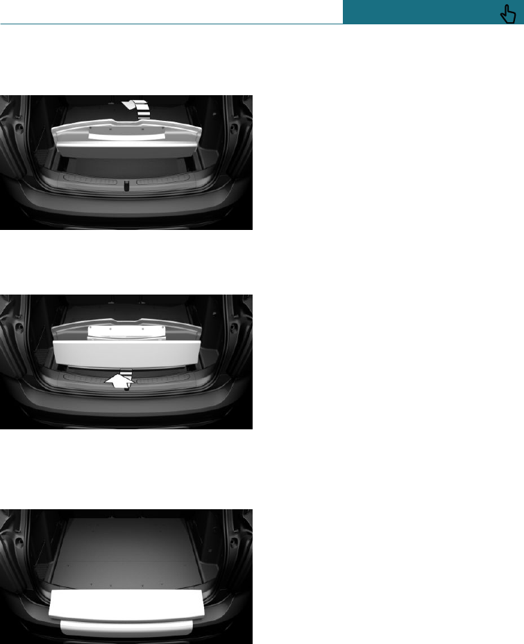
Folding down
1. Raise the rear part of the boot floor.
2. Grip the middle of the MINI Picnic
Bench and pull backwards and upwards
against the resistance of the magnets.
3. Fold the rear part of the boot floor
downwards and place the MINI Picnic
Bench over the load edge of the boot.
Place the dirt cover over the bumper.
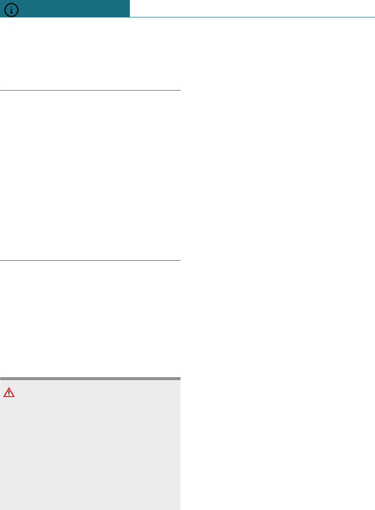
Folding up
Fold up the rear part of the boot floor.
The MINI Picnic Bench swings onto the un-
derside of the boot floor and is held in place
there by magnets.
Seite 217
Boot CONTROLS
217
Online Edition for Part no. 01402988211 - II/18
Draft
from BA-76

218
Online Edition for Part no. 01402988211 - II/18
Draft
from BA-76

DRIVING HINTS
Driving precautions .............................................................................. 220
Towing a trailer or using rear luggage rack .................................. 229
Saving fuel ............................................................................................... 236
219
Online Edition for Part no. 01402988211 - II/18
Draft
from BA-76
Driving precautions
Vehicle equipment
This chapter describes all standard, country-
specific and special equipment available for
the model series. Therefore equipment
which is not installed in your vehicle, for
example on account of the optional equip-
ment selected or the country specification,
may also be described here. This also ap-
plies to safety-relevant functions and sys-
tems. Comply with the relevant laws and
regulations when using the corresponding
functions and systems.
Running in
General
Moving parts must adapt to one another.
The following notes will help to maximise
the vehicle's lifetime and efficiency.
Do not use Launch Control, see page 122,
when running in.
Safety note
WARNING
New parts and components can cause
safety and Driver Assistance Systems to
respond with a delay. There is a danger of
accidents. After new parts have been in-
stalled, or if the vehicle is new, drive mod-
erately and intervene at an early stage if
necessary. Comply with running-in proce-
dures for the corresponding parts and
components.
Engine, gearbox and differential
Up to 2000 km, 1200 miles
Do not exceed the maximum engine revs
and speed:
–With petrol engines, 4500 rpm and
160 km/h, approximately 100 mph.
–With diesel engines, 3500 rpm and
150 km/h, approximately 93 mph.
Generally avoid kick-down and driving un-
der full load.
From 2000 km, 1200 miles onwards
Engine and road speeds can be gradually in-
creased.
Tyres
Due to the manufacturing process, new
tyres do not achieve their full road grip im-
mediately.
Drive moderately for the first 300 km, ap-
proximately 200 miles.
Brake system
Brake discs and pads only achieve their full
effectiveness after approximately 500 km,
approximately 300 miles. Drive moderately
during this running-in period.
Clutch
The clutch only begins to function optimally
at approximately 500 km, approximately
300 miles. Engage the clutch gently during
this running-in period.
After fitting new parts
The same running-in procedures should be
observed if any of the components men-
Seite 220
DRIVING HINTS Driving precautions
220 Online Edition for Part no. 01402988211 - II/18
Draft
from BA-76
tioned above have to be renewed in the
course of the vehicle's operating life.
General driving information
Closing the tailgate
Safety note
WARNING
An open tailgate projects beyond the vehi-
cle, and in the event of an accident, brak-
ing or avoidance manoeuvres, it can en-
danger vehicle occupants and other road
users, or damage the vehicle. There is also
the danger of exhaust fumes entering the
interior of the vehicle. There is a danger of
injury or damage to property. Do not drive
with the tailgate open.
Driving with the tailgate open
If there is no alternative to driving with the
tailgate open:
–Close all the windows and the Glass
Roof.
–Turn up the blower to a high setting.
–Maintain a moderate speed.
Hot exhaust system
WARNING
During driving, high temperatures can oc-
cur under the body, for example because
of the exhaust system. If flammable mate-
rials, for example leaves or grass, come
into contact with hot parts of the exhaust
system, these materials can catch fire.
There is a danger of injury or damage to
property. Never remove the heat shields
fitted here, or apply underseal to them.
Make sure that when driving, idling or
parking, no flammable materials can come
into contact with hot vehicle parts. Do not
touch the hot exhaust system.
Exhaust gas particle filter
Principle
The exhaust gas particle filter collects soot
particles. The soot particles are burned at
high temperatures to clean the exhaust gas
particle filter as necessary.
General
The cleaning process takes a few minutes,
during which the following may occur:
–Engine temporarily runs a bit roughly.
–A slightly higher engine speed is re-
quired to achieve the usual power out-
put development.
–A slight amount of smoke coming from
the exhaust, even after stopping the en-
gine.
–Noises, for example those caused by the
radiator fan running, even some minutes
after stopping the engine.
Radio signals
WARNING
Certain vehicle functions may be affected
by interference from high-frequency radio
signals. Such signals originate from vari-
ous transmitter systems, for example, from
air traffic beacons or relay stations for mo-
bile telecommunications.
We recommend you consult a Service
Partner should you experience any diffi-
culties in this regard.
Seite 221
Driving precautions DRIVING HINTS
221
Online Edition for Part no. 01402988211 - II/18
Draft
from BA-76
Mobile communication in the
vehicle
WARNING
There is a possibility of mutual interfer-
ence between the vehicle electronics and
mobile radio devices. Radiation is gener-
ated when mobile radio devices are trans-
mitting. There is a danger of injury or
damage to property. If possible, only use
mobile radio devices, for example mobile
telephones, in the interior if they are con-
nected directly to an external antenna in
order to eliminate mutual interference and
to dissipate the radiation from the vehi-
cle's interior.
Aquaplaning
On wet or slushy roads, a wedge of water
can form between the tyres and the road.
This situation, known as aquaplaning,
means that the tyre can actually lose con-
tact completely with the road surface and
the vehicle can neither be steered nor the
brakes properly applied.
Wading
General
Comply with the following when driving
through water:
–Only drive through still water.
–Only drive through water up to a max.
depth of 25 cm, approximately 9.8 in.
–Drive through water at no faster than
5 km/h, approximately 3 mph.
Safety note
NOTE
Driving through excessively deep water
too fast can result in water entering the
engine compartment, electrical system or
transmission. There is a danger of damage
to property. When driving through water,
do not exceed the maximum specified wa-
ter depth and maximum fording speed.
Safe braking
General
The vehicle is equipped with ABS as stand-
ard.
Perform full braking in situations that re-
quire it.
The vehicle remains steerable. Any obsta-
cles can be avoided by performing steering
movements as smoothly as possible.
A pulsing of the brake pedal and hydraulic
regulating sounds indicate that ABS is regu-
lating.
Objects in the range of movement of
the pedals
WARNING
Objects in the driver's footwell can restrict
the pedal travel, or block a pedal that has
been pressed. There is a danger of acci-
dents. Stow items in the vehicle so that
they are secure and cannot get into the
driver's footwell. Only use floor mats that
are appropriate for the vehicle and can be
securely fastened to the floor. Do not use
any loose floor mats, and do not place sev-
eral floor mats on top of one another. Make
sure that there is sufficient space for the
pedals. Ensure that the floor mats are se-
Seite 222
DRIVING HINTS Driving precautions
222 Online Edition for Part no. 01402988211 - II/18
Draft
from BA-76
curely reattached after having been re-
moved, for example for cleaning.
Wet roads
In damp weather, if road grit has been
spread or there is heavy rain, apply the
brakes lightly every few kilometres/miles.
In doing so, do not obstruct other road
users.
The heat generated by braking dries the
brake discs and brake pads, and protects
them against corrosion.
This way, brake power is available immedi-
ately, whenever it is needed.
Downhill gradients
General
When driving on long or steep downhill
stretches, use the gear in which the least
braking is required. Otherwise the brake
system can overheat and braking effect is
reduced.
Engine braking effect can be additionally
increased by manually shifting down, even
into first gear, if applicable.
Safety notes
WARNING
Even slight, continuous pressure on the
brake pedal can cause overheating, brake
pad wear or even brake system failure.
There is a danger of accidents. Avoid ex-
cessive loads on the brake.
WARNING
When idling or with the engine switched
off, safety-relevant functions are restricted
or no longer available, for example the
braking effect of the engine or power as-
sistance for the braking force and steer-
ing. There is a danger of accidents. Do not
drive at idle speed or with the engine
switched off.
Corrosion of the brake disc
Corrosion of the brake discs and contamina-
tion of the brake pads increase in the
following circumstances:
–Low mileage.
–Extended periods when the vehicle is
not used.
–Infrequent use of the brakes.
–Aggressive, acidic or alkaline cleaning
agents.
Should corrosion form on the brake discs,
the brakes will tend to respond with a pul-
sating effect that generally cannot be cor-
rected.
Condensation when vehicle is
parked
When the automatic air conditioning is in
operation, condensation develops which ex-
its underneath the vehicle.
Ground clearance
NOTE
If there is insufficient ground clearance,
the front or rear spoiler can contact the
ground, for example at curb edges or when
driving into underground car parks. There
is a danger of damage to property. Make
sure that there is sufficient ground clear-
ance.
Seite 223
Driving precautions DRIVING HINTS
223
Online Edition for Part no. 01402988211 - II/18
Draft
from BA-76
Roof rack
General
Fitting only possible with roof railing.
Roof racks are available as special equip-
ment.
Fastening
Follow the installation instructions for the
roof rack.
Loads
A loaded roof rack alters the vehicle's road
behaviour and steering response by shifting
its centre of gravity.
When loading and driving, bear the
following in mind:
–Do not exceed the permitted roof and
axle loads or the permitted gross weight.
–Make sure that there is sufficient space
to raise and open the Glass Roof.
–Distribute the roof load evenly.
–The roof load must not be spread over a
large area.
–Place heavy items of luggage at the bot-
tom.
–Securely fasten the luggage, for example
with tensioning straps.
–Do not allow objects to protrude into the
swing range of the tailgate.
–Drive cautiously and avoid sudden ac-
celeration, braking or cornering.
Rear luggage rack
General
Installation is only possible with the rear
luggage rack preparation fitted.
Rear racks are available as special equip-
ment.
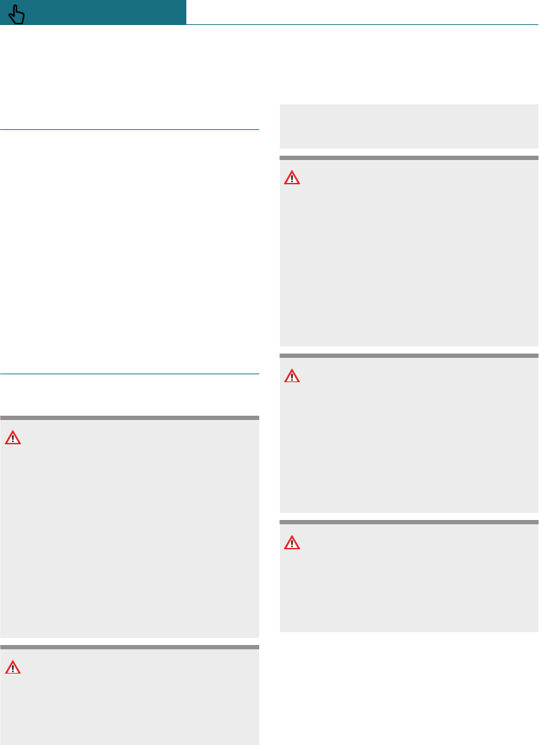
Bracket for rear luggage rack
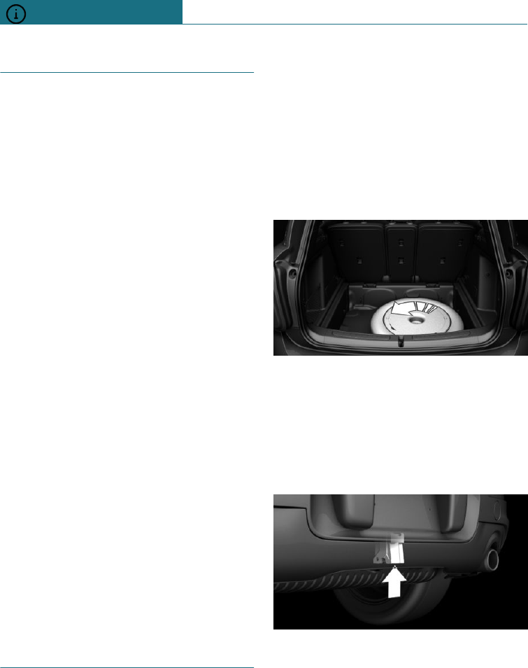
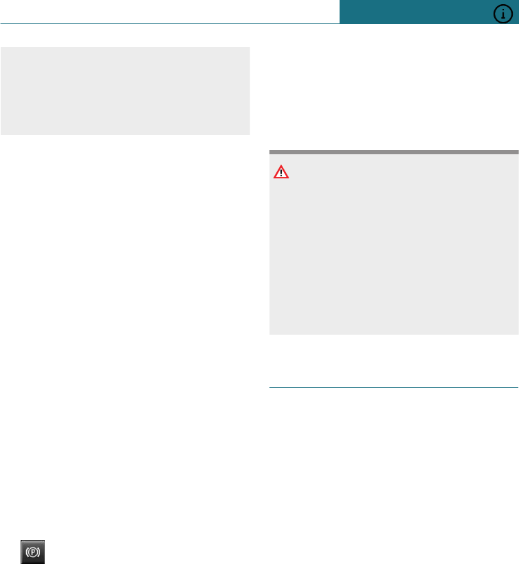
Storage
Removable ball linkage is located under
boot floor.
With emergency wheel
Undo wing stud to remove cover, arrow.
No emergency wheel
The removable ball linkage is located in the
on-board tool kit.
Ball linkage bracket
The bracket for the removable ball linkage
is on the underside of the vehicle.
Follow the maintenance instructions, see
page 328.
Seite 224
DRIVING HINTS Driving precautions
224 Online Edition for Part no. 01402988211 - II/18
Draft
from BA-76
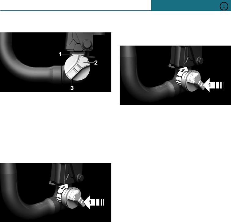
Overview
1Red or green mark
2Lock
3Handwheel
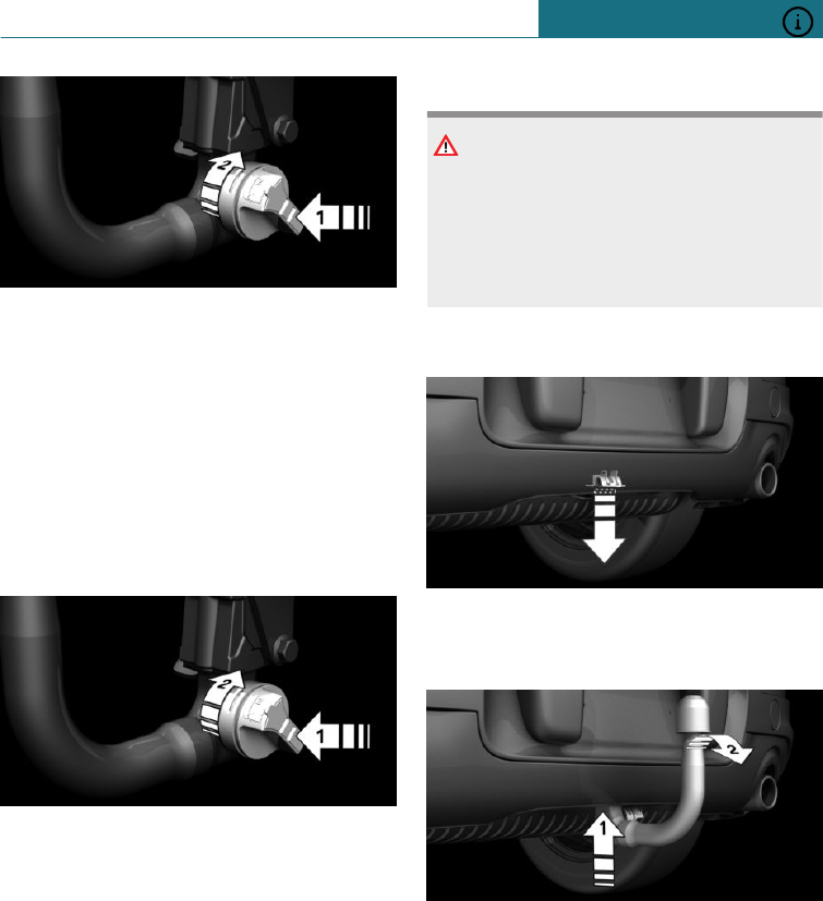
Attaching ball linkage
Before attaching
Unlock the lock with the key.
The lock is unlocked when the handwheel
can be pressed, arrow 1.
Ball linkage can be inserted when red mark
on handwheel is visible. Proceed as follows
if the red mark in the handwheel cannot be
seen:
1. Hold ball linkage firmly.
2. Press the handwheel, arrow 1, and turn
in direction of the arrow as far as it will
go, arrow 2.
3. Handwheel engages.
Seite 225
Driving precautions DRIVING HINTS
225
Online Edition for Part no. 01402988211 - II/18
Draft
from BA-76
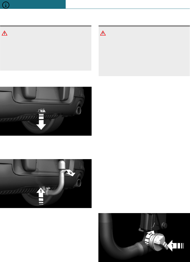
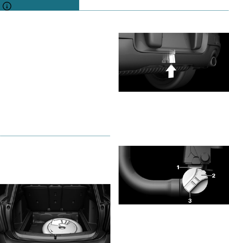
Inserting ball linkage
WARNING
Parts of the body can become trapped
when inserting the ball linkage. There is a
danger of injury. When inserting the ball
linkage, make sure that the area of move-
ment is kept clear.
1. Pull bracket cover downwards and store
in the vehicle.
2. Insert the ball linkage from underneath
into the bracket and push upwards, ar-
row 1.
3. Pull the ball linkage backwards until it
engages, arrow 2.
4. Insert the key into the lock if necessary.
5. Lock the lock in the handwheel.
6. Remove the key.
The ball linkage is locked correctly when
the green mark on the handwheel is visible.
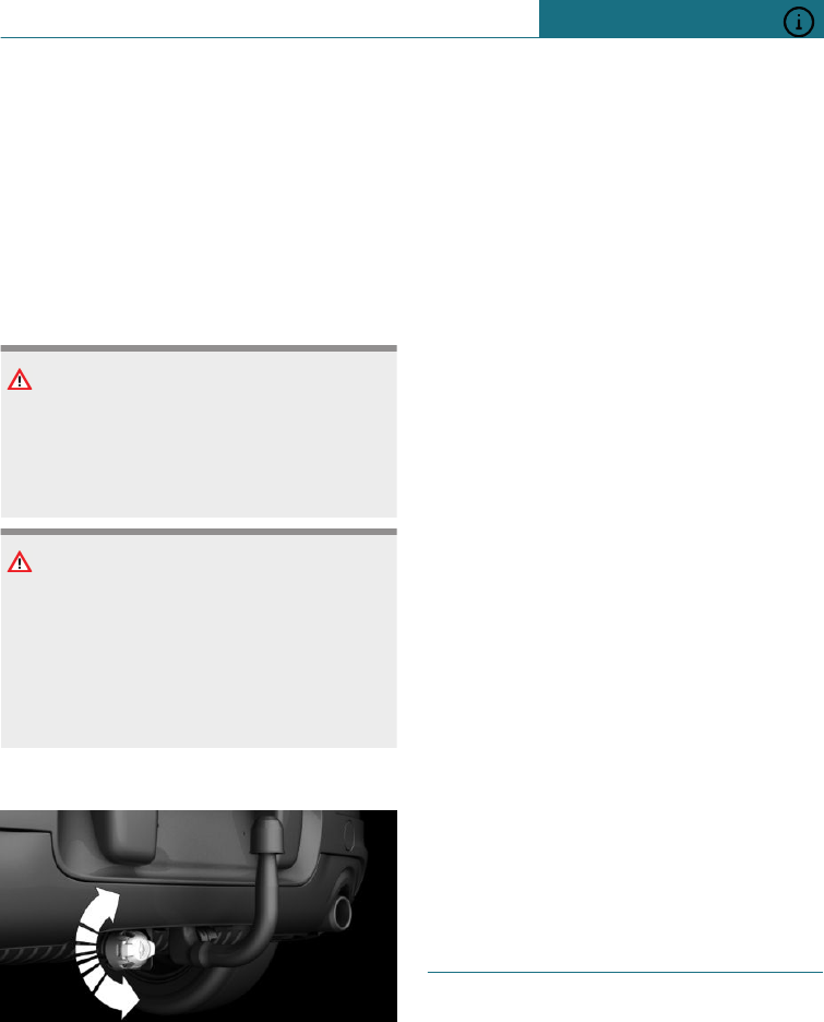
Checking the interlock
WARNING
If the ball linkage is not locked, unstable
driving conditions or accidents can result.
There is a danger of accidents or damage
to property. Before a journey with a trailer
or load carrier, check that the ball linkage
is correctly locked.
Ensure that the ball linkage is properly en-
gaged by shaking it.
If the ball linkage is not fitted firmly, check
the following points:
–Green mark on handwheel is visible.
–Ball linkage is lying flush in the bracket.
–The lock is locked and the key is re-
moved.
Check with a Service Partner of the manu-
facturer or another qualified Service Partner
or a specialist workshop if all points are met
and the ball linkage is not firmly fitted.
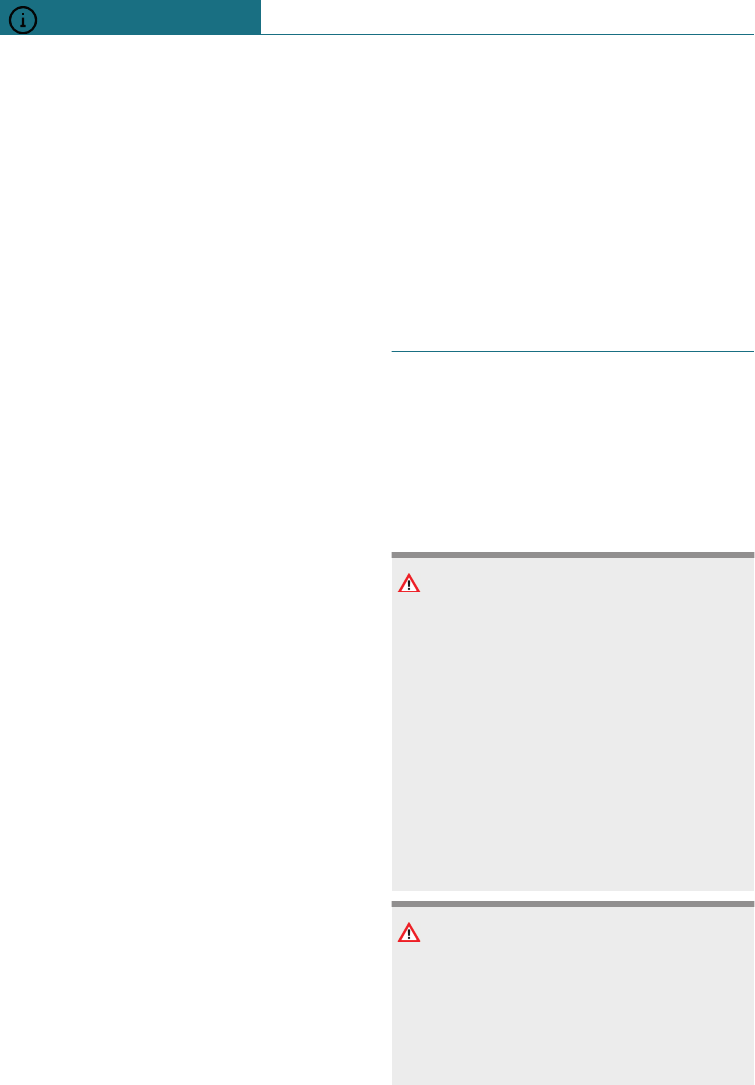
Removing ball linkage
1. Insert key and unlock the lock in the
handwheel.
2. Remove the key.
3. Hold ball linkage firmly.
4. Press the handwheel, arrow 1, and turn
in direction of arrow 2 as far as it will
go.
5. Pull the ball linkage out of the bracket.
Seite 226
DRIVING HINTS Driving precautions
226 Online Edition for Part no. 01402988211 - II/18
Draft
from BA-76
6. Release the handwheel.
7. Insert cover in bracket.
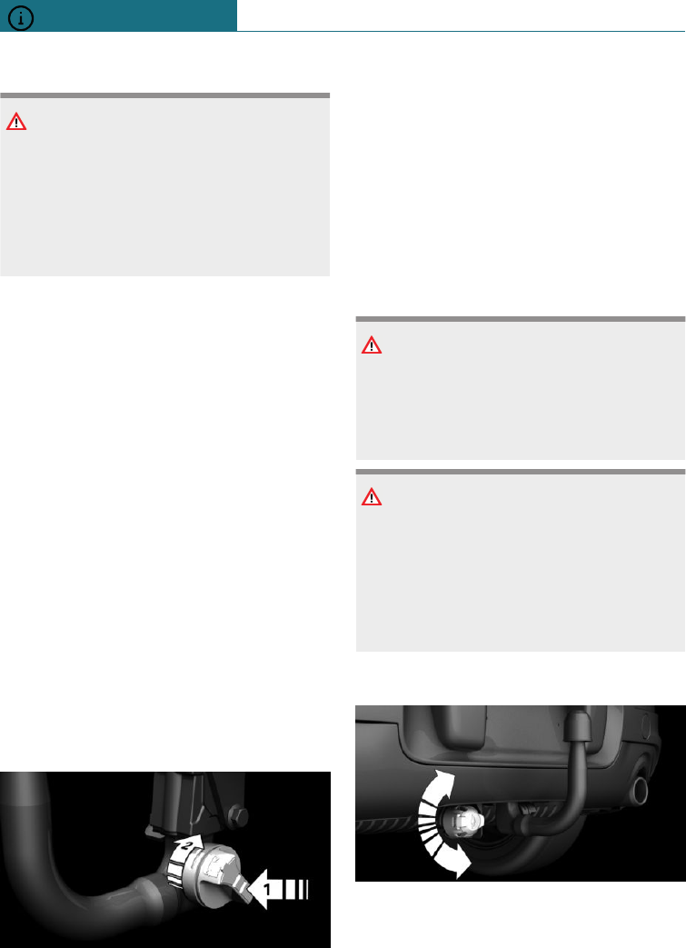
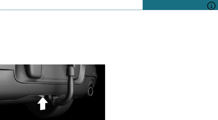
Socket for trailer or rear luggage rack
General
The socket is underneath the bumper next
to the bracket for the ball linkage.
Safety notes
WARNING
The socket for the trailer or rear luggage
rack can heat up due to exhaust gases.
There is a danger of injury. Allow the
trailer socket to cool before swivelling out.
WARNING
The socket for the trailer or rear luggage
rack is located near to protruding parts of
the vehicle body. There is a danger of in-
jury. Do not touch any parts of the body
when swivelling the trailer socket in and
out.
Swivelling in and out
1. Grip the socket at the side.
2. Swivel the socket out in the direction of
the ball linkage or swivel it in towards
the bumper. To make it easier to swivel,
pull the socket back slightly.
3. Swivel the socket out or in up to the end
position.
Fastening
Installation is only possible with the roof
railing.
Loads
A loaded rear luggage rack alters the vehi-
cle's road behaviour and steering response
by shifting its centre of gravity.
When loading and driving, bear the
following in mind:
–Do not exceed permitted axle load or the
permitted gross weight.
–Drive smoothly and avoid sudden accel-
eration, braking or cornering.
Power consumption
Before beginning your journey, check the
function of the trailer rear lights or the rear
luggage rack lights.
The power of the trailer rear lights or rear
luggage rack lights must not exceed the
following values:
–Turn indicators: 42 watts per side.
–Tail lights: 50 watt per side.
–Brake lights: 84 watt total.
–Rear fog lights: 42 watt total.
–Reversing lights: 42 watt total.
Driving on poor road surfaces
Principle
The increased ground clearance means that
the vehicle can be driven on different types
of road surfaces with different properties.
All-wheel drive can help to improve forward
momentum.
Seite 227
Driving precautions DRIVING HINTS
227
Online Edition for Part no. 01402988211 - II/18
Draft
from BA-76

Safety note
NOTE
Objects on unpaved ground, for example
stones or branches, can damage the vehi-
cle. There is a danger of damage to prop-
erty. Do not drive on unpaved terrain.
When driving on poor road
surfaces
For your own safety and the safety of pas-
sengers and the vehicle, observe the
following points:
–Make yourself familiar with the vehicle
before starting the trip and do not take
any risks when driving.
–Adjust speed to the road conditions. The
steeper and more uneven the road, the
slower the speed should be.
–For trips on steep gradients: top up with
engine oil and coolant nearly up to the
MAX mark.
–Avoid contact between the body and the
ground. The ground clearance may vary
depending on the vehicle load.
–If wheels are spinning, accelerate
enough so that drive stability control
systems can distribute drive force to
wheels. If necessary, activate Dynamic
Traction Control DTC.
After driving on bad roads
To maintain driving safety, comply with the
following points:
–Remove any major soiling from the
body.
–Remove mud, snow, ice etc. from the
wheels and tyres and check for damage.
Driving on a racing track
The higher mechanical and thermal loads in-
volved in driving on racing tracks lead to in-
creased wear. This wear is not covered by
the warranty. The vehicle is not conceived
for use in motor sports competitions.
Before driving on a racing track, have the
vehicle checked at a Service Partner of the
manufacturer or another qualified Service
Partner or a specialist workshop.
Seite 228
DRIVING HINTS Driving precautions
228 Online Edition for Part no. 01402988211 - II/18
Draft
from BA-76

Towing a trailer or using rear luggage rack
Vehicle equipment
This chapter describes all standard, country-
specific and special equipment available for
the model series. Therefore equipment
which is not installed in your vehicle, for
example on account of the optional equip-
ment selected or the country specification,
may also be described here. This also ap-
plies to safety-relevant functions and sys-
tems. Comply with the relevant laws and
regulations when using the corresponding
functions and systems.
General
The permitted trailer load is indicated in the
technical data.
Consult a Service Partner of the manufac-
turer or another qualified Service Partner or
a specialist workshop about options for in-
creasing the loads.
The vehicle is equipped with reinforced
springs on the rear axle and, depending on
the type, with a more powerful engine cool-
ing system.
For Australia/New Zealand:
note
Towing
The Australian/New Zealand Standards AS
4177.1-2004 Caravan and light Towing a
trailer components – trailer tow hitches and
towing brackets contains the following
statement, which is hereby accepted by the
BMW Group Australia: FOR TOWING
ONLY. The towbar supplied with your BMW
vehicle should only be used for towing pur-
poses, the towbar assembly should not be
used in conjunction with any towbar-moun-
ted carrying device, such as, for example, a
bicycle carrying rack.
As all BMW Group towbar assemblies are
designed, tested and approved as a single
unit, the practice of modifying or replacing
the BMW supplied towball mount assembly
is not approved. Use only the genuine BMW
towball mount assembly.
BMW Group Australia does not recommend
or support the installation and use of a
Weight Distribution Hitch or Load Level-
ling Device on any BMW Group vehicle.
The use of such devices may affect the vehi-
cle’s warranty status.
We recommend you consult your Author-
ised BMW Dealer for any further advice or
clarification.
Before a journey
Trailer nose weight
If possible, the trailer nose weight should
not be less than the minimum trailer nose
weight of 25 kg, approximately 55 lb. Utilise
the maximum trailer nose weight as much
as possible.
The weight of the trailer tow hitch and the
nose weight reduce the maximum load of
the towing vehicle. The nose weight increa-
ses the vehicle weight. The total permitted
weight of the towing vehicle must not be
exceeded.
Loads
Stow the load as low as possible and as
close as possible to the axle.
Seite 229
Towing a trailer or using rear luggage rack DRIVING HINTS
229
Online Edition for Part no. 01402988211 - II/18
Draft
from BA-76
A low centre of trailer gravity makes the ve-
hicle combination much more stable and
safe to drive.
The permitted total weight of the trailer and
the permitted axle load of the vehicle (see
Technical data) may not be exceeded. The
smaller value is the limit which should be
adhered to.
Tyre inflation pressure
Check the vehicle's and the trailer's tyre in-
flation pressures carefully.
On the vehicle, the tyre inflation pressure,
see page 276, for higher loads applies.
For the trailer, the regulations of the manu-
facturer apply.
Runflat indicator RPA
Reinitialise the runflat indicator RPA after
the tyre inflation pressure has been correc-
ted or a trailer has been attached or de-
tached.
Tyre Pressure Monitor TPM
Reinitialise the Tyre Pressure Monitor TPM
after the tyre inflation pressure has been
corrected or a trailer has been attached or
detached.
Exterior mirrors
Two exterior mirrors which bring both rear
corners of the trailer into your field of view
are required by law. Mirrors of this type are
available as special equipment from a Serv-
ice Partner of the manufacturer or another
qualified Service Partner or a specialist
workshop.
Power consumption
Before beginning your journey, check the
function of the trailer rear lights or the rear
luggage rack lights.
The power of the trailer rear lights or rear
luggage rack lights must not exceed the
following values:
–Turn indicators: 42 watts per side.
–Tail lights: 50 watt per side.
–Brake lights: 84 watt total.
–Rear fog lights: 42 watt total.
–Reversing lights: 42 watt total.
Towing a trailer
General
When the trailer socket is occupied, some
Driver Assistance Systems are unavailable,
or available to a limited extent. A Check
Control message is shown where applicable.
Safety notes
WARNING
Speeds in excess of approximately
80 km/h, approximately 50 mph can be
enough to produce a swaying or fishtailing
motion, depending on the design of trail-
ers and the loads they are carrying. There
is a danger of accidents or damage to prop-
erty.
Keep to an appropriate speed when towing
a trailer. In case of swaying or fishtailing
motions, brake immediately and make the
necessary steering corrections as carefully
as possible.
WARNING
The tyre inflation pressure must be adap-
ted because of the increased axle load
when towing a trailer. Driving with an in-
adequate tyre inflation pressure can dam-
age the tyres. There is a danger of acci-
dents or damage to property. Do not
Seite 230
DRIVING HINTS Towing a trailer or using rear luggage rack
230 Online Edition for Part no. 01402988211 - II/18
Draft
from BA-76
exceed a speed of 100 km/h / 60 mph. In-
crease the tyre inflation pressure of the
towing vehicle by 0.2 bar. Note the maxi-
mum possible tyre inflation pressure sta-
ted on the tyre.
Counteracting snaking
If the trailer begins to snake, the vehicle
combination can only be stabilised by brak-
ing hard immediately.
Make sure that the necessary steering cor-
rections are carried out as cautiously as
possible, taking other road users into con-
sideration.
Upward gradients
In the interest of safety and to avoid hold-
ing up other traffic, do not attempt to climb
upward gradients steeper than 12 % when
towing a trailer.
If higher trailer loads have been retrospec-
tively approved, the limit is 8 %.
Driving off on upward gradients
With Steptronic transmission:The parking
brake is automatically released when the ac-
celerator pedal is pressed.
To prevent the vehicle from rolling back
when driving off, use the parking brake.
1. Shortly before driving off, pull and
hold the switch.
The parking brake remains held as long
as the switch is pulled.
2. To drive off, accelerate and release the
switch.
Downhill gradients
On downward gradients, a vehicle combina-
tion has tendency to snake at an earlier
stage.
Before the downward gradient, shift down
manually to the next-lowest gear and drive
downwards slowly.
High loads and high outside
temperature
NOTE
On long journeys with high trailer loads, a
high outside temperature and a low fuel
tank content, the fuel system can overheat
leading to reduced engine power. There is
a danger of damage to property. Refuel in
good time. Make sure that on long jour-
neys with high trailer loads and a high out-
side temperature, the fuel tank is more
than 1/4 full.
Trailer Stability Control
Principle
The system supports you to neutralise a
trailer's tendency to swing from side to side.
It detects snaking movements and promptly
brakes the vehicle so that road speeds fall to
below the critical range and the vehicle
combination is stabilised.
If the power socket for the trailer is in use
but no trailer is attached, for example dur-
ing use of a bicycle carrier with lighting,
the system may become active in extreme
driving situations.
Operating requirements
The system is operational from a speed of
approximately 65 km/h, approximately
40 mph, when towing a trailer and with the
trailer socket in use.
Seite 231
Towing a trailer or using rear luggage rack DRIVING HINTS
231
Online Edition for Part no. 01402988211 - II/18
Draft
from BA-76
System limits
–The system cannot intervene if the
trailer veers instantly, for example on
slippery or loose road surfaces.
–Trailers with a high centre of gravity
can tip over before a swinging motion is
detected.
–The system is not operational if Dy-
namic Stability Control DSC is deactiva-
ted or has failed.
Not for Australia/New Zea-
land: Trailer tow hitch or rear
luggage rack
Storage
Removable ball linkage is located under
boot floor.
With emergency wheel
Undo wing stud to remove cover, arrow.
No emergency wheel
The removable ball linkage is located in the
on-board tool kit.
Ball linkage bracket
The bracket for the removable ball linkage
is on the underside of the vehicle.
Follow the maintenance instructions, see
page 328.
Overview
1Red or green mark
2Lock
3Handwheel
Attaching ball linkage
Before attaching
Unlock the lock with the key.
Seite 232
DRIVING HINTS Towing a trailer or using rear luggage rack
232 Online Edition for Part no. 01402988211 - II/18
Draft
from BA-76
The lock is unlocked when the handwheel
can be pressed, arrow 1.
Ball linkage can be inserted when red mark
on handwheel is visible. Proceed as follows
if the red mark in the handwheel cannot be
seen:
1. Hold ball linkage firmly.
2. Press the handwheel, arrow 1, and turn
in direction of the arrow as far as it will
go, arrow 2.
3. Handwheel engages.
Inserting ball linkage
WARNING
Parts of the body can become trapped
when inserting the ball linkage. There is a
danger of injury. When inserting the ball
linkage, make sure that the area of move-
ment is kept clear.
1. Pull bracket cover downwards and store
in the vehicle.
2. Insert the ball linkage from underneath
into the bracket and push upwards, ar-
row 1.
3. Pull the ball linkage backwards until it
engages, arrow 2.
4. Insert the key into the lock if necessary.
5. Lock the lock in the handwheel.
6. Remove the key.
The ball linkage is locked correctly when
the green mark on the handwheel is visible.
Seite 233
Towing a trailer or using rear luggage rack DRIVING HINTS
233
Online Edition for Part no. 01402988211 - II/18
Draft
from BA-76
Checking the interlock
WARNING
If the ball linkage is not locked, unstable
driving conditions or accidents can result.
There is a danger of accidents or damage
to property. Before a journey with a trailer
or load carrier, check that the ball linkage
is correctly locked.
Ensure that the ball linkage is properly en-
gaged by shaking it.
If the ball linkage is not fitted firmly, check
the following points:
–Green mark on handwheel is visible.
–Ball linkage is lying flush in the bracket.
–The lock is locked and the key is re-
moved.
Check with a Service Partner of the manu-
facturer or another qualified Service Partner
or a specialist workshop if all points are met
and the ball linkage is not firmly fitted.
Removing ball linkage
1. Insert key and unlock the lock in the
handwheel.
2. Remove the key.
3. Hold ball linkage firmly.
4. Press the handwheel, arrow 1, and turn
in direction of arrow 2 as far as it will
go.
5. Pull the ball linkage out of the bracket.
6. Release the handwheel.
7. Insert cover in bracket.
Socket for trailer or rear luggage
rack
General
The socket is underneath the bumper next
to the bracket for the ball linkage.
Safety notes
WARNING
The socket for the trailer or rear luggage
rack can heat up due to exhaust gases.
There is a danger of injury. Allow the
trailer socket to cool before swivelling out.
WARNING
The socket for the trailer or rear luggage
rack is located near to protruding parts of
the vehicle body. There is a danger of in-
jury. Do not touch any parts of the body
when swivelling the trailer socket in and
out.
Swivelling in and out
1. Grip the socket at the side.
2. Swivel the socket out in the direction of
the ball linkage or swivel it in towards
Seite 234
DRIVING HINTS Towing a trailer or using rear luggage rack
234 Online Edition for Part no. 01402988211 - II/18
Draft
from BA-76
the bumper. To make it easier to swivel,
pull the socket back slightly.
3. Swivel the socket out or in up to the end
position.
Eye for securing cable
There is an eye on the trailer tow hitch
bracket for attaching the trailer securing ca-
ble.
For increased safety when towing a trailer
during a journey, attach the trailer securing
cable to the eye.
Check that the securing cable can move
freely and is not dragging on the ground.
Seite 235
Towing a trailer or using rear luggage rack DRIVING HINTS
235
Online Edition for Part no. 01402988211 - II/18
Draft
from BA-76

Saving fuel
Vehicle equipment
This chapter describes all standard, country-
specific and special equipment available for
the model series. Therefore equipment
which is not installed in your vehicle, for
example on account of the optional equip-
ment selected or the country specification,
may also be described here. This also ap-
plies to safety-relevant functions and sys-
tems. Comply with the relevant laws and
regulations when using the corresponding
functions and systems.
General
The vehicle possesses wide-ranging tech-
nologies for reducing consumption and
emission levels.
Fuel consumption depends on various fac-
tors.
A number of measures, driving style and
regular maintenance can influence the fuel
consumption and the burden on the envi-
ronment.
Remove transported load that
is not required
Extra weight increases fuel consumption.
Remove add-on parts after use
If no longer required, remove auxiliary mir-
rors, roof racks and rear-mounted racks af-
ter use.
Add-on parts on the vehicle interfere with
its aerodynamic performance and increase
fuel consumption.
Closing windows and the
Glass Roof
An opened Glass Roof or opened window in-
crease drag and consequently fuel consump-
tion.
Tyres
General
Tyres can have differing effects on fuel con-
sumption. For example, fuel consumption
can be affected by tyre size.
Checking tyre inflation pressure
regularly
Check and, if necessary, correct the tyre in-
flation pressures at least twice a month and
before setting off on a longer journey.
Insufficient tyre inflation pressure enlarges
the rolling resistance and thus increases
fuel consumption and tyre wear.
Drive off immediately
Do not warm up the engine with the vehicle
at a standstill; it is preferable to set off
straight away, driving at moderate engine
speeds.
A cold engine will then reach its operating
temperature faster.
Seite 236
DRIVING HINTS Saving fuel
236 Online Edition for Part no. 01402988211 - II/18
Draft
from BA-76

Drive with foresight
Anticipating the road situation and adopt-
ing a smooth driving style will reduce fuel
consumption.
Avoid accelerating and braking unnecessa-
rily.
Keep an appropriate distance from the pre-
ceding vehicle.
Avoid high engine speeds
Driving at low engine speeds lowers fuel
consumption and wear.
Pay attention to the shift point indicator,
see page 133, in the vehicle, if fitted.
Steptronic transmission:
coasting function
Principle
The function helps to save fuel.
To do this, the engine is automatically dis-
connected from the gearbox in selector
lever position D under certain circumstan-
ces. The vehicle continues to roll in idle to
reduce consumption. Selector lever position
D remains engaged.
This vehicle condition is called coasting.
As soon as the brake or accelerator pedal is
pressed, the engine is automatically recon-
nected.
General
Coasting is a component of GREEN drive
mode and MID drive mode.
Coasting is automatically activated by call-
ing up GREEN drive mode or MID drive
mode via the MINI driving mode switch. It
cannot be deactivated.
A precautionary driving style helps to use
the function as often as possible and sup-
ports the consumption-reducing effect of
coasting.
Operating requirements
The function is available in the speed range
from approx. 25 km/h, 15 mph up to
160 km/h, 100 mph.
The function is active if the following con-
ditions are met:
–System detects a calm and smooth driv-
ing style.
–Accelerator pedal not pressed.
–Brake pedal not pressed or only pressed
lightly.
–Selector lever in selector lever position
D.
–Engine and gearbox are at operating
temperature.
–With a camera in the area of the rear-
view mirror: the system does not detect
any vehicles ahead of you.
–With the route-ahead assistant: the sys-
tem does not detect any obstructive
traffic situations or routes.
Operation via shift paddles
Principle
The coasting state can be controlled via the
shift paddles, if installed.
Activating/deactivating coasting via
shift paddles
1. Pull the right-hand shift paddle to shift
to top gear.
2. To activate coasting mode, actuate the
right-hand shift paddle again.
Seite 237
Saving fuel DRIVING HINTS
237
Online Edition for Part no. 01402988211 - II/18
Draft
from BA-76

Actuate the left-hand shift paddle to deacti-
vate.
Display in the instrument cluster
The revolution counter is showing idle
speed.
Make use of overrun mode
When approaching a red traffic light, take
your foot off the accelerator and allow the
vehicle to roll.
On downward stretches, take your foot off
the accelerator and allow the vehicle to roll.
The fuel supply is interrupted in overrun
mode.
Switch off the engine if stop-
ping for a relatively long time
Stopping the engine
When you stop the vehicle for longer peri-
ods, for example at traffic lights, railway
crossings or in traffic jams, switch off the
engine.
Auto Start Stop function
The Auto Start Stop function of the vehicle
shuts off the engine automatically during a
stop.
If the engine is switched off and then star-
ted again, the fuel consumption and emis-
sions are reduced compared with a perma-
nently running engine. Savings can be made
just by stopping the engine for a few sec-
onds.
Fuel consumption also depends on other
factors, such as driving style, road condi-
tions, maintenance or environmental fac-
tors, for example.
Switch off functions which
are not currently required
Functions such as seat heating or rear win-
dow heating require a great deal of energy
and consume additional fuel, especially in
city traffic and stop-and-go traffic.
Switch these functions off if they are not re-
quired.
Have maintenance work car-
ried out
Have the vehicle serviced regularly to ach-
ieve optimal economy and lifetime. MINI
recommends having maintenance work car-
ried out by a MINI Service Partner.
Please also see the MINI Maintenance Sys-
tem, see page 302.
GREEN Mode
Principle
GREEN Mode supports a fuel-saving driving
style. To do this, the engine management
and comfort functions, such as for example
the air conditioning power, are adjusted.
With Steptronic transmission:
The engine is disconnected from the gear-
box in selector lever position D under cer-
tain circumstances. The vehicle rolls when
idling to optimise fuel consumption. Selec-
tor lever position D remains engaged.
In addition, situation-dependent notes can
be displayed which help you to drive as
fuel-efficiently as possible.
In the instrument cluster, the extension of
the range achieved as a result can be dis-
played as a bonus range.
Seite 238
DRIVING HINTS Saving fuel
238 Online Edition for Part no. 01402988211 - II/18
Draft
from BA-76
General
The system comprises the following func-
tions and displays:
–GREEN bonus range, see page 239.
–GREEN tip, driving instruction, see
page 240.
–GREEN air conditioning, see page 239.
–Coasting driving state, see page 240.
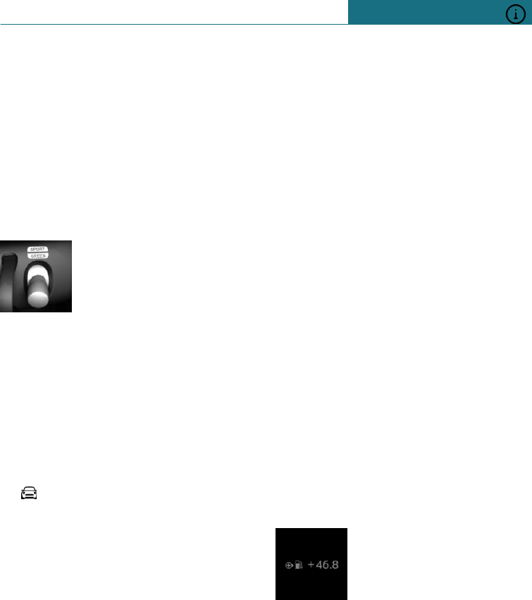
Activating GREEN Mode
Press the MINI Driving Modes
switch downwards until
GREEN is displayed in the in-
strument cluster.
Configuring GREEN
Using MINI Driving Modes switch
1. Activate GREEN Mode.
2. "Configure GREEN"
3. Select the desired setting.
Using the on-board monitor
1. "My MINI"
2. "Vehicle settings"
3. If necessary, "Driving mode"
4. "Configure GREEN"
5. Select the desired setting.
Enabling/disablingfunctions
The following functions can be activated /
deactivated:
–"GREEN limit":
–"GREEN climate control"
–"Coasting"
The settings are saved for the currently
used driver profile.
GREEN limit
–Activate GREEN limit:
"GREEN limit":
A GREEN tip is shown when the speed
of the set GREEN limit is exceeded.
–Setting speed for the GREEN limit:
"Tip at:"
Select the required speed.
GREEN air conditioning
The air conditioning is adjusted for efficient
fuel consumption.
A slight deviation from the temperature set
and/or a longer heating up and/or cooling
down of the interior is therefore possible, in
order to lower consumption.
The power to the seat heating and exterior
mirror heating is also reduced.
GREEN saving potential
The potential saving that can be achieved
with the current configuration is shown as
a percentage.
Display in the instrument cluster
GREEN bonus range
An extension of range can be
achieved due to adjusted driv-
ing style.
This can be displayed as bo-
nus range in the instrument
cluster.
The bonus range is contained in the display
of the range.
After filling up, the bonus range is automat-
ically reset.
–Green display: efficient driving style.
–Grey display: adjust driving style, for ex-
ample, by easing off the accelerator.
Seite 239
Saving fuel DRIVING HINTS
239
Online Edition for Part no. 01402988211 - II/18
Draft
from BA-76
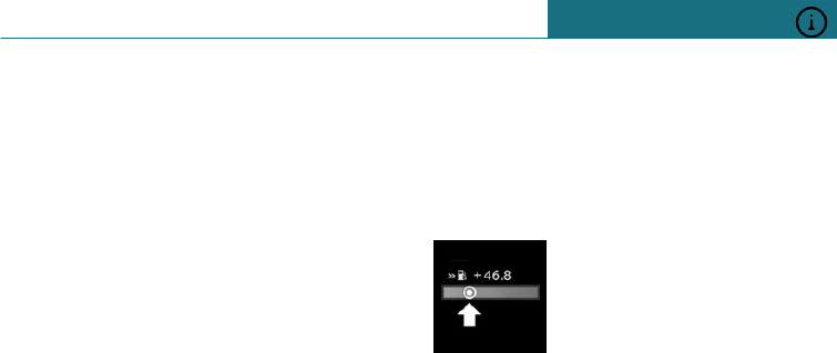
Efficiency display
In the instrument cluster, a
marking in the bar display
shows the current efficiency
of the driving style.
Marking in the left area, ar-
row 1: display of the energy recuperation
achieved when coasting or when braking.
Marking in the right area, arrow 2: display
when accelerating.
The efficiency of the driving style is shown
by the position of the bar:
–Marking within the green range: effi-
cient driving style.
–Marking outside the green range: adjust
driving style, such as by removing your
foot from the accelerator.
GREEN tip, driving instruction
The GREEN tip shows that the driving style
can be adjusted to be more efficient on fuel
consumption, for example by accelerating
less.
Activating the efficiency display and
GREEN tips
The efficiency display and GREEN tips ap-
pear in the instrument cluster when GREEN
Info is activated.
Using the on-board monitor:
1. "My MINI"
2. "System settings"
3. "Displays"
4. "Instrument cluster"
5. "GREEN information"
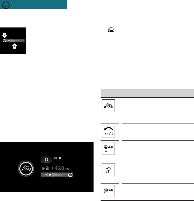
GREEN tip, symbols
An additional symbol and text instruction
are shown.
Symbol Measure
For an efficient driving style,
look well ahead when driving
and accelerate and decelerate
conservatively.
Reduce speed to the selected
GREEN speed.
Steptronic transmission:
Shift from M/S to D and avoid
manual changes.
Manual gearbox:
Follow gearshift recommenda-
tion.
Manual gearbox:
Engage neutral to stop engine.
Coasting
Principle
The function helps to save fuel.
To do this, the engine is automatically dis-
connected from the gearbox in selector
lever position D under certain circumstan-
ces. The vehicle continues to roll in idle to
reduce consumption. Selector lever position
D remains engaged.
This vehicle condition is called coasting.
Seite 240
DRIVING HINTS Saving fuel
240 Online Edition for Part no. 01402988211 - II/18
Draft
from BA-76
As soon as the brake or accelerator pedal is
pressed, the engine is automatically recon-
nected.
General
Coasting is a component of the GREEN
drive mode.
Calling up the GREEN drive mode via the
MINI Driving Modes switch, see page 172,
automatically activates coasting.
A precautionary driving style helps to use
the function frequently and supports the
consumption-reducing effect of coasting.
Operating requirements
The function is available in the speed range
from approx. 25 km/h, 15 mph up to
160 km/h, 100 mph.
–Accelerator pedal and brake pedal are
not operated.
–Selector lever is in selector lever posi-
tion D.
–Engine and gearbox are at operating
temperature.
–With a camera in the area of the rear-
view mirror: the system does not detect
any vehicles ahead of you.
–With the route-ahead assistant: the sys-
tem does not detect any obstructive
traffic situations or routes.
Operation via shift paddles
Principle
The coasting state can be controlled via the
shift paddles, if installed.
Activating/deactivating coasting via shift
paddles
1. Pull the right-hand shift paddle to shift
to top gear.
2. To activate coasting mode, actuate the
right-hand shift paddle again.
Actuate the left-hand shift paddle to deacti-
vate.
Display
Display in the instrument cluster
The bar display underneath
the rev counter is marked in
green and the marking is at
zero. The revolution counter is
showing idle speed.
System limits
The function is not available if one of the
following conditions is met:
–DSC OFF and TRACTION are activated.
–The Cruise Control is activated.
–When driving in the handling limit
range.
–When driving on steep uphill or down-
hill inclines.
–When towing a trailer.
–The battery charge state is temporarily
too low.
–The vehicle's electrical system is draw-
ing too much current.
Seite 241
Saving fuel DRIVING HINTS
241
Online Edition for Part no. 01402988211 - II/18
Draft
from BA-76
242
Online Edition for Part no. 01402988211 - II/18
Draft
from BA-76

ENTERTAINMENT
General ...................................................................................................... 244
Sound ......................................................................................................... 246
Radio .......................................................................................................... 248
Audio ......................................................................................................... 252
243
Online Edition for Part no. 01402988211 - II/18
Draft
from BA-76
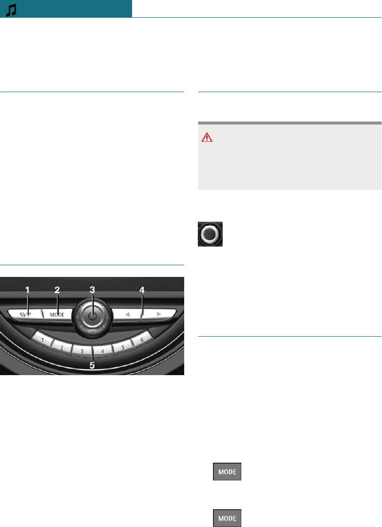
General
Vehicle equipment
This chapter describes all standard, country-
specific and special equipment available for
the model series. Therefore equipment
which is not installed in your vehicle, for
example on account of the optional equip-
ment selected or the country specification,
may also be described here. This also ap-
plies to safety-relevant functions and sys-
tems. Comply with the relevant laws and
regulations when using the corresponding
functions and systems.
Controls
1Activating/deactivating traffic informa-
tion
2Switching entertainment sources
3Sound output on/off, volume
4Changing station/track
5Favourites buttons
Sound output
Safety note
WARNING
Having the sound set to a high volume can
damage your hearing. There is a danger of
injury. Do not set a high volume.
Volume and sound output
–Turn the knob to set the volume.
–Press the knob to switch off the
sound output. Pressing again re-
stores the previous volume.
Playback of audio recordings is stopped
when muting is active.
Entertainment sources
General
Possible entertainment sources:
–Radio, see page 248.
–USB audio, see page 252.
–Bluetooth audio, see page 252.
Changing the entertainment source
On the radio:
1. Press the button.
A list of all currently available entertain-
ment sources is displayed.
2. Press the button again to select
an entertainment source.
Seite 244
ENTERTAINMENT General
244 Online Edition for Part no. 01402988211 - II/18
Draft
from BA-76
Using the on-board monitor:
1. "Media/Radio"
A list of all possible entertainment sour-
ces is displayed.
2. Select the desired entertainment source.
Via the button on the Controller:
1. Press the button.
The entertainment source last selected
is played.
2. Press the button again.
A list of all currently available entertain-
ment sources is displayed.
3. Select the desired entertainment source.
Adapting the selection list for the
entertainment sources
It is possible to select which entertainment
sources are displayed in the selection list.
The entertainment source currently being
played cannot be removed from the selec-
tion list.
1. "Media/Radio"
A list of all possible entertainment sour-
ces is displayed.
2. "Personalise menu"
3. Select the desired setting.
Seite 245
General ENTERTAINMENT
245
Online Edition for Part no. 01402988211 - II/18
Draft
from BA-76
Sound
Vehicle equipment
This chapter describes all standard, country-
specific and special equipment available for
the model series. Therefore equipment
which is not installed in your vehicle, for
example on account of the optional equip-
ment selected or the country specification,
may also be described here. This also ap-
plies to safety-relevant functions and sys-
tems. Comply with the relevant laws and
regulations when using the corresponding
functions and systems.
General
Settings are saved in the currently used
driver profile.
Treble, bass, balance, fader
1. "Media/Radio"
2. "Sound"
3. Select the desired setting:
–"Treble": treble adjustment.
–"Bass": bass adjustment.
–"Balance": left/right volume distribu-
tion.
–"Fader": front/rear volume distribu-
tion.
4. To adjust: turn the Controller.
5. To save: press the Controller.
Volume compensation
To compensate for the increasing driving
noise at higher speeds, it is possible to set
an automatic volume increase.
1. "Media/Radio"
2. "Sound"
3. "Volume settings"
4. Select the desired setting:
–"Speed volume": ratio between the
volume of the entertainment source.
–"PDC": ratio of the PDC acoustic sig-
nal volume to the volume of the en-
tertainment source.
The basic setting ensures that the
acoustic signal will be heard at any
volume.
–"Gong": ratio of the acoustic signal
volume, for example for seat belt re-
minder, to the volume of the enter-
tainment source.
The basic setting ensures that the
acoustic signal will be heard at any
volume.
–"Microphone": sensitivity of the mi-
crophone during a telephone call.
The adjustment is performed during
the telephone call and is stored for
the mobile telephone being used.
–"Loudspeakers": loudspeaker volume
during a telephone call.
Playback of audio recordings is stop-
ped when muting is active.
The adjustment is performed during
the telephone call and is stored for
the mobile telephone being used.
Seite 246
ENTERTAINMENT Sound
246 Online Edition for Part no. 01402988211 - II/18
Draft
from BA-76

Radio
Vehicle equipment
This chapter describes all standard, country-
specific and special equipment available for
the model series. Therefore equipment
which is not installed in your vehicle, for
example on account of the optional equip-
ment selected or the country specification,
may also be described here. This also ap-
plies to safety-relevant functions and sys-
tems. Comply with the relevant laws and
regulations when using the corresponding
functions and systems.
General
Settings are saved in the currently used
driver profile.
AM/FM stations
General
Depending on the equipment installed and
the country specifications, it may not be
possible to receive AM stations.
Radio Data System RDS
Principle
RDS broadcasts additional information on
the FM waveband, for example the station
name.
If a station has a number of frequencies, an
automatic switch to the frequency with the
best reception quality is made when re-
quired.
It is recommended that you switch on RDS.
Switching on/off
1. "Media/Radio"
2. "FM"
3. Press the button.
4. "RDS"
Selecting a station
1. "Media/Radio"
2. "FM" or "AM"
The station last played is played and the
station list is shown.
3. Select the desired station.
Changing stations
On the radio:
Press the left or right button.
The previous or next station from the sta-
tion list is played.
Saving stations
General
A symbol next to the highlighted station in-
dicates whether the station has already
been saved.
Symbol Meaning
Station has not been saved.
Station has already been saved.
Saving the station being played
1. "Media/Radio"
2. "FM" or "AM"
3. Tilt the Controller to the left.
Seite 248
ENTERTAINMENT Radio
248 Online Edition for Part no. 01402988211 - II/18
Draft
from BA-76
4. "Save station"
The memory list is displayed.
5. Select the desired memory location.
Saving a station that is not being
played
1. "Media/Radio"
2. "FM" or "AM"
3. Highlight the desired station.
4. Press and hold the Controller until the
memory list is displayed.
5. Select the desired memory location.
The channels can also be saved to the Fa-
vourites buttons, see page 40.
Manual station selection
Station selection via frequency.
1. "Media/Radio"
2. "FM" or "AM"
3. Tilt the Controller to the left.
4. "Manual search"
5. To select the frequency: turn the Con-
troller.
6. To save the frequency: press the Con-
troller.
Renaming a station
When saving a station with an RDS signal,
the RDS information transferred during sav-
ing is adopted as the station name. This
name can be changed.
1. "Media/Radio"
2. "FM"
3. Select the desired station.
4. Press the button.
5. "Rename as:"
If necessary, wait until the name of the
desired station is displayed.
6. Press the Controller to save this name.
Displaying additional station
information
If a radio station broadcasts Radio Text or
Radio Text Plus data, this information, for
example the track or artist of the piece of
music, can be shown. The availability, con-
tent and sequence depend on the radio sta-
tion.
1. "Media/Radio"
2. "FM"
3. Select the desired station.
4. Press the button.
5. "Station information"
Digital radio DAB/DMB
Principle
Digital stations can broadcast several shows
simultaneously on one frequency. The col-
lection of stations for a particular frequency
is called an ensemble. Some stations feature
additional programmes. Sports stations, for
example, may broadcast various sports
events at the same time.
Depending on what the station provides, ad-
ditional information or even images trans-
mitted by the station can be shown.
Selecting a station
1. "Media/Radio"
2. "DAB" or "DAB/DMB"
The station last played is played and the
station list is shown.
3. Select station.
Seite 249
Radio ENTERTAINMENT
249
Online Edition for Part no. 01402988211 - II/18
Draft
from BA-76
DAB: information on the station and pro-
gram currently playing is shown. The availa-
bility, content and sequence depend on the
radio station.
Changing stations
On the radio:
Press the left or right button.
The previous or next station from the sta-
tion list is played.
Saving stations
General
A symbol next to the highlighted station in-
dicates whether the station has already
been saved.
Symbol Meaning
Station has not been saved.
Station has already been saved.
Saving the station being played
1. "Media/Radio"
2. "DAB" or "DAB/DMB"
3. Tilt the Controller to the left.
4. "Save station"
The memory list is displayed.
5. Select the desired memory location.
Saving a station that is not being
played
1. "Media/Radio"
2. "DAB" or "DAB/DMB"
3. Highlight the desired station.
4. Press and hold the Controller until the
memory list is displayed.
5. Select the desired memory location.
The channels can also be saved to the Fa-
vourites buttons, see the Owner's Handbook
for the vehicle.
Additional information
If a radio station broadcasts RadioText or
RadioText Plus, this information can be dis-
played. Such information might be, for ex-
ample the track or artist of a piece of music,
or the telephone number or e-mail address
of the radio station. The availability, content
and sequence depend on the radio station.
1. "Media/Radio"
2. "DAB" or "DAB/DMB"
3. Select the desired station.
4. Press the button.
5. "Station information"
Automatic station following
General
If reception is poor, a search is run for the
same station in another ensemble. If the
station can be received better in another
ensemble, an automatic switch is made.
If station tracking is activated, the station
is additionally searched for in the analogue
frequency band. If it is not available in an-
other ensemble, the station's analogue fre-
quency is switched to instead. This change-
over is only possible if the corresponding
station's signal is available in adequate
quality and the IDs of the stations match.
Switching on automatic station
following
1. "Media/Radio"
2. "DAB" or "DAB/DMB"
3. Press the button.
4. "DAB station following"
Seite 250
ENTERTAINMENT Radio
250 Online Edition for Part no. 01402988211 - II/18
Draft
from BA-76
Electronic programme guide
Several stations broadcast an electronic pro-
gramme guide for their programme.
1. "Media/Radio"
2. "DAB" or "DAB/DMB"
3. Tilt the Controller to the left.
4. "DAB programme"
All available programme guides are dis-
played.
For each programme, the programme cur-
rently being broadcast and the next pro-
gramme are displayed.
Select the desired entry to show the details
on a programme.
Enlarging an image
If a radio station transmits images, these
are shown. The image display can be shown
enlarged.
1. "Media/Radio"
2. "DAB" or "DAB/DMB"
3. Tilt the Controller to the left.
4. "Enlarge image"
Saved stations
General
40 stations can be saved.
Selecting a station
1. "Media/Radio"
2. "Saved stations"
3. Select the desired station.
Deleting a station
1. "Media/Radio"
2. "Saved stations"
3. Highlight the station to be deleted.
4. Press the button.
5. "Delete entry"
Traffic information
Activating/deactivating
On the radio:
Press the button.
Interrupting
Press one of the following buttons on the
radio during the traffic announcement:
–
–
–"Cancel traffic information"
To adjust the volume
Turn the knob during a traffic an-
nouncement until the desired vol-
ume is obtained.
Note the following regarding volume set-
ting:
–The set volume is not saved.
–At the start of each journey, the volume
of the traffic announcements is adapted
to the volume of the entertainment
source playback.
–The volume cannot be reduced further
beyond the point at which the traffic an-
nouncement is still plainly audible.
Seite 251
Radio ENTERTAINMENT
251
Online Edition for Part no. 01402988211 - II/18
Draft
from BA-76

Audio
Vehicle equipment
This chapter describes all standard, country-
specific and special equipment available for
the model series. Therefore equipment
which is not installed in your vehicle, for
example on account of the optional equip-
ment selected or the country specification,
may also be described here. This also ap-
plies to safety-relevant functions and sys-
tems. Comply with the relevant laws and
regulations when using the corresponding
functions and systems.
General
Music tracks, audiobooks and podcasts can
be played. The sound is output via the vehi-
cle loudspeakers.
The settings are saved for the currently
used driver profile.
Depending on the equipment installed, the
following audio sources can be used:
Symbol Meaning
USB device.
Bluetooth audio.
USB device
Formats that can be played
Popular audio formats, for example MP3,
AAC or WMA, can be played.
Apple iPod/iPhone
The Apple iPod/iPhone music search and
music playback functions are supported.
Audio players and storage media
with USB port
Information on all tracks, for example artist,
genre or track, as well as the playlists are
transferred to the vehicle. This might take
some time, depending on the USB device,
file size and number of tracks.
During transfer, the tracks can be called up
via the file directory.
The information for approx. 10,000 tracks
can be saved in the vehicle.
Music tracks with integrated Digital Rights
Management DRM cannot be played.
Selecting the USB device
Information on the USB interface, see
page 206.
1. Connect the USB device to the USB in-
terface.
It is best to use the adapter cable sup-
plied with the USB device.
2. "Media/Radio"
3. "USB"
Or:
Select the name of the USB device.
Further descriptions for playback, see
page 253.
Bluetooth audio
General
–Playback of music files via Bluetooth
from external devices, for example audio
devices or mobile telephones.
Seite 252
ENTERTAINMENT Audio
252 Online Edition for Part no. 01402988211 - II/18
Draft
from BA-76
–The volume of the sound output depends
on the device. If applicable, change vol-
ume settings on the device.
–Up to four external devices can be con-
nected to the vehicle.
Operating requirements
–The Bluetooth device is connected with
the vehicle.
–Bluetooth audio playback has been acti-
vated.
Selecting a Bluetooth device
1. "Media/Radio"
2. Select the required Bluetooth device
from the list.
Further descriptions for playback, see
page 253.
If the Bluetooth device is not listed in the
device list, Bluetooth audio playback may
have not been activated. Proceed as follows
to activate Bluetooth audio playback:
1. "Media/Radio"
2. "Manage mobile devices"
3. Select the required Bluetooth device.
4. "Bluetooth audio"
Playback
General
Once an audio source has been selected, in-
formation about playback appears on the
Control Display.
The Control Display shows the available in-
formation about the current track and the
playlist. The content and scope of the play-
list depends on the selected audio source
and the search criteria used.
The selected playlist is displayed in the case
of USB and Bluetooth devices. This can be
the result of a search or a previously saved
playlist.
Tilting the Controller to the left displays
further functions. The extent of applications
available depends on the selected audio
source.
With Bluetooth devices, the extent of appli-
cations that can be operated using the on-
board monitor may be limited depending on
the supported Bluetooth version. If neces-
sary, the missing functions can be operated
directly on the device.
Selecting a track
Select the desired track from the playlist.
All tracks in the playlist are played, starting
from the selected track.
Changing the track
On the radio:
Press the left or right button.
The previous or next track from the playlist
is played.
Fast forward/rewind
On the radio:
Press and hold the left or right but-
ton.
Search criteria
General
The possible search criteria depend on the
selected audio source.
Seite 253
Audio ENTERTAINMENT
253
Online Edition for Part no. 01402988211 - II/18
Draft
from BA-76
Searching for track information
The following search criteria relate to the
data saved in the track information.
1. Tilt the Controller to the left.
2. "Media search"
3. Select the desired setting:
–"Search"
All tracks are displayed which have
track information containing the en-
tered search term. The more charac-
ters are entered, the more tightly the
result is restricted.
Tilt the Controller to the right to dis-
play the list of results.
–"Genres"
A list of all available genres is dis-
played.
Once a genre has been selected, all
matching artists are displayed.
–"Artists"
A list of all available artists is dis-
played.
Once an artist has been selected, all
matching albums and tracks are dis-
played.
–"Albums"
A list of all available albums is dis-
played.
Once an album has been selected, all
matching tracks are displayed.
–"Tracks"
A list of all available tracks is dis-
played.
4. If necessary, select an album.
5. Select the track you want to start to play
back.
The search for artists and tracks can also be
directly selected.
1. Tilt the Controller to the left.
2. "Artists" or "Tracks"
Tracks which do not contain the selected
search criterion are grouped as "unknown".
Tracks without track information can only
be found via the directory structure.
Searching for playlists
1. Tilt the Controller to the left.
2. "Media search"
3. "Playlists"
A list of all available playlists is dis-
played.
4. Select the playlist.
5. Select the track you want to start to play
back.
Information about playback appears on
the Control Display. The playlist corre-
sponds to the track list resulting from
the search.
Searching for other media
Depending on the USB device and the
equipment, audio books and podcasts can
be searched for separately.
1. Tilt the Controller to the left.
2. "Media search"
3. Select the desired setting:
–"Podcasts"
A list of all available podcasts is dis-
played.
–"Audio books"
A list of all available audio books is
displayed.
4. Select the track you want to start to play
back.
Information about playback appears on
the Control Display. The playlist corre-
sponds to the track list resulting from
the search.
Seite 254
ENTERTAINMENT Audio
254 Online Edition for Part no. 01402988211 - II/18
Draft
from BA-76

Searching in the folder structure
It is possible to search the USB devices via
the directory structure.
The names of the folders and tracks corre-
spond to the folder and file names. The
folder and file names may differ from the
names in the track information.
1. Tilt the Controller to the left.
2. "Media search"
3. "Browse folder"
4. Change to a subfolder if necessary.
Select the track you want to start to play
back.
Information about playback appears on
the Control Display. The playlist corre-
sponds to the track list resulting from
the search.
Shuffle
The current playlist or all tracks on the se-
lected audio source are played in random or-
der.
1. Tilt the Controller to the left.
2. "Shuffle"
Seite 255
Audio ENTERTAINMENT
255
Online Edition for Part no. 01402988211 - II/18
Draft
from BA-76
256
Online Edition for Part no. 01402988211 - II/18
Draft
from BA-76

COMMUNICATION
Telephone ................................................................................................. 258
MINI Connected ..................................................................................... 262
257
Online Edition for Part no. 01402988211 - II/18
Draft
from BA-76
Telephone
Vehicle equipment
This chapter describes all standard, country-
specific and special equipment available for
the model series. Therefore equipment
which is not installed in your vehicle, for
example on account of the optional equip-
ment selected or the country specification,
may also be described here. This also ap-
plies to safety-relevant functions and sys-
tems. Comply with the relevant laws and
regulations when using the corresponding
functions and systems.
Telephone functions
General
Mobile telephones can be connected to the
vehicle using Bluetooth. Registering and
connecting mobile telephone with the vehi-
cle, see page 45.
At high temperatures, the charging function
of the mobile telephone can be restricted
and no longer operate.
To avoid malfunctions, a mobile telephone
which is connected to the vehicle should
not be operated with the phone's keypad.
When using the mobile telephone through
the vehicle, follow the user manual of the
mobile telephone.
Safety note
WARNING
Operating integrated informations systems
and communication devices during the
journey may distract you from the traffic.
You could lose control of the vehicle.
There is a danger of accidents. Only oper-
ate the systems or devices if permissible
in the traffic situation. Stop if necessary
and operate the systems or devices with
the vehicle at a standstill.
Incoming call
If the number of the caller is saved in the
telephone book and is transferred from the
network, the name of the contact is dis-
played. Otherwise, only the phone number
is displayed.
Accepting a call
Incoming calls can be accepted in different
ways.
–Using on-board monitor:
"Accept"
– Press the button on the steering
wheel.
Rejecting a call
"Reject"
Ending a call
–Using on-board monitor:
"End call"
– Press the button on the steering
wheel.
Last calls
The last outgoing, missed and incoming
calls are transferred to the vehicle. Depend-
ing on the equipment version, the transfer
is from the main and additional telephone.
Seite 258
COMMUNICATION Telephone
258 Online Edition for Part no. 01402988211 - II/18
Draft
from BA-76
Displays
1. "Communication"
2. "Recent calls"
3. The last 20 calls are displayed.
Filtering the call list
1. "Calls:"
2. Select the desired setting.
Dialling a number from the list
Select from the list. The call is established
using the mobile telephone from which the
entry came.
Using options: start the call using the sec-
ond mobile telephone.
To cancel: "End call"
Saving as a contact or adding to a
contact
1. Highlight phone number.
2. Press the button.
3. "Save as new contact" or "Add to
contact"
Active calls
To adjust the volume
During a call, turn the volume knob on the
radio until the required volume has been
reached. The setting is saved for the cur-
rently used driver profile.
Automatic volume compensation
1. "My MINI"
2. "System settings"
3. "Sound"
4. "Volume settings"
5. "Microphone" or "Loudspeakers"
6. To adjust: turn the Controller.
7. To save: press the Controller.
Dialling a number
1. "Communication"
2. "Dial number"
3. Enter the numbers.
4. Select the symbol.
Hold, resume
An active call can be held and resumed
later.
– "Hold/Resume"
The call is held.
– "Hold/Resume"
The call is continued.
Microphone muting
The microphone can be muted during active
calls.
"Microphone"
A muted microphone is activated automati-
cally:
–When a new call is set up.
–When toggling between call parties.
DTMF overlap dialling
DTMF overlap dialling is used to access net-
work services or to control devices, for ex-
ample to access an answer phone remotely.
This requires the DTMF code.
1. "Digit input"
2. Enter DTMF code.
Calls with a number of participants
General
It is possible to switch between calls or
merge two calls to set up a conference. The
Seite 259
Telephone COMMUNICATION
259
Online Edition for Part no. 01402988211 - II/18
Draft
from BA-76

functions must be supported by the mobile
telephone and service provider.
Accepting a call during another call
If there is a second call during an ongoing
call you hear a call waiting signal, if applica-
ble.
"Accept"
The call is accepted and the existing call is
held.
Setting up a second call
Another call can be set up during a call.
1. "Contacts"
2. Select a new call number.
The call is started and the first call is
held.
Switching between two calls, toggling
You can switch between two calls.
1. Setting up two calls.
2. "Resume"
The phone switches to the call that is in
progress.
Setting up a conference
Two calls can be merged to set up a tele-
phone conference. The calls must be set up
using the same mobile telephone.
1. Setting up two calls.
2. "Place conference call"
Hands-free system
General
Calls taken via the hands-free system can be
continued via the mobile telephone and vice
versa.
From mobile telephone to the hands-
free system
Calls that were started outside the Blue-
tooth range of the vehicle can be continued
via the hands-free system with standby
state or the ignition switched on. The re-
mote control must be in the vehicle for this
to work.
Depending on the mobile telephone, there is
an automatic switch to the hands-free mode.
If the changeover does not take place auto-
matically, follow the instructions on the mo-
bile telephone display. See also the user
manual of the mobile telephone.
From the hands-free system to the
mobile telephone
Calls taken via the hands-free system can
also be continued via the mobile telephone,
depending on the mobile telephone.
Follow the instructions on the mobile tele-
phone display. See also the user manual of
the mobile telephone.
Contacts
General
Contacts are transferred from the mobile
telephone and displayed. The contacts' pho-
tos can be displayed if the mobile telephone
supports this function.
Displaying all contacts
1. "Communication"
2. "Contacts"
The contacts are listed in alphabetical
order. The contact search function and
the quick search are offered, depending
on the number of contacts.
Seite 260
COMMUNICATION Telephone
260 Online Edition for Part no. 01402988211 - II/18
Draft
from BA-76
Contact search
If there are more than 30 contacts, the con-
tact search function is available.
1. "Search"
2. Enter letters.
The hits are displayed on the right side.
3. Tilt the Controller to the right.
4. Select the contact to display it.
Quick search in lists
If there are more than 30 contacts, a quick-
search function is available. Letters for
which an entry is available are displayed in
alphabetical order along the left edge of the
Control Display.
1. Turn the Controller quickly to the left or
right.
All the letters for which a contact is
available are shown on the left-hand
side.
2. Select the initial letter of the required
contact.
The first entry of the selected letter is
displayed.
Sorting contacts
The contact names can be displayed in a dif-
ferent sequence. The sorting order for con-
tacts might not be the same as the selected
sorting order, depending on how contacts
are saved on your mobile telephone.
1. Press the button.
2. "Sort contacts"
3. "Surname" or "First name"
Voice control
A connected smartphone can be operated by
voice commands.
To do this, activate the voice control in the
smartphone.
Button on the
steering
wheel
Function
Press the button for at
least 3 seconds. Voice
control in the smartphone
is activated.
This symbol on the Control Display
shows that voice control is active.
Seite 261
Telephone COMMUNICATION
261
Online Edition for Part no. 01402988211 - II/18
Draft
from BA-76
MINI Connected
Vehicle equipment
This chapter describes all standard, country-
specific and special equipment available for
the model series. Therefore equipment
which is not installed in your vehicle, for
example on account of the optional equip-
ment selected or the country specification,
may also be described here. This also ap-
plies to safety-relevant functions and sys-
tems. Comply with the relevant laws and
regulations when using the corresponding
functions and systems.
Safety note
WARNING
Operating integrated informations systems
and communication devices during the
journey may distract you from the traffic.
You could lose control of the vehicle.
There is a danger of accidents. Only oper-
ate the systems or devices if permissible
in the traffic situation. Stop if necessary
and operate the systems or devices with
the vehicle at a standstill.
Teleservices
Principle
Teleservices are services that help to keep
the vehicle mobile.
General
The offer depends on the vehicle equipment
and the country variant.
For more information regarding available
services, the manufacturer of the vehicle
recommends contacting a Service Partner or
customer support.
Teleservices can comprise the following
services:
–Automatic Teleservice Call, see
page 262.
–Manual Teleservice Call, see page 263.
–Teleservice Report, see page 263.
–Teleservice Battery Guard, see
page 263.
–Your Service Partner, see page 263.
–Breakdown assistance, see page 317.
Requirements
–Active MINI Connected contract or
equipment with intelligent emergency
call.
–Mobile reception.
–Ignition or standby state is switched on.
Automatic Teleservice Call
Principle
Teleservice data relating to a vehicle's serv-
ice requirements is automatically transmit-
ted by MINI to the Service Partner when a
service is due. If possible, the Service Part-
ner will contact you to arrange a service ap-
pointment.
In so doing, the Service Partner can prepare
precisely for service appointments. The
workshop stay is shortened.
Seite 262
COMMUNICATION MINI Connected
262 Online Edition for Part no. 01402988211 - II/18
Draft
from BA-76
Manual Teleservice Call
Principle
A manually triggered Teleservice Call cau-
ses the data for the vehicle's service re-
quirements to be transferred by MINI to the
Service Partner. If possible, the Service
Partner will contact you to arrange a service
appointment.
General
A Teleservice Call can also be started
through a Check Control message, see
page 125.
Starting a Teleservice Call
1. "MINI Connected"
2. "MINI Assistance"
3. "Teleservice Call"
Teleservice Report
Principle
The technical data from your vehicle is
transferred as needed to MINI at regular in-
tervals. This is used to evaluate the further
development of MINI products.
General
The Teleservice Report is free of charge and
is activated for vehicles that meet the
following requirements:
–Certain technical requirements are met.
–Active MINI Connected contract.
–Equipped with intelligent emergency
call.
Neither personal information nor position
data is transferred.
Teleservice Battery Guard
Principle
If the battery charge state falls below cer-
tain levels, MINI informs you or the Service
Partner directly or when the vehicle is next
started in defined cases.
General
If required and possible, the Service Partner
will contact you to arrange a service ap-
pointment.
The Teleservice Battery Guard is available
in specific countries and only for vehicles
that meet certain technical requirements,
for example which have an active
MINI Connected contract.
Your Service Partner
Principle
Possible contact with the Service Partner.
General
In special cases, for example after a change
of owner or address, it may be necessary to
change the Service Partner. This can be
done by a Service Partner of the manufac-
turer or another qualified Service Partner or
a specialist workshop.
Updating MINI Services
Principle
All the services available in the vehicle are
updated manually.
Updating services
1. "MINI Connected"
2. Press the button.
3. "Update MINI Services"
Seite 263
MINI Connected COMMUNICATION
263
Online Edition for Part no. 01402988211 - II/18
Draft
from BA-76

Customer support
Principle
Contact customer support for information
on all aspects of your vehicle.
Calling customer support
1. "MINI Connected"
2. "MINI Assistance"
3. "Customer support"
The customer support is displayed and a
voice connection is established. If a
voice connection is not established, dial
the number manually.
Seite 264
COMMUNICATION MINI Connected
264 Online Edition for Part no. 01402988211 - II/18
Draft
from BA-76

Seite 265
MINI Connected COMMUNICATION
265
Online Edition for Part no. 01402988211 - II/18
Draft
from BA-76

266
Online Edition for Part no. 01402988211 - II/18
Draft
from BA-76

MOBILITY
Refuelling ................................................................................................. 268
Fuel ............................................................................................................ 270
Wheels and tyres ................................................................................... 276
Engine compartment ............................................................................ 293
Engine oil ................................................................................................. 296
Coolant ...................................................................................................... 300
Maintenance ........................................................................................... 302
Replacing parts ...................................................................................... 305
Breakdown Assist .................................................................................. 316
General care ............................................................................................ 325
267
Online Edition for Part no. 01402988211 - II/18
Draft
from BA-76
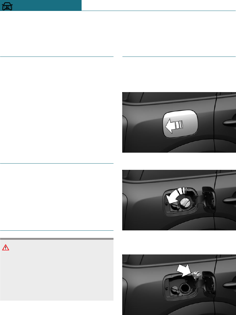
Refuelling
Vehicle equipment
This chapter describes all standard, country-
specific and special equipment available for
the model series. Therefore equipment
which is not installed in your vehicle, for
example on account of the optional equip-
ment selected or the country specification,
may also be described here. This also ap-
plies to safety-relevant functions and sys-
tems. Comply with the relevant laws and
regulations when using the corresponding
functions and systems.
General
Before refuelling, observe the notes on fuel
quality, see page 270.
On vehicles with diesel engines, the fuel
filler neck is designed for refuelling at die-
sel pumps.
Safety note
NOTE
If the range drops below 50 km, approxi-
mately 30 miles, the engine may no longer
be supplied with sufficient fuel. Engine
function is no longer ensured. There is a
danger of damage to property. Refuel in
good time.
Fuel tank cap
Opening
1. Briefly press the rear edge of the fuel
filler flap.
2. Turn the fuel tank cap anticlockwise.
3. Place the fuel tank cap in the holder on
the fuel filler flap.
Seite 268
MOBILITY Refuelling
268 Online Edition for Part no. 01402988211 - II/18
Draft
from BA-76
Closing
WARNING
The retaining strap of the fuel tank cap
may become trapped and crushed when
turning the cap to close it. It will then not
be possible to close the cap properly. Fuel
or fuel vapours can leak out. There is a
danger of injury or damage to property.
Make sure that the retaining strap does
not get trapped and crushed when closing
the cap.
1. Fit the tank cap and turn clockwise until
it is clearly heard to click into place.
2. Close the fuel filler flap.
Unlocking the fuel filler flap
manually
For example, if there is an electrical fault.
Have the fuel filler flap unlocked by a Serv-
ice Partner of the manufacturer or another
qualified Service Partner or a specialist
workshop.
Notes when refuelling
General
When refuelling, insert the filler nozzle
fully into the filler neck. Lifting the filler
nozzle during refuelling results in the
following:
–The fuel supply being cut off prema-
turely.
–Fuel vapour and fumes being recovered
less effectively.
The fuel tank is full when the filler nozzle
cuts out for the first time.
Comply with the safety regulations dis-
played at filling stations.
Safety note
NOTE
Fuels are poisonous and aggressive. Over-
filling the fuel tank can damage the fuel
system. If fuel comes into contact with
painted surfaces, it can damage them. This
pollutes the environment. There is a dan-
ger of damage to property. Avoid overfill-
ing.
Seite 269
Refuelling MOBILITY
269
Online Edition for Part no. 01402988211 - II/18
Draft
from BA-76
Fuel
Vehicle equipment
This chapter describes all standard, country-
specific and special equipment available for
the model series. Therefore equipment
which is not installed in your vehicle, for
example on account of the optional equip-
ment selected or the country specification,
may also be described here. This also ap-
plies to safety-relevant functions and sys-
tems. Comply with the relevant laws and
regulations when using the corresponding
functions and systems.
Fuel quality
General
Depending on the region, many filling sta-
tions sell fuel that is adapted to winter or
summer conditions. Fuel that is sold in win-
ter facilitates cold starting, for example.
Petrol
General
For optimal fuel consumption, the petrol
should be sulphur-free or low in sulphur
content.
Fuels labelled on the pump as containing
metal must not be used.
You can fill up with fuels with a maximum
proportion of ethanol of 25 %, for example
E10 or E25.
The engine has anti-knock control. This
means that different petrol grades can be
used.
Safety notes
NOTE
Even small quantities of the wrong fuel or
wrong fuel additives can damage the fuel
system and engine. In addition, the cata-
lytic converter will be permanently dam-
aged. There is a danger of damage to prop-
erty. Do not use the following fuel or
additives with petrol engines:
–Leaded petrol.
–Metallic additives, for example man-
ganese or iron.
After filling the wrong fuel, do not press
the start/stop button. Contact a Service
Partner of the manufacturer or another
qualified Service Partner or a specialist
workshop.
NOTE
Incorrect fuels can damage the fuel system
and engine. There is a danger of damage to
property. Do not refuel with fuel with a
higher proportion of ethanol than recom-
mended. Do not refuel with fuel containing
methanol, for example M5 to M100.
NOTE
Fuel below the specified minimum quality
can impact the engine function or lead to
engine damage. There is a danger of dam-
age to property. Do not refuel with petrol
below the specified minimum quality.
Petrol grade
Super, RON 95.
Seite 270
MOBILITY Fuel
270 Online Edition for Part no. 01402988211 - II/18
Draft
from BA-76
John Cooper Works:
Super Plus, RON 98.
Fill up this fuel so that the nominal perform-
ance data values and consumption is ach-
ieved.
Minimum grade
Unleaded petrol, RON 91.
John Cooper Works:
Super, RON 95.
Diesel
Safety note
NOTE
Even small quantities of the wrong fuel or
wrong fuel additives can damage the fuel
system and engine. There is a danger of
damage to property.
Note the following with diesel engines:
–Do not fill up with pure methyl ester.
–Only fill up with biodiesel with a
maximum of B7/7 % according to EN
590.
–Do not fill up with petrol.
–The vehicle manufacturer recom-
mends only using diesel additives
that have been classified as suitable.
After filling the wrong fuel, do not press
the start/stop button. Contact a Service
Partner of the manufacturer or another
qualified Service Partner or a specialist
workshop.
Diesel quality
The engine is designed to run on diesel fuel
to DIN EN 590 and ASTM D975.
SCR system with AdBlue in-
jection
Principle
The SCR system reduces nitrogen oxides in
the diesel exhaust emissions by injecting
the reducing agent AdBlue into the exhaust
stream. In the catalytic converter, this pro-
duces a chemical reaction that minimises
the nitrous oxides.
General
The vehicle has a tank which has to be top-
ped up.
To be able to establish drive-ready state in
the usual way, sufficient reduction agent
must be present.
Reduction agent can be topped up at any
time.
AdBlue reduction agents is a registered
trademark of the Verband der Automobilin-
dustrie e. V. (VDA).
Reduction agent is available at many serv-
ice stations.
Preferably add reduction agent at a pump
dispenser, see page 273.
AdBlue at low temperatures
Due to its physical properties, it is possible
that reduction agent has to be topped up
more frequently at temperatures below
-5 ℃/+23 ℉.
At temperatures below -11 ℃/+12 ℉, it
might only be possible to measure and dis-
play the fill level after a short journey.
At low temperatures, only top up with re-
duction agent directly before starting the
trip.
Seite 271
Fuel MOBILITY
271
Online Edition for Part no. 01402988211 - II/18
Draft
from BA-76
Display on the Control Display
Displaying range and top-up quantity
The range up to the latest possible top-up
time and the accurate top-up quantity are
shown on the Control Display.
Using the on-board monitor:
1. "My MINI"
2. "Vehicle status"
3. "AdBlue"
Displays in the instrument cluster
Tank display
The display in the instrument cluster in-
forms you of the remaining distance which
can be travelled with the current level.
Do not use up all of the displayed distance,
otherwise it might not be possible to re-es-
tablish drive-ready state after parking.
–White light: top up reduc-
tion agent at next opportu-
nity.
–Yellow light: not enough
reduction agent available.
Remaining range is shown
in instrument cluster. Im-
mediately top up reduction
agent, see page 272.
AdBlue on the minimum level
Remaining range is shown in
instrument cluster. Replenish
the reduction agent. Engine
continues to run, as long as it
is not stopped and all other op-
erating conditions are met, for
example, enough fuel.
System fault
If there is a system fault, a Check Control
message is displayed.
Visit the nearest Service Partner of the
manufacturer or another qualified Service
Partner or a specialist workshop.
AdBlue topping up
MINI recommends having the reducing
agent replenished by a Service Partner as
part of a regular maintenance schedule.
If you keep to this maintenance schedule, a
single top-up is generally required between
the maintenance appointments.
Under certain circumstances, for example
due to particularly dynamic driving style or
operating the vehicle with a trailer, topping
up between maintenance appointments
more than once may be necessary.
As soon as the tank display is shown in the
instrument cluster, have the reduction
agent topped up, to prevent drive-ready
state from no longer being able to be estab-
lished.
Topping up AdBlue yourself
Safety notes
WARNING
Service products, for example oils, greases,
coolants and fuels, can contain substances
that are harmful to health. There is a dan-
ger of injury or even death. Comply with
the instructions on the containers. Do not
allow service products to come into con-
tact with clothing, skin or eyes. Do not
pour service products into other bottles.
Keep service products out of the reach of
children.
Seite 272
MOBILITY Fuel
272 Online Edition for Part no. 01402988211 - II/18
Draft
from BA-76
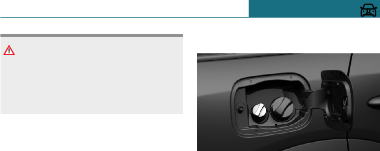
NOTE
The constituents of reduction agent are
highly aggressive. There is a danger of
damage to property. Avoid contact of re-
duction agent with surfaces of the vehicle.
Suitable AdBlue
AdBlue of standard ISO 22241-1
At many service stations, reduction agent is
available at a special pump dispenser. Pref-
erably add reduction agent at a pump dis-
penser.
If no pump dispenser is available, reduction
agent can be replenished from a container.
Reduction agent is available in various con-
tainers. Preferably, use the special bottle
recommended by MINI. With this bottle and
its special adapter, reduction agent can be
topped up conveniently.
Top up quantity
When the reserve indicator starts, top up at
least 5 litres, approx. 1.3 gal.
Indicating top-up quantity
Precise top-up quantity is shown on Control
Display.
Using the on-board monitor:
1. "My MINI"
2. "Vehicle status"
3. "AdBlue"
Reduction agent tank
The fuel tank cap for the reduction agent is
located next to the fuel tank cap for the fuel
tank.
Replenishing reduction agent at the
pump dispenser
General
When refuelling, insert the filler nozzle
fully into the filler neck. Lifting the filler
nozzle during refuelling results in the
following:
–The fuel supply being cut off prema-
turely.
–Overflow of reducing agent.
The tank for the reducing agent is full when
the filler nozzle cuts out for the first time.
Comply with the safety regulations dis-
played at filling stations.
Seite 273
Fuel MOBILITY
273
Online Edition for Part no. 01402988211 - II/18
Draft
from BA-76
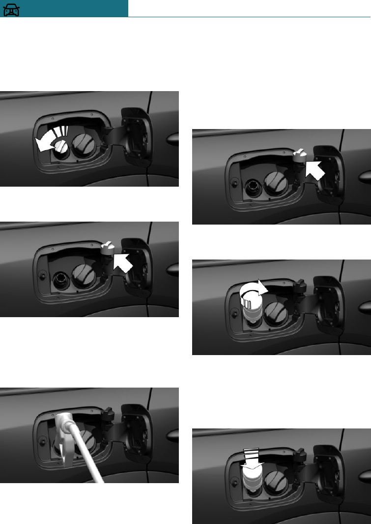
Adding reducing agent
1. Open fuel filler flap, see page 268.
2. Turn the reduction agent tank cap anti-
clockwise and remove.
3. Place the fuel tank cap in the holder on
the fuel filler flap.
4. Use the pump nozzle to replenish at
least the recommended top-up quantity,
see page 273.
The tank is full when the filler nozzle
cuts out for the first time.
5. Put fuel tank cap back on and turn
clockwise.
6. Close the fuel filler flap.
Replenishing reduction agent with a
bottle
1. Open fuel filler flap, see page 268.
2. Turn the reduction agent tank cap anti-
clockwise and remove.
3. Place the fuel tank cap in the holder on
the fuel filler flap.
4. Attach the bottle and turn clockwise un-
til it stops.
5. Push the bottle down.
The tank in the vehicle is filled.
The tank in the vehicle is filled when
the level in the bottle does not change
any more. It is not possible to overfill.
Seite 274
MOBILITY Fuel
274 Online Edition for Part no. 01402988211 - II/18
Draft
from BA-76
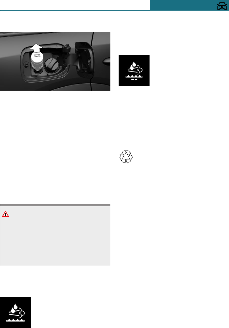
6. Pull back bottle and unscrew.
7. Put fuel tank cap back on and turn
clockwise.
8. Close the fuel filler flap.
Filling with an incorrect fluid
General
A Check Control message is displayed if the
tank has been filled with the wrong fluid.
If the wrong type of liquid has been added,
contact a Service Partner of the manufac-
turer or another qualified Service Partner or
a specialist workshop.
Safety note
WARNING
After filling with an incorrect liquid, the
system may heat up and catch fire. There
is a danger of fire and injury. Only fill with
liquids that are intended for the tank. Do
not start the engine after filling with an
incorrect liquid.
After filling reduction agent
Tank display
After topping up, the tank dis-
play continues to be shown
with remaining range.
Drive-ready state can be es-
tablished.
After a journey of several minutes, the re-
serve range display goes out.
AdBlue on the minimum level
After filling up, the display
continues to be shown.
Drive-ready state can only be
established when the display
is no longer illuminated.
1. Press the start/stop button.
Display is no longer illuminated after ap-
proximately 1 minute.
2. Press the start/stop button and establish
drive-ready state.
Disposing of bottles
Dispose of bottles for AdBlue at a
Service Partner of the manufacturer
or another qualified Service Partner
or a specialist workshop or hand them into
an authorised collecting point.
Only dispose of bottles with normal waste if
the local regulations permit this.
Seite 275
Fuel MOBILITY
275
Online Edition for Part no. 01402988211 - II/18
Draft
from BA-76
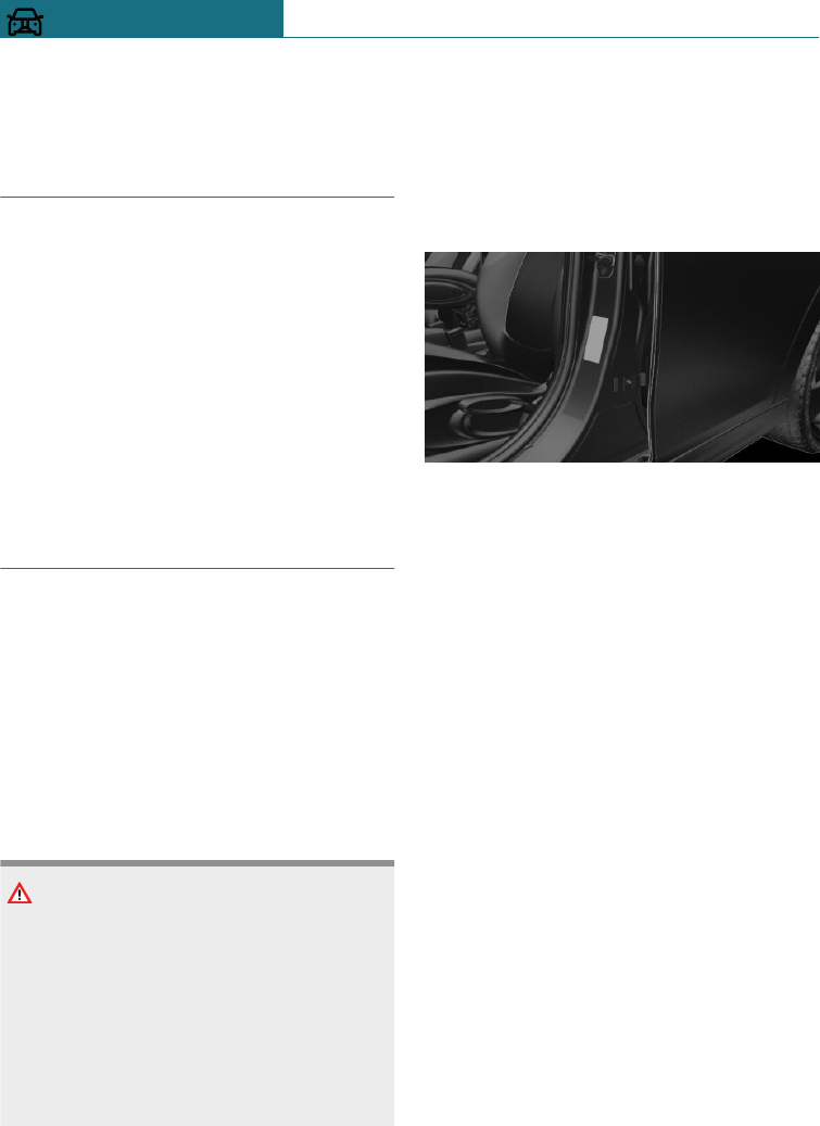
Wheels and tyres
Vehicle equipment
This chapter describes all standard, country-
specific and special equipment available for
the model series. Therefore equipment
which is not installed in your vehicle, for
example on account of the optional equip-
ment selected or the country specification,
may also be described here. This also ap-
plies to safety-relevant functions and sys-
tems. Comply with the relevant laws and
regulations when using the corresponding
functions and systems.
Tyre inflation pressure
General
A tyre's condition and inflation pressure in-
fluence the following:
–Lifetime of the tyre.
–Driving safety.
–Driving comfort.
–Fuel consumption.
Safety note
WARNING
A tyre with too little or no tyre inflation
pressure can heat up significantly and sus-
tain damage. Driving properties, for exam-
ple steering and braking, will be impaired
as a result. There is a danger of accidents.
Check the tyre inflation pressure regularly
and adjust as necessary, for example twice
a month or before any long journey.
Tyre inflation pressure information
On the door pillar
The tyre inflation pressures are shown on
the door pillar of the driver's door.
The tyre inflation pressure data applies to
the tyre sizes and recommended tyre makes
which have been classified by the vehicle
manufacturer as suitable for the respective
vehicle type.
If the tyre's speed code cannot be found,
then the tyre inflation pressure for the cor-
responding tyre size applies.
The tyre inflation pressures stated for the
respective load conditions will apply, in ac-
cordance with the vehicle's actual load con-
dition. Example: for a partially loaded vehi-
cle, the optimum tyre inflation pressure is
the one stated for a partially loaded vehicle.
More information regarding wheels and
tyres can be obtained from a Service Part-
ner of the manufacturer or another qualified
Service Partner or a specialist workshop.
Seite 276
MOBILITY Wheels and tyres
276 Online Edition for Part no. 01402988211 - II/18
Draft
from BA-76
For Australia/New Zealand
WARNING
The inflation pressures on the tyre label
are applicable only for tyres explicitly
mentioned on the label. Inflation pressures
for tyres that may be covered by the label
– by size, speed category and load rating/
load index – but not explicitly mentioned
on the label may be different. Please ob-
tain adequate inflation pressures in ac-
cordance with the tyre manufacturer's
specifications at your tyre dealer.
Checking the tyre inflation
pressure
General
Tyres heat up while driving. The tyre infla-
tion pressure increases with the tempera-
ture of the tyre.
Tyres have a natural, uniform loss of tyre in-
flation pressure.
Inflating devices can display a pressure as
much as 0.1 bar too low.
Checking using tyre inflation pressure
inscriptions on the door pillar
The tyre inflation pressure inscriptions on
the tyre inflation pressure sign on the door
pillar only relate to cold tyres or tyres at the
same temperature as the ambient tempera-
ture.
Only check the tyre inflation pressures
when the tyres are cold, i.e.:
–A driving distance of max. 2 km,
1.25 miles has not been exceeded.
–If the vehicle has not moved again for at
least 2 hours after a journey.
1. Determine the intended tyre inflation
pressures for the tyres when fitted to
the vehicle, see page 276.
2. Check the tyre inflation pressure in all
four tyres, using a pressure gauge,
for example.
3. Correct the tyre inflation pressure if the
current tyre inflation pressure value de-
viates from the specified value.
4. Check whether all valve caps are
screwed onto the tyre valves.
After adjusting the tyre inflation
pressure
For the runflat indicator RPA: reinitialise
the runflat indicator RPA.
For the Tyre Pressure Monitor TPM: reset
the Tyre Pressure Monitor TPM.
Not for Australia/New Zealand:
Checking the tyre inflation pressure of
the emergency wheel
Additionally, regularly check the tyre infla-
tion pressure of the emergency wheel in the
boot and correct the pressure if necessary.
Speed code
Q = up to 160 km/h/100 mph
R = up to 170 km/h/106 mph
S = up to 180 km/h/112 mph
T = up to 190 km/h/118 mph
H = up to 210 km/h/131 mph
V = up to 240 km/h/150 mph
W = up to 270 km/h/167 mph
Y = up to 300 km/h/186 mph
Seite 277
Wheels and tyres MOBILITY
277
Online Edition for Part no. 01402988211 - II/18
Draft
from BA-76
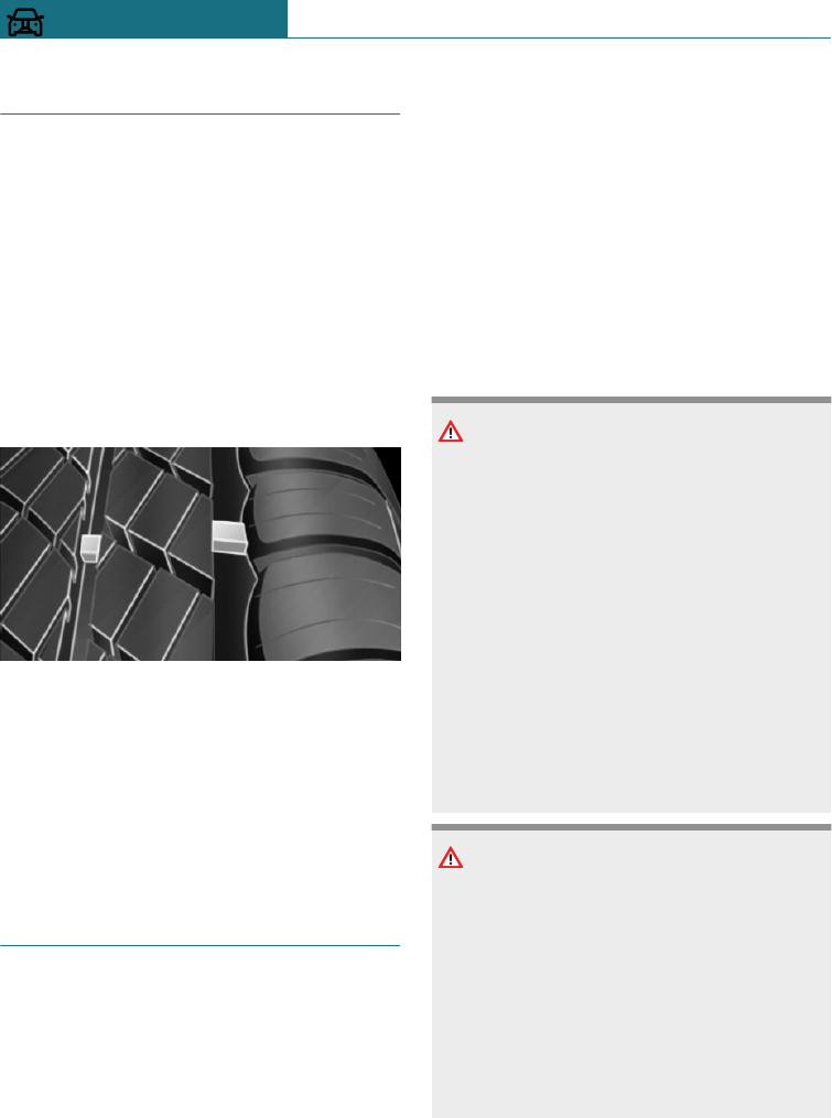
Tyre tread
Summer tyres
The tyre tread depth should not be less than
3 mm, 0.12 in, otherwise there is a high risk
of aquaplaning.
Winter tyres
The tyre tread depth should not be less than
4 mm, 0.16 in, otherwise the vehicle's suita-
bility for winter use is restricted.
Minimum tread depth
Wear indicators are distributed across the
tyre circumference and have the legally pre-
scribed minimum height of 1.6 mm, approxi-
mately 1/16 in.
The positions of the wear displays are iden-
tified on the tyre's side wall by TWI, Tread
Wear Indicator.
Tyre damage
General
Inspect tyres regularly for damage, the pres-
ence of foreign bodies and wear.
Vehicle behaviour that may indicate tyre
damage or other faults:
–Unusual vibrations.
–Unusual tyre or running noises.
–Unusual vehicle response, such as pro-
nounced pulling to the left or right.
Damage can be caused by the following sit-
uations, for example:
–Driving over kerbs.
–Road damage.
–Tyre inflation pressure insufficient.
–Vehicle overloading.
–Incorrect tyre storage.
Safety notes
WARNING
If the tyres are damaged, the tyre inflation
pressure may be reduced which in turn
could cause you to lose control of the vehi-
cle. There is a danger of accidents. If you
suspect tyre damage while you are driving,
immediately reduce speed and bring the
vehicle to a stop. Have the wheels and
tyres checked. To do so, carefully drive to
a Service Partner of the manufacturer or
another qualified Service Partner or a spe-
cialist workshop. If necessary, have the ve-
hicle towed or transported there. Do not
repair damaged tyres, have them renewed
instead.
WARNING
Tyres can become damaged by running
over obstacles, for example kerbs or road
damage, at high speed. Larger wheels have
a smaller tyre cross-section. The smaller
the tyre cross-section, the higher the risk
of tyre damage. There is a danger of acci-
dents and damage to property. If possible,
drive around obstacles, or drive over them
slowly and carefully.
Seite 278
MOBILITY Wheels and tyres
278 Online Edition for Part no. 01402988211 - II/18
Draft
from BA-76
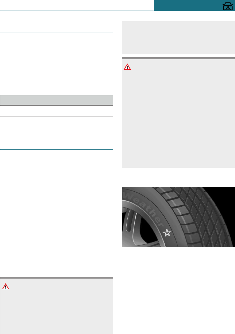
Age of tyres
Recommendation
Irrespective of the tyre tread depth, change
the tyres after 6 years at the latest.
Date of manufacture
The date of manufacture of the tyre is indi-
cated on the tyre sidewall.
Designation Date of manufacture
DOT … 0118 1st week of 2018
Replacement of wheels and
tyres
Fitting and balancing
Have the wheel fitted and balanced by a
Service Partner of the manufacturer or an-
other qualified Service Partner or a special-
ist workshop.
Wheel/tyre combination
General
Information on the correct wheel/tyre com-
bination and rim designs for the vehicle can
be obtained from a Service Partner of the
manufacturer or another qualified Service
Partner or a specialist workshop.
Safety notes
WARNING
Wheels and tyres that are not suitable for
your vehicle can damage parts of the vehi-
cle. For example they could come into con-
tact with the bodywork on account of their
dimensional tolerances, despite having the
same nominal size. There is a danger of ac-
cidents. The manufacturer of the vehicle
recommends using wheels and tyres that
have been categorised as suitable for the
respective vehicle type.
WARNING
Incorrect wheel/tyre combinations impair
the vehicle's driving properties and inter-
fere with the proper functioning of various
systems, such as ABS or DSC. There is a
danger of accidents. To maintain good ve-
hicle handling, always fit tyres of the same
make and tread pattern to all wheels. The
manufacturer of the vehicle recommends
using wheels and tyres that have been cat-
egorised as suitable for the respective ve-
hicle type. After a tyre has been damaged,
refit the same wheel/tyre combination as
the original.
Recommended makes of tyre
Certain makes of tyre are recommended by
the manufacturer of the vehicle for each
tyre size. The tyre brands can be identified
by a star on the side wall of the tyre.
New tyres
Due to the manufacturing process, new
tyres do not achieve their full road grip im-
mediately.
Drive moderately for the first 300 km, ap-
proximately 200 miles.
Seite 279
Wheels and tyres MOBILITY
279
Online Edition for Part no. 01402988211 - II/18
Draft
from BA-76
Retreaded tyres
WARNING
Retreaded tyres may have different tyre
carcasses. Their durability may be reduced
with increasing age. There is a danger of
accidents. Do not use retreaded tyres.
The manufacturer of your vehicle advises
against the use of retreaded tyres.
Winter tyres
Winter tyres are recommended if driving in
winter conditions.
Although so-called all-season tyres with an
M+S label have better winter characteristics
than summer tyres, they do not normally
match the performance of winter tyres.
Maximum speed of winter tyres
If the vehicle is capable of maximum speeds
higher than the speed permitted for the
winter tyres, display an indicating label
stating the maximum permitted speed in the
driver's field of view. The indicating label is
available from a Service Partner of the man-
ufacturer or another qualified Service Part-
ner or a specialist workshop.
If winter tyres are fitted, observe and do not
exceed the respectively permitted maximum
speed.
Run-flat tyres
For your own safety, when using run-flat
tyres, do not mix with other types of tyre.
There is no spare wheel available in the
event of a breakdown. Additional informa-
tion is available from a Service Partner of
the manufacturer or another qualified Serv-
ice Partner or a specialist workshop.
Interchanging front and rear
wheels
Different tyre tread wear patterns occur on
the wheels of the front and rear axles, de-
pending on the individual operating condi-
tions. To achieve even wear, the tyres can
be rotated in pairs between the axles. Addi-
tional information is available from a Serv-
ice Partner of the manufacturer or another
qualified Service Partner or a specialist
workshop. After changing, check the tyre
inflation pressure and adjust if necessary.
Storing tyres
Air pressure
Do not exceed the maximum tyre inflation
pressure indicated on the tyre's side wall.
Tyre storage
Store wheels and tyres in a cool, dry and
dark place when not in use.
Protect the tyres against contamination
from oil, grease and solvents.
Do not leave the tyres in plastic bags.
Remove dirt from the wheels or tyres.
Run-flat tyres
Principle
In the event of a complete loss of tyre infla-
tion pressure, run-flat tyres enable you to
continue driving, with certain restrictions.
General
The wheels are fitted with tyres which are
self-supporting to a limited degree.
The reinforced side wall means that the tyre
keeps the vehicle mobile to a degree even if
tyre inflation pressure has been lost.
Seite 280
MOBILITY Wheels and tyres
280 Online Edition for Part no. 01402988211 - II/18
Draft
from BA-76
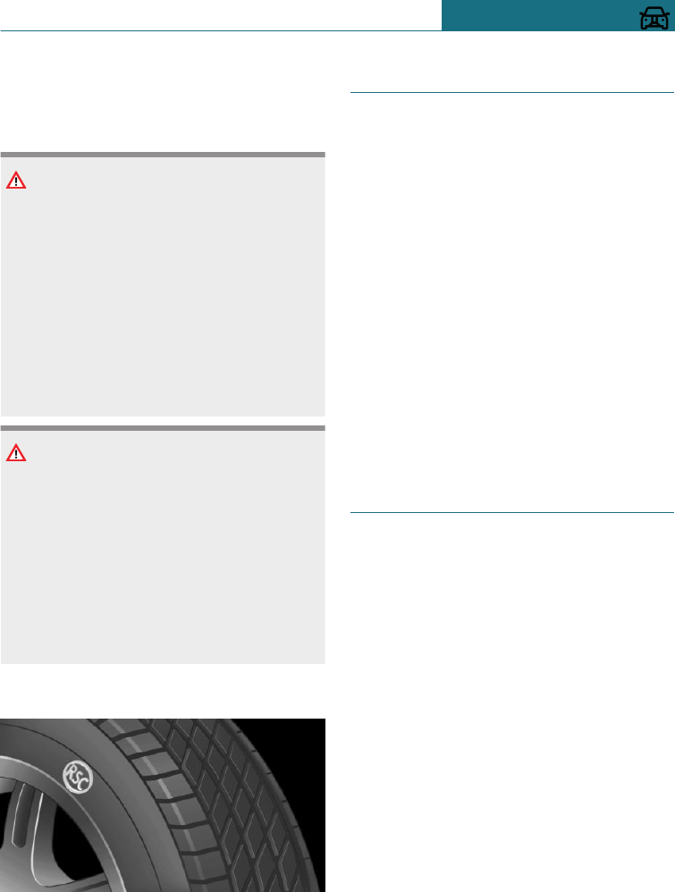
Observe the notes on continuing to drive
with a flat tyre.
Safety notes
WARNING
A run-flat tyre which has low tyre inflation
pressure or no tyre inflation pressure at all
will change the vehicle's handling charac-
teristics, for example there may be re-
duced directional stability when braking,
longer braking distances and different
self-steering characteristics. There is a
danger of accidents.
Drive with care and do not exceed a speed
of 80 km/h, 50 mph.
WARNING
Continuing to drive with a flat tyre can re-
sult in heavy trailers starting to slalom.
There is a danger of accidents or damage
to property. When driving with a trailer
and a flat tyre, do not exceed the speed of
60 km/h, approximately 35 mph. In case of
swaying or fishtailing motions, brake im-
mediately and make the necessary steer-
ing corrections as carefully as possible.
Label
The tyres are identified on the tyre's side
wall by RSC Runflat System Component.
Remedying flat tyres
Safety measures
–Park the vehicle on a solid surface and
as far away from moving traffic as possi-
ble.
–Switch on the hazard warning lights.
–Apply the parking brake to prevent the
vehicle rolling away.
–Engage the steering wheel lock with the
wheels in the straight-ahead position.
–Have all vehicle occupants get out of the
vehicle and guide them out of the dan-
ger area, for example behind the crash
barrier.
–Set up the warning triangle an appropri-
ate distance away.
Mobility System
Principle
With the Mobility System, minor tyre dam-
age can be quickly sealed, to allow you to
drive on. For this purpose, liquid sealant is
pumped into the tyres which encloses the
damage from the inside when it hardens.
General
–Please observe the notes on the applica-
tion of the Mobility System which are
on the compressor and the sealant con-
tainer.
–Applying the Mobility System can be in-
effective for tyre damage larger than ap-
proximately 4 mm.
–Contact a Service Partner of the manu-
facturer or another qualified Service
Partner or a specialist workshop if you
are unable to put the tyre back in opera-
tion.
Seite 281
Wheels and tyres MOBILITY
281
Online Edition for Part no. 01402988211 - II/18
Draft
from BA-76

–If possible, foreign matter that has pene-
trated the tyre should remain inside the
tyre. Only remove foreign objects if they
are visibly protruding from the tyre.
–Remove the speed limit sticker from the
sealant container and attach to the
steering wheel.
–Using sealants can damage the TPM
wheel electronics. In this case, have the
TPM wheel electronics replaced at the
next opportunity.
–The compressor can be used to check
the tyre inflation pressure.
Overview
Storage
The Mobility System is located in a bag at
the right-hand side panel in the boot.
Sealant container
–Sealant container, arrow 1.
–Filler hose, arrow 2.
Note the use-by date on the sealant con-
tainer.
Compressor
1Unlocking sealant container
2Sealant container holder
3Tyre inflation pressure indicator
4Reduce tyre inflation pressure button
5On/Off button
6Compressor
7Plug/cable for socket
8Connecting hose
Safety measures
–Park the vehicle on a solid surface and
as far away from moving traffic as possi-
ble.
–Switch on the hazard warning lights.
–Apply the parking brake to prevent the
vehicle rolling away.
–Engage the steering wheel lock with the
wheels in the straight-ahead position.
–Have all vehicle occupants get out of the
vehicle and guide them out of the dan-
ger area, for example behind the crash
barrier.
–Set up the warning triangle an appropri-
ate distance away.
Seite 282
MOBILITY Wheels and tyres
282 Online Edition for Part no. 01402988211 - II/18
Draft
from BA-76
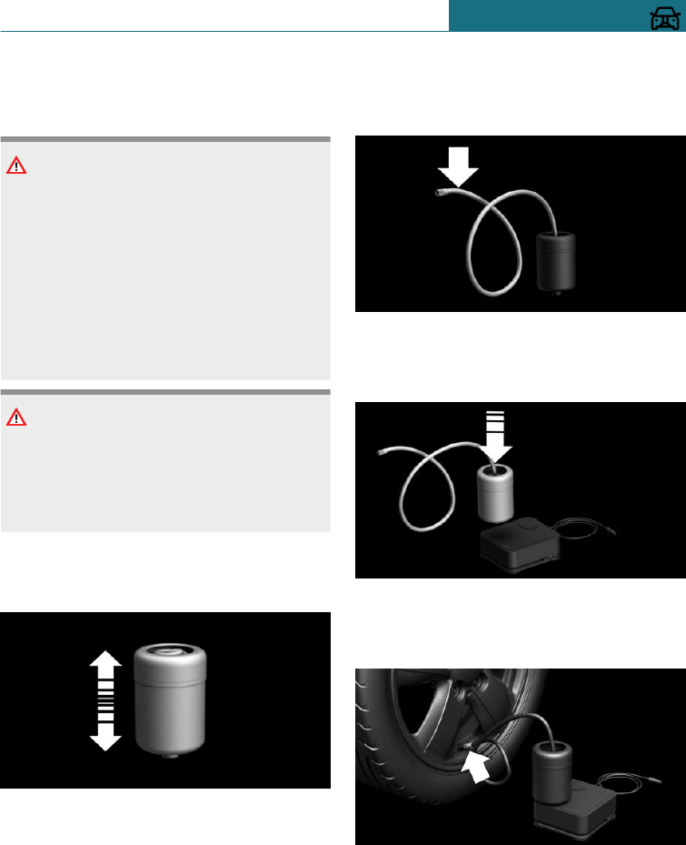
Filling with sealing compound
Safety notes
DANGER
A blocked exhaust pipe or inadequate ven-
tilation can allow harmful exhaust fumes
to penetrate the vehicle. The exhaust
fumes contain pollutants which are colour-
less and odourless. In enclosed spaces, the
exhaust fumes can also build up outside
the vehicle. There is a danger of fatal in-
jury. Keep the exhaust pipe clear and en-
sure sufficient ventilation.
NOTE
The compressor can overheat if operated
for too long. There is a danger of damage
to property. Do not let the compressor run
for longer than 10 minutes.
Filling
1. Shake the sealant container.
2. Pull filler hose completely from the
cover of the sealant container. Do not
kink the hose.
3. Push the sealant container into the
bracket on the compressor housing, un-
til it audibly engages.
4. Screw the filler hose of the sealant con-
tainer onto the tyre valve of the faulty
wheel.
Seite 283
Wheels and tyres MOBILITY
283
Online Edition for Part no. 01402988211 - II/18
Draft
from BA-76
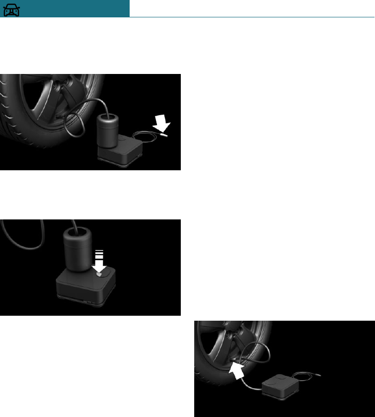
5. Insert the plug into the socket in the ve-
hicle interior while the compressor is
switched off.
6. Switch on the compressor when the ig-
nition is switched on or the engine is
running.
Let the compressor run for approximately
10 minutes to fill the sealing compound and
achieve a tyre inflation pressure of approxi-
mately 2.5 bar.
The tyre inflation pressure may rise to ap-
proximately 5 bar during the filling process
of the sealing compound. Do not switch off
the compressor during this step.
Checking and adjusting the tyre
inflation pressure
Checking
1. Switch off compressor.
2. Read off the tyre inflation pressure as
shown on the tyre pressure indicator.
To be able to continue the journey, a tyre
inflation pressure of at least 2 bar must be
reached.
Removing and storing the sealant
container
1. Unscrew the filler hose of the sealant
container from the tyre valve.
2. Press the red unlocking device.
3. Remove the sealant container from the
compressor.
4. Pack and store the sealant container to
avoid soiling the boot.
Minimum tyre inflation pressure is not
reached
1. Unplug the connector from the socket in
the vehicle interior.
2. Drive forwards and backwards by 10 m,
approximately 400 inches, to distribute
the sealant in the tyre.
3. Screw the connecting hose of the com-
pressor directly onto the tyre valve.
Seite 284
MOBILITY Wheels and tyres
284 Online Edition for Part no. 01402988211 - II/18
Draft
from BA-76
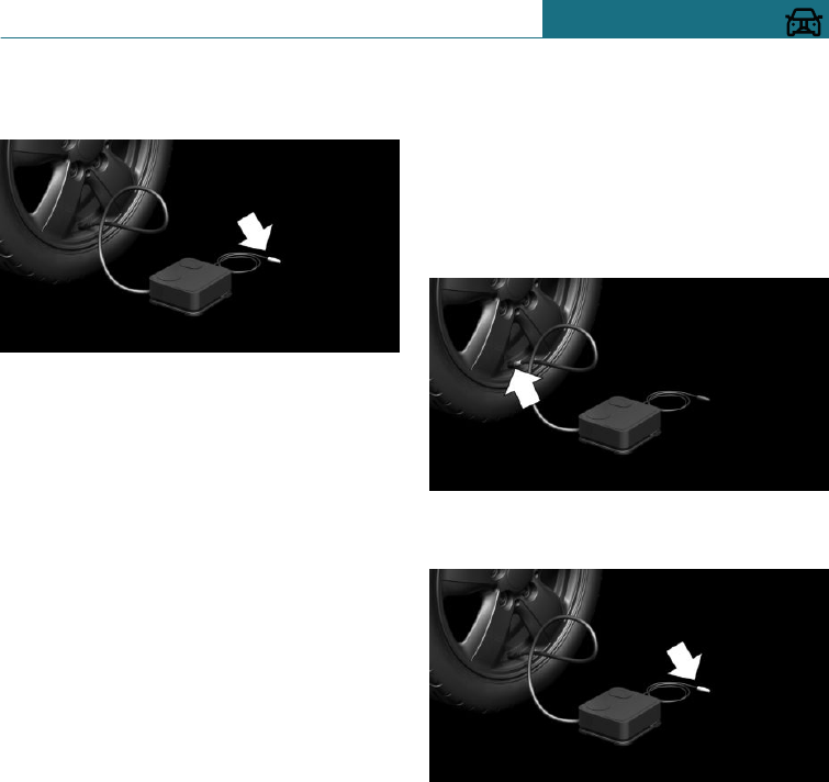
4. Insert the plug into the socket in the ve-
hicle interior.
5. Switch on the compressor when the ig-
nition is switched on or the engine is
running.
If the tyre inflation pressure of at least
2 bar is not reached, contact a Service
Partner of the manufacturer or a quali-
fied Service Partner or a specialist work-
shop.
If the tyre inflation pressure of at least
2 bar is reached, see Minimum inflation
pressure is reached.
6. Unscrew the connecting hose of the
compressor from the tyre valve.
7. Unplug the connector from the socket in
the vehicle interior.
8. Store Mobility System in the vehicle.
Minimum tyre inflation pressure is
reached
1. Unscrew the connecting hose of the
compressor from the tyre valve.
2. Unplug the connector from the socket in
the vehicle interior.
3. Store Mobility System in the vehicle.
4. Immediately drive for approximately
10 km/5 mi to evenly distribute the
sealing compound in the tyre.
Do not exceed a speed of
80 km/h/50 mph.
If possible, do not drive slower than
20 km/h/12 mph.
To adjust
1. Stop in a suitable area.
2. Screw the connecting hose of the com-
pressor directly onto the tyre valve.
3. Insert the plug into the socket in the ve-
hicle interior.
4. Correct tyre inflation pressure to at least
2.0 bar.
–To increase the tyre inflation pres-
sure: switch on the compressor with
the engine running or the ignition
switched on.
–To reduce tyre inflation pressure:
press the button on the compressor.
5. Unscrew the connecting hose of the
compressor from the tyre valve.
6. Unplug the connector from the socket in
the vehicle interior.
7. Store Mobility System in the vehicle.
Seite 285
Wheels and tyres MOBILITY
285
Online Edition for Part no. 01402988211 - II/18
Draft
from BA-76
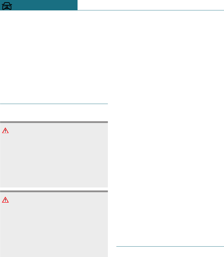
Resuming with journey
Do not exceed maximum permitted speed of
80 km/h, approximately 50 mph.
Reinitialise runflat indicator, see page 157.
Reset Tyre Pressure Monitor, see page 152.
Have the punctured tyre and the sealant
container of the Mobility System replaced
as soon as possible.
Snow chains
Safety notes
WARNING
If snow chains are installed on unsuitable
tyres, the snow chains can come in contact
with vehicle parts. There is a danger of ac-
cidents or damage to property. Only fit the
snow chains on tyres that the manufac-
turer has authorised as suitable for snow
chains.
WARNING
Insufficiently tight snow chains can dam-
age tyres and vehicle components. There
is a danger of accidents or damage to prop-
erty. Ensure that the snow chains are al-
ways adequately taut. Re-tighten them if
necessary in accordance with the snow
chain manufacturer's instructions.
Fine-link snow chains
The manufacturer of your vehicle recom-
mends using fine-link snow chains. Certain
fine-link snow chains have been tested,
found safe for use in traffic, and categorised
as suitable by the manufacturer of the vehi-
cle.
Information regarding suitable snow chains
is available from a Service Partner of the
manufacturer or another qualified Service
Partner or a specialist workshop.
Using
Snow chains may only be used in pairs on
the front wheels with tyres of the following
sizes:
–205/65 R 16.
–205/60 R 17.
John Cooper Works:
205/60 R 17
Observe the snow chain manufacturer's in-
structions.
Do not initialise the runflat indicator RPA
with snow chains fitted, as it may give in-
correct readings.
Do not reset the Tyre Pressure Monitor
TPM with snow chains fitted, as it may give
incorrect readings.
When driving with snow chains, activate
Dynamic Traction Control DTC briefly if
necessary.
Maximum speed with snow chains
When snow chains are fitted, do not exceed
50 km/h, 30 mph.
Wheel change
General
For run-flat tyres or when using a flat tyre
kit, it is not always necessary to change a
wheel immediately if tyre inflation pressure
is lost due to a flat tyre.
If required, the tools for changing wheels
are available as optional accessories from a
Service Partner of the manufacturer, an-
other qualified Service Partner or a special-
ist workshop.
Seite 286
MOBILITY Wheels and tyres
286 Online Edition for Part no. 01402988211 - II/18
Draft
from BA-76
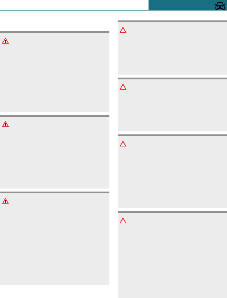
Safety notes
DANGER
The jack is only intended for raising the
vehicle briefly during a wheel change.
Even if the safety measures are complied
with, there is a risk of the raised vehicle
falling over due to the jack slipping. There
is a danger of injury or even death. If the
vehicle is raised with the jack, do not lie
underneath the vehicle and do not start
the engine.
DANGER
Supports such as wooden blocks under the
vehicle jack can prevent it from achieving
its load capacity due to the restricted
height. The load capacity of the wooden
blocks may be exceeded, causing the vehi-
cle to tip over. There is a danger of injury
or even death. Do not place supports under
the vehicle jack.
WARNING
The jack, issued by the vehicle manufac-
turer, is provided in order to perform a
wheel change in the event of a breakdown.
The jack is not designed for frequent use;
for example, changing from summer to
winter tyres. Using the jack frequently
may cause it to become jammed or dam-
aged. There is a danger of injury and dam-
age to property. Only use the jack to
change an emergency wheel or a spare
wheel in the event of a flat tyre.
WARNING
On soft, uneven or slippery ground, for ex-
ample, snow, ice, tiles or similar, the jack
may slip. There is a danger of injury. Per-
form the wheel change on a level, firm and
non-slip surface if at all possible.
WARNING
The jack is only optimised for raising the
vehicle and for use with the jacking points
on the vehicle. There is a danger of injury.
Do not lift another vehicle or other items
with the jack.
WARNING
If the jack has not been guided into the
jacking point provided, the vehicle might
be damaged when the jack is extended, or
the jack could slip. There is a danger of in-
jury or damage to property. When extend-
ing, make sure that the jack is guided into
the jacking point adjacent to the wheel-
house.
WARNING
A vehicle raised with a jack can fall from
the jack if lateral forces are applied. There
is a danger of injury and damage to prop-
erty. If the vehicle is raised, do not apply
any lateral forces to the vehicle or pull the
vehicle with sudden movements. Have any
wheel that is jammed removed by a Serv-
ice Partner of the manufacturer or another
qualified Service Partner or a specialist
workshop.
Seite 287
Wheels and tyres MOBILITY
287
Online Edition for Part no. 01402988211 - II/18
Draft
from BA-76
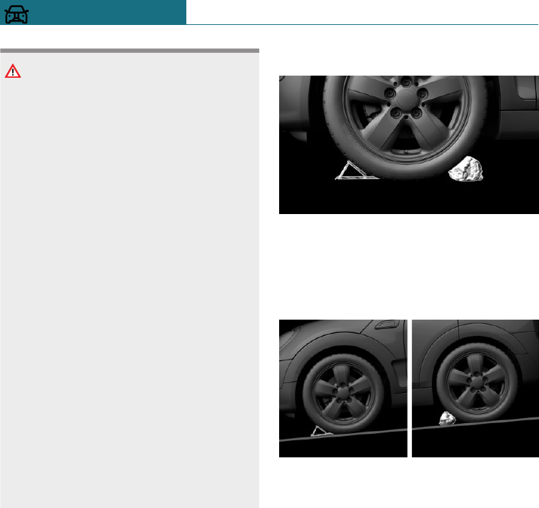
Vehicle jack: Australian/New Zea-
land standard AS/NZS 2693
2007 – "Vehicle jacks" contains the
following warning note which MINI
hereby adopts: "... no person should place
any portion of their body under a vehicle
that is supported by a jack"
The jack supplied with your vehicle should
not be used for any purpose other than
wheel changing and should never be used
in conjunction with a vehicle support
stand. Raising the vehicle for the purpose
of inspection should only be performed in
a controlled workshop environment on a
hoist by trained personnel.
The following warning instructions from
standard AS/NZS 2693:2007 are repeated
here: the jack should be used on level firm
ground wherever possible. It is recommen-
ded that the wheels of the vehicle be
chocked, and that no person should remain
in a vehicle that is being jacked.
The jack of your MINI is maintenance-
free.
Please observe the information marked on
the jack.
Protecting the vehicle against
rolling
General
The vehicle manufacturer recommends that
the vehicle should additionally be protected
against rolling away during a wheel change.
On a level surface
Place chocks or other suitable objects in
front of and behind the wheel directly oppo-
site to the one being changed.
On a slight downhill slope
If it is necessary to change a wheel on a
slight downhill slope, place chocks and
other suitable objects, for example stones,
under the wheels of the front and rear axles
in the opposite direction to the direction of
roll.
Thiefproof wheel studs
Principle
The wheel locking bolts have a special cod-
ing. The blots can only be released with the
adapter that matches the coding.
Overview
The adapter of the thiefproof wheel studs is
in the on-board tool kit, see page 305.
Seite 288
MOBILITY Wheels and tyres
288 Online Edition for Part no. 01402988211 - II/18
Draft
from BA-76
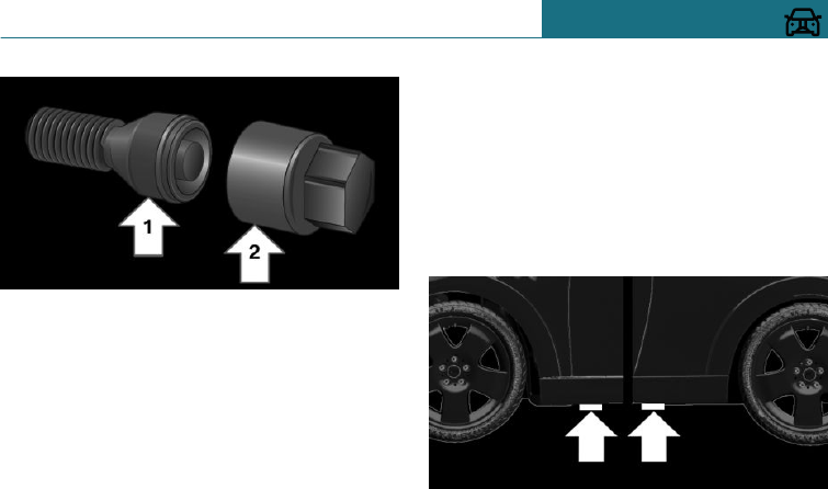
–Wheel stud, arrow 1.
–Adapter, arrow 2.
Unscrewing
1. Place the adapter on the wheel stud.
2. Unscrew the wheel stud.
3. After unscrewing the wheel stud, re-
move the adapter again.
Screwing on
1. Place the adapter on the wheel stud. If
necessary, turn the adapter until it fits
on the wheel stud.
2. Screw on the wheel stud. The tightening
torque is 140 Nm.
3. After screwing on the wheel stud, re-
move the adapter again and stow it.
Preparing the vehicle
–Park the vehicle on firm and non-slip
ground at a safe distance from traffic.
–Switch on the hazard warning lights.
–Apply the parking brake.
–Engage a gear or select selector lever
position P.
–As soon as the traffic permits, have all
vehicle occupants get out of the vehicle
and guide them out of the danger area,
for example behind the crash barrier.
–Depending on the equipment, take the
wheel change tools and, if necessary, the
emergency wheel out of the vehicle.
–If applicable, set up warning triangle or
flashing light at the correct distance.
–Additionally protect the vehicle against
rolling away.
–Undo the wheel studs by half a turn.
Jack mounting points
The jacking points are at the positions
marked.
Seite 289
Wheels and tyres MOBILITY
289
Online Edition for Part no. 01402988211 - II/18
Draft
from BA-76
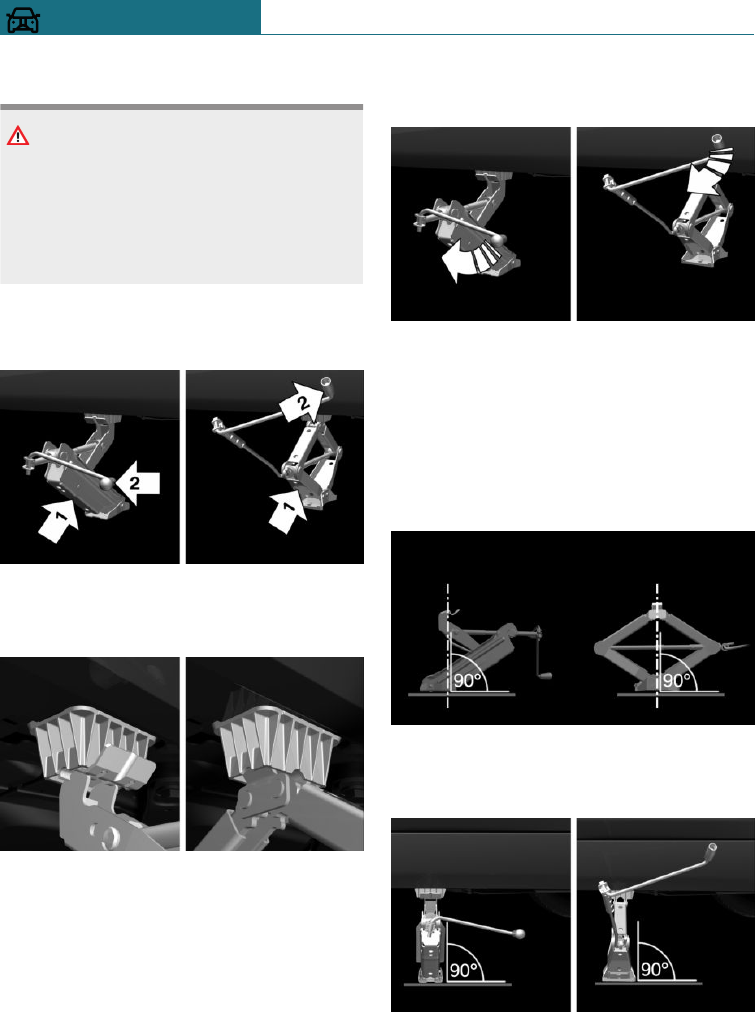
Raising vehicle
WARNING
Your hands or fingers could get trapped
when using the jack. There is a danger of
injury. Keep your hands in the described
position when using the jack, and do not
change this position.
1. Hold the jack with one hand, arrow 1,
and grasp the jack crank or lever with
your other hand, arrow 2.
2. Guide the jack into the rectangular re-
cess of the jacking point closest to the
wheel to be changed.
3. Turn the jack crank or lever clockwise
to extend the jack.
4. Remove your hand from the jack as soon
as the jack is under load and continue to
turn the jack crank or lever with one
hand.
5. Make sure that the base of the vehicle
jack is extended perpendicular to and at
right angles underneath the jacking
point.
6. Make sure that the base of the jack is
extended perpendicular to and at right
angles below the jacking point.
7. Raise by cranking until the jack is sup-
ported on the ground with its entire sur-
Seite 290
MOBILITY Wheels and tyres
290 Online Edition for Part no. 01402988211 - II/18
Draft
from BA-76
face and the wheel in question is at
most 3 cm, 1.2 inches off the ground.
Fitting a wheel
Only fit one emergency wheel at most, as
required.
1. Unscrew the wheel studs.
2. Remove the wheel.
3. Put on the new wheel or emergency
wheel and tighten at least two wheel
studs crosswise until finger-tight.
If non-original light alloy wheels not
from the vehicle manufacturer are fitted,
the wheel studs belonging to the wheels
may also have to be used.
4. Tighten the remaining wheel studs until
finger-tight and then tighten all the
wheel studs crosswise.
5. Turn the jack crank anticlockwise to re-
tract the jack and lower the vehicle.
6. Remove the jack and stow it securely.
After changing the wheel
1. Tighten the wheel studs crosswise. The
tightening torque is 140 Nm, approxi-
mately 101 lb ft.
2. Stow the faulty wheel in the boot, if nec-
essary.
Due to its size, the faulty wheel cannot
be accommodated under the boot floor.
3. Check tyre inflation pressure at the next
opportunity and correct as necessary.
4. Reinitialise the runflat indicator RPA.
Reset the Tyre Pressure Monitor TPM.
5. Check the tight fit of the wheel studs us-
ing a calibrated torque wrench.
6. Drive to the nearest Service Partner of
the manufacturer or another qualified
Service Partner or a specialist workshop
to have the damaged tyre replaced.
Not for Australia/New Zea-
land: Emergency wheel
Principle
In case of a flat tyre, the emergency wheel
can be used as a replacement for the defec-
tive tyre. The emergency wheel is intended
for short-term use until the defective wheel
has been replaced.
General
Only fit one emergency wheel at most.
Additionally, regularly check the tyre infla-
tion pressure of the emergency wheel in the
boot and correct the pressure if necessary.
Safety note
WARNING
The emergency wheel has special dimen-
sions. When driving with an emergency
wheel, the driving properties may change,
for example reduced directional stability
when braking, longer braking distance and
modified self-steering behaviour in the
limit range. There is a danger of accidents.
Drive with care and do not exceed a speed
of 80 km/h, 50 mph.
Seite 291
Wheels and tyres MOBILITY
291
Online Edition for Part no. 01402988211 - II/18
Draft
from BA-76
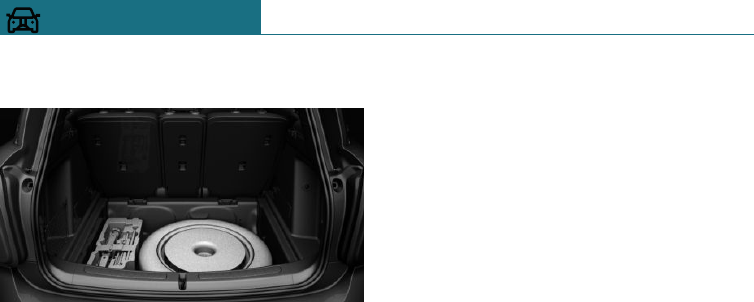
Overview
The emergency wheel and the tools for
changing wheels are located underneath the
boot floor.
Removing emergency wheel
1. Pull up and remove the boot floor.
2. Undo wing stud.
3. Remove the retaining plate or the cover.
4. Where applicable, remove the bracket
and the trailer tow hitch.
5. Remove the vehicle jack and tool holder
on the left next to the emergency wheel.
6. Push emergency wheel to left and re-
move.
Inserting the emergency wheel
1. Insert the emergency wheel on the left
and slide it to the right.
2. Where applicable, mount the bracket
and the trailer tow hitch.
3. Attach the retaining plate or the cover.
4. Screw on and tighten the wing nut.
5. Insert and secure the vehicle jack and
tool holder on the left next to the emer-
gency wheel.
6. Insert the boot floor.
Seite 292
MOBILITY Wheels and tyres
292 Online Edition for Part no. 01402988211 - II/18
Draft
from BA-76
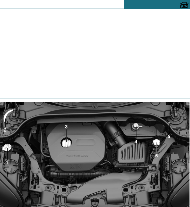
Engine compartment
Vehicle equipment
This chapter describes all standard, country-
specific and special equipment available for
the model series. Therefore equipment
which is not installed in your vehicle, for
example on account of the optional equip-
ment selected or the country specification,
may also be described here. This also ap-
plies to safety-relevant functions and sys-
tems. Comply with the relevant laws and
regulations when using the corresponding
functions and systems.
Overview
1Filler neck for washing fluid
2Vehicle identification number
3Oil filler neck
4Starting assistance, positive terminal
5Starting assistance, negative terminal
6Coolant tank
Seite 293
Engine compartment MOBILITY
293
Online Edition for Part no. 01402988211 - II/18
Draft
from BA-76
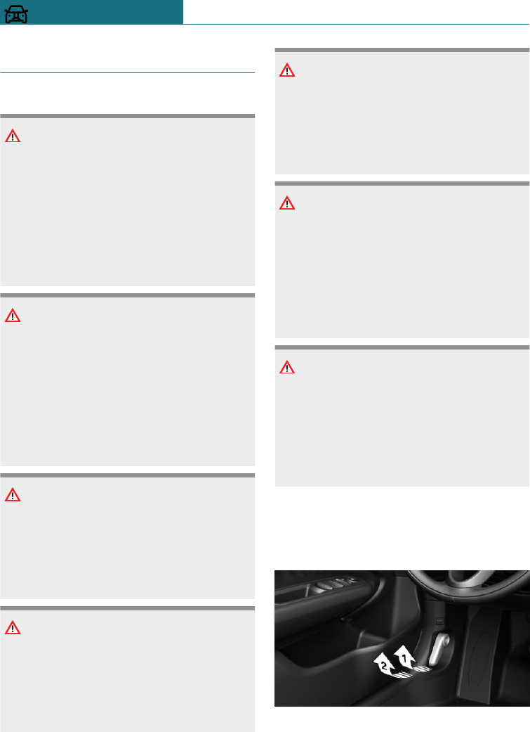
Bonnet
Safety notes
WARNING
Incorrectly performed work in the engine
compartment can damage components and
lead to a safety risk. There is a danger of
accidents or damage to property. Have
work in the engine compartment under-
taken by a Service Partner of the manufac-
turer or another qualified Service Partner
or a specialist workshop.
WARNING
The engine compartment contains moving
components. Certain components in the
engine compartment can also move when
the vehicle is switched off, for example the
radiator fan. There is a danger of injury.
Do not reach into the area of moving parts.
Keep articles of clothing and hair away
from moving parts.
WARNING
The bonnet has projecting parts on the in-
side, for example locking hooks. There is a
danger of injury. When the bonnet is open,
watch out for projecting parts and keep
these areas clear.
WARNING
If the bonnet is not correctly locked, it can
come open during the journey and impair
visibility. There is a danger of accidents.
Stop immediately and close the bonnet
correctly.
WARNING
Parts of the body can become trapped
when opening and closing the bonnet.
There is a danger of injury. When opening
and closing, make sure that the area of
movement of the bonnet is kept clear.
NOTE
When wipers are folded away from the
windscreen, they can be trapped when the
bonnet is opened. There is a danger of
damage to property. Before opening the
bonnet, make sure that the wipers with
wiper blades fitted are in contact with the
windscreen.
NOTE
When closing, the bonnet must lock into
place on both sides. Applying additional
pressure can damage the bonnet. There is
a danger of damage to property. Open the
bonnet again and close it firmly. Avoid ap-
plying additional pressure.
Open the bonnet
1. Pull the lever, arrow 1.
The bonnet is released.
2. After releasing the lever, pull the lever
again, arrow 2.
The bonnet is opened.
Seite 294
MOBILITY Engine compartment
294 Online Edition for Part no. 01402988211 - II/18
Draft
from BA-76
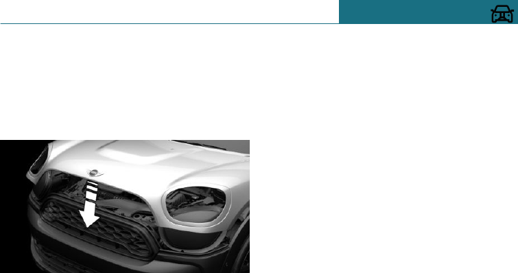
Indicator and warning lamps
If the bonnet is open, a Check Control mes-
sage is shown.
Closing the bonnet
Allow the bonnet to drop from a height of
approximately 40 cm, approximately 16 in,
arrow.
The bonnet must engage into place on both
sides.
Seite 295
Engine compartment MOBILITY
295
Online Edition for Part no. 01402988211 - II/18
Draft
from BA-76
Engine oil
Vehicle equipment
This chapter describes all standard, country-
specific and special equipment available for
the model series. Therefore equipment
which is not installed in your vehicle, for
example on account of the optional equip-
ment selected or the country specification,
may also be described here. This also ap-
plies to safety-relevant functions and sys-
tems. Comply with the relevant laws and
regulations when using the corresponding
functions and systems.
General
The engine oil consumption depends on the
driving style and operating conditions.
Therefore check the engine oil level regu-
larly each time you fill up with fuel by tak-
ing a detailed measurement.
Engine oil consumption can be increased,
for example, in the following situations:
–Dynamic driving style.
–Running in the engine.
–Engine idling.
–Use of engine oil grades categorised as
unsuitable.
Different Check Control messages are
shown, depending on the engine oil level.
Safety notes
NOTE
Too little engine oil causes engine damage.
There is a danger of damage to property.
Top up with engine oil immediately.
NOTE
Too much engine oil can damage the en-
gine or the catalytic converter. There is a
danger of damage to property. Do not top
up with too much engine oil. If there is too
much engine oil, have the engine oil level
corrected by a Service Partner of the man-
ufacturer or another qualified Service
Partner or a specialist workshop.
Electronic oil measurement
General
Electronic oil measurement has two meas-
urement principles:
–Monitoring.
–Detailed measurement.
When frequently making short trips or us-
ing a dynamic driving style, for example
taking corners at high speed, regularly per-
form a detailed measurement.
Monitoring
Principle
The engine oil level is electronically moni-
tored during the journey and can be shown
on the Control Display.
Seite 296
MOBILITY Engine oil
296 Online Edition for Part no. 01402988211 - II/18
Draft
from BA-76
If the engine oil level is outside its permis-
sible operating range, a Check Control mes-
sage is shown.
Operating requirements
A current measurement is available after
approximately 30 minutes of normal driv-
ing.
Displaying the engine oil level
Using the on-board monitor:
1. "My MINI"
2. "Vehicle status"
3. "Engine oil level"
The engine oil level is displayed.
System limits
When frequently making short trips or us-
ing a dynamic driving style, it may not be
possible to calculate a measurement. In this
case, the measurement for the last, suffi-
ciently long journey is displayed.
Detailed measurement
Principle
The engine oil level is checked when the ve-
hicle is stationary and is shown on a scale.
If the engine oil level is outside its permis-
sible operating range, a Check Control mes-
sage is shown.
General
During the measurement, the idle speed is
slightly raised.
Operating requirements
–Vehicle is standing horizontally.
–Manual gearbox: gear lever in neutral
position, clutch and accelerator pedal
not pressed.
–Steptronic transmission: selector lever
in selector lever position N or P and ac-
celerator pedal not pressed.
–Engine is running and is at operating
temperature.
Carrying out a detailed measurement
Using the on-board monitor:
1. "My MINI"
2. "Vehicle status"
3. "Engine oil level"
4. "Measure engine oil level"
5. "Start measurement"
The engine oil level is checked and shown
on a scale.
Adding engine oil
General
Do not top up engine oil unless a message is
displayed in the instrument cluster. The
top-up amount is specified in the message
on the instrument cluster.
Only replenish with suitable types of engine
oil, see page 298.
Safely park the vehicle and switch off the
ignition before replenishing the engine oil.
Ensure not to top up with too much engine
oil.
Safety notes
WARNING
Service products, for example oils, greases,
coolants and fuels, can contain substances
that are harmful to health. There is a dan-
ger of injury or even death. Comply with
the instructions on the containers. Do not
allow service products to come into con-
Seite 297
Engine oil MOBILITY
297
Online Edition for Part no. 01402988211 - II/18
Draft
from BA-76
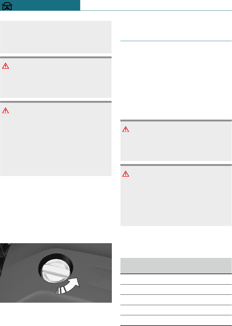
tact with clothing, skin or eyes. Do not
pour service products into other bottles.
Keep service products out of the reach of
children.
NOTE
Too little engine oil causes engine damage.
There is a danger of damage to property.
Top up with engine oil immediately.
NOTE
Too much engine oil can damage the en-
gine or the catalytic converter. There is a
danger of damage to property. Do not top
up with too much engine oil. If there is too
much engine oil, have the engine oil level
corrected by a Service Partner of the man-
ufacturer or another qualified Service
Partner or a specialist workshop.
Overview
The oil filler neck is in the engine compart-
ment, see page 293.
Adding engine oil
1. Open the bonnet, see page 294.
2. Turn the cap anticlockwise to open.
3. Add engine oil.
4. Tighten cap.
Engine oil grades for topping
up
General
The engine oil quality is decisive for the
lifetime of the engine.
Only replenish with the types of engine oil
that are listed.
Some engine oil grades are not available in
all countries.
Safety notes
NOTE
Oil additives can damage the engine.
There is a danger of damage to property.
Do not use oil additives.
NOTE
Using the wrong engine oil can result in
engine malfunctions and damage. There is
a danger of damage to property. When se-
lecting the engine oil, make sure that the
oil specification of the engine oil is cor-
rect.
Suitable engine oil grades
Replenish with engine oils with the
following oil specifications.
Petrol engine without exhaust gas parti-
cle filter
BMW Longlife-01.
BMW Longlife-01 FE.
BMW Longlife-04.
BMW Longlife-12 FE.
BMW Longlife-14 FE+.
Seite 298
MOBILITY Engine oil
298 Online Edition for Part no. 01402988211 - II/18
Draft
from BA-76
Petrol engine with exhaust gas particle
filter
BMW Longlife-04.
BMW Longlife-12 FE.
Diesel engine
BMW Longlife-04.
BMW Longlife-12 FE.
Alternative engine oil grades
If suitable engine oils are not available, up
to 1 litre, approximately 2 pints, of an en-
gine oil with the following oil specification
can be used for topping up:
Petrol engine without exhaust gas parti-
cle filter
ACEA A3/B4.
ACEA C2.
ACEA C3.
Petrol engine with exhaust gas particle
filter
ACEA C2.
ACEA C3.
Diesel engine
ACEA C2.
ACEA C3.
Viscosity classes
When selecting an engine oil, make sure
that the engine oil belongs to one of the
following viscosity classes:
Viscosity classes
SAE 0W-20.
SAE 5W-20.
SAE 0W-30.
SAE 5W-30.
SAE 0W-40.
SAE 5W-40.
Information on suitable oil specifications
and viscosities of engine oils can be ob-
tained from a Service Partner of the manu-
facturer or another qualified Service Partner
or a specialist workshop.
Oil change
NOTE
Engine oil not replaced in time can lead to
increased engine wear and thus engine
damage. There is a danger of damage to
property. Do not exceed the service date
indicated in the vehicle.
The manufacturer of the vehicle recom-
mends having the engine oil changed by a
Service Partner of the manufacturer or an-
other qualified Service Partner or a special-
ist workshop.
Seite 299
Engine oil MOBILITY
299
Online Edition for Part no. 01402988211 - II/18
Draft
from BA-76
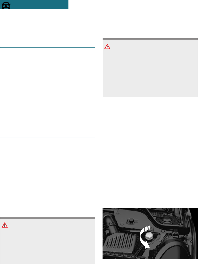
Coolant
Vehicle equipment
This chapter describes all standard, country-
specific and special equipment available for
the model series. Therefore equipment
which is not installed in your vehicle, for
example on account of the optional equip-
ment selected or the country specification,
may also be described here. This also ap-
plies to safety-relevant functions and sys-
tems. Comply with the relevant laws and
regulations when using the corresponding
functions and systems.
General
Coolant is a mixture of water and an addi-
tive.
Not all commercially available additives are
suitable for the vehicle. Information regard-
ing suitable additives is available from a
Service Partner of the manufacturer or an-
other qualified Service Partner or a special-
ist workshop.
Safety notes
WARNING
If the cooling system is opened when the
engine is hot, coolant can escape and
cause scalds. There is a danger of injury.
Only open the cooling system when the
engine has cooled down.
WARNING
Additives are harmful to health and incor-
rect additives can damage the engine.
There is a danger of injury and damage to
property. Do not allow additives to come
into contact with clothing, skin or eyes,
and do not swallow them. Only use suita-
ble additives.
Coolant level
Overview
The coolant tank is located in the engine
compartment, see page 293.
Open the bonnet, see page 294.
Checking
In the coolant tank there are yellow Min
and Max markings.
1. Allow the engine to cool down.
2. Turn cap on coolant tank slightly anti-
clockwise, then allow the pressure to es-
cape.
Seite 300
MOBILITY Coolant
300 Online Edition for Part no. 01402988211 - II/18
Draft
from BA-76
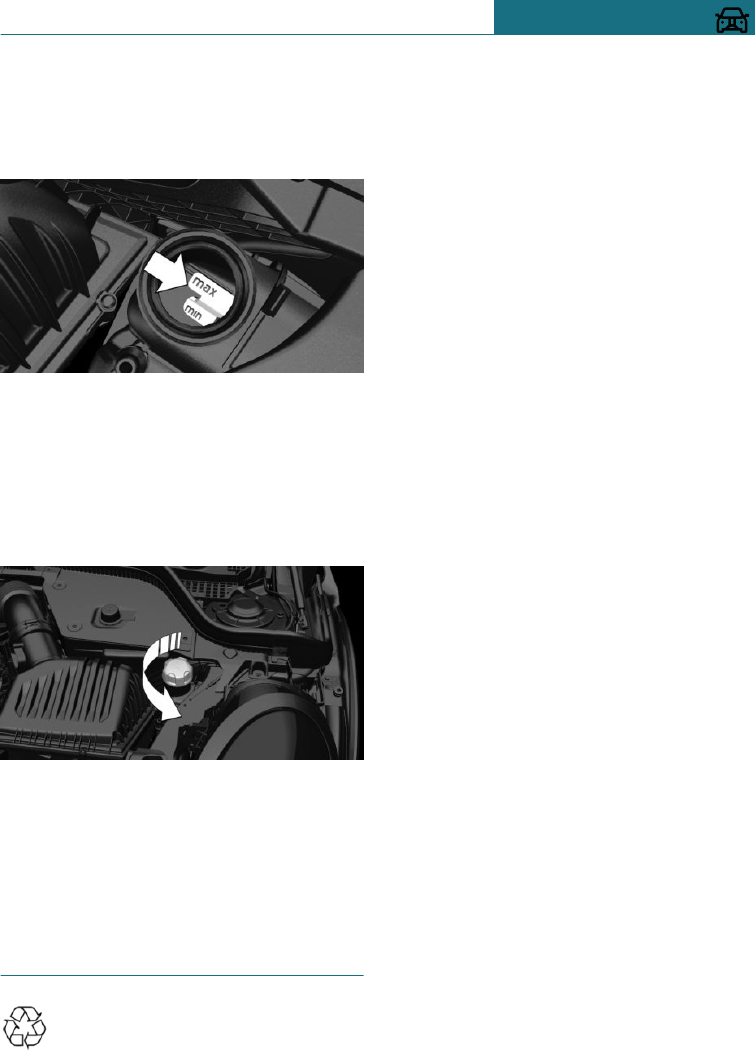
3. Open cap on coolant tank.
4. The coolant level is correct if it is be-
tween the Min. and Max. marks in the
filler neck.
Topping up
1. Allow the engine to cool down.
2. Turn the cap on the coolant tank slightly
anticlockwise until it starts to open,
then allow the pressure to escape before
opening it fully.
3. If necessary, slowly top up to the correct
level; do not overfill.
4. Tighten cap.
5. Have the cause of coolant loss rectified
as soon as possible.
Disposal
When disposing of coolant and cool-
ant additives, comply with the rele-
vant environmental protection regulations.
Seite 301
Coolant MOBILITY
301
Online Edition for Part no. 01402988211 - II/18
Draft
from BA-76

Maintenance
Vehicle equipment
This chapter describes all standard, country-
specific and special equipment available for
the model series. Therefore equipment
which is not installed in your vehicle, for
example on account of the optional equip-
ment selected or the country specification,
may also be described here. This also ap-
plies to safety-relevant functions and sys-
tems. Comply with the relevant laws and
regulations when using the corresponding
functions and systems.
MINI Maintenance System
The Maintenance System indicates what
maintenance measures are required, thus
providing support in maintaining the road
and operational safety of the vehicle.
The exact work required and the mainte-
nance intervals may vary depending on the
country specifications. Replacement work,
spare parts, operating materials and wear
materials are calculated separately. Addi-
tional information is available from a Serv-
ice Partner of the manufacturer or another
qualified Service Partner or a specialist
workshop.
Condition Based Service, CBS
Principle
Sensors and special algorithms monitor the
conditions in which the vehicle is used. CBS
uses this information to determine the
maintenance requirement.
The system thus enables the scope of the
maintenance work to be adapted to the indi-
vidual usage profile.
General
Information on service requirements, see
page 131, can be displayed on the radio.
Service data in the remote control
Information about the maintenance require-
ment is continuously stored in the remote
control. The Service Partner can read out
this data and suggest an optimised mainte-
nance scope for your vehicle.
It is important, therefore, that you hand the
service advisor the remote control that was
last used for driving the vehicle.
Periods out of use
Periods when the vehicle is out of use with
its battery disconnected are not taken into
account.
In such cases, have any time-dependent
maintenance procedures, for example for
the brake fluid and, where applicable, the
engine oil and microfilter/activated char-
coal filter, updated by a Service Partner of
the manufacturer or another qualified Serv-
ice Partner or a specialist workshop.
Service history
Maintenance and repairs
Have maintenance and repairs carried out
by a Service Partner of the manufacturer or
another qualified Service Partner or a spe-
cialist workshop.
Seite 302
MOBILITY Maintenance
302 Online Edition for Part no. 01402988211 - II/18
Draft
from BA-76
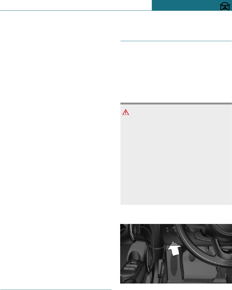
Entries
The maintenance work carried out is en-
tered in the maintenance records and the
vehicle data. As with a service booklet, the
entries provide evidence of regular mainte-
nance.
If an entry is made in the electronic service
history of the vehicle, service-relevant data
is saved both in the vehicle and on the cen-
tral IT systems of BMW AG, Munich.
The data entered in the electronic service
history can also be viewed by the new vehi-
cle owner after a change of vehicle owner. A
Service Partner of the manufacturer or an-
other qualified Service Partner or a special-
ist workshop can view the data entered in
the electronic service history.
Objection
The vehicle owner can contact a Service
Partner of the manufacturer or another
qualified Service Partner or a specialist
workshop to object to any entries being
made in the electronic service history, and
to the associated storage in the vehicle and
transfer to the vehicle manufacturer of any
data relating to his/her time as the vehicle
owner. In that case, no entry is made in the
electronic service history of the vehicle.
Displays
The maintenance visits entered can be
shown on the radio, see page 132.
For Australia/New Zealand:
maintenance
No maintenance work other than normal
maintenance is required to keep the emis-
sion levels of your vehicle within the design
limits.
Socket for on-board diagnosis,
OBD
General
Devices connected at the OBD socket trig-
ger the alarm system when the vehicle is
locked. Remove any devices connected at
the OBD socket before locking the vehicle.
Safety note
NOTE
Incorrect use of the socket for on-board di-
agnosis, OBD can result in malfunctions in
the vehicle. There is a danger of damage to
property. Only have service and mainte-
nance work involving the socket for on-
board diagnosis, OBD carried out by a
Service Partner of the manufacturer or an-
other qualified Service Partner or a spe-
cialist workshop, or other authorised per-
sons. Only connect devices that have been
tested and found to be safe for use with
the socket for on-board diagnosis, OBD.
Position
The OBD socket for checking emissions-rel-
evant components is located on the driver's
side.
Seite 303
Maintenance MOBILITY
303
Online Edition for Part no. 01402988211 - II/18
Draft
from BA-76
Emissions
–The warning lamp flashes:
There is an engine malfunction
that could damage the catalytic
converter. Have the vehicle
checked as soon as possible.
–The warning lamp is illuminated:
Deterioration of exhaust emissions.
Have the vehicle checked as soon as
possible.
Recycling
The manufacturer of the vehicle recom-
mends handing the vehicle in at a take-back
point nominated by the manufacturer at the
end of its life cycle. The regulations con-
cerning the returning of end-of-life vehicles
may vary from country to country. Addi-
tional information is available from a Serv-
ice Partner of the manufacturer or another
qualified Service Partner or a specialist
workshop.
Seite 304
MOBILITY Maintenance
304 Online Edition for Part no. 01402988211 - II/18
Draft
from BA-76
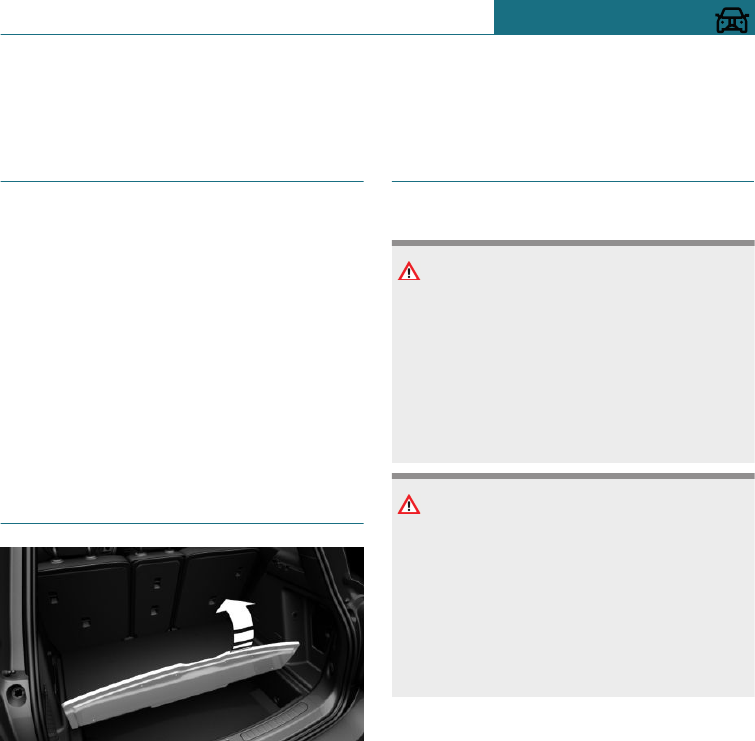
Replacing parts
Vehicle equipment
This chapter describes all standard, country-
specific and special equipment available for
the model series. Therefore equipment
which is not installed in your vehicle, for
example on account of the optional equip-
ment selected or the country specification,
may also be described here. This also ap-
plies to safety-relevant functions and sys-
tems. Comply with the relevant laws and
regulations when using the corresponding
functions and systems.
On-board tool kit
The bag containing the on-board tool kit is
located under the boot floor.
After use, secure the bag containing the on-
board tool kit to a lashing eye again.
Wiper blades
Safety notes
NOTE
The window may sustain damage if the
wiper falls onto it without the wiper blade
installed. There is a danger of damage to
property. Hold the wiper firmly when
changing the wiper blade. Do not fold in or
switch on the wiper without a wiper blade
installed.
NOTE
When wipers are folded away from the
windscreen, they can be trapped when the
bonnet is opened. There is a danger of
damage to property. Before opening the
bonnet, make sure that the wipers with
wiper blades fitted are in contact with the
windscreen.
Replacing the front wiper blades
1. To replace the wiper blades, move the
wipers in the fold-out position.
2. Fold out wiper arm and hold firm.
Seite 305
Replacing parts MOBILITY
305
Online Edition for Part no. 01402988211 - II/18
Draft
from BA-76
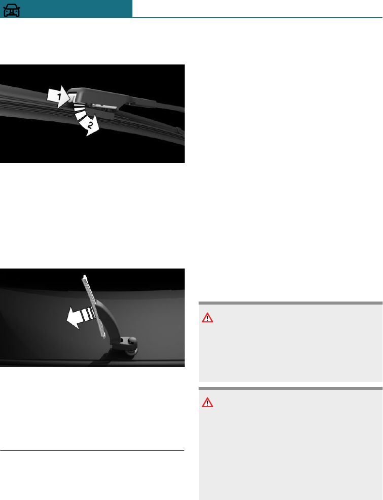
3. Press the button, arrow 1, and swing out
the wiper blade, arrow 2.
4. Insert new wiper blade. The wiper blade
must engage audibly.
5. Fold in wiper arm.
Rear wiper blade
1. Fold out wiper arm and hold firm.
2. Pull wiper blade out of the wiper arm.
3. Insert new wiper blade. The wiper blade
must engage audibly.
4. Fold in wiper arm.
Replacing lights and bulbs
General
Bulbs and lights
Lights and bulbs are an important aspect of
driving safety.
The manufacturer of the vehicle recom-
mends that you have the corresponding
work carried out by a Service Partner of the
manufacturer or another qualified Service
Partner or a specialist workshop, if you are
not familiar with it or it is not described
here.
A box of spare bulbs is available from a
Service Partner of the manufacturer or an-
other qualified Service Partner or a special-
ist workshop.
Comply with the safety notes, see page 306.
Light-emitting diodes, LEDs
Some equipment versions have light-emit-
ting diodes behind a cover as a light source.
These light-emitting diodes are similar to
conventional lasers and are classified by
legislation as Class 1 light-emitting diodes.
Comply with the safety notes, see page 306.
Safety notes
Bulbs and lights
WARNING
Bulbs can become hot during operation.
Contact with the bulbs can lead to burns.
There is a danger of injury. Only replace
bulbs when they have cooled down.
WARNING
Short circuits can occur when working on
lighting systems that are switched on.
There is a danger of injury or damage to
property. Switch the respective lights off
when working on the lighting system.
Where applicable, observe the enclosed in-
structions from the bulb manufacturer.
Seite 306
MOBILITY Replacing parts
306 Online Edition for Part no. 01402988211 - II/18
Draft
from BA-76
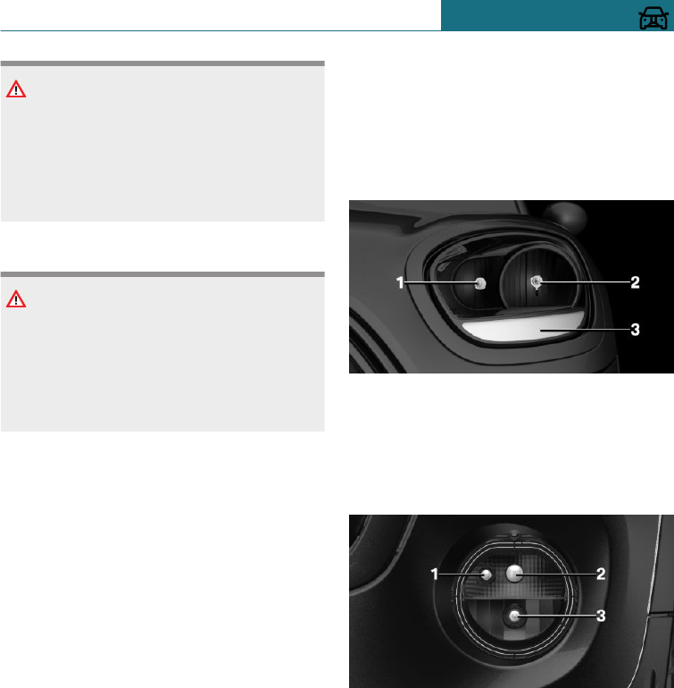
NOTE
Dirty bulbs have a reduced lifetime. There
is a danger of damage to property. Do not
touch the glass of new bulbs with your
bare hands. Use a clean tissue or similar,
or hold the bulb by its base.
Light-emitting diodes, LEDs
WARNING
Intense brightness can irritate or harm the
retina of the eye. There is a danger of in-
jury. Do not look directly into the head-
lights or other light sources. Do not re-
move covers from LEDs.
Headlight glass
During cool or humid weather, the exterior
lights can mist over on the inside. When
driving with the lights switched on, the con-
densation disappears after a short time.
There is no need to replace the headlight
glass.
If moisture increasingly forms, for example
if there are water droplets in the lamp, de-
spite the headlights being switched on,
have the headlights checked.
Headlight adjustment
Changing bulbs and lights may affect the
settings for the headlights. Have the head-
light adjustment checked and if necessary
corrected by a Service Partner of the manu-
facturer or another qualified Service Partner
or a specialist workshop.
Replacing the bulbs of halogen
front lights
Overview
Halogen headlights
1High-beam headlights
2Low-beam headlights
3Turn indicator
Bow light
1Side lights
2Daytime driving lights
3Fog lights
High-beam headlights
Follow the information regarding bulbs and
lights, see page 306.
Seite 307
Replacing parts MOBILITY
307
Online Edition for Part no. 01402988211 - II/18
Draft
from BA-76
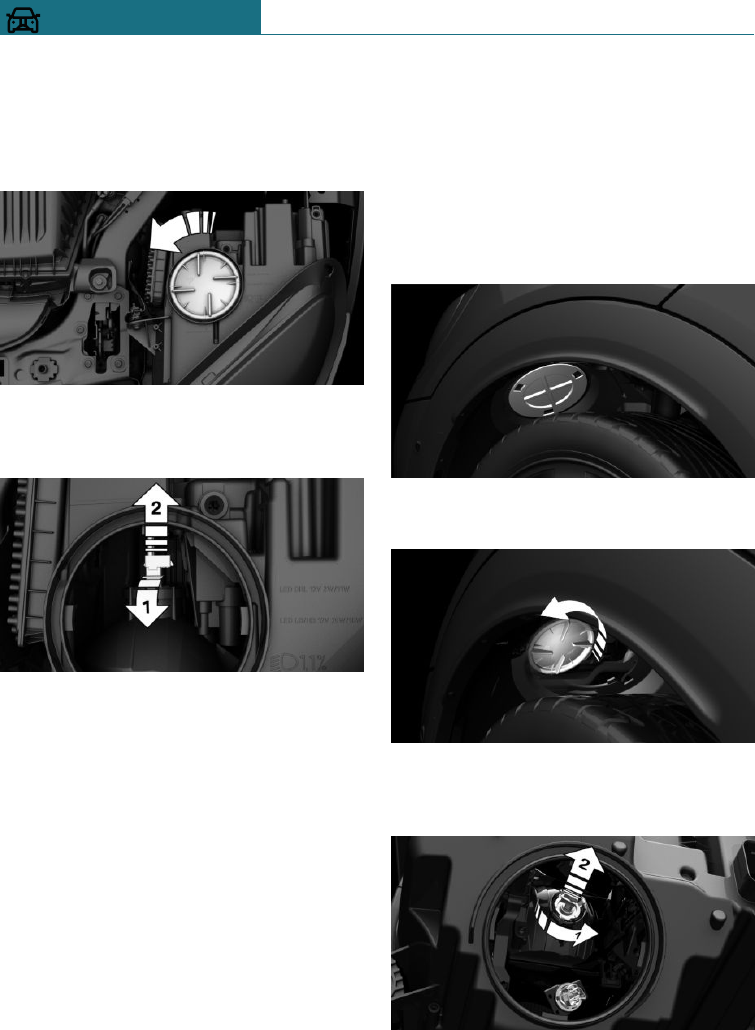
Bulbs: H7
1. Open the bonnet, see page 294.
2. Turn the cover anticlockwise and re-
move.
3. Tilt the bulb holder upwards, arrow 1,
and pull out of the headlight towards the
rear, arrow 2.
4. Pull bulb out of the bulb holder.
5. Fit the new bulb with bulb holder in re-
verse order. When doing this, position
the lug of the bulb correctly in the head-
light housing and feel the bulb holder
engage.
6. Check the position of the bulb through
the headlight glass lens.
7. Close the headlight housing with the lid.
Ensure that the lid engages.
Low-beam headlights
Follow the information regarding bulbs and
lights, see page 306.
Bulbs: H7
1. Turn the steering wheel.
2. –In the direction of travel, on the left:
turn the cover clockwise and remove
it.
–In the direction of travel, on the
right: turn the cover anticlockwise
and remove it.
3. Turn inner cover anticlockwise and re-
move.
4. Tilt the bulb holder downwards, arrow 1,
and pull out of the headlight towards the
rear, arrow 2.
5. Pull bulb out of the bulb holder.
Seite 308
MOBILITY Replacing parts
308 Online Edition for Part no. 01402988211 - II/18
Draft
from BA-76
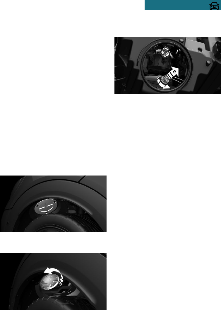
6. Fit the new bulb with bulb holder in re-
verse order. When doing this, position
the lug of the bulb correctly in the head-
light housing and feel the bulb holder
engage.
7. Check the position of the bulb through
the headlight glass lens.
8. Fit the covers. Ensure that the covers
engage.
Turn indicator
Follow the information regarding bulbs and
lights, see page 306.
Bulbs: PY21W.
1. Turn the steering wheel.
2. –In the direction of travel, on the left:
turn the cover clockwise and remove
it.
–In the direction of travel, on the
right: turn the cover anticlockwise
and remove it.
3. Turn inner cover anticlockwise and re-
move.
4. Turn bulb holder anticlockwise, arrow 1,
and remove, arrow 2.
5. Press the bulb gently into the bulb
holder, turn anticlockwise and remove.
6. To insert the new bulb and install the
covers, carry out the above steps in re-
verse order. Ensure that the covers en-
gage.
Side lights/fog lights/daytime driving
lights
Follow the information regarding bulbs and
lights, see page 306.
Bulbs:
–Side lights: W5W
–Daytime driving lights: PSX24W
–Fog lights: H8
Seite 309
Replacing parts MOBILITY
309
Online Edition for Part no. 01402988211 - II/18
Draft
from BA-76
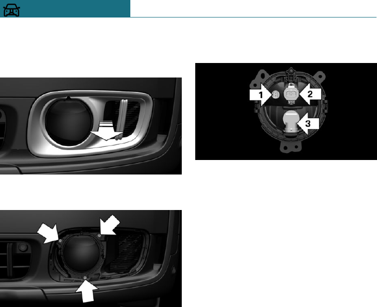
Replacing the bulbs
1. Pull the cover forwards out of the
bumper.
2. Undo the screws and remove the front
light.
3. Remove the bulb holder.
–Side lights: turn the bulb holder, ar-
row 1, anticlockwise and remove it.
–Daytime driving lights: press to-
gether the upper and lower catch of
the bulb, arrow 2, and pull out the
lamp.
To improve accessibility, remove the
bulb of the fog lights if necessary.
–Fog lights: turn the lamp, arrow 3,
anticlockwise and pull it out.
4. –Side lights: pull the lamp out of the
socket.
–Fog lights and daytime driving
lights: disconnect the lamp from the
cable.
5. To install the new bulb and install the
cover, carry out the above steps in re-
verse order.
Audibly engage the daytime driving
lights bulb holder first at the bottom,
then at the top.
LED front lights, replacing the
lamps
General
The following lights are designed in LED
technology:
–Daytime driving lights
–High-beam headlights
–Low-beam headlights
–Cornering light
–Side lights
–Fog lights
Contact a Service Partner of the manufac-
turer or another qualified Service Partner or
a specialist workshop in the case of a de-
fect.
Seite 310
MOBILITY Replacing parts
310 Online Edition for Part no. 01402988211 - II/18
Draft
from BA-76
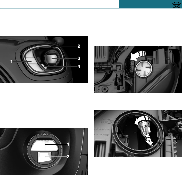
Overview
Position of the headlights
1Turn indicator
2Daytime driving lights
3Low-beam/high-beam headlights
4Cornering light
LED bow light
1Side lights
2Fog lights
Turn indicator
Follow the information regarding bulbs and
lights, see page 306.
Bulbs: PY21W.
1. Open the bonnet, see page 294.
2. Turn the cover anticlockwise and re-
move.
3. Turn bulb holder anticlockwise, arrow 1,
and remove, arrow 2.
4. Press the bulb gently into the bulb
holder, turn anticlockwise and remove.
5. To install the new bulb and install the
cover, carry out the above steps in re-
verse order.
Seite 311
Replacing parts MOBILITY
311
Online Edition for Part no. 01402988211 - II/18
Draft
from BA-76
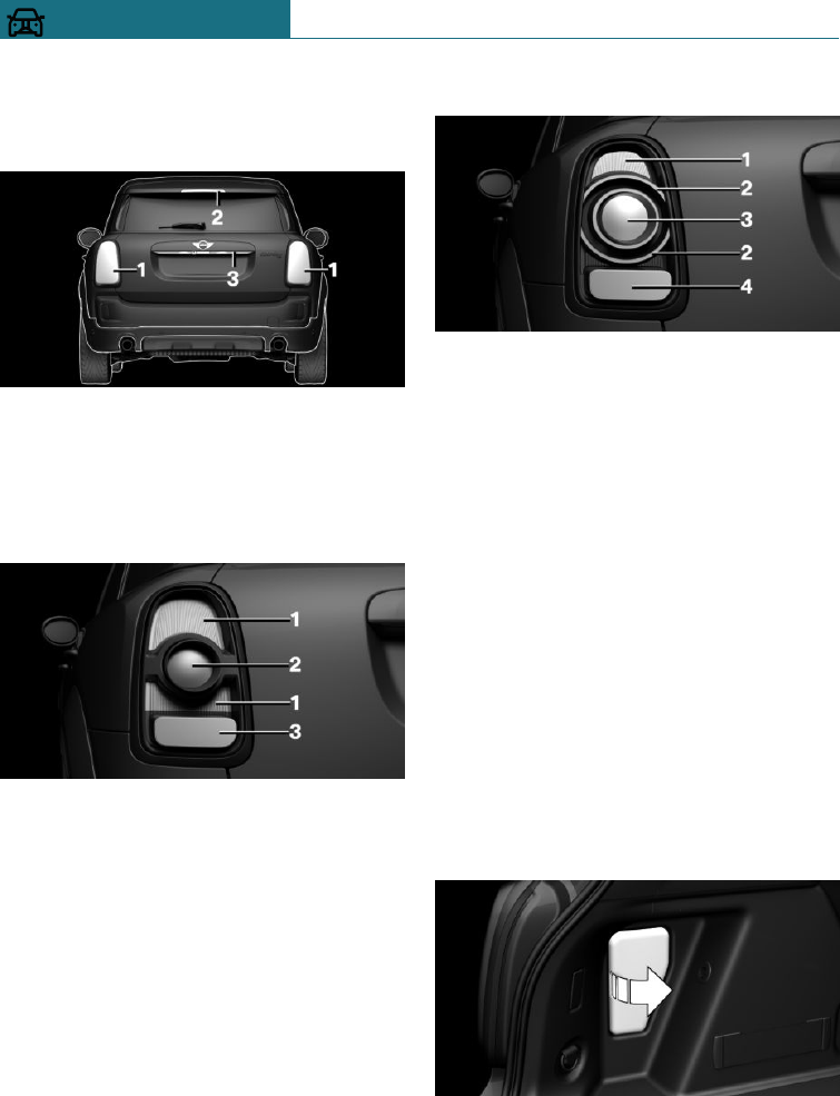
Rear lights, replacing the bulbs
Overview
1Side rear lights
2Centre brake light
3Number plate light
Side rear lights
1Brake light/tail light
2Turn indicator
3Reversing light or rear fog lamp
Side LED rear lights
1Brake light
2Tail light
3Turn indicator
4Reversing light or rear fog lamp
Side rear lights
Follow the information regarding bulbs and
lights, see page 306.
–Bulb for brake light / tail light rear light:
P21W
–Bulb for brake light / LED rear lights:
H21W
–Bulb for turn indicator: P21W
–Bulb for reversing light: P21W
–Bulb for rear fog lights: P21W
1. Open the tailgate.
2. Remove the left or right cover.
3. Undo plug connection, arrow 2, on bulb
holder through the opening.
Seite 312
MOBILITY Replacing parts
312 Online Edition for Part no. 01402988211 - II/18
Draft
from BA-76
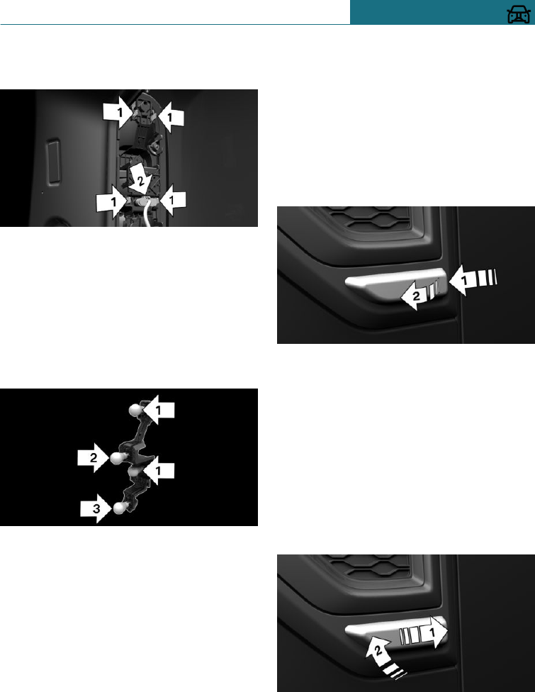
Press catches, arrow 1, together and re-
move the bulb holder.
4. Remove the bulb holder out of the open-
ing.
5. Press faulty bulb gently into the socket,
turn anticlockwise and remove.
–Arrow 1: brake light/tail light
–Arrow 2: turn indicator
–Arrow 3: reversing light or rear fog
lamp
6. To insert the new bulb and attach the
bulb holder, proceed in the opposite se-
quence. Ensure that the bulb holder en-
gages in all fastenings.
Centre brake light and number plate
lights
Follow the information regarding bulbs and
lights, see page 306.
The lights use LED technology. Contact a
Service Partner of the manufacturer or an-
other qualified Service Partner or a special-
ist workshop in the case of a defect.
Side indicator lamps, replacing the
lamps
Follow the information regarding bulbs and
lights, see page 306.
Bulb: WY5W
1. Push side turn indicator forwards in the
direction of travel, arrow 1, and swivel it
outwards, arrow 2.
2. –In the direction of travel, left: turn
the bulb holder clockwise and re-
move.
–In the direction of travel, on the
right: turn the bulb holder anticlock-
wise and remove.
3. Replace bulb.
4. Insert the bulb holder.
5. Insert the side turn indicator at the rear,
arrow 1, and swivel it in at the front, ar-
row 2.
Seite 313
Replacing parts MOBILITY
313
Online Edition for Part no. 01402988211 - II/18
Draft
from BA-76
Car battery
Maintenance
The battery is maintenance-free.
The contained quantity of acid is sufficient
for the lifetime of the battery.
More information regarding the battery can
be obtained from a Service Partner of the
manufacturer or another qualified Service
Partner or a specialist workshop.
Replacing the vehicle battery
General
The manufacturer of your vehicle recom-
mends having a Service Partner of the man-
ufacturer or another qualified Service Part-
ner or a specialist workshop register the
vehicle battery to the vehicle after the bat-
tery has been replaced. Once the battery has
been registered again, all comfort functions
will be available without restriction and any
Check Control messages relating to the
comfort functions will no longer be dis-
played.
Safety note
NOTE
Vehicle batteries that are classified as un-
suitable may damage systems or result in
functions no longer being carried out.
There is a danger of damage to property.
Only use vehicle batteries that have been
classified as suitable by the vehicle manu-
facturer.
Charging the battery
General
Ensure the charge level of the battery is
sufficient to guarantee the full life of the
battery.
The battery may need to be charged in the
following cases:
–When making frequent short journeys.
–If the vehicle is not used for periods of
longer than one month.
–Steptronic transmission: when leaving
for long periods in selector lever posi-
tion D, R or N.
Safety note
NOTE
Battery chargers for the vehicle battery
can operate with high voltages and high
currents, which can overload or damage
the 12-volt on-board network. There is a
danger of damage to property. Only con-
nect battery chargers for the vehicle bat-
tery to the jump-starting connections in
the engine compartment.
Jump-starting connections
Only charge the battery via the jump-start-
ing connections, see page 319, in the en-
gine compartment and with the engine
switched off.
Battery charger
Battery chargers developed especially for
the vehicle and suitable for the on-board
network can be obtained from a Service
Partner of the manufacturer or another
qualified Service Partner or a specialist
workshop.
Seite 314
MOBILITY Replacing parts
314 Online Edition for Part no. 01402988211 - II/18
Draft
from BA-76
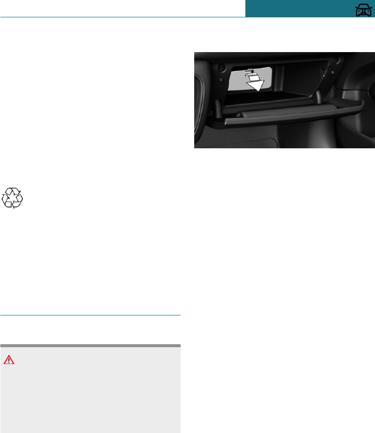
Power failure
Following an electrical power outage, some
equipment will have to be reinitialised or
individual settings will need to be updated,
for example:
–Time: update.
–Date: update.
–Seat and mirror memory: re-save posi-
tions.
–Glass Roof: initialise system.
Disposing of the old battery
Dispose of old batteries at a Service
Partner of the manufacturer or an-
other qualified Service Partner or a
specialist workshop or hand them into an
authorised collecting point.
Batteries filled with acid should be trans-
ported and stored upright. Protect batteries
against falling over when in transit.
Fuses
Safety note
WARNING
Incorrect or repaired fuses can overload
electrical cables and components. There is
a risk of fire. Do not repair blown fuses or
renew them with fuses of a different col-
our or amp rating.
Accessing the fuses
Fuses are located in glove box.
1. Open glove box.
2. Pivot the flap down, see arrow.
Fuse assignment information and details on
the positions of any other fuse boxes can be
found in a separate leaflet in the fuse box.
Replacing fuses
The manufacturer of the vehicle recom-
mends having fuses changed by a Service
Partner of the manufacturer or another
qualified Service Partner or a specialist
workshop.
Seite 315
Replacing parts MOBILITY
315
Online Edition for Part no. 01402988211 - II/18
Draft
from BA-76
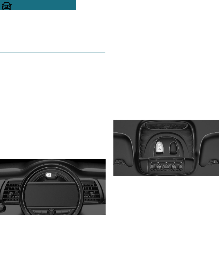
Breakdown Assist
Vehicle equipment
This chapter describes all standard, country-
specific and special equipment available for
the model series. Therefore equipment
which is not installed in your vehicle, for
example on account of the optional equip-
ment selected or the country specification,
may also be described here. This also ap-
plies to safety-relevant functions and sys-
tems. Comply with the relevant laws and
regulations when using the corresponding
functions and systems.
Hazard warning lights
The button is situated above the Control
Display.
Intelligent emergency call
Principle
The system can be used for sending an
emergency call in emergency situations.
General
Press the SOS button in an emergency only.
Even if no emergency call through MINI is
possible, in some cases an emergency call
may still be established to a public emer-
gency call number. This depends on factors
such as the specific mobile telephone net-
work and the national regulations.
For technical reasons, it might not be possi-
ble to make an emergency call in highly ad-
verse conditions.
Overview
SOS button in roof lining
Operating requirements
–The ignition is switched on.
–Emergency call system is functional.
–SIM card integrated into the vehicle is
activated.
Automatically activating
emergency calls
In certain circumstances, for example de-
ployment of the airbags, an emergency call
may be placed automatically immediately af-
ter an accident of corresponding severity.
An automatic emergency call is not influ-
enced by pressing the SOS button.
Seite 316
MOBILITY Breakdown Assist
316 Online Edition for Part no. 01402988211 - II/18
Draft
from BA-76

Triggering an emergency call
manually
1. Briefly press the cover flap to open it.
2. Press the SOS button until the LED on
the button is illuminated green.
–The LED is illuminated green when the
emergency call has been activated.
If a cancellation request is shown on the
radio display, the emergency call can be
cancelled.
If the situation permits, wait in the vehi-
cle until voice contact has been estab-
lished.
–The LED flashes green when the con-
nection to the emergency number has
been established.
When an emergency call is sent via
MINI, data is sent to the emergency call
centre in order to decide what rescue
measures are required. The data may in-
clude, for example, the current position
of the vehicle, if this can be determined.
If questions posed by the emergency call
centre remain unanswered, rescue
measures are automatically initiated.
If you can no longer hear the emergency
call centre through the loudspeakers,
the hands-free system, for example, may
be broken. However, the emergency call
centre may still be able to hear you
speak.
The emergency call centre ends the emer-
gency call.
Mobile Service
General
In many countries, the Mobile Service is
available by phone twenty-four hours a day,
seven days a week. This service can render
assistance in the event of a breakdown.
Requirements
–Active MINI Connected contract or
equipment with intelligent emergency
call.
–Mobile reception.
–Ignition or standby state is switched on.
Breakdown assistance
Principle
The Mobile Service offered by the MINI can
be contacted if you require help in the
event of a breakdown.
General
In the case of a breakdown, data on the ve-
hicle condition can be transferred to the
Mobile Service. It is possible that malfunc-
tions can be remedied directly.
Contact with the Mobile Service can also be
done with a Check Control message, see
page 125.
Starting breakdown assistance
When equipped with Teleservices, support
is provided first through the Teleservice Di-
agnosis and then by the Teleservice Assis-
tance.
Using the on-board monitor:
1. "MINI Connected"
2. "MINI Assistance"
3. "MINI Roadside Assistance"
A voice connection is established.
Teleservice Diagnosis
Teleservice Diagnosis enables the transfer
of detailed vehicle data that is necessary for
diagnosis of the vehicle via mobile teleph-
ony. This data is transferred automatically.
A voice connection to Mobile Service is es-
tablished.
Seite 317
Breakdown Assist MOBILITY
317
Online Edition for Part no. 01402988211 - II/18
Draft
from BA-76
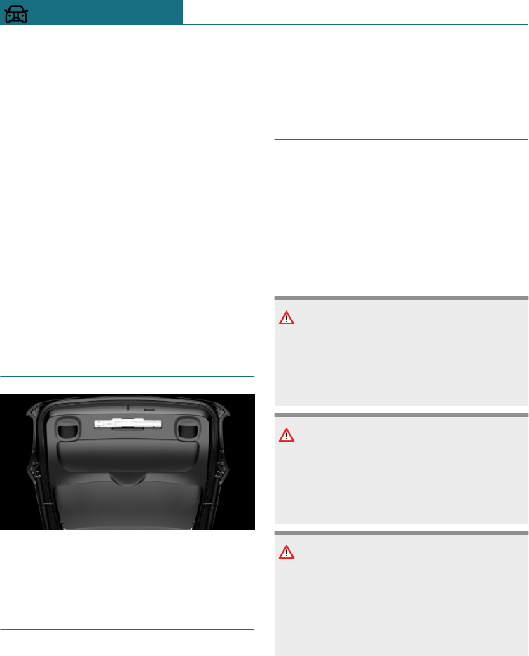
Starting Teleservice Assistance
Teleservice Assistance enables a more in-
depth diagnosis of the vehicle by Mobile
Service via mobile telephony.
You can launch Teleservice Assistance by
requesting it through Mobile Service.
1. Park the vehicle safely.
2. Apply the parking brake.
3. Control Display is switched on.
4. "Teleservice Help"
Certain vehicle functions may be restored
to a drivable condition.
If this is not possible, further measures will
be initiated, for example Mobile Service will
be informed.
Warning triangle
The warning triangle is located in the tail-
gate. To remove, release the mounts.
First-aid kit
General
Some items in the kit have a limited shelf
life.
Check the use-by dates of the contents reg-
ularly and replace any items that have ex-
pired.
Storage
The first-aid kit is in the boot.
Starting assistance
General
If the vehicle battery is discharged, the en-
gine can be started using two jump leads
from another vehicle's battery. Use only
jump leads with fully insulated terminal
clamps.
Safety notes
DANGER
Touching live components can result in an
electric shock. There is a danger of injury
or even death. Do not touch any compo-
nents that could be live.
WARNING
Connecting the jump leads in the wrong
sequence can cause sparks. There is a dan-
ger of injury. Comply with the correct se-
quence when connecting up.
NOTE
Contact between the bodies of the two ve-
hicles can result in a short circuit during
starting assistance. There is a danger of
damage to property. Make sure there is no
contact between the bodies.
Preparations
1. Check whether the battery in the other
vehicle shows 12 volts. Information
about the voltage is provided on the bat-
tery.
Seite 318
MOBILITY Breakdown Assist
318 Online Edition for Part no. 01402988211 - II/18
Draft
from BA-76
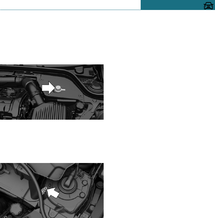
2. Switch off the engine of the donor vehi-
cle.
3. Switch off any electrical systems in both
vehicles.
Jump-starting connections
The jump-starting connection in the engine
compartment serves as the positive battery
terminal.
Open the cover of the jump-starting connec-
tion.
A special connection on the body serves as
battery negative terminal.
Connecting the cables
Do not deviate from the procedure descri-
bed below, otherwise personal injury could
result or both vehicles could be damaged.
1. Remove the cover of the jump-starting
connection.
2. Connect a terminal clamp on the posi-
tive/+ jump lead to the positive terminal
of the battery or the corresponding
jump-starting connection on the donor
vehicle.
3. Connect the other terminal clamp to the
battery's positive terminal or to the cor-
responding jump-starting connection on
the vehicle to be started.
4. Connect a terminal clamp on the nega-
tive/– jump lead to the negative termi-
nal of the battery or the corresponding
engine or body earth connection on the
donor vehicle.
5. Connect the second terminal clamp to
the negative terminal of the battery or
to a corresponding engine or body earth
connection on the vehicle to be started.
Starting the engine
Do not use the spray products sold as start-
ing aids.
1. Start the engine of the donor vehicle and
allow it to run for a few minutes at a
slightly increased idle speed.
If starting a diesel vehicle: allow the en-
gine of the donor vehicle to run for ap-
proximately 10 minutes.
2. Start the engine of the vehicle to be
started as normal.
If an initial attempt to start the engine
fails, wait several minutes until the dis-
charged battery has been recharged to a
slightly greater degree.
3. Allow both engines to run for a few mi-
nutes.
4. Disconnect the jump leads in the oppo-
site order from that in which they were
originally attached.
Check the battery if necessary and have it
recharged.
Seite 319
Breakdown Assist MOBILITY
319
Online Edition for Part no. 01402988211 - II/18
Draft
from BA-76
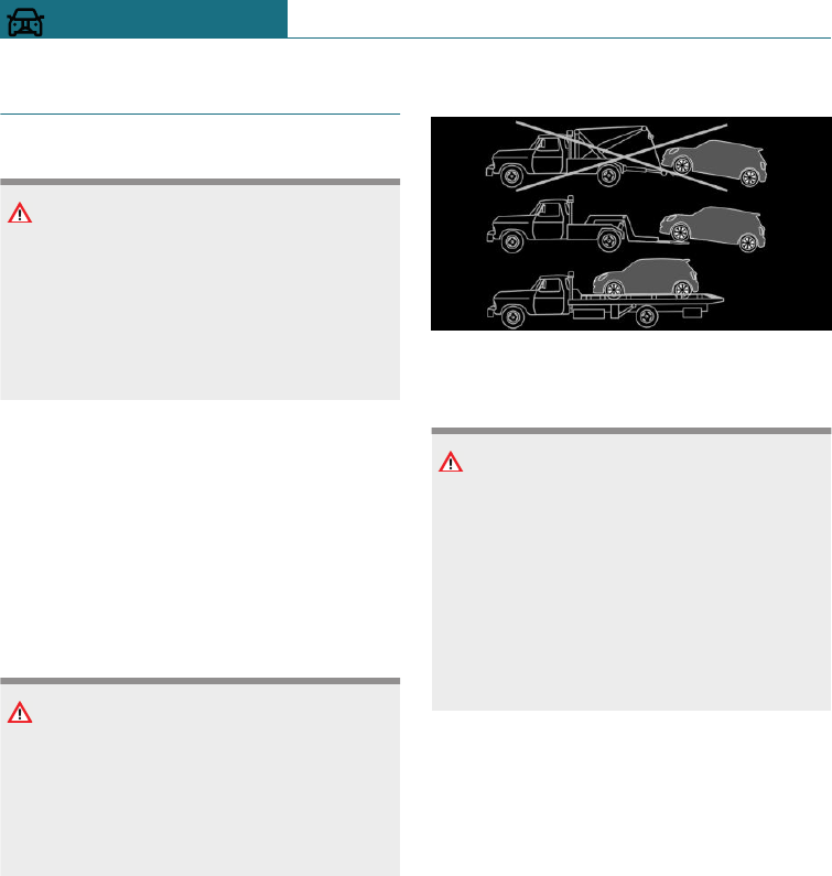
Tow-starting and towing
Safety note
WARNING
Due to system limitations, individual func-
tions may not work properly when tow
starting/towing with activated Intelligent
Safety Systems. There is a danger of acci-
dents. Switch off all Intelligent Safety Sys-
tems before tow-starting/towing.
Steptronic transmission with
driven front axle: transporting the
vehicle
General
The vehicle must not be towed if the front
wheels are in contact with the ground.
Safety note
NOTE
If the vehicle is towed with a lifted rear
axle, the vehicle can be damaged. There is
a danger of damage to property. Only have
the vehicle towed with a lifted front axle
or transported on a load platform.
Pushing the vehicle
To remove a broken-down vehicle from a
dangerous area, it can be pushed for a short
distance.
Roll or push, see page 119, the vehicle.
Towing truck
Have the vehicle transported by a towing
truck with a hoisting frame, or hoisted onto
a loading platform.
NOTE
The vehicle can become damaged when
raising and securing it.
There is a danger of damage to property.
–Raise the vehicle with suitable equip-
ment.
–Do not raise or secure the vehicle by
its towing eye, body parts or suspen-
sion parts.
Steptronic transmission with ALL4:
transporting the vehicle
General
Do not attempt to have the vehicle towed.
Pushing the vehicle
To remove a broken-down vehicle from a
dangerous area, it can be pushed for a short
distance.
Roll or push, see page 119, the vehicle.
Seite 320
MOBILITY Breakdown Assist
320 Online Edition for Part no. 01402988211 - II/18
Draft
from BA-76
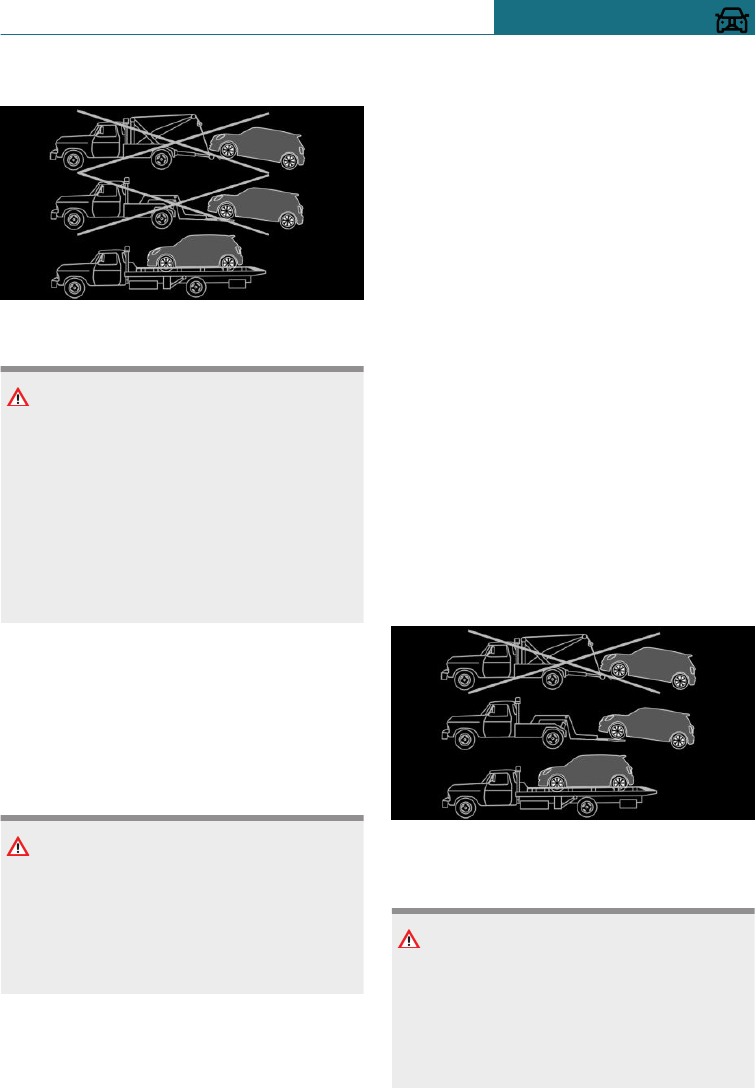
Towing truck
Only have the vehicle transported on a
truck bed.
NOTE
The vehicle can become damaged when
raising and securing it.
There is a danger of damage to property.
–Raise the vehicle with suitable equip-
ment.
–Do not raise or secure the vehicle by
its towing eye, body parts or suspen-
sion parts.
Manual gearbox
Towing or pushing the vehicle
A broken-down vehicle can be towed or
pushed.
Roll or push, see page 115, the vehicle.
NOTE
If a parking brake cannot be manually un-
locked, the vehicle cannot be moved or
towed. There is a danger of damage to
property. Only have the vehicle transpor-
ted on a truck bed.
Observe the following notes:
–Make sure that the ignition is switched
on, otherwise low-beam headlights, rear
lights, turn indicators and wipers will
not be available.
–Do not tow the vehicle with the rear
axle raised, otherwise the steering can
turn.
–When the engine is not running, there
is no power assistance. The steering and
brakes will require extra effort to oper-
ate.
–Greater steering wheel movements are
necessary.
–The towing vehicle must not be lighter
than the towed vehicle, otherwise it may
be unable to keep the towed vehicle reli-
ably under control.
–Do not exceed a towing speed of
50 km/h, 30 mph.
–Do not exceed a towing distance of
50 km, 30 miles.
Towing truck
With driven front axle
Have your vehicle transported by a towing
truck with a hoisting frame, or hoisted onto
a loading platform.
NOTE
The vehicle can become damaged when
raising and securing it.
There is a danger of damage to property.
–Raise the vehicle with suitable equip-
ment.
Seite 321
Breakdown Assist MOBILITY
321
Online Edition for Part no. 01402988211 - II/18
Draft
from BA-76
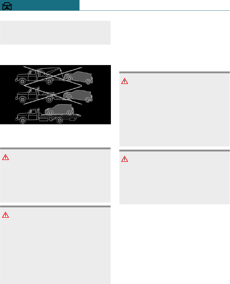
–Do not raise or secure the vehicle by
its towing eye, body parts or suspen-
sion parts.
With ALL4
Your vehicle should only be transported on
a loading platform.
NOTE
If the vehicle is towed with one axle
raised, the vehicle can be damaged. There
is a danger of damage to property. Only
have the vehicle transported on a truck
bed.
NOTE
The vehicle can become damaged when
raising and securing it.
There is a danger of damage to property.
–Raise the vehicle with suitable equip-
ment.
–Do not raise or secure the vehicle by
its towing eye, body parts or suspen-
sion parts.
Towing other vehicles
General
Switch on the hazard warning lights, de-
pending on local regulations.
If the vehicle's electrical system has failed,
the vehicle being towed must be made iden-
tifiable to following vehicles, for instance
by placing an indicating label or the warn-
ing triangle in the rear window.
Safety notes
WARNING
If the gross vehicle weight of the towing
vehicle is less than that of the vehicle to
be towed, the towing eye can be pulled off,
or the vehicle may no longer be controlla-
ble. There is a danger of accidents. Make
sure that the gross vehicle weight of the
towing vehicle is more than the weight of
the vehicle to be towed.
NOTE
If the tow bar or the towing rope is not at-
tached correctly, other vehicle parts can
be damaged. There is a danger of damage
to property. Attach the tow bar or towing
rope to the towing eye correctly.
Tow bar
The towing eyes of both vehicles should be
on the same side.
If it is impossible to avoid attaching the tow
bar at an angle, note the following:
–Tow bar clearance may be limited when
cornering.
–The tow bar will generate lateral forces
if it is attached offset.
Towing rope
Ensure that the towing rope is taut when
the towing vehicle drives off.
Use nylon ropes or straps, which will enable
the vehicle to be towed without jerking.
Seite 322
MOBILITY Breakdown Assist
322 Online Edition for Part no. 01402988211 - II/18
Draft
from BA-76
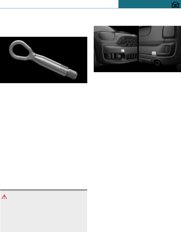
Towing eye
General
Always have the screw-on towing eye on
board the vehicle.
The towing eye can be screwed into the
front or rear end of the vehicle.
The towing eye together with the on-board
tool kit, see page 305, is located in the boot.
Using the towing eye:
–Use only the towing eye supplied with
the vehicle, and make sure that it is
screwed in fully and is tight.
–Only use the towing eye for towing on
paved roads.
–Avoid lateral loads on the towing eye,
for example do not raise the vehicle at
the towing eye.
Safety note
NOTE
If the towing eye is not used as intended,
the vehicle or towing eye may be dam-
aged. There is a danger of damage to prop-
erty. Observe the notes on using the tow-
ing eye.
Thread for towing eye
The thread for the towing eye is situated at
the front and back of the vehicle, in each
case on the right-hand side in direction of
travel.
Press the marking on the edge of the cover
to press it out.
Tow-starting
Steptronic transmission
Do not attempt to tow-start or push-start
the vehicle.
Due to the Steptronic transmission, it is not
possible to start the engine by towing.
Have the cause of the starting difficulties
rectified by a Service Partner of the manu-
facturer or another qualified Service Partner
or a specialist workshop.
Manual gearbox
If possible, do not tow-start the vehicle but
start the engine using starting assistance,
see page 318. Only tow-start when the en-
gine is cold if your vehicle has a catalytic
converter.
1. Switching on the hazard warning lights,
please observe country-specific regula-
tions.
2. Switch on the ignition, see page 102.
3. Engage 3rd gear.
4. Tow-start with the clutch pressed and
release the clutch slowly. Press the
Seite 323
Breakdown Assist MOBILITY
323
Online Edition for Part no. 01402988211 - II/18
Draft
from BA-76

clutch again immediately after the en-
gine starts.
5. Stop in a suitable location, remove the
tow bar or towing rope and switch off
the hazard warning lights.
6. Have the vehicle checked by a Service
Partner of the manufacturer or another
qualified Service Partner or a specialist
workshop.
Seite 324
MOBILITY Breakdown Assist
324 Online Edition for Part no. 01402988211 - II/18
Draft
from BA-76
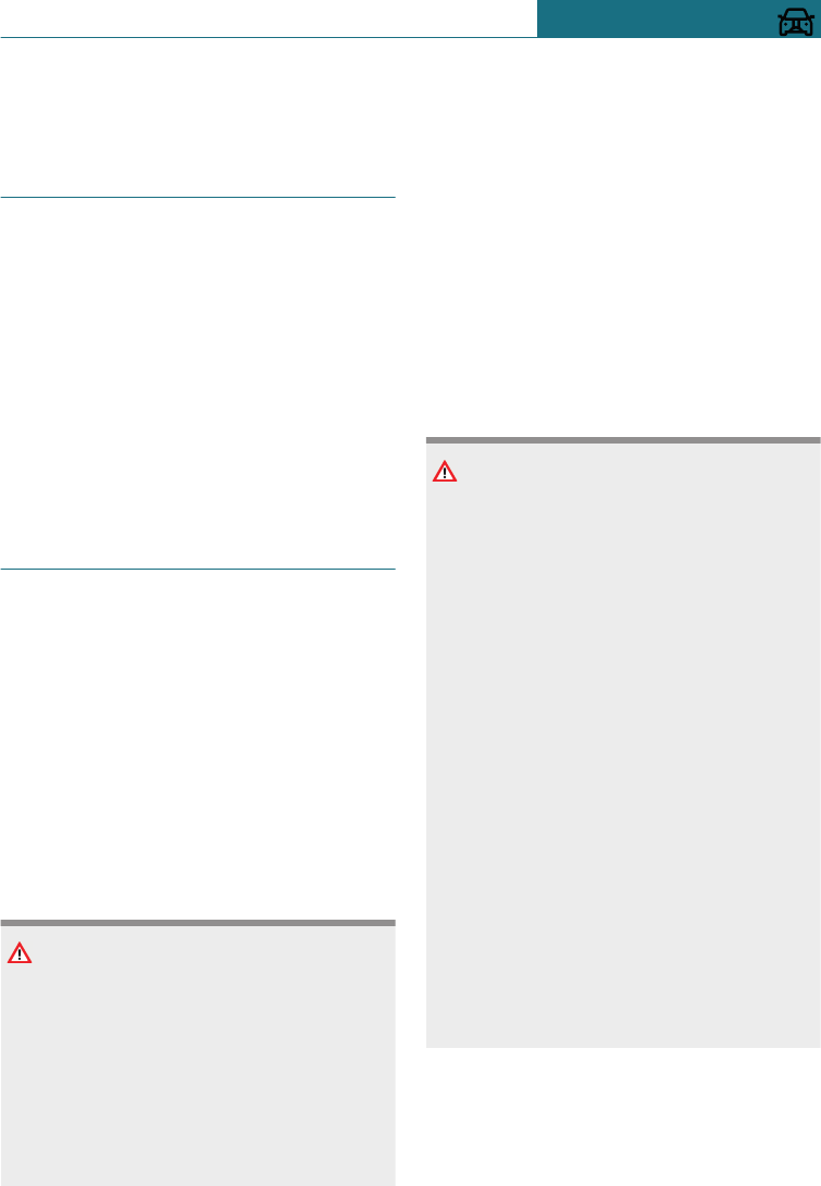
General care
Vehicle equipment
This chapter describes all standard, country-
specific and special equipment available for
the model series. Therefore equipment
which is not installed in your vehicle, for
example on account of the optional equip-
ment selected or the country specification,
may also be described here. This also ap-
plies to safety-relevant functions and sys-
tems. Comply with the relevant laws and
regulations when using the corresponding
functions and systems.
Washing the vehicle
General
Regularly remove foreign bodies, for exam-
ple, leaves, from the area below the wind-
screen with the bonnet raised.
Wash the vehicle frequently especially in
winter. Very high levels of dirt and road salt
can cause damage to the vehicle.
Steam-jet cleaners or high-pressure
cleaners
Safety note
NOTE
When cleaning with high-pressure clean-
ers, excessive pressure or excessive tem-
peratures can damage various compo-
nents. There is a danger of damage to
property. Ensure a sufficient distance and
do not spray for an extended period of
time. Comply with the instructions for the
high-pressure cleaner.
Distances and temperature
–Maximum temperature: 60 ℃/140 ℉.
–Minimum distance to sensors, cameras,
seals: 30 cm, approximately 12 in.
–Minimum distance to the Glass Roof:
80 cm, approximately 31.5 in.
Automatic car washes
Safety notes
NOTE
The vehicle can be damaged if automatic
washing bays or car washes are used in-
correctly. There is a danger of damage to
property. Observe the following notes:
–Textile car washes or systems using
soft brushes are preferable, to avoid
damage to the paintwork.
–Avoid washing bays or car washes
with guide rails higher than 10 cm,
approx. 4 in, to avoid damage to the
body.
–Note the maximum tyre width of the
guide rail so as to avoid damage to
tyres and rims.
–Fold in the exterior mirrors to avoid
damaging them.
–With rod aerial: unscrew rod aerial so
as to avoid the rod aerial breaking off.
–Deactivate the wipers and the rain
sensor (if fitted) to avoid damage to
the wiper system.
Entering a car wash with a manual
transmission
In car washes, the vehicle must be able to
roll freely.
Seite 325
General care MOBILITY
325
Online Edition for Part no. 01402988211 - II/18
Draft
from BA-76
Rolling or pushing the vehicle, see
page 115.
Entering a car wash with a Steptronic
transmission
In car washes, the vehicle must be able to
roll freely.
Rolling or pushing the vehicle, see
page 119.
Some car washes require you to get out of
the vehicle. It is not possible to lock the ve-
hicle from the outside in selector lever posi-
tion N. If an attempt is made to lock the ve-
hicle, a signal sounds.
Exiting from a car wash
Make sure that the vehicle key is in the ve-
hicle.
Start the engine, see page 103.
Headlights
Do not rub wet headlights dry and do not
use abrasive or corrosive cleaning agents.
Soak impurities such as insect residues
with shampoo and wash off with water.
Remove ice with a de-icer spray; do not use
an ice scraper.
After washing the vehicle
After the vehicle has been washed, briefly
apply the brakes to dry them otherwise the
braking effectiveness may be temporarily
reduced. The heat generated by braking
dries the brake discs and brake pads, and
protects them against corrosion.
Completely remove residues on the wind-
screens to avoid affecting visibility due to
smearing, and to reduce wiping noise and
wiper blade wear.
Vehicle care
Care products
General
MINI recommends using care and cleaning
products from MINI. Suitable care products
are available from a Service Partner of the
manufacturer or another qualified Service
Partner or a specialist workshop.
Safety note
WARNING
Cleaning agents can contain hazardous
substances or constitute a health risk.
There is a danger of injury. When cleaning
the interior, open the doors or windows.
Use only products that are intended for
cleaning the vehicle's interior. Observe the
notes on the pack.
Vehicle paintwork
General
Regular care promotes driving safety and
preserves your vehicle's value. Environmen-
tal effects in areas with higher air pollution
or natural contaminants, for example tree
resin or leaf dust, may have an effect on the
vehicle paintwork. Base the frequency and
extent of vehicle care on such factors.
Immediately remove aggressive substances,
for example spilled fuel, oil, grease or bird
droppings so as to prevent alterations and
discolourations of the paintwork.
Matt paintwork
Only use cleaning and care products that
are suitable for vehicles with matt paint-
work.
Seite 326
MOBILITY General care
326 Online Edition for Part no. 01402988211 - II/18
Draft
from BA-76
Leather care
Remove dust from the leather at regular in-
tervals with a cloth or vacuum cleaner.
Dust and road dirt will otherwise become
worked into pores and folds, causing con-
siderable abrasion and causing the leather
surface to become prematurely brittle.
In order to protect against discolouration,
for example from clothing, clean and care
for the leather approximately every two
months.
Clean light-coloured leather more frequently
as it has the tendency to soil faster.
Use leather cleaner, otherwise dirt and
grease will attack the protective coating of
the leather.
Care of upholstery fabrics
General
Regularly clean the upholstery with a vac-
uum cleaner.
In the event of heavy soiling, for example
stains caused by drinks, use a soft sponge
or a lint-free microfibre cloth with suitable
interior cleaning agents.
Clean the upholstery down to the seams us-
ing wide wiping actions. Avoid rubbing vig-
orously.
Safety note
NOTE
Open Velcro fasteners on articles of cloth-
ing can damage the seat covers. There is a
danger of damage to property. Make sure
that any Velcro fasteners on your clothing
are closed.
Care of special parts
Light alloy wheels
When cleaning the wheels while they are
installed on the vehicle, only use neutral
rim cleaner with a pH value of between 5
and 9. Do not use any abrasive cleaners or
steam cleaners above 60 ℃/140 ℉. Observe
the manufacturer's instructions.
Corrosive, acidic or alkaline cleaners may
destroy the protective layer of neighbouring
parts, such as brake discs, for example.
After cleaning, briefly apply the brakes to
dry them. The heat generated by braking
dries the brake discs and brake pads, and
protects them against corrosion.
Chrome surfaces
Carefully clean parts such as the radiator
grille and door handles with plenty of water
to which a shampoo may be added, particu-
larly if exposed to road salt.
Rubber parts
The surfaces of rubber parts can be conta-
minated or lose their shine due to environ-
mental influences. Only use water and suita-
ble care products for cleaning.
Rubber parts subjected to high wear and
tear should be treated regularly with rubber
care products. Do not use any silicone-
based care products for treating rubber
seals, otherwise these could be damaged
and become a source of noise.
Fine wood parts
Clean fine wood trims and fine wood parts
with a damp cloth only. Then dry them with
a soft cloth.
Seite 327
General care MOBILITY
327
Online Edition for Part no. 01402988211 - II/18
Draft
from BA-76
Plastic parts
NOTE
Cleaning agents containing alcohol or sol-
vents, such as nitro thinners, cold cleans-
ers, fuel or similar can damage plastic
parts. There is a danger of damage to prop-
erty. Clean with a microfibre cloth. Lightly
moisten the cloth with water.
Plastic parts include, for example:
–Imitation leather surfaces.
–Roof lining.
–Lamp lenses.
–Glass cover of instrument cluster.
–Parts sprayed matt black.
–Painted parts in the interior.
Clean with a microfibre cloth.
Lightly moisten the cloth with water.
Do not soak the roof lining.
Seat belts
WARNING
Chemical cleaners can cause irreparable
damage to the fabric of the seat belts. The
protective function of the seat belts will
be lost. There is a danger of injury or even
death. Only use a mild soap and water sol-
ution for cleaning the seat belts.
Dirt on the seat belt straps can interfere
with the action of the reel and represents a
safety hazard.
Clean only with a mild soap solution while
still fitted to the vehicle.
Never allow seat belts to retract unless they
are dry.
Carpets and foot mats
WARNING
Objects in the driver's footwell can restrict
the pedal travel, or block a pedal that has
been pressed. There is a danger of acci-
dents. Stow items in the vehicle so that
they are secure and cannot get into the
driver's footwell. Only use floor mats that
are appropriate for the vehicle and can be
securely fastened to the floor. Do not use
any loose floor mats, and do not place sev-
eral floor mats on top of one another. Make
sure that there is sufficient space for the
pedals. Ensure that the floor mats are se-
curely reattached after having been re-
moved, for example for cleaning.
Floor mats can be removed from the vehicle
to enable the interior to be cleaned more
thoroughly.
In the event of heavy soiling, clean floor
carpets using a microfibre cloth and water
or textile cleaner. Rub back and forth in the
direction of travel to prevent matting.
Trailer tow hitch with removable ball
linkage/mount for rear luggage rack
Keep ball linkage and bracket clean.
Grease or oil bearing locations, sliding sur-
faces and the small balls on the bracket pin
regularly with resin-free grease or oil.
Before using a steam cleaner or high-pres-
sure cleaner on the vehicle, remove the ball
linkage and insert the cover into the
bracket.
Do not clean ball linkage with a steam
cleaner or high pressure cleaner.
Sensors/camera lenses
Clean sensors or camera lenses using a
cloth moistened with a small amount of a
glass cleaner.
Seite 328
MOBILITY General care
328 Online Edition for Part no. 01402988211 - II/18
Draft
from BA-76
Displays/screens
NOTE
Chemical cleaners, moisture or fluids of all
kinds can damage the surface of displays
and screens. There is a danger of damage
to property. Clean with a clean, anti-static
microfibre cloth.
NOTE
The surfaces of displays can be damaged
due to improper cleaning. There is a dan-
ger of damage to property. Avoid applying
excessive pressure and do not use abra-
sive materials.
Clean with a clean, anti-static microfibre
cloth.
Laying up the vehicle
Special measures need to be taken if putting
the vehicle out of use for longer than three
months. Additional information is available
from a Service Partner of the manufacturer
or another qualified Service Partner or a
specialist workshop.
Seite 329
General care MOBILITY
329
Online Edition for Part no. 01402988211 - II/18
Draft
from BA-76

330
Online Edition for Part no. 01402988211 - II/18
Draft
from BA-76

REFERENCE
Technical data ......................................................................................... 332
Appendix .................................................................................................. 344
License Texts and Certifications ...................................................... 345
Everything from A to Z ........................................................................ 384
331
Online Edition for Part no. 01402988211 - II/18
Draft
from BA-76
Technical data
Vehicle equipment
This chapter describes all standard, country-
specific and special equipment available for
the model series. Therefore equipment
which is not installed in your vehicle, for
example on account of the optional equip-
ment selected or the country specification,
may also be described here. This also ap-
plies to safety-relevant functions and sys-
tems. Comply with the relevant laws and
regulations when using the corresponding
functions and systems.
General
The technical data and specifications in the
Owner's Handbook are reference figures.
The vehicle-specific data can deviate from
this, for example, due to selected special
equipment, country variant or country-spe-
cific measurement method. Detailed values
can be found in the permit documents, on
information plates on the vehicle or can be
requested from a Service Partner of the
manufacturer or another qualified Service
Partner or a specialist workshop.
The information in the vehicle papers al-
ways takes precedence over the information
in this Owner's Handbook.
Dimensions
The dimensions can vary depending on the
model version, equipment or country-spe-
cific measurement method.
The heights specified do not take into ac-
count add-on parts such as a roof aerial, roof
railing or spoiler. The heights can deviate,
for example, due to selected special equip-
ment, tyres, loads and suspension design.
MINI Countryman
Width with mirrors mm 2005
Width without mirrors mm 1822
Height mm 1557
Length mm 4299
Wheelbase mm 2670
Smallest turning circle dia. m (ft) 11.4 (37.5)
Seite 332
REFERENCE Technical data
332 Online Edition for Part no. 01402988211 - II/18
Draft
from BA-76
Weights
MINI One Countryman
Kerb weight, ready for road, with 75 kg, 165 lb,
load, tank 90 % full, no optional extras
Manual gearbox kg (lb) 1440 (3175)
Steptronic transmission kg (lb) 1460 (3219)
Permitted gross weight
Manual gearbox kg (lb) 1945 (4288)
Steptronic transmission kg (lb) 1975 (4354)
Load
Manual gearbox kg (lb) 580 (1279)
Steptronic transmission kg (lb) 590 (1301)
Front axle load limit
Manual gearbox kg (lb) 1010 (2227)
Steptronic transmission kg (lb) 1040 (2293)
Rear axle load limit kg (lb) 980 (2161)
MINI Cooper Countryman
Kerb weight, ready for road, with 75 kg, 165 lb,
load, tank 90 % full, no optional extras
Manual gearbox kg (lb) 1440 (3175)
Steptronic transmission kg (lb) 1465 (3230)
Permitted gross weight
Manual gearbox kg (lb) 1950 (4299)
Steptronic transmission kg (lb) 1975 (4354)
Load kg (lb) 585 (1290)
Front axle load limit
Manual gearbox kg (lb) 1015 (2238)
Steptronic transmission kg (lb) 1045 (2304)
Rear axle load limit kg (lb) 980 (2161)
Seite 333
Technical data REFERENCE
333
Online Edition for Part no. 01402988211 - II/18
Draft
from BA-76
MINI Cooper S Countryman
Kerb weight, ready for road, with 75 kg, 165 lb,
load, tank 90 % full, no optional extras
Manual gearbox kg (lb) 1505 (3318)
Steptronic transmission kg (lb) 1535 (3384)
Permitted gross weight
Manual gearbox kg (lb) 2020 (4453)
Steptronic transmission kg (lb) 2050 (4519)
Load kg (lb) 590 (1301)
Front axle load limit
Manual gearbox kg (lb) 1060 (2337)
Steptronic transmission kg (lb) 1090 (2403)
Rear axle load limit kg (lb) 1000 (2205)
MINI John Cooper Works Countryman ALL4
Kerb weight, ready for road, with 75 kg, 165 lb,
load, tank 90 % full, no optional extras
Manual gearbox kg (lb) 1615 (3560)
Steptronic transmission kg (lb) 1630 (3594)
Permitted gross weight
Manual gearbox kg (lb) 2130 (4696)
Steptronic transmission kg (lb) 2150 (4740)
Load
Manual gearbox kg (lb) 590 (1301)
Steptronic transmission kg (lb) 595 (1312)
Front axle load limit
Manual gearbox kg (lb) 1115 (2458)
Steptronic transmission kg (lb) 1130 (2491)
Rear axle load limit kg (lb) 1060 (2337)
Seite 334
REFERENCE Technical data
334 Online Edition for Part no. 01402988211 - II/18
Draft
from BA-76

MINI Cooper Countryman ALL4
Kerb weight, ready for road, with 75 kg, 165 lb,
load, tank 90 % full, no optional extras
Manual gearbox kg (lb) 1530 (3373)
Steptronic transmission kg (lb) 1545 (3406)
Permitted gross weight
Manual gearbox kg (lb) 2045 (4508)
Steptronic transmission kg (lb) 2060 (4542)
Load kg (lb) 590 (1301)
Front axle load limit
Manual gearbox kg (lb) 1070 (2359)
Steptronic transmission kg (lb) 1090 (2403)
Rear axle load limit kg (lb) 1030 (2271)
MINI Cooper S Countryman ALL4
Kerb weight, ready for road, with 75 kg, 165 lb,
load, tank 90 % full, no optional extras
Manual gearbox kg (lb) 1585 (3494)
Steptronic transmission kg (lb) 1605 (3538)
Permitted gross weight
Manual gearbox kg (lb) 2110 (4652)
Steptronic transmission kg (lb) 2120 (4674)
Load
Manual gearbox kg (lb) 600 (1323)
Steptronic transmission kg (lb) 590 (1301)
Front axle load limit
Manual gearbox kg (lb) 1100 (2425)
Steptronic transmission kg (lb) 1120 (2469)
Rear axle load limit kg (lb) 1050 (2315)
Seite 335
Technical data REFERENCE
335
Online Edition for Part no. 01402988211 - II/18
Draft
from BA-76
MINI One D Countryman
Kerb weight, ready for road, with 75 kg, 165 lb,
load, tank 90 % full, no optional extras
Manual gearbox kg (lb) 1 (2)
Steptronic transmission kg (lb) 1 (2)
Permitted gross weight
Manual gearbox kg (lb) 1 (2)
Steptronic transmission kg (lb) 1 (2)
Load
Manual gearbox kg (lb) 1 (2)
Steptronic transmission kg (lb) 1 (2)
Front axle load limit
Manual gearbox kg (lb) 1 (2)
Steptronic transmission kg (lb) 1 (2)
Rear axle load limit kg (lb) 1 (2)
MINI Cooper D Countryman
Kerb weight, ready for road, with 75 kg, 165 lb,
load, tank 90 % full, no optional extras
Manual gearbox kg (lb) 1 (2)
Steptronic transmission kg (lb) 1 (2)
Permitted gross weight
Manual gearbox kg (lb) 1 (2)
Steptronic transmission kg (lb) 1 (2)
Load
Manual gearbox kg (lb) 1 (2)
Steptronic transmission kg (lb) 1 (2)
Front axle load limit
Manual gearbox kg (lb) 1 (2)
Seite 336
REFERENCE Technical data
336 Online Edition for Part no. 01402988211 - II/18
Draft
from BA-76
MINI Cooper D Countryman
Steptronic transmission kg (lb) 1 (2)
Rear axle load limit kg (lb) 1 (2)
MINI Cooper SD Countryman
Kerb weight, ready for road, with 75 kg, 165 lb,
load, tank 90 % full, no optional extras kg (lb) 1 (2)
Permitted gross weight kg (lb) 1 (2)
Load kg (lb) 1 (2)
Front axle load limit kg (lb) 1 (2)
Rear axle load limit kg (lb) 1 (2)
MINI Cooper D Countryman ALL4
Kerb weight, ready for road, with 75 kg, 165 lb,
load, tank 90 % full, no optional extras
Manual gearbox kg (lb) 1 (2)
Steptronic transmission kg (lb) 1 (2)
Permitted gross weight
Manual gearbox kg (lb) 1 (2)
Steptronic transmission kg (lb) 1 (2)
Load
Manual gearbox kg (lb) 1 (2)
Steptronic transmission kg (lb) 1 (2)
Front axle load limit
Manual gearbox kg (lb) 1 (2)
Steptronic transmission kg (lb) 1 (2)
Rear axle load limit kg (lb) 1 (2)
Seite 337
Technical data REFERENCE
337
Online Edition for Part no. 01402988211 - II/18
Draft
from BA-76
MINI Cooper SD Countryman ALL4
Kerb weight, ready for road, with 75 kg, 165 lb,
load, tank 90 % full, no optional extras kg (lb) 1 (2)
Permitted gross weight kg (lb) 1 (2)
Load kg (lb) 1 (2)
Front axle load limit kg (lb) 1 (2)
Rear axle load limit kg (lb) 1 (2)
Towing a trailer
MINI One Countryman
Towing loads according to EU operating permit. Consult a Service Partner of the manufac-
turer or another qualified Service Partner or a specialist workshop about options for in-
creasing the loads.
Unbraked kg (lb) 710 (1565)
With brake on upward gradient up to 12 % kg (lb) 1100 (2425)
With brake on upward gradient up to 8 % kg (lb) 1100 (2425)
Maximum trailer nose weight kg (lb) 75 (165)
Minimum trailer nose weight kg (lb) 25 (55)
Rear axle load limit kg (lb) 1095 (2414)
Permitted gross weight
Manual gearbox kg (lb) 2020 (4453)
Steptronic transmission kg (lb) 2050 (4519)
MINI Cooper Countryman
Towing loads according to EU operating permit. Consult a Service Partner of the manufac-
turer or another qualified Service Partner or a specialist workshop about options for in-
creasing the loads.
Unbraked kg (lb) 715 (1576)
With brake on upward gradient up to 12 % kg (lb) 1500 (3307)
With brake on upward gradient up to 8 % kg (lb) 1500 (3307)
Seite 338
REFERENCE Technical data
338 Online Edition for Part no. 01402988211 - II/18
Draft
from BA-76
MINI Cooper Countryman
Maximum trailer nose weight kg (lb) 75 (165)
Minimum trailer nose weight kg (lb) 25 (55)
Rear axle load limit kg (lb) 1095 (2414)
Permitted gross weight
Manual gearbox kg (lb) 2025 (4464)
Steptronic transmission kg (lb) 2050 (4519)
MINI Cooper S Countryman
Towing loads according to EU operating permit. Consult a Service Partner of the manufac-
turer or another qualified Service Partner or a specialist workshop about options for in-
creasing the loads.
Unbraked kg (lb) 745 (1642)
With brake on upward gradient up to 12 % kg (lb) 1500 (3307)
With brake on upward gradient up to 8 % kg (lb) 1500 (3307)
Maximum trailer nose weight kg (lb) 75 (165)
Minimum trailer nose weight kg (lb) 25 (55)
Rear axle load limit kg (lb) 1115 (2458)
Permitted gross weight
Manual gearbox kg (lb) 2095 (4619)
Steptronic transmission kg (lb) 2125 (4685)
MINI Cooper Countryman ALL4
Towing loads according to EU operating permit. Consult a Service Partner of the manufac-
turer or another qualified Service Partner or a specialist workshop about options for in-
creasing the loads.
Unbraked kg (lb) 750 (1653)
With brake on upward gradient up to 12 % kg (lb) 1700 (3748)
With brake on upward gradient up to 8 % kg (lb) 1700 (3748)
Maximum trailer nose weight kg (lb) 75 (165)
Minimum trailer nose weight kg (lb) 25 (55)
Seite 339
Technical data REFERENCE
339
Online Edition for Part no. 01402988211 - II/18
Draft
from BA-76
MINI Cooper Countryman ALL4
Rear axle load limit kg (lb) 1145 (2524)
Permitted gross weight
Manual gearbox kg (lb) 2120 (4674)
Steptronic transmission kg (lb) 2135 (4707)
MINI Cooper S Countryman ALL4
Towing loads according to EU operating permit. Consult a Service Partner of the manufac-
turer or another qualified Service Partner or a specialist workshop about options for in-
creasing the loads.
Unbraked kg (lb) 750 (1653)
With brake on upward gradient up to 12 % kg (lb) 1800 (3968)
With brake on upward gradient up to 8 % kg (lb) 1800 (3968)
Maximum trailer nose weight kg (lb) 75 (165)
Minimum trailer nose weight kg (lb) 25 (55)
Rear axle load limit kg (lb) 1165 (2568)
Permitted gross weight
Manual gearbox kg (lb) 2185 (4817)
Steptronic transmission kg (lb) 2195 (4839)
MINI John Cooper Works Countryman ALL4
Towing loads according to EU operating permit. Consult a Service Partner of the manufac-
turer or another qualified Service Partner or a specialist workshop about options for in-
creasing the loads.
Unbraked kg (lb) 750 (1653)
With brake on upward gradient up to 12 % kg (lb) 1800 (3968)
With brake on upward gradient up to 8 % kg (lb) 1800 (3968)
Maximum trailer nose weight kg (lb) 75 (165)
Minimum trailer nose weight kg (lb) 25 (55)
Rear axle load limit kg (lb) 1175 (2590)
Permitted gross weight
Seite 340
REFERENCE Technical data
340 Online Edition for Part no. 01402988211 - II/18
Draft
from BA-76
MINI John Cooper Works Countryman ALL4
Manual gearbox kg (lb) 2205 (4861)
Steptronic transmission kg (lb) 2225 (4905)
MINI One D Countryman
Towing loads according to EU operating permit. Consult a Service Partner of the manufac-
turer or another qualified Service Partner or a specialist workshop about options for in-
creasing the loads.
Unbraked kg (lb) 1 (2)
With brake on upward gradient up to 12 % kg (lb) 1500 (3307)
With brake on upward gradient up to 8 % kg (lb) 1500 (3307)
Maximum trailer nose weight kg (lb) 75 (165)
Minimum trailer nose weight kg (lb) 25 (55)
Rear axle load limit kg (lb) 1 (2)
Permitted gross weight
Manual gearbox kg (lb) 1 (2)
Steptronic transmission kg (lb) 1 (2)
MINI Cooper D Countryman
Towing loads according to EU operating permit. Consult a Service Partner of the manufac-
turer or another qualified Service Partner or a specialist workshop about options for in-
creasing the loads.
Unbraked kg (lb) 1 (2)
With brake on upward gradient up to 12 % kg (lb) 1500 (3307)
With brake on upward gradient up to 8 % kg (lb) 1500 (3307)
Maximum trailer nose weight kg (lb) 75 (165)
Minimum trailer nose weight kg (lb) 25 (55)
Rear axle load limit kg (lb) 1 (2)
Permitted gross weight
Manual gearbox kg (lb) 1 (2)
Steptronic transmission kg (lb) 1 (2)
Seite 341
Technical data REFERENCE
341
Online Edition for Part no. 01402988211 - II/18
Draft
from BA-76
MINI Cooper SD Countryman
Towing loads according to EU operating permit. Consult a Service Partner of the manufac-
turer or another qualified Service Partner or a specialist workshop about options for in-
creasing the loads.
Unbraked kg (lb) 1 (2)
With brake on upward gradient up to 12 % kg (lb) 1500 (3307)
With brake on upward gradient up to 8 % kg (lb) 1500 (3307)
Maximum trailer nose weight kg (lb) 75 (165)
Minimum trailer nose weight kg (lb) 25 (55)
Rear axle load limit kg (lb) 1 (2)
Permitted gross weight kg (lb) 1 (2)
MINI Cooper D Countryman ALL4
Towing loads according to EU operating permit. Consult a Service Partner of the manufac-
turer or another qualified Service Partner or a specialist workshop about options for in-
creasing the loads.
Unbraked kg (lb) 1 (2)
With brake on upward gradient up to 12 % kg (lb) 1 (2)
With brake on upward gradient up to 8 % kg (lb) 1 (2)
Maximum trailer nose weight kg (lb) 75 (165)
Minimum trailer nose weight kg (lb) 25 (55)
Rear axle load limit kg (lb) 1 (2)
Permitted gross weight
Manual gearbox kg (lb) 1 (2)
Steptronic transmission kg (lb) 1 (2)
MINI Cooper SD Countryman ALL4
Towing loads according to EU operating permit. Consult a Service Partner of the manufac-
turer or another qualified Service Partner or a specialist workshop about options for in-
creasing the loads.
Unbraked kg (lb) 1 (2)
With brake on upward gradient up to 12 % kg (lb) 1 (2)
Seite 342
REFERENCE Technical data
342 Online Edition for Part no. 01402988211 - II/18
Draft
from BA-76
MINI Cooper SD Countryman ALL4
With brake on upward gradient up to 8 % kg (lb) 1 (2)
Maximum trailer nose weight kg (lb) 75 (165)
Minimum trailer nose weight kg (lb) 25 (55)
Rear axle load limit kg (lb) 1 (2)
Permitted gross weight kg (lb) 1 (2)
Filling capacities
MINI Countryman Litres/imp. gal. Note
Fuel tank, approximately. 51.0/11.2 Fuel quality, see
page 270.
Larger fuel tank, approximately 61.0/13.4 Fuel quality, see
page 270.
Seite 343
Technical data REFERENCE
343
Online Edition for Part no. 01402988211 - II/18
Draft
from BA-76

Appendix
Here is where any updates to the Owner's
Handbook for the vehicle are listed.
Seite 344
REFERENCE Appendix
344 Online Edition for Part no. 01402988211 - II/18
Draft
from BA-76
License Texts and Certifications
General Information
Note: While all hyperlinks and information
included were valid at the time of publica-
tion BMW Group cannot guarantee their
long term validity.
Therefore BMW Group will provide updated
information at http://www.bmwgroup.com/
conformity.
Antenna and Amplifier
Europe
Antenna amplifier Hirschmann
European Union: Declaration of
Conformity
Hereby, Hirschmann Car Communication
GmbH declares that the antenna amplifier is
in compliance with Directive 2014/53/EU.
The full text of the EU declaration of con-
formity is available at the following internet
address: http://www.Hirschmann-car.com
Reference Number
Hirschmann
Reference Number
BMW
920235022 9199850
920322211 9273670
Reference Number
Hirschmann
Reference Number
BMW
920322221 9273671
920322231 9273672
920322251 9383426
920323104 9270035
920323105 9270033
920323106 9270034
920323110 9338153
920325004 6801166
920325005 6801167
920331001 9270027
920332003 9270030
920332004 9270031
920332023 8782591
920333021 9273666
920344031 9273667
920344041 9273668
920348011 9277818
920350001 9277814
920355001 9281067
920370013 9309997
920370014 9309996
920370016 9309993
920405025 8782606
920411001 9338146
920411005 9341455
920411007 9338147
Seite 345
License Texts and Certifications REFERENCE
345
Online Edition for Part no. 01402988211 - II/18
Draft
from BA-76

Reference Number
Hirschmann
Reference Number
BMW
920411008 9341454
920411011 8782597
920411015 8782600
Manufacturer and Address
Manufacturer: Hirschmann Car Communica-
tion GmbH
Address: Stuttgarter Str. 45 – 51; 72654
Neckartenzlingen
Български
С настоящото Hirschmann Car Communica-
tion GmbH декларира, че този тип
радиосъоръжение antenna amplifier е в
съответствие с Директива 2014/53/ЕС.
Цялостният текст на ЕС декларацията за
съответствие може да се намери на
следния интернет адрес: http://
www.Hirschmann-car.com/
Čeština
Tímto Hirschmann Car Communication
GmbH prohlašuje, že typ rádiového zařízení
antenna amplifier je v souladu se směrnicí
2014/53/EU. Úplné znění EU prohlášení o
shodě je k dispozici na této internetové adr-
ese: http://www.Hirschmann-car.com/
Dansk
Hermed erklærer Hirschmann Car Commu-
nication GmbH, at radioudstyrstypen an-
tenna amplifier er i overensstemmelse med
direktiv 2014/53/EU. EU-overensstemmel-
seserklæringens fulde tekst kan findes p
følgende internetadresse: http://
www.Hirschmann-car.com/
Deutsch
Hiermit erklärt Hirschmann Car Communi-
cation GmbH, dass der Funkanlagentyp an-
tenna amplifier der Richtlinie 2014/53/EU
entspricht. Der vollständige Text der EU-
Konformitätserklärung ist unter der folgen-
den Internetadresse verfügbar: http://
www.Hirschmann-car.com/
Eesti
Käesolevaga deklareerib Hirschmann Car
Communication GmbH, et kesolev raadio-
seadme tp antenna amplifier vastab direk-
tiivi 2014/53/EL nuetele. ELi vastavusde-
klaratsiooni tielik tekst on kttesaadav
jrgmisel internetiaadressil: http://
www.Hirschmann-car.com/
English
Hereby, Hirschmann Car Communication
GmbH declares that the radio equipment
type antenna amplifier is in compliance
with Directive 2014/53/EU. The full text of
the EU declaration of conformity is avail-
able at the following internet address:
http://www.Hirschmann-car.com/
Español
Por la presente, Hirschmann Car Communi-
cation GmbH declara que el tipo de equipo
radioeléctrico antenna amplifier es con-
forme con la Directiva 2014/53/UE. El texto
completo de la declaracin UE de conformi-
dad está disponible en la direccin Internet
siguiente: http://www.Hirschmann-
car.com/
Ελληνικά
Με την παρούσα ο/η Hirschmann Car Com-
munication GmbH, δηλώνει ότι ο
ραδιοεξοπλισμός antenna amplifier πληροί
την οδηγία 2014/53/ΕΕ. Το πλήρες κείμενο
της δήλωσης συμμόρφωσης ΕΕ διατίθεται
στην ακόλουθη ιστοσελίδα στο διαδίκτυο:
http://www.Hirschmann-car.com/
Seite 346
REFERENCE License Texts and Certifications
346 Online Edition for Part no. 01402988211 - II/18
Draft
from BA-76

Français
Le soussigné, Hirschmann Car Communica-
tion GmbH, déclare que l'équipement radio-
électrique du type antenna amplifier est
conforme la directive 2014/53/UE. Le texte
complet de la déclaration UE de conformité
est disponible l'adresse internet suivante:
http://www.Hirschmann-car.com/
Hrvatski
Hirschmann Car Communication GmbH
ovime izjavljuje da je radijska oprema tipa
antenna amplifier u skladu s Direktivom
2014/53/EU. Cjeloviti tekst EU izjave o su-
kladnosti dostupan je na sljedećoj internet-
skoj adresi: http://www.Hirschmann-
car.com/
Italiano
Il fabbricante, Hirschmann Car Communica-
tion GmbH, dichiara che il tipo di apparec-
chiatura radio antenna amplifier conforme
alla direttiva 2014/53/UE. Il testo completo
della dichiarazione di conformit UE disponi-
bile al seguente indirizzo Internet: http://
www.Hirschmann-car.com/
Latviešu
Ar šo Hirschmann Car Communication
GmbH deklarē, ka radioiekārta antenna am-
plifier atbilst Direktīvai 2014/53/ES. Pilns
ES atbilstības deklarācijas teksts ir pieejams
šādā interneta v ietnē: http://www.Hirsch-
mann-car.com/
Lietuvių
Aš, Hirschmann Car Communication GmbH,
patvirtinu, kad radijo įrenginių tipas an-
tenna amplifier atitinka Direktyvą
2014/53/ES. Visas ES atitikties deklaracijos
tekstas prieinamas šiuo internet adresu:
http://www.Hirschmann-car.com/
Magyar
Hirschmann Car Communication GmbH iga-
zolja, hogy a antenna amplifier típus rádi-
berendezés megfelel a 2014/53/EU irá-
nyelvnek. Az EUmegfelelőségi nyilatkozat
teljes szövege elérhető a következő inter-
netes címen: http://www.Hirschmann-
car.com/
Malti
B'dan, Hirschmann Car Communication
GmbH, niddikjara li dan it-tip ta' tagħmir
tar-radju antenna amplifier huwa konformi
mad-Direttiva 2014/53/UE. It-test kollu tad-
dikjarazzjoni ta' konformit tal-UE huwa dis-
ponibbli f'dan l-indirizz tal-Internet li ġej:
http://www.Hirschmann-car.com/
Nederlands
Hierbij verklaar ik, Hirschmann Car Com-
munication GmbH, dat het type radioappar-
atuur antenna amplifier conform is met
Richtlijn 2014/53/EU. De volledige tekst
van de EUconformiteitsverklaring kan wor-
den geraadpleegd op het volgende interne-
tadres: http://www.Hirschmann-car.com/
Polski
Hirschmann Car Communication GmbH ni-
niejszym oświadcza, że typ urządzenia radi-
owego antenna amplifier jest zgodny z dyr-
ektywą 2014/53/UE. Pełny tekst deklaracji
zgodnośc I UE jest dostępny pod następują-
cym adre sem internetowym: http://
www.Hirschmann-car.com/
Português
O(a) abaixo assinado(a) Hirschmann Car
Communication GmbH declara que o pre-
sente tipo de equipamento de rádio antenna
amplifier está em conformidade com a Dire-
tiva 2014/53/UE. O texto integral da de-
clarao de conformidade está disponível no
seguinte endereo de Internet: http://
www.Hirschmann-car.com/
Seite 347
License Texts and Certifications REFERENCE
347
Online Edition for Part no. 01402988211 - II/18
Draft
from BA-76
Slovensko
Hirschmann Car Communication GmbH
potrjuje, da je tip radijske opreme antenna
amplifier skladen z irektivo 2014/53/EU.
Celotno besedilo izjave EU o skladnosti je
na voljo na naslednjem spletnem naslovu:
http://www.Hirschmann-car.com/
Slovensky
Hirschmann Car Communication GmbH
týmto vyhlasuje, že rádiové zariadenie typu
antenna amplifier je v slade so smernicou
2014/53/EÚ. Úplné EÚ vyhlásenie o zhode
je k dispozícii na tejto internetovej adrese:
http://www.Hirschmann-car.com/
Suomi
Hirschmann Car Communication GmbH va-
kuuttaa, että radiolaitetyyppi antenna am-
plifier on direktiivin 2014/53/EU mukai-
nen. EU-
vaatimustenmukaisuusvakuutuksen
Tysimittainen teksti on saatavilla seuraa-
vassa internetosoitteessa: http://
www.Hirschmann-car.com/
Svenska
Härmed försäkrar Hirschmann Car Commu-
nication GmbH att denna typ av radiou-
trustning antenna amplifier verensstmmer
med direktiv 2014/53/EU. Den fullständiga
texten till EUförsäkran om verensstämmelse
finns på följande webbadress: http://
www.Hirschmann-car.com/
Antenna amplifier Fuba
European Union: Declaration of
Conformity
Hereby, Fuba Automotive Electronics
GmbH declares that the antenna amplifier is
in compliance with Directive 2014/53/EU.
The full text of the EU declaration of con-
formity is available at the following internet
address: http://www.Fuba-automotive.com/
Antenna amplifier Fuba
9257380-01
9257381-01
9257382-01
9257383-01
9267257-01
9267256-01
2622359-01
9286369-03
9286370-03
9352601-02
2622361-01
9286372-03
9352603-02
9346806-01
9346802-01
9346798-01
Seite 348
REFERENCE License Texts and Certifications
348 Online Edition for Part no. 01402988211 - II/18
Draft
from BA-76
Antenna amplifier Fuba
9346800-01
9346801-01
9346796-01
9346792-01
9346795-01
9253992-03
9253994-03
9253993-03
6957348-01
9118263-06
Manufacturer and Address
Manufacturer: Fuba Automotive Electronics
GmbH
Address: Fuba Automotive Electronics
GmbH TecCenter D-31162 Bad Salzdetfurth
Български
С настоящото Fuba Automotive Electronics
GmbH декларира, че този тип
радиосъоръжение antenna amplifier е в
съответствие с Директива 2014/53/ЕС.
Цялостният текст на ЕС декларацията за
съответствие може да се намери на
следния интернет адрес: http://
www.Fuba-automotive.com/
Čeština
Tímto Fuba Automotive Electronics GmbH
prohlašuje, že typ rádiového zařízení an-
tenna amplifier je v souladu se směrnicí
2014/53/EU. Úplné znění EU prohlášení o
shodě je k dispozici na této internetové adr-
ese: http://www.Fuba-automotive.com/
Dansk
Hermed erklærer Fuba Automotive Elec-
tronics GmbH, at radioudstyrstypen an-
tenna amplifier er i overensstemmelse med
direktiv 2014/53/EU. EU-overensstemmel-
seserklæringens fulde tekst kan findes p
følgende internetadresse: http://www.Fuba-
automotive.com/
Deutsch
Hiermit erklärt Fuba Automotive Electron-
ics GmbH, dass der Funkanlagentyp an-
tenna amplifier der Richtlinie 2014/53/EU
entspricht. Der vollständige Text der EU-
Konformitätserklärung ist unter der folgen-
den Internetadresse verfügbar: http://
www.Fuba-automotive.com/
Eesti
Käesolevaga deklareerib Fuba Automotive
Electronics GmbH, et kesolev raadioseadme
tp antenna amplifier vastab direktiivi
2014/53/EL nuetele. ELi vastavusdeklarat-
siooni tielik tekst on kttesaadav jrgmisel in-
ternetiaadressil: http://www.Fuba-automo-
tive.com/
English
Hereby, Fuba Automotive Electronics
GmbH declares that the radio equipment
type antenna amplifier is in compliance
with Directive 2014/53/EU. The full text of
the EU declaration of conformity is avail-
able at the following internet address:
http://www.Fuba-automotive.com/
Español
Por la presente, Fuba Automotive Electron-
ics GmbH declara que el tipo de equipo radi-
oeléctrico antenna amplifier es conforme
con la Directiva 2014/53/UE. El texto com-
pleto de la declaracin UE de conformidad
está disponible en la direccin Internet si-
guiente: http://www.Fuba-automotive.com/
Ελληνικά
Με την παρούσα ο/ηFuba Automotive Elec-
tronics GmbH, δηλώνει ότι ο
Seite 349
License Texts and Certifications REFERENCE
349
Online Edition for Part no. 01402988211 - II/18
Draft
from BA-76

ραδιοεξοπλισμός antenna amplifier πληροί
την οδηγία 2014/53/ΕΕ. Το πλήρες κείμενο
της δήλωσης συμμόρφωσης ΕΕ διατίθεται
στην ακόλουθη ιστοσελίδα στο διαδίκτυο:
http://www.Fuba-automotive.com/
Français
Le soussigné, Fuba Automotive Electronics
GmbH, déclare que l'équipement radioélec-
trique du type antenna amplifier est con-
forme la directive 2014/53/UE. Le texte
complet de la déclaration UE de conformité
est disponible l'adresse internet suivante:
http://www.Fuba-automotive.com/
Hrvatski
Fuba Automotive Electronics GmbH ovime
izjavljuje da je radijska oprema tipa antenna
amplifier u skladu s Direktivom
2014/53/EU. Cjeloviti tekst EU izjave o su-
kladnosti dostupan je na sljedećoj internet-
skoj adresi: http://www.Fuba-automo-
tive.com/
Italiano
Il fabbricante, Fuba Automotive Electronics
GmbH, dichiara che il tipo di apparecchia-
tura radio antenna amplifier conforme alla
direttiva 2014/53/UE. Il testo completo
della dichiarazione di conformit UE disponi-
bile al seguente indirizzo Internet: http://
www.Fuba-automotive.com/
Latviešu
Ar šo Fuba Automotive Electronics GmbH
deklarē, ka radioiekārta antenna amplifier
atbilst Direktīvai 2014/53/ES. Pilns ES at-
bilstības deklarācijas teksts ir pieejams šādā
interneta v ietnē: http://www.Fuba-automo-
tive.com/
Lietuvių
Aš, Fuba Automotive Electronics GmbH,
patvirtinu, kad radijo įrenginių tipas an-
tenna amplifier atitinka Direktyvą
2014/53/ES. Visas ES atitikties deklaracijos
tekstas prieinamas šiuo internet adresu:
http://www.Fuba-automotive.com/
Magyar
Fuba Automotive Electronics GmbH iga-
zolja, hogy a antenna amplifier típus rádi-
berendezés megfelel a 2014/53/EU irá-
nyelvnek. Az EUmegfelelőségi nyilatkozat
teljes szövege elérhető a következő inter-
netes címen: http://www.Fuba-automo-
tive.com/
Malti
B'dan, Fuba Automotive Electronics GmbH,
niddikjara li dan it-tip ta' tagħmir tar-radju
antenna amplifier huwa konformi mad-Dir-
ettiva 2014/53/UE. It-test kollu tad-dikjar-
azzjoni ta' konformit tal-UE huwa disponib-
bli f'dan l-indirizz tal-Internet li ġej: http://
www.Fuba-automotive.com/
Nederlands
Hierbij verklaar ik, Fuba Automotive Elec-
tronics GmbH, dat het type radioapparatuur
antenna amplifier conform is met Richtlijn
2014/53/EU. De volledige tekst van de EU-
conformiteitsverklaring kan worden geraad-
pleegd op het volgende internetadres:
http://www.Fuba-automotive.com/
Polski
Fuba Automotive Electronics GmbH niniejs-
zym oświadcza, że typ urządzenia radio-
wego antenna amplifier jest zgodny z dyrek-
tywą 2014/53/UE. Pełny tekst deklaracji
zgodnośc I UE jest dostępny pod następują-
cym adre sem internetowym: http://
www.Fuba-automotive.com/
Português
O(a) abaixo assinado(a) Fuba Automotive
Electronics GmbH declara que o presente
tipo de equipamento de rádio antenna am-
plifier está em conformidade com a Diretiva
Seite 350
REFERENCE License Texts and Certifications
350 Online Edition for Part no. 01402988211 - II/18
Draft
from BA-76
2014/53/UE. O texto integral da declarao de
conformidade está disponível no seguinte
endereo de Internet: http://www.Fuba-auto-
motive.com/
Slovensko
Fuba Automotive Electronics GmbH potr-
juje, da je tip radijske opreme antenna am-
plifier skladen z irektivo 2014/53/EU. Ce-
lotno besedilo izjave EU o skladnosti je na
voljo na naslednjem spletnem naslovu:
http://www.Fuba-automotive.com/
Slovensky
Fuba Automotive Electronics GmbH týmto
vyhlasuje, že rádiové zariadenie typu an-
tenna amplifier je v slade so smernicou
2014/53/EÚ. Úplné EÚ vyhlásenie o zhode
je k dispozícii na tejto internetovej adrese:
http://www.Fuba-automotive.com/
Suomi
Fuba Automotive Electronics GmbH va-
kuuttaa, että radiolaitetyyppi antenna am-
plifier on direktiivin 2014/53/EU mukai-
nen. EU-
vaatimustenmukaisuusvakuutuksen
Tysimittainen teksti on saatavilla seuraa-
vassa internetosoitteessa: http://
www.Fuba-automotive.com/
Svenska
Härmed försäkrar Fuba Automotive Elec-
tronics GmbH att denna typ av radioutrust-
ning antenna amplifier verensstmmer med
direktiv 2014/53/EU. Den fullständiga
texten till EUförsäkran om verensstämmelse
finns på följande webbadress: http://
www.Fuba-automotive.com/
Antenna amplifier Kathrein
European Union: Declaration of
Conformity
Hereby, Kathrein Automotive GmbH de-
clares that the antenna amplifier is in com-
pliance with Directive 2014/53/EU. The full
text of the EU declaration of conformity is
available at the following internet address:
http://www.kathreinautomotive.com/
Antenna amplifier Kathrein
9226882
9226881
9384054
9384055
9384056
9384057
9325733
9350088-02
9350087-02
9350086-02
Manufacturer and Address
Manufacturer: Kathrein Automotive GmbH
Address: Roemerring 1, 31137 Hildesheim
Български
С настоящото Kathrein Automotive GmbH
декларира, че този тип
Seite 351
License Texts and Certifications REFERENCE
351
Online Edition for Part no. 01402988211 - II/18
Draft
from BA-76

радиосъоръжение antenna amplifier е в
съответствие с Директива 2014/53/ЕС.
Цялостният текст на ЕС декларацията за
съответствие може да се намери на
следния интернет адрес: http:// www.ka-
threinautomotive.com/
Čeština
Tímto Kathrein Automotive GmbH prohla-
šuje, že typ rádiového zařízení antenna am-
plifier je v souladu se směrnicí 2014/53/EU.
Úplné znění EU prohlášení o shodě je k dis-
pozici na této internetové adrese: http://
www.kathreinautomotive.com/
Dansk
Hermed erklærer Kathrein Automotive
GmbH, at radioudstyrstypen antenna ampli-
fier er i overensstemmelse med direktiv
2014/53/EU. EU-overensstemmelseserklær-
ingens fulde tekst kan findes p følgende in-
ternetadresse: http://www.kathreinautomo-
tive.com/
Deutsch
Hiermit erklärt Kathrein Automotive GmbH,
dass der Funkanlagentyp antenna amplifier
der Richtlinie 2014/53/EU entspricht. Der
vollständige Text der EU-Konformitätser-
klärung ist unter der folgenden Interneta-
dresse verfügbar: http://www.kathreinauto-
motive.com/
Eesti
Käesolevaga deklareerib Kathrein Automo-
tive GmbH, et kesolev raadioseadme tp an-
tenna amplifier vastab direktiivi
2014/53/EL nuetele. ELi vastavusdeklarat-
siooni tielik tekst on kttesaadav jrgmisel in-
ternetiaadressil: http://www.kathreinauto-
motive.com/
English
Hereby, Kathrein Automotive GmbH de-
clares that the radio equipment type an-
tenna amplifier is in compliance with Direc-
tive 2014/53/EU. The full text of the EU
declaration of conformity is available at the
following internet address: http://
www.kathreinautomotive.com/
Español
Por la presente, Kathrein Automotive GmbH
declara que el tipo de equipo radioeléctrico
antenna amplifier es conforme con la Direc-
tiva 2014/53/UE. El texto completo de la
declaracin UE de conformidad está disponi-
ble en la direccin Internet siguiente: http://
www.kathreinautomotive.com/
Ελληνικά
Με την παρούσα ο/η Kathrein Automotive
GmbH, δηλώνει ότι ο ραδιοεξοπλισμός an-
tenna amplifier πληροί την οδηγία
2014/53/ΕΕ. Το πλήρες κείμενο της
δήλωσης συμμόρφωσης ΕΕ διατίθεται στην
ακόλουθη ιστοσελίδα στο διαδίκτυο: http://
www.kathreinautomotive.com/
Français
Le soussigné, Kathrein Automotive GmbH,
déclare que l'équipement radioélectrique du
type antenna amplifier est conforme la di-
rective 2014/53/UE. Le texte complet de la
déclaration UE de conformité est disponible
l'adresse internet suivante: http://
www.kathreinautomotive.com/
Hrvatski
Kathrein Automotive GmbH ovime izjavl-
juje da je radijska oprema tipa antenna am-
plifier u skladu s Direktivom 2014/53/EU.
Cjeloviti tekst EU izjave o sukladnosti dos-
tupan je na sljedećoj internetskoj adresi:
http://www.kathreinautomotive.com/
Italiano
Italiano Il fabbricante, Kathrein Automotive
GmbH, dichiara che il tipo di apparecchia-
tura radio antenna amplifier conforme alla
Seite 352
REFERENCE License Texts and Certifications
352 Online Edition for Part no. 01402988211 - II/18
Draft
from BA-76

direttiva 2014/53/UE. Il testo completo
della dichiarazione di conformit UE disponi-
bile al seguente indirizzo Internet: http://
www.kathreinautomotive.com/
Latviešu
Ar šo Kathrein Automotive GmbH deklarē,
ka radioiekārta antenna amplifier atbilst
Direktīvai 2014/53/ES. Pilns ES atbilstības
deklarācijas teksts ir pieejams šādā inter-
neta v ietnē: http://www.kathreinautomo-
tive.com/
Lietuvių
Aš, Kathrein Automotive GmbH, patvirtinu,
kad radijo įrenginių tipas antenna amplifier
atitinka Direktyvą 2014/53/ES. Visas ES
atitikties deklaracijos tekstas prieinamas
šiuo interneto adresu: http://www.kathrei-
nautomotive.com/
Magyar
Kathrein Automotive GmbH igazolja, hogy a
antenna amplifier típus rádiberendezés
megfelel a 2014/53/EU irányelvnek. Az EU-
megfelelőségi nyilatkozat teljes szövege
elérhető a következő internetes címen:
http://www.kathreinautomotive.com/
Malti
B'dan, Kathrein Automotive GmbH, niddik-
jara li dan it-tip ta' tagħmir tar-radju an-
tenna amplifier huwa konformi mad-Diret-
tiva 2014/53/UE. It-test kollu tad-
dikjarazzjoni ta' konformit tal-UE huwa
disponibbli f'dan l-indirizz tal-Internet li
ġej: http://www.kathreinautomotive.com/
Nederlands
Hierbij verklaar ik, Kathrein Automotive
GmbH, dat het type radioapparatuur an-
tenna amplifier conform is met Richtlijn
2014/53/EU. De volledige tekst van de EU-
conformiteitsverklaring kan worden geraad-
pleegd op het volgende internetadres:
http://www.kathreinautomotive.com/
Polski
Kathrein Automotive GmbH niniejszym oś-
wiadcza, że typ urządzenia radiowego an-
tenna amplifier jest zgodny z dyrektywą
2014/53/UE. Pełny tekst deklaracji zgod-
nośc I UE jest dostępny pod następującym
adre sem internetowym: http://
www.kathreinautomotive.com/
Português
O(a) abaixo assinado(a) Kathrein Automo-
tive GmbH declara que o presente tipo de
equipamento de rádio antenna amplifier
está em conformidade com a Diretiva
2014/53/UE. O texto integral da declarao de
conformidade está disponível no seguinte
endereo de Internet: http://www.kathrei-
nautomotive.com/
Slovensko
Kathrein Automotive GmbH potrjuje, da je
tip radijske opreme antenna amplifier skla-
den z irektivo 2014/53/EU. Celotno bese-
dilo izjave EU o skladnosti je na voljo na
naslednjem spletnem naslovu: http://
www.kathreinautomotive.com/
Slovensky
Kathrein Automotive GmbH týmto vyhla-
suje, že rádiové zariadenie typu antenna
amplifier je v slade so smernicou
2014/53/EÚ. Úplné EÚ vyhlásenie o zhode
je k dispozícii na tejto internetovej adrese:
http://www.kathreinautomotive.com/
Suomi
Kathrein Automotive GmbH vakuuttaa, että
radiolaitetyyppi antenna amplifier on direk-
tiivin 2014/53/EU mukainen. EU-vaatimus-
tenmukaisuusvakuutuksen Tysimittainen
teksti on saatavilla seuraavassa interneto-
Seite 353
License Texts and Certifications REFERENCE
353
Online Edition for Part no. 01402988211 - II/18
Draft
from BA-76
soitteessa: http://www.kathreinautomo-
tive.com/
Svenska
Härmed försäkrar Kathrein Automotive
GmbH att denna typ av radioutrustning an-
tenna amplifier verensstmmer med direktiv
2014/53/EU. Den fullständiga texten till
EUförsäkran om verensstämmelse finns på
följande webbadress: http://www.kathrei-
nautomotive.com/
Roof antenna, screen antenna Laird
European Union: Declaration of
Conformity
Hereby, Laird Technologies GmbH declares
that the radio equipment type roof antenna,
screen antenna is in compliance with Direc-
tive 2014/53/EU. The full text of the EU
declaration of conformity is available at the
following internet address: http://
www.lairdtech.com/doc
Roof antenna, screen antenna Laird
9303034
9303035
9303037
9303039
9291486
9291484
9291481
Roof antenna, screen antenna Laird
9291480
9334693
9334691
9270488
9270487
9270489
9277956
9353216
9353217
9353213
9353215
9291373
9291375
9389613
9389562
9389561
9389553
9389557
9389552
9393643
9389600
9389601
9389602
9389599
9389605
9393636
9393646
9393641
9393639
Seite 354
REFERENCE License Texts and Certifications
354 Online Edition for Part no. 01402988211 - II/18
Draft
from BA-76

Technical information
Laird roof antenna, Frequency Band:
–MIMO1 (790-960 MHz), (1710-2170
MHz), (2500-2690 MHz)
–MIMO2 (790-960 MHz), (1805-2170
MHz), (2550-2690 MHz)
–GNSS (1571-1606 MHz)
–DABL (1452-1492 MHz)
Laird screen antenna, Frequency Band:
–AM: 153 – 279 KHz, 522 – 1710 KHz,
5900 – 6250 KHz
–FM: 87,5 – 108 MHz
–DABIII: 170 – 240 MHz
–TV: 47 – 68 MHz, 170 – 240 MHz, 470 –
862 MHz
Manufacturer and Address
Manufacturer: Laird Technologies GmbH
Address: Daimlerring 31, D-31135 Hilde-
sheim / Germany
Български
С настоящото Laird Technologies GmbH
декларира, че този тип
радиосъоръжение roof antenna, screen an-
tenna е в съответствие с Директива
2014/53/ЕС. Цялостният текст на ЕС
декларацията за съответствие може да
се намери на следния интернет адрес:
http://www.lairdtech.com/doc
Čeština
Tímto Laird Technologies GmbH prohlašuje,
že typ rádiového zařízení roof antenna,
screen antenna je v souladu se směrnicí
2014/53/EU. Úplné znění EU prohlášení o
shodě je k dispozici na této internetové adr-
ese: http://www.lairdtech.com/doc
Dansk
Hermed erklærer Laird Technologies GmbH,
at radioudstyrstypen roof antenna, screen
antenna er i overensstemmelse med direktiv
2014/53/EU. EU-overensstemmelseserklær-
ingens fulde tekst kan findes på følgende in-
ternetadresse: http://
www.lairdtech.com/doc
Deutsch
Hiermit erklärt Laird Technologies GmbH,
dass der Funkanlagentyp roof antenna,
screen antenna der Richtlinie 2014/53/EU
entspricht. Der vollständige Text der EU-
Konformitätserklärung ist unter der folgen-
den Internetadresse verfügbar: http://
www.lairdtech.com/doc
Eesti
Käesolevaga deklareerib Laird Technologies
GmbH, et käesolev raadioseadme tüüp roof
antenna, screen antenna vastab direktiivi
2014/53/EL nõuetele. ELi vastavusdeklarat-
siooni täielik tekst on kättesaadav järgmisel
internetiaadressil: http://www.laird-
tech.com/doc
English
Hereby, Laird Technologies GmbH declares
that the radio equipment type roof antenna,
screen antenna is in compliance with Direc-
tive 2014/53/EU. The full text of the EU
declaration of conformity is available at the
following internet address: http://
www.lairdtech.com/doc
Español
Por la presente, Laird Technologies GmbH
declara que el tipo de equipo radioeléctrico
roof antenna, screen antenna es conforme
con la Directiva 2014/53/UE. El texto com-
pleto de la declaración UE de conformidad
está disponible en la dirección Internet si-
guiente: http://www.lairdtech.com/doc
Ελληνικά
Με την παρούσα ο/η Laird Technologies
GmbH, δηλώνει ότι ο ραδιοεξοπλισμός roof
Seite 355
License Texts and Certifications REFERENCE
355
Online Edition for Part no. 01402988211 - II/18
Draft
from BA-76

antenna, screen antenna πληροί την οδηγία
2014/53/ΕΕ. Το πλήρες κείμενο της
δήλωσης συμμόρφωσης ΕΕ διατίθεται στην
ακόλουθη ιστοσελίδα στο διαδίκτυο: http://
www.lairdtech.com/doc
Français
Le soussigné, Laird Technologies GmbH,
déclare que l'équipement radioélectrique du
type roof antenna, screen antenna est con-
forme à la directive 2014/53/UE. Le texte
complet de la déclaration UE de conformité
est disponible à l'adresse internet suivante:
http://www.lairdtech.com/doc
Hrvatski
Laird Technologies GmbH ovime izjavljuje
da je radijska oprema tipa roof antenna,
screen antenna u skladu s Direktivom
2014/53/EU. Cjeloviti tekst EU izjave o su-
kladnosti dostupan je na sljedećoj internet-
skoj adresi: http://www.lairdtech.com/doc
Italiano
Il fabbricante, Laird Technologies GmbH,
dichiara che il tipo di apparecchiatura radio
roof antenna, screen antenna è conforme
alla direttiva 2014/53/UE. Il testo completo
della dichiarazione di conformità UE è dis-
ponibile al seguente indirizzo Internet:
http://www.lairdtech.com/doc
Latviešu
Ar šo Laird Technologies GmbH deklarē, ka
radioiekārta roof antenna, screen antenna
atbilst Direktīvai 2014/53/ES. Pilns ES at-
bilstības deklarācijas teksts ir pieejams šādā
interneta vietnē: http://
www.lairdtech.com/doc
Lietuvių
Aš, Laird Technologies GmbH, patvirtinu,
kad radijo įrenginių tipas roof antenna,
screen antenna atitinka Direktyvą
2014/53/ES. Visas ES atitikties deklaracijos
tekstas prieinamas šiuo interneto adresu:
http://www.lairdtech.com/doc
Magyar
Laird Technologies GmbH igazolja, hogy a
roof antenna, screen antenna típusú rádió-
berendezés megfelel a 2014/53/EU irá-
nyelvnek. Az EU-megfelelőségi nyilatkozat
teljes szövege elérhető a következő inter-
netes címen: http://www.lairdtech.com/doc
Malti
B'dan, Laird Technologies GmbH, niddikjara
li dan it-tip ta' tagħmir tar-radju roof an-
tenna, screen antenna huwa konformi mad-
Direttiva 2014/53/UE. It-test kollu tad-dik-
jarazzjoni ta' konformità tal-UE huwa
disponibbli f'dan l-indirizz tal-Internet li
ġej: http://www.lairdtech.com/doc
Nederlands
Hierbij verklaar ik, Laird Technologies
GmbH, dat het type radioapparatuur roof
antenna, screen antenna conform is met
Richtlijn 2014/53/EU. De volledige tekst
van de EU-conformiteitsverklaring kan wor-
den geraadpleegd op het volgende interne-
tadres: http://www.lairdtech.com/doc
Polski
Laird Technologies GmbH niniejszym oś-
wiadcza, że typ urządzenia radiowego roof
antenna, screen antenna jest zgodny z dyr-
ektywą 2014/53/UE. Pełny tekst deklaracji
zgodności UE jest dostępny pod następują-
cym adresem internetowym: http://
www.lairdtech.com/doc
Português
O(a) abaixo assinado(a) Laird Technologies
GmbH declara que o presente tipo de equi-
pamento de rádio roof antenna, screen an-
tenna está em conformidade com a Diretiva
2014/53/UE. O texto integral da declaração
de conformidade está disponível no se-
Seite 356
REFERENCE License Texts and Certifications
356 Online Edition for Part no. 01402988211 - II/18
Draft
from BA-76
guinte endereço de Internet: http://
www.lairdtech.com/doc
Slovensko
Laird Technologies GmbH potrjuje, da je tip
radijske opreme roof antenna, screen an-
tenna skladen z irektivo 2014/53/EU. Ce-
lotno besedilo izjave EU o skladnosti je na
voljo na naslednjem spletnem naslovu:
http://www.lairdtech.com/doc
Slovensky
Laird Technologies GmbH týmto vyhlasuje,
že rádiové zariadenie typu roof antenna,
screen antenna je v súlade so smernicou
2014/53/EÚ. Úplné EÚ vyhlásenie o zhode
je k dispozícii na tejto internetovej adrese:
http://www.lairdtech.com/doc
Suomi
Laird Technologies GmbH vakuuttaa, että
radiolaitetyyppi roof antenna, screen an-
tenna on direktiivin 2014/53/EU mukainen.
EU-vaatimustenmukaisuusvakuutuksen täy-
simittainen teksti on saatavilla seuraavassa
internetosoitteessa: http://www.laird-
tech.com/doc
Svenska
Härmed försäkrar Laird Technologies GmbH
att denna typ av radioutrustning roof an-
tenna, screen antenna överensstämmer med
direktiv 2014/53/EU. Den fullständiga
texten till EU-försäkran om verensstäm-
melse finns på följande webbadress: http://
www.lairdtech.com/doc
Body Domain Controller
Europe
European Union: Declaration of
Conformity
Hereby, LEAR Corporation declares that the
radio equipment type TTRBDCLR01,
TTRFEMLR01 is in compliance with Direc-
tive 2014/53/EU. The full text of the EU
declaration of conformity is available at the
following internet address:http://
www.lear.com/Products/Declaration-of-
Conformity
Technical information
Frequency Band: 125 kHz
Maximum Magnetic Field Strength:
45.3dBμA/m
Manufacturer and Address
Manufacturer: LEAR Corporation holding
Spain S.L.U.
Address: C/ Fusters, 54 - 43800 Valls(Tarra-
gona) , Spain
Phone: +34 977 61 7100
Български
С настоящото LEAR Corporation
декларира, че този тип
радиосъоръжение TTRBDCLR01,
TTRFEMLR01 е в съответствие с
Директива 2014/53/ЕС. Цялостният
Seite 357
License Texts and Certifications REFERENCE
357
Online Edition for Part no. 01402988211 - II/18
Draft
from BA-76

текст на ЕС декларацията за
съответствие може да се намери на
следния интернет адрес:http://
www.lear.com/Products/Declaration-of-
Conformity
Čeština
Tímto LEAR Corporation prohlašuje, že typ
rádiového zařízení TTRBDCLR01,
TTRFEMLR01 je v souladu se směrnicí
2014/53/EU. Úplné znění EU prohlášení o
shodě je k dispozici na této internetové adr-
ese: http://www.lear.com/Products/Decla-
ration-of-Conformity
Dansk
Hermed erklærer LEAR Corporation, at radi-
oudstyrstypen TTRBDCLR01,
TTRFEMLR01 er i overensstemmelse med
direktiv 2014/53/EU. EU-overensstemmel-
seserklæringens fulde tekst kan findes på
følgende internetadresse: http://
www.lear.com/Products/Declaration-of-
Conformity
Deutsch
Hiermit erklärt LEAR Corporation, dass der
Funkanlagentyp TTRBDCLR01,
TTRFEMLR01 der Richtlinie 2014/53/EU
entspricht. Der vollständige Text der EU-
Konformitätserklärung ist unter der folgen-
den Internetadresse verfügbar: http://
www.lear.com/Products/Declaration-of-
Conformity
Eesti
Käesolevaga deklareerib LEAR Corporation,
et käesolev raadioseadme tüüp
TTRBDCLR01, TTRFEMLR01 vastab direk-
tiivi 2014/53/EL nõuetele. ELi vastavusde-
klaratsiooni täielik tekst on kättesaadav
järgmisel internetiaadressil: http://
www.lear.com/Products/Declaration-of-
Conformity
English
Hereby, LEAR Corporation declares that the
radio equipment type TTRBDCLR01,
TTRFEMLR01 is in compliance with Direc-
tive 2014/53/EU. The full text of the EU
declaration of conformity is available at the
following internet address: http://
www.lear.com/Products/Declaration-of-
Conformity
Español
Por la presente, LEAR Corporation declara
que el equipo de tipo radioeléctrico
TTRBDCLR01, TTRFEMLR01 es conforme
con la Directiva 2014/53/UE. El texto com-
pleto de la declaración de conformidad UE
está disponible en la dirección de internet:
http://www.lear.com/Products/Declaration-
of-Conformity
Ελληνικά
Με την παρούσα ο/η LEAR Corporation,
δηλώνει ότι ο ραδιοεξοπλισμός
TTRBDCLR01, TTRFEMLR01 πληροί την
οδηγία 2014/53/ΕΕ. Το πλήρες κείμενο της
δήλωσης συμμόρφωσης ΕΕ διατίθεται στην
ακόλουθη ιστοσελίδα στο διαδίκτυο: http://
www.lear.com/Products/Declaration-of-
Conformity
Français
Le soussigné, LEAR Corporation, déclare
que l'équipement radioélectrique du type
TTRBDCLR01, TTRFEMLR01 est conforme
à la directive 2014/53/UE. Le texte complet
de la déclaration UE de conformité est dis-
ponible à l'adresse internet suivante: http://
www.lear.com/Products/Declaration-of-
Conformity
Hrvatski
LEAR Corporation ovime izjavljuje da je
radijska oprema tipa TTRBDCLR01,
TTRFEMLR01 u skladu s Direktivom
Seite 358
REFERENCE License Texts and Certifications
358 Online Edition for Part no. 01402988211 - II/18
Draft
from BA-76

2014/53/EU. Cjeloviti tekst EU izjave o su-
kladnosti dostupan je na sljedećoj internet-
skoj adresi: http://www.lear.com/Products/
Declaration-of-Conformity
Italiano
Il fabbricante, LEAR Corporation, dichiara
che il tipo di apparecchiatura radio
TTRBDCLR01, TTRFEMLR01 è conforme
alla direttiva 2014/53/UE. Il testo completo
della dichiarazione di conformità UE è dis-
ponibile al seguente indirizzo Internet:
http://www.lear.com/Products/Declaration-
of-Conformity
Latviešu
Ar šo LEAR Corporation deklarē, ka radioie-
kārta TTRBDCLR01, TTRFEMLR01 atbilst
Direktīvai 2014/53/ES. Pilns ES atbilstības
deklarācijas teksts ir pieejams šādā inter-
neta vietnē: http://www.lear.com/Products/
Declaration-of-Conformity
Lietuvių
Aš, LEAR Corporation, patvirtinu, kad radijo
įrenginių tipas TTRBDCLR01,
TTRFEMLR01 atitinka Direktyvą
2014/53/ES. Visas ES atitikties deklaracijos
tekstas prieinamas šiuo interneto adresu:
http://www.lear.com/Products/Declaration-
of-Conformity
Nederlands
Hierbij verklaar ik, LEAR Corporation, dat
het type radioapparatuur TTRBDCLR01,
TTRFEMLR01 conform is met Richtlijn
2014/53/EU. De volledige tekst van de EU-
conformiteitsverklaring kan worden geraad-
pleegd op het volgende internetadres:
http://www.lear.com/Products/Declaration-
of-Conformity
Malti
B'dan, LEAR Corporation, niddikjara li dan
it-tip ta' tagħmir tar-radju TTRBDCLR01,
TTRFEMLR01 huwa konformi mad-Diret-
tiva 2014/53/UE. It-test kollu tad-dikjarazz-
joni ta' konformità tal-UE huwa disponibbli
f'dan l-indirizz tal-Internet li ġej: http://
www.lear.com/Products/Declaration-of-
Conformity
Magyar
LEAR Corporation igazolja, hogy a
TTRBDCLR01, TTRFEMLR01 típusú rádió-
berendezés megfelel a 2014/53/EU irá-
nyelvnek. Az EU-megfelelőségi nyilatkozat
teljes szövege elérhető a következő inter-
netes címen: http://www.lear.com/Prod-
ucts/Declaration-of-Conformity
Polski
LEAR Corporation niniejszym oświadcza, że
typ urządzenia radiowego TTRBDCLR01,
TTRFEMLR01 jest zgodny z dyrektywą
2014/53/UE. Pełny tekst deklaracji zgodno-
ści UE jest dostępny pod następującym
adresem internetowym: http://
www.lear.com/Products/Declaration-of-
Conformity
Português
O(a) abaixo assinado(a) LEAR Corporation
declara que o presente tipo de equipamento
de rádio TTRBDCLR01, TTRFEMLR01 está
em conformidade com a Diretiva
2014/53/UE. O texto integral da declaração
de conformidade está disponível no se-
guinte endereço de Internet: http://
www.lear.com/Products/Declaration-of-
Conformity
Slovensko
LEAR Corporation potrjuje, da je tip radi-
jske opreme TTRBDCLR01, TTRFEMLR01
skladen z irektivo 2014/53/EU. Celotno be-
Seite 359
License Texts and Certifications REFERENCE
359
Online Edition for Part no. 01402988211 - II/18
Draft
from BA-76
sedilo izjave EU o skladnosti je na voljo na
naslednjem spletnem naslovu: http://
www.lear.com/Products/Declaration-of-
Conformity
Slovensky
LEAR Corporation týmto vyhlasuje, že rádi-
ové zariadenie typu TTRBDCLR01,
TTRFEMLR01 je v súlade so smernicou
2014/53/EÚ. Úplné EÚ vyhlásenie o zhode
je k dispozícii na tejto internetovej adr-
ese:http://www.lear.com/Products/Declara-
tion-of-Conformity
Suomi
LEAR Corporation vakuuttaa, että radiolai-
tetyyppi TTRBDCLR01, TTRFEMLR01 on
direktiivin 2014/53/EU mukainen. EU-vaa-
timustenmukaisuusvakuutuksen täysimit-
tainen teksti on saatavilla seuraavassa in-
ternetosoitteessa: http://www.lear.com/
Products/Declaration-of-Conformity
Svenska
Härmed försäkrar LEAR Corporation att
denna typ av radioutrustning TTRBDCLR01,
TTRFEMLR01 överensstämmer med direk-
tiv 2014/53/EU. Den fullständiga texten till
EU-försäkran om verensstämmelse finns på
följande webbadress: http://www.lear.com/
Products/Declaration-of-Conformity
Headunit
Brazil
Este equipamento opera em caráter secun-
dário, isto é, não tem direito a proteção con-
tra interferência prejudicial, mesmo de esta-
ções do mesmo tipo, e não pode causar
interferência a sistemas operando em
caráter primário.
Europe
European Union: Declaration of
Conformity
Hereby, Alpine Electronics , Inc.declares
that the radio equipment type BIS01 is in
compliance with Directive 2014/53/EU.
The full text of the EU declaration of con-
formity is avallable at the following internet
address: http://www.alpine.com/e/
research/
Technical information
Frequency Band: 2.5 GHz
Seite 360
REFERENCE License Texts and Certifications
360 Online Edition for Part no. 01402988211 - II/18
Draft
from BA-76

Output Power : 8 dBm
Manufacturer and Address
Manufacturer: Alpine Electronics, Inc.
Address: 20-1, Yoshima Industrial Park,
Iwaki, Fukushima 970-1192 Japan
Phone: +81-246-36-4111
Български
С настоящото Alpine Electronics
декларира, че този тип
радиосъоръжение BIS01 е в
съответствие с Директива 2014/53/ЕС.
Цялостният текст на ЕС декларацията за
съответствие може да се намери на
следния интернет адрес: http://
www.alpine.com/e/research/
Čeština
Tímto Alpine Electronics prohlašuje, že typ
rádiového zařízení BIS01 je v souladu se
směrnicí 2014/53/EU. Úplné znění EU
prohlášení o shodě je k dispozici na této in-
ternetové adrese: http://www.alpine.com/e/
research/
Dansk
Hermed erklærer Alpine Electronics, at radi-
oudstyrstypen BIS01 er i overensstemmelse
med direktiv 2014/53/EU. EU-overensstem-
melseserklæringens fulde tekst kan findes
på følgende internetadresse: http://
www.alpine.com/e/research/
Deutsch
Hiermit erklärt Alpine Electronics, dass der
Funkanlagentyp BIS01 der Richtlinie
2014/53/EU entspricht. Der vollständige
Text der EU-Konformitätserklärung ist un-
ter der folgenden Internetadresse verfüg-
bar: http://www.alpine.com/e/research/
Eesti
Käesolevaga deklareerib Alpine Electronics,
et käesolev raadioseadme tüüp BIS01
vastab direktiivi 2014/53/EL nõuetele. ELi
vastavusdeklaratsiooni täielik tekst on kät-
tesaadav järgmisel internetiaadressil:
http://www.alpine.com/e/research/
English
Hereby, Alpine Electronics declares that the
radio equipment type BIS01 is in compli-
ance with Directive 2014/53/EU. The full
text of the EU declararation of conformity is
avilable at the following internet ad-
dress :http://www.alpine.com/e/research/
Español
Por la presente, Alpine Electronics declara
que el tipo de equipo radioeléctrico BIS01
es conforme con la Directiva 2014/53/UE.
El texto completo de la declaración UE de
conformidad está disponible en la dirección
Internet siguiente: http://
www.alpine.com/e/research/
Ελληνική
Με την παρούσα ο/η Alpine Electronics,
δηλώνει ότι ο ραδιοεξοπλισμός BIS01 πληροί
την οδηγία 2014/53/ΕΕ. Το πλήρες κείμενο
της δήλωσης συμμόρφωσης ΕΕ διατίθεται
στην ακόλουθη ιστοσελίδα στο διαδίκτυο:
http://www.alpine.com/e/research/
Français
Le soussigné, Alpine Electronics, déclare
que l'équipement radioélectrique du type
BIS01 est conforme à la directive
2014/53/UE. Le texte complet de la déclara-
tion UE de conformité est disponible à
l'adresse internet suivante: http://
www.alpine.com/e/research/
Seite 361
License Texts and Certifications REFERENCE
361
Online Edition for Part no. 01402988211 - II/18
Draft
from BA-76

Hrvatski
Alpine Electronics ovime izjavljuje da je
radijska oprema tipa BIS01 u skladu s Dir-
ektivom 2014/53/EU. Cjeloviti tekst EU iz-
jave o sukladnosti dostupan je na sljedećoj
internetskoj adresi: http://
www.alpine.com/e/research/
Italiano
Il fabbricante, Alpine Electronics , dichiara
che il tipo di apparecchiatura radio BIS01 è
conforme alla direttiva 2014/53/UE. Il testo
completo della dichiarazione di conformità
UE è disponibile al seguente indirizzo Inter-
net: http://www.alpine.com/e/research/
Latviski
Ar šo Alpine Electronics deklarē, ka radioie-
kārta BIS01 atbilst Direktīvai 2014/53/ES.
Pilns ES atbilstības deklarācijas teksts ir
pieejams šādā interneta vietnē: http://
www.alpine.com/e/research/
Lietuvių
Aš, Alpine Electronics, patvirtinu, kad radijo
įrenginių tipas BIS01 atitinka Direktyvą
2014/53/ES. Visas ES atitikties deklaracijos
tekstas prieinamas šiuo interneto adresu:
http://www.alpine.com/e/research/
Nederlands
Hierbij verklaar ik, Alpine Electronics, dat
het type radioapparatuur BIS01 conform is
met Richtlijn 2014/53/EU. De volledige
tekst van de EU-conformiteitsverklaring kan
worden geraadpleegd op het volgende inter-
netadres: http://www.alpine.com/e/
research/
Malti
B'dan, Alpine Electronics, niddikjara li dan
it-tip ta' tagħmir tar-radju BIS01 huwa kon-
formi mad-Direttiva 2014/53/UE. It-test
kollu tad-dikjarazzjoni ta' konformità tal-UE
huwa disponibbli f'dan l-indirizz tal-Internet
li ġej: http://www.alpine.com/e/research/
Magyar
Alpine Electronics igazolja, hogy a BIS01 tí-
pusú rádióberendezés megfelel a
2014/53/EU irányelvnek. Az EU-megfelelő-
ségi nyilatkozat teljes szövege elérhető a
következő internetes címen: http://
www.alpine.com/e/research/
Polski
Alpine Electronics niniejszym oświadcza, że
typ urządzenia radiowego BIS01 jest
zgodny z dyrektywą 2014/53/UE. Pełny
tekst deklaracji zgodności UE jest dostępny
pod następującym adresem internetowym:
http://www.alpine.com/e/research/
Português
O(a) abaixo assinado(a) Alpine Electronics
declara que o presente tipo de equipamento
de rádio BIS01 está em conformidade com a
Diretiva 2014/53/UE. O texto integral da
declaração de conformidade está disponível
no seguinte endereço de Internet: http://
www.alpine.com/e/research/
Română
Prin prezenta, Alpine Electronics declară că
tipul de echipamente radio BIS01 este în
conformitate cu Directiva 2014/53/UE.
Textul integral al declarației UE de confor-
mitate este disponibil la următoarea adresă
internet: http://www.alpine.com/e/
research/
Slovensko
Alpine Electronics potrjuje, da je tip radi-
jske opreme BIS01 skladen z Direktivo
2014/53/EU. Celotno besedilo izjave EU o
skladnosti je na voljo na naslednjem splet-
nem naslovu: http://www.alpine.com/e/
research/
Seite 362
REFERENCE License Texts and Certifications
362 Online Edition for Part no. 01402988211 - II/18
Draft
from BA-76
Slovenský
Alpine Electronics týmto vyhlasuje, že rádi-
ové zariadenie typu BIS01 je v súlade so
smernicou 2014/53/EÚ. Úplné EÚ vyhláse-
nie o zhode je k dispozícii na tejto interne-
tovej adrese: http://www.alpine.com/e/
research/
Suomi
Alpine Electronics vakuuttaa, että radiolai-
tetyyppi BIS01 on direktiivin 2014/53/EU
mukainen. EU-vaatimustenmukaisuusva-
kuutuksen täysimittainen teksti on saata-
villa seuraavassa internetosoitteessa:
http://www.alpine.com/e/research/
Svenska
Härmed försäkrar Alpine Electronics att
denna typ av radioutrustning BIS01 över-
ensstämmer med direktiv 2014/53/EU. Den
fullständiga texten till EU-försäkran om
överensstämmelse finns på följande webba-
dress: http://www.alpine.com/e/research/
Japan
Mexico
La operación de este equipo está sujeta a las
siguientes dos condiciones:
(1) es posible que este equipo o dispositivo
no cause interferencia perjudicial y
(2) este equipo o dispositivo debe aceptar
cualquier interferencia, incluyendo la que
pueda causar su operación no deseada.
Russia, Kazakhstan, Belarus
South Korea
해당 무선설비는 전파혼신 가능성이 있으
므로 인명안전과 관련된 서비스는 할 수
없습니다
Seite 363
License Texts and Certifications REFERENCE
363
Online Edition for Part no. 01402988211 - II/18
Draft
from BA-76

A 급 기기 (업무용 방송통신기자재)
이 기기는 업무용(A 급) 전자파적합기기
로서 판매자
또는 사용자는 이 점을 주의하시기 바라
며, 가정외의
지역에서 사용하는 것을 목적으로 합니
다.
Taiwan
本產品符合低功率電波輻射性電機管理辦
法 第十二條、第十四條等條文規定
1.
經型式認證合格之低功率射頻電機,非經
許可,公司、商號或使用者均不得擅自變
更頻率、加大功率或變更原設計之特性及
功能。
Low Power radio frequency electric machi-
nery was qualified by Type Approval, not
get permission from authority; the company,
business or user can’t arbitrarily change
frequency, increase power or modify feature
or function of original design.
2.
低功率射頻電機之使用不得影響飛航安全
及干擾合法通信;經發現有干擾現象時,
應立即停用,並改善至無干擾時方得繼續
使用。
前項合法通信,指依電信法規定作業之無
線電通信。
低功率射頻電機須忍受合法通信或工業、
科學及醫療用電波輻射性電機設備之干
擾。
Use of low power radio frequency electric
machinery can’t affect flight safety and in-
terfere with legal communication; once dis-
cover the interfered phenomenon, it should
stop immediately and improve to no inter-
ference and then could continue to use.
The preceding legal communication is radio
communication which follows Telecommu-
nication Act to operate.
Low power radio frequency electric machi-
nery must tolerate interference from legal
communication or electric machinery appa-
ratus of industry, science and medical radia-
tion.
USA, Canada
USA (FCC) and Canada (IC)
Register model name:BIS01
Product code: RB00010A
FCC CAUTION
Changes or modifications not expressly
approved by the party responsible for
compliance could void the user’s authority to
operate the equipment. This transmitter must
not be co-located or operated in conjunction
with any other antenna or transmitter. This
device complies with part 15 of FCC Rules and
Industry Canada’s licence-exempt RSSs.
Operation is subject to the following two
conditions: (1) this device may not cause
harmful interference, and (2) this device must
accept any interference received, including
interference that may cause undesired
operation.
Seite 364
REFERENCE License Texts and Certifications
364 Online Edition for Part no. 01402988211 - II/18
Draft
from BA 76
Le présent appareil est conforme à la partie
15 des règles de la FCC et aux normes des CNR
d'Industrie Canada applicables aux appareils
radio exempts de licence. L'exploitation est
autorisée aux deux conditions suivantes : (1)
l'appareil ne doit pas produire de brouillage, et
(2) l'appareil doit accepter tout brouillage subi,
même si le brouillage est susceptible d'en
compromettre le fonctionnement.

Zambia
Information regarding Open
Source Software Licenses
The “IwIP – A Lightweight TCP/IP stack”
included in some products is licensed under
the “BSD licence”. A copy of that license in
the English original version with a copy-
right notice, a disclaimer of warranty, and
an exclusion of liability is included below.
Copyright (c) 2001-2004 Swedish Institute
of Computer Science. All rights reserved.
Redistribution and use in source and binary
forms, with or without modification, are
permitted provided that the following condi-
tions are met: 1. Redistributions of source
code must retain the above copyright no-
tice, this list of conditions and the following
disclaimer. 2. Redistributions in binary form
must reproduce the above copyright notice,
this list of conditions and the following dis-
claimer in the documentation and/or other
materials provided with the distribution. 3.
The name of the author may not be used to
endorse or promote products derived from
this software without specific prior written
permission. THIS SOFTWARE IS PROVI-
DED BY THE AUTHOR ``AS IS`` AND ANY
EXPRESS OR IMPLIED WARRANTIES, IN-
CLUDING, BUT NOT LIMITED TO, THE IM-
PLIED WARRANTIES OF MERCHANTA-
BILITY AND FITNESS FOR A PARTICULAR
PURPOSE ARE DISCLAIMED. IN NO
EVENT SHALL THE AUTHOR BE LIABLE
FOR ANY DIRECT, INDIRECT, INCIDEN-
TAL, SPECIAL, EXEMPLARY, OR CONSE-
QUENTIAL DAMAGES (INCLUDING, BUT
NOT LIMITED TO, PROCUREMENT OF
SUBSTITUTE GOODS OR SERVICES; LOSS
OF USE, DATA, OR PROFITS; OR BUSINESS
INTERRUPTION) HOWEVER CAUSED AND
ON ANY THEORY OF LIABILITY,
WHETHER IN CONTRACT, STRICT LIABIL-
ITY, OR TORT (INCLUDING NEGLIGENCE
OR OTHERWISE) ARISING IN ANY WAY
OUT OF THE USE OF THIS SOFTWARE,
EVEN IF ADVISED OF THE POSSIBILITY
OF SUCH DAMAGE.
Seite 365
License Texts and Certifications REFERENCE
365
Online Edition for Part no. 01402988211 - II/18
Draft
from BA-76
Cet équipement est conforme aux limites
d’exposition aux rayonnements énoncées
pour un environnement non contrôlé et
respecte les règles les radioélectriques (RF) de
la FCC lignes directrices d'exposition et
d’expositionaux fréquences radioélectriques
(RF) CNR-102 de l’IC. Cet équipement émet
une énergie RF très faible qui est considérée
comme conforme sans évaluation de
l’exposition maximale autorisée (MPE). (※)
This equipment complies with FCC/IC
radiation exposure limits set forth for an
uncontrolled environment and meets the FCC
radio frequency (RF) Exposure Guidelines and
RSS-102 of the IC radio frequency (RF)
Exposure rules. Thisequipment has very low
levels of RF energy that is deemed to comply
without maximum permissive exposure
evaluation (MPE). (※)
Remote Control
Argentina
H-12091
Brazil
Este equipamento opera em caráter secun-
dário, isto é, não tem direito a proteção con-
tra interferência prejudicial, mesmo de esta-
ções do mesmo tipo, e não pode causar
interferência a sistemas operando em
caráter primário.
Canada
Le présent appareil est conforme aux CNR
d'Industrie Canada applicables aux appareils
radio exempts de licence. L'exploitation est
autorisée aux deux conditions suivantes :
(1) l'appareil ne doit pas produire de brouil-
lage, et
(2) tl'utilisateur de l'appareil doit accepter
tout brouillage radioélectrique subi, même
si le brouillage est susceptible d'en compro-
mettre le fonctionnement.
FCC § 15.19 Labelling requirements
This device complies with Part 15 of the
FCC Rules and with Industry Canada li-
cence-exempt RSS. Operation is subject to
the following two conditions:
(1) This device may not cause harmful inter-
ference, and
(2) this device must accept any interference
received, including interference that may
cause undesired operation.
FCC § 15.21 Information to user
Changes or modifications not expressly ap-
proved by the party responsible for compli-
ance could void the user's authority to oper-
ate the equipment.
Europe
European Union: Declaration of
Conformity
Hereby, Hella KGaA Hueck & Co. declares
that the radio equipment type IDGNG1 is in
compliance with Directive 2014/53/EU.
The full text of the EU declaration of con-
formity is available at the following internet
address: www.hella.com/bmw
Technical information
Operating frequency: 433,05 MHz - 434,78
MHz
Maximum output power: <10 mW (ERP)
Manufacturer and Address
Manufacturer: Hella KGaA Hueck & Co.
Seite 366
REFERENCE License Texts and Certifications
366 Online Edition for Part no. 01402988211 - II/18
Draft
from BA-76

Address: Beckumer Str. 130, 59555 Lipp-
stadt / Germany
Tel.: +49 2941 38 0
Български
С настоящото Hella KGaA Hueck & Co.
декларира, че този тип
радиосъоръжение IDGNG1 е в
съответствие с Директива 2014/53/ЕС.
Цялостният текст на ЕС декларацията за
съответствие може да се намери на
следния интернет адрес:
www.hella.com/bmw
Česky
Tímto Hella KGaA Hueck & Co. prohlašuje,
že typ rádiového zařízení IDGNG1 je v sou-
ladu se směrnicí 2014/53/EU. Úplné znění
EU prohlášení o shodě je k dispozici na této
internetové adrese: www.hella.com/bmw
Dansk
Hermed erklærer Hella KGaA Hueck & Co.,
at radioudstyrstypen IDGNG1 er i overens-
stemmelse med direktiv 2014/53/EU. EU-
overensstemmelseserklæringens fulde tekst
kan findes på følgende internetadresse:
www.hella.com/bmw
Deutsch
Hiermit erklärt Hella KGaA Hueck & Co.,
dass der Funkanlagentyp IDGNG1 der
Richtlinie 2014/53/EU entspricht. Der voll-
ständige Text der EU-Konformitätserklär-
ung ist unter der folgenden Internetadresse
verfügbar: www.hella.com/bmw
Eesti
Käesolevaga deklareerib Hella KGaA Hueck
& Co., et käesolev raadioseadme tüüp
IDGNG1 vastab direktiivi 2014/53/EL
nõuetele. ELi vastavusdeklaratsiooni täielik
tekst on kättesaadav järgmisel internetiaa-
dressil: www.hella.com/bmw
English
Hereby, Hella KGaA Hueck & Co. declares
that the radio equipment type IDGNG1 is in
compliance with Directive 2014/53/EU.
The full text of the EU declaration of con-
formity is available at the following internet
address: www.hella.com/bmw
Español
Por la presente, Hella KGaA Hueck & Co. de-
clara que el tipo de equipo radioeléctrico
IDGNG1 es conforme con la Directiva
2014/53/UE. El texto completo de la declar-
ación UE de conformidad está disponible en
la dirección Internet siguiente:
www.hella.com/bmw
Ελληνική
Με την παρούσα ο/η Hella KGaA Hueck &
Co., δηλώνει ότι ο ραδιοεξοπλισμός IDGNG1
πληροί την οδηγία 2014/53/ΕΕ. Το πλήρες
κείμενο της δήλωσης συμμόρφωσης ΕΕ
διατίθεται στην ακόλουθη ιστοσελίδα στο
διαδίκτυο: www.hella.com/bmw
Français
Le soussigné, Hella KGaA Hueck & Co., dé-
clare que l'équipement radioélectrique du
type IDGNG1 est conforme à la directive
2014/53/UE. Le texte complet de la déclara-
tion UE de conformité est disponible à
l'adresse internet suivante:
www.hella.com/bmw
Hrvatski
Hella KGaA Hueck & Co. ovime izjavljuje da
je radijska oprema tipa IDGNG1 u skladu s
Direktivom 2014/53/EU. Cjeloviti tekst EU
izjave o sukladnosti dostupan je na sljedećoj
internetskoj adresi: www.hella.com/bmw
Italiano
Il fabbricante, Hella KGaA Hueck & Co., di-
chiara che il tipo di apparecchiatura radio
Seite 367
License Texts and Certifications REFERENCE
367
Online Edition for Part no. 01402988211 - II/18
Draft
from BA-76

IDGNG1 è conforme alla direttiva
2014/53/UE. Il testo completo della dichiar-
azione di conformità UE è disponibile al se-
guente indirizzo Internet:
www.hella.com/bmw
Latviski
Ar šo Hella KGaA Hueck & Co. deklarē, ka
radioiekārta IDGNG1 atbilst Direktīvai
2014/53/ES. Pilns ES atbilstības deklarāci-
jas teksts ir pieejams šādā interneta vietnē:
www.hella.com/bmw
Lietuvių
Aš, Hella KGaA Hueck & Co., patvirtinu, kad
radijo įrenginių tipas IDGNG1 atitinka Dir-
ektyvą 2014/53/ES. Visas ES atitikties de-
klaracijos tekstas prieinamas šiuo interneto
adresu: www.hella.com/bmw
Nederlands
Hierbij verklaar ik, Hella KGaA Hueck & Co.,
dat het type radioapparatuur IDGNG1 con-
form is met Richtlijn 2014/53/EU. De volle-
dige tekst van de EU-conformiteitsverklar-
ing kan worden geraadpleegd op het
volgende internetadres:
www.hella.com/bmw
Malti
B'dan, Hella KGaA Hueck & Co., niddikjara li
dan it-tip ta' tagħmir tar-radju IDGNG1
huwa konformi mad-Direttiva 2014/53/UE.
It-test kollu tad-dikjarazzjoni ta' konformità
tal-UE huwa disponibbli f'dan l-indirizz tal-
Internet li ġej: www.hella.com/bmw
Magyar
Hella KGaA Hueck & Co. igazolja, hogy a
IDGNG1 típusú rádióberendezés megfelel a
2014/53/EU irányelvnek. Az EU-megfelelő-
ségi nyilatkozat teljes szövege elérhető a
következő internetes címen:
www.hella.com/bmw
Polski
Hella KGaA Hueck & Co. niniejszym oś-
wiadcza, że typ urządzenia radiowego
IDGNG1 jest zgodny z dyrektywą
2014/53/UE. Pełny tekst deklaracji zgodno-
ści UE jest dostępny pod następującym
adresem internetowym:
www.hella.com/bmw
Português
O(a) abaixo assinado(a) Hella KGaA Hueck &
Co. declara que o presente tipo de equipa-
mento de rádio IDGNG1 está em conformi-
dade com a Diretiva 2014/53/UE. O texto
integral da declaração de conformidade está
disponível no seguinte endereço de Inter-
net: www.hella.com/bmw
Română
Prin prezenta, Hella KGaA Hueck & Co. de-
clară că tipul de echipamente radio IDGNG1
este în conformitate cu Directiva
2014/53/UE. Textul integral al declaraţiei
UE de conformitate este disponibil la urmă-
toarea adresă internet: www.hella.com/bmw
Slovensko
Hella KGaA Hueck & Co. potrjuje, da je tip
radijske opreme IDGNG1 skladen z Direk-
tivo 2014/53/EU. Celotno besedilo izjave
EU o skladnosti je na voljo na naslednjem
spletnem naslovu: www.hella.com/bmw
Slovenský
Hella KGaA Hueck & Co. týmto vyhlasuje, že
rádiové zariadenie typu IDGNG1 je v súlade
so smernicou 2014/53/EÚ. Úplné EÚ vyhlá-
senie o zhode je k dispozícii na tejto inter-
netovej adrese: www.hella.com/bmw
Suomi
Hella KGaA Hueck & Co. vakuuttaa, että ra-
diolaitetyyppi IDGNG1 on direktiivin
2014/53/EU mukainen. EU-vaatimustenmu-
Seite 368
REFERENCE License Texts and Certifications
368 Online Edition for Part no. 01402988211 - II/18
Draft
from BA-76
kaisuusvakuutuksen täysimittainen teksti
on saatavilla seuraavassa internetosoit-
teessa: www.hella.com/bmw
Svenska
Härmed försäkrar Hella KGaA Hueck & Co.
att denna typ av radioutrustning IDGNG1
överensstämmer med direktiv 2014/53/EU.
Den fullständiga texten till EU-försäkran om
överensstämmelse finns på följande webba-
dress: www.hella.com/bmw
Indonesia
29311/SDPPI/2013
2181
Japan
201-135124
Mexico
COFETEL: RLVBHEID13–0912
Marca: Hella
Modelo (s): IDGNG1
La operación de este equipo está sujeta a las
siguientes dos condiciones:
(1) es posible que este equipo o dispositivo
no cause interferencia perjudicial y
(2) este equipo o dispositivo debe aceptar
cualquier interferencia, incluyendo la que
pueda causar su operación no deseada.
Oman
OMAN TRA
TRA/TA-R/1037/13
D090258
Philippines
NTC
Type Approved
No.: ESD-1307076C
Singapore
Complies with
IDA Standards
DA101586
South Africa
TA-2013/004
APPROVED
Taiwan
本產品符合低功率電波輻射性電機管理辦
法 第十二條、第十四條等條文規定
Seite 369
License Texts and Certifications REFERENCE
369
Online Edition for Part no. 01402988211 - II/18
Draft
from BA-76
1. 經型式認證合格之低功率射頻電機,非
經許可,公司、商號或使用者均不得擅自
變更頻率、加大功率或變更原設計之特性
及功能。
2. 低功率射頻電機之使用不得影響飛航安
全及干擾合法通信;經發現有干擾現象
時,應立即停用,並改善至無干擾時方得
繼續使用。
前項合法通信,指依電信法規定作業之無
線電通信。
低功率射頻電機須忍受合法通信或工業、
科學及醫療用電波輻射性電機設備之干
擾。
UAE
TRA REGISTERED No: ER0107463/13
DEALER No: DA0053436/10
USA
FCC § 15.19 Labelling requirements
This device complies with Part 15 of the
FCC Rules and with Industry Canada li-
cence-exempt RSS. Operation is subject to
the following two conditions:
(1) This device may not cause harmful inter-
ference, and
(2) this device must accept any interference
received, including interference that may
cause undesired operation.
FCC § 15.21 Information to user
Changes or modifications not expressly ap-
proved by the party responsible for compli-
ance could void the user's authority to oper-
ate the equipment.
Telematics Communication
Box
Europe
European Union: Declaration of
Conformity
Hereby, Peiker acustic GmbH & Co. KG de-
clares that the radio equipment type TPLow,
TCB-01 TCB ECE, TCB-01 TCB ECE GPS,
ATM-01 R2-ECE-3G, ATM-01 T2-ECE-3G,
ATM-01 R2-ECE-4G, ATM-01 T2-ECE-4G,
ATM-01 R2-ECE-4GW , ATM-01 T2-
ECE-4GW is in compliance with Directive
2014/53/EU. The full text of the EU declara-
tion of conformity is available at the
following internet address: http://
www.valeo-clientportal.com
Technical information
TPLow, Frequency Band and transmission
power:
–GSM 880-915 MHz - 33dBm
–GSM 925-960 MHz - 33dBm
–GSM 1710-1785 MHz - 30dBm
–GSM 1805-1880 MHz - 30dBm
–GNSS 1575.42 MHz
TCB-01 TCB ECE, Frequency Band and
transmission power:
–GSM 880.2-914.8 MHz - 24dBm
–GSM 925.2-959.8 MHz - 24dBm
–GSM 1710.2-1784.8 MHz - 24dBm
Seite 370
REFERENCE License Texts and Certifications
370 Online Edition for Part no. 01402988211 - II/18
Draft
from BA-76

–GSM 1805.2-1879.8 MHz - 24dBm
–UMTS 882.4-912.6 MHz - 24dBm
–UMTS 927.4-957.6 MHz - 24dBm
–UMTS 1922.6-1977.4 MHz - 24dBm
–UMTS 2112.6-2167.5 MHz - 24dBm
TCB-01 TCB ECE GPS, Frequency Band and
transmission power:
–GSM 880.2-914.8 MHz - 24dBm
–GSM 925.2-959.8 MHz - 24dBm
–GSM 1710.2-1784.8 MHz - 24dBm
–GSM 1805.2-1879.8 MHz - 24dBm
–UMTS 882.4-912.6 MHz - 24dBm
–UMTS 927.4-957.6 MHz - 24dBm
–UMTS 1922.6-1977.4 MHz - 24dBm
–UMTS 2112.6-2167.5 MHz - 24dBm
–GNSS 1575,0 MHz GNSS 1602,0 MHz
ATM-01 R2-ECE-3G, Frequency Band and
transmission power:
–GSM 880.2-914.8 MHz - 33dBm
–GSM 1710.2-1784.8 MHz - 30dBm
–GSM 824.2-848.8 MHz - 33dBm
–GSM 1850.2-1909.8 MHz - 30dBm
–UMTS 830.0-840.0 MHz - 24dBm
–UMTS 882.4-912.6 MHz - 24dBm
–UMTS 1922.4-1977.6 MHz - 24dBm
–GNSS 1575,0 MHz
ATM-01 T2-ECE-3G, Frequency Band and
transmission power:
–GSM 880.2-914.8 MHz - 33dBm
–GSM 1710.2-1784.8 MHz - 30dBm
–GSM 824.2-848.8 MHz - 33dBm
–GSM 1850.2-1909.8 MHz - 30dBm
–UMTS 830.0-840.0 MHz - 24dBm
–UMTS 882.4-912.6 MHz - 24dBm
–UMTS 1922.4-1977.6 MHz - 24dBm
–GNSS 1575,0 MHz
ATM-01 R2-ECE-4G, Frequency Band and
transmission power:
–GSM 880.2-914.8 MHz - 33dBm
–GSM 1710.2-1784.8 MHz - 30dBm
–UMTS 882.4-912.6 MHz - 24dBm
–UMTS 1922.4-1977.6 MHz - 24dBm
–LTE 791.0-862.0 MHz - 23dBm
–LTE 1710.0-1880.0 MHz - 23dBm
–LTE 2500.0-2690.0 MHz - 23dBm
–GNSS 1575,0 MHz
ATM-01 T2-ECE-4G, Frequency Band and
transmission power:
–GSM 880.2-914.8 MHz - 33dBm
–GSM 1710.2-1784.8 MHz - 30dBm
–UMTS 882.4-912.6 MHz - 24dBm
–UMTS 1922.4-1977.6 MHz - 24dBm
–LTE 791.0-862.0 MHz - 23dBm
–LTE 1710.0-1880.0 MHz - 23dBm
–LTE 2500.0-2690.0 MHz - 23dBm
–GNSS 1575,0 MHz
ATM-01 R2-ECE-4GW, Frequency Band and
transmission power:
–GSM 880.2-914.8 MHz - 33dBm
–GSM 1710.2-1784.8 MHz - 30dBm
–UMTS 882.4-912.6 MHz - 24dBm
–UMTS 1922.4-1977.6 MHz - 24dBm
–LTE 791.0-862.0 MHz - 23dBm
–LTE 1710.0-1880.0 MHz - 23dBm
–LTE 2500.0-2690.0 MHz - 23dBm
–GNSS 1575,0 MHz
–Wifi 2400-2483.5MHz - 8dBm
ATM-01 T2-ECE-4GW, Frequency Band and
transmission power:
–GSM 880.2-914.8 MHz - 33dBm
–GSM 1710.2-1784.8 MHz - 30dBm
–UMTS 882.4-912.6 MHz - 24dBm
–UMTS 1922.4-1977.6 MHz - 24dBm
Seite 371
License Texts and Certifications REFERENCE
371
Online Edition for Part no. 01402988211 - II/18
Draft
from BA-76

–LTE 791.0-862.0 MHz - 23dBm
–LTE 1710.0-1880.0 MHz - 23dBm
–LTE 2500.0-2690.0 MHz - 23dBm
–GNSS 1575,0 MHz
–Wifi 2400-2483.5MHz - 8dBm
Manufacturer and Address
Manufacturer: Peiker acustic GmbH & Co.
KG
Address: Max-Planck-Strasse 28-32, 61381
Friedrichsdorf, Germany
Phone:+49 6172 767 - 0
Български
С настоящото Peiker acustic GmbH & Co.
KG декларира, че този тип
радиосъоръжение TPLow, TCB-01 TCB
ECE, TCB-01 TCB ECE GPS, ATM-01 R2-
ECE-3G, ATM-01 T2-ECE-3G, ATM-01 R2-
ECE-4G, ATM-01 T2-ECE-4G, ATM-01 R2-
ECE-4GW, ATM-01 T2-ECE-4GW е в
съответствие с Директива 2014/53/ЕС.
Цялостният текст на ЕС декларацията за
съответствие може да се намери на
следния интернет адрес: http://
www.valeo-clientportal.com
Čeština
Tímto Peiker acustic GmbH & Co. KG proh-
lašuje, že typ rádiového zařízení TPLow,
TCB-01 TCB ECE, TCB-01 TCB ECE GPS,
ATM-01 R2-ECE-3G, ATM-01 T2-ECE-3G,
ATM-01 R2-ECE-4G, ATM-01 T2-ECE-4G,
ATM-01 R2-ECE-4GW, ATM-01 T2-
ECE-4GW je v souladu se směrnicí
2014/53/EU. Úplné znění EU prohlášení o
shodě je k dispozici na této internetové adr-
ese: http://www.valeo-clientportal.com
Dansk
HHermed erklærer Peiker acustic GmbH &
Co. KG, at radioudstyrstypen TPLow,
TCB-01 TCB ECE, TCB-01 TCB ECE GPS,
ATM-01 R2-ECE-3G, ATM-01 T2-ECE-3G,
ATM-01 R2-ECE-4G, ATM-01 T2-ECE-4G,
ATM-01 R2-ECE-4GW, ATM-01 T2-
ECE-4GW er i overensstemmelse med dir-
ektiv 2014/53/EU. EU-overensstemmelse-
serklæringens fulde tekst kan findes på
følgende internetadresse: http://www.valeo-
clientportal.com
Deutsch
Hiermit erklärt Peiker acustic GmbH & Co.
KG, dass der Funkanlagentyp TPLow,
TCB-01 TCB ECE, TCB-01 TCB ECE GPS,
ATM-01 R2-ECE-3G, ATM-01 T2-ECE-3G,
ATM-01 R2-ECE-4G, ATM-01 T2-ECE-4G,
ATM-01 R2-ECE-4GW, ATM-01 T2-
ECE-4GW der Richtlinie 2014/53/EU en-
tspricht. Der vollständige Text der EU-Kon-
formitätserklärung ist unter der folgenden
Internetadresse verfügbar: http://
www.valeo-clientportal.com
Eesti
Käesolevaga deklareerib Peiker acustic
GmbH & Co. KG, et käesolev raadioseadme
tüüp TPLow, TCB-01 TCB ECE, TCB-01 TCB
ECE GPS, ATM-01 R2-ECE-3G, ATM-01 T2-
ECE-3G, ATM-01 R2-ECE-4G, ATM-01 T2-
ECE-4G, ATM-01 R2-ECE-4GW, ATM-01
T2-ECE-4GW vastab direktiivi 2014/53/EL
nõuetele. ELi vastavusdeklaratsiooni täielik
tekst on kättesaadav järgmisel internetiaa-
dressil: http://www.valeo-clientportal.com
English
Hereby, Peiker acustic GmbH & Co. KG de-
clares that the radio equipment type TPLow,
TCB-01 TCB ECE, TCB-01 TCB ECE GPS,
ATM-01 R2-ECE-3G, ATM-01 T2-ECE-3G,
ATM-01 R2-ECE-4G, ATM-01 T2-ECE-4G,
ATM-01 R2-ECE-4GW, ATM-01 T2-
ECE-4GW is in compliance with Directive
2014/53/EU. The full text of the EU declara-
tion of conformity is available at the
Seite 372
REFERENCE License Texts and Certifications
372 Online Edition for Part no. 01402988211 - II/18
Draft
from BA-76

following internet address: http://
www.valeo-clientportal.com
Español
Por la presente, Peiker acustic GmbH & Co.
KG declara que el tipo de equipo radioeléc-
trico TPLow, TCB-01 TCB ECE, TCB-01 TCB
ECE GPS, ATM-01 R2-ECE-3G, ATM-01 T2-
ECE-3G, ATM-01 R2-ECE-4G, ATM-01 T2-
ECE-4G, ATM-01 R2-ECE-4GW, ATM-01
T2-ECE-4GW es conforme con la Directiva
2014/53/UE. El texto completo de la declar-
ación UE de conformidad está disponible en
la dirección Internet siguiente: http://
www.valeo-clientportal.com
Ελληνικά
Με την παρούσα ο/η Peiker acustic GmbH &
Co. KG, δηλώνει ότι ο ραδιοεξοπλισμός
TPLow, TCB-01 TCB ECE, TCB-01 TCB ECE
GPS, ATM-01 R2-ECE-3G, ATM-01 T2-
ECE-3G, ATM-01 R2-ECE-4G, ATM-01 T2-
ECE-4G, ATM-01 R2-ECE-4GW, ATM-01
T2-ECE-4GW πληροί την οδηγία
2014/53/ΕΕ. Το πλήρες κείμενο της
δήλωσης συμμόρφωσης ΕΕ διατίθεται στην
ακόλουθη ιστοσελίδα στο διαδίκτυο: http://
www.valeo-clientportal.com
Français
Le soussigné, Peiker acustic GmbH & Co.
KG, déclare que l'équipement radioélectri-
que du type TPLow, TCB-01 TCB ECE,
TCB-01 TCB ECE GPS, ATM-01 R2-ECE-3G,
ATM-01 T2-ECE-3G, ATM-01 R2-ECE-4G,
ATM-01 T2-ECE-4G, ATM-01 R2-ECE-4GW,
ATM-01 T2-ECE-4GW est conforme à la di-
rective 2014/53/UE. Le texte complet de la
déclaration UE de conformité est disponible
à l'adresse internet suivante: http://
www.valeo-clientportal.com
Hrvatski
Peiker acustic GmbH & Co. KG ovime izjavl-
juje da je radijska oprema tipa TPLow,
TCB-01 TCB ECE, TCB-01 TCB ECE GPS,
ATM-01 R2-ECE-3G, ATM-01 T2-ECE-3G,
ATM-01 R2-ECE-4G, ATM-01 T2-ECE-4G,
ATM-01 R2-ECE-4GW, ATM-01 T2-
ECE-4GW u skladu s Direktivom
2014/53/EU. Cjeloviti tekst EU izjave o su-
kladnosti dostupan je na sljedećoj internet-
skoj adresi: http://www.valeo-clientpor-
tal.com
Italiano
Il fabbricante, Peiker acustic GmbH & Co.
KG, dichiara che il tipo di apparecchiatura
radio TPLow, TCB-01 TCB ECE, TCB-01 TCB
ECE GPS, ATM-01 R2-ECE-3G, ATM-01 T2-
ECE-3G, ATM-01 R2-ECE-4G, ATM-01 T2-
ECE-4G, ATM-01 R2-ECE-4GW, ATM-01
T2-ECE-4GW è conforme alla direttiva
2014/53/UE. Il testo completo della dichiar-
azione di conformità UE è disponibile al se-
guente indirizzo Internet: http://
www.valeo-clientportal.com
Latviešu
Ar šo Peiker acustic GmbH & Co. KG de-
klarē, ka radioiekārta TPLow, TCB-01 TCB
ECE, TCB-01 TCB ECE GPS, ATM-01 R2-
ECE-3G, ATM-01 T2-ECE-3G, ATM-01 R2-
ECE-4G, ATM-01 T2-ECE-4G, ATM-01 R2-
ECE-4GW, ATM-01 T2-ECE-4GW atbilst
Direktīvai 2014/53/ES. Pilns ES atbilstības
deklarācijas teksts ir pieejams šādā inter-
neta vietnē: http://www.valeo-clientpor-
tal.com
Lietuvių
Aš, Peiker acustic GmbH & Co. KG, patvir-
tinu, kad radijo įrenginių tipas TPLow,
TCB-01 TCB ECE, TCB-01 TCB ECE GPS,
ATM-01 R2-ECE-3G, ATM-01 T2-ECE-3G,
ATM-01 R2-ECE-4G, ATM-01 T2-ECE-4G,
ATM-01 R2-ECE-4GW, ATM-01 T2-
ECE-4GW atitinka Direktyvą 2014/53/ES.
Visas ES atitikties deklaracijos tekstas
Seite 373
License Texts and Certifications REFERENCE
373
Online Edition for Part no. 01402988211 - II/18
Draft
from BA-76

prieinamas šiuo interneto adresu: http://
www.valeo-clientportal.com
Magyar
Peiker acustic GmbH & Co. KG igazolja,
hogy a TPLow, TCB-01 TCB ECE, TCB-01
TCB ECE GPS, ATM-01 R2-ECE-3G, ATM-01
T2-ECE-3G, ATM-01 R2-ECE-4G, ATM-01
T2-ECE-4G, ATM-01 R2-ECE-4GW, ATM-01
T2-ECE-4GW típusú rádióberendezés meg-
felel a 2014/53/EU irányelvnek. Az EU-
megfelelőségi nyilatkozat teljes szövege
elérhető a következő internetes címen:
http://www.valeo-clientportal.com
Malti
B'dan, Peiker acustic GmbH & Co. KG, nid-
dikjara li dan it-tip ta' tagħmir tar-radju
TPLow, TCB-01 TCB ECE, TCB-01 TCB ECE
GPS, ATM-01 R2-ECE-3G, ATM-01 T2-
ECE-3G, ATM-01 R2-ECE-4G, ATM-01 T2-
ECE-4G, ATM-01 R2-ECE-4GW, ATM-01
T2-ECE-4GW huwa konformi mad-Direttiva
2014/53/UE. It-test kollu tad-dikjarazzjoni
ta' konformità tal-UE huwa disponibbli f'dan
l-indirizz tal-Internet li ġej: http://
www.valeo-clientportal.com
Nederlands
Hierbij verklaar ik, Peiker acustic GmbH &
Co. KG , dat het type radioapparatuur
TPLow, TCB-01 TCB ECE, TCB-01 TCB ECE
GPS, ATM-01 R2-ECE-3G, ATM-01 T2-
ECE-3G, ATM-01 R2-ECE-4G, ATM-01 T2-
ECE-4G, ATM-01 R2-ECE-4GW, ATM-01
T2-ECE-4GW conform is met Richtlijn
2014/53/EU. De volledige tekst van de EU-
conformiteitsverklaring kan worden geraad-
pleegd op het volgende internetadres:
http://www.valeo-clientportal.com
Polski
Peiker acustic GmbH & Co. KG niniejszym
oświadcza, że typ urządzenia radiowego
TPLow, TCB-01 TCB ECE, TCB-01 TCB ECE
GPS, ATM-01 R2-ECE-3G, ATM-01 T2-
ECE-3G, ATM-01 R2-ECE-4G, ATM-01 T2-
ECE-4G, ATM-01 R2-ECE-4GW, ATM-01
T2-ECE-4GW jest zgodny z dyrektywą
2014/53/UE. Pełny tekst deklaracji zgodno-
ści UE jest dostępny pod następującym
adresem internetowym: http://www.valeo-
clientportal.com
Português
O(a) abaixo assinado(a) Peiker acustic
GmbH & Co. KG declara que o presente tipo
de equipamento de rádio TPLow, TCB-01
TCB ECE, TCB-01 TCB ECE GPS, ATM-01
R2-ECE-3G, ATM-01 T2-ECE-3G, ATM-01
R2-ECE-4G, ATM-01 T2-ECE-4G, ATM-01
R2-ECE-4GW, ATM-01 T2-ECE-4GW está
em conformidade com a Diretiva
2014/53/UE. O texto integral da declaração
de conformidade está disponível no se-
guinte endereço de Internet: http://
www.valeo-clientportal.com
Slovensko
Peiker acustic GmbH & Co. KG potrjuje, da
je tip radijske opreme TPLow, TCB-01 TCB
ECE, TCB-01 TCB ECE GPS, ATM-01 R2-
ECE-3G, ATM-01 T2-ECE-3G, ATM-01 R2-
ECE-4G, ATM-01 T2-ECE-4G, ATM-01 R2-
ECE-4GW, ATM-01 T2-ECE-4GW skladen z
irektivo 2014/53/EU. Celotno besedilo iz-
jave EU o skladnosti je na voljo na nasledn-
jem spletnem naslovu: http://www.valeo-cli-
entportal.com
Slovensky
Peiker acustic GmbH & Co. KG týmto vyhla-
suje, že rádiové zariadenie typu TPLow,
TCB-01 TCB ECE, TCB-01 TCB ECE GPS,
ATM-01 R2-ECE-3G, ATM-01 T2-ECE-3G,
ATM-01 R2-ECE-4G, ATM-01 T2-ECE-4G,
ATM-01 R2-ECE-4GW, ATM-01 T2-
ECE-4GW je v súlade so smernicou
2014/53/EÚ. Úplné EÚ vyhlásenie o zhode
Seite 374
REFERENCE License Texts and Certifications
374 Online Edition for Part no. 01402988211 - II/18
Draft
from BA-76
je k dispozícii na tejto internetovej adrese:
http://www.valeo-clientportal.com
Suomi
Peiker acustic GmbH & Co. KG vakuuttaa,
että radiolaitetyyppi TPLow, TCB-01 TCB
ECE, TCB-01 TCB ECE GPS, ATM-01 R2-
ECE-3G, ATM-01 T2-ECE-3G, ATM-01 R2-
ECE-4G, ATM-01 T2-ECE-4G, ATM-01 R2-
ECE-4GW, ATM-01 T2-ECE-4GW on
direktiivin 2014/53/EU mukainen. EU-vaa-
timustenmukaisuusvakuutuksen täysimit-
tainen teksti on saatavilla seuraavassa in-
ternetosoitteessa: http://www.valeo-
clientportal.com
Svenska
Härmed försäkrar Peiker acustic GmbH &
Co. KG att denna typ av radioutrustning
TPLow, TCB-01 TCB ECE, TCB-01 TCB ECE
GPS, ATM-01 R2-ECE-3G, ATM-01 T2-
ECE-3G, ATM-01 R2-ECE-4G, ATM-01 T2-
ECE-4G, ATM-01 R2-ECE-4GW, ATM-01
T2-ECE-4GW överensstämmer med direktiv
2014/53/EU. Den fullständiga texten till
EU-försäkran om verensstämmelse finns på
följande webbadress: http://www.valeo-cli-
entportal.com
Tire Pressure Monitoring Sys-
tem
Australia/New Zealand
Canada
IC: 7812D-TIS07
Operation is subject to the following two
conditions:
(1) this device may not cause harmful inter-
ference, and
(2) this device must accept any interference
received, including interference that may
cause undesired operation.
China
In accordance with the provisions on the
Radio Regulations of the people's Republic
of China, the radio transmission equipment,
after examination, conforms to the provi-
sions with its CMIIT ID: 2013DJ7376
Europe
European Union: Declaration of
Conformity
Hereby, Continental declares that the radio
equipment type TIS-07 is in compliance
with Directive 2014/53/EU. The full text of
the EU declaration of conformity is avail-
able at the following internet ad-
dress:http://continental-
homologation.com/bmw
Technical information
Continental: Frequency band: 433.92 MHz
Maximum transmitter power: -17 dBm
Seite 375
License Texts and Certifications REFERENCE
375
Online Edition for Part no. 01402988211 - II/18
Draft
from BA-76

Manufacturer and Address
Manufacturer: Continental Automotive
GmbH
Address: Siemensstrasse 12, D-93055 Re-
gensburg
Čeština
Tímto Continental prohlašuje, že typ rádio-
vého zařízení TIS-07 je v souladu se směr-
nicí 2014/53/EU. Úplné znění EU prohlá-
šení o shodě je k dispozici na této
internetové adrese:http://continental-homo-
logation.com/bmw
Dansk
Hermed erklærer Continental, at radioud-
styrstypen TIS-07 er i overensstemmelse
med direktiv 2014/53/EU. EU-overensstem-
melseserklæringens fulde tekst kan findes
på følgende internetadresse:http://conti-
nental-homologation.com/bmw
Deutsch
Hiermit erklärt Continental, dass der Fun-
kanlagentyp TIS-07 der Richtlinie
2014/53/EU entspricht. Der vollständige
Text der EU-Konformitätserklärung ist un-
ter der folgenden Internetadresse verfüg-
bar:http://continental-
homologation.com/bmw
Eesti
Käesolevaga deklareerib Continental, et
käesolev raadioseadme tüüp TIS-07 vastab
direktiivi 2014/53/EL nõuetele. ELi vasta-
vusdeklaratsiooni täielik tekst on kättesaa-
dav järgmisel internetiaadressil:http://
continental-homologation.com/bmw
English
Hereby, Continental declares that the radio
equipment type TIS-07 is in compliance
with Directive 2014/53/EU. The full text of
the EU declaration of conformity is avail-
able at the following internet ad-
dress:http://continental-
homologation.com/bmw
Español
Por la presente, Continental declara que el
tipo de equipo radioeléctrico TIS-07 es con-
forme con la Directiva 2014/53/UE. El texto
completo de la declaración UE de conformi-
dad está disponible en la dirección Internet
siguiente:http://continental-homologa-
tion.com/bmw
Ελληνική
Με την παρούσα ο/η Continental, δηλώνει
ότι ο ραδιοεξοπλισμός TIS-07 πληροί την
οδηγία 2014/53/ΕΕ. Το πλήρες κείμενο της
δήλωσης συμμόρφωσης ΕΕ διατίθεται στην
ακόλουθη ιστοσελίδα στο διαδίκτυο:http://
continental-homologation.com/bmw
Français
Le soussigné, Continental, déclare que
l'équipement radioélectrique du type TIS-07
est conforme à la directive 2014/53/UE. Le
texte complet de la déclaration UE de con-
formité est disponible à l'adresse internet
suivante:http://continental-homologa-
tion.com/bmw
Italiano
Il fabbricante, Continental, dichiara che il
tipo di apparecchiatura radio TIS-07 è con-
forme alla direttiva 2014/53/UE. Il testo
completo della dichiarazione di conformità
UE è disponibile al seguente indirizzo Inter-
net:http://continental-
homologation.com/bmw
Hrvatski
Continental ovime izjavljuje da je radijska
oprema tipa TIS-07 u skladu s Direktivom
2014/53/EU. Cjeloviti tekst EU izjave o su-
kladnosti dostupan je na sljedećoj internet-
Seite 376
REFERENCE License Texts and Certifications
376 Online Edition for Part no. 01402988211 - II/18
Draft
from BA-76

skoj adresi:http://continental-homologa-
tion.com/bmw
Latviski
Ar šo Continental deklarē, ka radioiekārta
TIS-07 atbilst Direktīvai 2014/53/ES. Pilns
ES atbilstības deklarācijas teksts ir pieejams
šādā interneta vietnē:http://continental-ho-
mologation.com/bmw
Lietuvių
Aš, Continental, patvirtinu, kad radijo įre-
nginių tipas TIS-07 atitinka Direktyvą
2014/53/ES. Visas ES atitikties deklaracijos
tekstas prieinamas šiuo interneto
adresu:http://continental-homologa-
tion.com/bmw
Nederlands
Hierbij verklaar ik, Continental, dat het type
radioapparatuur TIS-07 conform is met
Richtlijn 2014/53/EU. De volledige tekst
van de EU-conformiteitsverklaring kan wor-
den geraadpleegd op het volgende interne-
tadres:http://continental-homologa-
tion.com/bmw
Malti
B'dan, Continental, niddikjara li dan it-tip ta'
tagħmir tar-radju TIS-07 huwa konformi
mad-Direttiva 2014/53/UE. It-test kollu tad-
dikjarazzjoni ta' konformità tal-UE huwa
disponibbli f'dan l-indirizz tal-Internet li
ġej:http://continental-
homologation.com/bmw
Magyar
Continental igazolja, hogy a TIS-07 típusú
rádióberendezés megfelel a 2014/53/EU
irányelvnek. Az EU-megfelelőségi nyilatko-
zat teljes szövege elérhető a következő in-
ternetes címen:http://continental-homolo-
gation.com/bmw
Polski
Continental niniejszym oświadcza, że typ
urządzenia radiowego TIS-07 jest zgodny z
dyrektywą 2014/53/UE. Pełny tekst deklar-
acji zgodności UE jest dostępny pod nastę-
pującym adresem internetowym:http://
continental-homologation.com/bmw
Português
O(a) abaixo assinado(a) Continental declara
que o presente tipo de equipamento de rá-
dio TIS-07 está em conformidade com a Dir-
etiva 2014/53/UE. O texto integral da de-
claração de conformidade está disponível no
seguinte endereço de Internet:http://conti-
nental-homologation.com/bmw
Română
Prin prezenta, Continental declară că tipul
de echipamente radio TIS-07 este în confor-
mitate cu Directiva 2014/53/UE. Textul in-
tegral al declaraţiei UE de conformitate este
disponibil la următoarea adresă inter-
net:http://continental-
homologation.com/bmw
Slovensko
Continental potrjuje, da je tip radijske op-
reme TIS-07 skladen z Direktivo
2014/53/EU. Celotno besedilo izjave EU o
skladnosti je na voljo na naslednjem splet-
nem naslovu:http://continental-homologa-
tion.com/bmw
Slovenský
Continental týmto vyhlasuje, že rádiové zar-
iadenie typu TIS-07 je v súlade so smerni-
cou 2014/53/EÚ. Úplné EÚ vyhlásenie o
zhode je k dispozícii na tejto internetovej
adrese:http://continental-homologa-
tion.com/bmw
Seite 377
License Texts and Certifications REFERENCE
377
Online Edition for Part no. 01402988211 - II/18
Draft
from BA-76
Suomi
Continental vakuuttaa, että radiolaitetyyppi
TIS-07 on direktiivin 2014/53/EU mukai-
nen. EU-vaatimustenmukaisuusvakuutuk-
sen täysimittainen teksti on saatavilla seur-
aavassa internetosoitteessa:http://
continental-homologation.com/bmw
Svenska
Härmed försäkrar Continental att denna typ
av radioutrustning TIS-07 överensstämmer
med direktiv 2014/53/EU. Den fullständiga
texten till EU-försäkran om överensstäm-
melse finns på följande webbadress:http://
continental-homologation.com/bmw
Israel
A. The use of this product does not need a
wireless operation license.
B. The product does not include an RF dis-
turbance protection, and should not disturb
other licensed products.
C. It is forbidden to replace the antenna or
to make any change in this product.
Russia
C-DE-ML05.H01232
South Africa
TA-2016/351
South Korea
Continental S180052056
KCC-CRM-TAL-S180052056
USA
FCC ID: KR5TIS-07
This device complies with Part 15 of the
FCC Rules. Operation is subject to the
following two conditions:
(1) this device may not cause harmful inter-
ference, and
(2) this device must accept any interference
received, including interference that may
cause undesired operation.
Transmitter/Receiver
Europe
European Union: Declaration of
Conformity
Continental:
Seite 378
REFERENCE License Texts and Certifications
378 Online Edition for Part no. 01402988211 - II/18
Draft
from BA-76

Hereby, Continental declares that the radio
equipment type FBD-3 is in compliance
with Directive 2014/53/EU. The full text of
the EU declaration of conformity is avail-
able at the following internet ad-
dress:http://continental-
homologation.com/bmw
Technical information
Continental FBD-3:
–Frequency Band: 433 MHz
–Maximum Power: max.0.63 mW (EN
62479)
–Report: T39156-03-00HS_62479
Manufacturer and Address
Manufacturer: Continental Automotive
GmbH
Address: Siemensstrasse 12, 93055 Regens-
burg, Germany
Phone: +49 941 790-0
Čeština
Continental tímto prohlašuje, že tento Radio
Transceiver je ve shodě se základními poža-
davky a dalšími příslušnými ustanoveními
směrnice 2014/53/ES. Úplné znění EU
prohlášení o shodě je k dispozici na této in-
ternetové adrese: http://continental-homo-
logation.com/bmw
Dansk
Continental erklærer herved, at følgende ud-
styr Radio Transceiver overholder de væ-
sentlige krav og øvrige relevante krav i dir-
ektiv 2014/53/EF. EU-
overensstemmelseserklæringens fulde tekst
kan findes på følgende internetadresse:
http://continental-homologation.com/bmw
Deutsch
Hiermit erklärt Continental, dass sich das
Gerät Radio Transceiver in Übereinstim-
mung mit den grundlegenden Anforderun-
gen und den übrigen einschlägigen Bestim-
mungen der Richtlinie 2014/53/EG
befindet. Der vollständige Text der EU-Kon-
formitätserklärung ist unter der folgenden
Internetadresse verfügbar: http://continen-
tal-homologation.com/bmw
Eesti
Käesolevaga kinnitab Continental seadme
Radio Transceiver vastavust direktiivi
2014/53/EÜ põhinõuetele ja nimetatud dir-
ektiivist tulenevatele teistele asjakohastele
sätetele. ELi vastavusdeklaratsiooni täielik
tekst on kättesaadav järgmisel internetiaa-
dressil: http://continental-homologa-
tion.com/bmw
English
Hereby, Continental, declares that this
Radio Transceiver is in compliance with the
essential requirements and other relevant
provisions of Directive 2014/53/EC. The
full text of the EU declaration of conformity
is available at the following internet ad-
dress: http://continental-homologa-
tion.com/bmw
Español
Por medio de la presente Continental de-
clara que el Radio Transceiver cumple con
los requisitos esenciales y cualesquiera
otras disposiciones aplicables o exigibles de
la Directiva 2014/53/CE. El texto completo
de la declaración UE de conformidad está
disponible en la dirección Internet si-
guiente: http://continental-homologa-
tion.com/bmw
Ελληνική
ΜΕ ΤΗΝ ΠΑΡΟΥΣΑ Continental ΔΗΛΩΝΕΙ
ΟΤΙ Radio Transceiver ΣΥΜΜΟΡΦΩΝΕΤΑΙ
ΠΡΟΣ ΤΙΣ ΟΥΣΙΩΔΕΙΣ ΑΠΑΙΤΗΣΕΙΣ ΚΑΙ
ΤΙΣ ΛΟΙΠΕΣ ΣΧΕΤΙΚΕΣ ΔΙΑΤΑΞΕΙΣ ΤΗΣ
ΟΔΗΓΙΑΣ 2014/53/ΕΚ. Το πλήρες κείμενο
Seite 379
License Texts and Certifications REFERENCE
379
Online Edition for Part no. 01402988211 - II/18
Draft
from BA-76

της δήλωσης συμμόρφωσης ΕΕ διατίθεται
στην ακόλουθη ιστοσελίδα στο διαδίκτυο:
http://continental-homologation.com/bmw
Français
Par la présente Continental déclare que l'ap-
pareil Radio Transceiver est conforme aux
exigences essentielles et aux autres disposi-
tions pertinentes de la directive
2014/53/CE. Le texte complet de la déclara-
tion UE de conformité est disponible à
l'adresse internet suivante: http://continen-
tal-homologation.com/bmw
Hrvatski
Continental ovime izjavljuje da je radijska
oprema tipa FBD–2 u skladu s Direktivom
2014/53/EU. Cjeloviti tekst EU izjave o su-
kladnosti dostupan je na sljedećoj internet-
skoj adresi: http://continental-homologa-
tion.com/bmw
Íslenska
Hér með lýsir Continental yfir því að Radio
Transceiver er í samræmi við grunnkröfur
og aðrar kröfur, sem gerðar eru í tilskipun
2014/53/EC The fullur texti af ESB-samræ-
misyfirlýsing er í boði á eftirfarandi vef-
fangi: http://continental-
homologation.com/bmw
Italiano
Con la presente Continental dichiara che
questo Radio Transceiver è conforme ai
requisiti essenziali ed alle altre disposizioni
pertinenti stabilite dalla direttiva
2014/53/CE. Il testo completo della dichiar-
azione di conformità UE è disponibile al se-
guente indirizzo Internet: http://continen-
tal-homologation.com/bmw
Latviski
Ar šo Continental deklarē, ka Radio Trans-
ceiver atbilst Direktīvas 2014/53/EK būtis-
kajām prasībām un citiem ar to saistītajiem
noteikumiem. Pilns ES atbilstības deklarāci-
jas teksts ir pieejams šādā interneta vietnē:
http://continental-homologation.com/bmw
Lietuvių
Šiuo Continental deklaruoja, kad šis Radio
Transceiver atitinka esminius reikalavimus
ir kitas 2014/53/EB Direktyvos nuostatas.
Visas ES atitikties deklaracijos tekstas
prieinamas šiuo interneto adresu: http://
continental-homologation.com/bmw
Nederlands
Hierbij verklaart Continental dat het toestel
Radio Transceiver in overeenstemming is
met de essentiële eisen en de andere rele-
vante bepalingen van richtlijn 2014/53/EG.
De volledige tekst van de EU-conformiteits-
verklaring kan worden geraadpleegd op het
volgende internetadres: http://continental-
homologation.com/bmw
Malti
Hawnhekk, Continental, jiddikjara li dan
Radio Transceiver jikkonforma mal-ħtiġijiet
essenzjali u ma provvedimenti oħrajn rele-
vanti li hemm fid-Dirrettiva 2014/53/EC. It-
test kollu tad-dikjarazzjoni ta' konformità
tal-UE huwa disponibbli f'dan l-indirizz tal-
Internet li ġej: http://continental-homologa-
tion.com/bmw
Magyar
Alulírott, Continental nyilatkozom, hogy a
Radio Transceiver megfelel a vonatkozó
alapvetõ követelményeknek és az
2014/53/EC irányelv egyéb elõírásainak. Az
EU-megfelelőségi nyilatkozat teljes szövege
elérhető a következő internetes címen:
http://continental-homologation.com/bmw
Seite 380
REFERENCE License Texts and Certifications
380 Online Edition for Part no. 01402988211 - II/18
Draft
from BA-76

Norsk
Continental erklærer herved at utstyret
Radio Transceiver er i samsvar med de
grunnleggende krav og øvrige relevante
krav i direktiv 2014/53/EF. Den fullsten-
dige teksten i EU-deklarasjon finnes på
følgende internettadresse: http://continen-
tal-homologation.com/bmw
Polski
Niniejszym Continental oświadcza, że Radio
Transceiver jest zgodny z zasadniczymi wy-
mogami oraz pozostałymi stosownymi post-
anowieniami Dyrektywy 2014/53/EC. Pełny
tekst deklaracji zgodności UE jest dostępny
pod następującym adresem internetowym:
http://continental-homologation.com/bmw
Português
Continental declara que este Radio Trans-
ceiver está conforme com os requisitos es-
senciais e outras disposições da Directiva
2014/53/CE. O texto integral da declaração
de conformidade está disponível no se-
guinte endereço de Internet: http://conti-
nental-homologation.com/bmw
Română
Prin prezenta,Continental declară că tipul
de echipamente radio FBD–2, FBD-3, FBD-4
este în conformitate cu Directiva
2014/53/UE. Textul integral al declaraţiei
UE de conformitate este disponibil la urmă-
toarea adresă internet: http://continental-
homologation.com/bmw
Slovensko
Continental izjavlja, da je ta Radio Trans-
ceiver v skladu z bistvenimi zahtevami in
ostalimi relevantnimi določili direktive
2014/53/ES. Celotno besedilo izjave EU o
skladnosti je na voljo na naslednjem splet-
nem naslovu: http://continental-homologa-
tion.com/bmw
Slovenský
Continental týmto vyhlasuje, že Radio
Transceiver spĺňa základné požiadavky a
všetky príslušné ustanovenia Smernice
2014/53/ES. Úplné EÚ vyhlásenie o zhode
je k dispozícii na tejto internetovej adrese:
http://continental-homologation.com/bmw
Suomi
Continental vakuuttaa täten että Radio
Transceiver tyyppinen laite on direktiivin
2014/53/EY oleellisten vaatimusten ja sitä
koskevien direktiivin muiden ehtojen mu-
kainen. EU-vaatimustenmukaisuusvakuu-
tuksen täysimittainen teksti on saatavilla
seuraavassa internetosoitteessa: http://
continental-homologation.com/bmw
Svenska
Härmed intygar Continental att denna Radio
Transceiver står I överensstämmelse med
de väsentliga egenskapskrav och övriga rel-
evanta bestämmelser som framgår av direk-
tiv 2014/53/EG. Den fullständiga texten till
EU-försäkran om överensstämmelse finns på
följande webbadress: http://continental-ho-
mologation.com/bmw
USA
The transmitter and receiver units comply
with part 15 of the FCC/Federal Communi-
cation Commission regulations. Operation is
governed by the following:
FCC ID:
–LX8766S.
–LX8766E.
–LX8CAS.
–LX8CAS2.
–MYTCAS4.
Compliance statement:
Seite 381
License Texts and Certifications REFERENCE
381
Online Edition for Part no. 01402988211 - II/18
Draft
from BA-76

This device complies with part 15 of the
FCC Rules. Operation is subject to the
following two conditions:
–This device may not cause harmful in-
terference, and
–this device must accept any interference
received, including interference that
may cause undesired operation.
Any unauthorized modifications or changes
to these devices could void the user's au-
thority to operate this equipment.
Seite 382
REFERENCE License Texts and Certifications
382 Online Edition for Part no. 01402988211 - II/18
Draft
from BA-76

Seite 383
License Texts and Certifications REFERENCE
383
Online Edition for Part no. 01402988211 - II/18
Draft
from BA-76

Everything from A to Z
Index
A
ABS, anti-lock braking system 170
Acceleration assistant, see Launch Con-
trol 122
Accessories and parts 10
ACC, see Camera-based Cruise Control 175
Acknowledgement signals 70
Activation, airbags 150
Active bonnet, see Active pedestrian pro-
tection 151
Active Cruise Control, see Camera-based
Cruise Control 175
Active Guard, see Intelligent Safety 159
Active pedestrian protection 151
Adaptive brake light, see Dynamic brake
lights 168
Adaptive suspension 172
AdBlue at low temperatures 271
AdBlue on the minimum level 272
AdBlue, see SCR system with AdBlue injec-
tion 271
AdBlue, topping up 272
Additives, engine oil grades 298
Adjusting the headlights 146
After washing the vehicle 326
Age of tyres 279
Airbags 148
Airbags, indicator/warning lamp 149
Airbag switch, see Key switch for front pas-
senger airbags 150
Air conditioning 198
Air Conditioning 195
Air conditioning system 195
Air distribution, manual 197, 201
Air flow, air conditioning 196
Air flow, automatic air conditioning 200
Air outlets, see Ventilation 201
Air pressure, tyres 276
Alarm, see False alarm 72
Alarm system 70
Alarm triggering 70
ALL4 172
All-season tyres, see Winter tyres 280
AM/FM stations 248
Antifreeze protection, washer fluid 114
Anti-lock braking system, ABS 170
Anti-theft alarm system, see Alarm sys-
tem 70
Anti-theft system, vehicle 57
Anti-theft system, wheel studs 288
Anti-trap mechanism, Glass Roof 76
Anti-trap mechanism, windows 73
App, MINI Driver’s Guide 50
Aquaplaning 222
Around the centre console 34
Around the roof lining 35
Around the steering wheel 32
Ashtray 204
AUC, automatic air recirculation con-
trol 200
Audio 252
Audio playback, Bluetooth 252
Audio playback, pause 244
AUTO intensity 200
Automatic air conditioning 198
Automatic air recirculation control,
AUC 200
Automatic anti-glare control, see High-beam
assistance 144
Automatic driving lights control 143
Automatic gearbox with Steptronic 116
Automatic locking 70
Automatic parking function 89
Automatic Teleservice Call 262
Automatic unlocking 70
AUTO program, automatic air condition-
ing 199
AUTO program, intensity 200
Auto Start Stop function 105
Seite 384
REFERENCE Everything from A to Z
384 Online Edition for Part no. 01402988211 - II/18
Draft
from BA-76

Average fuel consumption 136
Average speed 136
Axle load limit 333
Axle loads, weight 333
B
Backrest contour, see Lumbar sup-
port 78, 80
Backrest, seats 77
Back seats 81
Balance, sound settings 246
Ball linkage 232
Bass, sound settings 246
Battery changing, remote control 59
Battery Guard, Teleservice 263
Battery, vehicle 314
Belts, seat belts 81
Black ice, see Outside temperature warn-
ing 130
Block, power window switches 73
Blower, see Air flow 196, 200
Bluetooth audio 252
Bluetooth connection 45
Bonnet 294
Bonus range, GREEN Mode 239
Boot 210
Boot, adjusting the size 214
Boot cover 212
Boot, seat cushion 216
Boot, storage compartments 212
Bottle holder, see Cupholder 208
Bow light 307
Brake assist 170
Brake lights, adaptive, see Dynamic brake
lights 168
Brake lights, dynamic 168
Braking, notes 222
Braking safely 222
Breakdown Assist 316
Breakdown assistance 317
Breakdown service, Mobile Service 317
Brightness of the Control Display 42
Brokering, see Calls with a number of par-
ticipants 259
Bulbs and lights 306
Buttons on the steering wheel 32
Button, SOS 316
Button, start/stop 102
C
Camera-based assistance systems, see Intel-
ligent Safety 159
Camera-based Cruise Control 175
Camera lenses, care 328
Camera, rearview camera 188
Car battery 314
Care, displays 329
Care products 326
Care, vehicle 326
Care, vehicle wash 325
Cargo position, rear backrests 213
Car jack 289
Carpet, care 328
Carrying children safely 91
Car wash 325
Car washes 325
Catalytic converter, see Hot exhaust sys-
tem 221
CBS, Condition Based Service 302
Central instrument, LED ring 138
Central locking, unlocking, from inside 61
Central screen, see Control Display 36
Centre armrest 208
Centre console 34
Changes, technical, see Your own safety 10
Changing bulbs, see Replacing bulbs 306
Changing the entertainment source 244
Charcoal canister 201
Chassis number, see Vehicle identification
number 13
Check Control 125
Checking oil level electronically 296
Child's seats 91
Child locks 101
Children, carrying 91
Child restraints 91
Child restraint systems i-Size 98
Child seat classes, ISOFIX 95
Child seat mounting 93
Child seat mountings, ISOFIX 95
Seite 385
Everything from A to Z REFERENCE
385
Online Edition for Part no. 01402988211 - II/18
Draft
from BA-76

Chrome parts, care 327
Cigarette lighter 204
Cleaning, displays 329
Coasting 240
Coasting function in MID drive mode 237
Coasting in idle 240
Coat hooks 209
Cold start, see Engine start 104
Comfort Access 62
Comfort closing 58
Comfort opening 57
Compact wheel, see Emergency wheel 291
Compatible devices, see Suitable devi-
ces 45
Compressor 281
Computer, see On-board computer 135
Condensation on windows 197, 201
Condensation under the vehicle 223
Condition Based Service, CBS 302
Conference, calls with a number of partici-
pants 259
Configuring drive program 173
Connecting a device 44
Connecting a mobile telephone 44
Connecting a smartphone 44
Connecting a telephone 44
Connections 44
Contactless closing of tailgate 64
Contactless opening of tailgate 64
Contacts 260
Continuing a journey with a flat
tyre 155, 159
Control Display 36
Control Display, settings 41
Controller 37
Control systems, driving stability 170
Coolant 300
Cooling effect, maximum 199
Cooling function 196, 199
Cooling system 300
Cornering light 143
Corrosion of brake discs 223
Courtesy light when unlocking 57
Courtesy light with the vehicle locked 58
Cruise Control, active 175
Cruise Control, see Cruise Control 182
Cruise Control with distance control, see
Camera-based Cruise Control 175
Cruise Control without distance control, see
Cruise Control 182
Cupholder 208
Current fuel consumption 131
Customer support 264
D
DAB digital radio 249
Damage, tyres 278
Data memory 11
Data protection, settings 43
Data, technical 332, 343
Date 41
Daytime driving lights 143
DCC, see Cruise Control 182
Deactivation, airbags 150
Defrosting, see Defrosting win-
dows 197, 201
Defrosting windows 197, 201
Defrost, see Defrosting windows 201
Deleting personal data 44
Device list 44
Diesel fuel 271
Diesel particle filter, see Exhaust gas parti-
cle filter 221
Digital clock 130
Digital radio DAB/DMB 249
Dimensions 332
Dimmable exterior mirrors 89
Dimming rearview mirror 89
Dipping headlights, see High-beam assis-
tance 144
Display date 130
Display, engine temperature 137
Display lighting, see Instrument light-
ing 146
Displays 124
Displays, care 329
Displays, electronic, instrument cluster 125
Disposal, coolant 301
Disposal, vehicle battery 315
Distance warning, see PDC 184
DMB digital radio 249
Seite 386
REFERENCE Everything from A to Z
386 Online Edition for Part no. 01402988211 - II/18
Draft
from BA-76

Downhill gradients 223
Drinks holder, see Cupholder 208
Drive experience switch, see MINI Driving
Modes switch 172
Drive mode 172
Drive-off assistant 173
Driver assistance, see Intelligent
Safety 159
Driver profiles 68
Driver’s Guide app, see MINI Driver’s Guide
app 50
Driving Excitement, SPORT 138
Driving hints 221
Driving information, general 221
Driving information, running in 220
Driving instruction, GREEN tip 240
Driving into a car wash 325
Driving lights control, automatic 143
Driving modes 172
Driving on poor road surfaces 227
Driving on racing tracks 228
Driving out of a car wash 325
Driving path lines, rearview camera 189
Driving Stability Control Systems 170
Drying air, see Cooling function 196, 199
DSC Dynamic Stability Control 170
DTC, Dynamic Traction Control 171
Dynamic brake lights 168
Dynamic damping, see Adaptive suspen-
sion 172
Dynamic Stability Control DSC 170
Dynamic Traction Control DTC 171
E
Easy Opener 64
Electrical power window switches 72
Electric steering wheel lock 90
Electronic displays, instrument cluster 125
Electronic oil measurement 296
Electronic Stability Program, ESP, see
DSC 170
Emergency assistance, see Breakdown as-
sistance 317
Emergency call 316
Emergency release, fuel filler flap 269
Emergency service, see Mobile Service 317
Emergency services, see Breakdown assis-
tance 317
Emergency unlocking, transmission lock-
out 122
Emergency wheel 291
Energy Control 131
Engine, automatic shut-off 105
Engine, automatic start-stop function 105
Engine compartment 293
Engine coolant 300
Engine idling when driving, coasting 240
Engine oil 296
Engine oil change 299
Engine oil filler neck 297
Engine oil grades for topping up 298
Engine start 103
Engine temperature, display 137
Entering letters and numbers 39
Entertainment, controls 244
ESP, Electronic Stability Program, see
DSC 170
Exhaust gas particle filter 221
Exhaust system 221
Expanding the boot 213
Exterior mirror, automatically dimming 89
Exterior mirror, automatic parking func-
tion 89
Exterior mirrors 88
Exterior mirrors, malfunction 88
External starting 318
Eye for securing cable, towing a trailer 235
Eyes for securing the transported load 211
F
Fader, sound settings 246
Failure message, see Check Control 125
False alarm 72
Fan run-on, see Exhaust gas particle fil-
ter 221
Fastening seat belts, see Seat belts 81
Fault displays, see Check Control 125
Favourites buttons, on-board monitor 40
Filler neck for engine oil 297
Fine wood, care 327
Seite 387
Everything from A to Z REFERENCE
387
Online Edition for Part no. 01402988211 - II/18
Draft
from BA-76

First-aid kit 318
Flat tyre message 153, 157
Flat tyre, warning lamp 153, 157
Flat tyre, wheel change 286
Flooding 222
Floor carpet, care 328
FM/AM stations 248
Fold-out position, windscreen wipers 113
Foot brake 222
Foot mats, care 328
Four-wheel drive, see ALL4 172
Front airbags 148
Front-end collision with light braking func-
tion 161
Front fog lights 145
Front head restraints 85
Front neck supports, see Head restraints 85
Front passenger's mirror, tilting down 89
Front passenger airbags, deactivating/acti-
vating 150
Front passenger airbags, light 151
Front seats 77
Fuel 270
Fuel consumption, see Average fuel con-
sumption 136
Fuel filler flap 268
Fuel gauge 129
Fuel quality 270
Fuel recommendation 270
Fuel tank cap 268
Fuel, tank capacity 343
Fuse 315
G
Gearbox, see Manual gearbox 115
Gearbox, see Steptronic transmission 116
Gearshift gate rotary switch 172
Gearshift, see Manual gearbox 115
General driving information 221
General settings 41
Glare protection 204
Glass Roof, initialising system 76
Glass Roof, see Panorama Glass Roof 74
Glove box 207
Gong, volume compensation 246
GPS positioning, vehicle position 42
GREEN bonus range 239
Green diesel 271
GREEN drive mode 238
GREEN Mode 238
GREEN Mode display 238
GREEN programme, driving dynamics 172
GREEN tip, driving instruction 240
Ground clearance 223
H
Halogen headlights 307
Handbrake, see Parking brake 108
Hands-free system 260
Hands-free unit 260
Hazard warning and indicator lamps, see
Check Control 125
Hazard warning lights 316
Head airbag 149
Headlight courtesy delay feature 142
Headlight flasher 110
Headlight lens 307
Headlights, care 326
Head-Up Display, Shift Lights 140
Head-Up Display, sport displays 139
Heating and ventilation 195
Heavy transported loads, stowing a trans-
ported load 210
Help in driving off 173
High-beam assistance 144
High-beam headlights 110
Hill Start Assist, see Drive-off assistant 173
Homepage 8
Horn 32
Hot exhaust system 221
Hotline, see Customer support 264
I
Ice warning, see Outside temperature warn-
ing 130
Identification number, see Vehicle identifi-
cation number 13
Ignition off 102
Seite 388
REFERENCE Everything from A to Z
388 Online Edition for Part no. 01402988211 - II/18
Draft
from BA-76

Ignition on 102
Illuminating ring, central instrument 138
Important considerations 91
Independent ventilation 202
Indicator lamps, see Check Control 125
Indicators, see Turn indicators 110
Individual air distribution 197, 201
Individual settings, see Driver profiles 68
Inflation pressure, tyres 276
Inflation pressure warning, tyres 157
Info Display, see On-board computer 135
Information on no passing 133
Initialising, runflat indicator RPA 157
Initialising, Tyre Pressure Monitor
TPM 153
Instrument cluster 124
Instrument cluster, electronic displays 125
Instrument cluster switch, see Turn indica-
tors 110
Instrument cluster switch, see Wiper sys-
tem 110
Instrument lighting 146
Integrated key 60
Intelligent Auto Start Stop function 107
Intelligent emergency call 316
Intelligent Safety 159
Intended use 10
Intensity, AUTO Automatic programme 200
Interior light 146
Interior light when unlocking 57
Interior light with the vehicle locked 58
Interior movement detector 71
Intermittent mode 111
Interval display, service requirements 131
iPod/iPhone 252
i-Size child restraint systems 98
ISOFIX child seat mountings 95
J
Jack mounting points 289
Jump-starting connection, starting assis-
tance 319
Jump starting, see Starting assistance 318
K
Keyless Go, see Comfort Access 62
Key, see Integrated key 60
Key, see Remote control 56
Key switch for front passenger airbags 150
Kick-down, Steptronic transmission 119
L
Labelling of recommended tyres 279
Label, run-flat tyres 280
Language, on the Control Display 41
Lashing belts 211
Lashing eyes 211
Lashing straps 211
Launch Control 122
Laying up out of use 329
Laying up, vehicle 329
Leather, care 327
LED ring, central instrument 138
LEDs, light-emitting diodes 306
Left-hand traffic, light setting 146
Light alloy wheels, care 327
Light-emitting diodes, LEDs 306
Lighter 204
Lighting 141
Lights 141
Light switches 141
LIM button, see Manual Speed Limiter 167
List of all messages 43
Loading 210
Loading boot 210
Loading position 213
Locking, automatic 70
Locking, doors and windows 101
Locking, from inside 61
Locking settings 69
Lock, wheel studs 288
Low-beam headlights 142
Lower back support 78, 80
Luggage compartment lid 65
Luggage net 211
Luggage rack, see Roof rack 224
Lumbar support 80
Seite 389
Everything from A to Z REFERENCE
389
Online Edition for Part no. 01402988211 - II/18
Draft
from BA-76

Lumbar support, mechanical 78
M
Maintenance 302
Maintenance requirement 302
Maintenance, service requirements 131
Maintenance system, MINI 302
Make-up mirror 204
Malfunction displays, see Check Con-
trol 125
Manual air distribution 197, 201
Manual air flow 196, 200
Manual gearbox 115
Manual operation, fuel filler flap 269
Manual operation, gearbox 120
Manual operation, Park Distance Control,
PDC 185
Manual operation, rearview camera 188
Manual Speed Limiter 167
Manufacturer of the MINI 10
Matt paintwork 326
Maximum cooling effect 199
Maximum speed, display 133
Maximum speed, winter tyres 280
Mechanical key 60
Memory function 87
Menu in the instrument cluster 135
Menus, on-board monitor 38
Messages 43
Messages, see Check Control 125
Microfilter 197, 201
MID drive mode, coasting 237
MID programme, driving dynamics 172
MINI Driver’s Guide app 50
MINI driving modes 172
MINI logo projection when unlocking 57
MINI Maintenance System 302
Minimum tread depth, tyres 278
MINI Picnic Bench 216
MINI Teleservice 262
Mirror 88
Mirror, see Memory function 87
Mirror, vanity 204
Mobile communication in the vehicle 222
Mobile phone, operation 258
Mobile Service 317
Mobile Service, see Breakdown assis-
tance 317
Mobile telephone, operation 258
Mobility System 281
Moisture in the headlight 307
Monitor, see Control Display 36
Mounting child restraints 93
MP3 player, see Audio 252
Multifunction steering wheel, buttons 32
N
Net 211
Neutral cleaner, see Rim cleaner 327
New wheels and tyres 279
No Passing Information 133
Nose weight 338
Nose weight, see Trailer nose weight 338
Notes 8
O
OBD on-board diagnosis 303
Obstacle marking, rearview camera 189
Octane number, see Petrol grade 270
Odometer 129
Oil 296
Oil change 299
Oil change interval, service require-
ments 131
Oil filler neck 297
Oil grades for topping up, engine 298
Old battery, disposing 315
On-board computer 135
On-board diagnosis, OBD 303
On-board literature, printed 50
On-board monitor 36
On-board monitor, how it works 36
On-board monitor, operating menus 36
On-board tool kit 305
Online Owner's Handbook 51
Opening and closing 56
Opening, from inside 61
Operation using the Controller 38
Seite 390
REFERENCE Everything from A to Z
390 Online Edition for Part no. 01402988211 - II/18
Draft
from BA-76

Outside air, see AUC 200
Outside temperature display 130
Outside temperature warning 130
Owner's Handbook media 50
Owner's Handbook, printed 50
P
Paintwork, vehicle 326
Pairing, see Registering 44
Panorama Glass Roof 74
Park Assistant 190
Park Distance Control PDC 184
Parked vehicle, condensation 223
Parking aid, see PDC 184
Parking assistant 190
Parking brake 108
Parking lights 142
Particle filter, see Exhaust gas particle fil-
ter 221
Part replacement 305
Parts and accessories 10
Pause, audio playback 244
PDC Park Distance Control 184
Pedestrian protection, active 151
Performance Control 172
Permitted gross weight while towing a
trailer 338
Personal data, delete 44
Personal profile, see Driver profiles 68
Person warning with City light braking
function 164
Petrol 270
Petrol grade 270
Petrol particle filter, see Exhaust gas parti-
cle filter 221
Picnic Bench 216
Place for children 91
Plasters, see First-aid kit 318
Plastic, care 328
Pockets in the doors 208
Poor-road-surface mode 227
Positioning, vehicle position 42
PostCrash — iBrake 169
Power failure 315
Power socket 205
Power window switches 72
Pressure check, tyres 152
Pressure, tyres 276
Pressure warning, tyres 157
Printed on-board literature 50
Profiles, see Driver profiles 68
Protection function, Glass Roof 76
Protection function, windows 73
Puncture, runflat indicator RPA 157
R
Racing track driving 228
Radiator fan, see Exhaust gas particle fil-
ter 221
Radio 248
Radio, controls 244
Radio Data System RDS 248
Radio, muting 244
Radio ready state 103
Radio, see Changing the entertainment
source 244
Radio, setting volume 244
Radio signals 221
Radio, sound settings 246
Rain sensor 111
Range 130
Rape seed methyl ester, RME 271
RDS Radio Data System 248
Readiness service, see Mobile Service 317
Rear backrests, folding down 213
Rear fog lights 145
Rear head restraints 86
Rear lights 312
Rear luggage rack 224
Rear luggage rack mount, care 328
Rear neck supports, see Head restraints 86
Rear seats 81
Rear-view camera 187
Rear view mirror 88
Rear-view mirror, automatic-dim 89
Rear-view mirror, manual-dim 89
Rear window heating 197, 201
Recirculated-air mode 196, 200
Recirculating air filter 201
Seite 391
Everything from A to Z REFERENCE
391
Online Edition for Part no. 01402988211 - II/18
Draft
from BA-76

Recirculation, see Recirculated-air
mode 196, 200
Recommended tyre makes 279
Recycling 304
Reducing agent, see SCR system with
AdBlue injection 271
Refuelling 268
Remaining distance 130
Remedying flat tyres 281
Remote control, additional 59
Remote control, changing batteries 59
Remote control, loss 60
Remote control, malfunction 60
Remote control, opening/closing 56
Remote operation, opening/closing 56
Renaming a station 249
Replacement of parts 305
Replacement of wheels/tyres 279
Replacement wheel, see Emergency
wheel 291
Replacing bulbs 306
Replacing parts 305
Replacing the battery, vehicle battery 314
Replacing the lamps, front 307, 310
Replacing the lamps, rear 312
Replacing the lamps, side 313
Replacing the lights, front 307, 310
Replacing the lights, rear 312
Replacing the lights, side 313
Replacing the wiper blades 305
RES CNCL button, see Camera-based Cruise
Control 175
RES CNCL button, see Cruise Control 182
Reserve warning, see Range 130
Reset, Tyre Pressure Monitor TPM 153
Restraint systems for children 91
Retreaded tyres 280
Reuse 304
Reversing light 312
Revolution counter 129
Right-hand traffic, light setting 146
Rim cleaner 327
RME, rape seed methyl ester 271
Rolling away in idle, coasting 240
RON petrol grade 270
Roof lining 35
Roof load 333
Roof rack 224
RPA runflat indicator 157
RSC Run-flat System Component, see Run-
flat tyres 280
Rubber parts, care 327
Runflat indicator RPA 157
Run-flat tyres 280
Run-flat tyres, see Run-flat tyres 280
Running in 220
Running in brake discs 220
Running in brake pads 220
Run-on of fan, see Exhaust gas particle fil-
ter 221
S
Safe seating position 77
Safety switch, windows 73
Safety systems, airbags 148
Saved stations 251
Saving fuel 236
Saving stations 248
Screen, see Control Display 36
Screwdriver 305
SCR system with AdBlue injection 271
Sealant, see Mobility System 281
Seat belt reminder for driver and front pas-
senger seat 84
Seat belt reminder for rear seats 84
Seat belts 81
Seat belts, care 328
Seat heating, front 80
Seat, see Memory function 87
Seats, front 77
Seats, rear 81
Securing a transported load 210
Selection list in the instrument cluster 135
Sensors, care 328
Service history 132
Service, mobile 317
Service Partner 263
Service requirements, Condition Based
Service CBS 302
Service requirements, display 131
Service, see Breakdown assistance 317
Seite 392
REFERENCE Everything from A to Z
392 Online Edition for Part no. 01402988211 - II/18
Draft
from BA-76

Servotronic 174
Settings, locking/unlocking 69
Settings, mirror 88
Settings on the Control Display 41
Settings, steering wheel 90
Shift Lights, Head-Up Display 140
Shift paddles on the steering wheel 121
Shift point indicator 133
Side airbag 148
Side lights 141
Signals on unlocking 70
Sizes 332
Sliding/tilting roof 74
Smartphone, operation 258
Snow chains 286
Socket, on-board diagnosis OBD 303
Soot particle filter, see Exhaust gas particle
filter 221
SOS button 316
Sound 246
Sound output 244
Spare wheel, see Emergency wheel 291
Special equipment 9
Speed Limit Device, see Manual Speed Lim-
iter 167
Speed limit, display 133
Speed limiter, manual 167
Speed Limit Info 133
Speed Limit Info, on-board computer 137
Speed limit, see Manual Speed Limiter 167
Speed Volume, volume compensation 246
Speed warning 138
Sport displays, Head-Up Display 139
SPORT programme, driving dynamics 173
Sport programme, gearbox 119
Sports displays 138
Stability control systems 170
Standard equipment 9
Start/stop button 102
Starting assistance 318
Starting assistance, see DSC 170
Starting, see Engine start 103
Starting the engine 103
Starting the engine, starting assistance 318
Stations AM/FM 248
Status information, on-board monitor 39
Status of the Owner's Handbook 9
Status, vehicle 140
Steering assistance 174
Steering wheel, settings 90
Steptronic sport transmission, see Step-
tronic transmission 116
Steptronic sport transmission with double
clutch, see Steptronic transmission 116
Steptronic transmission 116
Steptronic transmission with double clutch,
see Steptronic transmission 116
Stopping the engine 104
Storage compartments 207
Storage, tyres 280
Storage, vehicle 329
Stowing and securing a transported
load 210
Suitable devices 45
Suitable mobile telephones 45
Summer tyres, tread 278
Sun visor 204
Supplementary handbook 50
Supplementary text messages 129
Swinging of the trailer, see Trailer Stability
Control 231
Switches, see Driving area 32
Switch for driving dynamics 172
Switching off the engine 104
Switch-on times, independent ventila-
tion 203
Symbols 8
Symbols in the status field 39
Symbols used 8
T
Tailgate 65
Tailgate, closing contactlessly 64
Tailgate, opening contactlessly 64
Tailgate via remote control 58
Tail lights 312
Tank display 129
Technical changes, see Your own safety 10
Technical data 332, 343
Telephone conference, see Calls with a num-
ber of participants 259
Seite 393
Everything from A to Z REFERENCE
393
Online Edition for Part no. 01402988211 - II/18
Draft
from BA-76

Telephone, operation 258
Teleservice 262
Teleservice Battery Guard 263
Teleservice Call 263
Teleservice Report 263
Temperature, air conditioning 196
Temperature, automatic air condition-
ing 198
Temperature display, outside tempera-
ture 130
Temperature, engine 137
Text messages, supplementary 129
Thiefproof wheel studs 288
Thigh support 80
Tilt alarm sensor 71
Tilting down, front passenger's mirror 89
Time 41
Tools 305
Topping up engine oil 297
Total weight 333
Total weight, permitted 333
Tourist function, see Left-hand/right-hand
traffic 146
Towing a trailer 229
Towing a trailer, data 338
Towing away 320
Towing, see Tow-starting and towing 320
Tow-starting 320
TPM Tyre Pressure Monitor 152
TP, traffic information 251
Traction control 171
TRACTION drive mode, driving dynam-
ics 171
Traffic information, radio 251
Trailer loads 338
Trailer Stability Control 231
Trailer tow hitch 232
Trailer tow hitch, care 328
Transmission lockout, unlocking electroni-
cally 122
Transmission lockout, unlocking man-
ually 121
Transported load, stowing and secur-
ing 210
Tread, tyres 278
Treble, sound settings 246
Trip computer 137
Trip distance recorder 129
Triple turn signal 110
Turn indicator, front 307, 310
Turn indicator rear, replacing the
lamps 312
Turn indicator, side 313
Turn indicators, operation 110
Turning circle lines, rearview camera 189
Tyre damage 278
Tyre inflation pressure 276
Tyre inflation pressure monitor, TPM 152
Tyre pressure 276
Tyre pressure monitoring, see RPA 157
Tyre Pressure Monitor TPM 152
Tyre repair kit, see Mobility System 281
Tyre replacement 279
Tyre sealant, see Mobility System 281
Tyres, everything about wheels and
tyres 276
Tyres, run-flat 280
Tyre tread 278
U
Units of measure 42
Unloaded weight 333
Unlocking, automatic 70
Unlocking, settings 69
Updates after going to press 9
Upholstery care 327
USB audio interface 252
USB connection 47
USB interface, position in the vehicle 206
USB port, see USB interface 206
Use, intended 10
V
Vanity mirror 204
Variable light distribution 143
Vehicle battery 314
Vehicle battery, changing 314
Vehicle care 326
Vehicle equipment 9
Seite 394
REFERENCE Everything from A to Z
394 Online Edition for Part no. 01402988211 - II/18
Draft
from BA-76

Vehicle identification number 13
Vehicle paintwork 326
Vehicle position, vehicle positioning 42
Vehicle, running in 220
Vehicle status 140
Vehicle wash 325
Ventilation 201
Ventilation, see Independent ventila-
tion 202
VIN, see Vehicle identification number 13
Voice control 261
Volume compensation 246
W
Wading 222
Warning indicators, see Check Control 125
Warning messages, see Check Control 125
Warning triangle 318
Warranty 10
Washer fluid 114
Washer jets, windows 112
Washing, vehicle 325
Wash system 325
Water on roads 222
Web page 8
Weights 333
Welcome lights 142
Welcome light when unlocking 57
Wheel change 286
Wheel replacement 279
Wheels, everything about wheels and
tyres 276
Wheels, runflat indicator RPA 157
Windscreen heating 197, 201
Windscreen washer jets 112
Windscreen washing system 110
Windscreen wipers, fold-out position 113
Windscreen wipers, see Wiper system 110
Winter storage, care and maintenance 329
Winter tyres, right tyres 280
Winter tyres, tread 278
Wiper system 110
Wood, care 327
Wordmatch principle, navigation 39
Working in the engine compartment 294
Wrench 305
Y
Your own safety 10
Your Service Partner 263
Seite 395
Everything from A to Z REFERENCE
395
Online Edition for Part no. 01402988211 - II/18
Draft
from BA-76

01402988211 en
*BL2988211003*
Draft
from BA-76
Online Edition for Part no. 01402988211 - II/18
Draft
from BA-76

DRIVE ME.
01402988211 en
*BL2988211003*
Online Edition for Part no. 01402988211 - II/18
Draft
from BA-76